MODULE DES SCIENCES APPLIQUÉES CONCEPTION D’UNE TÊTE DE FOREUSE HYDRAULIQUE PROJET D’ÉTUDE EN INGÉNIERIE DANS LE CADRE DU PROGRAMME DE BACCALAURÉAT EN GÉNIE ÉLECTROMÉCANIQUE Présenté par : David Gingras Superviseur : M. Marin Ene, dr.- Ing., Ing. Stag., Professeur Représentant industriel : M. Rejean Lalonde (Contremaître atelier-mécanique), Groupe Minier CMAC-THYSSEN, Val d’Or 28 août 2008

Welcome message from author
This document is posted to help you gain knowledge. Please leave a comment to let me know what you think about it! Share it to your friends and learn new things together.
Transcript

MODULE DES SCIENCES APPLIQUÉES
CONCEPTION D’UNE TÊTE DE FOREUSE HYDRAULIQUE
PROJET D’ÉTUDE EN INGÉNIERIE DANS LE CADRE DU PROGRAMME DE
BACCALAURÉAT EN GÉNIE ÉLECTROMÉCANIQUE
Présenté par : David Gingras
Superviseur : M. Marin Ene, dr.- Ing., Ing. Stag., Professeur
Représentant industriel : M. Rejean Lalonde (Contremaître atelier-mécanique),
Groupe Minier CMAC-THYSSEN, Val d’Or
28 août 2008

PEI : CONCEPTION D’UNE TÊTE DE FOREUSE HYDRAULIQUE
David Gingras Été 2008 II
REMERCIEMENTS
Sans l’aide précieuse de plusieurs collaborateurs, ce projet aurait difficilement été réalisable.
Donc, nous profitons de ces quelques lignes pour remercier les collaborateurs et les personnes
qui nous ont supportés tout au long de ce projet.
En premier lieu, nous aimerions remercier le Groupe CMAC-THYSSEN pour nous avoir
permis de nous exercer sur un tel projet. Principalement nous voulons remercier, M. Réjean
Lalonde (représentant industriel) et M. Guillaume Julien qui ont su nous diriger et nous
conseiller afin de réaliser ce projet.
De nombreux fournisseurs de pièces industrielles nous ont aidé en nous procurant de la
documentation et des catalogues de pièces. Particulièrement, nous tenons à remercier M. Guy
Roy de Kinecor, M. Henry-Paul Thériault de Hydraulique HP, M.Roland Clavette du Groupe
Sadmex et M. Ghislain Daigle ing. de TIMKEN
Nous remercions nos familles, amis et tous nos partenaires des baccalauréats en génie de
l’Université du Québec en Abitibi-Témiscamingue pour leur support.

PEI : CONCEPTION D’UNE TÊTE DE FOREUSE HYDRAULIQUE
David Gingras Été 2008 III
RÉSUMÉ
Manufacturier CMAC-THYSSEN se spécialise dans la fabrication de machineries minières. Par
contre, leurs têtes de foreuses sont achetées chez d’autres fournisseurs. Ils souhaitent donc
fabriquer leur propre tête de foreuse hydraulique afin de diminuer leurs coûts de fabrication
ainsi que les délais de livraison.
Le présent projet intermédiaire en génie électromécanique a donc pris forme pour répondre à
cette demande. Des recherches ont été effectuées afin de connaître les produits existants et
d’obtenir leurs spécifications. D’autres recherches ont été effectuées afin d’utiliser le maximum
de pièces standard afin de réduire le coût de fabrication et les délais de livraison. Étant donné
que le design de la tête de foreuse employée par la compagnie CUBEX leur convenait
amplement, nous nous sommes référé à celle-ci pour élaborer la nôtre. Des composantes ont été
modifiées pour limiter le coût et la complexité de fabrication. Grâce aux études de résistance
des matériaux, de transmission de puissance par engrenage et de fatigue, une tête de foreuse a
été conceptualisée afin que l’entreprise puisse la fabriquer dans ses installations.

PEI : CONCEPTION D’UNE TÊTE DE FOREUSE HYDRAULIQUE
David Gingras Été 2008 IV
ABSTRACT
Manufacturier CMAC-THYSSEN specialises in the manufacturing of mining equipment.
Although, most of their drill heads are sourced from other companies; they wish to build their
own hydraulic drill heads with the objectives of reducing costs and delivery time.
This intermediary project in electromecanical engineering was thus initiated to respond to these
requirements. Research was performed to build an inventory of existing standard products
which would contribute to reducing costs and shipping delays. Because the existing CUBEX
head drill was adequate for CMAC-THYSSEN requirements, it was referenced for the design
of the new drill head. Certain components were modified to reduce costs and simplify the
head’s manufacture. Studies in material resistance, gear power transmission and metal fatigue
were performed and a new drill head was designed for the company with the goal to produce
them in their own factory at lower production costs and delays.

PEI : CONCEPTION D’UNE TÊTE DE FOREUSE HYDRAULIQUE
David Gingras Été 2008 V
TABLE DES MATIÈRES
REMERCIEMENTS ..................................................................................................................... II
RÉSUMÉ .................................................................................................................................... III
ABSTRACT ............................................................................................................................... IV
TABLE DES MATIÈRES ............................................................................................................ V
LISTE DES TABLEAUX .......................................................................................................... IX
LISTE DES SYMBOLES ET ABRÉVIATIONS ........................................................................ X
LISTE DES FIGURES ............................................................................................................. XIII
1. INTRODUCTION ............................................................................................................. 1
2. ÉTUDE DES BESOINS ET MANDAT ............................................................................ 2
2.1 Présentation de l’entreprise ............................................................................................ 2
2.2 Description et caractérisation de la machine .................................................................. 4
2.2.1 Commandes ................................................................................................................ 5
2.2.2 Système d’avance ....................................................................................................... 6
2.2.3 La rotation .................................................................................................................. 6
2.2.4 La clé .......................................................................................................................... 6
2.2.5 Système de positionnement ........................................................................................ 7
2.2.1 Marteau pneumatique ................................................................................................. 9
2.2.2 Tiges de forage ......................................................................................................... 10
2.2.3 Unité d’air comprimé ............................................................................................... 11
2.2.4 Protocole de forage ................................................................................................... 11
2.3 Revue de la documentation .......................................................................................... 15
2.3.1 CUBEX .................................................................................................................... 15
2.3.2 Mining Technologies International Inc. ................................................................... 17

PEI : CONCEPTION D’UNE TÊTE DE FOREUSE HYDRAULIQUE
David Gingras Été 2008 VI
2.4 Objectifs, contraintes et restrictions ............................................................................. 19
2.4.1 Objectifs ................................................................................................................... 19
2.4.2 Contraintes ................................................................................................................ 19
2.4.3 Restrictions ............................................................................................................... 19
2.5 Formulation du mandat ................................................................................................ 20
3. ANALYSE DES DESIGNS ............................................................................................ 21
3.1 Nombre de moteurs ...................................................................................................... 21
3.1.1 Un moteur ................................................................................................................. 21
3.1.2 Deux moteurs ........................................................................................................... 22
3.1.3 Plus de deux moteurs ................................................................................................ 22
3.2 Transmission de puissance ........................................................................................... 22
3.2.1 Vitesse de rotation des pignons ................................................................................ 23
3.2.1 Puissance transmise au mandrin ............................................................................... 24
3.2.2 Couple appliqué aux pignons ................................................................................... 25
3.2.3 Largeur de la transmission ....................................................................................... 27
3.2.1 Largeur de la transmission à engrenages .................................................................. 27
3.3 Analyse d’une transmission par engrenages ................................................................ 30
3.3.1 Charge tangentielle appliquée sur une dent .............................................................. 31
3.3.2 Nombre de dents pour chacun des engrenages ......................................................... 31
3.3.3 Résistance des engrenages ........................................................................................ 32
3.3.5 Résistance à l’usure .................................................................................................. 36
3.3.6 Dimensionnement des engrenages ........................................................................... 38
3.3.7 Calcul de l’interférence ............................................................................................ 40
3.4 Analyse du pignon et de son arbre ............................................................................... 41
3.4.1 Calculs des réactions ................................................................................................ 42

PEI : CONCEPTION D’UNE TÊTE DE FOREUSE HYDRAULIQUE
David Gingras Été 2008 VII
3.5 Analyse dynamique du mandrin .................................................................................. 43
3.5.1 Énergie de déformation en torsion ........................................................................... 43
3.6 Analyse des roulements ............................................................................................... 44
3.6.1 Roulements des pignons ........................................................................................... 45
3.6.2 Roulements du mandrin ............................................................................................ 46
4. DESCRIPTION DU DESIGN ......................................................................................... 47
4.1 Puissance hydraulique .................................................................................................. 47
4.2 Transmission, engrenages versus chaîne ..................................................................... 48
4.2.1 Roulement des pignons ............................................................................................ 49
4.2.2 Roulements du mandrin ............................................................................................ 49
4.2.3 Étanchéité de l’admission d’air ................................................................................ 50
4.3 Mandrin ........................................................................................................................ 51
4.4 Le boîtier ...................................................................................................................... 52
5. ÉTUDE DES COÛTS ...................................................................................................... 53
6. SANTÉ ET SÉCURITÉ .................................................................................................. 55
6.1 Équipement de sécurité ................................................................................................ 55
6.2 Pression hydraulique .................................................................................................... 55
6.3 Machine en mouvement ............................................................................................... 56
6.4 Programme de prévention et règles de sécurité ........................................................... 56
7. RECOMMANDATIONS ................................................................................................ 57
7.1 Lubrification ................................................................................................................. 57
7.2 Période d’étude du prototype ....................................................................................... 57
7.3 Système hydraulique .................................................................................................... 58
7.4 Joint liquide d’étanchéité ............................................................................................. 58
7.5 Couple de serrage ......................................................................................................... 58

PEI : CONCEPTION D’UNE TÊTE DE FOREUSE HYDRAULIQUE
David Gingras Été 2008 VIII
7.6 Précharge des roulements du mandrin ......................................................................... 59
7.7 Tolérances .................................................................................................................... 59
7.8 Pompe à huile ............................................................................................................... 59
8. CONCLUSION ................................................................................................................ 60
9. BIBLIOGRAPHIE ........................................................................................................... 61
ANNEXES .................................................................................................................................. 62
Annexe A : Schéma hydraulique d’une foreuse CUBEX 6200N ITH ................................... 63
Annexe B: Informations supplémentaires sur la tête de foreuse CUBEX .............................. 66
Annexe C: Étude fait sur Excel portant sur le design de la transmission ............................... 96
Annexe D: Théories sur les facteurs de résistance et les dimensions des engrenages .......... 101
Annexe E: Dessins de détails ................................................................................................ 109
Annexe F : Documentation sur le moteur TG-335 ............................................................... 121
Annexe G: Informations sur les roulements NTN ................................................................ 133

PEI : CONCEPTION D’UNE TÊTE DE FOREUSE HYDRAULIQUE
David Gingras Été 2008 IX
LISTE DES TABLEAUX
Tableau 1: Spécifications de la tête CUBEX .............................................................................. 16
Tableau 2: Paramètres de design ................................................................................................ 23
Tableau 3: Dimension des pignons et de la roue ........................................................................ 23
Tableau 4: Ratios, vitesses et couples moteur ............................................................................ 26
Tableau 5: Largeur de la transmission, chaîne versus engrenages ............................................. 29
Tableau 6: Dimensions primitives des engrenages ..................................................................... 31
Tableau 7: Nombre de dents des engrenages .............................................................................. 32
Tableau 8: Facteurs de contraintes et contraintes relatives en flexion ....................................... 33
Tableau 9: Facteur de flexion et résistance de l'acier ................................................................. 34
Tableau 10: Facteurs de service en flexion des engrenages ....................................................... 35
Tableau 11: Facteurs de service de la résistance en flexion ....................................................... 35
Tableau 12: Contraintes de surfaces ........................................................................................... 36
Tableau 13: Facteur de service selon l'usure .............................................................................. 38
Tableau 14: Données pour les dimensions des engrenages ........................................................ 39
Tableau 15: Dimension des engrenages sélectionnés ................................................................. 39
Tableau 16: Paramètres de calculs pour le mandrin ................................................................... 43
Tableau 17 : Paramètres de design des roulements .................................................................... 44
Tableau 18: Tableau des coûts des composantes ........................................................................ 53

PEI : CONCEPTION D’UNE TÊTE DE FOREUSE HYDRAULIQUE
David Gingras Été 2008 X
LISTE DES SYMBOLES ET ABRÉVIATIONS
[RPM]
è
è
/
é
î î
é
é
è
[Pouce]
é é
é
é

PEI : CONCEPTION D’UNE TÊTE DE FOREUSE HYDRAULIQUE
David Gingras Été 2008 XI
é
é
0,5
à
,
é
é
é
é é
é
é
é
é
è
°
é

PEI : CONCEPTION D’UNE TÊTE DE FOREUSE HYDRAULIQUE
David Gingras Été 2008 XII
é
é
é
é
É é
é é
É
, é
,
,
é

PEI : CONCEPTION D’UNE TÊTE DE FOREUSE HYDRAULIQUE
David Gingras Été 2008 XIII
LISTE DES FIGURES
Figure 2-1: Siège social du Groupe Minier CMAC-THYSSEN .................................................. 2
Figure 2-2: Bureau de Thyssen Mining ........................................................................................ 3
Figure 2-3: Image d'une tête de foreuse conventionnelle ............................................................. 4
Figure 2-4: Foreuse MTI de type ITH .......................................................................................... 5
Figure 2-5: Commandes hydrauliques .......................................................................................... 6
Figure 2-6: Photo de la clé ............................................................................................................ 7
Figure 2-7: Photo de l’actuateur horizontal .................................................................................. 8
Figure 2-8: Photo de l’actuateur vertical et rotatif ........................................................................ 8
Figure 2-9: Photo de l’actuateur angulaire ................................................................................... 9
Figure 2-10: Photo du marteau pneumatique et son foret ............................................................. 9
Figure 2-11: Tiges de forage avec chemins de clé aux extrémités ............................................. 10
Figure 2-12: Cannelures intérieures d'une tige de forage ........................................................... 10
Figure 2-13: Filet conique mâle d'une tige de forage ................................................................. 10
Figure 2-14: Photo de l'unité mobile d'air comprimé. ................................................................ 11
Figure 2-22: Vue de coupe de la tête CUBEX ........................................................................... 16
Figure 2-23: Partie motrice de la tête MTI ................................................................................. 17
Figure 2-24: Système de dévissage de la tête MTI ..................................................................... 18
Figure 3-1: Largeur de la transmission par engrenages .............................................................. 27
Figure 3-2: Largeur de la transmission par chaînes .................................................................... 27
Figure 3-3: Image d'un entraxe de chaîne ................................................................................... 28
Figure 3-4: Image de la transmission par engrenages ................................................................ 30
Figure 3-5: Image des réactions sur le pignon et son arbre ........................................................ 41
Figure 3-6: Image du mandrin .................................................................................................... 43
Figure 4-1: Image de la vue supérieure de la tête ....................................................................... 47
Figure 4-2: Image de la vue inférieure de la tête ........................................................................ 47
Figure 4-3: Courbe du fonctionnement du moteur TG-335 ........................................................ 48
Figure 4-4: Photo du TG-335 ..................................................................................................... 48
Figure 4-5: Image de la transmission .......................................................................................... 50

PEI : CONCEPTION D’UNE TÊTE DE FOREUSE HYDRAULIQUE
David Gingras Été 2008 XIV
Figure 4-6: Image du collecteur d'air .......................................................................................... 51
Figure 4-7: Image de la vue inférieure du mandrin .................................................................... 52
Figure 4-8: Image de la vue supérieure du mandrin ................................................................... 52
Figure 4-9: Image du boîtier ....................................................................................................... 52

PEI : CONCEPTION D’UNE TÊTE DE FOREUSE HYDRAULIQUE
David Gingras Été 2008 1
1. INTRODUCTION
Depuis environ 8 décennies, l’Abitibi-Témiscamingue ne cesse de se spécialiser dans
l’exploitation minière. Plusieurs entreprises ont contribué à cette spécialisation. Par exemple, le
GROUPE MINIER CMAC-THYSSEN se spécialise dans différents secteurs de l’industrie
minière. Ce groupe est basé à Val-d’Or au 185 rue des Distributeurs. Il comprend une division
qui manufacture de l’équipement minier. Manufacturier CMAC-THYSSEN fabrique plusieurs
types d’équipements tels que : boulonneuses, remorques, foreuses jumbo, etc. Certaines
composantes des machines sont achetées à des fournisseurs. Ceci entraine parfois de longs
délais de livraison. Alors, le but de ce projet est la conception d’une tête de foreuse hydraulique
pour une foreuse de type ITH « in the hole » utilisant le « Splined Piston breakout system »,
soit le système de dévissage à piston cannelé. Ce système permet de procéder au dévissage des
tiges de forage. Cette tête de forage est actuellement achetée auprès d’un distributeur CUBEX
(Reedrill, Sudbury) nécessitant un délai de livraison d’environ 6 mois. Étant donné qu’il y a
deux intermédiaires, il est facile de supposer que chacun d’eux tire profit pour chacune des
composantes vendues. Alors, c’est pour ces raisons que le Groupe CMAC-THYSSEN souhaite
fabriquer leur propre tête de forage. Dans la suite de ce rapport, nous trouvons des précisions et
des justifications appuyées par des calculs et des analyses sur le choix du design de cette tête de
forage hydraulique.

PEI : CONCEPTION D’UNE TÊTE DE FOREUSE HYDRAULIQUE
David Gingras Été 2008 2
2. ÉTUDE DES BESOINS ET MANDAT
2.1 Présentation de l’entreprise
Le Groupe Minier CMAC-THYSSEN a vu le jour en 2007 suite au partenariat entre le
Groupe minier CMAC et Thyssen Mining. La première entreprise créée fut Forage Long Trou
CMAC inc. Elle a été fondée à Malartic en mai 1995 par Monsieur Claude Macdonald. À cette
époque, Forage Long Trou CMAC inc. se spécialisait dans le forage de long-trou sous terre,
l’installation de câble d’ancrage, de même que le forage et le dynamitage de monterie
ascendante et descendante. Suite à une grande croissance de l’entreprise, M. Macdonald décide,
en 1999, d’élargir son champ d’expertise et fonde Manufacturier Minier CMAC. En 2003, M.
Macdonald crée le Groupe Minier CMAC. Dans la même année, il intègre Entrepreneur Minier
CMAC à ce groupe suite à l’acquisition de l’entreprise Talpa. Entrepreneur Minier CMAC se
spécialise dans le développement et l’exploitation de mines. De plus, selon l’origine et son
historique, cette division possède une expertise dans de grands ouvrages de génie civil tels que
la construction de tunnels de métro et l’excavation de centrales hydro-électriques. Toujours
dans la même année, le Groupe Minier CMAC ajoute une autre filiale au Zambie, en Afrique,
en s’associant avec Africain Mining Consultants Ltd.
Figure 2-1: Siège social du Groupe Minier CMAC-THYSSEN

PEI : CONCEPTION D’UNE TÊTE DE FOREUSE HYDRAULIQUE
David Gingras Été 2008 3
Quant à elle, l’entreprise Thyssen Mining est une filiale de la multinationale Thyssen
Schachtbau GmbH qui a vu le jour dans les années 1800 en Allemagne. Thyssen Mining œuvre
en Amérique du Nord depuis 1960. Cette entreprise est située à Régina en Saskatchewan. Elle
se spécialise principalement dans le fonçage de puits de mines, le développement de mines,
l’exploitation, la gestion de projet et bien d’autres.
Figure 2-2: Bureau de Thyssen Mining
Ce partenariat entre le Groupe Minier CMAC et Thyssen Mining réunit alors une expertise
d’une qualité exceptionnelle.

PEI : CONCEPTION D’UNE TÊTE DE FOREUSE HYDRAULIQUE
David Gingras Été 2008 4
2.2 Description et caractérisation de la machine
Comme mentionné plus haut, le but de ce projet est de concevoir une tête hydraulique de forage
pour une foreuse de type ITH. Alors, vous trouverez dans cette section des précisions sur les
différentes composantes d’une foreuse de type ITH, le procédé de forage et le fonctionnement
de ce type de foreuse.
Il y a plusieurs principes de forage utilisés dans l’industrie minière. En ce qui concerne ce
projet, nous allons nous intéresser au forage à percussion. Ce type de forage s’effectue à l’aide
d’une source de rotation et de percussion. La rotation permet au foret d’avoir un angle d’attaque
différent à chaque impact. La percussion permet de transmettre une forte énergie au foret afin
de fragmenter le roc. La liaison mécanique entre la source de rotation et le foret est assurée par
des tiges de forage.
Les foreuses ITH ont la particularité de forer des trous d’une profondeur supérieure aux
foreuses conventionnelles. Ces dernières possèdent un marteau faisant partie de l’assemblage
de la foreuse (figure 2-3). C'est-à-dire que le marteau se trouve à la surface du trou et c’est par
les tiges de forage que la percussion est transmise. Quant à elle, la foreuse de type ITH possède
un marteau localisé derrière le foret, c’est-à-dire qu’il se trouve dans le trou. Étant donné que le
marteau agit directement sur le foret, l’énergie de percussion n’est pas dissipée le long de la
colonne de tige comme c’est le cas avec les foreuses conventionnelles.
Figure 2-3: Image d'une tête de foreuse conventionnelle

PEI : CONCEPTION D’UNE TÊTE DE FOREUSE HYDRAULIQUE
David Gingras Été 2008 5
Dû à la profondeur des trous creusés par les foreuses ITH (figure 2-4), le forage nécessite
plusieurs tiges de forage. Celles-ci se vissent les unes aux autres afin de prolonger les trous
jusqu’à la profondeur désirée. Chaque foreuse est équipée d’un mécanisme qui permet l’ajout et
le retrait de tiges. Les trous peuvent atteindre une profondeur de 300 pieds. Alors, dans la suite
de ce rapport, vous trouverez des précisions sur le système de positionnement, le système de
dévissage, le protocole de forage et les différentes composantes d’une foreuse de type ITH.
Figure 2-4: Foreuse MTI de type ITH
2.2.1 Commandes
Le contrôle des foreuses ITH est assuré par un système de commandes hydrauliques. Ce
système comporte des leviers liés à des valves hydrauliques ainsi que des cadrans indiquant la
pression d’huile. Les commandes sont fixées à un support articulé pour ainsi les positionner à
l’endroit désiré. Par la pression indiquée sur les cadrans, le foreur est en mesure de connaître les
efforts mécaniques développés par la foreuse. Par ces commandes, l’opérateur peut forer et
Transporteur
Tour
Chariot
Bras articulé
Commandes
Rotation
(Tête de la foreuse)
Clé
Cylindre
télescopique

PEI : CONCEPTION D’UNE TÊTE DE FOREUSE HYDRAULIQUE
David Gingras Été 2008 6
procéder à l’ajout et au retrait de tiges de forage. Nous trouvons des schémas du système
hydraulique à l’annexe A.
Figure 2-5: Commandes hydrauliques
2.2.2 Système d’avance
Le système d’avance est assuré par un cylindre hydraulique télescopique (figure 2-4). Celui-ci
permet de faire translater la tête de forage sur la tour. Il est donc possible de faire bouger les
tiges de forage selon la force et la vitesse désirée.
2.2.3 La rotation
La rotation des tiges est possible grâce à la tête de forage (figure 2-4). Elle est actionnée par
deux moteurs hydrauliques. Il est possible de contrôler sa vitesse et son sens de rotation.
2.2.4 La clé
La clé (figure 2-6) permet de fixer la tige lors de l’ajout et le retrait d’une tige de forage. Celle-
ci est actionnée par deux petits cylindres hydrauliques.

PEI : CONCEPTION D’UNE TÊTE DE FOREUSE HYDRAULIQUE
David Gingras Été 2008 7
Figure 2-6: Photo de la clé
2.2.5 Système de positionnement
L’exploitation minière requiert des travaux de forage afin de pouvoir procéder au dynamitage.
Le dynamitage demande des configurations de trous afin que le sautage s’effectue avec le
minimum d’explosif. Pour ce faire, les foreuses doivent forer des trous selon le plan de
dynamitage. De plus, ce type de foreuse est très souvent utilisé pour forer des trous entre les
niveaux afin d’installer du câblage et de la tuyauterie. C’est pour ces raisons que les foreuses de
types ITH sont équipées d’une multitude d’actuateurs afin d’augmenter leurs degrés de liberté
de forage. Ceux-ci possèdent différents systèmes mécaniques. Vous trouvez ci-dessous des
précisions sur le fonctionnement de ces actuateurs.
2.2.5.1 Actuateur horizontal
L’actuateur horizontal (figure 2-7) permet à la tour de la foreuse de se déplacer de gauche à
droite par rapport au transporteur. Cet actuateur fonctionne à l’aide d’un système à vis sans fin
actionnée par un petit moteur hydraulique. Donc avec ce système, il est possible de forer
plusieurs trous sans avoir l’obligation de déplacer le transporteur. De plus, il est plus facile de
positionner la foreuse et ainsi obtenir des trous avec une grande précision.
Clé

PEI : CONCEPTION D’UNE TÊTE DE FOREUSE HYDRAULIQUE
David Gingras Été 2008 8
Figure 2-7: Photo de l’actuateur horizontal
2.2.5.2 Actuateur vertical et rotatif
L’actuateur vertical (figure 2-8) permet de positionner la tour par rapport à sont point de
fixation sur le transporteur. C'est-à-dire qu’il permet à la partie inférieure de la tour de
s’appuyer contre la paroi rocheuse; c’est un cylindre hydraulique qui permet ce déplacement.
Quant à lui, l’actuateur rotatif permet à la foreuse de forer sur 360° par rapport au plan vertical.
Celui-ci permet de forer sur les parois des murs et du plafond. Cet actuateur fonctionne à l’aide
de cylindres hydrauliques et d’une crémaillère.
Figure 2-8: Photo de l’actuateur vertical et rotatif
Actuateur horizontal
Chariot
Actuateur rotatifActuateur vertical
PEI : CONCEPTION D’UNE TÊTE DE FOREUSE HYDRAULIQUE
David Gingras Été 2008 9
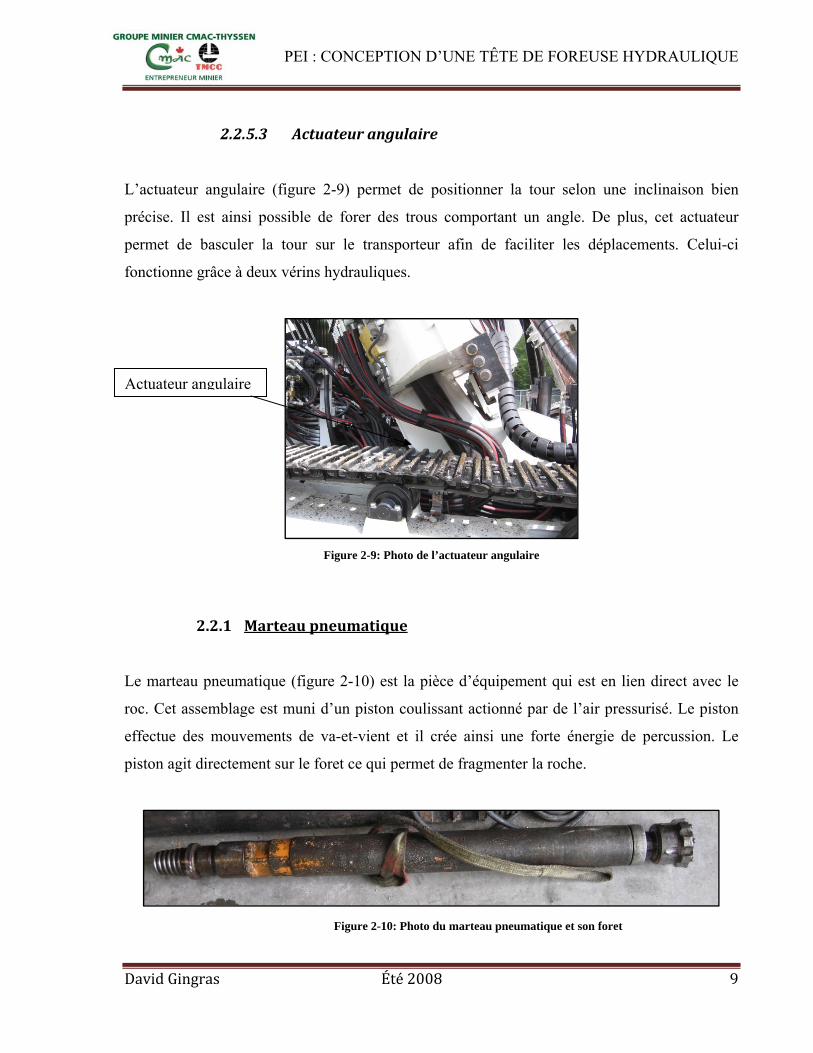
2.2.5.3 Actuateur angulaire
L’actuateur angulaire (figure 2-9) permet de positionner la tour selon une inclinaison bien
précise. Il est ainsi possible de forer des trous comportant un angle. De plus, cet actuateur
permet de basculer la tour sur le transporteur afin de faciliter les déplacements. Celui-ci
fonctionne grâce à deux vérins hydrauliques.
Figure 2-9: Photo de l’actuateur angulaire
2.2.1 Marteau pneumatique
Le marteau pneumatique (figure 2-10) est la pièce d’équipement qui est en lien direct avec le
roc. Cet assemblage est muni d’un piston coulissant actionné par de l’air pressurisé. Le piston
effectue des mouvements de va-et-vient et il crée ainsi une forte énergie de percussion. Le
piston agit directement sur le foret ce qui permet de fragmenter la roche.
Actuateur angulaire
Figure 2-10: Photo du marteau pneumatique et son foret

PEI : CONCEPTION D’UNE TÊTE DE FOREUSE HYDRAULIQUE
David Gingras Été 2008 10
2.2.2 Tiges de forage
Les tiges de forage ont une forme tubulaire pour permettre une circulation d’air, d’eau et
d’huile à l’intérieur. L’air permet d’alimenter le marteau pneumatique et d’évacuer la roche
fragmentée du trou. L’eau atténue la poussière de roche dans l’air et elle contribue à un
rendement supérieur du foret. Une légère quantité d’huile permet la lubrification du marteau.
Les tiges de forage sont munies d’un chemin de clé à chaque extrémité (figure 2-11). Une clé
est insérée dans ces chemins de clé afin de fixer la tige lors de l’ajout ou le retrait d’une tige.
Elles sont munies de filet conique mâle (figure 2-12) à l’extrémité supérieure et de filet femelle
à l’extrémité inférieure. Dans la partie mâle, l’intérieur de la tige est équipé de cannelures;
celles-ci permettent au piston cannelé de s’insérer et d’empêcher le dévissage de la tige (figure
2-13).
Figure 2-11: Tiges de forage avec chemins de clé aux extrémités
Figure 2-12: Cannelures intérieures d'une tige de forage
Figure 2-13: Filet conique mâle d'une tige de forage

PEI : CONCEPTION D’UNE TÊTE DE FOREUSE HYDRAULIQUE
David Gingras Été 2008 11
2.2.3 Unité d’air comprimé
L’air servant à actionner le marteau pneumatique est comprimé par une unité mobile (figure 2-
14) comprenant 3 compresseurs. Cette unité fonctionne à l’énergie électrique et elle est capable
de fournir une pression de 400 PSI d’air.
Figure 2-14: Photo de l'unité mobile d'air comprimé.
2.2.4 Protocole de forage
Dans cette section, nous allons expliquer les différentes opérations pour le forage, l’ajout et le
retrait de tiges de forage.
2.2.4.1 Forage
1. La rotation est activée.
2. Le système d’avance est activé.
2.2.4.2 Ajout d’une nouvelle tige de forage
1. Arrêt de la rotation.

PEI : CONCEPTION D’UNE TÊTE DE FOREUSE HYDRAULIQUE
David Gingras Été 2008 12
2. La clé est engagée dans le chemin de clé supérieur de la tige (Figure 2-15).
3. La rotation est activée dans le sens antihoraire (dévissage du mandrin de la tige)
(Figure 2-15).
4. Actionner le système d’avance vers le haut afin de remonter la tête (Figure 2-16).
5. Ajouter une autre tige de forage (Figure 2-16).
6. Activer doucement la rotation dans le sens horaire pour visser les deux extrémités de la tige
(Figure 2-17).
7. Désengager la clé (Figure 2-17).
2.2.4.3 Dévissage d’une tige de forage
1. Arrêt de la rotation (Figure 2-18).
2. Tirer la tige vers la surface (Figure 2-19).
3. Engager la clé dans le chemin de clé inférieur de la tige (Figure 2-19).
Figure 2-15
Figure 2-16
Figure 2-17
1. Déplacement vers le haut
2. Désengager la clé
1. Visser la tige lentement
2. Ajouter une tige
1. Engager la clé
Niveau du sol
2. Rotation, sens antihoraire

PEI : CONCEPTION D’UNE TÊTE DE FOREUSE HYDRAULIQUE
David Gingras Été 2008 13
4. Actionner la rotation dans le sens antihoraire afin de casser le joint (Ne pas dévisser au
complet) (Figure 2-19).
5. Dégager la clé (Figure 2-19).
6. Tirer la tige suffisamment afin de pouvoir introduire la clé dans le chemin de clé inférieur
immédiat (Dans le chemin de clé supérieur de l’autre tige) (Figure 2-20).
7. Engager la clé (Figure 2-20).
8. Engager le piston cannelé (Figure 2-20).
9. Actionner la rotation dans le sens antihoraire afin de procéder au dévissage complet de la
tige (Figure 2-20).
10. Désengager le piston cannelé » (Figure 2-21).
11. Dévisser la tige de mandrin manuellement (à la mitaine) (Figure 2-21).
12. Descendre la tête afin de visser le mandrin à la tige qui et refaire les étapes de 1 à 11 pour
retirer une autre tige.
Figure 2-18
Figure 2-19
Rotation arrêtée
1. Déplacement vers le haut
2. Engager la clé
3. Casser le joint
4. Désengager la clé
Niveau du sol

PEI : CONCEPTION D’UNE TÊTE DE FOREUSE HYDRAULIQUE
David Gingras Été 2008 14
Figure 2-20
Figure 2-21
2. Engager la clé
1. Léger déplacement vers le haut
4. Casser le joint
3. Engager le piston
1. Désengager le piston
2. Retirer la tige

PEI : CONCEPTION D’UNE TÊTE DE FOREUSE HYDRAULIQUE
David Gingras Été 2008 15
2.3 Revue de la documentation
Nous avons fait des recherches sur des têtes de forage qui existe sur le marché. Nous avons
trouvé deux constructeurs, soit CUBEX et MTI. Nous allons expliquer le fonctionnement des
deux têtes et donner notre opinion face à celles-ci.
2.3.1 CUBEX
L’entreprise manufacturière CUBEX produit des foreuses de type ITH depuis de nombreuses
années. Ils offrent différentes configurations de foreuse. Certaine d’entres elles sont assemblées
sur des transporteurs à chenille et d’autres sur roues. Cette entreprise a mis au point une tête de
foreuse de type ITH. Leur tête utilise le système de dévissage de tiges à piston cannelé. Cette
tête est constituée de deux moteurs hydrauliques de type « gerotor ». Son système de
transmission est assuré par une roue d’engrenage ainsi que deux pignons couplés aux moteurs.
L’admission d’air s’effectue à l’aide d’un assemblage pivotant : « swivel ». La partie inférieure
de cet assemblage est vissée dans le mandrin de la tête. L’autre partie, fixe, permet l’admission
de l’air pour le marteau et pour le piston cannelé. Cette configuration permet à l’opérateur de la
foreuse de remplacer le piston cannelé lorsqu’il est cassé. Il suffit de dévisser et de retirer
l’assemblage pivotant du mandrin. Il est ainsi possible d’extraire la pièce par l’orifice créé.
Beaucoup d’entreprises optent pour les têtes de foreuses CUBEX dû à la rapidité de dévissage
des tiges de forage et de sa fiabilité. Le système de dévissage à piston cannelé est très
performant et permet une configuration de tête beaucoup plus compacte. Le tableau 1 illustre
quelques spécifications de cette tête.
La vue de couple de la figure 2-22 nous montre l'allure du « splined piston breakout system ».
Ce piston cannelé est actionné par une pression d’air contenu dans le cylindre du mandrin. Une
fois actionnées, les cannelures entre dans celles de la tige. Cette action permet d’empêcher tout
mouvement rotatif entre la tige et le mandrin. Une fois l’opération terminée, il suffit de relâcher
la pression d’air dans le cylindre du mandrin. Le ressort appliquera sa force de rappel pour
repositionner le piston dans le haut du cylindre.

PEI : CONCEPTION D’UNE TÊTE DE FOREUSE HYDRAULIQUE
David Gingras Été 2008 16
Tableau 1: Spécifications de la tête CUBEX
Couple maximal : 5730 Nm (4225 ft-Lbs)
Vitesse de rotation maximale : 80 RPM
Pour plus d’information, veuillez-vous référer à l’annexe B.
Assemblage pivotant: «swivel»
Admission d’air (marteau)
Admission d’air (piston cannelé)
Piston cannelé
Moteur hydraulique
Figure 2-22: Vue de coupe de la tête CUBEX
Cylindre
Ressort

PEI : CONCEPTION D’UNE TÊTE DE FOREUSE HYDRAULIQUE
David Gingras Été 2008 17
2.3.2 Mining Technologies International Inc.
L’entreprise MTI produit aussi des foreuses de type ITH depuis de nombreuses années. C’est
principalement des foreuses de marque MTI que Forage Long-trou CMAC-THYSSEN possède.
MTI utilise un système bien différent de CUBEX. Leur tête de foreuse est composée de deux
assemblages. Le premier assemblage (figure 2-23) est la partie motrice de la tête. Sa motricité
est assuré par deux moteurs hydrauliques de type « gerotor ». Selon l’emplacement des
moteurs, l’équilibre des charges radiales sur les roulements de l’axe central est impossible. Le
deuxième assemblage (figure 2-24) est inséré dans la partie motrice et il comporte le système de
dévissage des tiges. Ce système est composé d’une clé actionnée par deux cylindres
hydraulique. C’est le deuxième assemblage qui assure le lien entre la partie motrice et les tiges,
c’est-dire- qu’il tourne avec les tiges.
Figure 2-23: Partie motrice de la tête MTI

PEI : CONCEPTION D’UNE TÊTE DE FOREUSE HYDRAULIQUE
David Gingras Été 2008 18
Figure 2-24: Système de dévissage de la tête MTI
La tête MTI est deux fois plus imposante que celle fabriqué par CUBEX et elle possède un
poids énorme. De plus, des foreurs travaillant avec cette la tête MTI nous ont informé qu’il est
beaucoup plus long de retirer une colonne de tiges de forage avec ce système de dévissage. Par
ailleurs, notre représentant industriel nous a informé qu’il est plus difficile de faire l’entretien
de cette tête. Nous n’avons trouvé aucun avantage signification d’utiliser ce concept. Forage
Long-trou remplace ces têtes par celles fabriquées par CUBEX. Alors, il est évident que nous
n’opterons pas pour une conception similaire à la tête MTI. Nous allons plutôt opter pour un
design ressemblant à celui de la tête CUBEX.

PEI : CONCEPTION D’UNE TÊTE DE FOREUSE HYDRAULIQUE
David Gingras Été 2008 19
2.4 Objectifs, contraintes et restrictions
2.4.1 Objectifs
• L’entreprise demande l’utilisation du système intitulé « Splined Piston breakout
system », soit le système de dévissage à piston cannelé;
• La tête doit être conçue afin d’être le plus compact possible;
• La tête doit être la plus légère possible;
• Définir le nombre de moteur(s) requis.
2.4.2 Contraintes
• La tête de forage doit offrir un couple de 5730 Nm;
• La vitesse de rotation maximale est de 80 RPM;
• La tête devra supporter une compression et une traction de 70 kN;
• La tête devra alimenter le marteau avec une pression d’air de 2,413 Mpa;
• Arriver à un coup de fabrication inférieur à 38 000$;
• Concevoir la tête afin que l’entreprise puisse la fabriquer dans ses installations;
• Fixation de la tête au chariot par les côtés.
2.4.3 Restrictions
• La source de puissance pour la rotation est de type hydraulique;
• L’utilisation d’acier pour la fabrication est requise; • L’utilisation d’aluminium est non permise.

PEI : CONCEPTION D’UNE TÊTE DE FOREUSE HYDRAULIQUE
David Gingras Été 2008 20
2.5 Formulation du mandat
Au cours du présent projet, notre principal mandat est de conceptualiser une tête rotative de
foreuse de type ITH. Manufacturier CMAC-THYSSEN souhaite, dans la mesure du possible,
fabriquer celle-ci avec ces installations déjà existantes, ce qui est pris en considération. Pour
répondre aux exigences de la compagnie, nous devons parallèlement fournir tous les dessins de
détails, vérifier, à l’aide des calculs, la résistance des composantes ainsi que de concevoir un
système de dévissage des tiges de forage en utilisant celui à piston cannelé: « splined piston
breakout system ». De plus, il faut concevoir cette tête afin qu’elle soit la plus compacte et la
plus légère possible. Le nombre de moteurs requis pour fabriquer et utiliser la tête de foreuse
doit aussi être spécifié. Finalement, une attention particulière sera portée sur les contraintes et
les restrictions citées à la précédente section.

PEI : CONCEPTION D’UNE TÊTE DE FOREUSE HYDRAULIQUE
David Gingras Été 2008 21
3. ANALYSE DES DESIGNS
Dans cette section, on trouve une analyse sur différents sujets permettant de répondre aux
objectifs du projet. Le design de la tête sera grandement inspiré de la tête de CUBEX étant
donné qu’elle est très bien conçue. Forage Long-trou CMAC-THYSSEN remplace les têtes
MTI sur ses foreuses par des têtes CUBEX. Selon eux, elles permettent une production de
forage largement supérieure. Notre conception sera élaborée à partir d’un mandrin équipé d’un
système de dévissage à piston cannelé : « splined piston breakout system ». Une analyse, quant
au nombre de moteurs, sera réalisé afin de procéder au design de la transmission. Des études
seront faites sur celle-ci afin de déterminer le ratio qui permettra d’obtenir des couples et des
vitesses moteurs raisonnables. Une transmission par chaîne et par engrenage sera aussi
analysée.
3.1 Nombre de moteurs
Nous allons comparer différents scénarios quant au nombre de moteurs requis. Il sera ainsi plus
facile de déterminer le nombre de moteurs. Nous serons donc en mesure de concevoir la
transmission et ces composantes.
3.1.1 Un moteur
L’utilisation d’un seul moteur permet de réduire le risque de défaillance de la tête. Le risque de
défaillance est directement lié au nombre de composantes d’un assemblage. Cependant, étant
donné la puissance requise au bon fonctionnement de la tête, le moteur doit être capable de
fournir le couple à la vitesse de rotation requise. Pour ce faire, nous devons sélectionner un
moteur ayant une grande cylindrée. Selon une recherche effectuée auprès de distributeurs de
moteurs hydrauliques, le coût de ces moteurs est très élevé. L’équilibre des charges radiales
appliquées sur les roulements du mandrin ne peut être possible avec l’utilisation d’un seul
moteur.

PEI : CONCEPTION D’UNE TÊTE DE FOREUSE HYDRAULIQUE
David Gingras Été 2008 22
3.1.2 Deux moteurs
Une combinaison de deux moteurs permet d’équilibrer les charges radiales appliquées sur les
roulements du mandrin. La cylindrée des moteurs peut être révisée à la baisse étant donné que
le couple requis sera fourni par deux moteurs. Il est donc possible de sélectionner des moteurs
qui sont d’usage courant dans l’industrie. Ce sera plus économique d’acheter deux petits
moteurs plutôt qu’un gros. Le risque de défaillance, dû aux moteurs de la tête de forage, est
légèrement augmenté, mais non significatif. De plus, la disposition de deux moteurs ne
compromet pas la complexité de design de la tête de forage.
3.1.3 Plus de deux moteurs
Il est possible de disposer plusieurs moteurs afin d’équilibrer les charges radiales au mandrin.
Par contre, l’utilisation de plus de deux moteurs augmente la complexité du design; le
positionnement des moteurs est plus difficile; le nombre de pièces est augmenté dû à l’ajout de
roulements et de pignons supplémentaires; et également son risque de défaillances. De plus, il
faut prévoir des conduites hydrauliques supplémentaires.
Selon les pours et les contres, nous croyons que l’utilisation de deux moteurs est le plus
avantageux afin d’avoir une tête de foreuse fiable et produite à un faible coût.
3.2 Transmission de puissance
Les paramètres de design du tableau 2 ont été fixés selon les spécifications désirées de la tête
hydraulique. Nous avons utilisé ceux de la tête CUBEX. Lors du forage, le couple est inférieur
et la vitesse de rotation également. L’analyse de la transmission est faite en considérant que la
tête sera sollicitée avec des conditions extrêmes. Ceci permet d’avoir une meilleure certitude
quant à la robustesse de la tête. Nous utiliserons deux moteurs pour mener notre étude.

PEI : CONCEPTION D’UNE TÊTE DE FOREUSE HYDRAULIQUE
David Gingras Été 2008 23
Tableau 2: Paramètres de design
Vitesse de rotation maximale du mandrin 80 [RPM]
8,38 [rad/sec]
Couple maximal au mandrin 4225 [Lbs-ft]
5730 [Nm]
Afin d’analyser un scénario de design de transmission, nous utiliserons les dimensions des
pignons et de la roue de tableau 3.
Tableau 3: Dimension des pignons et de la roue
Diamètre
[pouce]
Pignon 4,25
Roue 11
Toutes les équations dans la présente section ont été tirées du livre Éléments de machines
chapitres 11 et 15.
3.2.1 Vitesse de rotation des pignons
Nous calculons la vitesse de rotation des pignons afin de connaître la vitesse de rotation des
moteurs hydrauliques.
3.1
11 4,25 80 207,06

PEI : CONCEPTION D’UNE TÊTE DE FOREUSE HYDRAULIQUE
David Gingras Été 2008 24
[RPM]
è
è
Nous obtenons une vitesse de rotation des moteurs de 207,06 RPM pour une vitesse de rotation
du mandrin de 80 RPM.
3.2.1 Puissance transmise au mandrin
Nous calculons la puissance au mandrin pour connaître la sollicitation dynamique du mandrin.
Cette puissance sera utilisée afin de vérifier la résistance du mandrin. De plus, nous sommes
intéressé de connaître la puissance que les moteurs hydrauliques devront développer.
3.2
5730 80 9,5493 48,000
où
/
Étant donné que la puissance fournie au mandrin provient de deux moteurs, nous allons diviser
la puissance calculée ci-dessus par deux. Alors, la puissance fournie par un moteur est de
24 kW. Les pertes énergétiques ont été négligées afin d’alléger l’analyse.

PEI : CONCEPTION D’UNE TÊTE DE FOREUSE HYDRAULIQUE
David Gingras Été 2008 25
3.2.2 Couple appliqué aux pignons
Le calcul du couple aux pignons permettra de calculer la charge tangentielle appliquée sur une
dent ainsi que de connaître le couple que les moteurs devront développer.
3.3
24,00kW 9,5493 RPM207,6 RPM rad/sec 1104 Nm
où
é
Le couple aux pignons est de 1104,00 Nm. Nous avons donc besoin de deux moteurs
développant 1104 Nm chacun.
Les dimensions primitives des engrenages ont été sélectionnées après une étude développée sur
Excel sur différents scénarios de ratio et de résistance des engrenages. Nous trouvons une
image de la feuille Excel de cette étude dans l’annexe C. Le tableau 4 résume cette étude. Le
ratio choisi a été sélectionné en fonction de la largeur totale de la transmission, du couple requis
au moteur et la vitesse de rotation des moteurs. Le diamètre des engrenages et le ratio choisi est
en caractère gras dans le tableau 4.

PEI : CONCEPTION D’UNE TÊTE DE FOREUSE HYDRAULIQUE
David Gingras Été 2008 26
Tableau 4: Ratios, vitesses et couples moteur
Diamètre [pouce]
Roue Pignon Ratio
Couple
moteur
[Nm]
Vitesse
moteur
[RPM]
Puissance
moteur [kW]
12,00 12,00 1,00 2865,00 80,00 24,00
12,00 11,00 0,92 2626,25 87,27 24,00
12,00 10,00 0,83 2387,50 96,00 24,00
12,00 9,00 0,75 2148,75 106,67 24,00
12,00 8,00 0,67 1910,00 120,00 24,00
12,00 7,00 0,58 1671,25 137,14 24,00
12,00 6,00 0,50 1432,50 160,00 24,00
12,00 5,00 0,42 1193,75 192,00 24,00
12,00 4,00 0,33 955,00 240,00 24,00
12,00 3,00 0,25 716,25 320,00 24,00
11,00 11,00 1,00 2865,00 80,00 24,00
11,00 10,00 0,91 2604,55 88,00 24,00
11,00 9,00 0,82 2344,09 97,78 24,00
11,00 8,00 0,73 2083,64 110,00 24,00
11,00 7,00 0,64 1823,18 125,71 24,00
11,00 6,00 0,55 1562,73 146,67 24,00
11,00 5,00 0,45 1302,27 176,00 24,00
11,00 4,25 0,39 1106,93 207,06 24,00
11,00 3,00 0,27 781,36 293,33 24,00
Le calcul des couples moteurs ont été fait en considérant que la tête est composée de deux
moteurs hydrauliques. Dans le tableau 4, il est observable que certain ratio demande des
couples moteurs énormes. Nous avons choisi le ratio (en caractère gras, tableau 4) de 0,39. Ce
choix nous permet de sélectionner des moteurs hydrauliques standard et facilement disponible
sur le marché.

PEI : CONCEPTION D’UNE TÊTE DE FOREUSE HYDRAULIQUE
David Gingras Été 2008 27
3.2.3 Largeur de la transmission
La largeur de la transmission est un facteur très important puisque l’un de nos objectifs est la
conception d’une tête de format compact. La notion de largeur de transmission définit plus
précisément la dimension de la transmission sur le sens de ça longueur. La dimension de la
transmission est dépendante du nombre et de la dimension des poulies ou des engrenages
composant la transmission. La largeur de la transmission par chaîne est fonction du diamètre
des poulies et de l’entraxe minimal afin d’obtenir l’angle d’enroulement minimal requis sur le
ou les pignons. Quant à-elle, la taille de la transmission par engrenages est fonction des
diamètres des engrenages. Les figures 3-1 et 3-2 nous schématisent la notion de largeur des
deux types de transmission en considérant l’utilisation de deux moteurs, soit deux pignons et
une roue. Nous allons calculer la largeur d’une transmission par engrenage et par chaîne selon
les diamètres du pignon et de la roue de tableau 3.
Figure 3-1: Largeur de la transmission par
engrenages
Figure 3-2: Largeur de la transmission par chaînes
3.2.1 Largeur de la transmission à engrenages
Nous calculons la largeur d’une transmission à engrenages.
2 3.4
2 4,25 11 19,5
où
Une transmission par engrenages engendre une largeur de 19,5 pouces.
Largeur de la transmission Largeur de la transmission

PEI : CONCEPTION D’UNE TÊTE DE FOREUSE HYDRAULIQUE
David Gingras Été 2008 28
3.2.1.1 Largeur d’une transmission à chaîne
Pour qu’une transmission par chaîne fonctionne correctement, la chaîne doit respecter un angle
d’enroulement de plus de 120° sur le pignon. Alors, dans le calcul ci-dessous, nous allons
vérifier l’entraxe (C) (figure 3-3) minimal. L’équation 3.5 est tirée du livre Éléments de
machines.
Figure 3-3: Image d'un entraxe de chaîne
2sin 120° 180°2
3.5
4,25 11
2sin 120° 180°2
6,75
où
Nous avons calculé un entraxe minimal de 6,75 pouces, cependant il est impossible de prévoir
cet entraxe selon le diamètre de la roue et des pignons. Dans ce cas, la distance minimale doit
être la somme du rayon de la roue et du pignon. Voici une relation qui permet de calculer cette
distance.
2 2 3.6
4,252
112 7,625

PEI : CONCEPTION D’UNE TÊTE DE FOREUSE HYDRAULIQUE
David Gingras Été 2008 29
où
Selon le diamètre de la roue et des pignons, il est nécessaire de respecter une distance minimale
de 7,625 pouces afin de créer un assemblage réaliste, sans interférence. Nous prévoyons une
distance de 0,5 pouce entre les poulies pour s’assurer qu’il n’y ait aucun contact entre la roue et
le pignon.
î 2 0,5 3.7
î 2 7,625 0,5 4,25 20,5
où
î î
Alors, pour respecter la condition d’enroulement de la chaîne sur les pignons, nous obtenons un
entraxe de 6,75 pouces. Avec l’utilisation de deux moteurs, nous obtenons une largeur totale de
la transmission de 20,5 pouces. Tableau 5: Largeur de la transmission, chaîne versus engrenages
Diamètre
[pouce]
Largeur transmission
[pouce]
Diamètre
[pouce]
Largeur transmission
[pouce]
Roues Pignons Chaîne Engrenages Roues Pignons Chaîne Engrenages12,00 12,00 37,00 36,00 11,00 11,00 34,00 33,00
12,00 11,00 35,00 34,00 11,00 10,00 32,00 31,00
12,00 10,00 33,00 32,00 11,00 9,00 30,00 29,00
12,00 9,00 31,00 30,00 11,00 8,00 28,00 27,00
12,00 8,00 29,00 28,00 11,00 7,00 26,00 25,00
12,00 7,00 27,00 26,00 11,00 6,00 24,00 23,00
12,00 6,00 25,00 24,00 11,00 5,00 22,00 21,00
12,00 5,00 23,00 22,00 11,00 4,25 20,50 19,50
12,00 4,00 21,00 20,00 11,00 3,00 20,00 17,00
12,00 3,00 22,00 18,00

PEI : CONCEPTION D’UNE TÊTE DE FOREUSE HYDRAULIQUE
David Gingras Été 2008 30
Selon l’objectif d’un format compact, une transmission par engrenages semble la solution. Le
tableau 5 montre la largeur de la transmission selon plusieurs dimensions de pignons et de
roues.
3.3 Analyse d’une transmission par engrenages
Nous allons maintenant vérifier la possibilité d’une transmission à engrenages. Pour ce faire,
nous allons vérifier le facteur de service des engrenages selon les dimensions d’engrenages du
tableau 6 et le type d’acier utilisé (IC 4340). Nous allons également vérifier le risque d’usure
des engrenages ainsi que l’interférence.
Figure 3-4: Image de la transmission par engrenages
Les dimensions d’engrenages du tableau 6 seront utiliser afin d’analyser un scénario pour la
transmission par engrenages. Par ailleurs, ses dimensions d’engrenages permettent d’obtenir
des couples et des vitesses moteurs raisonnables. C’est-à-dire qui est facile de trouver des
moteurs hydrauliques ayant les performances requises pour un tel ratio. Nous allons vérifier si
le pas diamétral et suffisant afin d’obtenir des dents d’engrenages résistante aux forces
appliquées lors du forage.
MandrinPignon
Roue

PEI : CONCEPTION D’UNE TÊTE DE FOREUSE HYDRAULIQUE
David Gingras Été 2008 31
Tableau 6: Dimensions primitives des engrenages
Engrenages
Diamètre
primitif [pouce]
Largeur
[pouce]
Pas
diamétral
Angle de
pression
Roue 11 3,5 4 20°
Pignon 4,25 3,5 4 20°
3.3.1 Charge tangentielle appliquée sur une dent
Nous allons calculer la charge tangentielle appliquée sur une dent. Cette charge sera utilisée
pour calculer sa résistance.
2 3.8
57302 0,2794 20508,23 4610,43
où
é
Nous obtenons une charge tangentielle de 20,51 [kN]
3.3.2 Nombre de dents pour chacun des engrenages
Le nombre de dents est un paramètre indispensable pour calculer la résistance des engrenages.
3.9
où
é
è

PEI : CONCEPTION D’UNE TÊTE DE FOREUSE HYDRAULIQUE
David Gingras Été 2008 32
Tableau 7: Nombre de dents des engrenages
Engrenage Nombre de dents
Roue 44
Pignon 17
L’imparité du nombre de dents du pignon a été fixée volontairement. Un nombre impair de
dents sur l’un des engrenages permet de s’assurer l’usure uniforme des dents des engrenages.
3.3.3 Résistance des engrenages
Il est important de vérifier si les engrenages seront en mesure de supporter les charges selon
leur dimension. Nous allons procéder à des calculs afin de déterminer le facteur de service de
chaque engrenage.
3.3.3.1 Contrainte en flexion sur la dent
Afin de considérer les concentrations de contraintes dues au rapport de conduite et des effets
dynamiques, nous utilisons l’équation de Lewis modifié (AGMA). Cette relation nous
permettra de prédire les contraintes relatives en flexion que les dents devront supporter lors du
fonctionnement de la tête. Nous devons utiliser le système anglais pour travailler cette équation.
3.10
où
[Pouce]
é é

PEI : CONCEPTION D’UNE TÊTE DE FOREUSE HYDRAULIQUE
David Gingras Été 2008 33
é
Tableau 8: Facteurs de contraintes et contraintes relatives en flexion
Wt
[Lbf]
F
[pouce]
P Kv J KO Km Ks σ
[PSI] Engrenage
Roue 4610,43 3,5 4 0,767 0,40 1,25 1,6 1 34 342,92
Pignon 4610,43 3,5 4 0,767 0,30 1,25 1,6 1 45 790,58
Le tableau 8 résume les paramètres utilisés pour le calcul des contraintes en flexion des
engrenages. Selon les dimensions d’engrenages du tableau 6, nous obtenons une contrainte en
flexion des dents d’engrenages de 34 343 PSI pour les pignons et de 45 791 PSI pour la roue.
Calcul du Kv
5050 √
3.11
5050 √230,38
0,767
1280 tr π 11pouce pied
tr min 12 pouce 230,38 pied/min 3.12
La valeur du facteur J a été trouvée en fonction d’un graphique (Annexe D, page 106). Le
facteur KO a été obtenu en supposant une source de puissance uniforme (moteur hydraulique) et
machine entraînée offrant des chocs moyens (contre réaction des tiges de forages). Le facteur
Km à été obtenu en supposant un montage et des engrenages de précision moyenne. Ces
informations ont été obtenues dans le livre Éléments de machines chapitre 11. Il est possible de
trouver plus d’information sur ces facteurs de résistance à l’annexe D.

PEI : CONCEPTION D’UNE TÊTE DE FOREUSE HYDRAULIQUE
David Gingras Été 2008 34
3.3.3.2 Résistance en flexion de l’acier
Maintenant que nous avons calculé les contraintes en flexion, nous allons calculer la résistance
en flexion de la dent. Ce calcul tient compte de différents facteurs d’utilisation et de la limite
ultime en rupture du matériau choisi, soit l’acier IC 4340.
3.13
où
é
é
é
0,5
à
Tableau 9: Facteur de flexion et résistance de l'acier
Engrenages
Sut [PSI] [PSI] ka kb kc kd ke Se
[PSI]
Roue 200 000 100 000 0,65 0,85 1 1 1 55 250
Pignon 200 000 100 000 0,65 0,85 1 1 1 55 250
Acier utilisé = IC 4340
La variable Se (tableau 9) nous indique la résistance en flexion de l’acier 4340, soit 55 250 PSI.
Les facteurs de résistance en flexion de l’acier ont été fixés selon différents paramètres tels que;
le fini de surface, la grosseur des dents, la fiabilité du système, la limite de rupture de l’acier
utilisée, la température de fonctionnement, la concentration de contrainte et les effets divers.
Ces informations ont été obtenues dans le livre Éléments de machines. Pour plus d’information,
consulter l’annexe D.

PEI : CONCEPTION D’UNE TÊTE DE FOREUSE HYDRAULIQUE
David Gingras Été 2008 35
3.3.4 Facteur de service
Le facteur de service en flexion nous donne une appréciation quant à la robustesse des
engrenages.
,55 250
34 342,92 1,61 3.14
Tableau 10: Facteurs de service en flexion des engrenages
Engrenages FSflex
Roue 1,61
Pignon 1,21
Selon le tableau 10, la roue et les pignons pourront respectivement supporter 61 % et 21 % plus
de charges que celles du design. Ceci est un faible facteur de service, cependant il faut tenir
compte que la tête de forage ne sera pratiquement jamais soumise à de telles charges. De plus,
généralement, la vitesse de rotation lors du forage est d’environ 40 RPM.
Le tableau 11 affiche tous les facteurs de services en flexion des engrenages selon différentes
configurations. Tableau 11: Facteurs de service de la résistance en flexion
Diamètre [pouce] Facteurs de services Diamètre [pouce] Facteurs de services
Roues Pignons Roues Pignons Roues Pignons Roues Pignons 12,00 12,00 1,74 1,74 11,00 11,00 1,61 1,61
12,00 11,00 1,74 1,74 11,00 10,00 1,61 1,61
12,00 10,00 1,74 1,74 11,00 9,00 1,61 1,61
12,00 9,00 1,74 1,74 11,00 8,00 1,61 1,61
12,00 8,00 1,74 1,74 11,00 7,00 1,61 1,61
12,00 7,00 1,74 1,74 11,00 6,00 1,61 1,61
12,00 6,00 1,74 1,74 11,00 5,00 1,66 1,41
12,00 5,00 1,85 1,52 11,00 4,25 1,61 1,21
12,00 4,00 1,79 1,41 11,00 3,00 1,61 1,61
12,00 3,00 1,74 1,74 11,00 11,00 1,61 1,61

PEI : CONCEPTION D’UNE TÊTE DE FOREUSE HYDRAULIQUE
David Gingras Été 2008 36
3.3.5 Résistance à l’usure
L’engagement de deux engrenages génère un frottement entre les dents. Pour s’assurer que le
frottement ne créera pas d’usure prématurée, il suffit de calculer ce facteur pour chaque
engrenage. Le facteur de services d’usure sera calculé à l’aide des dimensions d’engrenage du
tableau 6 et de la dureté Brinell de l’acier.
3.3.5.1.1 Contraintes de surface
Cette équation nous permet de connaître la contrainte de surface des dents des engrenages.
Cette contrainte est à la pression générée par le contact de deux dents. La dureté Brinell de
l’acier IC 4340 est de 450. Le calcul se fait dans le système anglais.
, 3.15
, 23004610,43 1,25 1,6 10,77 3,5 4,25 ,12 188 386,2
où
,
é
Tableau 12: Contraintes de surfaces
Engrenages σH [PSI]
Roue 117 097,39
Pignon 188 386,2

PEI : CONCEPTION D’UNE TÊTE DE FOREUSE HYDRAULIQUE
David Gingras Été 2008 37
En suivant les mêmes étapes de calcul, nous avons obtenu une contrainte de surface de
117 097,39 PSI pour la roue. La relation 3.15 provient du livre Éléments de machines chapitre
11.
3.3.5.1.2 Résistance en fatigue relative aux contraintes de surface
Cette résistance nous informe sur la fatigue relative aux contraintes de surface. Ce calcul a été
fait selon les recommandations de l’AGMA.
400 10 000 3.16
400 450 10 000 170 000
3.17
1 11 0,8 170 000 318 750
où
é
é
é é
é
é
é
é
Nous avons utilisé un facteur de durée de 0,8 caractérisant une durée de vie infinie. Le rapport
de dureté est de 1,0 lorsqu’il s’agit d’engrenages cylindriques droits comme c’est le cas. Le
facteur de température est de 1,0 puisque nous estimons que la température interne de la
transmission est inférieure à 250°F. Le facteur de fiabilité a été fixé à 0,8 représentant une
fiabilité inférieure à 99 %.

PEI : CONCEPTION D’UNE TÊTE DE FOREUSE HYDRAULIQUE
David Gingras Été 2008 38
3.3.5.1.3 Facteur de service d’usure
Un facteur d’usure supérieur à 1,0 n’indique pas un risque d’usure prématuré dû aux contraintes
de surface.
,,
3.18
,318 750 188 386,2 1,69
Tableau 13: Facteur de service selon l'usure
Engrenages FSusure
Roue 2,72
Pignon 1,69
Nous obtenons un facteur d’usure de 2,72 pour la roue et de 1,69 pour les pignons (tableau 13).
Par ces facteurs de service, nous pouvons écarter les risques d’usure précoce des engrenages.
3.3.6 Dimensionnement des engrenages
Jusqu’à maintenant nous avons élaboré nos calculs avec le diamètre primitif des engrenages. En
réalité, le diamètre hors tout est supérieur à celui-ci. Selon la standardisation (AGMA) des
engrenages, il est possible de calculer les dimensions spécifiques des engrenages en considérant
le diamètre primitif et le pas diamétral. Ces dimensions serviront par la suite à calculer s’il y a
risque d’interférence.
3.3.6.1 Exemple de calcul des rayons de saillie et de base
Les équations suivantes ont été prises dans le livre Éléments de machines chapitre 11.

PEI : CONCEPTION D’UNE TÊTE DE FOREUSE HYDRAULIQUE
David Gingras Été 2008 39
,1
3.19
,14 5,5 5,75
,1,25
3.20
, 5,5 1,254 5,1875
Le tableau 14 montre les données standardisé par l’AGMA pour le calcul des dimensions des
engrenages. Tableau 14: Données pour les dimensions des engrenages
Variable P < 20
Pas diamétral 4
Angle de pression 20°
Saillie 1/P
Creux 1,25/P Tiré de AGMA Information Sheet-Strength of Spur, Helical, Herringbone and Bavel Teeth (AGMA 225.01), avec la permission de
l’éditeur, the American Gear Manufacturers Association, 1330 Massachusette Avenue, N.W., Washington, DC 20005.
Tableau 15: Dimension des engrenages sélectionnés
où
è
°
Engrenages D [pouce] R [pouce] RO,i [Pouce] Rb,i [Pouce] °
Roue 11 5,5 5,75 5,1875 20°
Pignon 4,25 2,125 2,375 1,8125 20°

PEI : CONCEPTION D’UNE TÊTE DE FOREUSE HYDRAULIQUE
David Gingras Été 2008 40
é /
Une représentation schématique, tiré du livre Éléments de machines, des différents rayons ce
trouve à l’annexe D à la page 109.
3.3.7 Calcul de l’interférence
Il est très important de vérifier si le dimensionnement des engrenages permettra de
conceptualiser une transmission fonctionnelle. Pour ce faire, il suffit de calculer l’interférence
de l’engagement des engrenages. Cette interférence sera calculée selon la théorie de livre
Éléments de machines chapitre 11.
sin 3.21
2,125 sin 20° 0,727
, , 3.22
5,75 5,1875 2,48
sin 3.23
5,5 sin 20° 1,88
3.24
2,48 1,88 0,6
où
é (voir annexe D page 109 pour une représentation des différents points)

PEI : CONCEPTION D’UNE TÊTE DE FOREUSE HYDRAULIQUE
David Gingras Été 2008 41
Alors pour s’assurer qu’il n’y a pas d’interférence, il faut respecter cette condition;
0 3.25
0,727 0,6 0,127 0 3.26
La différence est supérieure à zéro, donc il est concevable de réaliser une transmission à
engrenage avec de telles dimensions.
3.4 Analyse du pignon et de son arbre
Selon l’application des forces, il est observable que le roulement est sollicité seulement
avec une charge radiale. Il n’y a donc pas de charge axiale. Nous allons donc calculer les
réactions sur le pignon et son arbre afin de connaître les charges que les roulements devront
supporter (figure 3-5).
20°
Force appliqué 20,508 KN
RCz
RDy
RDz
RCy
Figure 3-5: Image des réactions sur le pignon et son arbre

PEI : CONCEPTION D’UNE TÊTE DE FOREUSE HYDRAULIQUE
David Gingras Été 2008 42
3.4.1 Calculs des réactions
3.4.1.1 Somme des moments (∑
∑ 0 0,1397 20,508 20° 0,06985 0 3.27
9,636
La réaction en RDz est la même puisque la pièce est symétrique.
3.4.1.2 Somme des moments (∑
∑ 0 0,1397 20,508 20° 0,06985 0 3.28
3,507
La réaction en RDy est la même puisque la pièce est symétrique.
3.4.1.3 Charge radiale statique résultante
, 3.29
, 9,636 3,507 10,254
é
é
é

PEI : CONCEPTION D’UNE TÊTE DE FOREUSE HYDRAULIQUE
David Gingras Été 2008 43
é
Alors, les roulements des pignons devront supporter une charge radiale de 10,254 kN.
3.5 Analyse dynamique du mandrin
Nous allons vérifier la résistance du mandrin selon l’énergie de déformation en torsion.
3.5.1 Énergie de déformation en torsion
Nous utilisons la théorie développée dans le chapitre 14 de livre de Résistance des matériaux,
page 411, pour calculer l’énergie de déformation en torsion du mandrin. De plus, nous utilisons
les paramètres du tableau 16. Tableau 16: Paramètres de calculs pour le mandrin
t L r G
0,0159 [m] 0,1143 [m] 0,0746 [m] 689 MPa
Figure 3-6: Image du mandrin
2 3.30
5730 0,11432 689 10 4,15 10 65,655
2 3.31
L
r
t

PEI : CONCEPTION D’UNE TÊTE DE FOREUSE HYDRAULIQUE
David Gingras Été 2008 44
2 0,0746 0,0159 4,15 10
É é
é é
É
La puissance maximale à laquelle le mandrin sera soumis lors de la rotation est de 48 kW.
L’énergie requise afin que le mandrin se déforme est de 65,66 kW. Nous avons donc la
conviction que le mandrin sera en mesure de supporter le couple maximal. Cependant, ce calcul
ne tient pas compte de l’énergie de poussé et de vibrations.
3.6 Analyse des roulements
Dans cette section, nous allons vérifier la durée de vie des roulements selon les charges
auxquelles ils seront sollicités. Nous n’avons pas considéré de facteurs de charge puisque nous
élaborerons ces calculs selon les paramètres de design du tableau 17 La tête ne sera
pratiquement jamais sollicitée avec de telles charges. Tous ces calculs ont été faits selon la
méthode du fabriquant. Nous trouvons cette méthode et plus d’informations sur les roulements
à l’annexe G. Tableau 17 : Paramètres de design des roulements
Charge radiale [kN] Charge axiale [kN] Vitesse [RPM]
Roulements des pignons 10,254 0 103,53
Roulements du mandrin 0 35,141 40
Nous avons divisé les vitesses de rotation par deux puisque c’est à 40 RPM que les foreuses
sont ajustées. De plus, nous avons réduit de 25% la charge axiale puisqu’il est pratiquement

PEI : CONCEPTION D’UNE TÊTE DE FOREUSE HYDRAULIQUE
David Gingras Été 2008 45
impossible d’appliquer cette charge axiale tout en ayant une rotation de 40 RPM. Ces divisions
nous permettrons d’obtenir des durées de vie plus près de la réalité.
3.6.1 Roulements des pignons
Cette équation permet de calculer la charge dynamique équivalente des roulements des pignons.
, , , 1 10,254 0 0 10,254 3.32
, é
,
,
0,6871,5 10,254 4,74 3.33
é
Alors, selon les spécifications du roulement à gorge profonde (6311) fabriqué par NTN, nous
obtenons une durée de vie de 55 000 heures. Si nous considérons un temps de fonctionnent de
16 heures par jour pendant 365 jours par année, nous obtenons une durée de vie de 9,4 ans.
Cette durée de vie a été calculée en fonction du couple maximal. Donc, puisque la foreuse
n’applique pas son couple maximal continuellement, le roulement aura une durée minimale de
9,4 ans.

PEI : CONCEPTION D’UNE TÊTE DE FOREUSE HYDRAULIQUE
David Gingras Été 2008 46
3.6.2 Roulements du mandrin
Cette équation permet de calculer la charge dynamique équivalente des roulements du mandrin.
, , , 1 0 1,57 35,14 55,17 3.34
, é
,
,
0,95254 55,17 4,37 3.35
é
Selon les spécifications du roulement conique (4T-46790/46720) fabriqué par NTN, nous
obtenons une durée de vie de 60 000 heures. Si nous considérons un temps de fonctionnement
de 16 heures par jour pendant 365 jours par année, nous obtenons une durée de vie de 10,27
ans.
Ceci conclu les études et les analyses que nous avons fait. Cependant, il y a des études et des
analyses complémentaires à faire avant d’exécuter la conception de cette tête.

PEI : CONCEPTION D’UNE TÊTE DE FOREUSE HYDRAULIQUE
David Gingras Été 2008 47
4. DESCRIPTION DU DESIGN
Maintenant que nous avons vérifié la faisabilité de différents scénarios, nous allons décrire le
design final quant à la conception de cette tête de foreuse hydraulique. Nous allons aussi
expliquer les raisons du choix de ce design et des composantes. Les figures 4-1 et 4-2 sont des
images de la tête modélisée à l’aide du logiciel Inventor.
Figure 4-1: Image de la vue supérieure de la tête
Figure 4-2: Image de la vue inférieure de la tête
4.1 Puissance hydraulique
La puissance hydraulique sera fournie par deux moteurs hydrauliques de type Gerotor. Nous
avons sélectionné un moteur fabriqué par PARKER, catalogue HY30-3213/DE/UK/FR/IT. Ce
type de moteur a la propriété d’offrir des couples à faible révolution par minute, voir courbe de
fonctionnement (figure 4-3). Pour notre application, ce moteur est idéal. Pour être plus précis,
nous avons opté pour la série TG et le modèle 335 (figure 4-4). Ce moteur offre un couple
maximal de 1350 Nm et une vitesse de rotation maximale de 290 RPM. Ils offrent un couple
légèrement supérieur à celui requis, ils seront donc en mesure de couvrir les pertes mécaniques.
Cependant, le système hydraulique devra être ajusté afin que les moteurs ne produisent pas un
couple supérieur à la capacité de la transmission. Suite à des vérifications avec un distributeur
PARKER (Hydraulique Val-d’Or), nous avons été informés que ce moteur est d’usage très
courant dans différents secteurs de l’industrie. Hydraulique Val-d’Or possède généralement une

PEI : CONCEPTION D’UNE TÊTE DE FOREUSE HYDRAULIQUE
David Gingras Été 2008 48
demi-douzaine d’exemplaires de ces moteurs dans son inventaire. Alors, les délais de livraison
seront de moins d’une journée, le rendant encore plus intéressant pour l’entreprise.
Figure 4-3: Courbe du fonctionnement du moteur TG-335
Figure 4-4: Photo du TG-335
4.2 Transmission, engrenages versus chaîne
Nous avions vérifié la possibilité de deux systèmes de transmission, soit par chaîne et par
engrenages. Une transmission par chaîne nécessite une précision de montage inférieure à une
transmission par engrenages et, son entretien est beaucoup plus simple. Alors, une transmission
par chaîne génère un coût de revient inférieur à celle par engrenages. Cependant, la
transmission par chaîne demande un entraxe minimum afin de respecter l’angle d’enroulement
de la chaîne sur les pignons et la roue. Le ratio de transmission choisi fait en sorte que la chaîne
demande un entraxe de 6,75 pour une largeur totale de la transmission de 20,5 pouces. Cet
entraxe ne permet pas d’atteindre l’objectif d’une conception aussi compacte que celle par
engrenages. De plus, il faut aussi prévoir un dispositif qui permettra de régler la tension requise
de la chaîne. Ceci aura pour effet d’augmenter considérablement la taille de la transmission.
Malgré le fait qu’une transmission par chaîne comporte beaucoup d’avantages, nous allons tout
de même opter pour une transmission par engrenages. Une transmission par engrenages nous
permettra de mieux atteindre nos objectifs.

PEI : CONCEPTION D’UNE TÊTE DE FOREUSE HYDRAULIQUE
David Gingras Été 2008 49
La transmission (figure 4-5) par engrenages sera composée de deux pignons et d’une roue. Les
pignons auront un diamètre de 4,25 pouces et la roue de 11 pouces. Le pignon possède un arbre
cannelé afin de recevoir l’arbre du moteur hydraulique. Quant a elle, la roue possède un
intérieur cannelé afin d’assurer la liaison mécanique avec le mandrin. Le pas diamétral des
dents a été fixé à 4. Ce pas nous permet d’avoir une très bonne résistance en flexion des dents
dû au couple appliqué. De plus, ce pas nous assure que l’engagement des dents sera parfait
puisque les calculs n’ont démontré aucune interférence. La largeur des dents sera de 3,5 pouces.
Les engrenages seront forgés dans de l’acier IC 4043. Cet acier à une limite à la rupture de
200 000 PSI et une dureté brinell de 500. Selon cette dureté, nous avons effectué des calculs
afin de vérifier le risque d’usure des dents. Nous avons obtenu un facteur pour la roue et les
pignons supérieur à 1. Le risque d’usure est ainsi écarté. Avec ces caractéristiques, nous
sommes confiants que la transmission par engrenage sera en mesure d’offrir de bonnes
performances.
4.2.1 Roulement des pignons
Suite à l’analyse des réactions des pignons, nous avons remarqué que la charge est de type
radial. Nous avons ainsi sélectionné des roulements à gorge profonde pour les pignons
puisqu’ils sont en mesure de supporter les charges des pignons. Ceux-ci sont efficaces avec des
charges radiales. Nous avons sélectionné des roulements fabriqués par NTN, catalogue NO.
2202-&/E. Nous avons aussi analysé la durée de vie des roulements selon les charges
appliquées, la vitesse de rotation et d’un coefficient de charge. Nous avons obtenu une durée de
vie de 55 000 heures.
4.2.2 Roulements du mandrin
Le mandrin est principalement sollicité par des charges axiales. Dans des conditions de
fonctionnement parfaites, les forces appliquées au mandrin par les pignons s’annulent
mutuellement. Cependant, il se peut qu’un moteur offre plus de couples que l’autre et, de ce

PEI : CONCEPTION D’UNE TÊTE DE FOREUSE HYDRAULIQUE
David Gingras Été 2008 50
fait, aura pour effet de déséquilibrer les forces radiales au mandrin. De plus, il faut tenir compte
des vibrations provenant des tiges. Il se peut qu’elles transmettent des charges radiales au
mandrin. Alors, en considérant tous ces faits, nous avons opté pour des roulements. Nous avons
sélectionné des roulements provenant du fabricant NTN, catalogue NO. 2202-&/E. Nous avons
analysé ces roulements en fonction des charges appliquées et de la vitesse de rotation afin de
trouver une durée de vie de 60 000 heures. Alors, avec cette sélection d’engrenages et de
roulements, nous sommes confiant que notre conception sera fiable et performante. À titre
indicatif, selon l’espérance de vie des pièces, nous estimons que cette transmission durera
environ 9 ans. Plusieurs facteurs influenceront cette durée tels que l’entretien, le nombre
d’heures d’utilisation, la vitesse de rotation, etc.
Figure 4-5: Image de la transmission
4.2.3 Étanchéité de l’admission d’air
Afin de réduire les coûts de fabrication, nous avons opté pour une solution nécessitant le moins
de pièces possible. Contrairement à la tête de foreuse produite par CUBEX, nous avons conçu
un système d’admission d’air composé d’un collecteur d’air fixe (figure 4-6). Pour rendre
étanche la partie pressurisée du collecteur d’air, nous avons créé un support de joints
d’étanchéité : « seal ». Ce support sera boulonné à l’intérieur du collecteur et il sera positionné
autour du mandrin. Il y a un joint d’étanchéité en forme d’anneau, communément appelé « O-
Ring », à l’extérieur du support afin de garantir l’étanchéité entre la collecteur et celui-ci. À
l’intérieur du support, il y le joint d’étanchéité de type « Buffer seals » capable de supporter des

PEI : CONCEPTION D’UNE TÊTE DE FOREUSE HYDRAULIQUE
David Gingras Été 2008 51
pressions allant jusqu’à 5 800 PSI. Le système d’étanchéité d’air est composé de deux pièces
afin de diminuer le coût et la complexité d’usinage du collecteur. Si par malchance, le support
de joints d’étanchéité est usé ou endommagé, il suffira de le remplacer au lieu de remplacer le
collecteur. Cependant, le support nécessitera une très grande précision d’usinage ayant des
tolérances de 2 millièmes. De plus, la configuration de ce système permettra le remplacement
des joints d’étanchéité plus facilement et plus rapidement contrairement au système développé
par CUBEX.
Figure 4-6: Image du collecteur d'air
4.3 Mandrin
La forme du mandrin (figure 4-7 et 4-8) est fortement inspirée de celui de la tête CUBEX.
Cependant, le mandrin de notre conception comporte quelques changements. Par exemple, des
opérateurs de foreuse nous ont informés qu’il est difficile de retirer le piston cannelé de la tête
CUBEX. Alors, nous avons conceptualisé notre mandrin afin de rendre possible le retrait du
piston par sa partie inférieure. Il suffit de dévisser l’adaptateur de tige et de retirer le capuchon
mandrin du mandrin. Alors, pour ce design, nous espérons que le remplacement du piston se
fera plus facilement.
Collecteur d’air
Support de joints
O-ring
Buffer seals

PEI : CONCEPTION D’UNE TÊTE DE FOREUSE HYDRAULIQUE
David Gingras Été 2008 52
Figure 4-7: Image de la vue inférieure du mandrin
Figure 4-8: Image de la vue supérieure du mandrin
4.4 Le boîtier
La géométrie du boîtier (figure 4-9) fût grandement inspirée par la forme générée par la
transmission. À la demande de l’entreprise, nous avons configuré le boîtier afin de rendre
possible un système de fixation par les côtés de la tête de forage. Cette configuration a pour but
de faciliter le retrait de la tête de son chariot et de faciliter l’entretien. Le boîtier est conçu sous
la forme d’un sandwich, par couches. Il est donc obtenu suite à l’assemblage de trois pièces. De
cette façon, l’entreprise est en mesure d’usiner elle-même son boîtier dans ses installations. Les
composantes seront usinées dans des plaques d’acier 44W. Cet acier est facile à usiner et offre
une résistance suffisante. Il est aussi possible d’obtenir un boîtier composé de pièces moulées.
Nous avons effectué une visite industrielle à la fonderie Wabi Iron & Stell corp. à New
Liskeard, Ontario. Cette entreprise est en mesure de mouler les pièces requises pour la
fabrication. Cependant, le moulage est économiquement rentable seulement pour une grande
production.
Figure 4-9: Image du boîtier
Il est possible de trouver tous les dessins de détails à l’annexe E.

PEI : CONCEPTION D’UNE TÊTE DE FOREUSE HYDRAULIQUE
David Gingras Été 2008 53
5. ÉTUDE DES COÛTS
Dans cette section, nous trouvons une étude préliminaire quant au coût de fabrication de la tête
de forage. Le tableau 18 contient les composantes, leur quantité et leur coût unitaire. Les coûts
unitaires ont été obtenu suite à la demande de soumissions de différents fournisseurs.
Tableau 18: Tableau des coûts des composantes
Composante Fabricant Distributeur Numéro de la composante Quantité Prix unitaire
Moteur hydraulique (2) Parker Hydraulique Val-d’Or
TG-0335-M- ?-44- ?-AAAB 2 796,81 $
Roulement « cup and cone « pour le mandrin »
NTN KINEKOR 4T-46790/46720 2 245,19 $
Roulement à gorge profonde (pignons)
NTN KINECOR 6311 4 136,57 $
Roulement à gorge profonde (collecteur d’air)
NTN KINECOR 6802 1 32,31 $
Mandrin Andros Gears - - 1 1120,00 $ Pignon Andros Gears - - 2 735,00 $ Bouchon de mandrin Andros Gears - - 1 575,00 $ Roue Andros Gears - - 1 1200,00 $ Piston cannelé CUBEX Reedrill CM16001-1 1 720,00 $ Ressort CUBEX Reedrill CM16002 1 38,86 $ O-ring piston CUBEX Reedrill CP16001 1 1,04 $ O-ring couvercle inférieur Sealsonline KINECOR - 1 12,00 $ Joint Buffer seals (5 ¾) Sealsonline KINECOR - 2 59,31 $ Assemblage pivotante - KINECOR - 1 150,00 $ Socket Head Cap Screws 1/2 X 2 ½ NF
- Lucien Mireault Inc.
SHCS1/2X2½NF 12 5,00 $
Socket Head Cap Screws 1/2 X 3 ½ NF
- Lucien Mireault Inc.
SHCS1/2X3½NF 12 5,25 $
Socket Head Cap Screws 3/4 X 2 ½ NF
-- Lucien Mireault Inc.
SHCS3/4X2½NF 6 5,90 $
Socket Head Cap Screws 1/2 X 1 ½ NF
- Lucien Mireault Inc.
SHCS1/2X1½NF 10 4,75 $
Boîtier de la tête - Boîtier centre - Boîtier haut - Boîtier bas - Collecteur d’air - Couvercle bas - Espaceur inférieur - Espaceur supérieur - Capuchon mandrin
Manufacturier CMAC-THYSEN
- -
1 1 1 1 1 1 1 1
Prix total estimé
8000,00 $
Coût total 16 338,24$

PEI : CONCEPTION D’UNE TÊTE DE FOREUSE HYDRAULIQUE
David Gingras Été 2008 54
Nous arrivons à un coût de fabrication estimé de 16 338,24 $. Cette estimation est basée sur une
étude des coûts arrondie à la hausse. Il est fort probable que le prix réel soit révisé à la baisse si
une éventuelle étude rigoureuse est effectuée. Le coût de la tête de forage actuellement acheté
chez CUBEX est de 38 000$. Nous sommes agréablement surpris de ce résultat. Alors, il serait
très rentable pour Manufacturier CMAC-THYSSEN de construire lors propre tête de foreuse.
De plus, cette estimation est élaborée en fonction d’une seule exemplaire. La fabrication de
plusieurs têtes de forage aurait pour effet de diminuer considérablement le coût unitaire.

PEI : CONCEPTION D’UNE TÊTE DE FOREUSE HYDRAULIQUE
David Gingras Été 2008 55
6. SANTÉ ET SÉCURITÉ
À chaque année, beaucoup trop de travailleurs et de travailleuses font partie des statistiques
concernant les accidents en milieu de travail. Heureusement, au court des années, des mesures
préventives ont permis de réduire le nombre d’accidents. Alors, nous avons quelques
recommandations afin de prévenir les risques potentiels d’accident.
6.1 Équipement de sécurité
Il est fortement conseillé de porter un couvre-tout et des gants afin de couvrir toutes les parties
du corps. Par exemple, le couvre-tout permet de réduire le risque de brûlure associée à l’huile
hydraulique en cas de bris du système hydraulique. Ensuite, le port des lunettes de sécurité est
primordial étant donné les lieux de travail souvent très sombres et qu’il est parfois impossible
d’apercevoir des objets qui pourraient endommager vos yeux. De plus, lors du forage,
l’expulsion de fragments de roches est inévitable et, les lieux sont très propices à divers dangers
potentiels. Par conséquent, le port de plusieurs équipements de protection est obligatoire, entre
autres : Le port de bottes ayant des embouts d’acier ainsi que le port du casque protecteur.
6.2 Pression hydraulique
Si une fuite d’huile hydraulique est suspectée, n’utilisez jamais une partie de votre corps pour
vérifier s’il y fuite. Le jet a une énorme énergie qui pourrait transpercer votre gant et votre peau
et contaminer votre corps avec de l’huile toxique. Par exemple, utilisez un outil quelconque. Ne
jamais toucher ou déplacer les composantes du système hydraulique lorsque celui-ci est sous
pression. Certaines composantes pourraient avoir des fuites qui sont ignorées. Il suffit
d’éteindre la pompe hydraulique avant de procéder.

PEI : CONCEPTION D’UNE TÊTE DE FOREUSE HYDRAULIQUE
David Gingras Été 2008 56
6.3 Machine en mouvement
Les foreuses sont des équipements d’une force énorme. Pour l’amour de la vie, soyez vigilent
puisque aucun humain n’a la capacité musculaire d’arrêter une telle machine. Il suffit de garder
ses distances et de prévoir les risques potentiels.
6.4 Programme de prévention et règles de sécurité
Afin de prévenir les accidents, il est préférable de consulter le programme de prévention de
Groupe Minier CMAC-THYSSEN et suivre les règles de sécurité de la mine concernée par les
travaux de forage.

PEI : CONCEPTION D’UNE TÊTE DE FOREUSE HYDRAULIQUE
David Gingras Été 2008 57
7. RECOMMANDATIONS
Nous avons quelques recommandations afin d’assurer le bon fonctionnement de cette tête de
foreuse de type ITH.
7.1 Lubrification
Nous recommandons l’utilisation d’huile 80W-90 pour la lubrification de la transmission.
L’huile 80W-90 est une huile couramment utilisée dans l’industrie pour la lubrification de
roulements et d’engrenages. Il est aussi possible de lubrifier la transmission avec de la graisse
de catégorie 0 selon la classification NLGI. Par contre, la graisse ne permettra pas une aussi
bonne diffusion de chaleur comparativement à l’huile. La graisse est plus visqueuse et le
contact entre elle et les composantes internes de la tête est inférieure. Par conséquent, la tête
fonctionnera avec une température interne supérieure. Étant donné tous ces facteurs,
l’utilisation de la graisse aura pour effet de diminuer la durée de vie de la tête. Il est donc
préférable d’utiliser l’huile 80W-90. Il serait très important de vérifier le niveau d’huile avant
chaque quart de travail.
7.2 Période d’étude du prototype
Il serait préférable de prévoir une période d’étude du prototype d’environ 200 heures afin de
noter des observations. Par exemple, vérifiez fréquemment si il y des fuites d’air et d’huile, des
bruits anormaux et intermittents, des vibrations anormales, des boulons desserrés, etc.
Finalement, prendre des notes sur des observations qui permettront d’apporter des
modifications si le besoin s’impose.

PEI : CONCEPTION D’UNE TÊTE DE FOREUSE HYDRAULIQUE
David Gingras Été 2008 58
7.3 Système hydraulique
Il est très important d’ajuster et de vérifier la capacité du système hydraulique de la foreuse. Par
exemple, la pompe hydraulique doit être capable de fournir la pression et le débit nécessaire au
bon fonctionnement des moteurs hydrauliques. Afin d’obtenir un couple de 5730 Nm et une
vitesse de rotation de 80 RPM au mandrin, nous recommandons une pression de 3 600 PSI et
un débit de 40 gallons US par minute. Cependant, nous sommes conscient que selon les pompes
couramment utilisées dans les foreuses développent une pression maximale de 3 000 PSI. Avec
une pression de 3 000 PSI, la tête sera capable de développer un couple au mandrin d’environ
5000 Nm. Ces données ont été calculées en fonction de deux moteurs Parker TG 335.
7.4 Joint liquide d’étanchéité
Afin d’assurer l’étanchéité entre les composantes, nous recommandons l’utilisation de joint
d’étanchéité liquide. Ces joints offrent de bonnes performances et ils sont beaucoup plus
économiques que des joints d’étanchéité en tôle fabriqués sur mesure.
7.5 Couple de serrage
Il est très important de respecter le couple de serrage spécifique à chaque boulon. Selon la
théorie de l’énergie de la déformation, un boulon avec un couple de serrage insuffisant offre
une résistance inférieure à la traction. Un boulon soumis à un couple de serrage trop élevé a
pour conséquence d’affaiblir la résistance de celui-ci. Afin de déterminer le couple de serrage
adéquat, veuillez utiliser l’information contenue dans un Machinery’s Handbook.

PEI : CONCEPTION D’UNE TÊTE DE FOREUSE HYDRAULIQUE
David Gingras Été 2008 59
7.6 Précharge des roulements du mandrin
Nous recommandons d’appliquer la précharge requise sur les roulements du mandrin. Ceci est
favorable pour augmenter la rigidité du roulement, contrôler les vibrations et le bruit et
augmenter la durée de vie. Cependant une charge initiale excessive peut diminuer la durée de
vie des roulements. Il est possible de précharger les roulements en modifiant les dimensions de
l’espaceur inférieur : « shim inférieur ». Vérifiez avec le fabricant (NTN) pour plus
d’information sur la précharge requise. Nous recommandons aussi d’utiliser la technique
proposée par CUBEX, annexe B page 80
7.7 Tolérances
Nous recommandons de faire vérifier et d’ajouter des tolérances sur les plans par un technicien
afin de faciliter le montage et le démontage.
7.8 Pompe à huile
Nous comptons sur une lubrification assurée par barbotage. Cependant, nous ne sommes pas
absolument certain que le barbotage sera suffisant pour lubrifier les roulements situés au-dessus
du niveau d’huile. Il serait donc important de vérifier l’état des roulements lorsqu’ils seront
usés afin de constater si l’usure est causée par une lubrification insuffisante. Si la lubrification
n’est pas suffisante, il serait possible de remédier à la situation en accouplant une petite pompe
à l’un des pignons. Ensuite, concevoir un petit réseau de conduites afin d’acheminer l’huile de
la petite pompe aux endroits critiques.

PEI : CONCEPTION D’UNE TÊTE DE FOREUSE HYDRAULIQUE
David Gingras Été 2008 60
8. CONCLUSION
Suite à plusieurs centaines d’heures de travail, nous sommes très fier et heureux d’avoir réussi
notre mandat. Nous avons conceptualisé une tête de foreuse qui respecte tous les objectifs,
exigences et restrictions demandés par l’entreprise. Selon notre étude préliminaire des coûts, le
prix de fabrication de cette tête devrait être d’environ 16 338 $, soit 21 661,76 $ de moins que
le prix d’achat de la tête CUBEX. Nous sommes confiant que cette tête fonctionnera. Par
contre, nous sommes aussi conscient qu’il y aura, à coup sûr, des modifications à apporter.
Comme première expérience concrète de conception, nous avons été confronté à la réalité.
C’est-à-dire que nous avons fait un apprentissage énorme que nous n’avions pas reçu dans le
cadre de notre formation. Par exemple, nous avons découvert qu’il est très favorable de
sélectionner des pièces couramment utilisées dans l’industrie afin de faciliter leur
remplacement.
Le projet nous a permis d’appliquer des notions apprises lors de notre formation en génie
électromécanique, c’est-à-dire que nous avons utilisé beaucoup de théories portant sur la
résistance des matériaux, la dynamique, la gestion de projet, la lubrification et bien d’autres.
Nous avons aussi appris une panoplie de nouvelles choses telles que : le procédé de moulage,
les standards (SAE, ANSI, AGMA), le traitement thermique, la réalité en milieu industriel, etc.
Nous avons aussi eu la chance de faire des visites industrielles chez Wabi Iron & Stell
corp.(moulage de pièces) et chez Manufacturier CMAC-THYSSEN. Ces visites nous ont donné
une idée concernant le fonctionnement des entreprises. Nous sommes maintenant doté d’une
expérience qui nous permettra d’attaquer le projet de fin d’étude et ensuite intégrer le marché
du travail dans le merveilleux monde de l’ingénierie.

PEI : CONCEPTION D’UNE TÊTE DE FOREUSE HYDRAULIQUE
David Gingras Été 2008 61
9. BIBLIOGRAPHIE
Livres :
1. DROUIN, Gilbert et Collets, Éléments de machines, Éditions de l’école polytechnique
de Montréal, deuxième édition revue et augmentée, 1986.
2. TOTTEN, George E. Steel heat treatment handbook, CRC Press, deuxième édition,
2007.
3. OBERG, Erik, Machinery’s Handbook, Industrial Press, vingt-huitième édition, 2008.
4. BAZERGUI, André, collaborateurs, Résistance des matériaux, Presses Internationales
Polytechnique, troisième édition, 2002.
5. L. MOTT, Robert, Machine Elements in Mechanical Design, Prentice-Hall, troisième
edition, 1992
Sites web :
1. GROUPE MINIER CMAC-THYSSEN, http://www.cmac-thyssen.com/, Consulté le :
2008-06-01
2. THYSSEN MINING, http://www.thyssenmining.com/, Consulté le : 2008-06-01
3. MINING TECHNOLOGIES INTERNATIONAL INC., http://www.mti.ca/, Consulté le
2008-06-01
4. PARKER, http://www.parker.com/portal/site/PARKER/, Consulté le : 2008-07-01.
5. SEALSONLINE, http://www.sealsonline.com/website/, Consulté le : 2008-07-13.
6. GROUPE SADMEX, http://www.sadmex.ca/, Consulté le : 2008-07-24.

PEI : CONCEPTION D’UNE TÊTE DE FOREUSE HYDRAULIQUE
David Gingras Été 2008 62
ANNEXES

PEI : CONCEPTION D’UNE TÊTE DE FOREUSE HYDRAULIQUE
David Gingras Été 2008 63
Annexe A : Schéma hydraulique d’une foreuse CUBEX 6200N ITH

PEI : CONCEPTION D’UNE TÊTE DE FOREUSE HYDRAULIQUE
David Gingras Été 2008 64

PEI : CONCEPTION D’UNE TÊTE DE FOREUSE HYDRAULIQUE
David Gingras Été 2008 65

PEI : CONCEPTION D’UNE TÊTE DE FOREUSE HYDRAULIQUE
David Gingras Été 2008 66
Annexe B: Informations supplémentaires sur la tête de foreuse CUBEX
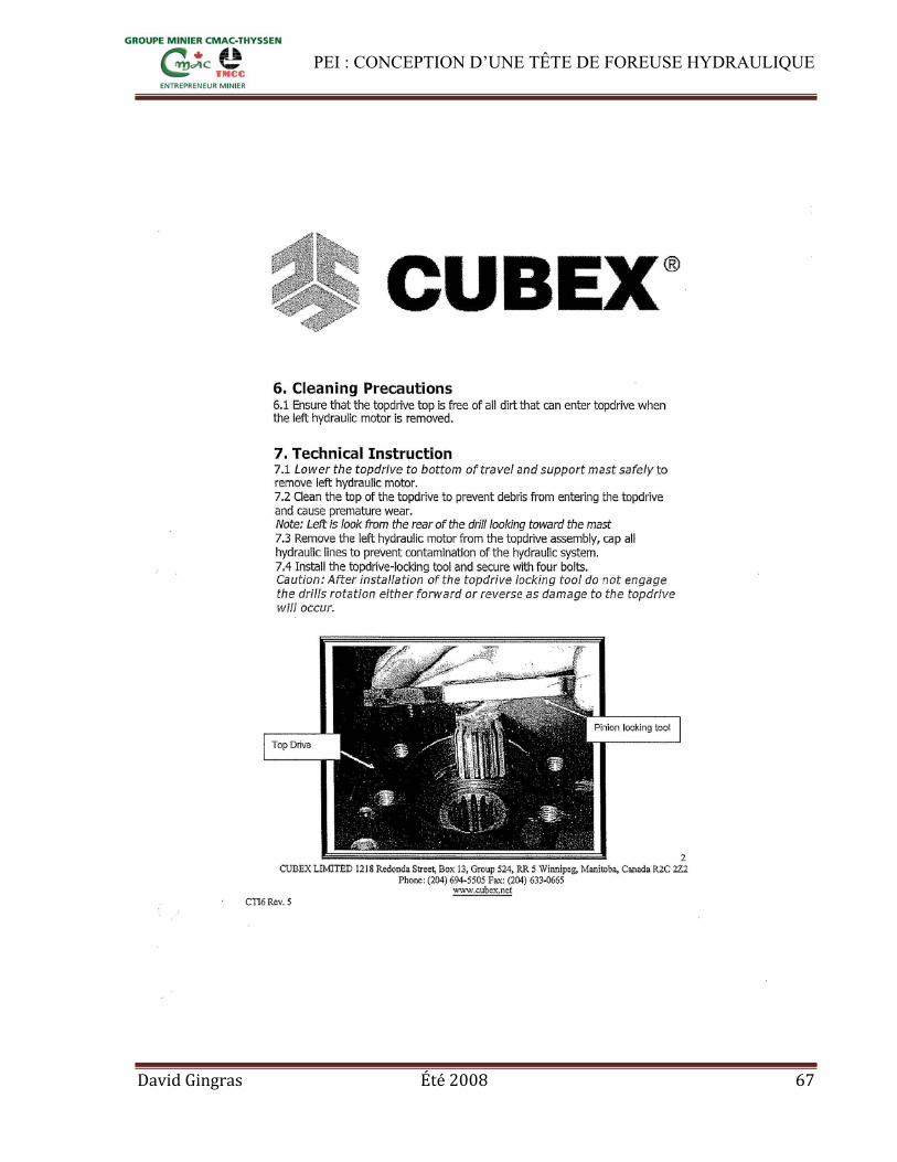
PEI : CONCEPTION D’UNE TÊTE DE FOREUSE HYDRAULIQUE
David Gingras Été 2008 67

PEI : CONCEPTION D’UNE TÊTE DE FOREUSE HYDRAULIQUE
David Gingras Été 2008 68

PEI : CONCEPTION D’UNE TÊTE DE FOREUSE HYDRAULIQUE
David Gingras Été 2008 69

PEI : CONCEPTION D’UNE TÊTE DE FOREUSE HYDRAULIQUE
David Gingras Été 2008 70

PEI : CONCEPTION D’UNE TÊTE DE FOREUSE HYDRAULIQUE
David Gingras Été 2008 71

PEI : CONCEPTION D’UNE TÊTE DE FOREUSE HYDRAULIQUE
David Gingras Été 2008 72

PEI : CONCEPTION D’UNE TÊTE DE FOREUSE HYDRAULIQUE
David Gingras Été 2008 73

PEI : CONCEPTION D’UNE TÊTE DE FOREUSE HYDRAULIQUE
David Gingras Été 2008 74

PEI : CONCEPTION D’UNE TÊTE DE FOREUSE HYDRAULIQUE
David Gingras Été 2008 75

PEI : CONCEPTION D’UNE TÊTE DE FOREUSE HYDRAULIQUE
David Gingras Été 2008 76

PEI : CONCEPTION D’UNE TÊTE DE FOREUSE HYDRAULIQUE
David Gingras Été 2008 77

PEI : CONCEPTION D’UNE TÊTE DE FOREUSE HYDRAULIQUE
David Gingras Été 2008 78
PEI : CONCEPTION D’UNE TÊTE DE FOREUSE HYDRAULIQUE
David Gingras Été 2008 79

PEI : CONCEPTION D’UNE TÊTE DE FOREUSE HYDRAULIQUE
David Gingras Été 2008 80

PEI : CONCEPTION D’UNE TÊTE DE FOREUSE HYDRAULIQUE
David Gingras Été 2008 81

PEI : CONCEPTION D’UNE TÊTE DE FOREUSE HYDRAULIQUE
David Gingras Été 2008 82

PEI : CONCEPTION D’UNE TÊTE DE FOREUSE HYDRAULIQUE
David Gingras Été 2008 83
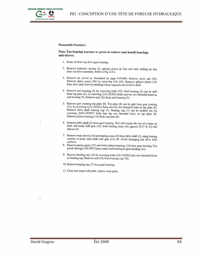
PEI : CONCEPTION D’UNE TÊTE DE FOREUSE HYDRAULIQUE
David Gingras Été 2008 84

PEI : CONCEPTION D’UNE TÊTE DE FOREUSE HYDRAULIQUE
David Gingras Été 2008 85

PEI : CONCEPTION D’UNE TÊTE DE FOREUSE HYDRAULIQUE
David Gingras Été 2008 86

PEI : CONCEPTION D’UNE TÊTE DE FOREUSE HYDRAULIQUE
David Gingras Été 2008 87

PEI : CONCEPTION D’UNE TÊTE DE FOREUSE HYDRAULIQUE
David Gingras Été 2008 88

PEI : CONCEPTION D’UNE TÊTE DE FOREUSE HYDRAULIQUE
David Gingras Été 2008 89

PEI : CONCEPTION D’UNE TÊTE DE FOREUSE HYDRAULIQUE
David Gingras Été 2008 90

PEI : CONCEPTION D’UNE TÊTE DE FOREUSE HYDRAULIQUE
David Gingras Été 2008 91

PEI : CONCEPTION D’UNE TÊTE DE FOREUSE HYDRAULIQUE
David Gingras Été 2008 92

PEI : CONCEPTION D’UNE TÊTE DE FOREUSE HYDRAULIQUE
David Gingras Été 2008 93

PEI : CONCEPTION D’UNE TÊTE DE FOREUSE HYDRAULIQUE
David Gingras Été 2008 94

PEI : CONCEPTION D’UNE TÊTE DE FOREUSE HYDRAULIQUE
David Gingras Été 2008 95

PEI : CONCEPTION D’UNE TÊTE DE FOREUSE HYDRAULIQUE
David Gingras Été 2008 96
Annexe C: Étude fait sur Excel portant sur le design de la transmission

PEI : CONCEPTION D’UNE TÊTE DE FOREUSE HYDRAULIQUE
David Gingras Été 2008 97

PEI : CONCEPTION D’UNE TÊTE DE FOREUSE HYDRAULIQUE
David Gingras Été 2008 98
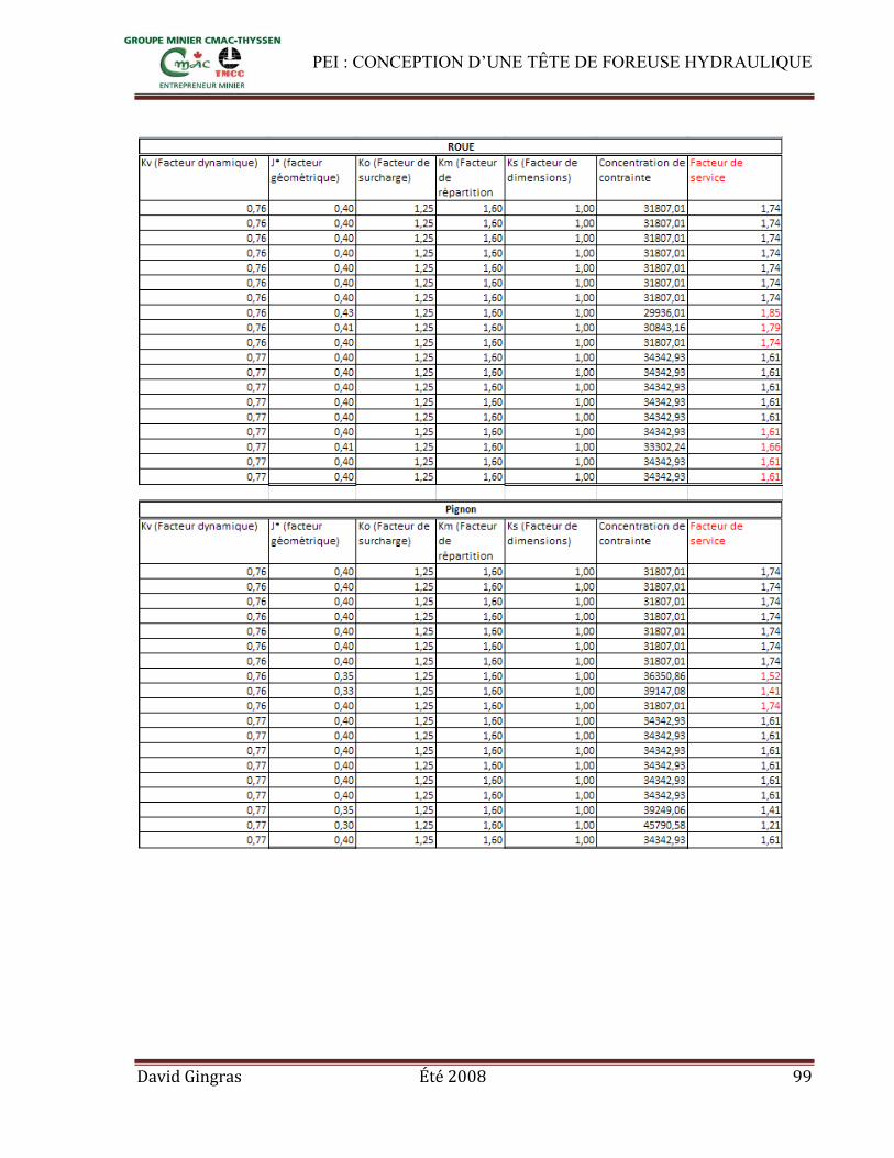
PEI : CONCEPTION D’UNE TÊTE DE FOREUSE HYDRAULIQUE
David Gingras Été 2008 99

PEI : CONCEPTION D’UNE TÊTE DE FOREUSE HYDRAULIQUE
David Gingras Été 2008 100

PEI : CONCEPTION D’UNE TÊTE DE FOREUSE HYDRAULIQUE
David Gingras Été 2008 101
Annexe D: Théories sur les facteurs de résistance et les dimensions des engrenages

PEI : CONCEPTION D’UNE TÊTE DE FOREUSE HYDRAULIQUE
David Gingras Été 2008 102

PEI : CONCEPTION D’UNE TÊTE DE FOREUSE HYDRAULIQUE
David Gingras Été 2008 103

PEI : CONCEPTION D’UNE TÊTE DE FOREUSE HYDRAULIQUE
David Gingras Été 2008 104

PEI : CONCEPTION D’UNE TÊTE DE FOREUSE HYDRAULIQUE
David Gingras Été 2008 105

PEI : CONCEPTION D’UNE TÊTE DE FOREUSE HYDRAULIQUE
David Gingras Été 2008 106

PEI : CONCEPTION D’UNE TÊTE DE FOREUSE HYDRAULIQUE
David Gingras Été 2008 107

PEI : CONCEPTION D’UNE TÊTE DE FOREUSE HYDRAULIQUE
David Gingras Été 2008 108

PEI : CONCEPTION D’UNE TÊTE DE FOREUSE HYDRAULIQUE
David Gingras Été 2008 109
Annexe E: Dessins de détails
(Il est fort probable que les dessins subissent des modifications)

David Gingras Été 2008 110

David Gingras Été 2008 111

David Gingras Été 2008 112

David Gingras Été 2008 113

David Gingras Été 2008 114

David Gingras Été 2008 115

David Gingras Été 2008 116

David Gingras Été 2008 117

David Gingras Été 2008 118

David Gingras Été 2008 119

David Gingras Été 2008 120

David Gingras Été 2008 121
Annexe F : Documentation sur le moteur TG335

David Gingras Été 2008 122

David Gingras Été 2008 123

David Gingras Été 2008 124

David Gingras Été 2008 125
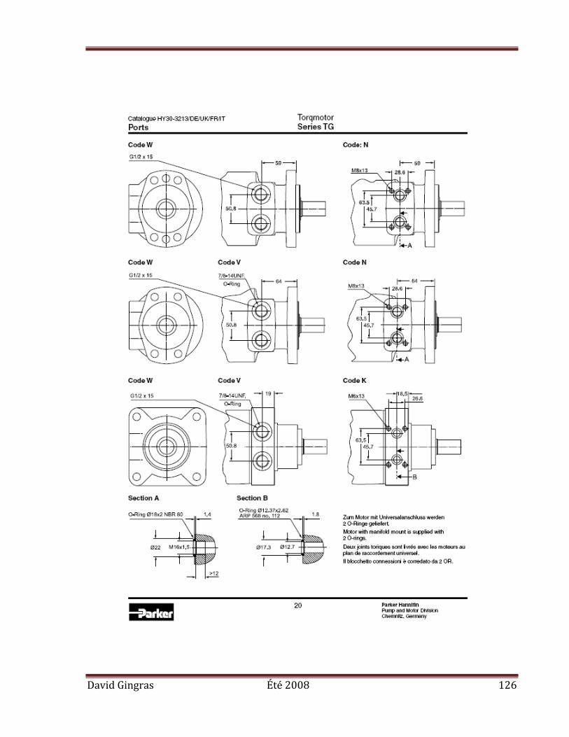
David Gingras Été 2008 126
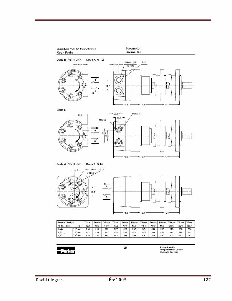
David Gingras Été 2008 127

David Gingras Été 2008 128

David Gingras Été 2008 129

David Gingras Été 2008 130

David Gingras Été 2008 131

David Gingras Été 2008 132

David Gingras Été 2008 133
Annexe G: Informations sur les roulements NTN

3. Load Rating and Life3.1 Bearing life
Even in bearings operating under normal conditions, thesurfaces of the raceway and rolling elements areconstantly being subjected to repeated compressivestresses which causes flaking of these surfaces to occur.This flaking is due to material fatigue and will eventuallycause the bearings to fail. The effective life of a bearingis usually defined in terms of the total number ofrevolutions a bearing can undergo before flaking of eitherthe raceway surface or the rolling element surfacesoccurs.
Other causes of bearing failure are often attributed toproblems such as seizing, abrasions, cracking, chipping,scuffing, rust, etc. However, these so called "causes" ofbearing failure are usually themselves caused byimproper installation, insufficient or improper lubrication,faulty sealing or inaccurate bearing selection. Since theabove mentioned "causes" of bearing failure can beavoided by taking the proper precautions, and are notsimply caused by material fatigue, they are consideredseparately from the flaking aspect.
3.2 Basic rating life and basic dynamic load ratingA group of seemingly identical bearings when subjected
to identical load and operating conditions will exhibit awide diversity in their durability.
This "life" disparity can be accounted for by thedifference in the fatigue of the bearing material itself.This disparity is considered statistically when calculatingbearing life, and the basic rating life is defined as follows.
The basic rating life is based on a 90% statistical modelwhich is expressed as the total number of revolutions90% of the bearings in an identical group of bearingssubjected to identical operating conditions will attain orsurpass before flaking due to material fatigue occurs. Forbearings operating at fixed constant speeds, the basicrating life (90% reliability) is expressed in the total numberof hours of operation.
Basic dynamic load rating expresses a rolling bearing'scapacity to support a dynamic load. The basic dynamicload rating is the load under which the basic rating life ofthe bearing is 1 million revolutions. This is expressed aspure radial load for radial bearings and pure axial load forthrust bearings. These are referred to as "basic dynamicload rating (Cr)" and "basic dynamic axial load rating (Ca)."The basic dynamic load ratings given in the bearingtables of this catalog are for bearings constructed of NTNstandard bearing materials, using standard manufacturingtechniques.
The relationship between the basic rating life, the basicdynamic load rating and the bearing load is given informula.
For ball bearings: L10=(C)
3……………(3.1)
P
For roller bearings: L10=(C)
10/3…………(3.2)
P
where,L10 : Basic rating life 106 revolutionsC : Basic dynamic load rating, N {kgf}
(Cr: radial bearings, Ca: thrust bearings)P : Equivalent dynamic load, N {kgf}
(Pr: radial bearings, Pa: thrust bearings)n : Rotational speed, min-1
The relationship between Rotational speed n and speedfactor fn as well as the relation between the basic ratinglife L10h and the life factor fn is shown in Table 3.1 andFig. 3.1.
A-17
●Load Rating and Life
40,000
4.6
60,000
80,000
30,000
20,000
15,000
3
10,0002.5
8,000
6,000
4,000
3,000
2,000
1.9
3.5
4.5
2
4
1.8
1.7
1.6
1.5
1.41,500
1.3
1.21,000
1.1
900
800
700
600
500
4000.95
1.0
0.90
300 0.85
0.80
0.76200
100
0.6
60,000
40,000
0.106
30,000
0.12
0.1420,000
0.1615,000
0.1810,000
0.208,000
0.22
0.24
0.26
0.28
6,000
4,000
3,000
2,0000.30
1,500
0.351,000
0.4800
600
0.5
400
300
200
150
0.7
80
600.8
0.940
301.0
1.1
1.3
20
15
1.4
1.2
1.4410
60,000
5.480,000
4.5
5
40,000
430,000
3.520,000
15,0003
2.5
10,000
6,000
24,000
3,000
2,000
1.9
1.8
1.7
1.6
1.5
1,5001.4
1.3
1.21,000
800
900
700 1.1
1.0
600
500
4000.95
0.90
0.85300
0.80
0.75
0.742001.4910
40,000
60,000
30,0000.10
0.082
0.09
0.12
0.14
20,000
15,000
0.16
0.18
10,0008,000
8,000
6,000
4,000
3,000
2,000
1,500
1,000800
600
400
300
200
150
0.20
0.22
0.24
0.26
0.28
0.30
0.35
0.4
0.5
0.6
0.7
0.8
10080
60
40
30
20
0.9
1.0
1.1
1.2
1.3
1.4
15
fnn L10h
min-1 hfh n L10hfn
min-1 hfh
Ball bearings Roller bearings
Fig. 3.1 Bearing life rating scale
Classification Ball bearing Roller bearing
Basic rating lifeL10h h
Life factorfh
Speed factorfn
60n106
( )P
C
( )n33.3
fnP
C fnP
C
= 500 fh3
60n106
( )P
C= 500 fh
10/310/3
1/3
( )n33.3 3/10
3
Table 3.1 Correlation of bearing basic rating life, life factor, and speed factor
134

When several bearings are incorporated in machinesor equipment as complete units, all the bearings in theunit are considered as a whole when computing bearinglife (see formula 3.3).
1L =( 1 + 1 + … 1 )
1/e…………(3.3)
L1e
L2e
Lne
where,L : Total basic rating life of entire unit, h
L1 , L2 …Ln: Basic rating life of individual bearings, 1, 2,…n, h
e = 10/9....................For ball bearingse = 9/8......................For roller bearings
When the load conditions vary at regular intervals, thelife can be given by formula (3.4).
Lm =(Φ1 +Φ2 +…
Φ j )
-1……………(3.4)
L1 L2 L j
where,L m : Total life of bearingΦ j : Frequency of individual load conditions
(ΣΦ j = 1)L j : Life under individual conditions
If equivalent load P and rotational speed n areoperating conditions of the bearing, basic rated dynamicload C that satisfies required life of the bearing isdetermined using Table 3.1 and formula (3.5). Bearingsthat satisfy the required C can be selected from thebearing dimensions table provided in the catalog.
fhC = P ――……………………………………(3.5)
fn
3.3 Adjusted rating lifeThe basic bearing rating life (90% reliability factor) can
be calculated through the formulas mentioned earlier inSection 3.2. However, in some applications a bearing lifefactor of over 90% reliability may be required. To meetthese requirements, bearing life can be lengthened by theuse of specially improved bearing materials ormanufacturing process. Bearing life is also sometimesaffected by operating conditions such as lubrication,temperature and rotational speed.
Basic rating life adjusted to compensate for this iscalled "adjusted rating life," and is determined usingformula (3.6).
Lna= a1・a2・a3・L10…(3.6)where,
Lna : Adjusted rating life in millions of revolutions (106)
a1 : Reliability factora2 : Bearing characteristics factora3 : Operating conditions factor
3.3.1 Reliability factor a1
The value of reliability factor a1 is provided in Table 3.2for reliability of 90% or greater.
3.3.2 Bearing characteristics factor a2
Bearing characteristics concerning life vary according tobearing material, quality of material and if using specialmanufacturing process. In this case, life is adjusted usingbearing characteristics factor a2.
The basic dynamic load ratings listed in the catalog arebased on NTN's standard material and process,therefore, the adjustment factor a2 =1. a2 > 1 may beused for specially enhanced materials and manufacturingmethods.If this applies, consult with NTN Engineering.
Dimensions change significantly if bearings made ofhigh carbon chrome bearing steel with conventional heattreatment are used at temperatures in excess of 120˚Cfor an extended period of time. NTN Engineeringtherefore offers a bearing for high-temperatureapplications specially treated to stabilize dimensions atthe maximum operating temperature (TS treatment). Thetreatment however makes the bearing softer and affectslife of the bearing. Life is adjusted by multiplying by thevalues given in Table 3.3.
3.3.3 Operating conditions factor a3
Operating conditions factor a3 is used to compensate forwhen lubrication condition worsens due to rise intemperature or rotational speed, lubricant deteriorates, orbecomes contaminated with foreign matter.
Generally speaking, when lubricating conditions aresatisfactory, the a3 factor has a value of one; and whenlubricating conditions are exceptionally favorable, and allother operating conditions are normal, a3 can have avalue greater than one. a3 is however less than 1 in thefollowing cases:
A-18
●Load Rating and Life
Reliability % Ln Reliability factor a1
90
95
96
97
98
99
L10
L5
L4
L3
L2
L1
1.00
0.62
0.53
0.44
0.33
0.21
Table 3.2 Reliability factor a1
SymbolMax. operating temperature (C˚)
Bearing characteristics factor a2
TS3
TS4
200
250
0.73
0.48
TS2 160 1.00
Table 3.3 Treatment for stabilizing dimensions
135

¡Dynamic viscosity of lubricating oil is too low for bearingoperating temperature(13 mm2/s or less for ball bearings, 20 mm2/s for rollerbearings)
¡Rotational speed is particularly low(If sum of rotational speed n min-1 and rolling elementpitch diameter Dpw mm is Dpw・n< 10,000)
¡Bearing operating temperature is too highIf bearing operating temperature is too high, theraceway becomes softened, thereby shortening life.Life is adjusted by multiplying by the values given inFig. 3.2 as the operating condition factor according tooperating temperature. This however does not apply tobearings that have been treated to stabilizedimensions.
¡Lubricant contaminated with foreign matter or moistureIf using special operating condition, consult with NTNEngineering. Even if a2> 1 is used for speciallybearings made of enhanced materials or produced byspecial manufacturing methods, a2×a3< 1 is used iflubricating conditions are not favorable.
A-19
●Load Rating and Life
Table 3.4 Machine application and requisite life (reference)
~4 4~12 12~30 30~60 60~
Machine application and requisite life (reference) L10h ×103 hServiceclassification
Machines used for shortperiods or used only occasionally
Short period or intermittentuse, but with high reliabilityrequirements
Machines not in constantuse, but used for longperiods
Machines in constant useover 8 hours a day
24 hour continuousoperation, non-interruptable
¡Household appliances¡Electric hand tools
¡Medical appliances¡Measuring instruments
¡Automobiles¡Two-wheeled vehicles
¡Farm machinery¡Office equipment
¡Home air- conditioning motor¡Construction equipment¡Elevators¡Cranes
¡Small motors¡Buses/trucks¡General gear drives¡Woodworking machines
¡Rolling mills¡Escalators ¡Conveyors¡Centrifuges
¡Crane (sheaves)
¡Machine spindles¡Industrial motors¡Crushers¡Vibrating screens
¡Railway vehicle axles ¡Air conditioners¡Large motors¡Compressor pumps
¡Main gear drives¡Rubber/plastic¡Calender rolls¡Printing machines
¡Locomotive axles¡Traction motors¡Mine hoists¡Pressed flywheels
¡Papermaking machines¡Propulsion equipment for marine vessels
¡Water supply equipment¡Mine drain pumps/ventilators¡Power generating equipment
Fig. 3.2 Operating conditions factor according to operating temperature
300250200150100
1.0
0.8
0.6
0.4
0.2
Ope
ratin
g co
nditi
ons
fact
or
a3
Operating temperature ˚C
When a super heavy load is applied, harmful plasticdistortion could be produced on the contact surfaces ofthe rolling elements and raceway. The formulae fordetermining basic rating life (3.1, 3.2, and 3.6) do notapply if Pr exceeds either Cor (Basic static load rating) or0.5 Cr for radial bearings, or if Pa exceeds 0.5 Ca for thrustbearings.
3.4 Machine applications and requisite lifeWhen selecting a bearing, it is essential that the
requisite life of the bearing be established in relation tothe operating conditions. The requisite life of the bearingis usually determined by the type of machine in which thebearing will be used, and duration of service andoperational reliability requirements. A general guide tothese requisite life criteria is shown in Table 3.4. Whendetermining bearing size, the fatigue life of the bearing isan important factor; however, besides bearing life, thestrength and rigidity of the shaft and housing must also betaken into consideration.
3.5 Basic static load ratingWhen stationary rolling bearings are subjected to static
loads, they suffer from partial permanent deformation ofthe contact surfaces at the contact point between therolling elements and the raceway. The amount ofdeformity increases as the load increases, and if thisincrease in load exceeds certain limits, the subsequentsmooth operation of the bearings is impaired.
It has been found through experience that a permanentdeformity of 0.0001 times the diameter of the rollingelement, occurring at the most heavily stressed contactpoint between the raceway and the rolling elements, canbe tolerated without any impairment in running efficiency.
136

●Load Rating and Life
Table 3.5 Minimum safety factor values S0
2
1
0.5
3
1.5
1
Operating conditions
High rotational accuracy demand
Ballbearings
Rollerbearings
Normal rotating accuracy demand(Universal application)
Slight rotational accuracydeterioration permitted(Low speed, heavy loading, etc.)
Note 1: For spherical thrust roller bearings, min. S0 value=4.2: For shell needle roller bearings, min. S0 value=3.3: When vibration and/or shock loads are present, a load factor
based on the shock load needs to be included in the P0 max value.4: If a large axial load is applied to deep groove ball bearings or
angular ball bearings, the contact oval may exceed the raceway surface. For more information, please contact NTN Engineering.
The basic static load rating refers to a fixed static loadlimit at which a specified amount of permanentdeformation occurs. It applies to pure radial loads forradial bearings and to pure axial loads for thrust bearings.The maximum applied load values for contact stressoccurring at the rolling element and raceway contactpoints are given below.
For ball bearings 4,200 MPa {428kgf/mm2}For self-aligning ball bearings 4,600 MPa {469kgf/mm2}For roller bearings 4,000 MPa {408kgf/mm2}
Referred to as "basic static radial load rating" for radialbearings and "basic static axial load rating" for thrustbearings, basic static load rating is expressed as Cor orCoa respectively and is provided in the bearing dimensionstable.
3.6 Allowable static equivalent loadGenerally the static equivalent load which can be
permitted (See page A-25) is limited by the basic staticrating load as stated in Section 3.5. However, dependingon requirements regarding friction and smooth operation,these limits may be greater or lesser than the basic staticrating load.
A-20
This is generally determined by taking the safety factorSo given in Table 3.5 and formula (3.7) into account.
So =Co/Po…(3.7)
where,So : Safety factorCo : Basic static load rating, N {kgf}
(radial bearings: Cor, thrust bearings: Coa)Po : Static equivalent load, N {kgf}
(radial: Por, thrust: Coa)
137

B-12
40
45
50
55
60
d 40~60mm
52 7 0.3 0.3 5.10 4.40 520 445 16.3 12 000 14 000 ― 6 700 6808 ZZ LLB ― LLU62 12 0.6 0.5 12.2 8.90 1 240 910 15.8 11 000 13 000 ― 6 300 6908 ZZ LLB ― LLU68 9 0.3 ― 12.6 9.65 1 290 985 16.0 10 000 12 000 ― ― 16008 ― ― ― ―68 15 1 0.5 16.8 11.5 1 710 1 170 15.2 10 000 12 000 7 300 6 100 6008 ZZ LLB LLH LLU80 18 1.1 0.5 29.1 17.8 2 970 1 820 14.0 8 700 10 000 6 700 5 600 6208 ZZ LLB LLH LLU90 23 1.5 0.5 40.5 24.0 4 150 2 450 13.2 7 800 9 200 6 400 5 300 6308 ZZ LLB LLH LLU
110 27 2 ― 63.5 36.5 6 500 3 750 12.3 7 000 8 200 ― ― 6408 ― ― ― ―
58 7 0.3 0.3 5.35 4.95 550 500 16.1 11 000 12 000 ― 5 900 6809 ZZ LLB ― LLU68 12 0.6 0.5 13.1 10.4 1 330 1 060 16.1 9 800 12 000 ― 5 600 6909 ZZ LLB ― LLU75 10 0.6 ― 12.9 10.5 1 320 1 070 16.2 9 200 11 000 ― ― 16009 ― ― ― ―75 16 1 0.5 21.0 15.1 2 140 1 540 15.3 9 200 11 000 6 500 5 400 6009 ZZ LLB LLH LLU85 19 1.1 0.5 32.5 20.4 3 350 2 080 14.1 7 800 9 200 6 200 5 200 6209 ZZ LLB LLH LLU
100 25 1.5 0.5 53.0 32.0 5 400 3 250 13.1 7 000 8 200 5 600 4 700 6309 ZZ LLB LLH LLU120 29 2 ― 77.0 45.0 7 850 4 600 12.1 6 300 7 400 ― ― 6409 ― ― ― ―
65 7 0.3 0.3 6.60 6.10 670 620 16.1 9 600 11 000 ― 5 300 6810 ZZ LLB ― LLU72 12 0.6 0.5 13.4 11.2 1 370 1 140 16.3 8 900 11 000 ― 5 100 6910 ZZ LLB ― LLU80 10 0.6 ― 13.2 11.3 1 350 1 150 16.4 8 400 9 800 ― ― 16010 ― ― ― ―80 16 1 0.5 21.8 16.6 2 230 1 690 15.5 8 400 9 800 6 000 5 000 6010 ZZ LLB LLH LLU90 20 1.1 0.5 35.0 23.2 3 600 2 370 14.4 7 100 8 300 5 700 4 700 6210 ZZ LLB LLH LLU
110 27 2 0.5 62.0 38.5 6 300 3 900 13.2 6 400 7 500 5 000 4 200 6310 ZZ LLB LLH LLU130 31 2.1 ― 83.0 49.5 8 450 5 050 12.5 5 700 6 700 ― ― 6410 ― ― ― ―
72 9 0.3 0.3 8.80 8.10 900 825 16.2 8 700 10 000 ― 4 800 6811 ZZ LLB ― LLU80 13 1 0.5 16.0 13.3 1 630 1 350 16.2 8 200 9 600 ― 4 600 6911 ZZ LLB ― LLU90 11 0.6 ― 18.6 15.3 1 900 1 560 16.2 7 700 9 000 ― ― 16011 ― ― ― ―90 18 1.1 0.5 28.3 21.2 2 880 2 170 15.3 7 700 9 000 ― 4 500 6011 ZZ LLB ― LLU
100 21 1.5 0.5 43.5 29.2 4 450 2 980 14.3 6 400 7 600 ― 4 300 6211 ZZ LLB ― LLU120 29 2 0.5 71.5 45.0 7 300 4 600 13.2 5 800 6 800 ― 3 900 6311 ZZ LLB ― LLU140 33 2.1 ― 89.0 54.0 9 050 5 500 12.7 5 200 6 100 ― ― 6411 ― ― ― ―
78 10 0.3 0.3 11.5 10.6 1 170 1 080 16.3 8 000 9 400 ― 4 400 6812 ZZ LLB ― LLU85 13 1 0.5 16.4 14.3 1 670 1 450 16.4 7 600 8 900 ― 4 300 6912 ZZ LLB ― LLU95 11 0.6 ― 20.0 17.5 2 040 1 780 16.3 7 000 8 300 ― ― 16012 ― ― ― ―95 18 1.1 0.5 29.5 23.2 3 000 2 370 15.6 7 000 8 300 ― 4 100 6012 ZZ LLB ― LLU
110 22 1.5 0.5 52.5 36.0 5 350 3 700 14.3 6 000 7 000 ― 3 800 6212 ZZ LLB ― LLU130 31 2.1 0.5 82.0 52.0 8 350 5 300 13.2 5 400 6 300 ― 3 600 6312 ZZ LLB ― LLU150 35 2.1 ― 102 64.5 10 400 6 550 12.6 4 800 5 700 ― ― 6412 ― ― ― ―
●Deep Groove Ball Bearings
Shielded type(ZZ)
Non-contactsealed type(LLB, LLF)
Contactsealed type
(LLU)
Low torquesealed type
(LLH)
Open type
B
r
r
φD φd
1)Smallest allowable dimension for chamfer dimension r.
Boundary dimensions Basic load ratings Factor Limiting speeds Bearing numbersdynamic static dynamic static
min-1 non- lowmm kN kgf grease oil contact torque contact
rNS open type open type open shielded sealed sealed sealedd D B rs min
1) min Cr Cor Cr Cor fo ZZ LLB Z LB LLH LLU type type type type type
138

B-13
N NR 50.7 1.3 0.95 0.25 54.8 0.85 42 43 50 55.5 1.9 0.9 0.3 0.3 0.033N NR 60.7 1.7 0.95 0.25 64.8 0.85 44 45 58 65.5 2.3 0.9 0.6 0.5 0.11― ― ― ― ― ― ― ― 42 ― 66 ― ― ― 0.3 ― 0.125N NR 64.82 2.49 1.9 0.6 74.6 1.7 45 47 63 76 3.8 1.7 1 0.5 0.19N NR 76.81 3.28 1.9 0.6 86.6 1.7 46.5 51 73.5 88 4.6 1.7 1 0.5 0.366N NR 86.79 3.28 2.7 0.6 96.5 2.46 48 54 82 98 5.4 2.5 1.5 0.5 0.63― ― ― ― ― ― ― ― 49 ― 101 ― ― ― 2.0 ― 1.23
N NR 56.7 1.3 0.95 0.25 60.8 0.85 47 48 56 61.5 1.9 0.9 0.3 0.3 0.04N NR 66.7 1.7 0.95 0.25 70.8 0.85 49 51 64 72 2.3 0.9 0.6 0.5 0.128― ― ― ― ― ― ― ― 49 ― 71 ― ― ― 0.6 ― 0.171N NR 71.83 2.49 1.9 0.6 81.6 1.7 50 52.5 70 83 3.8 1.7 1 0.5 0.237N NR 81.81 3.28 1.9 0.6 91.6 1.7 51.5 55.5 78.5 93 4.6 1.7 1 0.5 0.398N NR 96.8 3.28 2.7 0.6 106.5 2.46 53 61.5 92 108 5.4 2.5 1.5 0.5 0.814― ― ― ― ― ― ― ― 54 ― 111 ― ― ― 2 ― 1.53
N NR 63.7 1.3 0.95 0.25 67.8 0.85 52 54 63 68.5 1.9 0.9 0.3 0.3 0.052N NR 70.7 1.7 0.95 0.25 74.8 0.85 54 55.5 68 76 2.3 0.9 0.6 0.5 0.132― ― ― ― ― ― ― ― 54 ― 76 ― ― ― 0.6 ― 0.18N NR 76.81 2.49 1.9 0.6 86.6 1.7 55 57.5 75 88 3.8 1.7 1 0.5 0.261N NR 86.79 3.28 2.7 0.6 96.5 2.46 56.5 60 83.5 98 5.4 2.5 1 0.5 0.454N NR 106.81 3.28 2.7 0.6 116.6 2.46 59 68.5 101 118 5.4 2.5 2 0.5 1.07― ― ― ― ― ― ― ― 61 ― 119 ― ― ― 2 ― 1.88
N NR 70.7 1.7 0.95 0.25 74.8 0.85 57 59 70 76 2.3 0.9 0.3 0.3 0.083N NR 77.9 2.1 1.3 0.4 84.4 1.12 60 61.5 75 86 2.9 1.2 1 0.5 0.18― ― ― ― ― ― ― ― 59 ― 86 ― ― ― 0.6 ― 0.258N NR 86.79 2.87 2.7 0.6 96.5 2.46 61.5 64 83.5 98 5 2.5 1 0.5 0.388N NR 96.8 3.28 2.7 0.6 106.5 2.46 63 67 92 108 5.4 2.5 1.5 0.5 0.601N NR 115.21 4.06 3.1 0.6 129.7 2.82 64 74 111 131.5 6.5 2.9 2 0.5 1.37― ― ― ― ― ― ― ― 66 ― 129 ― ― ― 2 ― 2.29
N NR 76.2 1.7 1.3 0.4 82.7 1.12 62 64.5 76 84 2.5 1.2 0.3 0.3 0.106N NR 82.9 2.1 1.3 0.4 89.4 1.12 65 66.5 80 91 2.9 1.2 1 0.5 0.193― ― ― ― ― ― ― ― 64 ― 91 ― ― ― 0.6 ― 0.283N NR 91.82 2.87 2.7 0.6 101.6 2.46 66.5 69 88.5 103 5 2.5 1 0.5 0.414N NR 106.81 3.28 2.7 0.6 116.6 2.46 68 75 102 118 5.4 2.5 1.5 0.5 0.783N NR 125.22 4.06 3.1 0.6 139.7 2.82 71 80.5 119 141.5 6.5 2.9 2 0.5 1.73― ― ― ― ― ― ― ― 71 ― 139 ― ― ― 2 ― 2.77
Bearing Snap ring groove Snap ring Abutment and fillet dimensions Mass4)numbers dimensions dimensions
mm mm mmsnap2) snap2)
kg
ring ring D1 a b ro D2 f da Da DX CY CZ ras rNas
groove max max min max max max min max3) max (approx.) max min max max (approx.)
●Deep Groove Ball Bearings
a
b
ro ro
f
φD2
rNa
CY
ra
φdaφDaφDXφdφD1 φD
B
rrN
r
CZ
With snap ringWith snap ring groove
0.1720.3450.6891.031.382.073.455.176.89
0.190.220.260.280.300.340.380.420.44
1 0 0.56
2.301.991.711.551.451.311.151.041.00
Fa
FreX Y X Y
≦efo・Fa
Cor
Fa
Fr>e
Dynamic equivalent radial loadPr=XFr+YFa
Static equivalent radial loadPor=0.6Fr+0.5Fa
When Por<Fr use Por=Fr
2)Sealed and shielded bearings are also available. 3)This dimension applies to sealed and shielded bearings. 4)Does not include bearings with snap rings.139

B-196
d 133.350~196.850mm
133.350
136.525
139.700
142.875
146.050
152.400
158.750
165.100
170.000
177.800
180.000
190.000
196.850
190.500 39.688 39.688 33.338 236 475 24 100 48 500 1 700 2 300196.850 46.038 46.038 38.100 310 550 31 500 56 500 1 700 2 200196.850 46.038 46.038 38.100 310 550 31 500 56 500 1 700 2 200215.900 47.625 47.625 34.925 320 540 32 500 55 000 1 600 2 100234.950 63.500 63.500 49.212 525 825 53 500 84 000 1 500 2 000
190.500 39.688 39.688 33.338 236 475 24 100 48 500 1 700 2 300228.600 57.150 57.150 44.450 445 735 45 500 75 000 1 500 2 000
215.900 47.625 47.625 34.925 320 540 32 500 55 000 1 600 2 100228.600 57.150 57.150 44.450 445 735 45 500 75 000 1 500 2 000254.000 66.675 66.675 47.625 550 910 56 000 92 500 1 400 1 800
200.025 41.275 39.688 34.130 239 490 24 300 50 000 1 600 2 100200.025 41.275 39.688 34.130 239 490 24 300 50 000 1 600 2 100
193.675 28.575 28.575 23.020 165 340 16 800 35 000 1 600 2 200254.000 66.675 66.675 47.625 550 910 56 000 92 500 1 400 1 800
192.088 25.000 24.000 19.000 130 261 13 200 26 700 1 600 2 100222.250 46.830 46.830 34.925 315 585 32 000 60 000 1 500 2 000
205.583 23.812 23.812 18.258 126 247 12 900 25 200 1 500 2 000225.425 41.275 39.688 33.338 254 555 25 900 56 500 1 400 1 900
225.425 41.275 39.688 33.338 254 555 25 900 56 500 1 400 1 900
230.000 39.000 38.000 31.000 282 520 28 700 53 000 1 400 1 800
227.012 30.162 30.162 23.020 181 415 18 500 42 000 1 300 1 800247.650 47.625 47.625 38.100 340 690 35 000 70 500 1 300 1 700
250.000 47.000 45.000 37.000 370 710 37 500 72 500 1 300 1 700
260.000 46.000 44.000 36.500 365 720 37 000 73 500 1 200 1 600
241.300 23.812 23.017 17.462 160 330 16 300 33 500 1 200 1 600
Note: 1. Chamfer dimensions on the back face of the inner and outer rings of the bearing are larger than maximum values for installation dimensions ras and r1as. 2. Bearing numbers marked "# " designate J-series bearings. The tolerances of these bearings is listed in Table 6.6 on page A-42.
● Tapered Roller Bearings
Boundary dimensions Basic load ratings Limiting speedsdynamic static dynamic static
mm kN kgf min-1
d D T B C Cr Cor Cr Cor grease oil
Inch seriesJ series
T
C
φD
B
r1
φd
r
a
140

B-197
4T-48385/48320 148 142 177 184 3.5 3.3 4.0 0.32 1.87 1.03 3.644T-67390/67322 149 143 180 189 3.5 3.3 6.3 0.34 1.74 0.96 4.634T-67391/67322 157 143 180 189 8 3.3 6.3 0.34 1.74 0.96 4.594T-74525/74850 152 146 196 208 3.5 3.3 –2.21) 0.49 1.23 0.68 6.564T-95525/95925 166 148 209 217 9.7 3.3 14.0 0.37 1.62 0.89 11.3
4T-48393/48320 151 144 177 184 3.5 3.3 4.0 0.32 1.87 1.03 3.434T-896/892 156 150 205 216 3.5 3.3 6.0 0.42 1.43 0.78 9.07
4T-74550/74850 158 151 196 208 3.5 3.3 –2.21) 0.49 1.23 0.68 6.054T-898/892 160 153 205 216 3.5 3.3 6.0 0.42 1.43 0.78 8.764T-99550/99100 170 156 227 238 7 3.3 12.1 0.41 1.47 0.81 14.3
4T-48684/48620 166 151 185 193 8 3.3 3.1 0.34 1.78 0.98 3.854T-48685/48620 158 151 185 193 3.5 3.3 3.1 0.34 1.78 0.98 3.89
4T-36690/36620 155 153 182 188 1.5 1.5 –5.01) 0.37 1.63 0.90 2.274T-99575/99100 175 162 227 238 7 3.3 12.1 0.41 1.47 0.81 13.5
4T-L630349/L630310 162 158 183 187 2 2 –10.01) 0.42 1.44 0.79 1.534T-M231648/M231610 178 163 207 213 8 1.5 5.9 0.33 1.8 0.99 5.72
4T-L432349/L432310 168 166 195 199 1.5 1.5 –9.81) 0.37 1.61 0.88 1.894T-46780/46720 176 169 209 218 3.5 3.3 –2.61) 0.38 1.57 0.86 5.2
4T-46790/46720 181 174 209 218 3.5 3.3 –2.61) 0.38 1.57 0.86 4.69
# 4T-JHM534149/JHM534110 184 178 217 224 3 2.5 –4.71) 0.38 1.57 0.86 4.37
4T-36990/36920 188 186 214 221 1.5 1.5 –12.81) 0.44 1.36 0.75 2.924T-67790/67720 194 188 229 240 3.5 3.3 –4.81) 0.44 1.36 0.75 6.57
# 4T-JM736149/JM736110 196 190 232 243 3 2.5 –9.01) 0.48 1.25 0.69 6.76
# 4T-JM738249/JM738210 206 200 242 252 3 2.5 –10.91) 0.48 1.26 0.69 6.85
4T-LL639249/LL639210 205 203 232 236 1.5 1.5 –17.31) 0.42 1.44 0.79 2.07
1) "-" means that load center at outside on end of inner ring.
● Tapered Roller Bearings
Bearing numbers Abutment and fillet dimensions Load Constant Axial Masscenter load factors
mm mm kgras r1as
da db Da Db max max a e Y2 Yo (approx.)
r1a
ra
φda φDbφDa φdb
1 0 0.4 Y2
Fa
FrX Y X Y
≦eFa
Fr>e
staticPor=0.5Fr+YoFa
When Por<Fr use Por=Fr
For values of e, Y2 and Yo
see the table below.
Equivalent radial loaddynamicPr=XFr+YFa
141
Related Documents


![MODULE DES SCIENCES APPLIQUÉES - Bibliothèque …bibliotheque.uqat.ca/documents/rapportsa/95.pdf · Test No. 2– Application de la charge vers l’arrière [NSVAC 207 1(a)i(B)]](https://static.cupdf.com/doc/110x72/5b396e007f8b9abd438e5a12/module-des-sciences-appliquees-bibliotheque-test-no-2-application-de.jpg)