Comments? Send comments on the documentation by going to http://solvnet.synopsys.com, then clicking “Enter a Call to the Support Center.” Module Compiler ™ User Guide Version X-2005.09, September 2005

Welcome message from author
This document is posted to help you gain knowledge. Please leave a comment to let me know what you think about it! Share it to your friends and learn new things together.
Transcript

Comments?Send comments on the documentation by goingto http://solvnet.synopsys.com, then clicking “Enter a Call to the Support Center.”
Module Compiler™
User GuideVersion X-2005.09, September 2005

ii
Copyright Notice and Proprietary InformationCopyright © 2005 Synopsys, Inc. All rights reserved. This software and documentation contain confidential and proprietary information that is the property of Synopsys, Inc. The software and documentation are furnished under a license agreement and may be used or copied only in accordance with the terms of the license agreement. No part of the software and documentation may be reproduced, transmitted, or translated, in any form or by any means, electronic, mechanical, manual, optical, or otherwise, without prior written permission of Synopsys, Inc., or as expressly provided by the license agreement.
Right to Copy DocumentationThe license agreement with Synopsys permits licensee to make copies of the documentation for its internal use only. Each copy shall include all copyrights, trademarks, service marks, and proprietary rights notices, if any. Licensee must assign sequential numbers to all copies. These copies shall contain the following legend on the cover page:
“This document is duplicated with the permission of Synopsys, Inc., for the exclusive use of __________________________________________ and its employees. This is copy number __________.”
Destination Control StatementAll technical data contained in this publication is subject to the export control laws of the United States of America. Disclosure to nationals of other countries contrary to United States law is prohibited. It is the reader’s responsibility to determine the applicable regulations and to comply with them.
DisclaimerSYNOPSYS, INC., AND ITS LICENSORS MAKE NO WARRANTY OF ANY KIND, EXPRESS OR IMPLIED, WITH REGARD TO THIS MATERIAL, INCLUDING, BUT NOT LIMITED TO, THE IMPLIED WARRANTIES OF MERCHANTABILITY AND FITNESS FOR A PARTICULAR PURPOSE.
Registered Trademarks (®)Synopsys, AMPS, Arcadia, C Level Design, C2HDL, C2V, C2VHDL, Cadabra, Calaveras Algorithm, CATS, CRITIC, CSim, Design Compiler, DesignPower, DesignWare, EPIC, Formality, HSIM, HSPICE, Hypermodel, iN-Phase, in-Sync, Leda, MAST, Meta, Meta-Software, ModelTools, NanoSim, OpenVera, PathMill, Photolynx, Physical Compiler, PowerMill, PrimeTime, RailMill, RapidScript, Saber, SiVL, SNUG, SolvNet, Superlog, System Compiler, Testify, TetraMAX, TimeMill, TMA, VCS, Vera, and Virtual Stepper are registered trademarks of Synopsys, Inc.
Trademarks (™)Active Parasitics, AFGen, Apollo, Apollo II, Apollo-DPII, Apollo-GA, ApolloGAII, Astro, Astro-Rail, Astro-Xtalk, Aurora, AvanTestchip, AvanWaves, BCView, Behavioral Compiler, BOA, BRT, Cedar, ChipPlanner, Circuit Analysis, Columbia, Columbia-CE, Comet 3D, Cosmos, CosmosEnterprise, CosmosLE, CosmosScope, CosmosSE, Cyclelink, Davinci, DC Expert, DC Expert Plus, DC Professional, DC Ultra, DC Ultra Plus, Design Advisor, Design Analyzer, Design Vision, DesignerHDL, DesignTime, DFM-Workbench, Direct RTL, Direct Silicon Access, Discovery, DW8051, DWPCI, Dynamic Model Switcher, Dynamic-Macromodeling, ECL Compiler, ECO Compiler, EDAnavigator, Encore, Encore PQ, Evaccess, ExpressModel, Floorplan Manager, Formal Model Checker, FoundryModel, FPGA Compiler II, FPGA Express, Frame Compiler, Galaxy, Gatran, HANEX, HDL Advisor, HDL Compiler, Hercules, Hercules-Explorer, Hercules-II, Hierarchical
Optimization Technology, High Performance Option, HotPlace, HSIMplus
, HSPICE-Link, i-Virtual Stepper, iN-Tandem, Integrator, Interactive Waveform Viewer, Jupiter, Jupiter-DP, JupiterXT, JupiterXT-ASIC, JVXtreme, Liberty, Libra-Passport, Libra-Visa, Library Compiler, Magellan, Mars, Mars-Rail, Mars-Xtalk, Medici, Metacapture, Metacircuit, Metamanager, Metamixsim, Milkyway, ModelSource, Module Compiler, MS-3200, MS-3400, Nova Product Family, Nova-ExploreRTL, Nova-Trans, Nova-VeriLint, Nova-VHDLlint, Optimum Silicon, Orion_ec, Parasitic View, Passport, Planet, Planet-PL, Planet-RTL, Polaris, Polaris-CBS, Polaris-MT, Power Compiler, PowerCODE, PowerGate, ProFPGA, ProGen, Prospector, Protocol Compiler, PSMGen, Raphael, Raphael-NES, RoadRunner, RTL Analyzer, Saturn, ScanBand, Schematic Compiler, Scirocco, Scirocco-i, Shadow Debugger, Silicon Blueprint, Silicon Early Access, SinglePass-SoC, Smart Extraction, SmartLicense, SmartModel Library, Softwire, Source-Level Design, Star, Star-DC, Star-MS, Star-MTB, Star-Power, Star-Rail, Star-RC, Star-RCXT, Star-Sim, Star-SimXT, Star-Time, Star-XP, SWIFT, Taurus, TimeSlice, TimeTracker, Timing Annotator, TopoPlace, TopoRoute, Trace-On-Demand, True-Hspice, TSUPREM-4, TymeWare, VCS Express, VCSi, Venus, Verification Portal, VFormal, VHDL Compiler, VHDL System Simulator, VirSim, and VMC are trademarks of Synopsys, Inc.
Service Marks (SM)MAP-in, SVP Café, and TAP-in are service marks of Synopsys, Inc.
SystemC is a trademark of the Open SystemC Initiative and is used under license.ARM and AMBA are registered trademarks of ARM Limited.All other product or company names may be trademarks of their respective owners.
Printed in the U.S.A.
Document Order Number: 31859-000 ZAModule Compiler User Guide, version X-2005.09

Contents
What’s New in This Release . . . . . . . . . . . . . . . . . . . . . . . . . . . . . xx
About This Manual . . . . . . . . . . . . . . . . . . . . . . . . . . . . . . . . . . . . xx
Customer Support . . . . . . . . . . . . . . . . . . . . . . . . . . . . . . . . . . . . . xxiii
1. Module Compiler Overview
What Module Compiler Does . . . . . . . . . . . . . . . . . . . . . . . . . . . . . 1-2
Datapath Design . . . . . . . . . . . . . . . . . . . . . . . . . . . . . . . . . . . . 1-2
Module Compiler Datapath Design . . . . . . . . . . . . . . . . . . . . . . 1-3
Benefits of Using Module Compiler . . . . . . . . . . . . . . . . . . . . . . . . . 1-5
Application of Module Compiler. . . . . . . . . . . . . . . . . . . . . . . . . . . . 1-6
Relationship of Module Compiler to Other Tools . . . . . . . . . . . . . . . 1-7
2. Installation and Setup
System Administration (Tool Setup) . . . . . . . . . . . . . . . . . . . . . . . . 2-2
Platform Requirements . . . . . . . . . . . . . . . . . . . . . . . . . . . . . . . 2-2
Licensing . . . . . . . . . . . . . . . . . . . . . . . . . . . . . . . . . . . . . . . . . . 2-2
Installing. . . . . . . . . . . . . . . . . . . . . . . . . . . . . . . . . . . . . . . . . . . 2-4
iii
Directory Structure. . . . . . . . . . . . . . . . . . . . . . . . . . . . . . . . . . . 2-4
UNIX Environment Variables . . . . . . . . . . . . . . . . . . . . . . . . . . 2-7
Library Technology-Specific Module Compiler Variables . . . . . 2-9
Default Values of Module Compiler Environment Variables. . . . 2-10
First-Run Checklist . . . . . . . . . . . . . . . . . . . . . . . . . . . . . . . . . . . . . 2-12
Building Pseudocell Libraries . . . . . . . . . . . . . . . . . . . . . . . . . . . . . 2-14
Overview of Pseudocell Generation Flows . . . . . . . . . . . . . . . . 2-16
Automatic Pseudocell Generation . . . . . . . . . . . . . . . . . . . . . . . 2-18Conditions for Automatic Rebuilding of Pseudocells . . . . . . 2-18
Use of makeMcLibCache Flow to Build a Global Cache Library . . . . . . . . . . . . . . . . . . . . . . . . . . . . 2-19
Specification of Cache Directories. . . . . . . . . . . . . . . . . . . . . . . 2-22
Rebuilding Local and Global Cache Directories . . . . . . . . . . . . 2-24
Module Compiler Environment Variables . . . . . . . . . . . . . . . . . . . . 2-24
Using the mcenv Utility . . . . . . . . . . . . . . . . . . . . . . . . . . . . . . . 2-26
Using the Module Compiler Properties File. . . . . . . . . . . . . . . . . . . 2-28
3. Key Concepts and Constraints
Starting Module Compiler . . . . . . . . . . . . . . . . . . . . . . . . . . . . . . . . 3-3
Command-Line Interface . . . . . . . . . . . . . . . . . . . . . . . . . . . . . . . . . 3-4
Flow for Building Modules . . . . . . . . . . . . . . . . . . . . . . . . . . . . . . . . 3-9
Module Compiler Design Flow. . . . . . . . . . . . . . . . . . . . . . . . . . . . . 3-11
Building Datapaths . . . . . . . . . . . . . . . . . . . . . . . . . . . . . . . . . . . . . 3-14
Synthesis and Optimization. . . . . . . . . . . . . . . . . . . . . . . . . . . . . . . 3-15
iv

Hierarchy Through Functions . . . . . . . . . . . . . . . . . . . . . . . . . . . . . 3-15
Network Objects . . . . . . . . . . . . . . . . . . . . . . . . . . . . . . . . . . . . . . . 3-17
Network Attributes . . . . . . . . . . . . . . . . . . . . . . . . . . . . . . . . . . . . . . 3-18
Timing . . . . . . . . . . . . . . . . . . . . . . . . . . . . . . . . . . . . . . . . . . . . 3-19Continuous Time Delay . . . . . . . . . . . . . . . . . . . . . . . . . . . . 3-20Latency and Registers . . . . . . . . . . . . . . . . . . . . . . . . . . . . . 3-21
Area . . . . . . . . . . . . . . . . . . . . . . . . . . . . . . . . . . . . . . . . . . . . . . 3-24
Designer Control . . . . . . . . . . . . . . . . . . . . . . . . . . . . . . . . . . . . . . . 3-25
Technology and Operating Condition. . . . . . . . . . . . . . . . . . . . . 3-25
Numeric Representation . . . . . . . . . . . . . . . . . . . . . . . . . . . . . . 3-25
The Architecture . . . . . . . . . . . . . . . . . . . . . . . . . . . . . . . . . . . . 3-26
Delay Goal . . . . . . . . . . . . . . . . . . . . . . . . . . . . . . . . . . . . . . . . . 3-27
Automatic Pipelining . . . . . . . . . . . . . . . . . . . . . . . . . . . . . . . . . 3-27
Automatic Buffering . . . . . . . . . . . . . . . . . . . . . . . . . . . . . . . . . . 3-28
Logic Optimizer . . . . . . . . . . . . . . . . . . . . . . . . . . . . . . . . . . . . . 3-28
Optimization. . . . . . . . . . . . . . . . . . . . . . . . . . . . . . . . . . . . . . . . 3-29
Clocks . . . . . . . . . . . . . . . . . . . . . . . . . . . . . . . . . . . . . . . . . . . . 3-29
External Constraints . . . . . . . . . . . . . . . . . . . . . . . . . . . . . . . . . 3-31
Testing . . . . . . . . . . . . . . . . . . . . . . . . . . . . . . . . . . . . . . . . . . . . 3-31
Naming . . . . . . . . . . . . . . . . . . . . . . . . . . . . . . . . . . . . . . . . . . . 3-32
Degenerate Cases . . . . . . . . . . . . . . . . . . . . . . . . . . . . . . . . . . . 3-32
4. Graphical User Interface
GUI Overview . . . . . . . . . . . . . . . . . . . . . . . . . . . . . . . . . . . . . . . . . 4-3
Action Buttons . . . . . . . . . . . . . . . . . . . . . . . . . . . . . . . . . . . . . . . . . 4-6
v

Module Compiler Input Fields . . . . . . . . . . . . . . . . . . . . . . . . . . . . . 4-6
File Menu (File Manipulation and Sessions) . . . . . . . . . . . . . . . . . . 4-9
Defining and Controlling Sessions. . . . . . . . . . . . . . . . . . . . . . . 4-9
Setting Options . . . . . . . . . . . . . . . . . . . . . . . . . . . . . . . . . . . . . 4-10
Synthesis Menu. . . . . . . . . . . . . . . . . . . . . . . . . . . . . . . . . . . . . . . . 4-13
More Options . . . . . . . . . . . . . . . . . . . . . . . . . . . . . . . . . . . . . . . 4-15
Synthesis Status Display . . . . . . . . . . . . . . . . . . . . . . . . . . . . . . 4-16
Optimization Menu . . . . . . . . . . . . . . . . . . . . . . . . . . . . . . . . . . . . . 4-17
Optimization Status Display . . . . . . . . . . . . . . . . . . . . . . . . . . . . 4-25
Reports Menu (Report Generation). . . . . . . . . . . . . . . . . . . . . . . . . 4-26
View Menu (Module Compiler Output) . . . . . . . . . . . . . . . . . . . . . . 4-29
Build Menu . . . . . . . . . . . . . . . . . . . . . . . . . . . . . . . . . . . . . . . . . . . 4-33
Library Menu (Module Compiler Library Options) . . . . . . . . . . . . . . 4-35
Options Menu (Module Compiler General Options) . . . . . . . . . . . . 4-37
Help Menu . . . . . . . . . . . . . . . . . . . . . . . . . . . . . . . . . . . . . . . . . . . . 4-39
Graphical User Interface Shortcuts . . . . . . . . . . . . . . . . . . . . . . . . . 4-39
5. Module Compiler Language Guide
Module Compiler Language Overview . . . . . . . . . . . . . . . . . . . . . . 5-3
General Layout of the Input . . . . . . . . . . . . . . . . . . . . . . . . . . . . . . . 5-3
Modules. . . . . . . . . . . . . . . . . . . . . . . . . . . . . . . . . . . . . . . . . . . . . . 5-6
Variables, Operators, and Expressions . . . . . . . . . . . . . . . . . . . . . . 5-8
Signal Variables . . . . . . . . . . . . . . . . . . . . . . . . . . . . . . . . . . . . . 5-9
vi
Temporary Signal Variables . . . . . . . . . . . . . . . . . . . . . . . . . . . . 5-13
Integer Variables . . . . . . . . . . . . . . . . . . . . . . . . . . . . . . . . . . . . 5-16
String Variables . . . . . . . . . . . . . . . . . . . . . . . . . . . . . . . . . . . . . 5-20
Constants. . . . . . . . . . . . . . . . . . . . . . . . . . . . . . . . . . . . . . . . . . 5-22
Global Variables. . . . . . . . . . . . . . . . . . . . . . . . . . . . . . . . . . . . . 5-24
Attributes and Directives . . . . . . . . . . . . . . . . . . . . . . . . . . . . . . . . . 5-25
Macro Preprocessor . . . . . . . . . . . . . . . . . . . . . . . . . . . . . . . . . . . . 5-27
#define . . . . . . . . . . . . . . . . . . . . . . . . . . . . . . . . . . . . . . . . . . . . 5-28
#include . . . . . . . . . . . . . . . . . . . . . . . . . . . . . . . . . . . . . . . . . . . 5-29
#ifdef . . . . . . . . . . . . . . . . . . . . . . . . . . . . . . . . . . . . . . . . . . . . . 5-29
Input Flow Control . . . . . . . . . . . . . . . . . . . . . . . . . . . . . . . . . . . . . . 5-30
Substitution ({ }) . . . . . . . . . . . . . . . . . . . . . . . . . . . . . . . . . . . . . 5-31
Conditional Block (if/else) . . . . . . . . . . . . . . . . . . . . . . . . . . . . . 5-32
Loops (replicate, repl) . . . . . . . . . . . . . . . . . . . . . . . . . . . . . . . . 5-34
Functions. . . . . . . . . . . . . . . . . . . . . . . . . . . . . . . . . . . . . . . . . . . . . 5-39
User-Defined String and Integer Functions . . . . . . . . . . . . . . . . 5-42
Specifying Variable Function Argument Lists. . . . . . . . . . . . . . . 5-43Argument Types . . . . . . . . . . . . . . . . . . . . . . . . . . . . . . . . . . 5-46
Declaring Variables . . . . . . . . . . . . . . . . . . . . . . . . . . . . . . . . . . 5-51
Local Variables. . . . . . . . . . . . . . . . . . . . . . . . . . . . . . . . . . . . . . 5-51
Calling Conventions . . . . . . . . . . . . . . . . . . . . . . . . . . . . . . . . . . 5-51
Built-in Functions. . . . . . . . . . . . . . . . . . . . . . . . . . . . . . . . . . . . . . . 5-53
Messages . . . . . . . . . . . . . . . . . . . . . . . . . . . . . . . . . . . . . . . . . . . . 5-54
Information Message . . . . . . . . . . . . . . . . . . . . . . . . . . . . . . . . . 5-55
Warning Message . . . . . . . . . . . . . . . . . . . . . . . . . . . . . . . . . . . 5-55
vii

Error Message . . . . . . . . . . . . . . . . . . . . . . . . . . . . . . . . . . . . . . 5-56
Fatal Error Message . . . . . . . . . . . . . . . . . . . . . . . . . . . . . . . . . 5-56
6. Module Compiler Language Usage
Module Compiler Language Details . . . . . . . . . . . . . . . . . . . . . . . . 6-3
Module Definition . . . . . . . . . . . . . . . . . . . . . . . . . . . . . . . . . . . . 6-3Module Naming . . . . . . . . . . . . . . . . . . . . . . . . . . . . . . . . . . 6-3Signal Interface . . . . . . . . . . . . . . . . . . . . . . . . . . . . . . . . . . 6-4I/O Constraints . . . . . . . . . . . . . . . . . . . . . . . . . . . . . . . . . . . 6-4Module Parameters . . . . . . . . . . . . . . . . . . . . . . . . . . . . . . . 6-5
Constants. . . . . . . . . . . . . . . . . . . . . . . . . . . . . . . . . . . . . . . . . . 6-7
Integer Variables . . . . . . . . . . . . . . . . . . . . . . . . . . . . . . . . . . . . 6-8
Operands . . . . . . . . . . . . . . . . . . . . . . . . . . . . . . . . . . . . . . . . . . 6-8
Function Library. . . . . . . . . . . . . . . . . . . . . . . . . . . . . . . . . . . . . . . . 6-10
Asynchronous Set-Reset Flip-Flop Support . . . . . . . . . . . . . . . . . . 6-13
async_preset and async_clear . . . . . . . . . . . . . . . . . . . . . . . . . 6-14
Using Flip-Flops With Active-High Clear and/or Preset . . . . . . . 6-15
Signals Connected to Clear and Preset. . . . . . . . . . . . . . . . . . . 6-15
Using async_clear and async_preset Attributes . . . . . . . . . . . . 6-17
async_clear and async_preset Known Limitations . . . . . . . . . . 6-18
Assignment Operator (=) . . . . . . . . . . . . . . . . . . . . . . . . . . . . . . . . 6-23
Operators and Functions Based on Addition . . . . . . . . . . . . . . . . . 6-25
Synthesis Attributes Affecting Addition Operators . . . . . . . . . . . 6-26
Functions Based on Addition . . . . . . . . . . . . . . . . . . . . . . . . . . . 6-29
Carry-Save. . . . . . . . . . . . . . . . . . . . . . . . . . . . . . . . . . . . . . . . . 6-29
viii

Logical, Reduction, Shift, and MUX Operators . . . . . . . . . . . . . . . . 6-30
Logical Operators: &, |, and ^. . . . . . . . . . . . . . . . . . . . . . . . . . . 6-30
Reduction Operators . . . . . . . . . . . . . . . . . . . . . . . . . . . . . . . . . 6-32
Comparison Operators . . . . . . . . . . . . . . . . . . . . . . . . . . . . . . . 6-33The Equality Test . . . . . . . . . . . . . . . . . . . . . . . . . . . . . . . . . 6-33The Not-Equal-To Test . . . . . . . . . . . . . . . . . . . . . . . . . . . . . 6-33Other Comparison Operators . . . . . . . . . . . . . . . . . . . . . . . . 6-33Equality Comparison . . . . . . . . . . . . . . . . . . . . . . . . . . . . . . 6-34
Selectop. . . . . . . . . . . . . . . . . . . . . . . . . . . . . . . . . . . . . . . . . . . 6-34
Rotate and Shift . . . . . . . . . . . . . . . . . . . . . . . . . . . . . . . . . . . . . 6-34
Multiplexing . . . . . . . . . . . . . . . . . . . . . . . . . . . . . . . . . . . . . . . . 6-38
Multiplexer Architectures . . . . . . . . . . . . . . . . . . . . . . . . . . . . . . 6-38
Multiplexer-Based Architectures . . . . . . . . . . . . . . . . . . . . . . . . 6-39
ANDOR-Based Architectures. . . . . . . . . . . . . . . . . . . . . . . . . . . 6-39
Three-State-Based Architectures. . . . . . . . . . . . . . . . . . . . . . . . 6-40
Decoding . . . . . . . . . . . . . . . . . . . . . . . . . . . . . . . . . . . . . . . . . . 6-41
Format Conversion Circuits . . . . . . . . . . . . . . . . . . . . . . . . . . . . . . . 6-41
Saturation. . . . . . . . . . . . . . . . . . . . . . . . . . . . . . . . . . . . . . . . . . 6-41
Normalize . . . . . . . . . . . . . . . . . . . . . . . . . . . . . . . . . . . . . . . . . 6-42
Sequential Circuits . . . . . . . . . . . . . . . . . . . . . . . . . . . . . . . . . . . . . 6-44
Sequential Functions . . . . . . . . . . . . . . . . . . . . . . . . . . . . . . . . . 6-45
State Registers . . . . . . . . . . . . . . . . . . . . . . . . . . . . . . . . . . . . . . . . 6-46
Scan Cells . . . . . . . . . . . . . . . . . . . . . . . . . . . . . . . . . . . . . . . . . . . . 6-47
Scan Test . . . . . . . . . . . . . . . . . . . . . . . . . . . . . . . . . . . . . . . . . . 6-47
Scan Cell Support . . . . . . . . . . . . . . . . . . . . . . . . . . . . . . . . . . . 6-48
Synthesizing Sequential Designs With Scan Cells . . . . . . . . . . 6-48
ix

Keeping Scan Cells in the Final Netlist . . . . . . . . . . . . . . . . . . . 6-49
User-Instantiated Scan Cells . . . . . . . . . . . . . . . . . . . . . . . . . . . 6-50
Scan Style Limitations . . . . . . . . . . . . . . . . . . . . . . . . . . . . . . . . 6-50
Flow for Using Scan Cells in a Design. . . . . . . . . . . . . . . . . . . . 6-51
Demultiplexing . . . . . . . . . . . . . . . . . . . . . . . . . . . . . . . . . . . . . . . . . 6-52
Black Box Support . . . . . . . . . . . . . . . . . . . . . . . . . . . . . . . . . . . . . . 6-54
Supported Features . . . . . . . . . . . . . . . . . . . . . . . . . . . . . . . . . . 6-54
Enabling Black Box Support . . . . . . . . . . . . . . . . . . . . . . . . . . . 6-55Recommended Methodology for Black Boxes . . . . . . . . . . . 6-56
Black Box Known Limitations . . . . . . . . . . . . . . . . . . . . . . . . . . . 6-56
Signal Manipulation Functions . . . . . . . . . . . . . . . . . . . . . . . . . . . . 6-58
Load Isolation and Buffering . . . . . . . . . . . . . . . . . . . . . . . . . . . 6-58isolate . . . . . . . . . . . . . . . . . . . . . . . . . . . . . . . . . . . . . . . . . . 6-58buffer . . . . . . . . . . . . . . . . . . . . . . . . . . . . . . . . . . . . . . . . . . 6-59
Signal Concatenation: cat . . . . . . . . . . . . . . . . . . . . . . . . . . . . . 6-60
Three-States: join . . . . . . . . . . . . . . . . . . . . . . . . . . . . . . . . . . . 6-61
Module Compiler Generic Cell Library . . . . . . . . . . . . . . . . . . . . . . 6-61
Technology-Specific Cells . . . . . . . . . . . . . . . . . . . . . . . . . . . . . . . . 6-63
Inserting Technology-Specific Cells in the Design . . . . . . . . . . 6-64
Size-Only Optimization Support. . . . . . . . . . . . . . . . . . . . . . . . . 6-66
Specifying Ports (Explicit Port Mapping) . . . . . . . . . . . . . . . . . . 6-67
Using Groups in Complex Designs . . . . . . . . . . . . . . . . . . . . . . . . . 6-68
Group Names . . . . . . . . . . . . . . . . . . . . . . . . . . . . . . . . . . . . . . 6-69
The enable (pipestall) and clockIn Signal Declarations . . . . . . . 6-69
Multiple Clocks. . . . . . . . . . . . . . . . . . . . . . . . . . . . . . . . . . . . . . 6-74
x
Group Timing and Pipelining . . . . . . . . . . . . . . . . . . . . . . . . . . . 6-75delay. . . . . . . . . . . . . . . . . . . . . . . . . . . . . . . . . . . . . . . . . . . 6-75pipeline . . . . . . . . . . . . . . . . . . . . . . . . . . . . . . . . . . . . . . . . . 6-76
Multiple Delay Goals . . . . . . . . . . . . . . . . . . . . . . . . . . . . . . . . . 6-76
Disabling Module Compiler Logic Optimization . . . . . . . . . . . . . 6-78
Disabling Design Compiler Optimization . . . . . . . . . . . . . . . . . . 6-79
Report Control . . . . . . . . . . . . . . . . . . . . . . . . . . . . . . . . . . . . . . . . . 6-79
Group Analysis . . . . . . . . . . . . . . . . . . . . . . . . . . . . . . . . . . . . . 6-80
Path Analysis . . . . . . . . . . . . . . . . . . . . . . . . . . . . . . . . . . . . . . . 6-82
Creating a Video Processor . . . . . . . . . . . . . . . . . . . . . . . . . . . . . . 6-84
Optimizing Performance and Area . . . . . . . . . . . . . . . . . . . . . . . . . 6-85
7. Technology Library Support
Library Functionality . . . . . . . . . . . . . . . . . . . . . . . . . . . . . . . . . . . . 7-3
Delay, Capacitance, and Area Units . . . . . . . . . . . . . . . . . . . . . . . . 7-4
CBA and Non-CBA Libraries . . . . . . . . . . . . . . . . . . . . . . . . . . . . . . 7-4
Timing Models . . . . . . . . . . . . . . . . . . . . . . . . . . . . . . . . . . . . . . . . . 7-5
Setup and Hold Time Models . . . . . . . . . . . . . . . . . . . . . . . . . . . . . 7-7
Wire Load Models . . . . . . . . . . . . . . . . . . . . . . . . . . . . . . . . . . . . . . 7-7
Derating Model . . . . . . . . . . . . . . . . . . . . . . . . . . . . . . . . . . . . . . . . 7-9
Resistance Models . . . . . . . . . . . . . . . . . . . . . . . . . . . . . . . . . . . . . 7-10
Sequential Models. . . . . . . . . . . . . . . . . . . . . . . . . . . . . . . . . . . . . . 7-11
Required and Recommended Cell Sets . . . . . . . . . . . . . . . . . . . . . 7-11
xi
Basic Cells (Required) . . . . . . . . . . . . . . . . . . . . . . . . . . . . . . . . 7-12
Cells Most Libraries Should Have . . . . . . . . . . . . . . . . . . . . . . . 7-13
Additional Recommended Cells . . . . . . . . . . . . . . . . . . . . . . . . 7-14
Inverters . . . . . . . . . . . . . . . . . . . . . . . . . . . . . . . . . . . . . . . . . . . 7-15
Buffers . . . . . . . . . . . . . . . . . . . . . . . . . . . . . . . . . . . . . . . . . . . . 7-15
MUX-Based Multiplexers, Shifters, and Rotators. . . . . . . . . . . . 7-16
Flip-Flops . . . . . . . . . . . . . . . . . . . . . . . . . . . . . . . . . . . . . . . . . 7-16
Latches . . . . . . . . . . . . . . . . . . . . . . . . . . . . . . . . . . . . . . . . . . . 7-17
AND-OR Trees . . . . . . . . . . . . . . . . . . . . . . . . . . . . . . . . . . . . . . 7-17
XOR Trees . . . . . . . . . . . . . . . . . . . . . . . . . . . . . . . . . . . . . . . . . 7-18
Adder Cells . . . . . . . . . . . . . . . . . . . . . . . . . . . . . . . . . . . . . . . . 7-18
Library Report . . . . . . . . . . . . . . . . . . . . . . . . . . . . . . . . . . . . . . . . . 7-20
Named Opconds Report Section . . . . . . . . . . . . . . . . . . . . . . . . 7-26
Wire Load Models Report Section . . . . . . . . . . . . . . . . . . . . . . . 7-26
Generic Cells Report Section . . . . . . . . . . . . . . . . . . . . . . . . . . 7-26
Synthesis Cells Report Section . . . . . . . . . . . . . . . . . . . . . . . . . 7-27
Pseudocells Report Section. . . . . . . . . . . . . . . . . . . . . . . . . . . . 7-27
dont_use Cells Report Section . . . . . . . . . . . . . . . . . . . . . . . . . 7-27
Untyped Cells Report Section . . . . . . . . . . . . . . . . . . . . . . . . . . 7-27
Equivalent Cells Report Section . . . . . . . . . . . . . . . . . . . . . . . . 7-28
8. Analysis and Optimization
Module Compiler Output Files. . . . . . . . . . . . . . . . . . . . . . . . . . . . . 8-2
Log File . . . . . . . . . . . . . . . . . . . . . . . . . . . . . . . . . . . . . . . . . . . 8-4
Verilog Behavioral File . . . . . . . . . . . . . . . . . . . . . . . . . . . . . . . . 8-8
Verilog Netlist . . . . . . . . . . . . . . . . . . . . . . . . . . . . . . . . . . . . . . . 8-8
xii

Time-Scale Setting . . . . . . . . . . . . . . . . . . . . . . . . . . . . . . . . . . 8-8dp_verilog_vhdl_time_unit . . . . . . . . . . . . . . . . . . . . . . . . . . 8-9dp_verilog_sim_resolution . . . . . . . . . . . . . . . . . . . . . . . . . . 8-10
EDIF Gate-Level Netlist File . . . . . . . . . . . . . . . . . . . . . . . . . . . 8-11
Table File . . . . . . . . . . . . . . . . . . . . . . . . . . . . . . . . . . . . . . . . . . 8-11
Design Compiler Report and Netlist . . . . . . . . . . . . . . . . . . . . . 8-12
Naming . . . . . . . . . . . . . . . . . . . . . . . . . . . . . . . . . . . . . . . . . . . . . . 8-12
Instance Names. . . . . . . . . . . . . . . . . . . . . . . . . . . . . . . . . . . . . 8-12
Net Names. . . . . . . . . . . . . . . . . . . . . . . . . . . . . . . . . . . . . . . . . 8-14
Wire Names . . . . . . . . . . . . . . . . . . . . . . . . . . . . . . . . . . . . . . . . 8-15
Controlling Names . . . . . . . . . . . . . . . . . . . . . . . . . . . . . . . . . . . 8-17
Design Compiler Register Naming Style . . . . . . . . . . . . . . . . . . 8-19Enabling Design Compiler Register Naming Style . . . . . . . . 8-20Examples . . . . . . . . . . . . . . . . . . . . . . . . . . . . . . . . . . . . . . . 8-20Issues Affecting Register Names . . . . . . . . . . . . . . . . . . . . . 8-29Pipelining . . . . . . . . . . . . . . . . . . . . . . . . . . . . . . . . . . . . . . . 8-30Known Limitations . . . . . . . . . . . . . . . . . . . . . . . . . . . . . . . . 8-32
Verilog or VHDL Simulation . . . . . . . . . . . . . . . . . . . . . . . . . . . . . . . 8-34
Behavioral Verification . . . . . . . . . . . . . . . . . . . . . . . . . . . . . . . . 8-35
Gate-Level Simulation . . . . . . . . . . . . . . . . . . . . . . . . . . . . . . . . 8-36
VHDL Support . . . . . . . . . . . . . . . . . . . . . . . . . . . . . . . . . . . . . . 8-36Standard Libraries . . . . . . . . . . . . . . . . . . . . . . . . . . . . . . . . 8-36Technology Library . . . . . . . . . . . . . . . . . . . . . . . . . . . . . . . . 8-37Elements of the VHDL Description. . . . . . . . . . . . . . . . . . . . 8-38Entity Generation Disabling . . . . . . . . . . . . . . . . . . . . . . . . . 8-39Internally Defined Functions. . . . . . . . . . . . . . . . . . . . . . . . . 8-40Configurations . . . . . . . . . . . . . . . . . . . . . . . . . . . . . . . . . . . 8-40
xiii
Getting More-Detailed Design Report Information . . . . . . . . . . . . . 8-40
User-Defined Group Reports . . . . . . . . . . . . . . . . . . . . . . . . . . . 8-40
User-Defined Critical Paths . . . . . . . . . . . . . . . . . . . . . . . . . . . . 8-43
Running Design Compiler . . . . . . . . . . . . . . . . . . . . . . . . . . . . . . . . 8-49
Constraint and Command Files . . . . . . . . . . . . . . . . . . . . . . . . . 8-50
Running Design Compiler With RAM Designs. . . . . . . . . . . . . . 8-51
Using Design Compiler for Optimization . . . . . . . . . . . . . . . . . . 8-51
Debugging . . . . . . . . . . . . . . . . . . . . . . . . . . . . . . . . . . . . . . . . . . . . 8-53
Flattening the Input . . . . . . . . . . . . . . . . . . . . . . . . . . . . . . . . . . 8-53
Syntax and Synthesis Errors and Warnings . . . . . . . . . . . . . . . . . . 8-55
Logic Errors . . . . . . . . . . . . . . . . . . . . . . . . . . . . . . . . . . . . . . . . 8-56
Poor Combinational Timing . . . . . . . . . . . . . . . . . . . . . . . . . . . . 8-57
Pipelining Problems and Excessive Flip-Flop Usage. . . . . . . . . 8-60
Carry-Save Problems. . . . . . . . . . . . . . . . . . . . . . . . . . . . . . . . . 8-61
Rule Violations. . . . . . . . . . . . . . . . . . . . . . . . . . . . . . . . . . . . . . 8-61
Data Format Problems. . . . . . . . . . . . . . . . . . . . . . . . . . . . . . . . 8-62
Extreme Structures . . . . . . . . . . . . . . . . . . . . . . . . . . . . . . . . . . 8-62
Poor Utilization. . . . . . . . . . . . . . . . . . . . . . . . . . . . . . . . . . . . . . 8-62
Excessive Runtime and Memory Usage . . . . . . . . . . . . . . . . . . 8-63
Optimization . . . . . . . . . . . . . . . . . . . . . . . . . . . . . . . . . . . . . . . . . . 8-63
Module Compiler Strategy . . . . . . . . . . . . . . . . . . . . . . . . . . . . . 8-64
Design Strategy . . . . . . . . . . . . . . . . . . . . . . . . . . . . . . . . . . . . 8-66
Optimization Example . . . . . . . . . . . . . . . . . . . . . . . . . . . . . . . . 8-68
xiv

9. Advanced Topics
Arithmetic Computation . . . . . . . . . . . . . . . . . . . . . . . . . . . . . . . . . 9-3
Sign Extension. . . . . . . . . . . . . . . . . . . . . . . . . . . . . . . . . . . . . . 9-5
Addition and Subtraction . . . . . . . . . . . . . . . . . . . . . . . . . . . . . . 9-7
Multiplication . . . . . . . . . . . . . . . . . . . . . . . . . . . . . . . . . . . . . . . . . . 9-8
Non-Booth-Encoded Multiplier . . . . . . . . . . . . . . . . . . . . . . . . . . 9-8
Booth-Encoded Multiplier. . . . . . . . . . . . . . . . . . . . . . . . . . . . . . 9-9
Signed Multiplier . . . . . . . . . . . . . . . . . . . . . . . . . . . . . . . . . . . . 9-10
Constant Multiplier . . . . . . . . . . . . . . . . . . . . . . . . . . . . . . . . . . . 9-10
Squaring Multiplier . . . . . . . . . . . . . . . . . . . . . . . . . . . . . . . . . . . 9-11
Rounding . . . . . . . . . . . . . . . . . . . . . . . . . . . . . . . . . . . . . . . . . . . . . 9-11
Simple Rounding . . . . . . . . . . . . . . . . . . . . . . . . . . . . . . . . . . . . 9-11
Internal Rounding . . . . . . . . . . . . . . . . . . . . . . . . . . . . . . . . . . . 9-13Internal Rounding Examples . . . . . . . . . . . . . . . . . . . . . . . . 9-16
Wallace Tree Reduction. . . . . . . . . . . . . . . . . . . . . . . . . . . . . . . . . . 9-22
Carry-Propagate Adder Optimization . . . . . . . . . . . . . . . . . . . . . . . 9-23
Carry-Propagate Adder Architectures . . . . . . . . . . . . . . . . . . . . . . . 9-24
Ripple Adder Optimization. . . . . . . . . . . . . . . . . . . . . . . . . . . . . . . . 9-27
Carry-Save Operands . . . . . . . . . . . . . . . . . . . . . . . . . . . . . . . . . . . 9-29
Individually Accessing Carry-Save Signals . . . . . . . . . . . . . . . . 9-32Using the csconvert function . . . . . . . . . . . . . . . . . . . . . . . . 9-33Guidelines for csconvert Usage . . . . . . . . . . . . . . . . . . . . . . 9-35
AND, OR, and XOR. . . . . . . . . . . . . . . . . . . . . . . . . . . . . . . . . . . . . 9-37
xv
10. Module Compiler Pipelining
Pipeline Overview . . . . . . . . . . . . . . . . . . . . . . . . . . . . . . . . . . . . . . 10-2
Design Retiming in Design Compiler. . . . . . . . . . . . . . . . . . . . . . . . 10-3
Automatic Input and Output Registering . . . . . . . . . . . . . . . . . . . . . 10-4
Input Registering With pipestall, Clear, or Preset . . . . . . . . . . . 10-8
Pipelining Flows and Concepts . . . . . . . . . . . . . . . . . . . . . . . . . . . . 10-9
Manual Pipelining. . . . . . . . . . . . . . . . . . . . . . . . . . . . . . . . . . . . 10-9
Automatic Pipelining . . . . . . . . . . . . . . . . . . . . . . . . . . . . . . . . . 10-10
User-Specified Output Latency . . . . . . . . . . . . . . . . . . . . . . . . . 10-10
Stalling . . . . . . . . . . . . . . . . . . . . . . . . . . . . . . . . . . . . . . . . . . . . 10-12
Support for ensreg With pipestall. . . . . . . . . . . . . . . . . . . . . . . . 10-12
Handling Latency. . . . . . . . . . . . . . . . . . . . . . . . . . . . . . . . . . . . . . . 10-13
Resolving Latency . . . . . . . . . . . . . . . . . . . . . . . . . . . . . . . . . . . 10-13
User-Specified Input Latency. . . . . . . . . . . . . . . . . . . . . . . . . . . 10-16
Matching Latency. . . . . . . . . . . . . . . . . . . . . . . . . . . . . . . . . . . . 10-18
Pipeline Loaning . . . . . . . . . . . . . . . . . . . . . . . . . . . . . . . . . . . . 10-19
11. Using Module Compiler in the Design Compiler Shell
Overview of dc_shell . . . . . . . . . . . . . . . . . . . . . . . . . . . . . . . . . . . . 11-3
Enabling Module Compiler in dc_shell . . . . . . . . . . . . . . . . . . . . . . 11-4
Setting Up Libraries. . . . . . . . . . . . . . . . . . . . . . . . . . . . . . . . . . . . . 11-4
Reading In Module Compiler Language Design Files (read_mcl) . . . . . . . . . . . . . . . . . . . . . . . . . . . . . . . 11-5
Syntax . . . . . . . . . . . . . . . . . . . . . . . . . . . . . . . . . . . . . . . . . . . . 11-5
xvi

Example. . . . . . . . . . . . . . . . . . . . . . . . . . . . . . . . . . . . . . . . . . . 11-6
Setting Constraints Specific to Module Compiler . . . . . . . . . . . . . . 11-6
Setting dc_shell Constraints . . . . . . . . . . . . . . . . . . . . . . . . . . . . . . 11-7
Synthesizing the Module Compiler Design (compile_mcl) . . . . . . . 11-8
Syntax . . . . . . . . . . . . . . . . . . . . . . . . . . . . . . . . . . . . . . . . . . . . 11-8
Example. . . . . . . . . . . . . . . . . . . . . . . . . . . . . . . . . . . . . . . . . . . 11-9
Creating Module Compiler Reports . . . . . . . . . . . . . . . . . . . . . . . . . 11-9
Example Script . . . . . . . . . . . . . . . . . . . . . . . . . . . . . . . . . . . . . . . . 11-10
Log File Generated From Example Script . . . . . . . . . . . . . . . . . 11-13
Limitations . . . . . . . . . . . . . . . . . . . . . . . . . . . . . . . . . . . . . . . . . . . . 11-16
12. Synopsys Design Constraints
Overview of Synopsys Design Constraints . . . . . . . . . . . . . . . . . . . 12-2
SDC Commands . . . . . . . . . . . . . . . . . . . . . . . . . . . . . . . . . . . . 12-2
SDC Units . . . . . . . . . . . . . . . . . . . . . . . . . . . . . . . . . . . . . . . . . 12-4
Using SDC With Module Compiler . . . . . . . . . . . . . . . . . . . . . . . . . 12-5
Using SDC With Module Compiler Within thedc_shell Environment . . . . . . . . . . . . . . . . . . . . . . . . . . . . . . 12-5
Using SDC With Module Compiler Stand-Alone . . . . . . . . . . . . 12-7
Precedence Order for Constraints. . . . . . . . . . . . . . . . . . . . . . . . . . 12-9
Bitwise Constraints on Input and Output Ports . . . . . . . . . . . . . . . . 12-10
Bitwise Constraints on Input Ports . . . . . . . . . . . . . . . . . . . . . . . 12-11
Bitwise Constraints on Output Ports . . . . . . . . . . . . . . . . . . . . . 12-12
Checking Reports of Constraints Used by Module Compiler . . . . . 12-13
xvii

13. Clock Gating
Licenses and Flows. . . . . . . . . . . . . . . . . . . . . . . . . . . . . . . . . . . . . 13-2
Required Licenses for Module Compiler Clock Gating . . . . . . . 13-2
Supported Clock-Gating Flows . . . . . . . . . . . . . . . . . . . . . . . . . 13-2
Using Module Compiler Clock Gating in dc_shell . . . . . . . . . . . . . . 13-3
Using Module Compiler Netlist for Power Compiler. . . . . . . . . . . . . 13-8
Index
xviii

Preface FIX ME!
The Module Compiler User Guide introduces the basic principles of the Module Compiler tool from Synopsys, version X-2005.09, and describes how Module Compiler facilitates the task of ASIC datapath design. This preface includes the following sections:
• What’s New in This Release
• About This Manual
• Customer Support
xix
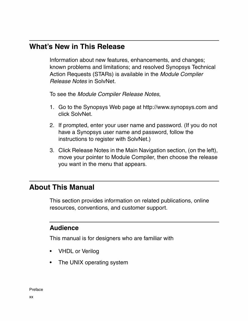
What’s New in This Release
Information about new features, enhancements, and changes; known problems and limitations; and resolved Synopsys Technical Action Requests (STARs) is available in the Module Compiler Release Notes in SolvNet.
To see the Module Compiler Release Notes,
1. Go to the Synopsys Web page at http://www.synopsys.com and click SolvNet.
2. If prompted, enter your user name and password. (If you do not have a Synopsys user name and password, follow the instructions to register with SolvNet.)
3. Click Release Notes in the Main Navigation section, (on the left), move your pointer to Module Compiler, then choose the release you want in the menu that appears.
About This Manual
This section provides information on related publications, online resources, conventions, and customer support.
Audience
This manual is for designers who are familiar with
• VHDL or Verilog
• The UNIX operating system
xx
Preface

• The X Window System
• The basic concepts of synthesis and simulation
Prior knowledge of computer-aided engineering (CAE) tools, ASIC design flow, and digital hardware structures is helpful.
Related Publications
For additional information about Module Compiler, see
• The Module Compiler Reference Manual, which covers in detail keywords, operators, functions, environmental variables, and error messages.
• Synopsys Online Documentation (SOLD), which is included with the software for CD users or is available to download through the Synopsys Electronic Software Transfer (EST) system
• Documentation on the Web, which is available through SolvNet at http://solvnet.synopsys.com
• The Synopsys MediaDocs Shop, from which you can order printed copies of Synopsys documents, at http://mediadocs.synopsys.com
You might also want to refer to the documentation for the following related Synopsys products:
• Physical Compiler
• Design Compiler
• Power Compiler
xxi
Preface

Conventions
The following conventions are used in Synopsys documentation.
Convention Description
Courier Indicates command syntax.
Courier italic Indicates a user-defined value in Synopsys syntax, such as object_name. (A user-defined value that is not Synopsys syntax, such as a user-defined value in a Verilog or VHDL statement, is indicated by regular text font italic.)
Courier bold Indicates user input—text you type verbatim—in Synopsys syntax and examples. (User input that is not Synopsys syntax, such as a user name or password you enter in a GUI, is indicated by regular text font bold.)
[ ] Denotes optional parameters, such as pin1 [pin2 ... pinN]
| Indicates a choice among alternatives, such as low | medium | high(This example indicates that you can enter one of three possible values for an option: low, medium, or high.)
_ Connects terms that are read as a single term by the system, such as set_annotated_delay
Control-c Indicates a keyboard combination, such as holding down the Control key and pressing c.
\ Indicates a continuation of a command line.
/ Indicates levels of directory structure.
Edit > Copy Indicates a path to a menu command, such as opening the Edit menu and choosing Copy.
xxii
Preface

Customer Support
Customer support is available through SolvNet online customer support and through contacting the Synopsys Technical Support Center.
Accessing SolvNet
SolvNet includes an electronic knowledge base of technical articles and answers to frequently asked questions about Synopsys tools. SolvNet also gives you access to a wide range of Synopsys online services including software downloads, documentation on the Web, and “Enter a Call to the Support Center.”
To access SolvNet,
1. Go to the SolvNet Web page at http://solvnet.synopsys.com.
2. If prompted, enter your user name and password. (If you do not have a Synopsys user name and password, follow the instructions to register with SolvNet.)
If you need help using SolvNet, click HELP in the top-right menu bar or in the footer.
xxiii
Preface

Contacting the Synopsys Technical Support Center
If you have problems, questions, or suggestions, you can contact the Synopsys Technical Support Center in the following ways:
• Open a call to your local support center from the Web by going to http://solvnet.synopsys.com (Synopsys user name and password required), then clicking “Enter a Call to the Support Center.”
• Send an e-mail message to your local support center.
- E-mail [email protected] from within North America.
- Find other local support center e-mail addresses at http://www.synopsys.com/support/support_ctr.
• Telephone your local support center.
- Call (800) 245-8005 from within the continental United States.
- Call (650) 584-4200 from Canada.
- Find other local support center telephone numbers at http://www.synopsys.com/support/support_ctr.
xxiv
Preface

1Module Compiler Overview 1
Welcome to the Module Compiler tool, synthesis and optimization software that facilitates high-performance ASIC datapath design.
This chapter includes the following sections:
• What Module Compiler Does
• Benefits of Using Module Compiler
• Application of Module Compiler
• Relationship of Module Compiler to Other Tools
1-1

What Module Compiler Does
With the advent of system on a chip (SoC), datapath content is increasing rapidly. In the past, datapaths were simple and regular. Current datapath designs in video, graphics, and other signal-processing applications are complex and irregular.
Datapath Design
A computational system typically consists of the storage, the control logic, and the computation engine. The computation engine can be built with elements that are as simple as adders and multipliers or as complicated as finite impulse response (FIR) filters or floating-point processors.
A datapath describes elements as well as the interconnections between them. In the context of ASIC technology, datapath refers to the part of an IC that does the computing. In the context of Module Compiler, a datapath is a network of computational and sequential objects, as shown in Figure 1-1.
1-2
Chapter 1: Module Compiler Overview

Figure 1-1 Datapath Is a Network of Computational Objects
Module Compiler Datapath Design
As datapaths have become more irregular and complex, the traditional layout approach to datapath design has broken down. This has forced designers to manually create their datapaths or develop their own in-house utilities. With manual methods and increasing complexity, it is difficult to quickly determine the best architecture and create a suitable datapath circuit.
Module Compiler, a tool for designing datapaths for ASICs, simplifies and automates datapath design. It builds faster and smaller datapaths in less time than traditional datapath design.
One strength of Module Compiler is that it facilitates architectural exploration, helping you quickly find a final architectural candidate. This process is helped through Module Compiler Language, which specifically addresses datapath design. Also, the speed of Module Compiler allows you to synthesize and quickly explore several
*
+
Interconnection
Element
1-3
What Module Compiler Does

architectural choices to determine the best design candidate. Architectural exploration is covered in more detail in Chapter 3, “Key Concepts and Constraints.”
Another strength of Module Compiler is that it is integrated with other Synopsys products, such as the Physical Compiler tool. You can use Module Compiler for fast architectural exploration. Then you can use Physical Compiler to physically optimize your datapath design.
Module Compiler can be run from a graphical user interface (GUI), or you can run it in a Design Compiler or Physical Compiler shell. Module Compiler also integrates with Synopsys Power Compiler to clock-gate a Module Compiler design.
For input, Module Compiler accepts datapath descriptions through the use of Module Compiler Language. Based on your input, Module Compiler synthesizes your datapath into an optimized gate-level circuit that can be integrated with other components of your chip.
Module Compiler synthesizes and optimizes every datapath component in the context of its use. In addition, it provides many advanced techniques that help designers improve productivity. For example, it helps manage latencies and automatically inserts pipelines.
For output, Module Compiler generates a netlist and a Verilog/VHDL behavioral model. You can use the behavioral model in the functional verification of your designs. Module Compiler can generate Verilog, VHDL, EDIF, or Synopsys database format (.db) netlists. You can generate a .db netlist if you have Module Compiler version 1999.05 or later.
1-4
Chapter 1: Module Compiler Overview

Benefits of Using Module Compiler
Module Compiler provides several features for datapath creation. Other tools have some of them, but you need all the features Module Compiler provides for high-performance datapath synthesis and optimization. Specifically,
• Module Compiler facilitates direct and concise descriptions for datapath structures, making it easier to design a datapath and manage its complexity.
• Module Compiler provides quick synthesis output to accurately report performance of different datapath architectures.
• Module Compiler provides integration with several Synopsys tools, such as physical synthesis, physical retiming, and clock-gating datapath designs created in Module Compiler Language. You can easily pass constraints to these tools, using a shared set of Synopsys Design Constraints.
• Module Compiler uses advanced synthesis techniques to achieve datapath performance.
• Module Compiler alleviates the need for special scripts and case tools. It lets you focus more on datapath design and achieve shorter time to market.
• The synthesis speed of Module Compiler, together with your direct synthesis control, facilitates architectural exploration.
• Module Compiler provides automatic pipelining, latency management, signed/unsigned signal handling, and internal rounding. The latter can be used for area-versus-accuracy tradeoff.
1-5
Benefits of Using Module Compiler

• Module Compiler provides built-in functional primitives (shifting, rotation, squaring, saturation, and normalization) that accelerate coding and reduce design time.
• Module Compiler also provides several graphics-related functions, such as gfxBlend, gfxLogicOp, and gfxBit.
• The Module Compiler timing-driven datapath structures, such as bit-optimized Wallace trees, carry-save structures, and hybrid adders, allow Module Compiler to achieve high quality of results (QoR).
• The Module Compiler arithmetic operator merging improves design performance.
• The Module Compiler parameterizable input and technology-independent synthesis facilitate scalability and portability across different vendor processes.
• Module Compiler can synthesize and optimize Module Compiler Language designs in dc_shell and psyn_shell.
Application of Module Compiler
Module Compiler is useful in high-performance, datapath-intensive ASIC designs. These designs are typically found in 3-D, multimedia, high-sample-rate digital signal processing (DSP), and other signal processing applications that involve extensive data conversion and manipulation.
1-6
Chapter 1: Module Compiler Overview
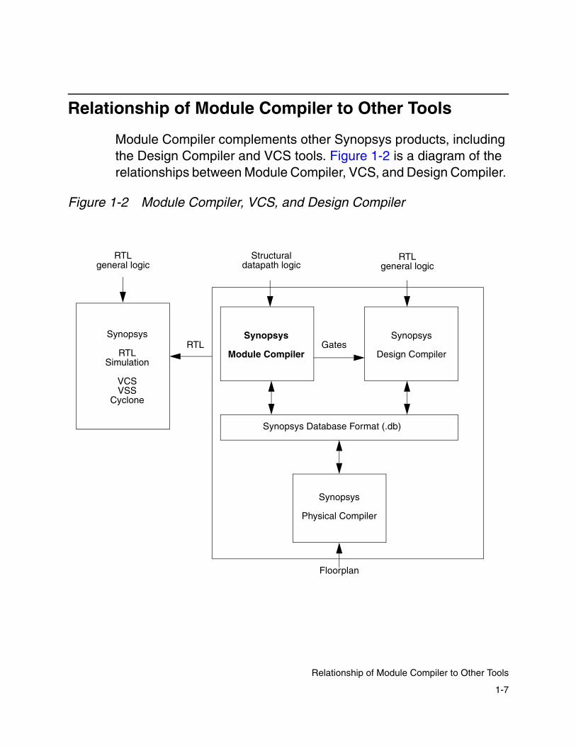
Relationship of Module Compiler to Other Tools
Module Compiler complements other Synopsys products, including the Design Compiler and VCS tools. Figure 1-2 is a diagram of the relationships between Module Compiler, VCS, and Design Compiler.
Figure 1-2 Module Compiler, VCS, and Design Compiler
Synopsys
Module Compiler
Synopsys
Design Compiler
Synopsys Database Format (.db)
RTLgeneral logic
RTLgeneral logic
Synopsys
RTLSimulation
VCSVSS
Cyclone
RTL Gates
Structuraldatapath logic
Synopsys
Physical Compiler
Floorplan
1-7
Relationship of Module Compiler to Other Tools

Module Compiler shares the same database format as Design Compiler and Physical Compiler. It outputs a gate-level netlist that can be used by VCS for simulation or by Design Compiler for further synthesis. Module Compiler synthesizes datapaths by using datapath structural logic and complements Design Compiler and Physical Compiler in the ASIC design flow.
1-8
Chapter 1: Module Compiler Overview

2Installation and Setup 2
This chapter describes how to install Module Compiler and set up the user and group environments. It has the following sections:
• System Administration (Tool Setup)
• First-Run Checklist
• Building Pseudocell Libraries
• Module Compiler Environment Variables
• Using the Module Compiler Properties File
2-1

System Administration (Tool Setup)
This section and the following sections of this chapter are for those who install and maintain Module Compiler. If this does not pertain to you, skip to the next chapter, Chapter 3, “Key Concepts and Constraints.” This section covers platform requirements, licensing, installation, directories, environment variables, and pseudocell generation.
Platform Requirements
The GUI for Module Compiler requires the X Window System. The command-line interface for Module Compiler can be used in any terminal environment. The platform requirements are as follows:
• UNIX workstation
See the Installation Guide for more information.
• Main memory: 128 MB
• Swap space: 250 MB
• Disk space: 250 MB
Licensing
This program requires an MC-Pro-version license key. Module Compiler uses Synopsys Common Licensing (SCL). Synopsys licensing software, installation and configuration—and the documentation describing it—are now separate from Module Compiler as well as from all other Synopsys tools.
2-2
Chapter 2: Installation and Setup
You install, configure, and use a single copy of SCL for all Synopsys tools. Because SCL provides a single common licensing base for all Synopsys tools, it reduces your licensing administration effort. The following resources help you install and configure the SCL software:
• Common Licensing Installation and Administration Guide
This guide provides the following information:
- Detailed SCL installation and configuration instructions, especially useful to the first-time installer
- Conceptual information about SCL and licensing in general
- Multiple examples of license key files, with an explanation of the lines and license keys and the data fields composing them
- Details on migration to SCL from previous Synopsys product-specific licensing systems
- Details on SCL maintenance processes and legacy licensing concerns
- Troubleshooting guidelines
Installation of Synopsys tools and SCL is not order dependent. You can install SCL before or after you install your Synopsys tools, but you cannot use Synopsys tools reliant on SCL until you have installed and configured SCL.
For help with licensing issues, contact your application consultant.
2-3
System Administration (Tool Setup)

Installing
This section covers installation of Module Compiler, which is installed with other synthesis tools such as Design Compiler. For more information, see the Installation Guide. The mcinst command has been made obsolete.
After installation, follow the instructions in “Default Values of Module Compiler Environment Variables” on page 2-10 and “Building Pseudocell Libraries” on page 2-14.
The next section, “Directory Structure,” briefly covers important files in the Module Compiler installation.
Directory Structure
Once installation is successful, you should see a directory structure similar to the diagram in Figure 2-1.
2-4
Chapter 2: Installation and Setup

Figure 2-1 Module Compiler Directory Structure
For information on setting the $SYNOPSYS directory, see the Installation Guide. $MCDIR is automatically installed under $SYNOPSYS. This directory has read-only software directories and directories for local or site-specific customization. Do not modify the read-only portion of the directory tree; it should be preserved in its original state.
adm lib scripts localadm tech
mc
For read-only software release For writable, local, orsite-specific customization
demo
sparcOS5
mc.envsetup.cshsetup.sh
hpux10admin
mc syn
bin bin
mc syn
bin bin
license
auxx packagesdoc
($MCDIR)
$SYNOPSYS
Module Compilerexecutables
(Synopsys synthesis tools root location)
2-5
System Administration (Tool Setup)

The directories under $MCDIR are described below.
• The demo/bin/demo_setup script extracts the Module Compiler demos and places them in a directory you specify and from which you plan to run Module Compiler. Before you run the Module Compiler demos, run the script to extract the demos.
• The localadm directory contains local administration and setup files.
- Use the localadm/setup.csh or localadm/setup.sh script as a source script for initializing your UNIX C or Bourne shell environment, respectively.
- The localadm/mc.env file contains site-specific settings for Module Compiler environment variables.
• The tech directory typically contains technology-specific library files, including the .db libraries. This approach is not required but is convenient. When you are creating pseudocell libraries, Module Compiler writes them into the tech directory.
• The adm, lib, and scripts directories are for Module Compiler usage. You do not need to be concerned about the contents of these directories.
2-6
Chapter 2: Installation and Setup

UNIX Environment Variables
Module Compiler uses a few UNIX environment variables. You can initialize most of these variables by using the localadm/setup.csh or localadm/setup.sh source script.
The environment variables covered in this chapter are for all users of Module Compiler and/or system administrators. If you are an advanced user of Module Compiler, you might want to look at the complete set of environment variables in the Module Compiler Reference Manual.
Table 2-1 identifies and defines the various UNIX environment variables Module Compiler uses. The next section covers technology-specific environment variables it employs.
Table 2-1 UNIX Environment Variables
Type Variable Description
ModuleCompiler
MCDIR The path name of the software installation point. This is the Module Compiler root directory location. Required.
ModuleCompiler
MCLIBDIR The path name of the technology library directory. This directory holds all the technology libraries for Module Compiler, including any pseudocell libraries. Required.
2-7
System Administration (Tool Setup)
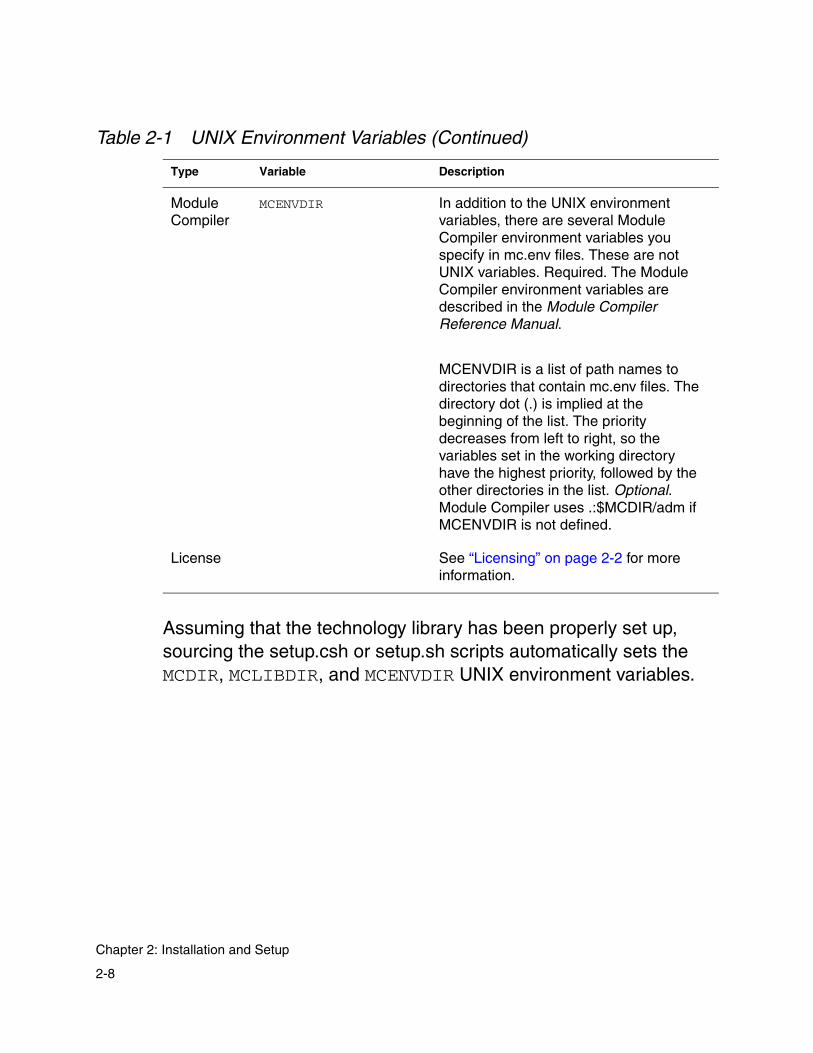
Assuming that the technology library has been properly set up, sourcing the setup.csh or setup.sh scripts automatically sets the MCDIR, MCLIBDIR, and MCENVDIR UNIX environment variables.
ModuleCompiler
MCENVDIR In addition to the UNIX environment variables, there are several Module Compiler environment variables you specify in mc.env files. These are not UNIX variables. Required. The Module Compiler environment variables are described in the Module Compiler Reference Manual.
MCENVDIR is a list of path names to directories that contain mc.env files. The directory dot (.) is implied at the beginning of the list. The priority decreases from left to right, so the variables set in the working directory have the highest priority, followed by the other directories in the list. Optional. Module Compiler uses .:$MCDIR/adm if MCENVDIR is not defined.
License See “Licensing” on page 2-2 for more information.
Table 2-1 UNIX Environment Variables (Continued)
Type Variable Description
2-8
Chapter 2: Installation and Setup
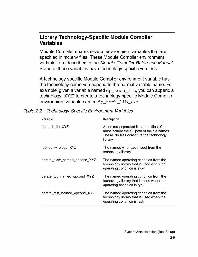
Library Technology-Specific Module Compiler Variables
Module Compiler shares several environment variables that are specified in mc.env files. These Module Compiler environment variables are described in the Module Compiler Reference Manual. Some of these variables have technology-specific versions.
A technology-specific Module Compiler environment variable has the technology name you append to the normal variable name. For example, given a variable named dp_tech_lib, you can append a technology “XYZ” to create a technology-specific Module Compiler environment variable named dp_tech_lib_XYZ.
Table 2-2 Technology-Specific Environment Variables
Variable Description
dp_tech_lib_XYZ A comma-separated list of .db files. You must include the full path of the file names. These .db files constitute the technology library.
dp_dc_wireload_XYZ The named wire load model from the technology library.
derate_slow_named_opcond_XYZ The named operating condition from the technology library that is used when the operating condition is slow.
derate_typ_named_opcond_XYZ The named operating condition from the technology library that is used when the operating condition is typ.
derate_fast_named_opcond_XYZ The named operating condition from the technology library that is used when the operating condition is fast.
2-9
System Administration (Tool Setup)

Table 2-2 identifies and defines the technology-specific Module Compiler environment variables. “XYZ” is used as a placeholder for the technology name. When a variable has technology-independent as well as technology-specific versions, the technology-specific version has the higher precedence.
Default Values of Module Compiler Environment Variables
Module Compiler shares several environment variables that are specified in mc.env files.
Note: In practice, you need to set only a few of these variables, if any. The software installation stores default values for all these variables in the $MCDIR/adm/mc.env file.
The system administrator can override these default values for all users by setting Module Compiler environment variables in the $MCDIR/localadm/mc.env file. This is a convenient way to set preferences for an entire group.
The technology-specific Module Compiler environment variables are the variables the system administrator most commonly needs to manage in the $MCDIR/localadm/mc.env file. To initialize the technology-specific Module Compiler environment variables, follow the steps below.
These instructions assume that the software installation point is /mc2001.08 and that the technology name is XYZ.
2-10
Chapter 2: Installation and Setup

1. Initialize your UNIX environment in the C shell or Bourne shell.
For C shell, use
% source /$SYNOPSYS/mc/localadm/setup.csh
For Bourne shell, use
% . /SYNOPSYS/mc/localadm/setup.sh
2. Change the directory to the localadm directory:
% cd $MCDIR/localadm
3. Execute the following command (where XYZ is the technology):
% mcenv dp_dc_wireload_XYZ my_wire_load
Replace my_wire_load with a named wire load model from the .db libraries:
% mcenv derate_slow_named_opcond_XYZ my_worst
% mcenv derate_typ_named_opcond_XYZ my_typical
% mcenv derate_fast_named_opcond_XYZ my_best
Replace my_worst, my_typical, and my_best with named operating conditions from the .db libraries.
4. Set the dp_tech_lib_XYZ variable according to the location of the library files for the XYZ technology.
Assume that the XYZ technology has two .db library files. If these files are in the $MCDIR/tech directory, execute the following command:
% mcenv dp_tech_lib_XYZ '(MCLIBDIR)/XYZ.db, (MCLIBDIR)/XYZ_wires.db'
2-11
System Administration (Tool Setup)

If the .db files for the XYZ technology are in the /my/dbs/go/here directory, execute the following command:
% mcenv dp_tech_lib_XYZ '/my/dbs/go/here/XYZ.db, /my/dbs/go/here/XYZ_wires.db'
Additional information on library file setup can be found online in SolvNet. See the preface of this manual to find more information on accessing SolvNet.
First-Run Checklist
To get started with Module Compiler, follow the steps in this section. If you are the administrator and need to install and maintain Module Compiler, follow the steps in “System Administration (Tool Setup)” on page 2-2.
The following steps assume that Module Compiler has been properly installed. To run Module Compiler for the first time,
1. Create a new directory.
In this example, the directory is mcproj:
% mkdir mcproj% cd mcproj
2. Initialize your UNIX environment.
In most cases, the administrator will have placed the necessary path information in the setup.csh file, so you need to enter the path to that file.
2-12
Chapter 2: Installation and Setup

For C shell, it is
% source /$SYNOPSYS/mc/localadm/setup.csh
For Bourne shell, it is
% ./$SYNOPSYS/mc/localadm/setup.sh
Sourcing the C shell or Bourne shell scripts sets the variables pointing to the Module Compiler program and the variables pointing to the directories of the technology libraries.
3. Start Module Compiler.
After initializing your UNIX environment, start Module Compiler, using the -tech switch to specify the technology library you want Module Compiler to use. You must specify the technology file containing the smallest inverter in the library first. Module Compiler defines the technology library with the smallest inverter as the main library. If you do not list the main library first, Module Compiler might exit abnormally and fail to build the pseudocell library, or it might build a suboptimal circuit.
% mc -tech XYZ
This command loads the library you specify (XYZ) and runs Module Compiler in GUI mode.
Note:
Module Compiler cannot run without a technology library. You must have a pseudocell library to run Module Compiler with a given technology library. For information on how to generate pseudocells, see “Building Pseudocell Libraries.”
2-13
First-Run Checklist

4. Test Module Compiler.
You will want to test whether your installation of Module Compiler was successful. To test it, click the Do All button. Module Compiler then builds an 8-bit adder, showing its progress in the status window and the log window.
The following sections cover information relevant to subsequent runs of Module Compiler. The final section focuses on Module Compiler system administration issues.
Building Pseudocell Libraries
Module Compiler can construct all cells (excluding basic cells) as pseudocells, if they are not available as native cells in your technology library. This section describes two pseudocell generation flows. Figure 2-2 is an overview of the pseudocell generation flow.
2-14
Chapter 2: Installation and Setup

Figure 2-2 Pseudocell Generation Process
Module Compiler library Technology
Design environment
Wire load model,operating conditions,don’t use cells
Regenerate
NO
YES
Netlist
Global Cache
Local Cache
EDIF and SCDFwire load model, operating conditions,don’t use cells
Pseudocelllibrary
EDIF and SCDFwire load model, operating conditions,don’t use cells
pseudocells?
Synthesizeand
optimize
Module CompilerLanguage
libraryprocessor
Pseudocelllibrary
2-15
Building Pseudocell Libraries
Overview of Pseudocell Generation Flows
Module Compiler datapath synthesis requires that some generic functions be implemented as cells in the synthesis library. However, most of the technology libraries do not have functionally equivalent cells for the generic functions Module Compiler requires.
To address this problem, Module Compiler provides a pseudocell generation capability to build required generic functions as pseudocells. These cells are used during synthesis and are flattened in the final netlist Module Compiler generates.
There are two new flows for pseudocell generation:
• The automatic pseudocell generation flow, which occurs automatically during runtime (building the local cache)
- Module Compiler creates pseudocells automatically during runtime for specified wire load models and operating conditions. You can specify these conditions in the mc.env file.
- Module Compiler uses the local cache to store the pseudocells it generates during runtime.
• The makeMcLibCache flow (Figure 2-3 on page 2-19), in which you use makeMcLibCache to prebuild pseudocells (building the global cache)
Before running Module Compiler, you can elect to prebuild pseudocells and store them in a global cache.
- You prebuild pseudocells for a set of wire load models and operating conditions.
2-16
Chapter 2: Installation and Setup

- The global cache you create with makeMcLibCache can be shared between designers. Therefore, it is recommended that pseudocell libraries created this way should not be design specific.
- The global cache is read only. In other words, Module Compiler only reads from a global cache and never writes to it.
When using the flows, consider the following:
• Module Compiler builds pseudocells automatically only for generic cells that are not present in your technology library.
• Module Compiler gives precedence to a local cache over a global cache.
For example, if a particular pseudocell exists in both the global and the local cache, Module Compiler reads it from the local cache. Module Compiler reads it from the global cache only if it is not present in the local cache.
Caution! Do not close the Module Compiler Library Options window during automatic pseudocell generation. Doing so results in an error message.
2-17
Building Pseudocell Libraries

Automatic Pseudocell Generation
Module Compiler automatically generates pseudocells for generic functions not available in your technology library.
The automated pseudocell generation flow has these characteristics:
• The automated method provides better results, because it builds pseudocells only for synthesis cells that have no corresponding technology cells.
• The automated flow is easier to use, because you do not have to take the extra step of manually creating pseudocells.
• Each time a wire load model, operating condition, or set of don’t use cells changes, pseudocells are automatically generated with the new conditions.
Note: Automatic pseudocell generation is enabled with the dp_buildpseudolib variable. By default, this variable is set to +. Synopsys recommends leaving dp_buildpseudolib at its default setting.
Conditions for Automatic Rebuilding of Pseudocells
Module Compiler rebuilds pseudocells automatically during runtime and stores them in a local cache:
• Module Compiler rebuilds pseudocells if the pseudocell library available in a global cache or a local cache contains don’t use cells. Specifically, you apply the dont_use attribute to certain cells after pseudocells have been built. Then Module Compiler
2-18
Chapter 2: Installation and Setup
automatically rebuilds the local cache pseudocell library. The new local cache pseudocell library does not contain any don’t use cells. No changes are made in the global cache library.
• If the wire load or operating conditions change, Module Compiler automatically rebuilds local cache pseudocells, based on the new wire load models and operating conditions. No changes are made in the global cache library.
• If the technology library changes and is older or newer than the pseudocell library, Module Compiler automatically rebuilds the local cache pseudocell library. No changes are made in the global cache library.
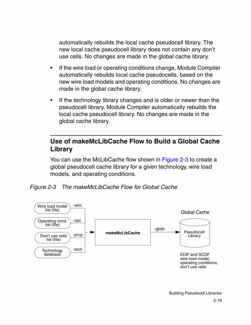
Use of makeMcLibCache Flow to Build a Global Cache Library
You can use the McLibCache flow shown in Figure 2-3 to create a global pseudocell cache library for a given technology, wire load models, and operating conditions.
Figure 2-3 The makeMcLibCache Flow for Global Cache
makeMcLibCache
Wire load modellist (file)
Operating cond.list (file)
Technology
Don’t use cellslist (file)
-tech
-prop
-opc
-wlm
-gbdirPseudocell
Library
Global Cache
EDIF and SCDFwire load model, operating conditions,don’t use cells
database
2-19
Building Pseudocell Libraries

You can choose to use this flow if you know you need a certain set of wire load models and operating conditions for running Module Compiler. Therefore, use this flow to prebuild a pseudocell library for given sets of wire load models and operating conditions.
Use the makeMcLibCache command to prebuild the global cache. For example,
makeMcLibCache -tech technology_name -wlm wire_load_model_file -opc operating_condition_file [-prop dont_use_cell_file][-gbdir global_cache_dir]
The makeMcLibCache options, as shown in the previous example, are
• -tech
This option specifies the technology library.
• -wlm
This option specifies the file containing the list of wire load models. A wire load model file is required.
Specify one wire load model per line, as shown in Figure 2-4. Do not use commas or semicolons.
Figure 2-4 Wire Load Model File Examplesynlinear 0synlinear 1b1x1b2x2..
2-20
Chapter 2: Installation and Setup

• -opc
This option specifies the file containing the list of operating conditions. An operating condition file is required.
To specify the operating conditions in a file, you must specify one per line, as shown in Figure 2-5. Do not use commas or semicolons.
Figure 2-5 Operating Condition File Example
• -prop
This option specifies the file containing the list of don’t use cells for the global cache library, which is shared by a group of designers. Using a don’t use file with makeMcLibCache is optional.
To specify a file containing a list of don’t use cells, specify one per line, as shown in Figure 2-6. Do not use commas or semicolons.
Figure 2-6 Properties File for makeMcLibCache
synlibcondnomwaccomwcmil..
dont_use mcgen_mule1adont_use mcgen_nand4edont_use jims_buf1adont_use my_nor2b..
2-21
Building Pseudocell Libraries
Note:
Because the pseudocell library built in the global area can be shared with other designers, be careful when you apply dont_use on cells in the global cache.
• -gbdir
This option specifies the directory of the global cache. Using it is optional. By default, -gbdir points to ./pcellgloballib.
The following example creates a global cache. Because the technology library name is 400e, the wire load model file name is 400e.wlm, the operating condition file name is 400e.opc, and the desired global cache directory name is /remote/pcells_g/global_lib.
% makeMcLibCache -tech 400e -wlm 400e.wlm -opc 400e.opc -gbdir /remote/pcells_g/global_lib
To use this global cache, you enter
% mcenv dp_pseudotechglobaldir /remote/pcells_g/global_lib
in either the working design directory or, if the global cache is shared by others, the $MCDIR/localadm/ directory.
Specification of Cache Directories
In the automatic pseudocell generation flow, Module Compiler builds pseudocells automatically and stores them during runtime in a local cache. Alternatively, in the makeMcLibCache flow (Figure 2-3), Module Compiler prebuilds the pseudocell library for your specified technology library, wire load model, and operating condition into the global cache.
2-22
Chapter 2: Installation and Setup
Module Compiler has two environment variables you can set before using these two pseudocell generation flows:
• dp_pseudotechlocaldir
Set this variable when you are using the automatic pseudocell generation flow (building pseudocells during runtime). It specifies the directory of the local cache directory. The default directory is ./pcelllocallib.
To change a local cache directory, enter the following at the UNIX prompt, where local_cache_dir is the name of the local directory you want to set.
% mcenv dp_pseudotechlocaldir local_cache_dir
• dp_pseudotechglobaldir
Set this variable to specify the directory of the global cache directory. The default directory is ./pcellgloballib.
To change the global cache directory, enter the following at the UNIX prompt, where gbl_cache_dir is the global directory you want to set.
% mcenv dp_pseudotechglobaldir gbl_cache_dir
2-23
Building Pseudocell Libraries

Rebuilding Local and Global Cache Directories
Rebuild your local and global pseudocell libraries for each new version of Module Compiler. You run the risk that your design might not work if you fail to adopt this practice.
If you have not specified a local cache directory, delete the default local cache directory, ./pcelllocallib., to rebuild the local cache. If you specified a local cache directory name, delete that directory instead. The local cache is created automatically when you run Module Compiler again.
To delete and rebuild the global cache directory, delete the directory specified by the makeMcLibCache -gbdir option when building the global cache. After deleting this directory, run makeMcLibCache again to create a new global cache directory, which will not be automatically regenerated.
Module Compiler Environment Variables
When you run Module Compiler for the first time in a directory, Module Compiler writes a default mc.env file in that directory. This file stores the Module Compiler environment variable settings.
When you run Module Compiler again, it uses the default environment values stored in the mc.env file. If you do not want to start up in the previous configuration, you can use the mcenv utility to change the setting in the mc.env file. Alternatively, you can use a text editor such as vi or emacs to edit the mc.env file.
2-24
Chapter 2: Installation and Setup
You can change the default value of an environment variable by using the GUI and/or the mcenv utility. The mcenv utility stores your new environment variable settings in the mc.env file. For information on the mcenv utility, see “Using the mcenv Utility” on page 2-26.
When you run Module Compiler, it writes out a new mc.env file. If you have not made any changes to the Module Compiler environment variables, this file will not change. As a rule, for each directory, Module Compiler writes only one mc.env file.
If you want to run Module Compiler with a different mc.env file, you need to run Module Compiler in a different directory. Then, using the GUI and/or the mcenv utility, you can make your changes to the mc.env file in that directory. When you run Module Compiler again in that directory, it uses the settings from the mc.env file in that directory.
In addition to the mc.env file, Module Compiler also supports sessions, which are a collection of all GUI settings for a run, including synthesis, optimization, and report settings. You must explicitly save and load sessions. To do so, choose Sessions from the File menu in the Module Compiler GUI.
Module Compiler stores the settings from your GUI run in a session file and names the session file with a .dps extension. Module Compiler does not require you to use sessions. If you do not use them, it does not create a .dps file in the directory in which it is running.
When running Module Compiler, you can save and load one or more sessions. For each directory, Module Compiler writes one or more .dps files, which means that in a directory, you can save multiple sessions to load and reuse in Module Compiler.
2-25
Module Compiler Environment Variables

Note: Do not change any of the settings in mc.env or in the session file when using the Module Compiler GUI. Making environment variable changes when the GUI is running can cause Module Compiler to operate incorrectly.
Using the mcenv Utility
You can use the mcenv utility to set and query Module Compiler environment variables. When you set a Module Compiler environment variable, the mcenv utility stores the value in the mc.env file.
When you set an environment variable, using the mcenv utility, it is the same as if you used a text editor to add or change the mc.env file.
Note: Be careful to correctly spell the name of the Module Compiler environment variable when using the mcenv utility. The utility does not check to see if the variable name you are entering is a valid Module Compiler environment variable. The mcenv utility gives no indication when the variable or setting is incorrect but adds or changes the mc.env file exactly as you have entered it.
When you query the value of an environment variable, the mcenv utility first checks in the ./mc.env file for the Module Compiler variable, ensuring that the working directory has the highest priority.
Next, it checks directories in the MCENVDIR list, from left to right, until it locates the environment variable. This is the same mechanism Module Compiler uses when it checks for variable values.
2-26
Chapter 2: Installation and Setup

To set a Module Compiler environment variable
• Start the mcenv utility by entering the mcenv command.
• Specify the environment variable name and its new value, as illustrated in the following example, which sets the value of the dp_opcond environment variable to slow:
% mcenv dp_opcond slow
To query the value of most Module Compiler environment variables, you specify the environment variable name, as shown in the following example:
% mcenv dp_opcond
This returns the value of the dp_opcond environment variable.
To query the value of a Module Compiler environment variable that has a technology-specific version, you use the -tech switch:
% mcenv -tech dp_tech_lib
This returns the value of the dp_tech_lib variable with the highest priority. Because all technology-specific variables have higher priority than technology-independent variables, the mcenv command returns the technology-specific version for the current technology, if one exists.
2-27
Module Compiler Environment Variables

Using the Module Compiler Properties File
Use the Module Compiler properties file to add the dont_use property to cells that do not already have the property set to dont_use in the .db library file. The dont_use property has the same meaning in Module Compiler as the dont_use property used with .db libraries.
You set the name of the properties file by using the dp_prop_fname Module Compiler environment variable. Its default value is
Module_Compiler_Library_DIR/techname.prop
where techname is the symbolic name of your technology. The dp_prop_fname variable should be specified in the $MCDIR/localadm/mc.env file to have the full scope of the dont_use property on a library-wide basis.
As shown in Figure 2-7, the properties file format does not allow comments or wildcards. Each row of the properties file consists of dont_use followed by a cell name, as shown in the following simple four-line example of a properties file:
Figure 2-7 Properties File Format
dont_use YFD1dont_use YFD1Sdont_use BDCL3dont_use JKS1
2-28
Chapter 2: Installation and Setup

The library report file has information you might use in creating the Module Compiler properties file. Look especially at the “Equivalent Cells” section of the library report because this section, which appears at the very end of the file, lists all cells having the same Boolean function—that is, equivalent cells.
The library report file is written into your working directory when you run Module Compiler. To find this file, look for a file with a .rep suffix. For example, if your symbolic technology name is symbtech10, the name of your library report file is symbtech10.rep.
2-29
Using the Module Compiler Properties File

2-30
Chapter 2: Installation and Setup

3Key Concepts and Constraints 3
In this chapter, you learn about fundamental concepts and constraints affecting your use of Module Compiler. It contains the following sections:
• Starting Module Compiler
• Command-Line Interface
• Flow for Building Modules
• Module Compiler Design Flow
• Building Datapaths
• Synthesis and Optimization
• Hierarchy Through Functions
• Network Objects
3-1

• Network Attributes
• Designer Control
3-2
Chapter 3: Key Concepts and Constraints

Starting Module Compiler
For instructions on installing and starting Module Compiler, see “First-Run Checklist” in Chapter 2. By default, Module Compiler runs in GUI mode. Chapter 4, “Graphical User Interface,” describes this GUI in detail. You can also run Module Compiler in batch mode.
When you start Module Compiler, the main window appears, as shown in Figure 3-1. You can use the GUI to specify an input file and enter parameters. The File menu provides a browser to help you locate input files in the UNIX directory structure. You can manually set the parameter lists for synthesis and optimization, or you can have Module Compiler extract them from the input file.
Figure 3-1 The Module Compiler Main Window
3-3
Starting Module Compiler

Command-Line Interface
Module Compiler supports a command-line interface, which allows you to automate with scripting. Each time you start Module Compiler, it executes the command options you provide, in batch mode, and then exits. In contrast, the GUI provides an easy and interactive point-and-click approach to datapath design and has become the preferred mode.
You can set most of the command-line options through the GUI. However, when you start Module Compiler, you must specify certain options (such as -gm + or -gm -, indicating whether you want graphics or interactive mode) on the command line.
To see what options are available, enter mc -h in an open window. Example 3-1 shows the output that lists the available command-line options.
Example 3-1 mc -h Output of Command-Line OptionsOptions for program `mc':
-b <HDL Behavioral Model Output Flag(- for no output, + to output)> -cw <Continue on Warnings (- to stop, + to continue)> -db <DB Netlist Output Flag (- for no output, + to output)> -dc_run <Run DC (- to not run, + to run)>-debugsim <Use Long Instance Names (- for short, + for long)> -eg <equalize delays globally (- for local, + for global)> -ep <num of global passes which equalize group delay>-fp <flatten pseudo cells (- to leave, + to flatten)>-gi <max global opt iterations>-gm <graphics mode (- for text, + for graphical)>-i <input file name>-il <default input max loads (0.1 std load)>-l <log file name (- for stdout)>-lang <HDL (Verilog/VHDL/Verilog_VHDL)>-layout <Generate Layout Information (- for off, + for on)> -li <max local opt iterations>-ln <use group names (- for no, + for yes)>
3-4
Chapter 3: Key Concepts and Constraints

-logmode <log file open mode ('a' or 'w')>-m <verbose mode: debug, syntax, normal >-me <max number of errors to print>-o <optimization type (speed ,size, power, delay in ps)>-oc <operating condition>-ol <default output loading (0.1 std load)>-opt <logic optimization level (0 for none, -1 for all)>-p <pipeline flag (- for off, + for on)>-par <input parameters (- for none)>-pf <parse input before loading libs>-pi <iteration control file name (- for none)>-pp <preprocessor (dd,dpp,-)>-ps <pipelining margin (in ps)>-r <timing/area report flag (- for none, + to generate)>-rt <build regular trees (- for off, + for on)>-sm <support scan test mode (- for off, + for on)>-sd <leave scan reg in final netlist (- for off, + for on)>-sdc <Synopsys Design Constraints file (- for none)>-strict <Strict parsing (+ for on, - for off)>-t <table file name>-tech <technology name>-tl <top level mode (- for off, + for on)>-to <table output flag (- for none)>-v <HDL logic model output flag (- for no output, + to output)>-cg <Clock gating output flag (- to disable, + to enable)>
Table 3-1 lists the command-line options available in Module Compiler, along with their equivalent environment variable and a brief description. Unless otherwise stated, the +|– value indicates + (plus sign) to enable and – (minus sign) to disable.
Table 3-1 Module Compiler Command-Line Options
Command-line option
Equivalentenvironment variable
Default Description
-b dp_bver_out + Behavioral model output flag (+|−)
-cg dp_clockgating − Sets the clock-gating capability (+|−)
-cw dp_contwarn + Continue on warning flag (+|−)
-db dp_db_out − Controls whether a .db netlist is generated (+|−)
3-5
Command-Line Interface

-dc_run dp_dc_run − Runs Design Compiler (+|−)
-debugsim dp_debugsim − Enables and disables the use of debugging names in the netlist models (+|−)
-eg dp_equalglob + Specifies global equalization (+|−)
-ep dp_equalpass 1 Sets number of equalization iterations (1, 2, ...)
-fp dp_pseudo_flat + Flattens pseudocells (+|−)
-gi dp_maxgiter 2 Number of global optimization iterations (1, 2, ...)
-gm dp_graphmode + Enables graphics mode (+|−)
-i dp_in dp_libpath/test.mcl
Input file name; in GUI mode, the input file name is taken from the session
-il dp_inload 400 Default maximum input load, in 0.1 standard load (any positive real number)
-l dp_log − Log file name (− for standard output)
-lang dp_lang_out verilog Specifies the simulation language format (Verilog, VHDL, Verilog_VHDL)
-layout dp_layout_out + Generates relative placement layout output (+|−)
-li dp_maxliter 4 Maximum number of local optimization iterations (1, 2, ...)
Table 3-1 Module Compiler Command-Line Options (Continued)
Command-line option
Equivalentenvironment variable
Default Description
3-6
Chapter 3: Key Concepts and Constraints
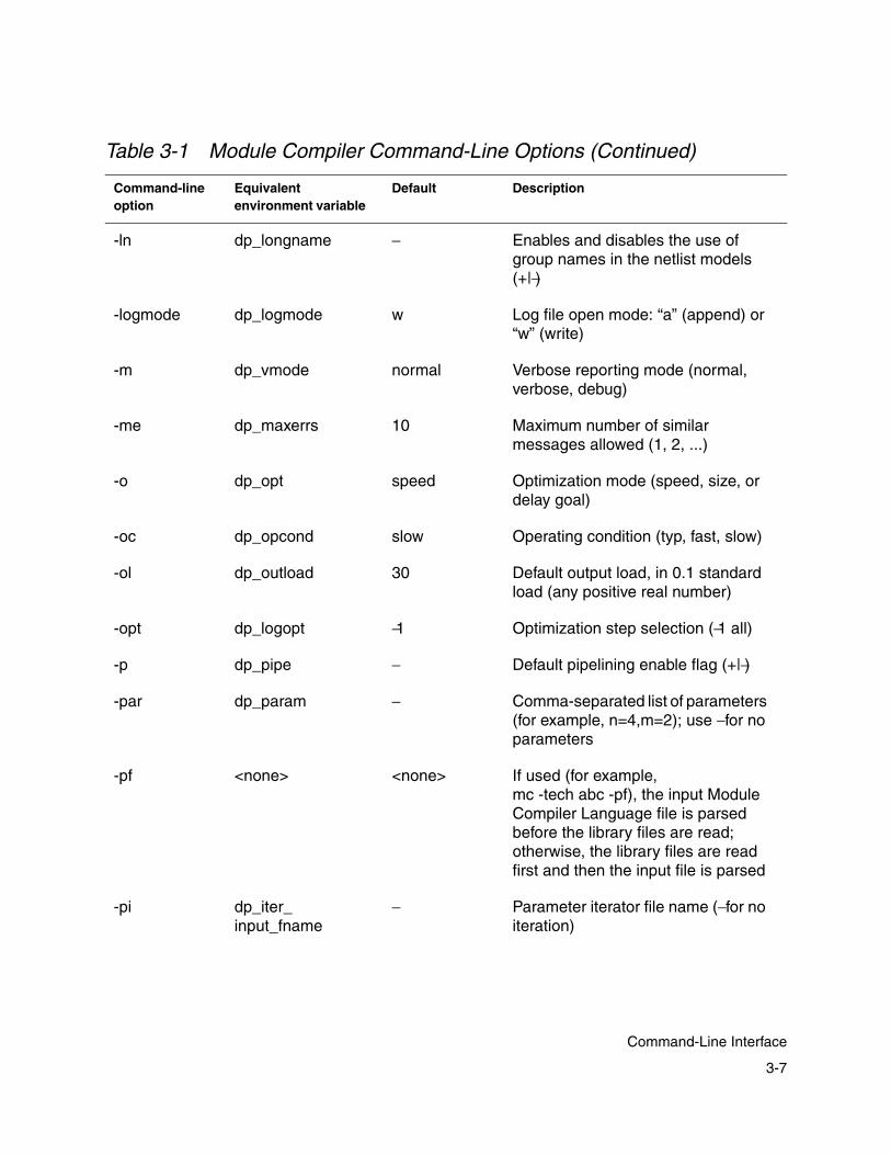
-ln dp_longname − Enables and disables the use of group names in the netlist models (+|−)
-logmode dp_logmode w Log file open mode: “a” (append) or “w” (write)
-m dp_vmode normal Verbose reporting mode (normal, verbose, debug)
-me dp_maxerrs 10 Maximum number of similar messages allowed (1, 2, ...)
-o dp_opt speed Optimization mode (speed, size, or delay goal)
-oc dp_opcond slow Operating condition (typ, fast, slow)
-ol dp_outload 30 Default output load, in 0.1 standard load (any positive real number)
-opt dp_logopt −1 Optimization step selection (−1 all)
-p dp_pipe − Default pipelining enable flag (+|−)
-par dp_param − Comma-separated list of parameters (for example, n=4,m=2); use − for no parameters
-pf <none> <none> If used (for example,mc -tech abc -pf), the input Module Compiler Language file is parsed before the library files are read; otherwise, the library files are read first and then the input file is parsed
-pi dp_iter_input_fname
− Parameter iterator file name (− for no iteration)
Table 3-1 Module Compiler Command-Line Options (Continued)
Command-line option
Equivalentenvironment variable
Default Description
3-7
Command-Line Interface

-pp dp_preprocessor mcp Selects parser (mcp for new parser, dd for old parser)
-ps dp_pipemargin 0 Default pipeline margin, in ps(0, 1, ...)
-r dp_rep_out + Report output file flag (+|−)
-rt dp_regtrees − Builds regular trees (+|−)
-sd <none> <none> Scan debug: Scan registers are left in the output netlist; otherwise, they are replaced by nonscan cells
-sdc dp_sdc_in − Passes an SDC constraints file as an argument to Module Compiler (− for no constraints file)
-sm dp_scanmode − Scan test mode flag (+|−)
-strict dp_strict + Strict language usage flag; when enabled, use of obsolete constants, functions, or hidden conversions generates warnings (+|−)
-t dp_tbl_name table Name of the table file
-tech dp_tech <none> Specifies the technology library that Module Compiler uses
-tl dp_toplevel − Chip top-level flag (+|−)
-to dp_tbl_out + Generates the table file (+|−)
-v dp_ver_out + Verilog structural model file flag (+|−)
Table 3-1 Module Compiler Command-Line Options (Continued)
Command-line option
Equivalentenvironment variable
Default Description
3-8
Chapter 3: Key Concepts and Constraints

Flow for Building Modules
Using Module Compiler begins with the design input file and ends with the Module Compiler outputs. The overall process of running Module Compiler consists of the following steps.
1. Start Module Compiler. If you want to use a technology other than the one you used when you last started Module Compiler in the current directory, specify the technology with the -tech switch at the command line, For example,
% mc -tech my_tech_lib
2. Select or edit input files, operating conditions, and parameters, if needed.
3. Set Synthesis options, if needed. Synthesize.
4. Set Optimization options, if needed. Optimize.
5. Set Reports options, if needed. Generate and view reports.
6. Modify the Module Compiler input file or files, if needed.
7. Iterate (go back to step 4).
The Module Compiler development process has three overall stages: synthesis, optimization, and analysis. Your development process can be sequential, but often you will work interactively between these three stages. Each stage is described below.
Depending on the objective, you might be able to skip some of the steps in an iteration. For example, you can skip optimization if the objective is behavioral simulation. If there has been no change since the last iteration, you do not need to set the options again.
3-9
Flow for Building Modules

• The synthesis stage
This stage consists of specifying the input file, Module Compiler libraries, and design processing parameters. Module Compiler parses the input file and the libraries.
If parsing is successful, Module Compiler synthesizes the design and creates a technology-mapped implementation of the design. If the parsing fails or if the synthesis results are not acceptable, you can edit the input file and synthesize again.
• The optimization stage
This stage consists of improving synthesis results. If the results of the optimization stage are not acceptable, you can edit the input files and/or specify different options. You must then repeat the synthesis and optimization steps.
• The results analysis stage
This is the last stage. During optimization, Module Compiler provides statistical data about the results in several reports.
During results analysis, you decide on the design data you want to generate and view. After evaluating the design data, you can return to the optimization stage to change optimization parameters or you can proceed and integrate the results into your design environment.
3-10
Chapter 3: Key Concepts and Constraints

Module Compiler Design Flow
Module Compiler builds high-performance datapaths. It supports a GUI as well as a command-line interface. The diagram in Figure 3-2 shows where Module Compiler fits in the standard ASIC design flow.
Figure 3-2 Design Flow and Module Compiler
The input to Module Compiler consists of some design constraints and a high-level description of the datapath written in Module Compiler Language. You describe the design constraints through the GUI or embed them in the input description, from Module Compiler Language.
Module Compiler Language was written for datapath synthesis and optimization. It provides performance, efficiency, and high-quality results compared to alternative tools that use older languages.
netlist creation
Schematics
Design Compiler
Module Compiler
pre-layout simulation
layout
VCS, VSS, Verilog-XL, etc.
Design Flow Tools Used
Place and Route
VCS, VSS, Verilog-XL, etc.
post-layout simulation
3-11
Module Compiler Design Flow

Although Module Compiler Language is a new language, it is easy to learn, because it has the look and feel of the Verilog HDL.
If there is a conflict between the GUI and Module Compiler Language, the Module Compiler Language design constraints override the GUI inputs. The output of Module Compiler is the synthesized and optimized circuit represented in various model views and report files.
The interaction of Module Compiler with other CAE/CAD tools in a typical design flow is shown in Figure 3-3.
Figure 3-3 Process Flow in Module Compiler
Module Compiler Language
Module Compiler
Action
Data
Exploration Loop
Verilog/VHDL netlist
Simulation
Debugging Loop
Module Compilerreports
input file(s)
Design requirements
Architectural changes
Verilog or VHDL behavioral
model
3-12
Chapter 3: Key Concepts and Constraints
The Module Compiler process flow is typical of synthesis tools’ process flow. Using a text editor, you start by writing the input description in an HDL such as Module Compiler Language. Module Compiler Language is described in detail in Chapter 5, “Module Compiler Language Guide,” and Chapter 6, “Module Compiler Language Usage.”
Module Compiler is an excellent tool for architectural exploration. You can run many iterations to achieve the best tradeoff of circuit performance and area. Performance considerations are discussed in “Optimizing Performance and Area” on page 6-85 and “Optimization” on page 8-63.
In the exploration phase, you run Module Compiler and analyze its output reports. You then modify the input files to optimize the macroarchitecture. For more information on output, see “Module Compiler Output Files” on page 8-2.
In the debugging phase, you run Verilog or VHDL behavioral simulation to ensure that the design description is correct. For example, in this phase, you can check to see whether the latency introduced by automatic pipelining is acceptable. For more information on simulation, see “Verilog or VHDL Simulation” on page 8-34. Additional information on debugging can be found in “Debugging” on page 8-53.
When the costs (area and performance) and the Verilog or VHDL RTL model are acceptable, you can generate an optimized netlist for your design. This netlist can be a Verilog, VHDL, EDIF, or .db netlist.
You can generate a .db netlist if you are using Module Compiler version 1999.05 or later.
3-13
Module Compiler Design Flow

Note that the gate-level netlist (.db) created by Module Compiler does not contain design constraints, such as timing constraints. If you want to include such constraints in the .db, you can read the Module Compiler-created .db into Design Compiler or Physical Compiler, apply your constraints, and write out the .db file again. This new .db file then contains the appropriate constraint information.
Building Datapaths
In the context of Module Compiler, a datapath is a network of computational and sequential objects. The following sections provide an overview of the objects (and attributes) in this network as well as the basic concepts involved in constructing and evaluating a network.
Module Compiler uses the network objects in the input description you supply. After synthesis and optimization, it provides a summary of the network attributes, helping you evaluate the original description. The network attributes include timing and area.
By controlling the synthesis and optimization processes, you can affect these attributes. You do this by making architecture selections or by setting constraints and optimization goals. Module Compiler also provides some control over testing, through scan test methodologies implemented by third-party tools.
3-14
Chapter 3: Key Concepts and Constraints
Synthesis and Optimization
The two primary steps in generating a circuit are synthesis and optimization. Synthesis is the process in which a high-level input description in the Module Compiler Language format is converted to a gate-level network. Optimization following synthesis modifies the gate-level network to improve area and delay.
Hierarchy Through Functions
Designers use hierarchy to break a large task into smaller ones. Most IC designs adopt a hierarchical methodology, because the general-purpose logic synthesizers tend to be slower at processing large blocks of logic.
There are difficulties in using hierarchical approaches. Traditional hierarchy is a tradeoff between time and efficiency of implementation.
With extensive hierarchy, timing problems typically occur at the boundaries of the hierarchy and are often not found until late in the design process. Reuse provides efficiency of implementation, but other difficulties occur when you try to reuse a module with the hierarchical structures.
For example, using the hierarchical approach, you optimize a module only once, not for each of its instances. In addition, as your technologies and cell libraries improve, your fixed design becomes obsolete.
3-15
Synthesis and Optimization

In light of these problems, Module Compiler provides a different set of constraints that makes the use of extensive hierarchical structure feasible. For most circuits, the traditional form of hierarchy degrades the quality of the output without reducing the design time.
Module Compiler addresses this issue by providing a hierarchy in the “idea space,” which does not become hierarchy in the final design. The input to Module Compiler is hierarchical, whereas the output is flat.
With Module Compiler, you can break your ideas into hierarchical segments. You can implement these ideas in the form of functions in your design description. Module Compiler flattens these segments before synthesis and optimization. Module Compiler then synthesizes and optimizes each instance of the design for its particular environment.
For example, you might discover that you need to use a counter many times in your design. Instead of creating a fixed counter cell in the design and instantiating it many times, you can create a parameterized function where each counter is synthesized and optimized independently of the other instances of the counter.
This Module Compiler method has an added benefit. The counters in more-critical sections of the design are optimized differently than those in less-critical sections, which increases the performance while keeping the area small.
3-16
Chapter 3: Key Concepts and Constraints

Network Objects
To create a network (design) description for synthesis, you must first understand the objects used in the description. These objects are designs, functions, operands, instances, and timing groups.
At the root of the hierarchical tree of objects is the design that corresponds to a single synthesized module. Module Compiler always creates a design with a single level of hierarchy.
The design comprises timing groups, which are maintained by Module Compiler. Timing groups are user-defined groups that have the same delay goal or desired delay. Each specified delay goal has one timing group.
A group consists of one or more selected operands. All operands within a group must have the same delay goal. Module Compiler maintains statistics such as area and critical path for each group and provides this information in the design report.
You can define as many groups as necessary to understand how the area, latency, and delay costs of the design are distributed. The misc group is predefined by Module Compiler at the beginning of every design and contains all the operands not included in a user-defined group.
Operands represent the signals in a network. A signal can have a signed or unsigned format and can be either a constant or a variable. For example, CLK is a predefined operand for the global clock.
Functions and operators connect operands. A function or operator specifies the method of computing the output operands from the input operands.
3-17
Network Objects
Module Compiler provides an extensive set of basic functions and operators associated with datapath synthesis. These include arithmetic addition, subtraction, and multiplication and logical AND, OR, and XOR. Also included are saturation, shifting, rotation, normalization, comparison, multiplexing, and so on.
Module Compiler provides a function for each cell in the technology library. You can instantiate these cells by calling the function. Similarly, you can include other cells or netlists in the design by creating a Module Compiler Language function.
Network Attributes
The network attributes provide information regarding the costs of implementing a circuit. Module Compiler considers timing to be the primary cost. That is, if the delay goal is not met, any amount of area can be spent to achieve the delay goal.
Note: You can give area a higher priority than timing. For more detail, see “Optimization” on page 3-29.
Area is a secondary cost; Module Compiler minimizes for area only after it meets the delay goal.
You control the synthesis and optimization processes by making architecture selections or specifying constraints. You accomplish this control through the use of Module Compiler directives. For more information about directives, see the Module Compiler Reference Manual.
3-18
Chapter 3: Key Concepts and Constraints
Timing
Achieving high performance requires careful attention to timing during synthesis and optimization. Timing has two primary components: continuous time delay and discrete time delay (latency).
In nonsequential circuits, only the continuous time component is meaningful. In sequential circuits, and especially in DSP-oriented circuits, the latency component is a major design issue.
For sequential circuits, Module Compiler supports one or more global single-phase rising-edge clocks, available throughout the Module Compiler Language hierarchy. For sequential or nonsequential circuits, Module Compiler provides several mechanisms for optimizing, reducing, and managing these delays.
Although clocks are independent, Module Compiler uses a simple timing model in which all clocks have no skew relative to each other. In uncommon cases that require multiple clocks, you must ensure that the design is not sensitive to clock skews. Module Compiler does not buffer clocks but assumes that you are solving the actual clock distribution during place and route.
Module Compiler uses standard Synopsys wire load models for pre-layout timing calculations during synthesis and optimization. Because the exact wire lengths are unknown until place and route is completed, Module Compiler uses estimates defined by the Synopsys wire load model.
3-19
Network Attributes
Continuous Time Delay
Module Compiler provides standard state-independent support for continuous time delays. It maintains separate rise and fall delays for each net and uses the uniqueness of the timing arcs to generate the most-accurate delays possible.
Module Compiler synthesizes every operand before referencing it as an input having a timing arc to one or more of the outputs. This method ensures that Module Compiler knows the delays of all inputs to a function when synthesizing a function.
Module Compiler sorts the network automatically to guarantee that it synthesizes operands in the correct order, regardless of the ordering of operands specified in the input description. If the network cannot be sorted when Module Compiler encounters a continuous time loop, Module Compiler issues an error message.
One of the primary goals of the synthesizer is to minimize delay, thus maximizing performance. Designers use Wallace trees extensively to meet this goal, because the final circuit takes into account both the cells being used in the synthesis and the arrival times of all inputs.
Wallace trees provide high-performance circuits for multiplication, and you can also use them for adders and logic, such as AND, OR, and XOR. For more information on Wallace trees, see “Logical, Reduction, Shift, and MUX Operators” on page 6-30. Module Compiler takes advantage of Wallace trees to create high- performance datapath circuits.
Module Compiler provides two other adder architectures that adapt to input arrival times as well as output delay goals to minimize the area for a given performance level. Module Compiler takes
3-20
Chapter 3: Key Concepts and Constraints

advantage of other techniques, such as optimizing the selected inputs of multilevel multiplexer structures, to accommodate skewed arrival times.
The primary goal of Module Compiler is to minimize delay. This behavior is sometimes undesirable when delay matching is employed (for example, to meet a hold time) or when the delay of the circuit has been purposely increased. Module Compiler provides directives for overriding the default behavior and turning logic optimization off for all or part of the design.
Latency and Registers
Module Compiler provides extensive support for controlling and optimizing latency. You can employ state as well as pipeline registers. You can also choose between automatic pipelining (pipeline = on) and manual pipelining (pipeline = off); see “Automatic Pipelining” on page 3-27.”
Complex designs require state and pipeline registers. State registers provide delay that is required by the algorithm being implemented; for example, the accumulator of a multiplier accumulator (MAC) is required for the operation of the MAC. In contrast, pipeline registers introduce latency that is undesirable—to minimize the continuous time delay in a pipelined circuit, for example.
The output of a state register has the same latency as the input, whereas the output latency of a pipeline register is greater than its input latency. Module Compiler generates an error message if latency is introduced into a loop.
3-21
Network Attributes
You can insert pipeline registers manually or automatically. Automatic mode is commonly used in DSP circuits. For these circuits, the synthesis routines insert pipeline registers whenever the delay exceeds the user-specified cycle time.
With Module Compiler, you can insert pipeline registers at any point in the circuit. For example, Module Compiler can place pipelines inside a function or operator at any instance boundary.
Pipelining can create latency differences between two or more operands that need correction. This process is referred to as latency deskewing.
Latency deskewing occurs automatically whenever two or more signals with different latencies are connected to the same instance. Module Compiler delays signals so that all the latencies equal the largest latency. This delay process can have undesirable results, particularly when sequential loops are involved.
You can invoke latency deskewing manually. In general, you use this technique to force multiple outputs or any two operands to have the same latency.
If you do not take special precautions, introducing a signal with latency into a loop causes pipelining inside the loop, which is unacceptable. To prevent this problem, you can suppress deskewing for these signals. If you need to force the latency of one operand to match that of another, you can use equalization before the operands interact at the instance level.
In Figure 3-4, you enable automatic pipelining with a delay goal of 5 ns, with each adder having a delay of 5 ns. For simplicity, assume that the setup times and the register delays are zero.
3-22
Chapter 3: Key Concepts and Constraints

Figure 3-4 Automatic Versus Manual Pipelining
• For Case A, Module Compiler automatically inserts pipelines at the output of each adder to keep the critical path delay within the delay goal.
At the input to the second adder, Module Compiler uses pipeline deskewing to delay the fast input so it has the same latency as the slow input (latencies are shown next to each signal). At the third adder input, Module Compiler uses pipeline deskewing to delay the fast input by two cycles.
0 0 0 0
1 1 1
2 2
2
5 ns
5 ns
5 ns
0 0 0 0
0
1 1
1
5 ns
5 ns
5 ns
preg sreg
pregpreg
Case A Case B(automatic pipelining) (manual pipelining)
3-23
Network Attributes
• In Case B, you insert a state register manually at the output of the first adder. Module Compiler employs automatic pipelines and pipeline deskewing only at the input to the third adder.
In Case B, note that a state register does not cause deskewing and that the final latency is 1 less for the circuit on the right. Although the registers are shown at discrete points between the adders, automatic pipelining can insert registers inside the adders.
Area
Module Compiler uses a technology library in Synopsys .db format as the basis for synthesis and optimization. In general, Module Compiler uses the .db area unit for all area measures.
If you are using a Synopsys CBA technology library, Module Compiler computes the area by taking into account the two types of sections in the array. The CBA architecture is an array of the compute and drive sections, in a 3:1 ratio. The primary measure of area is the total number of sections, which is the number of drives plus the number of computes.
For CBA technology, if two area calculations are equal, Module Compiler prefers the circuit that contains fewer of the scarce sections. For instance, if the compute-to-drive ratio is less than 3:1, Module Compiler considers the design with fewer drives better. If a tiebreaker is still needed, Module Compiler first uses the number of instances and then uses the number of pins.
3-24
Chapter 3: Key Concepts and Constraints

Designer Control
Module Compiler automatically maintains delay, slack, area, and power for each group, instance, and operand in the design and uses these to optimize the design. In other areas, such as macroarchitecture optimization, Module Compiler relies on user input.
Technology and Operating Condition
You can set technology parameters that can be modified to quickly map a design from one process to another. Module Compiler allows you to specify the technology (as supplied by a vendor) as well as the operating condition. You can associate operating conditions with fast, typical, or slow use conditions.
Numeric Representation
You can control the format of an operand. For operands, Module Compiler supports signed and unsigned formats of up to 1,024 bits. Module Compiler uses the operand format extensively in the synthesis process, because it must adjust the structures for each format.
3-25
Designer Control

With Module Compiler, all signed operands are represented with a 2’s-complement representation, where the sign bit has a negative significance and all the other bits have a positive significance. Unsigned numbers are represented in standard binary. The value of these numbers is shown in Table 3-2.
The Architecture
With Module Compiler, you have full control over the macroarchitecture (the interconnection of user-specified functions). Module Compiler provides several architectures from which to choose. It does not optimize the macroarchitecture. It is always synthesized exactly as you describe.
You have minimal control over most of the low-level details of the architecture (the gross structure used to implement a function) and microarchitecture (the interconnection of instances).
Table 3-2 Signed and Unsigned Formats
Format Value
Signed
Unsigned
bn 1– 2n 1–– bi 2
i
i 0=
n 2–
∑+
bi 2i
i 0=
n 1–
∑
3-26
Chapter 3: Key Concepts and Constraints

Delay Goal
You can specify the delay goal for the entire design, or you can partition the design into multiple groups, where each group has a different delay goal. For information on multiple delay goals, see “Multiple Delay Goals” in Chapter 6.
Module Compiler uses this delay as the current goal when it is synthesizing and optimizing the operands in the design or the group. If all paths have a delay less than the delay goal, Module Compiler meets the primary goal (delay) and pursues the secondary goal (area). Note the following concerning delay:
• You cannot set point-to-point path delay constraints.
• Whenever you change delay goals, groups need to be changed.
Automatic Pipelining
You can enable or disable automatic pipelining to achieve the current delay goal. You can do this from the GUI (Synthesis > Pipeline) or by using a directive (pipeline = on or pipeline = off). You can divide the design into pipelined and nonpipelined groups. Use pipelining when you can tolerate additional latency to achieve a shorter cycle time.
In automatic pipelining, there is no way to specify a latency goal or determine the resulting delay. Rather than specifying a latency goal, you must manually iterate, by changing the delay goal until the latency goal is met.
For more information about automatic pipelining and other aspects of pipelining, see Chapter 10, “Module Compiler Pipelining.”
3-27
Designer Control

Automatic Buffering
All synthesized functions utilize automatic buffering internally to prevent overloading. Overloaded nets have underestimated delays that can result in poor pipelining performance and can reduce the quality of timing-driven synthesis. To avoid overloading nets, you can manually assign a specific buffer depth to an operand.
Logic Optimizer
You can enable and disable logic optimization for specific portions of the design. Typically, you disable logic optimization when you don’t want to minimize delays or when you are inserting a cell or netlist that utilizes complex or unusual timing into the design.
For example, you can insert a delay element into a RAM address path to ensure that the hold time requirement is met. You can disable logic optimization locally to prevent the removal of the delay element.
Note: Area and performance will suffer if you disable logic optimization for large portions of the design.
3-28
Chapter 3: Key Concepts and Constraints
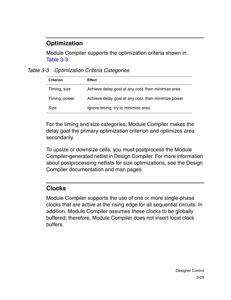
Optimization
Module Compiler supports the optimization criteria shown in Table 3-3.
For the timing and size categories, Module Compiler makes the delay goal the primary optimization criterion and optimizes area secondarily.
To upsize or downsize cells, you must postprocess the Module Compiler-generated netlist in Design Compiler. For more information about postprocessing netlists for size optimizations, see the Design Compiler documentation and man pages.
Clocks
Module Compiler supports the use of one or more single-phase clocks that are active at the rising edge for all sequential circuits. In addition, Module Compiler assumes these clocks to be globally buffered; therefore, Module Compiler does not insert local clock buffers.
Table 3-3 Optimization Criteria Categories
Criterion Effect
Timing, size Achieve delay goal at any cost, then minimize area
Timing, power Achieve delay goal at any cost, then minimize power
Size Ignore timing; try to minimize area
3-29
Designer Control

This approach is consistent with ASIC design methodologies that cannot implement multiple clocks with very low skew. A pure combinational design has no clocks, whereas sequential circuits typically have a single clock, named CLK.
In some cases, you are allowed to partition the design into groups with different clocks. Module Compiler highly restricts the use of multiple clocks. Automatic latency skewing is not permitted between signals generated with different clocks.
If you pipeline signals from different clocks before interacting, you must employ latency hiding. Also, because Module Compiler ignores skews between clocks, timing information Module Compiler provides might not be accurate in all cases.
The default clock signal is CLK. A clock trunk or a clock buffer tree is generated during place and route. Module Compiler supports the following user-defined features:
• The clock can be specified as an input signal.
• The clock can appear in the module interface.
• The clock must be a 1-bit unsigned signal.
• There is no restriction on naming conventions for the clock.
• You can gate the clock, but the resulting signal cannot be used as a clock.
Note: You can specify the default clock signal to something other than CLK with the Module Compiler environment variable dp_default_clockname.
3-30
Chapter 3: Key Concepts and Constraints

External Constraints
Module Compiler supports external circuits, at both the input and the output of the synthesized circuit, through external constraints. At the input, you can specify the maximum allowed load for each input operand, to match the loading constraints of the driver.
You can also specify arrival times to represent any delay incurred in the external circuit, using the indelay attribute. At the output, you can specify a load to represent the input loading of the following circuit, using the outload attribute. Finally, you can specify a delay to represent delays expected by the following circuit, using the outdelay attribute.
Testing
Module Compiler supports scan test methodologies implemented by a third-party tool. Although Module Compiler does not wire the scan chain or generate the test vector, it attempts to anticipate changes due to scan chain insertion.
When Module Compiler operates in scan mode, it converts all simple and enabled D-type flip-flops to scan registers during synthesis. This ensures that it uses the correct area and timing estimates during synthesis and optimization.
After it writes the design report and before it writes the netlist, Module Compiler converts the scan flip-flops back to D-type flip-flops. It also generates a text file that lists instances of D-type flip-flops and their scan equivalents. This file is in the scan directory. Module Compiler supports synthesized as well as instantiated flip-flops. See also “Scan Test” on page 6-47.
3-31
Designer Control
Naming
You can control the verbosity of instance and net names by choosing Use Groups Names in the Synthesis menu and Sim Debug Mode on the Reports menu. When Sim Debug Mode is turned on, debugging the netlist becomes easier. Instances and net names are meaningful in both layout and simulation. For a discussion of naming issues in Module Compiler, see “Naming” on page 8-12.
Degenerate Cases
To improve productivity, Module Compiler handles degenerate cases efficiently. It handles several types of degeneration, including missing data and constants.
Module Compiler handles missing data for degenerate cases efficiently. Here, all Wallace-tree-based functions take any number of inputs, including 0, in any bit position. You do not need to be concerned that with one signal input and another input tied to 0, the sum will result in an adder.
In addition, the use of bit ranges and constant shifts causes data to get lost. This is not a concern, because with Module Compiler, the structures adapt to the loss of the data to create the smallest and highest-performance structure possible.
With Module Compiler, many synthesis functions optimize the constants as a special case, providing the greatest optimization.
3-32
Chapter 3: Key Concepts and Constraints

For example, multiplying two constants results in no instances, whereas multiplying a variable signal by a constant results in a circuit that is smaller and faster than a two-variable signal multiplier. Module Compiler can optimize even partially constant signals (those with some bits that are variable and some that are constant).
3-33
Designer Control

3-34
Chapter 3: Key Concepts and Constraints

4Graphical User Interface 4
This chapter describes the Module Compiler GUI. It includes the following sections:
• GUI Overview
• Action Buttons
• Module Compiler Input Fields
• File Menu (File Manipulation and Sessions)
• Synthesis Menu
• Optimization Menu
• Reports Menu (Report Generation)
• View Menu (Module Compiler Output)
• Build Menu
4-1

• Library Menu (Module Compiler Library Options)
• Options Menu (Module Compiler General Options)
• Help Menu
• Graphical User Interface Shortcuts
4-2
Chapter 4: Graphical User Interface

GUI Overview
The GUI consists of a permanent main window, transient dialog boxes, and text and error windows. The main window, shown in Figure 4-1, appears when you start Module Compiler. The main window consists of the menu bar, the action buttons, the input fields, the status window, and the log window. Each of these sections is discussed briefly. Some are discussed, in later sections, in more detail.
Figure 4-1 The Module Compiler Main Window
Use the menu bar (Figure 4-2) to select files to synthesize; to initiate an action; to get online help; to control the GUI environment; and to set options for synthesis, optimization, and report generation. The menus dim when they are not available.
Menu bar
Action buttons
Input fields
Status window
Log window
4-3
GUI Overview

Figure 4-2 Menu Bar
Click the action buttons Synthesize, Optimize, Gen Reports, or Do All (Figure 4-3) to start a step in Module Compiler. The Abort button cancels a step in progress. It dims when there is no interruptible activity in progress. For more information, see “Action Buttons” on page 4-6.
Figure 4-3 Action Buttons
Use the input fields (Figure 4-4) to specify
• Files to compile
• Parameters to use during synthesis
• Optimization criteria to use
• The parameter iteration file (optional)
Figure 4-4 Input Fields
4-4
Chapter 4: Graphical User Interface

Use the status window (Figure 4-5) to indicate the progress of the current step and to display library and operating condition information.
Figure 4-5 The Status Window
The log window (Figure 4-6) is a text window embedded within the main window. It contains a running log of all operations. You can use the scroll bars to review messages that have scrolled out of view, or you can resize the window. Module Compiler clears this window automatically with each synthesis operation.
Figure 4-6 The Log Window
4-5
GUI Overview

Action Buttons
Click the Synthesize, Optimize, Gen Reports, or Do All button (Figure 4-3 on page 4-4) to initiate an action in Module Compiler. Synthesize and Optimize cause the circuit to be synthesized or optimized. Gen Reports generates the reports you have chosen from the Reports menu.
Do All causes all three operations to be performed in order, and clicking it is a convenient way for you to generate reports after making an input-file or parameter change. When Module Compiler is busy, the action buttons dim and the Abort button becomes available to allow you to interrupt the processes. You can also access these actions from the Build menu.
Module Compiler Input Fields
Use the input area of the main window (Figure 4-4 on page 4-4) to set which files to synthesize, the parameters for synthesis, and the synthesis optimization criterion.
The following text boxes are available in the input area of the main window:
Input File(s)
Names the design description files that describe the module to be synthesized. You can enter the file name or choose the Find Input File from the File menu to open a browser to select the files. Specify multiple files as a comma-separated list, without space between entries.
4-6
Chapter 4: Graphical User Interface
Parameters
Specifies input parameters, which are parameters that the module expects in your input. For instance, if the module has an integer parameter called width and you want to pass in 8 as the value, you enter the following string in this field:
width=8
If there are no parameters, leave the field blank or set it to a hyphen (-). To specify more than one parameter, separate the parameters with commas:
width=8,name=test
The parameter list must not contain any spaces.
To retrieve the parameters and any defaults from the current input file, choose Get Parameters from the File menu.
Optimization
Specifies the optimization criterion. Use one of the values in Table 4-1. In these values, delay is an integer representing the delay goal, in picoseconds. You can override this value by using the delay directive in your design description.
Par Iter File (Parameter Iteration File)
Names the parameter iteration file that contains the sets of parameter values Module Compiler uses for synthesis. See the Module Compiler Reference Manual for a detailed description of
4-7
Module Compiler Input Fields

the param function and the parameter iteration file. If there is no parameter iteration file, leave the field blank or set it to a hyphen (-).
The rest of this chapter discusses each menu, from File to Help.
Table 4-1 Optimization Criterion Values
Value Effect
speed Try to generate the fastest circuit possible
area Ignore timing; minimize area
speed, area Same as speed, but consider area when breaking ties
Delay_in_ps Try to achieve the specified delay, in ps
Delay_in_ps, area Same as delay; minimize area when there is slack
4-8
Chapter 4: Graphical User Interface
File Menu (File Manipulation and Sessions)
The File menu (Figure 4-7) provides several shortcuts for
• Defining and controlling Module Compiler sessions
• Selecting, editing, and retrieving the parameters from the input files
Defining and Controlling Sessions
A session is a set of all settings in the GUI, including the preferences for the GUI and the synthesis, optimization, and report options. You can define as many sessions as you need. For example, you can define a session for the top level and for each block of the design.
You can use a session for each parameterization of a block, or you can define one session for a quick estimate and another for a full optimization of the same block. You can even choose to ignore sessions altogether.
Module Compiler warns you if you attempt to discard any changed settings by exiting Module Compiler or loading a new session. When you restart Module Compiler, it automatically reloads the last active session.
4-9
File Menu (File Manipulation and Sessions)

Setting Options
Figure 4-7 The File Menu
The File menu contains the following items for manipulating input files and setting options:
Edit Input File
Chooses an input file from the submenu and opens the file in a text editor.
4-10
Chapter 4: Graphical User Interface

Note:
The default editor is vi. You can change this default by setting the dp_editor Module Compiler environment variable. For example, you can set your default editor to emacs by executing the following command:
% mcenv dp_editor emacs
For more information about Module Compiler environment variables, see the Module Compiler Reference Manual.
Find Input File
Opens the file browser to locate a file to edit. When you select a file, Module Compiler appends it to the list of files in the Input File(s) entry area.
Session (none)
Chooses a session operation from the submenu. You can save the current settings under the current name with Save or under a new name with Save As. Enter the session name, or use a file name with a .dps extension. Use Load to choose one of the already saved sessions on the submenu.
Flatten Input
Removes all macros, function calls (except library functions), replicates, conditions, and integers. You can also see how Module Compiler creates and declares temporary variables for complex expressions. Module Compiler displaces the flattened output in the log window. Use this mode to better understand how Module Compiler breaks the description into a set of synthesizable expressions and functions.
4-11
File Menu (File Manipulation and Sessions)

Get Parameters
Retrieves the parameters with any default values from the current input file. This option is useful if the design has many parameters that are difficult to remember. When retrieving parameters, Module Compiler ignores all parsing errors.
MCE
Chooses a Module Compiler Express function for synthesis. Use this option to quickly generate blocks already available in Module Compiler Express, which eliminates the need to write Module Compiler Language code for these blocks.
Parameters you enter for Module Compiler Express functions are saved automatically, function by function, and are recalled automatically when you select the function later. For more information, see the online help that is available for all Module Compiler Express blocks.
To use the floating-point functions DW_mult_fp, DW_add_fp, DW_comp_fp, DW_i2flt_fp, and DW_i2flt_fp, you need an MC-Pro and a DesignWare license. For more information on DesignWare licenses, installation, and function usage, use the search capability at: http://www.synopsys.com/ipdirectory.
Library Browser
Shows all cells available in the currently loaded technology library and all foreign cells and netlists loaded from the Module Compiler command line. Module Compiler groups cells by categories, putting the user netlists and foreign cells in the “misc” category.
4-12
Chapter 4: Graphical User Interface

When you select a cell in the library browser, the status area of the main window displays the interface and function (if available) for the cell. Each cell or netlist is available in Module Compiler as a function for instantiation in the Module Compiler Language design.
Exit MC
Exits Module Compiler. If you have changed some session settings without saving, Module Compiler warns you before it exits.
Synthesis Menu
After choosing the input files and parameters, you must set synthesis options, using the Synthesis menu (Figure 4-8), before Module Compiler can begin circuit synthesis.
Figure 4-8 The Synthesis Menu
4-13
Synthesis Menu

The Synthesis menu contains the following items:
Pipeline
Enables/disables the automatic pipelining default. You can override this value by using the pipeline directive in the input file.
Scan Test Mode
Enables/disables scan test mode. For more information on scan test mode, see “Scan Test” on page 6-47.
Use Group Names
Toggles whether to prefix instance names with the name of the group to which they belong. Longer names make it easier to plan and to debug the results.
Top Level Mode
Indicates whether the design is a full chip that contains I/Os. Module Compiler checks I/O connection rules in both modes.
Continue on Warnings
Toggles whether Module Compiler interrupts the synthesis process when it encounters warning conditions. In general, it is a good idea to set Module Compiler to stop when it encounters a warning condition.
Build Regular Trees
Toggles whether Module Compiler should try to maximize the regularity of structures used to build various operators during synthesis.
Language
Displays the Strict Parsing submenu for controlling language parser options.
4-14
Chapter 4: Graphical User Interface

Strict Parsing Submenu:
Toggles whether to display warnings when Module Compiler encounters obsolete constructs in the Module Compiler input file and when size or format mismatches occur in function calls. It is a good idea to leave this option enabled.
More Options
The More Options menu item displays a dialog box (Figure 4-9) in which you set defaults for several synthesis options. You can override these values by using a directive statement in an input file.
Figure 4-9 The Module Compiler Synthesis Options Dialog Box
The Module Compiler Synthesis Options dialog box contains the following fields for controlling the synthesis process:
Include Path
Sets the search path for any files included in the input file. Normally you set this field to dot (.) to indicate the current directory. You can specify an alternative list of directories; use a colon (:) to separate items in the list. If your design includes any files, Module Compiler searches these directories sequentially.
4-15
Synthesis Menu

Max Input Load
Sets the default value for maximum input loading. You can override this value by using the inload directive, as described in “I/O Constraints” on page 6-4. The unit is 0.1 standard load.
Output Load
Sets the default value for the external loading on the output. You can override this value by using the outload directive. The unit is 0.1 standard load.
Pipeline Slack
Adjusts the delay goal for automatic pipelining stages. The new pipeline delay goal becomes
pipeline delay = delay - pipeline slack
The pipeline slack is specified in picoseconds. A positive value forces the pipelines closer together, whereas a negative value forces the pipelines farther apart.
Synthesis Status Display
Select Synthesize to perform initial synthesis of the netlist from the input file(s). The synthesis progress is displayed on the set of status bars shown in Figure 4-10. The Lines (%) status bar indicates how much of the flattened input file has been processed.
The Area, Latency, and FFs status bars indicate, respectively, the total area, the maximum latency, and the number of flip-flops currently in the design.
To set the maximum limits for the status bars, use the Options menu in the main window.
4-16
Chapter 4: Graphical User Interface
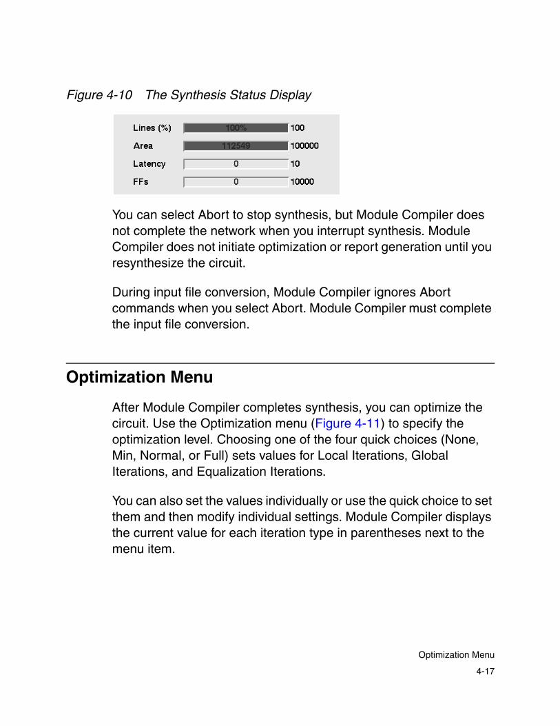
Figure 4-10 The Synthesis Status Display
You can select Abort to stop synthesis, but Module Compiler does not complete the network when you interrupt synthesis. Module Compiler does not initiate optimization or report generation until you resynthesize the circuit.
During input file conversion, Module Compiler ignores Abort commands when you select Abort. Module Compiler must complete the input file conversion.
Optimization Menu
After Module Compiler completes synthesis, you can optimize the circuit. Use the Optimization menu (Figure 4-11) to specify the optimization level. Choosing one of the four quick choices (None, Min, Normal, or Full) sets values for Local Iterations, Global Iterations, and Equalization Iterations.
You can also set the values individually or use the quick choice to set them and then modify individual settings. Module Compiler displays the current value for each iteration type in parentheses next to the menu item.
4-17
Optimization Menu

Figure 4-11 The Optimization Menu
The Optimization menu contains the following items for manipulating the optimization process:
None, Min, Normal, and Full
Choosing one of these items sets values for Local Iterations, Global Iterations, and Equalization Iterations. The values assigned appear in parentheses next to the menu items.
For most purposes, choosing one of these four items (None, Min, Normal, or Full) is sufficient. Choosing None bypasses optimization by setting all four values to 0. Selecting Full maximizes optimization. Normal is a good choice for most circuits.
4-18
Chapter 4: Graphical User Interface

Local Iterations
Sets the maximum number of local iterations allowed for each step. This is the maximum number of times Module Compiler tries a step before going to the next one. Module Compiler terminates an optimization step if it makes no further progress.
Global Iterations
Sets the number of global iterations Module Compiler performs. Module Compiler performs all selected optimization steps as a group the number of times you specify. Global iterations always continue until Module Compiler performs all global iterations, regardless of whether it makes progress.
Equalization Iterations
Sets the number of global iterations (at the end of the process) that employ equalization. When Module Compiler cannot meet the original goal, equalization allows the use of a relaxed delay goal (the current critical path) rather than the original goal.
Global Equalization
When you enable Global Equalization, Module Compiler sets the delay goal equal to the largest delay within a timing group when the original delay goal cannot be met. When you disable Global Equalization, Module Compiler employs local equalization and sets the delay goal equal to the largest delay within a group.
Flatten Pseudo Cells
Flattens pseudocells to their technology library equivalent following the synthesis step. If you deselect this option, pseudocells are not mapped and they remain in all of the netlists. Turning off this option is useful for performing pseudocell usage analysis on the design.
4-19
Optimization Menu

Allow Pseudo Cells in Opt
Module Compiler, by default, does not allow pseudocells in optimization. When you select this option, Module Compiler checks to see if equivalent pseudocells give a better optimization than native technology library cells, If so, the technology library cells are replaced by better equivalent pseudocell mapping.
Steps
Displays the Steps submenu, as shown in Figure 4-12 and defined in Table 8-7 on page 8-64. You choose menu items to specify the optimization steps Module Compiler performs. The text label is the integer code representing all the currently selected optimization steps. You can use this integer value in command-line mode (by using the -opt option) to turn on the same optimization steps.
It is usually a good idea to select all options, even though this can prolong optimization for large designs.
You can specify the optimization steps to be executed but not the order in which Module Compiler executes them. For more information, see “Optimization” on page 8-63.
4-20
Chapter 4: Graphical User Interface

Figure 4-12 The Steps Submenu
Flatten Pseudo Cells
Flattens pseudocells. Deselect to prevent Module Compiler from flattening pseudocells.
4-21
Optimization Menu

Retime
Sets the retime effort level. The retiming function processes existing pipeline registers in your design. Retiming does not turn on automatic pipelining or create pipeline registers in your design. For more information, see “Design Retiming in Design Compiler” on page 10-3.
Automatic input registering
Enables automatic input registering. For more information, see “Automatic Input and Output Registering” on page 10-4.
Automatic output registering
Enables automatic output registering. For more information, see “Automatic Input and Output Registering” on page 10-4.
Design Compiler
Displays the Design Compiler submenu, as shown in Figure 4-13.
4-22
Chapter 4: Graphical User Interface
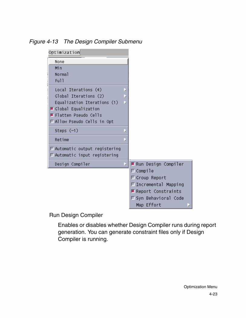
Figure 4-13 The Design Compiler Submenu
Run Design Compiler
Enables or disables whether Design Compiler runs during report generation. You can generate constraint files only if Design Compiler is running.
4-23
Optimization Menu

Compile
Toggles whether you want to perform the compile within Design Compiler. Select this option if you want to optimize the circuit with Design Compiler.
Group Report
Normally Design Compiler generates only the critical path for the design. Selecting this option causes Design Compiler to report a critical path for each group in the design.
Design Compiler analyzes the critical paths before compiling a circuit, because it changes the instance names during optimization. This option can be useful when you use Design Compiler to analyze a Module Compiler design after place and route.
Incremental Mapping
Enables or disables incremental mapping by Design Compiler. Generally, when you enable incremental mapping, you reduce Design Compiler runtime and Design Compiler makes fewer changes in the circuit structure.
Report Constraints
Enables or disables the report_constraints command within Design Compiler.
Syn Behavioral Code
Selects the type of Module Compiler output code to use as input for Design Compiler. Selecting this option specifies Module Compiler behavioral-level code; deselecting the option specifies Module Compiler gate-level code.
4-24
Chapter 4: Graphical User Interface

Map Effort
Displays a submenu. You can choose Low, Medium, or High for the mapping effort. In general, the higher the mapping effort, the greater the runtime and the quality of results.
Optimization Status Display
To perform optimization, click the Optimize button. During optimization, Module Compiler displays the progress as a series of bar graphs, as shown in Figure 4-14. This type of display lets you gauge the effectiveness of the optimization process and determine the progress toward your design goals.
Module Compiler displays negative slack values (delay goal not met) in red and positive values in blue. There are three bar graphs: Slack, Area, and Instances. Module Compiler displays the current optimization step and delay above the bar graphs.
Figure 4-14 The Optimization Status Display
Click the Abort button to stop the optimization process. Module Compiler always completes the current optimization step before it cancels the process. This ensures that Module Compiler completes
4-25
Optimization Menu
the netlist so that after the cancellation, Module Compiler generates a valid design. Of course, the netlist might be suboptimal if you cancel optimization.
During optimization, Module Compiler sends information to the log window, indicating the timing, area, netlist changes, and critical group for each optimization step.
Reports Menu (Report Generation)
Except as noted, Module Compiler generates all files when you click the Gen Reports button. Module Compiler displays each file in a text window that can be resized and scrolled. In addition, each window has a Find Top button that brings the main window back to the top of the display.
Module Compiler can generate several different reports after any successful synthesis or optimization operation. Use the Reports menu (Figure 4-15) to choose which report files to generate. After you have generated a report file, you can select and view it from the View menu.
See Chapter 8, “Analysis and Optimization,” for a description of the various output files of Module Compiler and suggestions for using these files to interpret your results and to plan further design refinements.
4-26
Chapter 4: Graphical User Interface
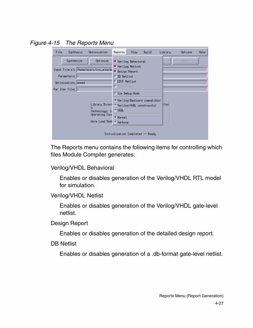
Figure 4-15 The Reports Menu
The Reports menu contains the following items for controlling which files Module Compiler generates:
Verilog/VHDL Behavioral
Enables or disables generation of the Verilog/VHDL RTL model for simulation.
Verilog/VHDL Netlist
Enables or disables generation of the Verilog/VHDL gate-level netlist.
Design Report
Enables or disables generation of the detailed design report.
DB Netlist
Enables or disables generation of a .db-format gate-level netlist.
4-27
Reports Menu (Report Generation)

Note:
The gate-level netlist (.db) created by Module Compiler does not contain design constraints, such as timing constraints. If you want to include such constraints in the .db, you can read the Module Compiler-created .db into Design Compiler or Physical Compiler, apply your constraints, and write out the .db file again. This new .db file then contains the appropriate constraint information.
EDIF Netlist
Enables or disables generation of the EDIF gate-level netlist.
Sim Debug Mode
Enables or disables the use of debugging names in the netlist models. When you select this mode, Module Compiler uses long instance names that include the operand, bit position, and cell name. When you deselect it, all instance names start with I and end with a unique number.
Deselect this mode before going to place and route, because the long names it creates can cause problems for future verification. The Use Group Names item (on the Synthesis menu) is independent of this option and controls the insertion of the group name at the beginning of the instance name.
Verilog(Backward compatible)
Selects the language to be used for generating behavioral- and gate-level output. Verilog(Backward compatible) sets the output language to Verilog.
Verilog(VHDL constraints)
Sets the output language to Verilog, following VHDL naming constraints.
4-28
Chapter 4: Graphical User Interface

VHDL
Sets the output language to VHDL.
Normal/Verbose
Selects either Normal or Verbose output. Verbose mode provides more information about errors, warnings, and status information in the Module Compiler log file. Normal mode is recommended except for debugging.
Messages generated with the info function appear only in Verbose mode. Contextual information from HDL code is available only in Verbose mode.
View Menu (Module Compiler Output)
Use the View menu (Figure 4-16) to view generated reports. Module Compiler dims reports in the menu that are not available.
When you select any of the reports, a text window opens, showing the requested information. Module Compiler automatically updates text windows whenever it performs an operation that changes their contents.
Only one text viewer of each type can be open at a time. Selecting the item for a viewer that is already open brings the existing viewer to the top of the display stack.
See “Module Compiler Output Files” on page 8-2 for a description of the various Module Compiler output files, including suggestions for using these files to interpret your results and plan further design refinements.
4-29
View Menu (Module Compiler Output)

Figure 4-16 The View Menu
The View menu contains the following items:
Stats
Displays a design summary. It is available whenever a valid netlist exists. This report is the same as the report in the .dp_ds file.
Critical Path
Displays the most critical path in the design. It is available whenever a valid netlist exists. This report is the same as the report in the .dp_cp file.
4-30
Chapter 4: Graphical User Interface

User Critical Paths
Displays any user-defined critical paths in the design. This report is the same as the report in the .dp_ucp file.
I/O Summary
Displays a summary of loading and timing for each bit of every input and output operand. This report is the same as the report in the .dp_rio file.
Cell Summary
Displays a summary of cells used in the design. Module Compiler reports cell usage by type (RAM, combinational, I/O, or flip-flop). It sorts the listings by name and percentage of area each cell type uses. This report is the same as the report in the .dp_cells file.
Table Summary
Displays the running summary, showing brief results for previous Module Compiler runs. Module Compiler shows the area, delay, latency, and parameters for each run, with the last-generated design at the top. You have the option of sorting results by area, delay, area-delay, product, or latency. This report is the same as the report in the table file.
Design Report
Displays the detailed design report. This report contains group and design summaries, critical path information, the I/O summary, the clock/pipeline stall summary, the operand summary, and the cell summary. This report is the same as the report in the module_name.report file.
4-31
View Menu (Module Compiler Output)

Verilog/VHDL Netlist
Displays the gate-level netlist. Depending on the output language setting, the netlist is in the <module_name>.vrl Verilog file or the module_name.vhd VHDL file.
Verilog/VHDL Behavioral
Displays the behavioral-level simulation model. Module Compiler generates the RTL model during the initial synthesis step. Depending on the output language setting, the simulation model is in the <module_name>.bvrl Verilog file or the module_name.bvhd VHDL file.
Datasheets
This option is obsolete and is being removed.
EDIF Netlist
Displays the gate-level EDIF netlist. The netlist is contained in the module_name.edif file.
Conditions
Displays the technology, technology library directory, wire load model, and current operating conditions in the status window.
Design Compiler Report
Displays the Design Compiler reports after postprocessing of the netlist in Design Compiler.
Design Compiler Output Netlist
Displays the netlist produced by postprocessing the design in Design Compiler. Depending on the output language setting, the the postprocessed netlist is contained in the module_name.dc.vrl Verilog file or the module_name.dc.vhd VHDL file.
4-32
Chapter 4: Graphical User Interface

Library Report
Displays information about the currently loaded technology library and the mapping of generic Module Compiler cells to specific vendor-provided cells.
Clear Summary
Clears the table summary and resets the table file.
Clear Log
Clears the log window.
Build Menu
The Build menu (Figure 4-17) provides the operations you need for building your design. These operations, except for Initialize, are also available on the buttons just below the menu bar.
Figure 4-17 The Build Menu
4-33
Build Menu

The Build menu contains the following items:
Initialize
Reads in the technology library, if Module Compiler has not already read it. Module Compiler initializes automatically when you invoke it, so you do not normally need this option. When Module Compiler is already initialized, choosing this menu item has no effect.
Synthesize
Causes Module Compiler to synthesize the circuit. Choosing this menu item is the same as clicking the Synthesize button.
Optimize
Causes Module Compiler to optimize the circuit. Choosing this menu item is the same as clicking the Optimize button.
Output
Generates the reports you have chosen from the Reports menu. To see a report, choose it from the View menu. Choosing this menu item is the same as clicking the Gen Reports button.
Do All
Performs synthesis, optimization, and report generation—in that order—and is convenient for generating reports after making an input-file or parameter change.
4-34
Chapter 4: Graphical User Interface

Library Menu (Module Compiler Library Options)
The Library menu displays the Module Compiler Library Options dialog box (Figure 4-18), which shows information about the currently loaded technology library and allows you to set the operating conditions and the wire load model.
Figure 4-18 The Module Compiler Library Options Dialog Box
The Module Compiler Library Options dialog box contains the following items:
Technology
Displays the name of the currently loaded technology library.
Library Dir
Displays the name of the directory that contains the technology library files.
4-35
Library Menu (Module Compiler Library Options)

Tree Type
Sets the wire resistance to Auto, Best Case, Balanced, or Worst Case. The default setting is Auto, with which Module Compiler looks at the operating conditions in your library to set the case.
Wire Load Model
Shows the name of the current wire load model. To change the model, enter a new name. If you enter in a model name that is not in the current vendor library, Module Compiler displays a list of available models. You can find detailed information about what’s available in the current vendor’s technology library by choosing Library Report from the View menu.
Operating Condition
Specifies the conditions (slow, typ, fast) under which the chip is likely to be used. Select one operating condition.
Named Opcond
Specifies which model in the technology library is associated with each of the Operating Condition buttons. For example, as shown in Figure 4-18, WCCOM is associated with slow.
Process, Voltage, and Temp
These items display the process, voltage, and temperature values assigned to each named opcond.
4-36
Chapter 4: Graphical User Interface

Options Menu (Module Compiler General Options)
You specify general setup and GUI options in the Module Compiler General Options dialog box, shown in Figure 4-19. Choose Options from the main menu bar to display the dialog box.
Figure 4-19 The Module Compiler General Options Dialog Box
The Module Compiler General Options dialog box contains the following items:
Log File
Enter the name of the file for recording log messages. Unless you enter a hyphen (-) as the file name, Module Compiler copies all messages sent to the log window to this file.
Max Messages
Enter a limit on the number of similar messages to print before giving up. Use this option to keep large numbers of similar messages from filling the log window, but be aware that you might mask other important messages in the process.
4-37
Options Menu (Module Compiler General Options)

Display Max Area
Enter the maximum number of area units for the synthesis status display.
Display Max Latency
Enter the maximum latency for the synthesis status display.
Display Max FF
Enter the maximum number of flip-flops for the synthesis status display.
Display Num Bars
Enter the maximum number of bars that can be displayed in each optimization status bar graph (see Figure 4-14 on page 4-25).
Log Window Height
Enter the height of the log window, in characters. To remove the window, enter 0. This value takes effect the next time Module Compiler sends data to the log window. Manually resizing the window overrides this value. For large or complex designs, large log windows in conjunction with Verbose mode might significantly slow down synthesis.
4-38
Chapter 4: Graphical User Interface

Help Menu
The Help menu provides brief online information about menu bar items. Selecting any help item activates a text viewing window for that topic.
Figure 4-20 The Help Menu
Graphical User Interface Shortcuts
Table 4-2 presents keyboard shortcuts and other editing actions.
Table 4-2 Keyboard Shortcuts and Other Editing Actions
Shortcut Action
Control-b or Left Arrow key
Moves the cursor left one character
Control-f or Right Arrow key
Moves the cursor right one character
Control-a Moves the cursor to the beginning of the line
Control-e Moves the cursor to the end of the line
Control-d Deletes one character to the right of the cursor
4-39
Help Menu

Control-h Deletes one character to the left of the cursor
Control-i Inserts a tab
Control-w Deletes the selected text
Control-k Deletes text from the cursor to the end of the line
Control-u Deletes entire line
Left-clicking the mouse
Changes insertion point
Pressing and holding down the middle mouse button while dragging
Scrolls the text
Table 4-2 Keyboard Shortcuts and Other Editing Actions (Continued)
Shortcut Action
4-40
Chapter 4: Graphical User Interface

5Module Compiler Language Guide 5
This chapter describes the general makeup and constructs of Module Compiler Language. It includes the following sections:
• Module Compiler Language Overview
• General Layout of the Input
• Modules
• Variables, Operators, and Expressions
• Attributes and Directives
• Macro Preprocessor
• Input Flow Control
• Functions
5-1

• Built-in Functions
• Messages
5-2
Chapter 5: Module Compiler Language Guide

Module Compiler Language Overview
Using Module Compiler Language is the way to provide a high-level description of your design to Module Compiler. Module Compiler Language is a hardware description language that describes the functionality of the circuit and, through the use of directives, can also control how a circuit is synthesized and optimized.
Module Compiler Language has the look and feel of Verilog, but it has some differences. As a newer technology, Module Compiler Language specifically addresses datapath synthesis, optimization, and reuse needs. It also has new constructs and operators not found in Verilog that are useful for datapath design. Module Compiler Language borrows from the C programming language. For writing Module Compiler Language, prior experience with C is helpful but not necessary.
General Layout of the Input
In its most general form, input to Module Compiler consists of one or more files containing Module Compiler Language code. These files contain a high-level description of the design to be synthesized and optimized. Logically, these files appear as one input stream. If you concatenated the files, you would get a single description.
A Module Compiler Language file (see Figure 5-1) might have one or more of the sections shown below.
5-3
Module Compiler Language Overview

Figure 5-1 Module Compiler Language File
• Macro definitions
Macro definitions implement preprocessing constructs. Although the example above groups them, they might appear anywhere in the file.
• Comments
Text enclosed by /* */ and everything to the right of // in a line is considered a comment. Comments can appear anywhere in the input.
Macro
Comment
definitions
Moduledefinition
Functiondefinitions
Comment
#define MAX 128#define MIN MAX - 64
...
/* the following is a module definitionname test_main */
module test_main (arg1, arg2, ...);...endmodule
//functions f1 - fn are defined here
function f1(arg1, arg2, ...);...endfunction
function f2(arg1, arg2, ...);...endfunction
5-4
Chapter 5: Module Compiler Language Guide
• Module definition
A module definition is a description of the design to be synthesized. An input that does not contain a module is an empty input, which synthesizes nothing.
A module is the Module Compiler Language analog of main() in a C program. A module can appear anywhere in the input, but it must not contain or overlap a function.
• Function definitions
You can call these pieces of encapsulated code from the module or from inside other functions. Functions are operations grouped into a named abstract object, which you can later refer to by its name. Because they are abstract objects, functions do not appear as groups or as other hierarchical entities in the output.
A function is the Module Compiler Language analog of a procedure in a C program. A function can appear anywhere in the input, but it must not overlap a module or any other function.
The following sections describe these constructs and the Module Compiler Language in more detail.
5-5
General Layout of the Input
Modules
A module definition is the description of the design that Module Compiler synthesizes. The description begins with module and ends with endmodule, as illustrated in Example 5-1.
Example 5-1 Sum of Inputs
module test (Z, X, Y); //module interface output [8] Z; //declare the outputinput [8] X, Y; //declare the inputsZ = X + Y; //sum!
endmodule
In Example 5-1, the module statement
module test (Z, X, Y);
describes the interface to the design. The rest of the module definition,
output [8] Z;input [8] X, Y;Z = X + Y;
specifies the content of the design. As mentioned above, module is the Module Compiler Language equivalent of main() in the C language. You can write a simple adder in Module Compiler Language, as shown in Example 5-1.
Example 5-1 generates an adder cell that takes two 8-bit inputs (X and Y) and provides one 8-bit output (Z). The list of arguments (Z, X, Y) is the interface specification for the module.
In Module Compiler Language, the arguments can appear in any order. There is no restriction on the number of arguments.
5-6
Chapter 5: Module Compiler Language Guide

Like many other structured programming languages, Module Compiler Language requires that you declare a variable before it is accessed. Similarly, you need to declare the arguments for a module before they are referenced (see Table 5-1).
The input statement declares a signal input for a module. The output statement declares the output for a module. These signals must have a width and can be assigned a signed or unsigned format. If you do not assign a format, Module Compiler takes unsigned as the default.
The wire statement also declares a signal. This signal is not an input or an output but is internal to the module.
The module definition itself consists of one or more statements. The definition ends with the endmodule keyword.
Note that as in Verilog, there is no semicolon after endmodule, whereas most other statements end in a semicolon. In Module Compiler Language, the presence of a semicolon after endmodule results in a parsing error. The statements that make up a module do one of the following:
• Declare a variable
• Compute something and assign it to a variable
Table 5-1 Examples of Module Argument Declarations
output unsigned [8] A, B; Unsigned 8-bit-wide outputs A, B
output [8] a, b; 8-bit-wide outputs a and b, unsigned by default
input signed [16] X, Y; Signed 16-bit inputs X and Y
input [1] xxx, yyy; Unsigned 1-bit inputs xxx and yyy
5-7
Modules
• Set a directive
• Print a message
These groups of statements are described in more detail in the following sections.
It is possible to write arbitrarily complex input descriptions, using a module alone, one without any hierarchical abstraction of groups of operations. However, code written in this way is not suitable for design reuse, which is an important design goal.
A more effective approach is to build a set of functions that can then be called to build this module (or another module that happens to require the same functions). See “Functions” later in this chapter.
Variables, Operators, and Expressions
Most operations in Module Compiler Language involve some variables and operators. All variables must obey the following rules:
• Variables must be declared before use.
• Variable names must begin with a letter and can contain only alphanumeric characters and underlines (_). Underlines must be separated by at least one other character.
• Variable names must not be the same as keywords in the language or the same as symbol names (names of functions, cells, and so on).
Module Compiler Language supports variables of several types. You use operators to combine variables into expressions.
5-8
Chapter 5: Module Compiler Language Guide

Signal Variables
Module input, output, and wire declaration statements are used to declare signal variables. In addition to the general rules, signal variables must obey the following rules:
• A continuous time path from a signal variable to itself must pass through a sequential element or a feedback input of a function.
With this restriction, Module Compiler can sort the network for synthesis. If a path from a variable to itself does not pass through a sequential element or a feedback input, Module Compiler cannot synthesize the circuit and generates an error message.
• You can make an assignment to a signal variable only once. Therefore, a variable can appear on the left side of an equality only once and it is not possible to assign a bit range to a variable.
• Signal variables must have a width before Module Compiler uses them in an expression. Therefore, although Example 5-2 is syntactically correct, it semantically has no meaning.
Incorrect: creates a loop from Z to Z
Correct, because X is an input
wire [8] X, Z;Z = Z + 10; input [8] X; wire [8] Z;Z = X + 10;
5-9
Variables, Operators, and Expressions

Example 5-2 Signal Variable Width
wire [8] Z;wire X; Z = X + 10 //ERROR: X must have a width
• Signal declarations without a width are a useful construct, which is further explained in the “Signal Outputs” section later in this chapter.
• Note that X in Example 5-2 does not have a 1-bit width, as it would in Verilog.
• In Module Compiler Language, X is treated as a signal with no defined width, which flags an error in Module Compiler Language.
• The + operator is one of several signal operators you can use to combine signal variables into expressions.
A datapath is actually no more than a series of these signal expressions. Most of these operators should be familiar to users of common programming or behavioral modeling languages.
5-10
Chapter 5: Module Compiler Language Guide

Module Compiler Language has some unique operators, such as >>>. Where applicable, these unique operators follow the precedence rules of the C language, which are the same as those in Verilog. In Table 5-2, the operators are listed in order of decreasing precedence.
Operators on the same line have the same precedence. When Module Compiler encounters operators of the same precedence in a Module Compiler Language file, it processes them from left to right.
Table 5-2 Signal Operators
Signal operator Name
(width) Casting
[ ] Bit range
( ) Expression grouping
- ∼ (Unary) arithmetic negate, bitwise invert
∗ Multiply
+ − Add, binary minus
<<< >>> Left, right rotate
<< >> Left, right shift
< > <= >= Magnitude comparison
== ! = Equality, inequality compare
& Bitwise AND
^ Bitwise XOR
| Bitwise OR
? : Multiplex (MUX)
5-11
Variables, Operators, and Expressions

The precedence rules govern the order in which Module Compiler applies the operators to the variables. You can use parentheses to override this order or to make the code more readable.
In Example 5-3, although the first two expressions are identical, the second expression is easier to understand, because the order of evaluation is made clear. Also, note that the first two expressions are quite different from the third, which computes the OR of B and C first and then multiplies it by A.
Example 5-3 Operator Precedence Rules
Z0 = A * B | C; //compute the product, then OR Z1 = (A * B) | C; //same as aboveZ2 = A * (B | C); //compute the OR and then the product
Normally, a variable name such as A denotes the entire signal. It is sometimes necessary to selectively access a certain range of bits in a given signal, which you do by using the [ ] operator.
Module Compiler bounds bit ranges by the width of the signal variable. This means that bit ranges must be in the interval from 0 to width − 1.
Bit ranges can be used anyplace you use a signal, but you must not use bit ranges on the left side of an expression. Specifically, you must not selectively assign a value to a range of bits. These bit-range concepts are shown in Example 5-4.
Example 5-4 Assigning Bit Ranges
Z1[4] = A * (B | C);//Not allowed. Cannot assign to a bit range.
Z2 = A[4] * (B | C);//Allowed, if A is 4 or more bits wide.
5-12
Chapter 5: Module Compiler Language Guide

Example 5-5 Complex Expression
Z = Z1 = Z2 = ~((A[4] ^ B) + (C == D));
A complex expression (shown in Example 5-5) computes XOR of A and B and adds 1 if C equals D; otherwise, it adds 0. Finally, the result is complemented and assigned to Z, Z1, and Z2.
In Module Compiler Language, an expression can have multiple operators and variables. An expression does not need to contain an assignment, but in most cases, an expression without an assignment is not useful.
You can rewrite Example 5-1 on page 5-6 so that it accepts one more input and computes a sum of products (instead of just a sum), as shown in Example 5-6. The output must be declared to be larger to hold the product.
Example 5-6 Sum of Products
module test (Z, X, Y1, Y2);//module interface output [16] Z; //declare the output input [8] X, Y1, Y2; //declare the inputs
Z = X *(Y1 + Y2); //compute!endmodule
Temporary Signal Variables
Operator-based notation allows compact description of signal operations. However, Module Compiler does not always synthesize these operations in a single step. Often when an expression contains operators of different types, Module Compiler automatically breaks it into multiple expressions before synthesizing. The intermediate steps Module Compiler takes lead to the creation of temporary variables.
5-13
Variables, Operators, and Expressions
These temporary variables are created automatically. The final result of the expression depends on whether signed or unsigned values are used for the intermediate operands.
Module Compiler uses the following rules for generating temporary variables:
• Determining the format
- If the operation involves subtraction, the intermediate result of the operation will be signed, irrespective of the formats of the involved operands.
- For all other operations, the intermediate result will be signed if any of the operands are signed; otherwise, the intermediate result will be unsigned.
• Determining the width
- The size of the temporary variable is the size of the largest operand. This size will be incremented by 1 if the largest operand is unsigned, and the format of the intermediate signal will be signed based on the previous rule on determining format.
Note: The final width of the variable also depends on the type of arithmetic operation being performed–for example, whether you use addition, multiplication, or subtraction. In all cases an arithmetically correct result will be produced.
5-14
Chapter 5: Module Compiler Language Guide
The same rules apply when bitwise operators (&, ̂ , |) are included in the expression. For example,
wire signed [9] Awire unsigned [8] Cwire signed [7] Boutput signed [9] D= A + (B|C)
In the previous example, the B|C operator generates a 9-bit-signed temporary variable.
Note: The previous rules do not apply to comparative operations. The result is always a Scalar 1 for true and 0 for false for all comparison (==, >=, <=, !=, <or>) expressions.The value is treated as 1-bit unsigned.
You can override the automatic generation of temporary variables by using explicit variable declarations based on the desired width and format, allowing you to store the intermediate result.
For example, in the following case,
wire unsigned [8] B;Z = mag(A * (B - 127));
the intermediate result generated by Module Compiler for B – 127 is a 9-bit-wide signed signal.
5-15
Variables, Operators, and Expressions

However, an unsigned 8-bit-wide temporary variable could be used if B is always greater than or equal to 127. You can force the use of this smaller, unsigned temporary variable by introducing a temporary signal. For example,
wire unsigned [8] B;wire unsigned [8] temp = B - 127;//B is greater than or equal to 127Z = mag(A * temp);
Integer Variables
Integer variables are the Module Compiler Language equivalent of the C language int or the Verilog integer. Integer variables are treated as 32-bit numbers by default. The bit-width (and the resulting range of values) can be changed, as described in “Constants” on page 5-22.
Integers follow generic variable rules such as name conventions and declaration requirements. Example 5-7 shows examples of integer declaration and use.
Example 5-7 Examples of Integer Declaration and Use
integer x; //declare an integer variable named xinteger y = 20;//declare an integer and initialize it to 20integer a, b, c; //declare three variablesa = x + y / 2; //assign value to ainteger a = x + y /2;//assign value to a
Integers support most C language operators and can be used to construct expressions as in the C programming language. These expressions can be used wherever an integer is expected.
Module Compiler treats the following integer assignments differently. As a result, it will print the following integers differently in your output.
5-16
Chapter 5: Module Compiler Language Guide
When using this statement,
integer i = 0
Module Compiler prints integer i in decimal format.
When using this statement,
integer i = 1’b0
Module Compiler prints integer i in hexadecimal format.
Be aware that Module Compiler does not have any uninitialized strings or integers. Module Compiler initializes all strings to null and all integers to 0.
For example, if you write
string y;
Module Compiler initializes y to null, which is the same as writing the following statement:
string y = "";
Similarly, if you write
integer x;
Module Compiler initializes x to 0, which is the same as writing the following statement:
integer x = 0;
5-17
Variables, Operators, and Expressions

Also be aware that using an integer value has an advantage over using a constant number, because the value of an integer variable can change while the Module Compiler Language input is being synthesized. This change allows a high degree of parameterization, which facilitates design reuse.
The integer operators supported by Module Compiler are listed in Table 5-3, in order of decreasing precedence.
Integers can be used in the interface definition of a module to further parameterize the input. For instance, you can rewrite the sum-of-products example to allow inputs and outputs of varying sizes.
The widths are passed into the module, with a construct such as in=8. For further discussion of passing in parameters, see “Module Compiler Input Fields” on page 4-6.
Table 5-3 Integer Operators
Integer operator Name
( ) Expression grouping
− + ! ~ Unary operators: negate, add, logical not, bitwise negation
∗ / % + − Arithmetic operators: multiply, divide, modulus, add, minus
>> << Right shift, left shift
< > <= >= Magnitude comparison
== ! = Equality, inequality compare
& ^ | Bitwise operators: AND, XOR, OR
&& || Logical operators: AND, OR
5-18
Chapter 5: Module Compiler Language Guide

Note that in all cases, the output is a cell called test that has three inputs and one output; the integers in the module interface have been resolved away. Integers can be given a default value, as shown in Example 5-8. If no value is provided for out, it has the value 6. A value must be provided for in.
Example 5-8 Module Parameters of Varying Widths
module test (Z, X, Y1, Y2, in, out); integer in, out=6; output [out - 2] Z; //declare the output input [in
- 2] X, Y1, Y2; //declare the inputs Z = X *(Y1 + Y2); //compute!endmodule
One use of integers is in signal expressions, in which integers denote signals that have fixed values. Because they are represented with integer variables, these values are fixed at the time of synthesis but are variable when the Module Compiler input is being synthesized. The sequence in Example 5-9 illustrates this use:
Example 5-9 Fixed at Time of Synthesis
integer step = 16;Z = A + step;
Above, Z and A are signals, and adder inputs are A and the current value of step (which is 16 and fixed at the time of synthesis).
Example 5-10 Variable During Processing
integer step = 16;step = step << 1;Z1 = A + step;
In Example 5-10, the adder inputs are now A and the new value of step (which is 32 and variable during processing).
The precedence of operators is unaffected by the type of operand—signal, integer, or mixed. Also, the parser can separate out signals and integers.
5-19
Variables, Operators, and Expressions

If possible, enclose integer expressions in parentheses when you use them inside signal expressions. Note that the synthesis result does not change but readability and Module Compiler runtime are slightly improved, as shown in Example 5-11.
Example 5-11 Integer Expressions in Parentheses
Z1 = X + (XX + YY + 5) + Y;//XX, YY are integers //X, Y are signals
String Variables
String variables are the character-string equivalent of the integer variables. Unlike integers, strings allow only a limited number of operators, shown in Table 5-4.
Like integers, strings can be passed as arguments to a module. This is useful in passing names into the module. Strings can also be given default values in the same manner as integers.
Table 5-4 String Operators
Stringoperator
Name Expression prototype
Result
( ) Expression grouping (a Op b)
[ ] Substring a[n:m], a[n] String
+ Concatenate a + b String
== Equality compare a == b Integer
!= Inequality compare a != b Integer
5-20
Chapter 5: Module Compiler Language Guide

You declare strings by using the keyword string. You differentiate string constants from others by enclosing them in double quotation marks. Some representative uses of strings are shown in Example 5-12. Module Compiler also provides a string function. You use the string function for concatenating different names, constants, and values into one string. The strlen function is available to return the length of a string. You can use the conventions in Table 5-5 with the string function.
Example 5-12 Using Strings
string x;//declare a string called xx = "I am a string."; //initialize itx = "hi! " + x;
string y = "hi! I am a string.";//another string integer eq = x == y;//eq equals one because x and y are equalinteger eq1=x[3]=="hi!"; //eq1 equals oneinteger len=strlen(x[4]); //len equals one
//create a string with the text "name of X is X and width is 16"wire [16] X;string x = string("name of X is ", X, "and width is ", width(X), "\n");
It is an error to add or compare a string and an integer or compare a string and a signal.
Table 5-5 string Function Conventions
To enter this Type this
Newline \n
Embedded tab \t
Embedded double quotation marks \"
5-21
Variables, Operators, and Expressions

Constants
The previous sections contain numerous examples of constants. Just as there are different types of variables, there are different types of constants (see Table 5-6). A number such as 5 or 25 is an integer constant, whereas a character string such as “abc” or “25” is a string constant. A constant can be used wherever a quantity of its type is required.
Module Compiler supports large integers with decimal, binary, hexidecimal, and octal formats and widths up to 1,024 bits. By default, integer values are represented with 32 bits.
When a numeric constant appears in a signal statement, its width is the minimum possible. For example, the width is 4 bits if the constant is 15. You can modify this behavior by attaching a format as well as a width specification to a constant. Operations on large integers (more than 32 bits) are more restrictive than on normal integers, but most common operators such as +, −, and ∗ are supported.
Every type of constant can begin with a minus sign to indicate that the value is negative. Hexadecimal constants are identified by 'h, followed by characters in the set {0123456789abcdef}. Alphabetic characters can be replaced by their uppercase equivalents. Octal constants are identified by 'o, followed by characters in the set {01234567}. Binary constants are identified by 'b, followed by characters in the set {01}. Decimal constants can be identified by 'd.
5-22
Chapter 5: Module Compiler Language Guide

Table 5-6 Examples of Constants
Example Description
Z = A + 15; 15 is a 4-bit input to the adder.
Z1 = A + 32 'h f 15 is a 32-bit input here.
integer x1 = 101; Assign decimal 101 to integer variable x1.
integer x2 = 'h 101; Assign hex 101 to x2; x2 = 25.
integer x3 = 'o 101; Assign octal 101 to x3; x3 = 65.
integer x4 = 'b 101; Assign binary 101 to x4; x4 = 5.
integer x5 = 64'h 101; Assign hex 101 to x5; x5 is 64 bits wide.
integer x6 = 'h a12b5678c; x6 is a large integer.
integer x7 = x6 * 15; x7 is also a large integer.
integer y = 'h x; Make y a “don't care” value.
5-23
Variables, Operators, and Expressions

Global Variables
Module Compiler requires that all variables be declared before they are referenced. No variables are implicitly created that can be referenced in a Module Compiler Language input. A notable exception to this rule is global variables, which are always available and visible even before they are declared.
Module Compiler currently has one predefined global signal variable, CLK, which is used to represent the default clock signal. CLK, like a module input, is considered preassigned and can therefore be used to compute other signals. You can create other clock signals by setting the clock attribute. See “Multiple Clocks” on page 6-74 for more information about setting the clock attribute.
You can create other global signals by placing the global keyword after the wire keyword in a signal declaration. The global wire defined in this way can be accessed in any code executed after the declaration. Module inputs and outputs cannot be declared as global.
You create global integer and string variables in a similar manner, by placing global after the integer or string keywords in the variable declaration.
You should use global variables only when absolutely necessary. The overuse of global variables can make your code difficult to reuse, maintain, and understand.
A locally declared variable with the same name as a global variable takes precedence over the global variable and eclipses it within the scope of the function in which the local variable was declared.
5-24
Chapter 5: Module Compiler Language Guide

In Example 5-13, a global reset signal, RESET, is defined and used in a function.
Example 5-13 Examples of Global Variables
function cont (Z,A);input A;output Z;Z=count (A,RESET,start,0);
endfunction
module test_global (Z,A,R);input [8] A;input [1] R;integer global start=3;wire global [1] RESET=R;output [8] Z=cont(A);
endmodule
Attributes and Directives
Attributes are variables that accept certain strings or a range of integers. To access these variables, you use the keyword directive.
Directives provide a mechanism for giving operating hints to Module Compiler by setting the value of attributes. Generally, the attributes influence the way a design description is compiled and synthesized rather than changing the functionality of the design. However, some attributes, such as pipeline, can affect the latency of the design. See “Handling Latency” on page 10-13 for more information.
There are two principal directive types: default and local. Directive types are distinguished by the scope of their influence. By default, directives affect only subsequent statements that are at the same or lower level in the hierarchy created by the function.
5-25
Attributes and Directives

A default directive issued in a function can affect statements in the same function and in functions called from the function containing the directive. But a default directive in a function cannot affect statements in the function or module that called the function containing the directive.
Local directives affect only the next statement. If the next statement is a function call, the entire function call and all functions called from that function are affected. These directives are used to make temporary changes in the directive values.
Note: The global directive is no longer supported, beginning with the 2003.06-SP1 release. The default and global directives now have the same scope.
See the Module Compiler Reference Manual for a list of the directives Module Compiler supports.
Example 5-14 Directive Scope
directive (group = "MAC"); //default scopewire [n] Y1 = M1*X + B1;wire [n] Y0 = M0*X + B0;directive local (group = "MUX"); // local scopewire [n] MUX_OUT= SEL ? Y1 : Y0;wire [n] Z = sreg(MUX_OUT);
The directive statements in Example 5-14 set the group attribute. The group attribute is specified as “MAC” in the first line. The local directive in the fourth line specifies the group directive “MUX” only for the following line:
MUX_OUT = SEL ? Y1 : Y0;
5-26
Chapter 5: Module Compiler Language Guide
The group attribute “MAC,” which is specified as the default directive, is applied to the last line.
The value of an attribute can be queried at any time. In Example 5-15, the following statement sets the string x to the value of the fatype attribute that is currently set.
Example 5-15 Querying Value of an Attribute
string x = directive(fatype);
You can set several attributes in a single statement by using a comma-separated list (shown in Example 5-16), but query access to the attributes must be one at a time, as shown here.
Example 5-16 Setting Several Attributes in a Single Statement
directive(pipeline = "on", delay = 1000);string currentPipe = directive(pipeline);integer currentDelay = directive(delay);
Macro Preprocessor
Module Compiler Language supports the C-language preprocessor, cpp. This preprocessor can usually be found in /lib/cpp or /usr/lib/cpp on UNIX systems. It is important to understand a few key points of cpp usage with Module Compiler.
As a true preprocessor, cpp runs before any of the other processing in Module Compiler takes place. For instance, if you use this preprocessor to strip out comments (text with /* */ or //) in Module Compiler Language code, the comments will have been removed by the time Module Compiler parses the input. This also applies to other preprocessor constructs described in the sections that follow.
5-27
Macro Preprocessor

#define
The most popular use for the preprocessor is to define macros. A macro is a string of text that can be given a name. Whenever Module Compiler encounters this name, it inserts the string in place of the name.
At a higher level of complexity, the substitution can be parameterized so that all occurrences of some keyword are replaced by another keyword in the string. The macro is defined with the #define construct (the “#” needs to be at the beginning of a new line).
Example 5-17 Using #define
#define MAX 125...info("n exceeds max value", MAX, "\n");#define myinfo(x) info("===> width of ", x," is", width(x),"\n");...wire [n:0] dataIn;myinfo(dataIn);
/* the preprocessor replaces the above linemyinfo(dataIn); with info "===> width of", dataIn, " is", width(dataIn), "\n" */
This example defines a macro called “myinfo” that accepts one argument. The call to myinfo is replaced by a call to info as myinfo is expanded.
Example 5-17 also defines MAX to be 125. Hereafter, whenever Module Compiler encounters MAX, it inserts 125. This is a powerful technique, because if the value of MAX changes, you need to modify it in only one place and the change ripples through the rest of the code.
5-28
Chapter 5: Module Compiler Language Guide

#include
Another use of the preprocessor is for including one Module Compiler Language file inside another. You do this via the #include construct. When the preprocessor encounters #include, it substitutes the contents of the named file in place of the line containing #include.
This technique is useful in distributing your design over several files; it combines these files into one logical stream before presenting them to Module Compiler. For instance, if a file called test.mc contains the line
#include "test1.mc"
the contents of test1.mc are merged into the contents of test.mc at this line. The merging is done on the fly, and the original contents of test.mc and test1.mc are left unchanged.
#ifdef
Both the #define and the #include constructs can be combined with the #ifdef construct to conditionally invoke the preprocessor.
You can use these constructs to build a “debug mode” into the sum-of-products example. If the input is used as shown in Example 5-18, the Module Compiler Language parser prints two sets of info messages. When debugging is no longer needed, you can disable it by defining the DEBUG macro as 0.
The following example computes a sum of products, allows inputs and outputs to be of varying widths, and gives the resulting cell whatever name was passed in.
5-29
Macro Preprocessor

Example 5-18 Using ifdef
#define DEBUG1module test (Z, X, Y1, Y2, in, out);string name = "testCell";directive(modname = name);
#ifdef DEBUGinfo("name of the output cell is: ", name, "\n");#endifinteger in, out;output [out - 2] Z;input [in - 2] X, Y1, Y2;#ifdef DEBUGinfo ("input width is: ", in, "\t output width is: ", out, "\n");#endif
Z = X *(Y1 + Y2);endmodule
Caution! Macros and includes can be difficult to debug. These constructs should be used only when the added complexity is required to achieve increased efficiency.
Input Flow Control
Although it is possible to write many design descriptions by using the constructs described in the previous section, it is cumbersome without the use of flow control.
One of the strengths of Module Compiler Language is that it has general flow control mechanisms, which allow the input to be conditionally processed in different ways.
5-30
Chapter 5: Module Compiler Language Guide

These general flow control mechanisms consist of conditional blocks (if/else), loops (replicate), and substitution ({}). In each case, they alter the flow of the input stream to Module Compiler to fit the mechanism in use. For example, if an n-stage loop is used, the code inside the loop is replicated n times and processed by Module Compiler.
Unlike in most other programming languages, the flow control constructs in Module Compiler Language can appear anywhere, including inside other statements and constructs, and therefore can alter the input or create new tokens. There are some exceptions to this rule, which are listed in the following sections.
Substitution ({ })
This construct allows computed substitutions into the input stream. It evaluates the expression enclosed in {}, converts the results into a string, and substitutes it into the input stream. The inserted text gets concatenated with the surrounding text in the input stream if there are no white-space separators. For example, the following code fragment creates a new token, which is used to name a wire.
Example 5-19 Substitution ({})
integer n = 10;... //the value of n might be modified here.
wire [8] X{n};//creates a wire named X10 if the value of n is 10.
The expression in {} can contain any integer or string variables and constants but no flow control constructs.
5-31
Input Flow Control

Conditional Block (if/else)
This construct provides flow control and allows the input to be conditionally modified before it is further processed. The condition can be any expression that evaluates to a zero or nonzero result.
If the condition is true, the text following the “if” is inserted into the input stream and the input is reprocessed. If the condition is false, nothing is inserted into the input stream or the text following the else is inserted into the stream. Some examples are shown in Example 5-20.
Example 5-20 if/else Examples
//If n − m is zero, print an error and stop further processing
if (n == m) {fatal ("integer divide by zero! m-n is zero in (x / (m - n)) \n");
}
//If a bit-width is given, then use that; otherwise use 8 bits
if (w) {wire [w - 2] X;}else {wire [8] X;}
//Create another wire, identical to X wire [if (w) {w - 1} else {7} : 0] X1;
The third example in Example 5-20 embeds an if/else construct inside another statement. This style is more compact but not as easy to understand as the nonembedded style.
Note: The conditional expression in an if/else statement is not allowed to contain any flow control constructs or substitutions.
5-32
Chapter 5: Module Compiler Language Guide
More important, the embedded style allows if/else constructs to be used in contexts, such as module interface definitions, where the nonembedded style is not allowed. Example 5-21 uses the values passed in or hard-wired values to allow an additional input.
Example 5-21 Conditional Blocks
module test (Z, X, Y1, Y2, param, if (param) {Z1});integer param,in=8,out=16;output [out - 2] Z;input [in - 2] X, Y1, Y2;
Z = X *(Y1 + Y2);
if(param) {output [out - 2] Z1 = Z + 1;}
endmodule
Conditional blocks can nest indefinitely and must be completely contained within a module or function. The condition expression for all conditional blocks must be free of flow control and substitution constructs. A side effect of this restriction is that common expressions such as
if (width(X{i}) == 8)
lead to parsing errors. You can overcome this limitation by computing the expression with the substitution outside the conditional.
5-33
Input Flow Control

Loops (replicate, repl)
The if/else construct conditionally inserts a block into the input once. In contrast, the replicate construct can conditionally insert a block into the input stream multiple times.
A replicate construct simply replicates the associated text block back-to-back while the loop is executed. In Module Compiler Language, a replicate construct can appear anywhere in the body of the code where an if/else statement can appear.
The syntax for replicate is very similar to that of the for-loop in the C language. The replication is controlled by three statements (start, condition, and update) and an optional separator. The example in Figure 5-2 generates seven wires named X0 through X6.
Note: The Module Compiler Language parser does not allow trailing commas.
Figure 5-2 Example of Replicate Syntax
Module Compiler evaluates the start statement only once at the beginning of the replication. Then, it evaluates the condition statement. If the statement is true, it replicates the text block once. Next, Module Compiler executes the update statement. If the conditional statement is true, it inserts the separator statement and
wire [8] replicate(integer i = 0; i < 7; i = i +1;
Start statement Condition statement
Update statement
Separator
wire [8] X0, X1, X2, X3, X4, X5, X6; //results from above
Text Block
{X{i}};",")
5-34
Chapter 5: Module Compiler Language Guide
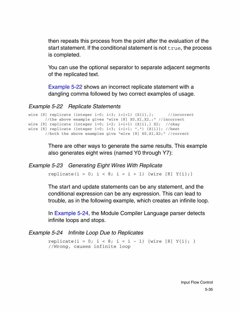
then repeats this process from the point after the evaluation of the start statement. If the conditional statement is not true, the process is completed.
You can use the optional separator to separate adjacent segments of the replicated text.
Example 5-22 shows an incorrect replicate statement with a dangling comma followed by two correct examples of usage.
Example 5-22 Replicate Statementswire [8] replicate (integer i=0; i<3; i=i+1) {X{i},}; //incorrect //the above example gives "wire [8] X0,X1,X2,;" //incorrectwire [8] replicate (integer i=0; i<2; i=i+1) {X{i},} X2; //okaywire [8] replicate (integer i=0; i<3; i=i+1; ",") {X{i}}; //best //both the above examples give "wire [8] X0,X1,X2;" //correct
There are other ways to generate the same results. This example also generates eight wires (named Y0 through Y7):
Example 5-23 Generating Eight Wires With Replicate
replicate(i = 0; i < 8; i = i + 1) {wire [8] Y{i};}
The start and update statements can be any statement, and the conditional expression can be any expression. This can lead to trouble, as in the following example, which creates an infinite loop.
In Example 5-24, the Module Compiler Language parser detects infinite loops and stops.
Example 5-24 Infinite Loop Due to Replicates
replicate(i = 0; i < 8; i = i - 1) {wire [8] Y{i}; }//Wrong, causes infinite loop
5-35
Input Flow Control

The loop variable—or any other variable—can be modified or otherwise accessed in a completely unrestricted manner inside the replicate block.
Also, in the case of replicates embedded in a statement, the entire statement is collected before it can be executed. This can lead to some subtle but potentially dangerous side effects.
In the next example, the second code fragment generates the correct result whereas the first code fragment left shifts everything by 4. Note that enclosing the integer variable inside {} causes it to be evaluated immediately and the resulting string to be placed in the input stream.
Example 5-25 replicate Examples
Z = replicate(i = 0; i < 4; i = i+1) { (X{i} << i) + } ;
//Wrong. Module Compiler generates errors
Z = replicate(i = 0; i < 4; i = i+1) {(X{i} << {i}) + } 0;
// Correct implementation of shift-and-add that generates: // Z = (X0 << 0) + (X1 << 1) + ...
Because replicate simply replicates the text block back-to-back, a problem occurs when the text blocks are separated by a “,” or an operator such as “+” as in the case above. When the loop terminates, there is a dangling “,” or “+” at the end.
You must remove the dangling “+” by padding the replicate with an expression or objects. The second code fragment in Example 5-25 shows 0 added to correct the problem.
5-36
Chapter 5: Module Compiler Language Guide
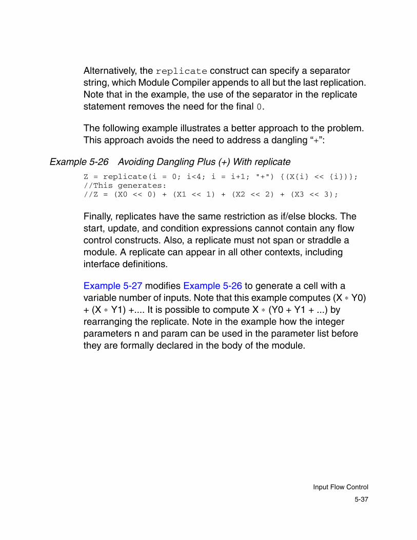
Alternatively, the replicate construct can specify a separator string, which Module Compiler appends to all but the last replication. Note that in the example, the use of the separator in the replicate statement removes the need for the final 0.
The following example illustrates a better approach to the problem. This approach avoids the need to address a dangling “+”:
Example 5-26 Avoiding Dangling Plus (+) With replicate
Z = replicate(i = 0; i<4; i = i+1; "+") {(X{i} << {i})};//This generates://Z = (X0 << 0) + (X1 << 1) + (X2 << 2) + (X3 << 3);
Finally, replicates have the same restriction as if/else blocks. The start, update, and condition expressions cannot contain any flow control constructs. Also, a replicate must not span or straddle a module. A replicate can appear in all other contexts, including interface definitions.
Example 5-27 modifies Example 5-26 to generate a cell with a variable number of inputs. Note that this example computes (X ∗ Y0) + (X ∗ Y1) +.... It is possible to compute X ∗ (Y0 + Y1 + ...) by rearranging the replicate. Note in the example how the integer parameters n and param can be used in the parameter list before they are formally declared in the body of the module.
5-37
Input Flow Control

Example 5-27 computes a multi-input sum of products as follows:
using bit-widths that are either hard-wired values or values passed in. The bit-widths need to be called as either
n =int_value, param=0
or
n = int_value, param = 1, in=int_value, out =int_value.
Example 5-27 Conditional Blocks and Replicatesmodule test ( Z, X, n, replicate(integer i=0; i<n; i=i+1;",")
{Y{i}}, param, if (param) {in, out} );//declare X and Z as before; in addition declare Y0,Y1,...,Yninteger n, param;if (param) {integer in, out;}else {integer in = 8, out = 16;}output [out - 2] Z;input [in - 2] X, replicate(i=0; i<n; i=i+1;",") {Y{i}};//generate X * Y0 + X * Y1 + X * Y2 ...Z = replicate(i=0; i<n; i=i+1; "+") {X * Y{i} } ;endmodule
A terse form of replicate is provided by the repl construct. This construct assumes that the start statement is always of the form integer i=0, the condition is always of the form i<n, and the update statement is always of the form i=i+1. You must specify the name of the iterator i and the upper limit n. You can optionally specify a separator string. In this case, the loop variable does not need to be predeclared. It is an implicitly repeated integer variable with its value initialized to 0 and with its scope local to the loop.
X Yi×i 0=
n
∑
5-38
Chapter 5: Module Compiler Language Guide
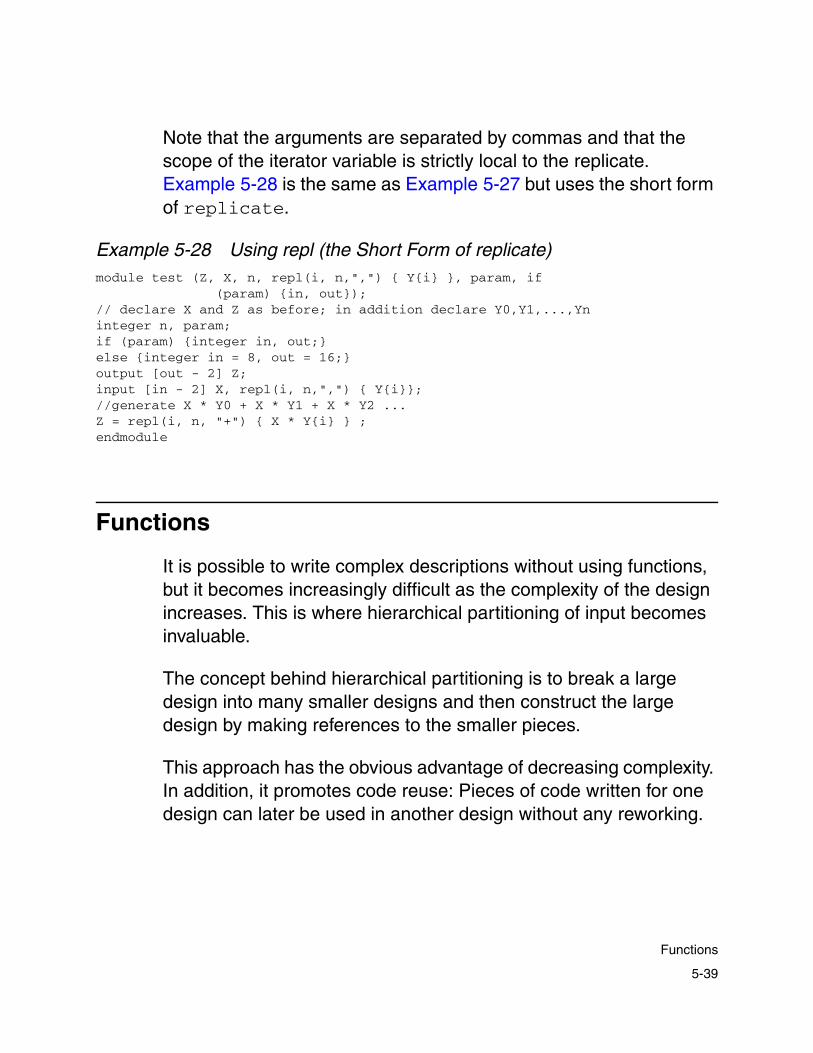
Note that the arguments are separated by commas and that the scope of the iterator variable is strictly local to the replicate. Example 5-28 is the same as Example 5-27 but uses the short form of replicate.
Example 5-28 Using repl (the Short Form of replicate)module test (Z, X, n, repl(i, n,",") { Y{i} }, param, if
(param) {in, out});// declare X and Z as before; in addition declare Y0,Y1,...,Yninteger n, param;if (param) {integer in, out;}else {integer in = 8, out = 16;}output [out - 2] Z;input [in - 2] X, repl(i, n,",") { Y{i}};//generate X * Y0 + X * Y1 + X * Y2 ...Z = repl(i, n, "+") { X * Y{i} } ;endmodule
Functions
It is possible to write complex descriptions without using functions, but it becomes increasingly difficult as the complexity of the design increases. This is where hierarchical partitioning of input becomes invaluable.
The concept behind hierarchical partitioning is to break a large design into many smaller designs and then construct the large design by making references to the smaller pieces.
This approach has the obvious advantage of decreasing complexity. In addition, it promotes code reuse: Pieces of code written for one design can later be used in another design without any reworking.
5-39
Functions

In Module Compiler Language, a function is the equivalent of a software procedure. It is a chunk of Module Compiler Language code that has been abstracted away into a named entity. You can instantiate copies of this code by referring to its name.
The code that calls this entity can itself be a similar entity. Thus, it is possible to have hierarchies of function, where you build each higher-level function by using calls to lower-level functions or building blocks. When the processing is completed, all function calls are resolved and the result is a flattened cell.
These functions are abstract entities: They are pieces of code that have no meaning outside the processing in Module Compiler. When this processing is complete, all function calls have been resolved and the result is a flat description.
A function has two aspects: the function definition (the code) and a function call (a reference to the code). In Module Compiler Language, the function definition is very similar to a module definition. A module is actually a special function that always appears at the top and cannot be called like a function.
Example 5-29 converts Example 5-27 and Example 5-28 into a function definition. It computes
by using bit-widths that are passed in.
X Yi×i 0=
n
∑
5-40
Chapter 5: Module Compiler Language Guide

Example 5-29 Bit-Widths Passed in a Function Definition
function productSum (Z, X, n, repl(i , n, ",") { Y{i}});// declare inputs and outputsinteger n;output Z;input X replicate(i = 0; i < n; i = i + 1) { Y{i},} X;//generate X * Y0 + X * Y1 + X * Y2 ...Z = replicate(i = 0; i < n; i = i + 1; "+") { X * Y{i} };
endfunction
module test (OUT, A, B, C);output [16] OUT;input [8] A, B, C;
productSum(OUT, A, 2, B, C);endmodule
In Module Compiler Language, a function can contain any statement other than a module declaration or a function declaration. The function declaration can declare new variables and can make function calls, but a function cannot be declared in a function body.
This example first replaces module and endmodule with function and endfunction and gives this function a more meaningful name, productSum. It also modifies the interface definition to exclude param, in, and out.
This is because the inputs to a function are a given: A function cannot create its own input. The function still declares its inputs, but without any attributes, which are determined by the caller.
The attributes for the output can be determined by the function, but in this case, Module Compiler leaves that up to the caller as well, so the output declaration is without attributes. This function can now be called as shown in Example 5-29.
5-41
Functions

The module test following the function productSum computes the value of OUT, using a function call that maps OUT to “Z” in productSum. It maps 2 to n, A to X, B to Y0, and so on.
A function can be written in a separate Module Compiler Language file. In other words, you can write two separate Module Compiler Language files, one for the main module calling the function and one for the function by itself. If you do this, you have to remember to include the names of both Module Compiler Language files as input files before you run your design.
User-Defined String and Integer Functions
By default, user-defined functions do not have return values, although Module Compiler supports a syntax that gives the appearance of returning a signal value.
You can create functions that return a string or an integer value by inserting the keyword string or integer, respectively, before the function. The return keyword is used to specify the return value of the function. Example 5-30 shows an integer function and a string function.
5-42
Chapter 5: Module Compiler Language Guide
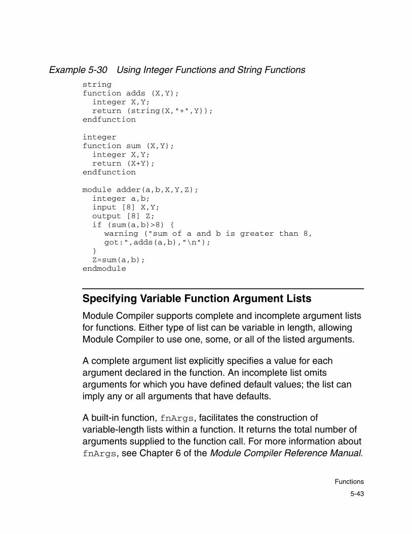
Example 5-30 Using Integer Functions and String Functions
string function adds (X,Y);
integer X,Y;return (string(X,"+",Y));
endfunction
integer function sum (X,Y);
integer X,Y;return (X+Y);
endfunction
module adder(a,b,X,Y,Z);integer a,b;
input [8] X,Y;output [8] Z;if (sum(a,b)>8) {
warning ("sum of a and b is greater than 8, got:",adds(a,b),"\n");
}Z=sum(a,b);
endmodule
Specifying Variable Function Argument Lists
Module Compiler supports complete and incomplete argument lists for functions. Either type of list can be variable in length, allowing Module Compiler to use one, some, or all of the listed arguments.
A complete argument list explicitly specifies a value for each argument declared in the function. An incomplete list omits arguments for which you have defined default values; the list can imply any or all arguments that have defaults.
A built-in function, fnArgs, facilitates the construction of variable-length lists within a function. It returns the total number of arguments supplied to the function call. For more information about fnArgs, see Chapter 6 of the Module Compiler Reference Manual.
5-43
Functions
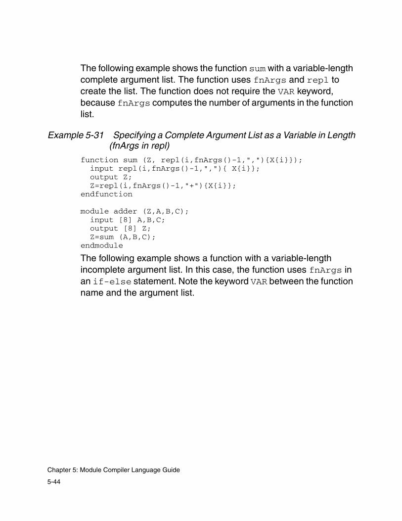
The following example shows the function sum with a variable-length complete argument list. The function uses fnArgs and repl to create the list. The function does not require the VAR keyword, because fnArgs computes the number of arguments in the function list.
Example 5-31 Specifying a Complete Argument List as a Variable in Length(fnArgs in repl)
function sum (Z, repl(i,fnArgs()-1,","){X{i}});input repl(i,fnArgs()-1,","){ X{i}};output Z;Z=repl(i,fnArgs()-1,"+"){X{i}};
endfunction
module adder (Z,A,B,C);input [8] A,B,C;output [8] Z;Z=sum (A,B,C);
endmodule
The following example shows a function with a variable-length incomplete argument list. In this case, the function uses fnArgs in an if-else statement. Note the keyword VAR between the function name and the argument list.
5-44
Chapter 5: Module Compiler Language Guide

Example 5-32 Specifying an Incomplete Argument List as a Variable in Length (if-else)
function foo VAR (Z, A, B, num);integer num=5;input A;if (fnArgs()>2) {input B;} else {wire B=~A;}output Z=A+B+num;
endfunction
module test (Z1, Z2, Z3, A, B);output [8] Z1, Z2, Z3;input [8] A,B;Z1=foo(A);// Z1=A+~A+5;Z2=foo(A,B);// Z2=A+B+5;Z3=foo(A,B,3);// Z3=A+B+3;
endmodule
The foo function in the preceding example can be called with two, three, or four arguments. By default, num has the value 5 and B is the inverse of A. If the caller supplies a value for A, B, or both, the supplied values override the defaults.
Note: If you have not specified defaults, using VAR does not solve the problem.
If the variable arguments consist only of string or integer parameters, the parser does not require you to use the VAR keyword. The parser automatically detects functions that can take a variable number of parameters.
5-45
Functions
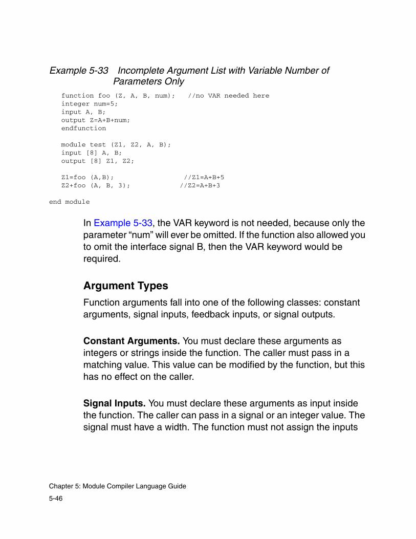
Example 5-33 Incomplete Argument List with Variable Number of Parameters Only
function foo (Z, A, B, num); //no VAR needed here integer num=5; input A, B; output Z=A+B+num; endfunction
module test (Z1, Z2, A, B); input [8] A, B; output [8] Z1, Z2;
Z1=foo (A,B); //Z1=A+B+5 Z2+foo (A, B, 3); //Z2=A+B+3
end module
In Example 5-33, the VAR keyword is not needed, because only the parameter “num” will ever be omitted. If the function also allowed you to omit the interface signal B, then the VAR keyword would be required.
Argument Types
Function arguments fall into one of the following classes: constant arguments, signal inputs, feedback inputs, or signal outputs.
Constant Arguments. You must declare these arguments as integers or strings inside the function. The caller must pass in a matching value. This value can be modified by the function, but this has no effect on the caller.
Signal Inputs. You must declare these arguments as input inside the function. The caller can pass in a signal or an integer value. The signal must have a width. The function must not assign the inputs
5-46
Chapter 5: Module Compiler Language Guide
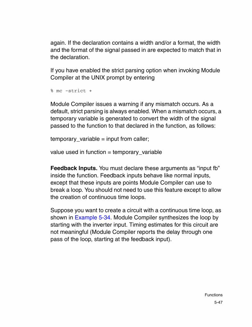
again. If the declaration contains a width and/or a format, the width and the format of the signal passed in are expected to match that in the declaration.
If you have enabled the strict parsing option when invoking Module Compiler at the UNIX prompt by entering
% mc -strict +
Module Compiler issues a warning if any mismatch occurs. As a default, strict parsing is always enabled. When a mismatch occurs, a temporary variable is generated to convert the width of the signal passed to the function to that declared in the function, as follows:
temporary_variable = input from caller;
value used in function = temporary_variable
Feedback Inputs. You must declare these arguments as “input fb” inside the function. Feedback inputs behave like normal inputs, except that these inputs are points Module Compiler can use to break a loop. You should not need to use this feature except to allow the creation of continuous time loops.
Suppose you want to create a circuit with a continuous time loop, as shown in Example 5-34. Module Compiler synthesizes the loop by starting with the inverter input. Timing estimates for this circuit are not meaningful (Module Compiler reports the delay through one pass of the loop, starting at the feedback input).
5-47
Functions

Example 5-34 Using Feedback Inputs
function delay (Z,A);input fb A;//can break loops at this inputoutput Z=~A;
endfunction
module loop (Z,A);input [1] A;output [1] Z;Z = delay(Z&A);//loop created here
endmodule
Signal Outputs. You must declare these arguments as output inside the function. The caller must pass in a signal. There are two types of functions and outputs:
• Functions that require the caller to specify the output width, such as an up-counter function that requires the caller to specify the upper limit on the counter. It is an error to call such functions with an output that does not have a width.
• Functions that do not require the caller to specify the output width and that have a good estimate of the correct output. For example, a register function knows that the output should be as wide as the input.
You can call these functions with an output that does not have a width, and the functions assign a width to the output. If you call a function by using an output whose width is different from the expected width, Module Compiler generates a temporary variable as follows:
temporary_variable = result of the function;
output from caller= temporary_variable
5-48
Chapter 5: Module Compiler Language Guide
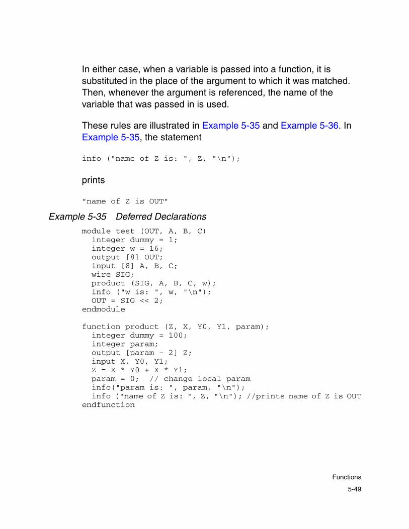
In either case, when a variable is passed into a function, it is substituted in the place of the argument to which it was matched. Then, whenever the argument is referenced, the name of the variable that was passed in is used.
These rules are illustrated in Example 5-35 and Example 5-36. In Example 5-35, the statement
info ("name of Z is: ", Z, "\n");
prints
"name of Z is OUT"
Example 5-35 Deferred Declarations
module test (OUT, A, B, C)integer dummy = 1;integer w = 16;output [8] OUT;input [8] A, B, C;wire SIG;product (SIG, A, B, C, w);info ("w is: ", w, "\n");OUT = SIG << 2;
endmodule
function product (Z, X, Y0, Y1, param);integer dummy = 100;integer param;output [param - 2] Z;input X, Y0, Y1;Z = X * Y0 + X * Y1;param = 0; // change local paraminfo("param is: ", param, "\n");info ("name of Z is: ", Z, "\n"); //prints name of Z is OUT
endfunction
5-49
Functions

• First, note that both the function and the caller have integer variables with the same name. These variables are distinct.
• Second, the integer variable that is passed to the function is modified by the function, but its value does not change in the caller.
• Third, the caller declares SIG without a width and passes it to the function as an output; the function then creates the output by assigning it the appropriate attributes.
• Fourth, the function assigns to Z, thereby assigning to SIG. The caller can now use SIG to compute something else.
Example 5-36 is a modified version of Example 5-35.
Example 5-36 Overriding Function Declarations
module test (OUT, A, B, C)integer w = 16;output [8] OUT;input [8] A, B, C;wire [8] SIG;product (SIG, 16, B, C, w);
...endmodule
function product (Z, X, Y0, Y1, param);integer param;output [param - 2] Z; input X, Y0, Y1;Z = X * Y0 + X * Y1;
endfunction
Here, note that a constant, 16, is passed in the place of X. This is allowed. Second, the caller defines SIG as an 8-bit quantity and the function defines Z as a 16-bit quantity. A temporary signal is created to convert the 16-bit Z from the function to the 8-bit SIG in the module.
5-50
Chapter 5: Module Compiler Language Guide

Declaring Variables
You must declare each variable before using it. The following example shows an error condition caused, with the parser, by using the next_sum variable before declaring it:
wire[3] sum = a + next_sum; //error: next_sum is not yet definedwire[3] next_sum = sel? wl : datain;
The following example shows the code written correctly:
wire[3] next_sum;wire[3] sum = a + sreq(next_sum);wire[3] next_sum = sel? wl : datain;
Local Variables
Because Module Compiler copies the code representing a function into the caller, the naming scheme for locally created variables—variables you create by using wire—has to allow unique names only. Usually Module Compiler creates unique names by prefixing the local variable name with the output name or the left side of the expression that called the function.
Sometimes it is also necessary to append a unique integer to the name. This name is reflected in the synthesis results as well. The naming scheme is detailed further in “Naming” on page 8-12.
Calling Conventions
Example 5-37 shows one style of calling a function. An alternative style of function call is in the form X = name(...). This style assumes that the output of the function is X.
5-51
Functions

In Example 5-37, the call to the product function can be replaced with OUT = product (A, B, C) without a change in the results. For use in this style, the function must have one or more outputs and the first parameter must be an output.
Another style of function call involves attaching an “instance name” to the function. This style takes the form
X = name instance_name(...)
or
name instance_name(...).
In either case, you use the instance name as the prefix string in naming the local variables of a function. This is useful for identifying and collecting all the signals a particular call generated to a particular function.
Functions can be embedded in expressions. In such a case, Module Compiler implicitly creates the output of the function as a temporary variable. In order for this to work correctly, you must declare the width of the output inside the function.
5-52
Chapter 5: Module Compiler Language Guide

Example 5-37 Function-Calling Conventions
module test (OUT, A, B, C)integer w = 8;output [8] OUT;input [8] A, B, C;wire U, V, W;product(U, A, B, C, w);// virtually identical to the call aboveV = product (A, B, C, w);// use an instance name. 'temp' in the// function call will be named // call1_tempproduct call1 (W, A, B, C, w);
endmodule
function product (Z, X, Y0, Y1, param);integer param;
output [param - 2] Z; input X, Y0, Y1;wire [8] temp;temp = Y0 + Y1;Z = X * temp;info ("name of Z is: ", Z, "\n") ; info ("name of temp is: ", temp, "\n");
endfunction
Built-in Functions
Module Compiler comes with a set of built-in integer and string functions, which should not be redefined. The width function is an example of a built-in function. It accepts a signal and returns its width. Another example of a built-in function is formatStr, which returns the format of a signed or unsigned string, depending on the format of the signal passed in. The comprehensive set of built-in functions is covered in the Module Compiler Reference Manual.
5-53
Built-in Functions

Module Compiler also includes a library of signal functions, which are defined in a library file. These functions implement primitives that are not representable with operators. You can redefine a library function, although the practice is not recommended.
Table 5-7 lists some library functions.
For more information about library functions, see the Module Compiler Reference Manual.
Messages
Module Compiler Language provides several functions for printing messages during the input compilation stage. These functions are useful in catching and reporting errors and as a general debugging aid. The following types of messages are available: information, warning, error, and fatal error messages.
Table 5-7 Examples of Library Functions
Function Action
cat Concatenates bits of different signals to create a new signal
sat Clips the outputs to given values
sreg Creates a state register
5-54
Chapter 5: Module Compiler Language Guide

Information Message
The syntax for the info function is very similar to that of the string function. The info function concatenates all its inputs and prints them in the standard output. It is a general debugging aid. The info function has no effect on subsequent processing. Some examples of info messages are shown in Example 5-38.
Example 5-38 Using the info Keyword
integer n = 16;...wire [n - 2] X;info ("name of X is ", X, " and width is: ", width(X), "\n");//prints out "name of X is X and width is: 16"
info("n exceeds magic value: ", n > magic, "\n");//if n > magic, prints out "n exceeds magic value: 1" //else prints out "n exceeds magic value: 0"
There is usually a leading identifier in the output to indicate that this message was generated as a result of an info statement. The name of the file and the function containing the statement are also printed. Such messages, when combined with macros and conditional (if/else) constructs, provide a useful tool for debugging complex Module Compiler inputs. Macros and flow control (if/else) are described earlier in this chapter.
Warning Message
This message is on the info message. Here the occurrence is counted as a warning; therefore, warning allows processing to continue but prints warning messages that appear at the end of the GUI status window. The parser and the synthesizer try to continue. The keyword for warning messages is warning.
5-55
Messages

Error Message
This message is virtually identical to the info message, except that its occurrence is counted as an error. When the Module Compiler Language parser encounters this message, it tries to continue but no synthesis takes place. If the parser encounters many of these messages, it quits. The keyword for error messages is error.
Example 5-39 Using the error Message
error("n exceeds magic value! n = ", n, "magic = , magic, "\n");
In this example, Module Compiler prints the error message
"n exceeds magic value! n = 10, magic = 5"
if n and magic are 10 and 5, respectively.
Fatal Error Message
This message is a stricter form of error. When the Module Compiler Language parser encounters this statement, it prints the message and immediately quits all processing. In other words, fatal immediately suspends all parsing.
Example 5-40 Using the fatal Message
fatal ("integer divide by zero! m-n equal 0 in (x/( m - n))\n");
In Example 5-40, Module Compiler prints the error message
"integer divide by zero! m-n equal 0 in (x/(m - n))"
and quits.
5-56
Chapter 5: Module Compiler Language Guide
Note: The Module Compiler Language parser processes the input in two passes. All user-created messages are processed in the first pass, and the final checks for consistently declared and defined signals take place in the second pass. Consequently, the illusion is possible that the Module Compiler Language parser might seem to be generating error messages that are not properly synchronized with the user-created messages.
5-57
Messages

5-58
Chapter 5: Module Compiler Language Guide

6Module Compiler Language Usage 6
This chapter is a guide for using Module Compiler Language. You learn how a particular construct and how it is used affect the synthesized result. This chapter has the following sections:
• Module Compiler Language Details
• Function Library
• Asynchronous Set-Reset Flip-Flop Support
• Assignment Operator (=)
• Operators and Functions Based on Addition
• Logical, Reduction, Shift, and MUX Operators
• Format Conversion Circuits
• Sequential Circuits
6-1
• State Registers
• Scan Cells
• Demultiplexing
• Black Box Support
• Signal Manipulation Functions
• Module Compiler Generic Cell Library
• Technology-Specific Cells
• Using Groups in Complex Designs
• Report Control
• Creating a Video Processor
• Optimizing Performance and Area
6-2
Chapter 6: Module Compiler Language Usage

Module Compiler Language Details
This section is an overview of the basic parts of the Module Compiler Language. In this chapter, you learn how a particular construct and the way it is used affect the synthesized result.
Unlike other high-level design languages, Module Compiler Language not only describes the functionality of the circuit but also contains directives that control how the circuit is synthesized and optimized.
This section describes the various constructs available in Module Compiler Language and the effect they have on the circuit being synthesized. In this section, you learn about module naming, I/O constraints, module parameters, and constants. Then you learn about integer variables, operands, and temporary operands.
Module Definition
The module construct specifies the default design name and the interface signals for the design to be generated by Module Compiler.
Module Naming
By default, Module Compiler uses the module name as the root name of all output files that are unique to the design.
You can change the module name by using the modname attribute, as shown in Example 6-1. This is particularly useful for preventing name collisions when you are constructing many modules from the same description. In addition, changing the module name is useful for preserving output files during iteration through design parameters during a parametric synthesis run.
6-3
Module Compiler Language Details

You can pass the module name in as a parameter, or the name can be generated internally to the module, with the existing set of parameters.
Example 6-1 Using modname to Change the Module Name
module dummy (X,Y,Z,a);input [8] X,Y;output [8] Z;integer a;directive (modname=string("goober_",a));//change the module name//...
endmodule
Signal Interface
The naming and ordering of the signals in the module signal interface definition is preserved in the simulation model and netlists Module Compiler generates.
I/O Constraints
External loading and timing constraints for inputs and outputs of a module are specified by use of directives. All load values have units of 0.1 standard load, and delays have units of picoseconds.
The maximum loading allowed at an input is indicated by the inload attribute. Module Compiler does not put more than this load value on the inputs.
You use indelay to specify the arrival time of the input. If indelay is positive, it indicates an input arriving later than the default (0), making paths from that input more critical. Any negative values are treated as minus infinity, making paths from that point noncritical.
6-4
Chapter 6: Module Compiler Language Usage
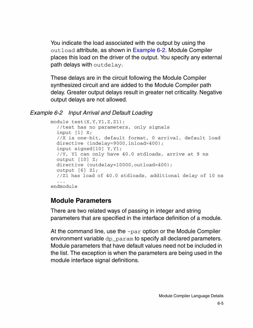
You indicate the load associated with the output by using the outload attribute, as shown in Example 6-2. Module Compiler places this load on the driver of the output. You specify any external path delays with outdelay.
These delays are in the circuit following the Module Compiler synthesized circuit and are added to the Module Compiler path delay. Greater output delays result in greater net criticality. Negative output delays are not allowed.
Example 6-2 Input Arrival and Default Loading
module test(X,Y,Y1,Z,Z1);//test has no parameters, only signalsinput [1] X; //X is one-bit, default format, 0 arrival, default load directive (indelay=9000,inload=400);input signed[10] Y,Y1; //Y, Y1 can only have 40.0 stdloads, arrive at 9 nsoutput [10] Z;directive (outdelay=10000,outload=400);output [6] Z1;//Z1 has load of 40.0 stdloads, additional delay of 10 ns...
endmodule
Module Parameters
There are two related ways of passing in integer and string parameters that are specified in the interface definition of a module.
At the command line, use the -par option or the Module Compiler environment variable dp_param to specify all declared parameters. Module parameters that have default values need not be included in the list. The exception is when the parameters are being used in the module interface signal definitions.
6-5
Module Compiler Language Details

In the following example, n and w are module parameters. Because the parameter n defines the signals in the module signal list, you must always specify it with the -par option. Even if you assign n a default value, the default value cannot be used. The parameter w is optional and defaults to a value of 8 if you do not give it a value.
module adder (Z,n,repl(i,n,",") {A{i}},w);
integer n; //number of addendsinteger w = 8; //width of addends
input signed [w] repl(i,n,",") {A{i}};
output [w] repl(i,n,"+") {A{i}};
endmodule
The general form uses comma-separated parameter name and value pairs, without space separators, as shown below:
-par par=val[,par=val*]
In the GUI, place the information in the Parameters field of the main window. Because both interfaces use the same syntax, parameters set in either interface carry over to the other.
Note: No spaces are allowed anywhere in the parameter list.
Module Compiler automatically determines the type of each parameter. Any parameter that does not appear to be a number is passed as a string, and any parameter that is a number is passed as an integer. This means that you cannot use numbers as a value of a string parameter.
6-6
Chapter 6: Module Compiler Language Usage
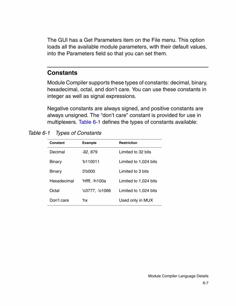
The GUI has a Get Parameters item on the File menu. This option loads all the available module parameters, with their default values, into the Parameters field so that you can set them.
Constants
Module Compiler supports these types of constants: decimal, binary, hexadecimal, octal, and don’t care. You can use these constants in integer as well as signal expressions.
Negative constants are always signed, and positive constants are always unsigned. The “don’t care” constant is provided for use in multiplexers. Table 6-1 defines the types of constants available:
Table 6-1 Types of Constants
Constant Example Restriction
Decimal −32, 879 Limited to 32 bits
Binary 'b110011 Limited to 1,024 bits
Binary 3’b000 Limited to 3 bits
Hexadecimal 'hffff, −'h100a Limited to 1,024 bits
Octal 'o3777, −'o1066 Limited to 1,024 bits
Don’t care 'hx Used only in MUX
6-7
Module Compiler Language Details

Integer Variables
Integer expressions are resolved at Module Compiler runtime and do not cause hardware to be built. They are used to parameterize and control the replication of objects that result in hardware.
Mixed integer and signal expressions do result in the construction of hardware. The value of the integer portion of the expression is a constant in the hardware.
Operands
An operand is a variable that participates in an operator expression. In the context of Module Compiler, an operand is a signal variable or a signal constant. All operands have signed or unsigned formats, and you can choose any range of bits as the input to a function.
You can declare the format of signals explicitly; the default format is unsigned. For all operands, the most significant bit (MSB) is always the highest-numbered bit. Bit numbers always start from 0. If any bit range includes the MSB of a signed operand, it is also signed; otherwise, it is unsigned.
If X is a 10-bit signed number, the following bit ranges are signed:
Example 6-3 Signed Bit Ranges
XX[9:0]X[9]X[9:5]
6-8
Chapter 6: Module Compiler Language Usage

The following bit ranges are unsigned:
Example 6-4 Unsigned Bit Ranges
X[8:0]X[4:3]X[0]
You should choose the format of input and wires carefully, because many functions and operators use the formats of the operands to determine the synthesized structure.
For example, a multiplier is synthesized differently if the inputs are signed rather than unsigned. This should be clear, because for 4-bit numbers, 1111∗1111 = 11100001 (225) and 00000001 (1) if the inputs are unsigned and signed, respectively.
Note that the use of [ ] to indicate a bit range is different when an operand is being used than when an operand is being declared. If no range is specified when an operand is used, the entire operand is used.
If you do not specify a range when you declare an operand, the operand is created with an undefined width and the width is determined later. Similarly, X[0] means the 0 bit of X. To declare an operand with only 1 bit, use X[1] or X[0:0].
Note: Normally, bit ranges are not allowed on the left side of an expression. However, you can enable the use of bit ranges on the left side by setting dp_bit_range_lhs to + in the mc.env file.
6-9
Module Compiler Language Details

Function Library
Module Compiler Language supports a rich set of signal operators. However, the signal operators alone are insufficient to describe many designs. For example, there is no operator notation to describe a register.
Module Compiler provides additional functionality in a library of functions. Some of these functions are synthesis primitives, and Module Compiler builds others by using these primitives. The following sections provide some direction about the interpretation and use of a selected set of these functions. The definitive source of usage information is the Module Compiler Reference Manual.
The library of Module Compiler functions has grown and will continue to grow over time. The library functions that represent synthesized hardware are summarized in Table 6-2.
Table 6-2 Signal Library Functions
Function Description
accum (output Z, input X, input R, input S) Accumulator
AccPM (output Z, input C, input X, input Y, input ADD, input XS, input YS);
Z=C +/- X*Y
alup (output Z, input A, input B, input DI, output DO, input CI, input INST, output FLAGS, input FirstCyc, integer inst Mask);
Programmable 16-instruction ALU
bitrev (output out, input in); Reverses bits (MSB <-> LSB)
buffer (output out, integer depth); Sets buffer depth for operand
cat (output Z, input D0, ... , input Dn) Concatenates
6-10
Chapter 6: Module Compiler Language Usage
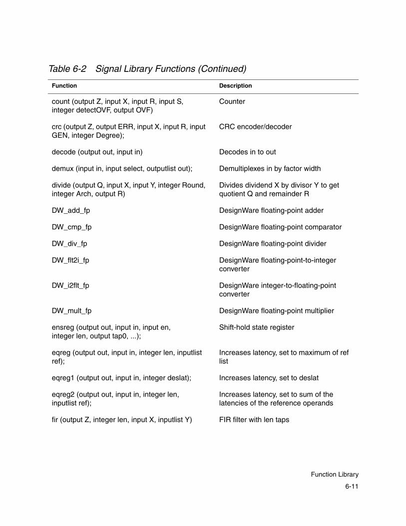
count (output Z, input X, input R, input S, integer detectOVF, output OVF)
Counter
crc (output Z, output ERR, input X, input R, input GEN, integer Degree);
CRC encoder/decoder
decode (output out, input in) Decodes in to out
demux (input in, input select, outputlist out); Demultiplexes in by factor width
divide (output Q, input X, input Y, integer Round, integer Arch, output R)
Divides dividend X by divisor Y to get quotient Q and remainder R
DW_add_fp DesignWare floating-point adder
DW_cmp_fp DesignWare floating-point comparator
DW_div_fp DesignWare floating-point divider
DW_flt2i_fp DesignWare floating-point-to-integer converter
DW_i2flt_fp DesignWare integer-to-floating-point converter
DW_mult_fp DesignWare floating-point multiplier
ensreg (output out, input in, input en,integer len, output tap0, ...);
Shift-hold state register
eqreg (output out, input in, integer len, inputlist ref);
Increases latency, set to maximum of ref list
eqreg1 (output out, input in, integer deslat); Increases latency, set to deslat
eqreg2 (output out, input in, integer len, inputlist ref);
Increases latency, set to sum of the latencies of the reference operands
fir (output Z, integer len, input X, inputlist Y) FIR filter with len taps
Table 6-2 Signal Library Functions (Continued)
Function Description
6-11
Function Library
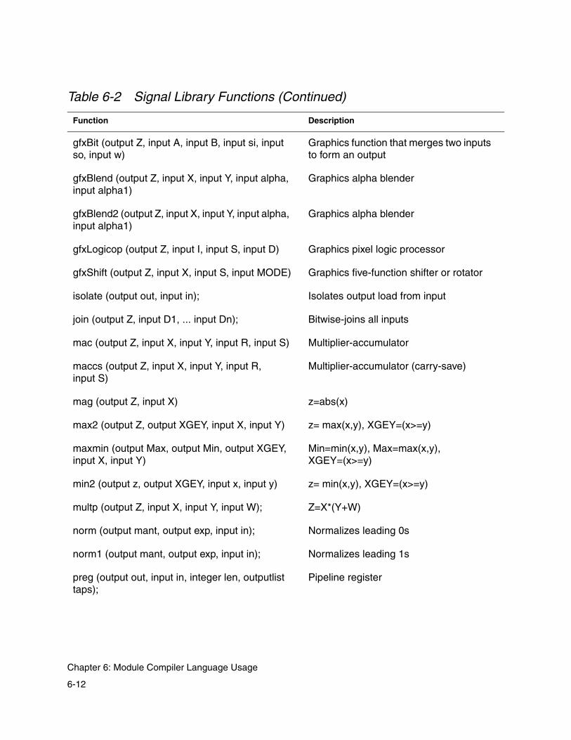
gfxBit (output Z, input A, input B, input si, input so, input w)
Graphics function that merges two inputs to form an output
gfxBlend (output Z, input X, input Y, input alpha, input alpha1)
Graphics alpha blender
gfxBlend2 (output Z, input X, input Y, input alpha, input alpha1)
Graphics alpha blender
gfxLogicop (output Z, input I, input S, input D) Graphics pixel logic processor
gfxShift (output Z, input X, input S, input MODE) Graphics five-function shifter or rotator
isolate (output out, input in); Isolates output load from input
join (output Z, input D1, ... input Dn); Bitwise-joins all inputs
mac (output Z, input X, input Y, input R, input S) Multiplier-accumulator
maccs (output Z, input X, input Y, input R, input S)
Multiplier-accumulator (carry-save)
mag (output Z, input X) z=abs(x)
max2 (output Z, output XGEY, input X, input Y) z= max(x,y), XGEY=(x>=y)
maxmin (output Max, output Min, output XGEY, input X, input Y)
Min=min(x,y), Max=max(x,y), XGEY=(x>=y)
min2 (output z, output XGEY, input x, input y) z= min(x,y), XGEY=(x>=y)
multp (output Z, input X, input Y, input W); Z=X*(Y+W)
norm (output mant, output exp, input in); Normalizes leading 0s
norm1 (output mant, output exp, input in); Normalizes leading 1s
preg (output out, input in, integer len, outputlist taps);
Pipeline register
Table 6-2 Signal Library Functions (Continued)
Function Description
6-12
Chapter 6: Module Compiler Language Usage
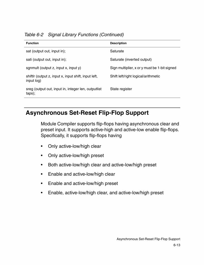
Asynchronous Set-Reset Flip-Flop Support
Module Compiler supports flip-flops having asynchronous clear and preset input. It supports active-high and active-low enable flip-flops. Specifically, it supports flip-flops having
• Only active-low/high clear
• Only active-low/high preset
• Both active-low/high clear and active-low/high preset
• Enable and active-low/high clear
• Enable and active-low/high preset
• Enable, active-low/high clear, and active-low/high preset
sat (output out, input in); Saturate
sati (output out, input in); Saturate (inverted output)
sgnmult (output z, input x, input y) Sign multiplier, x or y must be 1-bit signed
shiftlr (output z, input x, input shift, input left, input log)
Shift left/right logical/arithmetic
sreg (output out, input in, integer len, outputlist taps);
State register
Table 6-2 Signal Library Functions (Continued)
Function Description
6-13
Asynchronous Set-Reset Flip-Flop Support

async_preset and async_clear
Module Compiler supports use of asynchronous clear and preset inputs, using the attributes async_preset and async_clear, which are described below.
The async_preset attribute specifies the signal connected to the preset input of the flip-flop. This attribute can take one of the following string values:
• async_preset = "signal_connected_to_preset"
Sets the signal specified by the string value to the preset pin.
• async_preset = ""
Sets no signal to preset input.
The async_clear attribute specifies the signal connected to the clear input of the flip-flop. This attribute can take one of the following string values:
• async_clear = "signal_connected_to_clear"
Sets the signal specified by the string value to the clear pin.
• async_clear = ""
Sets no signal to clear input.
The default value for async_preset and async_clear is " ", or no signal connected.
6-14
Chapter 6: Module Compiler Language Usage

Using Flip-Flops With Active-High Clear and/or Preset
If your library has flip-flops with active-high clear or active-high preset, you can use them in your design by setting the Module Compiler environment variable dp_asyncFF_active_high. The default value of this variable is “-” (minus), which indicates that Module Compiler uses flip-flops having active-low clear and active-low preset.
To use flip-flops with active-high clear and active-high preset, you set this variable to “+” (plus) by entering at the UNIX prompt
% mcenv dp_asyncFF_active_high +
If you have used the async_clear and/or async_preset directives, Module Compiler will use active-high clear and active-high preset flip-flops in your design, once dp_asyncFF_active_high is set to “+”.
If you do not have active-high clear and active-high preset flip-flops in your library and have set dp_asyncFF_active_high to “+”, Module Compiler will display an “L9” error message to alert you that the flip-flop cells are missing.
Signals Connected to Clear and Preset
The signal connected to clear or preset input of the flip-flop must be an input signal. It cannot be a wire. The signal connected to clear or preset can be either a signal that has been explicitly declared as an input or a signal specified as a string in the directive statement where async_clear or async_preset get their signal values. Module Compiler treats a signal specified as a string as an input.
6-15
Asynchronous Set-Reset Flip-Flop Support
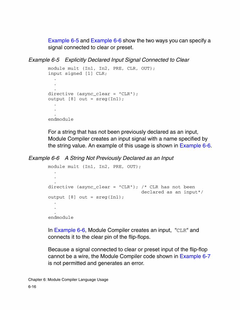
Example 6-5 and Example 6-6 show the two ways you can specify a signal connected to clear or preset.
Example 6-5 Explicitly Declared Input Signal Connected to Clear
module mult (In1, In2, PRE, CLR, OUT);input signed [1] CLR; . . .directive (async_clear = "CLR"); output [8] out = sreg(In1); . . .endmodule
For a string that has not been previously declared as an input, Module Compiler creates an input signal with a name specified by the string value. An example of this usage is shown in Example 6-6.
Example 6-6 A String Not Previously Declared as an Input
module mult (In1, In2, PRE, OUT); . . .directive (async_clear = "CLR"); /* CLR has not been
declared as an input*/output [8] out = sreg(In1); . . .endmodule
In Example 6-6, Module Compiler creates an input, “CLR“ and connects it to the clear pin of the flip-flops.
Because a signal connected to clear or preset input of the flip-flop cannot be a wire, the Module Compiler code shown in Example 6-7 is not permitted and generates an error.
6-16
Chapter 6: Module Compiler Language Usage
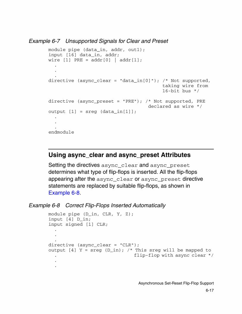
Example 6-7 Unsupported Signals for Clear and Preset
module pipe (data_in, addr, out1);input [16] data_in, addr;wire [1] PRE = addr[0] | addr[1]; . . .directive (async_clear = "data_in[0]"); /* Not supported,
taking wire from16-bit bus */
directive (async_preset = "PRE"); /* Not supported, PREdeclared as wire */
output [1] = sreg (data_in[1]];.
. .endmodule
Using async_clear and async_preset Attributes
Setting the directives async_clear and async_preset determines what type of flip-flops is inserted. All the flip-flops appearing after the async_clear or async_preset directive statements are replaced by suitable flip-flops, as shown in Example 6-8.
Example 6-8 Correct Flip-Flops Inserted Automatically
module pipe (D_in, CLR, Y, Z);input [4] D_in;input signed [1] CLR; . . .directive (async_clear = "CLR"); output [4] Y = sreg (D_in); /* This sreg will be mapped to
. flip-flop with async clear */
. .
6-17
Asynchronous Set-Reset Flip-Flop Support
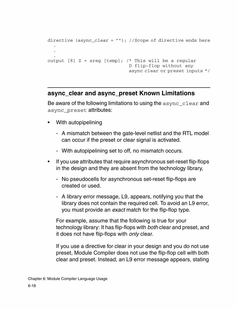
directive (async_clear = ""); //Scope of directive ends here . . .output [8] Z = sreg [temp]; /* This will be a regular
D flip-flop without anyasync clear or preset inputs */
async_clear and async_preset Known Limitations
Be aware of the following limitations to using the async_clear and async_preset attributes:
• With autopipelining
- A mismatch between the gate-level netlist and the RTL model can occur if the preset or clear signal is activated.
- With autopipelining set to off, no mismatch occurs.
• If you use attributes that require asynchronous set-reset flip-flops in the design and they are absent from the technology library,
- No pseudocells for asynchronous set-reset flip-flops are created or used.
- A library error message, L9, appears, notifying you that the library does not contain the required cell. To avoid an L9 error, you must provide an exact match for the flip-flop type.
For example, assume that the following is true for your technology library: It has flip-flops with both clear and preset, and it does not have flip-flops with only clear.
If you use a directive for clear in your design and you do not use preset, Module Compiler does not use the flip-flop cell with both clear and preset. Instead, an L9 error message appears, stating
6-18
Chapter 6: Module Compiler Language Usage

that the required cell is missing from the technology library. This error occurs because an exact match for the flip-flop type is not present.
• Every time the value of the async_preset or async_clear attribute changes, the group has to be changed—a single group cannot have more than one value for the async_preset or async_clear attribute. Examples of this limitation follow, from Example 6-9 to Example 6-13 on page 6-23.
Module Compiler generates a SYN79C error message for Module Compiler Language in Example 6-9.
• You cannot use active-high clear and active-high preset flip-flops in a design having active-low clear and active-low preset flip-flops. This limitation is because once the Module Compiler environment variable dp_asyncFF_active_high is set to “+”, Module Compiler uses only flip-flops having active-high clear and active-high preset. Currently, no directive permits you to control the usage of active-high or -low flip-flops from the Module Compiler Language code.
Example 6-9 Code That Gives a SYN79C Error
module test1 (a,b,w,X,Y,Z,PRE1,CLR1,PRE2,CLR2);integer w=4;input signed [1] PRE1,CLR1,PRE2,CLR2;input [w] a,b;directive (group="g1", async_preset = "PRE1", async_clear = "CLR1");wire [2*w] mult = a*b;output [2*w] X = sreg(mult); /* maps to FF having both
clear and preset */directive (group = "g2", async_clear = "CLR2", async_preset = ""); // scope of async_preset ends herewire [w+1] add = a+b;output [w+1] Y = sreg(add,2); /* maps to FF with only clear, preset is "" */wire [2*w] addmult = add + mult;directive (async_preset = "PRE2"); /*preset is being set
6-19
Asynchronous Set-Reset Flip-Flop Support
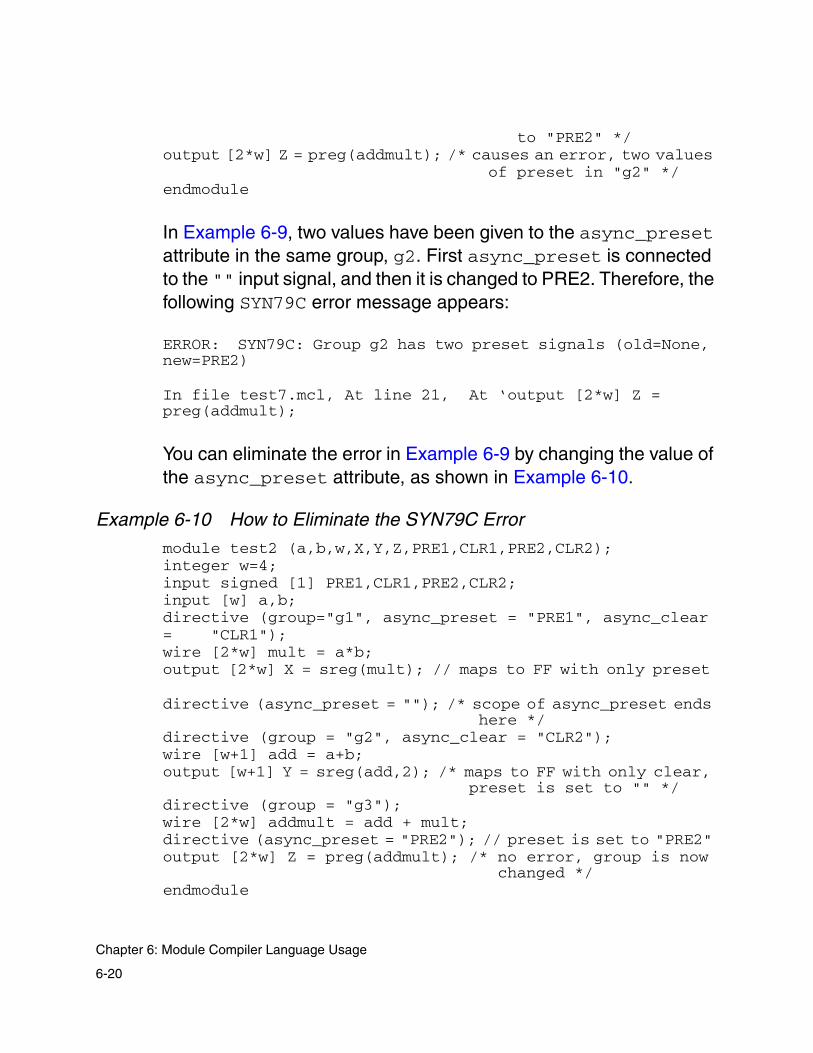
to "PRE2" */output [2*w] Z = preg(addmult); /* causes an error, two values
of preset in "g2" */endmodule
In Example 6-9, two values have been given to the async_preset attribute in the same group, g2. First async_preset is connected to the "" input signal, and then it is changed to PRE2. Therefore, the following SYN79C error message appears:
ERROR: SYN79C: Group g2 has two preset signals (old=None, new=PRE2)
In file test7.mcl, At line 21, At ‘output [2*w] Z = preg(addmult);
You can eliminate the error in Example 6-9 by changing the value of the async_preset attribute, as shown in Example 6-10.
Example 6-10 How to Eliminate the SYN79C Error
module test2 (a,b,w,X,Y,Z,PRE1,CLR1,PRE2,CLR2);integer w=4;input signed [1] PRE1,CLR1,PRE2,CLR2;input [w] a,b;directive (group="g1", async_preset = "PRE1", async_clear = "CLR1");wire [2*w] mult = a*b;output [2*w] X = sreg(mult); // maps to FF with only preset
directive (async_preset = ""); /* scope of async_preset ends here */
directive (group = "g2", async_clear = "CLR2");wire [w+1] add = a+b;output [w+1] Y = sreg(add,2); /* maps to FF with only clear,
preset is set to "" */directive (group = "g3"); wire [2*w] addmult = add + mult;directive (async_preset = "PRE2"); // preset is set to "PRE2" output [2*w] Z = preg(addmult); /* no error, group is now
changed */endmodule
6-20
Chapter 6: Module Compiler Language Usage

Example 6-11 Code That Gives No SYN79C Error
module test3 (a,b,w,X,Y,Z,PRE1,CLR1,PRE2,CLR2);integer w=4;input signed [1] PRE1,CLR1,PRE2,CLR2;input [w] a,b;directive (group="g1", async_preset = "PRE1", async_clear =
"CLR1");wire [2*w] mult = a*b;output [2*w] X = sreg(mult); // * maps to FF with only preset directive (async_preset = ""); /* scope of async_preset ends
here */directive (group = "g2", async_clear = "CLR2");wire [w+1] add = a+b;output [w+1] Y = sreg(add,2); //maps to FF with only clear,
preset is set to "" */directive (group = "g3"); wire [2*w] addmult = add + mult;directive (async_preset = "PRE2"); // preset is set to "PRE2" output [2*w] Z = preg(addmult); /* no error, group is now
changed */directive (async_preset = ""); endmodule
In Example 6-11, group g3 has two values for the async_preset attribute: First the attribute is set to PRE2, and then it is changed to "". Nevertheless, no error occurs, because no flip-flop is being used after the change in the attribute value from PRE2 to "". Only if the change in the attribute is succeeded by the use of a flip-flop in the design does the SYN79C error occur.
Example 6-12 is another Module Compiler code sample where the SYN79C error appears.
Example 6-12 Another SYN79C Error Example
module test4 (a,b,w,X,Y,Z,PRE,CLR);integer w=4;input signed [1] PRE,CLR;input signed [w] a,b;
6-21
Asynchronous Set-Reset Flip-Flop Support
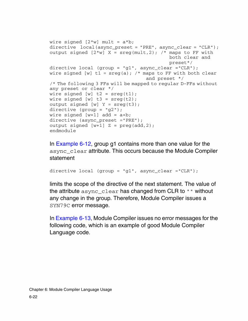
wire signed [2*w] mult = a*b;directive local(async_preset = "PRE", async_clear = "CLR");output signed [2*w] X = sreg(mult,2); /* maps to FF with
both clear andpreset*/
directive local (group = "g1", async_clear ="CLR");wire signed [w] t1 = sreg(a); /* maps to FF with both clear
and preset *//* The following 3 FFs will be mapped to regular D-FFs without any preset or clear */wire signed [w] t2 = sreg(t1); wire signed [w] t3 = sreg(t2);output signed [w] Y = sreg(t3); directive (group = "g2");wire signed [w+1] add = a+b;directive (async_preset ="PRE");output signed [w+1] Z = preg(add,2);endmodule
In Example 6-12, group g1 contains more than one value for the async_clear attribute. This occurs because the Module Compiler statement
directive local (group = "g1", async_clear ="CLR");
limits the scope of the directive of the next statement. The value of the attribute async_clear has changed from CLR to "" without any change in the group. Therefore, Module Compiler issues a SYN79C error message.
In Example 6-13, Module Compiler issues no error messages for the following code, which is an example of good Module Compiler Language code.
6-22
Chapter 6: Module Compiler Language Usage

Example 6-13 Correct Use of async_preset and async_clear
module test5 (a,b,w,X,Y,Z,PRE,CLR);integer w=4;input signed [1] PRE,CLR;input [w] a,b;directive (group="g1", async_clear = "CLR");wire [2*w] mult = a * b;output [2*w] X = sreg(mult); //maps to FF with only cleardirective (group = "g2", async_preset = "PRE", async_clear
= "");wire [w+1] add = b+a;output [w+1] Y = sreg(add,2); //maps to FF with only presetwire [2*w] addmult = add + mult;output [2*w] Z = sreg(addmult); //maps to FF with only presetendmodule
Example 6-13 has two references to sreg in group g2. This example demonstrates that you can have more than one reference to sreg, preg, or ensreg in a single group as long as the signals connected to async_clear do not change throughout the group. The only requirement is that all instances of sreg, preg, or ensreg in the same group have the same signal connected to their clear inputs and the same signal connected to their preset inputs.
Assignment Operator (=)
You can use assignments in two ways:
• You can assign the result of some operation to an operand.
• You can assign one operand to another operand.
The second form of assignment is used to simply copy bits from the source operand to the destination. All bits from the source that fall within the bit range of the destination are copied to the bit having the same value.
6-23
Assignment Operator (=)

Bits from the source that fall outside the bit range of the destination are discarded. Signed sources are sign-extended when assigned to a wider destination. Unsigned sources are zero-extended under the same condition.
The format of the destination does not affect the operation. In fact, assignment is a convenient way to perform format conversion.
Assignment does not check for overflow and truncation, potentially allowing large errors. You should use the sat function in circumstances in which you want to map the source into the nearest legal value of the destination.
Pure assignment always converts a carry-save signal to binary, regardless of the setting of the carrysave attribute. To copy a carry-save operand, use the + operator. See Example 6-14 for information about the carrysave attribute.
Example 6-14 Example of carrysave Usage
module mult32 (Z,X,Y);input [32] X;input [32] Y;output [64] Z;// no final adders for Z0,Z1,Z2,Z3
directive(carrysave="on"); wire [1] Z0,Z1,Z2,Z3;Z0=Y[8]*X;Z1=Y[15:8]*X;Z2=Y[23:16]*X;Z3=Y[31:24]*X;
directive(carrysave="off");Z=Z0+(Z1<<8)+(Z2<<16)+(Z3<<24); //Z must have final adder
endmodule
6-24
Chapter 6: Module Compiler Language Usage
Operators and Functions Based on Addition
The addition operators and functions are the most complex and versatile of all the Module Compiler functions. They are used to implement any function requiring general addition, including subtraction, multiplication, incrementing, magnitude comparison, and any combination of these operations.
The sum is implemented in three distinct steps:
• The generation of addends
• The Wallace tree reduction of the addends to a carry-save value (two signals per bit position)
• The final carry-propagate addition that reduces the carry-save value to a true binary (one signal per bit position) result
Due to the complexity of the subject, most of the synthesis details of sum are discussed later, in “Arithmetic Computation” on page 9-3. Example 6-15 illustrates expressions using addition in Module Compiler Language.
6-25
Operators and Functions Based on Addition

Example 6-15 Examples of Expressions That Use Addition
X=A+B;
X=A-(B[6:1]<<3);
directive(multtype="booth");X=A*B; //uses a booth multiplier
directive(multtype="nonbooth");X2=A[7:4]*(B[4]<<2); //uses a non-Booth multiplierX3=-A[7:4]*(B[4]<<2); //uses a non-Booth multiplier
directive(round=4);X=A+B;
directive(fatype="clsa", fadelay=4000); //4.0 ns clsa adder Z=X+Y;
directive (fatype="csa"); //csa, default delay goalZ=X+Y;
directive (fatype="fastcla"); //use fastclaZ=X+Y;
directive (fatype="fastcla");X=A*B+C*(D<<2)+E*F-(G[9]<<1)+H*I[7]+K+L;
Synthesis Attributes Affecting Addition Operators
Table 6-3 shows several attributes that affect the synthesis of these functions.
Table 6-3 Synthesis Attributes Affecting Addition Operators
Synthesisattribute
Description Value
archopt ripple adder optimization goal auto, speed, size, none
archtype ripple architecture type auto, inverting, noninverting
6-26
Chapter 6: Module Compiler Language Usage

You can use the maxtreedepth synthesis attribute to limit the depth of the Wallace tree used to implement these functions. Depending on your design, as the value of maxtreedepth decreases, the implementation can become more serial and slower.
As expected, the serial structures are slower than the parallel structures. The areas of the serial and the parallel structures are often similar. However, after place and route, you would expect the serial structures to have a higher utilization than the parallel ones.
For most structures, this attribute should not need changing. If you observe poor utilization, try reducing maxtreedepth. The minimum Wallace tree depth allowed is 3.
fatype Final adder type aofcla, auto, cla, clsa, csa, fastcla, ripple, ripple_alt
fadelay Final adder delay goal, in ps Only for csa and clsa types
multtype Multiplier type auto, booth, nonbooth
maxtreedepth Maximum Wallace tree depth 3=>serial, large value =>parallel
dirext Force direct sign extension on, off
carrysave Carry-save mode on, off, convert, optimize
round Round result to given position Integer values
intround Internally round arithmetic operations
Integer values
Table 6-3 Synthesis Attributes Affecting Addition Operators (Continued)
Synthesisattribute
Description Value
6-27
Operators and Functions Based on Addition

You can bypass the final addition to achieve area and performance improvements, by setting the carrysave synthesis attribute. This is further described in “Carry-Save” on page 6-29 and in “Carry-Save Operands” on page 9-29.
To use direct sign extension, set the dirext synthesis attribute to on. To round the result to the nth bit, where bit n is the new least significant bit (LSB), use the round synthesis attribute. Do not use the round attribute with accumulator (recursive) structures.
You specify the multiplier architecture by using the multtype synthesis attribute. When multtype is set to auto, the Booth architecture is employed if the X and Y inputs have at least 16 bits combined; otherwise, non-Booth architecture is used. The relative advantages of Booth and non-Booth architectures are discussed in “Multiplication” on page 9-8 and in the Module Compiler Reference Manual.
The fatype synthesis attribute can be used for specifying the final adder type. When fatype is set to auto, its value is set as shown in Table 6-4. Use the fadelay synthesis attribute to specify the delay goal of the final adder. This attribute is set only for csa and clsa final adders.
Table 6-4 Final Adder Type When fatype Is Set to auto
Condition Final adder type
pipeline=on cla
pipeline=off, optimization for speed fastcla
pipeline=off, not optimizing for speed clsa
6-28
Chapter 6: Module Compiler Language Usage
Note: For information about pipelining, see Chapter 10, “Module Compiler Pipelining.”
Functions Based on Addition
The functions based on addition are sgnmult, multp, and mag—see Example 6-16. You use the mag function to compute the absolute value of an operand.
You use the sgnmult function to multiply, by plus or minus 1, a signal that is represented by a second single-bit signal. You can also use this function to generate a carry-save output if you set the carrysave attribute appropriately.
Example 6-16 Examples of Expressions Using sgnmult, mag
Z0 = mag(X); //Z = -X if X < 0, Z = X if X > 0
Z1=sgnmult(X,S); //Z1=+X if S=0, Z1=-X if S=1
directive (carrysave = "on");
Z2 = sgnmult(X,S); //Z2 is a carrysave
Carry-Save
The final stage in all addition-based operations consists of reducing the carrysave value, two signals per bit position, into a true binary result by employing a final adder. It is sometimes desirable to skip the final reduction and leave the result in carry-save format in cases where you will employ a final adder.
A carry-save signal might be generated whenever you use the +, −, and * operators. You use the carrysave attribute to control carry-save generation.
6-29
Operators and Functions Based on Addition

If the attribute is set to on, normal carry-save operands are created. You use values of convert and optimize when connecting the carry-save operand to the csconvert function and to minimize the computational burden of the following addition, respectively.
Setting the attribute to off causes the carry-save generation to be disabled, meaning that carry-propagate adders are used to yield true binary results.
For more information, see “Carry-Save Operands” on page 9-29.
Logical, Reduction, Shift, and MUX Operators
This section discusses the Module Compiler logical operators and multiplexer architectures.
Logical Operators: &, |, and ^
These operators compute bitwise logical functions over all inputs. As with the addition operators, any number of inputs can be accommodated and degenerate cases are handled efficiently.
These operators implement the AND, OR, and XOR operations, respectively. Each of these operators generates a single Wallace tree (see Example 6-17), regardless of the number of operands, even if some terms are inverted (~). Multiple operations produce one Wallace tree for each function—one for each temporary operand generated.
6-30
Chapter 6: Module Compiler Language Usage

Example 6-17 Logical Operators and Wallace Tree Generation
wire signed [8] X;X=~A&B&C&~(D[7]<<2); //single Wallace tree
wire X;X=A[0]^A[1]^A[2]^A[3]; //single Wallace tree
wire X;X=~A[0]&B[1]&C[0]&(A[0]^A[1]^A[2]^A[3]); //two Wallace trees
Suppose you have the following example, with the values for A, B, and C shown.
Example 6-18 More Logical Operators
wire [8] A;wire signed [4] B;wire signed [8] C;wire [9] Z1,Z2,Z3;
Z1=(~(A<<2))&B&C; Z2=(~(A<<2))|B|C;Z3=(~(A<<2))^B^C;
Input Value
A 11100010
B 1000
C 10101010
6-31
Logical, Reduction, Shift, and MUX Operators
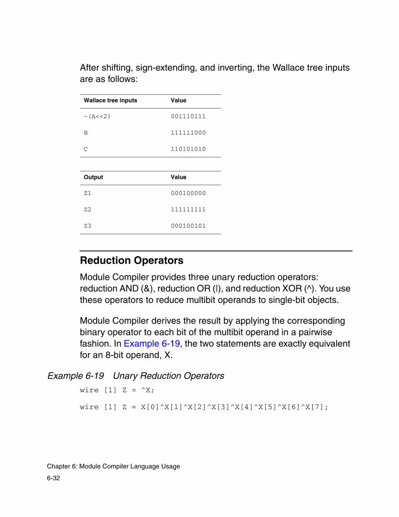
After shifting, sign-extending, and inverting, the Wallace tree inputs are as follows:
Reduction Operators
Module Compiler provides three unary reduction operators: reduction AND (&), reduction OR (|), and reduction XOR (^). You use these operators to reduce multibit operands to single-bit objects.
Module Compiler derives the result by applying the corresponding binary operator to each bit of the multibit operand in a pairwise fashion. In Example 6-19, the two statements are exactly equivalent for an 8-bit operand, X.
Example 6-19 Unary Reduction Operators
wire [1] Z = ^X;
wire [1] Z = X[0]^X[1]^X[2]^X[3]^X[4]^X[5]^X[6]^X[7];
Wallace tree inputs Value
~(A<<2) 001110111
B 111111000
C 110101010
Output Value
Z1 000100000
Z2 111111111
Z3 000100101
6-32
Chapter 6: Module Compiler Language Usage

Comparison Operators
The complete set of comparison operators ( ==, != , >, <, >=, and <= ) is supported.
The Equality Test
You implement the equality test by using the binary operator, ==. It requires two inputs, which can have any combination of signed and unsigned formats. The output is always a single-bit unsigned value, 1 if the two inputs are equal and 0 otherwise. The two inputs can have different widths.
Example 6-20 Binary Operator Usage
wire [1] Z;Z=A==B; wire [1] Z1;Z1=(A[8]<<1)==B;
This operator always treats the two inputs as integers. For example, if signed and unsigned inputs are compared, the signed input must be positive for the two to be considered equal.
The Not-Equal-To Test
The not-equal-to test is implemented by the != operator, which is identical to an equality test (==) followed by an invert (~).
Other Comparison Operators
The remainder of the comparison operators utilize subtraction. The decision is the signed bit of the result of the subtraction. These operators can perform comparisons such as (A + B) >= (A*C - B*D), using a single adder.
6-33
Logical, Reduction, Shift, and MUX Operators

Module Compiler computes the width of the operand that holds the result of the subtraction as the maximum width, using the following formula:
where wi is the width of the + and − operands and wj and wk are the widths of the * operands.
Equality Comparison
You perform the equality comparison by doing a bitwise XOR between the two inputs and then a NOR of all XOR outputs, using a Wallace tree.
Selectop
You can use the selectop attribute to control the ordering of select signals for shifters, rotators, and MUX-based multiplexers. When you set selectop to msb, Module Compiler orders the select inputs from the most significant bit (MSB) to the LSB: The delay from the LSB is the least, and the delay from the MSB is the greatest.
When selectop is set to lsb, the ordering is reversed: The delay from the LSB is the greatest. When selectop is set to auto, Module Compiler orders the select inputs to minimize the delay from the select inputs to the output, based on the select input arrival times.
Rotate and Shift
The rotate and shift operators provide left and right shifters and rotators that work with signed as well as unsigned data. The result is correct even when the input and output bit ranges do not match.
2log 2wi∑ 2 wj(∑ wk+ +( ) ) 1+
6-34
Chapter 6: Module Compiler Language Usage

The input data is always directly sign-extended if the output is wider than the input. For shift, if the output is narrower than the input, Module Compiler truncates the full-precision output after shifting. For rotate, if the output is narrower than the input, Module Compiler truncates the input to the width of the output and then rotates the input.
The shift operation uses the >> and << operators for right and left shift, respectively. These operators always perform an arithmetic shift: an approximation to division for right shift and to multiplication for left shift (one value is a power of 2). If you require a logical shift of a signed operand, you must first convert it to unsigned.
The rotate operation uses the >>> and <<< operators for right and left rotate, respectively. These operators perform a cyclical rotation of the bits either to the left or to the right. Unlike shifters, in which bits shifted out the ends are lost, the rotators shift bits out of one end and wrap them around to the other end so that no bits are lost.
The shift value must be positive. To reverse the shift direction, use the alternate operator when using constants.
When the shift value is a constant, the shift or rotate output is computed in advance and no hardware is generated. If the data input is constant, logic optimization is used to reduce the area.
Example 6-21 Rotate and Shift
wire [32] X;X=A<<<S; //rotate left
wire signed [32] X;X=~(A>>S); //shift right and invert
6-35
Logical, Reduction, Shift, and MUX Operators

Example 6-22 Shifting the Input With a Signal S
X[6] = (b5,b4,b3,b2,b1,b0)
Table 6-5 shows several functional examples in which the input, X, is shifted by a signal, S, with a value of 2. In this case, there is no fixed shift or bit ranging and the output has the same width as the input.
Example 6-23 Another Example of Shift
Z+X>>2;
If X is shifted by a constant 2, the shift-left results are the same as above (Table 6-5) and the shift-right results are as shown in Table 6-6. The result is the same for signed and unsigned inputs.
Table 6-5 Results of Example 6-22
Function Format Output
Z=X>>S Unsigned 0 0 b5 b4 b3 b2
Z=X>>S Signed b5 b5 b5 b4 b3 b2
Z=X<<S Either b3 b2 b1 b0 0 0
Z=X>>>S Either b1 b0 b5 b4 b3 b2
Z=X<<<S Either b3 b2 b1 b0 b5 b4
Table 6-6 Results of Example 6-23
Func Output
Z=X>>2 b5 b4 b3 b2
Z=X<<2 b3 b2 b1 b0 0 0
6-36
Chapter 6: Module Compiler Language Usage
The shifter and rotator are built with a sequence of 2-input multiplexer stages (log2(n) stages, where n is the number of bits in the shift operand). To maximize speed and minimize area, inverting multiplexers are used in all stages, except the last one if there is an odd number of stages. You can optionally specify that the output should be inverted.
Note: Inversion provides improvement of area and delay when there is an odd number of stages and degradation when there is an even number of stages.
In addition to the shift operator, Module Compiler provides a programmable shifter as a function, shiftlr. See the Module Compiler Reference Manual for more information about this function.
6-37
Logical, Reduction, Shift, and MUX Operators

Multiplexing
The multiplexing operation uses the ?: conditional operator, similar to C. You specify the signal used for selection to the left of ? and the list of signals to be selected to the right of ?. You separate the signals to be selected with colons (:).
Module Compiler selects these signals from right to left as the select input value increases from 0 to n−1. For example, if the select signal is 0, Module Compiler selects the rightmost signal. If the select signal is 1, Module Compiler selects the second-rightmost signal, and so on.
You can use an n-bit-wide select signal to multiplex 2n signals. It is not necessary to specify the entire range of inputs: If only m inputs are specified, then the top m+1 to 2n inputs are not connected and are treated as don’t care values for the purpose of the optimization.
It is also possible to create holes by specifying don’t care values, using the constant 'h x for the corresponding input. Use the don’t care values when possible to decrease the area required to implement the multiplexer.
Multiplexer Architectures
You can select the architecture of the multiplexer by using the muxtype attribute, as shown in Example 6-24 on page 6-40. If you set muxtype to mux, you get a MUX-based architecture. Other possible values are andor and tristate, which produce ANDOR-based and three-state-based multiplexers. The muxtype defaults to mux when muxtype is not specified or is set to auto. Each architecture accepts any number of inputs, of any width and format. Signed inputs are directly sign-extended as necessary.
6-38
Chapter 6: Module Compiler Language Usage

Multiplexer-Based Architectures
The MUX architecture is the best default choice and the most straightforward, because it provides generally good speed and area. It is constructed from standard MUX cells and is the most likely to be similar to what you would produce manually. This structure cannot take advantage of skewed data input arrival times but does optimize the structure when the select inputs have skewed arrival times, as determined by selectop.
If the select space is not full, meaning that fewer than 2n data inputs are provided for an n-bit select input, the unused select values are assumed to be don’t care values and are used to minimize the area. The behavioral model outputs X if unspecified select values are used, whereas the gate-level model outputs one of the data inputs. In general, this structure produces efficient results under degenerate conditions.
ANDOR-Based Architectures
The ANDOR-based architectures decode the select input and use the decoder outputs to gate (AND) each data input. The gated data inputs are then ORed together by use of a Wallace tree.
This structure has the advantage of being fully timing driven and thus should provide good performance for highly skewed input arrival times. However, it is generally larger than MUX-based implementations. Also, this structure is slower for inputs with no arrival time skew.
If the select space is not full, the output is 0 if an undefined select value is used. In general, this structure produces efficient results under degenerate conditions and is commonly used with only one
6-39
Logical, Reduction, Shift, and MUX Operators
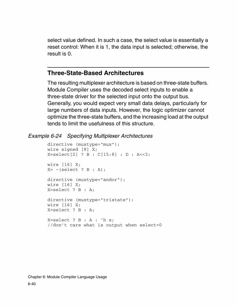
select value defined. In such a case, the select value is essentially a reset control: When it is 1, the data input is selected; otherwise, the result is 0.
Three-State-Based Architectures
The resulting multiplexer architecture is based on three-state buffers. Module Compiler uses the decoded select inputs to enable a three-state driver for the selected input onto the output bus. Generally, you would expect very small data delays, particularly for large numbers of data inputs. However, the logic optimizer cannot optimize the three-state buffers, and the increasing load at the output tends to limit the usefulness of this structure.
Example 6-24 Specifying Multiplexer Architectures
directive (muxtype="mux");wire signed [8] X;X=select[2] ? B : C[15:8] : D : A<<3;
wire [16] X;X= ~(select ? B : A);
directive (muxtype="andor");wire [16] X;X=select ? B : A;
directive (muxtype="tristate");wire [16] X;X=select ? B : A;
X=select ? B : A : 'h x; //don’t care what is output when select=0
6-40
Chapter 6: Module Compiler Language Usage

Decoding
Module Compiler provides a general decoder function that two of the MUX architectures use. You can also call the decoder function directly. It uses single-stage AND logic to generate each output. This approach is not particularly area-efficient for wide decoders but is reasonable in the range from 4 to 16 outputs. As the AND Wallace trees are used, this structure automatically adjusts to incoming delay skews.
Note: In a partial decoder, where not all 2n outputs are used, the remaining logic is not optimized to take advantage of this constraint, so you should not make the output range any wider than necessary.
Format Conversion Circuits
Format conversion circuits are used to convert wires from one data type to another or to convert wires from one format to another.
Saturation
The saturation function is used to convert an operand with one range of legal values into another operand with a smaller range of values. Operand bit-range selection is the simplest form of this conversion. All bits of the input that are outside the selected bit range are discarded. This approach produces potentially large errors and can result in instabilities in many recursive algorithms.
6-41
Format Conversion Circuits

The saturation function provides the minimum error conversion; in the output space, the closest value to the original input is selected as the output. That is, if the input exceeds the maximum or minimum value representable at the output, the output is set to the maximum or minimum value, respectively.
Module Compiler provides two functions for the saturation operation: sat and sati. Each function requires an input and an output. The sati function inverts the final result, and sat returns the true result. Inverting the output generally improves both area and delay, by allowing the use of an inverting rather than a noninverting MUX.
This function works with any combination of signed and unsigned operands at the input and output. The formats and bit ranges you choose for the input and output are important, because sat is a conversion from the input bit range and format to the output.
Example 6-25 Using the Saturation Function
input signed [8] X;wire signed [4] Z1,Z3;wire [4] Z2;wire [8] Z4;Z1=sat(X[7]); //unsigned -> signedZ2=sati(X); //same as Z2=~sat(X);Z3=sat(X); //signed -> signedZ4=sat(X[7:4]); //signed -> unsigned
Normalize
The normalization operation can be thought of as conversion from unsigned integer to floating-point format. It detects the number of leading 0s or 1s in the input and shifts the input left by this amount. The number of leading 0s or 1s is the exponent of the normalized number, and the shifted number is the mantissa.
6-42
Chapter 6: Module Compiler Language Usage

This operation can be specified with one of two functions. Use norm to remove leading 0s, and use norm1 to remove leading 1s. In either case, the mantissa is the first operand, the exponent is the second, and the data input is the third argument of the function.
If the width of the data input is not a power of 2, the input is left-shifted to make the width a power of 2. The shifted input is then normalized. Finally, the mantissa is right-shifted by the amount of the left shift.
The exponent is unsigned by default. It is also not allowed to exceed the declared range of the exponent operand; you should declare the width of the exponent operand to control the maximum number of shifts used to normalize the input. The input can be signed. Any necessary sign extension occurs before the normalization.
When the mantissa output is narrower than the input, the computation is performed with full precision (input width) and then the MSBs of the full-precision result are truncated to form the mantissa of the correct width.
Example 6-26 has a few examples showing the operation of normalization (leading 0s) for an exponent operand 2 bits wide.
Example 6-26 Leading-Zero Normalization
wire [8] MANT;
Input Output (mantissa) Output (exp)
10000000 10000000 0
01110101 11101010 1
00001110 01110000 3
6-43
Format Conversion Circuits

wire [2] EXP; //must be unsignednorm (MANT,EXP,IN);
Note that in the third example, the output is not fully normalized, because the exponent output was defined with only 2 bits. Therefore, the maximum exponent (shift) is 3, not 4.
The norm—see Example 6-28 on page 6-47—and norm1 functions use Wallace trees in the computation of the shift value and therefore deal well with arrival time skews in the high-order bits. A one-level lookahead technique is used to speed up the computation of the shift value.
Sequential Circuits
You can describe sequential circuits concisely by using library functions, which have the same general format and style as combinational functions. Automatic pipelining provides a mechanism for automatically inserting pipelines into designs to achieve the desired delay goal. You can stall all synthesized sequential elements except enabled shift registers.
For all designs, you can incorporate one or more clocks and delay goals. You use the clock and delay attributes to set the current clock and delay goal. All synthesized sequential elements use the current clock, which is not included in the sequential function call. Module Compiler uses the delay goal to determine the insertion point of automatic pipelines and to determine slack during logic optimization.
Module Compiler provides two basic register types: state and pipeline registers. State registers, such as accumulators, are a functional part of the architecture. You use pipeline registers only to
6-44
Chapter 6: Module Compiler Language Usage
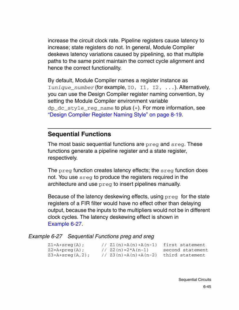
increase the circuit clock rate. Pipeline registers cause latency to increase; state registers do not. In general, Module Compiler deskews latency variations caused by pipelining, so that multiple paths to the same point maintain the correct cycle alignment and hence the correct functionality.
By default, Module Compiler names a register instance as Iunique_number (for example, IO, I1, I2, ...). Alternatively, you can use the Design Compiler register naming convention, by setting the Module Compiler environment variable dp_dc_style_reg_name to plus (+). For more information, see “Design Compiler Register Naming Style” on page 8-19.
Sequential Functions
The most basic sequential functions are preg and sreg. These functions generate a pipeline register and a state register, respectively.
The preg function creates latency effects; the sreg function does not. You use sreg to produce the registers required in the architecture and use preg to insert pipelines manually.
Because of the latency deskewing effects, using preg for the state registers of a FIR filter would have no effect other than delaying output, because the inputs to the multipliers would not be in different clock cycles. The latency deskewing effect is shown in Example 6-27.
Example 6-27 Sequential Functions preg and sreg
Z1=A+sreg(A); // Z1(n)=A(n)+A(n-1) first statementZ2=A+preg(A); // Z2(n)=2*A(n-1) second statementZ3=A+sreg(A,2); // Z3(n)=A(n)+A(n-2) third statement
6-45
Sequential Circuits

In the first statement, the old A is added to the new A, creating a very simple filter. The function sreg produces no latency, so no latency deskewing takes place.
In the second statement, the old A is added to the new A, but the old A has one cycle more latency than the new A, so latency deskewing first delays the new A by one cycle and then adds it to the old A.
In the third statement, you can see how to create a two-stage shift register without latency effects.
The eqreg, eqreg1, and eqreg2 functions provide variable-length shift registers. You use these functions to match the latency at different parts of the design.
For example, there might be three outputs, each driven by logic that has been automatically pipelined, so the latency can be different at each of the three outputs. You can use eqreg to force all outputs to have the latency of the most delayed output, regardless of the number of automatically inserted pipeline stages.
State Registers
You use the sreg function (Example 6-28) to create a state register of fixed length. The ensreg function is used to create a fixed-length state-shift register with an active-high enable control. When the enable is 1, the shift register is active and the data shifts with each clock rising edge. When the enable is 0, the shift register is inactive and no outputs change.
6-46
Chapter 6: Module Compiler Language Usage

When access to the taps is required, for a register of length n, up to n+1 outputs can be passed to the function at the end of the parameter list. The first is connected to the input, the second is the output of the first tap, and the last is the output of the nth tap.
The sreg function is affected by the delstate synthesis attribute. If delstate is greater than 0, pipeline loaning occurs. To disable pipeline loaning, set delstate back to 0. For more information, see “Pipeline Loaning” on page 10-19.
Example 6-28 State Register Example
X=sreg(A,1);//1-tap state register is equivalent to x=sreg(A)
directive(delstate=0);//have access to all taps, X_0 is the same as input, //X_4 is the final output
X=sreg(A,4,X_0,X_1,X_2,X_3,X_4);
X=ensreg(A,Y[3],4); //4-tap enable state reg
Scan Cells
The next sections discuss scan cells.
Scan Test
The scan attribute controls the conversion of flip-flops into their scan counterparts. When scan is on, the conversion takes place and Module Compiler builds the circuit with good area and delay estimates. When you set scan to off, no conversion takes place. During report generation, the scan flip-flops are converted back to the original cells.
6-47
Scan Cells
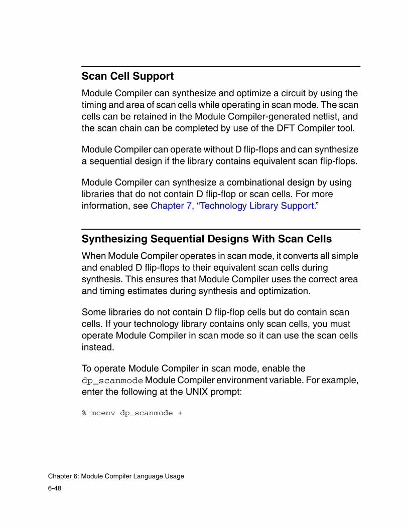
Scan Cell Support
Module Compiler can synthesize and optimize a circuit by using the timing and area of scan cells while operating in scan mode. The scan cells can be retained in the Module Compiler-generated netlist, and the scan chain can be completed by use of the DFT Compiler tool.
Module Compiler can operate without D flip-flops and can synthesize a sequential design if the library contains equivalent scan flip-flops.
Module Compiler can synthesize a combinational design by using libraries that do not contain D flip-flop or scan cells. For more information, see Chapter 7, “Technology Library Support.”
Synthesizing Sequential Designs With Scan Cells
When Module Compiler operates in scan mode, it converts all simple and enabled D flip-flops to their equivalent scan cells during synthesis. This ensures that Module Compiler uses the correct area and timing estimates during synthesis and optimization.
Some libraries do not contain D flip-flop cells but do contain scan cells. If your technology library contains only scan cells, you must operate Module Compiler in scan mode so it can use the scan cells instead.
To operate Module Compiler in scan mode, enable the dp_scanmode Module Compiler environment variable. For example, enter the following at the UNIX prompt:
% mcenv dp_scanmode +
6-48
Chapter 6: Module Compiler Language Usage

Alternatively, you can convert flip-flops into their scan equivalents by applying the scan attribute to the part of your Module Compiler Language design where you want to insert scan cells. For example,
directive(scan="on")
In scan mode, Module Compiler uses the scan cells during synthesis and optimization. However, by default, the scan flip-flops are converted to regular flip-flops during report generation. The following section explains how you can retain scan cells in the final netlist.
Keeping Scan Cells in the Final Netlist
You can control whether inserted scan cells are retained in the final netlist generated by Module Compiler, by using the dp_keepscan Module Compiler environment variable.
• Enabling dp_keepscan
When you operate in scan mode, the scan cells Module Compiler uses during synthesis are retained in the final netlist only if you also enable dp_keepscan. To enable dp_keepscan, enter the following at the UNIX prompt:
% mcenv dp_keepscan +
6-49
Scan Cells

• Disabling dp_keepscan (the default)
When you disable dp_keepscan, the scan flip-flops are converted back to their original D flip-flops. The conversion occurs after Module Compiler writes the design report and before it writes the netlist. By default, dp_keepscan is disabled. To disable dp_keepscan explicitly, enter the following at the UNIX prompt:
% mcenv dp_keepscan -
Module Compiler also generates a text file that lists instances of D flip-flops and their scan equivalents. This file is in the scan directory. This file is created only when dp_keepscan is disabled.
User-Instantiated Scan Cells
You can instantiate scan cells in your Module Compiler Language design. Module Compiler retains user-instantiated scan cells in the final netlist, regardless of how you set the dp_scanmode and dp_keepscan Module Compiler environment variables.
Scan Style Limitations
Module Compiler supports the multiplexed_flip_flop scan style only. You can choose other scan styles by taking the Module Compiler netlist into Design Compiler and using the DFT Compiler tool.
Module Compiler supports synthesis using scan cells in synchronous circuits.
6-50
Chapter 6: Module Compiler Language Usage
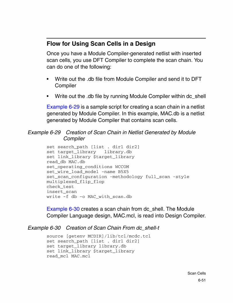
Flow for Using Scan Cells in a Design
Once you have a Module Compiler-generated netlist with inserted scan cells, you use DFT Compiler to complete the scan chain. You can do one of the following:
• Write out the .db file from Module Compiler and send it to DFT Compiler
• Write out the .db file by running Module Compiler within dc_shell
Example 6-29 is a sample script for creating a scan chain in a netlist generated by Module Compiler. In this example, MAC.db is a netlist generated by Module Compiler that contains scan cells.
Example 6-29 Creation of Scan Chain in Netlist Generated by Module Compiler
set search_path [list . dir1 dir2]set target_library library.dbset link_library $target_libraryread_db MAC.dbset_operating_conditions WCCOMset_wire_load_model -name B5X5set_scan_configuration -methodology full_scan -stylemultiplexed_flip_flopcheck_testinsert_scanwrite -f db -o MAC_with_scan.db
Example 6-30 creates a scan chain from dc_shell. The Module Compiler Language design, MAC.mcl, is read into Design Compiler.
Example 6-30 Creation of Scan Chain From dc_shell-t
source [getenv MCDIR]/lib/tcl/mcdc.tclset search_path [list . dir1 dir2]set target_library library.dbset link_library $target_libraryread_mcl MAC.mcl
6-51
Scan Cells
set_operating_conditions WCCOMset_wire_load_model -name B5X5mcenv dp_keepscan +mcenv dp_scanmode +compile_mclset_scan_configuration -methodology full_scan -stylemultiplexed_flip_flopcheck_testinsert_scanwrite -f db -o MAC_with_scan.dbreport_timing > timing_from_read_mcl.rep
Demultiplexing
Demultiplexing is the process of converting a high-speed serial data stream into n lower-rate parallel data streams. As the name implies, this process is the inverse of multiplexing, which serializes several parallel streams.
You implement demultiplexers by using a function called demux, which takes two signal inputs and a list of n outputs. The inputs are the data input and the select input.
The data input is demultiplexed, and the select input controls the demultiplexer. The integer input parameter specifies the demultiplexing ratio and the number of outputs. By default, the formats and widths of these outputs match those of the data input.
For proper operation, the select input must cycle through values of 0 to n − 1 for each positive edge of the current clock. The outputs change when the current clock goes high and select has a value of 0.1. The input values that arrive when the select input has a value of 0, 1, 2, ... n − 1 appear on the 0, 1, 2, ... n − 1 indexed output, respectively. Example 6-31 uses n = 4.
6-52
Chapter 6: Module Compiler Language Usage
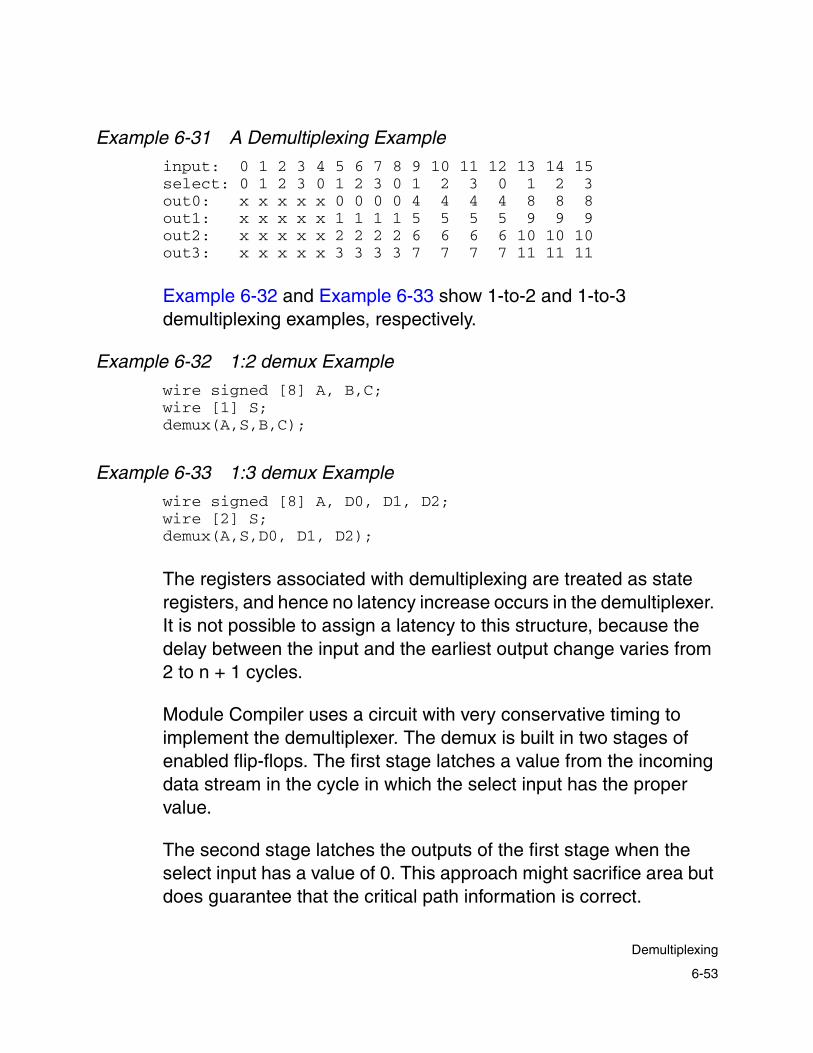
Example 6-31 A Demultiplexing Example
input: 0 1 2 3 4 5 6 7 8 9 10 11 12 13 14 15select: 0 1 2 3 0 1 2 3 0 1 2 3 0 1 2 3out0: x x x x x 0 0 0 0 4 4 4 4 8 8 8out1: x x x x x 1 1 1 1 5 5 5 5 9 9 9out2: x x x x x 2 2 2 2 6 6 6 6 10 10 10out3: x x x x x 3 3 3 3 7 7 7 7 11 11 11
Example 6-32 and Example 6-33 show 1-to-2 and 1-to-3 demultiplexing examples, respectively.
Example 6-32 1:2 demux Example
wire signed [8] A, B,C;wire [1] S;demux(A,S,B,C);
Example 6-33 1:3 demux Example
wire signed [8] A, D0, D1, D2;wire [2] S;demux(A,S,D0, D1, D2);
The registers associated with demultiplexing are treated as state registers, and hence no latency increase occurs in the demultiplexer. It is not possible to assign a latency to this structure, because the delay between the input and the earliest output change varies from 2 to n + 1 cycles.
Module Compiler uses a circuit with very conservative timing to implement the demultiplexer. The demux is built in two stages of enabled flip-flops. The first stage latches a value from the incoming data stream in the cycle in which the select input has the proper value.
The second stage latches the outputs of the first stage when the select input has a value of 0. This approach might sacrifice area but does guarantee that the critical path information is correct.
6-53
Demultiplexing

Black Box Support
Module Compiler provides support for black boxes that are described in a .db file, so that it can time through these entities. Examples of black box entities are physical RAM or ROM in a Module Compiler module. Module Compiler can instantiate any black box that supports an interface timing specification timing model.
Supported Features
The following are some of the major black box features Module Compiler supports:
• Black box cells are described in a .db file (single or multiple black boxes are allowed).
• Automated pseudocell generation is not affected by multiple .db files with one or many black boxes.
• Bused as well as bit-blasted ports (both I/Os) are supported.
• Interface timing specification timing models are used to describe a black box (see “Black Box Known Limitations” on page 6-56).
• Black boxes are treated as sequential leaf cells, and therefore timing through them is similar to existing flows (in-context timing-driven synthesis) that include registers. Module Compiler treats critical timing paths accordingly.
• No internal timing or functionality of black boxes is required in a .db file.
6-54
Chapter 6: Module Compiler Language Usage
• Pipelining around black boxes, such as autopipelining, is supported. The ResolveLatency and ResolveLatencyLoop functions also can be used (see “Black Box Known Limitations” on page 6-56).
• Module Compiler can perform latency deskewing or latency hiding (see “Black Box Known Limitations” on page 6-56).
• Both synchronous and asynchronous memory are supported.
• Output RTL and gate-level netlists are properly formatted to include black boxes.
• Also properly formatted are the report files generated by Module Compiler, including cell summary and critical path timing if any, through the black box.
Enabling Black Box Support
To enable black box support, include the Module Compiler environment variable dp_link_library (under $MCDIR/localadm/mc.env or in the design_dir/mc.env) to point to a black box .db file. At the UNIX prompt, enter the following in the $MCDIR/localadm or in your design directory:
% mcenv dp_link_library black_box_file
If there are multiple .db files for the black boxes, include them in a comma-separated list within quotation marks:
% mcenv dp_link_library "bb1.db,bb2.db,bb3.db"
If you have only one .db file, no quotation marks are needed:
% mcenv dp_link_library bb.db
6-55
Black Box Support

Recommended Methodology for Black Boxes
To use black boxes in your design, you can write a technology-independent function for each black box. This ensures that your design is technology independent in Module Compiler Language as well. The steps needed to perform this task are as follows:
1. Instantiate each technology-specific black box cell in the function.
2. Call these functions in your “design” Module Compiler Language code (which is technology independent).
3. Code autopipelining or ResolveLatency* as you would in a Module Compiler design without black boxes (see the next section, “Black Box Known Limitations”).
4. Click the Do All button.
Black Box Known Limitations
Only interface timing specification timing models are supported. The Stamp modeling language is not currently supported. The following limitations also apply:
• The interface timing specification has several timing model limitations for using black boxes.
- A black box cell should have one and only one clock. (Read or write enable signals in the case of asynchronous memory have a clock attribute in the .db file.)
- Setup constraints are specified with respect to the active edge of the clock.
6-56
Chapter 6: Module Compiler Language Usage

- Module Compiler ignores other timing constraints such as hold or recovery.
- The black box must use the same delay model and scaling factors as those in the technology library.
- Clear or preset timing arcs are ignored for synthesis.
These limitations exist due to the current Module Compiler built-in static timing analyzer.
• Black boxes must not contain bidirectional ports. If you use them, Module Compiler flags an error.
• There is no latency support for black boxes—black boxes cannot have inherent latency. As a result, Module Compiler pipelining is not affected. The Module Compiler latency counter does not add any black box latency, nor can you tag latencies to primary input signals.
• Input signals to a black box cannot have any latency. (This limitation is due to a restriction that does not allow instantiated technology-specific sequential cells with input latencies.) This restriction can be overcome with the use of ResolveLatency functions.
• Design report files and RTL and gate-level netlists do not reflect any presumed latency effects of a black box.
6-57
Black Box Support

Signal Manipulation Functions
The Module Compiler library provides several functions for manipulating signals. These functions do not perform any actual arithmetic or logical operation. Rather, you can use them to manipulate signal attributes such as size, timing, format, and so on.
Load Isolation and Buffering
Although the function synthesis routines automatically create buffer trees within each function to prevent overloading, your network description might contain large fanouts that cause overloading. If the overloading is severe enough, a rule violation occurs that is corrected during optimization.
During synthesis, however, the delay estimates of the overloaded nets are inaccurate, potentially causing pipelining problems. Module Compiler provides two functions that help alleviate overloading: buffer and isolate, shown in Example 6-34.
Example 6-34 isolate and buffer
input [8] A;wire [8] ANC; //must match A!ANC=isolate(A); //ANC has buffer depth 2buffer (ANC,2); //build buffer tree at output of ANC
isolate
The isolate function is provided to isolate heavy loads from the critical paths. It inserts a set of noninverting buffers between the input and output.
6-58
Chapter 6: Module Compiler Language Usage
The less-critical paths should be driven from the output and the more-critical paths from the input. The logic optimizer removes buffers that are not needed, either because the circuit contains sufficient slack or because you incorrectly assessed which operand was more critical.
buffer
The buffer function causes a buffer tree to be built with the depth specified (the default is 1). The maximum buffer depth supported is 5, which should be more than sufficient.
Unlike the isolate function, buffer is used in situations requiring a symmetric buffer tree. There is no way to connect some paths to a part of the buffer tree closer to the root. However, you can always buffer the output of isolate.
Note: The instances produced by the buffer function are affected by the attributes in effect when the signal being buffered is defined. They are not affected by the attributes in effect when the buffer statement is encountered.
The buffer tree is built with inverters, except for the last stage, where the depth is odd and therefore uses noninverter buffers. In general, the logic optimizer removes and/or merges parts of the buffer tree whenever possible to improve circuit performance and area. A portion of a buffer tree of depth 3 is shown in Figure 6-1. Note that only one stage is noninverting.
6-59
Signal Manipulation Functions

Figure 6-1 Buffer Tree
Signal Concatenation: cat
It is sometimes necessary or convenient to create operands that are a concatenation of existing operands. The cat function performs signal concatenation.
The cat function takes a list of signals separated by commas. The bits are copied from the input signals, in order, to the output. The MSB of the leftmost (first) input becomes the MSB of the result, and the LSB of the rightmost (last) input becomes the LSB of the result. By default, the format is the same as that of the first input and the width of the concatenation result is the sum of the widths of the inputs.
Example 6-35 Signal Concatenation
input [8] A,B,C;wire X;X=cat(C[2],A[4],B[6:5]);//X=C[2],A[4],B[6],B[5]
Original operand output
New operand outputs
6-60
Chapter 6: Module Compiler Language Usage

Three-States: join
Although three-state drivers should be avoided when possible in ASIC designs, Module Compiler provides limited support for these constructs. The join function can be used to connect two or more wires in a bitwise fashion. A warning is generated if any of the drivers of the net are not three-state drivers. A module input cannot be an input to join.
In Example 6-36, the outputs of two 2-input three-state multiplexers are joined to form a 4-input MUX.
Example 6-36 Three-State Example
module mux1 (A,B,C,D,S,Z);input [8] A,B,C,D;input [2] S;output [8] Z;directive (muxtype="tristate");wire [8] A1=S ? 'hx : 'hx : B : A;wire [8] A2=S ? D : C : 'hx : 'hx;wire [8] E=join(A1,A2);Z=E;
endmodule
Module Compiler Generic Cell Library
The Module Compiler generic cell library is a collection of low-level functions. Each function in the library is linked to a corresponding technology-specific cell, if one exists, regardless of the cell and pin names the vendor uses. If there is no corresponding cell in the technology library, Module Compiler synthesizes the generic cell function from two or more technology-specific cells.
6-61
Module Compiler Generic Cell Library

If you need to describe a structure at the gate level, you should use the Module Compiler generic cell library functions rather than the library your vendor provided. This helps maintain technology and vendor portability.
All Module Compiler generic functions begin with a mcgen_ prefix, which keeps generic function names unique and prevents name clashes with existing technology cell names.
When the technology library contains several equivalent cells, Module Compiler chooses the best one during optimization (unless optimization has been disabled). Module Compiler always attempts to use the fastest cell during synthesis. The Module Compiler Reference Manual contains a complete list of the functions in the Module Compiler generic cell library.
Most generic functions accept bused inputs and outputs. Only those functions that already have bused inputs or outputs and those functions with more than one output cannot accept bused arguments.
When a function is called with bused arguments, Module Compiler automatically generates an array of instances, one instance for each output bit. If any input is narrower than the output, the input is sign- or zero-extended in the same manner as other function calls.
Example 6-37 shows the construction of a technology-independent ripple adder, using the generic function mcgen_fa1a. Note how the mcgen_and2a function creates an array of 2-input AND gates. The R input is sign-extended to the width of the X bus.
6-62
Chapter 6: Module Compiler Language Usage

Example 6-37 Writing Standard Code
function adder (Z,X,Y);input X,Y;integer w=width(X);output [w:0] Z;wire [1] repl(i,w,",") {S{i},C{i}},C{w};C0=0;repl(i,w) {mcgen_fa1a (S{i},C{i+1},X[i],Y[i],C{i});} //ripple adderZ=(C{w},repl(i,w,",") {S{w-i-1}});
endfunction
module foo (X,Y,Z,R);input signed [1] R;input [8] X,Y;output [9] Z;wire [8] XR;XR=mcgen_and2a(X,R); //array of 2-input ORsZ=adder(Y,XR);
endmodule
Technology-Specific Cells
This section covers Module Compiler support of technology-specific cells.
Although Module Compiler has a rich library of synthesizable functions and generic cell library elements, you might need to instantiate a cell from the technology-specific library or a netlist of library elements into the design. It is also possible, with some additional work, to insert a cell that is not in the installed technology library into your design.
6-63
Technology-Specific Cells

Note that there is an interoperability limitation for cell naming within any technology library. There cannot be a leading period, “.”, in the cell name. This limitation is for the first character only. A period can occur after the first letter of the cell name.
In all cases, you call a Module Compiler Language function for the cell being inserted into the design. Your interface to the function is in the library browser of the GUI.
Cells not in the technology library are located in the “misc” category, and technology library cells are in one of the other categories. You insert the cell by calling the appropriate function. Outputs of the function must come before inputs in the parameter list.
There are two reasons why you should avoid overusing thesefunctions:
• These functions, unlike synthesized functions, are technology dependent. Moving your design to another technology could require changes to the Module Compiler Language code or the netlist.
• Some advantages Module Compiler provides during synthesis will not be available to you, including automatic pipelining; latency deskewing; and multiple architectures for structures such as adders, multipliers, and multiplexers.
Inserting Technology-Specific Cells in the Design
You can easily insert a cell from a technology library into your design. Module Compiler defines a function for each technology library cell. The functions for cells with one output and no buses accept bused inputs and outputs.
6-64
Chapter 6: Module Compiler Language Usage

Module Compiler automatically generates an array of instances for these cells, one instance for each output bit. If any input is narrower than the output, the input is sign-extended in the same manner as other function calls.
Example 6-38 illustrates how to create a Module Compiler Language function for a technology-specific cell.
This example computes Z(n) = Y(n) + X(n − 1). You implement the adder as a ripple adder, using instances of the fa1a1 cell. Module Compiler generates an array of fd1a1 registers to form XR. CLK is connected to the clock input of each fd1a1, because CLK is signed and is thus sign-extended, whereas each fd1a1 receives a different data input. The output, Z, is driven by an array of OB4 output buffer cells from the technology library.
Example 6-38 Using Instances by Name
function adder (Z,X,Y);input X,Y;integer w=width(X);output [w:0] Z;wire [1] repl(i,w,",") {S{i},C{i}},C{w};C0=0;repl (i,w) {fa1a1 (S{i},C{i+1},X[i],Y[i],C{i});}//ripple adderZ=(C{w},repl(i,w,",") {S{w-i-1}});
endfunction
module pipe (X,Y,Z);input [8] X,Y;output [9] Z;wire [8] XR;XR=fd1a1(X,CLK); //array of FFswire [9] Z1=adder(Y,XR);Z=OB4(Z1); //output buffer instances
endmodule
6-65
Technology-Specific Cells

The method used in this example is clearly not the best way to implement Z(n) = Y(n) + X(n − 1). Using instances of library cells requires more lines of code and does not benefit from the multiple adder architectures and the synthesis optimization available from Module Compiler. Also, the code in Example 6-38 might not work for another technology, an outcome that takes away the benefits of design reuse.
When inserting one of several equivalent technology-specific cells directly into a design, you should insert the fastest (and likely the largest) equivalent cell. This approach has two effects:
• The delays computed during synthesis are less sensitive to estimated loading inaccuracies.
• The optimizer is more likely to find a good solution, because the optimizer is better at reducing area than at improving performance.
Size-Only Optimization Support
Module Compiler recognizes cells in a technology library with the use_for_size_only attribute. When Module Compiler reads the technology library, it detects all cells that have this attribute.
These cells are treated as don’t use cells for Module Compiler synthesis and optimization and can be found in the Don’t Use section of the Module Compiler Library Report. For an example of this section, see “Library Report” on page 7-20.
If the cells with the use_for_size_only attribute are instantiated in any Module Compiler Language code, Module Compiler preserves any instances of these cells through optimization, and they appear in the generated netlist.
6-66
Chapter 6: Module Compiler Language Usage

Specifying Ports (Explicit Port Mapping)
For cell instantiation, you can specify a mapping between module ports and function arguments explicitly. This technique can reduce coding errors, because the ordering between ports and arguments does not have to match. Example 6-39 shows explicit port mapping between module ports and function arguments.
Example 6-39 Explicit Port Mapping Between fx_OR and Module top
function fx_OR (Z, A, B);output Z;input A,B;Z = A | B;
endfunction module top (Z_top, A_top, B_top);
input [1] A_top, B_top ; output [1] Z_top; fx_OR or_inst1 (.B(B_top), .A(A_top), .Z(Z_top));endmodule
In Example 6-39, function fx_OR has input arguments A and B and output argument Z. Module top has input ports A_top and B_top and an output port, Z_top. The function instantiation
fx_OR or_inst1 (.B(B_top), .A(A_top), .Z(Z_top));
specifies an explicit mapping between the ports of module top with the arguments of function fx_OR. Note that the order of ports and arguments does not match in Example 6-39.
Figure 6-2 illustrates explicit port mapping between port B_top and function argument B for Example 6-39.
6-67
Technology-Specific Cells

Figure 6-2 Mapping Between Argument B and Parameter B_top
Using explicit port mapping, you can order ports and arguments independently, as shown in Figure 6-2.
Using Groups in Complex Designs
Some designs must be divided into sections sharing one or more common attributes or constraints. You can use Module Compiler directives to set the clock, delay, enable, group, pipeline, dcopt, and logopt attributes for sections of the design.
These attributes control the timing, power calculation, naming, and optimization of the groups. When the value of one of these attributes is set in a directive, that value is in effect until another value is provided for the attribute.
function fx_OR (Z, A, B);output Z;input A,B;Z = A | B;
endfunction module top (Z_top, A_top, B_top);
input 1] A_top, B_top ; output [1] Z_top; fx_OR or_inst1 ( .B(B_top), .A(A_top), .Z(Z_top));endmodule
6-68
Chapter 6: Module Compiler Language Usage

Group Names
You use the group attribute to define a group and provide it with a name. There are three primary reasons to form a new group in a design:
• Each group must have a single delay goal. If the delay goal is changed, a new group must be created.
• It is convenient in large designs to break the design into smaller groups for statistical and debugging purposes. Each group has a critical path and a complete set of statistics (delay, area, power, and the like). Proper use of groups makes the job of determining the critical (delay, area, or power) portion of the design much easier.
• Groups can assist in placement. If you use the long instance-name option, each instance name will have the group name as a suffix to allow grouping in the floorplanner or place and route system. Module Compiler allows you to use hierarchical group names.
The enable (pipestall) and clockIn Signal Declarations
You can stall all synthesized flip-flops, whether they are state or pipeline registers, by setting the enable(or pipestall) attribute to the name of the stall control signal. By default, the pipeline is not stalled. The pipeline stalls when the stall control signal is low.
The enable attribute is a replacement for the pipestall attribute. However, code using either attribute is supported. The two attributes have the same functionality, except that you can use enable to
6-69
Using Groups in Complex Designs

declare an enable signal as an input port by using the signal declaration enableIn. This declaration and the enable attribute are discussed later in more detail.
The clockIn declaration allows you to specify a clock as an input port. Module Compiler does not buffer the clock. It does buffer the enable signal if required (as it does with other signals). With Module Compiler, the clock and enable inputs are never pipelined.
Module Compiler defines the width and format of the clock (or enable) signal as 1-bit and signed, respectively. You are not allowed to define the width and format of the clock or enable signals; doing so results in an error message. Example 6-40 illustrates the use of clockIn to declare a clock signal.
Example 6-40 clockIn Examples
clockIn ABC_clk; //available as a signaldirective (group="G1", clock="ABC_clk", delay=4000); //delay goal =4000
clockIn XYZ_clk //available as a signalXCLK=XYZ_clk & X;//use XCLK2, delay goal=4000//XCLK2 cannot be used as another clockdirective (group="G2", clock="XYZ_clk", delay=6000);//delay goal =6000
In Example 6-40, ABC_clk is defined in group G1. Module Compiler gets its delay goal from the delay attribute, which is set to 4,000 ps. Another clock, XYZ_clk, is defined in group G2, with a delay goal of 6,000 ps. You can specify only one clock per group.
6-70
Chapter 6: Module Compiler Language Usage

Example 6-41 myCLK
module test (myCLK, myEnable, other_ports);clockIn myCLK; //declares a signal myCLKenableIn myEnable; //declares a signal myEnable//...code continues...
directive (clock = "myCLK"); //clock is available to Module Compilerdirective (enable = "myEnable"); //enable is available to Module Compiler
//...code continues...endmodule
In Example 6-41, you would specify the clock in the input port list with
clockIn myCLK;
Similarly, you would specify the enable signal in the input port list with
enableIn myEnable;
Between the signal declaration clockIn and the attribute clock used in the directive statement, the clock is available for use as it is for any other Module Compiler signal. Module Compiler recognizes a signal as a clock only when it is sees the respective directive statement.
In the same way, Module Compiler recognizes the enable signal only when it is sees the respective directive statement. Between the signal declaration, enableIn, and the attribute enable, the enable signal is available for use, as it is with any other Module Compiler signal.
6-71
Using Groups in Complex Designs

Example 6-42 shows that you can pass a clock or enable as a string, input, or clock signal argument to a function. The only restriction, as mentioned earlier, is that the formal argument cannot have a format or size specified.
Example 6-42 fCLK
module testf(fCLK,other_ports);clockIn fCLK;myFunc(fCLK, ...);//...code continues...
endmodule
function myFunc(ABC, ...);clockIn ABC;
When writing RTL/gate or VHDL/Verilog output, Module Compiler maintains the position of the clock or enable as specified by the module interface. However, you cannot declare the scope of the clock or enable signal. If you write the following statements,
clockIn global fCLK;
or
enableIn global eCLK;
Module Compiler issues a warning.
To name your clock or enable signal, you follow the standard Module Compiler naming conventions. As with all signal names, you cannot have a trailing underscore (_) in a signal name for a clock or an enable. For example, a clock or an enable named my_clock1_ is not allowed.
6-72
Chapter 6: Module Compiler Language Usage

You can gate a clock or an enable, but the gated output cannot be a clock or an enable. In other words, you are not allowed to create a new clock or enable—such as a gated clock or a divided clock—from an existing clock or enable in your design.
If you gate a clock or an enable, the gates will be subject to optimization and the Module Compiler optimization process will not distinguish the clock or enable gates from other gates in your design.
You can gate the clock and use the gated output wherever appropriate, such as for enabling a latch or RAM. Similarly, you can gate the enable and use the gated output, for example, as an enable input of ensreg, shown in Figure 6-3.
You should note that the indelay and inload attributes do not have any impact on clock. However, the indelay and inload attributes have an impact on enable.
Module Compiler will deskew the enable of ensreg if required. An example of ensreg(D,EN) is shown in Figure 6-3.
Figure 6-3 Deskew Enable of ensreg
latency = 0 E
EN
enable (pipestall)
D
latency = 4
Q
ensreg (D, EN)
6-73
Using Groups in Complex Designs

In Figure 6-3, Module Compiler ensures that the enable signal has the same latency, 4, as signal D.
Multiple Clocks
Module Compiler supports multiple clocks in a design, although each group can have only one clock. All clocks are global signals that can be referenced throughout all levels of your design. You can declare the current clock by setting the clock attribute to the name of the current clock. In doing so, you should be careful not to declare clocks explicitly as wires.
All sequential circuits without explicit clock connections use the current clock. For example, sreg and preg have no clock argument and always use the current clock.
Automatic pipelines are also connected to the current clock. You can also explicitly use any clock wherever Module Compiler requires a signal, such as an enable input to a latch.
Example 6-43 is a circuit containing three clocks, CLK1, CLK2, and CLK3. The registers in X are connected to CLK1, those in Y are connected to CLK2, and those in Z are connected to CLK3.
Note that whenever you change the current clock or delay goal, you must also change the group. This also holds true for sequential and combinational circuits.
6-74
Chapter 6: Module Compiler Language Usage

Example 6-43 Using Multiple Clocks
module clkdemo (A,B,Z,Y,X); directive (logopt="off"); directive (group = "G1", delay=4000, clock="CLK1"); directive (logopt="on"); input [8] A,B; wire [16] temp1 = A*B;output [16] X = sreg(temp1); // sreg() gets CLK1directive (group="G2", delay=2500, clock="CLK2"); wire [9] temp2 = A+B;output [9] Y = sreg(temp2); // sreg() gets CLK2directive (group="G3", delay=3000, clock="CLK3"); wire [9] temp3 = A-B;output [9] Z = sreg(temp3); // sreg() gets CLK3endmodule
Group Timing and Pipelining
The delay and pipeline attributes are used to control the timing of a section of the design.
delay
The value of delay affects the synthesis of some structures and the optimization of all instances within a group. The value of the attribute is the current path delay goal and uses picosecond units.
To prevent overconstrained circuits, the delay attribute affects only the drivers of the path endpoints (either flip-flop inputs or module outputs) and not the endpoints themselves. Therefore, it is important to ensure that the drivers of all endpoints have the correct delay goal.
6-75
Using Groups in Complex Designs
In addition, because each group (as defined by the group attribute) must not have multiple delay goals, the delay attribute should be used in conjunction with the group attribute. Note that the Module Compiler environment variable dp_opt and the Optimization field in the GUI provide the initial value of the delay attribute.
pipeline
The pipeline attribute has a Boolean value indicating whether automatic pipelining is enabled within a section of the design. When pipelining is enabled (on), Module Compiler inserts pipelines if the delay exceeds the current value of the delay goal.
When pipelining is disabled (off), automatic register insertion is not employed, even if the delay exceeds the delay goal. One exception to this is pipeline loaning, which occurs transparently.
Pipelining sections can be smaller or larger than the groups defined with the group attribute. You can set the initial value of the pipeline attribute, using the command-line option or the GUI.
Multiple Delay Goals
Consider a design with multiple clocks in which all clocks can be formed by division of a master clock by an integer. Although it is possible to use multiple clocks for this type of problem, the enable registers provide a simple mechanism for implementing multiple clocks. There is still a single master clock, but now there are many local enables that generate local clocks (within the flip-flops) of different frequencies.
You should divide the circuit into groups, with all the logic within a group operating at the same frequency. In addition, frequency changes of the data must occur at registers or primary inputs and the
6-76
Chapter 6: Module Compiler Language Usage

groups must contain the registers or inputs that are referenced within the group. The delay goal, group name, and AC switching factor are then changed immediately before the group is described.
Example 6-44 shows a circuit utilizing two clocks, one of which is half the frequency of the other.
Example 6-44 Clock Groups
function clkgrp(name, delay);string name;integer delay;directive global(group=name,delay=delay);
endfunction
module test (A,B,Z,RESET );integer del=10000; //master clk cycle time
clkgrp (fastA,del);input [8] A,B;input [1] RESET;wire [8] Y;output [8] Z;Y=A+B;wire [1] EN,ENN;EN=sreg(ENN,1); //generate the enable circuitENN=~EN&RESET;
clkgrp (slow,del*2);wire [16] S1,S1A;wire [8] S2;S1=ensreg(S1A,EN,1);S2=ensreg(Y,EN,1);S1A=S1*S2;
clkgrp (fastB,del);wire [16] S3;S3=sreg(S1);Z=S3[15:8]^S3[8]+A;
endmodule
6-77
Using Groups in Complex Designs

Example 6-45 on page 6-84 has three groups in the circuit. Two (fastA and fastB) are operating at 10 ns, and the other (slow) is operating at 20 ns to allow more time to process S1*S2, which is needed only every other cycle.
Note that there is a function, clkgrp, that changes the delay goal and the group name, together. Also note that with this setup, the inputs to the S1 and S2 registers are paths with a 10-ns delay goal because the drivers of the end of the path are in a group with a 10-ns delay. However, the outputs of the registers and the multiplier have a 20-ns delay goal.
At S3, the input path has a 20-ns delay goal and the output has a 10-ns delay goal. The output, Z, changes every 10 ns and is optimized with a 10-ns delay goal.
When a design has multiple delay goals, the most critical path is not always the longest path. Consider Example 6-45 on page 6-84, in which a path in the slow group has a delay of 19 ns and one in the fast group has a delay of 11 ns. The path in slow has 1 ns of slack, whereas the one in fastB has −1 ns of slack. Therefore, the critical path reported is that in fastB, rather than the one in slow. This is why it is important to look at slack rather than delay when using multiple delay goals.
Disabling Module Compiler Logic Optimization
When you do not want to minimize the delay in a section of a design, you can disable the logic optimizer of Module Compiler with the logopt attribute. This is a Boolean attribute that enables logic optimization when set to on.
6-78
Chapter 6: Module Compiler Language Usage

When it is set to off, all logic optimization is disabled, including fixing rule violations. Logic optimization is on by default and should be disabled only on rare occasions.
Disabling Design Compiler Optimization
You can selectively optimize sections of Module Compiler code by using Design Compiler. Generally, arithmetic logic benefits the least from optimization by Design Compiler and AND-OR logic benefits the most.
You can choose to optimize all, some, or none of your circuit by setting the dcopt attribute. This is a Boolean attribute that enables Design Compiler optimization when set to on and disables optimization when set to off. The entire circuit is sent to Design Compiler but Design Compiler does not touch any instance that was created when dcopt was off. Design Compiler optimization is on by default.
Note: This feature works only when you are running Design Compiler from Module Compiler. The selective optimization automatically sets the dont_touch attribute on the cells using a postprocessing script.
Report Control
To request that additional group and critical path information be printed in the report file, you can insert functions into the Module Compiler Language input file. Because these functions are placed in the input file, the design must be resynthesized each time the reporting functions are changed or added.
6-79
Report Control

Groups in Module Compiler can be either hierarchical or flat (disjoint). You can create disjoint groups by choosing group names without a dot (.). Each of these groups represents a non-overlapping portion of the design.
You create hierarchical groups by inserting a dot (.) in the group name. Each portion of the group name following a dot represents a division of the group whose name precedes the dot. For example, A.1 and A.2 are two disjoint divisions of the group A and A.1.1 and A.1.foo are two disjoint divisions of the group A.1.
Group Analysis
By default, Module Compiler provides two reports for the groups in a design:
• It generates a list of all the top-level groups. In this list, the groups A, A.1, A.2, and A.1.1 are combined to form the group A. If you have not used hierarchical group names, this list contains all the groups in the design.
• It generates a list of all the groups. In this list, A, A.1, A.2, and A.1.1 are reported independently.
You can request additional group information by using the showgroup function. Each showgroup function accepts a group name pattern and causes one list of groups to be inserted into the report file. The list contains all the groups whose names match the pattern.
The pattern is supplied as a dot-separated list of names. Module Compiler locates all the groups matching the names supplied in the pattern. You can use * to match any name at any level of the hierarchy.
6-80
Chapter 6: Module Compiler Language Usage
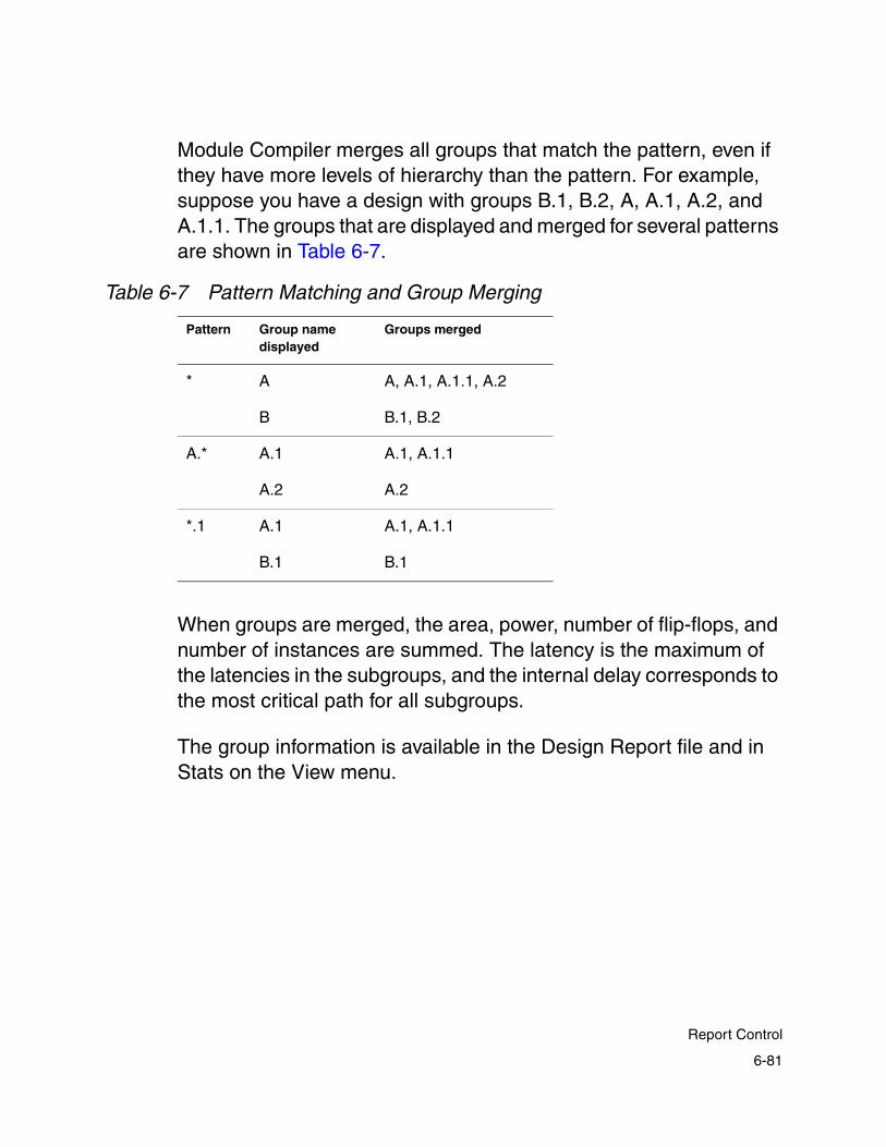
Module Compiler merges all groups that match the pattern, even if they have more levels of hierarchy than the pattern. For example, suppose you have a design with groups B.1, B.2, A, A.1, A.2, and A.1.1. The groups that are displayed and merged for several patterns are shown in Table 6-7.
When groups are merged, the area, power, number of flip-flops, and number of instances are summed. The latency is the maximum of the latencies in the subgroups, and the internal delay corresponds to the most critical path for all subgroups.
The group information is available in the Design Report file and in Stats on the View menu.
Table 6-7 Pattern Matching and Group Merging
Pattern Group name displayed
Groups merged
* A A, A.1, A.1.1, A.2
B B.1, B.2
A.* A.1 A.1, A.1.1
A.2 A.2
*.1 A.1 A.1, A.1.1
B.1 B.1
6-81
Report Control

Path Analysis
Module Compiler provides critical path analysis for the entire design and for each user-defined group. In addition, four Module Compiler Language functions are provided to allow you to specify additional critical paths for analysis. These functions are summarized in Table 6-8.
User-defined critical paths have two modes, short and full. The critmode function sets the current reporting mode. Use full mode to display full paths, such as the critical paths shown for the design and groups.
Use short mode to display only the name and the critical path length, for output similar to a datasheet. The mode affects all critical paths printed until you change the mode by calling critmode again. By default, the reporting mode is full.
It is possible to prevent critical paths from passing through internal operands by using the disablepath function. This function takes one string argument that is the operand name or operand bit range
Table 6-8 Path Analysis Functions
Function Use
critpath (string start, string end, string name);
Finds the critical path from start to end, using name
disablepath (string point); Prevents paths from going through point
enablepath (string point); Allows paths to go through point
critmode (string mode); Sets the reporting mode
6-82
Chapter 6: Module Compiler Language Usage

through which the critical path is not allowed to pass. Using a value of ∗ disables all internal paths. Input operands cannot be disabled with this command.
The enablepath function does the opposite of the disablepath function. It takes one string argument that is the operand name or operand bit range through which the critical path is allowed to pass. Using a value of ∗ enables all internal paths.
The critpath function takes three string values (start, end, name) and finds the most critical path—the path with the least slack at the endpoint. The critical path does not go through internal operands that have been disabled and not subsequently enabled.
Module Compiler names the path with the name string value and lists it in the User Critical Path section of the report file. The value of start can be an operand name, an operand bit range, or * to start at any input. Both end and start take values of an operand name, a bit range, or * to end at any output.
Additionally, you can use ∗∗ to end at any output or other path endpoint (such as a flip-flop D input). CLK can be used as an end name to enable paths that stop at register inputs.
The order of any critpath function relative to the other three functions is very important, because critmode, enablepath, and disablepath determine how subsequent critpath functions behave.
6-83
Report Control

Creating a Video Processor
Suppose you want to create a video front-end processor that uses an RGB-to-YUV converter. In addition, you need to process each output of the converter with a FIR filter.
Because you want a compiler that can be called with different values to generate different video processors, rather than a static piece of code, you need to pass some parameters to the module. This compiler can be built as shown in Example 6-45.
Example 6-45 A Complete Example/* define some macros for use throughout this exercise */#define COEFFS1 replicate(integer i=0;i<taps;i=i+1){ C{i},}#define COEFFS replicate(i=0;i<taps;i=i+1){ C{i},}#define TAPS replicate(i=0;i<=taps;i=i+1){ TAP{i},}
/* build a FIR filter using the given coefficients */function fir1 (OUT,IN, taps, COEFFS1,wOut);
integer taps; //the number of taps in the filterinput IN; //this is the data input, declared outsideinput COEFFS; //taps number of C inputsinteger wOut;output signed [wOut-2] OUT; //declare OUT with enough bitswire if (formatStr(IN)==signed) { signed } [width(IN)-2] OUT_DELIN,TAPS;OUT_DELIN=sreg(IN,taps,TAPS); //the state shift register
/* compute the inner product */
OUT=replicate(i=0;i<taps;i=i+1; "+"){TAP{i+1}*C{i}};endfunction
/* build a converter from RGB format to YUV format */function RGBtoYUV (Y, U, V, R , G, B, width);
integer width; //width is the number of bits in the outputinput R,G,B; //function inputs are not declared, must be declared /
/elsewhereoutput signed [width-2] U,V; //Y,U,V are created hereoutput unsigned [width-2] Y;Y=87*R+G*37+B*15;U=-33*R+15*G-97*B;V=109*R-49*V+65*B;
6-84
Chapter 6: Module Compiler Language Usage
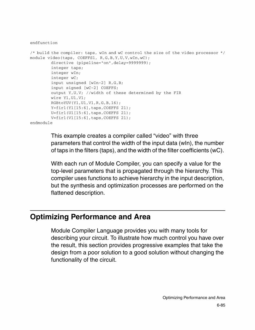
endfunction
/* build the compiler: taps, wIn and wC control the size of the video processor */module video(taps, COEFFS1, R,G,B,Y,U,V,wIn,wC);
directive (pipeline="on",delay=9999999);integer taps; integer wIn;integer wC;input unsigned [wIn-2] R,G,B;input signed [wC-2] COEFFS;output Y,U,V; //width of these determined by the FIR wire Y1,U1,V1;RGBtoYUV(Y1,U1,V1,R,G,B,16);Y=fir1(Y1[15:6],taps,COEFFS 21);U=fir1(U1[15:6],taps,COEFFS 21);V=fir1(V1[15:6],taps,COEFFS 21);
endmodule
This example creates a compiler called “video” with three parameters that control the width of the input data (wIn), the number of taps in the filters (taps), and the width of the filter coefficients (wC).
With each run of Module Compiler, you can specify a value for the top-level parameters that is propagated through the hierarchy. This compiler uses functions to achieve hierarchy in the input description, but the synthesis and optimization processes are performed on the flattened description.
Optimizing Performance and Area
Module Compiler Language provides you with many tools for describing your circuit. To illustrate how much control you have over the result, this section provides progressive examples that take the design from a poor solution to a good solution without changing the functionality of the circuit.
6-85
Optimizing Performance and Area

The following example performs a color space conversion, as shown in some of the previous examples. This is a simple operation, but it is important in video applications.
Example 6-46 Color Space Conversion
Y=77R+150G+29BU=128R-107G-21BV=-43R-85G+128B
Clearly, you need to perform nine multiplications and six additions or subtractions. You could take a somewhat naive design approach: construct a module with nine multiplications and the six adders/subtracters and supply the coefficients later (outside of Module Compiler), as shown in Example 6-47.
Note that this example involves extra work to break the equation for Y into subequations for Y1, Y2, Y3, and Y4. Now each of these internal values is generated with a carry-propagate adder.
Example 6-47 A Complete RGB-to-YUV Design
module RGB_var_fastcla_serial_nocs (Y, U, V, R , G, B, C00, C01, C02, C10, C11, C12, C20, C21, C22);directive(fatype="fastcla",delay=1);input [8] R,G,B;input signed [8] C00,C01,C02,C10,C11,C12,C20,C21,C22; wire signed [16] U1,U2,U3,U4;wire signed [16] V1,V2,V3,V4;wire unsigned [16] Y1,Y2,Y3,Y4;output signed [16] U,V;output unsigned [16] Y;Y1=C00*R; Y2=C01*G; Y3=C02*B; Y4=Y1+Y2; Y=Y4+Y3;U1=C10*R; U2=C11*G; U3=C12*B; U4=U1+U2; U=U4+U3;V1=C20*R; V2=C21*G;V3=C22*B; V4=V1+V2; V=V4+V3;
endmodule
6-86
Chapter 6: Module Compiler Language Usage

After running the previous example, you obtain the results in Table 6-9.
It is hard to determine how well this case works until you compare it with another implementation. For comparison, change the adder type from fastcla to clsa; clsa is expected to perform better for skewed delay cases such as multipliers. You change the directive statement to get the input in Example 6-48.
Example 6-48 Changing Adder From fastcla to clsa
module RGB_var_clsa_serial_nocs (Y, U, V, R , G, B, C00, C01, C02, C10, C11, C12, C20, C21, C22);
directive(fatype="clsa", delay=1);input [8] R,G,B;input signed [8] C00,C01,C02,C10,C11,C12,C20,C21,C22; wire signed [16] U1,U2,U3,U4;wire signed [16] V1,V2,V3,V4;wire unsigned [16] Y1,Y2,Y3,Y4;output signed [16] U,V;output unsigned [16] Y;Y1=C00*R; Y2=C01*G; Y3=C02*B; Y4=Y1+Y2; Y=Y4+Y3;U1=C10*R; U2=C11*G; U3=C12*B; U4=U1+U2; U=U4+U3;V1=C20*R; V2=C21*G; V3=C22*B; V4=V1+V2; V=V4+V3;
endmodule
Table 6-9 Results of Example 6-47
Module Sections Delay Latency
RGB_var_fastcla_serial_nocs 7143 17.26 0
6-87
Optimizing Performance and Area

After rerunning Module Compiler, you obtain the results in Table 6-10.
As expected, you made some progress in both area and delay, due solely to the ability of the clsa adder to optimize its structure around the delay skews in the circuit.
Now it should be clear that you can make some significant improvements by merging the five equations for each color-component output. For each output, you will have a single Wallace tree implementing three multiplications and two additions, followed by a single carry-propagate adder. You should have done this first, because the input is much simpler, as shown in Example 6-49.
Example 6-49 Merging Equations for Each Color Component
module RGB_var_clsa_par_nocs (Y, U, V, R , G, B, C00, C01, C02, C10, C11, C12, C20, C21, C22);directive(fatype="clsa",delay=1);input [8] R,G,B;input signed [8] C00,C01,C02,C10,C11,C12,C20,C21,C22; output signed [16] U,V;output unsigned [16] Y;Y=C00*R+C01*G+C02*B;U=C10*R+C11*G+C12*B;V=C20*R+C21*G+C22*B;
endmodule
Table 6-10 Results of Adder Change
Module Sections Delay Latency
RGB_var_fastcla_serial_nocs 7143 17.26 0
RGB_var_clsa_serial_nocs 6051 16.46 0
6-88
Chapter 6: Module Compiler Language Usage

After running Example 6-49, you get the result in Table 6-11.
Clearly, reducing the number of carry-propagate adders by merging the equations results in even greater savings of area and performance than simply changing the adder types.
There is another method for achieving nearly identical results, as in Example 6-49: using the carrysave attribute. In Example 6-50, you have not merged the equations but instead have defined all the internal nodes to be carry-save, and therefore Module Compiler does not generate carry-propagate adders at these nodes.
Example 6-50 Implementing the carrysave Attribute
module RGB_var_clsa_serial_cs (Y, U, V, R , G, B, C00, C01, C02, C10, C11, C12, C20, C21, C22);directive(fatype="clsa",delay=1);input [8] R,G,B;input signed [8] C00,C01,C02,C10,C11,C12,C20,C21,C22; wire signed [16] U1,U2,U3,U4;wire signed [16] V1,V2,V3,V4;wire unsigned [16] Y1,Y2,Y3,Y4;output signed [16] U,V;output unsigned [16] Y;directive(carrysave="on");Y1=C00*R; Y2=C01*G; Y3=C02*B; Y4=Y1+Y2;U1=C10*R; U2=C11*G; U3=C12*B; U4=U1+U2;V1=C20*R; V2=C21*G; V3=C22*B; V4=V1+V2;directive(carrysave="off");
Table 6-11 Result of Merging Equations
Module Sections Delay Latency
RGB_var_fastcla_serial_nocs 7143 17.26 0
RGB_var_clsa_serial_nocs 6051 16.46 0
RGB_var_clsa_par_nocs 4612 13.18 0
6-89
Optimizing Performance and Area

Y=Y4+Y3;U=U4+U3;V=V4+V3;
endmodule
After running Example 6-50, you get the result in Table 6-12.
The carrysave case results in only slight degradation of area and delay over the fully merged case. This example shows the power of using carrysave; area and delay are improved, and access to internal nodes such as Y1, Y2, and Y3 is possible.
Finally, because the coefficients are already known, Module Compiler optimizes the circuit with these coefficients. Note that in Example 6-51, you have a level of hierarchy through a function that looks like a variable-coefficient matrix multiplier. However, in the module, you call the function with the fixed-coefficient values. Module Compiler automatically determines that the multiplications can be optimized.
Table 6-12 Result of carrysave Implementation
Module Sections Delay Latency
RGB_var_fastcla_serial_nocs 7143 17.26 0
RGB_var_clsa_serial_nocs 6051 16.46 0
RGB_var_clsa_par_nocs 4612 13.18 0
RGB_var_clsa_serial_cs 4725 13.30 0
6-90
Chapter 6: Module Compiler Language Usage

Example 6-51 Implementing Fixed Coefficients
function RGB (Y, U, V, R , G, B, C00, C01, C02, C10, C11, C12, C20, C21, C22);
input R,G,B;input C00, C01, C02, C10, C11, C12, C20, C21, C22; output U,V;output Y;Y=C00*R+C01*G+C02*B;U=C10*R+C11*G+C12*B;V=C20*R+C21*G+C22*B;
endfunction
module RGB_fixed_clsa_par (Y, U, V, R , G, B);directive(delay=1,fatype="clsa");integer width;input [8] R,G,B; output signed [16] U,V; output unsigned [16] Y;RGB (Y,U,V,R,G,B,77,150,29,128,-107,-21,-43,-85,128);
endmodule
After running Example 6-51, you get the results in Table 6-13.
Table 6-13 Results of Fixed-Coefficients Implementation
Module Sections Delay Latency
RGB_var_fastcla_serial_nocs 7143 17.26 0
RGB_var_clsa_serial_nocs 6051 16.46 0
RGB_var_clsa_par_nocs 4612 13.18 0
RGB_var_clsa_serial_cs 4725 13.30 0
RGB_fixed_clsa_par 1652 10.03 0
6-91
Optimizing Performance and Area

The use of the fixed coefficients has provided enormous benefits. The area dropped by nearly 66 percent from the previous best case (Example 6-50), and the delay decreased by nearly 25 percent. Compared to the original case (Example 6-47), the gains are even greater.
You could take this case further by utilizing pipelining to achieve even higher performance levels. You are invited to try this as the final exercise of this chapter.
6-92
Chapter 6: Module Compiler Language Usage

7Technology Library Support 7
This chapter provides an overview of how to use third-party technology libraries with Module Compiler. It includes the following sections:
• Library Functionality
• Delay, Capacitance, and Area Units
• CBA and Non-CBA Libraries
• Timing Models
• Setup and Hold Time Models
• Wire Load Models
• Derating Model
• Resistance Models
7-1

• Sequential Models
• Required and Recommended Cell Sets
• Library Report
7-2
Chapter 7: Technology Library Support

Library Functionality
The technology library provided by your vendor supplies critical information to Module Compiler. This information includes the following:
• The functionality, timing, and loading of all cells in the library
• The estimated wire load models
• The operating conditions
• The derating models
Module Compiler reads one or more industry-standard Synopsys .db-format files. This allows Module Compiler to fit well in Synopsys Design Compiler flows. As you work with Module Compiler and libraries, you need to understand how Synopsys .db models and objects map to Module Compiler data structures.
Module Compiler computation algorithms and streamlined internal data structures for model storage result in fast runtimes. However, not all models and objects can benefit from this efficiency, because not all Synopsys .db models and objects can map directly to Module Compiler data structures. As a result, in some cases, you might notice small differences between the results obtained with Module Compiler and those you get with other Synopsys tools, such as Design Compiler.
Keep in mind that Module Compiler is a pre-layout synthesis tool, in which wire load capacitances are not known. As a result, it cannot produce exact timing results.
7-3
Library Functionality

Delay, Capacitance, and Area Units
Module Compiler operates in technology-independent units to make the input constraints and output values relatively insensitive to vendor library variations (see Table 7-1). It is important to know that Module Compiler stores all values as integers, to speed computation. Module Compiler therefore scales and converts all floating-point numbers in the vendor library to integers and stores these integers internally.
A standard load is defined to be the input capacitance of the smallest inverter in the library.
CBA and Non-CBA Libraries
Module Compiler has two distinct ways of computing area, one for CBA (cell-based array) libraries and one for all other libraries. The CBA architecture is a heterogeneous array containing compute and drive sections, making area computation more complex.
Table 7-1 Module Compiler Units
Element Unit
Timing constraints
Integer ps
Delay values in reports
Floating-point ns
Loading constraints
Integer tenths of standard load
7-4
Chapter 7: Technology Library Support
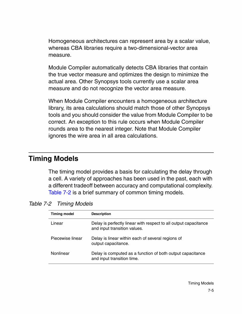
Homogeneous architectures can represent area by a scalar value, whereas CBA libraries require a two-dimensional-vector area measure.
Module Compiler automatically detects CBA libraries that contain the true vector measure and optimizes the design to minimize the actual area. Other Synopsys tools currently use a scalar area measure and do not recognize the vector area measure.
When Module Compiler encounters a homogeneous architecture library, its area calculations should match those of other Synopsys tools and you should consider the value from Module Compiler to be correct. An exception to this rule occurs when Module Compiler rounds area to the nearest integer. Note that Module Compiler ignores the wire area in all area calculations.
Timing Models
The timing model provides a basis for calculating the delay through a cell. A variety of approaches has been used in the past, each with a different tradeoff between accuracy and computational complexity. Table 7-2 is a brief summary of common timing models.
Table 7-2 Timing Models
Timing model Description
Linear Delay is perfectly linear with respect to all output capacitance and input transition values.
Piecewise linear Delay is linear within each of several regions of output capacitance.
Nonlinear Delay is computed as a function of both output capacitance and input transition time.
7-5
Timing Models

Currently the transition time dimension is not used in the piecewise linear model. The linear and the nonlinear delay models support dependency on both input (transition time) and output capacitances.
Runtime performance of delay calculation improves when simpler models are employed. To speed up Module Compiler, reduce the number of breakpoints in either dimensions or both dimensions or use only one dimension.
Module Compiler uses the nonlinear timing model for all delay calculations to provide timing estimates that are as accurate as possible. This model uses the input transition time in addition to the output capacitance to determine the delay through a cell.
There are two variations of this model. In one, the cell delay and the transition time are provided. In the other, the propagation delay and the transition time are provided (cell delay = propagation delay + transition time).
All Synopsys timing models are mapped into the nonlinear timing model. With the exception of the edge-rate effects of the CMOS2 model, there is very little error in the mapping.
Because Module Compiler ignores the CMOS2 edge-rate effects, Module Compiler results are somewhat optimistic relative to those of other Synopsys tools when the nonlinear timing model is employed. This nonlinear timing model supported by Module Compiler is becoming the industry standard.
7-6
Chapter 7: Technology Library Support
Setup and Hold Time Models
Module Compiler supports scalar setup times and ignores hold times entirely. In addition there is some inaccuracy for libraries containing transition-dependent setup times. Because there is only one setup time per path, this effect is not cumulative.
Wire Load Models
The wire load model Module Compiler provides comprises estimates of the load of the unrouted nets in the design as a function of the number of pins or fanouts on the net. Module Compiler estimates the loading based on statistical properties of the place and route tools and on the size of the region in which the design is placed.
Module Compiler supports the Synopsys piecewise linear wire load model. You can select any wire load model used by Module Compiler at any time. However, the design has only one active wire load model at once.
For convenience, Module Compiler defines several pure linear wire load models, which can be used for comparing technology libraries that have inconsistent wire load models.
Wire load names are stored as technology-independent environment variables. To set the wire load model, you need to set the appropriate Module Compiler environment variable. For example, if the wire-load model is ETC_RF and the technology name is My_CMOS, you set the variable as follows:
%mcenv dp_dc_wireload_My_CMOS ETC_RF
7-7
Setup and Hold Time Models

This example assumes that you have set the technology name in the Module Compiler environment by entering
%mcenv dp_tech My_CMOS
The wire load model name is stored as a technology-dependent environment variable. When you change technologies, Module Compiler automatically remembers the wire load model you last used.
Wire load model name
Standard loads/fanout
synlinear0 0
synlinear1 1
synlinear2 2
synlinear2.5 2.5
synlinear3 3
synlinear5 5
synlinear10 10
7-8
Chapter 7: Technology Library Support

Derating Model
The derating model provides a method for computing the loading, delay, and resistance effects in the circuit as you change the process, temperature, and voltage from those under which the library data was measured.
The derating model used in Module Compiler is linear for each variable. That is, the actual delay can be computed for any process, voltage, or temperature as follows:
Equation 7-1 Derating Model
where P0, V0, and T0 are the process, voltage, and temperature under which the library data was measured, respectively. Module Compiler supports the independent derating of the rise and fall values of setup time, cell delay, transition delay, and propagation delay. Wire load and pin capacitance are derated by use of the same linear technique.
Do not select the values of P, V, and T directly. Instead, select one of the named operating conditions (opconds). Each named opcond corresponds to a value of process, voltage, and temperature.
Like wire load names, the named opconds are stored as technology-dependent environment variables, so you can change technologies without having to reenter the appropriate opcond information. Module Compiler automatically creates the opcond synlibcond, which corresponds to the conditions under which the library data was measured.
t P V T, ,( ) t P0 V0 T0, ,( ) 1 KP P P0–( )+( ) 1 KV+ V V0–( )( ) 1 KT+ T T0–( )( )⋅ ⋅ ⋅=
7-9
Derating Model

Module Compiler currently supports one derating model for the whole library. This means that the same set of scaling factors (k factors in the Synopsys .lib file) is used for derating all components in the library.
If multiple scaling groups are defined in the library, Module Compiler uses the first scaling group to determine the scaling factors. This might cause some inaccuracies in the timing numbers, but the inaccuracies are typically very small.
Resistance Models
Module Compiler now takes wire resistance into account. You can select from three cases:
• best_case_tree
• worst_case_tree
• balanced_tree
For example, to set the case to balanced_tree, you must set the Module Compiler environment variable as follows:
% mcenv dp_treetype balanced_tree
If you do not set the wire load model, the default is auto. With this setting, Module Compiler looks at the operating conditions in your library to set the case.
7-10
Chapter 7: Technology Library Support

Sequential Models
Module Compiler does not support the state table method of representing sequential elements. If you need to use a library employing this method, contact your Module Compiler applications support representative for a workaround solution.
Required and Recommended Cell Sets
This section covers the required (basic) cell and recommended cell sets for use with Module Compiler. Basic cells are presented first. Then other required and recommended cells are listed, grouped by the type of function being synthesized.
Look in the “Library Report” on page 7-20 to see if a given type of cell is available in the currently loaded technology library. A sample library report is provided at the end of this chapter.
Module Compiler can construct all cells, excluding required cells, as pseudocells if they are not available directly in the vendor’s library. It has the ability to build all the appropriate pseudocells. Understandably, properly designed and implemented native cells provide advantages over pseudocells in area, delay, power, and place and route complexity.
Module Compiler builds pseudocells automatically and stores them in a local cache library. Prior to running Module Compiler, you can also prebuild pseudocells to create a read-only global pseudocell library that can be shared by multiple designers. You can find detailed information on how Module Compiler builds pseudocells in “Building Pseudocell Libraries” on page 2-14.
7-11
Sequential Models

The cell names used are the Module Compiler generic cell library names. The functionality of these cells can be found in the Module Compiler Reference Manual.
The following cells are listed by the type of function being synthesized and are prioritized as follows:
• Basic (required) cells
• Should-have cells
• Recommended
These cells are covered in the following tables.
Basic Cells (Required)
For sequential circuits, Table 7-3 shows the cells that are required for Module Compiler to run.
For sequential designs, if the technology library does not have a D flip-flop but does have a scan cell, Module Compiler can use the scan cell instead. For more information, see “Scan Test” on page 6-47.
Table 7-3 Required Library Cells for Sequential Designs
Basic cell Type
mcgen_inv1a Inverting internal buffer
mcgen_nand2a 2-input NAND/AND gate
mcgen_nor2a 2-input NOR/OR gate
mcgen_fd1a D flip-flop
7-12
Chapter 7: Technology Library Support

For combinational circuits, Table 7-4 shows the cells that are required for Module Compiler to run. Note that the D flip-flop cell is not required.
Although you can run Module Compiler with just the cells listed in Table 7-3 and Table 7-4, doing so does not create designs with the best quality of results (QoR).
Cells Most Libraries Should Have
In order of priority, after required cells, Table 7-5 shows the cells you should have in your technology library.
Table 7-4 Required Library Cells for Combinational Designs
Basic cell Type
mcgen_inv1a Inverting internal buffer
mcgen_nand2a 2-input NAND/AND gate
mcgen_nor2a 2-input NOR/OR gate
Table 7-5 Cells You Should Have
Cell Type
mcgen_mx2a 2:1 MUX
mcgen_mx2d 2:1 MUX, inverting output
mcgen_fd1c D flip-flop, inverted output
mcgen_fde1c Enable flip-flop, inverted output
mcgen_xor3a 3-input XOR gate
mcgen_xnor3a 3-input XOR gate
mcgen_ha1a 1-bit half adder
7-13
Required and Recommended Cell Sets

Additional Recommended Cells
In order of priority, after required cells and cells listed in Table 7-5, the cells in Table 7-6 are the next 12 recommended cells.
mcgen_ha1b Half adder, active-low carry-in
mcgen_ha2a Half adder, inverted carry-out
mcgen_hacs1b 1-bit full carry-select half adder, active-low carry-in
mcgen_hacs2a 1-bit full carry-select half adder, inverted carry-out
mcgen_ao1f AND2C into OR2B
mcgen_oa1f OR2C into AND2B
Table 7-6 Additional Recommended Cells
Cell Type
mcgen_buf1a Noninverting internal buffer
mcgen_buf2a Inverting, noninverting internal buffer
mcgen_fde1a Enable flip-flop
mcgen_fa1a 1-bit full adder
mcgen_fa1b 1 bit full adder, CI inverted
mcgen_fa2a 1-bit full adder, COUT inverted
mcgen_faccs1b 1-bit full carry-select adder, CI inverted
mcgen_facs1b 1-bit full carry-select adder, CI inverted
mcgen_facs2a 1-bit full carry-select adder, COUT inverted
Table 7-5 Cells You Should Have (Continued)
Cell Type
7-14
Chapter 7: Technology Library Support

Inverters
The following cell is required:
mcgen_inv1a
Buffers
The following cells are recommended:
• mcgen_buf1a
• mcgen_buf2a
mcgen_facs3a 1-bit full carry-select adder, no carry-in
mcgen_facs4a 1-bit full carry-select adder, no carry-in
mcgen_mule2a Booth encoder
mcgen_mulpa1b Booth partial product generator
mcgen_mulpa2b Booth partial product generator
mcgen_xnor2a 2-input XNOR gate
mcgen_xor2a 2-input XOR/XNOR gate
Table 7-6 Additional Recommended Cells (Continued)
Cell Type
7-15
Required and Recommended Cell Sets

MUX-Based Multiplexers, Shifters, and Rotators
MUX-based multiplexers, shifters, and rotators can be built with the required basic cells, but for the best results, you should have the following cells:
• mcgen_mx2a
• mcgen_mx2d (2:1 MUX with inverting output)
In addition, the following cells are for building efficient multiplexers:
• mcgen_mx3a
• mcgen_mx4a
Flip-Flops
The following cell is required for synthesizing sequential elements:
mcgen_fd1a—for sreg, preg, and autopipelining without stall
The following cells are recommended for synthesizing sequential elements:
mcgen_fde1a—for ensreg and stall modes
The following inverted versions are cells you should have for minimizing inverters:
• mcgen_fd1c
• mcgen_fde1c
7-16
Chapter 7: Technology Library Support

To fully support scan test mode, use
• mcgen_fdm1a—when mcgen_fd1a is needed
• mcgen_fdem1a—when mcgen_fde1a is needed
Module Compiler can use cells with both true and inverted outputs to replace mcgen_fd1a, mcgen_fde1a, mcgen_fdm1a, and mcgen_fdem1a.
Latches
The following cells are for synthesizing latches and netlist memories. Equivalent cells with multiple outputs can also be used.
• mcgen_ld1a
• mcgen_ld1b
• mcgen_ld1c
AND-OR Trees
The following cells are required:
• mcgen_nand2a
• mcgen_nor2a
Module Compiler can use the following cells when it is building trees based on AND and OR functions.
• mcgen_and2a – mcgen_and8a
• mcgen_nand3a – mcgen_nand8a
7-17
Required and Recommended Cell Sets

• mcgen_nor3a – mcgen_nor8a
• mcgen_or2a – mcgen_or8a
XOR Trees
The following cells are recommended:
• mcgen_xor2a
• mcgen_xnor2a
You should have the following cells for building XOR trees:
• mcgen_xor3a
• mcgen_xnor3a
Adder Cells
The following cell is recommended for building any adder structures:
mcgen_fa1a
You should have the following cells for building adder structures:
mcgen_ha1a
The following cells are recommended for building optimized ripple adder types:
• mcgen_fa2a
• mcgen_fa1b
7-18
Chapter 7: Technology Library Support
The following cells are recommended for building csa and clsa adder types:
• mcgen_facs2a
• mcgen_facs1b
• mcgen_facs3a
• mcgen_facs4a
The following are cells you should have for getting efficient incrementors and comparators for csa and clsa:
• mcgen_hacs2a
• mcgen_hacs1b
• mcgen_ha2a
• mcgen_ha1b
The following cells are recommended for getting efficient incrementors and comparators for csa and clsa:
• mcgen_facs2a
• mcgen_faccs1b
The following are cells you should have for building cla and fastcla adder types, incrementors, and comparators:
• mcgen_ao1f
• mcgen_oa1f
7-19
Required and Recommended Cell Sets

The following cells are recommended for building Booth multipliers:
• mcgen_mule2a
• mcgen_mulpa1b
• mcgen_mulpa2b
Library Report
The library report (see Example 7-1) lists the operating conditions, models, and cells. You can see the technology library by choosing Library Report from the View menu. This report has the following sections:
• List of named operating conditions and P, V, T values
• List of wire load models
• List of Module Compiler generic cells and the technology-specific equivalent cells, if any
• List of technology-specific cells mapped to Module Compiler synthesis cells
• List of pseudocells
• List of don’t use cells
• List of untyped cells
• List of equivalent cells
The sections of the library report are discussed after Example 7-1.
7-20
Chapter 7: Technology Library Support
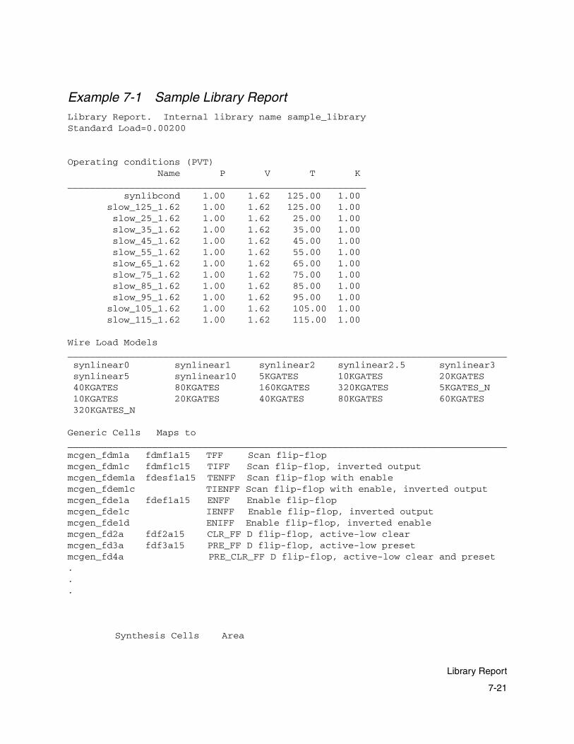
Example 7-1 Sample Library ReportLibrary Report. Internal library name sample_libraryStandard Load=0.00200
Operating conditions (PVT) Name P V T K_____________________________________________________ synlibcond 1.00 1.62 125.00 1.00 slow_125_1.62 1.00 1.62 125.00 1.00 slow_25_1.62 1.00 1.62 25.00 1.00 slow_35_1.62 1.00 1.62 35.00 1.00 slow_45_1.62 1.00 1.62 45.00 1.00 slow_55_1.62 1.00 1.62 55.00 1.00 slow_65_1.62 1.00 1.62 65.00 1.00 slow_75_1.62 1.00 1.62 75.00 1.00 slow_85_1.62 1.00 1.62 85.00 1.00 slow_95_1.62 1.00 1.62 95.00 1.00 slow_105_1.62 1.00 1.62 105.00 1.00 slow_115_1.62 1.00 1.62 115.00 1.00
Wire Load Models______________________________________________________________________________ synlinear0 synlinear1 synlinear2 synlinear2.5 synlinear3 synlinear5 synlinear10 5KGATES 10KGATES 20KGATES 40KGATES 80KGATES 160KGATES 320KGATES 5KGATES_N 10KGATES 20KGATES 40KGATES 80KGATES 60KGATES 320KGATES_N
Generic Cells Maps to______________________________________________________________________________mcgen_fdm1a fdmf1a15 TFF Scan flip-flopmcgen_fdm1c fdmf1c15 TIFF Scan flip-flop, inverted outputmcgen_fdem1a fdesf1a15 TENFF Scan flip-flop with enablemcgen_fdem1c TIENFF Scan flip-flop with enable, inverted outputmcgen_fde1a fdef1a15 ENFF Enable flip-flopmcgen_fde1c IENFF Enable flip-flop, inverted outputmcgen_fde1d ENIFF Enable flip-flop, inverted enablemcgen_fd2a fdf2a15 CLR_FF D flip-flop, active-low clearmcgen_fd3a fdf3a15 PRE_FF D flip-flop, active-low presetmcgen_fd4a PRE_CLR_FF D flip-flop, active-low clear and preset...
Synthesis Cells Area
7-21
Library Report
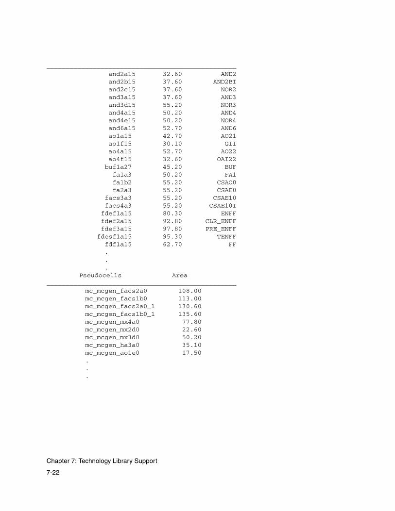
_________________________________________________ and2a15 32.60 AND2 and2b15 37.60 AND2BI and2c15 37.60 NOR2 and3a15 37.60 AND3 and3d15 55.20 NOR3 and4a15 50.20 AND4 and4e15 50.20 NOR4 and6a15 52.70 AND6 ao1a15 42.70 AO21 ao1f15 30.10 GII ao4a15 52.70 AO22 ao4f15 32.60 OAI22 buf1a27 45.20 BUF fa1a3 50.20 FA1 fa1b2 55.20 CSAO0 fa2a3 55.20 CSAE0 facs3a3 55.20 CSAE10 facs4a3 55.20 CSAE10I fdef1a15 80.30 ENFF fdef2a15 92.80 CLR_ENFF fdef3a15 97.80 PRE_ENFF fdesf1a15 95.30 TENFF fdf1a15 62.70 FF . . .
Pseudocells Area_________________________________________________ mc_mcgen_facs2a0 108.00 mc_mcgen_facs1b0 113.00 mc_mcgen_facs2a0_1 130.60 mc_mcgen_facs1b0_1 135.60 mc_mcgen_mx4a0 77.80 mc_mcgen_mx2d0 22.60 mc_mcgen_mx3d0 50.20 mc_mcgen_ha3a0 35.10 mc_mcgen_ao1e0 17.50 . . .
7-22
Chapter 7: Technology Library Support

Don’t Use Cells Area_________________________________________________ facs1b1 97.80 facs1b2 97.80 facs1b3 97.80 facs2a1 97.80 facs2a2 95.30 facs2a3 95.30 facsf1b1 90.30 facsf1b2 90.30 facsf1b3 92.80 facsf2a1 105.40 facsf2a2 105.40 facsf2a3 105.40 filler 2.50 pclk1a15 27.60 pclk1a2 10.00 . . .
Untyped Cells Area_________________________________________________ and2a1 12.50 and2a2 12.50 and2a3 12.50 and2a6 17.60 and2a9 20.10 and2b1 12.50 and2b2 12.50 and2b3 17.60 and2b6 20.10 and2b9 30.10 and2c1 7.50 and2c2 10.00 and2c3 10.00 and2c6 17.60 and2c9 25.10 and3a1 15.10 and3a2 15.10 and3a3 17.60 and3a6 20.10 and3a9 22.60 and3b1 22.60 and3b15 42.70 and3b2 22.60 and3b3 22.60 and3b6 22.60
7-23
Library Report

and3b9 27.60 and3c1 15.10 and3c15 42.70 . . .
Can’t Use Cells Area_________________________________________________ facs1b1 97.80 facs1b2 97.80 facs1b3 97.80 facs2a1 97.80 facs2a2 95.30 facs2a3 95.30 facsf1b1 90.30 facsf1b2 90.30 facsf1b3 92.80 facsf2a1 105.40 facsf2a2 105.40 facsf2a3 105.40 fdef2a1 67.70 fdef2a15 92.80 CLR_ENFF fdef2a2 67.70 fdef2a3 67.70 fdef2a6 75.30 fdef2a9 80.30 fdef2c1 72.80 fdef2c15 100.40 fdef2c2 72.80 fdef2c3 72.80 fdef2c6 77.80 fdef2c9 80.30 fdef3a1 72.80 fdef3a15 97.80 PRE_ENF fdef3a2 72.80 fdef3a3 72.80 fdef3a6 77.80 fdef3a9 85.30 fdesf2a1 85.30 fdesf2a15 110.40 fdesf2a2 85.30 fdesf2a3 85.30 fdesf2a6 87.80 . . .
7-24
Chapter 7: Technology Library Support

Library Cell Summary_________________________________________________ 522 VENDOR cells 250 GENERIC cells 20 PSEUDO cells 60 SYN cells 27 DONTUSE cells 111 CANTUSE cells
168 FF cells 46 DL cells
Equivalent Cells______________________________________________________________ mcgen_ld1b ldf1b1 ldf1b15 ldf1b2 ldf1b3 ldf1b6 ldf1b9 mcgen_ld1c mcgen_ld1a ldf1a1 1df1a15 ldf1a2 ldf1a3 ldf1a6 ldf1a9 mcgen_ld2b mcgen_ld2a ldf2a1 ldf2a15 ldf2a2 ldf2a3 ldf2a6 ldf2a9 mcgen_1dm1b ldmf1b1 ldmf1b15 ldmf1b2 1dmf1b3 1dmf1b6 1dmf1b9 mcgen_ldm1c mcgen_ldm1a 1dmf1a1 ldmf1a15 ldmf1a2 1dmf1a3 ldmf1a6 ldmf1a9 mcgen_ld4a mcgen_1dm2a 1dmf2a1 ldmf2a15 ldmf2a2 ldmf2a3 ldmf2a6 ldmf2a9 fdf1d1 fdf1d15 fdf1d2 fdf1d3 fdf1d6 fdf1d9 mcgen_fd1b fdf1b1 fdf1b15 fdf1b2 fdf1b3 fdf1b6 fdf1b9 mcgen_fd1c fdflc1 fdf1c15 fdf1c2 fdf1c3 fdf1c6 fdf1c9 mcgen_fd1a fdf1a1 fdf1a15 fdf1a2 fdf1a3 fdf1a6 fdf1a9 mcgen_fd6a mcgen_fde1c mcgen_fjk1a mcgen_fde1d . . .
7-25
Library Report
Named Opconds Report Section
Use this section to locate a valid operating condition (opcond) and the values of P, V, and T associated with it. The last column, K, shows the overall delay derating factor.
Wire Load Models Report Section
Use this section to find a valid wire load model name, which you can select in Module Compiler.
Generic Cells Report Section
This section shows how the technology library supplies the functionality of cells defined in the Module Compiler generic library.
• The first column is the name of the Module Compiler generic library element.
• The second column is the name of the corresponding cell in the technology library. If the second column is empty, the Module Compiler generic cell has no equivalent cell in the technology library.
• The third column contains the Module Compiler synthesis cell handle. For example, if the third column contains a name, the generic cell is also a synthesis cell (a target during synthesis). The value of the handle is unimportant. However, it is important, but not required, to have native cells that map to these special synthesis cells.
• The fourth column is the description of the logic function of the generic cell.
7-26
Chapter 7: Technology Library Support

Synthesis Cells Report Section
The mapped synthesis cells are listed in this section. The first column is the name of the technology-specific cell. It is followed by the area and then by the synthesis cell handle. Unmapped synthesis cell handles do not appear in this section.
Pseudocells Report Section
This section lists the name and area of any pseudocells that have been loaded. These cells have names with the prefix mc_. Module Compiler creates pseudocells to enrich the library for specific datapath functionality. Pseudocells are normally inserted into the design only during synthesis and are flattened into technology-specific library cells before optimization.
dont_use Cells Report Section
This section shows all cells that have been marked as dont_use in the Synopsys library file or through the Module Compiler property file. Module Compiler does not insert these cells into the design during synthesis or optimization; however, dont_use cells can be instantiated.
Untyped Cells Report Section
This section contains a list of the cells that have no special types. These are “normal” library cells that you can instantiate and that Module Compiler can insert into the design during optimization.
7-27
Library Report

Equivalent Cells Report Section
This section shows cells that are considered logical equivalents by Module Compiler. All cells listed on a single line are equivalent and can be swapped for one another.
7-28
Chapter 7: Technology Library Support

8Analysis and Optimization 8
In this chapter, you learn how to interpret your results and plan future design modifications from the Module Compiler output files. This chapter has the following sections:
• Module Compiler Output Files
• Naming
• Verilog or VHDL Simulation
• Getting More-Detailed Design Report Information
• Running Design Compiler
• Debugging
• Syntax and Synthesis Errors and Warnings
• Optimization
8-1

Module Compiler Output Files
Module Compiler results are grouped in files. You control generation of these files through various options available in Module Compiler Language, the GUI, and the command-line interface.
You can call Design Compiler directly from Module Compiler. This option allows you to take advantage of Design Compiler’s additional capabilities. For example, when complex Boolean logic exists on the critical path, Design Compiler can provide significant performance advantages.
The output files produced by Module Compiler are summarized in Table 8-1. The root name of the output is generally the same as the name of the module being synthesized. You can use the modname directive to change the root name. See “Naming” on page 8-12 for more information on the significance of names in Module Compiler.
You can enable or disable the generation of individual files by using the following command-line options listed in Table 8-1.
8-2
Chapter 8: Analysis and Optimization

Table 8-1 Module Compiler Output Files
File Default file name
Command-line option
Contains
Log -l name|- Runtime status of Module Compiler and design statistics; the default is standard output (-)
Design report module.report -r +|- Design, group, operand, and cell summary
Behavioral model module.bvrl -b +|- Behavioral simulation model without timing
Verilog structural model
module.vrl -v +|- Verilog gate-level simulation model
EDIF structural model
module.edif NA EDIF structural netlist
Table table -t name Running summary of design statistics
Design Compiler report
module.dc.rep NA Design Compiler report file
Design Compiler output netlist
module.dc.vrl NA Verilog netlist generated by Design Compiler
Library report technology.rep NA Summary of vendor’s technology library
8-3
Module Compiler Output Files

Log File
The log file contains the runtime status of Module Compiler. It also contains errors, warnings, and a progress report pertaining to the commands processed by Module Compiler for a session.
You can use the following command-line options to obtain log file information and control its format:
• -m, which specifies the reporting mode.
- To print additional information, use -m verbose
- To print terser information, use -m normal
- To print summary information for debugging purposes, use -m debug
• -l, which outputs log file information to a named file or to the screen as standard output (useful when you’re not in graphical mode).
- To specify a file name, use -l file_name
- To specify standard output, use -l -
• -logmode, which specifies a log file mode.
- To start a new file, use -logmode w
- To append information to an existing file, use -logmode a
The synthesis status is reported in one of two ways, depending on the setting of the -m command-line option. In verbose mode, all operands except shift registers generate one-line summaries as they are synthesized. In addition, the code from the input file is displayed
8-4
Chapter 8: Analysis and Optimization

as it is processed. A summary of the design and of each group is output before final logic optimization. In normal mode, each operand produces one dot (.)
The summary shows area and timing values, providing the name of each group or design, the number of instances, the number of flip-flops, the total area, the maximum final delay (delay at the outputs for the design or the last pipeline stage for groups), the largest internal delay, and the latency. For cell-based-array (CBA) libraries, the compute-to-drive ratio is also provided.
Any overloaded nets found before optimization are also noted in the information messages if verbose mode is selected. If the overloaded nets appear on critical paths, you can use this information to correct problems during synthesis rather than having the optimizer correct the problems.
During optimization, the log contains a progress report indicating the current critical path delay (the delay of the net endpoint with the least slack), the slack, the number of instances, and the area. For CBA libraries, the compute-to-drive ratio is included. The optimization step being performed is identified, followed by the number of instances changed in the step and the net change in the number of instances and sections. Finally, the group containing the critical path is identified.
When there are multiple timing groups, it is important to observe the slack rather than the delay, because the delay values might not be comparable. Example 8-17 shows the optimization log for a fairly complex design.
After optimization, a final group and design summary is provided, in the same format as the preoptimization report. Note that the internal delay is the delay for the net within the group or design that has the
8-5
Module Compiler Output Files

minimum slack. This is slightly different from the data provided during optimization, which shows only path endpoints. Example 8-1 shows the design summary for a complex design with a CBA library.
Note: The Power field is not available, starting with release 2001.08. Use Power Compiler to optimize for power.
Example 8-1 Design Summary GROUP TIMING (ns) AREA LATENCY name final internal ff inst area cycles---------------------------------------------------------------------- LPF 0.2 3.0 2933 25846 218698 0 clipper 0.0 1.8 28 160 1402 0 downsample 0.0 0.0 38 38 760 0 dqm 2.0 0.0 0 49 931 0 misc 0.0 0.0 0 0 0 0 mult 0.0 3.0 2851 18112 158535 0 qbpf 0.0 3.0 2442 20174 165895 0 -------------------------------------------------------------- * 2.0 3.0 8292 64379 546221 0
Design: demodulator------------------------------------------------------------------------------ Number of instances: 64379 Number of ff: 8292 Number of nets: 67292 Number of pins: 217314 pin/net ratio: 3.2 Area: 546221 Longest final path (nS): 0.20 Longest internal path (nS): 3.04 Latency: 0------------------------------------------------------------------------------
The summary reports the critical path from the end to the beginning. Example 8-2 offers an example for another design.
8-6
Chapter 8: Analysis and Optimization

Example 8-2 Another Critical Path Summary ReportCritical Path Summary ... Path Ends at: Z_1_[62] Z[62] Endpoint is in group: misc, slack: -8.736, delay goal: 0.001
delta delay rise fall load gload pinssetup: 0.00 8.74 8.65 8.74
/Z_1_[62]/I2323/EN3P(C->Z)/N2450: 0.60 8.74 8.65 8.74 4.3 3.0 2/Z_1_[62]/I2255/AO6P(A->Z)/N2382: 0.34 8.14 8.13 7.62 2.6 1.3 2/Z_1_[30]/I2125/AO7P(A->Z)/N2252: 0.59 7.80 7.30 7.80 6.4 3.9 3/Z_1_[14]/I1963/AO6P(A->Z)/N2090: 0.85 7.20 7.21 6.86 12.8 10.3 3/Z_1_[6]/I1817/AO7P(C->Z)/N1944: 0.65 6.36 6.12 6.36 12.8 10.3 3/Z_1_[6]/I1687/AO6P(C->Z)/N1814: 0.50 5.71 5.71 5.46 6.4 3.9 3/Z_1_[6]/I1557/AO7P(B->Z)/N1684: 0.51 5.21 4.81 5.21 6.4 3.9 3/Z_1_[5]/I1428/NR2P(A->Z)/N1555: 0.55 4.70 4.70 4.41 9.4 5.7 4
/Z_1_[5]/I1299/FA1AP(CI->S)/N1309: 1.02 4.16 4.06 4.16 8.6 4.9 4/Shift[5]/I1229/MUX21LP(A->Z)/N1229: 0.22 3.14 3.14 3.11 2.6 1.3 2
/Shift[6]/I1162/MUX21LP(B->Z)/N1162: 0.41 2.92 2.85 2.92 10.9 8.4 3/Shift[6]/I1096/MUX21LP(A->Z)/N1096: 0.31 2.51 2.51 2.53 10.9 8.4 3
/Shift[10]/I1026/MUX21LP(A->Z)/N1026: 0.40 2.20 2.13 2.20 10.9 8.4 3/Shift[18]/I968/MUX21LP(A->Z)/N968: 0.39 1.80 1.80 1.82 10.9 8.4 3
/Shift[34]/I889/ND2P(B->Z)/N889: 0.44 1.40 1.35 1.40 10.9 8.4 3/Shift_out_1[34]/I821/FD1QP(CP->Q)/N821: 0.97 0.97 0.97 1.00 8.7 6.2 3
/CLK: 0.00 0.00 0.00 0.00 684.9 288 321
The format for the critical path summary net names is as follows:
group/signal[bit]/inst/cell/(in_pin->out_pin)/net
If more than one group exists in your design, group is printed first in the net name; otherwise, group does not appear in the report.
The column definitions for the critical path summary appear in Table 8-2.
Table 8-2 Columns in the Design-Critical Path Report
Column name Meaning
delta The change in the critical path delay to this net
delay The delay of the critical path at this net
rise The rise delay at this net
8-7
Module Compiler Output Files

Verilog Behavioral File
A simulatable Verilog HDL behavioral model provides a quick way to check the network description. No continuous time delays are modeled, but all cycle delays, including those created by automatic pipelining, are modeled accurately. The behavioral model and gate-level netlist match, cycle by cycle, except for a few details.
Verilog Netlist
The Verilog gate-level netlist matches the behavioral model, cycle by cycle. The netlist can be used to simulate the design with pre- and post-layout delay annotation and to integrate the Module Compiler output with the rest of the design.
Time-Scale Setting
Enhancements made to the Module Compiler environment variables dp_verilog_vhdl_time_unit and dp_verilog_sim_resolution provide better control of the time-scale directive, which affects the RTL and the netlist generated by Module Compiler. Figure 8-1 shows the two time-scale units.
fall The fall delay at this net
load The total load on the net (gload plus wire load)
gload The total gate input loading on the net
pins The total number of pins on the net
Table 8-2 Columns in the Design-Critical Path Report (Continued)
Column name Meaning
8-8
Chapter 8: Analysis and Optimization

Figure 8-1 Time-Scale Units
dp_verilog_vhdl_time_unit
The allowed values for dp_verilog_vhdl_time_unit (which controls the reference unit of the time scale) are as follows:
• Positive nonzero digit with a time unit (10 ps). This is the recommended usage, because you explicitly declare a number and a time unit, which avoids ambiguity.
• A unit (such as ns or ps) in which Module Compiler adds a 1 before the time unit. This usage is provided for backward compatibility and is not recommended.
The invalid values for dp_verilog_vhdl_time_unit are as follows:
• Any number that is not followed by a unit.
For example, when you input
dp_verilog_vhdl_time_unit 1
you get the following error message:
MC variable error: Invalid value '1' for the MC variable'dp_verilog_vhdl_time_unit'. Valid values are an optional1, 10, or 100 followed by a unit (s, ms, us, ns, ps, orfs), e.g., ns, 10ns (recommended form). Please correctthe value using the program mcenv.ERROR 2
1 ns / 100 ps
reference unit
precision unit
8-9
Module Compiler Output Files

• A negative digit or a 0, which causes the same nonfatal Module Compiler variable error.
dp_verilog_sim_resolution
The allowed values for dp_verilog_sim_resolution (which controls the precision part of the time scale) are as follows:
• Positive nonzero digit with a time unit (10 ps). This is the recommended usage, because you explicitly declare a number and a time unit, which avoids ambiguity.
• Positive nonzero digit, in which Module Compiler automatically uses ps as the unit. This usage is provided for backward compatibility.
The invalid values for dp_verilog_sim_resolution are as follows:
• A time unit (such as ps) without a preceding digit. This implies a time scale of 1 ns/ps, which results in the nonfatal error Module Compiler variable error shown below:
Module Compiler variable error: Invalid value 'ps' for the Module Compiler variable 'dp_verilog_sim_resolution'. Valid values are 1, 10, or 100 followed by an optional unit (s, ms, us, ns, ps, or fs), e.g., 10, 10ps (recommended form). Please correct the value using the mcenv command.
• Zero. This causes the same nonfatal Module Compiler variable error.
• A negative digit (< 0) causes Module Compiler not to print the time scale. Therefore, if you do not want the time scale statement to appear in Module Compiler output RTL and the netlist, you can set this variable to a negative value.
8-10
Chapter 8: Analysis and Optimization
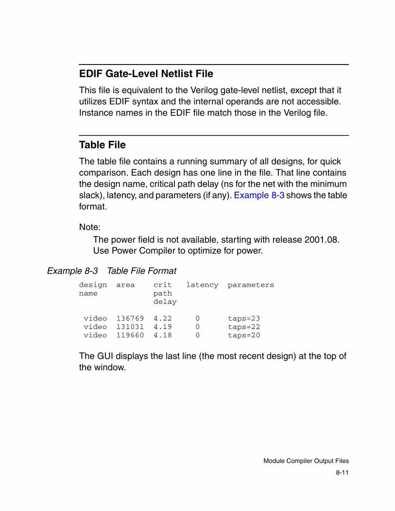
EDIF Gate-Level Netlist File
This file is equivalent to the Verilog gate-level netlist, except that it utilizes EDIF syntax and the internal operands are not accessible. Instance names in the EDIF file match those in the Verilog file.
Table File
The table file contains a running summary of all designs, for quick comparison. Each design has one line in the file. That line contains the design name, critical path delay (ns for the net with the minimum slack), latency, and parameters (if any). Example 8-3 shows the table format.
Note: The power field is not available, starting with release 2001.08. Use Power Compiler to optimize for power.
Example 8-3 Table File Format
design area crit latency parametersname path
delay
video 136769 4.22 0 taps=23 video 131031 4.19 0 taps=22 video 119660 4.18 0 taps=20
The GUI displays the last line (the most recent design) at the top of the window.
8-11
Module Compiler Output Files

Design Compiler Report and Netlist
The Design Compiler Report and netlist files are generated by Design Compiler. See the Design Compiler documentation for details about them.
Naming
Module Compiler allows you to control the naming of nets, wires, and instances. If you do not provide names, Module Compiler creates the names, following certain guidelines. The following sections describe how to control names and, in case you do not provide names, how Module Compiler creates names for you.
Note: The following sections refer to Sim Debug Mode and Use Group Names, which are on the Synthesis menu and the Reports menu, respectively.
Instance Names
You can use instance names to enhance debugging and to guide the floorplanning of soft cells by providing groups of instances with a common prefix. Instance names are in one of the four formats shown in Table 8-3, depending on the status of Sim Debug Mode and Use Group Names.
You can enable Sim Debug Mode from the GUI (Reports menu) or by setting the Module Compiler environment variable dp_debugsim to plus (+). Similarly, you can enable Use Group Names from the GUI (Synthesis menu) or by setting the Module Compiler environment variable dp_longname to plus (+).
8-12
Chapter 8: Analysis and Optimization
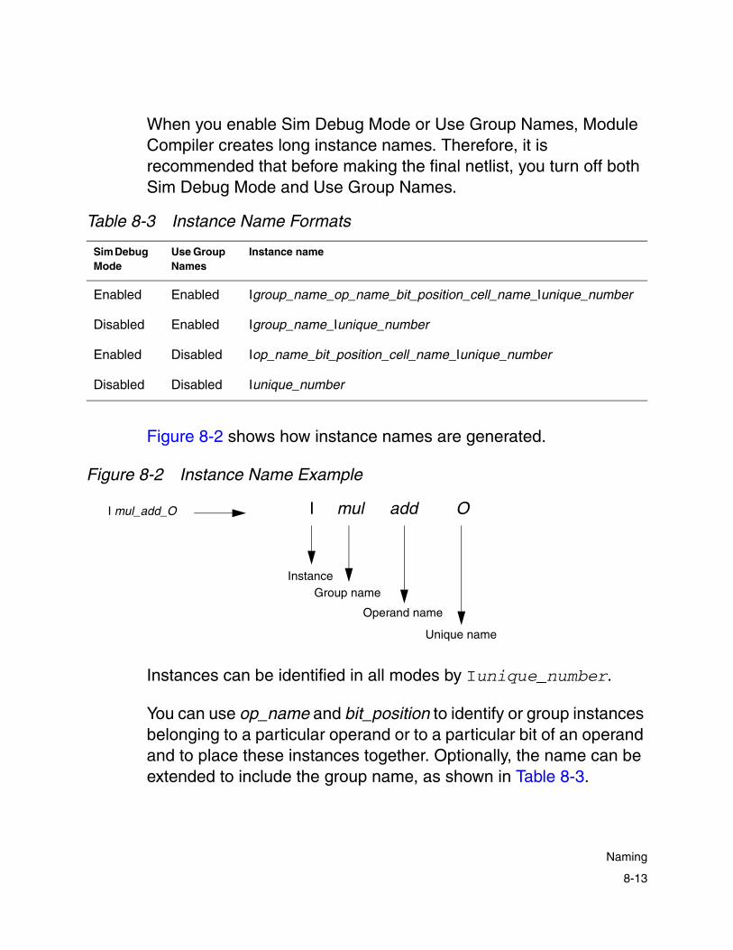
When you enable Sim Debug Mode or Use Group Names, Module Compiler creates long instance names. Therefore, it is recommended that before making the final netlist, you turn off both Sim Debug Mode and Use Group Names.
Figure 8-2 shows how instance names are generated.
Figure 8-2 Instance Name Example
Instances can be identified in all modes by Iunique_number.
You can use op_name and bit_position to identify or group instances belonging to a particular operand or to a particular bit of an operand and to place these instances together. Optionally, the name can be extended to include the group name, as shown in Table 8-3.
Table 8-3 Instance Name Formats
Sim Debug Mode
Use Group Names
Instance name
Enabled Enabled Igroup_name_op_name_bit_position_cell_name_Iunique_number
Disabled Enabled Igroup_name_Iunique_number
Enabled Disabled Iop_name_bit_position_cell_name_Iunique_number
Disabled Disabled Iunique_number
Instance
I mul_add_O
Unique name
Operand name
Group name
O I mul add
8-13
Naming

Using short names (Sim Debug Mode disabled) is recommended when you are preparing your design for place and route.
To generate instance names in lowercase, use the dp_lowercase_inst_name environment variable. Instance names in gate-level netlists begin with a capital letter "I" by default. Module Compiler uses lowercase when you set the dp_lowercase_inst_name variable to plus (+).
Net Names
Net names have formats similar to those of instance names. The formats are shown in Table 8-4.
In Table 8-4, instance_name is an instance name that has been generated with the formats in Table 8-3.
Nets can be identified in all modes by Nunique_number.
Table 8-4 Net Name Formats
Sim Debug Mode
Use Group Names
Instance name
Enabled Enabled NIinstance_name__Nunique_number
Disabled Enabled Ngroup_name__Nunique_number
Enabled Disabled NIinstance_name__Nunique_number
Disabled Disabled Nunique_number
8-14
Chapter 8: Analysis and Optimization
To generate net names in lowercase, use the dp_lowercase_net_name environment variable. Net names in gate-level netlists begin with a capital letter "N" by default. Module Compiler uses lowercase when you set the dp_lowercase_net_name variable to plus (+).
Wire Names
Module Compiler creates unique names for all wires in the design as the hierarchy is flattened and whenever temporary operands are created. In all cases, signals that Module Compiler creates have names that end with “_”. User-defined signal names must not end with “_”.
Specifically, Module Compiler creates new signal names as follows:
• Module outputs
These signals are referred to by a local name. At the end of synthesis, Module Compiler assigns the local named variable to the module output.
The local name is of the formname_integer_
where name is the name of the output as declared and integer is an integer quantity.
• Temporary variables created to compute an expression
The local name is of the formname_integer_
8-15
Naming
where name is the name of the signal on the left side of the statement containing the expression. If the expression is an argument to a function—for example, sat(A+B, ...)—the local name is the first signal argument to the function.
• Wires created inside a function
You refer to these signals by using a local name. The local name is of the formbasename_name_integer_
where name is the name of the wire as declared and integer_ is a unique attachment that is created only if basename_name_ already exists.
basename is created under the following rules:
- Use the name of the function instance, if it is provided according to the function-calling conventions.
- Otherwise, use the name of the first output of the function if it is declared before the wire statement that leads to the creation of the name.
- Otherwise, use the name of the first signal argument to the function.
- Otherwise, use the string temp.
• Function inputs and outputs
All function inputs and outputs are namedbasename_pin_name.
8-16
Chapter 8: Analysis and Optimization

• Temporary variables created at function boundaries to perform conversion between mismatching parameter widths and/or formats
Temporary variables are named basename_paramname_, where basename is determined as described above and paramname is the name of the parameter inside the function.
The naming of temporary variables used as function outputs (and therefore as base names for wires inside a function) can be complicated. However, the generated names are consistent with the above rules.
For instance,
A = fnX(B) + fnY(C)
leads to two function calls: fnX(A_5_, B) and fnY(A_6_, C). The wires declared inside fnX and fnY are named after A_5_ and A_6_ or the root name A, which is the same as the left side of this expression.
Controlling Names
To control all names in Module Compiler, you must provide all functions with instance names. If you do not do this, Module Compiler generates names for you and you lose control of naming.
Example 8-4 shows how function wires and I/Os are named.
Example 8-4 Wire and I/O Names Inside a Function
function func2 (H,I,J);input I,J;output [11] H;wire [11] K=I*J;
8-17
Naming

H=K+J;endfunction
function func1 (Z,X,Y);input X,Y;output Z;wire [11] Q=X*X;wire [11] Q1;func2 myname2(Q1,Y,X);Z=2*Q-Q1;
endfunction
module mod (D,A,B);input [8] A,B;output [11] D;wire [9] E,F;wire [11] G;E=func1(A,B);func1 myname(F,B,A);G=E^F;D=G;
endmodule
Note that func1 in Example 8-4 is called both with and without an instance name from module mod. The following are the available hierarchical names:
mod/A = Amod/B = Bmod/D = Dmod/E = Emod/F = Fmod/G = G
mod/E/X = E_X_ = Amod/E/Y = E_Y_ = Bmod/E/Q = E_Q_ mod/E/Q1 = E_Q1_mod/E/Z = E_Z_ = E
mod/E/myname2/I = E_myname2_I_ = Bmod/E/myname2/J = E_myname2_J_ = Amod/E/myname2/K = E_myname2_K_
8-18
Chapter 8: Analysis and Optimization
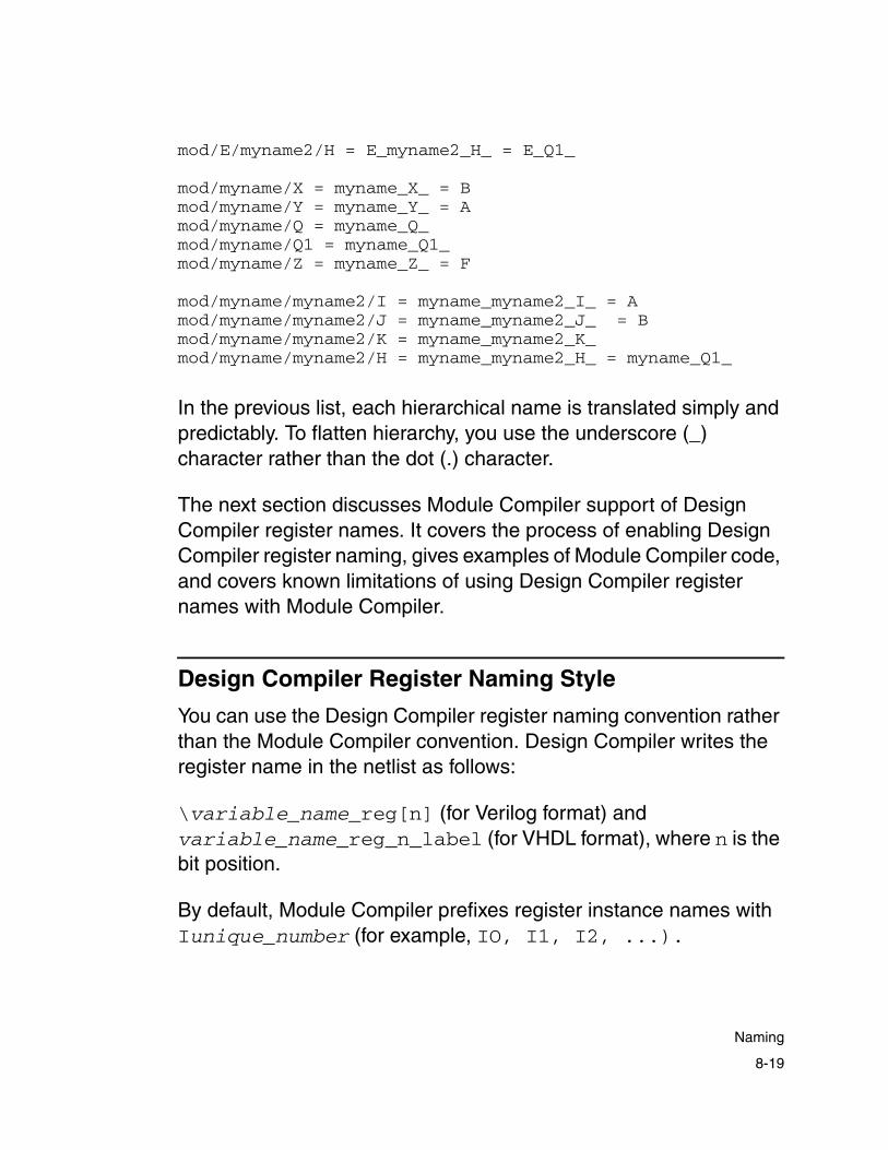
mod/E/myname2/H = E_myname2_H_ = E_Q1_
mod/myname/X = myname_X_ = Bmod/myname/Y = myname_Y_ = Amod/myname/Q = myname_Q_ mod/myname/Q1 = myname_Q1_mod/myname/Z = myname_Z_ = F
mod/myname/myname2/I = myname_myname2_I_ = Amod/myname/myname2/J = myname_myname2_J_ = Bmod/myname/myname2/K = myname_myname2_K_mod/myname/myname2/H = myname_myname2_H_ = myname_Q1_
In the previous list, each hierarchical name is translated simply and predictably. To flatten hierarchy, you use the underscore (_) character rather than the dot (.) character.
The next section discusses Module Compiler support of Design Compiler register names. It covers the process of enabling Design Compiler register naming, gives examples of Module Compiler code, and covers known limitations of using Design Compiler register names with Module Compiler.
Design Compiler Register Naming Style
You can use the Design Compiler register naming convention rather than the Module Compiler convention. Design Compiler writes the register name in the netlist as follows:
\variable_name_reg[n] (for Verilog format) and variable_name_reg_n_label (for VHDL format), where n is the bit position.
By default, Module Compiler prefixes register instance names with Iunique_number (for example, IO, I1, I2, ...).
8-19
Naming
This naming scheme can make it difficult to differentiate registers or other gates from their instance names. By using the Design Compiler register naming convention, you might be able to improve your formal verification flow, because you can more easily identify match points between the RTL and the gate-level netlist.
You enable the Design Compiler register naming convention described in the next section, “Enabling Design Compiler Register Naming Style.”
Enabling Design Compiler Register Naming Style
To enable Design Compiler register naming support, you modify the mc.env file. Using a text editor such as vi or EMACS, add the following line to the mc.env file:
dp_dc_style_reg_name +
Alternatively, you can enter at the UNIX prompt
% mcenv dp_dc_style_reg_name +
This command enters the variable and its settings into the mc.env file. The default for dp_dc_style_reg_name is minus (-), meaning that Design Compiler register naming will not be used.
Examples
In each of the following examples, you are first shown the Module Compiler Language sample, followed by the resulting behavioral RTL file and gate-level netlist samples generated by Module Compiler with register naming (shown in Verilog and VHDL format).
8-20
Chapter 8: Analysis and Optimization
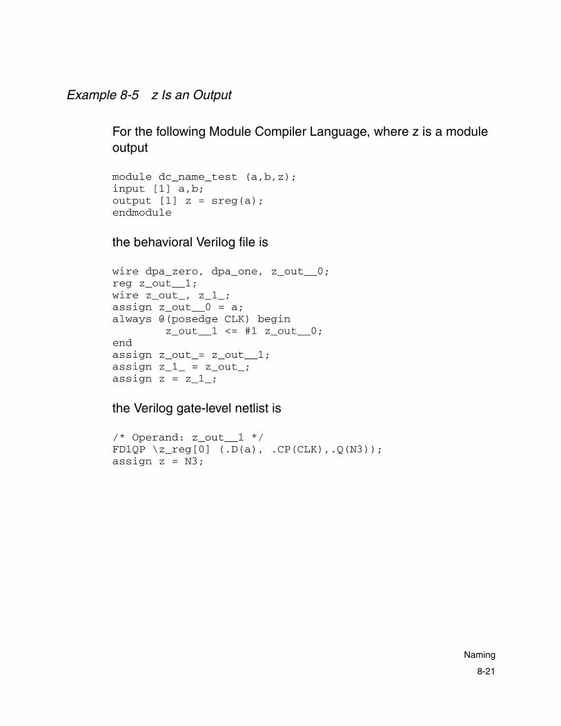
Example 8-5 z Is an Output
For the following Module Compiler Language, where z is a module output
module dc_name_test (a,b,z);input [1] a,b;output [1] z = sreg(a);endmodule
the behavioral Verilog file is
wire dpa_zero, dpa_one, z_out__0;reg z_out__1;wire z_out_, z_1_;assign z_out__0 = a;always @(posedge CLK) begin z_out__1 <= #1 z_out__0;endassign z_out_= z_out__1;assign z_1_ = z_out_;assign z = z_1_;
the Verilog gate-level netlist is
/* Operand: z_out__1 */FD1QP \z_reg[0] (.D(a), .CP(CLK),.Q(N3));assign z = N3;
8-21
Naming

the behavioral VHDL file is
z_out_0 <= a;process(CLK)begin if (CLK’event and CLK = '1') then z_out_1 <= z_out_0 after 1 ns; end if;end process; z_out <= z_out_1;
z_1_dpa <= z_out;
z <= z_1_dpa;
the VHDL gate-level netlist is
z_reg_0_label : FD1QP port map( D => a, CP => CLK, Q => N3 ); z <= N3;
Example 8-6 z Is Not an Output
For the following Module Compiler Language, where z is not a module output:
module dc_name_test (a,b,qout);input [1] a,b;wire [1] z = sreg(a);output [1] qout =z;endmodule
8-22
Chapter 8: Analysis and Optimization

the behavioral Verilog file is
wire dpa_zero, dpa_one, z_out__0;reg z_out__1;wire z_out_, z, qout_2_;assign z_out__0 = a;always @(posedge CLK) begin z_out__1 <= #1 z_out__0;endassign z_out_= z_out__1;assign z = z_out_;assign qout_2_= (z);assign qout = qout_2_;
the Verilog gate-level netlist is
/* Operand: z_out__1 */FD1QP \z_reg[0] ( .D(a), .CP(CLK), .Q(N3) );assign qout = N3;
the behavioral VHDL file is
FUNCTION dpa_extx(ARG: STD_LOGIC_VECTOR; SIZE: INTEGER) returnSTD_LOGIC_VECTOR is constant msb: INTEGER := dpa_min(ARG'length, SIZE) - 1; subtype rtype is STD_LOGIC_VECTOR (SIZE-1 downto 0); variable new_bounds : STD_LOGIC_VECTOR (ARG'length-1 downto 0); variable result: rtype;begin new_bounds := ARG; result := rtype'(others => '0'); result(msb downto 0) := new_bounds(msb downto 0); return result;end;
FUNCTION dpa_getLSB(ARG: STD_LOGIC_VECTOR) return STD_LOGIC is constant lsb: INTEGER := ARG'low(1);beginreturn ARG(lsb);end;
8-23
Naming

z_out_0 <= a;process(CLK)begin if (CLK'event and CLK = '1') then z_out_1 <= z_out_0 after 1 ns; end if;end process; z_out <= z_out_1;
z <= z_out;
qout_2_dpa <= dpa_getLSB(dpa_extx(conv_std_logic_vector(z, 1),1));
qout <= qout_2_dpa;
the VHDL gate-level netlist is
-- Operand: z_out_1 z_reg_0_label : FD1QP port map( D => a, CP => CLK, Q => N3 ); qout <= N3;
Example 8-7 z Is a Bus
For the following Module Compiler Language, where z is a bus:
module dc_name_test (a,b,z);input [10] a,b;output [10] z = sreg(a);endmodule
8-24
Chapter 8: Analysis and Optimization

the behavioral Verilog file is
wire [10] z_out__0;reg [10] z_out__1;wire [10] z_out_, z_1_;assign z_out__0 = a[10];always @(posedge CLK) begin z_out__1 <= #1 z_out__0;endassign z_out_= z_out__1;assign z_1_ = z_out_[10];assign z = z_1_[10];
the Verilog gate-level netlist is
FD1QP \z_reg[0] ( .D(a[0]), .CP(CLK), .Q(N3) );FD1QP \z_reg[1] ( .D(a[1]), .CP(CLK), .Q(N4) );FD1QP \z_reg[2] ( .D(a[2]), .CP(CLK), .Q(N5) );FD1QP \z_reg[3] ( .D(a[3]), .CP(CLK), .Q(N6) );FD1QP \z_reg[4] ( .D(a[4]), .CP(CLK), .Q(N7) );FD1QP \z_reg[5] ( .D(a[5]), .CP(CLK), .Q(N8) );FD1QP \z_reg[6] ( .D(a[6]), .CP(CLK), .Q(N9) );FD1QP \z_reg[7] ( .D(a[7]), .CP(CLK), .Q(N10) );FD1QP \z_reg[8] ( .D(a[8]), .CP(CLK), .Q(N11) );FD1QP \z_reg[9] ( .D(a[9]), .CP(CLK), .Q(N12) );assign z[0] = N3;
the behavioral VHDL file is
z_out_0 <= a(9 downto 0);process(CLK)begin if (CLK'event and CLK = '1') then z_out_1 <= z_out_0 after 1 ns; end if;end process; z_out <= z_out_1;
z_1_dpa <= z_out(9 downto 0);
z <= z_1_dpa(9 downto 0);
8-25
Naming

the VHDL gate-level netlist is
-- Operand: z_out_1 z_reg_0_label : FD1QP port map( D => a(0), CP => CLK, Q => N3 ); z_reg_1_label : FD1QP port map( D => a(1), CP => CLK, Q => N4 ); z_reg_2_label : FD1QP port map( D => a(2), CP => CLK, Q => N5 ); z_reg_3_label : FD1QP port map( D => a(3), CP => CLK, Q => N6 ); z_reg_4_label : FD1QP port map( D => a(4), CP => CLK, Q => N7 ); z_reg_5_label : FD1QP port map( D => a(5), CP => CLK, Q => N8 ); z_reg_6_label : FD1QP port map( D => a(6), CP => CLK, Q => N9 ); z_reg_7_label : FD1QP port map( D => a(7), CP => CLK, Q => N10 ); z_reg_8_label : FD1QP port map( D => a(8), CP => CLK, Q => N11 ); z_reg_9_label : FD1QP port map( D => a(9), CP => CLK, Q => N12 ); z(0) <= N3; z(1) <= N4; z(2) <= N5; z(3) <= N6; z(4) <= N7; z(5) <= N8; z(6) <= N9; z(7) <= N10; z(8) <= N11; z(9) <= N12;
8-26
Chapter 8: Analysis and Optimization

Example 8-8 z Has More Than One Stage
For the following Module Compiler Language, where z has more than one stage:
module dc_name_test (a,b,z);input [1] a,b;output [1] z = sreg(a,4);endmodule
the behavioral Verilog file is
reg z_out__1, z_out__2, z_out__3, z_out__4;wire z_out_, z_1_;assign z_out__0 = a;always @(posedge CLK) begin z_out__4 <= #1 z_out__3; z_out__3 <= #1 z_out__2; z_out__2 <= #1 z_out__1; z_out__1 <= #1 z_out__0;endassign z_out_= z_out__4;assign z_1_ = z_out_;assign z = z_1_;
the Verilog gate-level netlist is
/* Operand: z_out__1 */FD1QP \z__1_reg[0] ( .D(a), .CP(CLK), .Q(N3) );/* Operand: z_out__2 */FD1QP \z__2_reg[0] ( .D(N3), .CP(CLK), .Q(N4) );/* Operand: z_out__3 */FD1QP \z__3_reg[0] ( .D(N4), .CP(CLK), .Q(N5) );
/* Operand: z_out__4 */FD1QP \z__4_reg[0] ( .D(N5), .CP(CLK), .Q(N6) );assign z = N6;endmodule
8-27
Naming

the behavioral VHDL file is
z_out_0 <= a;process(CLK)begin if (CLK'event and CLK = '1') then z_out_4 <= z_out_3 after 1 ns; z_out_3 <= z_out_2 after 1 ns; z_out_2 <= z_out_1 after 1 ns; z_out_1 <= z_out_0 after 1 ns; end if;end process; z_out <= z_out_4;
z_1_dpa <= z_out;
z <= z_1_dpa;
the VHDL gate-level netlist is
-- Operand: z_out_1 z_1_reg_0_label : FD1QP port map( D => a, CP => CLK, Q => N3 );
-- Operand: z_out_2 z_2_reg_0_label : FD1QP port map( D => N3, CP => CLK, Q => N4 );
-- Operand: z_out_3 z_3_reg_0_label : FD1QP port map( D => N4, CP => CLK, Q => N5 );
-- Operand: z_out_4 z_4_reg_0_label : FD1QP port map( D => N5, CP => CLK, Q => N6 ); z <= N6;
8-28
Chapter 8: Analysis and Optimization
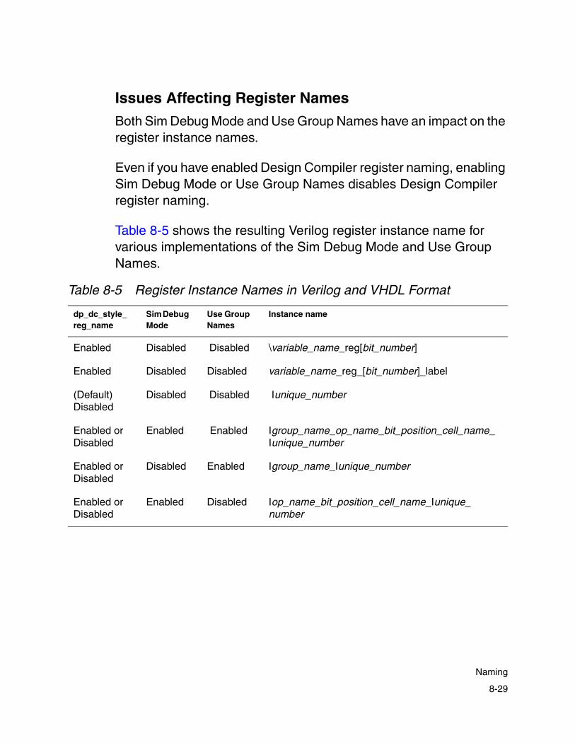
Issues Affecting Register Names
Both Sim Debug Mode and Use Group Names have an impact on the register instance names.
Even if you have enabled Design Compiler register naming, enabling Sim Debug Mode or Use Group Names disables Design Compiler register naming.
Table 8-5 shows the resulting Verilog register instance name for various implementations of the Sim Debug Mode and Use Group Names.
Table 8-5 Register Instance Names in Verilog and VHDL Format
dp_dc_style_reg_name
Sim Debug Mode
Use Group Names
Instance name
Enabled Disabled Disabled \variable_name_reg[bit_number]
Enabled Disabled Disabled variable_name_reg_[bit_number]_label
(Default) Disabled
Disabled Disabled Iunique_number
Enabled or Disabled
Enabled Enabled Igroup_name_op_name_bit_position_cell_name_Iunique_number
Enabled or Disabled
Disabled Enabled Igroup_name_Iunique_number
Enabled or Disabled
Enabled Disabled Iop_name_bit_position_cell_name_Iunique_number
8-29
Naming

Pipelining
The instance name of the registers coming from the pipeline portion of the design are named for Verilog and VHDL as follows:
If dp_dc_style_reg_name is plus (+) and both dp_debugsim (Sim Debug Mode) and dp_longname (Use Group Names) are minus (-), the instance name is Punique_number_stagestage_number. This convention is seen in Example 8-9.
Example 8-9 Pipelining Example
//Module Compiler Languagemodule dc_name_test (a,b,z);directive(delay = 2000, pipeline= "on");input [4] a,b;
output [8] z = a*b;endmodule
//A Portion of Verilog RTLassign z_1_= (a[4]*b[4]);
reg [8]__z__1,__z__2,__z__3,__z__4,__z__5,__z__6,__z__7;
wire [8] __z__0;assign __z__0 = z_1_[8];always @(posedge CLK) begin __z__7 <= #1 __z__6; __z__6 <= #1 __z__5; __z__5 <= #1 __z__4; __z__4 <= #1 __z__3; __z__3 <= #1 __z__2; __z__2 <= #1 __z__1; __z__1 <= #1 __z__0;endassign z= __z__7;
8-30
Chapter 8: Analysis and Optimization

//A Portion of Verilog Gate-Level NetlistFD1QP P0_stage1 ( .D(N239), .CP(CLK), .Q(N33) );FD1Q P1_stage1 ( .D(N236), .CP(CLK), .Q(N249) );FD1Q P2_stage1 ( .D(N517), .CP(CLK), .Q(N250) );FA1AP I29( .A(N33), .B(N249), .CI(N250), .S(N31), .CO(N32));HA1 I30 ( .A(N515), .B(N243), .S(N520), .CO(N521) );FD1QP P3_stage1 ( .D(N240), .CP(CLK), .Q(N40) );FD1Q P4_stage1 ( .D(N519), .CP(CLK), .Q(N253) );FD1Q P5_stage1 ( .D(N520), .CP(CLK), .Q(N254) );FD1Q P8_stage1 ( .D(N521), .CP(CLK), .Q(N256) );
//A Portion of VHDL RTLFUNCTION dpa_extx(ARG: STD_LOGIC_VECTOR; SIZE: INTEGER) return STD_LOGIC_VECTOR is constant msb: INTEGER := dpa_min(ARG'length, SIZE) - 1; subtype rtype is STD_LOGIC_VECTOR (SIZE-1 downto 0); variable new_bounds : STD_LOGIC_VECTOR (ARG'length-1 downto 0); variable result: rtype;begin new_bounds := ARG; result := rtype'(others => '0'); result(msb downto 0) := new_bounds(msb downto 0); return result;end;
z_1_dpa <= (dpa_extx(dpa_extx(a(3 downto 0),8)*dpa_extx(b(3 downto 0),8),8));
B1_blk_dpa : blocksignal dpa_z_dpa_0 : std_logic_vector(7 downto 0);signal dpa_z_dpa_1, dpa_z_dpa_2, dpa_z_dpa_3, dpa_z_dpa_4, dpa_z_dpa_5, dpa_z_dpa_6, dpa_z_dpa_7 : std_logic_vector(7 downto 0);begindpa_z_dpa_0 <= z_1_dpa(7 downto 0);process(CLK)begin if (CLK'event and CLK = '1') then dpa_z_dpa_7 <= dpa_z_dpa_6 after 1 ns; dpa_z_dpa_6 <= dpa_z_dpa_5 after 1 ns; dpa_z_dpa_5 <= dpa_z_dpa_4 after 1 ns; dpa_z_dpa_4 <= dpa_z_dpa_3 after 1 ns; dpa_z_dpa_3 <= dpa_z_dpa_2 after 1 ns;
8-31
Naming

dpa_z_dpa_2 <= dpa_z_dpa_1 after 1 ns; dpa_z_dpa_1 <= dpa_z_dpa_0 after 1 ns; end if;end process; z <= dpa_z_dpa_7;end block;
//A Portion of VHDL Gate-Level NetlistP0_stage1 : FD1QP port map( D => N239, CP => CLK, Q => N33 ); P1_stage1 : FD1Q port map( D => N236, CP => CLK, Q => N249 ); P2_stage1 : FD1Q port map( D => N517, CP => CLK, Q => N250 ); P3_stage1 : FD1QP port map( D => N240, CP => CLK, Q => N40 ); P4_stage1 : FD1Q port map( D => N519, CP => CLK, Q => N253 ); P5_stage1 : FD1Q port map( D => N520, CP => CLK, Q => N254 ); port map( A => N40, B => N253, CI => N254, S =>N38, CO => N39 );
Known Limitations
The following are known limitations for Design Compiler register naming support:
• If the design has more than one stage, the instance name gets a double underscore (__).
Example 8-10 Design With More Than One Stage
module dc_name_test (a,b,z);input [1] a,b;output [1] z = sreg(a,4);endmodule
8-32
Chapter 8: Analysis and Optimization

From Example 8-10, the netlist appears as follows:
/* Operand: z_out__1 */FD1QP \z__1_reg[0] ( .D(a), .CP(CLK), .Q(N3) );
/* Operand: z_out__2 */FD1QP \z__2_reg[0] ( .D(N3), .CP(CLK), .Q(N4) );
/* Operand: z_out__3 */FD1QP \z__3_reg[0] ( .D(N4), .CP(CLK), .Q(N5) );
/* Operand: z_out__4 */FD1QP \z__4_reg[0] ( .D(N5), .CP(CLK), .Q(N6) );
• If dp_dc_style_reg_name is plus (+) and dp_debugsim (Sim Debug Mode) and dp_longname (Use Group Names) are both minus (-), you do not get Design Compiler-style naming in the following cases:
- If the design has the delstate attribute, the register name of this portion of the design is Iunique_number.
- If the design has an instantiated register cell, the instance name of that register is Iunique_number.
- If dp_dc_style_reg_name is plus (+) and the register drives the output port of the pseudocell (see Figure 8-3), Module Compiler writes the flip-flop in the netlist with the Design Compiler naming convention after flattening the pseudocell.
8-33
Naming

Figure 8-3 Enable Flip-Flop Pseudocell
However, if the flip-flop does not drive the output port of the pseudocell, Module Compiler writes the flip-flop in the netlist without using the Design Compiler register naming convention and the instance name is Iunique_number. Currently there is no such pseudocell as one in which the register is not driving the output.
• If a pseudocell has more than one register, the register instance name of these registers is Iunique_number. Currently, there is no such pseudocell as one with more than one register.
Verilog or VHDL Simulation
Module Compiler provides behavioral as well as gate-level (structural) simulation files. Use behavioral simulation as a quick way of verifying functionality and gate-level simulation for more-detailed timing and functionality verification.
pseudocell
D flip-flop
MU
X
out
in
LD
8-34
Chapter 8: Analysis and Optimization

Behavioral Verification
You can simulate your design without looking at the behavioral simulation file. You can access all internal wires by naming objects according to the rules in the “Naming” section of this chapter.
In some cases, Module Compiler creates additional operands that appear in the behavioral model. You can ignore them, because they do not cause user-defined operands to change meaning.
A few functions are too complex to be accurately modeled behaviorally. Be careful when simulating designs with carry-save operands, pipelining, or pipeline loaning. Such functions might not be modeled accurately and can lead to mismatching between logic and behavioral models. All other operands in the design, including the top-level outputs, will be correct.
To aid in debugging, relevant sections of the Module Compiler Language file are placed as comments before the corresponding behavioral code. This helps you understand the behavior of the Module Compiler functions and how Module Compiler resolves replication and parameterization.
Note: Your comments in the Module Compiler Language file are not passed on to these behavioral files.
When Module Compiler compiles RAMs and inserts them into the design, the RAM cell instantiated in the behavioral model might not match that in the gate-level netlist. However, the behavior of the RAM is equivalent. This mismatch happens when the optimizer swaps the original RAM for another, equivalent and better RAM.
8-35
Verilog or VHDL Simulation

Gate-Level Simulation
For simulation, input, output, and most internal signals are accessible in the Verilog gate-level netlist. The internal signals—those you defined that are not inputs or outputs—are useful during detailed timing and functional debugging.
The instance and net names in this file are affected by both the Sim Debug Mode option and the Use Group Names option. See “Naming” on page 8-12 for a full description of naming in Module Compiler.
Note: You must set the Sim Debug Mode option to examine any wires in the design other than the module inputs and outputs.
The instances in this file are broken into groups that are annotated with comments indicating the current group and operand.
VHDL Support
The following section presents information for VHDL users of Module Compiler. It includes information about the standard and technology libraries used and the elements of the VHDL description.
Standard Libraries
For the gate-level description of a design, Module Compiler uses the following IEEE standard library:
std_logic_1164
8-36
Chapter 8: Analysis and Optimization

For the behavioral VHDL description of a design, Module Compiler uses the following IEEE standard libraries:
• std_logic_1164
• std_logic_arith
• std_logic_misc
• std_logic_unsigned
Technology Library
Gate-level output uses the components defined in the technology library. Also, if you have instantiated any cell in your Module Compiler Language description, the behavioral description includes that instantiation.
Module Compiler declares all the used components in the architecture declaration section.
By default, Module Compiler does not specify the logical library name in the VHDL output. Do the following if you want to declare the logical library name in the VHDL output,
• Create a file containing your declarations
• Set the Module Compiler environment variable
dp_vhdl_prefix_file_name
to the name of this file, using the mcenv command.
8-37
Verilog or VHDL Simulation

For example, if you use technology library lca500k.db and you want to declare logical library lca500k in your VHDL output, you should write the following declarations in a file, say log_lib.vhd:
library lca500k;use lca500k.components.all;
Then, set the Module Compiler environment variable to the name of this file by entering the following at the UNIX prompt:
% mcenv dp_vhdl_prefix_file_name log_lib.vhd
If you want to read the VHDL output into dc_shell, specify the target library and link it as the technology library.
Elements of the VHDL Description
Module Compiler arranges both the gate-level and the behavioral description of the design in the same way. An inner design entity defines the core design, and a wrapper entity acts as an interface.
The top-level entity name is the same as the module name you define in the .mcl file. The core entity name is
dpa_entity_module_name
where
module_name
is the name of the module you define in the .mcl file.
Module Compiler instantiates this core entity in the wrapper entity with the instance name
dpa_inst_module_name
8-38
Chapter 8: Analysis and Optimization
In the core design entity, every signal/port is a vector. The core entity has ports of the same size and type you specify in the Module Compiler Language description.
The wrapper entity defines all unit-length vector ports as scalars. The names of the ports are the same as those of the core entity (the same as the port names in the Module Compiler Language description). Module Compiler does not modify the names of the signals you use in the .mcl file.
The data types Module Compiler uses to write out the behavioral output are as follows:
• Constant of type integer
• Variable of type std_logic_vector and sub_type of std_logic_vector
• Signals of type std_logic_vector and std_logic
Data types used in the gate-level output are signals of type std_logic_vector and std_logic.
Entity Generation Disabling
To disable entity generation and to generate only the architecture of the design, enter the following at the UNIX prompt:
% mcenv dp_write_vhdl_entity -
By default, the value of the environment variable dp_write_vhdl_entity is set to +, which generates an entity. Setting this variable to minus (–) disables entity generation.
8-39
Verilog or VHDL Simulation
Internally Defined Functions
In the behavioral description, the architecture body of the design defines the functions dpa_extx, dpa_sxtx, dpa_cond, dpa_min, and dpa_max.
These are reserved function names. To avoid naming conflicts, do not use these function names in your design.
Configurations
Module Compiler does not write out any configurations in your VHDL output. You are free to define your configurations based on your needs.
Getting More-Detailed Design Report Information
You can get more-detailed design information through user-defined group reports and user-defined critical paths.
User-Defined Group Reports
Use hierarchical groups and the custom group reporting mechanism to get more-detailed information on your design. The high-level groups can give you a good idea of the general behavior of the design, whereas lower-level groups are useful for debugging.
In Example 8-11, the video processor is broken into three top-level groups: matrix, hide, and fir. Each group has three subgroups: Y, U, and V. By default, Module Compiler provides data for the complete matrix, hide, and fir groups. You can request information for all groups related to Y by calling showgroup *.Y.
8-40
Chapter 8: Analysis and Optimization

Example 8-11 Requesting More-Detailed Report Informationmodule video (taps,replicate(integer i=0; i<taps; i=i+1) {YC{i},}R,G,B,Y,U,V);integer taps = 23;directive (pipeline="on",delay=9999999);input signed [8] repl(i, taps, ",") {YC{i}};input [8] R,G,B;output [21] Y,U,V;buffer(R,2); buffer(G,2); buffer(B,2);wire signed [16] U1,U_int,V1,V_int;wire [16] Y1,Y_int;directive (group="matrix.Y"); Y_int=R*89+G*138+B*47;directive (group="matrix.U"); U_int=0-33*R+144*G+88*B;directive (group="matrix.V"); V_int=53*R-91*G+102*B;directive (group="hide.Y"); Y1=hidelat(Y_int);directive (group="hide.U"); U1=hidelat(U_int);directive (group="hide.V"); V1=hidelat(V_int);wire unsigned [10] YSR,repl(i, taps+1, ",") {Y_{i}};wire signed [10] USR,repl(i, taps+1, ",") {U_{i}};wire signed [10] VSR,repl(i, taps+1, ",") {V_{i}};directive (group="fir.Y");YSR=sreg(Y1[15:6],taps,repl(i, taps+1, ",") {Y_{i}});directive (group="fir.U");USR=sreg(U1[15:6],taps,repl(i, taps+1, ",") {U_{i}});directive (group="fir.V");VSR=sreg(V1[15:6],taps,repl(i, taps+1, ",") {V_{i}});directive (group="fir.Y");Y=replicate (i=0; i<taps; i=i+1) {Y_{i+1}*YC{i}+} 0;directive (group="fir.U");U=replicate (i=0; i<taps; i=i+1) {U_{i+1}*YC{i}+} 0;directive (group="fir.V");V=replicate (i=0; i<taps; i=i+1) {V_{i+1}*YC{i}+} 0;showgroup("*.Y"); showgroup("*.U"); showgroup("*.V");showgroup("fir.*");showgroup("matrix.*");endmodule
The previous code produces the group information in Example 8-12. The first two sections are generated automatically by Module Compiler.
Note: The Power field is not available, starting with release 2001.08. Use Power Compiler to optimize for power.
8-41
Getting More-Detailed Design Report Information
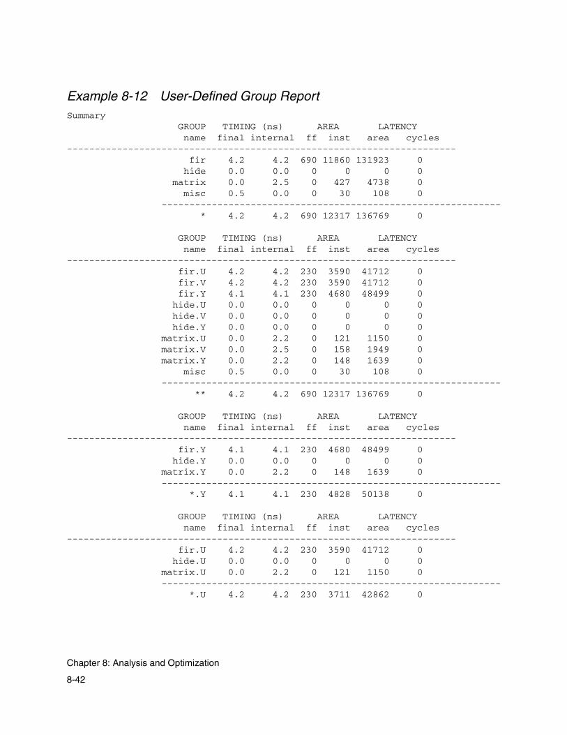
Example 8-12 User-Defined Group ReportSummary GROUP TIMING (ns) AREA LATENCY name final internal ff inst area cycles---------------------------------------------------------------------- fir 4.2 4.2 690 11860 131923 0 hide 0.0 0.0 0 0 0 0 matrix 0.0 2.5 0 427 4738 0 misc 0.5 0.0 0 30 108 0 ------------------------------------------------------------- * 4.2 4.2 690 12317 136769 0
GROUP TIMING (ns) AREA LATENCY name final internal ff inst area cycles---------------------------------------------------------------------- fir.U 4.2 4.2 230 3590 41712 0 fir.V 4.2 4.2 230 3590 41712 0 fir.Y 4.1 4.1 230 4680 48499 0 hide.U 0.0 0.0 0 0 0 0 hide.V 0.0 0.0 0 0 0 0 hide.Y 0.0 0.0 0 0 0 0 matrix.U 0.0 2.2 0 121 1150 0 matrix.V 0.0 2.5 0 158 1949 0 matrix.Y 0.0 2.2 0 148 1639 0 misc 0.5 0.0 0 30 108 0 ------------------------------------------------------------- ** 4.2 4.2 690 12317 136769 0
GROUP TIMING (ns) AREA LATENCY name final internal ff inst area cycles---------------------------------------------------------------------- fir.Y 4.1 4.1 230 4680 48499 0 hide.Y 0.0 0.0 0 0 0 0 matrix.Y 0.0 2.2 0 148 1639 0 ------------------------------------------------------------- *.Y 4.1 4.1 230 4828 50138 0
GROUP TIMING (ns) AREA LATENCY name final internal ff inst area cycles---------------------------------------------------------------------- fir.U 4.2 4.2 230 3590 41712 0 hide.U 0.0 0.0 0 0 0 0 matrix.U 0.0 2.2 0 121 1150 0 ------------------------------------------------------------- *.U 4.2 4.2 230 3711 42862 0
8-42
Chapter 8: Analysis and Optimization
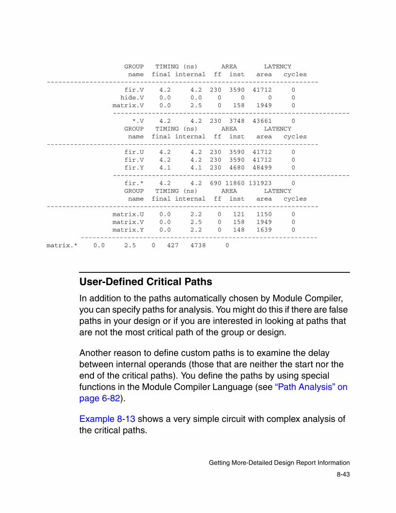
GROUP TIMING (ns) AREA LATENCY name final internal ff inst area cycles---------------------------------------------------------------------- fir.V 4.2 4.2 230 3590 41712 0 hide.V 0.0 0.0 0 0 0 0 matrix.V 0.0 2.5 0 158 1949 0 ------------------------------------------------------------- *.V 4.2 4.2 230 3748 43661 0 GROUP TIMING (ns) AREA LATENCY name final internal ff inst area cycles---------------------------------------------------------------------- fir.U 4.2 4.2 230 3590 41712 0 fir.V 4.2 4.2 230 3590 41712 0 fir.Y 4.1 4.1 230 4680 48499 0 ------------------------------------------------------------- fir.* 4.2 4.2 690 11860 131923 0 GROUP TIMING (ns) AREA LATENCY name final internal ff inst area cycles---------------------------------------------------------------------- matrix.U 0.0 2.2 0 121 1150 0 matrix.V 0.0 2.5 0 158 1949 0 matrix.Y 0.0 2.2 0 148 1639 0 ------------------------------------------------------------- matrix.* 0.0 2.5 0 427 4738 0
User-Defined Critical Paths
In addition to the paths automatically chosen by Module Compiler, you can specify paths for analysis. You might do this if there are false paths in your design or if you are interested in looking at paths that are not the most critical path of the group or design.
Another reason to define custom paths is to examine the delay between internal operands (those that are neither the start nor the end of the critical paths). You define the paths by using special functions in the Module Compiler Language (see “Path Analysis” on page 6-82).
Example 8-13 shows a very simple circuit with complex analysis of the critical paths.
8-43
Getting More-Detailed Design Report Information
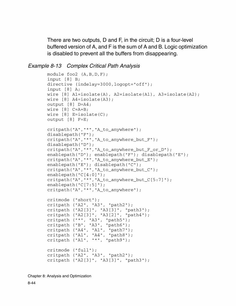
There are two outputs, D and F, in the circuit; D is a four-level buffered version of A, and F is the sum of A and B. Logic optimization is disabled to prevent all the buffers from disappearing.
Example 8-13 Complex Critical Path Analysis
module foo2 (A,B,D,F);input [8] B;directive (indelay=3000,logopt="off");input [8] A;wire [8] A1=isolate(A), A2=isolate(A1), A3=isolate(A2); wire [8] A4=isolate(A3);output [8] D=A4;wire [8] C=A+B;wire [8] E=isolate(C);output [8] F=E;
critpath("A","*","A_to_anywhere");disablepath("F");critpath("A","*","A_to_anywhere_but_F");disablepath("D");critpath("A","*","A_to_anywhere_but_F_or_D");enablepath("D"); enablepath("F"); disablepath("E");critpath("A","*","A_to_anywhere_but_E");enablepath("E"); disablepath("C");critpath("A","*","A_to_anywhere_but_C");enablepath("C[4:0]");critpath("A","*","A_to_anywhere_but_C[5:7]");enablepath("C[7:5]");critpath("A","*","A_to_anywhere");
critmode ("short");critpath ("A2", "A3", "path2");critpath ("A2[3]", "A3[3]", "path3");critpath ("A2[3]", "A3[2]", "path4");critpath ("*", "A3", "path5");critpath ("B", "A3", "path6");critpath ("A4", "A1", "path7");critpath ("A1", "A4", "path8");critpath ("A1", "*", "path9");
critmode ("full");critpath ("A2", "A3", "path2");critpath ("A2[3]", "A3[3]", "path3");
8-44
Chapter 8: Analysis and Optimization

critpath ("A2[3]", "A3[2]", "path4");critpath ("*", "A3", "path5");critpath ("B", "A3", "path6");critpath ("A4", "A1", "path7");critpath ("A1", "A4", "path8");critpath ("A1", "*", "path9");endmodule
The results for Example 8-13 are shown in Example 8-14. The critical path for the design goes from A through the adder to F. When F is deactivated, the next-most-critical path is to D. When F and D are disabled, there are no paths.
8-45
Getting More-Detailed Design Report Information

Example 8-14 Complex Critical Path Analysis OutputUser-Defined Critical Paths------------------------------------------------------------------------------
Critical Path 'A_to_anywhere': from A to *. Endpoint: F[7].critical pin -> critical net delta delay rise fall load gload pins setup: 0.00 8.44 8.37 8.44 A -> E_7_buf1a2_49_Y: 0.76 8.44 8.37 8.44 12.5 10.0 2 CI -> C_7_fa1b1_41_S: 0.61 7.69 7.69 7.69 3.3 0.8 2 CI -> C_6_fa2a1_40_CO: 0.50 7.08 7.08 7.05 7.6 5.1 2 CI -> C_5_fa1b1_39_CO: 0.57 6.58 6.51 6.58 7.9 5.4 2 CI -> C_4_fa2a1_38_CO: 0.50 6.01 6.01 6.00 7.6 5.1 2 CI -> C_3_fa1b1_37_CO: 0.56 5.51 5.46 5.51 7.9 5.4 2 CI -> C_2_fa2a1_36_CO: 0.51 4.95 4.94 4.95 7.6 5.1 2 CI -> C_1_fa1b1_35_CO: 0.54 4.44 4.41 4.44 7.9 5.4 2 B -> C_0_fa2a1_34_CO: 0.90 3.90 3.87 3.90 7.6 5.1 2 A[0]: 3.00 3.00 3.00 3.00 9.8 4.8 3
Deactivating path through F
Critical Path 'A_to_anywhere_but_F': from A to *. Endpoint: D[0].critical pin -> critical net delta delay rise fall load gload pins setup: 0.00 5.50 5.23 5.50 A -> A4_0_buf1a2_26_Y: 0.75 5.50 5.23 5.50 12.5 10.0 2 A -> A3_0_buf1a2_18_Y: 0.58 4.75 4.54 4.75 3.3 0.8 2 A -> A2_0_buf1a2_10_Y: 0.58 4.16 4.03 4.16 3.3 0.8 2 A -> A1_0_buf1a2_2_Y: 0.58 3.58 3.52 3.58 3.3 0.8 2 A[0]: 3.00 3.00 3.00 3.00 9.8 4.8 3
Deactivating path through D
Critical Path 'A_to_anywhere_but_F_or_D': from A to *.No Path found!
Reactivating path through D
Reactivating path through F
Deactivating path through E
Critical Path 'A_to_anywhere_but_E': from A to *. Endpoint: D[0].critical pin -> critical net delta delay rise fall load gload pins setup: 0.00 5.50 5.23 5.50 A -> A4_0_buf1a2_26_Y: 0.75 5.50 5.23 5.50 12.5 10.0 2 A -> A3_0_buf1a2_18_Y: 0.58 4.75 4.54 4.75 3.3 0.8 2 A -> A2_0_buf1a2_10_Y: 0.58 4.16 4.03 4.16 3.3 0.8 2 A -> A1_0_buf1a2_2_Y: 0.58 3.58 3.52 3.58 3.3 0.8 2 A[0]: 3.00 3.00 3.00 3.00 9.8 4.8 3
8-46
Chapter 8: Analysis and Optimization

Reactivating path through E
Deactivating path through C
Critical Path 'A_to_anywhere_but_C': from A to *. Endpoint: D[0].critical pin -> critical net delta delay rise fall load gload pins setup: 0.00 5.50 5.23 5.50 A -> A4_0_buf1a2_26_Y: 0.75 5.50 5.23 5.50 12.5 10.0 2 A -> A3_0_buf1a2_18_Y: 0.58 4.75 4.54 4.75 3.3 0.8 2 A -> A2_0_buf1a2_10_Y: 0.58 4.16 4.03 4.16 3.3 0.8 2 A -> A1_0_buf1a2_2_Y: 0.58 3.58 3.52 3.58 3.3 0.8 2 A[0]: 3.00 3.00 3.00 3.00 9.8 4.8 3
Reactivating path through C[4:0]
Critical Path 'A_to_anywhere_but_C[5:7]': from A to *. Endpoint: F[4].critical pin -> critical net delta delay rise fall load gload pins setup: 0.00 6.87 6.80 6.87 A -> E_4_buf1a2_46_Y: 0.76 6.87 6.80 6.87 12.5 10.0 2 CI -> C_4_fa2a1_38_S: 0.60 6.11 6.11 6.11 3.3 0.8 2 CI -> C_3_fa1b1_37_CO: 0.56 5.51 5.46 5.51 7.9 5.4 2 CI -> C_2_fa2a1_36_CO: 0.51 4.95 4.94 4.95 7.6 5.1 2 CI -> C_1_fa1b1_35_CO: 0.54 4.44 4.41 4.44 7.9 5.4 2 B -> C_0_fa2a1_34_CO: 0.90 3.90 3.87 3.90 7.6 5.1 2 A[0]: 3.00 3.00 3.00 3.00 9.8 4.8 3
Reactivating path through C[7:5]
Critical Path 'A_to_anywhere': from A to *. Endpoint: F[7].critical pin -> critical net delta delay rise fall load gload pins setup: 0.00 8.44 8.37 8.44 A -> E_7_buf1a2_49_Y: 0.76 8.44 8.37 8.44 12.5 10.0 2 CI -> C_7_fa1b1_41_S: 0.61 7.69 7.69 7.69 3.3 0.8 2 CI -> C_6_fa2a1_40_CO: 0.50 7.08 7.08 7.05 7.6 5.1 2 CI -> C_5_fa1b1_39_CO: 0.57 6.58 6.51 6.58 7.9 5.4 2 CI -> C_4_fa2a1_38_CO: 0.50 6.01 6.01 6.00 7.6 5.1 2 CI -> C_3_fa1b1_37_CO: 0.56 5.51 5.46 5.51 7.9 5.4 2 CI -> C_2_fa2a1_36_CO: 0.51 4.95 4.94 4.95 7.6 5.1 2 CI -> C_1_fa1b1_35_CO: 0.54 4.44 4.41 4.44 7.9 5.4 2 B -> C_0_fa2a1_34_CO: 0.90 3.90 3.87 3.90 7.6 5.1 2 A[0]: 3.00 3.00 3.00 3.00 9.8 4.8 3 path2: 0.58 path3: 0.58 path4: No Path found! path5: 4.75 path6: No Path found! path7: No Path found!
8-47
Getting More-Detailed Design Report Information

path8: 1.92 path9: 1.92
Critical Path 'path2': from A2 to A3. Endpoint: A3[0].critical pin -> critical net delta delay rise fall load gload pins setup: 0.00 0.58 0.52 0.58 A3_0_buf1a2_18_Y: 0.58 0.58 0.52 0.58 3.3 0.8 2
Critical Path 'path3': from A2[3] to A3[3]. Endpoint: A3[3].critical pin -> critical net delta delay rise fall load gload pins setup: 0.00 0.58 0.52 0.58 A3_3_buf1a2_21_Y: 0.58 0.58 0.52 0.58 3.3 0.8 2
Critical Path 'path4': from A2[3] to A3[2].No Path found!
Critical Path 'path5': from * to A3. Endpoint: A3[0].critical pin -> critical net delta delay rise fall load gload pins setup: 0.00 4.75 4.54 4.75 A -> A3_0_buf1a2_18_Y: 0.58 4.75 4.54 4.75 3.3 0.8 2 A -> A2_0_buf1a2_10_Y: 0.58 4.16 4.03 4.16 3.3 0.8 2 A -> A1_0_buf1a2_2_Y: 0.58 3.58 3.52 3.58 3.3 0.8 2 A[0]: 3.00 3.00 3.00 3.00 9.8 4.8 3
Critical Path 'path6': from B to A3.No Path found!
Critical Path 'path7': from A4 to A1.No Path found!
Critical Path 'path8': from A1 to A4. Endpoint: A4[0].critical pin -> critical net delta delay rise fall load gload pins setup: 0.00 1.92 1.71 1.92 A -> A4_0_buf1a2_26_Y: 0.76 1.92 1.71 1.92 12.5 10.0 2 A -> A3_0_buf1a2_18_Y: 0.58 1.16 1.03 1.16 3.3 0.8 2 A2_0_buf1a2_10_Y: 0.58 0.58 0.52 0.58 3.3 0.8 2
Critical Path 'path9': from A1 to *. Endpoint: D[0].critical pin -> critical net delta delay rise fall load gload pins setup: 0.00 1.92 1.71 1.92 A -> A4_0_buf1a2_26_Y: 0.76 1.92 1.71 1.92 12.5 10.0 2 A -> A3_0_buf1a2_18_Y: 0.58 1.16 1.03 1.16 3.3 0.8 2 A2_0_buf1a2_10_Y: 0.58 0.58 0.52 0.58 3.3 0.8 2
8-48
Chapter 8: Analysis and Optimization

Running Design Compiler
To upsize or downsize cells, you must postprocess the Module Compiler-generated netlist in Design Compiler. For more information on postprocessing netlists for size optimizations, see the Design Compiler documentation and man pages.
You can optionally choose to call Design Compiler at the end of the report generation phase to postprocess the network created by Module Compiler. Choose Design Compiler from the Optimization menu and Run Design Compiler from the submenu.
When you make these selections, Module Compiler first creates a constraint and command file for Design Compiler and then runs Design Compiler. You can choose Design Compiler Report and Design Compiler Output Netlist from the View menu to see the outputs from Design Compiler, but the network is not imported back to Module Compiler for further processing.
It is fairly simple to control Design Compiler from Module Compiler:
• First, make sure Design Compiler is properly installed. Then make sure the dcopt attribute is set to on in your Module Compiler Language description for those parts of the circuit that Design Compiler is allowed to modify. By default, dcopt is on.
• Next, set the options for running Design Compiler, from the command line or GUI. Design Compiler subsequently runs automatically after the reports for the circuit are generated.
8-49
Running Design Compiler

Constraint and Command Files
Module Compiler creates a constraint and command file for Design Compiler to ensure that Design Compiler uses the constraints you entered in your Module Compiler Language description during processing. The constraint file contains the following information:
• Delay goal for all outputs and sequential element inputs
• Input arrival times
• Input maximum loading
• Output setup times
• Output external loads
• The don’t touch attributes for all instances created with dcopt off
The beginning of the constraint file contains the commands for loading the Verilog netlist and for linking the circuit, plus the commands that select the operating condition and the wire load model.
Module Compiler creates a command file that specifies the actions to be performed by Design Compiler. This file contains commands that do the following:
• Generate the area and timing report for the design
• Write the final network in Verilog syntax to a file
• Generate timing reports for each group (optional)
• Compile (optional)
• Check the design (optional)
8-50
Chapter 8: Analysis and Optimization
The commands that are optional are controlled via GUI or command-line options. You can further modify the compile command with other options to select mapping effort and incremental mapping. You should select only those commands that are needed to prevent excessive runtime.
Module Compiler provides control over two options of the compile command: map incremental and map effort. Use incremental mapping to prevent Design Compiler from changing the circuit structure significantly. Disable this option to make more-significant structural changes. Set the mapping effort higher to enable increases in runtime and greater degrees of optimization, with corresponding improvements in circuit quality.
Running Design Compiler With RAM Designs
The Design Compiler interface of Module Compiler does not support RAMs. If you have a RAM in your design, Design Compiler treats it as a black box.
Using Design Compiler for Optimization
As an example of the use of Design Compiler for post-optimization, consider a double-precision floating-point multiplier. The bulk of the circuit is the 54 x 54-integer multiplier (Wallace tree and final adder occupying 4,283 of 5,052 total sections).
8-51
Running Design Compiler

Table 8-6 shows the final delay after Design Compiler has been run for various input options. For all cases, the Module Compiler optimizer brought the delay from 33 ns to 28.5 ns in about 4 minutes before Design Compiler was run. The multiplier/adder delay is 16 ns.
As expected, Design Compiler makes significant progress on the nonarithmetic part of the circuit. The value of properly setting the dcopt attribute is apparent. When all of the circuit is processed by Design Compiler, the result degrades and the runtime increases sharply.
Table 8-6 Effect of Various Design Compiler Input Options
Final delay
Map effort
Incremental map
Don’t touch Runtime
28.7 Low No Multiplier/adder 6 minutes
28.5 Low No All 4 minutes
28.4 High No None 3 days
28.1 High Yes Multiplier/adder 12 minutes
27.8 High Yes None 42 minutes
27.2 Med No Multiplier/adder 48 minutes
26.4 High No Multiplier/adder 80 minutes
8-52
Chapter 8: Analysis and Optimization
Debugging
Debugging Module Compiler designs requires many of the same skills required to successfully debug any circuit description. Therefore, this section focuses mainly on techniques that are specific to Module Compiler.
Flattening the Input
Sometimes it is unclear how Module Compiler resolves the integer parameters, replicates, conditional statements, and other abstractions of Module Compiler Language.
To help you understand these effects, Module Compiler provides a means of flattening the input by using Flatten Input, on the File menu. When you choose it, you can view the flattened input in the log window.
Before synthesis starts, the macros, integer parameters, replicates, conditions, and functions are removed. Temporary signals are generated when complex expressions are broken into synthesizable expressions. In addition, any wire formats or widths that were not specified are determined.
Consider Example 8-15, which has one level of hierarchy and some flow control constructs.
8-53
Debugging

Example 8-15 Example Before Flattening Input
function choose (C,A,B);input A,B;wire [1] Parity=repl(i,width(A),"^") {A[{i}]};output C=Parity ? A : A+B;
endfunction
module adder(X,Y,ZA,ZB);integer width=8;input [width-2] X,Y;output [width-2] ZA=choose(X,Y);if (width<16) {output [width-2] ZB=choose(ZA,Y);}else {output [width-2] ZB=choose(Y,ZA);}
endmodule
Flattening produces the following in Example 8-16. The function calls have been flattened, and the repl, if, and integer constructs have been resolved. You can see how the temporary variables are declared (for the addition) and how the hierarchical names are created.
8-54
Chapter 8: Analysis and Optimization

Example 8-16 Example After Flattening Input
module adder(X, Y, ZA, ZB);input unsigned [8] X;input unsigned [8] Y;wire unsigned [8] ZA_1_;output unsigned [8] ZA = ZA_1_;wire unsigned [1] ZA_Parity_;//declared as Parity
ZA_Parity_ = X[1] ^ X[1:1] ^ X[2:2] ^ X[3:3] ^ X[4:4] ^ X[5:5] ^ X[6:6] ^ X[7:7];
wire unsigned [8] ZA_2_;ZA_2_ = X + Y;ZA_1_ = ZA_Parity_ ? X : ZA_2_;wire unsigned [8] ZB_3_;output unsigned [8] ZB = ZB_3_;wire unsigned [1] ZB_Parity_;// declared as Parity
ZB_Parity_ = ZA_1_[0:0] ^ ZA_1_[1:1] ^ ZA_1_[2:2] ^ZA_1_[3:3] ^ ZA_1_[4:4] ^ ZA_1_[5:5] ^ ZA_1_[6:6] ^ZA_1_[7:7];
wire unsigned [8] ZB_4_;ZB_4_ = ZA_1_ + Y;ZB_3_ = ZB_Parity_ ? ZA_1_ : ZB_4_;
endmodule
Syntax and Synthesis Errors and Warnings
Many warnings result from designer errors and should be examined carefully. You can often get more information on errors in the input files by using info statements.
Generally, it is a good idea to enable verbose mode, in which Module Compiler reports the statistics of each operand after it is synthesized (except for shift register structures).
8-55
Syntax and Synthesis Errors and Warnings

With verbose mode, Module Compiler also reports more informational messages regarding loading and pre-optimization statistics. If the network description contains errors, you will often notice area, delay, or flip-flop usage that is clearly unreasonable.
Logic Errors
Logic errors cannot be detected by Module Compiler. Instead, you can use simulation to debug logic errors as well as use the Module Compiler summary information to debug your design.
The behavioral model can be used to debug logical errors in the network description. The structure and naming in this model are virtually identical to those of the network description.
If you are familiar with Verilog HDL, it might also be beneficial to look at the behavioral model to see if the behavior matches what is expected. Statements in the behavioral model are preceded by a comment statement that indicates the line in the input file that led to the generation of the following block of behavioral code. Checking this translation can help determine if unexpected replication or parameterization effects have occurred.
Note the use of temporaries. In particular, when arithmetic operations (+,-,*,<<) require temporary operands, the intermediate result is likely to have a smaller result than desired, which produces truncation errors.
The summary information is often a good starting point for detecting gross errors. Check for computed operands that have a constant output or that have widths that are too large or too small.
8-56
Chapter 8: Analysis and Optimization

Check for operands that have extreme areas or flip-flop usage and check for operands that have flip-flop usage. Operands that have no connections are also listed. Check these to see if they should be connected.
When debugging, don’t forget common sense. It is important to know approximately what the area and delay of a function should be. Logic errors can result in functions that are much too fast or too slow, too big or too small. A 64-bit adder that is 100 ns or 1 ns is probably not correct.
Poor Combinational Timing
Poor timing can result from several factors: impossible delay constraints, selection of a poor architecture, operands loaded beyond the estimated load, or improper sign extension in integer functions. Using groups and critical path information can help you resolve the problem. The following is a list of hints for debugging timing problems:
• Use the critical path information. In general, start by checking the critical path to identify the operand(s) through which the path goes. Be careful when interpreting the critical path information. The use of delay equalization changes the meaning of the critical path when the delay goal is not met.
With equalization enabled, paths can be slowed down to the speed of the critical paths (and might then become critical by a few picoseconds if improvements are made on the critical path). Look for excessive numbers of logic levels or an excessive amount of buffering. Also look for nets that are heavily loaded.
8-57
Syntax and Synthesis Errors and Warnings

• Use groups to divide the design. The proper use of groups helps track down problems, because each group has its own statistics and critical path information. Breaking the design into groups and disabling global equalization help determine where the problem areas are.
• Use realistic delay constraints. You have full control over delay constraints and should realize that there are limits to the performance that can be obtained in a given technology. It might be necessary to use pipelining or to reduce the amount of computation.
• Investigate alternative architectures. For functions that can accommodate multiple architectures, it might be beneficial to try an alternative architecture. Note that the default fastest architectures, such as fastcla, might not always be the fastest, depending on the details of the network. Try to choose the architecture that fits the overall constraints most closely.
• Use inversion, if possible. If the critical path includes sat, shift, rotate, and/or mux functions, try to use the inverting option. This reduces the delay but changes the functionality of the network. Additional inversion must be used with other parts of the network to compensate for the added inversion.
• Don’t overload operands. When there are heavily loaded nets on the critical path, try using isolate to isolate the noncritical paths from the more critical paths. Verbose mode also helps locate nets that overloaded before optimization and were fixed during optimization.
• Use direct sign extension when needed. The default sign extension produces performance problems in a few degenerate cases. Check “Sign Extension” on page 9-5 to see if the dirext attribute should be set to on. This can save one inverter and one full adder delay.
8-58
Chapter 8: Analysis and Optimization

• Don’t disable logic optimization. If logic optimization is completely disabled, either locally or globally, performance can suffer greatly.
• If the delstate directive is used for pipelining, be sure it has a reasonable value. In general, a value of 1 to 3 works best.
• Check operand widths for mistakes in highly parameterized designs. When complex parameterization is used, gross errors can easily occur.
• Don’t set the delay goal too low. Some structures get stuck in local minimums when optimizing for speed. Try setting the delay goal to a realistic value and changing the type of equalization.
Also try changing when Module Compiler employs equalization. Generally, starting optimization without equalization and ending optimization with equalization is the best strategy, but starting with equalization can sometimes be better.
• Check for flip-flops with a clock input not connected to CLK. Module Compiler treats the CLK signal specially, and some improvements for Module Compiler are impossible when CLK is not used as the clock input.
• Use user-defined critical paths and the I/O summary to gather more timing data to ensure that the actual behavior matches what is expected. Make sure supposedly noncritical inputs and outputs are in fact noncritical.
8-59
Syntax and Synthesis Errors and Warnings

Pipelining Problems and Excessive Flip-Flop Usage
Improper use of pipelining can lead to extreme results. The principal problems involve excessive loading, automatic latency deskewing, and delay goals that are set too low. Take the following precautions to avoid such problems:
• Don’t overload operands when pipelining. Because the pipelines are inserted during synthesis, with estimated loading values (not just estimated wire loading but also estimated gate loading), you should be careful not to load critical operands beyond the estimated loading.
When the estimated loading is exceeded, the delay estimate is optimistic and the delay goal might not be met. This problem is best solved by the proper use of buffering and isolation. The pipeline slack parameter can be used to conveniently provide an additional margin when pipelining, but this margin is applied globally, which results in less-efficient use of area.
• Resolve latency at the inputs to loops. When the design contains loops, you must be careful to resolve the latency of all signals entering the loop, using ResolveLatency or ResolveLatencyLoop. Otherwise, pipelines are inserted into the loop and are detected as error conditions.
• Resolve latency when connecting CLK to an instance. Another potential problem occurs when foreign cells have a connection to CLK. Deskewing required at the instance inputs results in an attempt to pipeline CLK. This is flagged as an error condition.
• Be careful with latency differences and high fanout structures. When signals with large latency differences interact inside a structure with large fanouts, such as a multiplier, many flip-flops
8-60
Chapter 8: Analysis and Optimization

can be used. You should use ResolveLatency or ResolveLatencyLoop to prevent deskewing, or you can manually equalize the delays before the fanout occurs.
• Choose a reasonable delay goal. If the delay goal is set very small, many flip-flops can be used. You can generally reduce the area by resynthesizing the circuit with a delay goal equal to the final delay achieved. In particular, optimization for speed should not be selected with pipelining.
Carry-Save Problems
Carry-save operands can be used only in a very restricted way, because the RTL produces inexact results for these operands. The final result, the gate-level netlist, is correct. As explained previously, carry-save operands can be used in only a few operations.
• The maximum number of bits allowed per column (bit position) is 2.
• If the process of converting carry-save operands in the csconvert function produces the “Too many bits in column” message when it fails, use the convert option for the carrysave attribute to ensure that the output has no more than 2 bits per column.
Rule Violations
If the design has overloaded net violations, it is generally for one of the following reasons:
• Logic optimization is disabled locally or globally.
• An impossible constraint was given (check the value of the outload attribute at the outputs).
8-61
Syntax and Synthesis Errors and Warnings
Data Format Problems
The data format of the operands is used extensively during synthesis. Check the operand summary in the Design Report file to ensure that each operand has the intended format.
Extreme Structures
If you notice that the design contains extreme structures, it might be because logic optimization has been disabled. Certain synthesis routines create structures that are inefficient. The logic optimizer can improve such structures significantly. The following are examples of structures that rely on logic optimization:
• sreg with pipeline loaning
• Incrementors, comparators
• Many structures with constant or partially constant inputs
Poor Utilization
Poor utilization can be caused by the following:
• Excessive Wallace tree depth. Try using the attribute maxtreedepth with a value between 32 and 64.
• A compute-to-drive ratio that is very different from the desired value for a CBA library. Make sure optimization is enabled. The Design Report file contains a Max Possible Utilization entry that indicates the maximum utilization possible. If this value is lower than expected for a balanced design, you might need to relax the delay goal.
8-62
Chapter 8: Analysis and Optimization

Excessive Runtime and Memory Usage
Module Compiler is normally very efficient in its use of runtime and memory. There are some conditions, however, that can result in abnormally high use of runtime and memory, considering the size of the circuit being synthesized.
Generally, you should try to avoid using many very small operands in the computation of a very large operand. In such a case, the extension of the small operands results in a large amount of memory allocation and deallocation, which is time-consuming.
In addition, the object lists increase in length, resulting in greater search time for the objects. When the number of constructs in the input description is large, regardless of the complexity of the final circuit, the runtime and memory efficiency might suffer. For most reasonable cases where the operand width is less than 100 bits, this should not be a problem.
Optimization
Logic optimization in Module Compiler involves several steps. Module Compiler has an effective default strategy for controlling these steps. This strategy consists of two parts, one user-controlled and one controlled by Module Compiler. As you become more expert, you will probably want to fine-tune the strategy to improve the results.
8-63
Optimization

Module Compiler Strategy
The strategy Module Compiler controls is designed to provide good overall results and is reflected in the ordering of optimization steps (see Table 8-7). You can select which steps are executed but not the ordering.
Table 8-7 Optimization Steps
Step Description
Synthesis Allows logic reduction during synthesis
Gate Eater Removes all instances that have no connected outputs
Rule Corrects nets whose loads exceed the maximum allowed
LogicMin 1 Provides a more sophisticated logic minimization than the one used during synthesis
LogicMin 2 Finds instances that can be removed
LogicMin 3 Merges parallel inverters, buffers, and flip-flops; usually fast, but not reversible
LogicMin 4 Pushes “bubbles” from instances into inverters or flip-flops
LogicMin 5 Breaks or reduces an instance into several inverters and/or buffers
Reorder Improves the circuit by reordering equivalent input pins; potentially time-consuming but occasionally results in large performance improvements
Timing Increases slack in the circuit when the delay goal is not met, can also increase area
Area Uses a set of smaller or lower-power equivalent cells as candidates for swaps
FF Optimizes flip-flops during optimization rather than during synthesis to prevent bad swaps from being made early
8-64
Chapter 8: Analysis and Optimization
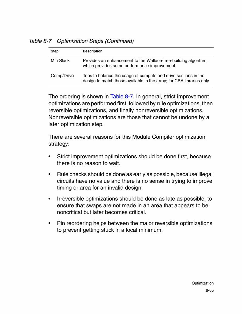
The ordering is shown in Table 8-7. In general, strict improvement optimizations are performed first, followed by rule optimizations, then reversible optimizations, and finally nonreversible optimizations. Nonreversible optimizations are those that cannot be undone by a later optimization step.
There are several reasons for this Module Compiler optimization strategy:
• Strict improvement optimizations should be done first, because there is no reason to wait.
• Rule checks should be done as early as possible, because illegal circuits have no value and there is no sense in trying to improve timing or area for an invalid design.
• Irreversible optimizations should be done as late as possible, to ensure that swaps are not made in an area that appears to be noncritical but later becomes critical.
• Pin reordering helps between the major reversible optimizations to prevent getting stuck in a local minimum.
Min Slack Provides an enhancement to the Wallace-tree-building algorithm, which provides some performance improvement
Comp/Drive Tries to balance the usage of compute and drive sections in the design to match those available in the array; for CBA libraries only
Table 8-7 Optimization Steps (Continued)
Step Description
8-65
Optimization

Design Strategy
You can control the logic optimization process by
• Choosing which steps are performed
• Choosing the number of local iterations
• Choosing the number of global iterations
• Choosing when you use delay equalization
• Choosing which instances you optimize
Each optimization step described can be enabled or disabled from the GUI or by using the dp_logopt environment variable.
The logic optimization performed during synthesis and final optimization should not be disabled for normal operation. Many synthesis routines have been written with the expectation that logic minimization will improve many special cases. Disabling logic optimization can produce inferior results, with little improvement in execution time.
You can control the maximum number of times (local iterations) each optimization step is performed. Each optimization step is repeated locally the specified number of times or until no further progress can be made.
Generally, a value of 3 to 4 is a good choice. Smaller values can be useful for speeding up the execution time for large circuits. You can choose larger values to prevent Module Compiler from terminating while still making optimization progress.
8-66
Chapter 8: Analysis and Optimization

You can also specify the number of global iterations, through the GUI or through the Module Compiler environment variables. This number of iterations is always the same as the specified value, even if no apparent progress has been made. Generally, specifying two or three global iterations produces good results, but for certain structures, more iterations might be beneficial.
The Module Compiler environment variable dp_equalpass value specifies the number of global iterations to perform with delay equalization (to equalize over timing groups). For example, when the number of global iterations is set to 5 and dp_equalpass is set to 3, the first two global iterations do not use delay equalization; only the last three iterations use delay equalization.
If delay equalization is used, you must choose whether it should be global or local. To select global delay equalization, use the dp_equalglob variable set to +. For local equalization, use -.
The use of equalization can have dramatic effects on complex circuits. If all global iterations use equalization, you can make swaps early that reduce area in an apparently noncritical timing portion. Further optimization might turn the noncritical area into the critical area, due to improvements in the previously critical paths.
If the swaps are irreversible, the circuit performance suffers. If you do not use equalization, critical paths might not be improved, because less-critical paths that have also not met the delay goal will not tolerate any slowdown.
A good compromise is to perform one or two global iterations without equalization, followed by one or two with equalization. Normally, you should choose local equalization when you want to see how close each group has come to achieving the delay goal.
8-67
Optimization

Global equalization can cause some groups within the same timing group to slow to the delay of the slowest group in the timing group. Also, because global equalization causes some groups within the same timing group to slow down, it saves area.
Optimization Example
Example 8-17 on page 8-70 shows the optimization log for a complex design with many groups. This design includes pipelining, loops, RAMs, shift registers with pipeline loaning, and latency equalization.
This design was optimized for a delay of 11.75 ns with two global passes, one of which employed local equalization. The number of local iterations was set to four, and all optimization steps were enabled.
Note the following in Example 8-17:
• The critical path moves between groups during the optimization. Although this design employs groups with different delay goals, all the critical groups have the same delay goal. When the critical path changes between groups with different delay goals, be sure to look at the slack rather than the delay numbers to monitor progress. In this case, the optimizer was successful in driving the slack to 0.
• Timing optimization increases the area and therefore the power of the circuit while decreasing the critical path delay. Note that a negative number in the “net changes” section indicates growth in either instances or sections. In the second pass, when the delay goal has been met, the timing optimization step is skipped.
8-68
Chapter 8: Analysis and Optimization

• Overloaded nets were repaired without an increase in critical path length. When the critical path length increases during this step, you should try to buffer or isolate the affected nets.
• Example 8-17 is from a CBA library with an intrinsic compute-to-drive ratio of 3.0.
• The area measure includes the compute-to-drive ratio, and the area optimization drives this ratio to 3.0. The total number of sections was increased during some logic minimization steps to improve the compute-to-drive ratio.
• The optimizer makes numerous swaps. The design ends up with 3,771 instances after making 11,953 swaps, with each instance being swapped about three times. During these swaps, 983 instances and 4,556 sections were removed. The timing improved by 1.72 ns.
Note:
The Power field is not available, starting with release 2001.08. Use Power Compiler to optimize for power.
8-69
Optimization

Example 8-17 Optimization Log for a Module Compiler Language DesignBeginning Timing Optimization ... TIMING (ns) AREA OPTIMIZATION NET CHANGES crit delay slack inst area Step swaps inst area group------------------------------------------------------------------------------ 2.455 17.55 68381 1322836 Gate Eater 0 0 0 qbpf 2.455 17.55 68381 1322836 Rules 32 -37 -888 qbpf 2.393 17.61 68418 1323724 Rules 0 0 0 mult
Pass 1, Full Timing Model, Not Equalizing Delays ... TIMING (ns) AREA OPTIMIZATION NET CHANGES crit delay slack inst area Step swaps inst area group------------------------------------------------------------------------------ 2.393 17.61 68418 1323724 LogicMin1 1037 25 7633 mult 2.743 17.26 68393 1316091 LogicMin1 0 0 0 mult 2.743 17.26 68393 1316091 LogicMin5 48 -24 -596 mult 2.743 17.26 68417 1316687 LogicMin5 0 0 0 mult 2.743 17.26 68417 1316687 Gate Eater 24 24 120 mult 2.743 17.26 68393 1316567 Gate Eater 0 0 0 mult 2.743 17.26 68393 1316567 Reorder 963 0 0 mult 2.743 17.26 68393 1316567 Area 44631 0 678034 mult 3.627 16.37 68393 638533 Area 27880 0 53196 LPF 4.543 15.46 68393 585337 Area 4733 0 18691 LPF 4.480 15.52 68393 566646 Area 196 0 512 LPF 4.482 15.52 68393 566134 LogicMin2 3279 3279 16383 LPF 4.029 15.97 65114 549751 LogicMin2 0 0 0 mult 4.029 15.97 65114 549751 LogicMin3 474 474 1898 mult 4.029 15.97 64640 547853 LogicMin3 30 30 69 LPF 4.031 15.97 64610 547784 LogicMin3 0 0 0 mult 4.031 15.97 64610 547784 LogicMin4 172 172 -83 mult 4.034 15.97 64438 547867 LogicMin4 2 2 0 LPF 4.034 15.97 64436 547867 LogicMin4 1 1 -2 LPF 4.034 15.97 64435 547869 LogicMin4 1 1 -1 LPF
Pass 2, Full Timing Model, Equalizing Delays Globally ... TIMING (ns) AREA OPTIMIZATION NET CHANGES crit delay slack inst area Step swaps inst area group------------------------------------------------------------------------------ 4.031 15.97 64434 547870 LogicMin1 0 0 0 LPF 4.031 15.97 64434 547870 LogicMin5 0 0 0 LPF 4.031 15.97 64434 547870 Gate Eater 0 0 0 LPF 4.031 15.97 64434 547870 Reorder 3197 0 0 LPF 4.031 15.97 64434 547870 Area 214 0 1255 LPF 4.036 15.96 64434 546615 Area 10 0 38 LPF 4.036 15.96 64434 546577 Area 5 0 19 LPF 4.036 15.96 64434 546558 Area 0 0 0 LPF 4.036 15.96 64434 546558 LogicMin2 46 46 310 LPF 4.036 15.96 64388 546248 LogicMin2 0 0 0 LPF
8-70
Chapter 8: Analysis and Optimization

4.036 15.96 64388 546248 LogicMin3 8 8 27 LPF 4.036 15.96 64380 546221 LogicMin3 0 0 0 LPF 4.036 15.96 64380 546221 LogicMin4 1 1 0 LPF 4.036 15.96 64379 546221 LogicMin4 0 0 0 LPF 4.036 15.96 64379 546221 Gate Eater 0 0 0 LPF
8-71
Optimization

8-72
Chapter 8: Analysis and Optimization

9Advanced Topics 9
This chapter provides a behind-the-scenes look at synthesis in Module Compiler and describes some advanced design techniques.
This chapter includes the following sections:
• Arithmetic Computation
• Multiplication
• Rounding
• Wallace Tree Reduction
• Carry-Propagate Adder Optimization
• Carry-Propagate Adder Architectures
9-1

• Ripple Adder Optimization
• Carry-Save Operands
• AND, OR, and XOR
9-2
Chapter 9: Advanced Topics

Arithmetic Computation
Of all the built-in functions, the integer arithmetic functions are the most complex. These functions often have the greatest influence on the performance and area of a circuit. Addition, subtraction, and multiplication use addition as the base function.
The processes involved with addition are shown in Figure 9-1. The figures on the right show an example of the bit patterns that might exist at each stage of the process for the case of a 10 x 5 multiplication being summed with a wider signal. The carry-save bit format is shown for a case in which the carrysave attribute has been set to optimize.
9-3
Arithmetic Computation

Figure 9-1 Addition Architecture
After the addend generation, a potentially large queue of bits is formed. The two carry-save inputs contribute the two wide sets of bits, and the multiplication contributes the parallelogram-shaped set of bits.
After the Wallace tree reduction, which includes a partial carry-propagate reduction, there are two sections in the bit queue. The one to the right has only 1 bit per bit position and needs no further processing.
Binary inputs
Carry-save inputs
Binary output
Function multtype
maxtreedepth
fatype
Wallace treereduction
Final addergeneration
Addendgeneration
Stages Bit Patterns
9-4
Chapter 9: Advanced Topics
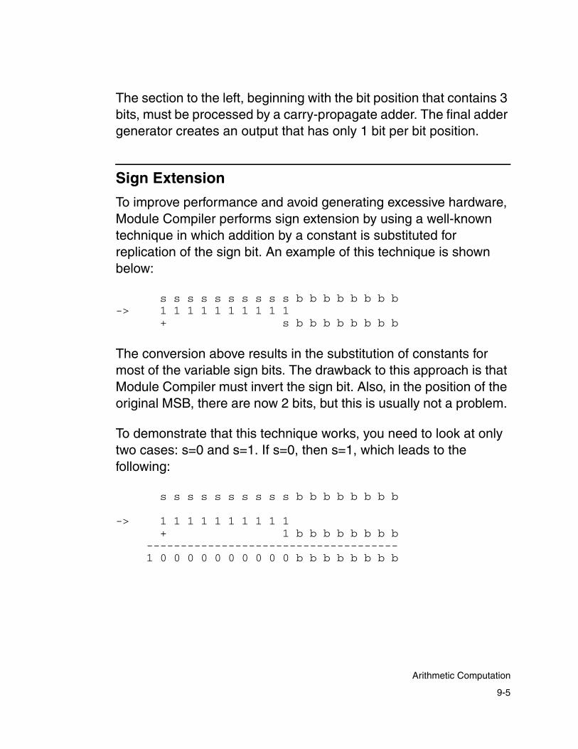
The section to the left, beginning with the bit position that contains 3 bits, must be processed by a carry-propagate adder. The final adder generator creates an output that has only 1 bit per bit position.
Sign Extension
To improve performance and avoid generating excessive hardware, Module Compiler performs sign extension by using a well-known technique in which addition by a constant is substituted for replication of the sign bit. An example of this technique is shown below:
s s s s s s s s s s b b b b b b b b-> 1 1 1 1 1 1 1 1 1 1
+ s b b b b b b b b
The conversion above results in the substitution of constants for most of the variable sign bits. The drawback to this approach is that Module Compiler must invert the sign bit. Also, in the position of the original MSB, there are now 2 bits, but this is usually not a problem.
To demonstrate that this technique works, you need to look at only two cases: s=0 and s=1. If s=0, then s=1, which leads to the following:
s s s s s s s s s s b b b b b b b b
-> 1 1 1 1 1 1 1 1 1 1+ 1 b b b b b b b b
-------------------------------------1 0 0 0 0 0 0 0 0 0 0 b b b b b b b b
9-5
Arithmetic Computation

Note that the answer is the correct sign-extended result, ignoring the carry-out, which is discarded. However, when dealing with carry-save formats, you do need to worry about the carry-out. When s=1, then s=0, and you can see that this scheme also works:
s s s s s s s s s s b b b b b b b b
-> 1 1 1 1 1 1 1 1 1 1+ 0 b b b b b b b b-----------------------------------1 1 1 1 1 1 1 1 1 1 b b b b b b b b
The real advantage of this technique comes when many addends must be sign-extended and summed. The constants can be added in advance, resulting in no additional sign-extension hardware.
This scheme has potential problems for a few simple cases, as shown below. In this case, two signed operands that have different widths are summed.
s s s s s b b b b b b b b b b b b b + S S S S S S S S B B B B B B B B B B-----------------------------------
-> 1 1 1 1 1s b b b b b b b b b b b b b
1 1 1 1 1 1 1 1s B B B B B B B B B B
-----------------------------------
-> 1 1 1 1 0 1 1 1s b b b b b b b b b b b b b
s B B B B B B B B B B-----------------------------------
11 2 1 0
9-6
Chapter 9: Advanced Topics
The problem is that the original “no tricks” solution requires a simple 2-input adder. After applying the sign-extension trick, you have a problem in bit position 10, where three items must be added, including an inverted signal. Not only is this solution slower but it is also likely to be larger.
To handle this problem, all addition-based functions can use simple sign extension. Module Compiler does not perform extension when the sign bit of an addend is aligned with the sign bit of the result.
Another potential inefficiency exists when the output bit range is wider than needed. The internal sign extension works properly, but the final adder depth and width increase to propagate the carry bits to the sign-extension bits, resulting in a larger, slower circuit.
The dirext attribute forces direct sign extension in sum-based operations. If the attribute is set to off, Module Compiler performs sign extension by adding a constant value rather than by replicating the sign bit. Direct sign extension should be used for adding or subtracting two operands for different widths.
In general, it is much more efficient to compute only as many bits as you need in order to perform the sign extension after the addition-based operation. This is a manual technique.
Addition and Subtraction
Addition and subtraction result in simple addend generation. For addition, Module Compiler forms the addend generated for summation in the Wallace tree by sign-extending the input operand, as discussed previously. Module Compiler generates addends for subtracted operands by inverting, sign-extending, and adding a constant 1 to the input operand.
9-7
Arithmetic Computation
Multiplication
Multiplication affects only the first part of the addition operation, the generation of addends. Each multiplication architecture generates the addends in a slightly different way.
Currently, four multiplication architectures are implemented with addition: a simple non-Booth-encoded multiplier, a Booth-encoded multiplier, a sign multiplier, and a multiplier architecture optimized for squaring.
All multipliers adjust automatically to any combination of formats—signed or unsigned—at the two inputs. You can also shift the product to the left with respect to the LSB of the result.
Note: For the purpose of describing the multiplier types in the following sections, the left input is referred to as input X and the right input is referred to as input Y.
Non-Booth-Encoded Multiplier
The non-Booth-encoded multiplier generates addends using simple logic: inverters for buffering, NOR gates for the basic partial product generators, and OR gates for the sign bits of the partial product generators.
This type of multiplier generates N partial products of M bits each, where N is the width of the Y input and M is the width of the X input. The non-Booth-encoded multiplier is relatively efficient when N and M are small numbers.
9-8
Chapter 9: Advanced Topics
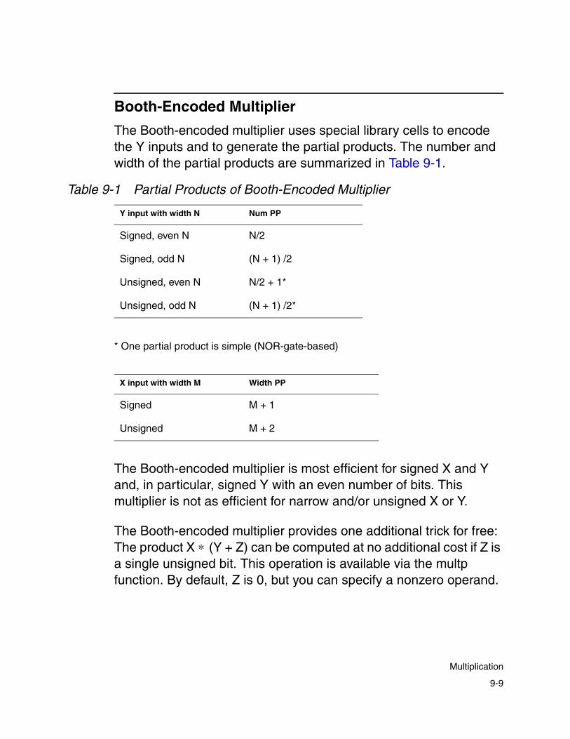
Booth-Encoded Multiplier
The Booth-encoded multiplier uses special library cells to encode the Y inputs and to generate the partial products. The number and width of the partial products are summarized in Table 9-1.
The Booth-encoded multiplier is most efficient for signed X and Y and, in particular, signed Y with an even number of bits. This multiplier is not as efficient for narrow and/or unsigned X or Y.
The Booth-encoded multiplier provides one additional trick for free: The product X ∗ (Y + Z) can be computed at no additional cost if Z is a single unsigned bit. This operation is available via the multp function. By default, Z is 0, but you can specify a nonzero operand.
Table 9-1 Partial Products of Booth-Encoded Multiplier
Y input with width N Num PP
Signed, even N N/2
Signed, odd N (N + 1) /2
Unsigned, even N N/2 + 1*
Unsigned, odd N (N + 1) /2*
* One partial product is simple (NOR-gate-based)
X input with width M Width PP
Signed M + 1
Unsigned M + 2
9-9
Multiplication
The offset can be used to your advantage in a couple of ways:
• −XY can be computed as X ∗ (~Y + 1).
• You can use the offset to generate a “true 1” coefficient to the multiplier, by setting Z to 1 and Y to a full-scale positive number.
Signed Multiplier
The signed multiplier is used to multiply an operand (X) of any format and width by plus or minus 1 (the sign of Y). Only the sign bit of the Y input is used. If Y is negative, the result is −X; otherwise, it is +X. If Y is unsigned, Module Compiler issues a warning. This multiplier is specified with the sgnmult function.
Constant Multiplier
Multiplication of a constant by a variable operand deserves some special mention, even though no special syntax is required. The constant operand is used to generate a set of addends that are scaled versions (positive, negative, and shifted) of the variable operand.
The constant is optimized to minimize the total number of addends generated in a manner similar to, yet more efficient than, Booth encoding. This type of operation is affected by fatype but not by multtype.
9-10
Chapter 9: Advanced Topics
Squaring Multiplier
Expressions of the form X ∗ X result in a special multiplier type, called the squaring multiplier, that is smaller (usually by 40 to 50 percent) and faster than a normal multiplier. The multtype has no effect on this multiplier, but fatype works the same as for other multiplier types.
Rounding
Two types of rounding are available in Module Compiler: simple and internal rounding.
Simple Rounding
Simple rounding is used to round a calculated arithmetic result at a specified bit position by adding a constant value of 1 to the bit below the rounded bit in the final result. Simple rounding is usually followed by manual truncation of the result at the rounded-bit position. This type of rounding is biased, because only the bit below the final LSB is considered in the rounding. The remaining lower bits are ignored in this operation.
To specify the rounding bit, use the round attribute. The rounding applies only to arithmetic expressions. By default, the round attribute is set to 0, which means that no simple rounding is performed. As illustrated in Figure 9-2, if round is set to 4 and the arithmetic result is assigned to an 8-bit signal called sum, 1 is added at sum[3] in the fourth bit and the new LSB is sum[4]. This extra rounding addend is added internally in the arithmetic expression, so the result reflects the effect of the rounding. The resulting signal
9-11
Rounding

contains the new rounded portion plus the extra lower bits, so signal mapping or shifting is used to truncate the signal to the rounded result.
Figure 9-2 Simple Rounding
1 0 0 1 1 1 00
7 6 5 4 3 2 1 0
1 0 1 0 0 1 00
7 6 5 4 3 2 1 0
1 1 00
3 2 1 0
sum
sum
final_sum
1 0 00 extra round addend internal addition of round addend
manual bittruncation
directive (round=4);
round position
9-12
Chapter 9: Advanced Topics

Internal Rounding
Internal rounding is used to make a tradeoff between area and precision in arithmetic expressions. It works by truncating bits from the internal addends of an arithmetic expression. This reduces the circuit area, because fewer bits are being summed by the final adder.
Use the intround attribute to set the level of internal rounding. By default, the value of this attribute is 0, which means that no internal rounding is performed. Increasing the value of intround increases the number of bits that are discarded from the internal addends in the arithmetic expression. For example, if you set the intround attribute to 5, all of the bits contributing to the lower bits, up to bit 5, in the final result are discarded from the internal addends in the expression. This is illustrated in Figure 9-3, which shows an 8 x 8 multiplier with unsigned inputs and non-Booth encoding.
9-13
Rounding

Figure 9-3 Internal Rounding
Internal rounding can be used in digital signal processing applications in which the input signals to the expression contain inaccuracies due to previous rounding or truncation. However, if the inputs are exact and an exact output is required, internal rounding should not be used.
Module Compiler generates a behavioral simulation file that correctly models the internal rounding bit manipulation. Use this simulation file to verify that the altered functionality due to internal rounding is acceptable.
When internal rounding is activated, Module Compiler generates an additional section in the design report called “Internal Rounding Error Analysis.” This report allows you to calculate exactly how much
directive (intround=5) ;
Discarded bits frominternal addends
9-14
Chapter 9: Advanced Topics
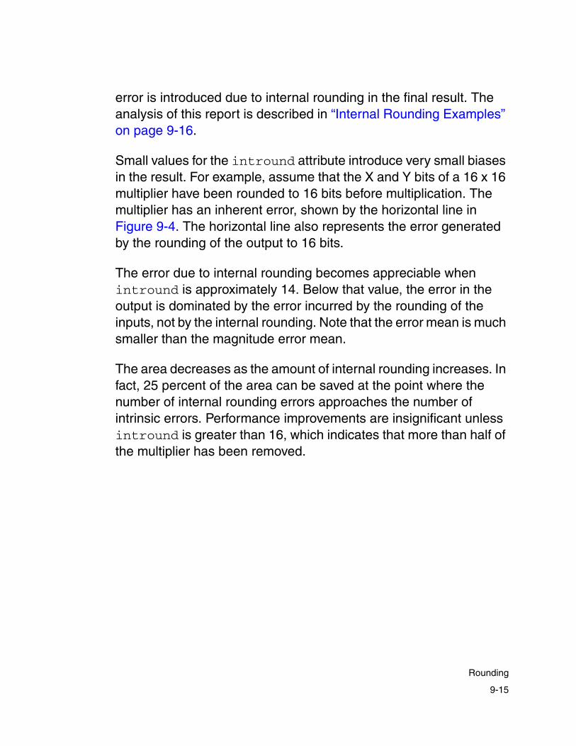
error is introduced due to internal rounding in the final result. The analysis of this report is described in “Internal Rounding Examples” on page 9-16.
Small values for the intround attribute introduce very small biases in the result. For example, assume that the X and Y bits of a 16 x 16 multiplier have been rounded to 16 bits before multiplication. The multiplier has an inherent error, shown by the horizontal line in Figure 9-4. The horizontal line also represents the error generated by the rounding of the output to 16 bits.
The error due to internal rounding becomes appreciable when intround is approximately 14. Below that value, the error in the output is dominated by the error incurred by the rounding of the inputs, not by the internal rounding. Note that the error mean is much smaller than the magnitude error mean.
The area decreases as the amount of internal rounding increases. In fact, 25 percent of the area can be saved at the point where the number of internal rounding errors approaches the number of intrinsic errors. Performance improvements are insignificant unless intround is greater than 16, which indicates that more than half of the multiplier has been removed.
9-15
Rounding

Figure 9-4 Effect of the intround Attribute on Multiplier Error
Internal Rounding Examples
This section provides an example of a design in Module Compiler, shows a report excerpt of internal rounding error, and covers two approaches to computing the maximum error introduced. Using one of these two approaches, you can better determine the area-versus- accuracy tradeoffs when using internal rounding.
The purpose of using internal rounding is to find additional area savings at the expense of allowed accuracy of results. To make this tradeoff, you need to interpret the Module Compiler internal rounding report to compute the maximum error introduced.
16x16 Multiplier Error
0.01
1
100
10000
1000000
100000000
10000000000
1 6 11 16 21 26 31
intround
Mean Err
Mean Mag Err
Peak Err
Intrinsic Err
inherent errorerror
9-16
Chapter 9: Advanced Topics

Example 9-1 Internal Rounding Error Analysis
module test (z,a,b);directive(round=8,intround=5,multtype="booth");input signed [8] a,b;wire signed [16] z1=a*b;output signed [8] z=z1>>8;endmodule
Example 9-1 shows a multiplier that uses the intround directive for internal rounding. Whenever the intround directive is used, Module Compiler generates an internal rounding analysis report, which provides information on the extent of numerical error introduced. Module Compiler reports the rounding error as shown in Example 9-2.
Using the information from the Internal Rounding Error Analysis report (Example 9-2) can be valuable in trading off numerical precision versus additional hardware costs. You can determine the total maximum error by using a relative error approach or an absolute error approach. The relative error approach is shown in Figure 9-5.
Example 9-2 Report Excerpt of Internal Rounding Error
Internal Rounding Error Analysis Relative Absolutename Rnd Max Min Av Max Min Av--------------------------------------------------------
z1 5 1.66 -0.84 0.41 53 -27 13
9-17
Rounding

Figure 9-5 Relative Error Approach
The maximum internal rounding error of –0.84 to +1.66 can be treated conservatively as +/-2 LSBs, with respect to bit 5, the internal rounding position. This is also equivalent to a +/– 1-bit error at bit 6. Simple rounding produces an error of +/–1/2, at bit 8. This is equivalent to a 1-bit error at bit 7. The total rounding error is +/– 3/4, with respect to bit 8, the new LSB.
The absolute error approach is shown in Figure 9-6. The report excerpt is repeated for convenience.
Internal Rounding Error Analysis Relative Absolutename Rnd Max Min Av Max Min Av--------------------------------------------------------
z1 5 1.66 -0.84 0.41 53 -27 13
Relative error = -0.84 to 1.66
bit 7
1
Error from “ round”
bit 8 bit 6 bit 5 bit 4 bit 3 bit 2 bit 1
1
bit 0
Relative error: -0.84 to + 1.66 Error from “intround”
1/2 = 0.5
“intround” position“round” position
1/64 1/256 1/1281/32 1/16 1/2 1/81/4
+/- 2LSB with respect to bit 51/4 = 0.25 with respect to bit 8
Total error0.5 + 0.25 = 0.75 LSBs
9-18
Chapter 9: Advanced Topics
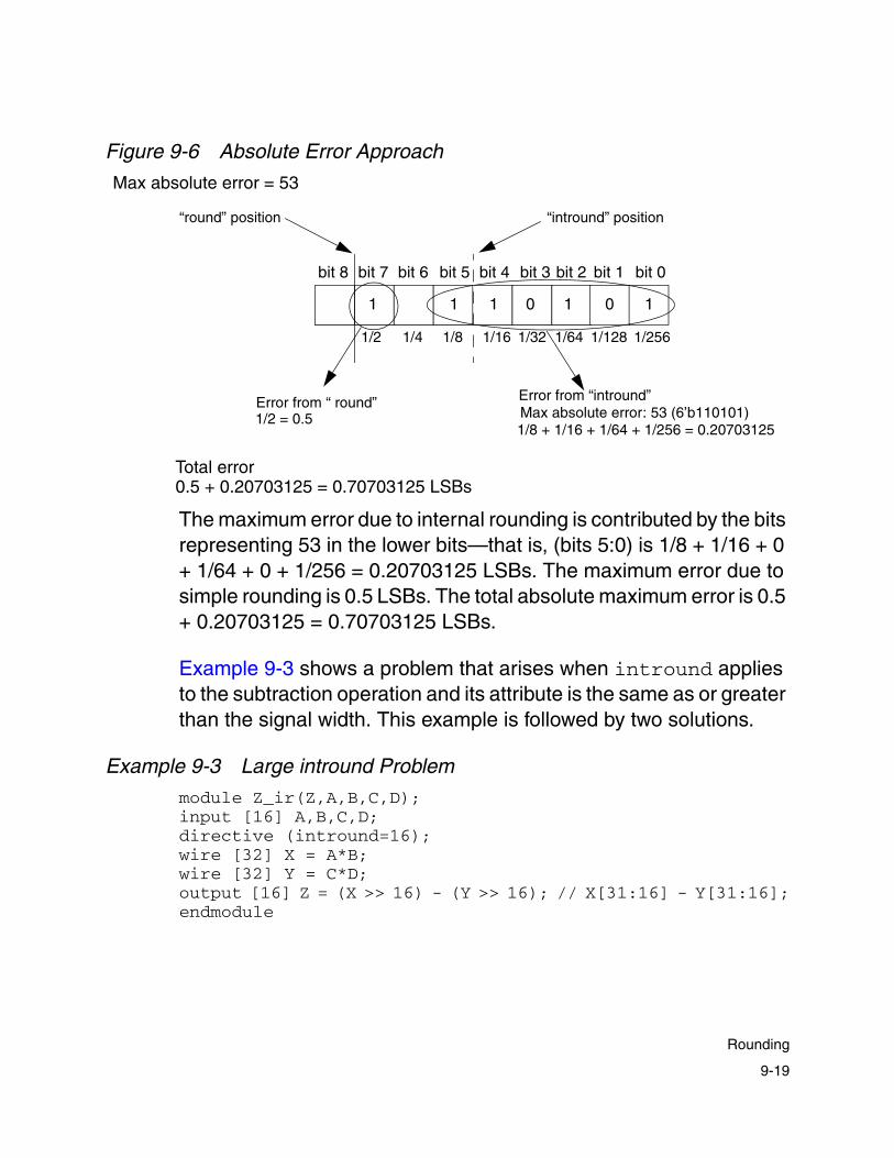
Figure 9-6 Absolute Error Approach
The maximum error due to internal rounding is contributed by the bits representing 53 in the lower bits—that is, (bits 5:0) is 1/8 + 1/16 + 0 + 1/64 + 0 + 1/256 = 0.20703125 LSBs. The maximum error due to simple rounding is 0.5 LSBs. The total absolute maximum error is 0.5 + 0.20703125 = 0.70703125 LSBs.
Example 9-3 shows a problem that arises when intround applies to the subtraction operation and its attribute is the same as or greater than the signal width. This example is followed by two solutions.
Example 9-3 Large intround Problem
module Z_ir(Z,A,B,C,D);input [16] A,B,C,D;directive (intround=16);wire [32] X = A*B;wire [32] Y = C*D;output [16] Z = (X >> 16) - (Y >> 16); // X[31:16] - Y[31:16];endmodule
bit 7
1 1
Error from “ round”
bit 8 bit 6 bit 5 bit 4 bit 3 bit 2 bit 1
0 0 111
bit 0
1/8 + 1/16 + 1/64 + 1/256 = 0.20703125Max absolute error: 53 (6’b110101)Error from “intround”
1/2 = 0.5
Max absolute error = 53
“intround” position“round” position
1/64 1/256 1/1281/32 1/16 1/2 1/81/4
Total error0.5 + 0.20703125 = 0.70703125 LSBs
9-19
Rounding

During synthesis at the following line
output [16] Z = (X >> 16) - (Y >> 16);
Module Compiler generates the following warning:
Warning: (SYN92) Internal rounding set beyond msb,result will be zero!
The SYN92 warning appears because output Z is 0. This is because all partial products evaluate to 0 whenever intround applies to the subtraction operation and its attribute is the same as or greater than the signal width.
In Example 9-3, the signal width is 16 bits and the intround attribute is also 16 bits, which results in a partial product of 0. You can avoid this problem by using a local directive or by setting the intround attribute to 0 after the expressions where the rounding is applied.
Example 9-4 Solution Using Local Directive for intround
module Z_ir(Z,A,B,C,D);input [16] A,B,C,D;directive local (intround=16);wire [32] X = A*B;directive local (intround=16);wire [32] Y = C*D;output [16] Z = (X >> 16) - (Y >> 16); // X[31:16] - Y[31:16];endmodule
In Example 9-4, the scope of a local directive applies only to the following statement. Therefore, the intround attribute does not apply to the subtraction operation and no synthesis error results.
9-20
Chapter 9: Advanced Topics
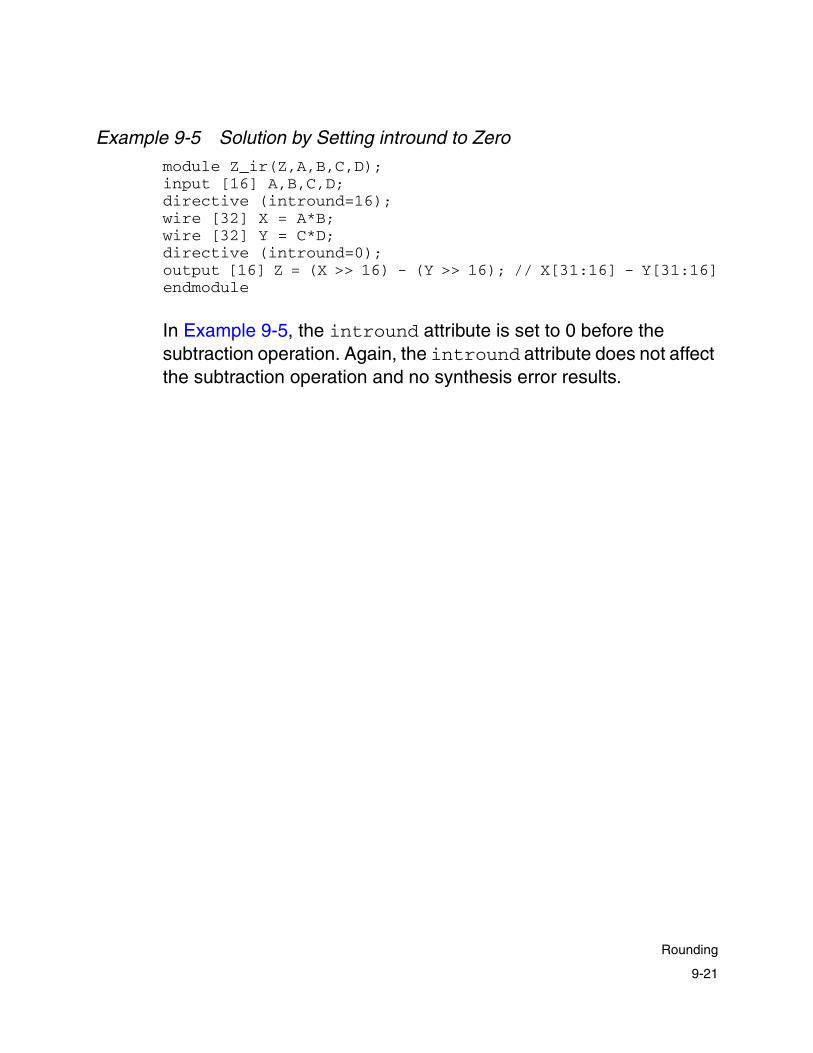
Example 9-5 Solution by Setting intround to Zero
module Z_ir(Z,A,B,C,D);input [16] A,B,C,D;directive (intround=16);wire [32] X = A*B;wire [32] Y = C*D;directive (intround=0);output [16] Z = (X >> 16) - (Y >> 16); // X[31:16] - Y[31:16]endmodule
In Example 9-5, the intround attribute is set to 0 before the subtraction operation. Again, the intround attribute does not affect the subtraction operation and no synthesis error results.
9-21
Rounding

Wallace Tree Reduction
After Module Compiler generates all the addends with the constructs described previously, it uses the Wallace tree algorithm to reduce the number of signals to a maximum of two or three per bit position. Module Compiler automatically determines when three signals are allowed in a given bit position without degradation of the timing of the final adder.
Module Compiler uses a final carry-propagate adder to generate a binary result. This reduction happens automatically and is very efficient. It does not result in any hardware when none is needed.
You use the maxtreedepth directive to limit the depth, or scope, of Wallace trees. In general, large Wallace trees improve performance. However, Wallace trees are global structures and utilization suffers if the design includes very large trees. The proper use of this directive allows you to effectively create a serial connection of Wallace trees without changing the network description.
The maxtreedepth directive works by allowing only the number of signals in each bit position of the Wallace tree queue to reach the value of the maxtreedepth attribute. When Module Compiler reaches this value, it performs a Wallace tree reduction.
For example, suppose you want to build a sum of products with sixty-four 8 x 8 products. Assuming the use of a non-Booth-encoded multiplier, the middle bit positions will contain 64 ∗ 8 = 512 bits, resulting in poor utilization.
Setting maxtreedepth to 32 causes performance degradation but significantly improves utilization. By default, Module Compiler sets this attribute to a very large number.
9-22
Chapter 9: Advanced Topics

Carry-Propagate Adder Optimization
Module Compiler automatically breaks carry-propagate adders into multiple adders if possible and allows the greatest number of signals in each bit position. This optimization makes it possible to have 3 bits in the lowest bit of the adder without a significant area or performance penalty.
In general, Module Compiler determines what bit positions can have a carry input. If no carry input from a preceding stage is possible, the adder is broken and 3 bits are allowed in the next bit position. For example, consider the sum of signals shown in Figure 9-7.
Figure 9-7 Carry-Propagate Adder Optimization
This complex example, involving the sum of six different operands, illustrates several concepts. Because of the breaks between the operand groups, the problem can be solved with three small adders. The three adders operate in parallel and are smaller and faster than a single large adder.
In addition, 3 bits are allowed at points A, B, and C without invocation of a Wallace tree reduction, even though point A is not the first bit of the stage. Note that the bits to the right of A are not input to any carry-propagate adder.
C B A
Adder 3 Adder 2 Adder 1
Break Break
9-23
Carry-Propagate Adder Optimization

Less-sophisticated approaches might solve this problem with a Wallace tree reduction, because of the bits at C and B (and perhaps even at A), and generate a single carry-propagate adder.
Carry-Propagate Adder Architectures
For most computations, you want a binary result and need to use a final carry-propagate adder. Module Compiler provides several carry-propagate microarchitectures. Each has advantages and disadvantages. These fatype attributes are summarized in Table 9-2.
Table 9-2 fatype Attributes
fatype Description Area Delay Use arrival times
Use desired delay
When used as the default
aofcla Area-optimized fast-carry-lookahead
Dynamic O(log2(n)) No No Never
cla Carry-lookahead
O(n) O(log2(n)) No No pipeline=on
clsa Carry-lookahead-select
Variable ripple->fastcla
Variable ripple-> fastcla
Yes Yes pipeline=offNot optimized for speed
csa Carry-select O(n) O Yes Yes Never
fastcla Fast-carry-lookahead
O(n log2(n ))
O(log2(n)) No No pipeline=offOptimized for speed
ripple Ripple O(n) O(n) No No Never
n
9-24
Chapter 9: Advanced Topics
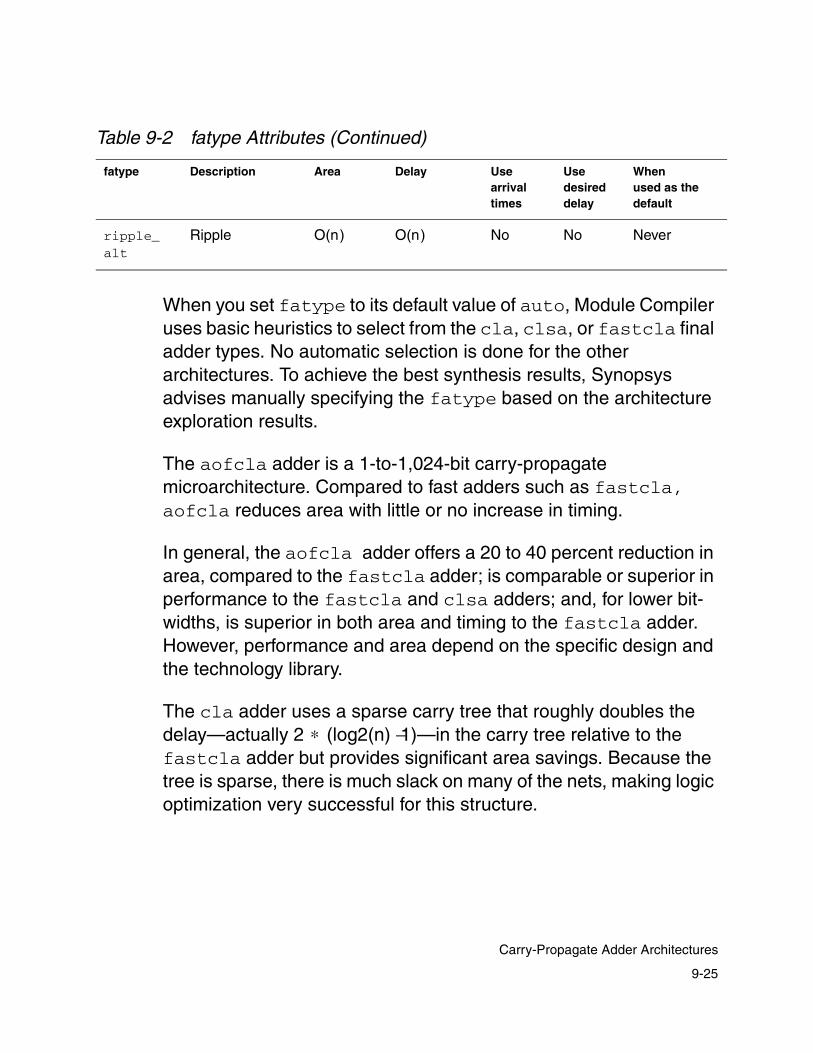
When you set fatype to its default value of auto, Module Compiler uses basic heuristics to select from the cla, clsa, or fastcla final adder types. No automatic selection is done for the other architectures. To achieve the best synthesis results, Synopsys advises manually specifying the fatype based on the architecture exploration results.
The aofcla adder is a 1-to-1,024-bit carry-propagate microarchitecture. Compared to fast adders such as fastcla, aofcla reduces area with little or no increase in timing.
In general, the aofcla adder offers a 20 to 40 percent reduction in area, compared to the fastcla adder; is comparable or superior in performance to the fastcla and clsa adders; and, for lower bit- widths, is superior in both area and timing to the fastcla adder. However, performance and area depend on the specific design and the technology library.
The cla adder uses a sparse carry tree that roughly doubles the delay—actually 2 ∗ (log2(n) −1)—in the carry tree relative to the fastcla adder but provides significant area savings. Because the tree is sparse, there is much slack on many of the nets, making logic optimization very successful for this structure.
ripple_alt
Ripple O(n) O(n) No No Never
Table 9-2 fatype Attributes (Continued)
fatype Description Area Delay Use arrival times
Use desired delay
When used as the default
9-25
Carry-Propagate Adder Architectures

The clsa adder is a good general choice, especially with large delay skews, but it does not pipeline well. It is by far the most flexible architecture and automatically creates a structure ranging from a ripple to a fastcla adder, depending on the desired delay.
The csa adder is not a particularly high-performance adder, at best achieving only O( )delay. In reality, the growing loading on the carry-select lines degrades performance below the expected level.
When pipelining is enabled, Module Compiler attempts to break the csa adder into stages that fall into different pipeline sections, instead of allowing pipelining inside a stage. This addition to the algorithm often provides an advantage when there are large delay skews, as in a multiplier.
The fastcla adder is usually the fastest architecture, but it is also the largest. It uses a dense carry tree to propagate the carries to each bit, in only log2(n) inverting AND-OR delays.
Besides the carry tree, an XOR delay occurs in the sum generation and one NAND delay occurs in the initial G and P generation. The fanouts on the drivers in the carry tree are constant, yet the actual routing complexity grows with the number of bits. This structure is very balanced and tends to improve only minimally during logic optimization.
The ripple adder is a small, slow adder structure. This architecture produces speed-efficient ripple adders. It maps to an alternating polarity chain of full adders with inverted carry-ins and carry-outs.
The ripple_alt adder—another small, slow structure—is most useful for generating area-efficient ripple adders. It uses only simple full-adder cells.
n
9-26
Chapter 9: Advanced Topics

The ripple and ripple_alt adders are technology independent and are most useful for noncritical portions of the design. Module Compiler can automatically choose the ripple adder that best satisfies design constraints. For more information, see “Ripple Adder Optimization.”
Ripple Adder Optimization
There are two types of optimized ripple adder architectures: inverting and noninverting. You can specify either of these architecture types as being optimized for speed or size.
Use the archtype and archopt Module Compiler Language attributes to control the ripple adder architecture. Use the archtype attribute to control the architecture of the ripple adder (inverting versus noninverting). Use the archopt attribute to set the optimization goal for the ripple adder. The default value for both attributes is auto; however, you can set the Module Compiler environment variables dp_archtype and dp_archopt to change the default values for the archtype and archopt attributes, respectively.
Use fat=ripple to specify that a ripple adder is used for the final adder.
• You can set archtype to the following values:
- auto maps to the best synthesized architecture before logic optimization, based on the archopt attribute setting.
- inverting maps to the existing fatype=ripple attribute setting, providing backward compatibility. This setting is used with archopt set to none.
9-27
Ripple Adder Optimization

- noninverting maps to the existing fatype=ripple_alt attribute setting, providing backward compatibility. This setting is used with archopt set to none.
• You can set archopt to the following values:
- speed maps to a speed-optimized ripple adder cell selection.
- size maps to an area-optimized ripple adder cell selection.
- auto maps to the specified design goal. By default, the design goal is set to speed, unless you set the dp_opt Module Compiler environment variable to size.
- none provides backward compatibility. This setting is used with archtype set to inverting or noninverting.
The scope of these attributes is similar to other Module Compiler Language attributes, in that the attribute is in effect until it is reset in a subsequent directive.
9-28
Chapter 9: Advanced Topics

The following table shows how to use the new archtype and archopt attributes to optimize ripple adders.
Carry-Save Operands
The carry-propagate adders cost a great deal in terms of delay and area. In some cases, it is essential to avoid them. For such cases, it is possible to bypass the final adder and leave the output in carry-save format.
Note: You cannot model carry-save operands behaviorally until they have been added to another operand, and then only if no significant bits have been lost through bit ranging or other nonlinear operators. They are modeled just like normal binary signals.
Table 9-3 Ripple Adder Attribute Settings
fatype archtype archopt Resulting architecture
ripple inverting none Old speed-optimized architecture, previously (fatype=ripple)
ripple noninverting none Old area-optimized architecture, previously (fatype=ripple_alt)
ripple auto speed New speed-optimized architecture
ripple auto size New area-optimized architecture
ripple auto auto Select new architecture based on the dp_opt (optimization) setting
9-29
Carry-Save Operands

You can select three varieties of carry-save signals by changing the carrysave attribute, as summarized in Table 9-4:
When the carrysave attribute is set to on, the resulting signal does not have constants merged with variables, because it is expected to be summed with another carry-save signal with unmerged constants. Merging the constants early hurts performance and area. It allows up to 3 bits (actually three signals and one constant) in each bit position.
If only 2 bits were allowed, half-adders, which are very inefficient, would have to be used. They convert two input signals into two output signals, resulting in virtually no reduction. Half-adders are for use only immediately before the final addition.
The optimize carry-save signal has a lower total number of bits that must be summed with a non-carry-save signal. The assumption here is that the other inputs to the sum are more critical and should not be slowed further. Module Compiler merges constants and performs ripple addition on the LSBs to remove as many bits as possible without increasing the delay.
Table 9-4 carrysave Modes
carrysave Constants Maxbits Ripple add Module Compiler Language use
off Merged 1 No Evaluate binary result (default)
on Not merged 3 No When summed with a carry-save signal
optimize Merged 3 Yes When summed with a critical noncarry-save signal
convert Merged 2 No Access carry-save signals individually, using the csconvert function
9-30
Chapter 9: Advanced Topics

The convert carry-save signal is the traditional carry-save signal and is required when you convert a carry-save operand to two signed operands. It has no more than 2 bits in any bit position.
You can use a carry-save signal in only a few circumstances:
• It can be added, subtracted, or compared (>, >=, <, <=) with any operand and optionally shifted by a constant.
• It can be input to sreg, preg, or any eqreg.
Due to limitations of the current implementation, you should declare the carry-save signals with a bit-width. However, during synthesis, the true bit range is determined automatically and the user-provided range is ignored.
You should write all code with actual bit ranges, even for the carry-save signals. By doing this, you can toggle the carrysave attribute to attempt carry-save as well as binary implementations without any other code changes.
Note that the assignment operator alone always converts a carry-save signal to binary, regardless of the setting of the carrysave attribute. To have the assignment produce a carry-save signal, use the + operator, as shown in Example 9-6.
Example 9-6 Producing a Carry-Save Signal
directive (carrysave = "on");Z2 = A+B; //Z2 is a carrysaveZ3 = +Z2; //Z3 is a carrysaveZ4 = Z3; //Z4 is not a carrysave
In Example 9-7, a simple 32 x 32 multiplication is broken into four pieces that are kept in carry-save format. The four carry-save signals are summed to yield the final 64-bit product.
9-31
Carry-Save Operands

Example 9-7 Example of carrysave Usage
module mult32 (Z,X,Y);input [32] X;input [32] Y;output [64] Z;// no final adders for Z0,Z1,Z2,Z3
directive(carrysave="on"); wire [1] Z0,Z1,Z2,Z3;Z0=Y[8]*X;Z1=Y[15:8]*X;Z2=Y[23:16]*X;Z3=Y[31:24]*X;
directive(carrysave="off");Z=Z0+(Z1<<8)+(Z2<<16)+(Z3<<24); //Z must have final adder
endmodule
Individually Accessing Carry-Save Signals
The csconvert function allows you to access carry-save signals individually. It is important that you pay attention to the rules that govern the usage of csconvert, because if they are not followed, an RTL-versus-gate mismatch can occur.
Using csconvert is recommended only for experienced datapath designers, and it is recommended that you have experience with datapath design in Module Compiler prior to using this function.
When you are using csconvert, it is also recommended that you use the gate-level netlist for full functional verification.
9-32
Chapter 9: Advanced Topics
Using the csconvert function
You need to use csconvert only to gate or MUX signals that are in carry-save format. Many designs do not need this feature. Example 9-8 shows an example of the usage of csconvert.
Example 9-8 csconvert Usage
module csconverter (x, y, z);input unsigned [3] x, y;output [6] z;directive (carrysave = "convert", multtype = "nonbooth");wire [1] prod = x*y; // width and format are irrelevantwire unsigned [6] p0, p1; // width and format are relevantcsconvert (p0, p1, prod);// Turn off carrycave before final additiondirective (carrysave = "off");z = p0 + p1; //binary resultendmodule
There are a few things to note in Example 9-8:
1. Set the carrysave attribute.
carrysave = convert
Other values of the carrysave attribute—on and optimize—do not work and lead to an error message if set.
2. Declare the width and format of the carry-save terms.
wire unsigned [6] po, p1;
3. Use the csconvert function.
csconvert(p0, p1, prod)
The sum and carry values are now represented by wires p0 and p1, respectively.
9-33
Carry-Save Operands

4. Turn the carrysave attribute to off before the final addition.
directive (carrysave = "off");z = p0 + p1; //binary result
Example 9-9 Example of a Carry-Save Accumulator
module acc(Z,X,RESET);input signed [8] X;output signed [8] Z;input [1] RESET;wire signed [8] ACC0,ACC1,X1,XPR,ZA,RZA0,RZA1;wire signed [10] ZA0,ZA1; //determined from acc.reportACC0=sreg(RZA0);//need two sreg calls for carrysaveACC1=sreg(RZA1);
directive(carrysave="convert");//must use the convert option hereZA=X+ACC0+ACC1;csconvert(ZA0, ZA1, ZA); //generate two signed signals,ZA0,ZA1
directive(MUXtype="andor"); //now we can MUX the carrysave signalRZA0=RESET ? ZA0 : 0; //to allow the loop to be resetRZA1=RESET ? ZA1 : 0;
directive(carrysave="off",fatype="clsa");Z = ACC0 + ACC1;
endmodule
Example 9-9 uses a carry-save accumulator. In this case, the csconvert function is required in order to allow the feedback of the carry-save signal.
9-34
Chapter 9: Advanced Topics

Guidelines for csconvert Usage
The following guidelines must be strictly followed for correct usage of csconvert.
1. Correctly declare the width and format of the sum and carry terms.
You can determine the correct width of the sum and carry bits by looking at the “COMPUTED OPERANDS” subsection of the “Operand Summary” section of the Module Compiler design report (see Example 9-10).
The internal signals p0_mc_Z1_ and p0_mc_Z2_ contain the values of sum and carry terms. The bit ranges associated with these signals are the widths needed for csconvert to function correctly.
In Example 9-10, signal p0_mc_Z1_ has a bit range of [6:0] and signal p0_mc_Z2_ has a bit range of [5:0]. Because it is not apparent from the design report which internal signal is the sum term and which internal signal is the carry term, you should be conservative and use the higher bit range value, [6:0].
The correct width of the sum and carry terms is often greater than you expect. A greater width is necessary for proper sign extension if the sum and carry bits are signed. Therefore, correctly declaring the width of the sum and carry terms involves a two-pass process to first see what the width is and then to set the correct width in your Module Compiler code.
Pass 1: Define some arbitrary values for the width of the sum and carry terms. After running Module Compiler synthesis and optimization, check the design report (see Example 9-10) for the correct values of the sum and carry terms described above.
9-35
Carry-Save Operands
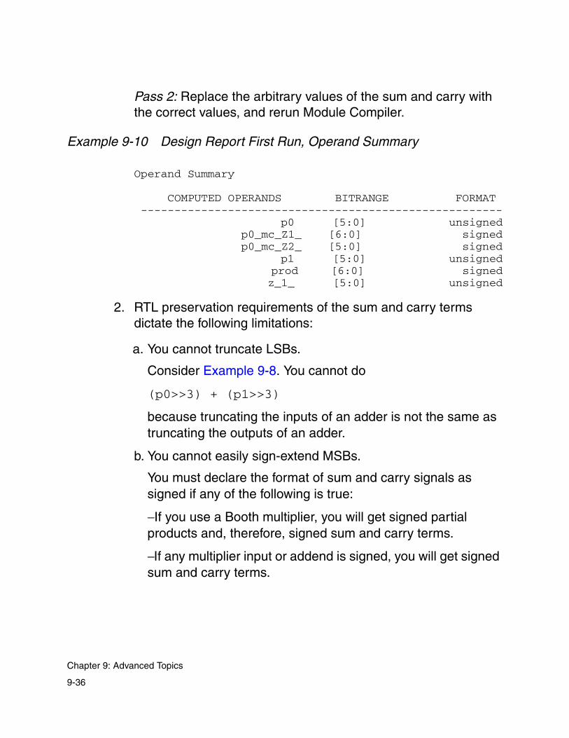
Pass 2: Replace the arbitrary values of the sum and carry with the correct values, and rerun Module Compiler.
Example 9-10 Design Report First Run, Operand Summary
Operand Summary
COMPUTED OPERANDS BITRANGE FORMAT ------------------------------------------------------ p0 [5:0] unsigned p0_mc_Z1_ [6:0] signed p0_mc_Z2_ [5:0] signed p1 [5:0] unsigned prod [6:0] signed z_1_ [5:0] unsigned
2. RTL preservation requirements of the sum and carry terms dictate the following limitations:
a. You cannot truncate LSBs.
Consider Example 9-8. You cannot do
(p0>>3) + (p1>>3)
because truncating the inputs of an adder is not the same as truncating the outputs of an adder.
b. You cannot easily sign-extend MSBs.
You must declare the format of sum and carry signals as signed if any of the following is true:
− If you use a Booth multiplier, you will get signed partial products and, therefore, signed sum and carry terms.
− If any multiplier input or addend is signed, you will get signed sum and carry terms.
9-36
Chapter 9: Advanced Topics

− If all the partial products and addends of the multiplier are unsigned, sum and carry terms can be unsigned. This applies, for example, to A * B if A and B are unsigned and the multiplier type is non-Booth.
c. You cannot look at the bits. In other words, you cannot take a bit range of sum and carry or assign individual bits to signals. You must consider them as a bus.
Sum and carry bits can be simultaneously reset (gated).
d. You cannot use sum and carry as module output. You must convert them to regular binary before using them as module output.
As long as the above rules are not violated, the RTL simulation model will be bit- and cycle-accurate when you use csconvert. There might be some carry-save designs that violate these rules.
Be sure to do all functional verification with the gate-level netlist.
AND, OR, and XOR
Each of these functions computes a bitwise logical function over the inputs. As with the addition-based functions, any number of inputs can be accommodated and degenerate cases can be handled efficiently.
Missing bits are treated as 0. For OR and XOR, there should be no confusion, because the 0s do not change the result. However, for AND, a 0 in any bit position causes the result for that bit position to be 0.
9-37
AND, OR, and XOR

Module Compiler directly supports the inversion of any input, including the missing bits that are inverted to 1s. You can implement NAND and NOR by inverting all the inputs and using the complementary function.
Shifting, selecting, and bit-ranging the output operand format occurs in the same manner as addition-based functions. You accomplish sign extension of inputs in the direct manner.
There are only two stages in the generation of the result: signal gathering and Wallace tree reduction.
Because there is no interaction between bits, the Wallace tree algorithm is used to reduce the inputs down to the final binary result. It has been modified slightly to allow true as well as inverted bits in the Wallace tree queue to increase the use of inverting logic, which is generally faster and smaller than noninverting logic.
Each function can be optimized for speed or area. There is no direct control over speed or area optimization, except through the current optimization criterion: The circuit is optimized for speed unless the delay goal set is very large, in which case these functions are optimized for area.
The AND and OR operations are particularly sensitive to the optimization style, because of the wide range of cells available (for example, two to eight inputs).
9-38
Chapter 9: Advanced Topics

10Module Compiler Pipelining 10
This chapter describes pipelining capabilities in Module Compiler and includes the following sections:
• Pipeline Overview
• Design Retiming in Design Compiler
• Automatic Input and Output Registering
• Pipelining Flows and Concepts
• Handling Latency
10-1

Pipeline Overview
Module Compiler provides the following pipeline capabilities:
• User-specified pipeline latency
• Automatic input and output registering
• Automatic and manual pipelining
• User-specified input and output latency
• Support for ensreg with pipestall
The Module Compiler pipelining design flow is shown in Figure 10-1.
Figure 10-1 Pipelining Design Flow
Latency constraints
Library file
Gate-level netlist
RTL simulation model
ModuleCompilerLanguage
Module
Compiler
Retimedgate-level netlist
Design Compiler Retiming
10-2
Chapter 10: Module Compiler Pipelining

As shown in Figure 10-1, the inputs to Module Compiler include specifying output signal latency, which is discussed later in this guide. For output, Module Compiler provides a retimed gate-level netlist.
You can specify output signal latency constraints and enable other pipelining capabilities using the Module Compiler GUI or the Module Compiler environment variables.
Design Retiming in Design Compiler
The benefits of design retiming are
• Balanced paths, which result in faster circuits without narrow or wide sections
• Reduced area, due to the reduction in flip-flops wherever possible in the design, because registers are moved from wider sections of logic to narrower sections
Note: The retiming capability within Module Compiler is no longer supported. To run Design Retiming, you must use register retiming in Design Compiler.
Design retiming does not change the latency of a design. Figure 10-2 gives an overview of retiming.
10-3
Design Retiming in Design Compiler

Figure 10-2 Overview of Retiming
If the delay goal is met for the post-optimized netlist, you can still perform retiming to reduce area. Module Compiler also permits you to specify output latencies in your design. Module Compiler can also automatically register output signals.
Automatic Input and Output Registering
As shown in Figure 10-3, click one or both of these check boxes to enable automatic input registering or automatic output registering.
• Automatic input registering—Registers the input of the Module Compiler design
in
in out
After Module Compiler synthesis (balanced registers)
in out
After Module Compiler optimization (unbalanced registers)
out
After Module Compiler retiming (balanced registers)
Clockperiod
Clockperiod
Clockperiod
Delaygoal missed
Combinational logic
Pipeline register
10-4
Chapter 10: Module Compiler Pipelining
• Automatic output registering—Registers the output of the Module Compiler design
For Figure 10-3 and Figure 10-4 assume that your Module Compiler design has input signals that are fed by general logic created in Design Compiler. It is a good methodology to enable automatic input registering to avoid passing continuous residual time delay from the general logic portion synthesized by Design Compiler to the datapath logic synthesized by Module Compiler.
10-5
Automatic Input and Output Registering

Figure 10-3 Automatic Input Registering
Similarly, in order not to pass any residual continuous time delays at the end of the datapath block synthesized by Module Compiler to another block outside of the Module Compiler block, it is a good methodology to enable automatic output registering. This is shown in Figure 10-4.
Automaticregisteredoutput
Design Compiler General Logic Module Compiler Design
Design Compiler General Logic Module Compiler Design
Residual continuous timedelay
Reset residual continuous time delay
Last register in the combinational block
Before Input Registering
After Input Registering
at inputs of Module Compiler block to 0
10-6
Chapter 10: Module Compiler Pipelining
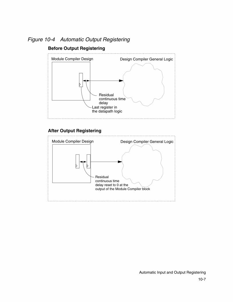
Figure 10-4 Automatic Output Registering
Design Compiler General LogicModule Compiler Design
Residual continuous timedelay
Last register in the datapath logic
Design Compiler General LogicModule Compiler Design
Residual continuous timedelay reset to 0 at theoutput of the Module Compiler block
Before Output Registering
After Output Registering
10-7
Automatic Input and Output Registering
To enable automatic output registering through the Module Compiler GUI, enter the following at the UNIX prompt:
% mcenv dp_register_output +
To disable automatic output registering, enter the following at the UNIX prompt:
% mcenv dp_register_output -
Note: The variable dp_register_input is automatically set to - (minus) because setting it to + (plus) results in the renaming of the input port names, which causes incompatibility with the port names generated during read_mcl.
Input Registering With pipestall, Clear, or Preset
If you enable input registering and set signals through the enable (or pipestall), async_clear, or async_preset directives, you cannot set these directives after your input declarations; if you do, an error will result. This is because the same group cannot have different pipestall, clear, or preset signals.
To correct this error, use separate groups or declare these directives before the input declaration. It is also important to note that the input registers do not have pipestall, clear, or preset signals. The following examples present a problem and give two solutions. Assume for Example 10-1 to Example 10-3 that input registering is enabled.
Example 10-1 Error: Two Different pipestall Signals in a Group
input [8] a; // input registers set to none, in group miscdirective (pipestall = "enab", pipeline = "on") z = a * b; // pipeline registers set to enab, in group misc
10-8
Chapter 10: Module Compiler Pipelining

Example 10-2 Solution: Move pipestall Directive Before Input
// move pipestall directive before inputdirective (pipestall = "enab", pipeline = "on")input [8] a; //input registers set to enab in group miscz = a * b; //pipeline registers set to enab in group misc
Example 10-3 Solution: Use Another Group Solution
input [8] a; // input registers set to none, in group miscdirective (group = "first", pipestall="enab", pipeline="on")z = a * b; //pipeline registers set to enab in group first
Pipelining Flows and Concepts
The following sections discuss the three pipelining flows. You can choose manual pipelining, which uses the preg function; automatic pipelining, which uses the pipeline attribute; or user-specified output latency, which uses the ResolveLatency and ResolveLatencyLoop functions.
Manual Pipelining
For manual pipelining, the preg function provides shift registers built from pipeline registers with a fixed length that is known in advance. This function requires one input, one output, and the integer register length to be passed to it.
When you require access to the shift register taps, for a register of length n, you must pass as many as n + 1 outputs to the function at the end of the parameter list. The first is connected to the input, the second is the output of the first tap, and the last is the output of the nth tap.
10-9
Pipelining Flows and Concepts
Automatic Pipelining
The pipeline attribute enables and disables automatic pipelining. When automatic pipelining is enabled, Module Compiler inserts registers automatically (with a corresponding increase in latency), when the delay goal is exceeded. To control the increase in latency you can use the ResolveLatency and ResolveLatencyLoop commands. For more information, see “Resolving Latency” on page 10-13.
The pipelining is performed in a general and fine-grained (individual instance) level, so any structure can be pipelined automatically. Automatic pipelines can fall inside any structure and work in conjunction with manual pipelines generated by preg.
For additional information, see “Automatic Input and Output Registering” on page 10-4.
User-Specified Output Latency
To enable user-specified output latency, you use the ResolveLatency and ResolveLatencyLoop functions. When you enable user-specified output latency, you can disable pipelining.
Example 10-4 shows how the ResolveLatency function is used to specify an output latency of 2.
Example 10-4 User-Specified Output Latency, ResolveLatency
directive (pipeline="off");input [8] a, b;wire [16] w = a * b;z = ResolveLatency (w, 2); //Z is an output signal
10-10
Chapter 10: Module Compiler Pipelining

Except for pipeline registers introduced by the ResolveLatency function, Module Compiler does not touch other registers when balancing pipeline registers.
You must run register retiming in Design Compiler when you specify output latency without automatic pipelining; otherwise you get poor results. This is because Module Compiler places all registers together at the output of the design. By running retiming, you allow Design Compiler to move registers into your design, which properly balances the pipeline registers across the datapath logic. For more information, see the Design Compiler Reference Manual: Register Retiming. Figure 10-5 shows the placement of registers to balance the pipeline.
Figure 10-5 Retiming to Balance Pipeline Registers
w z
Without Pipeline Retiming
w z
With Pipeline RetimingRegister moved into the design to balance the pipeline
Stages at end of logic
Stages moved into logic
10-11
Pipelining Flows and Concepts

Given that the latency and the delay goal (clock period) are directly related, it is not always possible to meet both goals at the same time when only output latency is specified. After placing the pipeline registers, Design Compiler appropriately balances the registers in the design. As a result of these steps, the delay might not be met for a given latency goal, so the latency goal gets higher priority than the delay goal.
Stalling
You can stall all synthesized flip-flops, whether they are state or pipeline registers, by setting the enable (previously pipestall) attribute to the name of the stall control signal. See “The enable (pipestall) and clockIn Signal Declarations” on page 6-69. By default, the pipeline is not stalled. The pipeline stalls when the stall control signal is low.
Support for ensreg With pipestall
You can use ensreg with enable or pipestall. To use these two together, set the Module Compiler environment variable dp_new_behav_model to + (plus). The default value of this variable is - (minus). Setting dp_new_behav_model to + enables Module Compiler to place registers at the operator boundaries. If this variable is not set to + and if ensreg and pipestall are used together, a gate-to-RTL mismatch can result.
10-12
Chapter 10: Module Compiler Pipelining

Handling Latency
The following sections discuss how to enable pipelining by using the ResolveLatency and ResolveLatencyLoop functions, the eqreg, eqreg1, and eqreg2 equalization functions, and the enable attribute.
The sections include
• Resolving Latency
• User-Specified Input Latency
• Matching Latency
• Pipeline Loaning
Resolving Latency
Both the ResolveLatency and the ResolveLatencyLoop functions set a section of code to a desired latency level. They work with the pipeline directive set to on. Example 10-5 and Example 10-6 give specific usages of these functions.
Example 10-5 ResolveLatency
module resolve1 (Z, A, B); directive(pipeline="on",delay=5000); input [16] A,B; wire [32] Z_temp = A * B; output [32] Z = ResolveLatency (Z_temp, 3);
// user-defined latency of 3 endmodule
10-13
Handling Latency

Example 10-6 ResolveLatencyLoop
module resolve2(Z, A, B); directive(pipeline="on",delay=5000); input [16] A,B; wire [32] Z_temp = A * B; output [32] Z = ResolveLatencyLoop (Z_temp, 4);
// user-defined latency of 4 endmodule
Example 10-5 uses the ResolveLatency function with a specified latency of 3. Example 10-6 uses ResolveLatencyLoop with a specified latency of 4. Using the ResolveLatencyLoop in Example 10-6 results in a registered output (sreg), which does not increase the latency. Both examples result in a latency of 3.
Figure 10-6 shows the summary table after the two examples are run.
Figure 10-6 ResolveLatency* Example Results
In Figure 10-6, the area resulting from the ResolveLatencyLoop example (Example 10-6) is slightly larger than the result from the ResolveLatency example (Example 10-5), because Module Compiler has created an additional sreg with ResolveLatencyLoop.
10-14
Chapter 10: Module Compiler Pipelining

Figure 10-7 and Figure 10-8 show the differences between ResolveLatency and ResolveLatencyLoop. In these diagrams, the cloud represents logic. ResolveLatencyLoop inserts sreg at the end of the pipelined section of code. This sreg does not increase the latency, so the latency between ResolveLatency and ResolveLatencyLoop is the same.
Figure 10-7 Latency for ResolveLatency Example
Use ResolveLatency for a feed-forward path of a design. The latency specified can be 0 or greater. Also, ResolveLatency does not guarantee that the output will be registered.
Figure 10-8 Latency for ResolveLatencyLoop Example
Use the ResolveLatencyLoop functions at the end of a feedback loop. For both of these functions, the desired latency must be specified. For ResolveLatencyLoop, the latency specified can be 1 or greater. Also, ResolveLatencyLoop ensures that the output will be registered.
preg preg preg0 1 2 3 0
counterLatency
value
preg preg preg sreg0 1 2 3 0
counterLatency
value
10-15
Handling Latency

The ResolveLatency and ResolveLatencyLoop functions are covered in more detail in the Module Compiler Reference Manual.
User-Specified Input Latency
Formerly, Module Compiler assumed that all inputs had no (0) latency. You can specify input signals that arrive at different latency levels by using the SetLatency function, which is similar to ResolveLatency. This function works only on input signals and increments only the internal latency counter; it does not create any registers. Accordingly, only the Module Compiler latency counter is incremented. The following example shows how the SetLatency function is used.
input [8] a, b, c;/* assume a has latency=5, b has latency= 2, c has latency=0 */
SetLatency (a, 5); /* now input a to five levels of latency, no FF insertion */
SetLatency (b, 2);/* set input b to two levels of latency, no FF insertion */
/* setting signal c with latency=0 is optional */
SetLatency (c, 0);
For output, Module Compiler pipeline capabilities properly handle the gate-level netlist and the RTL simulation model. When required, Module Compiler ensures that for the gate-level netlists, the signals are properly balanced, as shown in Figure 10-9.
In addition, Module Compiler automatically puts pipelined registers at operator boundaries if SetLatency is used, as shown in Figure 10-10.
10-16
Chapter 10: Module Compiler Pipelining

Figure 10-9 Pipeline Registers at Outputs
Figure 10-10 Pipeline Register at Operator Boundaries
Original design in Module Compiler Language
a
b
z
(0)
(0)
RTL, with no input latency specified
After synthesis and optimization:
*
a
b
z
(0)
(0)*
b has no input latency
1999.10 or Previous Module Compiler Versions
a has no input latency
b has no input latencya has no input latency
RTL, with input latency specifieda has two levels of input latencyb has no input latency
After synthesis and optimization:
a
b
z
(2)
(0)*
Original design in Module Compiler Language
a
b
z a has two levels of input latency
(2)
(0)b has no input latency*
2000.05 or Later Module Compiler Versions
10-17
Handling Latency

Because the registers are at the operator boundaries, the behavioral models look different from when all the pipeline registers are at the output. However, the simulation works as expected.
You must pay attention to the RTL simulation models when you specify input signal latencies in Module Compiler Language. The simulation testbench must offset the number of clock cycles specified as input latencies; otherwise, the simulation fails.
Matching Latency
You use the equalization functions, eqreg, eqreg1, and eqreg2 to build pipeline shift registers with a length determined during synthesis (see Example 10-7). You use the eqreg1 function to achieve a desired latency for a signal.
The function takes the input signal and the desired latency as inputs. You use the eqreg function when the latency of a signal should match the maximum latency from a group of signals. You use the eqreg2 function when the latency of a signal should match the sum of the latencies of a group of signals.
In each case, the function constructs a shift register with the length required to increase the input signal latency to the desired value. If the input latency exceeds the desired latency, an error message is generated during synthesis.
10-18
Chapter 10: Module Compiler Pipelining

Example 10-7 Latency Equalization
X=eqreg(A,3,B,C,D);//length is equal to max(lat(B),lat(C),lat(D)) - lat(A)
X=eqreg1(A,3);//length is equal to 3-lat(A)
X=eqreg2(A,3,B,C,D);//length is equal to lat(B)+lat(C)+lat(D)- lat(A)
X=preg(A,2,B,C,D);//B is A delayed 0, C=A delayed 1, etc
Pipeline Loaning
The pipeline loaning option is based on the concept that certain structures, primarily digital filters of various types, require the input data to be delayed.
The direct implementation uses a state shift register at the input to generate the delayed versions of the input. The inputs and the outputs of the shift registers are then fed into a combinational function for computation of the result.
For symmetric functions, the critical path starts at the input to the shift register. When they are all at the input, the registers are “wasted,” in the sense that they are not being used to break up or isolate the critical paths.
The concept of pipeline loaning is to convert some of the state registers into pipelines that can be used later to improve performance without increasing latency. The first n taps of the shift register are removed. They are replaced by buffers that are later removed by the logic optimizer. This has the net effect of progressively decreasing the latency at each point where a register
10-19
Handling Latency
was replaced, effectively making negative latencies possible. These signals with reduced latency can now be pipelined without an increase in the original latency.
If all the registers are removed from the input, the transposed form seen in many digital signal processing textbooks results. The transposed architecture suffers, in general, from an excessive use of flip-flops to improve performance.
Pipeline loaning allows the architecture to move smoothly between the direct form and the transposed form, without the need to change the network description (except for the parameter n). In addition, because a small value of n generally provides most of the benefit, pipeline loaning results in areas close to that of the direct form and performance close to that of the transposed form.
To use pipeline loaning, write the network description to reflect the direct form. Set the number of stages to loan for pipelining as a parameter. You need to set a reasonable delay goal. For example, don’t optimize for speed, even if pipelining is not enabled. You do not need to enable pipelining, because pipeline loaning requires pipelining for proper operation. If you set the delay goal too low, Module Compiler can quickly use up the pipelines, providing little or no benefit.
The current delay goal determines where Module Compiler places the loaned pipelines. When a result includes all the shift register inputs and outputs, you can set the delay goal to any value, because Module Compiler has completed pipeline loaning.
10-20
Chapter 10: Module Compiler Pipelining
Follow these steps and answer these questions to specify the parameter n:
1. Start with n = 0 and a realistic delay goal.
2. Is the delay goal met?
3. If yes, quit; if not, increment n.
4. Did performance improve?
5. If not, go back to previous n and quit; otherwise, continue.
6. Is n <= len?
7. If yes, go to 2; if not, go back to previous n and quit.
If the outputs of the shift register are the only operands that are connected to the combinational function, such as a fixed coefficient filter or correlator, this technique works transparently.
You need to consider a couple of issues, particularly when other operands enter the function along with the shift register outputs. One case in which this situation occurs is with the variable coefficient FIR filter.
Assume that the coefficients and the shift register input have a latency of 0. The outputs of the shift register now appear to have a negative latency. When the coefficients merge with these negative latency signals at the multiplier, the shift register outputs are delayed to bring them back to latency 0, undoing the entire pipeline loaning. The latency of the coefficients needs to be “hidden” to avoid the latency deskewing.
10-21
Handling Latency

In addition, the latency from the coefficients to the outputs is now different. The latency for the coefficient corresponding to the ith tap of the shift register is as follows:
i if i <= n
n if i > n
This change in latency from the coefficients to the outputs can affect the performance of your algorithm.
Another issue can arise if the signals with decreased latency are not merged with a signal with normal (unadjusted) latency, because the initially requested latency has been removed. For example, an output of the shift register with pipeline loaning can be connected directly to a module output. Module Compiler checks all outputs to see if any “loaned” latency exists and corrects this situation automatically.
These points are illustrated in Figure 10-11. The direct-form implementation of a simple circuit that counts the number of 1s in a data stream is shown first, with all state registers Ss. All signals have a latency of 0. The problem is that the critical signal, DATA IN, is not isolated from the less-critical shift register outputs.
10-22
Chapter 10: Module Compiler Pipelining

Figure 10-11 Direct Form FIR Filter
The pipeline loaning solution is shown in Figure 10-12 for two loaned stages. Note that the first two shift register taps have been removed and the latencies have been adjusted. Now, the least-critical signals (with latency − 2) are summed first. A pipeline register is automatically inserted when the delay exceeds the current delay goal or the signal with latency −1 is encountered.
Note that two pipelines were inserted to replace the state registers that were removed. The latency of the output, DATA OUT, is 0 in both cases. However, if the adder inputs were modified by another signal, such as a coefficient, the latency from the coefficients to the output would now be greater for some taps, because of the inserted pipeline registers.
0
0
DATA IN
DATA OUT
0 0 0 0S S S S
10-23
Handling Latency

Figure 10-12 FIR Filter With Pipeline Loaning
If the delstate attribute were set to 4, you would have the transposed form implementation, with no registers in the input.
If the delstate synthesis attribute of the sreg function is greater than 0, pipeline loaning occurs. To disable pipeline loaning, set delstate back to 0. For more information about the ensreg function, see “State Registers” on page 6-46.
0
0
DATA IN
DATA OUT
-1 -2 -2 -2S S
PP
10-24
Chapter 10: Module Compiler Pipelining

11Using Module Compiler in the Design Compiler Shell 11
This chapter describes how to run Module Compiler in the Design Compiler shell (Tcl mode) to synthesize a design written in Module Compiler Language. This chapter has the following sections:
• Overview of dc_shell
• Enabling Module Compiler in dc_shell
• Setting Up Libraries
• Reading In Module Compiler Language Design Files (read_mcl)
• Setting Constraints Specific to Module Compiler
• Setting dc_shell Constraints
• Synthesizing the Module Compiler Design (compile_mcl)
11-1

• Creating Module Compiler Reports
• Example Script
• Limitations
11-2
Chapter 11: Using Module Compiler in the Design Compiler Shell

Overview of dc_shell
The commands introduced to dc_shell (Tcl mode) for running Module Compiler are as follows:
• read_mcl—Reads in a Module Compiler Language file
• compile_mcl—Synthesizes a Module Compiler Language design
• mcenv—Sets Module Compiler environmental variables
• report_mc—Generates Module Compiler reports
These commands are described in the following few sections. A typical Module Compiler session in dc_shell involves the following steps:
1. Enable the Tcl commands for running Module Compiler in dc_shell
2. Set up link and target libraries
3. Read in Module Compiler Language design files
4. Set design constraints
5. Synthesize the Module Compiler design
6. Generate Module Compiler reports
11-3
Overview of dc_shell
Enabling Module Compiler in dc_shell
To run Module Compiler in dc_shell, use Tcl mode. You do this by running dc_shell-t or dc_shell with the -tcl_mode option at the UNIX prompt.
% dc_shell-t
or
% dc_shell -tcl_mode
Once you are in dc_shell-t, source the mcdc.tcl file that provides the Tcl commands for running Module Compiler. The mcdc.tcl file is in $MCDIR/lib/tcl/mcdc.tcl, where $MCDIR is the root of your Module Compiler release. To source mcdc.tcl, enter the following in dc_shell-t:
dc_shell-t> source [getenv MCDIR]/lib/tcl/mcdc.tcl
Your system administrator can include this command as part of your dc_shell-t startup. For more information, see the Design Compiler dc_shell Tcl documentation.
Setting Up Libraries
You must set up the link and target libraries. Module Compiler uses the target library to synthesize the final design. To set up the link and target libraries, enter the following in dc_shell:
dc_shell-t> set target_library {your_library.db}dc_shell-t> set link_library {your_library.db}
11-4
Chapter 11: Using Module Compiler in the Design Compiler Shell

You can set the search_path variable to specify search paths to the libraries. For example, to set the search path to the current directory (.) and /mydir/myproj/adder, enter the following in dc_shell-t:
dc_shell-t> set search_path {. /mydir/myproj/adder}
Important: When loading technology libraries, it is important that you list the libraries in the order that Module Compiler expects. You must specify the technology file containing the smallest inverter in the library first. Module Compiler defines the technology library with the smallest inverter as the main library. If you do not list the main library first, Module Compiler might exit abnormally and fail to build the pseudocell library, or it might build a suboptimal circuit.
Reading In Module Compiler Language Design Files (read_mcl)
In dc_shell-t, the read_mcl command reads in one or more Module Compiler Language design files and creates an empty design with the Module ports. You can also use the search_path variable to search for Module Compiler files.
Syntaxread_mcl [-par parameters] [-quiet] my_design.mcl
The -par option passes specified parameters to the Module Compiler design. The -quiet option reduces the number of messages the command generates.
11-5
Reading In Module Compiler Language Design Files (read_mcl)

Example
Use the read_mcl command in Design Compiler to read in a Module Compiler Language design. For example,
dc_shell-t> read_mcl mc_design.mcl -par width=4,arch=0
If you need to read in more than one Module Compiler Language file, use either of the following options in dc_shell-t.
dc_shell-t> read_mcl -par taps=6 {fir.mcl firfx.mcl}
or
dc_shell-t> read_mcl -par taps=6 [list fir.mcl firfx.mcl]
Setting Constraints Specific to Module Compiler
You can set constraints specific to Module Compiler by using the mcenv utility. Module Compiler initially invokes with default settings. Set Module Compiler environment variables after reading in a Module Compiler Language file (with the read_mcl filename.mcl command) and before running the compile_mcl command. Module Compiler uses the resulting settings when compiling the file you specified. Use dc_shell-t commands to set other constraints.
You can use the Module Compiler mcenv command in dc_shell-t to set Module Compiler variables. For example, to set the output language to VHDL, enter the following in dc_shell:
dc_shell-t> mcenv dp_lang_out vhdl
11-6
Chapter 11: Using Module Compiler in the Design Compiler Shell

When running Module Compiler in the Design Compiler shell (Tcl mode), consider the following guidelines:
• The mc.env file is not used when Module Compiler is run from dc_shell. (The mc.env file is used when Module Compiler is stand-alone.)
• Any mc.env file in the run directory is deleted. Therefore, you should make sure to move from the run directory any mc.env file that you want to keep.
• Not all dc_shell constraints are supported when running Module Compiler in the Design Compiler Tcl shell.
Setting dc_shell Constraints
In dc_shell-t, Module Compiler recognizes the settings of the wire load model and the operating condition. Module Compiler supports the settings of the following dc_shell commands:
set_wire_load_modelset_operating_conditions
Here are some sample usages of these commands:
dc_shell-t> set_wire_load_model -name block20x20dc_shell-t> set_operating_conditions WCCOM
In addition, you can specify Synopsys Design Constraints (SDC) to a Module Compiler Language design. The SDC commands Module Compiler supports are
11-7
Setting dc_shell Constraints

create_clockset_input_delayset_output_delayset_max_capacitanceset_load
For more information about Module Compiler SDC support, see Chapter 12, “Synopsys Design Constraints.”
To apply the dont_use attribute to library cells, use the set_dont_use command. Module Compiler automatically creates a new properties file based on the following settings:
dc_shell-t>set_dont_use {tech_lib/cell_A,tech-lib/cell_B}
The dp_prop_fname variable, specified by the user, is not available during compilation.
Synthesizing the Module Compiler Design (compile_mcl)
The compile_mcl command synthesizes and optimizes a design created with read_mcl. This compiled design is automatically loaded into dc_shell as the current design.
Syntaxcompile_mcl [-quiet]
The -quiet option reduces the number of messages the command generates.
11-8
Chapter 11: Using Module Compiler in the Design Compiler Shell

Example
To compile the Module Compiler Language file specified previously by the read_mcl command, enter the following in Design Compiler shell:
dc_shell-t> compile_mcl
Creating Module Compiler Reports
In dc_shell-t, use the report_mc command to generate Module Compiler reports. Unlike with Module Compiler stand-alone, no information is written to the current directory.
The dc_shell-t Module Compiler report options are listed below.
You can save the log or report into a file by using the redirection (>) command.
dc_shell-t> report_mc -log > my_log_file.txt
Command Report
report_mc -log Module Compiler log file
report_mc - report Module Compiler design report file
report_mc -lib Module Compiler library report file
11-9
Creating Module Compiler Reports

Example Script
The following set of examples shows how to run Module Compiler in Design Compiler shell (Tcl mode) to synthesize a design written in Module Compiler Language. A Module Compiler Language design named add.mcl (Example 11-1) is used in a dc_shell script (Example 11-2), which generates a output log report (Example 11-3).
Example 11-1 add.mcl
module add (a,b,z,width,fa); integer width=8; string fa ="cla"; input [width] a,b; output [width+1] z; directive (clock="clk1",fatype=fa); z = a + b; endmodule
Example 11-2 is a script that runs Module Compiler in dc_shell, sets constraints on the add.mcl design, and compiles it. This script does the following:
• Sources the mcdc.tcl file to enable Tcl to enable Module Compiler in dc_shell
• Sets up the search path and libraries
• Reads in a Module Compiler Language design file
• Sets design constraints
• Compiles the Module Compiler design
• Generates Module Compiler reports
11-10
Chapter 11: Using Module Compiler in the Design Compiler Shell
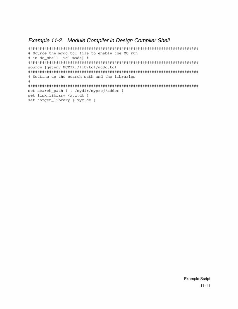
Example 11-2 Module Compiler in Design Compiler Shell########################################################################## Source the mcdc.tcl file to enable the MC run # in dc_shell (Tcl mode) # #########################################################################source [getenv MCDIR]/lib/tcl/mcdc.tcl########################################################################## Setting up the search path and the libraries # #########################################################################set search_path { . /mydir/myproj/adder } set link_library {xyz.db } set target_library { xyz.db }
11-11
Example Script

########################################################################## Reading in the MCL file # #########################################################################read_mcl add.mcl -par width=4,fa=fastcla########################################################################## Setting up the constraints # #########################################################################set_wire_load_model -name B5X5 set_operating_conditions WCCOMcreate_clock -name clk1 -period 3.0 set_max_capacitance 0.616 {a b} set_load 0.308 z set_output_delay 1.5 z -clock clk1mcenv dp_register_output + mcenv dp_lang_out verilog mcenv dp_bver_name add.bvreport_port######################################################################### Compiling the datapath block using MC # ########################################################################compile_mcl -quiet######################################################################### Generating reports # ########################################################################report_mc -log > add.log report_mc -report > add.report report_mc -lib > xyz.report ########################################################################
11-12
Chapter 11: Using Module Compiler in the Design Compiler Shell

Log File Generated From Example Script
Example 11-3 is the Design Compiler log file generated when the script in Example 11-2 is run.
Example 11-3 Design Compiler Log File########################################################################## Source the mcdc.tcl file to enable the Module Compiler run in dc_shell (Tcl mode) #########################################################################source [getenv MCDIR]/lib/tcl/mcdc.tcl ########################################################################## Setting up the search path and the libraries # #########################################################################set search_path { . /mydir/myproj/adder} . /mydir/myproj/adder set link_library { xyz.db } xyz.db set target_library { xyz.db } xyz.db ########################################################################## Reading in the Module Compiler Language file # #########################################################################read_mcl add.mcl -par width=4,fa=fastcla Reading Module Compiler File... Please wait... Synopsys Module Compiler (TM) (MC) 2000.05 Copyright (C) 1992-1999 Synopsys.Preprocessor Copyright (C) 1986 Free Software Foundation, Inc. Using MC library at: /mydir/project/tech Using MC at: /mcdir/root/mc Reading `/mcdir/root/mc/lib/dp//db.tech' Requesting license: MC-Pro ... Trying Floating: MC-Pro 2000.05 ... Success! Checked out: MC-Pro 2000.05Validating libraries ... tcl logo dplib ramlib fifolib alulib memlib arithlib genra mlib gfxlib fplib generic_lib flatlib ... ok
11-13
Example Script

***********************************Initializing***************************** ******Technology Lib Dir: /mydir/project/tech Technology: xyz Reading Generic Library ... /mcdir/root/mc/lib/dp/generic.scdf Reading Technology Library(s) ... /mydir/myproj/adder/xyz.db Reading Pseudo Cell Libraries ... ./pcelllocallib/B0X0/NOM/synlib.xyz.scdf ./pcelllocallib/B0X0/NOM/synlib.xyz.edif Reading User Libraries ... Generating Optimization Libraries ... Writing Cell Defs ...Writing library information *****************************Initializing Completed***************************** Operating Condition Set Condition: NOM Temperature: 25 Voltage: 3.30 Wireload Model: B0X0 Tree Type: balanced_treeCurrent design is add ########################################################################## Setting up the constraints # #########################################################################set_wire_load_model -name B5X5 Design add: Using wire_load model 'B5X5' found in library 'xyz_scaled_wcindv'. 1 set_operating_conditions WCCOM Using operating conditions 'WCCOM' found in library 'xyz_scaled_wcindv'.1 create_clock -name clk1 -period 4.0 Warning: Creating virtual clock named 'clk1' with no sources. (UID-348) 1 set_max_capacitance 0.616 {a b} 1 set_load 0.308 z 1 set_output_delay 1.5 z -clock clk1 1
11-14
Chapter 11: Using Module Compiler in the Design Compiler Shell
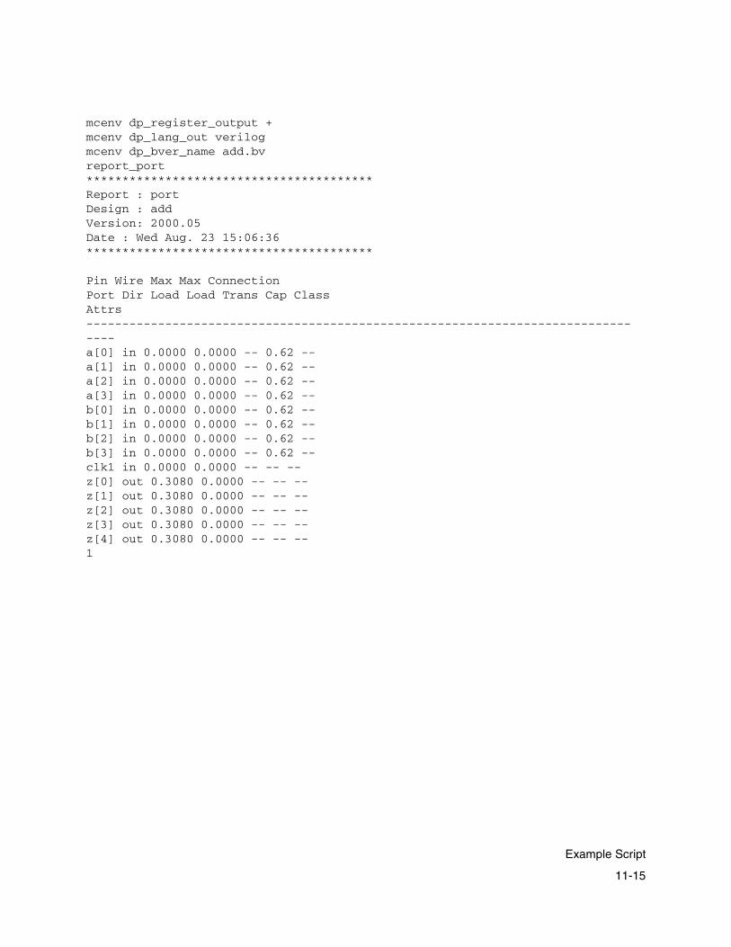
mcenv dp_register_output + mcenv dp_lang_out verilog mcenv dp_bver_name add.bv report_port**************************************** Report : port Design : add Version: 2000.05 Date : Wed Aug. 23 15:06:36****************************************
Pin Wire Max Max Connection Port Dir Load Load Trans Cap Class Attrs ---------------------------------------------------------------------------- ----a[0] in 0.0000 0.0000 -- 0.62 -- a[1] in 0.0000 0.0000 -- 0.62 -- a[2] in 0.0000 0.0000 -- 0.62 -- a[3] in 0.0000 0.0000 -- 0.62 -- b[0] in 0.0000 0.0000 -- 0.62 -- b[1] in 0.0000 0.0000 -- 0.62 -- b[2] in 0.0000 0.0000 -- 0.62 -- b[3] in 0.0000 0.0000 -- 0.62 -- clk1 in 0.0000 0.0000 -- -- -- z[0] out 0.3080 0.0000 -- -- -- z[1] out 0.3080 0.0000 -- -- -- z[2] out 0.3080 0.0000 -- -- -- z[3] out 0.3080 0.0000 -- -- -- z[4] out 0.3080 0.0000 -- -- --1
11-15
Example Script
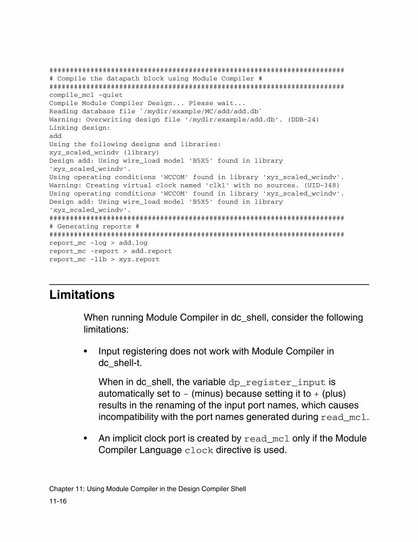
######################################################################### Compile the datapath block using Module Compiler #########################################################################compile_mcl -quiet Compile Module Compiler Design... Please wait...Reading database file `/mydir/example/MC/add/add.db` Warning: Overwriting design file '/mydir/example/add.db'. (DDB-24) Linking design: add Using the following designs and libraries: xyz_scaled_wcindv (library) Design add: Using wire_load model 'B5X5' found in library 'xyz_scaled_wcindv'. Using operating conditions 'WCCOM' found in library 'xyz_scaled_wcindv'.Warning: Creating virtual clock named 'clk1' with no sources. (UID-348) Using operating conditions 'WCCOM' found in library 'xyz_scaled_wcindv'.Design add: Using wire_load model 'B5X5' found in library 'xyz_scaled_wcindv'. ######################################################################### Generating reports #########################################################################report_mc -log > add.log report_mc -report > add.report report_mc -lib > xyz.report
Limitations
When running Module Compiler in dc_shell, consider the following limitations:
• Input registering does not work with Module Compiler in dc_shell-t.
When in dc_shell, the variable dp_register_input is automatically set to - (minus) because setting it to + (plus) results in the renaming of the input port names, which causes incompatibility with the port names generated during read_mcl.
• An implicit clock port is created by read_mcl only if the Module Compiler Language clock directive is used.
11-16
Chapter 11: Using Module Compiler in the Design Compiler Shell
• You cannot use the Module Compiler parameter iteration file in dc_shell-t. Instead, you can use the programming capability of Tcl to perform parameter iteration.
• You cannot run Module Compiler in GUI mode in dc_shell-t.
• The mc.env file is not used for the Module Compiler run in dc_shell-t, and any existing mc.env file in the run directory is deleted. Therefore, you must use the mcenv command in dc_shell-t.
• There is an interoperability limitation for cell naming within any technology library. There cannot be a leading “.” in the cell name. This limitation is for the first character only. A “.” can occur after the first letter of the cell name.
11-17
Limitations

11-18
Chapter 11: Using Module Compiler in the Design Compiler Shell

12Synopsys Design Constraints 12
This chapter includes the following sections:
• Overview of Synopsys Design Constraints
• Using SDC With Module Compiler
• Precedence Order for Constraints
• Bitwise Constraints on Input and Output Ports
• Checking Reports of Constraints Used by Module Compiler
12-1
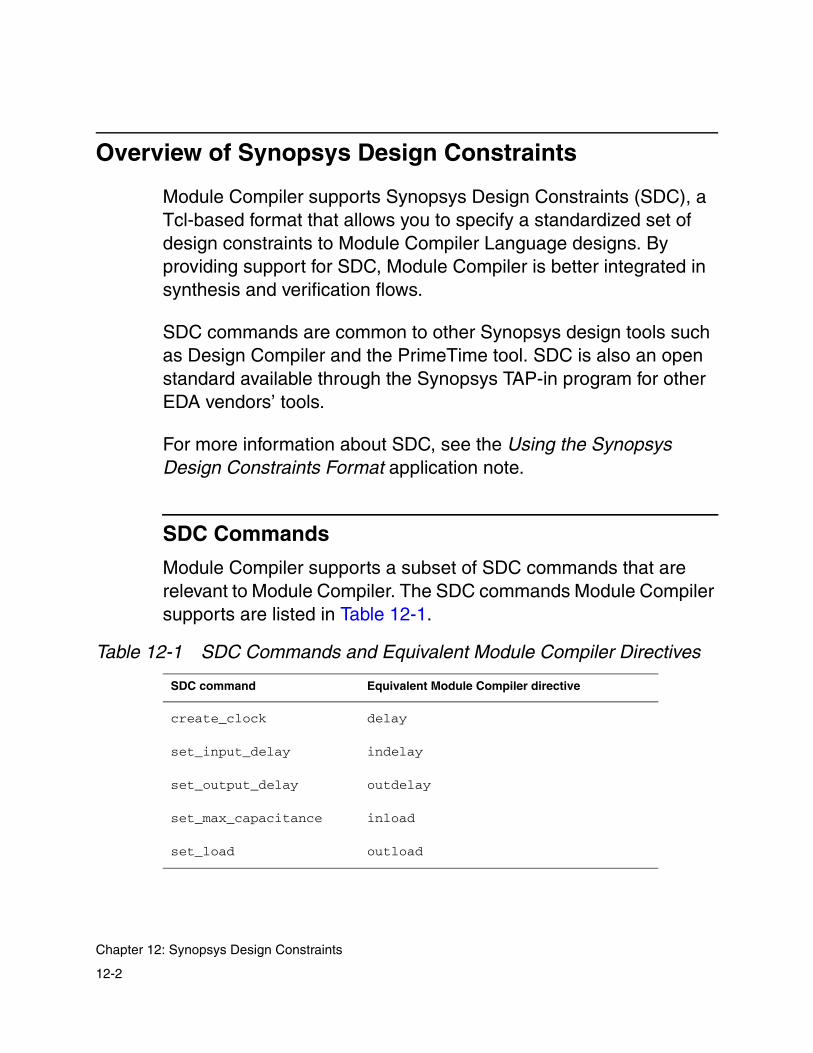
Overview of Synopsys Design Constraints
Module Compiler supports Synopsys Design Constraints (SDC), a Tcl-based format that allows you to specify a standardized set of design constraints to Module Compiler Language designs. By providing support for SDC, Module Compiler is better integrated in synthesis and verification flows.
SDC commands are common to other Synopsys design tools such as Design Compiler and the PrimeTime tool. SDC is also an open standard available through the Synopsys TAP-in program for other EDA vendors’ tools.
For more information about SDC, see the Using the Synopsys Design Constraints Format application note.
SDC Commands
Module Compiler supports a subset of SDC commands that are relevant to Module Compiler. The SDC commands Module Compiler supports are listed in Table 12-1.
Table 12-1 SDC Commands and Equivalent Module Compiler Directives
SDC command Equivalent Module Compiler directive
create_clock delay
set_input_delay indelay
set_output_delay outdelay
set_max_capacitance inload
set_load outload
12-2
Chapter 12: Synopsys Design Constraints

The following examples show the equivalence between the Module Compiler Language directives and their corresponding SDC commands. Example 12-1 shows a Module Compiler Language file (test1.mcl) in which constraints are specified by use of Module Compiler Language directives.
Example 12-1 Constraints Specified With Module Compiler Language Directives
module mult (A,B Z);directive (delay=5000,clock="CLK1");directive (indelay=1000, outdelay=1500);input[32] A,B;output[64] Z=A*B;endmodule
Instead of using Module Compiler Language directives, you can apply the same constraints by using SDC commands as shown in Example 12-2 and Example 12-3.
Example 12-2 module mult Without Using Directives (test2.mcl)
module mult (A,B Z);input[32] A,B;output[64] Z=A*B;endmodule
Example 12-3 Equivalent Constraints Specified to a DesignWith SDC Commands
dc_shell-t> read_mcl test2.mcldc_shell-t> create_clock -name CLK1 -period 5.0dc_shell-t> set_input_delay 1.0 [all_inputs()] -clock CLK1dc_shell-t> set_output_delay 1.5 Zdc_shell-t> compile_mcl
12-3
Overview of Synopsys Design Constraints
SDC Units
SDC uses the units found in your technology library. Consider the following SDC commands used for constraining a certain design.
Example 12-4 SDC Using Units From the Technology Library
create_clock -name CLK1 -period 5.0set_max_capacitance 2.56 A[0]
In Example 12-4, if the unit of time specified in the technology library is nanoseconds, the create_clock SDC command uses a clock that has a period of 5 ns. If the unit is picoseconds, the clock used for the design has a period of 5 ps.
Similarly, if the unit of capacitance specified in the technology library is picofarads (pF), the set_max_capacitance command sets an inload of 2.56 pF on bit 0 of signal A. By using SDC commands, you can set bitwise constraints on a signal. For more information, see “Bitwise Constraints on Input and Output Ports” on page 12-10.
12-4
Chapter 12: Synopsys Design Constraints
Using SDC With Module Compiler
You can use SDC with Module Compiler in the following two cases:
• When Module Compiler is used from within dc_shell
• When Module Compiler is used by itself (Module Compiler stand-alone)
Using SDC With Module Compiler Within thedc_shell Environment
You can launch Module Compiler from within dc_shell by using the read_mcl and compile_mcl commands.
With SDC support, you can specify constraints to Module Compiler Language designs by using commands common to SDC and Design Compiler. This provides the following advantages:
• You can use all the control structure shell commands provided in the Tcl mode of dc_shell. They include if, switch, foreach, while, for, break, and continue.
• You can use object access commands in dc_shell. Object access commands such as all_inputs(), all_outputs(), and get_ports() make it convenient for you to specify arguments to the SDC commands.
12-5
Using SDC With Module Compiler
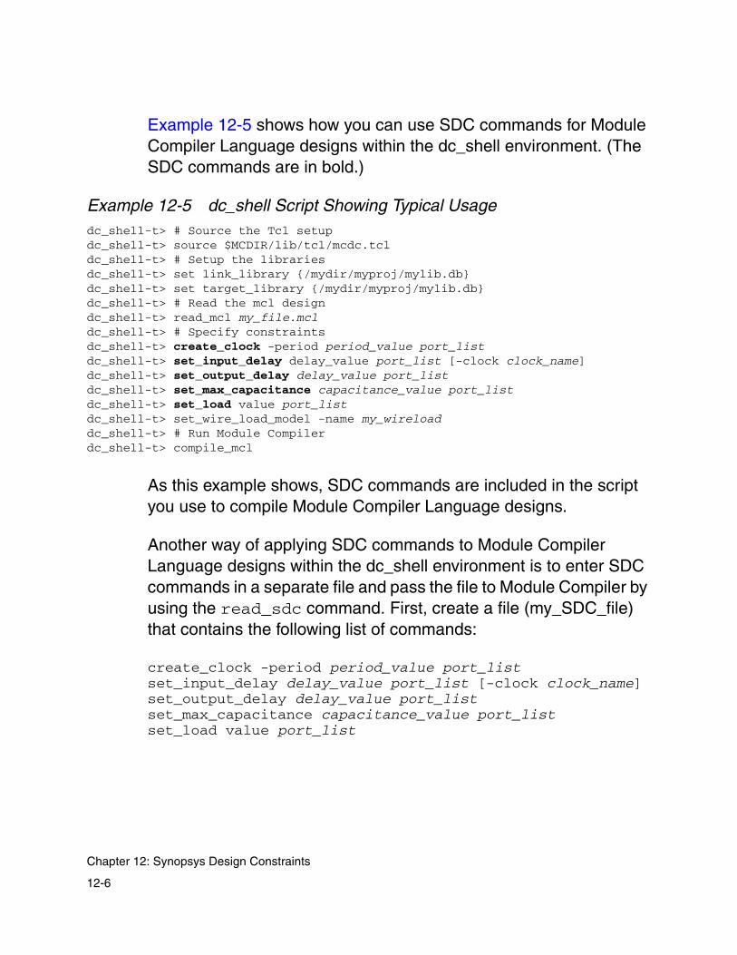
Example 12-5 shows how you can use SDC commands for Module Compiler Language designs within the dc_shell environment. (The SDC commands are in bold.)
Example 12-5 dc_shell Script Showing Typical Usagedc_shell-t> # Source the Tcl setupdc_shell-t> source $MCDIR/lib/tcl/mcdc.tcldc_shell-t> # Setup the librariesdc_shell-t> set link_library {/mydir/myproj/mylib.db}dc_shell-t> set target_library {/mydir/myproj/mylib.db}dc_shell-t> # Read the mcl designdc_shell-t> read_mcl my_file.mcldc_shell-t> # Specify constraintsdc_shell-t> create_clock -period period_value port_listdc_shell-t> set_input_delay delay_value port_list [-clock clock_name]dc_shell-t> set_output_delay delay_value port_listdc_shell-t> set_max_capacitance capacitance_value port_listdc_shell-t> set_load value port_listdc_shell-t> set_wire_load_model -name my_wireloaddc_shell-t> # Run Module Compilerdc_shell-t> compile_mcl
As this example shows, SDC commands are included in the script you use to compile Module Compiler Language designs.
Another way of applying SDC commands to Module Compiler Language designs within the dc_shell environment is to enter SDC commands in a separate file and pass the file to Module Compiler by using the read_sdc command. First, create a file (my_SDC_file) that contains the following list of commands:
create_clock -period period_value port_listset_input_delay delay_value port_list [-clock clock_name]set_output_delay delay_value port_listset_max_capacitance capacitance_value port_listset_load value port_list
12-6
Chapter 12: Synopsys Design Constraints

Then apply these constraints to your Module Compiler Language design (my_file.mcl), by using the commands shown in Example 12-6.
Example 12-6 SDC Commands to Designs Using read_sdc
dc_shell-t> read_mcl my_file.mcldc_shell-t> read_sdc my_SDC_filedc_shell-t> set_wire_load_model -name my_wireloaddc_shell-t> compile_mcl
Example 12-5 and Example 12-6 show two ways of applying the same set of SDC commands to the my_file.mcl design.
Using SDC With Module Compiler Stand-Alone
You can pass an SDC constraints file as an argument to Module Compiler by using the -sdc command-line option or by setting the dp_sdc_in Module Compiler environment variable. The SDC file you pass to Module Compiler must be in the Synopsys .db format.
To set the -sdc command-line option, enter the following at the UNIX prompt:
% mc -sdc Synopsys_Design_Constraints_Filename
This sets Module Compiler to run with the SDC constraints specified in the named SDC constraints file.
Another way of specifying an SDC file to Module Compiler stand-alone is to set the dp_sdc_in Module Compiler environment variable to the SDC file name. The default for dp_sdc_in is -. To set the dp_sdc_in Module Compiler environment variable, enter the following at the UNIX prompt:
% mcenv dp_sdc_in Synopsys_Design_Constraints_Filename
12-7
Using SDC With Module Compiler
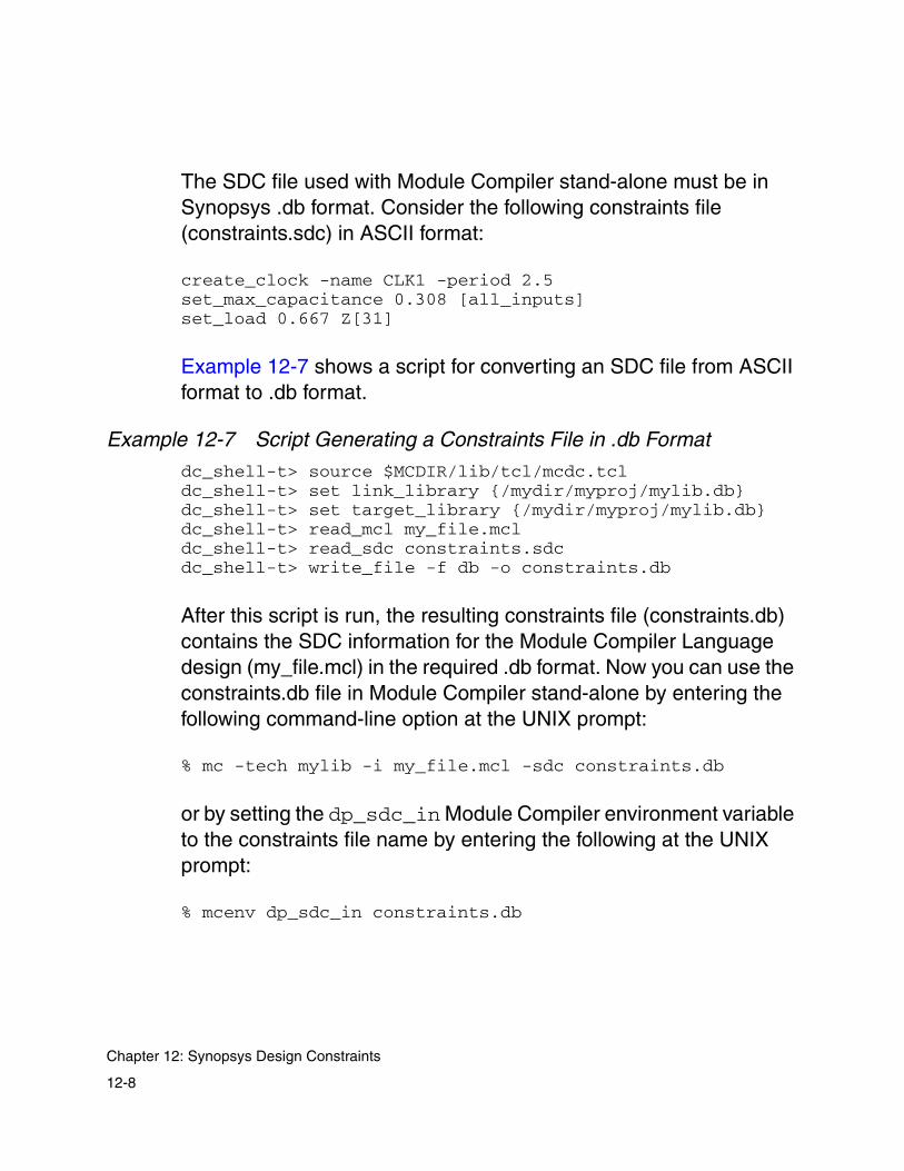
The SDC file used with Module Compiler stand-alone must be in Synopsys .db format. Consider the following constraints file (constraints.sdc) in ASCII format:
create_clock -name CLK1 -period 2.5set_max_capacitance 0.308 [all_inputs]set_load 0.667 Z[31]
Example 12-7 shows a script for converting an SDC file from ASCII format to .db format.
Example 12-7 Script Generating a Constraints File in .db Format
dc_shell-t> source $MCDIR/lib/tcl/mcdc.tcldc_shell-t> set link_library {/mydir/myproj/mylib.db}dc_shell-t> set target_library {/mydir/myproj/mylib.db}dc_shell-t> read_mcl my_file.mcldc_shell-t> read_sdc constraints.sdcdc_shell-t> write_file -f db -o constraints.db
After this script is run, the resulting constraints file (constraints.db) contains the SDC information for the Module Compiler Language design (my_file.mcl) in the required .db format. Now you can use the constraints.db file in Module Compiler stand-alone by entering the following command-line option at the UNIX prompt:
% mc -tech mylib -i my_file.mcl -sdc constraints.db
or by setting the dp_sdc_in Module Compiler environment variable to the constraints file name by entering the following at the UNIX prompt:
% mcenv dp_sdc_in constraints.db
12-8
Chapter 12: Synopsys Design Constraints

Precedence Order for Constraints
There are several ways to specify constraints to Module Compiler Language designs. You can specify constraints through SDC commands, Module Compiler Language directives, or Module Compiler environment variables.
When you specify constraints, Module Compiler follows the following order of precedence for the constraint values:
• SDC commands (highest precedence)
• Module Compiler Language directives (intermediate precedence)
• Module Compiler environment variables (lowest precedence)
The precedence order applies only to conflicting values for the same constraint. You can specify nonconflicting constraint values through SDC commands in addition to the constraints you specify in the Module Compiler Language file or in the mc.env file.
Consider a situation in which conflicting constraint values are applied to module add as shown in Example 12-8 and Example 12-9.
Example 12-8 Constraints Specified to module add, Using Directives
module add (A,B,Z)directive (delay=5000,clock="CLK1");input[32]A,B;output[33]Z=A+B;endmodule
12-9
Precedence Order for Constraints

Example 12-9 Constraints Applied to module add, Using SDC in dc_shell-t
dc_shell-t> read_mcl add.mcldc_shell-t> create_clock -name CLK1 -period 2.0dc_shell-t> compile_mcl
In this case, there are two conflicting values of clock period for the same clock, CLK1. Here, the value of 2.0 ns set by the create_clock SDC command overrides the delay value of 5.0 ns (5,000 ps) set by the Module Compiler Language directive. This shows that SDC commands take precedence over Module Compiler Language directives.
Bitwise Constraints on Input and Output Ports
In earlier Module Compiler versions, you could set constraints only at the signal level by using directives. For example,
directive (indelay=1000);input [4] A;
This implies that all the bits of input signal A have a delay value of 1 ns. With Module Compiler version 2001.08, you can specify bit-level delay by using SDC commands.
12-10
Chapter 12: Synopsys Design Constraints
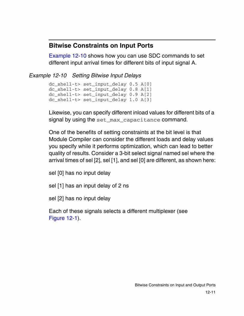
Bitwise Constraints on Input Ports
Example 12-10 shows how you can use SDC commands to set different input arrival times for different bits of input signal A.
Example 12-10 Setting Bitwise Input Delays
dc_shell-t> set_input_delay 0.5 A[0]dc_shell-t> set_input_delay 0.8 A[1]dc_shell-t> set_input_delay 0.9 A[2]dc_shell-t> set_input_delay 1.0 A[3]
Likewise, you can specify different inload values for different bits of a signal by using the set_max_capacitance command.
One of the benefits of setting constraints at the bit level is that Module Compiler can consider the different loads and delay values you specify while it performs optimization, which can lead to better quality of results. Consider a 3-bit select signal named sel where the arrival times of sel [2], sel [1], and sel [0] are different, as shown here:
sel [0] has no input delay
sel [1] has an input delay of 2 ns
sel [2] has no input delay
Each of these signals selects a different multiplexer (see Figure 12-1).
12-11
Bitwise Constraints on Input and Output Ports

Figure 12-1 Bitwise Constraints on Inputs
In this case, because it is known that sel [1] arrives late, the output Z cannot be calculated in less than 2 ns. Module Compiler usually optimizes adders for speed; however, because sel [1] arrives late, Module Compiler can optimize the adders for area, which can lead to better QoR.
Bitwise Constraints on Output Ports
Bitwise values of delay and load can also be applied to the output ports by use of the set_output_delay and set_load commands. However, for output ports, Module Compiler uses the worst-case bit value for the entire bus. Consider a 4-bit output signal Z where the load values are different, as shown in Example 12-11.
sel [2]
sel [0]
sel [1]
Z
+
+
AB
~A~B
ABAB
(input delay: 0)
(input delay: 2)
(input delay: 0)
12-12
Chapter 12: Synopsys Design Constraints
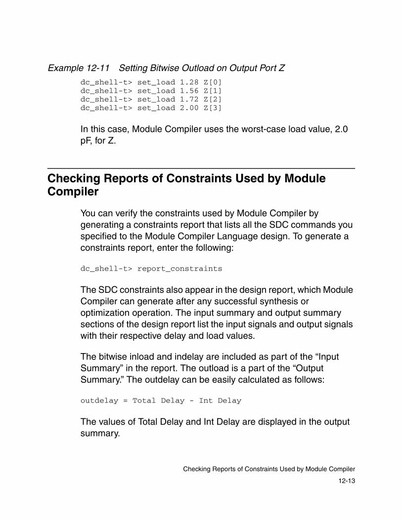
Example 12-11 Setting Bitwise Outload on Output Port Z
dc_shell-t> set_load 1.28 Z[0]dc_shell-t> set_load 1.56 Z[1]dc_shell-t> set_load 1.72 Z[2]dc_shell-t> set_load 2.00 Z[3]
In this case, Module Compiler uses the worst-case load value, 2.0 pF, for Z.
Checking Reports of Constraints Used by Module Compiler
You can verify the constraints used by Module Compiler by generating a constraints report that lists all the SDC commands you specified to the Module Compiler Language design. To generate a constraints report, enter the following:
dc_shell-t> report_constraints
The SDC constraints also appear in the design report, which Module Compiler can generate after any successful synthesis or optimization operation. The input summary and output summary sections of the design report list the input signals and output signals with their respective delay and load values.
The bitwise inload and indelay are included as part of the “Input Summary” in the report. The outload is a part of the “Output Summary.” The outdelay can be easily calculated as follows:
outdelay = Total Delay - Int Delay
The values of Total Delay and Int Delay are displayed in the output summary.
12-13
Checking Reports of Constraints Used by Module Compiler

12-14
Chapter 12: Synopsys Design Constraints

13Clock Gating 13
This chapter includes the following sections:
• Licenses and Flows
• Using Module Compiler Clock Gating in dc_shell
• Using Module Compiler Netlist for Power Compiler
13-1
Licenses and Flows
Module Compiler works with the Power Compiler tool to perform clock gating to reduce power consumption on a design in Module Compiler Language.
You should have some familiarity with Power Compiler and Design Compiler before running this flow.
Required Licenses for Module Compiler Clock Gating
To perform clock gating with Module Compiler you need licenses for the following tools:
• Module Compiler
• Design Compiler
• Power Compiler
Supported Clock-Gating Flows
Module Compiler has two clock-gating flows:
• Module Compiler within dc_shell
• Module Compiler-created netlist
These flows are discussed in more detail in the following sections.
13-2
Chapter 13: Clock Gating
Using Module Compiler Clock Gating in dc_shell
This section covers the steps for running Module Compiler clock gating.
To run Module Compiler clock gating in dc_shell, first run dc_shell in Tcl mode. See Chapter 11, “Using Module Compiler in the Design Compiler Shell,” for more details.
Follow these steps:
1. In dc_shell-t (Tcl mode), you can use the read_mcl command to read in a design written in Module Compiler Language. After reading in a design, set the current design and the design constraints.
2. Set the Module Compiler clock-gating option by using the mcenv dp_clockgating command. To enable Module Compiler clock gating, enter the following at the dc_shell-t prompt:
dc_shell-t> mcenv dp_clockgating +
3. Run the compile_mcl command to create unmapped sequential cells for Power Compiler to use when performing clock gating.
For more information about the read_mcl and compile_mcl commands, see Chapter 11, “Using Module Compiler in the Design Compiler Shell.”
4. Use the set_clock_gating_style command, which is needed for the insert_clock_gating command to work. For more information on the set_clock_gating_style command, see the Power Compiler Reference Manual and the man pages.
13-3
Using Module Compiler Clock Gating in dc_shell

5. Optionally, run the set_clock_gating_registers command. This command is used to explicitly control which registers are gated by Power Compiler, overriding the selection dictated by the set_clock_gating_style command. For more information on this command, see the Power Compiler Reference Manual.
6. After creating unmapped sequential cells, set up the clock-gating style and perform clock gating with Power Compiler by using the insert_clock_gating command. This step restructures the circuit for clock gating but does not translate unmapped sequential cells to technology cells.
7. After you perform clock gating, a report is displayed that shows the number of registers successfully clock-gated. For more information on the potential power savings from clock gating, see the Power Compiler Reference Manual.
8. You must execute the propagate_constraints -gate_clock command before running compile. The propagate_constraints -gate_clock command ensures that top-level constraints are passed to subblocks in a hierarchical design (such as a mixed RTL and Module Compiler Language design).
It is important to note that because Module Compiler designs are flat, without hierarchy, this command might not be required in a dc_shell-t based flow that has only Module Compiler Language designs.
9. Next, run uniquify and compile -incremental_mapping commands on your design. You run uniquify because clock gating creates hierarchical cells that must be made unique before compiling. You run the compile -incremental_mapping command to map unmapped cells to technology cells.
13-4
Chapter 13: Clock Gating

Although a standard Module Compiler netlist is flat, having no levels of hierarchy, a Module Compiler clock-gating flow with Power Compiler introduces hierarchy for the clock-gating cells.
10. You can optionally flatten the netlist during the compile -incr step, but this hierarchy might be useful for downstream tools. For example, you might want to identify clock-gating cells by their hierarchical names for the place and route flow. Therefore, it is strongly recommended that you retain the hierarchy added by the clock-gating cells and do not flatten the netlist.
Figure 13-1 describes the results after you run the insert_clock_gating and compile -incremental_mapping commands.
Note: Beginning with the V-2003.12 release, Power Compiler no longer requires you to use the -mc option with the insert_clock_gating command.
13-5
Using Module Compiler Clock Gating in dc_shell

Figure 13-1 Running the compile_mcl Command
You can determine the power savings from Module Compiler clock gating by using the Power Compiler analysis and reporting tools. For more information, see the Power Compiler documentation.
After compile_mcl
D
EN
CLK
QUnmappedsequential
After you run insert_clock_gating and
D
CLK
EN
QMapped
cell
Clock-gating cell
Inserted by Power Compiler
cell
can occur (see the Power Compiler documentation for the mostup-to-date information).
compile -incremental_mapping,the following
13-6
Chapter 13: Clock Gating

Example 13-1 is a sample script showing usage of Module Compiler clock gating in dc_shell-t:
Example 13-1 Integrated Clock-Gating Flow dc_shell-t Script
# set up library (link_library, target_library, etc.)############################################## source setup.tcl############################################## # Read in Module Compiler Language files##############################################read_mcl my_design.mcl -par del=3000,w=4current_design mydesignset_wire_load_mode topset_wire_load_model -name B5X5set_operating_conditions WCCOM################################################### Turn on Module Compiler clock-gating using mcenv command##################################################mcenv dp_clockgating +################################################### Compile Module Compiler Language to produce # a design with unmapped sequential cells##################################################compile_mcl################################################### Set up clock gating style and perform clock gating in Power # Compiler. This step is mandatory.##################################################set_clock_gating_style#set_clock_gating_style -seq none#set_clock_gating_style -positive_edge integrated ################################################### Optionally use set_clock_gating_registers command # to explicitly control which registers (I26, I25, I24,...)# are clock-gated by the insert_clock_gating -mc command# This will override the selection guided by the # set_clock_gating_style command################################################### set_clock_gating_registers -include_instances \{"I26", "I25", "I24", "I23", "I6", "I5", "I4", "I3"}
13-7
Using Module Compiler Clock Gating in dc_shell

################################################### Perform clock gating##################################################insert_clock_gating###################################################Clock gating creates hierarchical cells that must be#uniquified before compiling. Also propagate constraints.##################################################current_design my_designpropagate_constraints -gate_clockuniquifycompile -incremental_mappinglinkreport_timing > timing.rptreport_qor > qor.rptreport_clock_gating > clkgating.rptwrite -f verilog -o mydesign_dc.vrlquit# compile maps unmapped cells to technology library
Using Module Compiler Netlist for Power Compiler
The Module Compiler netlist for Power Compiler flow requires the generation of a netlist in .db format. You can generate the .db in the Module Compiler GUI or by running Module Compiler in dc_shell-t. This netlist in .db format is then read into dc_shell to perform clock gating with Power Compiler.
Note that you cannot use the Verilog or VHDL netlist created by Module Compiler when you turn on clock gating with the Module Compiler environment variable dp_clockgating + or -cg + option in the Module Compiler-generated netlist flow.
Although these netlists might reflect behavioral changes, the netlists do not have the information necessary for successful clock gating of your Module Compiler Language design. If you try to use a Verilog or VHDL netlist, Module Compiler will issue a warning message.
13-8
Chapter 13: Clock Gating

For successful clock gating of a Module Compiler Language design, you must use a .db file written from Module Compiler for further clock- gating processing by Power Compiler. However, writing out a .db file is not necessary for using Module Compiler clock gating in dc_shell.
The steps for running Module Compiler clock gating are shown below:
1. Enable the generation of the .db netlist; set the Module Compiler environment variable dp_db_out to +.
% mcenv dp_db_out +
Alternatively, you can include the -db + command-line option when running Module Compiler from the command line.
% mc -tech mytech -i mydesign.mcl -cg + -db + &
2. The .db netlist created by Module Compiler is postprocessed by Power Compiler and Design Compiler to clock-gate the registers.
You control Module Compiler clock gating by using the mcenv dp_clockgating command. To enable Module Compiler clock gating, enter the following at the UNIX prompt:
% mcenv dp_clockgating +
Alternatively, you can include the -cg + command-line option when running Module Compiler from the command line:
% mc -tech mytech -i mydesign.mcl -cg + -db + &
3. To use Module Compiler clock gating, source the $MCDIR/lib/tcl/mcdc.tcl file to enable the Tcl commands to run Module Compiler in dc_shell.
4. Set up your link and target libraries.
13-9
Using Module Compiler Netlist for Power Compiler

5. Read in the Module Compiler-generated .db netlist, by using the read_db command. After you read in the .db netlist, set the design constraints.
6. Use the set_clock_gating_style command, which is mandatory for the insert_clock_gating command to work. For more information on the set_clock_gating_style command, see the Power Compiler Reference Manual and the man pages.
7. After creating the netlist, perform clock gating in Power Compiler, using the insert_clock_gating command. This step restructures your circuit for clock gating but does not map unmapped cells to technology cells.
8. After you perform clock gating, a report appears that shows the number of registers successfully clock-gated. This number gives an indication of the potential power savings from clock gating. For more information, see the Power Compiler documentation.
9. Optionally, use the set_clock_gating_registers command, which is for explicitly controlling which registers are gated by Power Compiler, overriding the selection dictated by the set_clock_gating_style command. For more information on this command, see the Power Compiler Reference Manual.
10. As in the dc_shell flow, you must execute the propagate_constraints -gate_clock command before running compile. This command ensures that top-level constraints are passed to subblocks in a hierarchical design (such as mixed RTL and Module Compiler Language designs). Because Module Compiler designs are flat, without hierarchy, this command might not be required in a dc_shell-t-based flow that has only Module Compiler Language designs.
13-10
Chapter 13: Clock Gating

11. Next, run uniquify and compile -incremental_mapping on your design. You run uniquify because clock gating creates hierarchical cells that must be made unique before compiling. You run the compile -incremental_mapping command to map unmapped cells to technology cells.
Example 13-2 is a script for running the Module Compiler netlist for Power Compiler flow.
Example 13-2 Clock-Gating Flow Using Module Compiler and Power Compiler
unix% mc -tech tc6a -i mydesign.mcl -cg + -db + &unix% dc_shell-t############################################## # setup library (link_library, target_library, etc.)##############################################source setup.tcl############################################## # Read in .db file generated by Module Compiler##############################################read_db mydesign.dbcurrent_design my_designset_wire_load_mode topset_wire_load_model -name B5X5set_operating_conditions WCCOM################################################### Set up clock gating style and perform clock gating in Power # Compiler. This step is mandatory.##################################################set_clock_gating_style#set_clock_gating_style -seq none#set_clock_gating_style -postive_edge integrated ################################################### Optionally use set_clock_gating_registers command # to explicitly control which registers (I26, I25, I24,...)# are clock-gated by the insert_clock_gating -mc command# This will override the selection guided by the # set_clock_gating_style command################################################### set_clock_gating_registers -include_instances \{"I26", "I25", "I24", "I23", "I6", "I5", "I4", "I3"}
13-11
Using Module Compiler Netlist for Power Compiler
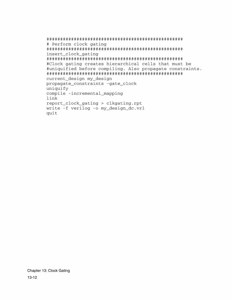
################################################### Perform clock gating##################################################insert_clock_gating###################################################Clock gating creates hierarchical cells that must be#uniquified before compiling. Also propagate constraints.##################################################current_design my_designpropagate_constraints -gate_clockuniquifycompile -incremental_mappinglinkreport_clock_gating > clkgating.rptwrite -f verilog -o my_design_dc.vrlquit
13-12
Chapter 13: Clock Gating

Index
Symbols!= (not-equal-to test) 6-33, 6-92#define 5-28#ifdef 5-29#include 5-29& (AND) 6-30, 6-32() (signal concatenation) 6-60= (assignment operator) 6-23>> (right shift) << (left shift) 6-35?: (conditional operator) 6-38^ (XOR) 6-30, 6-32, 9-37{} (substitution) 5-31| (OR) 6-30, 6-32, 9-37
AAbort button 4-17adders
addition 9-7aofcla 9-25Booth-encoded multipliers 9-9carry propagate 9-4carry-propagate 9-23, 9-29cla 9-26clsa 9-24, 9-26csa 9-24, 9-26fastcla 9-25, 9-26
fastclsa 9-26multiplication 9-8non-Booth-encoded multipliers 9-8optimized ripple 9-27recommended cells 7-18ripple 9-25, 9-27ripple_alt 9-25, 9-27sign extension 9-5subtraction 9-7using Wallace trees 3-20
additionadders 9-7architecture 9-4final 6-25functions based on 6-29operators 6-25sign extension 9-5
Allow Pseudo Cells in Opt option 4-20analysis
debugging 8-53design report information 8-40naming 8-12optimization 8-63output files 8-2pipelining 8-30running Design Compiler 8-49syntax and synthesis errors and warnings
8-55
IN-1

Verilog or VHDL simulation 8-34AND 6-30, 9-37AND-OR trees, library requirements 7-17ANDOR-based multiplexer architectures 6-39aofcla adders 9-25architecture
addition 9-4carry-propagate adders 9-24designer control 3-26
areamethods of computing 7-4overview 3-24units 3-24, 7-4
argument lists, variable 5-43arguments, module 5-7arithmetic computation 9-3 to 9-34assignment operator 6-23asynchronous set-reset flip-flops
async_clear 6-14async_preset 6-14definition 6-13
attributesaccessing with directive 5-25async_clear 6-14, 6-17, 6-18async_preset 6-14, 6-17, 6-18carrysave 6-27, 6-29, 6-89, 9-3, 9-30clock 6-44, 6-74dcopt 6-79, 8-52defined 5-25delay 6-75delstate 6-47, 10-24dirext 6-27, 6-28, 9-7enable (pipestall) 6-69, 6-74, 10-8, 10-12fadelay 6-27fatype 6-27, 6-28, 9-24fatype, list of 9-24group 6-69intround 6-27, 9-13logopt 6-78maxtreedepth 6-27, 9-22
multtype 6-27, 6-28muxtype 6-38outdelay 6-4outload 6-4pipeline 5-25, 6-76, 10-10pipestall (enable) 10-12querying value 5-26round 6-27, 6-28, 9-11scan 6-47scope 5-25selectop 6-34setting 5-27synthesis 6-26
attributes affecting addition operators, list of 6-26
Automatic input registering, enabling 4-22Automatic ouput registering, enabling 4-22
Bbehavioral model 8-35, 8-56behavioral verification 8-35benefits 1-5binary constants 5-23, 6-7bit range
accessing 5-12signed and unsigned 6-8
bit widthscalling 5-38converting 6-9
bitwise logical functions 9-37black box support 6-54Booth-encoded multipliers
adders 9-9formats 9-8
buffering, automatic 3-28Build menu 4-33Build Regular Trees synthesis menu option
4-14building pseudocell libraries 2-14
IN-2

Ccache
directories 2-22global cache 2-16local cache 2-16
CAE/CAD tools, Module Compiler 3-12carry-propagate adder optimization 9-23carry-propagate adders 9-29carry-save signals
arithmetic computation 9-29bit format 9-3carry-save accumulator example 9-34carry-save modes 9-30controlling generation 6-29converting 9-31csconvert function 9-32hints for using 8-61, 9-31inputs 9-3reducing 6-29
CBAarchitecture 3-24libraries
area computation 3-24defined 7-4
CBA and non-CBA libraries 7-4cell
naming 7-12naming limitation 11-17
cell sets, required and recommended 7-11cell summary, viewing 4-31cells
available in technology library 4-12equivalent 7-28inserting into design 6-63, 6-64libraries, recommended 7-14
adders 7-18multiplexers 7-16rotators 7-16shifters 7-16
libraries, requirements 7-13AND-OR trees 7-17
flip-flops 7-16inverters 7-15latches 7-17XOR trees 7-18
marked as don’t use 7-27pseudocells 7-27recommended
adders 7-18multiplexers 7-15, 7-16rotators 7-15, 7-16shifters 7-15, 7-16
requiredAND-OR trees 7-17flip-flops 7-16inverters 7-15latches 7-17XOR trees 7-18
required for combinational designs 7-13required for sequential designs 7-12synthesis cells 7-27untyped 7-27view mapping 4-33viewing
datasheets 4-32usage summary 4-31
checklist, first-run 2-12circuits
squaring 9-11steps in generating 3-15
cla adders 9-26CLK
default clock signal 3-29predefined global signal variable 5-24predefined operand 3-17
clock gatingflows 13-2for Power Compiler flow
-mc option 13-5sample script 13-11
in dc_shellsteps for running 13-3
in dc_shell-t
IN-3
sample script 13-7netlist, Power Compiler 13-8steps for running 13-9using the -cg option 13-9using the -db option 13-9
clock port limitation 11-16clock signals, declaring 6-70clocks
groups 6-76in groups 6-74multiple 6-74simple timing model 3-19supported by Module Compiler 3-29
clsa adders 9-24, 9-26command-line interface, overview 3-4command-line options in mc -h output 3-4command-line options, list of 3-5comments 5-4comparison operators 6-33comparison, equality 6-34Compile (Design Compiler menu) 4-24concatenation function 6-60concepts and constraints 3-1conditional blocks (if/else) 5-32 to 5-33constant arguments function 5-46constant multipliers 9-10constant shifts, missing data 3-32constants
binary 6-7decimal 6-7dont care 6-7hexadecimal 6-7octal 6-7types of 5-22
constants, description of 6-7constraint files 4-23constraints, external 3-31contextual information 4-29Continue on Warnings synthesis menu option
4-14
continuous time delay 3-19, 3-20critical path
analysis 6-82for each group 4-24viewing 4-30viewing user-defined 4-31
critical paths, user-defined 4-31, 8-43csa adders 9-24, 9-26customizing Module Compiler 2-10
Ddata format problems 8-62datapaths
building 3-14definition 1-2delay goal 3-26
datasheets, viewing 4-32DB Netlist, generating 4-27dc_shell
commands 11-3constraints
setting 11-7enabling 11-4libraries, link and target 11-4limitations 11-16Module Compiler design, reading 11-5overview 11-3reports, Module Compiler 11-9synthesizing Module Compiler design 11-8
dc_shell-tGUI mode limitation 11-17input registering limitation 11-16parameter iteration file limitation 11-17
debugging 8-53 to 8-63as part of design flow 3-13flattening input 8-53names in reports 4-28user-defined group reports 8-40
decimal constants 5-23, 6-7deferred declarations 5-49
IN-4
degenerate cases 3-32delay
attribute 6-75calculating 7-5constraints 3-26derating model 7-9goals
controlling 3-26group 3-17, 6-76multiple 6-76, 6-78optimization criterion 4-7
matching 3-21setting delay value using dp_opt 6-76timing model 7-5
delay equalizationsetting global 8-67using 8-67
demultiplexing 6-52derate_fast_named_opcond 2-9derate_slow_named_opcond 2-9derate_typ_named_opcond 2-9derating models 7-9design
cell or module 3-17description 5-5module definition 5-6network object, as 3-17viewing statistics 4-30viewing summary 4-31, 8-11
Design Compiler 4-23 to 4-25changes to instance names 4-24constraint and command files 8-50controlling 8-49disabling optimization 6-79enabling 4-23input options 8-52optimization submenu 4-22post-optimization 8-51RAMs 8-51registers, naming conventions 8-19reports and netlist 8-12
running 4-23 to 4-25viewing output netlist 4-32
Design Compiler optimization, submenu 4-22Design Compiler optimization, using dcopt
8-52Design Compiler shell
commands 11-3constraints
setting 11-7enabling 11-4example script 11-10libraries, link and target 11-4limitations 11-16Module Compiler design
reading 11-5setting constraints 11-6synthesizing 11-8
overview 11-3reports, Module Compiler 11-9
Design Compiler shell, using 11-1Design Compiler, running 4-23design constraints
bitwise constraints on ports 12-10checking reports 12-13commands 12-2dc_shell environment 12-5precedence order 12-9stand-alone environment 12-7units 12-4
design constraints, overview 12-2Design Report
generating 4-27viewing 4-31
design retimingbenefits of 10-3
design reuse 3-15design strategy
debugging the design 8-53 to 8-63designer control 3-25 to 3-32extreme outputs 8-62hierarchy 3-15
IN-5

logic optimization 8-63, 8-66poor utilization 8-62using functions 5-39using groups 6-68 to 6-78, 8-58
design, inserting cells into 6-64DesignWare floating-point adder 6-11DesignWare floating-point comparator 6-11DesignWare floating-point divider 6-11DesignWare floating-point multiplier 6-11DesignWare floating-point-to-integer converter
6-11DesignWare integer-to-floating-point converter
6-11deskewing 8-60directives (see attributes)discrete time delay 3-19Display Max Area, entering 4-38Display Max FF for synthesis status display
4-38Display Max Latency, entering 4-38Display Num Bars, entering 4-38Do All button 2-14, 4-6, 4-34don’t care constants 6-7don’t use cells 6-66dont_use property 2-28dp_dc_wireload 2-9dp_editor 4-11dp_tech_lib 2-9
EEDIF netlists
contents 8-11generating 4-28
Edit Input File 4-10editing keyboard shortcuts 4-39editor, changing 4-11endmodule keyword 5-7environment variables
controlling logic optimization using dp_logopt 8-66
list of 3-5mc.env files 2-9, 2-10querying value 2-27setting 11-6setting delay equalization using
dp_equalglob 8-67setting with mcenv utility 2-27technology-specific 2-9UNIX, list of 2-7using flip-flops with dp_asyncFF_active_high
6-15equality comparison 6-34Equalization Iterations
quick-set 4-17setting 4-19
error messages 5-56errors
logic 8-56messages 5-56overloaded net violations 8-61
example, creating a video processor 6-84exiting Module Compiler 4-13explicit port mapping 6-67
FFast Timing Iterations, quick-set 4-17fastcla adders 9-25, 9-26fastclsa adders 9-26fatal error message 5-56fatype attributes, list of 9-24feedback inputs 5-47File menu 4-9 to 4-13FIR filters 10-23, 10-24first-run checklist 2-12Flatten Pseudo Cells option 4-19, 4-21flattening input for debugging 8-53flip-flops
IN-6
active-high clear or preset 6-15conversion in scan mode 3-31hints for using 8-60library requirements 7-16recommended cells 7-16
flow control 5-30 to 5-39format conversion circuits 6-41formats, operand 3-25functions
AccPM 6-10accum 6-10addition 6-25addition-based 6-29alup 6-10as network objects 3-17bitrev 6-10bitwise logical 9-37buffer 6-10, 6-58, 6-59built-in 5-53calling conventions 5-51cat 5-54, 6-10, 6-60clkgrp 6-78concatenation 6-60constant arguments 5-46count 6-11crc 6-11critmode 6-82critpath 6-82declaring variables 5-51decode 6-11defining 5-5demux 6-11, 6-52disablepath 6-82DW_add_fp 6-11DW_cmp_fp 6-11DW_div_fp 6-11DW_flt2i_fp 6-11DW_i2flt_fp 6-11DW_mult_fp 6-11enablepath 6-82ensreg 6-11, 6-46eqreg 6-11, 6-46, 10-18
eqreg1 6-11, 6-46, 10-18eqreg2 6-11, 6-46, 10-18fa1a 6-62feedback inputs 5-47fir 6-11formatStr 5-53generic cell library 6-61input and output names 8-16isolate 6-12, 6-58join 6-12, 6-61library 5-54, 6-10local variables 5-51mac 6-12maccs 6-12mag 6-12, 6-29magnitude comparison 6-25max2 6-12maxmin 6-12mcgen_and2a 6-62min2 6-12missing data 3-32Module Compiler Express 4-12multp 6-12, 6-29norm 6-12norm1 6-12, 6-43overriding declarations 5-50passing in variables 5-49preg 6-12, 6-45, 6-74, 10-9ram2 6-74sat 5-54, 6-13, 6-42sati 6-13, 6-42sequential 6-45sgnmult 6-13, 6-29shiftlr 6-13showgroup 6-80, 8-40signal functions 5-54signal inputs 5-46signal outputs 5-48sreg 6-13, 6-45, 6-46, 6-74user-defined 5-42using VAR in argument list 5-45width 5-53
IN-7
GGen Reports button 4-26generating circuits 3-15generating reports 4-26 to 4-29, 6-83generic cell library, using 6-61generic cells 7-26global 2-16global cache 2-16Global Equalization option 4-19Global Iterations
quick-set 4-17setting 4-19
global keyword 5-24global pseudocell cache library 2-19global variables
CLK 5-24integer 5-24precedence 5-24strings 5-24
group names mode 8-29Group Report (Design Compiler menu) 4-24groups
clocks 6-74definition 3-17delay goals 3-26, 6-76disabling Design Compiler 6-79group analysis 6-80in complex designs 6-68 to 6-78misc 3-17names 4-14, 6-80, 8-29naming 6-69pipelining 6-76reporting critical path 4-24statistics 4-30timing 6-75user-defined reports 8-40viewing summary 4-31
GUI interface 4-3 to 4-38GUI objects 4-39input fields 4-4
log window 4-5overview 4-3status window 4-5
HHelp menu 4-39hexadecimal constants 5-22, 6-7hierarchy, as design strategy 3-15hints
carry-save problems 8-61data format problems 8-62extreme outputs 8-62logic errors 8-56pipelining 8-60poor utilization 8-62rectifying poor timing 8-57reducing runtime and memory use 8-63rule violations 8-61
II/O constraints 6-4I/O Summary, viewing 4-31Include Path synthesis option 4-15included files, path 4-15Incremental Mapping (Design Compiler menu)
4-24info function 4-29input files 4-6, 4-10 to 4-12, 5-3
comments 5-4editing 4-10finding 4-11function definition 5-5macros 5-4module definition 5-4path to included files 4-15retrieving parameters from 4-12
input flow control 5-30 to 5-38input operands, viewing 4-31input registering limitation 11-16
IN-8
input statement, module inputs 5-7inputs
bitwise functions 9-37converting 6-42delaying 10-19demultiplexing 6-52Design Compiler 4-24feedback 5-47general layout 5-3inversion 9-38module 5-7Module Compiler 3-11, 3-13, 3-14parameters 4-7sign extension 9-38substitution 5-31to functions 5-46
installationdefinition 2-4platform requirements 2-2testing 2-14
instancesdefinition 3-18names
changing during optimization 4-24naming conventions 4-14, 8-12
optimization 3-15integer expressions 6-8integer variables
integer expressions 6-8rules for 5-16 to 5-20
internal rounding 9-13inverters, library requirements 7-15
Kkeyboard shortcuts for editing 4-39keywords
error 5-56global 5-24info 5-55integer 5-24
string 5-21, 5-24warning 5-55wire 5-24
Llanguage parsers, setting options 4-14Language synthesis menu option 4-14latches
library requirements 7-17recommended cells 7-17
latencyautomatic pipelining 3-27controlling 3-21design issue 3-19deskewing 3-22, 8-60hiding 6-41, 8-60in sequential circuits 3-19minimizing 3-21
latency, resolving 10-13Library Browser 4-12library functionality 7-11library functions 5-54Library menu 4-35Library menu options 4-35 to 4-36library of functions 6-10Library Options dialog box 4-35library order limitation 2-13Library Report 4-33, 7-20 to 7-28
don’t use cells 7-27equivalent cells 7-28generic cells 7-26pseudocells 7-27sample 7-21synthesis cells 7-27untyped cells 7-27wire load models 7-26
licenses neededclock gating 13-2Module Compiler 2-2, 13-2
IN-9
licensing 2-2load isolation 6-58loading
constraints 6-4derating model 7-9
local cache 2-16Local Iterations
quick-set 4-17setting 4-19
log filecontents 8-4naming 4-37obtaining information, using
the -l option 8-4the -logmode option 8-4the -m option 8-4
log windowclearing 4-33contents 4-5setting height 4-38
logic errors 8-56logic optimization, controlling 8-66logic optimization, enabling/disabling 3-28,
6-78logical operators 6-30loops (replicate, repl) 5-34loops, pipelining in 3-22
Mmacro preprocessor 5-27 to 5-30
#define 5-28#ifdef 5-29#include 5-29
macros, defining 5-4makeMcLibCache 2-16, 2-20Map Effort (Design Compiler menu) 4-25mapping to technology-specific cells 7-26Max Input Load synthesis option 4-16Max Messages, entering 4-37
MCDIR variable 2-7mc.env file 2-8, 2-11
black box support 6-55constraint precedence 12-9created 2-24dc_shell, not used with 11-7dc_shell-t, limitation 11-17definition 2-6mcenv utility 2-26pseudocells 2-16register naming 8-20variables, shared 2-9, 2-10
mcenv utility 2-24, 2-25, 2-26, 2-27mcenv utility, using 11-6MCENVDIR variable 2-8MCLIBDIR variable 2-7memory usage, reducing 8-63messages
error 5-56fatal error 5-56functions for printing 5-54information 5-55limiting number 4-37types of 5-54warning 5-55with info function 4-29
missing data 3-32Module Compiler Express functions 4-12Module Compiler Language 5-3
#define 5-28#ifdef 5-29#include 5-29addition operators 6-25argument declaration 5-7assignment operator (=) 6-23async attributes 6-17async set-reset flip-flop support 6-13black box support 6-54buffer 6-59built-in and library functions 5-53carrysave 6-28, 6-29
IN-10

comparison operators 6-33components 5-3constants 6-7constants, types of 5-22creating a video processor 6-84critical path analysis 6-82critmode 6-82critpath 6-82, 6-83dcopt 6-79decoder function 6-41delay 6-44, 6-75delay goals 6-76delstate 6-47, 10-24demultiplexing 6-52demux 6-52Design Compiler 6-79direct sign extension 6-28directives and attributes 5-25dirext 6-28disablepath 6-82enablepath 6-82, 6-83ensreg 6-46eqreg, eqreg1, eqreg2 6-46, 10-18example, creating a video processor 6-84fatype 6-28final adder types 6-28flip-flops with active-high clear 6-15format conversion circuits 6-41function library 6-10functions based on addition 6-29general layout of input 5-3generic cell library 6-61group attribute 6-75group names 6-80groups, naming 6-69groups, using 6-68I/O constraints 6-4if/else 5-32input flow control 5-30inserting netlists into the design 6-63integer conversion (normalize) 6-42integer operators 5-16
integer variables 5-16, 6-8isolate 6-58join 6-61logic optimizer 6-78logical operators 6-30logical, reduction, shift, and MUX operators
6-30logopt 6-78loops (replicate, repl) 5-34macro preprocessor 5-27mag 6-29matching latency 10-18maxtreedepth 6-27mcgen_fa1a 6-62messages 5-54module definition 6-3module parameters 6-5modules 5-6, 5-7multiplexing 6-38multp 6-29multtype 6-28muxtype 6-38naming modules 6-3netlists 6-63norm and norm1 6-44operands 6-8operator precedence 5-12optimizing performance and area 6-85optimizing with Design Compiler 6-79overview 5-3pipeline 6-76, 10-10pipeline loaning 10-19pipelining 10-10preg 6-45, 6-74reduction operators 6-32report control 6-79report functions 6-80rotate 6-34round 6-28sat, sati (saturation functions) 6-42saturation function 6-41scan cells 6-47
IN-11

selectop 6-34sequential circuits 6-44sequential functions 6-45sgnmult 6-29shift 6-34showgroup 6-80signal concatenation 6-60signal manipulation functions 6-58signal operators 5-12signals connected to clear and preset 6-15sreg 6-45, 6-46, 6-74state registers 6-46string operators 5-20string variables 5-20substitution construct 5-31synthesis attributes 6-25technology-specific cells 6-63three-state drivers 6-61user-defined critical paths 6-82using 6-3 to 6-78using groups 6-68using multiple clocks 6-74variables 5-8
modulesbuilding, flow 3-9constraints 6-4declaring arguments 5-7defining 5-5, 5-7I/O constraints 6-4naming 6-3parameters, specifying 6-5reuse 3-15signal interface 6-4
More Options (Synthesis menu) 4-15MSB 6-8multiplexers
ANDOR-based 6-39decoders 6-41recommended cells 7-16specifying 6-40three-state-based 6-40using selectop 6-34
multiplexingusing the ?: conditional operator 6-38
multiplicationadders 9-8using Wallace trees 3-20
multipliersBooth-encoded 7-20, 9-8constant 9-10errors 9-16non-Booth-encoded 9-8recommended cells 7-20signed 9-10specifying with multtype 6-28
Nnamed opconds
derating models 7-9finding valid 7-26setting 4-36
namescontrolling 3-32, 8-17during optimization 4-24function input and outputs 8-16group 6-69instance 4-24, 8-12naming conventions
generating instance names in lowercase 8-14
generating net names in lowercase 8-15naming conventions, overview 8-12net 8-14registers 8-19, 8-32Use Group Names 4-14wire 8-15
NAND 9-38netlists
EDIF 8-11inserting into the design 6-63naming conventions 8-12
generating net names in lowercase 8-14recommended cells 7-17
IN-12

seeing available 4-12Verilog 8-8viewing 4-32
networkattributes
area 3-24overview 3-18summary 3-14timing 3-18
objects 3-14, 3-17postprocessing 8-49
newline, entering in string 5-21non-Booth-encoded multipliers, adders 9-8None, Min, Normal, or Full optimization values
4-18NOR 9-38Normal/Verbose 4-29normalization of inputs 6-42not-equal-to test 6-33, 6-92numeric representation 3-25
Oobsolete constructs 4-15octal constants 5-22, 6-7operands
concatenation 6-60conversion 6-42converting value range 6-41data format problems 8-62definition 3-17format 3-25, 6-8normalizing 6-42viewing summary 4-31
operating conditionsnamed opconds 7-9pseudocells 2-16setting 4-35viewing 4-32viewing model 4-36
operators
addition 6-25assignment 6-23comparison 6-33conditional operator 6-38definition 3-17logical 6-30precedence 5-11reduction 6-32rotate 6-34shift 6-34signal operators 5-11string 5-21
optimizationaborting 4-25area 6-85carry-propagate adders 9-23controlling 3-18criteria 3-29, 4-7delay attribute 6-75description 3-15Design Compiler 8-51Equalization Iterations 4-19Global Equalization 4-19Global Iterations 4-19groups 6-79iterations 4-19Local Iterations 4-19menu 4-17Optimize button 4-6overview 3-10performance 6-85quick-set options 4-17selecting steps 4-20session settings 4-9specifying criterion 4-7starting 4-34status display 4-25, 4-38steps
defined 8-64order of, automatic 8-64
Optimization menu 4-17 to 4-26optimization support, size only 6-66
IN-13

optimization valuesNone, Min, Normal, and Full 4-18
optimized ripple adders 9-27options menu 4-37options, setting 4-37options, setting Library menu 4-35 to 4-36OR 6-30, 9-37outload attribute 4-16output files 8-2 to 8-69
generating 8-2using the -b option 8-3using the -l option 8-3using the -r option 8-3using the -t option 8-3using the -v option 8-3
Output Load synthesis option 4-16output operands, viewing 4-31outputs
function 5-48generating reports 4-34module 5-7Module Compiler 3-11, 3-13, 8-2 to 8-69postprocessing 8-49summary of files 8-2synthesis 4-16
overview, Module Compiler 1-2 to 1-8
Pparameter iteration file 4-7parameter iteration file limitation 11-17parameters
module 4-7module, specifying 6-5parameter iteration file 4-7retrieving 4-12
parsers, setting options 4-14performance
hints for improving 8-53 to 8-69timing 3-19
Wallace trees 3-20pipeline
attribute 6-76loaning 10-19 to 10-24register-instance names 8-30registers 3-21, 6-44, 10-18slack 4-16synthesis option 4-14
Pipeline Slack synthesis option 4-16Pipeline synthesis menu option 4-14pipelining
automatic 3-22, 3-27, 10-10capabilities 10-2equalization functions 10-18flows 10-9functions
eqreg 10-18eqreg1 10-18eqreg2 10-18equalization 10-18
groups 6-76hints for using 8-60input latency 10-16input registering 10-4latency
input 10-16matching 10-18output 10-10
manual 6-45, 10-9matching latency 10-18output registering 10-4resolving latency
ResolveLatency 10-13ResolveLatencyLoop 10-13
slack for automatic 4-16user-specified output latency 10-10
platform requirements 2-2ports
mapping 6-67specifying 6-67
postprocessing networks 8-49
IN-14

Power Compiler, using Module Compiler netlist 13-8
power, optimization criterion 3-29precedence
global variables 5-24operators 5-12
properties file (dont_use cells) 2-28pseudocell cache library, global 2-19pseudocells
automated generation 2-18building libraries 2-14flattening 4-19, 4-21flow diagram 2-15generation 2-16global cache 2-16global pseudocell cache library 2-19local cache 2-16McLibCache flow 2-19optimization 4-20, 4-21prebuild 2-16viewing loaded cells 7-27
Qquerying variable values 2-27Quickstart 2-12quotes, entering in strings 5-21
RRAMs, in Design Compiler 8-51reduction operators 6-32registering, input and output 10-4registers
names 8-19pipeline 6-44shift 6-46state 6-44, 6-46
regularity of structures 4-14replicate and repl constructs 5-34, 8-54
Report Constraints command (Design Compiler) 4-24
reports 8-2 to 8-69controlling 6-79critical path analysis 6-82debugging names 4-28Design Compiler 8-12Design Report 4-27EDIF Netlist 4-28, 8-11Gen Reports button 4-6generating 4-26 to 4-29, 4-34group analysis 6-80log file 8-4Normal mode 4-29overview 3-10requesting more information 8-41summary 8-2table file 8-11user-defined critical paths 8-43user-defined group reports 8-40Verbose mode 4-29, 8-4Verilog Behavioral file 8-8Verilog Behavioral model 4-27Verilog Netlist 4-27, 8-8viewing reports 4-29 to 4-33
Reports menu 4-26 to 4-29required cell sets 7-11resistance models 7-10resolving latency 10-13results analysis 8-2 to 8-69
critical path analysis 6-82EDIF Netlist 8-11log file 8-4overview 3-10requesting group information 6-82simulation files 8-34table file 8-11Verilog Behavioral file 8-8Verilog Behavioral model 4-27Verilog Netlist 8-8
Retime, setting 4-22
IN-15
ripple adders 9-25, 9-27ripple_alt adders 9-25, 9-27rotators
recommended cells 7-16rotate operator 6-34using selectop 6-34
roundinginternal 9-13simple 9-11
running Design Compiler 4-23 to 4-25, 8-49runtime, reducing 4-24, 8-63
Sscalar setup times 7-7scan cells
final netlist 6-49limitations, style 6-50scan chain 6-51sequential designs, synthesizing 6-48support 6-48synthesizing sequential designs 6-48test 6-47user-instantiated 6-50
scan chain 6-51scan test mode
flip-flop conversion 3-31methodologies, Module Compiler support
3-31recommended cells 7-17scan attribute 6-47Scan Test Mode synthesis menu option 4-14
SDC (see Synopsys Design Constraints)semicolons in statements 5-7sequential circuits
clocks 3-29describing 6-44timing 3-19
sequential functions 6-45sequential models 7-11session file (.dps) 2-25
session settings 4-9sessions
defined 2-25loading and saving 4-9, 4-11
setting general options 4-37setting options 4-10setup times 7-7setup.csh 2-6, 2-11, 2-13shift operators 6-34shift registers 6-46shifters
recommended cell 7-16using selectop 6-34
showgroup function 8-40sign extension
direct 9-7Module Compiler algorithm 9-5using 6-28
signal concatenation 6-60signal connected to clear or preset 6-15signal expressions, integer variables 5-19signal functions 5-54signal inputs
declaring 5-7to functions 5-46
signal manipulation functions 6-58 to 6-61signal operators 5-11signal outputs
declaring 5-7from functions 5-48names 8-15
signal variables, rules for 5-11signals
accessing a bit range 5-12as operands 3-17carry-save 9-32data format problems 8-62names 8-15
signed multipliers 9-10signed numbers 3-25
IN-16

Sim Debug Mode 3-32, 4-28, 8-29, 8-36simulation
behavioral files 8-34Verilog gate-level netlist 8-36
size, optimization criterion 3-29skew, clocks 3-19squaring circuits 9-11stalling flip-flops 10-12standard load (unit) 7-4starting Module Compiler 3-3
using the command-line interface 3-4using the GUI 3-3using the -tech switch 2-13
state registers 3-21, 6-44, 6-46statements
semicolons in 5-7types of 5-7
statisticsviewing 4-30
Stats (View menu) 4-30status display 4-16
maximum flip-flops 4-38optimization 4-25setting area units 4-38setting maximum latency 4-38setting maximum number of bars 4-38synthesis 4-16
status window 4-5Steps, optimization 4-20Strict Parsing submenu, synthesis menu
options 4-15string keyword 5-21string variables, global 5-24strings
operators 5-21passing as arguments 5-21using 5-21variables 5-20 to 5-22
substitution construct 5-31subtraction, adders 9-7
Syn Behavioral Code (Design Compiler menu) 4-24
synlibcond 7-9Synopsys Common Licensing 2-2Synopsys Design Constraints (SDC)
commands 12-2constraint precedence 12-9defined 12-2format 12-2stand-alone environment 12-7units 12-4using the -sdc option 12-7with Module Compiler 12-5
Synopsys tools, other 1-7synthesis
aborting 4-17Build Regular Trees 4-14cells, in technology library 7-27controlling 3-18delay attribute 6-75description 3-15design description 5-5Include Path 4-15inputs 4-6interrupt on warning 4-14Max Input Load 4-16Module Compiler Express functions 4-12optimization criteria 4-6options 4-15Output Load 4-16overview 3-10pipeline option 4-14reporting status 8-4session settings 4-9setting options 4-14starting 4-34status display 4-16, 4-38Synthesize button 4-6
Synthesis menu 4-13 to 4-17synthesis options 4-14Synthesize button 4-6
IN-17

synthesized functions, buffering 3-28system administration 2-4, 2-10, 2-14
Ttab, entering in string 5-21table file 8-11Table Summary
clearing 4-33viewing 4-31
technology librarybuilding pseudocell libraries 2-14CBA 3-24CBA and non-CBA 7-4cell sets 7-11delay, capacitance, and area units 7-4derating load models 7-9don’t use cells 7-27equivalent cells 7-28functionality 7-3generic cell library 6-61generic cells 7-26loading 3-9location 2-6options 4-35pseudocells 7-27reports 7-20resistance models 7-10sequential models 7-11setup and hold time models 7-7specifying 2-13support 7-3 to 7-28Synopsys .db format 3-24synthesis cells 7-27timing models 7-5untyped cells 7-27using 7-1 to 7-28using the -tech option 2-13viewing available cells 4-12viewing information 4-33viewing options 4-35
wire load models 7-7, 7-26technology-specific environment variables 2-9temporary variables
definition 5-13testing installation 2-14testing, designer control 3-31three-state drivers 6-61three-state-based multiplexers 6-40time-scale setting
controlling 8-8values for controlling the precision unit 8-10values for controlling the reference unit 8-9
timingconstraints
I/O 6-4units 7-4
continuous time delay 3-20controlling latency 3-21debugging 8-57group delay goal 4-19groups, definition 3-17hints for improving 8-57logic optimization 3-28models 7-5optimization 8-68optimization criterion 3-29overview 3-19reports 8-50sequential circuits 3-19synthesis 3-20
Top Level Mode synthesis menu option 4-14
Uunits
delay 7-4load values 7-4loading constraints 7-4standard load 7-4technology library 7-4technology-independent 7-4
IN-18

timing constraints 7-4UNIX environment variables 2-7unsigned numbers, representing 3-25untyped cells 7-27usage summary of cell 4-31Use Group Names 3-32, 8-36Use Group Names synthesis menu option 4-14User Quickstart 2-12user quickstart 2-12user-defined critical paths, viewing 4-31using
command-line interface 3-4user quickstart 2-12
Vvariable argument lists 5-43variables
environment 2-7global 5-24integer variables 5-16 to 5-20, 6-8naming 5-8naming local 5-51passing into functions 5-49precedence 5-24rules for using 5-8signal variables 5-9, 5-11string variables 5-20 to 5-22
verbose mode 8-4Verilog Behavioral file 8-8Verilog Behavioral model
generating 4-27viewing 4-32
Verilog Netlist 8-8, 8-36generating 4-27viewing 4-32
VHDL supportbehavioral description 8-38configurations 8-40entity generation, disabling 8-39
functions, internally defined 8-40gate-level description 8-38standard libraries 8-36technology libraries 8-37
video processors, creating 6-84View menu 4-29 to 4-33viewing reports and output 4-29 to 4-33viewing reports and statistics 4-29 to 4-33
WWallace trees
algorithm 9-22generation 6-31multiplication 3-20reducing inputs 9-22, 9-38uses 3-20
warning messages 5-55warnings
interrupt synthesis for 4-14toggle display 4-15
width function 5-53wire keyword 5-24wire load models
finding valid 7-26Module Compiler support 7-7names 7-8pseudocells 2-16setting 4-35used in Module Compiler 3-19
wiresformat conversion 6-41global 5-24naming 8-12, 8-15resistance 7-10
XXOR 6-30, 9-37XOR trees, library requirements 7-18XOR trees, recommended cells 7-18
IN-19
Related Documents