2 Module-Based Synthesis of Digital Microfluidic Biochips with Droplet-Aware Operation Execution ELENA MAFTEI, PAUL POP, and JAN MADSEN, Technical University of Denmark Microfluidic biochips represent an alternative to conventional biochemical analyzers. A digital biochip ma- nipulates liquids not as continuous flow, but as discrete droplets on a two-dimensional array of electrodes. Several electrodes are dynamically grouped to form a virtual device, on which operations are executed by moving the droplets. So far, researchers have ignored the locations of droplets inside devices, considering that all the electrodes forming the device are occupied throughout the operation execution. In this article, we consider a droplet-aware execution of microfluidic operations, which means that we know the exact posi- tion of droplets inside the modules at each time-step. We propose a Tabu Search-based metaheuristic for the synthesis of digital biochips with droplet-aware operation execution. Experimental results show that our approach can significantly reduce the application completion time, allowing us to use smaller area biochips and thus reduce costs. Categories and Subject Descriptors: B.7.2 [Integrated Circuits]: Design Aids General Terms: Algorithms, Design, Performance Additional Key Words and Phrases: Biochips, microfluidics, synthesis ACM Reference Format: Maftei, E., Pop, P., and Madsen, J. 2013. Module-Based Synthesis of Digital Microfluidic Biochips with Droplet-Aware Operation Execution. ACM J. Emerg. Technol. Comput. Syst. 9, 1, Article 2 (February 2013), 21 pages. DOI:http://dx.doi.org/10.1145/2422094.2422096 1. INTRODUCTION According to Moore’s law [Moore 1965] the number of transistors on an integrated circuit doubles approximately every two years. “More than Moore” explores new appli- cations in which such systems can be used, focusing on function diversification rather than increasing density. An emerging field related to embedded systems is the design of efficient, low-cost devices for the biomedical area, which has been highlighted by the International Technology Roadmap for Semiconductors 2007 [ITRS07] as an important system driver for the near-future [Chakrabarty et al. 2010]. In recent years, microfluidic biochips (also called labs-on-chips) have emerged as a miniaturized alternative to conventional laboratories. On such devices, biochemical applications can be performed using small amounts of fluids, in the range of micro- or nanolitres. In addition to lower reagent costs compared to conventional laboratories, biochips can be fully automated and provide higher sensitivity. This article is an extended and revised version of the paper presented in Proceedings of the International Conference on Compilers, Architecture, and Synthesis for Embedded Systems (CASES’09), 195–203. Authors’ address: E. Maftei, P. Pop, and J. Madsen, Technical University of Denmark, 2800, Kgs. Lyngby, Denmark; email: [email protected]. Permission to make digital or hard copies of part or all of this work for personal or classroom use is granted without fee provided that copies are not made or distributed for profit or commercial advantage and that copies show this notice on the first page or initial screen of a display along with the full citation. Copyrights for components of this work owned by others than ACM must be honored. Abstracting with credit is per- mitted. To copy otherwise, to republish, to post on servers, to redistribute to lists, or to use any component of this work in other works requires prior specific permission and/or a fee. Permissions may be requested from Publications Dept., ACM, Inc., 2 Penn Plaza, Suite 701, New York, NY 10121-0701 USA, fax +1 (212) 869-0481, or [email protected]. c 2013 ACM 1550-4832/2013/02-ART2 $15.00 DOI:http://dx.doi.org/10.1145/2422094.2422096 ACM Journal on Emerging Technologies in Computing Systems, Vol. 9, No. 1, Article 2, Pub. date: February 2013.

Welcome message from author
This document is posted to help you gain knowledge. Please leave a comment to let me know what you think about it! Share it to your friends and learn new things together.
Transcript

2
Module-Based Synthesis of Digital Microfluidic Biochips withDroplet-Aware Operation Execution
ELENA MAFTEI, PAUL POP, and JAN MADSEN, Technical University of Denmark
Microfluidic biochips represent an alternative to conventional biochemical analyzers. A digital biochip ma-nipulates liquids not as continuous flow, but as discrete droplets on a two-dimensional array of electrodes.Several electrodes are dynamically grouped to form a virtual device, on which operations are executed bymoving the droplets. So far, researchers have ignored the locations of droplets inside devices, consideringthat all the electrodes forming the device are occupied throughout the operation execution. In this article,we consider a droplet-aware execution of microfluidic operations, which means that we know the exact posi-tion of droplets inside the modules at each time-step. We propose a Tabu Search-based metaheuristic for thesynthesis of digital biochips with droplet-aware operation execution. Experimental results show that ourapproach can significantly reduce the application completion time, allowing us to use smaller area biochipsand thus reduce costs.
Categories and Subject Descriptors: B.7.2 [Integrated Circuits]: Design Aids
General Terms: Algorithms, Design, Performance
Additional Key Words and Phrases: Biochips, microfluidics, synthesis
ACM Reference Format:Maftei, E., Pop, P., and Madsen, J. 2013. Module-Based Synthesis of Digital Microfluidic Biochips withDroplet-Aware Operation Execution. ACM J. Emerg. Technol. Comput. Syst. 9, 1, Article 2 (February 2013),21 pages.DOI:http://dx.doi.org/10.1145/2422094.2422096
1. INTRODUCTIONAccording to Moore’s law [Moore 1965] the number of transistors on an integratedcircuit doubles approximately every two years. “More than Moore” explores new appli-cations in which such systems can be used, focusing on function diversification ratherthan increasing density. An emerging field related to embedded systems is the designof efficient, low-cost devices for the biomedical area, which has been highlighted by theInternational Technology Roadmap for Semiconductors 2007 [ITRS07] as an importantsystem driver for the near-future [Chakrabarty et al. 2010].
In recent years, microfluidic biochips (also called labs-on-chips) have emerged as aminiaturized alternative to conventional laboratories. On such devices, biochemicalapplications can be performed using small amounts of fluids, in the range of micro- ornanolitres. In addition to lower reagent costs compared to conventional laboratories,biochips can be fully automated and provide higher sensitivity.
This article is an extended and revised version of the paper presented in Proceedings of the InternationalConference on Compilers, Architecture, and Synthesis for Embedded Systems (CASES’09), 195–203.Authors’ address: E. Maftei, P. Pop, and J. Madsen, Technical University of Denmark, 2800, Kgs. Lyngby,Denmark; email: [email protected] to make digital or hard copies of part or all of this work for personal or classroom use is grantedwithout fee provided that copies are not made or distributed for profit or commercial advantage and thatcopies show this notice on the first page or initial screen of a display along with the full citation. Copyrightsfor components of this work owned by others than ACM must be honored. Abstracting with credit is per-mitted. To copy otherwise, to republish, to post on servers, to redistribute to lists, or to use any componentof this work in other works requires prior specific permission and/or a fee. Permissions may be requestedfrom Publications Dept., ACM, Inc., 2 Penn Plaza, Suite 701, New York, NY 10121-0701 USA, fax +1 (212)869-0481, or [email protected]© 2013 ACM 1550-4832/2013/02-ART2 $15.00DOI:http://dx.doi.org/10.1145/2422094.2422096
ACM Journal on Emerging Technologies in Computing Systems, Vol. 9, No. 1, Article 2, Pub. date: February 2013.

2:2 E. Maftei et al.
Microfluidic biochips can be used in a wide range of fields such as clinical diagnosis,DNA analysis, protein assays and immuno-assays [Chakrabarty 2010]. Consideringthe potential of such devices for the biotechnology industry, the complexity of biochipsis expected to increase, with thousands of operations executed concurrently. In order tosupport the increase in complexity of these devices and therefore their market growth,computer aided design (CAD) tools are required, which can offer the same level of sup-port as the one taken for granted currently in the semiconductor industry. Initially,designers have used a bottom up approach for the design of biochips, combining fluidiccomponents to create specific-application devices [Fair 2007]. However, this bottom-upapproach does not scale to the new designs. Consequently, top-down design methodshave been proposed in Chakrabarty and Zeng [2007], increasing the level of abstrac-tion in biochip synthesis. Such techniques are necessary in order to improve the designof biochips, and to hide the implementation details of running biochemical assays fromthe users [Chakrabarty 2010].
This article focuses on the synthesis of digital microfluidic biochips (DMBs). Onthese devices, fluids are manipulated as discrete droplets on a two-dimensional ar-ray of identical cells, without the need of micro-structures, which offers flexibility andreconfigurability.
1.1. Related WorkOn a digital biochip, operations such as mixing and dilution are performed on the mi-crofluidic array by routing the corresponding droplets on a series of electrodes. Twoapproaches have been considered so far for operation execution. The module-basedapproach considers that a microfluidic operation is performed by routing the corre-sponding droplet on a group of adjacent electrodes, forming a virtual device. A differ-ent approach, called routing-based synthesis, has been proposed by us in Maftei et al.[2010a], where the concept of modules has been eliminated, allowing droplets to moveon any route during operation execution.
This article is based on the module-based synthesis approach. Researchers have ini-tially addressed architectural-level and physical-level synthesis of DMBs separately.In one of the first papers on this topic, an ILP and two heuristic techniques (a mod-ified List Scheduling algorithm and a Genetic Algorithm) have been proposed for thearchitectural-level synthesis of biochips [Su and Chakrabarty 2004]. The methods con-sider the problem of scheduling under resource constraints, by roughly estimating theplacement of devices on the microfluidic array. The results in Su and Chakrabarty[2004] have been improved in Ricketts et al. [2006], by using a hybrid Genetic Algo-rithm for scheduling operations under resource constraints.
Although it reduces the complexity of the synthesis problem, the separation of ar-chitectural and physical-level synthesis has disadvantages, leading in many cases to alonger completion time of the applications on the biochips [Maftei et al. 2008]. There-fore, the next step taken by researchers was considering a unified approach for thearchitectural-level synthesis and placement for digital microfluidic biochips.
The first unified methodology was proposed in Su and Chakrabarty [2005], by us-ing a combination of Simulated Annealing and Genetic Algorithms. The focus of thedeveloped method has been on deriving an implementation that can tolerate faultyelectrodes. Xu and Chakrabarty [2007] have extended the work done by Su andChakrabarty [2005], by incorporating routing-awareness during the architectural-level synthesis and placement of modules. The results obtained in Su and Chakrabarty[2005] have been improved in Yuh et al. [2007], by using a tree-based topological rep-resentation. The floorplanning algorithm has also been extended to take into accountthe reconfigurability of biochips in case of defective electrodes. In Maftei et al. [2009]we proposed a Tabu Search-based algorithm for the unified synthesis problem and we
ACM Journal on Emerging Technologies in Computing Systems, Vol. 9, No. 1, Article 2, Pub. date: February 2013.

Module-Based Synthesis of Digital Microfluidic Biochips 2:3
have shown in Maftei [2011] that our method obtains better results than the T-treeapproach presented in Yuh et al. [2007].
So far, researchers have assumed that during operation execution in module-basedsynthesis the droplet repeatedly follows the same pattern inside the virtual module,leading to an operation completion time determined through experiments. The actualposition of the droplet inside the virtual device has been ignored, by considering thatall the electrodes forming the device are occupied throughout the operation execution.In order to avoid the accidental merging of droplets it was considered that a device issurrounded by a 1-cell segregation area, containing cells that cannot be used until theoperation performing on the device is completed.
In this article, we consider a droplet-aware execution of microfluidic operations,which means that we know the exact position of droplets inside the modules at eachtime-step, and we can control them to avoid accidental merging, if necessary.
1.2. ContributionIn this article, we propose a synthesis approach based on a Tabu Search metaheuristic,which, starting from a biochemical application modeled as a sequencing graph and agiven biochip array, determines the allocation, resource binding, and scheduling of theoperations in the application at the same time as module placement.
Our scheduling and placement steps consider the positions of droplets inside virtualdevices during their execution. This allows us to better utilize the chip area, since nosegregation cells are needed to separate the modules, and improve the routing step,since the routes can now cross over modules, if needed. Another advantage of droplet-aware operation execution, is that it allows the partial overlapping of modules, whichcan increase parallelism. However, in this article we do not consider module overlap-ping, which is left for future work. We show that our droplet-aware operation execu-tion approach can significantly reduce the application completion time compared tothe black-box approach.
The article is organized in six sections. Section 2.1 presents the architecture of a dig-ital microfluidic biochip. We introduce the abstract model used to capture a biochemi-cal application in Section 2.2. We formulate the problem in Section 3 and illustrate thedesign tasks using several examples. The proposed approach is presented in Section 4and evaluated in Section 5. Section 6 presents our conclusions.
2. SYSTEM MODEL2.1. Biochip ArchitectureThe architecture of a digital biochip is dependent on the actuation mechanism used forcreating and manipulating the droplets. The most-used methods are dielectrophore-sis (DEP) and electrowetting-on-dielectric (EWOD) [Tabeling 2006]. Both methods arebased on electrical forces and can provide high transportation speeds for droplets, us-ing simple biochip architectures [Chakrabarty and Zeng 2007]. In this article we con-sider digital microfluidic biochips based on the EWOD actuation method.
The schematic of a general EWOD architecture is presented in Figure 1(a). Thechip is composed of a microfluidic array of identical cells, together with reservoirsfor storing the liquid. Each cell is composed of two parallel glass plates, as shownin Figure 1(b). The top plate contains a single indium tin oxide (ITO) ground electrode,while the bottom plate has several ITO control electrodes. The electrodes are insu-lated from the droplet through an insulation layer of ParyleneC, on which a thin filmof Teflon-AF is added [Srinivasan et al. 2004]. The role of the Teflon layer is to providea hydrophobic surface on which the droplet will move. The two parallel plates are sep-arated through a spacer, providing a fixed gap height. The droplet moves between thetwo plates, in a filler fluid (e.g., silicone oil), used in order to prevent evaporation and
ACM Journal on Emerging Technologies in Computing Systems, Vol. 9, No. 1, Article 2, Pub. date: February 2013.

2:4 E. Maftei et al.
Fig. 1. Biochip architecture.
Fig. 2. Microfluidic modules.
the adhesion of molecules on the surface of the chip [Chakrabarty et al. 2010]. Besidesthe microfluidic array, the chip also contains nonreconfigurable devices, such as detec-tors and reservoirs, whose locations are fixed after the fabrication of the biochip. Thenumber of nonreconfigurable devices to be integrated on the chip is decided during thedesign phase.
With EWOD, the droplet is transported on the chip by applying voltages on the con-trol electrodes, thus modifying the contact angle between the liquid and the hydropho-bic surface. If the voltage is applied to only one side of the droplet, the gradient in thecontact angle at the two edges of the liquid will cause a surface stress in the directionof the applied voltage, leading to the movement of the droplet [Pollack et al. 2002a].For example, turning off the middle control electrode and turning on the right controlelectrode in Figure 1(b) will force the droplet to move to the right.
Using the architecture in Figure 1(a), and changing the control voltages, the basicmicrofluidic operations, such as transport, splitting, dispensing, mixing, and detection,can be performed. For example, two mixing operations on 1 × 4 modules (Mixer1 andMixer2)1 are shown in Figure 2(a). Mixing is done by transporting two droplets tothe same location and merging them. Mixing through diffusion, where the resultingdroplet remains on the same electrode, is very slow. In order to enhance the mixingprocess, the droplet is routed over a series of electrodes according to a certain pattern.During movement, the complexity of flow patterns inside the droplet increases, leading
1In the figures we denote Mixeri with Mi and Diluteri with Di.
ACM Journal on Emerging Technologies in Computing Systems, Vol. 9, No. 1, Article 2, Pub. date: February 2013.

Module-Based Synthesis of Digital Microfluidic Biochips 2:5
to faster operation execution [Paik et al. 2003]. Mixing modules are created by group-ing adjacent electrodes on which the droplets corresponding to the operations will bemoved. Any cells in the chip can be used for such a purpose, thus we say that the chipis reconfigurable.
Table I presents the results of the experiments performed in Paik et al. [2003], whereseveral mixing times were obtained for various areas, creating a module library. Foreach experiment, the corresponding droplet has been repeatedly moved inside the vir-tual module, using a predefined movement pattern. The synthesis tools for biochipsproposed so far use such a module library, ignoring the location of the droplet duringoperation execution and thus considering a module as a black box in which an opera-tion is performed.
However, the position of all droplets on the chip at each time-step is importantin order to avoid droplet-merging. If two droplets are next to each other on twoadjacent cells, they will tend to merge and form one single droplet. For furtherdetails on these fluidic constraints see Section 3. Segregation cells have been usedfor solving this problem, while ignoring the position of droplets in virtual devices[Su and Chakrabarty 2005; Yuh et al. 2007]. Thus, each device has been surroundedby a 1-cell segregation border to isolate functional areas on which operations areexecuting (see Figure 2(a)). This results in two segregation cells between modules,although a single cell is enough. The two-cell space has the advantage that is easierto adjust to create droplet routing paths. If the positions of droplets inside devicesare not known, routing needs a three-cell path width. So far it has been consideredthat these paths are created during a post-processing routing step. For example, inFigure 2(b) the position of Mixer2 is modified in order to introduce necessary path fordroplet movement between the two mixer modules.
However, segregation cells can be eliminated if we take into account the posi-tion of droplets inside modules during execution. Let us consider the two mixers inFigure 2(a). Each mixer is composed of a 1 × 4 functional area, surrounded by segrega-tion cells to avoid accidental merging. We eliminate the segregation area and considerthat the corresponding cells become part of the virtual device (e.g., Mixer1 transformsfrom a 1 × 4 to a 3 × 6 device). We can prevent the accidental merging of the droplets byknowing their locations inside the devices at any time-step. For example, consideringthe initial positions of the two droplets as shown in Figure 2(c), the mixing operationscan be performed by repeatedly routing the droplets according to the movement pat-terns described by the arrows. The droplets are never too close to each other duringexecution, so the fluidic constraints are enforced. Such a synchronization of droplets toavoid accidental merging is not always possible.
However, since we know the positions of the droplets we can decide to stop a dropletor change its movement pattern inside a module, to enforce fluidic constraints.
Knowing the locations of droplets inside modules can also be an advantage dur-ing the post-synthesis routing step. Let us consider that during the routing step adroplet d must be routed from the cell denoted by c1 to the cell denoted by c2 (seeFigure 2(b)). The post-synthesis routing algorithms proposed so far have considereddevices placed on the chip as obstacles in defining the routes between two modulesor between modules and reservoirs, and that the initial placement has to be adjustedin order to introduce the three-cell-width paths necessary for routing, as shown inFigure 2(b). However, droplets can be routed through the functional area of a module,as long as accidental merging is avoided. Let us assume that at time t, the dropletsinside the mixers are positioned as shown in Figure 2(c) and are moved according tothe pattern shown by the arrows in the mixers. Then droplet d can be routed fromthe start cell c1 to the destination cell c2 on the shortest possible route (shown by thearrow between c1 and c2), using electrodes belonging to Mixer1, as long as we ensure
ACM Journal on Emerging Technologies in Computing Systems, Vol. 9, No. 1, Article 2, Pub. date: February 2013.

2:6 E. Maftei et al.
Table I. Module Library
Operation Area (cells) Time (s)Mixing/Dilution 2 × 4 2.9Mixing/Dilution 1 × 4 4.6Mixing/Dilution 2 × 3 6.1Mixing/Dilution 2 × 2 9.9
Dispensing – 2
Fig. 3. Application graph.
the fluidic constraints. For example, in order to avoid accidental merging inside Mixer1we can stop the mixer droplet for four time-steps on its current position (we mark thestopping place by an “X” on the corresponding electrode). This will allow the routeddroplet d to be transported on its optimal path to the electrode denoted by c2. Due tothe fact that the droplets in Mixer1 and Mixer2 are no longer synchronized, we cannotcontinue moving the droplet in Mixer2 according to its original movement pattern, asthis would result in an accidental merging with the stopped mixing droplet in Mixer1.Thus, in order to enforce fluidic constraints, we can deviate the movement pattern forthe droplet in Mixer2, as shown with dashed arrows in Figure 2(c).
Changing this movement will result in an irregular pattern, and lead to nonstandardoperation completion times (i.e., we cannot use the numbers in Table I, which assume acertain fixed movement pattern). Hence, we instead use the execution time calculationmethod proposed by us in Maftei et al. [2010a] to compute the completion time of anoperation on a droplet-aware device.
The analytical method in Maftei et al. [2010a] takes into account the exact move-ment pattern of a droplet inside a device to give a safe conservative estimate of theoperation completion time. We use the routing approach presented in Maftei et al.[2010a] to decide the initial locations of droplets inside modules.
2.2. Biochemical Application ModelWe model a biochemical application using an abstract model consisting of a sequencinggraph [Chakrabarty and Zeng 2005]. The graph G(V , E) is directed, acyclic, and polar(i.e., there is a source node, which is a node that has no predecessors and a sink nodethat has no successors). Each node Oi ∈ V represents one operation. The binding ofoperations to modules in the architecture is captured by the function B : V → A, whereA is the list of allocated modules from the given library L.
An edge ei,j ∈ E from Oi to Oj indicates that the output of operation Oi is the inputof Oj. An operation can be activated after all its inputs have arrived and it issues itsoutputs when it terminates. We assume that for each operation Oi, we know the execu-tion time CMk
i on module Mk = B(Oi), where it is assigned for execution. In Figure 3 we
ACM Journal on Emerging Technologies in Computing Systems, Vol. 9, No. 1, Article 2, Pub. date: February 2013.

Module-Based Synthesis of Digital Microfluidic Biochips 2:7
have an example of an application graph with thirteen operations, O1 to O13. The ap-plication consists of two mixing operations (O6 and O7), three diluting operations (O5,O12 and O13), and eight input operations (O1, O2, O3, O4, O8, O9, O10 and O11). O5is a diluting operation during which the concentration of the sample input droplet ischanged to an intermediate concentration. The operation is performed by a sequence ofmixing and splitting steps. Considering Figure 1(b), a droplet is split by turning on theleft and right electrodes and turning off the middle electrode [Ren et al. 2003]. Thus,the droplet volume will vary during the application execution. We assume that thebiochemical application has been correctly designed, such that all the operations willhave the required input droplet volumes. Let us consider that operation O5 is boundto a 2 × 2 diluter module denoted by Diluter2 (i.e., B(O5) = Diluter2). Then, accordingto Table I, the execution time for O5 will be CDiluter2
5 = 9.9 s. The execution2 of an op-eration is divided in time-steps of 10 ms, and we capture the set of time-steps with T .
3. PROBLEM FORMULATIONThe problem we are addressing in this article can be formulated as follows.
Input.
(1) A biochemical application modeled as a graph G(V , E);(2) a biochip consisting of a two-dimensional m × n array C of cells;(3) a characterized module library L;(4) the maximum number of nonreconfigurable devices of each type that can be inte-
grated on the chip.
Output.
(1) Allocation A, which determines what modules from the library L should be used;(2) the binding B of each operation Oi ∈ V to a module Mk ∈ A;(3) the schedule S of the operations, which contains the start time tstart
i and finish
time tfinishi of each operation Oi on its corresponding module, Mk;
(4) the placement P containing for each Mk ∈ A, the bottom left corner(
xlk, yl
k
)and
the upper right corner(xr
k, yrk)
describing the position of the module on the m × n
array, i.e., P(Mk) =(
xlk, yl
k, xrk, yr
k
);
(5) the route R taken during the execution of an operation Oi, described by a set ofpoints
(xt
i, yti), ∀t ∈
[tstarti , tfinish
i
], ∀Oi ∈ G.
Objective. minimize the schedule length δG , i.e., minimize the finishing time tfinishsink of
the sink node of graph G.
Subject to the following.
(1) Precedence (a) and storage (b) constraints.(a) A successor operation can only start executing after the completion of its pre-
decessor: tfinishi ≤ tstart
j ∀Oi and ∀Oj ∈ V , such that ∃ei,j ∈ E .(b) If a successor operation is not scheduled immediately after the com-
pletion of its predecessor, a storage unit must be placed on the chip:
2Approximate time required to route the droplet one cell considering the data in Pollack et al. [2002a]:electrode pitch size = 1.5 mm, gap spacing = 0.3 mm, average linear velocity = 20 cm/s.
ACM Journal on Emerging Technologies in Computing Systems, Vol. 9, No. 1, Article 2, Pub. date: February 2013.

2:8 E. Maftei et al.
store(Oi, tcurrent) ∀tcurrent ∈ T and ∀Oi and ∀Oj ∈ V such that ∃ei,j ∈E and tfinish
i ≤ tcurrent < tstartj .
(2) Nonreconfigurable resource constraints.No operations bound to the same nonreconfigurable device should overlap in time:tfinishi ≤ tstart
j ∀Oi and ∀Oj nonreconfigurable operations ∈ V such that B(Oi) =B(Oj) = Mk.
(3) Placement constraints.No modules placed on the microfluidic array at time t should physically overlap:xl
i ≤ xrj or xl
j ≤ xri or yl
i ≤ yrj or yl
j ≤ yri ∀Oi and ∀Oj ∈ V such that P(B(Oi)) =
(xli, yl
i, xri , yr
i ) and P(B(Oj)) = (xlj, yl
j, xrj , yr
j ) and tstarti ≤ tstart
j ≤ tfinishi .
(4) Fluidic constraints during operation execution.(a) The location of any two droplets present on the array at time t cannot
be directly or diagonally adjacent to each other:∣∣∣xt
i – xtj
∣∣∣ ≥ 2 or∣∣∣xt
i – ytj
∣∣∣ ≥2 ∀Oi and ∀Oj ∈ V , such that R(Oi, t) = (xt
i, yti) and R(Oj, t) = (xt
j, xtj) ∀t ∈ T .
(b) The activated cell for a droplet cannot be adjacent to any other droplet presenton the array:
∣∣∣xt+1i – xt
j
∣∣∣ ≥ 2 or∣∣∣yt+1
i – ytj
∣∣∣ ≥ 2 or∣∣∣xt
i – xt+1j
∣∣∣ ≥ 2 or∣∣∣yt
i – yt+1j
∣∣∣ ≥2 ∀Oi and ∀Oj ∈ V , such that R(Oi, t) = (xt
i, yti) and R(Oj, t) = (xt
j, ytj) ∀t ∈ T .
The next sections will illustrate each of the output tasks. The presentation orderdoes not correspond to the order in which our synthesis approach performs these tasks.
3.1. Allocation and PlacementLet us consider the graph shown in Figure 3. We would like to implement the opera-tions on the 8 × 8 biochip from Figure 1(a). The graph contains two types of operations:nonreconfigurable (input) and reconfigurable (mixing and dilution). The scheduling ofinput operations is determined at the same time as the other operations, the fixednumber of reservoirs representing a constraint to the final completion time of the ap-plication. However, inputs execute outside the microfluidic array and therefore do notaffect the placement of the other operations. We assume that the locations of reservoirshave been decided during the fabrication of the chip and are as shown in Figure 1(a).We need to assign each input operation to a reservoir of the same type, e.g., O2 canonly be assigned to one of the buffer reservoirs, B1 and B2. Let us consider that theinput operations are assigned to the input ports as follows: O1 to the input port S1, O2to B1, O3 to S2, O4 to R1, O8 to S3, O9 to B1, O10 to R2, and O11 to B2. The synthesisapproach will have to decide the scheduling of the input operations and make sure thateach reservoir is used by at most one input operation at each time-step. For the recon-figurable operations in Figure 3, the mixing operations (O6 and O7) and the dilutionoperations (O5, O12 and O13), our synthesis approach will have to allocate the appro-priate modules, bind operations to them, and perform the placement and scheduling.
Let us assume that the available module library is the one captured by Table I. Wehave to select modules from the library while trying to minimize the application com-pletion time and place them on the 8 × 8 chip. We ignore the position of droplets insidemodules, and we wrap the modules in segregation cells, as explained in Section 2.1.
One solution to the problem is presented in Figure 4, where the following modulesare used: one 2 × 4 mixer (4 × 6 with segregation area), one 2 × 4 diluter (4 × 6 withsegregation area), one 1 × 4 mixer (3 × 6 with segregation area), and two 2 × 3 diluters(4 × 5 with segregation area). The resulting schedule for this allocation is shown inFigure 4(a). The schedule is depicted as a Gantt chart, where for each module, we
ACM Journal on Emerging Technologies in Computing Systems, Vol. 9, No. 1, Article 2, Pub. date: February 2013.

Module-Based Synthesis of Digital Microfluidic Biochips 2:9
Fig. 4. Black-box operation execution example.
represent the operations as rectangles with their length corresponding to the durationof that operation on the module.
The placement for the allocation and schedule is as indicated in Figures 4(b)–(c). Ourplacement problem has similarities with the placement of DR-FPGAs, where virtualmodules can physically overlap on-chip as long as they do not overlap in time, i.e., theyare used during different time intervals. After an operation has finished executing ona module, we can reuse the same cells as part of another module.
The placement problem of DMBs can also include finding the location of nonreconfig-urable devices (e.g., reservoirs, optical detectors), whose number is constrained by thedesign specifications. As input operations are executed outside the microfluidic array,the positions of reservoirs are determined manually, after the placement of the otherdevices. The locations of optical detectors on the array are decided during the place-ment step of the synthesis process and remain fixed throughout the execution of theapplication. If the synthesis process decides the mapping of a biochemical applicationto an already fabricated biochip, then the locations of nonreconfigurable devices aregiven as part of the input specifications.
3.2. Binding and SchedulingOnce the modules have been allocated and placed on the cell array, we have to decideon which modules to execute the operations (binding) and in which order (scheduling),such that the application completion time is minimized.
Considering the graph in Figure 3 and the allocation presented in Section 3.1,Figure 4(a) presents the optimal schedule in the case when we do not consider theposition of droplets inside the virtual modules. For example, operation O7 is boundto module Mixer2, starts immediately after the diluting operation O5
(tstart7 = 4.9
)and
takes 4.6 s, finishing at time tfinish7 = 9.5 s. We consider that input operations are sched-
uled for execution as follows: tstart1 = tstart
2 = tstart3 = tstart
4 = 0 s, tstart8 = tstart
9 = tstart10 =
tstart11 = 2.9 s. Each dispensing operation takes 2 s, as shown in Table I. For space rea-
sons, we do not show the schedule of input operations, however the starting times ofthe reconfigurable operations shown in Figure 4(a) do take into consideration the timerequired for dispensing the droplets on the microfluidic array.
Note that special “store” modules have to be allocated if a droplet has to wait beforebeing processed, which is different from DR-FPGAs. In general, if there exists an edgeei,j from Oi to Oj such that Oj is not immediately scheduled after Oi (i.e., there is adelay between the finishing time of Oi and the start time of Oj), then we will have to
ACM Journal on Emerging Technologies in Computing Systems, Vol. 9, No. 1, Article 2, Pub. date: February 2013.

2:10 E. Maftei et al.
Fig. 5. Droplet-aware operation execution example.
allocate a storage cell for ei,j. Hence, the allocation of storage cells depends on how theschedule is constructed. Any available cell on the microfluidic array can be used fortemporarily storing the droplet.
3.3. Synthesis with Droplet-Aware Operation ExecutionThe schedule presented in Figure 4(a) is optimal for the given allocation consideringthat the positions of droplets inside modules are unknown during operation execution.Therefore, modules are surrounded by segregation cells, which ensure that the fluidicconstraints are satisfied at each time-step. However, the solution can be further im-proved (see Figure 5(a)) by taking into account the location of droplets inside virtualmodules. Consider the same synthesis example as in Section 3.1, with the allocationpresented in Figure 4(a). At time t = 2, operations O5 and O6 are scheduled, andmodules Diluter1 and Mixer1 are placed on the chip. Let us assume that the dropletscorresponding to the two operations are routed to the positions shown in Figure 5(b),where the dilution and mixing operations start executing, according to the illustratedmovement patterns.
We eliminate the segregation cells, and consider them as part of the functional areaof the devices. For example, operation O5, which was initially bound to a 2 × 4 devicecan now be executed by routing the corresponding droplet on a 4 × 6 area. The areaoccupied for performing O5 remains the same as in Section 3.1, however all the cells inthe device can now be used for operation execution. By routing the droplets correspond-ing to O5 and O6 as shown in Figure 5(b), the droplets are never too close and thereforethe fluidic constraints are enforced. The same situation is shown in Figure 5(c), whereoperations O7, O12, and O13 are repeatedly routed from their initial positions accord-ing to the depicted movement patterns, without the need of segregation cells.
The completion times for the droplet-aware operations shown in Figure 5 are com-puted using the analytical method proposed by us in Maftei et al. [2010a]. Althoughfor simplicity reasons, the movement patterns of the droplets in Figure 5 are synchro-nized, this is not always possible due to fluidic constraints. Our approach takes thisinto consideration by allowing a flexible movement pattern of the droplets during op-eration execution. In order to avoid accidental merging, a droplet can be deviated fromits preestablished movement pattern according to the characterized module library, orcan be kept at the same location on the chip for several time-steps.
The exact routes taken by droplets inside a module during operation execution aredetermined offline and are stored in the memory of a microcontroller, which coordi-nates the activation of the electrodes on the microfluidic array. In order to minimize
ACM Journal on Emerging Technologies in Computing Systems, Vol. 9, No. 1, Article 2, Pub. date: February 2013.

Module-Based Synthesis of Digital Microfluidic Biochips 2:11
Fig. 6. Synthesis algorithm for DMBs.
memory requirements we consider that only the preestablished routes and the devi-ations of the droplets from these routes will be recorded in memory, in a compressedform.
4. TABU SEARCH-BASED SYNTHESISThe problem presented in the previous section is NP-complete. Scheduling in even sim-pler contexts is NP-complete [Ullman 1975]. In addition, the placement is equivalentto a sequence of 2D packing problems, known to be NP-complete [Garey and Johnson1979].
Our synthesis strategy, presented in Figure 6, takes as input the application graphG(V , E), the given biochip cell array C, and the module library L, and produces thatimplementation Ψ = < A, B, S, P , R > consisting of, respectively, the allocation A,binding B, scheduling S, placement P , and routing R of operations during execution,which minimizes the schedule length δG on the given biochip C. In this article, we usea Tabu Search (TS) metaheuristic to decide the allocation A and binding B (line 3 inFigure 6). For a given allocation and binding decided by TS, we use a List Scheduling(LS) heuristic [Micheli 1994] to decide the schedule S of the operations. As the resultof the synthesis process depends on the order of executing the operations, we use pri-orities Π to decide the scheduling sequence for two or more operations that are readyto be executed at the same time t.
4.1. List SchedulingFor given allocation, binding and priorities decided by TS, we use the ScheduleAnd-Place function in Figure 7 to determine the scheduling S, placement P , and routingR of droplets inside modules, during operation execution. Our scheduling is based ona List Scheduling heuristic. LS takes as input the application graph G(V , E), the cellarray C, the module library L, the allocation A, binding B, and priorities Π, and re-turns the scheduling S, placement P , and the routes of droplets inside modules R. TheList Scheduling heuristic is based on a sorted priority list, Lready, containing the op-erations Oi ∈ V , which are ready to be scheduled. TS starts from an initial solution,where we consider that each operation Oi ∈ V is bound to a randomly chosen moduleB(Oi) ∈ L (line 1 in Figure 6). The initial execution priorities, Π◦, are given accordingto the bottom-level values of the nodes in the graph (line 2) [Sinnen 2007]. Accordingto this, the priority of an operation is defined as the length of the longest path fromthe operation to the sink node of the graph. The start and finish times of all the oper-ations are initialized to 0 in the beginning of the algorithm (lines 2 and 3 in Figure 7).A list Lexecute, which contains the operations that are executing at the current timestep is created in the beginning of the algorithm (line 4). Initially, Lready will containthose operations in the graph that do not have any predecessors (line 5 in Figure 7).We do not consider input operations as part of the ready list. As they do not have anyprecedence constraints, input operations can be executed at any moment. However, itis important that inputs and their successors are performed sequentially, in order toavoid storing the dispensed droplets. Let us consider moment tcurrent during the ex-ecution of the application. For all the operations that finish executing at tcurrent we
ACM Journal on Emerging Technologies in Computing Systems, Vol. 9, No. 1, Article 2, Pub. date: February 2013.

2:12 E. Maftei et al.
Fig. 7. List scheduling algorithm for DMBs.
check if their successors are ready to be scheduled (line 14 in Figure 7). An operationis considered to be ready if all its predecessors (except input operations) have finishedexecuting. Next, we try and schedule the ready operations, starting with operation Ojhaving the highest priority (line 17 in Figure 7). Before Oj can be scheduled, its inputconstraints must be checked. If Oj has as predecessor an input operation Ok, we try toschedule Ok such that tfinish
k = tstartj = tcurrent. However, as reservoirs/dispensing ports
are nonreconfigurable devices, their number is constrained during design specifica-tions. That is, operation Oj can be scheduled at time t only if at time t – Creservoir
k thereis an available reservoir/dispensing port on which Ok can be executed. Otherwise, Ojwill be delayed and the next highest priority operation is considered for execution. Ifall the constraints related to Oj are satisfied, its corresponding module, B(Oj), is placedon the microfluidic array (line 18 in Figure 7) and the start time of the operation is up-dated (line 21). If there exists a placed storage module associated with the operationOj, the storage is removed and the placement is updated.
The combined scheduling, placement, and routing during operation execution is im-plemented by the ScheduleAndPlace function (Figure 7). Once an operation is sched-uled it is removed from Lready and added to Lexecute. Before the end of the iteration,the storage constraints are considered. For all the operations that finished at tcurrent,the placement of the microfluidic array must be updated by removing the modules to
ACM Journal on Emerging Technologies in Computing Systems, Vol. 9, No. 1, Article 2, Pub. date: February 2013.

Module-Based Synthesis of Digital Microfluidic Biochips 2:13
Fig. 8. Placement algorithm for DMBs.
which they are bound (line 11 in Figure 7). Also, if their successors have not yet beenscheduled for execution, a storage unit is placed on the microfluidic array. TS usesdesign transformations to search the solution space. Inside TS, we use the Schedule-AndPlace function to determine the schedule, placement and routing of droplets duringoperation execution for an implementation Ψ.
The next section presents our proposed placement algorithm, while Sections 4.3 and4.4 present our droplet-aware operation execution algorithm and TS implementation,respectively. Section 4.5 discusses the time complexity of the proposed TS algorithm.
4.2. Placement AlgorithmThe placement for DMBs can be considered as a 2D rectangle packing problem, inwhich at each time-step, the position of modules to be accommodated on the microflu-idic array must be decided. Our placement approach, presented in Figure 8, is basedon the “keep all maximal empty rectangles” (KAMER) algorithm proposed in Bazarganet al. [2000] for DR-FPGAs. The algorithm partitions the free space on the chip intoa list of overlapping rectangles, represented by the coordinates of their left bottomand right upper corners. When an operation is scheduled, the Placement algorithm inFigure 8 selects an empty rectangle that best fits the module to which the operationis bound. If there is no empty rectangle that can accommodate the device, the corre-sponding operation will be delayed until more space is freed on the microfluidic array.
Consider the synthesis example in Figure 5(c). At t = 4.17 s there are three opera-tions that are ready to be scheduled, hence Lready = {O7, O12, O13}. We consider thatthe reconfigurable operations are bound to the same devices as in Section 3.3, thus O7is bound to a 3 × 6 mixer, O12, and O13 to 4 × 5 diluters. Then the priorities of theoperations ready to be scheduled are computed based on the optimal routes on whichthe operations can be executed inside the modules: πO7
= CMixer2O7
= 2.5, πO12= CDiluter3
O12
= 2.25, πO13= CDiluter4
O13= 2.25.
Accordingly, the LS algorithm will select O7 and will call Placement to place Mixer2on the biochip array. At time t = 4.17 s, mixing operation O5 and dilution operation O6have finished executing, therefore the microfluidic array forms one big empty rectangleRect1 = (0, 0, 8, 8). The mixer bound to O7 is placed at the bottom corner of Rect1(line 6 in Figure 8). Consequently, in line 7, the free space will be updated to Lrect ={Rect1 = (3, 0, 8, 8), Rect2 = (0, 6, 8, 8)}, as depicted in Figure 9(a).
After the scheduling and placement of O7, the next operation to be considered forscheduling is O12. As rectangle Rect1 = (3, 0, 8, 8) is the only one sufficiently large toaccommodate the 4 × 5 module (line 4), Diluter2 will be placed at its bottom cornerand the free space will be updated to Lrect = {Rect1 = (3, 4, 8, 8), Rect2 = (0, 6, 8, 8)}, see
ACM Journal on Emerging Technologies in Computing Systems, Vol. 9, No. 1, Article 2, Pub. date: February 2013.

2:14 E. Maftei et al.
Fig. 9. Placement example.
Figure 9(b). Finally, Rect1 will be chosen for accommodating the diluter bound to O13and the final placement at t = 4.17 will be as shown in Figure 9(c).
In this case, the free space on the microfluidic array permits scheduling O7, O12,and O13 at time t. If however, there is not enough space to place the module bound toa ready operation, the scheduling of the operation will have to be delayed.
4.2.1. Placement of Nonreconfigurable Devices. The placement of a nonreconfigurable de-vice (e.g., an optical detector) on the microfluidic array is similar to that of a re-configurable module. However, once decided, the location of the device remains fixedthroughout the execution of the application. Therefore our algorithm maintains a listof locations at which nonreconfigurable operations of each type (e.g., detection opera-tions) can be performed, LnonReconf . These locations are established during the execu-tion of the placement algorithm. The size of the list is constrained by the maximumnumber of devices of the given type that can be integrated on the chip, given as aninput during design specifications. Let us consider that at time t a nonreconfigurabledetection operation is ready to be scheduled. We try to place the 3 × 3 detector at oneof the locations in Ldetect. If no locations have been established previously or if they areall occupied but we can still integrate detectors on the array, we use the algorithm inFigure 8 to find a new detector location. If a free rectangle that can accommodate the3 × 3 module is found, the operation is scheduled at time t and the point correspondingto the left bottom corner of the rectangle is added to Ldetect. Otherwise the detectionoperation cannot be scheduled at time t. Just as in the case of reconfigurable modules,nonreconfigurable devices cannot overlap with other modules placed on the chip.
4.3. Droplet-Aware Operation ExecutionThe movement of droplets during operation execution is determined offline by suc-cessively calling the RunOperationsOneTimeStep algorithm presented in Figure 10.The algorithm takes as input the list of operations executing at tcurrent, Lexecute, them × n matrix C of cells, the current placement of modules P , the partial routes R ofdroplets inside devices up to time tcurrent, the module library L, and the current time-step tcurrent. For each operation Oi under execution at tcurrent, the algorithm decidesthe movement of the corresponding droplet inside the module Mk = B(Oi) to which theoperation is bound, for the next time-step. Compared to previous approaches, we con-sider that the movement pattern followed by a droplet during operation execution canbe dynamically changed, in order to ensure fluidic constraints, and at the same timeminimize the completion time of the operation.
The analytical method proposed in Maftei et al. [2010a] is used for characterizingthe execution of operations, using as a starting point a given module library. According
ACM Journal on Emerging Technologies in Computing Systems, Vol. 9, No. 1, Article 2, Pub. date: February 2013.

Module-Based Synthesis of Digital Microfluidic Biochips 2:15
Fig. 10. Droplet-aware operation execution algorithm for DMBs.
to this method, any route can be decomposed into a sequence of forward, backward,and perpendicular moves. In order to determine the completion time of an operationfollowing an irregular movement pattern, we need to approximate the percentage ofexecution performed over one cell, corresponding to each type of move. The methodproposed in Maftei et al. [2010a] provides safe estimates of completion percentages,by decomposing the modules in the given module library that have preestablishedmovement patterns and known completion times, determined through experiments. Asa result, the method can be used to approximate the amount of operation completionfor any given droplet, during operation execution.
Let us consider the example in Figure 11(a), at time tcurrent. There are three op-erations executing on the array: O7, bound to a 3 × 6 mixer module and O12 andO13, bound to 4 × 5 diluters. Let us consider that the previous three moves for theoperations are as indicated in Figure 11(b), by the position of the droplets, and the cor-responding connecting arrows. We use a greedy approach for deciding the directionsin which the droplets are moved at the current time-step. For each droplet we have anumber of feasible moves that can be performed, while avoiding accidental merging.We consider that the quality of each move is given by the amount of operation comple-tion performed while transporting the droplet in the corresponding direction. We usethe analytical method proposed by us in Maftei et al. [2010a] to evaluate the qualityof each move (lines 2–4 in Figure 10). Consequently, according to our greedy approach,the droplet is transported in the best direction (line 6) and the percentage of opera-tion completion is updated (line 7), using the method proposed in Maftei et al. [2010a].If the operation finished executing (its completion percentage reached 100%) then itsfinishing time is also updated (lines 8–10).
Let us consider that the first droplet to be moved in Figure 11 is the one correspond-ing to mixing operation O7. The droplet can be moved downwards, backwards, or it canremain at the current position, see Figure 11(c). Based on the droplet characterizationin Maftei et al. [2010a], the droplet is routed downwards, as this leads to the mostmixing out of the feasible moves. After O7 is routed, the next droplet to be moved isO12. The droplet cannot continue its movement upwards, as it risks accidentally merg-ing with O7 (see Figure 11(d)). Hence, as shown in Figure 11(e), O12 is transported tothe right compared to its current position, which is the best possible move. Finally, thealgorithm chooses to keep O13 on the current position, as moving it backwards leads tonegative mixing [Maftei et al. 2010a] and moving it downwards breaks the fluidic con-straints (accidental merging with O7). Figure 11(f) shows the positions of the dropletsat time tcurrent + 1, after the moves have been performed.
ACM Journal on Emerging Technologies in Computing Systems, Vol. 9, No. 1, Article 2, Pub. date: February 2013.

2:16 E. Maftei et al.
Fig. 11. Running operations O7, O12, and O13 for one time-step.
4.4. Tabu SearchTabu Search (TS) [Glover and Laguna 1997] is a metaheuristic method used for solvingoptimization problems, by incorporating memory structures during the search process.This method has already been used successfully for a wide range of optimization prob-lems, such as scheduling, research planning, and VLSI design [Glover and Laguna1997]. Tabu Search is based on a neighboring technique, using design transformations(moves) applied to the current solution, Ψcurrent, to generate a set of neighboring solu-tions, N, that can be further explored by the algorithm.
In order to efficiently explore the search space and to escape local optimality, themetaheuristic uses a memory structure that records the recently visited solutions(a tabu list). The information related to the last performed moves is used to guideTabu Search through the search space, by restricting the possibility of reversing a pre-viously visited solution. However, labeling a move as tabu can result in prohibitingattractive solutions that have not been visited so far. In order to prevent this situa-tion, an “aspiration criteria” can be used, which allows a tabu solution to be visited,if it improves on the currently best known one. Moreover, two other strategies called“diversification” and “intensification” can be integrated in the Tabu Search in order toimprove the search process. During diversification, the metaheuristic is encouraged toexplore previously unvisited regions of the search space, and thus incorporate new el-ements that were not previously included in the solution. The intensification strategyfocuses on the extensive exploration of promising regions of the search space that havealready been visited, looking to improve the best found solution.
Our Tabu Search-based algorithm for droplet-aware module-based synthesis is pre-sented in Figure 12. In order to explore the search space the algorithm uses two typesof moves: (1) rebinding moves; and (2) priority swapping moves. During a rebinding
ACM Journal on Emerging Technologies in Computing Systems, Vol. 9, No. 1, Article 2, Pub. date: February 2013.

Module-Based Synthesis of Digital Microfluidic Biochips 2:17
Fig. 12. Tabu Search algorithm for DMBs.
move an operation Oi ∈ G is randomly selected and its binding is changed to a dif-ferent device in the module library. A priority swapping move consists in swappingthe priorities of two randomly chosen operations in the graph. We have used priorityswapping as part of a diversification strategy, when the best found solution does notimprove for a number of iterations, numdiv, determined experimentally.
We have considered that for each type of move, our algorithm maintains a tabu list,consisting of the recently performed transformations. In order to reduce the amount ofmemory required to memorize the search history, we do not record the entire solutions,but only the attributes that have changed as part of a transformation. For example, ifoperation Oi is rebound to module Mj as part of a rebinding move, the transformationwill be recorded in the corresponding tabu list as a pair of the form (Oi, Mj). The algo-rithm starts with an initial solution Ψ◦, where each operation is bound to a randomlychosen module and has a priority given according to the bottom-level value of the nodecorresponding to the operation. In order to evaluate the quality of the solution, theScheduleAndPlace function is used, which returns the schedule S◦ and placement P◦
for the given allocation and binding (line 1).Two empty tabu lists, tabuListdev and tabuListprio, used to record the rebinding
moves and the priority swapping moves, respectively, are initialized in lines 4–5.Each list has a given size, tabuSizedev and tabuSizeprio correspondingly, specifying
ACM Journal on Emerging Technologies in Computing Systems, Vol. 9, No. 1, Article 2, Pub. date: February 2013.

2:18 E. Maftei et al.
the maximum number of moves that can be recorded. In order to implement thediversification strategy, we use a variable numiter, which keeps track of the number ofiterations passed without the improvement of the best solution, Ψbest
G (line 6). Whilethe time limit set for running the algorithm has not been reached, we try to improvethe best found solution, by using a number of iterations (lines 7–29). During eachiteration, we perform rebinding moves to the current solution, and construct a setof neighboring solutions, N (line 8). However, N might contain solutions that aredisallowed by TS. For example, according to the aspiration criteria, if a move labeledas tabu is performed, the resulting solution is allowed only if it improves on the cur-rently best known solution. Therefore, all the tabu moves that are leading to a worsecompletion time than the best one, are removed from N and the set N of allowed movesis created (line 9). These moves are evaluated using the ScheduleAndPlace function,and the one leading to the best schedule is selected and marked as tabu (lines 10–12).If the obtained solution has a better schedule length that the currently known one, thebest-so-far solution is updated (lines 14–15). However, if the best known solution doesnot improve for a given number of iterations numdiv, our algorithm introduces diversi-fication into the search by performing a priority swapping move (line 18). If as a resultof diversification the best move is improved, then Ψbest is updated to Ψcurrent (line 23).After diversification is performed, the variable numiter is reset to 0 (line 26).
The Tabu Search-based algorithm in Figure 12 is given a time limit, during which itrepeatedly performs moves trying to find the best solution in the search space. Whenthe time limit is reached the best found solution in terms of schedule length, Ψbest, isreturned by the algorithm, which then terminates.
4.5. Time Complexity AnalysisLet us consider the overall algorithm presented in Figure 6. The time complexity isgiven by the Tabu Search algorithm in line 3, which uses the ScheduleAndPlace algo-rithm presented in Figure 7 to perform the scheduling, placement, and droplet-awareoperation execution for all the operations Oi in V . In order to implement the place-ment algorithm in Figure 8 we use the area matrix data structure proposed in Handaand Vemuri [2004]. According to this, the microfluidic array is modeled as a two di-mensional array m × n, in which each cell represents an electrode and stores a value.The value can be either positive, giving the number of contiguous empty cells abovethe cell, in the same column, or negative, if the cell is occupied by a module. Thedata structure leads to an efficient management of the free space using overlappingrectangles, requiring O(mn) for inserting a new module and the same for deleting amodule from the microfluidic array. As the placement is performed for all the readyoperations (line 18 in Figure 7), it has complexity O(|V|mn). If we consider the whileloop at line 7 in Figure 7, it contains two loops, the first one executing for operationsthat are finishing at the current time-step and having complexity O(|V|mn) and thesecond one, for placing ready operations, also requiring O(|V|mn). In order to performthe execution of operations, the ScheduleAndPlace uses the algorithm in Figure 10,which decides for each droplet on the array, which of the maximum five movementsis the best one to be performed. To ensure the fluidic constraints and therefore definethe valid moves for a droplet, the locations of all other droplets present on the chipmust be considered (line 3 in Figure 10). As a result, the RunOperationsOneTimeStepalgorithm has a complexity of O(|V|2). Considering that the number of elements in theneighborhood equals the number of operations in V , the overall complexity of the TabuSearch algorithm is O(
∣∣∣V3∣∣∣mn).
ACM Journal on Emerging Technologies in Computing Systems, Vol. 9, No. 1, Article 2, Pub. date: February 2013.

Module-Based Synthesis of Digital Microfluidic Biochips 2:19
Table II. Best-, Average Schedule Length, and Standard Deviation for the Real-Life Applications
Application Area (cells × cells) Best (s) Average (s) Standard dev. (%)DAS MBS DAS MBS DAS MBS
8 × 9 69.83 70.40 72.41 75.72 1.86 3.01In-vitro 8 × 8 71.69 82.43 83.67 91.31 11.73 9.63
7 × 8 74.13 86.82 82.93 95.73 8.01 8.6915 × 15 96.60 102.20 99.66 112.22 1.07 4.63
Proteins 14 × 14 95.63 107.12 99.68 116.78 1.12 5.3413 × 13 98.76 117.25 101.00 128.75 0.65 6.46
5. EXPERIMENTAL EVALUATIONIn order to evaluate our droplet-aware operation execution approach, we have usedtwo real-life applications and three synthetic TGFF-generated benchmarks. The TabuSearch algorithm was implemented in Java (JDK 1.6), running on an Intel Core i7 860at 2.8 GHz with 8 GB of RAM. The droplet movement characterization of operation ex-ecution is based on the decomposition of devices shown in Table I, using the analyticalmethod proposed in Maftei et al. [2010a].
In our experiments we were interested to determine the improvement in completiontime that can be obtained by eliminating segregation cells and considering the positionof droplets inside devices. Therefore we consider two approaches to the synthesis prob-lem: a droplet-aware operation execution approach (Droplet-Aware Synthesis, DAS)and a black-box operation execution approach (Module-Based Synthesis, MBS). ForMBS, we have used the synthesis method we proposed in Maftei et al. [2010b].
In order to determine the initial positions of droplets inside modules during droplet-aware operation execution, we have used the GRASP method developed by us in Mafteiet al. [2010a].
Table II presents the results obtained by using DAS and MBS for the synthesis oftwo real-life applications: in-vitro diagnostics on human physiological fluids [Su et al.2006], which has 28 operations, and the colorimetric protein assay (103 operations)[Su and Chakrabarty 2005]. Column 3 in the table represents the best solution outof 50 runs (in terms of the application completion time δG) for the droplet-aware ap-proach, and the black-box approach. The average and standard deviation over the 50runs compared to the best application completion time are also reported in Table II.The comparison is made for three progressively smaller areas. In Maftei et al. [2010b]we have shown that the quality of solutions produced by the MBS implementation doesnot degrade significantly if we reduce the time limit from 60 minutes to 10 minutes.Hence, we have decided to use a time limit of 10 minutes for all the experiments in thisarticle. A fast exploration is important since we envision using DAS for architectureexploration, where several biochip architectures have to be quickly evaluated in theearly design phase (considering not only different areas, but also different placementof nonreconfigurable resources).
As we can see, controlling the movement of droplets inside devices can lead to im-provements in terms of application completion time. For example, in the most con-strained case for the colorimetric protein assay (the 13 × 13 array in Table II), wehave obtained an improvement of 15.76% in the best schedule length and 21.55% inthe average schedule length. Note that the comparison between DAS and MBS is un-fair towards DAS. In DAS, the completion times presented in the table include routingtimes (moving the droplets between the devices). There are no routing times in theresults reported for MBS, where we consider that routing is done as a postsynthesisstep, which will introduce additional delays.
ACM Journal on Emerging Technologies in Computing Systems, Vol. 9, No. 1, Article 2, Pub. date: February 2013.
2:20 E. Maftei et al.
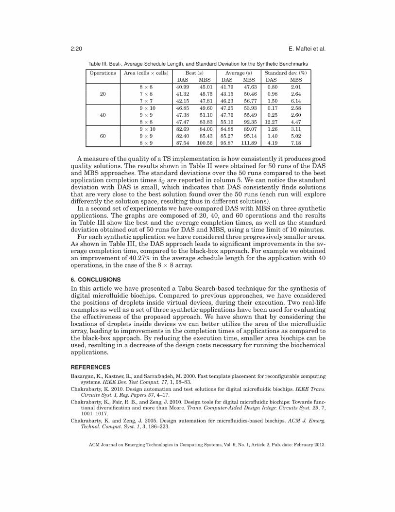
Table III. Best-, Average Schedule Length, and Standard Deviation for the Synthetic Benchmarks
Operations Area (cells × cells) Best (s) Average (s) Standard dev. (%)DAS MBS DAS MBS DAS MBS
8 × 8 40.99 45.01 41.79 47.63 0.80 2.0120 7 × 8 41.32 45.75 43.15 50.46 0.98 2.64
7 × 7 42.15 47.81 46.23 56.77 1.50 6.149 × 10 46.85 49.60 47.25 53.93 0.17 2.58
40 9 × 9 47.38 51.10 47.76 55.49 0.25 2.608 × 8 47.47 83.83 55.16 92.35 12.27 4.479 × 10 82.69 84.00 84.88 89.07 1.26 3.11
60 9 × 9 82.40 85.43 85.27 95.14 1.40 5.028 × 9 87.54 100.56 95.87 111.89 4.19 7.18
A measure of the quality of a TS implementation is how consistently it produces goodquality solutions. The results shown in Table II were obtained for 50 runs of the DASand MBS approaches. The standard deviations over the 50 runs compared to the bestapplication completion times δG are reported in column 5. We can notice the standarddeviation with DAS is small, which indicates that DAS consistently finds solutionsthat are very close to the best solution found over the 50 runs (each run will exploredifferently the solution space, resulting thus in different solutions).
In a second set of experiments we have compared DAS with MBS on three syntheticapplications. The graphs are composed of 20, 40, and 60 operations and the resultsin Table III show the best and the average completion times, as well as the standarddeviation obtained out of 50 runs for DAS and MBS, using a time limit of 10 minutes.
For each synthetic application we have considered three progressively smaller areas.As shown in Table III, the DAS approach leads to significant improvements in the av-erage completion time, compared to the black-box approach. For example we obtainedan improvement of 40.27% in the average schedule length for the application with 40operations, in the case of the 8 × 8 array.
6. CONCLUSIONSIn this article we have presented a Tabu Search-based technique for the synthesis ofdigital microfluidic biochips. Compared to previous approaches, we have consideredthe positions of droplets inside virtual devices, during their execution. Two real-lifeexamples as well as a set of three synthetic applications have been used for evaluatingthe effectiveness of the proposed approach. We have shown that by considering thelocations of droplets inside devices we can better utilize the area of the microfluidicarray, leading to improvements in the completion times of applications as compared tothe black-box approach. By reducing the execution time, smaller area biochips can beused, resulting in a decrease of the design costs necessary for running the biochemicalapplications.
REFERENCESBazargan, K., Kastner, R., and Sarrafzadeh, M. 2000. Fast template placement for reconfigurable computing
systems. IEEE Des. Test Comput. 17, 1, 68–83.Chakrabarty, K. 2010. Design automation and test solutions for digital microfluidic biochips. IEEE Trans.
Circuits Syst. I, Reg. Papers 57, 4–17.Chakrabarty, K., Fair, R. B., and Zeng, J. 2010. Design tools for digital microfluidic biochips: Towards func-
tional diversification and more than Moore. Trans. Computer-Aided Design Integr. Circuits Syst. 29, 7,1001–1017.
Chakrabarty, K. and Zeng, J. 2005. Design automation for microfluidics-based biochips. ACM J. Emerg.Technol. Comput. Syst. 1, 3, 186–223.
ACM Journal on Emerging Technologies in Computing Systems, Vol. 9, No. 1, Article 2, Pub. date: February 2013.

Module-Based Synthesis of Digital Microfluidic Biochips 2:21
Chakrabarty, K. and Zeng, J. 2007. Digital Microfluidic Biochips: Synthesis, Testing, and ReconfigurationTechniques. CRC Press.
Fair, R. B. 2007. Digital microfluidics: Is a true lab-on-a-chip possible? Microfluidics Nanofluidics 3, 3, 245–281.
Garey, M. R. and Johnson, D. S. 1979. Computers and Intractability—A Guide to the Theory of NP-Completeness. Freeman, New York.
Glover, F. and Laguna, M. 1997. Tabu Search. Kluwer Academic Publishers.Handa, M. and Vemuri, R. 2004. An efficient algorithm for finding empty space for online FPGA placement.
In Proceedings of the Design Automation Conference. 960–965.ITRS07. International Technology Roadmap for Semiconductors.
http://www.itrs.net/Links/2007ITRS/Home2007.htm.Maftei, E. 2011. Synthesis of digital microfluidic biochips with reconfigurable operation execution. Ph.D.
thesis, Technical University of Denmark.Maftei, E., Paul , P., and Madsen, J. 2009. Tabu search-based synthesis of dynamically reconfigurable dig-
ital microfluidic biochips. In Proceedings of the Compilers, Architecture, and Synthesis for EmbeddedSystems Conference. 195–203.
Maftei, E., Paul, P., and Madsen, J. 2010a. Routing-based synthesis of digital microfluidic biochips. In Pro-ceedings of the Compilers, Architecture, and Synthesis for Embedded Systems Conference. 41–49.
Maftei, E., Paul, P., and Madsen, J. 2010b. Tabu search-based synthesis of digital microfluidic biochips withdynamically reconfigurable non-rectangular devices. J. Des. Autom. Emb. Syst. 14, 287–308.
Maftei, E., Paul, P., Madsen, J., and Stidsen, T. 2008. Placement-aware architectural synthesis of digitalmicrofluidic biochips using ILP. In Proceedings of the International Conference on Very Large ScaleIntegration of System on Chip. 425–430.
Micheli, G. D. 1994. Synthesis and Optimization of Digital Circuits. McGraw-Hill Science.Moore, G. E. 1965. Cramming more components onto integrated circuits. Electronics 38, 8, 114–117.Paik, P., Pamula, V. K., and Fair, R. B. 2003. Rapid droplet mixers for digital microfluidic biochips. Lab Chip
3, 253–259.Pollack, M. G., Shenderov, A. D., and Fair, R. B. 2002a. Electrowetting-based actuation of droplets for inte-
grated microfluidics. Lab Chip 2, 96–101.Ren, H., Sriniasan, V., and Fair, R. B. 2003. Design and testing of an interpolating mixing architecture for
electrowetting-based droplet-on-chip chemical dilution. In Proceedings of the International Conferenceon Transducers, Solid-State Sensors, Actuators and Microsystems. 619–622.
Ricketts, A., Irick, K., Vijaykrishnan, N., and Irwin, M. 2006. Priority scheduling in digital microfluidics-based biochips. In Proceedings of Design, Automation and Test in Europe. Vol. 1. 1–6.
Sinnen, O. 2007. Task Scheduling for Parallel Systems. Wiley.Srinivasan, V., Pamula, V. K., and Fair, R. B. 2004. Droplet-based microfluidic lab-on-a-chip for glucose
detection. Analytica Chimica Acta 507, 145–150.Su, F. and Chakrabarty, K. 2004. Architectural-level synthesis of digital microfluidics-based biochips. In
Proceedings of the International Conference on Computer Aided Design. 223–228.Su, F. and Chakrabarty, K. 2005. Unified high-level synthesis and module placement for defect-tolerant
microfluidic biochips. In Proceedings of the 42nd Annual Conference on Design Automation. 825–830.Su, F., Hwang, W., and Chakrabarty, K. 2006. Droplet routing in the synthesis of digital microfluidic biochips.
In Proceedings of Design, Automation and Test in Europe. Vol. 1. 73–78.Tabeling, P. 2006. Introduction to Microfluidics. Oxford University Press.Ullman, D. 1975. NP-complete scheduling problems. J. Comput. Syst. Sci. 10, 384–393.Xu, T. and Chakrabarty, K. 2007. Integrated droplet routing and defect tolerance in the synthesis of digital
microfluidic biochips. In Proceedings of the Design Automation Conference. 948–953.Yuh, P.-H., Yang, C.-L., and Chang, Y.-W. 2007. Placement of defect-tolerant digital microfluidic biochips
using the T-tree formulation. ACM J. Emerg. Technol. Comput. Syst. 3, 3.
Received October 2010; revised April 2011, August 2011; accepted November 2011
ACM Journal on Emerging Technologies in Computing Systems, Vol. 9, No. 1, Article 2, Pub. date: February 2013.
Related Documents