1 Raju Poulose Kuwait Airways Module 5 Module 5 DIGITAL TECHNIQUES ELECTRONIC INSTRUMENT SYSTEMS

Welcome message from author
This document is posted to help you gain knowledge. Please leave a comment to let me know what you think about it! Share it to your friends and learn new things together.
Transcript
1
Raju Poulose Kuwait Airways Module 5
Module 5 DIGITAL TECHNIQUES
ELECTRONIC INSTRUMENT SYSTEMS

2
Raju Poulose Kuwait Airways Module 5
Electronic Instrument Systems
1. Typical displays on an EHSI are
* VOR, Map, Plan and weather radar
VOR, Plan, Map and Attitude
Engine indications
2. EADI displays show
pitch, roll and waypoints
* pitch and roll attitudes
heading and weather radar
3. ILS indications on PFD/ND are shown in
green
* magenta
cyan
4. The two sets of flight regulations that a pilot may fly by are
* VFR and IFR
VHF and IFR
VFR and IFU
5. An EADI display showing a moving runway moves down during the final stages of an approach. The aircraft must
fly up
* fly down
hold descent path
6. What are the basic elements for 'Classic T' format?
Airspeed, pitch and roll
Direction, altitude and height
* Airspeed, attitude, altitude and direction
7. An EADI display of flight director commands are coloured
* magenta
red
cyan
At 200ft, during Approach, the Rising Runway starts to move up the EADI display until, at touch down, it touches the bottom of the aircraft symbol. If the Rising Runway start to move down again it means that the aircraft is climbing and should FLY DOWN

3
Raju Poulose Kuwait Airways Module 5
8. An EFIS system ADI displays pitch, roll
* autoland, rad alt, decision height and slip indicator
autoland, altitude, compass rose and flight director bars
autoland, decision height, range to altitude and flight director bars and slip indicator
9. On an EFIS system the weather radar is displayed on
the EADI
* the EHSI
the FMC CDU
10. An EFIS ADI display will show along with pitch and roll
flight director bars, autoland, altitude, range to altitude, decision height
flight director bars, autoland, compass rose, altitude
* decision height, autoland, rad alt , altitude
11. An electronic flight instrument display consists of;
* Mode control panel, Raster and Stroke generator display, microprocessor and Data inputs
ADC, Altimeter, VSI and ASI
ADI, HSI and Symbol generator
12. EFIS systems have two control panels, their purpose is
to provide display control by one control panel whilst the other provides a standby
* one to control the type of EFIS display and the other to select the source of the information being displayed
one for the EADI display and one for the EHSI display
13. A modern Electronic Horizontal Situation Indicator will display the following:
* Waypoints, ILS Steering Information, Distance to go and Magnetic Heading
ILS Steering Information, Flight director information and Glide Slope Deviation
Ground speed, Magnetic Heading, Way points and Localiser
14. What is the fixed feature of an ADI?
The lateral deviation bar
* The aircraft symbol
The glideslope pointer
15. What functions are available on the EHSI?
* Full arc, Wx and Map Mode
Full arc and Wx only

4
Raju Poulose Kuwait Airways Module 5
Full Arc only
16. On an EADI, the Flight Director command bars show
* the required path with respect to the actual path
the actual path with respect to the required path
the path with respect to the horizon
17. During an instrument approach, the glideslope pointer deflects below the glideslope centre mark. This means the aircraft is positioned
below the glideslope
* above the glideslope
to the left of the localiser
18. What does ECAM mean?
Engine Centralised Aircraft Management System
* Electronic Centralised Aircraft Monitoring System
Engine Centralised Aircraft Monitoring System
19. What does EICAS mean?
Electronic indicator and crew alerting system
Electronic indicator and control alerting system
* Engine indicating and Crew alerting system
20. In a typical commercial aircraft Head Up Guidance System
only emergency indications or warnings are displayed to the pilot
all instrument information is displayed on the windshield
* the type of information shown on the attitude director indicator is displayed on a transparent plate
21. On an EHSI in weather radar mode, a severe storm would be shown as
* red areas with black surrounds
orange areas with black or yellow surrounds
blue areas with white background
22. If the glideslope pointer is below the centre mark the aircraft is
* above the glideslope
on the glideslope
below the glideslope
Consider the centre of the G/S scale as the aircraft position and the pointer as the centre of the G/S beam

5
Raju Poulose Kuwait Airways Module 5
23. Engine parameters are displayed on
EHSI
FMSCDU
* ECAM
24. A complete EFIS installation in an aircraft is made up of
right (captain) and left (co-pilot)
left (captain) and right (co-pilot)
* either left (captain) and right (co-pilot), or right (captain) and left (co-pilot)
25. The EFIS system consists of
* EADI, EHSI, Symbol generators
EHSI, Mode control panel, EADI
Mode control Panel, RDMI, EHSI
26. With radio coupled autopilot, what are the inputs?
ADF and VOR
ADF and ILS
* ILS and VOR
27. During flight (non fault conditions) the EICAS system displays on the lower CRT
flight phase page
synoptic display
* secondary engine parameters
28. What would you expect to see displayed on an EADI display?
Course information, weather radar, way point alert and bearing pointers
* Flight director command bars, slip indicator, rate to altitude and autoland
Compass heading, selected heading and VOR
29. What does EFIS mean?
Electronic Fire Indication Signal
* Electronic Flight Instrument System
Electronic Flight Information System
30. On a modern 'glass cockpit' aircraft, engine information will be displayed on
* ECAM
FMS
could be either, as most helicopters are the other way round when compared to aeroplanes

6
Raju Poulose Kuwait Airways Module 5
EFIS
31. In a basic 'T' configuration
* the ASI appears on the left and the Altimeter appears on the right
the ADI appears on the left and the HSI appears on the right
the ADI appears on the left and the ASI appears on the right
32. What instrument includes a display of a rising runway?
* EADI
ECAM
EHSI
33. In an EIS (Electronic Instrument System), what does EAD stand for?
* Engine and Alert Display
Electronic Attitude Display
Electronic Alert Display
34. Radio altitude is displayed on an EFIS system
* on the Electronic Attitude Direction Indicator
on the RMI
on the Electronic Horizontal Situation Indicator
35. A weather radar image can be displayed on the ND on all modes except
* plan
arc
nav rose
36. Cockpit panels have a matt colour finish. The purpose is
so that pilots feel more comfortable during daytime
so that dust and dirt are less evident on panels
* so that the amount of glare is reduced to minimum
Numbering Systems
1. 101012 + 110012 =
468
462
* 4610 101012 + 110012 = 1011102 = 4610

7
Raju Poulose Kuwait Airways Module 5
2. The Binary number 10101 is equivalent to the decimal number
19
* 21
35
3. The decimal number 37 is represented by the octal number
37
* 45
54
4. Convert 0111012 to octal
25
33
* 35
5. F80 hexadecimal converts to binary
3968
101100000001
* 111110000000
6. What is hex 110 in decimal?
* 272
282
32
7. Convert the binary word 1100 to decimal
11
* 12
16
8. If a data message is made up of 1s and 0s, it is
* digital
binary
analogue
9. Convert the binary word 1110 to decimal
* 14
15
011=1x21 +1x20 =2+1=3 and 101=1x22 +1x20 =4+1=5. Ie 35.
F80, F=15,
ie 15=1111, 8=1000, 0=0000
1x162 +1x161 +0x160 =256+16=272
1x23 +1x22 +0x21 +0x20 =8+4=12
1x23 +1x22 +1x21 +0x20 =8+4+2=12

8
Raju Poulose Kuwait Airways Module 5
12
10. Convert the binary number 110010 to decimal.
34
80
* 50
11. Convert the hexadecimal number D into decimal.
15
14
* 13
12. Convert decimal 15 into binary.
1110
1101
* 1111
13. Convert decimal 15 into hexadecimal.
G
* F
E
14. What is 345 in binary?
* 101011001
100111001
110011001
15. A hexadecimal is a number to base
2
* 16
8
16. 1012 converted to decimal is
52
210
* 510
17. The decimal number 7 expressed as a binary number is
1012
1x25 +1x24 +0x23 +0x22 +1x21 +0x20 =32+16+2=50
1x23 +1x22 +1x21 +1x20 =8+4+2+1=15
1x28 +0x27+1x26+0x25 +1x24 +1x23 +0x22 +0x21 +1x20=256+64+16+8+1=345

9
Raju Poulose Kuwait Airways Module 5
* 1112
72
18. Convert 011101 binary to octal.
25
* 35
33
19. Binary Number: 110010 is
* 50
80
34
20. The binary number 11010111 is expressed as a decimal is
107
53
* 215
21. The octal number 1001 expressed as a decimal is
613
* 513
713
22. What is 0111000012 in Octal?
* 3418
28110
2258
23. The binary number 10101000111001012 in hexadecimal is
FFFF16
* A8E516
22BC16
24. A computer message 3B4 is
binary
* hexadecimal
octa
25. 2D in decimal is

10
Raju Poulose Kuwait Airways Module 5
43
41
* 45
26. 84 decimal in hexadecimal is
* 54
5f
f4
27. 16 hexadecimal converted to decimal is equivalent to
48
38
* 22
28. Decimal 10 converted to binary is
1001
1111
* 1010
29. What systems uses base 10?
Octal
Digital
* Decimal
30. What systems use base 16?
BCD
* Hexadecimal
Octal
31. What is used for the base of 10?
Digital
Octal
* Decimal
32. What is 44 in hexadecimal?
* 2c
2d
2F
(2 x 16) + (12 x 1) = 44 (c = 12)
D=13, 2x161 +13x160 =45
84 binary=1010100 ie in hexadecimal, 101=5 and 0100=4 ie54.

11
Raju Poulose Kuwait Airways Module 5
33. An octal format hexadecimal number 3F written as binary would be
110 111
101 011
* 111 111
34. In a computer, the address 3B8 is
octal
decimal
* hexadecimal
35. Hexadecimal 5C is what in binary?
1011111
* 1011100
1110100
36. Binary 11001101 converted to octal is
12E
* 315
205
37. What is the binary notation for 29?
0001 0110
0010 1001
* 0001 1101
Data Conversion
1. In A/D conversion, a signals bandwidth represents
* the maximum frequency range occupied by a signal
the frequency of a signal
the minimum frequency range occupied by a signal
2. What does 1 represent in an analogue system?
High frequency
Switches open, unmagnetised
* Switches closed, magnetised
3. Analogue logic 1 is

12
Raju Poulose Kuwait Airways Module 5
* closed circuit, Logic Q=1
closed switch, Logic Q=0
open circuit
4. An A to D converter uses successive approximation to
increase resolution
* increase speed
increase accuracy
5. An analogue to digital converter where it counts up to binary state equal to the analogue input and then back down when this is reached is a
* a ramp type converter
successive approximation counter
flash type converter
6. Within a computer controlled flight system, position feedback is converted from
* analogue to digital
digital to analogue
position feedback to rate feedback
7. The advantage of digital sound over analogue sound is
greater selectivity
* minimal error and noise
the narrow bandwidth allows it to copy exactly
8. A given transducer provides a voltage which corresponds to true heading. This voltage can be converted to 'bits' by using a
commutator
digital to analogue converter
* analogue to digital converter
9. An R-2R Converter has values of resistance
whose precision are accurate
* whose precision are not accurate
whose relative precision are accurate
10. Audio sounds recorded digitally
* are superior quality and greater bandwidth
are narrow bandwidth

13
Raju Poulose Kuwait Airways Module 5
are not as accurate due to clipping and input errors
11. What is the quickest method of analogue to digital conversion?
Single ramp method
Voltage to frequency
* Flash converter
12. A number represented as a physical quantity, e.g. voltage or speed of rotation is
* analogue
maximum value
digital
13. An R-2R D to A converter uses
resistors whose values are logarithmic
* two values of resistors whose precision is not important
two values of precision resistors
14. An ADC uses successive approximation to
increase resolution
* increase speed
increase accuracy
15. Digital signals can be represented
* by a series of integers
only as a binary value
by real numbers
16. If a signal has quantity in volts and physical position it is
digital
synchronous
* analogue
17. In an R-2R ladder converter the values of resistors
* do not need to be of precise values
are precise
only the first resistor need to be precise
18. Physical variables in quantitative forms, such as voltage or angular rotation of a shaft are
* analogue
This is the definition of an analogue signal

14
Raju Poulose Kuwait Airways Module 5
digital
binary
Data Buses
1. In arinc 629, LRUs are programmed
to transmit all at the same time
* to transmit one at a time
so that one transmits and one receives
2. The maximum number of terminals connecting to a MIL-STD-1553B databus is
120
20
* 31
3. How is the data transmitted on an ARINC 429 bus?
* Asynchronous and serial
Asynchronous and parallel
Synchronous and parallel
4. What is a parity bit used for on an ARINC429 bus?
Synchronization
Data word
* Fault/self check
5. A bus which supports the transfer of data in both directions is referred to as
Asynchronous
* Bidirectional
Universal
6. The maximum data rate supported MIL-STD-1553 is
12.5 Kbps
* 1 Mbps
100 Kbps
7. Manchester II encodes logic 1 with a voltage transition from
* a high to low state
a specific voltage value

15
Raju Poulose Kuwait Airways Module 5
a low to high state
8. The maximum data rate supported by the FDDI bus is
1 Mbps
* 100 Mbps
10 Mbps
9. In aircraft use, fibre optic cables should comply with
ARINC 629 standard
ARINC 429 standard
* ARINC 636 standard
10. The ARINC 429 data word is
16 bits long
* 32 bits long
64 bits long
11. ARINC 629 databus is
* two cables, bi directional
two cables, uni-directional
one cable, bi-directional
12. The ARINC 429 standard uses
* odd parity checking
no parity checking
even parity checking
13. ARINC 629 runs at a baud rate of
50 kBaud
100 kBaud
* 2000 kBaud
14. An ARINC 573 data bus is used
to supply digital inputs from a Symbol Generator to the EADI and EHSI
* to input into a Digital Flight Data Recorder
to input into a FDR Digital Acquisition Unit
15. An ARINC 429 bus uses
a single twin wire cable for each transmitter
The FDR can have different inputs depending upon the age of the system, modern systems use ARINC 573. The inputs to FDR DAU are only analogue, discreet and ARINC 429. The interface between SGUs, EADI and EHSI is only ARINC 429

16
Raju Poulose Kuwait Airways Module 5
* a twisted shielded pair of wires
two bi-directional twin sheathed and earthed wires
16. The ARINC 429 data bus word systems use
decimal numbering
hexadecimal numbering
* binary coded decimal
17. ARINC 573 is related to what system?
* FDR
Weather Radar
INS
18. ARINC 629 current mode couplers are
resistive
* inductive
capacitive
19. ARINC 629 databus is
* one bus, bi-directional data flow
two buses, bi-directional data flow
two buses, unidirectional
20. Normal transmission order of ARINC 629 LRUs in periodic mode is in order of
shortest to largest TI
* power up
shortest to largest TG
21. In an ARINC 429 wordstring, bits 1 to 8 represent the
destination LRU address
message
* monitored parameter
22. MIL-STD-1533 is a data bus for
* Digital Information Transfer System
Flight Data Recorders
Inertial Reference System

17
Raju Poulose Kuwait Airways Module 5
23. ARINC 629 periodic mode is used for
transferring data only on events important to aircraft operation
database loads
* normal operation
24. How is data coupled to an ARINC 629 data bus?
* By an inductive pickup
By a capacitive pickup
By a resistive pickup
25. How does MIL-STD-1533 put data onto the databus?
Through the bus controller
* SSIFU (sub-system interface unit)
R1 (remote terminal)
26. The parity bit in digital information is used
* to check the validity of data information
for BITE programs
to check the status of the system
27. ARINC 429 SDI word format is at bits
1 - 8
* 9 - 10
32
28. What is the parity bit for on an ARINC 429 bus?
To delay the signal
To act as a terminal gap in an emergency
* To check for corruption during transmission of a word
29. An ARINC 429 word label format is
* octal
binary
hexadecimal
30. How many LRUs can be connected to an ARINC 429 data bus?
120
* 20

18
Raju Poulose Kuwait Airways Module 5
60
31. ARINC 629 terminal transmit interval is
when all transmissions are quiet
* common to each terminal
unique to each terminal
32. ARINC 429 data bus systems uses
hexadecimal numbering
decimal numbering
* binary coded decimal
33. An ARINC 429 Binary Coded Decimal word occupies word bits
* 11 - 29
11 - 28
1 - 8
34. An ARINC 429 system uses a
16 bit word over a twisted pair of wires
20 bit word over a bi-directional bus
* 32 bit word over a twisted pair of wires
35. An ARINC 629 characteristic is
* data can transmit in both directions down the data bus
all LRUs can transmit at the same time
all LRUs can transmit and receive at the same time
36. What limits the number of ARINC 429 receivers on a bus?
* The parallel input impedance
The speed and size
The weight
37. Data is transferred on the MIL-STD-1553B by
non return to zero
bi-polar return to zero
* Manchester bi-phase
38. How are engine indications sent to the FDR?
* Via ARINC 573
Two versions of ARINC 429. BCD uses 11 - 29, Binary uses 11 - 28.

19
Raju Poulose Kuwait Airways Module 5
Source isolated
Via ARINC 629
39. What system uses base 8?
ARINC 629
* ARINC 429, in dataword labels only
ARINC 573
40. On an ARINC 629 data bus, the maximum amount of current-mode couplers per data bus is
* 120
46
64
41. To connect an LRU to an ARINC 629 data bus
a terminal controller and interface module only is required
current mode coupler, terminal controller and a production break is required
* a current mode coupler, serial interface module and terminal controller is required
42. A current-mode coupler contains an E-Core assembly. The purpose of the E-Core is to
provide effective screening of the signal through the current-mode coupler
* couple the signal to the data bus
enable easy access for monitoring of the signal
43. The ARINC 429 low rate of transmission is
100 kbits/second with high of 12-14 Mbits/second
* 12-14 Kbits/second with high of 100 kBits/second
12-14 Mbits/second with high of 100 Mbits/second
44. What is the highest speed in ARINC 429?
* 100 kbps
2 Mbps
100 bps
45. What is the slowest speed for ARINC 429?
10 kbps
100 kbps
* 12.5 kbps
46. Where is the pass and fail of an ARINC 429 code indicated?
120 LRUs maximum (but the B777 uses 46)

20
Raju Poulose Kuwait Airways Module 5
* SSM field
SDI field
Label field
47. What is the encoding method used in ARINC 429?
Bipolar NRZ
* Bipolar RZ
Manchester coding
48. An ARINC 629 bus cable is a twisted pair of wires with
a 130 ohm resistor at one end
* a 130 ohm resistor at both ends
a 230 ohm resistor at one end
49. How many voltage levels does ARINC 429 have?
* 3
1
2
50. An ARINC 629 stub cable
* connects bi-directional data between the LRU and current mode coupler
connects bi-directional data between two LRUs
connects single directional data between the LRU and current mode coupler
51. Care must be taken when installing ARINC 629 cables into bus panels, damage to cables can cause
arcing of high voltage signals
standing waves
* corrosion of the conductor
52. An aircraft databus system
cannot use both ARINC 629 and ARINC 429 data buses.
* can use both systems, ARINC 629 and ARINC 429 via system card files and signal gateways
can use both ARINC 629 and ARINC 429 as they are compatible.
53. ARINC 629 is used for
a backup to ARINC 429
* normal flight
emergency only

21
Raju Poulose Kuwait Airways Module 5
54. Once an ARINC 629 LRU has transmitted a message it will wait how long before transmitting again?
Until the start of the terminal gap
* Until the end of the transmit interval
Until the end of the synchronization gap.
55. How is the word label 206 written in ARINC 429?
* Octal 01100001
Binary 11000110
Decimal 206
56. What is ARINC 561 used for?
Fly by Wire systems
Flight Data Recorder systems
* Inertial Navigation Systems
57. An ARINC data word is bits 11-29, if bits 11-18 are patched which of the following would be the LSB bit?
21
* 29
19
58. Fibreoptic databus links are
simplex
one way data buses
* bi-directional
59. ARINC 429 is
* simplex
full duplex
half duplex
60. A signal in an ARINC 629 system uses
a pair of wires per transmitter unit
a single wire
* a twisted pair of wires or fibre optics
61. An in-series ARINC 429 system transmits using
wave division multiplexing
* time division multiplexing

22
Raju Poulose Kuwait Airways Module 5
encoder
62. A terminal controller
is repetitive transmitting
transmits only when addressed
* will transmit only once during each transmit interval
63. The number of LRUs which transmit/receive on ARINC-429 is dependent upon
size of S.D.I
speed of transmission & size of aircraft systems
* parallel input impedance
64. One of the ARINC 429 formats is
hexadecimal
octal
* BCD
65. A group of bits transmitted at the same time is
* parallel data
serial data
a clock signal
66. The ARINC 429 system uses which of the following system to transfer data?
Non return to zero
* Bi-polar return to zero
Harvard bi phase
67. Data is transferred on the MIL-STD-1553B by using
* Manchester bi-phase
non return to zero
bipolar return to zero
68. The general arrangement of ARINC 629 includes
current mode coupler, databus cable only
databus cable, stub cable, voltage mode coupler
* databus cable, current mode coupler, stub cable
69. ARINC 629 Databus cables are terminated using
100 ohms resistor

23
Raju Poulose Kuwait Airways Module 5
* 130 ohms resistor
25 ohms resistor
70. In ARINC 429 data field is bits 11 to 28. If the bits 11 to 18 had pad bits, the L.S.B. Of the data would be
bit 11
* bit 19
bit 28
71. The BCD data field of ARINC 429 is contained within bits
1- 8
* 11- 29
11- 28
72. ARINC 629 is transmitted using
SWG 28 wire
* fibre optics or twisted pair of wires
single wire for each transmitter
73. A simplex system has
1 bus controller and multiple receivers
* 1 transmitter and multiple receivers
1 bus controller and 1 remote terminal
74. To create a bi-directional communications link within an ARINC 429 system
only one databus is required
* two databuses are required
four databuses are required
75. Why does an ARINC databus system send data to LRUs in series?
Takes less time
More information can be sent
* Saves weight
76. Can an LRU transmit and receive on more than one 629 bus?
* Yes
No
Only if paralleled
Binary Word is 11 - 28. BCD Word is 11 - 29

24
Raju Poulose Kuwait Airways Module 5
77. ARINC 629 LRUs transmit
when signal gap is sensed
when addressed
* when terminal gap is sensed
78. An ARINC 429 BCD word occupies bits 11-29, if 11-15 are filled with padders then the LSB of the word will be
* 16
29
11
79. A simplex system has
* one transmitter, many receivers
one transmitter, one receiver
a bus controller and separate controller
80. In an Arinc 429 Word label-representing heading is 320, this is represented in bits 1- 8 as
01011001
* 00001011
01101000
81. In ARINC 629 aperiodic mode, LRUs transmit in order of
power up
* shortest terminal gap to longest terminal gap
longest terminal gap to shortest terminal gap
82. ARINC 629, aperiodic mode is used
for normal operation
for landing and approach operation
* for database loads
83. How is ARINC 429 bi-directional data transfer achieved?
* Using two data buses
Via a twisted pair of shielded cables
Via a current mode coupler
84. The data format used to transmit a signal to the flight data recorder
Bi-Polar RZ 12 bit
Manchester 2 bi-phase 12 bit
Octal 320 converted to binary, and reversed.
B777 MM 23-91-00 pg 41. Periodic mode is for normal operation. Aperiodic mode is for non-normal operation and large information transfer such as database loads and operating software loads.

25
Raju Poulose Kuwait Airways Module 5
* Harvard bi-phase 12 bit
85. The output voltage of ARINC 429 signal is
* +10v to -10v
-5v
+5v
86. An ARINC 629 label word is
8 bits
10 bits
* 12 bits
87. The TX/RX of ARINC 629 is
switching
* multiplex/demultiplex
encoder/decoder
88. Terminal gap in ARINC 629 is
always the same period
* can be changed by adjusting the rx/tx software
flexible
89. How does ARINC 629 bus transmit and receive information?
* Inductive coupling
Sockets and pins
Optical coupling
90. What is ARINC 561 used for?
To specify Flight Data Recorder data bus
To specify LRU pin-outs
* To specify Inertial Nav data bus
91. What is the purpose of the parity bit on an ARINC 429 bus?
To indicate that the data is digital
To indicate if the data is analogue
* To indicate to the receiver that the data is valid
92. ARINC 429 is
Multiple Source Multiple Sink system
12-bit label field, 4-bit label extension, single parity, 3-bit time hi-lo synch pulse. 20 bit in total

26
Raju Poulose Kuwait Airways Module 5
* Single Source Multiple Sink System
Single Source Single Sink system
93. What is the purpose of intermediate production breaks in ARINC 429 or 629 Data cables?
To allow connection of new cables to the existing ones in case of a modification
* To allow maintenance personnel to divide the right and left system buses into two parts for easy removal and installation
Cables are only manufactured 40 feet long
94. Where is the parity bit installed in a data word?
Front
* End MSB
Middle
95. RZ bi-polar modulation consists of bits which are one of __________ states?
* Three
Two
Eight
96. In the ARINC 429 digital information transfer system, data may travel in:
* one direction only
both directions on the same bus sequentially by time multiplexing
both directions on the same bus simultaneously
97. An ARINC 629 data word
includes an 8 bit label and a 16 bit data field
* has only 20 bits
comprises up to 256 data bits
98. In an ARINC 429 digital word bit number 32 is used for
identifying word type
terminating the data field
* checking parity
99. What connects an LRU to the Bus Coupler in an ARINC 629 Data Bus?
Interconnect Cable
* Stub Cable
Patch Cord

27
Raju Poulose Kuwait Airways Module 5
Logic Circuits
1. Adding invertors to the two inputs of an AND gate makes a
NAND gate
OR gate
NOR gate
2. To get logic 1 using this gate
A and B = 1
A or B = 1
A and B = 0
3. The output of an AND gate having two inputs A and B is logic 1. The two inputs will have the logic states of
A = 0, B = 0
A = 1, B = 0
A = 1, B = 1
4. When the voltage that represents a logic 1 state is less than the voltage that represents a logic 0 state, the logic being used is
negative
positive
either positive or negative
5. A B S
0 0 0
0 1 1
1 0 1
1 1 0
What type of gate is this?
E-OR
NAND
NOT
6. An AND gate output is 1 when inputs are
E-OR is another name for XOR

28
Raju Poulose Kuwait Airways Module 5
both 0
1 and 0
both 1
7. When will a NAND gate give logic 0 at the output?
When both inputs are at 0
When the inputs are different
When both inputs are at 1
8. Making an inverter from a NAND or NOR gate is achieved by
inverting the input
connecting two in series
connecting the inputs
9. What sort of gate is this?
Or gate
NOR gate
NOT gate
10. What does the logic circuit shown represent?
Analogue to Digital Converter
Full Adder Circuit
3-way converter
11. In Positive Logic representation

29
Raju Poulose Kuwait Airways Module 5
both states have same positive voltages but stage 1 has more current
state 0 is more positive than state 1
state 1 is more positive than state 0
12. The output of a NOT gate is logic 1. The input is
both logic 1
logic 0
logic 1
13. What is this truth table?
AND gate
NOT gate
NOR gate
14. What sort of gate requires two negative input voltages to operate?
XOR
NOT
NAND
15. Switching within logic gates is normally achieved with the use of
diodes
relays
BTB's
16. The output of an OR gate having two inputs A and B is logic 0. The two inputs will have the logic states of
A = 0, B = 0
A = 0, B = 1
A = 1, B = 0
17. Which logic gate has both inputs 'high' to get an output?
NAND gate
XOR gate
AND gate
A negative input voltage has the same effect as an input of 0 volts. 2-inputs specified, so cannot be a NOT gate.

30
Raju Poulose Kuwait Airways Module 5
18. This truth table is for a
NAND gate
OR gate
AND gate
19. A NAND and NOR to become a NOT gate have
inputs inverted
inputs connected together
outputs inverted
20. What logic gate would this circuit represent?
NAND Gate
NOR gate
AND gate
21. What input is required to activate the relay shown?
A=0 B=1
A=1 B=1
A=1 B=0
22. Logic gates internal operating mechanisms are produced from
diodes

31
Raju Poulose Kuwait Airways Module 5
transistors
thin film resistors
23. What Logic Gate does this switch circuit indicate?
OR gate
NOR gate
AND gate
24. A logic 1 may be represented in an analogue system by (where Q is an output of a latch / flip-flop)
positive / magnetised / Q
switch closed / light off / Not Q
switch open / light on / Q
25. What sort of gate requires two positive voltages to operate?
OR
AND
NOT
26. What is this symbol?
Exclusive NOR gate
Exclusive OR gate
Exclusive AND gate
27. An AND gate with inverted inputs and an inverted output is equivalent to
an AND gate
a NOR gate
an OR gate

32
Raju Poulose Kuwait Airways Module 5
28. Which logic gate can be represented as a parallel circuit?
OR gate
Exclusive OR gate
NAND gate
29. A NAND gate has inputs A and B and output C. If the output (c) was zero, what are the inputs?
A=0 B=0
A=1 B=1
A=1 B=0
30. The most appropriate logic family for use in a portable item of test equipment is
Low-power Schottky TTL
MOS
TTL
31. What is the equivalent of this gate?
X = (NOT-A + NOT-B)
X = (A + B)NOT
X = (A.B)NOT
32. A NOR gate with both inputs inverted becomes a
NAND gate
AND gate
OR gate
33. A CMOS logic gate is operated from a 12V supply. If a voltage of 3V is measured at the input to the gate, this would be considered equivalent to:
Indeterminate
logic 1
logic 0
34. Which logic gate has this truth table?

33
Raju Poulose Kuwait Airways Module 5
Exclusive OR
NAND
NOT
35. Logic gates internal operating mechanisms are produced from
thin film resistors
diodes
transistor
36. The truth table of A =0011 B=0101 and X =0110 indicates that the logic device is
an AND gate
a NOR gate
an EXCLUSIVE OR gate
Basic Computer Structure
1. A BYTE is usually
a six bit word
a 12 bit word
an 8 bit word
2. A typical example of a mass storage memory device which is also WORM (Write Once Read Many) is
a magnetic tape
an IC
a CD Rom
3. In a volatile bi-stable memory circuit
the memory is lost as soon as power is removed
the memory is retained indefinably
the memory needs to be refreshed constantly, even when power is on
4. Ferrite medium is used for computer memory because
it is light
it has low eddy current losses

34
Raju Poulose Kuwait Airways Module 5
data is stored after the power is removed
5. A computer using RAM would utilise
an integrated circuit (chip)
a compact disc
magnetic tape
6. What is EPROM?
Erasable programming read only module
Enhanced programmable read only memory
Erasable programmable read only memory
7. What is the advantage of series over parallel message sending?
Only one pair of conductors
Quicker
More information sent
8. In a computer memory device, which one of these has the slowest access time?
8mm video tape
magnetic tape
floppy disk
9. Which would have the least components?
LSI
CPU
ALU
10. The advantage of DRAM over SRAM is
has a larger storage capacity per chip area
they operate slower
are cheaper to manufacture
11. A computer must have which of the following to operate?
ROM/RAM, Buses, Monitor, CPU
RAM, I/O devices, Buses, Printer
RAM/ROM, I/O devices, OS, Buses, Clock
12. A common used material in computer manufacturing is
permeamag material
8mm video tape is not (and never has been) a computer memory device
Ferromagnetic material is that which hard-drives and floppy drives are made from

35
Raju Poulose Kuwait Airways Module 5
ferrite material
ferromagnetic material
13. What is a baud?
A block of data
A byte of data
A bit of data
14. REAL TIME computers are ones that
are up-to-date
store data as soon as it is retrieved
display data as soon as it is processed
15. Magnetic materials are used in
ROMs only
EPROM
some RAMs
16. A typical example of a mass storage device is
CD
IC
magnetic tape
17. Data is usually stored in
ROM
RAM
EEPROM
18. What is the definition of baud rate?
1 word per second
1 bit per second
1 byte per second
19. How many bytes can be carried in a 32bit word?
2 bytes
8 bytes
4 bytes
Fibre Optics

36
Raju Poulose Kuwait Airways Module 5
1. A disadvantage of a fibre optic cable is
shallow bend radius allowed
end terminals are susceptible to environmental contamination
couplings susceptible to ingress of fluid
2. A fibreoptic cable to LRU connector should be connected
using torque-loaded pliers
hand tight only
very carefully to ensure alignment and reduce light loss
3. Two connected fibre optic cable ends are parallel but not quite touching. This is called
lens connector
end fire coupling
end to end coupling
4. Most fibreoptic connectors are designed so
the connectors can not be over tightened
the connector can not be replaced on the aircraft
the receptacle has to be torqued to a designated value to ensure correct alignment
5. A fibre optic cable consists of
a silica glass core with a cladding having a higher refractive index
a silica glass core with a cladding having a lower refractive index
a plastic core with a cladding having a higher refractive index
6. Fibreoptic cables use
reflective outer shell
refractive outer shell
reflective inner shell
7. Some of the advantages of fibre optic cable over copper cables are
smaller in size and weight, non conductive, higher security and higher bandwidth
non conductive, smaller in size and weight, easy to manufacture and assemble and higher security
non conductive, easy to manufacture and assemble, more robust, cheap
8. What maintenance problems are associated with fibreoptics?
Kinking and contamination of connectors
Corrosion
The outer cladding is glass, so it is refractive (but less so than the core). Cladding causes Total Internal Reflection (TIR), so question can be interpreted in two ways.

37
Raju Poulose Kuwait Airways Module 5
Earthing faults
9. Fibreoptics relies on
light reflecting off cladding
fibre absorbing light
light escaping cladding
10. In fibreoptics the wavelength of the light is
less than visible light
more than visible light
equal to that of visible light
11. What is the advantage of a single mode fibreoptic over ordinary wire?
Small bend radius
Not prone to damage
Large bandwidth
12. A fibreoptic light source is normally
a filament lamp
a laser or LED
a strobe light
13. Light transmission in a fibreoptic cable is due to
repeated internal reflection
defraction of the light
refraction of the light
14. Star couplers are used in fibre optic systems for
amplifying the low power optical signals
splicing lengths of optical fibre together
equally distributing signals to equipments
15. What kind of light is used in a fibre optic systems?
Infrared
Ultraviolet
Visible
16. What is the main cause of attenuation in fibreoptics?
Refractive index

38
Raju Poulose Kuwait Airways Module 5
Poor termination
Bends in the cable
17. What is the main disadvantage of a fibre optic data bus?
Expensive to install
Bend radius and moisture ingress at connections
Less strong and durable when compared to twisted pair and coaxial cable
18. Fibre optic cables
are immune to EMI
attenuate EMI
are susceptible to EMI
19. What does a fibreoptic star connection do?
Shares a common bandwidth of a common cable
Provides a continuous loop of fibre interconnecting all nodes
Provides direct point-to-point services to units on dedicated lines emanating from the central hub
20. Speed of light in a fibreoptic fibre
is always the same no matter what material it is
increases if it passes through material of higher refractive index
is never greater then the speed of light in free space
11. Electronic Displays
1. A shadow masks CRT works by
two layers of phosphor, the top layer is red, the bottom layer is green
one layer of red, green and blue dot matrix excited by their own electrode guns
three layers of phosphor coating, red, green and blue
2. The inside of a CRT consists of
a phosphor coating and rare mercury gas
iodine and rare mercury gas
an oxide coating and rare mercury gas
3. CRT horizontal beam control is achieved by a
square wave
sawtooth wave
sinusoidal wave

39
Raju Poulose Kuwait Airways Module 5
4. In a CRT, if the magnetic field is parallel to the Y plates, what will be the direction of the electron beam movement?
No movement
Horizontal
Vertical
5. Primary colours of a CRT are
red, blue and yellow
red, green and blue
red, green and yellow
6. What are the effects of the X and Y plates on a CRT?
X plates move the beam vertically, Y plates move the beam horizontally
Y plates move the beam vertically, X plates move the beam horizontally
X and Y plates can move the beam in either direction
7. EADI sky and ground display is provided by
synthetic TV signals
raster scan
stroke pulse
8. What frequency creates the raster effect on a CRT?
250Hz
400 Hz
50/60 Hz
9. The sweep waveform used on a electromagnetic CRT is
sinusoidal
trapezoidal
sawtooth
10. What shape does the waveform take to counter the impedance effect of the coils in an electromagnetic controlled CRT?
Sawtooth
Trapezoid
Rectangular
11. Magnetic deflection in a CRT is achieved by
a sinusoidal voltage

40
Raju Poulose Kuwait Airways Module 5
a trapezoidal waveform
a sawtooth waveform
12. The timebase in a CRT consists of
an amplifier only
an amplifier and an oscillator
an oscillator only
13. What creates the raster effect on a CRT?
Sawtooth frequency
Trapezoidal frequency
Sinusoidal frequency
14. The trace of an oscilloscope begins when the input level is approximately 10 volts but the peak values indicate 20 volts. What can be done to cause the trace to begin at zero volts?
Adjust the trigger level to zero volts trigger.
Adjust the volt per division to zero volts/cm
Adjust the horizontal position to show the full trace on the screen
15. How are colours produced on an active matrix LCD (AMLCD)?
By controlling the twist of the liquid crystal display immediately behind each of the three colour filters in each pixel
By synchronizing the colour modulation of the back light with the twisting of the liquid crystal located behind each pixel
By controlling the intensity of the tri-colour emitters in each pixel.
16. LCD screens are driven by
fixed current DC voltage
AC voltage
variable current DC voltage
17. A Liquid Crystal Display (LCD) has the advantage over a CRT that
it displays more colours
it requires less servicing
it requires no cooling
18. The release of a photon by another photon is the principle of
a zener diode
an LED

41
Raju Poulose Kuwait Airways Module 5
a photo diode
19. If a magnetic field is parallel to the X plates in a CRT, which way will the beam move?
Vertically
Diagonally
Horizontally
20. An LED display is
monochrome only
red and green
high definition
21. An LCD display uses what type of power supply?
Continuous AC
DC voltage
Variable level DC voltage
22. A beam deflection on EFIS displays are
solid state
electrostatic
electromagnetic
23. The supply to an LCD is
voltage restricted DC
AC
current restricted DC
24. An LED will emit light when
it is reverse biased
it is forward biased
either forward or reverse biased if a sufficient level of ac voltage is applied
25. A CRT display has the advantage over an LCD display of a
large viewing angle
more energy efficient
brighter clearer output
26. To display a circle on a CRT you use
2 sine waves 180 degrees out of phase

42
Raju Poulose Kuwait Airways Module 5
2 square wave 90 degrees out of phase
2 sine waves 90 degrees out of phase
27. To deflect the beam of a CRT horizontally, coils are placed on the neck of the tube
one on the side, one at the bottom
top and bottom
each side
28. If the magnetic deflection plates produce a magnetic field which is parallel to the horizontal then the trace is deflected in
vertical axis
horizontal axis
circular motion
29. The most common CRT control for an EFIS system screen is
a combined system
an electrostatic system
an electromagnetic system
30. L.E.D.s can give
high definition displays
monochrome displays only
red and green displays only
31. At low ambient temperatures, an LCD screen
viewing angle becomes larger
is slower to update as data changes
loses contrast
32. Colour CRT shadow mask screen resolution is
600 lines per scan
400 lines per square inch
84 triads
33. An LCD display
is monochrome
has infinite colours
has three colours only
34. A segmented configuration for the display of alphanumeric data requires

43
Raju Poulose Kuwait Airways Module 5
at least 13 segments for all upper and lower case letters
the starburst display for numbers and lower case letters only.
16 segments to display the full range of capital letters and numerals
35. Electronic CRT beam display is used typically in
IRU control display units.
distance measuring indicators; digital counters
weather radar indicators
36. In a colour cathode ray tube, how is the phosphor arranged in the tube?
Layers of red, blue and green
A red layer on the front with two green layers behind it
A single phosphor layer containing red, green and blue
37. A colour LCD which is back lit has
three colours
an infinite amount of colours
monochrome
38. A dot matrix/LED construction is
4x7 or a 9x5 rolling end display
4x7 or a 5x7 rolling end display
5x9 or a 4x7 rolling end display
39. What are the advantages of an LCD display over an LED?
There are no advantages
It uses less current
It is brighter
40. A seven segment display is used to
display octal and decimal numbers only
display alpha-numeric characters
display octal and binary numbers only
41. How are Alphanumeric Displays produced on a CRT?
by the use of X & Y EM Coils
Raster scanning
By Stroke pulse

44
Raju Poulose Kuwait Airways Module 5
42. The Shorter lead near the Flat portion of an LED is the
Gate
Anode
Cathode
43. 'Submarining' is
caused by the inability of some LCD screens to respond to fast moving images on screen
a CRT screen defect which can usually be remedied by degaussing the screen
the process used to form liquid crystals into a flat screen
Electrostatic Sensitive Devices
1. A flight deck CRT LRU is being replaced. What does the ESDS label indicate?
Remove power before connecting
Do not touch plug pins or leave them exposed
Wrist straps should be worn
2. A humid atmosphere
reduces static charge
has no effect on the level of charge
eliminates static charge
3. Electrostatic discharge occurs when
materials are rubbed together or pulled apart
the ground lead on a wrist strap touches the skin
materials of different potential are brought in close proximity to each other
4. With a relative humidity of 10% to 20%, if you walked over a carpet what electrostatic voltage value would you expect to see?
12,000 volts
6,000 volts
35,000 volts
5. When handling PCB's labelled ESDS, what precaution are taken?
Isolate electrical power before installing on Aircraft
First earth with aircraft then to it

45
Raju Poulose Kuwait Airways Module 5
Do not touch its pins as copper contamination can occur
6. What precautions are required when removing ESDS equipment?
Wear a wrist strap connected to an approved ground point
No special precautions are required
Keep one hand on the airframe
7. Which of the following ESDS devices can withstand higher static electricity voltage?
ECL
MOSFET
SCR
8. ESDS bags are sealed by
twine (100% cotton)
ESDS labels
zip locks
9. When removing a PC card from an ESDS assembly ensure a low current path between
aircraft and ground
you and the assembly
you and the aircraft
10. After attaching a wrist strap to your wrist (which is connected to aircraft ground), prior to removal of ESDS equipment, the resistance measured
between the strap and the pin ground must be >1 Megohms
between the strap and the pin ground must be <1 megohms
between your skin and the pin ground must be >1 megohms
11. Before removing an assembly from an aircraft, with regards to HIRF, you must first ensure that there is minimum current flow between
you and the assembly
the assembly and the aircraft
you and the aircraft
12. A wrist band must be worn when working with ESDS devices
to prevent the operator from getting an electric shock
to dissipate and prevent static build-up on the operator
to dissipate static charge on the device
13. Before fitting a Printed Circuit Board you should check the
Boeing manual says 100% cotton twine. Other manuals say ESDS label. However, it could be considered that ESDS labels do not 'seal'.
Answer found in Boeing SWPM. 20-41-01 3(2) (e) Hold the red lead of the (test) meter between the forefinger and the thumb. The acceptable range is less than 10,000,000 ohms. Lower limit of range however seems to vary.

46
Raju Poulose Kuwait Airways Module 5
resistance between skin and strap end plug is more than 1 megohms
resistance between strap and strap end plug is less than 1 megohms
resistance between skin and strap end plug is less than 10 megohms
14. The resistance of the wrist strap used as part of anti static precautions should be
20 megohm - 200 megohm
250 kilohm - 1.5 megohm
0 - 200 ohm
15. During an EFIS screen fit
do not touch terminals
use bonding strap
no tooling is required
Software Management Control
1. If due to a software error in an aircraft system that would cause injuries to some of the occupants, the system has a software criticality category of
major effect
minor effect
hazardous effect
2. An aircraft system that, should it fail due to a software error, would cause a slight increase in crew workload, has a software level of
C
B
D
3. Requirements for software control can be found in
JAR AWO
AWN 43
JAR OPS
4. What is the definition of level one software?
Non-essential
Essential
Critical

47
Raju Poulose Kuwait Airways Module 5
5. An aircraft system allocated a software level of C that, should it fail due to a software error, may cause
injuries to a large proportion of occupants
no injuries to occupants
injuries to some occupants
6. An aircraft system that, should it fail due to a software error, would cause a significant reduction in safety margins may also cause
injuries to some occupants
the loss of the aircraft
no injuries to occupants
7. As far as a software product is concerned
the 'Validation' phase is done to the software rather than to the component.
the 'Verification' phase includes performance testing a programmed EPROM
the 'Software Release' phase is the same as the 'Finished Product' phase
8. An aircraft system with a software level of D, should it fail due to a software error, may cause the aircraft safety margin to be
significantly decreased
slightly decreased
slightly increased
9. Who is responsible for producing the operational program of the FMS?
The pilot
The engineer
The manufacturer
10. An aircraft system allocated a Criticality Category of Hazardous has a Software Level of
A
C
B
11. Software changes come under the responsibility of
the national aviation authority
the aircraft constructor
the engineer
12. Software can be modified by

48
Raju Poulose Kuwait Airways Module 5
using the same rules as apply as to modifications to hardware
the manufacturer
licensed avionics engineers
13. An aircraft system that, should it fail due to a software error, would cause no injuries to occupants, has a criticality category of
minor effect
hazardous effect
major effect
14. What is the effect of a level 1 software failure?
Loss of aircraft and / or fatalities
Significant reduction in safety margins
Large reduction in safety margins
15. Who can sign for a software update?
Design organization or the aircraft manufacturer
Chief pilot
Engineer
16. Software documentation procedures are laid down in
MOE
AWN (45)
JAA Ops
17. Level 1 software failure
is defined as essential and will reduce safety margins
is defined as critical and can lead to loss of aircraft
is defined as essential and may have a minor effect
18. Who can design new software?
BCAR section A8 approved company
BCAR section A1 approved company
The CAA
19. Requirements for configuration management of software can be found in
ATA Chapter 46, Information Systems
AWN 43
JAR Ops (M)

49
Raju Poulose Kuwait Airways Module 5
20. AWN 43 requires that
the CAA be responsible for software assessment
the aircraft operator be responsible for software assessment
the aircraft constructors be responsible for software assessment
21. Where would you find the rules regarding upgrade of software?
JAR OPS
AWN 43
The aircraft manufacturer
22. Control of software is carried out by
the aircraft manufacturers
the National Aviation Authority
a licensed engineer
Electromagnetic Environment
1. When carrying out airframe bonding checks as part of a programme of HIRF prevention the airframe bonding resistance should be less than
50 milliohms
1 ohm
100 milliohms
2. To shield a fibre optic from EMI you must
shield it with a braided shield
use an opto-isolator
earth both transducer and couplings
3. HIRF is acronym for
Heavily Ionised Radio Frequencies
High Intensity Radiated Field
High Intensity Radio Frequencies
4. When clamping cable looms containing co-axial cables
distortion of the outer sheath is allowed providing the inner cable is not affected
the clamps must be no more than 1 metre apart
avoid distortion to the co-axial cable to maintain the dielectric constant

50
Raju Poulose Kuwait Airways Module 5
5. Electromagnetic compatibility is achieved by
shielding, screening, earthing, bonding and interference filters
enclosing the system with same frequency and strength of which screening is done
coating in a conductive paint
6. To reduce HIRF on radio equipment
periodically check bonding leads for condition
transmit on all radio frequencies to determine which frequencies are causing the interference
ensure all static wicks are in place
7. Manufacturers of aircraft can ensure HIRF protection
by advising the operator of parts of the aircraft susceptible to degradation due to corrosion, moisture ingress, flexing etc.
by designing specific avionic areas that are shielded against HIRF
by ensuring all single wires are shielded with metal conduit
8. Ribbon cables effected by mutual impedance and current loop leakage should be protected by
connecting all conductors to a common earth
earthing each alternative conductor to separate point
shielding each individual conductor
9. To stop earth loops forming, you would
earth both ends of the cable screen
earth only one end of the cable screen
leave both ends of the cable screen open circuit
10. When incorporating an aerial cable it must be
in the centre of the other wires
outside the other wires for easy access
positioned separately from the loom
11. Testing of HIRF on aircraft systems is done
at and during production and testing (initial certification)
only after a report of radio interference
by periodically listening for interference on all systems
12. For braided cables, the amount of braiding
is a trade-off design feature
must conform to the requirement for the shielding to cover at least 50% of the surface of the cable

51
Raju Poulose Kuwait Airways Module 5
keeps radiated power inside the emitting assembly or away from the susceptible circuit
13. When carrying out a bonding check on a surface protected by anodic film
the film is conductive so no preparations are required
the anodic film should be removed locally to ensure a good contact
add a bonding factor to the result of the test to account for the resistance of the anodic film
14. HF aerials are protected against lightning strike by
bus terminal
spark gap
current mode coupler
15. Which of the following could be a primary cause of HIRF protection failure?
Unserviceable radio filters
Corrosion on bonding leads
Broken or missing static wicks
16. HIRF protection of LRUs is provided by
built in filters and overvoltage circuits
internally shielded cables
built in filters only
17. An aircraft may have been HIRF affected.
A static wick check is required
Test all radio frequencies for interference
A bonding load check is required
18. In order to maintain HIRF protection, bonding checks between airframe and electrical components carrying voltages greater than 50 volts RMS or DC or main earth return should not exceed
0.05 ohm
1 ohm
1 megohm
Typical Electronic/Digital Aircraft Systems
1. An FMS system, besides controlling navigation, thrust and auto-nav, also provides
GPWS warnings
dedicated status and warnings The FMS is not used for Take Off or Landing The GPWS warnings come from the GPWS Computer
52
Raju Poulose Kuwait Airways Module 5
take-off and landing warnings
2. The minimum standards for aircraft instrumentation is set by
ICAO
CAA
JAA
3. Testing of a CADC can be carried out
in the air only
on the ground only
in the air and on the ground
4. EADI sky and ground display is provided by
stroke pulse
synthetic TV signals
raster scan
5. What has the highest priority on an ECAM display?
Engine page
Failure
Door page
6. SIDs data stored in the FMC performance database is
Standard Input Data
Standard Information Departure Services
Standard Instrument Departures
7. A modern EHSI will display the following in MAP mode:
waypoints, ILS frequency, ETA, magnetic heading, WXR display, distance to go
waypoints, WXR display only
waypoints, magnetic heading, WXR display
8. HSI heading is valid if the heading flag is
in view
green
out of view
9. MFD is the abbreviation for
Master flight display
Warning flags 'in view' indicate failure. Normally the only coloured flag used is RED, indicating failure

53
Raju Poulose Kuwait Airways Module 5
Multi function display
Mandatory flight display
10. A level 'B' alert message in EICAS requires
Timely Action
Prompt Action
Time Available Action
11. The FMS can reset the error that builds up in the IRS by using
VOR, DME, GPS, LOC
VOR and DME only
DME and GPS only
12. A TCAS uses the radar mile definition in its calculations, which is
12.36 microsecond
6.18 microsecond
24.72 microsecond
13. GPS navigation uses a constellation of satellites that is made up of
21 active and 3 spare
23 active and 5 spare
28 active and 7 spare
14. An IRS is only certifed for alignment up to
+88.45 and -88.45 degrees
+60 and -60 degrees
+78.25 and -78.25 degrees
15. The command bars on an ADI relate to
path being followed
roll indications
path required
16. ECAM has at its heart
a multi function symbol generator
a central maintenance computer
ACARS
17. The glideslope in an ILS provides

54
Raju Poulose Kuwait Airways Module 5
horizontal directional references
vertical references
vertical references and horizontal directional references
18. The recording medium in an FDR is
copper foil coated with ferrite
magnetic tape coated with ferrite
a high density floppy disc
19. An FMS databank memory is updated
every 365 days
every 28 days
every 32 days
20. The frequency of glideslope transmitter is
328.6 to 335.4 MHz
328.6 to 335.4 Hz
328.6 to 335.4 KHz
21. A strapdown INS has
a solid state accelerometer system
both solid state and normal accelerometer system
moving parts
22. What does the CADC feed?
standby altimeter / machmeter
cabin pressure controller sensor / machmeter / altimeter
Altimeter / FMS / secondary radar
23. Marker beacon receivers have
no control unit as the unit typically turns on when the avionics master switch is activated
two control units: one on captain side and the other on copilot side
one control unit
24. In a Flight Management System (FMS), data is input manually to the computing system through the
Control and Display Unit
Electronic Centralised Aircraft Monitoring control panel
Data Acquisition Unit
55
Raju Poulose Kuwait Airways Module 5
25. The polled mode in an ACARS
operates only when interrogated by the ground facility
both operates when interrogated by the ground facility and allows the flight crew or airborne equipment to initiate communication
allows the flight crew or airborne equipment to initiate communication
26. In a Global Positioning System (GPS), the number of satellites required to achieve a 3 dimensional fix is
2
3
4
27. ACARS system operates in the frequency range of
121.550 MHz
131.550 KHz
131.550 MHz
28. In a Global Positioning System (GPS), each satellite transmission identifies the satellite using a
pseudo random code
whisper shout method
different channel frequency
29. In a MCDU, the flight deck effect is
the sudden irregular reading causing to an instrument
impact of irregular reading to the flight crew
any EICAS display or discrete annunciator to inform the flight crew of an in-flight fault
30. In a Global Positioning System (GPS) satellites below the Mask Angle are ignored as these may cause
clock errors
range errors
ephemeris errors
31. In an EICAS level C messages are
memos and displayed in white
advisories and displayed in amber or light blue
caution and displayed in white
32. Information required by a Flight Management System (FMS) to function correctly is indicated on the display by
a flashing cursor

56
Raju Poulose Kuwait Airways Module 5
dashes
boxes
33. The compact mode in a EICAS is used
to show maintenance pages
to show maintenance pages and when one display is inactive
when one display is inactive
34. The four display modes used by the ECAM system are
flight phase, advisory, failure-related, manual
warnings, flightphase, advisories, memos
warnings, cautions, advisories, memos
35. A flight data recorder can obtain information from aircraft instruments
provided there is adequate isolation
provided there is adequate damping
by direct connection to the instruments
36. The inputs and outputs of a CADC are
pitot and static in; altitude, CAS, mach and VS out
pitot in; static, altitude, mach, CAS and VS out
pitot and static in; altitude, attitude, CAS and VS out
37. EICAS provides the following:
Engine parameters and system warnings only
Engine parameters only
Engine parameters and engine warnings only
38. A central maintenance computer provides
ground and flight monitoring and testing on an on-board computer
ground and BITE testing using a portable control panel
display of system warnings and cautions
39. The rising runway is positioned from information derived from
radio altimeter
vertical speed
barometric height
40. Where are the Digital Flight Data Recorder outputs supplied to?

57
Raju Poulose Kuwait Airways Module 5
The recording unit
There are no outputs
Flight instruments
41. FMS failure and warnings are
engine warnings only
displayed on EICAS
EFIS warnings only
42. Flight director command bars are moved to the correct position by
amplifier gain
position feedback
calibration
43. What information is required before completion of the alignment of an Inertial Navigation System?
Heading and attitude
Aircraft present position
Aircraft present position and heading
44. IRS accelerometers are mounted
90° to each other
60° to each other
45° to each other
45. An FMS navigation database is updated
at the operators request
once a month
every 28 days
46. A single failure of a fly-by-wire system
will reduce operational heights and speeds
will limit the flight profile
has no effect on aircraft operation
47. Fly-by-wire load alleviation function in turbulent conditions will result in
spoilers moving symmetrically upwards
ailerons moving symmetrically upwards
ailerons and spoilers moving symmetrically upwards
58
Raju Poulose Kuwait Airways Module 5
48. Fly-by-wire roll control is achieved by
spoilers
spoilers and ailerons
ailerons
49. The movement of fly-by-wire control surfaces are
both electrically controlled and electrically actuated
hydraulically controlled and electrically actuated
electrically controlled and hydraulically actuated
50. If an EFIS has 3 symbol generators. What is the purpose of the 3rd symbol generator?
Comparison with No.1 symbol generator
Parity function
Standby
51. An FDR fitted to a helicopter begins recording
when power is applied to the aircraft
on engine start-up
on take-off
52. The FMS databases consist of
two performance and one navigation database
one navigation and one performance database
one performance and two navigation databases
53. The FMS can update the IRS position outputs by using information from either
VOR and DME only
DME and GPS only
GPS, DME, LOC and VOR
54. The accepted error from INS/IRS is
1 mile/hour + 3 miles
2 miles per hour + 3 miles
3 miles / hour + 3 miles
55. Before an IRS can complete the alignment sequence
the current present position must be entered
the shutdown present position must be entered
Normally we consider the FMS as having 2 databases (1 navigational and 1 performance). (Jeppesen Avionics Fundamentals Page 385). However, the Navigational database is split in two. 1 is for Jeppesen data, uploaded on the ground, the other is for pilot input data (additional waypoints etc.)

59
Raju Poulose Kuwait Airways Module 5
either the last or current position must be entered
56. What warnings can an FMS provide?
Ground faults only
Spurious faults
Discrete warnings
57. Electronic Centralised Aircraft Monitoring System
performs in-flight BITE interrogation only
give red warnings and amber cautions to display system status
performs in-flight and ground tests of aircraft systems by carrying out a BITE interrogation
58. The control of the speed or rate that the flight director command bars move can be controlled by
rate or velocity feedback
position feedback
amplifier gain
59. The Centralised Aircraft Monitoring System uses the maintenance mode of operation
either in the air or on the ground
in the air only
on the ground only
60. The third EFIS Symbol Generator is operated
in an emergency
with EICAS
as a standby to the No1 and No2 system
61. EFIS displays of the right hand and left hand displays are compared by comparators in the
FMS
EICAS
Symbol Generators
62. What is the approximate earth rate?
5°/hour
15°/hour
10°/hour
63. An IRS has
two or three accelerometers depending on the system
This means it can warn of inoperative equipment, but not when equipment is providing incorrect data
60
Raju Poulose Kuwait Airways Module 5
two accelerometers
three accelerometers
64. IRS Laser Ring Gyros provide
rate of movement about an axis
displacement about an axis
both rate and displacement about an axis
65. What are the outputs of a Digital ADC?
TAS, MACH, Altitude, TAT and SAT
TAS, MACH and Altitude
TAS, MACH, Altitude and TAT
66. Fly By Wire systems in the fully active mode, the actuators will
one in active mode, one in damping mode
both be active
both be in damping mode, awaiting control inputs
67. On a Fly By Wire system, what controls the stab trim?
SEC
ELAC
ELAC and SEC
68. The minimum requirement for a cockpit voice recorder to begin operating is
on commencing the takeoff roll
once established in the en-route climb
on engine start-up
69. Aircraft Communications Addressing and Reporting Systems is used to
download aircraft status reports
make telephone calls
allow the pilot of an aircraft to talk to base
70. B-RNAV system must be capable of
reversing the waypoints for return journey
displaying distance and bearing to waypoint
holding six waypoints
71. The basic principle of radar is based upon
Ref to B777 and A330 manuals, the term active mode will always be associated with fully operational of redundancy of all actuators or servo controls. This means, each primary flight control surfaces' actuators (either 2 or 3 actuators configuration designed to provide fully-powered controls that suit the size and purpose of surfaces) are actually active on all phases. If any failure occurs, the failed actuator will then revert to 'damping' mode, becoming slave to remaining active actuators.
JAR Ops states that the CVR must begin when the aircraft is capable of moving under its own power.

61
Raju Poulose Kuwait Airways Module 5
ultrasonic wave propagation
the time delay between outward and returning pulse
the amount of power in the signal returned
72. What systems does the ADC feed?
Standby altimeter/machmeter
Altimeter / FMS / secondary radar
Cabin pressure controller sensor / machmeter / Altimeter
73. Which systems does a modern ADC give information to?
Flight control computer, Air Data Instrument, Engine systems
EICAS
EFIS
74. Where do the outputs from a DADC go?
IRMP: Inertial Reference Mode Panel
EHSI
EADI
75. How many satellite signals are required to achieve precise 3D positioning?
5
4
6
76. The minimum requirement for an aeroplane CVR is
from engine start
from beginning of take off roll
from power on
77. The minimum requirement for an aeroplane CVR is
prior to engine start
prior to power on
prior to beginning of take off roll
78. The difference between the right ADC (air data computer) and the left ADC is encoded in the
label Field
SDI field
SSM field

62
Raju Poulose Kuwait Airways Module 5
79. In a typical EFIS (Electronic Flight Instrument System)
three symbol generators are used to supply the four displays with the correct signals
two waveform generators are used to supply all displays with the appropriate signals
four symbol generators are used to supply the display panels with information
80. If colour distortion appears around the edges of an EFIS (Electronic Flight Instrument System) display, the
CRT (Cathode Ray Tube) has become magnetised
CRT's degaussing circuits are operating continuously
display panel's luminance circuits are at fault
81. An Inertial Navigation System (INS/IRS) computes distance from acceleration by
two successive integrations
a differentiation followed by an integration
a simple integration
82. Before the aircraft is moved from the loading pier the pilot must
insert the longitude and latitude of the first waypoint into the INS
set the altitude to be fed into the INS
insert the latitude and longitude of the pier into the IRS
83. An IRS has
accelerometers fixed to the airframe and gyros on a stable platform
accelerometers and gyros fixed to a the airframe
accelerometers on a stable platform and gyros fixed to the airframe
84. An IRS system requires data for wind computation from
central Air Data Computer
satellites
Doppler System
85. The FMS carries out a Rho/Theta navigation function, the purpose of this is to
update the FMS with the new lateral flight profile for the flight plan
update the VOR and DME systems with an accurate position fix
update the IRS system with an accurate position fix of latitude and longitude
86. The FMS is updated
by the aircrew by reference to the Tech Log
by an aircraft engineer updating the system either by a magnetic tape or floppy disc

63
Raju Poulose Kuwait Airways Module 5
automatically by update data from the ACARS
87. Pitch Control of a fly by wire system is achieved by
stabilizer and elevator
elevators only
stabilizer only
88. In a fly by wire system, if the pilot control input is derived from a side stick controller:
there will be only control surface feedback to the side stick after a computer failure
there is no control surface feedback to the side stick
control surface feedback is fed to the side stick
89. A basic IRS platform has
2 Accelerometers and 3 laser gyros
3 accelerometers and 2 laser gyros
3 accelerometers and 3 laser gyros
90. What must be entered into the IRS before the aircraft can be moved?
Cruise height
Present position
Flight plan
91. The FMS Operational Database is
needs no update information
updated once a month
is fed with information on aircraft weight, cruise altitude and cost index before take off
92. Control surface feedback is fed back to
the side stick controller only
the Flight Control Computer only
the Flight Control Computer and side stick controller
93. The accelerometer output in an INS/IRS is
integrated once to give distance
integrated twice to give velocity
integrated twice to give distance
94. An INS/IRS Battery Unit provides
standby power only on the ground

64
Raju Poulose Kuwait Airways Module 5
standby power when airborne and on the ground
standby power only whilst in flight
95. If a fly by wire actuator loses hydraulic power the control surface will
remain rigid in the failure position
remain in the failure position but may move due to aerodynamic pressure
automatically move back to the neutral position
96. IRS alignment
takes up to 10 minutes and present position must be entered before alignment.
takes up to 10 minutes and the previous flight shut down present position is used for the alignment
takes up to 10 minutes and the present position can be entered at any time during alignment
97. A fault light appears on the IRS Mode Selector Unit during the alignment sequence. The correct action is
select HDG/STS on the Inertial System Display Unit (ISDU), observe the action code in the right alpha/numeric display
refer to the warning display on the EICAS/ECAM system.
immediately switch off and select the standby system
98. A FMS has a total of how many Databases
4
1
2
99. Fly by wire High Speed protection is
to increase the pitch angle as speed increases
to prevent high speed stall
to prevent tuck under
100. An IRS Laser gyro provides
detection of the earth's gravitational force to establish true north
detection of the earth's rotation to establish true north
detection of the rate of movement about an aircraft axis
101. The left and right cockpit displays
are supplied from the same Symbol Generator
are supplied from separate Symbol Generators at all times
will only be supplied from the same symbol generator when all other symbol generators have failed
102. A single failure of a fly by wire control surface computer will

65
Raju Poulose Kuwait Airways Module 5
cause the system to revert to an alternate law of operation
cause the system to revert to a direct law of operation
not have any operational effect on the system
103. What are the outputs from digital clocks used for?
Flight data acquisition unit, Flight management computer and Voice recorder
VOR, ILS and DME
Weather radar, TCAS and ACARS
104. A full operation system BITE check will carry out an internal system test that ensures the system meets design requirements and is operational
but will not move the controls
as well as checking full system and will move the controls to their stops
as well as checking full system but will not move the controls to their stops
105. If on a flight deck EFIS system all the displays were missing one bit of information. This is most likely to be
the input sensor bus and display controller
the symbol generator and display
the display controller and symbol generator
106. A centralised monitoring computer system is used
testing systems on the ground only
to test systems in flight and on the ground using a centralised on board control unit
to test system during flight and for BITE test of systems on the ground using a carry on control unit
107. In an EFIS display, the lines, scales, indicator and synoptic are generated by
stroke pulse
synoptic scan
raster scan
108. The method of producing (white) lines for aircraft symbols, V/S scale etc. on an EADI is by
raster scan
trapezoidal input
stroke pulse
109. In modern aircraft, the output from the clock is used
to synchronise the signals on the control bus
to provide a clock pulse for CRT
use of built in test equipment states... 'BITE should exercise the hardware sufficiently to determine if it meets the performance requirements but should not drive it against mechanical stops.'
By elimination, since each display is supplied from a different SG, a fault with one SG would affect only one display.
'The special symbols, characters, letters, vectors and arcs are displayed using the stroke method. The EADI sky/ground ball or EHSI weather radar are displayed

66
Raju Poulose Kuwait Airways Module 5
to give GMT details to the flight recorder and other systems
110. As a minimum requirement, when must a cockpit voice recorder start recording?
After take off when airborne
On first engine start
From the start of the aircraft take off run
111. The operational database of the FMS may have to be modified in flight
automatically by the DADC
by the pilot
It cannot be modified in flight
112. CADC outputs are
altitude ,vertical speed, angle of attack, TAT, SAT
altitude, vertical speed, IAS, mach no
altitude, vertical speed, TAS, CAS, mach no, SAT, TAT
113. If one EICAS CRT fails
the FMS CDU will display the failed CRT data
the standby CRT will automatically take over
the remaining CRT will display primary EICAS data
114. Variations in light on EFIS displays are compensated for by
manual adjustment by flight crew on EFIS controller
An external light dependant resistor mounted on the flight deck compensating for all displays in a parallel-parallel format
integrated light dependant resistors in the display compensating for each display individual
115. A method used in modern aircraft for reporting in flight faults to an engineering and monitoring ground station is
ACARS
TAWS
TCAS II
116. The self test function on an EFIS system can be tested
in the air and on the ground
in the air only
on the ground only
117. Each of the symbol generator outputs in an EFIS system
67
Raju Poulose Kuwait Airways Module 5
can be displayed on each individual display
can not be interchanged
only no. 2 can be displayed on the no.1
118. BITE tests are inhibited for ground use during
forward motion
gear retraction
take-off
119. Modern aircraft with electronic displays would display information on airframe and engine on which system?
EADI
Flight management system
Electronic centralised aircraft monitoring system (ECAM)
120. The Flight data recorder starts recording
on aircraft roll out from stand
after take off
after the first engine has started
121. Data to flight data recorder can be taken from a communal data bus if
source isolation has been considered
the power is within flight data recorder limits
it goes directly to it
122. A central fault display system should be available through
an easily accessible multifunction control display unit
a central bite test box with clear LED indications
a bite test
123. A flight data recorder should be capable of recording
the last 25 hours of aircraft flight
the last 25 hours of operation
the last 25 hours with engines running
124. BITE for ground use only is switched off
when undercarriage up
when brakes are released
on take-off

68
Raju Poulose Kuwait Airways Module 5
125. During normal functioning of an ECAM system the engine data shown on the Engine/Warning display comes from the
ECAM channel of DMC3
EFIS channel of DMC3
ECAM channel of DMC1
126. Using I.N.S. an aircraft flies
course directed by ground station
great circle route
rhumb line
127. Aircraft heading (HDG) is
the angle between True North and the actual track
the angle between True North and the longitudinal axis of the aircraft
the angle between True North and the desired track
128. For an IRS System to pass the 'Alignment System Performance Test' the
entered present latitude and longitude must agree with the latitude and longitude at last power down
the latitude entered must be within given limits of the latitude computed by IRU
the No 1 and No 2 must both have the same latitude and longitude present position entered
129. Control Display Unit (CDU ) selection of TKE (Track Angle Error), displays
difference in degrees from True North in a clockwise direction from the desired track
distance perpendicular from the selected track
difference in degrees that the aircraft is to the right or left of the desired track
130. In the EICAS system, when is the maintenance mode available?
In flight
Lower screen only - only available on the ground
On the upper and lower screens - only available on the ground
131. On a modern aircraft when are BITE checks carried out?
Only when BITE selected
Continuously when system is in use
After engine shut down
132. In an IN system, the purpose of the stable platform is to
stop the gyros from toppling
provide attitude reference
69
Raju Poulose Kuwait Airways Module 5
prevent unwanted acceleration affecting the accelerometers
133. An IN system requires data from the
satellites
Doppler system
air data computer
134. XTK (cross track) is the
angle in degrees that the aircraft track is left or right of desired track
perpendicular distance from the desired track
actual track across the earth's surface
135. The output of an INS can be fed to the
attitude indicators
vertical speed indicators
altimeters
136. The three accelerometers on a strapdown system are mounted
120° apart
parallel to each other
90° to each other
137. Gyro-compassing is the term used for
self-alignment in the vertical
use of the gyro-magnetic compass system to align the platform
self-alignment in azimuth
138. Electronic Centralized Aircraft Monitoring System operates to
perform in-flight and ground tests of aircraft systems by carrying out a BITE
give red warnings and amber cautions to display system status
perform in-flight BITE only
139. The Centralized Aircraft Monitoring System uses the maintenance mode of operation
either ground or air
in the air only
on the ground only
140. If part of a display is lost on a CRT, this could be due to
an inoperative symbol generator or control panel

70
Raju Poulose Kuwait Airways Module 5
an inoperative symbol generator or input sensor
loss of power to the CRT
141. A cyclic test (watch dog) should be performed for ECAM
during power up
during flight
via MCDU
142. How does the symbol generator detect a program error?
By check sum bites for error detect
By looking at the odd parity without error
By looking at the even parity without error
143. Relationship of CMCs to BITE systems is best described as
CMCs replaced but is not related to the older BITE system.
CMCs modifies and upgrades BITE systems
CMCs monitors the individual BITE systems and presents data.
144. An IRU interface test is carried out
in the air
only on the ground
on the ground or in the air
145. FMS system gives warning indications for
take off and landings only
cruise
any flight phase
146. FMS CDU warnings are
MSG, fail and OFST
fail and MSG
OFST and Fail
147. CMC (central maintenance computer) works to
give red warnings and amber cautions to display in accordance with system status
perform in-flight bite only
perform in-flight bite and ground tests of aircraft systems, i.e. BITE
148. BITE test carried out on input sensors and actuators performs

71
Raju Poulose Kuwait Airways Module 5
validation of the information of the LRU
a test of the LRU
a performance test of the system
149. A BITE check for automatic performance and fault monitoring is carried out when?
For in-flight monitoring
To check the performance of the LRU
Power-up self test
150. In which of the following does TCAS II advise the pilot to make a maneouvre?
RA
TA
either RA or TA
151. What are the shapes of traffic shown on a TCAS display?
White circles, red diamonds and amber squares
White squares, red diamonds and amber circles
White diamonds, red squares and amber circle
152. If a display shows a red cross only, it is due to
Symbol Generator failure
Altimeter failure
CRT failure
153. ACARS is an acronym for
Airborne Communicating Addressing and Reporting System
ARINC Communicating Addressing and Reporting System
Aircraft Communicating Addressing and Reporting System
154. When does the flight data recorder start recording ?
Parking brake released
Undercarriage up
When the first engine starts
155. Brake temperature displayed on a flight deck CRT has
a master warning light
same colour throughout
different colour for different temperatures

72
Raju Poulose Kuwait Airways Module 5
156. When performing test on Electronic Displays using the Built In Test system
SG injects a test signal into the display system and the word TEST appears on the screen
CRT continues to display current data while the SGs and Display are internally tested
displays cannot be tested it is only SG which are tested by BITE
157. Heading reference required to establish initial heading during alignment sequence comes from
FMS which gathers data from other Radio devices
Magnetic compass installed on the airplane
Earths Rotation
158. What is primary mode of navigation on a modern aeroplane?
Both GPS and IRS
Inch precise GPS
Only IRS
159. In a flight director, how are small deviations corrected?
Instrument is calibrated at fitment to remove any possible error
Instrument feedback
Pilot input
160. For a 3 dimensional fix in a Global Positioning System
Minimum of 4 satellites must be in view
Minimum of 3 satellites must be in view
Minimum of 2 satellites must be in view and altitude used to simulate a 3rd satellite
161. In an aircraft equipped with TCAS II and EFIS
RA pitch command is shown on the EHSI and TA/RA traffic on the EADI
RA pitch command is shown on the EADI and TA/RA traffic on the EHSI
RA pitch command is shown on the VSI and TA/RA traffic on the EHSI
162. The BITE indicator on a DFDR shows Yellow colour. This indicates
power is ON and DFDR is recording data
power is OFF or DFDR is at Fault
power is ON but DFDR is not recording data
163. In a typical 'Glass Cockpit' EICAS provides the following:
engine parameters and engine warnings only
engine warnings only

73
Raju Poulose Kuwait Airways Module 5
engine parameters and system warnings only
164. What is the minimum requirement for CVR to operate?
BEFORE engine start
BEFORE take-off
at any time the manufacturer decides
165. ECAM system was adopted for
both Boeing and Airbus aircraft
Boeing 757 and 767 aircraft
Airbus A310
166. A modern electromagnetic Flight Data Recorder, for recording data, could use:
a plastic tape coated in ferrite
a copper tape coated in ferrite
a High Density floppy disk
167. What is the minimum requirement for a CVR to start recording?
When parking brake is released
When aircraft is capable of moving under its own power
On commencement of flight
168. As a minimum requirement when must a cockpit voice recorder start recording?
Before engine start
Once airborne after take off
Once aircraft is ready to move under its own power
Unverified
1. ARINC 429 slow speed transmission is
80 microseconds
10 microseconds
10 miliseconds
2. In an ARINC 429 digital data word, the source/destination identifier is made up of two bits positioned at
bits 1-2
bits 9-10
bits 30-31
3. When testing a diode with a test set, what voltage drop would be typical?
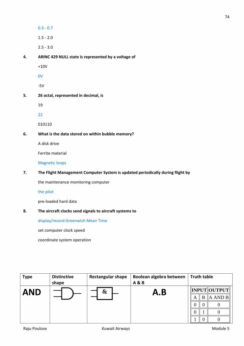
74
Raju Poulose Kuwait Airways Module 5
0.3 - 0.7
1.5 - 2.0
2.5 - 3.0
4. ARINC 429 NULL state is represented by a voltage of
+10V
0V
-5V
5. 26 octal, represented in decimal, is
19
22
010110
6. What is the data stored on within bubble memory?
A disk drive
Ferrite material
Magnetic loops
7. The Flight Management Computer System is updated periodically during flight by
the maintenance monitoring computer
the pilot
pre-loaded hard data
8. The aircraft clocks send signals to aircraft systems to
display/record Greenwich Mean Time
set computer clock speed
coordinate system operation
Type Distinctive shape
Rectangular shape Boolean algebra between A & B
Truth table
AND
A.B INPUT OUTPUT A B A AND B 0 0 0 0 1 0 1 0 0
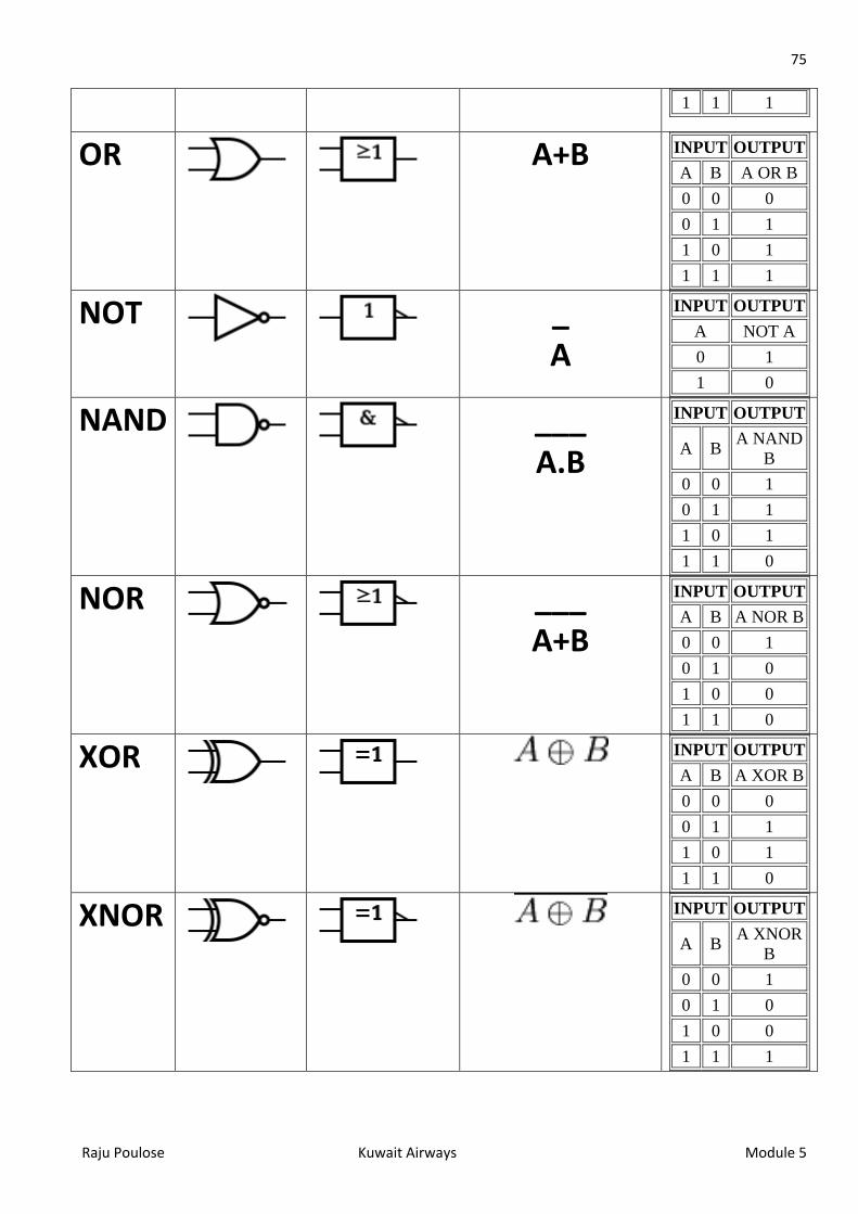
75
Raju Poulose Kuwait Airways Module 5
1 1 1
OR
A+B INPUT OUTPUT A B A OR B 0 0 0 0 1 1 1 0 1 1 1 1
NOT
_ A
INPUT OUTPUT A NOT A 0 1 1 0
NAND
___ A.B
INPUT OUTPUT
A B A NAND B
0 0 1 0 1 1 1 0 1 1 1 0
NOR
___ A+B
INPUT OUTPUT A B A NOR B 0 0 1 0 1 0 1 0 0 1 1 0
XOR
INPUT OUTPUT A B A XOR B 0 0 0 0 1 1 1 0 1 1 1 0
XNOR
INPUT OUTPUT
A B A XNOR B
0 0 1 0 1 0 1 0 0 1 1 1
Related Documents