University of Engineering and Technology Peshawar, Pakistan CE-409: Introduction to Structural Dynamics and Earthquake Engineering MODULE 2: FUNDAMENTAL PRINCIPLES OF EARTHQUAKE RESISTANT DESIGN PLANNING & CONSTRUCTION Prof. Dr. Akhtar Naeem Khan & Prof. Dr. Mohammad Javed [email protected] [email protected]

Module 2 (CE-409: Introduction to Structural Dynamics and Earthquake Engineering)
Sep 11, 2014
Welcome message from author
This document is posted to help you gain knowledge. Please leave a comment to let me know what you think about it! Share it to your friends and learn new things together.
Transcript
University of Engineering and Technology Peshawar, Pakistan
CE-409: Introduction to Structural Dynamics and Earthquake Engineering
MODULE 2: FUNDAMENTAL PRINCIPLES OF EARTHQUAKE
RESISTANT DESIGN PLANNING & CONSTRUCTION
Prof. Dr. Akhtar Naeem Khan & Prof. Dr. Mohammad Javed [email protected] [email protected]

CE-409: MODULE 2 ( Fall 2013)
What is Risk ?
2

CE-409: MODULE 2 ( Fall 2013)
Disaster
An event causing widespread human or material losses which exceeds the ability of the affected community to cope using its own resources
Risk?

CE-409: MODULE 2 ( Fall 2013)
Seismic Risk Seismic risk directly depends upon Seismic Hazard, Seismic
Vulnerability, and Exposure of elements at risk.
For the purpose of simplicity we will discuss only first two parameters Risk
4

CE-409: MODULE 2 ( Fall 2013)
Seismic Risk Seismic hazard depend on the geology of site and, therefore,
cannot be controlled.
Seismic vulnerability belong to structures and can ,therefore, be reduced by appropriate design and construction
Seismic Risk can be minimized by reducing seismic vulnerability of structures
5
CE-409: MODULE 2 ( Fall 2013) 6
The seismic risk keeps increasing
The current building stock is constantly enlarged by the addition of new buildings, many with significant, or even excessive, earthquake vulnerability. This is above all due to the fact that for new buildings, the basic principles of earthquake resistant design and also the earthquake specifications of the building codes, are often not followed.
The reason is either unawareness, convenience or intentional ignorance
As a result, the earthquake risk continues to increase unnecessarily.

CE-409: MODULE 2 ( Fall 2013) 7
Urgent Actions Needed
The preceding remarks clearly illustrate that there is a large deficit in the structural measures for seismic protection in many parts of the world.
New buildings must be designed to be reasonably earthquake resistant to prevent the constant addition of new vulnerable structures to a building stock that is already seriously threatened.
Your course “ Introduction to Structural dynamics and earthquake Engineering” aims at conveying the fundamental knowledge to the Civil Engineers regarding seismic resistant design and construction of structures

CE-409: MODULE 2 ( Fall 2013)
Some of the basic considerations for seismic design
8

CE-409: MODULE 2 ( Fall 2013)
Effect of relative stiffness on lateral forces distribution The lateral force is distributed (at a particular story level) in
proportion to the relative stiffness of the resisting members.
The applied forces are “attracted to” and concentrated at the
stiffer elements of the building.
Thus the engineer must calculate the stiffness of the resisting
elements to ascertain the forces that they must accommodate.
If two elements (two frames, walls, braces, or any combination)
are forced to deflect the same amount, and if one is stiffer, that one
will take more of the load.
9

CE-409: MODULE 2 ( Fall 2013)
The evaluation of relative rigidities is a necessary part of most
seismic analysis problems in order to determine the relative
distribution of the total horizontal force to the various resisting
elements.
An important aspect of this concept in relation to column lateral
stiffness is illustrated in figure .
Effect of relative stiffness on forces distribution
10

CE-409: MODULE 2 ( Fall 2013)
In the figure the columns have the same cross‑section, but the short column is half the length of the long one.
Effect of relative stiffness on forces distribution
11
450 lb
Mathematically, the stiffness of a column varies approximately as the cube of its length. Therefore, the short column will be eight times stiffer (23) instead of twice as stiff and will be subject to eight times the horizontal load of the long column. Stress is concentrated in the short column, while the long column is subject to nominal forces.

CE-409: MODULE 2 ( Fall 2013)
H.Assignment 1 (Module 2). HA1M2
10 k
10 ft 15 ft
Fig. 1
10 k
10 ft 15 ft
8 ft
Fig. 2
Draw S.F.D and B.M.D of given frames. Assume: 1. EI= Constant in all cases2. Beams are infinitely stiff in flexure. i.e. beam-column joints act as fixed supports

CE-409: MODULE 2 ( Fall 2013) 13
H.Assignment 1 (Module 2). HA1M2
10 k
10 ft
15 ft
8 ft
Fig. 3
100 ft.k
Calculate Bending Moment at all the supports of given frame. Assume (EI) column= (EI)beam/ 2. where EI for both beams are same
CE-409: MODULE 2 ( Fall 2013)
Torsional Forces
The center of mass, or center of gravity, of an object is the point
at which it could be exactly balanced without any rotation resulting.
If the mass (or weight) of a building is uniformly distributed (in
plan), the result is that the plan's geometric center (centroid) will
coincide with the center of mass.
In a building, the main lateral force is contributed by the weight of
the floors, walls, and roof, and this force is exerted through the center
of mass, usually the geometric center of the floor (in plan).
If the mass within a floor is uniformly distributed, then the resultant
force of the horizontal acceleration of all its particles is exerted
through the floor's geometric center
14

CE-409: MODULE 2 ( Fall 2013)
Torsional forces.
15
Torsional ForcesCentre of mass and rigidity
Centre of rigidity

CE-409: MODULE 2 ( Fall 2013)
Torsional Forces
Torsional forces are created in a building by a lack of balance between the location of the resisting elements and the arrangement of the building mass.
Engineers refer to this as eccentricity between the center of
mass and the center of rigidity, C.R. (or centre of stiffness),
which makes a building subjected to ground motion rotate around
its center of rigidity, creating torsion - a twisting action in plan,
which results in undesirable and possibly dangerous concentrations
of stress
16

CE-409: MODULE 2 ( Fall 2013)
In a building in which the mass is approximately evenly
distributed in plan (typical of a symmetrical building with uniform
floor, wall and column masses) the ideal arrangement is that the
earthquake resistant elements should be symmetrically placed, in
all directions
In practice, some degree of torsion is always present, and the
building code makes provision for this.
17
Torsional Forces
CE-409: MODULE 2 ( Fall 2013)
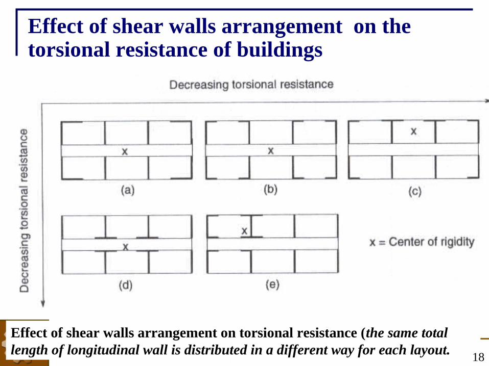
Effect of shear walls arrangement on the torsional resistance of buildings
Effect of shear walls arrangement on torsional resistance (the same total length of longitudinal wall is distributed in a different way for each layout. 18

CE-409: MODULE 2 ( Fall 2013)
Effect of shear walls arrangement on the torsional resistance of buildings
Greatest torsional resistance is obtained by concentrating the longitudinal walls at the comers of the building, as in Fig. a. The center of rigidity is at the center of the plan (from symmetry) and the longitudinal walls, being placed as distant as possible from this center, produce the greatest torsional resistance.
Although the position of the centre of rigidity of the symmetrical arrangement in Fig. b remains at the center of the plan, the longitudinal walls are not entirely placed at the extremities thus resulting in a reduced torsional resistance
19

CE-409: MODULE 2 ( Fall 2013)
Effect of shear walls arrangement on the torsional resistance of buildings
Because of lack of symmetry about one axis in Fig. c, the center of rigidity will move slightly off centroidal axis and lateral forces will have an increased torsional effect due to this offset of the center of rigidity. Also the distances from the center of rigidity of the flanged sections created with longitudinal walls have been reduced, thus reducing the torsional resistance.
Although the arrangement of walls in Fig. d is symmetrical, the longitudinal walls have been moved close to the center of rigidity and the sections produced have a greatly reduced influence on the torsional resistance of the total arrangement.
20

CE-409: MODULE 2 ( Fall 2013)
Effect of shear walls arrangement on the torsional resistance of buildings
A very poor arrangement of longitudinal walls is shown in Fig. e. Here they are clustered toward one comer, displacing the center of rigidity a large distance from the center of the plan and greatly increasing the torsional effects of the lateral loads. In addition, the longitudinal walls are at a short distance from the center of rigidity and therefore contribute less to the overall torsional resistance.
21

CE-409: MODULE 2 ( Fall 2013)
Non structural components
For many decades, seismic building codes focused exclusively on the
structure of the building—that is, the system of columns, beams, walls,
and diaphragms that provides resistance against earthquake forces.
Although this focus remains dominant for obvious reasons,
experience in more recent earthquakes has shown that damage to
nonstructural components is also of great concern.
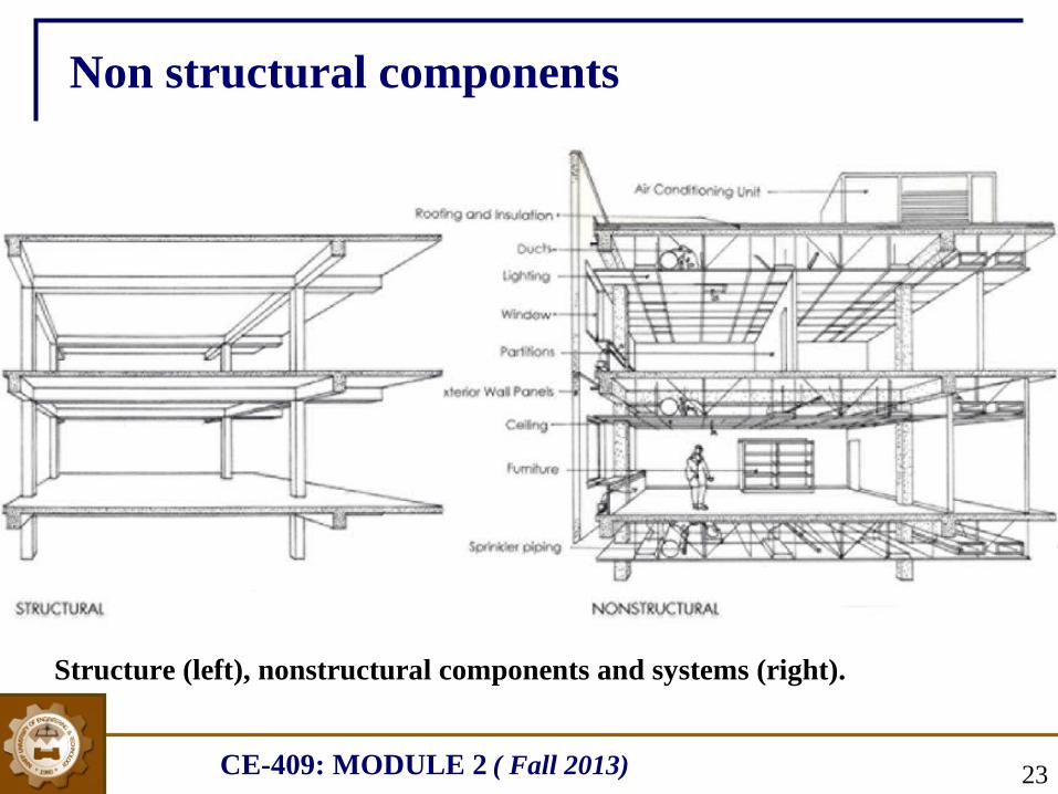
In most modern buildings, the nonstructural components account for
60 to 80 percent of the value of the building (figure on next slide). Most
nonstructural components are fragile (compared to the building
structure), easily damaged, and costly to repair or replace
22
CE-409: MODULE 2 ( Fall 2013)
Non structural components
Structure (left), nonstructural components and systems (right).
23

CE-409: MODULE 2 ( Fall 2013)
Non structural components The nonstructural elements (such as parapet walls, furniture video 1 start at 4:00 ,
video 2) if not properly anchored can impose serious threat to human lives.
Collapse of boundary walls and parapet walls were the cause of a significant number of fatalities during 2005 Kashmir earthquake.
The nonstructural components or systems may modify the structural response in ways detrimental to the safety of the building.
Examples are the placing of heavy nonstructural partitions in locations that result in severe torsion and stress concentration, or the placement of nonstructural partitions between columns in such a way as to produce a short column condition (video start at 1:00). This can lead to column failure, distortion, and further nonstructural damage.
Failure of the fire protection system, because of damage to the sprinkler system, may leave the building vulnerable to post-earthquake fires caused by electrical or gas system damage. 24
CE-409: MODULE 2 ( Fall 2013)
Some common mistakes resulting in reduced seismic resistance of structures
Four serious configurations conditions
25

CE-409: MODULE 2 ( Fall 2013)
Four serious configurations conditions
Four configuration conditions (two vertical and two in plan)
that originate in the architectural design and that have the
potential to seriously impact seismic performance are:
1.Soft and weak stories
2.Discontinuous shear walls
3.Variations in perimeter strength and stiffness
4.Re-entrant corners
26

CE-409: MODULE 2 ( Fall 2013)
Soft and Weak Stories The most prominent of the problems caused by severe stress
concentration is that of the “soft” story. The term has commonly been
applied to buildings whose ground-level story is less stiff than those
above.
The building code distinguishes between “soft” and “weak” stories.
Soft stories are less stiff, or more flexible, than the story above; weak
stories have less strength.
A soft or weak story at any height creates a problem, but since the
cumulative loads are greatest towards the base of the building, a
discontinuity between the first and second floor tends to result in the
most serious condition .
27

CE-409: MODULE 2 ( Fall 2013)
Soft-storey effect The most prominent of the problems caused by severe stress
concentration is that of the “soft” story.
The soft first story failure mechanism.
28

CE-409: MODULE 2 ( Fall 2013)
Lower story columns were collapsed in a hotel at Balakot, 2005 Kashmir earthquake
Avoid soft-storey ground floors!
29
Permanent plastic deformation in the ground floor of a building under construction. Soft story effect almost provoked a collapse (Friaul, Italy 1976).

CE-409: MODULE 2 ( Fall 2013)
Avoid soft-storey Upper floors!
Intermediate story columns are completely collapsed
Bagh, 2005 Kashmir earthquake
30
Kobe, Japan 1995.

CE-409: MODULE 2 ( Fall 2013)
Solutions
Add columns Add bracing Add external buttresses
31

CE-409: MODULE 2 ( Fall 2013)
Solutions
This apartment house appears to have a soft first story (Figure A), but the lateral force-resisting system is a strong internal shear wall box, in which the shear walls act as party walls between the dwelling units (Figure B).
32
Fig A Fig B

CE-409: MODULE 2 ( Fall 2013)
Avoid discontinuous Shear Walls
When shear walls form the main lateral resistant elements of a
structure, and there is not a continuous load path through the walls
from roof to foundation, the result can be serious overstressing at
the points of discontinuity. This discontinuous shear wall condition
represents a special, but common, case of the “soft” first-story
problem.
The discontinuous shear wall is a fundamental design
contradiction: the purpose of a shear wall is to collect diaphragm
loads at each floor and transmit them as directly and efficiently as
possible to the foundation. To interrupt this load path is undesirable.
33

CE-409: MODULE 2 ( Fall 2013)
Avoid discontinuous Shear Walls
Long section, Olive View Hospital. Note that the shear walls stop at the third floor.
Cross section, Olive View hospital, showing the second-floor plaza and the discontinuous shear wall.
34

CE-409: MODULE 2 ( Fall 2013)
Avoid discontinuous Shear Walls
Olive View hospital, San Fernando earthquake, 1971, showing the extreme deformation of the columns above the plaza level.
35

CE-409: MODULE 2 ( Fall 2013)
The solution to the problem of the discontinuous shear wall is to
eliminate the shear walls.
If the decision is made to use shear walls, then their presence
must be recognized from the beginning of schematic design, and
their size and location made the subject of careful architectural and
engineering coordination early.
Solutions
36

CE-409: MODULE 2 ( Fall 2013)
This problem may occur in buildings whose configuration is
geometrically regular and symmetrical, but nonetheless irregular
for seismic design purposes.
A building’s seismic behavior is strongly influenced by the
nature of the perimeter design. If there is wide variation in
strength and stiffness around the perimeter, the center of mass will
not coincide with the center of resistance, and torsional forces will
tend to cause the building to rotate around the center of resistance.
Variations in Perimeter Strength & Stiffness
37
CE-409: MODULE 2 ( Fall 2013)
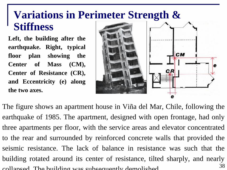
Left, the building after the earthquake. Right, typical floor plan showing the Center of Mass (CM), Center of Resistance (CR), and Eccentricity (e) along the two axes.
The figure shows an apartment house in Viña del Mar, Chile, following the
earthquake of 1985. The apartment, designed with open frontage, had only
three apartments per floor, with the service areas and elevator concentrated
to the rear and surrounded by reinforced concrete walls that provided the
seismic resistance. The lack of balance in resistance was such that the
building rotated around its center of resistance, tilted sharply, and nearly
collapsed. The building was subsequently demolished.
Variations in Perimeter Strength & Stiffness
38
CE-409: MODULE 2 ( Fall 2013)
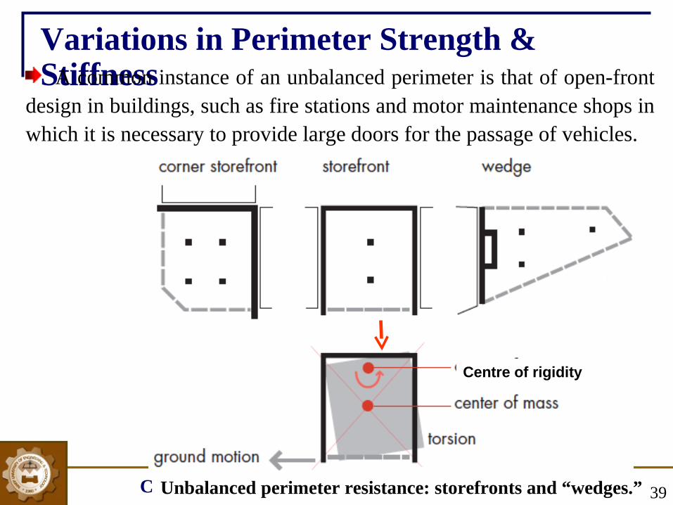
Variations in Perimeter Strength & Stiffness A common instance of an unbalanced perimeter is that of open-front
design in buildings, such as fire stations and motor maintenance shops in which it is necessary to provide large doors for the passage of vehicles.
Unbalanced perimeter resistance: storefronts and “wedges.” 39
Centre of rigidity

CE-409: MODULE 2 ( Fall 2013)
Variations in Perimeter Strength and Stiffness Stores, individually or as a group in a shopping mall, are often designed as
boxes with three solid sides and an open glazed front .
The large imbalance in perimeter strength and stiffness results in large torsional forces. Large buildings, such as department stores, that have unbalanced resistance on a number of floors to provide large window areas for
display are also common.
Penney’s store, Anchorage, Alaska, earthquake, 1964. Left: Damage to the store: Right: Second-floor plan, showing unbalanced perimeter resistance 40

CE-409: MODULE 2 ( Fall 2013)
Solutions The solution to this problem is to reduce the possibility of
torsion by endeavoring to balance the resistance around the
perimeter.
The first strategy is to design a frame structure of approximately
equal strength and stiffness for the entire perimeter
The opaque portion of the perimeter can be constructed of
nonstructural cladding, designed so that it does not affect the
seismic performance of the frame. This can be done either by using
lightweight cladding or by ensuring that heavy materials, such as
concrete or masonry, are isolated from the frame (Figure A)
41

CE-409: MODULE 2 ( Fall 2013)
Solutions
A second approach is to increase the stiffness of the open facades
by adding sufficient shear walls, at or near the open face, designed to
approach the resistance provided by the other walls (Figure B).
A third solution is to use a strong moment resisting or braced frame
at the open front, which approaches the solid wall in stiffness.
42

CE-409: MODULE 2 ( Fall 2013)
Solutions The ability to do this will depend on the size of the facades; a long
steel frame can never approach a long concrete wall in stiffness.
This is, however, a good solution for wood frame structures, such as small apartment buildings, or motels with ground floor garage areas, or small store fronts, because even a comparatively long steel frame can be made as stiff as plywood shear walls (Figure C).
43

CE-409: MODULE 2 ( Fall 2013)
Re-entrant Corners
The re-entrant corner is the common characteristic of building forms
that, in plan, assume the shape of an L, T, H, etc., or a combination
of these shapes
Re-entrant corner plan forms.
44

CE-409: MODULE 2 ( Fall 2013)
Re-entrant Corners
There are two problems created by these shapes. The first is that
they tend to produce differential motions between different wings of
the building that, because of stiff elements that tend to be located in
this region, result in local stress concentrations at the re-entrant corner.
The second problem of this form is torsion. Which is caused
because the center of mass and the center of rigidity in this form cannot
geometrically coincide for all possible earthquake directions. The result
is rotation. The resulting forces are very difficult to analyze and
predict.
45

CE-409: MODULE 2 ( Fall 2013)
Re-entrant Corners
46
Re-entrant corner
Centre of rigidity

CE-409: MODULE 2 ( Fall 2013)
Differential deformation at the junction of two wings
47

CE-409: MODULE 2 ( Fall 2013) 48

CE-409: MODULE 2 ( Fall 2013)
SolutionsThere are two basic alternative approaches to the problem of re-
entrant-corner forms: structurally to separate the building into
simpler shapes, or to tie the building together more strongly with
elements positioned to provide a more balanced resistance (see
figure ). The latter solution applies only to smaller buildings
Seperation Stiff resistant elements
In case of separation building must be sufficiently away to ensure they do not pound together and damage each other in an earthquake 49

CE-409: MODULE 2 ( Fall 2013) 50
SolutionsThe use of splayed rather than right angle re-entrant corners lessens the stress concentration
This is analogous to the way a tapered beam is structurally more desirable than an abruptly notched one.
Splayed re-entrant corners

CE-409: MODULE 2 ( Fall 2013)
Additional features (to be taken care of) to minimize structural damages
during an earthquake
51

CE-409: MODULE 2 ( Fall 2013)
The space between columns is sometimes filled in by a rigid
wall, leaving a short space for a clerestory window (a high
windows above eye level to bring outside light, fresh air, or both
into the inner space).
Such a simple act of remodeling may not seem to require
engineering analysis, and a contractor may be hired to do the work:
often such work is not subject to building department reviews and
inspection. Serious damage has occurred to buildings in
earthquakes because of this oversight.
Avoid short columns!
52
CE-409: MODULE 2 ( Fall 2013)
Avoid short columns!
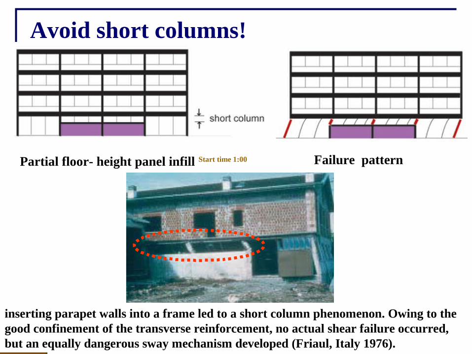
Partial floor- height panel infill Start time 1:00 Failure pattern
53
inserting parapet walls into a frame led to a short column phenomenon. Owing to the good confinement of the transverse reinforcement, no actual shear failure occurred, but an equally dangerous sway mechanism developed (Friaul, Italy 1976).

CE-409: MODULE 2 ( Fall 2013)
Avoid short columns!
54The diagonal cracks and shear failures in the short columns of a multi-storey car park almost caused collapse (Northridge, California 1994).
CE-409: MODULE 2 ( Fall 2013) 55
Redundancy in the structural system permits redistribution of internal forces in the event of failure of key elements.
After experience in many earthquakes and much study and discussion, the engineering profession has generally concluded that more than a single system is the ideal solution for successful seismic resistance.
If carefully selected, multiple systems can each serve a purpose; one to add damping and to limit deflection or drift, the other to provide strength.
Multiple systems also serve to protect the entire structure by allowing failure of some elements without endangering the total building.
Provide Redundancy

CE-409: MODULE 2 ( Fall 2013) 56
Redundancy in the structural system permits redistribution of internal forces in the event of failure of key elements.
After experience in many earthquakes and much study and discussion, the engineering profession has generally concluded that more than a single system is the ideal solution for successful seismic
resistance.
Provide Redundancy

CE-409: MODULE 2 ( Fall 2013) 57
The Hanshin Expressway after the 1995, Kobe Earthquake , Japan. Columns in the partially collapsed portion failed due to inadequate shear reinforcement. Existing soil conditions and lack of redundancy aggravated the situation
Provide Redundancy

CE-409: MODULE 2 ( Fall 2013) 58
If carefully selected, multiple systems can each serve a purpose; one
to add damping and to limit deflection or drift, the other to provide
strength.
Multiple systems also serve to protect the entire structure by allowing failure of some elements without endangering the total building.
An informative sketch of a classic redundant-framing concept, with
frames on each grid line, versus a contemporary multiple system with
two types of framing, one for strength, the other for damping, is shown
in figure on next slide.
The current dual systems now being developed and utilized are a
significant improvement over the historic single seismic resisting
systems.
Provide Redundancy
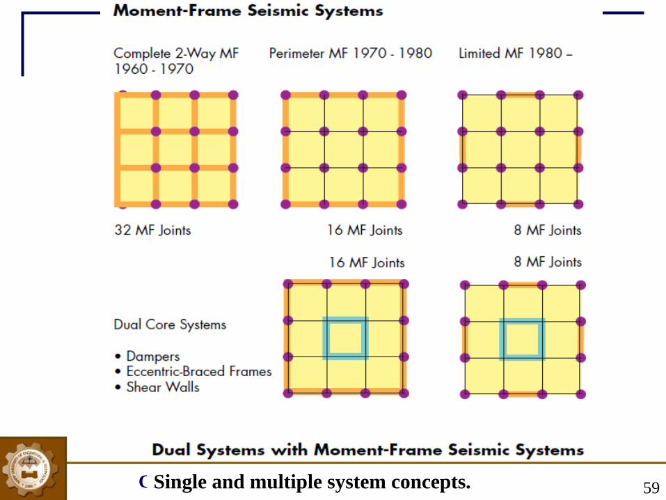
CE-409: MODULE 2 ( Fall 2013) 59Single and multiple system concepts.

CE-409: MODULE 2 ( Fall 2013)
Avoid strong beam- weak column
60
Strong beam-weak column joint simulates fixed support, resulting in larger moments at joint
Ground floor of an under construction commercial plaza (Muzzafarabad, 2005)

CE-409: MODULE 2 ( Fall 2013)
Inadequate lap of longitudinal bars in a collapsed column. Left (Abbotabad,2005), Right (Muzzafarabad,2005)
Provide Adequate Anchorage
61
CE-409: MODULE 2 ( Fall 2013)
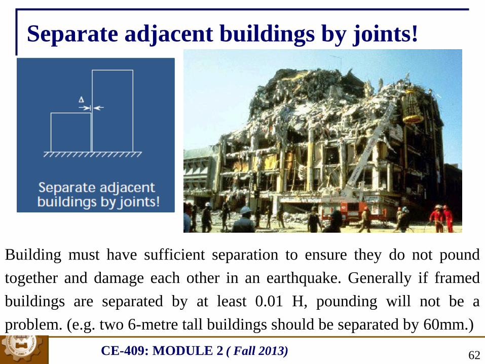
Separate adjacent buildings by joints!
Building must have sufficient separation to ensure they do not pound
together and damage each other in an earthquake. Generally if framed
buildings are separated by at least 0.01 H, pounding will not be a
problem. (e.g. two 6-metre tall buildings should be separated by 60mm.)
62

CE-409: MODULE 2 ( Fall 2013)
Separate adjacent buildings by joints!
63

CE-409: MODULE 2 ( Fall 2013)
Use closely spaced transverse reinforcement with 135° hooks in structural walls and columns!
64
Effect of confinement on the compressive strength of plain concrete specimens
σ2= σ3
σ 1
σ 1
90o hooks open up at relatively smaller force as compared to 135o hooks

CE-409: MODULE 2 ( Fall 2013) 65
Use closely spaced transverse reinforcement with 135° hooks in structural walls and columns!
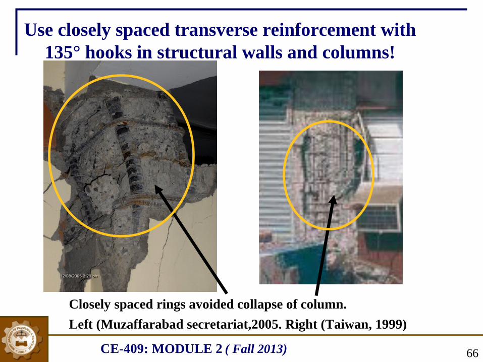
Largely spaced rings resulted in failure of column (due to spalling of concrete from rings) in a building at Abbotabad during 2005 Kashmir earthquake
CE-409: MODULE 2 ( Fall 2013)
Closely spaced rings avoided collapse of column.
Left (Muzaffarabad secretariat,2005. Right (Taiwan, 1999)
Use closely spaced transverse reinforcement with 135° hooks in structural walls and columns!
66
CE-409: MODULE 2 ( Fall 2013) 67
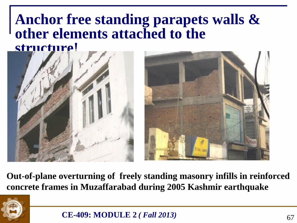
Anchor free standing parapets walls & other elements attached to the structure!
Out-of-plane overturning of freely standing masonry infills in reinforced concrete frames in Muzaffarabad during 2005 Kashmir earthquake
CE-409: MODULE 2 ( Fall 2013) 68
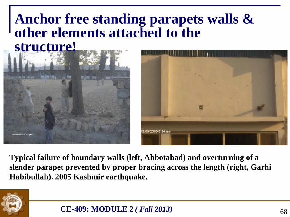
Typical failure of boundary walls (left, Abbotabad) and overturning of a slender parapet prevented by proper bracing across the length (right, Garhi Habibullah). 2005 Kashmir earthquake.
Anchor free standing parapets walls & other elements attached to the structure!
CE-409: MODULE 2 ( Fall 2013) 69
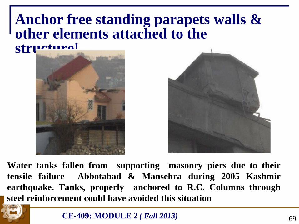
Water tanks fallen from supporting masonry piers due to their tensile failure Abbotabad & Mansehra during 2005 Kashmir earthquake. Tanks, properly anchored to R.C. Columns through steel reinforcement could have avoided this situation
Anchor free standing parapets walls & other elements attached to the structure!

CE-409: MODULE 2 ( Fall 2013)
Various mechanisms to dissipate energy imparted to a structure by an
earthquake
70

CE-409: MODULE 2 ( Fall 2013)
Response of a building with no base isolation is shown in Figure a.
Where, response of the building with base isolation can be simulated by Figure
b, where the rollers move during ground shaking but the building above does
not move and no force is transferred to the building due to shaking.
Base Isolation
(a) (b)
71
CE-409: MODULE 2 ( Fall 2013)
Base isolation is carried out, mostly, by using
i. Laminated rubber bearing (LRB)
ii. Spherical Sliding Isolation Systems
Lead-rubber bearings (LRB) are among the frequently-used
types of base isolation bearings. (See figure on next slide)
An LRB is made from layers of rubber sandwiched together
with layers of steel. In the middle of the bearing is a solid lead
"plug." On top and bottom, the bearing is fitted with steel
plates which are used to attach the bearing to the building and
foundation. The bearing is very stiff and strong in the vertical
direction, but flexible in the horizontal direction.
Base Isolation
72

CE-409: MODULE 2 ( Fall 2013)
The bearing is very stiff
and strong in the vertical
direction, but flexible in the
horizontal direction.
a) Laminated rubber bearing (LRB).
Lead-Rubber Bearing
Lead plug in the middle of bearing experiences the same deformation
as the rubber. However, it also generates heat as it does so. In other
words, the lead plug reduces, or dissipates, the energy of motion--
i.e., kinetic energy--by converting that energy into heat
Base Isolation
73

CE-409: MODULE 2 ( Fall 2013)
a) Laminated rubber bearing (LRB).
Experiments and observations of base-isolated buildings in earthquakes have been shown to reduce building accelerations video1,
video 2 to as little as 1/4 of the acceleration of comparable fixed-base buildings, Increase or decrease in acceleration proportionally increases or decreases inertial force as inertial forces are directly related to
acceleration (FI = ma).
Base Isolation
74Building resting directly on ground Building base isolated with LRB (large displacements and acc. In building) (lower displacement and acc. in building)

CE-409: MODULE 2 ( Fall 2013)
Lead-rubber bearings are just one of a number of different types of base isolation bearings which have now been developed. Spherical Sliding Isolation Systems are another type of base isolation. The building is supported by bearing pads that have a curved surface and low friction.
Spherical Sliding Isolation Bearing
b) Spherical Sliding Isolation Systems .Base Isolation
75

CE-409: MODULE 2 ( Fall 2013) 76
The force needed to move the building upwards limits the
horizontal or lateral forces (
Transformation of K.E into P.E & vice versa) which would
otherwise cause building deformations.
b) Spherical Sliding Isolation Systems .Base Isolation
It should be noted that base isolation is not suitable for tall high rise buildings or buildings located on soft soil.
Base isolation is most effective for short to medium rise buildings located on hard soil.

CE-409: MODULE 2 ( Fall 2013)
Under a simple harmonic load, one can show that the main mass
can be kept completely stationary when the natural time period (of
the
attached absorber is chosen to be (or tuned to) the time period of excitation
.
During an earthquake or wind , TMD will move against the
direction of main structural vibration and an inertia force will be
acted on the structure to reduce the response of the structure .
TMD are effective in controlling wind induced excessive
vibration in high rise buildings due to one specific value of time
period of tuned mass. However, multiple tuned mass dampers have
also been devised to control vibration during earthquake
corresponding to important modes
Tuned Mass Damper (TMD)
77

CE-409: MODULE 2 ( Fall 2013) 78
H.Assignment 2 (Module 2). HA2M2
1. Can we reduce the seismic risk of an existing building stock? Support your answer with argument(s)
2. What will be your strategy as a design engineer to avoid soft story effect at a floor (other than ground floor) without providing any wall?
3. How you will cope, as a design engineer, where you cannot avoid short columns?
4. How you will handle a situation as a design engineer where you cannot change the x-sectional dimensions of a very stiff beam connected to a flexible column?
5. Suggest at least two methods of bracing the boundary walls.
Related Documents


