AutoCAD Module 1B: 1B- Points, Lines, & Planes in the Three-Dimensional Space 1 Module 1B Points, Lines, & Planes in the Three-Dimensional Space This learning module will explore the basic drafting conventions traditionally used in the solution of descriptive geometry problems, and the basic approach in solving problems involving the relationships among points, lines and planes in the three- dimensional pace. The students can • Use the Points, Lines, & Planes in the Three-Dimensional Space Problems file inside the Exercise Problems folder, in the Student Descriptive Geometry Learning Resource CD by copying the entire folder to a disk (or USB flash drive). This file is saved in AutoCAD 2000/LT2000 Drawing [*.dwg] format, and can be opened in any version of AutoCAD 2000, LT 2000 or higher. In this file, each given problems is accompanied with a title that corresponds to the title given in this learning module, the labels of the views (top, front and right, etc.), lines representing the viewing planes with labels (F|P, F H , etc.), and given geometric entities (points, lines, etc.) with labels (A H , B H , A P , B P , etc.), as shown in Figure 1B-1A; or Figure 1B-1A: A given problem in the given file. Figure 1B-1B: Basic principles of orthographic projections across the three principal views. © Edward Locke 2007 ([email protected]) FOR EDUCATIONAL USE ONLY. ALL RIGHTS RESERVED.

Welcome message from author
This document is posted to help you gain knowledge. Please leave a comment to let me know what you think about it! Share it to your friends and learn new things together.
Transcript

AutoCAD Module 1B: 1B- Points, Lines, & Planes in the Three-Dimensional Space
1
Module 1B Points, Lines, & Planes in the
Three-Dimensional Space
This learning module will explore the basic drafting conventions traditionally used in the solution of descriptive geometry problems, and the basic approach in solving problems involving the relationships among points, lines and planes in the three-dimensional pace. The students can
• Use the Points, Lines, & Planes in the Three-Dimensional Space Problems
file inside the Exercise Problems folder, in the Student Descriptive Geometry Learning Resource CD by copying the entire folder to a disk (or USB flash drive). This file is saved in AutoCAD 2000/LT2000 Drawing [*.dwg] format, and can be opened in any version of AutoCAD 2000, LT 2000 or higher. In this file, each given problems is accompanied with a title that corresponds to the title given in this learning module, the labels of the views (top, front and
right, etc.), lines representing the viewing planes with labels (F|P, FH , etc.),
and given geometric entities (points, lines, etc.) with labels (AH, BH, AP, BP, etc.), as shown in Figure 1B-1A; or
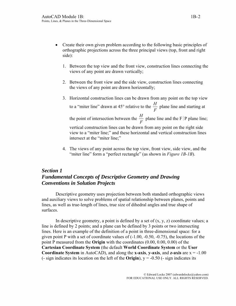
Figure 1B-1A: A given problem in the given file.
Figure 1B-1B: Basic principles of orthographic projections across the three principal views.
© Edward Locke 2007 ([email protected]) FOR EDUCATIONAL USE ONLY. ALL RIGHTS RESERVED.
AutoCAD Module 1B: 1B- Points, Lines, & Planes in the Three-Dimensional Space
2
• Create their own given problem according to the following basic principles of orthographic projections across the three principal views (top, front and right side):
1. Between the top view and the front view, construction lines connecting the
views of any point are drawn vertically; 2. Between the front view and the side view, construction lines connecting
the views of any point are drawn horizontally;
3. Horizontal construction lines can be drawn from any point on the top view
to a “miter line” drawn at 45° relative to the FH plane line and starting at
the point of intersection between the FH plane line and the F|P plane line;
vertical construction lines can be drawn from any point on the right side view to a “miter line;” and these horizontal and vertical construction lines intersect at the “miter line;”
4. The views of any point across the top view, front view, side view, and the
“miter line” form a “perfect rectangle” (as shown in Figure 1B-1B).
Section 1 Fundamental Concepts of Descriptive Geometry and Drawing Conventions in Solution Projects
Descriptive geometry uses projection between both standard orthographic views and auxiliary views to solve problems of spatial relationship between planes, points and lines, as well as true-length of lines, true size of dihedral angles and true shape of surfaces.
In descriptive geometry, a point is defined by a set of (x, y, z) coordinate values; a
line is defined by 2 points; and a plane can be defined by 3 points or two intersecting lines. Here is an example of the definition of a point in three-dimensional space: for a given point P with a set of coordinate values of (-1.00, -0.50, -0.75), the locations of the point P measured from the Origin with the coordinates (0.00, 0.00, 0.00) of the Cartesian Coordinate System (the default World Coordinate System or the User Coordinate System in AutoCAD), and along the x-axis, y-axis, and z-axis are x = -1.00 (- sign indicates its location on the left of the Origin), y = -0.50 (- sign indicates its
© Edward Locke 2007 ([email protected]) FOR EDUCATIONAL USE ONLY. ALL RIGHTS RESERVED.
AutoCAD Module 1B: 1B- Points, Lines, & Planes in the Three-Dimensional Space
3
location below the Origin), z = -0.75 (- sign indicates its location away from the viewer from the Origin). Notice that in theory, any point in three-dimensional space should be described with three (x, y, z) coordinate values; however, in two-dimensional drawings using AutoCAD, the point on either the default XY Plane of the World Coordinate System or the user-defined XY Plane of the User Coordinate System, which can be created with the various options of the UCS tool, can be defined by typing only two coordinate values (x, y) in the Command Line entry.
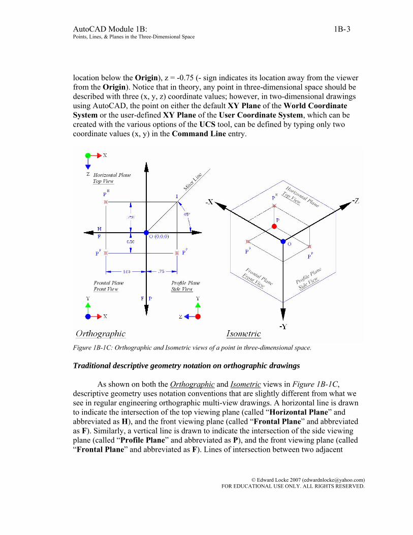
Figure 1B-1C: Orthographic and Isometric views of a point in three-dimensional space. Traditional descriptive geometry notation on orthographic drawings
As shown on both the Orthographic and Isometric views in Figure 1B-1C, descriptive geometry uses notation conventions that are slightly different from what we see in regular engineering orthographic multi-view drawings. A horizontal line is drawn to indicate the intersection of the top viewing plane (called “Horizontal Plane” and abbreviated as H), and the front viewing plane (called “Frontal Plane” and abbreviated as F). Similarly, a vertical line is drawn to indicate the intersection of the side viewing plane (called “Profile Plane” and abbreviated as P), and the front viewing plane (called “Frontal Plane” and abbreviated as F). Lines of intersection between two adjacent
© Edward Locke 2007 ([email protected]) FOR EDUCATIONAL USE ONLY. ALL RIGHTS RESERVED.
AutoCAD Module 1B: 1B- Points, Lines, & Planes in the Three-Dimensional Space
4
viewing planes are called “folding lines” and can be drawn in phantom lines. The Top View is drawn on the Horizontal Plane. The Front View is drawn on the Frontal Plane. The Side View is drawn on the Profile Plane.
A point on any of the three orthographic views is labeled with a capital or lower-case letter with a superscript h (or t, for “top”), f (for “front”), and p (or s for “side”) for its view on the horizontal plane (top view), frontal plane (front view), and profile plane (side view) respectively. The superscript can be a capital (H or T, F, P or S) or a lower-case letter (h or t, f, r or s); and they can be omitted altogether.
On the orthographic drawing, the projected point P on the top, front and right side
views are related to each other as follows: between top and front views, by a vertical construction line; between front and side views, by a horizontal construction line; between top and right side views, by a set of vertical and a horizontal construction lines which intersect at point I on a 45° miter line drawn from the origin point O; As shown, points P on the side, front, top views and point I form a perfect rectangle. Section 2 Points in Three-dimensional Space
In this part of the module, we will explore some AutoCAD tools in finding the information about points and in creating objects used in the solution of descriptive geometry problems. Creating a point in a three-dimensional space and obtaining related information in AutoCAD
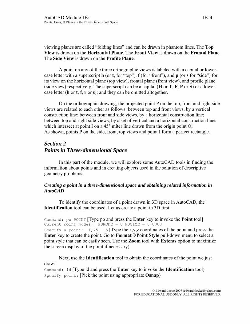
To identify the coordinates of a point drawn in 3D space in AutoCAD, the Identification tool can be used. Let us create a point in 3D first: Command: po POINT [Type po and press the Enter key to invoke the Point tool] Current point modes: PDMODE = 0 PDSIZE = 0.0000 Specify a point: -1,75,-.5 [Type the x,y,z coordinates of the point and press the Enter key to create the point. Go to Format Point Style pull-down menu to select a point style that can be easily seen. Use the Zoom tool with Extents option to maximize the screen display of the point if necessary)
Next, use the Identification tool to obtain the coordinates of the point we just draw: Command: id [Type id and press the Enter key to invoke the Identification tool) Specify point: [Pick the point using appropriate Osnap)
© Edward Locke 2007 ([email protected]) FOR EDUCATIONAL USE ONLY. ALL RIGHTS RESERVED.

AutoCAD Module 1B: 1B- Points, Lines, & Planes in the Three-Dimensional Space
5
X = -1.0000 Y = 75.0000 Z = -0.5000 [The Command Line gives the coordinates of the point] Measuring the distance between two points in the three-dimensional space
The distance measurements made between two points in a three-dimensional space along the X-axis, or Y-axis, or Z-axis is called Delta-X, or Delta-Y, or Delta-Z respectively. Sometimes, Greek symbol Δ is used for “Delta” (For example: ΔX = -1.00, ΔY = - 0.50, ΔZ = - 0.75). ΔX = the distance between two points measured along the X-axis; ΔY = the distance between two points measured along the Y-axis; ΔY = the distance between two points measured along the Z-axis.
If we draw point P and O in an AutoCAD 3D drawing by using the Point tool
with (x,y,z) coordinates entry, and then use the Line tool with Node Osnap the draw a line between point P and O (Figure 1B-2A), we can use the List or Property tool to find the “Delta” values.
Figure 1B-2A: Creating the points O and P (left), and the connecting line (right).
Command: po [Type po and press Enter to invoke the Point tool] POINT Current point modes: PDMODE = 35 PDSIZE = 0.000 Specify a point: -1,.75,-.5 [Type the coordinates for point P; and press the Enter key twice] Specify a point: 0,0,0 [Type the coordinates for point O; and press the Enter key] Command: l LINE [Type l and press the Enter key to invoke the Line tool] Specify first point: 0,0,0 [Type coordinates for point O, press the Enter key] Specify next point or [Undo]: nod of [Type nod and press the Enter key to invoke the Node Osnap, move the cursor near point P and click when the Node Osnap indicator shows; and then press the Enter key to end the command] Command: '_.properties [Double-click the line to open the Properties dialog and obtain the “Delta,” Length and other information]. OR Command: list [Type list and press Enter to invoke the List tool] Select objects: 1 found [Click the line and press Enter to end selection].
© Edward Locke 2007 ([email protected]) FOR EDUCATIONAL USE ONLY. ALL RIGHTS RESERVED.
AutoCAD Module 1B: 1B- Points, Lines, & Planes in the Three-Dimensional Space
6
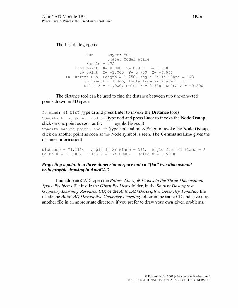
The List dialog opens: LINE Layer: "0" Space: Model space Handle = D75 from point, X= 0.000 Y= 0.000 Z= 0.000 to point, X= -1.000 Y= 0.750 Z= -0.500 In Current UCS, Length = 1.250, Angle in XY Plane = 143 3D Length = 1.346, Angle from XY Plane = 338 Delta X = -1.000, Delta Y = 0.750, Delta Z = -0.500
The distance tool can be used to find the distance between two unconnected points drawn in 3D space.
Command: di DIST (type di and press Enter to invoke the Distance tool) Specify first point: nod of (type nod and press Enter to invoke the Node Osnap, click on one point as soon as the Node symbol is seen) Specify second point: nod of (type nod and press Enter to invoke the Node Osnap, click on another point as soon as the Node symbol is seen. The Command Line gives the distance information) Distance = 74.1434, Angle in XY Plane = 272, Angle from XY Plane = 3 Delta X = 3.0000, Delta Y = -74.0000, Delta Z = 3.5000 Projecting a point in a three-dimensional space onto a “flat” two-dimensional orthographic drawing in AutoCAD
Launch AutoCAD, open the Points, Lines, & Planes in the Three-Dimensional
Space Problems file inside the Given Problems folder, in the Student Descriptive Geometry Learning Resource CD; or the AutoCAD Descriptive Geometry Template file inside the AutoCAD Descriptive Geometry Learning folder in the same CD and save it as another file in an appropriate directory if you prefer to draw your own given problems.
© Edward Locke 2007 ([email protected]) FOR EDUCATIONAL USE ONLY. ALL RIGHTS RESERVED.
AutoCAD Module 1B: 1B- Points, Lines, & Planes in the Three-Dimensional Space
7
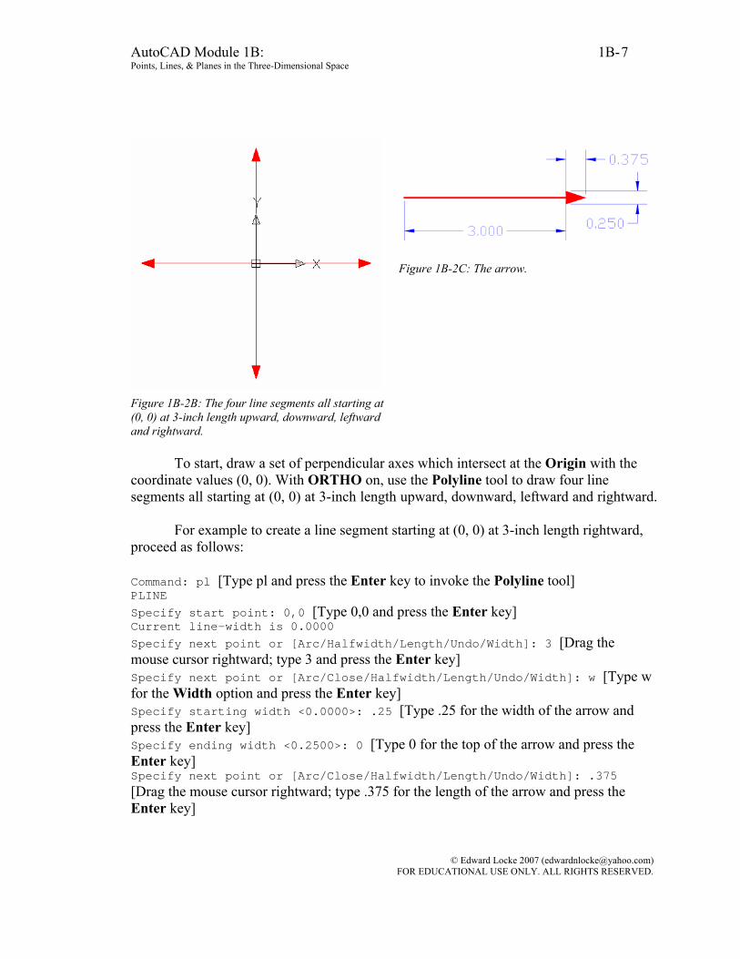
Figure 1B-2B: The four line segments all starting at (0, 0) at 3-inch length upward, downward, leftward and rightward.
Figure 1B-2C: The arrow.
To start, draw a set of perpendicular axes which intersect at the Origin with the
coordinate values (0, 0). With ORTHO on, use the Polyline tool to draw four line segments all starting at (0, 0) at 3-inch length upward, downward, leftward and rightward.
For example to create a line segment starting at (0, 0) at 3-inch length rightward,
proceed as follows: Command: pl [Type pl and press the Enter key to invoke the Polyline tool] PLINE Specify start point: 0,0 [Type 0,0 and press the Enter key] Current line-width is 0.0000 Specify next point or [Arc/Halfwidth/Length/Undo/Width]: 3 [Drag the mouse cursor rightward; type 3 and press the Enter key] Specify next point or [Arc/Close/Halfwidth/Length/Undo/Width]: w [Type w for the Width option and press the Enter key] Specify starting width <0.0000>: .25 [Type .25 for the width of the arrow and press the Enter key] Specify ending width <0.2500>: 0 [Type 0 for the top of the arrow and press the Enter key] Specify next point or [Arc/Close/Halfwidth/Length/Undo/Width]: .375 [Drag the mouse cursor rightward; type .375 for the length of the arrow and press the Enter key]
© Edward Locke 2007 ([email protected]) FOR EDUCATIONAL USE ONLY. ALL RIGHTS RESERVED.

AutoCAD Module 1B: 1B- Points, Lines, & Planes in the Three-Dimensional Space
8
Specify next point or [Arc/Close/Halfwidth/Length/Undo/Width]: [Press the Enter key to exit the tool; Press the Enter key again to invoke the tool] Next, follow similar steps to create the remaining three line segments, starting at (0, 0), at 3-inch length upward, downward, and leftward (Figure 1B-2B and Figure 1B-2C).
Next, locate the projected points on the top, front and side views. Since an orthographic drawing is a two-dimensional or “flat” one, each view can include only a set of two coordinate values. We can imagine the top, front and right side views as three folded-up “glass panels” which are perpendicular to each other (Figure 1B-2D). Under this default setting, the top view (the “horizontal plane”) contains the projected X, Z coordinates; the front view (the “frontal plane”) contains the projected X, Y coordinates; the right side view (the “profile plane”) contains the projected Y, Z coordinates. We then make measurements from the Origin point O with construction lines parallel to the axis lines to locate the projected points across three orthographic views (in AutoCAD, we can use the Offset tool to create these construction lines from the axes line). This is analogous to opening up the “glass panels.”
Notice that, as shown in Figure 1B-2E and Figure 1B-2F, the projection of any
point across the three principal orthographic views satisfies the following principles: • Between the front view and the top view (as well as the bottom view), the
projection runs vertically, since the front, top and bottom views share the same width dimensions;
• Between the front view and the side view (as well as rear view), the projection
runs horizontally, since the all “elevation” views (left side, right side, front and rear) share the same height dimensions;
• The depth dimensions between the top view and the side view can be
transferred by the “miter line” method to be discussed in the next few paragraphs;
• The projection of any point across the three principal views and the “miter
line” forms a perfect rectangle.
© Edward Locke 2007 ([email protected]) FOR EDUCATIONAL USE ONLY. ALL RIGHTS RESERVED.

AutoCAD Module 1B: 1B- Points, Lines, & Planes in the Three-Dimensional Space
9
Figure 1B-2D: The “glass panels” (left); the three orthographic views (right).
Figure 1B-2F: Folded-up three-dimensional “glass panels” (left); orthogonal views of each panel (right.)
© Edward Locke 2007 ([email protected]) FOR EDUCATIONAL USE ONLY. ALL RIGHTS RESERVED.
AutoCAD Module 1B: 1B- Points, Lines, & Planes in the Three-Dimensional Space
10
Section 3 Creating a Point with Given Coordinates in AutoCAD’s Three-dimensional Space and Drawing the Three Principal Orthographic Views of the Point in an AutoCAD Two-dimensional Plan
In this section, we will learn how to create a point with given coordinates with given xyz coordinates (2, -5, 4), in AutoCAD’s three-dimensional space; and to draw the three principal orthographic views of the point in an AutoCAD two-dimensional plan. Creating a point in AutoCAD’s three-dimensional space
To start, let us analyze these coordinate values and their relationships with the Origin (0, 0, 0) of the default WCS (World Coordinate System) in AutoCAD.
The given xyz coordinates (2, -5, 4) indicate that: • The point is 2 units on the right of the Origin along the x-axis (The first
number of the coordinates is the x-value, which indicate the distance from the Origin to given point along the horizontal x-axis; if the value is positive, then the point is on the right of the Origin; and if the value is negative, then the point is on the left of the Origin);
• The point is 5 units beneath the Origin along the y-axis (The second number
of the coordinates is the y-value, which indicate the distance from the Origin to given point along the vertical y-axis; if the value is positive, then the point is above the Origin; and if the value is negative, then the point is beneath the Origin);
• The point is 4 units in front of the Origin along the z-axis (The third number
of the coordinates is the z-value, which indicate the distance from the Origin to given point along the z-axis, which extends from the Origin toward or away from the viewer; if the value is positive, then the point is in front of the Origin; and if the value is negative, then the point is behind of the Origin).
© Edward Locke 2007 ([email protected]) FOR EDUCATIONAL USE ONLY. ALL RIGHTS RESERVED.
AutoCAD Module 1B: 1B- Points, Lines, & Planes in the Three-Dimensional Space
11
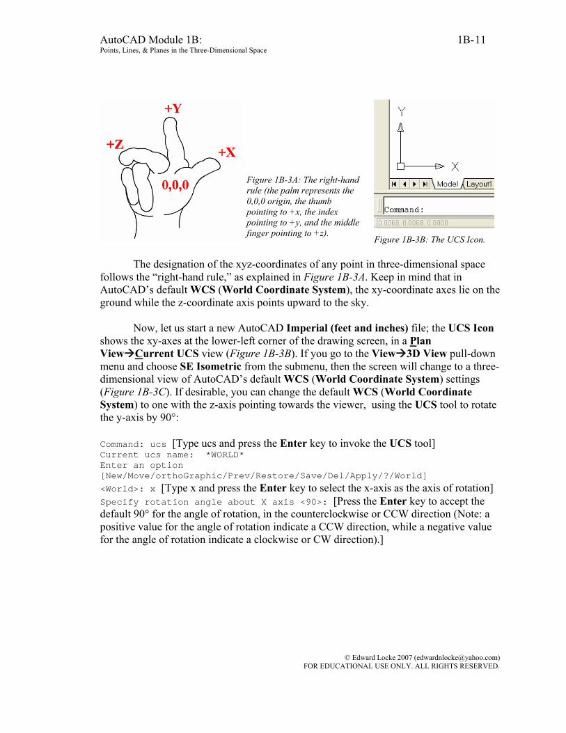
Figure 1B-3A: The right-hand rule (the palm represents the 0,0,0 origin, the thumb pointing to +x, the index pointing to +y, and the middle finger pointing to +z).
Figure 1B-3B: The UCS Icon.
The designation of the xyz-coordinates of any point in three-dimensional space follows the “right-hand rule,” as explained in Figure 1B-3A. Keep in mind that in AutoCAD’s default WCS (World Coordinate System), the xy-coordinate axes lie on the ground while the z-coordinate axis points upward to the sky.
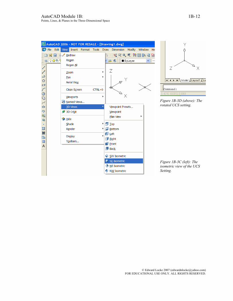
Now, let us start a new AutoCAD Imperial (feet and inches) file; the UCS Icon
shows the xy-axes at the lower-left corner of the drawing screen, in a Plan View Current UCS view (Figure 1B-3B). If you go to the View 3D View pull-down menu and choose SE Isometric from the submenu, then the screen will change to a three-dimensional view of AutoCAD’s default WCS (World Coordinate System) settings (Figure 1B-3C). If desirable, you can change the default WCS (World Coordinate System) to one with the z-axis pointing towards the viewer, using the UCS tool to rotate the y-axis by 90°:
Command: ucs [Type ucs and press the Enter key to invoke the UCS tool] Current ucs name: *WORLD* Enter an option [New/Move/orthoGraphic/Prev/Restore/Save/Del/Apply/?/World] <World>: x [Type x and press the Enter key to select the x-axis as the axis of rotation] Specify rotation angle about X axis <90>: [Press the Enter key to accept the default 90° for the angle of rotation, in the counterclockwise or CCW direction (Note: a positive value for the angle of rotation indicate a CCW direction, while a negative value for the angle of rotation indicate a clockwise or CW direction).]
© Edward Locke 2007 ([email protected]) FOR EDUCATIONAL USE ONLY. ALL RIGHTS RESERVED.
AutoCAD Module 1B: 1B- Points, Lines, & Planes in the Three-Dimensional Space
12
Figure 1B-3D (above): The rotated UCS setting. Figure 1B-3C (left): The isometric view of the UCS Setting.
© Edward Locke 2007 ([email protected]) FOR EDUCATIONAL USE ONLY. ALL RIGHTS RESERVED.
AutoCAD Module 1B: 1B- Points, Lines, & Planes in the Three-Dimensional Space
13
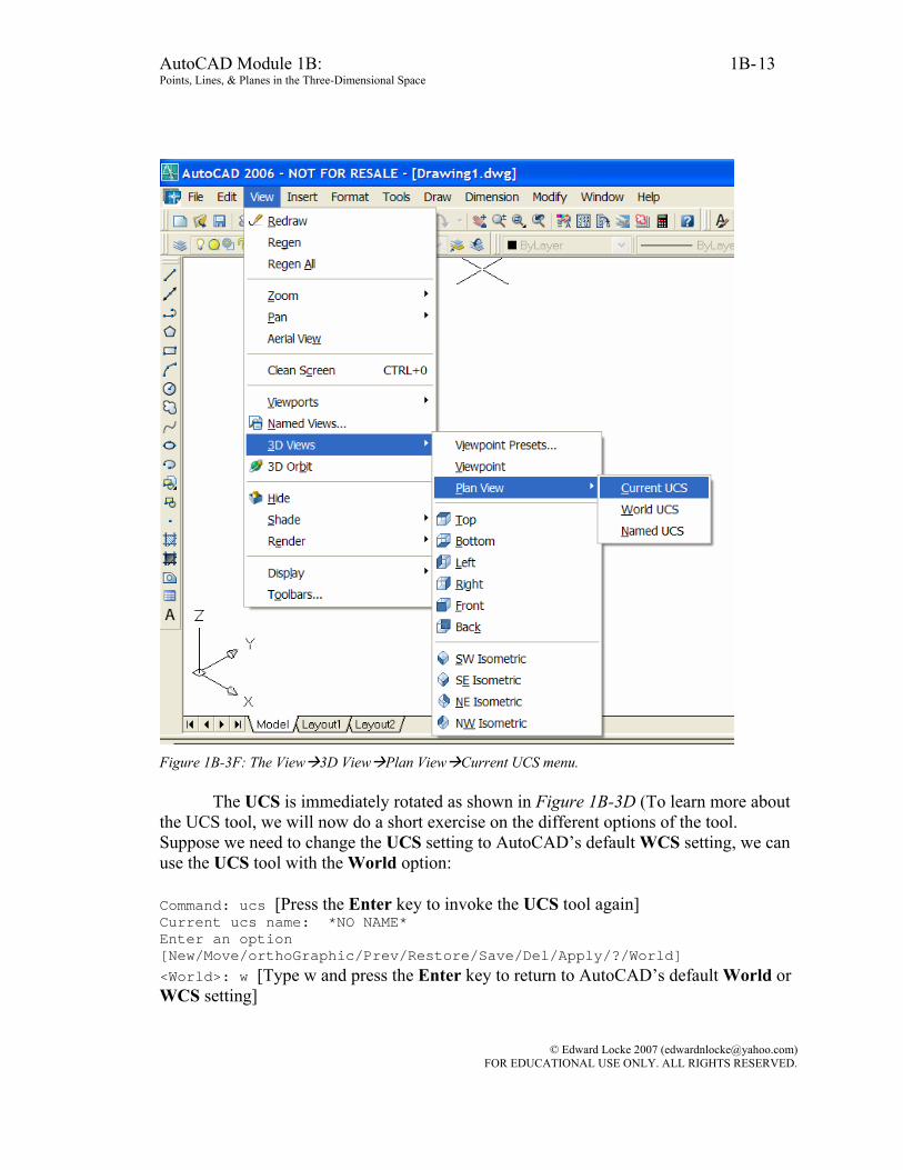
Figure 1B-3F: The View 3D View Plan View Current UCS menu.
The UCS is immediately rotated as shown in Figure 1B-3D (To learn more about the UCS tool, we will now do a short exercise on the different options of the tool. Suppose we need to change the UCS setting to AutoCAD’s default WCS setting, we can use the UCS tool with the World option:
Command: ucs [Press the Enter key to invoke the UCS tool again] Current ucs name: *NO NAME* Enter an option [New/Move/orthoGraphic/Prev/Restore/Save/Del/Apply/?/World] <World>: w [Type w and press the Enter key to return to AutoCAD’s default World or WCS setting]
© Edward Locke 2007 ([email protected]) FOR EDUCATIONAL USE ONLY. ALL RIGHTS RESERVED.
AutoCAD Module 1B: 1B- Points, Lines, & Planes in the Three-Dimensional Space
14
We will now return the UCS to a previous setting, we can use the UCS tool with the Prev option: Command: ucs [Press the Enter key to invoke the UCS tool again] Current ucs name: *NO NAME* Enter an option [New/Move/orthoGraphic/Prev/Restore/Save/Del/Apply/?/World] <World>: w [Type p and press the Enter key to return to the previous UCS setting]
Note: if you need to return to the orthographic plane view f the current xy-plane,
then go to the View 3D View pull-down menu and choose Plan View Current UCS from the submenu; the screen changes to the default Plan View of the UCS setting (Figure 1B-3F).
We can now create the point in AutoCAD’s three-dimensional space, using the Point tool: Command: po [Type po and press the Enter key to invoke the Point tool] POINT Current point modes: PDMODE=0 PDSIZE=0.0000 Specify a point: 2,-5,4 [Type the values of xyz-coordinates 2,-5,4 and press the Enter key to create the point (Note: There should be no space between the x,y,z coordinate values)]
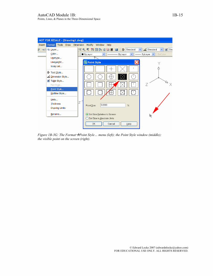
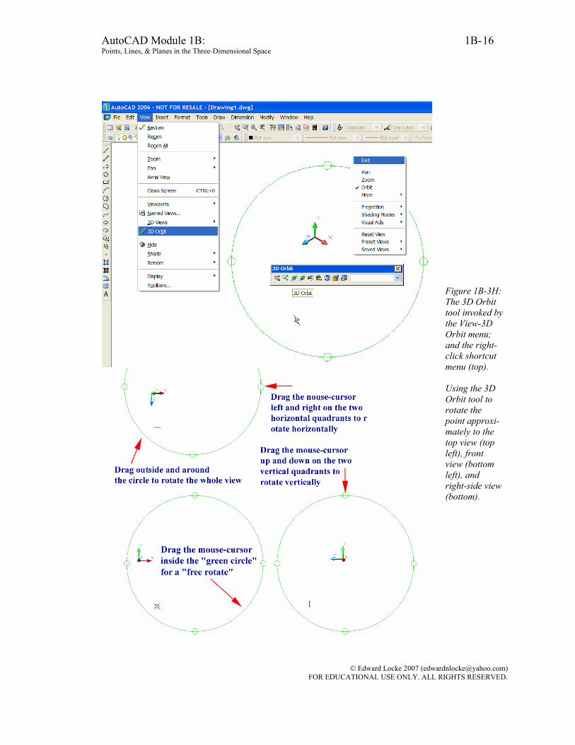
The point is created but is not visible. To make the point visible, go to the
Format Point Style… menu; choose a desired Point Style and click the OK button; the point becomes visible on the screen (Figure 1B-3G). To help visualize the distance between the point created and the Origin, the 3D Orbit tool can be used to rotate the point to its approximate front view, top view and right-side view. Go to the View 3D Orbit menu to invoke this tool; and drag the mouse-cursor to rotate the UCS icon; right-click for the tool’s shortcut menu and select the Exit option to exit the tool (See Figure 1B-3H).
© Edward Locke 2007 ([email protected]) FOR EDUCATIONAL USE ONLY. ALL RIGHTS RESERVED.
AutoCAD Module 1B: 1B- Points, Lines, & Planes in the Three-Dimensional Space
15
Figure 1B-3G: The Format Point Style… menu (left); the Point Style window (middle); the visible point on the screen (right).
© Edward Locke 2007 ([email protected]) FOR EDUCATIONAL USE ONLY. ALL RIGHTS RESERVED.
AutoCAD Module 1B: 1B- Points, Lines, & Planes in the Three-Dimensional Space
16
Figure 1B-3H: The 3D Orbit tool invoked by the View-3D Orbit menu; and the right-click shortcut menu (top). Using the 3D Orbit tool to rotate the point approxi-mately to the top view (top left), front view (bottom left), and right-side view (bottom).
© Edward Locke 2007 ([email protected]) FOR EDUCATIONAL USE ONLY. ALL RIGHTS RESERVED.

AutoCAD Module 1B: 1B- Points, Lines, & Planes in the Three-Dimensional Space
17
Figure 1B-3J: Exiting the 3D Orbit tool and using the ID Point tool with the help of the Node Object Snap.
Figure 1B-3K: The Tools Inquiry ID Point menu.
Next, we exit the 3D Orbit tool with the Exit option in the right-click shortcut menu; and use the ID Point tool to verify the coordinates of the point we have created: Command: id [Type id and press the Enter key to invoke the ID Point tool] Specify point: nod of [Type nod for the Node Object Snap; move the mouse-cursor close to the point, and click once at the appearance of the Node indicator on the screen. Figure 1B-3J] X = 2.0000 Y = -5.0000 Z = 4.0000 [The Command Line displays the coordinates of the point]
© Edward Locke 2007 ([email protected]) FOR EDUCATIONAL USE ONLY. ALL RIGHTS RESERVED.
AutoCAD Module 1B: 1B- Points, Lines, & Planes in the Three-Dimensional Space
18
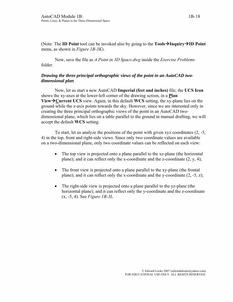
(Note: The ID Point tool can be invoked also by going to the Tools Inquiry ID Point menu, as shown in Figure 1B-3K).
Now, save the file as A Point in 3D Space.dwg inside the Exercise Problems folder. Drawing the three principal orthographic views of the point in an AutoCAD two-dimensional plan
Now, let us start a new AutoCAD Imperial (feet and inches) file; the UCS Icon
shows the xy-axes at the lower-left corner of the drawing screen, in a Plan View Current UCS view. Again, in this default WCS setting, the xy-plane lies on the ground while the z-axis points towards the sky. However, since we are interested only in creating the three principal orthographic views of the point in an AutoCAD two-dimensional plane, which lies on a table parallel to the ground in manual drafting, we will accept the default WCS setting.
To start, let us analyze the positions of the point with given xyz coordinates (2, -5,
4) in the top, front and right-side views. Since only two coordinate values are available on a two-dimensional plane, only two coordinate values can be reflected on each view:
• The top view is projected onto a plane parallel to the xz-plane (the horizontal
plane); and it can reflect only the x-coordinate and the z-coordinate (2, y, 4); • The front view is projected onto a plane parallel to the xy-plane (the frontal
plane); and it can reflect only the x-coordinate and the y-coordinate (2, -5, z);
• The right-side view is projected onto a plane parallel to the yz-plane (the horizontal plane); and it can reflect only the y-coordinate and the z-coordinate (x, -5, 4). See Figure 1B-3L.
© Edward Locke 2007 ([email protected]) FOR EDUCATIONAL USE ONLY. ALL RIGHTS RESERVED.

AutoCAD Module 1B: 1B- Points, Lines, & Planes in the Three-Dimensional Space
19
Figure 1B-3L: The three coordinate planes i.e., xy-plane, yz-plane and xz-plane (Top left). The three principal planes (Top right):
• The horizontal plane (parallel to the xz-plane) for the top view;
• The frontal plane (parallel to the xy-plane) for the front view;
• The profile plane (parallel to the yz-plane) for the right-side view.
The projection of the point (2,-5,4) onto the horizontal plane, frontal plane and profile plane (Bottom left). The three principal views (Bottom right).
© Edward Locke 2007 ([email protected]) FOR EDUCATIONAL USE ONLY. ALL RIGHTS RESERVED.
AutoCAD Module 1B: 1B- Points, Lines, & Planes in the Three-Dimensional Space
20
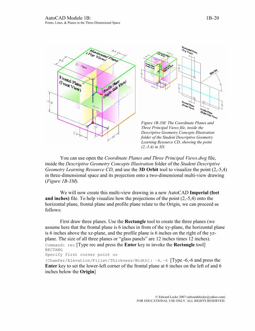
Figure 1B-3M: The Coordinate Planes and Three Principal Views file, inside the Descriptive Geometry Concepts Illustration folder of the Student Descriptive Geometry Learning Resource CD, showing the point (2,-5,4) in 3D.
You can use open the Coordinate Planes and Three Principal Views.dwg file,
inside the Descriptive Geometry Concepts Illustration folder of the Student Descriptive Geometry Learning Resource CD, and use the 3D Orbit tool to visualize the point (2,-5,4) in three-dimensional space and its projection onto a two-dimensional multi-view drawing (Figure 1B-3M).
We will now create this multi-view drawing in a new AutoCAD Imperial (feet and inches) file. To help visualize how the projections of the point (2,-5,4) onto the horizontal plane, frontal plane and profile plane relate to the Origin, we can proceed as follows:
First draw three planes. Use the Rectangle tool to create the three planes (we
assume here that the frontal plane is 6 inches in from of the xy-plane, the horizontal plane is 6 inches above the xz-plane, and the profile plane is 6 inches on the right of the yz-plane. The size of all three planes or “glass panels” are 12 inches times 12 inches). Command: rec [Type rec and press the Enter key to invoke the Rectangle tool] RECTANG Specify first corner point or [Chamfer/Elevation/Fillet/Thickness/Width]: -6,-6 [Type -6,-6 and press the Enter key to set the lower-left corner of the frontal plane at 6 inches on the left of and 6 inches below the Origin]
© Edward Locke 2007 ([email protected]) FOR EDUCATIONAL USE ONLY. ALL RIGHTS RESERVED.
AutoCAD Module 1B: 1B- Points, Lines, & Planes in the Three-Dimensional Space
21
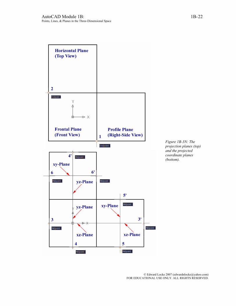
Specify other corner point or [Area/Dimensions/Rotation]: 6,6 [Type 6,6 and press the Enter key to set the top-right corner of the frontal plane at 6 inches on the right of and 6 inches above the Origin. Press the Enter key to invoke the Rectangle tool again] Command: RECTANG Specify first corner point or [Chamfer/Elevation/Fillet/Thickness/Width]: end [Type end and press the Enter key to invoke the Endpoint Object Snap] Of [Move the mouse-cursor close to point 1 and click once at the appearance of the Endpoint Object Snap indicator] Specify other corner point or [Area/Dimensions/Rotation]: @12,12 [Type @12,12 and press the Enter key to create the profile plane. Press the Enter key again to invoke the Rectangle tool] Command: RECTANG Specify first corner point or [Chamfer/Elevation/Fillet/Thickness/Width]: end [Type end and press the Enter key to invoke the Endpoint Object Snap] Of Move the mouse-cursor close to point 2 and click once at the appearance of the Endpoint Object Snap indicator] Specify other corner point or [Area/Dimensions/Rotation]: @12,12 Type @12,12 and press the Enter key to create the horizontal plane] The three planes (the horizontal plane, frontal plane, and profile plane) are created on the screen. We will next draw the projections of the coordinate planes (xy-plane, xz-plane and yz-plane) on all three planes (Figure 1B-1U). Command: l [Type l and press the Enter key to invoke the Line tool] LINE Specify first point: mid [Type mid and press the Enter key to invoke the Midpoint Object Snap] Of [Move the mouse-cursor close to point 3 and click once at the appearance of the Midpoint Object Snap indicator] Specify next point or [Undo]: mid [Type mid and press the Enter key to invoke the Midpoint Object Snap again] Of [Move the mouse-cursor close to point 3’, and click once at the appearance of the Midpoint Object Snap indicator. The projection of the xz-plane is created on the frontal plane and the profile plane. Press the Enter key to invoke the Line tool again. Use the pairs of Midpoints 4-4’, 5-5’, and 6-6’ to create the other coordinate planes as show in Figure 1B-3N. When finished, press the Enter key to exit the Line tool]
© Edward Locke 2007 ([email protected]) FOR EDUCATIONAL USE ONLY. ALL RIGHTS RESERVED.
AutoCAD Module 1B: 1B- Points, Lines, & Planes in the Three-Dimensional Space
22
Figure 1B-3N: The projection planes (top) and the projected coordinate planes (bottom).
© Edward Locke 2007 ([email protected]) FOR EDUCATIONAL USE ONLY. ALL RIGHTS RESERVED.
AutoCAD Module 1B: 1B- Points, Lines, & Planes in the Three-Dimensional Space
23
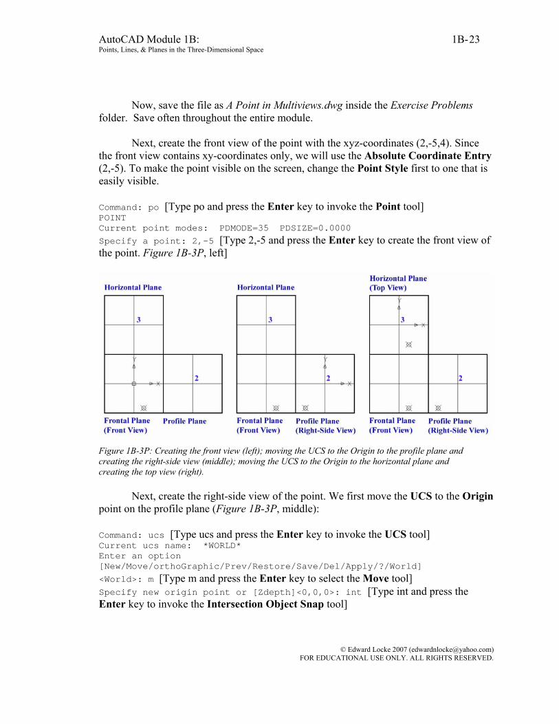
Now, save the file as A Point in Multiviews.dwg inside the Exercise Problems folder. Save often throughout the entire module.
Next, create the front view of the point with the xyz-coordinates (2,-5,4). Since
the front view contains xy-coordinates only, we will use the Absolute Coordinate Entry (2,-5). To make the point visible on the screen, change the Point Style first to one that is easily visible.
Command: po [Type po and press the Enter key to invoke the Point tool] POINT Current point modes: PDMODE=35 PDSIZE=0.0000 Specify a point: 2,-5 [Type 2,-5 and press the Enter key to create the front view of the point. Figure 1B-3P, left]
Figure 1B-3P: Creating the front view (left); moving the UCS to the Origin to the profile plane and creating the right-side view (middle); moving the UCS to the Origin to the horizontal plane and creating the top view (right).
Next, create the right-side view of the point. We first move the UCS to the Origin point on the profile plane (Figure 1B-3P, middle):
Command: ucs [Type ucs and press the Enter key to invoke the UCS tool] Current ucs name: *WORLD* Enter an option [New/Move/orthoGraphic/Prev/Restore/Save/Del/Apply/?/World] <World>: m [Type m and press the Enter key to select the Move tool] Specify new origin point or [Zdepth]<0,0,0>: int [Type int and press the Enter key to invoke the Intersection Object Snap tool]
© Edward Locke 2007 ([email protected]) FOR EDUCATIONAL USE ONLY. ALL RIGHTS RESERVED.
AutoCAD Module 1B: 1B- Points, Lines, & Planes in the Three-Dimensional Space
24
Of [Move the mouse-cursor close to point 2 and click once at the appearance of the Intersection Object Snap indicator] Since the right-side view contains the yz-coordinates only; on the right-side view, the horizontal axis represents the z-axis, the z-coordinate of the point is 4, therefore, the point is 4 inches on the left of the Origin; and we will use the Absolute Coordinate Entry (-4,-5): Command: po [Type po and press the Enter key to invoke the Point tool] POINT Current point modes: PDMODE=35 PDSIZE=0.0000 Specify a point: -4,-5 [Type -4,-5 and press the Enter key to create the right-side view of the point]
Next, create the top view of the point. We first move the UCS to the Origin point on the profile plane (Figure 1B-1V, right):
Command: ucs [Type ucs and press the Enter key to invoke the UCS tool] Current ucs name: *WORLD* Enter an option [New/Move/orthoGraphic/Prev/Restore/Save/Del/Apply/?/World] <World>: m [Type m and press the Enter key to select the Move tool] Specify new origin point or [Zdepth]<0,0,0>: int [Type int and press the Enter key to invoke the Intersection Object Snap tool] Of [Move the mouse-cursor close to point 3 and click once at the appearance of the Intersection Object Snap indicator] Since the top view contains the zx-coordinates only; on the top view, the vertical axis represents the z-axis, the z-coordinate of the point is 4, therefore, the point is 4 inches below the Origin, we will use the Absolute Coordinate Entry (2,-4): Command: po [Type po and press the Enter key to invoke the Point tool] POINT Current point modes: PDMODE=35 PDSIZE=0.0000 Specify a point: 2,-4 [Type 2,-4 and press the Enter key to create the right-side view of the point]
Now, return the UCS to default setting. Command: ucs [Type ucs and press the Enter key to invoke the UCS tool] Current ucs name: *NO NAME* Enter an option [New/Move/orthoGraphic/Prev/Restore/Save/Del/Apply/?/World] <World>: w [Type w and press the Enter key to return to the default the WCS setting]
© Edward Locke 2007 ([email protected]) FOR EDUCATIONAL USE ONLY. ALL RIGHTS RESERVED.
AutoCAD Module 1B: 1B- Points, Lines, & Planes in the Three-Dimensional Space
25
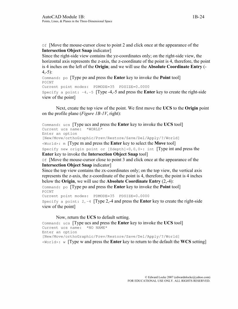
Figure 1B-3R: The L-shape connection among the top, front and right-side views of the point (left). The dimensions of the point on the top, front and right-side views (right). The repetitions of the width, height and depth dimensions across all three views are for the sole purpose of illustration.
All three principal views of the point are created. Notice that the three views of
the point has an L-shape alignment (Figure 1B-3Q). This proves that first two of the following three fundamental principles of orthographic projection are true:
• Between the front and side views, the projection lines run horizontally, since
the front and side views share the same height dimensions; • Between the front and top views, the projection lines run vertically, since the
front and top views share the same width dimensions;
• The top and side views share the same depth dimensions. As a matter of fact, if we need to draw the three principal views of only one point,
we just need to create one view with the Point tool (a point view, as shown in Figure 1B-3R, we create the front view first), and then create the other two adjacent views with the Copy tool and the ORTHO turn on (by pressing the F8 key):
Command: co COPY [Type co and press the Enter key to invoke the Copy tool] Select objects: [Click-select the point (the front view)] 1 found
© Edward Locke 2007 ([email protected]) FOR EDUCATIONAL USE ONLY. ALL RIGHTS RESERVED.

AutoCAD Module 1B: 1B- Points, Lines, & Planes in the Three-Dimensional Space
26
Select objects: [Press the Enter key to end selection] Specify base point or [Displacement] <Displacement>: Specify second point or [Click any convenient point on the screen and drag the mouse-cursor upward] <use first point as displacement>: *Cancel* [Click once at a reasonable distance above the front view to create the top view of the point] Specify second point or [Exit/Undo] <Exit>: [Drag the mouse-cursor to the right of the front view, and click once at a reasonable distance on the right of the front view to create the right-side view of the point] Specify second point or [Exit/Undo] <Exit>: [Press the Enter key to exit the tool]
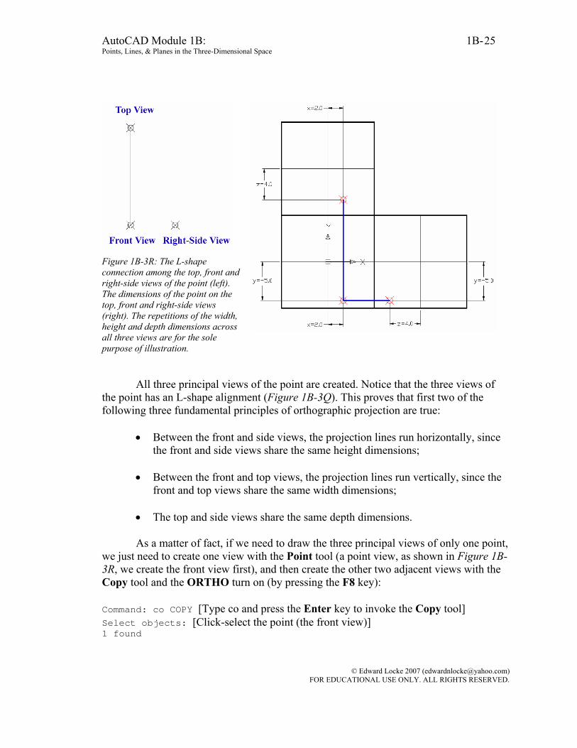
Figure 1B-3R: Creating the front view with the Point tool, and the top and right-side views with Copy tool and ORTHO Setting (left and middle). The complete views (right).
Drawing the three principal orthographic views of another point
Suppose we want to add a second point Q with the xyz-coordinates (3, -6, 2) in the top, front and right-side views. We can first calculate the differences between the corresponding x, y and z coordinates of the two points (called Delta X, Delta Y and Delta Z in AutoCAD), and then use the Copy tool and the Relative Coordinate Entry method to create the three views of the point Q.
Between the points P (2, -5, 4) and Q (3, -6, 2) and, the values of Delta X, Delta
Y and Delta Z are: 123 =−=−=Δ PQ xxx , ( ) 156 −=−−−=−=Δ PQ yyy , and . Therefore, the values for the Relative Coordinate Entry in
the three views should be: 242 −=−=−=Δ PQ zzz
• For the front view: the delta values are ( ) ( )1,1, −=ΔΔ yx ; and this leads to a
Relative Coordinate Entry of (1,-1);
© Edward Locke 2007 ([email protected]) FOR EDUCATIONAL USE ONLY. ALL RIGHTS RESERVED.
AutoCAD Module 1B: 1B- Points, Lines, & Planes in the Three-Dimensional Space
27
• For the right-side view: the delta values are ( ) ( )1,2, −−=ΔΔ yz ; the -2 value for ZΔ indicates that the point Q is 2 inches behind the point P (when the viewer look at the point Q from the front view); however, on the right-side view, the horizontal axis is the z-axis, and the point Q is on the right of the point P; and this leads to a Relative Coordinate Entry of (2,-1), since in AutoCAD’s Relative Coordinate Entry convention, a right-ward move corresponds to a positive value;
• For the top view: the delta values are ( ) ( )2,1, −=ΔΔ zx ; on the top view, the
vertical axis is the z-axis, and the point Q is above the point P; and this leads to a Relative Coordinate Entry of (1,2), since in AutoCAD’s Relative Coordinate Entry convention, a up-ward move corresponds to a positive value.
Use the Copy tool and the Relative Coordinate Entry method to create the top,
front and right-side view of the point Q (Figure 1B-3S): Command: co [Type co and press the Enter key to invoke the Copy tool] COPY Select objects: 1 found [Click-select the point PF] Select objects: [Enter] [Press the Enter key to end selection] Specify base point or [Displacement] <Displacement>: Specify second point or <use first point as displacement>: [Click any point close to PF on the screen] Specify second point or <use first point as displacement>: @1,-1 [Type @1,-1 as the Relative Coordinate Entry and press the Enter key to create the front view of point Q, QF] Specify second point or [Exit/Undo] <Exit>: [Press the Enter key to exit the tool. Press the Enter key to invoke the Copy tool again] Command: co COPY Select objects: [Click-select the point PH] 1 found Select objects: [Press the Enter key to end selection] Specify base point or [Displacement] <Displacement>: [Click any point close to PH on the screen] Specify second point or <use first point as displacement>: @1,2 [Type @1,2 as the Relative Coordinate Entry and press the Enter key to create the top view of point Q, QH] Specify second point or [Exit/Undo] <Exit>: [Press the Enter key to exit the tool. Press the Enter key to invoke the Copy tool again] Command: co COPY Select objects: [Click-select the point PP]
© Edward Locke 2007 ([email protected]) FOR EDUCATIONAL USE ONLY. ALL RIGHTS RESERVED.
AutoCAD Module 1B: 1B- Points, Lines, & Planes in the Three-Dimensional Space
28
1 found Select objects: [Press the Enter key to end selection] Specify base point or [Displacement] <Displacement>: [Click any point close to PP on the screen] Specify second point or <use first point as displacement>: @2,1 [Type @2,1 as the Relative Coordinate Entry and press the Enter key to create the right-side view of point Q, QP] Specify second point or [Exit/Undo] <Exit>: [Press the Enter key to exit the tool]
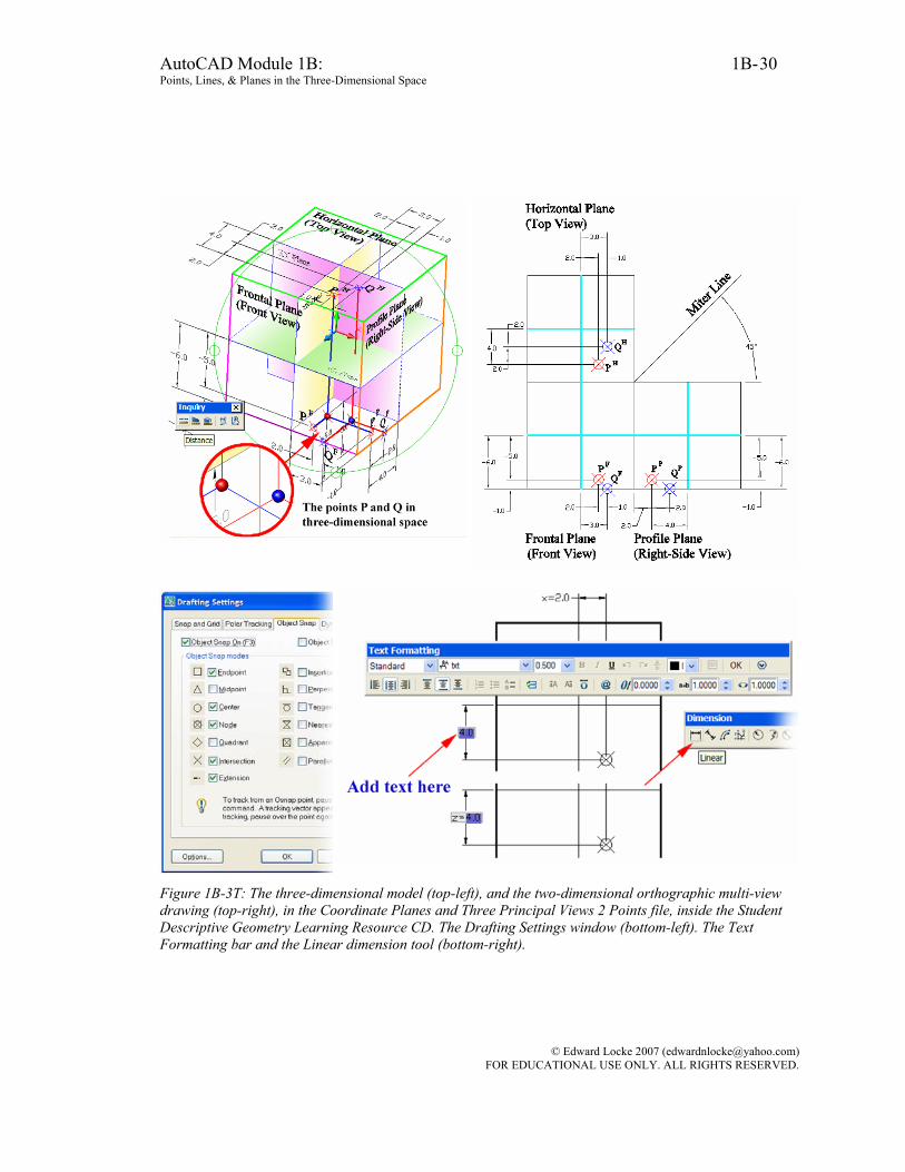
Students can easily visualize the points P and Q in three-dimensional space, as well as the relationship between their relative positions and their projections onto the top, front and right-side views, in the Coordinate Planes and Three Principal Views 2 Points file inside the Student Descriptive Geometry Learning Resource CD, with the 3D Orbit tool (Figure 1B-3T, top-left and top-right). please note that the repetitions of the width, height and depth dimensions in both the three-dimensional model and the two-dimensional projection drawing in the file are for the sole purpose of illustration, and should never be done in normal drawings (according to drafting conventions, the same dimensions should never be repeated in different views). For the correct placement of dimensions, running Object Snap should be used. To set up running Object Snap, type ds and press the Enter key to open the Drafting Settings dialog window, check the items under the Object Snap tab and click the OK button. The Linear dimension tool is used in the file. The notes attached to the dimension figure, such as z = in z = 4.0, are added by the ddedit command (Figure 1B-1Z, bottom-left); to use this tool, type ddedit in the Command Line and press the Enter key; click-select the dimension; the Text Formatting bar opens, and the dimension figure text turn blue with a cursor flashing at the start; type the note and then click the OK button close to the top-right corner of the bar to finish (the ←and → arrow keys on the keyboard can be used to move the cursor to the end of the dimension figure text, and vice versa. In addition, to delete the dimension figure text, click the text which immediately turns green; then type the new text over it and click the OK button).
© Edward Locke 2007 ([email protected]) FOR EDUCATIONAL USE ONLY. ALL RIGHTS RESERVED.
AutoCAD Module 1B: 1B- Points, Lines, & Planes in the Three-Dimensional Space
29
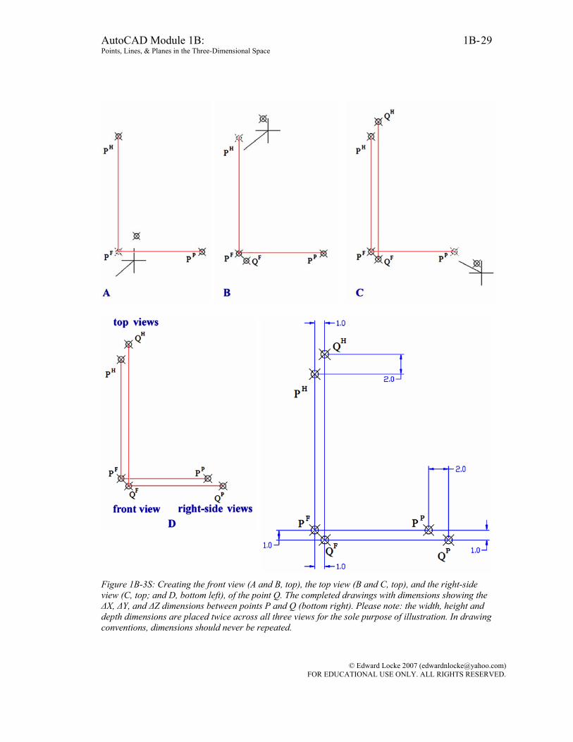
Figure 1B-3S: Creating the front view (A and B, top), the top view (B and C, top), and the right-side view (C, top; and D, bottom left), of the point Q. The completed drawings with dimensions showing the ΔX, ΔY, and ΔZ dimensions between points P and Q (bottom right). Please note: the width, height and depth dimensions are placed twice across all three views for the sole purpose of illustration. In drawing conventions, dimensions should never be repeated.
© Edward Locke 2007 ([email protected]) FOR EDUCATIONAL USE ONLY. ALL RIGHTS RESERVED.
AutoCAD Module 1B: 1B- Points, Lines, & Planes in the Three-Dimensional Space
30
Figure 1B-3T: The three-dimensional model (top-left), and the two-dimensional orthographic multi-view drawing (top-right), in the Coordinate Planes and Three Principal Views 2 Points file, inside the Student Descriptive Geometry Learning Resource CD. The Drafting Settings window (bottom-left). The Text Formatting bar and the Linear dimension tool (bottom-right).
© Edward Locke 2007 ([email protected]) FOR EDUCATIONAL USE ONLY. ALL RIGHTS RESERVED.
AutoCAD Module 1B: 1B- Points, Lines, & Planes in the Three-Dimensional Space
31
Determining the distance between the two point
As mentioned before, between the points P (2, -5, 4) and Q (3, -6, 2) and, the values of Delta X, Delta Y and Delta Z are: 123 =−=−=Δ PQ xxx ,
( ) 156 −=−−−=−=Δ PQ yyy , and 242 −=−=−=Δ PQ zzz . The distance between the two points can be determined by the formulas:
( ) ( ) ( )222222PQPQPQ zzyyxxzyxd −+−+−=Δ+Δ+Δ=
Thus, ( ) ( ) ( ) 449489743.26211 222 ≈=−+−+=d
The distance between the points P (2, -5, 4) and Q (3, -6, 2) can also be determined graphically on the three-dimensional model. In the Coordinate Planes and Three Principal Views 2 Points file inside the Student Descriptive Geometry Learning Resource CD, use the Distance tool (this tool can be invoked by going to the Tools Inquiry Distance menu, or by the Command Line shortcut method): Command: di DIST [Type di and press the Enter key to invoke the Distance tool] Specify first point: nod of [Type nod and press the Enter key to invoke the Node Object Snap. Move the mouse-cursor close to the red sphere that represents the point P, and click-once at the appearance of the Node indicator] Specify second point: nod of [Type nod and press the Enter key to invoke the Node Object Snap. Move the mouse-cursor close to the blue sphere that represents the point Q, and click-once at the appearance of the Node indicator] Distance = 2.4495, Angle in XY Plane = 135, Angle from XY Plane = 55 Delta X = -1.0000, Delta Y = 1.0000, Delta Z = 2.0000 [The Command Line displays the Distance and all other information regarding the points P and Q] Note: In this file, two spheres centered at the points P and Q have been created for the purpose of illustration; since a Center Object Snap exists at the center of any sphere, therefore, the Center Object Snap can be used instead of the Node Object Snap in the use of the Distance tool, and the result will be the same.
The distance between the points P (2, -5, 4) and Q (3, -6, 2) can also be determined graphically with two-dimensional orthographic projection method. We will show how the method works in Section 8 Techniques for Determining the True Length of A Line of this Module.
Now, save and close the file.
© Edward Locke 2007 ([email protected]) FOR EDUCATIONAL USE ONLY. ALL RIGHTS RESERVED.

AutoCAD Module 1B: 1B- Points, Lines, & Planes in the Three-Dimensional Space
32
Section 4 Drawing the Third Principal View of a Point with the Other Two Principal Views given
In this section, we will show how to draw the missing principal view (the right-
side view) of two points (A and B), when the other two principal views (the top and front) are given. For the assignments in this and subsequent sections of Module 1B, we will use ready-made files to complete orthographic projection exercises. Students also have the option of creating these resource files from scratch, and the do the exercises in the files. To start, launch the AutoCAD program, go to the File Open menu; select and open the Points, Lines, & Planes in the Three-Dimensional Space.dwg file inside the Given Problems folder, in the Student Descriptive Geometry Learning Resource CD.
Use the Zoom Window tool to zoom in the area of the file as shown in Figure
1B-4A. Notice that the two points A and B are created on the top and front views; the top and front views of either point are located vertically apart, sharing the same width dimension as measured from the origin point (the point of intersection between the vertical and horizontal axes); and this satisfies the principle of vertical projection among the top, front and bottom views, as discussed in p. 1-7). Notice that the miter line makes 45° angles with both horizontal and vertical axes.
The points A and B in the drawing are created with the Point tool. To make sure
that the top and front views of either point align vertically, the ORTHO setting is used (Select the Point tool first by typing po in the Command Line and pressing the Enter key on the keyboard; click a point on either the front view area or the top view area, and then drag the mouse cursor vertically up or down and click any point in the area of the other view). To make sure that the points are visible, the appropriate Point Style is chosen, by going to the Format Point Style menu (Figure 11-1A, p. 1A-2).
© Edward Locke 2007 ([email protected]) FOR EDUCATIONAL USE ONLY. ALL RIGHTS RESERVED.
AutoCAD Module 1B: 1B- Points, Lines, & Planes in the Three-Dimensional Space
33
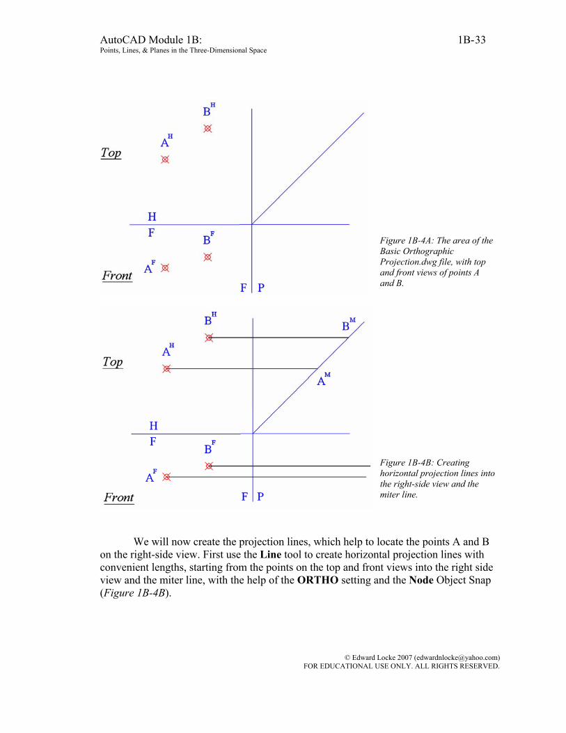
Figure 1B-4A: The area of the Basic Orthographic Projection.dwg file, with top and front views of points A and B.
Figure 1B-4B: Creating horizontal projection lines into the right-side view and the miter line.
We will now create the projection lines, which help to locate the points A and B
on the right-side view. First use the Line tool to create horizontal projection lines with convenient lengths, starting from the points on the top and front views into the right side view and the miter line, with the help of the ORTHO setting and the Node Object Snap (Figure 1B-4B).
© Edward Locke 2007 ([email protected]) FOR EDUCATIONAL USE ONLY. ALL RIGHTS RESERVED.
AutoCAD Module 1B: 1B- Points, Lines, & Planes in the Three-Dimensional Space
34
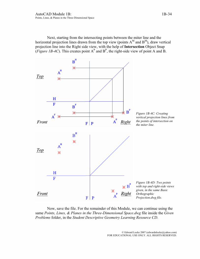
Next, starting from the intersecting points between the miter line and the horizontal projection lines drawn from the top view (points AM and BM), draw vertical projection line into the Right side view, with the help of Intersection Object Snap (Figure 1B-4C). This creates point AP and BP, the right-side view of point A and B.
Figure 1B-4C: Creating vertical projection lines from the points of intersection on the miter line.
Figure 1B-4D: Two points with top and right-side views given, in the same Basic Orthographic Projection.dwg file.
Now, save the file. For the remainder of this Module, we can continue using the
same Points, Lines, & Planes in the Three-Dimensional Space.dwg file inside the Given Problems folder, in the Student Descriptive Geometry Learning Resource CD.
© Edward Locke 2007 ([email protected]) FOR EDUCATIONAL USE ONLY. ALL RIGHTS RESERVED.
AutoCAD Module 1B: 1B- Points, Lines, & Planes in the Three-Dimensional Space
35
Section 5 Drawing a Missing View with Top and Right Side Views Given
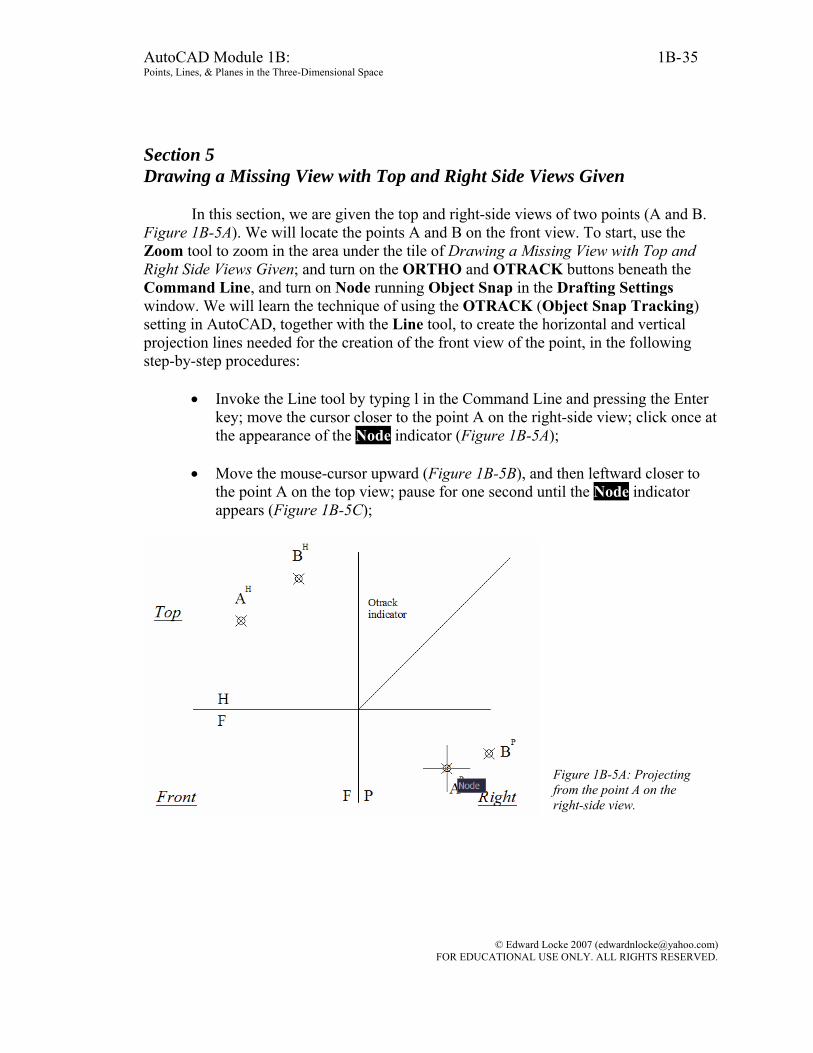
In this section, we are given the top and right-side views of two points (A and B. Figure 1B-5A). We will locate the points A and B on the front view. To start, use the Zoom tool to zoom in the area under the tile of Drawing a Missing View with Top and Right Side Views Given; and turn on the ORTHO and OTRACK buttons beneath the Command Line, and turn on Node running Object Snap in the Drafting Settings window. We will learn the technique of using the OTRACK (Object Snap Tracking) setting in AutoCAD, together with the Line tool, to create the horizontal and vertical projection lines needed for the creation of the front view of the point, in the following step-by-step procedures:
• Invoke the Line tool by typing l in the Command Line and pressing the Enter
key; move the cursor closer to the point A on the right-side view; click once at the appearance of the Node indicator (Figure 1B-5A);
• Move the mouse-cursor upward (Figure 1B-5B), and then leftward closer to
the point A on the top view; pause for one second until the Node indicator appears (Figure 1B-5C);
Figure 1B-5A: Projecting from the point A on the right-side view.
© Edward Locke 2007 ([email protected]) FOR EDUCATIONAL USE ONLY. ALL RIGHTS RESERVED.

AutoCAD Module 1B: 1B- Points, Lines, & Planes in the Three-Dimensional Space
36
Figure 1B-5B: Moving the mouse-cursor upward.
Figure 1B-5C: Picking up the Node Object Snap from the point B on the top view.
© Edward Locke 2007 ([email protected]) FOR EDUCATIONAL USE ONLY. ALL RIGHTS RESERVED.
AutoCAD Module 1B: 1B- Points, Lines, & Planes in the Three-Dimensional Space
37
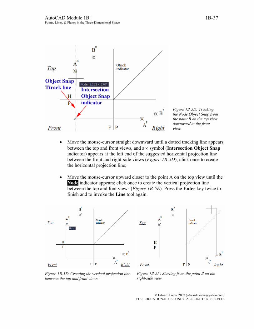
Figure 1B-5D: Tracking the Node Object Snap from the point B on the top view downward to the front view.
• Move the mouse-cursor straight downward until a dotted tracking line appears between the top and front views, and a × symbol (Intersection Object Snap indicator) appears at the left end of the suggested horizontal projection line between the front and right-side views (Figure 1B-5D); click once to create the horizontal projection line;
• Move the mouse-cursor upward closer to the point A on the top view until the
Node indicator appears; click once to create the vertical projection line between the top and font views (Figure 1B-5E). Press the Enter key twice to finish and to invoke the Line tool again.
Figure 1B-5E: Creating the vertical projection line between the top and front views.
Figure 1B-5F: Starting from the point B on the right-side view.
© Edward Locke 2007 ([email protected]) FOR EDUCATIONAL USE ONLY. ALL RIGHTS RESERVED.

AutoCAD Module 1B: 1B- Points, Lines, & Planes in the Three-Dimensional Space
38
Figure 1B-5G: Picking up the Node Object Snap from the point B on the top view.
Figure 1B-5H: Tracking the Node Object Snap of the point B on the top view, downward to the front view to create the horizontal projection line between the top and front views.
The projection line for the point B can be created in similar procedures (Figure
1B-5F, Figure 1B-5G and Figure 1B-5H). If the Object Snap Tracking method is too difficult to use, then another way to
create the orthographic projection lines is to draw horizontal and vertical projection lines starting from the points A and B on the top and right-side views into the front view, with any convenient lengths that are a little bit beyond their points of intersection (Figure 1B-5K); then use the Trim tool to cut off the excessive segments of the projection lines (Figure 1B-5L and Figure 1B-5M).
Figure 1B-5J: Creating the horizontal and vertical projection lines for point B.
Figure 1B-5K: Creating horizontal and vertical projection lines beyond their points of intersection.
© Edward Locke 2007 ([email protected]) FOR EDUCATIONAL USE ONLY. ALL RIGHTS RESERVED.

AutoCAD Module 1B: 1B- Points, Lines, & Planes in the Three-Dimensional Space
39
Figure 1B-5L: Selecting projection lines for trimming. Figure 1B-5M: Trimming off the excessive segments
f the vertical and horizontal projection lines.
Instead of using the Trim tool, the “click-drag-click” method can be used to bring the ends of the vertical and horizontal projection lines to their point of intersection (Figure 1B-5N), with the flowing step-by-step procedures:
• Click-select the line (Figure 1B-5N, top-left); • Click-select the grip, which turns red (Figure 1B-5N, top-right);
• Move the mouse-cursor closer to the point of intersection between the vertical
line and the 45° miter line; and click once at the appearance of the × symbol (Intersection Object Snap indicator. Figure 1B-5N, bottom-left);
• The end of the vertical line is brought to the point of intersection between the
vertical line and the 45° miter line (Figure 1B-5N, bottom-right).
© Edward Locke 2007 ([email protected]) FOR EDUCATIONAL USE ONLY. ALL RIGHTS RESERVED.

AutoCAD Module 1B: 1B- Points, Lines, & Planes in the Three-Dimensional Space
40
Figure 1B-5N: The “click-drag-click” method. Selecting the line (top-left); selecting the grip (top-right); moving the mouse-cursor closer to the point of intersection between and clicking once at the appearance of the × symbol (bottom-left); the end of the vertical line brought to the point of intersection (bottom-right).
Figure 1B-5P: The “perfect rectangles.”
© Edward Locke 2007 ([email protected]) FOR EDUCATIONAL USE ONLY. ALL RIGHTS RESERVED.
AutoCAD Module 1B: 1B- Points, Lines, & Planes in the Three-Dimensional Space
41
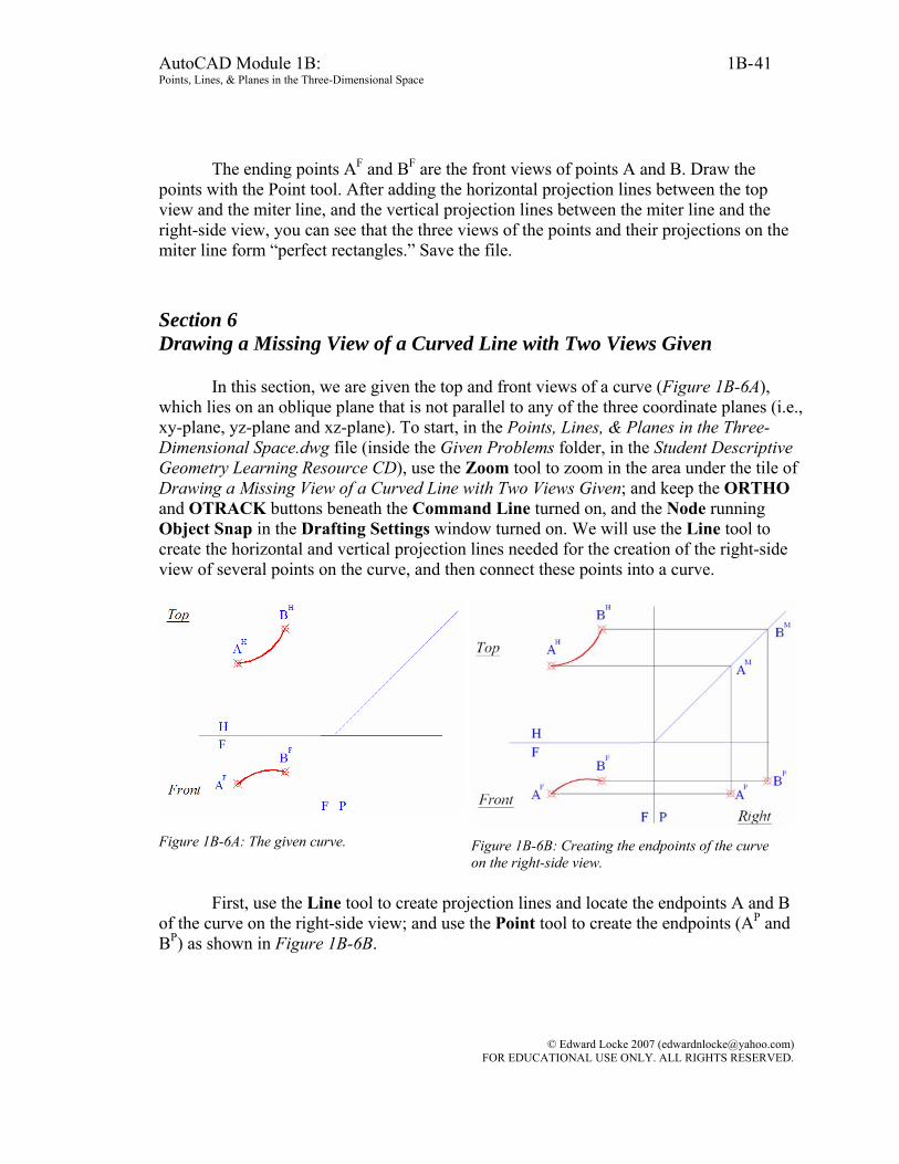
The ending points AF and BF are the front views of points A and B. Draw the points with the Point tool. After adding the horizontal projection lines between the top view and the miter line, and the vertical projection lines between the miter line and the right-side view, you can see that the three views of the points and their projections on the miter line form “perfect rectangles.” Save the file. Section 6 Drawing a Missing View of a Curved Line with Two Views Given
In this section, we are given the top and front views of a curve (Figure 1B-6A), which lies on an oblique plane that is not parallel to any of the three coordinate planes (i.e., xy-plane, yz-plane and xz-plane). To start, in the Points, Lines, & Planes in the Three-Dimensional Space.dwg file (inside the Given Problems folder, in the Student Descriptive Geometry Learning Resource CD), use the Zoom tool to zoom in the area under the tile of Drawing a Missing View of a Curved Line with Two Views Given; and keep the ORTHO and OTRACK buttons beneath the Command Line turned on, and the Node running Object Snap in the Drafting Settings window turned on. We will use the Line tool to create the horizontal and vertical projection lines needed for the creation of the right-side view of several points on the curve, and then connect these points into a curve.
Figure 1B-6A: The given curve. Figure 1B-6B: Creating the endpoints of the curve on the right-side view.
First, use the Line tool to create projection lines and locate the endpoints A and B
of the curve on the right-side view; and use the Point tool to create the endpoints (AP and BP) as shown in Figure 1B-6B.
© Edward Locke 2007 ([email protected]) FOR EDUCATIONAL USE ONLY. ALL RIGHTS RESERVED.
AutoCAD Module 1B: 1B- Points, Lines, & Planes in the Three-Dimensional Space
42
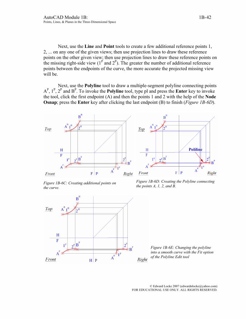
Next, use the Line and Point tools to create a few additional reference points 1, 2, ... on any one of the given views; then use projection lines to draw these reference points on the other given view; then use projection lines to draw these reference points on the missing right-side view (1P and 2P). The greater the number of additional reference points between the endpoints of the curve, the more accurate the projected missing view will be.
Next, use the Polyline tool to draw a multiple-segment polyline connecting points AP, 1P, 2P and BP. To invoke the Polyline tool, type pl and press the Enter key to invoke the tool, click the first endpoint (A) and then the points 1 and 2 with the help of the Node Osnap; press the Enter key after clicking the last endpoint (B) to finish (Figure 1B-6D).
Figure 1B-6C: Creating additional points on the curve.
Figure 1B-6D: Creating the Polyline connecting the points A, 1, 2, and B.
Figure 1B-6E: Changing the polyline into a smooth curve with the Fit option of the Polyline Edit tool
© Edward Locke 2007 ([email protected]) FOR EDUCATIONAL USE ONLY. ALL RIGHTS RESERVED.
AutoCAD Module 1B: 1B- Points, Lines, & Planes in the Three-Dimensional Space
43
Next use the Polyline Edit tool with Fit option to turn the polyline into a curved line (Figure 1B-6E): Command: pe [Type pe and press the Enter key to invoke the Polyline Edit tool] PEDIT Select polyline or [Multiple]: [Click on the polyline] Enter an option [Close/Join/Width/Edit vertex/Fit/Spline/Decurve/Ltype gen/Undo]: f [Type f to select the Fit option and press the Enter key to finish] Enter an option [Close/Join/Width/Edit vertex/Fit/Spline/Decurve/Ltype gen/Undo]: *Cancel* [Press the Enter key to exit the Polyline Edit tool]
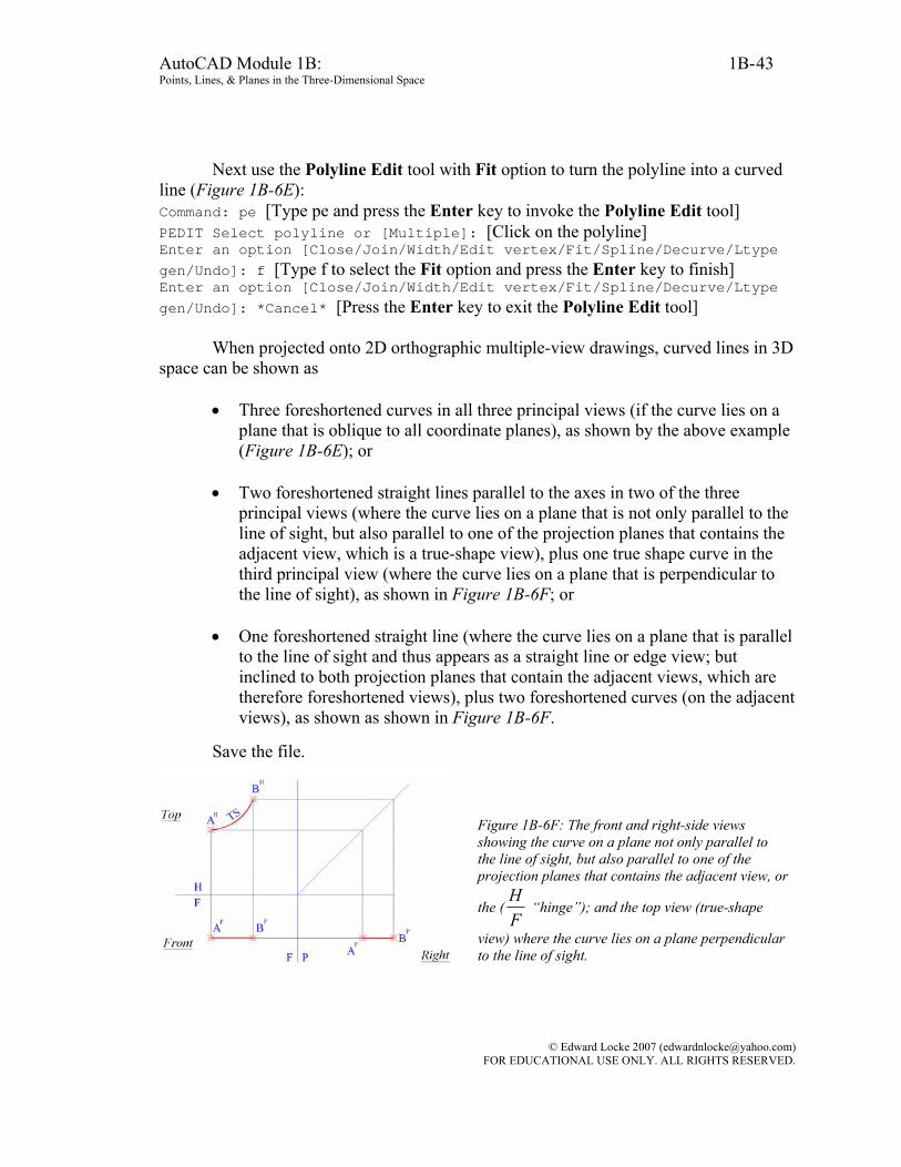
When projected onto 2D orthographic multiple-view drawings, curved lines in 3D space can be shown as
• Three foreshortened curves in all three principal views (if the curve lies on a
plane that is oblique to all coordinate planes), as shown by the above example (Figure 1B-6E); or
• Two foreshortened straight lines parallel to the axes in two of the three
principal views (where the curve lies on a plane that is not only parallel to the line of sight, but also parallel to one of the projection planes that contains the adjacent view, which is a true-shape view), plus one true shape curve in the third principal view (where the curve lies on a plane that is perpendicular to the line of sight), as shown in Figure 1B-6F; or
• One foreshortened straight line (where the curve lies on a plane that is parallel
to the line of sight and thus appears as a straight line or edge view; but inclined to both projection planes that contain the adjacent views, which are therefore foreshortened views), plus two foreshortened curves (on the adjacent views), as shown as shown in Figure 1B-6F.
Save the file.
Figure 1B-6F: The front and right-side views showing the curve on a plane not only parallel to the line of sight, but also parallel to one of the projection planes that contains the adjacent view, or
the (FH
“hinge”); and the top view (true-shape
view) where the curve lies on a plane perpendicular to the line of sight.
© Edward Locke 2007 ([email protected]) FOR EDUCATIONAL USE ONLY. ALL RIGHTS RESERVED.

AutoCAD Module 1B: 1B- Points, Lines, & Planes in the Three-Dimensional Space
44
Figure 1B-6G: The plane containing the front view of the curve inclined to both adjacent top and right-side views, and appearing as a straight line or edge view (the straight line edge view not parallel to
theFH
and PF ”hinges” ). The foreshortened
curves on the top and right-side views, on the planes not parallel to the horizontal and profile planes.
Section 7 Drawing a Missing View of a Plane with Two Views Given
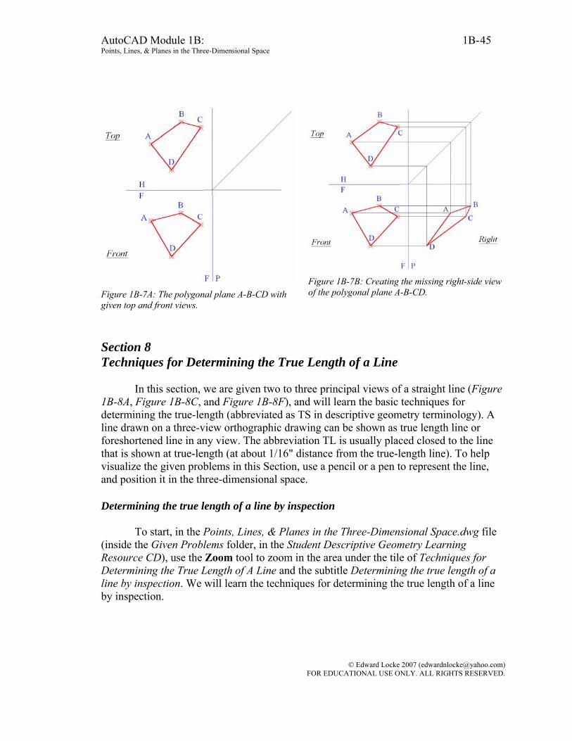
In this section, we are given the top and right-side views of a polygonal plane A-B-CD (Figure 1B-7A). We will locate the points A and B on the front view. To start, in the Points, Lines, & Planes in the Three-Dimensional Space.dwg file (inside the Given Problems folder, in the Student Descriptive Geometry Learning Resource CD), use the Zoom tool to zoom in the area under the tile of Drawing a Missing View of a Plane with Two Views Given; and keep the ORTHO and OTRACK buttons beneath the Command Line turned on, and the Node running Object Snap in the Drafting Settings window turned on. We will use the Line tool to create the horizontal and vertical projection lines needed for the creation of the right-side view of the corner points of the polygonal plane, and then connect these points into a polygonal plane.
The key to drawing a missing view of a polygonal plane with two given views is to draw the missing views of the corner points of the plane, and to connect these points with the Polyline tool with the help of the Endpoints Object Snaps (Figure 1B-7B). Save the file.
© Edward Locke 2007 ([email protected]) FOR EDUCATIONAL USE ONLY. ALL RIGHTS RESERVED.
AutoCAD Module 1B: 1B- Points, Lines, & Planes in the Three-Dimensional Space
45
Figure 1B-7A: The polygonal plane A-B-CD with given top and front views.
Figure 1B-7B: Creating the missing right-side view of the polygonal plane A-B-CD.
Section 8 Techniques for Determining the True Length of a Line
In this section, we are given two to three principal views of a straight line (Figure 1B-8A, Figure 1B-8C, and Figure 1B-8F), and will learn the basic techniques for determining the true-length (abbreviated as TS in descriptive geometry terminology). A line drawn on a three-view orthographic drawing can be shown as true length line or foreshortened line in any view. The abbreviation TL is usually placed closed to the line that is shown at true-length (at about 1/16" distance from the true-length line). To help visualize the given problems in this Section, use a pencil or a pen to represent the line, and position it in the three-dimensional space. Determining the true length of a line by inspection
To start, in the Points, Lines, & Planes in the Three-Dimensional Space.dwg file
(inside the Given Problems folder, in the Student Descriptive Geometry Learning Resource CD), use the Zoom tool to zoom in the area under the tile of Techniques for Determining the True Length of A Line and the subtitle Determining the true length of a line by inspection. We will learn the techniques for determining the true length of a line by inspection.
© Edward Locke 2007 ([email protected]) FOR EDUCATIONAL USE ONLY. ALL RIGHTS RESERVED.
AutoCAD Module 1B: 1B- Points, Lines, & Planes in the Three-Dimensional Space
46
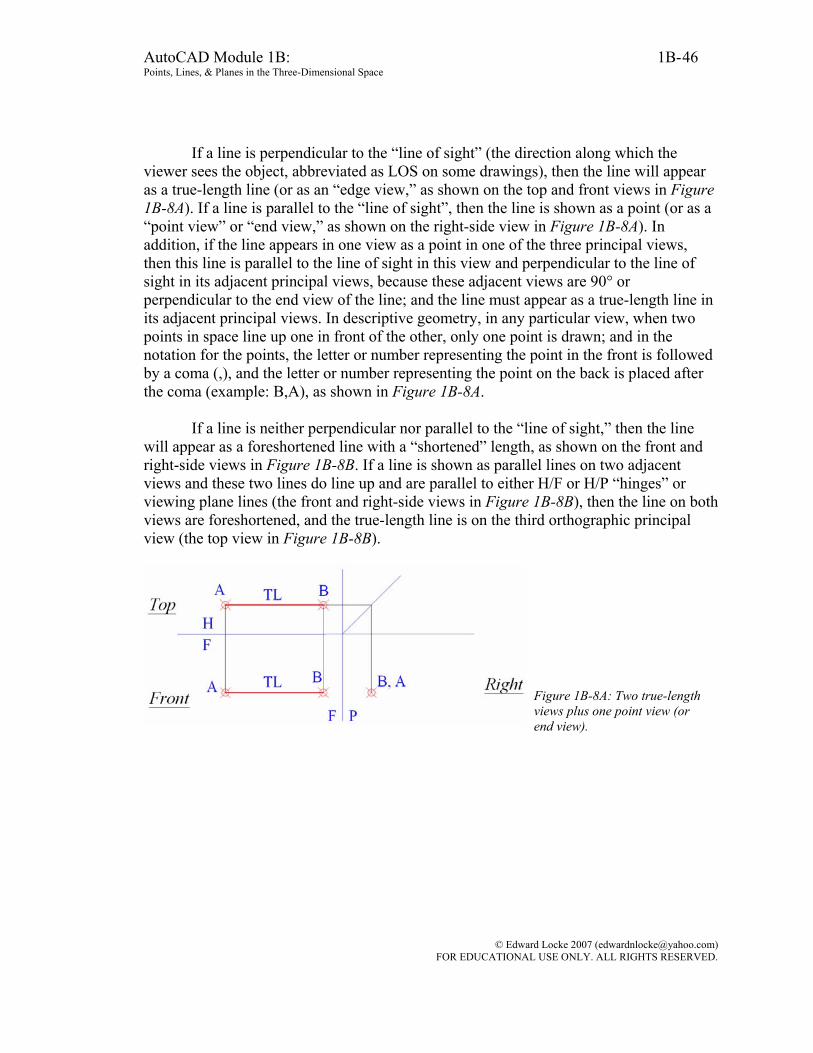
If a line is perpendicular to the “line of sight” (the direction along which the viewer sees the object, abbreviated as LOS on some drawings), then the line will appear as a true-length line (or as an “edge view,” as shown on the top and front views in Figure 1B-8A). If a line is parallel to the “line of sight”, then the line is shown as a point (or as a “point view” or “end view,” as shown on the right-side view in Figure 1B-8A). In addition, if the line appears in one view as a point in one of the three principal views, then this line is parallel to the line of sight in this view and perpendicular to the line of sight in its adjacent principal views, because these adjacent views are 90° or perpendicular to the end view of the line; and the line must appear as a true-length line in its adjacent principal views. In descriptive geometry, in any particular view, when two points in space line up one in front of the other, only one point is drawn; and in the notation for the points, the letter or number representing the point in the front is followed by a coma (,), and the letter or number representing the point on the back is placed after the coma (example: B,A), as shown in Figure 1B-8A.
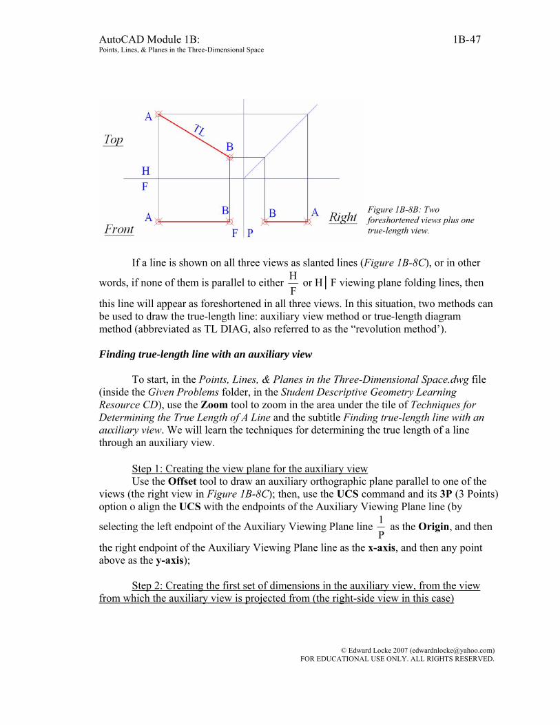
If a line is neither perpendicular nor parallel to the “line of sight,” then the line will appear as a foreshortened line with a “shortened” length, as shown on the front and right-side views in Figure 1B-8B. If a line is shown as parallel lines on two adjacent views and these two lines do line up and are parallel to either H/F or H/P “hinges” or viewing plane lines (the front and right-side views in Figure 1B-8B), then the line on both views are foreshortened, and the true-length line is on the third orthographic principal view (the top view in Figure 1B-8B).
Figure 1B-8A: Two true-length views plus one point view (or end view).
© Edward Locke 2007 ([email protected]) FOR EDUCATIONAL USE ONLY. ALL RIGHTS RESERVED.
AutoCAD Module 1B: 1B- Points, Lines, & Planes in the Three-Dimensional Space
47
Figure 1B-8B: Two foreshortened views plus one true-length view.
If a line is shown on all three views as slanted lines (Figure 1B-8C), or in other
words, if none of them is parallel to either FH or H│F viewing plane folding lines, then
this line will appear as foreshortened in all three views. In this situation, two methods can be used to draw the true-length line: auxiliary view method or true-length diagram method (abbreviated as TL DIAG, also referred to as the “revolution method’). Finding true-length line with an auxiliary view
To start, in the Points, Lines, & Planes in the Three-Dimensional Space.dwg file (inside the Given Problems folder, in the Student Descriptive Geometry Learning Resource CD), use the Zoom tool to zoom in the area under the tile of Techniques for Determining the True Length of A Line and the subtitle Finding true-length line with an auxiliary view. We will learn the techniques for determining the true length of a line through an auxiliary view.
Step 1: Creating the view plane for the auxiliary view Use the Offset tool to draw an auxiliary orthographic plane parallel to one of the
views (the right view in Figure 1B-8C); then, use the UCS command and its 3P (3 Points) option o align the UCS with the endpoints of the Auxiliary Viewing Plane line (by
selecting the left endpoint of the Auxiliary Viewing Plane line P1 as the Origin, and then
the right endpoint of the Auxiliary Viewing Plane line as the x-axis, and then any point above as the y-axis);
Step 2: Creating the first set of dimensions in the auxiliary view, from the view
from which the auxiliary view is projected from (the right-side view in this case)
© Edward Locke 2007 ([email protected]) FOR EDUCATIONAL USE ONLY. ALL RIGHTS RESERVED.
AutoCAD Module 1B: 1B- Points, Lines, & Planes in the Three-Dimensional Space
48
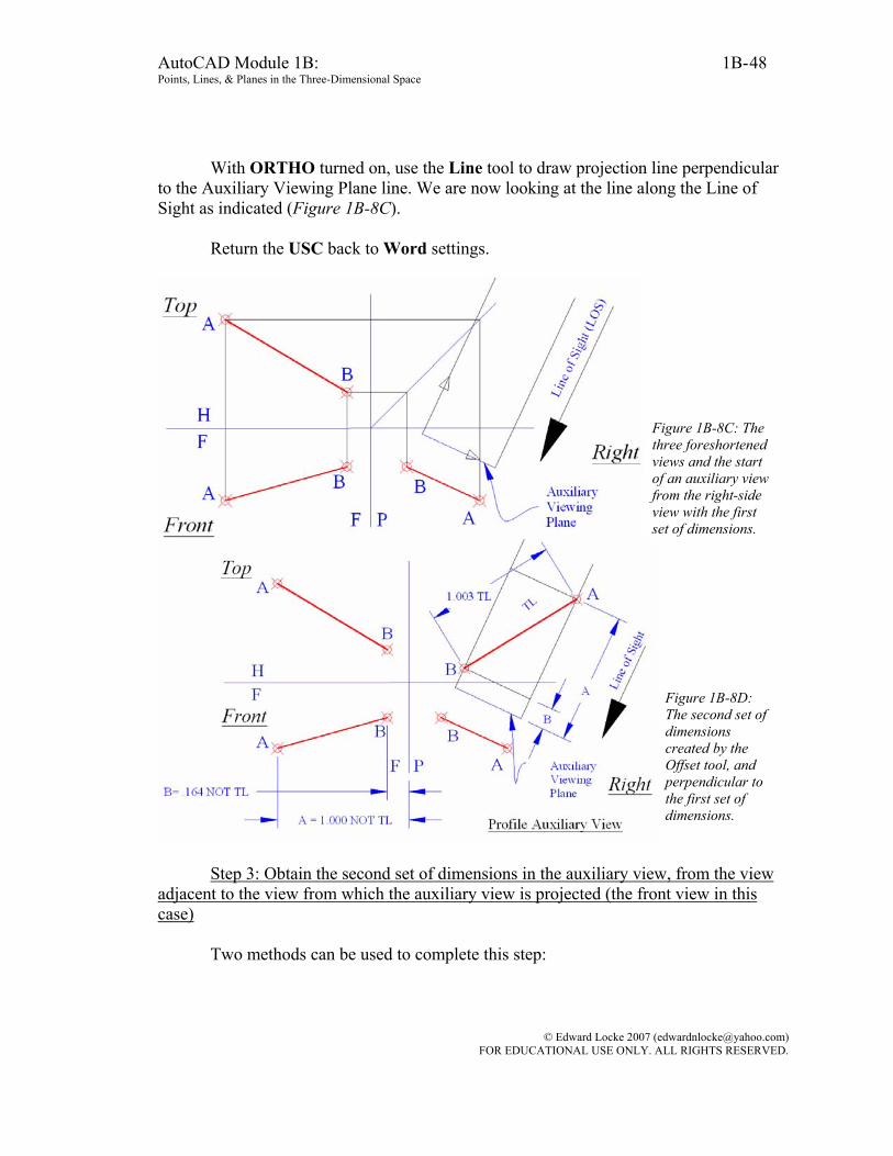
With ORTHO turned on, use the Line tool to draw projection line perpendicular to the Auxiliary Viewing Plane line. We are now looking at the line along the Line of Sight as indicated (Figure 1B-8C).
Return the USC back to Word settings.
Figure 1B-8C: The three foreshortened views and the start of an auxiliary view from the right-side view with the first set of dimensions.
Figure 1B-8D: The second set of dimensions created by the Offset tool, and perpendicular to the first set of dimensions.
Step 3: Obtain the second set of dimensions in the auxiliary view, from the view
adjacent to the view from which the auxiliary view is projected (the front view in this case)
Two methods can be used to complete this step:
© Edward Locke 2007 ([email protected]) FOR EDUCATIONAL USE ONLY. ALL RIGHTS RESERVED.

AutoCAD Module 1B: 1B- Points, Lines, & Planes in the Three-Dimensional Space
49
The first method (with Linear Dimension and Offset tools): Use the Linear Dimension tool to measure the distances from points A and B to the F│P viewing plane line (the linear dimensions are A = 1.000 and B = 0.164 respectively; the notes NOT TL are added here to indicate that the dimensions do not indicate the true-length of the line, but rather the measured linear distances on a view plane, onto which the endpoints of the foreshortened line are projected). Next, use the Offset tool to set off the same distances
on the auxiliary view, from the Auxiliary Viewing Plane line P1 . This gives the points of
intersection between the first set of dimensional construction lines, and the second set of dimensional construction lines perpendicular to the first set of dimensional construction lines, which are created with the Offset tool (Figure 1B-8D).
Figure 1B-8E: Setting the center of the first construction circle at the point o.
© Edward Locke 2007 ([email protected]) FOR EDUCATIONAL USE ONLY. ALL RIGHTS RESERVED.
AutoCAD Module 1B: 1B- Points, Lines, & Planes in the Three-Dimensional Space
50
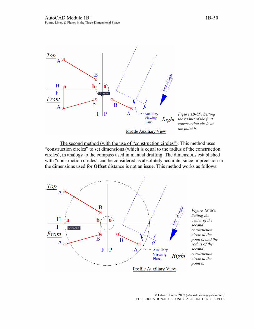
Figure 1B-8F: Setting the radius of the first construction circle at the point b.
The second method (with the use of “construction circles”): This method uses
“construction circles” to set dimensions (which is equal to the radius of the construction circles), in analogy to the compass used in manual drafting. The dimensions established with “construction circles” can be considered as absolutely accurate, since imprecision in the dimensions used for Offset distance is not an issue. This method works as follows:
Figure 1B-8G: Setting the center of the second construction circle at the point o, and the radius of the second construction circle at the point a.
© Edward Locke 2007 ([email protected]) FOR EDUCATIONAL USE ONLY. ALL RIGHTS RESERVED.

AutoCAD Module 1B: 1B- Points, Lines, & Planes in the Three-Dimensional Space
51
Figure 1B-8H: Selecting the two cons-truction circles and their common center.
Use the Line tool to draw vertical construction lines from the points A and B on
the front view upward and slightly beyond the horizontal FH viewing plane line, giving
the points of intersection a and b. Next, use the Circle tool to create two construction
circles, both centered at the point o (point of intersection between the FH viewing plane
line and the PF viewing plane line), with the radius set at the point a and b respectively: Command: c [Type c and press the Enter key to invoke the Circle tool] (Figure 1B-8E) CIRCLE Specify center point for circle or [3P/2P/Ttr (tan tan radius)]: [Click once at the point o when the Intersection Object Snap indicator symbol appears, to set the center of the smaller construction circle, with a radius equal to
the distance between the point B and the FH viewing plane line] (Figure 1B-8F)
Specify radius of circle or [Diameter] <1.000>: [Click once at the point a when the Intersection Object Snap indicator symbol appears, to set the radius of the smaller construction circle, with a radius equal to the distance between the point B and
the FH viewing plane line. Press the Enter key to invoke the Circle tool again]
Command: CIRCLE Specify center point for circle or [3P/2P/Ttr (tan tan
© Edward Locke 2007 ([email protected]) FOR EDUCATIONAL USE ONLY. ALL RIGHTS RESERVED.
AutoCAD Module 1B: 1B- Points, Lines, & Planes in the Three-Dimensional Space
52
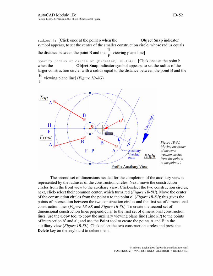
radius)]: [Click once at the point o when the Intersection Object Snap indicator symbol appears, to set the center of the smaller construction circle, whose radius equals
the distance between the point B and the FH viewing plane line]
Specify radius of circle or [Diameter] <0.164>: [Click once at the point b when the Intersection Object Snap indicator symbol appears, to set the radius of the larger construction circle, with a radius equal to the distance between the point B and the
FH viewing plane line] (Figure 1B-8G)
Figure 1B-8J: Moving the center of the cons-truction circles from the point o to the point o’.
The second set of dimensions needed for the completion of the auxiliary view is
represented by the radiuses of the construction circles. Next, move the construction circles from the front view to the auxiliary view. Click-select the two construction circles; next, click-select their common center, which turns red (Figure 1B-8H). Move the center of the construction circles from the point o to the point o’ (Figure 1B-8J); this gives the points of intersection between the two construction circles and the first set of dimensional construction lines (Figure 1B-8K and Figure 1B-8L). To create the second set of dimensional construction lines perpendicular to the first set of dimensional construction lines, use the Copy tool to copy the auxiliary viewing plane line (Line1/P) to the points of intersection b’ and a’; and use the Point tool to create the points A and B in the auxiliary view (Figure 1B-8L). Click-select the two construction circles and press the Delete key on the keyboard to delete them.
© Edward Locke 2007 ([email protected]) FOR EDUCATIONAL USE ONLY. ALL RIGHTS RESERVED.

AutoCAD Module 1B: 1B- Points, Lines, & Planes in the Three-Dimensional Space
53
Figure 1B-8K: The points of intersection between the two construction circles and the first set of dimensional construction lines.
Figure 1B-8L: Using the Copy tool to copy the auxiliary viewing plane line (Line1/P) to the points of intersection b’ and a’; and using the Point tool to create the points A and B in the auxiliary view.
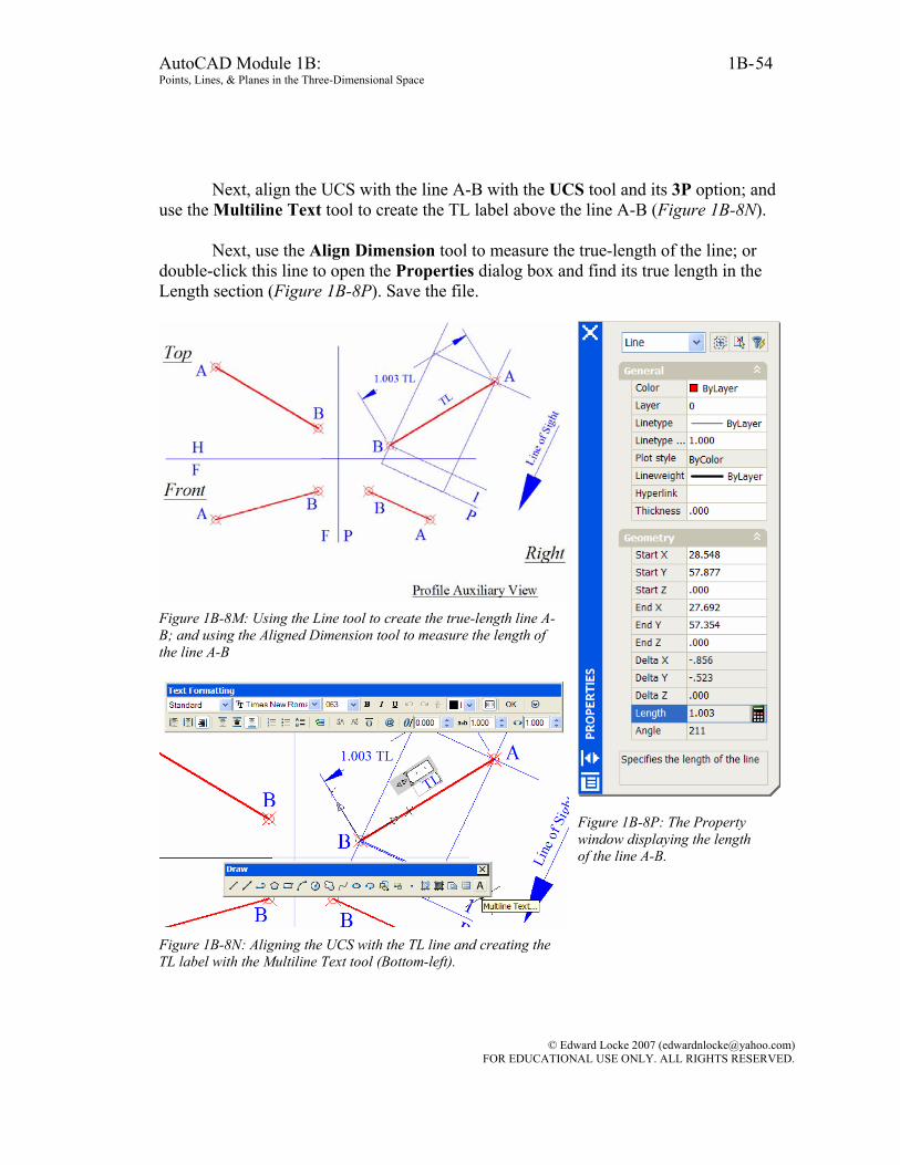
Step 4: Creating the true-length line A-B, and determining its true length Points A and B are now created on the auxiliary view. Next, use the Line tool to
draw the true-length line connecting points A and B in the auxiliary view. Use the Aligned Dimension tool to measure the true length of the line A-B (Figure 1B-8M).
© Edward Locke 2007 ([email protected]) FOR EDUCATIONAL USE ONLY. ALL RIGHTS RESERVED.
AutoCAD Module 1B: 1B- Points, Lines, & Planes in the Three-Dimensional Space
54
Next, align the UCS with the line A-B with the UCS tool and its 3P option; and
use the Multiline Text tool to create the TL label above the line A-B (Figure 1B-8N). Next, use the Align Dimension tool to measure the true-length of the line; or
double-click this line to open the Properties dialog box and find its true length in the Length section (Figure 1B-8P). Save the file.
Figure 1B-8M: Using the Line tool to create the true-length line A-B; and using the Aligned Dimension tool to measure the length of the line A-B
Figure 1B-8N: Aligning the UCS with the TL line and creating the TL label with the Multiline Text tool (Bottom-left).
Figure 1B-8P: The Property window displaying the length of the line A-B.
© Edward Locke 2007 ([email protected]) FOR EDUCATIONAL USE ONLY. ALL RIGHTS RESERVED.
AutoCAD Module 1B: 1B- Points, Lines, & Planes in the Three-Dimensional Space
55
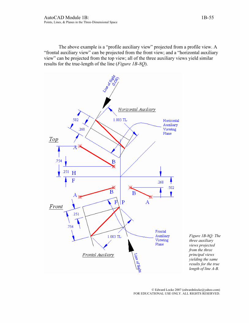
The above example is a “profile auxiliary view” projected from a profile view. A “frontal auxiliary view” can be projected from the front view; and a “horizontal auxiliary view” can be projected from the top view; all of the three auxiliary views yield similar results for the true-length of the line (Figure 1B-8Q).
Figure 1B-8Q: The three auxiliary views projected from the three principal views yielding the same results for the true length of line A-B.
© Edward Locke 2007 ([email protected]) FOR EDUCATIONAL USE ONLY. ALL RIGHTS RESERVED.

AutoCAD Module 1B: 1B- Points, Lines, & Planes in the Three-Dimensional Space
56
In the real world of engineering design today, more and more engineers will design most of parts in the beginning as a 3D model and then create orthographic drawings based on the 3D model. In AutoCAD, the true length of an oblique line created in 3D can be determined with the List, Distance, Identification, or Properties tool; and an auxiliary view of the line can be generated in the Layout Space by these steps: First align the USC in the Model Space with the line; then go to the Layout Space; use the Solview command with Auxiliary/UCS option to create an auxiliary view; then use the Linear Dimension tool to place the true-length dimension of the line. Details will be available in Module 9 (Part Seven-Solving Descriptive Geometry Problems in AutoCAD 3D Environment). Finding the true-length line with a true-length diagram
To start, in the Points, Lines, & Planes in the Three-Dimensional Space.dwg file (inside the Given Problems folder, in the Student Descriptive Geometry Learning Resource CD), use the Zoom tool to zoom in the area under the tile of Techniques for Determining the True Length of A Line and the subtitle Finding the true-length line with a true-length diagram. We will learn the techniques for determining the true length of a line by the true-length diagram method.
The true-length diagram (abbreviated as TL DIAG) is a method to graphically find the true-length line when the line is foreshortened in the given principal views. This method is also called the “revolution method.”
Figure 1B-8R: The given foreshortened line A-B on the top and front views.
Figure 1B-8S: Rotating line A-B on the top view to a plane parallel to the frontal plane, with the point A fixed and the point B rotated; and projecting the point BBr from the top view to the front view.
Two adjacent views are needed for using the true-length diagram or revolution
method to find the true-length of a line. As shown in Figure 1B-8R, line A-B is shown foreshortened in both top and front views. If we can rotate line A-B in either view so that
© Edward Locke 2007 ([email protected]) FOR EDUCATIONAL USE ONLY. ALL RIGHTS RESERVED.
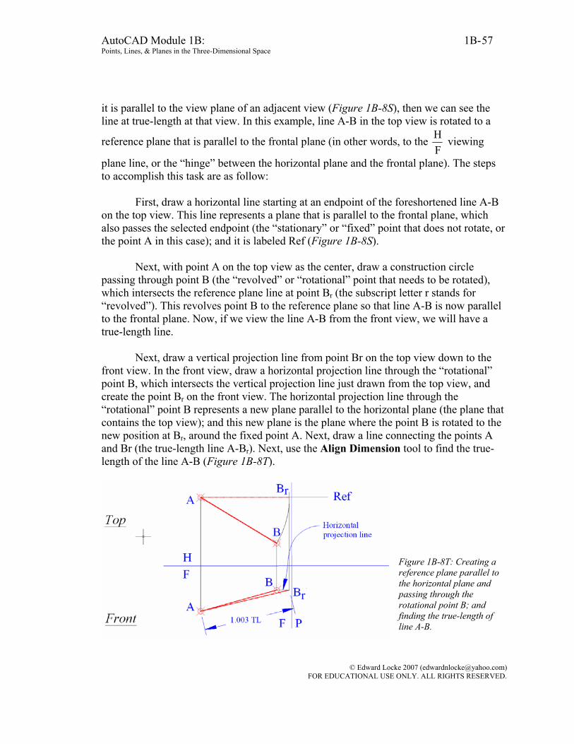
AutoCAD Module 1B: 1B- Points, Lines, & Planes in the Three-Dimensional Space
57
it is parallel to the view plane of an adjacent view (Figure 1B-8S), then we can see the line at true-length at that view. In this example, line A-B in the top view is rotated to a
reference plane that is parallel to the frontal plane (in other words, to the FH viewing
plane line, or the “hinge” between the horizontal plane and the frontal plane). The steps to accomplish this task are as follow:
First, draw a horizontal line starting at an endpoint of the foreshortened line A-B
on the top view. This line represents a plane that is parallel to the frontal plane, which also passes the selected endpoint (the “stationary” or “fixed” point that does not rotate, or the point A in this case); and it is labeled Ref (Figure 1B-8S).
Next, with point A on the top view as the center, draw a construction circle
passing through point B (the “revolved” or “rotational” point that needs to be rotated), which intersects the reference plane line at point Br (the subscript letter r stands for “revolved”). This revolves point B to the reference plane so that line A-B is now parallel to the frontal plane. Now, if we view the line A-B from the front view, we will have a true-length line.
Next, draw a vertical projection line from point Br on the top view down to the
front view. In the front view, draw a horizontal projection line through the “rotational” point B, which intersects the vertical projection line just drawn from the top view, and create the point Br on the front view. The horizontal projection line through the “rotational” point B represents a new plane parallel to the horizontal plane (the plane that contains the top view); and this new plane is the plane where the point B is rotated to the new position at Br, around the fixed point A. Next, draw a line connecting the points A and Br (the true-length line A-Br). Next, use the Align Dimension tool to find the true-length of the line A-B (Figure 1B-8T).
Figure 1B-8T: Creating a reference plane parallel to the horizontal plane and passing through the rotational point B; and finding the true-length of line A-B.
© Edward Locke 2007 ([email protected]) FOR EDUCATIONAL USE ONLY. ALL RIGHTS RESERVED.
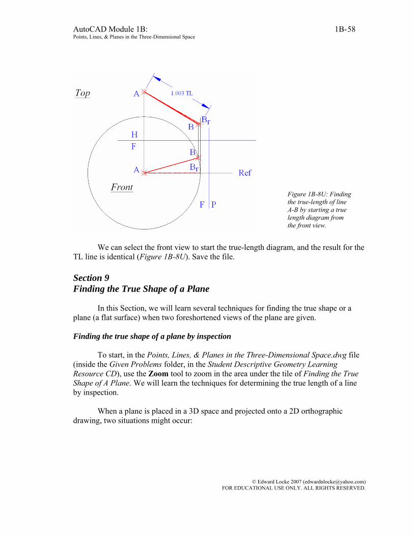
AutoCAD Module 1B: 1B- Points, Lines, & Planes in the Three-Dimensional Space
58
Figure 1B-8U: Finding the true-length of line A-B by starting a true length diagram from the front view.
We can select the front view to start the true-length diagram, and the result for the
TL line is identical (Figure 1B-8U). Save the file. Section 9 Finding the True Shape of a Plane
In this Section, we will learn several techniques for finding the true shape or a plane (a flat surface) when two foreshortened views of the plane are given. Finding the true shape of a plane by inspection
To start, in the Points, Lines, & Planes in the Three-Dimensional Space.dwg file (inside the Given Problems folder, in the Student Descriptive Geometry Learning Resource CD), use the Zoom tool to zoom in the area under the tile of Finding the True Shape of A Plane. We will learn the techniques for determining the true length of a line by inspection.
When a plane is placed in a 3D space and projected onto a 2D orthographic
drawing, two situations might occur:
© Edward Locke 2007 ([email protected]) FOR EDUCATIONAL USE ONLY. ALL RIGHTS RESERVED.
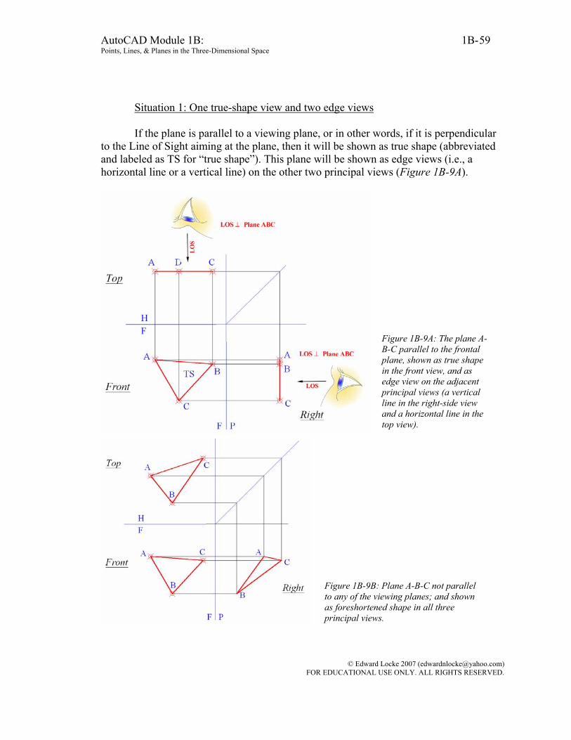
AutoCAD Module 1B: 1B- Points, Lines, & Planes in the Three-Dimensional Space
59
Situation 1: One true-shape view and two edge views If the plane is parallel to a viewing plane, or in other words, if it is perpendicular
to the Line of Sight aiming at the plane, then it will be shown as true shape (abbreviated and labeled as TS for “true shape”). This plane will be shown as edge views (i.e., a horizontal line or a vertical line) on the other two principal views (Figure 1B-9A).
Figure 1B-9A: The plane A-B-C parallel to the frontal plane, shown as true shape in the front view, and as edge view on the adjacent principal views (a vertical line in the right-side view and a horizontal line in the top view).
Figure 1B-9B: Plane A-B-C not parallel to any of the viewing planes; and shown as foreshortened shape in all three principal views.
© Edward Locke 2007 ([email protected]) FOR EDUCATIONAL USE ONLY. ALL RIGHTS RESERVED.

AutoCAD Module 1B: 1B- Points, Lines, & Planes in the Three-Dimensional Space
60
Situation 2: Three foreshortened views If the plane is not parallel to any of the three principal viewing planes (H, F and
P), or in other words, if it is not perpendicular to the Line of Sight viewing at any of these planes, then, none of its views will be an edge view; and it will be shown as foreshortened shapes in all three principal views. Primary and secondary auxiliary views are needed to obtain the true shape of the plane (Figure 1B-9B).
To find the true shape of the plane A-B-C, a primary auxiliary view is projected parallel to the plane from a selected foreshortened view so as to create an edge view of the plane (or in other words, to allow the plane to be projected from to appear as a straight line). The secondary auxiliary view is then projected perpendicular to this edge view to find the true shape of the plane. Read the following paragraphs for details. Finding the true shape of a plane with primary and secondary auxiliary views
In Figure 1B-9B, none of the three orthographic views of the plane A-B-C is in
true shape. In addition, since none of the edge is shown parallel to either F
H plane line or
PH plane line, none of the edge line is at true length. Therefore, there is no reference line to be used for the projection of the primary auxiliary view. We need to come up with such a true-length reference line first.
Since the plane contains an infinite number of lines, we can assume a true-length
reference line on the plane. We know that if a line on the horizontal plane (the plane
containing the top view) appears as parallel to the F
H plane line, then it will appear at
true-length on the frontal plane (the plane containing the front view). Therefore, with ORTHO on, first draw on the top view a horizontal line starting at point A and intersecting the edge line BC at point x. Any horizontal line within the plane on the top
view can be drawn, since it will be parallel to the F
H plane line. However, it is more
convenient to draw one passing through an existing corner point. Next, draw a projection line from point x down to the front view. This creates point x on the front view, Next, draw a line connecting the points A and x on the front view; this is the true-length reference line needed for the projection of the primary auxiliary view, to obtain the edge view (EV) of the plane A-B-C (Figure 1B-9C).
© Edward Locke 2007 ([email protected]) FOR EDUCATIONAL USE ONLY. ALL RIGHTS RESERVED.
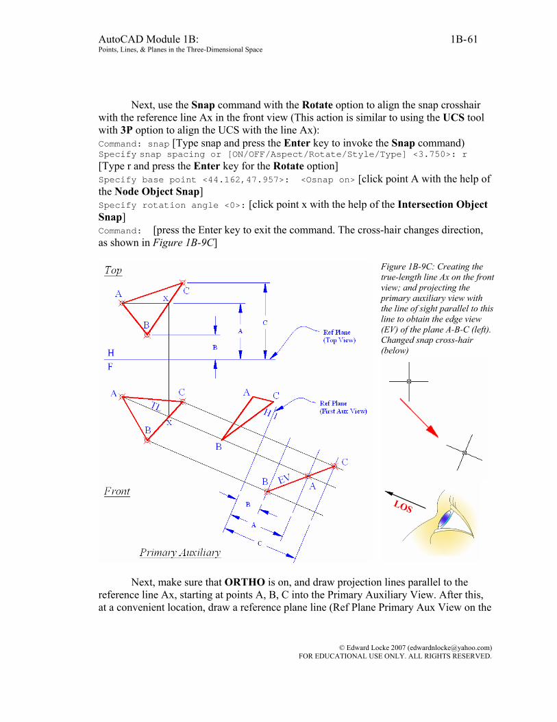
AutoCAD Module 1B: 1B- Points, Lines, & Planes in the Three-Dimensional Space
61
Next, use the Snap command with the Rotate option to align the snap crosshair with the reference line Ax in the front view (This action is similar to using the UCS tool with 3P option to align the UCS with the line Ax): Command: snap [Type snap and press the Enter key to invoke the Snap command) Specify snap spacing or [ON/OFF/Aspect/Rotate/Style/Type] <3.750>: r [Type r and press the Enter key for the Rotate option] Specify base point <44.162,47.957>: <Osnap on> [click point A with the help of the Node Object Snap] Specify rotation angle <0>: [click point x with the help of the Intersection Object Snap] Command: [press the Enter key to exit the command. The cross-hair changes direction, as shown in Figure 1B-9C]
Figure 1B-9C: Creating the true-length line Ax on the front view; and projecting the primary auxiliary view with the line of sight parallel to this line to obtain the edge view (EV) of the plane A-B-C (left). Changed snap cross-hair (below)
Next, make sure that ORTHO is on, and draw projection lines parallel to the reference line Ax, starting at points A, B, C into the Primary Auxiliary View. After this, at a convenient location, draw a reference plane line (Ref Plane Primary Aux View on the
© Edward Locke 2007 ([email protected]) FOR EDUCATIONAL USE ONLY. ALL RIGHTS RESERVED.
AutoCAD Module 1B: 1B- Points, Lines, & Planes in the Three-Dimensional Space
62
drawing, labeled as 1H ), which is perpendicular to the projection lines drawn in this step (Figure 1B-9C). Turn ORTHO off.
The basic steps to drawing any auxiliary view are: 1. To draw perpendicular projection lines from a true-length edge line on one
view so as to obtain the first set of dimensions, and 2. To borrow the second set of dimensions from an adjacent view. Since we project from the front view, we will obtain another set of dimensions
from the adjacent top view. Use the Linear Dimension or Distance tool to measure the projected distance on the reference plane A, B, C on the top view. Next, use the Offset tool to set off distances A, B, C from the reference plane line on the Primary Auxiliary View, as shown in Figure 1B-9C. These offset lines can be considered as additional reference planes which contain points A, B, and C respectively. If desired, instead of using the Linear Dimension and Offset tool method, the previously discussed “construction circle method” can be used to establish the second set of dimensions.
Next, identify the corner points A, B, C on the Primary Auxiliary View by
identifying the intersection of their projection line from the front view and the reference planes that contain them (For example: the point B is located at the point of intersection, between the projection line drawn from point B in the front view, and the plane that is at a distance B from the 1H Ref Plane line). Next use the Line or Polyline tool to draw a line connecting points A, B, and C, which is a straight line or an “edge view: for the plane A-B-C. The primary Auxiliary View is completed.
The Secondary Auxiliary View (Figure 1B-9D) will be projected from the Primary Auxiliary View, in a viewing plane parallel to the EV of the plane A-B-C on the Primary Auxiliary View, as follows:
First align the UCS or Snap to the edge line BAC on the Primary Auxiliary View,
and turn ORTHO on. Draw perpendicular projection lines from points A, B, C into the Secondary
Auxiliary View.
Next, draw the Ref Plane (Secondary Aux View) line parallel to and above the edge view line BAC.
Next, align the UCS to the reference line Ax on the front view; use the Linear Dimension tool to measure the projected distances between points A, B, C on the front
© Edward Locke 2007 ([email protected]) FOR EDUCATIONAL USE ONLY. ALL RIGHTS RESERVED.

AutoCAD Module 1B: 1B- Points, Lines, & Planes in the Three-Dimensional Space
63
view and the Ref Plane (First Aux View) 1F line as shown in Figure 1B-9D. Next, return the UCS to default World setting. Use the Offset tool to set off additional reference
plane lines at distance A, B, and C from the Ref Plane (Secondary Aux View) 12 line.
Figure 1B-9D: Creating the Secondary Auxiliary View to obtain the true shape of the plane A-B-C.
Next, identify the corner points A, B, C on the Secondary Auxiliary View by
identifying the intersection of their projection line from the Primary Auxiliary View and the reference planes that contain them.
Next, in the Secondary Auxiliary view, use the Line or Polyline tool to draw a line connecting points A, B, C, which gives the true shape for the plane A-B-C. Finding the area of the plane A-B-C
To find the area of the plane, use the Area tool as follows:
© Edward Locke 2007 ([email protected]) FOR EDUCATIONAL USE ONLY. ALL RIGHTS RESERVED.

AutoCAD Module 1B: 1B- Points, Lines, & Planes in the Three-Dimensional Space
64
Command: area [Turn Intersection running Osanp on. Type area or aa and press the Enter key to invoke the Area tool) Specify first corner point or [Object/Add/Subtract]: [Click point A on the ]Secondary Auxiliary View) Specify next corner point or press ENTER for total: [Click point B on the Secondary Auxiliary View] Specify next corner point or press ENTER for total: [Click point C on the Secondary Auxiliary View] Specify next corner point or press ENTER for total: [Press the Enter key to end selection] Area = 0.325, Perimeter = 2.634 [The Command Line gives the value of area for the plane A-B-C) We can now redo this project with the primary auxiliary view projected from the Top and Front views; the true shape obtained on the secondary auxiliary view is identical (this can be proved by using the Aligned Dimension tool to measure the three sides of the true-shape plane A-B-C obtained in the three Secondary Auxiliary views projected from the Front, Top and Right views respectively; all corresponding sides have the same length, as shown in Figure 1B-9D and Figure 1B-9E).
© Edward Locke 2007 ([email protected]) FOR EDUCATIONAL USE ONLY. ALL RIGHTS RESERVED.
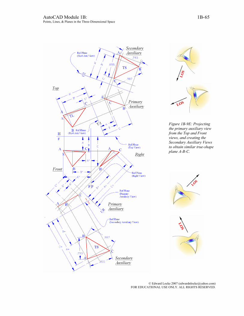
AutoCAD Module 1B: 1B- Points, Lines, & Planes in the Three-Dimensional Space
65
Figure 1B-9E: Projecting the primary auxiliary view from the Top and Front views, and creating the Secondary Auxiliary Views to obtain similar true-shape plane A-B-C.
© Edward Locke 2007 ([email protected]) FOR EDUCATIONAL USE ONLY. ALL RIGHTS RESERVED.
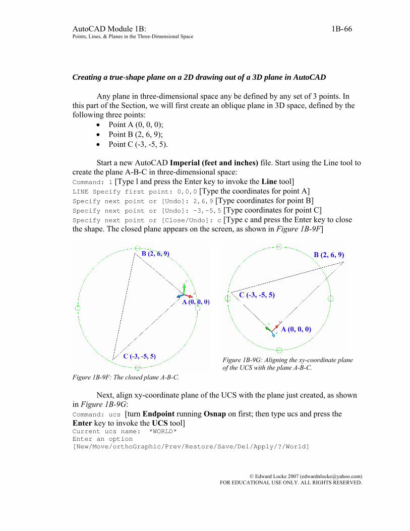
AutoCAD Module 1B: 1B- Points, Lines, & Planes in the Three-Dimensional Space
66
Creating a true-shape plane on a 2D drawing out of a 3D plane in AutoCAD
Any plane in three-dimensional space any be defined by any set of 3 points. In this part of the Section, we will first create an oblique plane in 3D space, defined by the following three points:
• Point A (0, 0, 0); • Point B (2, 6, 9); • Point C (-3, -5, 5). Start a new AutoCAD Imperial (feet and inches) file. Start using the Line tool to
create the plane A-B-C in three-dimensional space: Command: l [Type l and press the Enter key to invoke the Line tool] LINE Specify first point: 0,0,0 [Type the coordinates for point A] Specify next point or [Undo]: 2,6,9 [Type coordinates for point B] Specify next point or [Undo]: -3,-5,5 [Type coordinates for point C] Specify next point or [Close/Undo]: c [Type c and press the Enter key to close the shape. The closed plane appears on the screen, as shown in Figure 1B-9F]
Figure 1B-9F: The closed plane A-B-C.
Figure 1B-9G: Aligning the xy-coordinate plane of the UCS with the plane A-B-C.
Next, align xy-coordinate plane of the UCS with the plane just created, as shown
in Figure 1B-9G: Command: ucs [turn Endpoint running Osnap on first; then type ucs and press the Enter key to invoke the UCS tool] Current ucs name: *WORLD* Enter an option [New/Move/orthoGraphic/Prev/Restore/Save/Del/Apply/?/World]
© Edward Locke 2007 ([email protected]) FOR EDUCATIONAL USE ONLY. ALL RIGHTS RESERVED.
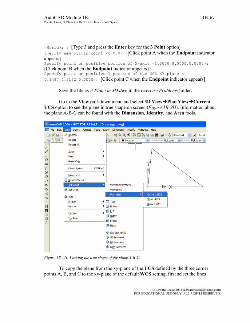
AutoCAD Module 1B: 1B- Points, Lines, & Planes in the Three-Dimensional Space
67
<World>: 3 [Type 3 and press the Enter key for the 3 Point option] Specify new origin point <0,0,0>: [Click point A when the Endpoint indicator appears] Specify point on positive portion of X-axis <1.0000,0.0000,0.0000>: [Click point B when the Endpoint indicator appears] Specify point on positive-Y portion of the UCS XY plane <-0.9487,0.3162,0.0000>: [Click point C when the Endpoint indicator appears]
Save the file as A Plane in 3D.dwg in the Exercise Problems folder.
Go to the View pull-down menu and select 3D View Plan View Current
UCS option to see the plane in true shape on screen (Figure 1B-9H). Information about the plane A-B-C can be found with the Dimension, Identity, and Area tools.
Figure 1B-9H: Viewing the true-shape of the plane A-B-C.
To copy the plane from the xy-plane of the UCS defined by the three corner points A, B, and C to the xy-plane of the default WCS setting, first select the lines
© Edward Locke 2007 ([email protected]) FOR EDUCATIONAL USE ONLY. ALL RIGHTS RESERVED.
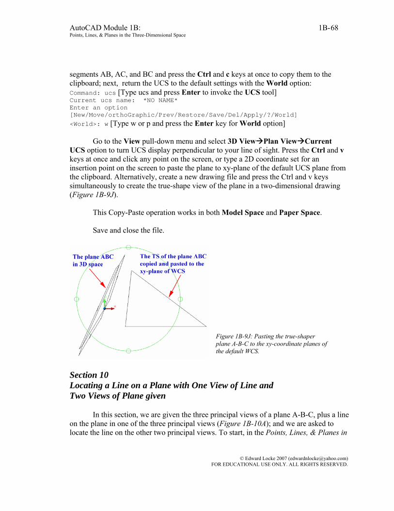
AutoCAD Module 1B: 1B- Points, Lines, & Planes in the Three-Dimensional Space
68
segments AB, AC, and BC and press the Ctrl and c keys at once to copy them to the clipboard; next, return the UCS to the default settings with the World option: Command: ucs [Type ucs and press Enter to invoke the UCS tool] Current ucs name: *NO NAME* Enter an option [New/Move/orthoGraphic/Prev/Restore/Save/Del/Apply/?/World] <World>: w [Type w or p and press the Enter key for World option]
Go to the View pull-down menu and select 3D View Plan View Current UCS option to turn UCS display perpendicular to your line of sight. Press the Ctrl and v keys at once and click any point on the screen, or type a 2D coordinate set for an insertion point on the screen to paste the plane to xy-plane of the default UCS plane from the clipboard. Alternatively, create a new drawing file and press the Ctrl and v keys simultaneously to create the true-shape view of the plane in a two-dimensional drawing (Figure 1B-9J).
This Copy-Paste operation works in both Model Space and Paper Space. Save and close the file.
Figure 1B-9J: Pasting the true-shaper plane A-B-C to the xy-coordinate planes of the default WCS.
Section 10 Locating a Line on a Plane with One View of Line and Two Views of Plane given
In this section, we are given the three principal views of a plane A-B-C, plus a line on the plane in one of the three principal views (Figure 1B-10A); and we are asked to locate the line on the other two principal views. To start, in the Points, Lines, & Planes in
© Edward Locke 2007 ([email protected]) FOR EDUCATIONAL USE ONLY. ALL RIGHTS RESERVED.
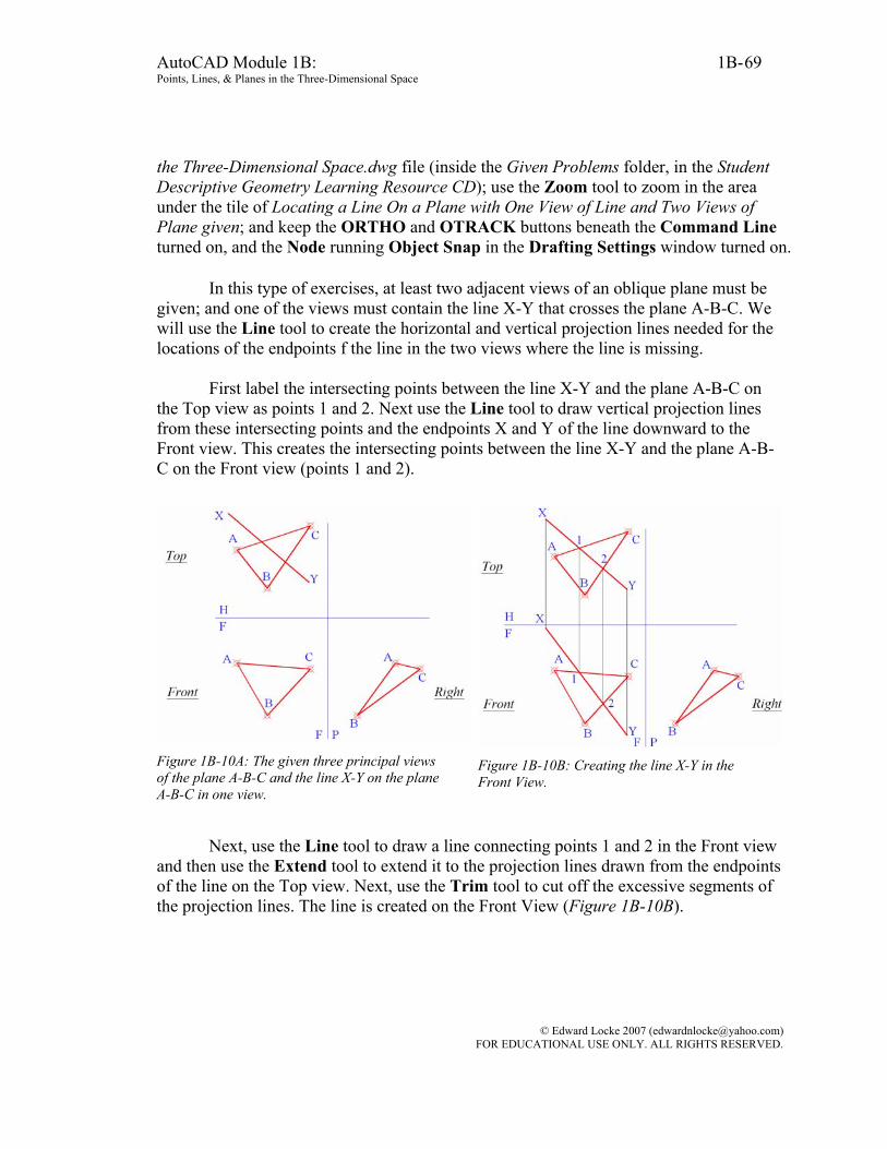
AutoCAD Module 1B: 1B- Points, Lines, & Planes in the Three-Dimensional Space
69
the Three-Dimensional Space.dwg file (inside the Given Problems folder, in the Student Descriptive Geometry Learning Resource CD); use the Zoom tool to zoom in the area under the tile of Locating a Line On a Plane with One View of Line and Two Views of Plane given; and keep the ORTHO and OTRACK buttons beneath the Command Line turned on, and the Node running Object Snap in the Drafting Settings window turned on.
In this type of exercises, at least two adjacent views of an oblique plane must be given; and one of the views must contain the line X-Y that crosses the plane A-B-C. We will use the Line tool to create the horizontal and vertical projection lines needed for the locations of the endpoints f the line in the two views where the line is missing.
First label the intersecting points between the line X-Y and the plane A-B-C on the Top view as points 1 and 2. Next use the Line tool to draw vertical projection lines from these intersecting points and the endpoints X and Y of the line downward to the Front view. This creates the intersecting points between the line X-Y and the plane A-B-C on the Front view (points 1 and 2).
Figure 1B-10A: The given three principal views of the plane A-B-C and the line X-Y on the plane A-B-C in one view.
Figure 1B-10B: Creating the line X-Y in the Front View.
Next, use the Line tool to draw a line connecting points 1 and 2 in the Front view and then use the Extend tool to extend it to the projection lines drawn from the endpoints of the line on the Top view. Next, use the Trim tool to cut off the excessive segments of the projection lines. The line is created on the Front View (Figure 1B-10B).
© Edward Locke 2007 ([email protected]) FOR EDUCATIONAL USE ONLY. ALL RIGHTS RESERVED.

AutoCAD Module 1B: 1B- Points, Lines, & Planes in the Three-Dimensional Space
70
Figure 1B-10C: Projecting the dimensions from the Top View through the miter line to the Right View.
Figure 1B-10D: Creating the line on the Right View.
Next, use the Line tool to draw the line X-Y on the Right view using the miter
line method as follows: Create the horizontal projection lines from points X, Y, 1, 2, on the Top View into the miter line. This creates points of intersection on the miter line. From these intersection points, create the vertical projection lines down to the Right View.
Next, create the horizontal projection lines from points X, Y, 1, 2, on the Front view into the Right View. This creates points of intersection with the vertical projection lines from the miter line (points X, 1, 2, and Y) on the Right View. Next, draw a line connecting points X and Y to finish. Notice again that the same point across the Top view, Front view, miter line intersection and Right side view form a perfect rectangle. Section 11 Locating a Line not on a Plane with One View of the Line and at Least Two Views of the Plane given
In this type of problems, at least two adjacent views of an oblique plane A-B-C are given; and one of the views contains the line X-Y that is NOT on the plane A-B-C (Figure 1B-11A). The students are asked to find the line on the views where it is missing.
To start, in the Points, Lines, & Planes in the Three-Dimensional Space.dwg file
(inside the Given Problems folder, in the Student Descriptive Geometry Learning Resource CD); use the Zoom tool to zoom in the area under the tile of Locating a Line Not on a Plane with One View of the Line and at Least Two Views of the Plane given; and
© Edward Locke 2007 ([email protected]) FOR EDUCATIONAL USE ONLY. ALL RIGHTS RESERVED.

AutoCAD Module 1B: 1B- Points, Lines, & Planes in the Three-Dimensional Space
71
keep the ORTHO and OTRACK buttons beneath the Command Line turned on, and the Node running Object Snap in the Drafting Settings window turned on.
First, use the Line tool to draw vertical projection lines from the endpoints of the line X-Y on the Top View into the Front View. Next use the Extension Line tool to draw a construction line passing through points X and Y of the line on the Top View; this creates the points of intersecting 1 and 2 between the line X-Y and the plane A-B-C on the Top view (Figure 1B-11B).
Figure 1B-11A: The given problem.
Figure 1B-11B: Extending the line X-Y to the plane A-B-C; and creating the vertical projection lines from the Top View to the Front View.
Next draw vertical projection lines from points 1 and 2 on the Top View
downward to the Front View. This creates the points of intersecting 1 and 2 between the line X-Y and the plane A-B-C in the Front View (Figure 1B-11C).
Next, use the Line tool to draw a line connecting points 1, 2 in the front view and then use the Extend tool to extend it to the vertical projection lines drawn from the endpoints of the line X-Y on the top view. The line is created on the front view with endpoints X and Y. Next, use the Trim tool to cut off the excessive segment of the line on the left side of the point X; and use the Point tool to draw two endpoints at X and Y respectively (Figure 1B-11C).
© Edward Locke 2007 ([email protected]) FOR EDUCATIONAL USE ONLY. ALL RIGHTS RESERVED.
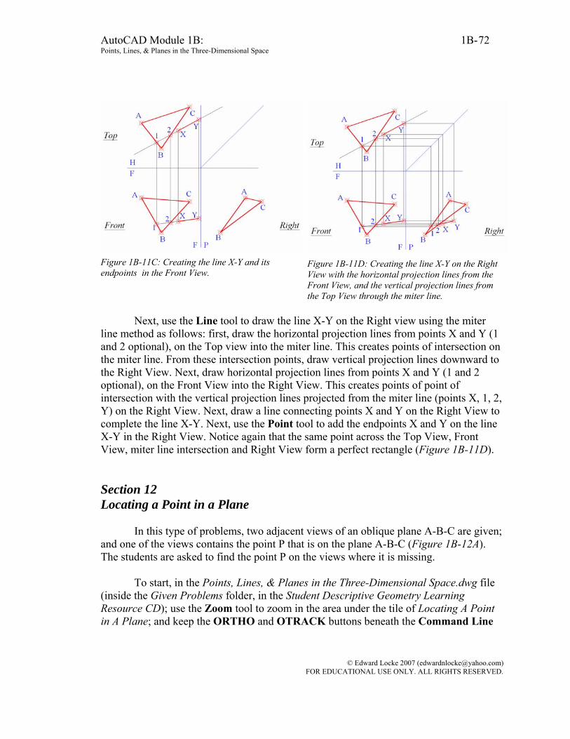
AutoCAD Module 1B: 1B- Points, Lines, & Planes in the Three-Dimensional Space
72
Figure 1B-11C: Creating the line X-Y and its endpoints in the Front View.
Figure 1B-11D: Creating the line X-Y on the Right View with the horizontal projection lines from the Front View, and the vertical projection lines from the Top View through the miter line.
Next, use the Line tool to draw the line X-Y on the Right view using the miter
line method as follows: first, draw the horizontal projection lines from points X and Y (1 and 2 optional), on the Top view into the miter line. This creates points of intersection on the miter line. From these intersection points, draw vertical projection lines downward to the Right View. Next, draw horizontal projection lines from points X and Y (1 and 2 optional), on the Front View into the Right View. This creates points of point of intersection with the vertical projection lines projected from the miter line (points X, 1, 2, Y) on the Right View. Next, draw a line connecting points X and Y on the Right View to complete the line X-Y. Next, use the Point tool to add the endpoints X and Y on the line X-Y in the Right View. Notice again that the same point across the Top View, Front View, miter line intersection and Right View form a perfect rectangle (Figure 1B-11D). Section 12 Locating a Point in a Plane
In this type of problems, two adjacent views of an oblique plane A-B-C are given; and one of the views contains the point P that is on the plane A-B-C (Figure 1B-12A). The students are asked to find the point P on the views where it is missing.
To start, in the Points, Lines, & Planes in the Three-Dimensional Space.dwg file
(inside the Given Problems folder, in the Student Descriptive Geometry Learning Resource CD); use the Zoom tool to zoom in the area under the tile of Locating A Point in A Plane; and keep the ORTHO and OTRACK buttons beneath the Command Line
© Edward Locke 2007 ([email protected]) FOR EDUCATIONAL USE ONLY. ALL RIGHTS RESERVED.

AutoCAD Module 1B: 1B- Points, Lines, & Planes in the Three-Dimensional Space
73
turned on, and the Node running Object Snap in the Drafting Settings window turned on.
First, use the Copy tool to create two additional copies of the given views next to
the original, for additional exercises.
Since the point is on the plane, a construction line can be drawn passing through the point and any of the corner points of the plane and intersecting at the edge on the opposite side of the plane on the view (in this case, the Top View) where the point is given. The point can then be located through projection method on its adjacent view (in this case, the Front View). We will select corner point C to start with.
First, use the Line tool to draw a line connecting points C and P on the Top view; next, use the Extend tool to extend this line to the edge line A-B (the opposite side of the corner angle C). This creates the point of intersecting x on the edge line A-B in the Top View. Next, draw the vertical projection lines from the points x and P on the Top View downward into the Front View. This creates the point of intersecting x on the edge line A-B on the Front View. Next, draw a line connecting the points x and C on the Front View. This creates the location of the point P on the Front View. Next, use the Point tool to create the point P in the Front View (Figure 1B-12B).
Figure 1B-12A: The given problem. Figure 1B-12B: Creating the point P in the Front View with the help of the projection lines.
© Edward Locke 2007 ([email protected]) FOR EDUCATIONAL USE ONLY. ALL RIGHTS RESERVED.

AutoCAD Module 1B: 1B- Points, Lines, & Planes in the Three-Dimensional Space
74
Figure 1B-12C: Creating the point P in the Right View with the help of the projection lines.
Figure 1B-12D: Additional exercise starting from the point A as the corner point.
Figure 1B-12E: Additional exercise starting from the point B as the corner point.
Next, create the point P on the Right View using the miter line method as follows:
Draw a horizontal projection line from points P on the top view into the miter line. This creates a point of intersection on the miter line. From this point of intersecting on the miter line, draw a vertical projection line down to the Right View. Next, draw a horizontal projection line from the point P in the Front View into the Right View. This creates a point of intersection with the vertical projection line. Use the Point tool to create the point P on the right side view. Optionally, the point x can be created in the Right View by the same miter line method (Figure 1B-12C). The location of the point of x on the Right View, unlike the location of the point of x on the Font View, is not required for the solution of the problem. In addition, as an optional step, a construction line can be created connecting the corner point C and the point x on the edge AB, through the point P, in the Right View. Notice again that the points P and x across the Top view, Front view, miter line and Right View form perfect rectangles.
© Edward Locke 2007 ([email protected]) FOR EDUCATIONAL USE ONLY. ALL RIGHTS RESERVED.
AutoCAD Module 1B: 1B- Points, Lines, & Planes in the Three-Dimensional Space
75
We can now use the additional copies of the given views to redo the same project,
starting from the corner points A and B, to draw the corner-point-edge construction line. The results are similar to the above step-by-step example using the point C as the corner point (Figure 1B-12D and Figure 1B-12E).
Save the file.
Section 13 Locating a Point Relative to a Plane
In this section, we will study the techniques of locating a point that is in a position relative to a plane (but not on the plane), in two missing views, when the plane is given in at least two views, and the point is given in one of the views where the plane is given. In this Section, we are concerned only with the relative positions of the point with regard to the plane in the three principal views, not with the exact position of the point with regard to the plane (such as the shortest distance between the point and the plane, or the shortest distance between the point and one of the edges of the plane if both the point and the plane lie on the same coordinate plane).
For this type of problems, two adjacent views of an oblique plane are given; and
one of the views contains the point P that is located in a position relative to the plane A-B-C (Figure 1B-13A). The students are asked to find the point on the views where it is missing. The method used in Section 12 Locate a Point in a Plane can be used to solve this problem.
To start, in the Points, Lines, & Planes in the Three-Dimensional Space.dwg file
(inside the Given Problems folder, in the Student Descriptive Geometry Learning Resource CD); use the Zoom tool to zoom in the area under the tile of Locating A Point Relative to A Plane; and keep the ORTHO and OTRACK buttons beneath the Command Line turned on, and the Node running Object Snap in the Drafting Settings window turned on.
Since the point P is in a position relative to the plane, a construction line can be drawn connecting the point and one of the corner points of the plane through an edge line on the plan, on the view where the point is given (the Top View n this case). The point can then be located through projection method on the adjacent view (the Front View in this case). We will select edge line AC and corner point B to start with.
© Edward Locke 2007 ([email protected]) FOR EDUCATIONAL USE ONLY. ALL RIGHTS RESERVED.

AutoCAD Module 1B: 1B- Points, Lines, & Planes in the Three-Dimensional Space
76
Figure 1B-13A: The given views. Figure 1B-13B: Creating the point x on the edge AC across all three views; and projecting the point P into the Front and Right Views.
First, use the Line tool to draw a line connecting points B and P on the top view, which intersects edge line A-B to create the point of intersection x.
Next, draw a vertical projection line downward into the Front view from the point x. This creates the point of intersecting x on the edge line AC in the Front View. Next, draw a construction line connecting points B and x. Next, from point x in the Top View, draw a horizontal projection line into the miter line; and from the point of intersection on the miter line, draw a vertical projection line downward into the Right View. This creates intersecting point x on the edge line AC on the Right View.
Next, from the point P on the Top View, draw a vertical projection line downward
into the Front view. Next, from the point P on the top view, draw a horizontal projection line into the miter line; then from its point of intersection on the miter line, draw a vertical projection line downward into the Right View (Figure 1B-13B).
Next, use the Extend tool to extend the construction line segment B-x on the Front View to the vertical projection line projected from the point P on the Top View. The point of intersection gives the location for the point P on the Front View. Next, use the Extend tool to extend the construction line segment B-x on the Right View to the vertical projection line drawn from the point P on the Top View through the miter line. The point of intersection gives the location for the point P on the Right View. Next, use the Point tool to create the point P on the Front and right Views (Figure 1B-13C).
Two more examples of locating a point relative to a plane are shown in Figure 1B-13D and Figure 1B-13E.
© Edward Locke 2007 ([email protected]) FOR EDUCATIONAL USE ONLY. ALL RIGHTS RESERVED.
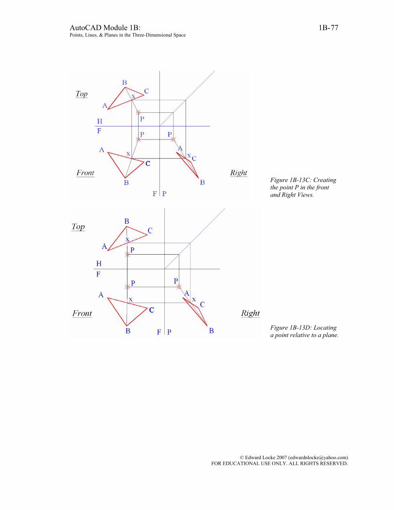
AutoCAD Module 1B: 1B- Points, Lines, & Planes in the Three-Dimensional Space
77
Figure 1B-13C: Creating the point P in the front and Right Views.
Figure 1B-13D: Locating a point relative to a plane.
© Edward Locke 2007 ([email protected]) FOR EDUCATIONAL USE ONLY. ALL RIGHTS RESERVED.
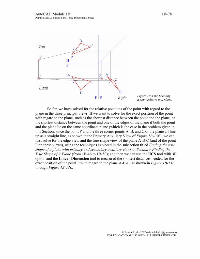
AutoCAD Module 1B: 1B- Points, Lines, & Planes in the Three-Dimensional Space
78
Figure 1B-13E: Locating a point relative to a plane.
So far, we have solved for the relative positions of the point with regard to the
plane in the three principal views. If we want to solve for the exact position of the point with regard to the plane, such as the shortest distance between the point and the plane, or the shortest distance between the point and one of the edges of the plane if both the point and the plane lie on the same coordinate plane (which is the case in the problem given in this Section, since the point P and the three corner points A, B, and C of the plane all line up as a straight line, as shown in the Primary Auxiliary View of Figure 1B-13F), we can first solve for the edge view and the true-shape view of the plane A-B-C (and of the point P on these views), using the techniques explored in the subsection titled Finding the true shape of a plane with primary and secondary auxiliary views of Section 9 Finding the True Shape of A Plane (from 1B-46 to 1B-50); and then we can use the UCS tool with 3P option and the Linear Dimension tool to measured the shortest distances needed for the exact position of the point P with regard to the plane A-B-C, as shown in Figure 1B-13F through Figure 1B-13L.
© Edward Locke 2007 ([email protected]) FOR EDUCATIONAL USE ONLY. ALL RIGHTS RESERVED.
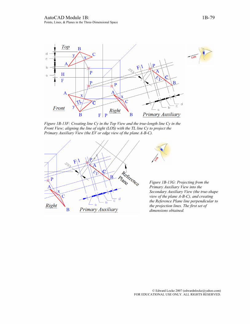
AutoCAD Module 1B: 1B- Points, Lines, & Planes in the Three-Dimensional Space
79
Figure 1B-13F: Creating line Cy in the Top View and the true-length line Cy in the Front View; aligning the line of sight (LOS) with the TL line Cy to project the Primary Auxiliary View (the EV or edge view of the plane A-B-C).
Figure 1B-13G: Projecting from the Primary Auxiliary View into the Secondary Auxiliary View (the true-shape view of the plane A-B-C), and creating the Reference Plane line perpendicular to the projection lines. The first set of dimensions obtained.
© Edward Locke 2007 ([email protected]) FOR EDUCATIONAL USE ONLY. ALL RIGHTS RESERVED.
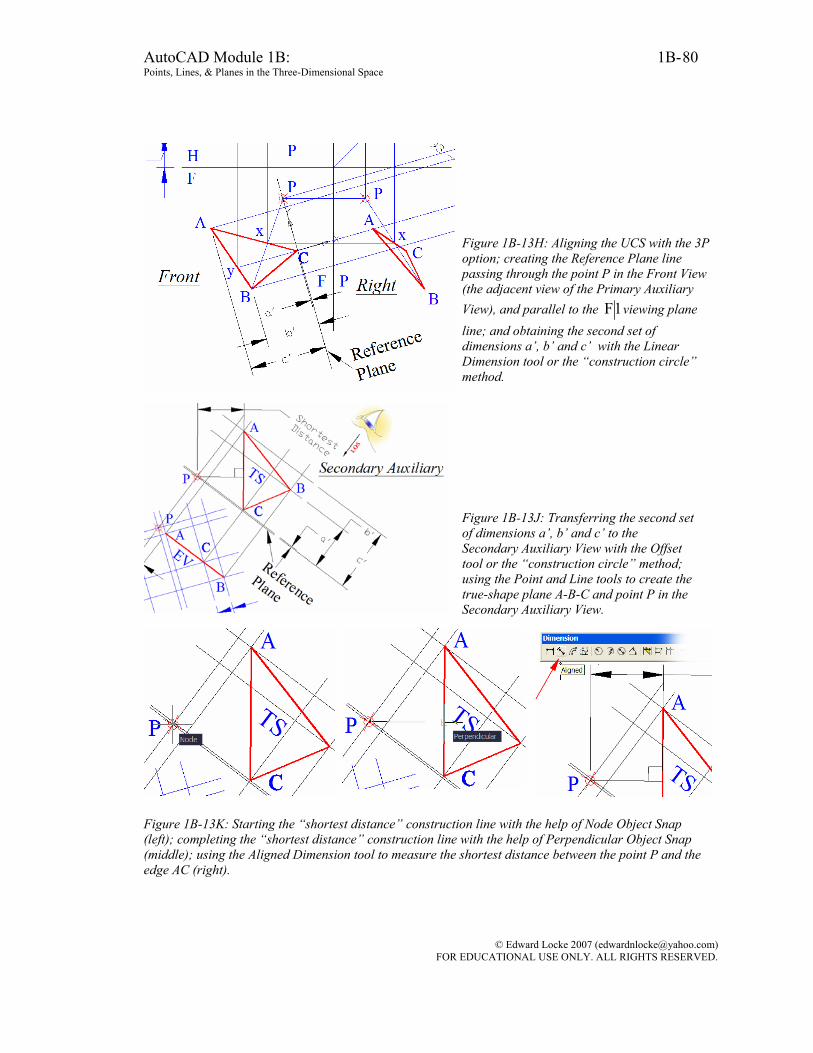
AutoCAD Module 1B: 1B- Points, Lines, & Planes in the Three-Dimensional Space
80
Figure 1B-13H: Aligning the UCS with the 3P option; creating the Reference Plane line passing through the point P in the Front View (the adjacent view of the Primary Auxiliary View), and parallel to the 1F viewing plane line; and obtaining the second set of dimensions a’, b’ and c’ with the Linear Dimension tool or the “construction circle” method.
Figure 1B-13J: Transferring the second set of dimensions a’, b’ and c’ to the Secondary Auxiliary View with the Offset tool or the “construction circle” method; using the Point and Line tools to create the true-shape plane A-B-C and point P in the Secondary Auxiliary View.
Figure 1B-13K: Starting the “shortest distance” construction line with the help of Node Object Snap (left); completing the “shortest distance” construction line with the help of Perpendicular Object Snap (middle); using the Aligned Dimension tool to measure the shortest distance between the point P and the edge AC (right).
© Edward Locke 2007 ([email protected]) FOR EDUCATIONAL USE ONLY. ALL RIGHTS RESERVED.
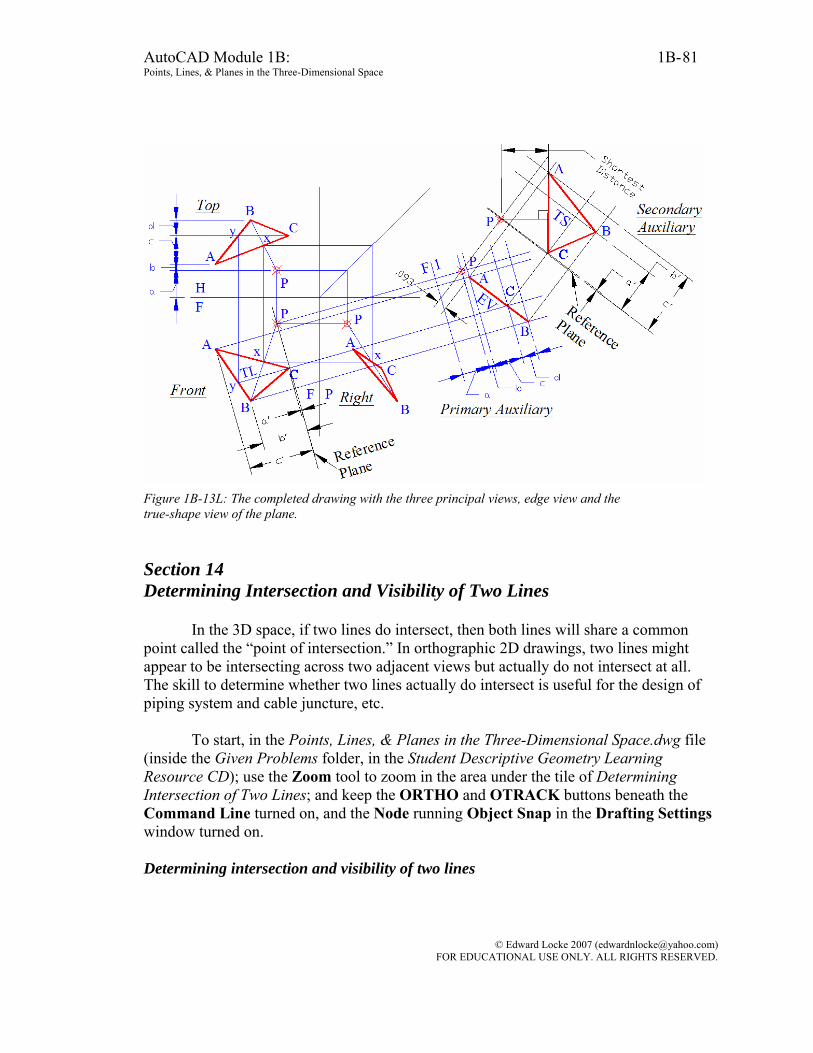
AutoCAD Module 1B: 1B- Points, Lines, & Planes in the Three-Dimensional Space
81
Figure 1B-13L: The completed drawing with the three principal views, edge view and the true-shape view of the plane. Section 14 Determining Intersection and Visibility of Two Lines
In the 3D space, if two lines do intersect, then both lines will share a common point called the “point of intersection.” In orthographic 2D drawings, two lines might appear to be intersecting across two adjacent views but actually do not intersect at all. The skill to determine whether two lines actually do intersect is useful for the design of piping system and cable juncture, etc.
To start, in the Points, Lines, & Planes in the Three-Dimensional Space.dwg file
(inside the Given Problems folder, in the Student Descriptive Geometry Learning Resource CD); use the Zoom tool to zoom in the area under the tile of Determining Intersection of Two Lines; and keep the ORTHO and OTRACK buttons beneath the Command Line turned on, and the Node running Object Snap in the Drafting Settings window turned on. Determining intersection and visibility of two lines
© Edward Locke 2007 ([email protected]) FOR EDUCATIONAL USE ONLY. ALL RIGHTS RESERVED.

AutoCAD Module 1B: 1B- Points, Lines, & Planes in the Three-Dimensional Space
82
In this type of problems, two adjacent views of two lines that “apparently intersect” are given (in this case, the Top and Front Views, as shown in Figure 1B-14A; or the Front and Right Views, as shown in Figure 1B-14B. Notice that in the drawing, the “lines” refer to the central axis lines of the tow pipes AB and CD. We will determine whether these two “apparently intersecting” lines actually do intersect by the following simple test:
If the point where the two lines AB and CD appear to be intersecting (called the “crossing point;” i. e., the point x in Figure 1B-14A and Figure 1B-14B) do align across two adjacent views on the same orthographic projection line, or to be more specific, if a projection line connecting the “crossing point” can be drawn between two given adjacent views (the pair of Top and Front Views, or the pair of Front and Right Views, in this case), such that the projection line is perpendicular to the viewing plane line between the
adjacent views (the FH and the PF lines respectively), then the two lines AB and CD do
actually intersect, as shown in the left side of Figure 1B-14A and in Figure 1B-14B. Otherwise, they do not actually intersect (as shown in the right side of Figure 1B-14A). Lines that do intersect each other are called “intersecting lines” and they touch each other at a “point of intersection.” Lines that do not intersect each other are called “nonintersecting lines” or “skewed lines” and they do not touch each other.
Figure 1B-14A: Two intersecting pipes (left); and two non-intersecting pipes (right)
Figure 1B-14B: Two non-intersecting pipes, with pipe CD both appearing as vertical in the Front and Top Views and requiring a third view to determine intersection.
Two adjacent views are needed to determine if two lines do intersect in 3D space,
provided that both lines do not coincide with the orthographic projection lines, or in other words, they do not appear as horizontal or vertical (Figure 1B-14A). Otherwise, an
© Edward Locke 2007 ([email protected]) FOR EDUCATIONAL USE ONLY. ALL RIGHTS RESERVED.

AutoCAD Module 1B: 1B- Points, Lines, & Planes in the Three-Dimensional Space
83
additional view will be needed, as explained in the following special case study (Figure 1B-14B):
As shown in Figure 1B-14B, the Top and Front Views of lines AB and CD are given, where line CD appears as vertical on the Top and Front views, and coincides with the vertical orthographic projection line. We first used the “miter line” method to create the Right View. After this step, we use the Front and Right Views to draw horizontal projection lines connecting the crossing point x across these two view. The point x does not align horizontally (in other words, perpendicularly relative to the PF viewing plane line) across both views. Therefore, we determine that line A-B and line C-D does not intersect Pipe drawing convention
Before we proceed to solving problems of intersection and visibility of two lines
(or in real-world application, two pipes or cables), we will discuss some drafting conventions related to this type of problems (Figure 1B-14C and Figure 1B-14D):
• Central axes: The central axes of the pipes or cables are the lines used in the
determination of intersection and visibility; • Point of intersection: The point of intersection is the location where the
central axes of the pipes or cables meet (the point x in Figure 1B-14C, where the intersection is not determined yet); or
• Point of apparent intersection: The point of apparent intersection is the
location where the central axes of the pipes or cables appear to meet on a particular view (also, the point x in Figure 1B-14C, where the intersection is not determined yet);
• Area around the actual point of intersection: If the pipes or cables actually
intersect, then for all practical purposes, straight lines forming a cross can be used to indicate the intersection, as shown on the left side of Figure 1B-14D. In the true orthographic projection, the intersection curves are more complicated (as shown and explained in Figure 1B-14E through Figure 1B-14H); or
• Area around the apparent point of intersection: If the pipes or cables do
not intersect, then in the area around the apparent point of intersection, one
© Edward Locke 2007 ([email protected]) FOR EDUCATIONAL USE ONLY. ALL RIGHTS RESERVED.
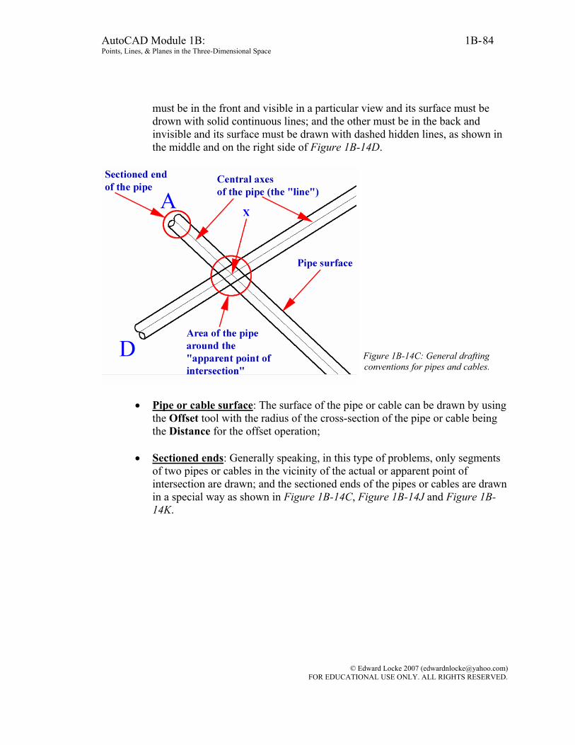
AutoCAD Module 1B: 1B- Points, Lines, & Planes in the Three-Dimensional Space
84
must be in the front and visible in a particular view and its surface must be drown with solid continuous lines; and the other must be in the back and invisible and its surface must be drawn with dashed hidden lines, as shown in the middle and on the right side of Figure 1B-14D.
Figure 1B-14C: General drafting conventions for pipes and cables.
• Pipe or cable surface: The surface of the pipe or cable can be drawn by using
the Offset tool with the radius of the cross-section of the pipe or cable being the Distance for the offset operation;
• Sectioned ends: Generally speaking, in this type of problems, only segments
of two pipes or cables in the vicinity of the actual or apparent point of intersection are drawn; and the sectioned ends of the pipes or cables are drawn in a special way as shown in Figure 1B-14C, Figure 1B-14J and Figure 1B-14K.
© Edward Locke 2007 ([email protected]) FOR EDUCATIONAL USE ONLY. ALL RIGHTS RESERVED.
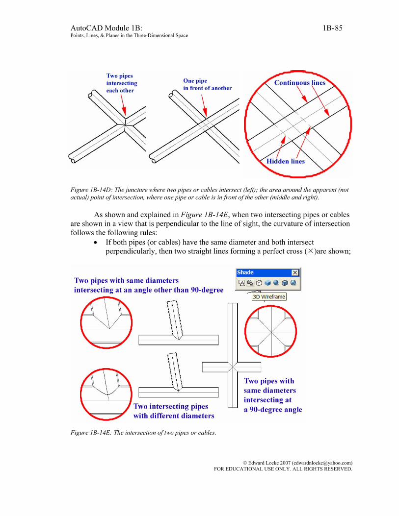
AutoCAD Module 1B: 1B- Points, Lines, & Planes in the Three-Dimensional Space
85
Figure 1B-14D: The juncture where two pipes or cables intersect (left); the area around the apparent (not actual) point of intersection, where one pipe or cable is in front of the other (middle and right).
As shown and explained in Figure 1B-14E, when two intersecting pipes or cables are shown in a view that is perpendicular to the line of sight, the curvature of intersection follows the following rules:
• If both pipes (or cables) have the same diameter and both intersect perpendicularly, then two straight lines forming a perfect cross ( )are shown;
Figure 1B-14E: The intersection of two pipes or cables.
© Edward Locke 2007 ([email protected]) FOR EDUCATIONAL USE ONLY. ALL RIGHTS RESERVED.
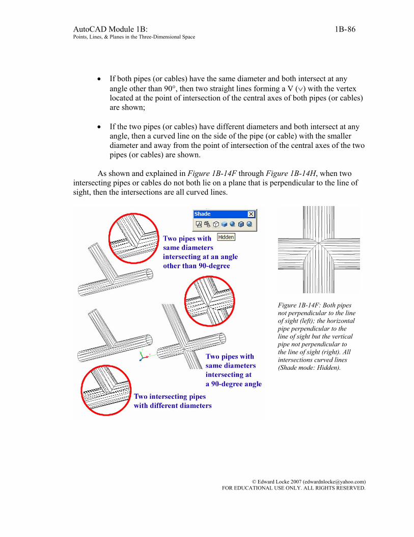
AutoCAD Module 1B: 1B- Points, Lines, & Planes in the Three-Dimensional Space
86
• If both pipes (or cables) have the same diameter and both intersect at any angle other than 90°, then two straight lines forming a V (∨) with the vertex located at the point of intersection of the central axes of both pipes (or cables) are shown;
• If the two pipes (or cables) have different diameters and both intersect at any
angle, then a curved line on the side of the pipe (or cable) with the smaller diameter and away from the point of intersection of the central axes of the two pipes (or cables) are shown.
As shown and explained in Figure 1B-14F through Figure 1B-14H, when two
intersecting pipes or cables do not both lie on a plane that is perpendicular to the line of sight, then the intersections are all curved lines.
Figure 1B-14F: Both pipes not perpendicular to the line of sight (left); the horizontal pipe perpendicular to the line of sight but the vertical pipe not perpendicular to the line of sight (right). All intersections curved lines (Shade mode: Hidden).
© Edward Locke 2007 ([email protected]) FOR EDUCATIONAL USE ONLY. ALL RIGHTS RESERVED.
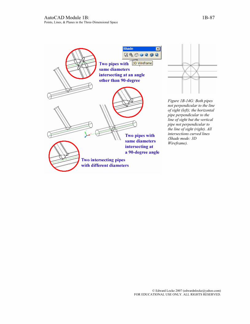
AutoCAD Module 1B: 1B- Points, Lines, & Planes in the Three-Dimensional Space
87
Figure 1B-14G: Both pipes not perpendicular to the line of sight (left); the horizontal pipe perpendicular to the line of sight but the vertical pipe not perpendicular to the line of sight (right). All intersections curved lines (Shade mode: 3D Wireframe).
© Edward Locke 2007 ([email protected]) FOR EDUCATIONAL USE ONLY. ALL RIGHTS RESERVED.
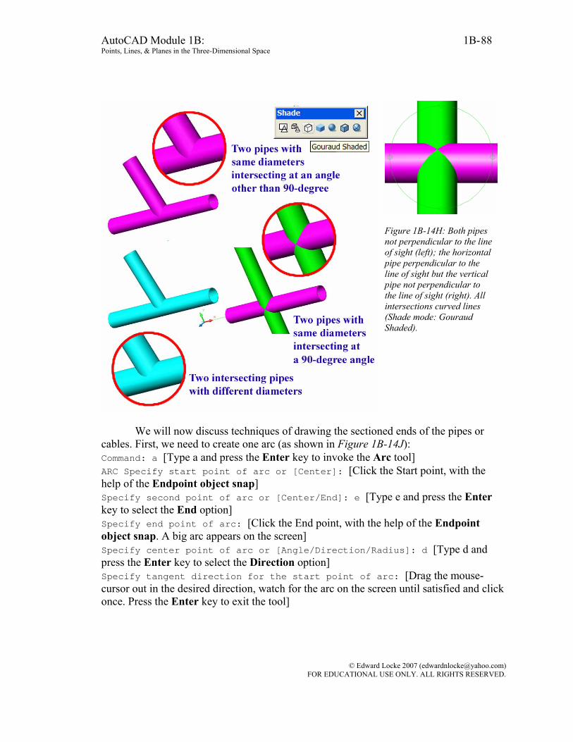
AutoCAD Module 1B: 1B- Points, Lines, & Planes in the Three-Dimensional Space
88
Figure 1B-14H: Both pipes not perpendicular to the line of sight (left); the horizontal pipe perpendicular to the line of sight but the vertical pipe not perpendicular to the line of sight (right). All intersections curved lines (Shade mode: Gouraud Shaded).
We will now discuss techniques of drawing the sectioned ends of the pipes or
cables. First, we need to create one arc (as shown in Figure 1B-14J): Command: a [Type a and press the Enter key to invoke the Arc tool] ARC Specify start point of arc or [Center]: [Click the Start point, with the help of the Endpoint object snap] Specify second point of arc or [Center/End]: e [Type e and press the Enter key to select the End option] Specify end point of arc: [Click the End point, with the help of the Endpoint object snap. A big arc appears on the screen] Specify center point of arc or [Angle/Direction/Radius]: d [Type d and press the Enter key to select the Direction option] Specify tangent direction for the start point of arc: [Drag the mouse-cursor out in the desired direction, watch for the arc on the screen until satisfied and click once. Press the Enter key to exit the tool]
© Edward Locke 2007 ([email protected]) FOR EDUCATIONAL USE ONLY. ALL RIGHTS RESERVED.

AutoCAD Module 1B: 1B- Points, Lines, & Planes in the Three-Dimensional Space
89
Figure 1B-14J: Setting the Start point of the arc (left); the “big arc” displayed after the setting of the End point (middle); dragging the mouse-cursor out in the desired direction (right).
Figure 1B-14K: Creating the first mirrored copy (left); and creating the second mirrored copy (right).
Next, we need to copy the arc (as shown in Figure 1B-14K):
Command: mi [Type mi and press the Enter key to invoke the Mirror tool] MIRROR Select objects: [Click-select the arc] 1 found Select objects: [Press the Enter key to end selection] Specify first point of mirror line: [Click-select the endpoint of the central axis line, with the help of the Endpoint Object Snap] Specify second point of mirror line: [Move the mouse-cursor along the central axis line (dotted tracking line appears on the screen); and click once when a Intersection Object Snap symbol appears close to the Crosshair that follows the mouse-cursor. The mirrored copy appears on the screen on the other side the central axis line (the “mirror line”)] Erase source objects? [Yes/No] <N>: [Press the Enter key to accept the default option of No. The first mirrored copy is created. Press the Enter key to invoke the Mirror tool again] Command: MIRROR
© Edward Locke 2007 ([email protected]) FOR EDUCATIONAL USE ONLY. ALL RIGHTS RESERVED.
AutoCAD Module 1B: 1B- Points, Lines, & Planes in the Three-Dimensional Space
90
Select objects: [Click-select the first mirrored copy of the arc] 1 found Select objects: [Press the Enter key to end selection] Specify first point of mirror line: [Click-select the “First point of mirror line,” with the help of the Endpoint Object Snap] Specify second point of mirror line: [Click-select the “Second point of mirror line,” with the help of the Endpoint Object Snap. The mirrored copy appears on the screen on the other side the mirror line defined by the two points selected] Erase source objects? [Yes/No] <N>: [Press the Enter key to accept the default option of No. The second mirrored copy is created] Determining visibility of a line in a 2d orthographic drawing
If two lines exist in the three-dimensional space, are not parallel but do not intersect each other, then they can appear as intersecting each other in the three principal views, while in reality, one line is in front of the other at the “apparent point of intersection” in a particular view, and thus, is “visible” at this point. By “visibility” we practically mean the relative position of two lines with respect to each other. The determination of visibility of a line at the “apparent point of intersection” is very important in piping design.
To start, in the Points, Lines, & Planes in the Three-Dimensional Space.dwg file
(inside the Given Problems folder, in the Student Descriptive Geometry Learning Resource CD); use the Zoom tool to zoom in the area under the tile of Determining Visibility of a Line in a 2D Orthographic Drawing; and keep the ORTHO and OTRACK buttons beneath the Command Line turned on, and the Node running Object Snap in the Drafting Settings window turned on.
In this type of problems, two adjacent views of two lines (or pipes) are given (the Top and Front Views in this case, as shown in Figure 1B-14A). Before we start thinking about “visibility,” we need to determine if the two lines actually intersect; if they do, then the two lines have an actual point of intersection rather than an “apparent point of intersection; and the problem of “visibility” of one line relative to the other line at the “apparent point of intersection” will not exist. We can use the simple test explored in Section 14 to accomplish this task. As shown in Figure 1B-14A, it is apparent that the “apparent point of intersection” between pipes AB and CD in the two adjacent views
(Top and Front Views) do not align vertically r perpendicularly relative to the FH
viewing plane line; therefore, the pipes AB and CD do not actually intersect; and we need to solve for “visibility.”
© Edward Locke 2007 ([email protected]) FOR EDUCATIONAL USE ONLY. ALL RIGHTS RESERVED.
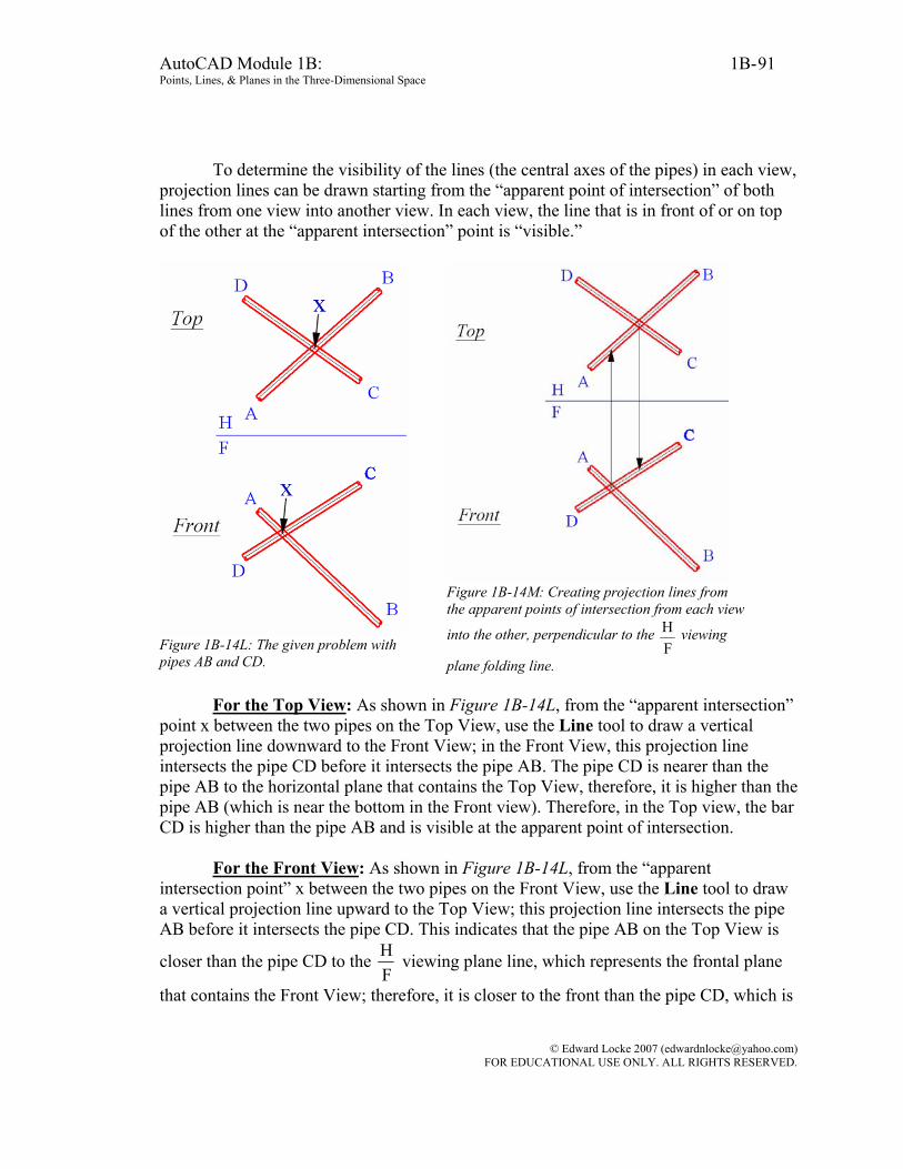
AutoCAD Module 1B: 1B- Points, Lines, & Planes in the Three-Dimensional Space
91
To determine the visibility of the lines (the central axes of the pipes) in each view, projection lines can be drawn starting from the “apparent point of intersection” of both lines from one view into another view. In each view, the line that is in front of or on top of the other at the “apparent intersection” point is “visible.”
Figure 1B-14L: The given problem with pipes AB and CD.
Figure 1B-14M: Creating projection lines from the apparent points of intersection from each view
into the other, perpendicular to the FH viewing
plane folding line.
For the Top View: As shown in Figure 1B-14L, from the “apparent intersection” point x between the two pipes on the Top View, use the Line tool to draw a vertical projection line downward to the Front View; in the Front View, this projection line intersects the pipe CD before it intersects the pipe AB. The pipe CD is nearer than the pipe AB to the horizontal plane that contains the Top View, therefore, it is higher than the pipe AB (which is near the bottom in the Front view). Therefore, in the Top view, the bar CD is higher than the pipe AB and is visible at the apparent point of intersection.
For the Front View: As shown in Figure 1B-14L, from the “apparent intersection point” x between the two pipes on the Front View, use the Line tool to draw a vertical projection line upward to the Top View; this projection line intersects the pipe AB before it intersects the pipe CD. This indicates that the pipe AB on the Top View is
closer than the pipe CD to the FH viewing plane line, which represents the frontal plane
that contains the Front View; therefore, it is closer to the front than the pipe CD, which is
© Edward Locke 2007 ([email protected]) FOR EDUCATIONAL USE ONLY. ALL RIGHTS RESERVED.

AutoCAD Module 1B: 1B- Points, Lines, & Planes in the Three-Dimensional Space
92
near the top of the Top View (or farther away from the frontal plane. Therefore, in the Front View, the pipe AB is in the front of the pipe CD and visible at the apparent point of intersection.
Once we have determined the visibility of each pipe in both views, we use appropriate AutoCAD drawing tools to change the line type of the “invisible” portion into Hidden lines, as shown in Figure 1B-14N.
Save the file.
Figure 1B-14N: Changing the line type of invisible portions of the pipes into Hidden lines.
Figure 1B-14P: Two pipes on the screen in the Model Space, in a SE Isometric view.
Determining the visibility of a pipe created in the three-dimensional space
In AutoCAD, if we create two line in three-dimensional space with three-dimensional Absolute Coordinate Entry using (x,y,z), or use 3D modeling tools to create two solid cylinders or pipes, we can easily determine their visibility in the three-dimensional space (in the Model Space), or in a two-dimensional layout drawing based on these 3D models (in the Layout Space). To start, open the file Visibility of Lines with Two Pipes.dwg in the Student Descriptive Geometry Learning Resource CD. Two pipes (one red and the other green) appear on the screen in the Model Space, in a SE Isometric
© Edward Locke 2007 ([email protected]) FOR EDUCATIONAL USE ONLY. ALL RIGHTS RESERVED.
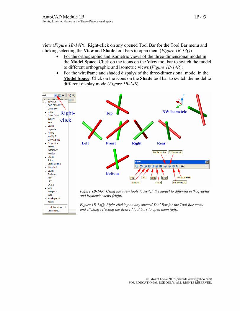
AutoCAD Module 1B: 1B- Points, Lines, & Planes in the Three-Dimensional Space
93
view (Figure 1B-14P). Right-click on any opened Tool Bar for the Tool Bar menu and clicking selecting the View and Shade tool bars to open them (Figure 1B-14Q).
• For the orthographic and isometric views of the three-dimensional model in the Model Space: Click on the icons on the View tool bar to switch the model to different orthographic and isometric views (Figure 1B-14R);
• For the wireframe and shaded dispalys of the three-dimensional model in the Model Space: Click on the icons on the Shade tool bar to switch the model to different display mode (Figure 1B-14S).
Figure 1B-14R: Using the View tools to switch the model to different orthographic and isometric views (right). Figure 1B-14Q: Right-clicking on any opened Tool Bar for the Tool Bar menu and clicking selecting the desired tool bars to open them (left).
© Edward Locke 2007 ([email protected]) FOR EDUCATIONAL USE ONLY. ALL RIGHTS RESERVED.
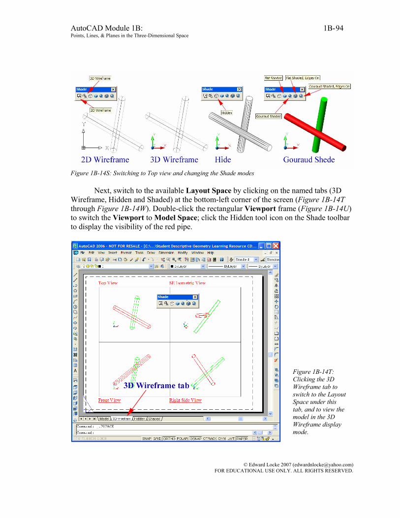
AutoCAD Module 1B: 1B- Points, Lines, & Planes in the Three-Dimensional Space
94
Figure 1B-14S: Switching to Top view and changing the Shade modes Next, switch to the available Layout Space by clicking on the named tabs (3D
Wireframe, Hidden and Shaded) at the bottom-left corner of the screen (Figure 1B-14T through Figure 1B-14W). Double-click the rectangular Viewport frame (Figure 1B-14U) to switch the Viewport to Model Space; click the Hidden tool icon on the Shade toolbar to display the visibility of the red pipe.
Figure 1B-14T: Clicking the 3D Wireframe tab to switch to the Layout Space under this tab, and to view the model in the 3D Wireframe display mode.
© Edward Locke 2007 ([email protected]) FOR EDUCATIONAL USE ONLY. ALL RIGHTS RESERVED.
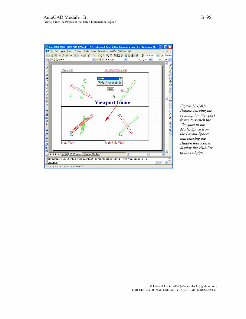
AutoCAD Module 1B: 1B- Points, Lines, & Planes in the Three-Dimensional Space
95
Figure 1B-14U: Double-clicking the rectangular Viewport frame to switch the Viewport to the Model Space from the Layout Space; and clicking the Hidden tool icon to display the visibility of the red pipe.
© Edward Locke 2007 ([email protected]) FOR EDUCATIONAL USE ONLY. ALL RIGHTS RESERVED.
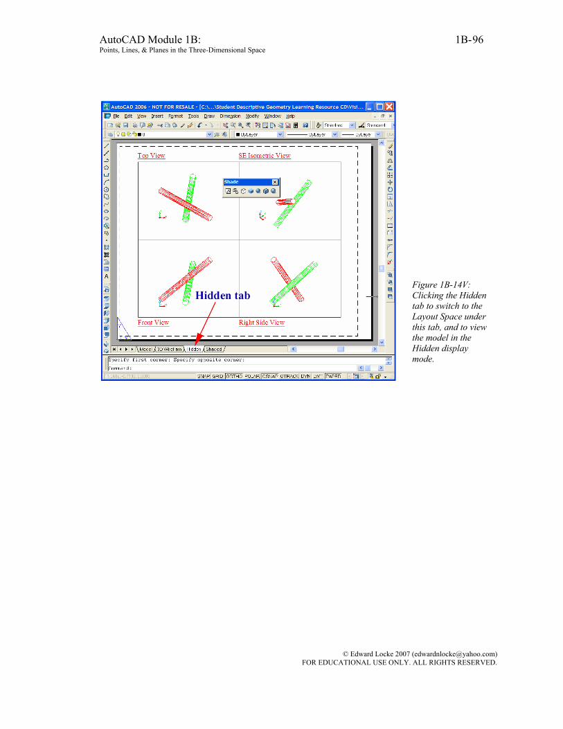
AutoCAD Module 1B: 1B- Points, Lines, & Planes in the Three-Dimensional Space
96
Figure 1B-14V: Clicking the Hidden tab to switch to the Layout Space under this tab, and to view the model in the Hidden display mode.
© Edward Locke 2007 ([email protected]) FOR EDUCATIONAL USE ONLY. ALL RIGHTS RESERVED.
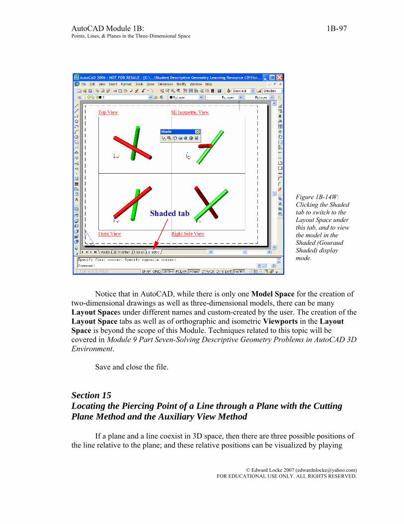
AutoCAD Module 1B: 1B- Points, Lines, & Planes in the Three-Dimensional Space
97
Figure 1B-14W: Clicking the Shaded tab to switch to the Layout Space under this tab, and to view the model in the Shaded (Gouraud Shaded) display mode.
Notice that in AutoCAD, while there is only one Model Space for the creation of
two-dimensional drawings as well as three-dimensional models, there can be many Layout Spaces under different names and custom-created by the user. The creation of the Layout Space tabs as well as of orthographic and isometric Viewports in the Layout Space is beyond the scope of this Module. Techniques related to this topic will be covered in Module 9 Part Seven-Solving Descriptive Geometry Problems in AutoCAD 3D Environment.
Save and close the file.
Section 15 Locating the Piercing Point of a Line through a Plane with the Cutting Plane Method and the Auxiliary View Method
If a plane and a line coexist in 3D space, then there are three possible positions of the line relative to the plane; and these relative positions can be visualized by playing
© Edward Locke 2007 ([email protected]) FOR EDUCATIONAL USE ONLY. ALL RIGHTS RESERVED.
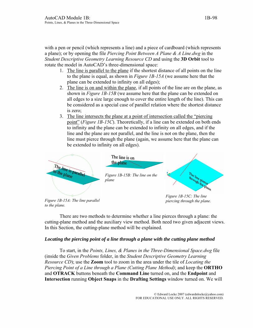
AutoCAD Module 1B: 1B- Points, Lines, & Planes in the Three-Dimensional Space
98
with a pen or pencil (which represents a line) and a piece of cardboard (which represents a plane); or by opening the file Piercing Point Between A Plane & A Line.dwg in the Student Descriptive Geometry Learning Resource CD and using the 3D Orbit tool to rotate the model in AutoCAD’s three-dimensional space:
1. The line is parallel to the plane if the shortest distance of all points on the line to the plane is equal, as shown in Figure 1B-15A (we assume here that the plane can be extended to infinity on all edges);
2. The line is on and within the plane, if all points of the line are on the plane, as shown in Figure 1B-15B (we assume here that the plane can be extended on all edges to a size large enough to cover the entire length of the line). This can be considered as a special case of parallel relation where the shortest distance is zero;
3. The line intersects the plane at a point of intersection called the “piercing point” (Figure 1B-15C). Theoretically, if a line can be extended on both ends to infinity and the plane can be extended to infinity on all edges, and if the line and the plane are not parallel, and the line is not on the plane, then the line must pierce through the plane (again, we assume here that the plane can be extended to infinity on all edges).
Figure 1B-15A: The line parallel to the plane.
Figure 1B-15B: The line on the plane
Figure 1B-15C: The line piercing through the plane.
There are two methods to determine whether a line pierces through a plane: the
cutting-plane method and the auxiliary view method. Both need two given adjacent views. In this Section, the cutting-plane method will be explained. Locating the piercing point of a line through a plane with the cutting plane method
To start, in the Points, Lines, & Planes in the Three-Dimensional Space.dwg file (inside the Given Problems folder, in the Student Descriptive Geometry Learning Resource CD); use the Zoom tool to zoom in the area under the tile of Locating the Piercing Point of a Line through a Plane (Cutting Plane Method); and keep the ORTHO and OTRACK buttons beneath the Command Line turned on, and the Endpoint and Intersection running Object Snaps in the Drafting Settings window turned on. We will
© Edward Locke 2007 ([email protected]) FOR EDUCATIONAL USE ONLY. ALL RIGHTS RESERVED.

AutoCAD Module 1B: 1B- Points, Lines, & Planes in the Three-Dimensional Space
99
use the Line tool to create the horizontal and vertical projection lines needed for determining whether the line A-B pierces through the plane 1-2-3.
As shown in Figure 1B-15D, the Top and Front Views of line A-B and plane 1-2-
3 are given. We will determine whether the line pierces through the plane or not in the following step-by-step procedures.
Figure 1B-15D: The given views.
Figure 1B-15E: Creating the initial projection lines.
First, on the Top View, use the Line tool with the help of Endpoint Object Snap
to draw a construction line connecting the points x and y where the line A-B appears to touch the plane 1-2-3. Imagine this construction line as the top edge of a cutting-plane that includes the line A-B. Next, from the points x and y on the Top View, draw vertical projection lines into the Front View; this creates the points of intersecting x and y in the Front View. Draw construction line x-y in the Front view (Figure 1B-15E).
Next, on the Front view, draw a construction line connecting the points u and v where the line A-B appears to touch the edges of the plane 1-2-3. Now, construction lines u-v and x-y intersect to create the point of intersection o in the Front view, which is the point where the line A-B pierces through the plane 1-2-3. Next, draw a projection line to project the piercing point o from the Front view into the Top view (Figure 1B-15F).
Once the piercing point is determined on the Top and Front views, we need to
determine the visibility of the portions of line A-B on both side of the piercing point o, in both Top and Front views. We should first make an analysis of the spatial positions of the portions of the line A-B (within the edges of the plane on both Top and Front views) relative to the plane 1-2-3.
© Edward Locke 2007 ([email protected]) FOR EDUCATIONAL USE ONLY. ALL RIGHTS RESERVED.
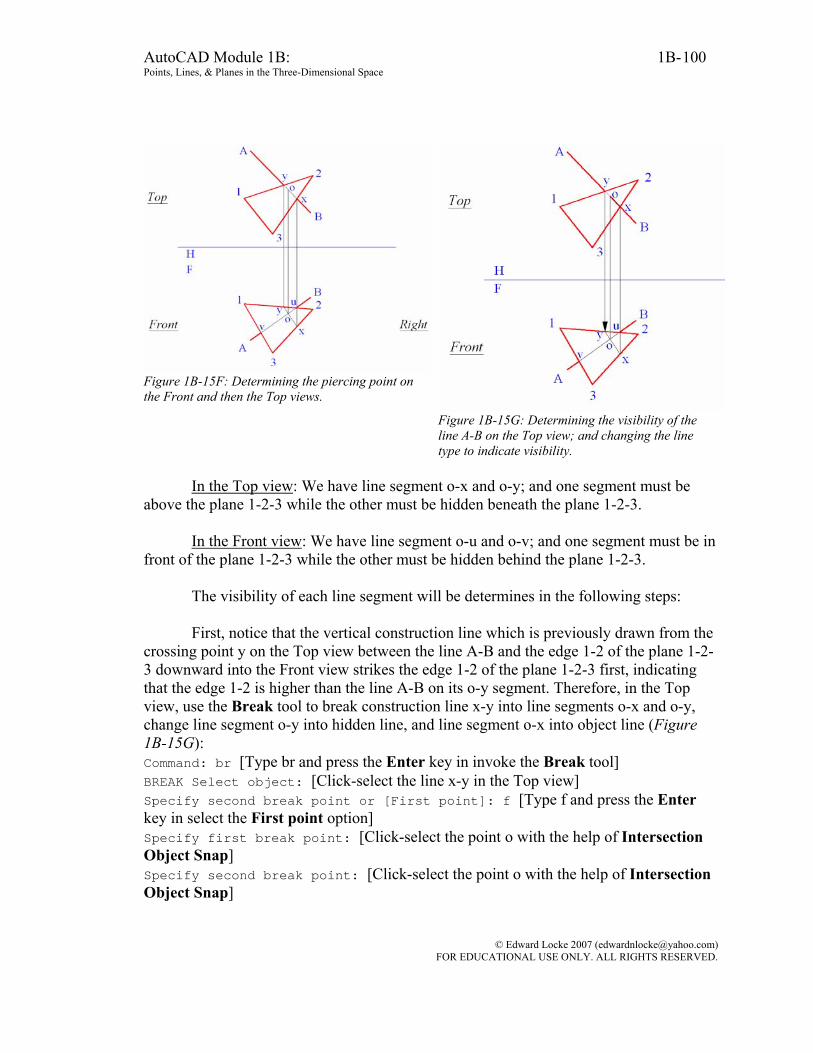
AutoCAD Module 1B: 1B- Points, Lines, & Planes in the Three-Dimensional Space
100
Figure 1B-15F: Determining the piercing point on the Front and then the Top views.
Figure 1B-15G: Determining the visibility of the line A-B on the Top view; and changing the line type to indicate visibility.
In the Top view: We have line segment o-x and o-y; and one segment must be
above the plane 1-2-3 while the other must be hidden beneath the plane 1-2-3. In the Front view: We have line segment o-u and o-v; and one segment must be in
front of the plane 1-2-3 while the other must be hidden behind the plane 1-2-3. The visibility of each line segment will be determines in the following steps:
First, notice that the vertical construction line which is previously drawn from the
crossing point y on the Top view between the line A-B and the edge 1-2 of the plane 1-2-3 downward into the Front view strikes the edge 1-2 of the plane 1-2-3 first, indicating that the edge 1-2 is higher than the line A-B on its o-y segment. Therefore, in the Top view, use the Break tool to break construction line x-y into line segments o-x and o-y, change line segment o-y into hidden line, and line segment o-x into object line (Figure 1B-15G): Command: br [Type br and press the Enter key in invoke the Break tool] BREAK Select object: [Click-select the line x-y in the Top view] Specify second break point or [First point]: f [Type f and press the Enter key in select the First point option] Specify first break point: [Click-select the point o with the help of Intersection Object Snap] Specify second break point: [Click-select the point o with the help of Intersection Object Snap]
© Edward Locke 2007 ([email protected]) FOR EDUCATIONAL USE ONLY. ALL RIGHTS RESERVED.
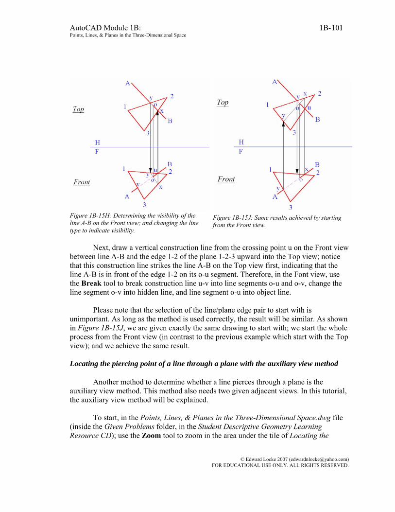
AutoCAD Module 1B: 1B- Points, Lines, & Planes in the Three-Dimensional Space
101
Figure 1B-15H: Determining the visibility of the line A-B on the Front view; and changing the line type to indicate visibility.
Figure 1B-15J: Same results achieved by starting from the Front view.
Next, draw a vertical construction line from the crossing point u on the Front view
between line A-B and the edge 1-2 of the plane 1-2-3 upward into the Top view; notice that this construction line strikes the line A-B on the Top view first, indicating that the line A-B is in front of the edge 1-2 on its o-u segment. Therefore, in the Font view, use the Break tool to break construction line u-v into line segments o-u and o-v, change the line segment o-v into hidden line, and line segment o-u into object line.
Please note that the selection of the line/plane edge pair to start with is unimportant. As long as the method is used correctly, the result will be similar. As shown in Figure 1B-15J, we are given exactly the same drawing to start with; we start the whole process from the Front view (in contrast to the previous example which start with the Top view); and we achieve the same result. Locating the piercing point of a line through a plane with the auxiliary view method
Another method to determine whether a line pierces through a plane is the auxiliary view method. This method also needs two given adjacent views. In this tutorial, the auxiliary view method will be explained.
To start, in the Points, Lines, & Planes in the Three-Dimensional Space.dwg file
(inside the Given Problems folder, in the Student Descriptive Geometry Learning Resource CD); use the Zoom tool to zoom in the area under the tile of Locating the
© Edward Locke 2007 ([email protected]) FOR EDUCATIONAL USE ONLY. ALL RIGHTS RESERVED.

AutoCAD Module 1B: 1B- Points, Lines, & Planes in the Three-Dimensional Space
102
Piercing Point of a Line through a Plane (Auxiliary View Method); and keep the ORTHO and OTRACK buttons beneath the Command Line turned on, and the Endpoint and Intersection running Object Snaps in the Drafting Settings window turned on. We will use the Line tool to create the horizontal and vertical projection lines needed for determining whether the line A-B pierces through the plane 1-2-3.
As shown in Figure 1B-15K, the Top and Front views of line A-B and plane 1-2-3
are given. We will determine whether the line pierces through the plane or not, in the following step-by-step procedures. To prove that both the cutting-plane method and the auxiliary view method will yield exactly the same results, we actually use the same drawing as what we used in the previous part of this Section on cutting-plane method (as shown Figure 1B-15P and Figure 1B-15Q later, both method yield exactly the same result).
The key strategy in the auxiliary view method is to create an edge view of the plane 1-2-3. This can be accomplished by the following step-by-step procedures:
Figure 1B-15K: Creating the foreshortened line 1-x
on the plane 1-2-3 and parallel to the FH
viewing
plane line in the Top view; and projecting it from the Top view to the Front view to create the TL line 1-x.
Figure 1B-15L: Starting the Auxiliary view by projecting from the TL line 1-x from the Front view; and creating the Ref Plane Line perpendicular to these projection lines.
First, create a TL (true-length) line on the plane 1-2-3. Draw a line parallel to the
horizontal FH viewing plane line on the plane 1-2-3 in either the Top or the Front view
(in this case, we select the Top view to start with, as shown in Figure 1B-15K). This
© Edward Locke 2007 ([email protected]) FOR EDUCATIONAL USE ONLY. ALL RIGHTS RESERVED.

AutoCAD Module 1B: 1B- Points, Lines, & Planes in the Three-Dimensional Space
103
creates the foreshortened line 1-x on the Top view, which is on the plane 1-2-3 in the 3D space. Next, draw a vertical projection line from the point x in the Top view downward into the Front view, creating the point x in the Front view. After this, draw the line connecting the points 1 and x in the Front view, which is the true-length line (TL) 1-x. Next, use the UCS tool with the 3 Point option to align the xy-axes of the UCS with the TL line 1-x in the Front view; and with the ORTHO on, use the Line tool to create projection lines from the corner points 1, 2, and 3 of the plane 1-2-3, and from the end points A and B of the line A-B in the Front view, into the Auxiliary view; in addition, create the reference plane line for the Auxiliary view perpendicular to these projection lines (Ref Plane Line in Figure 1B-15L). This Reference Plane Line corresponds to the
horizontal FH viewing plane line between the Top and Front views. The projection line
that passes through the points 1 and x in the Front view is also parallel to the line of sight (abbreviated as LOS) along which the observer is viewing the plane 1-2-3 from the Auxiliary view (Figure 1B-15L). The first set of dimensions for the Auxiliary view is obtained.
© Edward Locke 2007 ([email protected]) FOR EDUCATIONAL USE ONLY. ALL RIGHTS RESERVED.
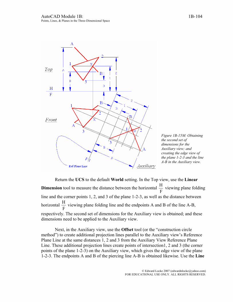
AutoCAD Module 1B: 1B- Points, Lines, & Planes in the Three-Dimensional Space
104
Figure 1B-15M: Obtaining the second set of dimensions for the Auxiliary view; and creating the edge view of the plane 1-2-3 and the line A-B in the Auxiliary view.
Return the UCS to the default World setting. In the Top view, use the Linear
Dimension tool to measure the distance between the horizontal FH viewing plane folding
line and the corner points 1, 2, and 3 of the plane 1-2-3, as well as the distance between
horizontal FH viewing plane folding line and the endpoints A and B of the line A-B,
respectively. The second set of dimensions for the Auxiliary view is obtained; and these dimensions need to be applied to the Auxiliary view.
Next, in the Auxiliary view, use the Offset tool (or the “construction circle method”) to create additional projection lines parallel to the Auxiliary view’s Reference Plane Line at the same distances 1, 2 and 3 from the Auxiliary View Reference Plane Line. These additional projection lines create points of intersection1, 2 and 3 (the corner points of the plane 1-2-3) on the Auxiliary view, which gives the edge view of the plane 1-2-3. The endpoints A and B of the piercing line A-B is obtained likewise. Use the Line
© Edward Locke 2007 ([email protected]) FOR EDUCATIONAL USE ONLY. ALL RIGHTS RESERVED.
AutoCAD Module 1B: 1B- Points, Lines, & Planes in the Three-Dimensional Space
105
tool to create the line A-B and the plane 1-2-3 on the Auxiliary view. A simple way to find the required points is by cross-referencing back and forth between the Top and Front views; for example, in the Auxiliary view, the point A is somewhere along the projection line drawn from the point A in the Front view, and at a distance A from the reference plane line 1F , a distance that is obtained from the Top view (Figure 1B-15M). Notice that in the Auxiliary view, the line A-B and the plane 1-2-3 intersect at the piercing point o; and this piercing point can be projected back to the Front view and the Top view.
Next, use the UCS tool with the 3 Point option to align the xy-coordinates of the UCS with any of the projection lines between the Front view and the Auxiliary view. With the ORTHO turned on, use the Line tool to create a projection line starting at the piercing point o in the Auxiliary view into the Front view. Turn the ORTHO off; return the UCS to the default World setting; and use the Line tool to create a construction line connecting the points u and v (the points where the line A-B apparently “touches” the edges 1-2 and 1-3 of the plane 1-2-3) in the Front view. The line segment u-v and the projection line drawn from the piercing point o in the Auxiliary view intersect at the point o, the piercing point of the line A-B through the plane 1-2-3 in the Front view. Next, use the Line tool again to create a line connecting the points x and y (the points where the line A-B apparently “touches” the edges 1-2 and 2-3 of the plane 1-2-3) in the Top view; next, turn the ORTHO on; use the line tool to create a vertical projection line from the piercing point o in the Front view upward into the Top view; this projection line intersects the line segment x-y to give the piercing point o in the Top view. Finally, use the Point tool with the help of the Intersection Object Snap to create the piercing point o in the Top, Front and Auxiliary views (Figure 1B-15N).
© Edward Locke 2007 ([email protected]) FOR EDUCATIONAL USE ONLY. ALL RIGHTS RESERVED.

AutoCAD Module 1B: 1B- Points, Lines, & Planes in the Three-Dimensional Space
106
Figure 1B-15N: Projecting the piercing point o from the Auxiliary view back into the Front view and the Top view.
Finally, use similar method explored in the first part of this Section to determine
the visibility of each segment of the line A-B on either side of the piercing point o in the Top and Front views. Comparing the complete drawings in the first and second parts of this Section, we can conclude that both cutting-plane method and auxiliary view method yield the same results, as shown in Figure 1B-15P and Figure 1B-15Q.
© Edward Locke 2007 ([email protected]) FOR EDUCATIONAL USE ONLY. ALL RIGHTS RESERVED.

AutoCAD Module 1B: 1B- Points, Lines, & Planes in the Three-Dimensional Space
107
Figure 1B-15P: The result obtained through the auxiliary view method.
Figure 1B-15Q: The result obtained through the cutting-plane method.
Solving the problems of the piercing point of line through a plane in AutoCAD three-dimensional environment
The three-dimensional modeling tools and settings in AutoCAD can be used to solve problems of spatial relationship among points, lines and planes, including the piercing point of a line through a plane. If a line and a plane are created in AutoCAD 3D space, or in more practical terms, if a cylinder and a thin polygonal prism are created to represent a line and a plane, or in more practical terms, a pipe and a wall, then a combination of the UCS tool with the 3 Point option, the Viewport tool, the View tools, the Intersection tool, the Dimensions tools, and the Identity tool can be used to find the piercing point, the edge view and true-shape view of the plane, the point view and the true-length view of the line, as well as related dimensions. Details on using AutoCAD three-dimensional modeling tools and settings for the solution of problems of spatial relationship among points, lines and planes, including the piercing point of a line through a plane will be available in Module 9 Solving Descriptive Geometry Problems in AutoCAD 3D Environment.
Congratulations! In this Module, you have learned: • The basic concepts of descriptive geometry;
© Edward Locke 2007 ([email protected]) FOR EDUCATIONAL USE ONLY. ALL RIGHTS RESERVED.

AutoCAD Module 1B: 1B- Points, Lines, & Planes in the Three-Dimensional Space
108
• The basic drafting conventions used in the traditional descriptive geometry problems;
• The application of two-dimensional orthographic projection method in the
solution of problems involving the three-dimensional spatial relationships among points, lines and planes.
© Edward Locke 2007 ([email protected]) FOR EDUCATIONAL USE ONLY. ALL RIGHTS RESERVED.
Related Documents


![Unit 1B - HPT · design entwerfen, konstruieren; Entwurf, Muster 1B device Vorrichtung 1B dimension [ˌdaɪˈmen(t)ʃən] Abmessung 1B district Bezirk 1B drawing Zeichnung 1B drill](https://static.cupdf.com/doc/110x72/6004851a49508c087b3c11bf/unit-1b-hpt-design-entwerfen-konstruieren-entwurf-muster-1b-device-vorrichtung.jpg)


