1 Modular Substation Technical Data TGOOD

Welcome message from author
This document is posted to help you gain knowledge. Please leave a comment to let me know what you think about it! Share it to your friends and learn new things together.
Transcript

1
ModularSubstation
TechnicalData
TGOOD

2
Contents:
Part1:Commoncharacteristics
Part2:HVGasInsulatedSwitchgear(GIS)TechnicalData
Part3:110kVNeutralPointCompleteEquipmentforServiceTransformerTechnical
Data
Part4:40.5kVHouseTechnicalData
Part5:40.5kVArcSuppressionCoilHouseTechnicalData
Part6:17.5kVHouseTechnicalData
Part7:17.5kVCompensationHouseTechnicalData
Part8:10kVArcSuppressionCoilHouseTechnicalData
Part9:PowerTransformerHouseTechnicalData
Part10:SecondaryHouseTechnicalData

3
Part 1:
Common Characteristics

4
1.Standardcompliance
IEC62271‐1High‐voltageswitchgearandcontrolgearPart1:Commonspecifications
IEC62271‐202High‐voltage/low‐voltageprefabricatedsubstation
IEC62271‐100High‐voltagealternating‐currentcircuit‐breakers
ISO12944Corrosionprotectionofsteelstructuresbyprotectivepaintsystems
IEC60529‐2004Degreesofprotectionprovidedbyenclosures(IPcode)
IEC364‐4‐41Protectionofgrounding,lightningprotectionandgroundingstandards
IEC60071‐1:2011 Insulation Co‐ordination for high‐voltage power transmission and
transformationequipment
IEC62271‐102Alternatingcurrentdisconnectorsandearthingswitches
IEC62271‐303Useandhandlingofsulphurhexafluoride(SF6)inhighvoltage
switchgearandcontrolgear
IEC60068‐2EnvironmentaltestingPart2:Tests(allparts)
DINENISO3834‐2Qualityrequirementsforfusionweldingofmetallicmaterials‐Part
2:Comprehensivequalityrequirements
EN1090‐2:2008+A1:2011Executionofsteelstructuresandaluminiumstructures–
Part2:Technicalrequirementsforsteelstructures
ISO2768‐1:1989Generaltolerancesforlinearandangulardimensionswithout
individualtoleranceindications
GB/T1231Specificationofhighstrengthboltswithlargehexagonhead,largehexagon
nuts,andplainwashersforsteelstructures.
ISO898‐1:1999Mechanicalpropertiesoffastenersmadeofcarbonsteelandalloy
steel‐‐Part1:Bolts,screwsandstuds
ISO6789‐2003AssemblyToolsforScrewsandNuts‐HandTorqueTools‐
RequirementsandTestMethods
CSAA660‐10Manufacturerscertificationofsteelbuildingsystems
EN1090Assemblyofsteelstructures
CWB47.1Canadianweldingstandards
ISO3834Weldingfabricationcertification
GB/T 9978.1‐2008 Fire‐resistance tests‐elements of building construction‐Part1:
Generalrequirements
GB/T 9978.8‐2008 Fire‐resistance tests‐elements of building construction‐Part8:
Specificrequirementsfornon‐loadbearingverticalseparatingelements.
5
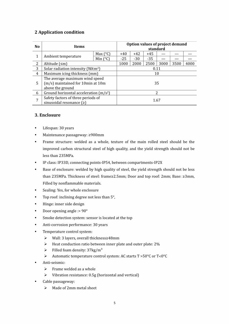
2Applicationcondition
No Items Optionvaluesofprojectdemandstandard
1 AmbienttemperatureMax(°C) +40 +42 +45 — — —Min(°C) ‐25 ‐30 ‐35 — — —
2 Altitude(≤m) 1000 2000 2500 3000 3500 40003 Solarradiationintensity(W∕cm2) 0.114 Maximumicingthickness(mm) 10
5Theaveragemaximumwindspeed(m/s)maintainedfor10minat10mabovetheground
35
6 Groundhorizontalacceleration(m/s2) 2
7Safetyfactorsofthreeperiodsofsinusoidalresonance(≥) 1.67
3.Enclosure
Lifespan:30years
Maintenancepassageway:≥900mm
Frame structure: welded as a whole, texture of the main rolled steel should be the
improved carbon structural steelofhighquality, and theyield strength shouldnotbe
lessthan235MPa.
IPclass:IP33D,connectingpoints‐IP54,betweencompartments‐IP2X
Baseofenclosure:weldedbyhighqualityofsteel,theyieldstrengthshouldnotbeless
than235MPa.Thicknessofsteel:frame≥2.5mm;Doorandtoproof:2mm;Base:≥3mm,
Filledbynonflammablematerials.
Sealing:Yes,forwholeenclosure
Toproof:incliningdegreenotlessthan5°,
Hinge:innersidedesign
Dooropeningangle:>90°
Smokedetectionsystem:sensorislocatedatthetop
Anti‐corrosionperformance:30years
Temperaturecontrolsystem:
Wall:3layers,overallthickness≥48mm
Heatconductionratiobetweeninnerplateandouterplate:2%
Filledfoamdensity:37kg/m³
Automatictemperaturecontrolsystem:ACstartsT>50°CorT˂0°C
Anti‐seismic:
Frameweldedasawhole
Vibrationresistance:0.5g(horizontalandvertical)
Cablepassageway:
Madeof2mmmetalsheet

6
Firerating:classA
Secondarychannel:tunnelmadeofmetalsheet
Lighting:
Passageway
Emergency
Maintenance
Anti‐explosionLED
Earthing:
Earthingterminal:˃Ø12
Earthingpoint:4perhouse
4.Auxiliarysystems
4.1Standardcompliance GB16796‐2009SafetyRequirementsandTestMethodforSecurityAlarmEquipment
GB10408.1‐2000 Detection for Intruder Alarm System – Part 1: Requirements for
Detectors–GeneralRequirements
GB12663‐2007GeneralTechnicalConditionsforFireAlarmControlUnit
GB4798.4‐2007 Environmental Conditions Existing in the Application of Electric and
ElectronicProducts–StationaryUseatNon‐weather‐protectedLocations
GB2423.10‐2008EnvironmentalTestingforElectricandElectronicProducts
IEC364‐4‐41StandardforProtectiveGroundingandLightningProtection
GA/T75‐94EngineeringProcedureandRequirementofSafetyandAlarmSystem
GA308‐2001AcceptanceCheckCriterionofSecurityandAlarmSystems
GA/T74‐2000SymbolsforUseinDiagramofSecurityandAlarmSystem
GB50115‐2009DesignCodeofIndustrialTelevisionSystem
GB/16677‐1996TransferEquipmentofAlarmPictureSignalthroughCable
4.2Prefabricatedsubstationenvironmentandfireprotectionmonitoring
Item Type Unit Qty Note
IndoorintelligentballBallmachineand
infraredSet 2 Simulationwithpowersupplysupport
Point‐typephotoelectric
smokedetectorJTY‐GD‐G3 Nr. 4 onefor40squares
Baseofdetector DZ‐02 Nr. 4
Manualfirealarmcall
pointJ‐SAM‐GST9121 Nr. 2 Oneforeachdoor
Fireaudibleandvisual
alarmHX‐100B Nr. 2

7
Temperature&humidity
sensorST2004 Nr. 6 485output
Temperatureand
humidityprotocol
module
ST‐WSD‐5130 Nr. 1485inputandEthernetinput;each
cabinetisprovidedwithone
Watersensor ST2003 Nr. 2 DIoutput
SF6detector(ifneed)
Detectionof
doublechamber
gas
Nr. 4 485output
SF6protocolmodule(if
need)ST‐SF6‐5130 Nr. 1
485inputandEthernetinput;each
cabinetisprovidedwithone
SF6audiblevisual
annunciator(ifneed)Horn Set 2 DO
Indoorlighting
controllerST2007E Set 1
Auxiliarysystem
equipmentbox
(purchasedbyPartyA)
Custom‐made Nr. 1
Itisofadimensionof20(thickness)×
60(width)×80(length)(CM),
equippedwithguiderail,wiring
terminals,andcabinservicepower
supply
8of10M/100MSwitches Huawei Nr. 1
Micro‐positivepressure
airconditionerTGOOD Set 2
VentilatingfanKAKU
KA2509HA2‐4Nr. 4
Environmentmonitoring
moduleST2201E Set 1
Note1:Theaboveconfigurationisonlyforreference,andthespecificconfigurationshouldbe
subjecttorelevantnationalregulationsandrequirementsoftheoperationunit.
Note2:Themanufacturerwinningthebiddingshouldtakechargeofinstallationandcommissioning
ofthesystemequipmentintheplant.

8
Part2:
HVGasInsulatedSwitchgear(GIS)
TechnicalData

9
1.Standardcompliance
IEC62271High‐voltageswitchgearandcontrolgearPart1:Commonspecifications
IEC62271‐203Gas‐insulatedmetal‐enclosedswitchgearforratedvoltagesabove52kV
IEC62271‐104Switchesforratedvoltagesof52kVandabove
IEC62271‐100High‐voltagealternating‐currentcircuit‐breakers
IEC62271‐102Alternatingcurrentdisconnectorsandearthingswitches
IEC61869‐1‐2007Instrumenttransformers‐Part1Generalrequiremnets
IEC61869‐2addionalrequirementsforcurrenttransformers
IEC60270High‐voltagetesttechniques—Partialdischargemeasurements
IEC60071‐1:2011 Insulation Co‐ordination for High‐voltage Power Transmission and
TransformationEquipment
IEC 62271‐200 AC Metal‐enclosed Switchgear and Control Gear for Rated Voltages
above3.6kVanduptoandincluding40.5kV
IEC 62271‐303 Use and handling of sulphur hexafluoride (SF6) in highvoltage
switchgearandcontrolgear
IEC60265‐2 Switches
IEC62271‐108Disconnectingcircuit‐breakers
IEC60044‐1Currenttransformer
IEC60044‐8Electroniccurrenttransformers
IEC60044‐2Voltagetransformers
IEC60044‐5Capacitorvoltagetransformers
IEC60044‐7Electronicvoltagetransformers
IEC60044‐3Combinedtransformers
IEC60099‐4Surgearresters
IEC60137Bushings
IEC61462 Insulators
IEC62271‐209 Cableconnections
IEC61639Transformerconnections
2.HVGIStechnicaldata
S/N Items Unit Data Note
I GIScommonparameter
1 Ratedvoltage kV 145
2 Ratedcurrent
Outgoingline
A
2000
Incomingline 2000
Subsection
andbuscouple2000
Mainbusbar 2000

10
S/N Items Unit Data Note
3Ratedpower‐frequencywithstandvoltage(1
min)(relatively)kV 230
4Peakvalueofratedlightningimpulse
withstandvoltage(1.2/50s)(relatively)kV 550
5 Ratedshort‐circuitbreakingcurrent kA 40
6 Ratedshort‐circuitmakingcurrent kA 100
7 Ratedshort‐timewithstandcurrent/duration kA/s 40/3
8 Ratedpeakwithstandcurrent kA 100
9Short‐timepower‐frequencywithstand
voltageofauxiliaryandcontrolcircuitskV 2
10 Radiointerferencevoltage μV ≤500
11 Noiselevel dB ≤90
12SF6gaspressure
(20°Cgaugepressure)
Circuit
breaker
chamber MPa
0.6MPa
Other
compartments0.5MPa
13 SF6gasleakagerateofeachcompartment %/Year ≤0.1
14SF6gas
humidity
Compartments
witharc
decomposition
Handover
acceptance
value
μL/L
≤150
Allowable
valueof
long‐term
operation
≤300
Compartments
withoutarc
decomposition
Handover
acceptance
value
≤250
Allowable
valueof
long‐term
operation
≤500
15 Partialdischarge
Testing
voltagekV 1.1×126/ 3
Every
compartment
pC
≤5
Everysingle
insulating
part
≤3
Bushing ≤5
Current
transformer≤5

11
S/N Items Unit Data Note
Voltage
transformer≤10
Lightning
arrester≤10
16 Powersupply
Controlcircuit V DC220
Auxiliary
circuitV AC380/220
17 Servicelife Year ≥30
18 Overhaulperiod Year ≥20
19Equipmentquality(single
space)
SF6gasquality kg 300
Totalweight kg 6000
Maximum
transportation
weight
kg 8000
Dynamicload
moves
downwards
kg 2000
Dynamicload
moves
upwards
kg 2000
20 Equipmentdimension
Overall
dimensionof
equipment
m Seedrawing
Maximum
transportation
clearanceof
equipment
m Seedrawing
Width m 0.8
21 StructuralLayout
Breaker Three‐phaseinone
tank
Bus Three‐phaseinone
tank
II Parametersofthebreaker
1 Model (providedbythe
Bidder)
2 Layoutmode Verticaltype
3 Numberoffractures 1
4 Ratedcurrent
Outgoingline
A
2000
Incomingline 2000
Subsection
andbuscouple2000
5 Maincircuitresistance μΩ 80
12
S/N Items Unit Data Note
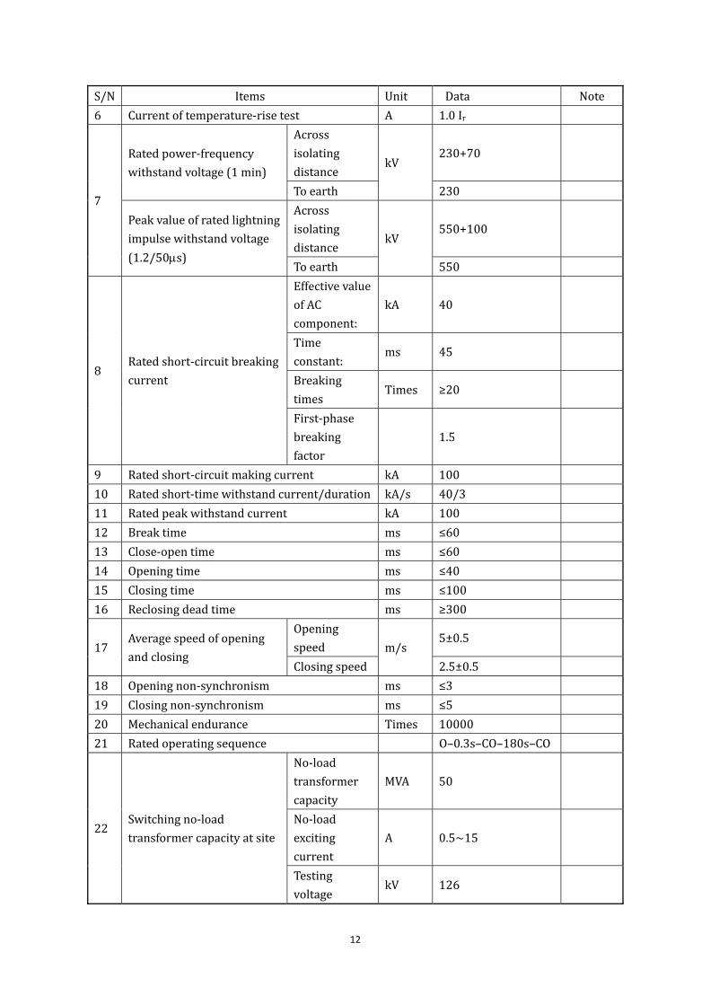
6 Currentoftemperature‐risetest A 1.0Ir
7
Ratedpower‐frequency
withstandvoltage(1min)
Across
isolating
distancekV
230+70
Toearth 230
Peakvalueofratedlightning
impulsewithstandvoltage
(1.2/50s)
Across
isolating
distancekV
550+100
Toearth 550
8Ratedshort‐circuitbreaking
current
Effectivevalue
ofAC
component:
kA 40
Time
constant:ms 45
Breaking
timesTimes ≥20
First‐phase
breaking
factor
1.5
9 Ratedshort‐circuitmakingcurrent kA 100
10 Ratedshort‐timewithstandcurrent/duration kA/s 40/3
11 Ratedpeakwithstandcurrent kA 100
12 Breaktime ms ≤60
13 Close‐opentime ms ≤60
14 Openingtime ms ≤40
15 Closingtime ms ≤100
16 Reclosingdeadtime ms ≥300
17Averagespeedofopening
andclosing
Opening
speed m/s5±0.5
Closingspeed 2.5±0.5
18 Openingnon‐synchronism ms ≤3
19 Closingnon‐synchronism ms ≤5
20 Mechanicalendurance Times 10000
21 Ratedoperatingsequence O–0.3s–CO–180s–CO
22Switchingno‐load
transformercapacityatsite
No‐load
transformer
capacity
MVA 50
No‐load
exciting
current
A 0.5~15
Testing
voltagekV 126

13
S/N Items Unit Data Note
Operating
Sequence 10×Oand10×(CO)
23Chargingcurrenttestof
fieldswitchingnon‐loadline
Testcurrent ADeterminedbythe
actuallengthofline
Testing
voltagekV 126
Testcondition
Inprinciple,theline
shouldnotbe
equippedwith
voltagereducing
devices,suchas
electricreactors,
lightningarresters,
voltagetransformers,
etc.
Operating
Sequence 10×(O‐0.3s‐CO)
24Capacitivecurrentswitching
test(laboratory)
Testcurrent A Line:31.5,cable:140
Testing
voltagekV 1.4×126/ 3
ClassC1:LC1
andCC1:
24×O;LC2
andCC2:
24×CO
ClassC2:LC1
andCC1:
48×O;LC2
andCC2:
24×Oand
24×CO
ClassC1
25Switchingcapabilityunder
theclose‐infaultcondition
L90 kA 36
L75 kA 30
L60 kA
24(theminimumarc
timeofL75is5ms
greaterthanthatof
L90)
Operating
Sequence O‐0.3s‐CO‐180s‐CO
26Out‐ofphasemakingand
breakingcapacity
breaking
currentkA 10

14
S/N Items Unit Data Note
Testing
voltagekV 2.5×126/ 3
26Out‐ofphasemakingand
breakingcapacity
Operating
Sequence
Mode1:O‐O‐O
Mode2:CO‐O‐O
27SF6gaspressure
(gaugepressure,20°C)
Rated
MPa
0.6MPa
Alarm 0.55MPa
Minimum(in
block)0.5MPa
28
Typeormodelofoperatingmechanism Spring
Operatingmode Three‐phase
mechanicallinkage
Motorvoltage V DC220
Closingoperatingpower
supply
Rated
operating
voltage
V DC220
Allowable
rangeof
operating
voltage
85%‐110%and
operationisnot
allowedbelow30%
Coilquantity
ofeachphaseNr. 1
Surgeofeach
coilA 3.3
Steady‐state
currentof
eachcoil
A DC220V,2.5A
Openingoperatingpower
supply
Rated
operating
voltage
V DC220
Allowable
rangeof
operating
voltage
65%‐110%and
operationisnot
allowedbelow30%
Coilquantity
ofeachphaseNr. 1
Surgeofeach
coilA 3.3
Steady‐state
currentof
eachcoil
A DC220V,2.5A
Heatervoltage V AC220
Powerofeach W 100W

15
S/N Items Unit Data Note
phase
Standbyauxiliarycontact
Qty. Pair
10fornormalopen
and10fornormal
closed
Breaking
capacity DC220V,2.5A
Overhaulperiod Year ≥20
Springmechanism Chargingtime s ≤20
29 Breakerquality
Overall
qualityof
breaker,
includingthe
auxiliary
equipment
kg 500
Qualityof
operating
mechanismof
eachphase
kg 150
SF6gasquality
ofeachphasekg 50
Overall
transportation
quality
kg 800
30 Transportationheight m 3.4
S/N Description UnitStandardparameter
value
31 Hoistingheight m 5
III ParametersforIsolatingSwitch
1 Type/model (providedbythe
Bidder)
2 Ratedcurrent
Outgoingline A 2000
Incomingline A 2000
Subsection
andbuscoupleA 2000
3 Maincircuitresistance μΩ(providedbythe
Bidder)
4 Currentoftemperature‐risetest A 1.1Ir
5
Ratedpower‐frequency
withstandvoltage(1min)
BreakkV
230+70
Toearth 230
Peakvalueofratedlightning
impulsewithstandvoltage
(1.2/50s)
Break
kV
550+100
Toearth 550

16
S/N Items Unit Data Note
6 Ratedshort‐timewithstandcurrent/duration kA/s 40/3
7 Ratedpeakwithstandcurrent kA 100
8 Openingandclosingtime
Openingtime
ms
(providedbythe
Bidder)
Closingtime(providedbythe
Bidder)
9Averagespeedofopening
andclosing
Opening
speedm/s
(providedbythe
Bidder)
Closingspeed(providedbythe
Bidder)
10 Mechanicalendurance Times ≥3000
11 Currentvalueofswitchingsmallcapacitance A 1
12 Currentvalueofswitchingsmallinductance A 0.5
13
Electriccurrent
transformationcapacityof
switchingbus
Switching
currentA 1600
Transforming
voltageV 10
Breaking
timesTimes 100
14
Operatingmechanism
Typeormodel Electric
Motorvoltage V AC380/220
Control
voltageV AC220
Allowed
variation
scopeof
voltage
85%~110%
Operating
mode
Three‐phase
mechanicallinkage
Standbyauxiliarycontact
Qty. Pair
10fornormalopen
and10fornormal
closed
Breaking
capacity DC220V,2.5A
IV Parametersoffastearthingswitch(FES)
1 Ratedshort‐timewithstandcurrent/duration kA/s 40/3
2 Ratedpeakwithstandcurrent kA 100
S/N Description UnitStandardparameter
value
3 Ratedshort‐circuitmakingcurrent kA 100
4 Closingtimesofratedshort‐circuitcurrent Times ≥2
5 Openingandclosingtime Openingtime ms (providedbythe

17
S/N Items Unit Data Note
Bidder)
Closingtime(providedbythe
Bidder)
6Averagespeedofopening
andclosing
Opening
speedm/s
(providedbythe
Bidder)
Closingspeed(providedbythe
Bidder)
7 Mechanicalendurance Times ≥3000
8
Switching
induction
Current
capacity
(Type
A/B)
Electromagnetic
induction
Reactive
currentA 50/80
Breaking
timesTimes 10
Induced
voltagekV 0.5/2
Electrostatic
induction
Capacitive
currentA 0.4/2
Breaking
timesTimes 10
Induced
voltagekV 3/6
9
Operatingmechanism
Typeormodel Spring
Motorvoltage V AC380/220
Control
voltageV AC220
Allowed
variation
scopeof
voltage
85%~110%
Standbyauxiliarycontact
Quantity Pair
8fornormalopen
and8fornormal
closed
Breaking
capacity DC220V,2.5A
V Parametersofmaintenancegroundingswitch
1 Ratedshort‐timewithstandcurrent/duration kA/s 40/3
2 Ratedpeakwithstandcurrent kA 100
3 Mechanicalendurance Times ≥3000
4 Operatingmechanism
Typeormodel Electric
Motorvoltage V AC380/220
Control
voltageV AC220
Allowed 85%~110%

18
S/N Items Unit Data Note
variation
scopeof
voltage
Standbyauxiliarycontact
Qty. Pair
8fornormalopen
and8fornormal
closed
Breaking
capacity DC220V,2.5A
VI ParametersforCurrentTransformer(CT)
1 Typeormodel Electromagnetictype
2 Layoutmode Internal
3
Winding1
Nominal
currentratio 400~800~1000/5A
Ratedburden 20VA
Accuracyclass
5P30(lineand
subsection)
5P20(main
transformer)
Winding2
Nominal
currentratio 400~800~1000/5A
Ratedburden 20VA
Accuracyclass
5P30(lineand
subsection)
5P20(main
transformer)
Winding3
Nominal
currentratio 400~800~1000/5A
Ratedburden 20VA
Accuracyclass
5P30(lineand
subsection)
5P20(main
transformer)
Winding4
Nominal
currentratio 400~800~1000/5A
Ratedburden 20VA
Accuracyclass 0.5
Winding5
Nominal
currentratio 400~800~1000/5A
Ratedburden 20VA
Accuracyclass 0.2S
VII Parametersforvoltagetransformer(VT)

19
S/N Items Unit Data Note
1 Typeormodel Electromagnetictype
2 Ratedvoltageratio 110 0.1 0.1
0.13 3 3
3 Accuracyclass 0.2/0.5/3P,
4 Wiringgroup Y/Y/Y/
5 Three‐phaseimbalance V 1
61minpowerfrequencywithstandvoltageof
lowvoltagewindingkV 3
7 Ratedvoltagefactor
1.2×rated
continuous,
1.5×rated30S
VIII Lightningarresterparameters
1 Ratedvoltage kV 108
2 Continuousoperatingvoltage kV 84
3 Nominaldischargecurrent(8/20μs) kA 10
4Residualvoltageatsteepimpulsecurrent
(1/10μs)kV 315
5Residualvoltageunderlightningimpulse
current(8/20μs)kV 281
6Residualvoltageatswitchingimpulsecurrent
(30/60μs)kV 239
7 DC1mAreferencevoltage kV ≥157
8Leakcurrentat75%ofDC1mAreference
voltageμA ≤50
9Power‐frequencyreferencecurrent(effective
value)kV ≥108
10 Power‐frequencyreferencecurrent(peak) mA 2
11 Continuouscurrent
Fullcurrent mA 0.85
Resistive
current μA 250
12Longdurationimpulse
withstandcurrent
Linedischarge
class 2
Impactof
rectangular
wavecurrent
impact
A 800
13 4/10μslargeimpulsewithstandcurrent kA 100
14 Operatingload Pass
15Characteristicsofpowerfrequencyvoltage
withstandduration
1.2Ur*0.2s
1.15Ur*1.1s
1.1Ur*10s

20
S/N Items Unit Data Note
1.0Ur*20min
16Absorptioncapabilityofkilovoltnominal
voltagekJ/kV ≥7.25
17 Pressurereleasecapacity kA/s 40/0.2
IXBushingparameters(thisitemiscomposedofinletandoutletcables,itisnotequipped
withbushing)
1 Umbrellaskirttype Largeandsmall
umbrella
2 Material Porcelain Orepoxy
3 Ratedcurrent A 2000
4 Ratedshort‐timewithstandcurrent/duration kA/s 40/3
5 Ratedpeakwithstandcurrent kA 100
6Ratedpower‐frequencywithstandvoltage(1
min)(relatively)kV 230
7Peakvalueofratedlightningimpulse
withstandvoltage(1.2/50s)(relatively)kV 550
8 Creepagedistance mm
3150
(whentheaverage
diameterisbetween
300mm(included)
and500mm
(included),thefigure
shouldmultipleby
1.1;whenthe
averagediameter
isgreaterthan
500mm,thefigure
shouldmultipleby
1.2)
ForDL
standard
9 Dryacingdistance mm ≥900
10 S/P ≥0.9
11 Terminalstaticload
Longitudinal
N
1250
Horizontal 750
Vertical 1000
Safety
coefficient
Staticstate:2.75;
dynamicstate:1.7
12Minimumclearancebetweenphasesof
electrifiedpartofmetalatbushingtopmm ≥1000
X Parametersofepoxycastinginsulator
1 Safetycoefficient Greaterthan3times
ofdesignvoltage
2 Leakagecurrentunder2timesofnominal μA 50

21
S/N Items Unit Data Note
phase‐phasevoltage
3Themaximumfielddensityunder1.1times
ofnominalphase‐voltagekV/mm ≤1.5
XI Busparameters
1 Material Aluminum
2 Ratedcurrent A 2000
3 Ratedshort‐timewithstandcurrent/duration kA/s 40/3
4 Ratedpeakwithstandcurrent kA 100
5Conductordiameter(innerdiameter/outer
diameter)mm (30/60)
XII Shellparameters
1 Material Aluminumalloy
2 Breakdownpressureforshell
Castaluminumand
aluminumalloy:5
timesofthedesign
voltage;
Weldedaluminum
shellsandsteel
shells:3timesofthe
designvoltage
3 Temperaturerise
Testcurrent A 1.0Ir
Positions
contactableK ≤30
Positionsmay
becontactableK ≤40
Positions
cannotbe
contactable
K 65
4Resistanceofcasingtobe
burn‐through
Current kA 40
Time s 0.3
5 Erectionofexplosion‐proofmembrane Yes
XIII Parametersofexpansionjoint
1 Material Stainlesssteel
2 Servicelife ≥30yearsor10,000
timesofexpansion
XIV ParametersforSF6Gas
1 Humidity μg/g ≤8
2 Purity % ≥99.8

22
Part3:
110kVNeutralPointCompleteEquipmentforServiceTransformer
TechnicalData

23
1. Standardcompliance
StandardNo. DescriptionofStandard
IEC60038 StandardVoltage
GB1985‐89 ACHigh‐voltageIsolatingSwitchandEarthingSwitches
GB4585.2 ACsystemapplieshigh‐voltageinsulatorartificialpollutiontest,curedlayer
method
DL/T620‐1997 OvervoltageProtectionandInsulationCoordinationforACElectrical
Installations
GB1208 Currenttransformer
IEC60071‐1:2011 InsulationCo‐ordinationforHigh‐voltagePowerTransmissionand
TransformationEquipment
GB/T775.3‐1987TestMethodforInsulators
GB5582‐1993 ExternalInsulationPollutionClassesofHigh‐voltageElectricPower
Equipment
GB/T7354‐1987 MeasurementofPartialDischarge
GB/T11604
‐1989
RadioInterferenceTestforHigh‐voltageElectricalEquipment
IEC60060:2011 High‐voltageTestTechniques
GB11032‐2000 Metal‐oxideSurgeArresterswithoutGapsforA.C.Systems
GB50150‐2006
StandardforHand‐overTestofElectricEquipmentElectricEquipment
InstallationEngineering
GB763 HeatingofACHigh‐voltageApparatusunderLongRuns
GB191‐1990 Package,StorageandTransportationIdentificationMarks
GB311.1‐‐1997 Insulation Co‐ordination for High‐voltage Power Transmission andTransformationEquipment
GB2706 TestingMethodsforDynamicandThermalStabilityTestofACHigh‐voltage
ElectricalApparatus
GB5582 External Insulation Pollution Classes of High‐voltage Electric Power
Equipment
GB/T13540 Anti‐seismicCharacteristicTestforHigh‐voltageSwitchgear
DL/T620 Overvoltage Protection and Insulation Coordination for AC Electrical
Installations
2Technicaldata
2.1Operationoverviewofsystem

24
Nominalvoltageofsystem:110kV
Maximumvoltageofsystem:126kV
Systemfrequency:50Hz,60Hz
Neutralpointoperationmodeofsystem: Groundingthroughisolatingswitches
2.2Technicaldata Equipment name and model: neutral point protection device of transformer,
JY‐JXC‐110
Ratedvoltageoftransformer:110kV
Insulationleveloftransformerneutralpoint:
1.2/50µSLightningimpulsefullwave(peakvalue):325kV
1minpower‐frequencywithstandvoltage(effectivevalue):140kV
Typeoftheneutralpointlightningarrester:YH1.5W‐72/186W
1.Ratedfrequencyoflightningarrester: 50Hz
2.Ratedvoltageoflightningarrester: 72kV
3.Continuousoperatingvoltageoflightningarrester: 58kV
4.Nominaldischargecurrent: 1.5kA
5.Protectioncharacteristicofthelightningarrester
Residualvoltageundersteepcurrentsurge(peakvalue): ≤kV
Residualvoltageatlightningimpulsecurrent(peakvalue): ≤186kV
Residualvoltageatswitchingimpulsecurrent(peakvalue): ≤174kV
6.DC1mAreferencevoltage: ≮103kV
7.Leakcurrentat75%ofDC1mAreferencevoltage:≯50A8.Frequency referencevoltage (frequency referencecurrentnoted)72kV(resistive
currentpeakvalue1mA)
9.Highcurrentimpulsewithstand: 10kA (Residual voltage during high current
impulsecanbeprovided)
10.Pressurereleasecapacity
Largecurrent: 20kA
Smallcurrent: 400A
11.Radiointerferencevoltageisnotgreaterthan: 500V12.Partialdischargeisnotgreaterthan: 10pC
Technicalparametersofelectricalequipmentrequiredbythedischargegapinmain
neutralpoint: (Determinedbyparametersofneutralpoint lightningarresterby the
Supplier)
Gapratedvoltage:83kV±5%
Scopeofgapelectrodedistance:50mm~300mm(adjustable)
Electrodeconfigurationmode:sealed
Electrodetype:Sphericalgapmaterial:electroplatingsteelball
Isolatingswitch:630A,electricaloperatingmechanism,auxiliarycontacts(6normally
opencontactsand6normallyclosedcontacts)(silvering)
Current transformeratneutralpointsofmain transformer:150/5Adoublewinding
5P30/0,.5(supplywithmaintransformer,excludedinthissupply)
Integrate isolating switch, discharge gap, lightning arrester and gap current
transformer,andsupplyincompleteset.

25
Basematerial:hotgalvanizedsteel;Fixingmode:boltfixing,withequipmentsupport
suppliedincompletesetbythesupplier.
Insulating articles and supporting pieces have moisture‐proof performance, to
maintainthedielectricstrengthunchanged.Theequipment,ofsoundsealing,meets
long‐termoutdooroperationconditions,
Theconductorsectionandtypeconnectingtothetransformerneutralpointshallbe
determinedbytheDemander.
Provide factory documents such as inspection report and quality certificate during
productssupplying
Install current transformerat gap side:LJW1‐10200/5A0.5/10P15,15/15VA, type:
epoxyresincastfully‐enclosedsupporting10kV

26
Part4: 40.5kVHouseTechnicalData
27
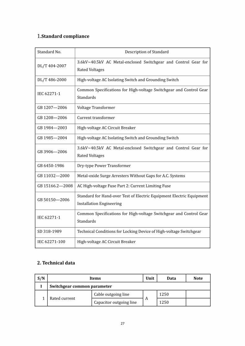
1.Standardcompliance
StandardNo. DescriptionofStandard
DL/T404‐20073.6kV~40.5kV AC Metal‐enclosed Switchgear and Control Gear for
RatedVoltages
DL/T486‐2000 High‐voltageACIsolatingSwitchandGroundingSwitch
IEC62271‐1CommonSpecifications forHigh‐voltageSwitchgearandControlGear
Standards
GB1207—2006 VoltageTransformer
GB1208—2006 Currenttransformer
GB1984—2003 High‐voltageACCircuitBreaker
GB1985—2004 High‐voltageACIsolatingSwitchandGroundingSwitch
GB3906—20063.6kV~40.5kV AC Metal‐enclosed Switchgear and Control Gear for
RatedVoltages
GB6450‐1986 Dry‐typePowerTransformer
GB11032—2000 Metal‐oxideSurgeArrestersWithoutGapsforA.C.Systems
GB15166.2—2008 ACHigh‐voltageFusePart2:CurrentLimitingFuse
GB50150—2006StandardforHand‐overTestofElectricEquipmentElectricEquipment
InstallationEngineering
IEC62271‐1CommonSpecifications forHigh‐voltageSwitchgearandControlGear
Standards
SD318‐1989 TechnicalConditionsforLockingDeviceofHigh‐voltageSwitchgear
IEC62271‐100 High‐voltageACCircuitBreaker
2.Technicaldata
S/N Items Unit Data Note
I Switchgearcommonparameter
1 RatedcurrentCableoutgoingline
A1250
Capacitoroutgoingline 1250

28
S/N Items Unit Data Note
Groundingtransformeroutgoingline
1250
Busbarequipment 1250
2 Powersupply
Controlcircuit VDC220/DC110
Auxiliarycircuit V AC380/AC220
3 Arcduration S 0.3~0.5
4 Equipmentdimension
Overalldimensionofsingleswitchgear(Length Width Height)
mm (1600×600×2350)
Consultusfordetails
II Parametersofthebreaker
1Switchingno‐loadtransformercapacityatsite
No‐loadtransformercapacity MVA 10/20/31.5
No‐loadexcitingcurrent A 0.5~15
2Capacitivecurrentswitchingtest(Laboratory)
ClassC1: CC1:24×O, CC2:24×CO;BC1:24×O,BC2:24×CO
ClassC1/C2 ClassC2:CC1:48×O, CC2:24×Oand24×CO; BC1:24×O, BC2:80×CO
3
Motorvoltage V AC380/220
Closingoperatingpowersupply
Ratedoperatingvoltage VDC220/DC110
Steady‐statecurrentofeachcoil A
DC220V,2.5AorDC110V,5A
Openingoperatingpowersupply
Ratedoperatingvoltage V DC220/DC110
Steady‐statecurrentofeachcoil A
DC220V,2.5AorDC110V,5A
Quantityofprotectioncoil Nr.Providedbyprojectcompany
Auxiliarycontact Breakingcapacity DC220V,2.5AorDC110V,5A
III Parametersofearthingswitch
1Operatingmechanism Type
Electricandmanual

29
S/N Items Unit Data Note
Motorvoltage V AC380/220
Auxiliarycontact Breakingcapacity DC220V,2.5AorDC110V,5A
IV Parametersforcurrenttransformer
1
Winding1
Nominalcurrentratio 200~1250/1(5)
Ratedburden VA 15/20/30
Accuracyclass 10P10/10P20
Winding2
Nominalcurrentratio 200~1250/1(5)
Ratedburden VA 15/20/30
Accuracyclass 10P10/10P20
Winding3
Nominalcurrentratio 200~1250/1(5)
Ratedburden VA 15/20/30
Accuracyclass 0.5
Winding4
Nominalcurrentratio 200~1250/1(5)
Ratedburden VA 15/20/30
Accuracyclass 0.2S
V Parametersforvoltagetransformer
1 Ratedcapacity VA 20/50/100
VI Fuseparameter
1 Fusetype RNP‐0.5
2 Ratecurrentoffuse A 0.5A
3 Ratedshort‐circuitbreakingcurrentforfuse kA 31.5kA
VIII Parametersofbusbar
1 Ratedcurrent A 2000A

30
Part5: 40.5kVArcSuppressionCoil
House TechnicalData

31
1. Standardcompliance
StandardNo. DescriptionofStandard
IEC60071‐1:2011InsulationCo‐ordinationforHigh‐voltagePowerTransmissionand
TransformationEquipment
IEC60060 High‐voltageTestTechniques
GB8287.1 High‐voltagePillarPorcelainInsulator
GB50150StandardforHand‐overTestofElectricEquipmentElectricEquipment
InstallationEngineering
IEC62271‐102 AlternatingCurrentDisconnectorsandEarthingSwitches
GB10230 On‐loadTap‐changer
GB11032 Metal‐oxideSurgeArresterswithoutGapsforA.C.Systems
IEC62271‐200Metal‐enclosedSwitchgearforAlternatingCurrentatRatedVoltagesof
Between1and52kV
GB1094.1~5 PowerTransformer
GB1094.3 InsulationLevels,DielectricTestsandExternalClearancesinAir
GB1094.11 Dry‐typePowerTransformer
GB10229 Reactor
GB7328 DeterminationofPowerTransformerandReactorSoundLevels
GB7354 PartialDischargeMeasurements
GB7449GuidetotheLightningImpulseandSwitchingImpulseTestingofPower
TransformersandReactors
GB/T13540 Anti‐seismicCharacteristicTest
GB/T14549 QualityofElectricEnergy‐HarmonicsinPublicSupplyNetwork
GB/T17626.2~12 ElectromagneticCompatibilityTestingandMeasurementTechniques
DL/T1057TechnicalSpecificationsofAutomaticTrackingandCompensationand
ArcSuppressionCoilDevice
DL/T620OvervoltageProtectionandInsulationCoordinationforACElectrical
Installations
IEC62271‐103: SwitchesforRatedVoltagesabove1andLessThan52kV
IEC60255 MeasurementRelayandProtectionUnit
IEC60282‐2 HighVoltageFuses
IEC61869‐2 CurrentTransformers
IEC61869‐3 VoltageTransformers
IEC60529 DefiningtheProtectionIndicesProvidedbytheEnclosures
IEC62271‐206: VoltagePresenceIndicatingSystems

32
Q/GDW168RegulationsofCondition‐basedMaintenance&TestforElectric
Equipment
SGCC TechnicalStandardfor10kV~66kVArcSuppressionCoilDevices
GJDWS[2004]
No.61Anti‐accidentMeasuresfor10kV~66kVArcSuppressionCoilDevices
GJDWS[2006]
No.51
InstructionsonTechnicalTransformationofArcSuppressionCoil
Devices
SGCC[2005] TechnicalStandardfor10kV~66kVArcSuppressionCoilDevices
2.Technicaldata
S/N Items Unit Value Note
1 Operatingconditions Indoor
2 Unitpackage
Ratedvoltage kV 40.5
Ratedfrequency Hz 50,60
Insulationlevel kV
Powerfrequency(1min)withstandvoltage(effective):85kV
Lightningfull‐waveimpulsewithstandvoltage(peakvalue):200kV
Ratedcapacityofarcsuppressioncoil
kVA 1800
Ratedcurrentofarcsuppressioncoil
A 0~81
Measuringerrorofcapacitancecurrent
% <±2
Residualcurrent A ≤5

33
S/N Items Unit Value Note
Neutralpointdisplacementvoltageofthegridatmountingpoint
≯15%ofnominalphasevoltage
Arrivaltimeofgroundcompensation
ms Lessthan10μs s
Incoming&outgoingmodes
Cable
3 Extinctioncoil
Ratedcapacity kVA 1800
Ratedcurrent A 0~81
Adjustingmode Phasecontrol
Regulatingrange 50~100%
Linearityrangeof
volt‐ampere
characteristics
0~110%UN
TypeofInsulation Drytype(ClassF)
Insulationlevel kV
Powerfrequency(1min)withstandvoltage(effective):85kV
Lightningfull‐waveimpulsewithstandvoltage(peakvalue):200kV
Temperature‐riselimit
(WorkingCondition)
K
Topoil
Nottoexceed95Kunderratedoperationconditions.
HVwinding
Fueltank,ironcoreandsurfaceofmetal

34
S/N Items Unit Value Note
structure
Windinghotpoint
Continuousoperationtimeofratedcurrent(min.)
hour 2
Coolingmode
Self‐cooling(equippedwithtemperaturedisplay,controlandtele‐transmissionfunctions)
Externalinsulationcreepagedistance
mm/kV ≥20(indoor)
≥20(indoor)
Partialdischarge pC <3.6
Noise dB0.3mawayfromthetransformerbody≤50dB
Electricallifeofswitchcontactontapswitch
Notlessthan200,000timesofmovement
Mechanicallifeswitchcontactontapswitch
Notlessthan800,000timesofmovement
4Control
Device
Type
Highreliability,highdegreeofintegration,dedicatedcomputerorprogrammingcontrollerforindustrialusewithmodularstructure.
Ratedvoltage VDC220VorDC110V,reliableworkingvoltagerange75%~115%
Measuringerrorofcapacitancecurrent
% ‐2~+2
35
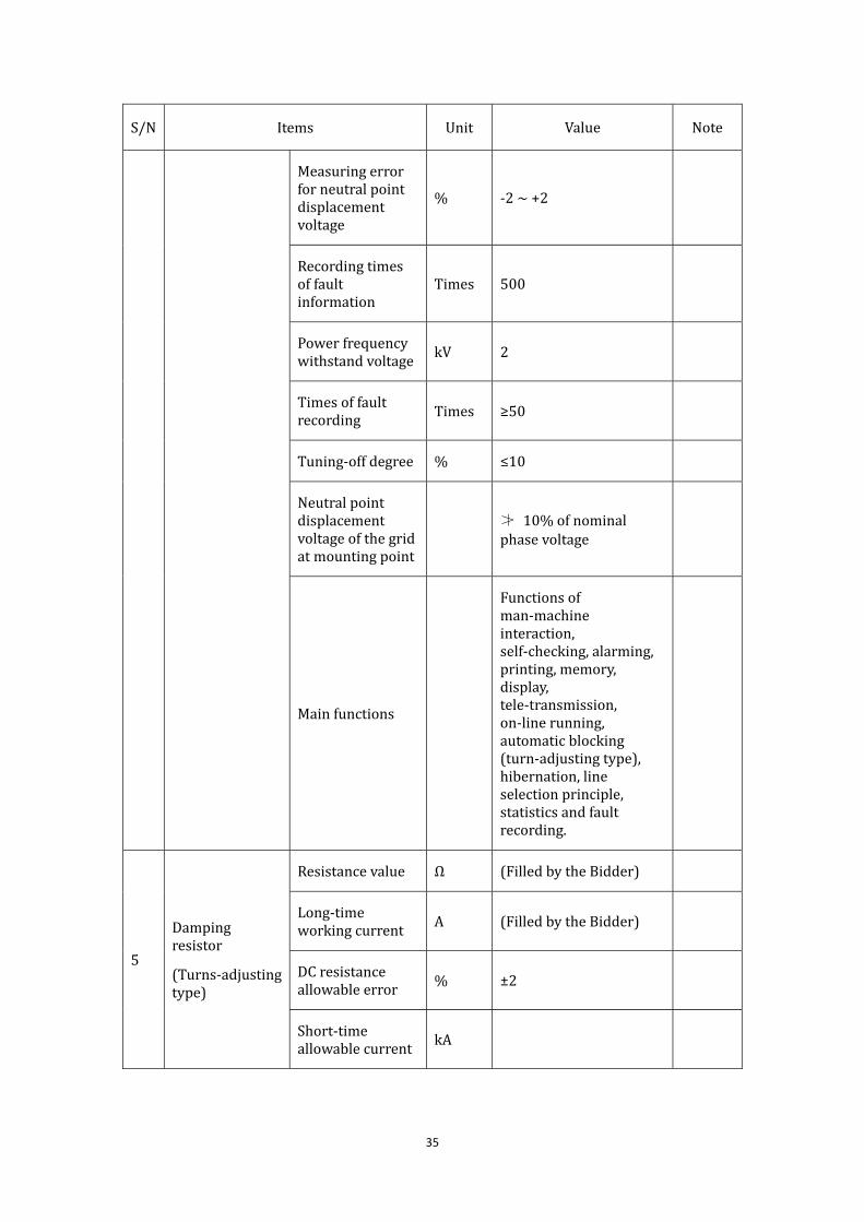
S/N Items Unit Value Note
Measuringerrorforneutralpointdisplacementvoltage
% ‐2~+2
Recordingtimesoffaultinformation
Times 500
Powerfrequencywithstandvoltage
kV 2
Timesoffaultrecording Times ≥50
Tuning‐offdegree % ≤10
Neutralpointdisplacementvoltageofthegridatmountingpoint
≯ 10%ofnominalphasevoltage
Mainfunctions
Functionsofman‐machineinteraction,self‐checking,alarming,printing,memory,display,tele‐transmission,on‐linerunning,automaticblocking(turn‐adjustingtype),hibernation,lineselectionprinciple,statisticsandfaultrecording.
5
Dampingresistor
(Turns‐adjustingtype)
Resistancevalue Ω (FilledbytheBidder)
Long‐timeworkingcurrent
A (FilledbytheBidder)
DCresistanceallowableerror % ±2
Short‐timeallowablecurrent
kA

36
S/N Items Unit Value Note
Earthinsulation MΩ >100
6 Lineselectiondevice(options)
Type
Ifturn‐adjustingtypeisapplied,
Paralleledmediumresistanceshallbeselected.
7 Boxoutercover Protectiongrade NotlessthanIP20(indoor)

37
Part6: 17.5kVHouse TechnicalData

38
1. Standardcompliance
IEC62271‐1:Clausescommontohighvoltageswitchgear
IEC62271‐100:Highvoltagealternatingcurrentcircuit‐breakers
IEC62271‐102:Alternatingcurrentdisconnectorsandearthingswitches
IEC62271‐103:Switchesforratedvoltagesabove1andlessthan52kV
IEC62271‐200:Metal‐enclosedswitchgearforalternatingcurrentatratedvoltagesof
between1and52kV
IEC60282‐2:Highvoltagefuses
IEC60255:Measurementrelayandprotectionunit
IEC61869‐2:Currenttransformers
IEC61869‐3:Voltagetransformers
IEC60529:Definingtheprotectionindicesprovidedbytheenclosures
IEC62271‐206:VoltagePresenceIndicatingSystems(highvoltage
2Technicaldata
No Items Unit Data Note
I Switchgearcommonparameter
1 StructuralType Trolleytype
2 Ratedvoltage kV 17.5
3 Ratedfrequency Hz 50,60
4 Ratedcurrent A 630‐3150
5 Temperaturerisetest 1.0Ir
6 Ratedpower‐frequencywithstandvoltage(1min) kV 38
7 Peakvalueofratedlightningimpulsewithstandvoltage(1.2/50s) kV 95
8 Ratedshort‐circuitbreakingcurrent kA 31.5
9 Ratedshort‐circuitmakingcurrent(50Hz) kA 80 82at60Hz
10 Ratedshort‐timewithstandcurrent/duration kA/s 31.5/3
11 Ratedpeakwithstandcurrent(50Hz) kA 8082at60Hz
12 Short‐timepower‐frequencywithstandvoltageofauxiliaryandcontrolcircuits kV 2
13 Partialdischarge
Testingvoltage kV 1.1×12/ 3
Singleinsulatingpart pC ≤3
39
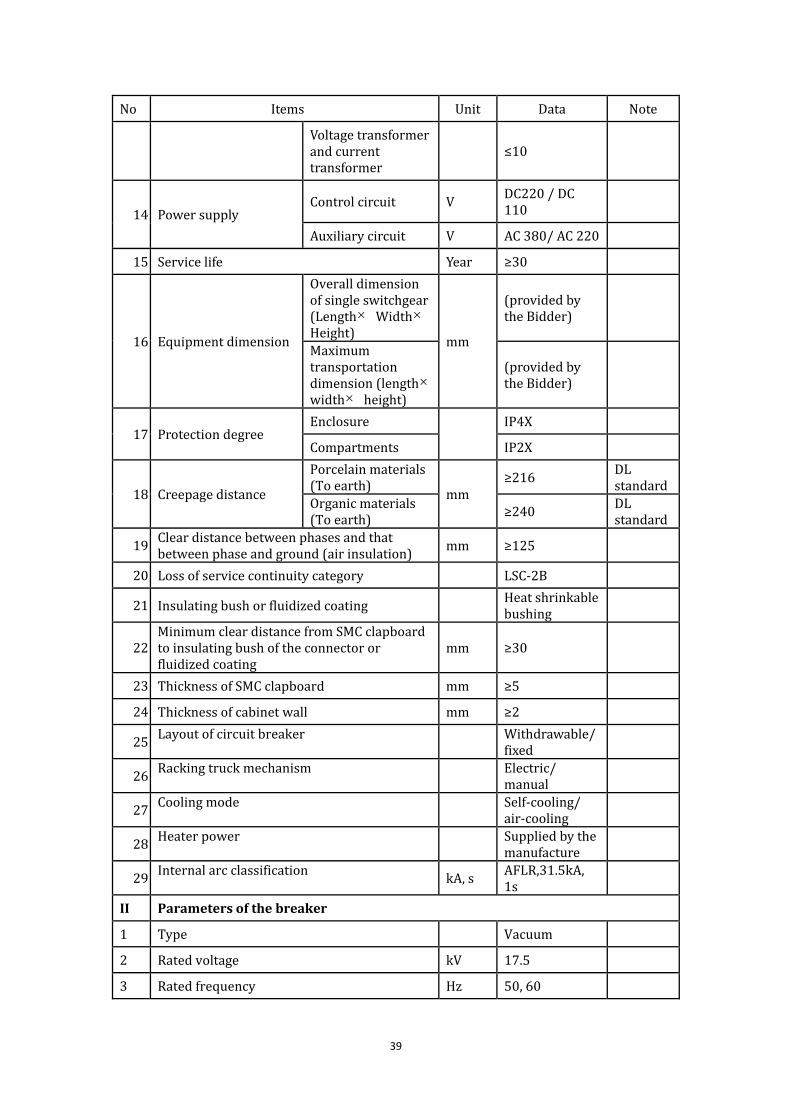
No Items Unit Data Note
Voltagetransformerandcurrenttransformer
≤10
14 PowersupplyControlcircuit V
DC220/DC110
Auxiliarycircuit V AC380/AC220
15 Servicelife Year ≥30
16 Equipmentdimension
Overalldimensionofsingleswitchgear(Length Width Height)
mm
(providedbytheBidder)
Maximumtransportationdimension(length width height)
(providedbytheBidder)
17 ProtectiondegreeEnclosure
IP4X
Compartments IP2X
18 Creepagedistance
Porcelainmaterials(Toearth)
mm≥216
DLstandard
Organicmaterials(Toearth) ≥240
DLstandard
19 Cleardistancebetweenphasesandthatbetweenphaseandground(airinsulation) mm ≥125
20 Lossofservicecontinuitycategory LSC‐2B
21 Insulatingbushorfluidizedcoating Heatshrinkablebushing
22 MinimumcleardistancefromSMCclapboardtoinsulatingbushoftheconnectororfluidizedcoating
mm ≥30
23 ThicknessofSMCclapboard mm ≥5
24 Thicknessofcabinetwall mm ≥2
25 Layoutofcircuitbreaker Withdrawable/
fixed
26 Rackingtruckmechanism Electric/
manual
27 Coolingmode Self‐cooling/
air‐cooling
28 Heaterpower Suppliedbythe
manufacture
29 Internalarcclassification kA,s AFLR,31.5kA,
1s
II Parametersofthebreaker
1 Type Vacuum
2 Ratedvoltage kV 17.5
3 Ratedfrequency Hz 50,60

40
No Items Unit Data Note
4 Ratedcurrent A 630‐3150
5 Maincircuitresistance μΩ(providedbytheBidder)
6 Temperaturerisetest 1.0Ir
7
Ratedpower‐frequencywithstandvoltage(1min) kV 38
Peakvalueofratedlightningimpulsewithstandvoltage(1.2/50s)
kV 95
8Ratedshort‐circuitbreakingcurrent
EffectivevalueofACcomponent:
kA 31.5
Timeconstant: ms 45
Electricendurance Times E2
First‐phasebreakingfactor 1.5
9 Ratedshort‐circuitmakingcurrent(50Hz) kA 80 82(60Hz)
10 Ratedshort‐timewithstandcurrent/duration kA/s 31.5/3
11 Ratedpeakwithstandcurrent(50HZ) kA 80 82(60Hz)
12 Breaktime ms 60
13 Timeforcontactclosing ms 2
14 Openingtime ms 45
15 Closingtime ms 70
17 Reclosingdeadtime ms 300
18Averagespeedofopeningandclosing
Openingspeedm/s
Closingspeed
19 Openingnon‐synchronism ms 2
20 Closingnon‐synchronism ms 2
21 Mechanicalendurance M2 10000
times
22 Ratedoperatingsequence
Feeder:O–0.3s–CO–180s–CO
Powerreceivingandsubsection:O–180s–CO–180s–CO
23 Short‐timepowerfrequencywithstandvoltageofauxiliaryandcontrolcircuits
kV 2

41
No Items Unit Data Note
24 Breakingtestofout‐phasegroundingfault
3 /Doubleratedshort‐circuitbreakingcurrent
25Capacitivecurrentswitchingtest(Laboratory)
Testcurrent ACable:25,Capacitorbank:≥400
Testingvoltage kV 1.4×12/ 3
ClassC1:CC1:24×O,CC2:24×CO;BC1:24×O,BC2:24×CO
ClassC2 ClassC2:CC1:48×O,CC2:24×Oand24×CO; BC1:24×O,BC2:80×CO
26
Typeormodelofoperatingmechanism Spring
Operatingmode Three‐phasemechanicallinkage
CBchargingmotorvoltage V DC220
Closingoperatingpowersupply
Ratedoperatingvoltage
V DC220
Allowablerangeofoperatingvoltage
85%~110%,30%isnotallowedtobeoperated
Coilquantityofeachphase
Nr. 1
Surgeofeachcoil A
Steady‐statecurrentofeachcoil A DC220V,2.5A
Openingoperatingpowersupply
Ratedoperatingvoltage
V DC220
Allowablerangeofoperatingvoltage
65%~110%,30%isnotallowedtobeoperated
Coilquantityofeachphase Nr. 1
Surgecurrentofeachcoil A
(providedbytheBidder)

42
No Items Unit Data Note
Steady‐statecurrentofeachcoil
A DC220V,2.5A
Standbyauxiliarycontact
Quantity Pair10fornormalopenand10fornormalclosed
Breakingcapacity DC220V,2.5A
Overhaulperiod Year ≥15
Energystoragetimeofspringmechanism s ≤20
27Vacuumdegreeofvacuumarcextinguishchamber Pa ≤1.33×10‐3
III ParametersofIsolatingSwitch(ifany)
1 Type (providedbytheBidder)
2 Ratedcurrent A 630‐3150
3 Maincircuitresistance μΩ
4 Currentoftemperature‐risetest A 1.0Ir
5
Ratedpower‐frequencywithstandvoltage(1min)
Acrossisolatingdistance
kV48
Toearth 42
Peakvalueofratedlightningimpulsewithstandvoltage(1.2/50s)
Acrossisolatingdistance
kV85
Toearth 75
6 Ratedshort‐timewithstandcurrent/duration kA/s 40/4(31.5/4)
7 Ratedpeakwithstandcurrent kA 100/80
8Openingandclosingtime
Openingtime
ms
(providedbytheBidder)
Closingtime(providedbytheBidder)
9 Averagespeedofopeningandclosing
Openingspeed
m/s
(providedbytheBidder)
Closingspeed (providedbytheBidder)
10 Breakingcapacitancecurrent A 0.5
11 Breakinginductivecurrent A 0.5
12 Mechanicalendurance Times ≥3000
13 OperatingmechanismTypeormodel Manual
Motorvoltage V

43
No Items Unit Data Note
Controlvoltage V DC220
Allowedvariationscopeofvoltage 85%~110%
Operatingmode Three‐phasemechanicallinkage
Standbyauxiliarycontact
Quantity Pair 10NO10NC
Breakingcapacity DC220V,2.5A
IV Parametersforearthingswitch
1 Ratedshort‐timewithstandcurrent/duration kA/s 31.5/4
2 Ratedpeakwithstandcurrent kA 100/80
3 Ratedmakingcurrent kA 100/80
4 Ratedon‐offfrequency Times 2
5 Mechanicalendurance Times ≥3000
6
Operatingmechanism
Type ManualMotoroptional
Motorvoltage V AC380/220
Controlvoltage V DC220
Allowedvariationscopeofvoltage
85%~110%
Operatingmode Three‐phasemechanicallinkage
Standbyauxiliarycontact
Quantity Pair8fornormalopenand8fornormalclosed
Breakingcapacity DC220V,2.5A
V ParametersofCurrentTransformer(CT)
1 Type Drytypeandelectromagnetictype
2
Winding1
Nominalcurrentratio
Intermsof
primary
drawings
Ratedburden VA 20
Accuracyclass 0.2S
Winding2Nominalcurrentratio
Intermsof
primary
drawings

44
No Items Unit Data Note
Ratedburden VA 20
Accuracyclass 0.5
Winding3
Nominalcurrentratio
Intermsof
primary
drawings
Ratedburden VA 30
Accuracyclass 10P20
Winding4
Nominalcurrentratio
Intermsof
primary
drawings
Ratedburden VA 30
Accuracyclass 10P20
VII Parameterofvoltagetransformer(VT)andfuse
1 Type Drytypeandelectromagnetictype
2 Ratedvoltageratio 10/√3:0.1/√3:0.1/√3:0.1/3
3 Accuracyclass 0.2/0.5/3P
4 Connectiongrade Yn/yn/yn/
5 Ratedcapacity VA 10/20/30
6 Three‐phaseimbalance V 1
7 1minpowerfrequencywithstandvoltageoflowvoltagewinding
kV 2
8 Ratedvoltagefactor 1.2×ratedcontinuous,1.9×rated8h
9 Fusetype
Providedby
project
company
10 Ratecurrentoffuse A
Providedby
project
company
11 Ratedshort‐circuitbreakingcurrentforfuse kA
Providedby
project
company
VIII Lightningarresterparameters
1 Type HY5W‐XX

45
No Items Unit Data Note
2 Ratedvoltage kV 17.5
3 Continuousoperatingvoltage kV 17.5
4 Nominaldischargecurrent kA 5
5Residualvoltagepeakatsteepimpulsecurrent(5kA,1/3μs) kV ≤51.8
6 Residualvoltagepeakunderlightningimpulsecurrent(5kA,8/20μs) kV ≤45
7Residualvoltagepeakatswitchingimpulsecurrent(250A,30/60μs) kV ≤38.3
8 DC1mAreferencevoltage kV ≥24
9Leakcurrentat75%ofDC1mAreferencevoltage μA
(providedbytheBidder)
10 Power‐frequencyreferencecurrent(effectivevalue)
kV (providedbytheBidder)
11 Power‐frequencyreferencecurrent(peak) mA(providedbytheBidder)
12 Continuouscurrent
Fullcurrent mA(providedbytheBidder)
Resistivecurrent μA (providedbytheBidder)
13 Longdurationimpulsewithstandcurrent A400(peakvalue)
14 4/10μslargeimpulsewithstandcurrent kA 65(peakvalue)
15 Operatingload (providedbytheBidder)
16Characteristicsofpowerfrequencyvoltagewithstandduration
(providedbytheBidder)
17Absorptioncapabilityofkilovoltnominalvoltage kJ/kV
(providedbytheBidder)
18 Pressurereleasecapacity kA/s 25/0.2
IX Parametersforbusbar
1 Material Copper
2 Ratedcurrent A 4000
3 Ratedshort‐timewithstandcurrent/duration kA/s 40/3
4 Ratedpeakwithstandcurrent kA 100
5 Sectionofconductor mm2Providedbysupplier
X Servicetransformer

46
No Items Unit Data Note
1 Type Drytype
2 Capacity
Providedby
project
company
3 Ratedvoltageratio
Providedby
project
company
4 Impedance
Providedby
project
company
5 Connectionsymbol
Providedby
project
company
6 Loss
Providedby
project
company

47
Part7:
17.5kVCompensationHouse
TechnicalData

48
1.Standardcompliance
IEC60071‐1:2011InsulationCo‐ordinationforHigh‐voltagePowerTransmissionand
TransformationEquipment
GB1208CurrentTransformer
GB1985ACHigh‐voltageIsolatingSwitchesandEarthingSwitches
GB7354MeasurementofPartialDischarge
GB8287 High‐voltagePillarPorcelainInsulator
GB11032 Metal‐oxideSurgeArresterswithoutGapsforA.C.Systems
GB50060 DesignCodeforHigh‐voltageElectricalInstallation(3~110kV)
GB 50227 Standard Design Code for Parallel‐connected Capacitor Package shall be
applicabletotheunit
GB50260DesignCodeofSeismicofElectricalInstallations
GB15166.5 ACHigh‐voltageFuseinParallelConnectionwithExternalProtectiveFuse
oftheCapacitor
GB/T 5582 External Insulation Pollution Classes of High‐voltage Electric Power
Equipment
GB/T 11024 Parallel Capacitor for AC Electric Power System with Nominal Voltage
over1kV
GB/T16927.1~16927.2 High‐voltageTestingTechniques
3Technicaldata
S/N Items Unit Data Note
I Parameterofcapacitor
1 Devicetype TBB10‐4800/400‐AKW
2 Ratedvoltage kV 10
3 Ratedcapacity kVAR 4800

49
S/N Items Unit Data Note
4 Ratedreactanceratio % 5
5 Ratedphasecapacitance F 105.5
6Ratedvoltage(phase)ofthecapacitor
bankkV 11/√3
7Deviationofcapacitorbankcapacitance
andratedcapacitance% 0~+5
8
Ratioofmaximumvalueandminimum
valueofeachphasecapacitanceof
capacitorbank
≤1.01
9
Ratioofmaximumcapacitanceand
minimumcapacitanceofeachseries
sectionofcapacitorbank
/
10 Connectionmethod Single‐starstructure
11Series‐parallelnumberofeachphase
capacitor
1forseriesand4for
parallel
12 Protectionmode DifferentialProtectionof
Phase
13Secondarycalculationvalueofinitial
unbalancedcurrent(orvoltage) /
14 Settingvalueofrelayprotection /
15
Allowableovervoltagetimesfor
completecomponentsforsettingvalue
calculationofrelayprotection
1.3
16 ConnectionDiagramofEquipment /
17 Capacitorbankmodel Framestyle
18Directionandpositionoftheincoming
lineofcapacitorbank Lowerincomingline
19 Short‐circuitcurrentendurance kA 31,5kA

50
S/N Items Unit Data Note
capacityofequipment
II Parameterofsinglecapacitor
1 Type BAM11/√3‐400‐1W
2 Ratedvoltage kV 11/√3
3 Ratedcapacity kvar 400
4 Designfieldintensity(K=1) kV/mm ≤57
5 Partialdischargeperformance
pC Partialdischarge≤50
UN
Extinguishingvoltageof
partialdischargeisnot
lessthan1.2atthelower
temperaturelimit
6 Temperaturetype °C (Seepart1)
7 Bushingstructure
Bushingofroll‐onand
roll‐offintegrated
structure
8Requirementsoftheleading‐out
terminalandbushingN ≥500(horizontalpull)
9 Blastingenergyenduranceofcapacitor kW·s ≥15
10 Short‐circuitdischargetest
Dischargingfor5timesin
10minutesattheDC
voltageof2.5UNwith
changeofcapacitance
lessthan2%
11
Attacheddrawingsandseriesand
parallelnumberofinternal
componentsofcapacitor
/
12 Protectionmodeforsinglecapacitor Externalfusewire
13 Installationpositionofinnerfusewire (Effectiveisolating

51
S/N Items Unit Data Note
measures)shallbetaken
inthemiddleandendof
elements
14 Testofinnerfusewire
Lowervoltagelimit≤0.9
2 UN
Uppervoltagelimit≥2.2
2 UN
15
Allowableovervoltagetimesfor
completecomponentsofcapacitorwith
innerfusewire
≤1.3timesratedvoltage
ofelements
16 Performanceofdischargingdevice min/V 10min/75V
17 Installationmodeofcapacitor Horizontalconfiguration
III Parameterofdischargecoil
1 Ratedvoltageofprimarywinding kV 11/√3
2 Ratedvoltageofsecondarywinding V 100
3 Ratedcapacityofsecondarywinding VA /
4 Accuracyclass 0.5
5
Powerfrequencywithstandvoltage(1
min)/testingvoltagekV/kV 42
Lightningimpulsewithstandvoltage/
testingvoltagekV/kV 75
Interactionwithstandvoltageof
primarywinding 2.15Un/60s
Earthingpowerfrequencywithstand
voltageofsecondarywinding
kV/1mi
n3
6 Structuremode (SeePart1)
7 Capacityofaccessorycapacitor(phase) kvar ≥1336

52
S/N Items Unit Data Note
8 Dischargeperformance
Voltageofcapacitorbank
decreasefrom 2 UNto
lessthan50Vin5safter
disconnectingthepower
supply.
Dischargeisnotdamaged
atallowablemaximum
capacitanceof1.9UNof
capacitorbank
IV MetalOxideArrester
1 Ratedvoltage kV 17
2 Continuousoperatingvoltage kV 13.6
3 Nominaldischargecurrent kA 5
4Residualvoltageatnominaldischarge
currentkV 46
52msrectangularwavedischarge
currentcapacityA ≥500
6
Powerfrequencywithstandvoltage
(powerfrequency/lightning)modified
intermsofexternalinsulation
elevation
kV/kV
(Seeoptionaltechnical
parametertableof
projectcompany)
V Postinsulatorofbusbar
1 Ratedvoltage kV 10
2 Ratedcompressivestrength N·m /
3 Creepagedistance mm/kV (Seepart1)
4Withstandtestingvoltage(power
frequency/lightning)modifiedintermskV/kV (SeePart1)

53
S/N Items Unit Data Note
ofelevation
5 Installationmethod Frontinstallation
VI IsolatingSwitchesandearthingswitches
1 Ratedvoltage kV 20
2Short‐circuitcurrentendurance
capacityofequipmentkA(3s) 31.5kA
3Short‐circuitcurrentendurance
capacityofequipmentkA
(Seeoptionaltechnical
parametertableof
projectcompany)
4 Ratedcurrent(IsolatingSwitch) A ≥400
5 Type
(Seeoptionaltechnical
parametertableof
projectcompany)
6
Withstandtestingvoltage(power
frequency/lightning)modifiedinterms
ofelevation
kV/kV
Seeoptionaltechnical
parametertableof
projectcompany)
VII Seriesreactor
1 Type Drytype
2 Ratedvoltage kV 10
3 Ratedterminalvoltage kV 0.32
4 Ratedcapacity kvar 240
5 Ratedinductance mH /
6 Ratedcurrent A /
7 LosskW/kva
rIroncore≤0.015
8 Temperaturerise K ≤70
9 Reactanceratio % 5
10 Insulationlevel(powerfrequency/ kV/kV 42/75

54
S/N Items Unit Data Note
lightning)
11 Noise dB ≤50
12 Inductancedeviation % 0~+5
13
Withstandtestingvoltage(power
frequency/lightning)modifiedinterms
ofelevation
kV/kV
(Seeoptionaltechnical
parametertableof
projectcompany)
14 Three‐phaseinductancedeviation %
Deviationofreactance
betweenvalueofeach
phaseandaveragevalue
ofthree‐phaseisnot
morethan±2%
15 Installationlayoutmode
Three‐phaseintegration,
semi‐ironcore,stack
mounting

55
Part8:10kVArcSuppressionCoil
HouseTechnicalData

56
1. Standardcompliance
Standrad Description
IEC60071‐1:2011 InsulationCo‐ordinationforHigh‐voltagePowerTransmissionand
TransformationEquipment
IEC60060 High‐voltageTestTechniques
GB8287.1 High‐voltagePillarPorcelainInsulator
GB50150 StandardforHand‐overTestofElectricEquipmentElectricEquipment
InstallationEngineering
GB4208 EnclosureProtectionClass(IPCode)
GB10230 On‐loadTap‐changer
GB11032 Metal‐oxideSurgeArresterswithoutGapsforA.C.Systems
GB1208 CurrentTransformer
GB1094.1~5 PowerTransformer
GB1094.3 InsulationLevels,DielectricTestsandExternalClearancesinAir
GB1094.11 Dry‐typePowerTransformer
GB10229 Reactor
GB7328 DeterminationofPowerTransformerandReactorSoundLevels
GB7354 PartialDischargeMeasurements
GB7449 GuidetotheLightningImpulseandSwitchingImpulseTestingofPower
TransformersandReactors
GB/T13540 Anti‐seismicCharacteristicTest
GB/T14549 QualityofElectricEnergy‐HarmonicsinPublicSupplyNetwork
GB/T17626.2~12 ElectromagneticCompatibilityTestingandMeasurementTechniques
DL/T1057 TechnicalSpecificationsofAutomaticTrackingandCompensationand
ArcSuppressionCoilDevice
DL/T620 OvervoltageProtectionandInsulationCoordinationforACElectrical
Installations
Q/GDW168 RegulationsofCondition‐basedMaintenance&TestforElectric
Equipment
SGCC TechnicalStandardfor10kV~66kVArcSuppressionCoilDevices
GJDWS[2004]
No.61
Anti‐accidentMeasuresfor10kV~66kVArcSuppressionCoilDevices
GJDWS[2006]
No.51
InstructionsonTechnicalTransformationofArcSuppressionCoilDevices
SGCC(2005) TechnicalStandardfor10kV~66kVArcSuppressionCoilDevices

57
2Technicaldata
S/N Items Unit Data Note
1 Operatingconditions Indoor
2 Unitpackage
Ratedvoltage kV 12
Ratedfrequency
Hz 50
Insulationlevel kV
Power frequency (1min)withstand voltage (effective):35kV
Lightning full‐wave impulsewithstand voltage (peakvalue):75kV
Ratedcapacityofarcsuppressioncoil
kVA 400
Ratedcurrentofarcsuppressioncoil
A 50
Measuringerrorofcapacitancecurrent
% ‐2~+2
Residualcurrent
A ≤5
Neutralpointdisplacementvoltageofthegridatmountingpoint
≯15%ofnominalphase
voltage
Arrivaltimeofgroundcompensation
ms Lessthan60
Incoming&outgoingmodes Cable

58
S/N Items Unit Data Note
3 Earthingtransformer
Ratedvoltage kV
10.5(/0.4kV)
(Equipped with secondarycoil)
Capacityofgroundingtransformer
kVA 630
Capacityofsecondarycoil(doublesashousetransformer)
kVA 200
Zerosequencereactance
Ω/phase ≤9
connectiongroupandthegradenumberofconnectiongroup(onlyforconnectionwithsecondarywinding)
ZN,yn11
TypeofInsulation
Drytype(ClassF)
Insulationlevel kV
Powerfrequency(1min)withstandvoltage(effective):35kV
Lightningfull‐waveimpulsewithstandvoltage(peakvalue):75kV
Temperaturerise
K Not to exceed 100K underratedoperationconditions.
Coolingmode
Self‐cooling(equippedwithtemperaturedisplay,controlandtele‐transmissionfunctions)
Externalinsulationcreepagedistance
mm/kV ≥20(indoor)
≥30(outdoor)
59
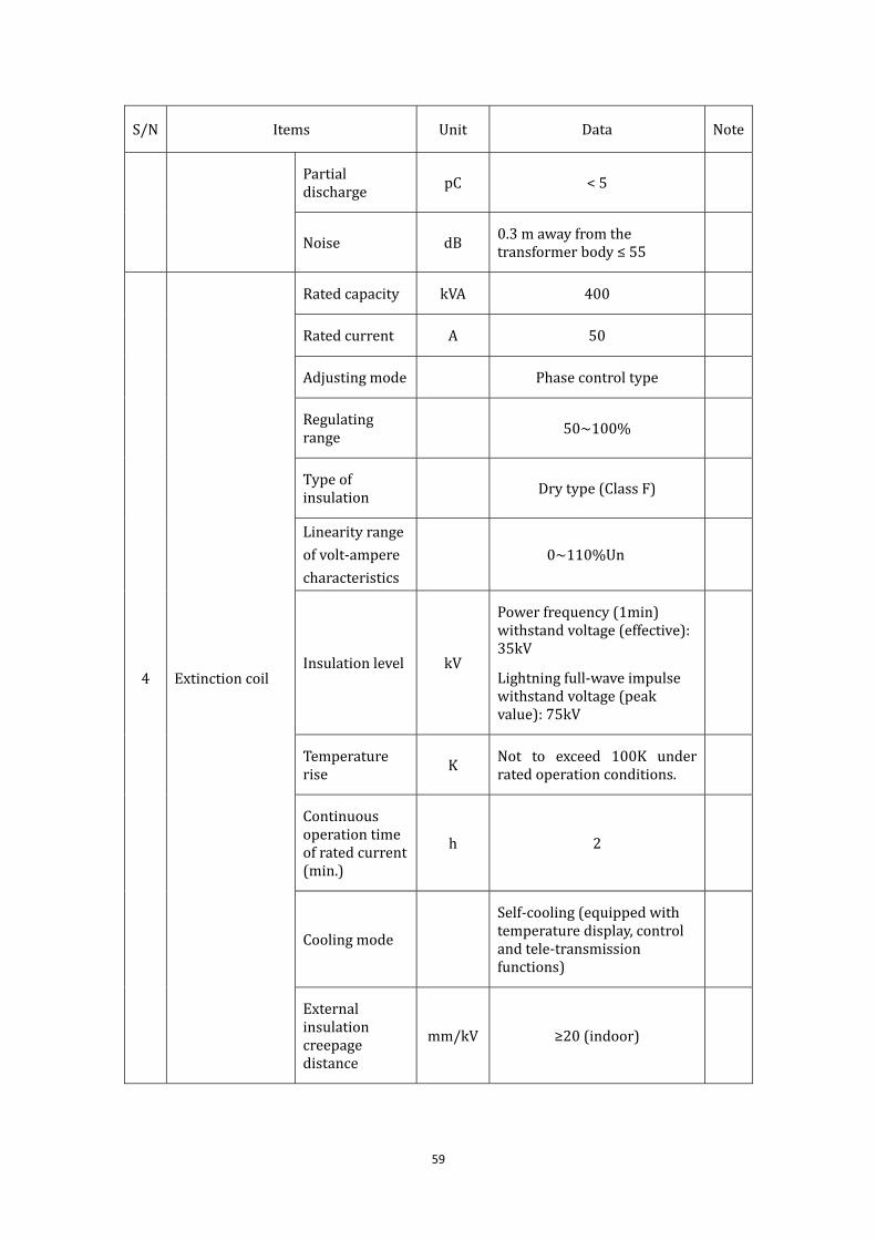
S/N Items Unit Data Note
Partialdischarge
pC <5
Noise dB0.3mawayfromthetransformerbody≤55
4 Extinctioncoil
Ratedcapacity kVA 400
Ratedcurrent A 50
Adjustingmode Phasecontroltype
Regulatingrange
50~100%
Typeofinsulation Drytype(ClassF)
Linearityrange
ofvolt‐ampere
characteristics
0~110%Un
Insulationlevel kV
Powerfrequency(1min)withstandvoltage(effective):35kV
Lightningfull‐waveimpulsewithstandvoltage(peakvalue):75kV
Temperaturerise
K Not to exceed 100K underratedoperationconditions.
Continuousoperationtimeofratedcurrent(min.)
h 2
Coolingmode
Self‐cooling(equippedwithtemperaturedisplay,controlandtele‐transmissionfunctions)
Externalinsulationcreepagedistance
mm/kV ≥20(indoor)

60
S/N Items Unit Data Note
Partialdischarge
pC <5
Noise dB0.3mawayfromthetransformerbody≤55
Electricallifeofswitchcontactontapswitch
Notlessthan200,000timesofmovement
Mechanicallifeswitchcontactontapswitch
Notlessthan800,000timesofmovement
5 Controlequipment
Type
Highreliability,highdegreeofintegration, dedicatedcomputer or programmingcontroller for industrial usewithmodularstructure.
Controlvoltage VDC220VorDC110V,reliableworkingvoltagerange75%~115%
Measuringerrorofcapacitancecurrent
% ‐2~+2
Measuringerrorforneutralpointdisplacementvoltage
% ‐2~+2
Recordingtimesoffaultinformation
Times 500
Powerfrequencywithstandvoltage
kV 2
Timesoffaultrecording
Times ≥50

61
S/N Items Unit Data Note
Tuning‐offdegree
% ≤10
Neutralpointdisplacementvoltageofthegridatmountingpoint
≯15%ofnominalphase
voltage
Mainfunctions
Functionsofman‐machineinteraction,self‐checking,alarming,printing,memory,display,tele‐transmission,on‐linerunning,automaticblocking(turn‐adjustingtype),hibernation,lineselectionprinciple,statisticsandfaultrecording;IEC‐61850protocolinterfaceisrequiredforIntelligentSubstation.
6
Dampingresistor
(Turns‐adjustingtype)
Resistancevalue
Ω
Long‐timeworkingcurrent
A 10
DCresistanceallowableerror % ±2
Short‐timeallowablecurrent
kA
Earthinsulation
MΩ >100
7 Lineselectiondevice(options)
Type
Ifturn‐adjustingtypeisapplied,lineselectiondeviceofparalleledmediumresistanceshallbeselected.
8 BoxoutercoverProtectiongrade
NotlessthanIP20
(Indoor)

62
Part9:
PowerTransformerHouse
TechnicalData

63
1. Standardcompliance
Standard Description
IEC60038 StandardVoltage
IEC60076 PowerTransformers
IEC62271‐102 AlternatingCurrentDisconnectorsandEarthingSwitches
GB4585.2 ArtificialPollution Test Methods of Composite Insulator
GB1208 CurrentTransformer
IEC60071‐1:2011 InsulationCo‐ordinationforHigh‐voltagePowerTransmissionand
TransformationEquipment
GB/T775.3‐1987 InsulatorTestMethod
GB5582‐1993 ExternalInsulationPollutionClassesofHighVoltageElectricPower
Equipments
IEC60270 High‐VoltageTestTechniques–PartialDischargeMeasurements
GB/T11604‐1989 TestMethodsforMeasuringRadioInterferenceforHighVoltage
Equipment
IEC60060 High‐voltageTestTechniques
IEC60099 SurgeArresters
GB50150‐2006 Standardfor Hand‐overTestofElectricEquipmentInstallation...
ISO780‐1985 Packaging‐PictorialMarkingsforHandlingofgoods
2. Powertransformertechnicaldata
Refertotransformerdatafromsupplier.

64
Part10:
SecondaryHouse
TechnicalData

65
Seededicateddocument<SecondaryHouseTechnicalData>

66
Related Documents