DS200-11 March ’06 ©2005 RF Solutions Ltd, www.rfsolutions.co.uk Page 1 Tel 01273 898000 Fax 01273 480661 Modular Radio Telemetry System 200 Series • Simple to Use Remote Control • 8 Channels per Transmitter • 16 Channels per Receiver • Upto 48 Transmitters per system • Auto Transmit Mode • Secure RF Protocol • Automatic ‘Watchdog’ Transmission • Range: ¾ Upto 200 metres at 433MHz ¾ Upto 1,000 metres at 433MHz Narrow Band. ¾ Upto 6,000 metres at 458MHz • Requires no radio license • Relay Outputs upto 30A @ 230Vac • All Modules supplied with Antenna Remote Telemetry Systems are well suited to industrial switching applications where telemetry signals need to be sent remotely from one location to another. This system allows multiple transmitters to a single receiver or a single transmitter to multiple receivers. Each Transmitter module accepts upto 8 pairs of ‘Volt Free’ contacts as inputs via screw terminals. Each Receiver has 16 outputs arranged as 4 x 4 easy plug in connectors to interface to any combination of output modules. Any of the output modules connect directly to the receiver (cable supplied) to provide transistor switching or relay outputs.

Welcome message from author
This document is posted to help you gain knowledge. Please leave a comment to let me know what you think about it! Share it to your friends and learn new things together.
Transcript
DS200-11 March ’06 ©2005 RF Solutions Ltd, www.rfsolutions.co.uk Page 1
Tel 01273 898000 Fax 01273 480661
Modular Radio Telemetry System 200 Series
• Simple to Use Remote Control • 8 Channels per Transmitter • 16 Channels per Receiver • Upto 48 Transmitters per system • Auto Transmit Mode • Secure RF Protocol • Automatic ‘Watchdog’ Transmission
• Range: Upto 200 metres at 433MHz Upto 1,000 metres at 433MHz Narrow Band. Upto 6,000 metres at 458MHz
• Requires no radio license • Relay Outputs upto 30A @ 230Vac • All Modules supplied with Antenna
Remote Telemetry Systems are well suited to industrial switching applications where telemetry signals need to be sent remotely from one location to another. This system allows multiple transmitters to a single receiver or a single transmitter to multiple receivers. Each Transmitter module accepts upto 8 pairs of ‘Volt Free’ contacts as inputs via screw terminals. Each Receiver has 16 outputs arranged as 4 x 4 easy plug in connectors to interface to any combination of output modules. Any of the output modules connect directly to the receiver (cable supplied) to provide transistor switching or relay outputs.
DS200-11 March ’06 ©2005 RF Solutions Ltd, www.rfsolutions.co.uk Page 2
Tel 01273 898000 Fax 01273 480661
Modular Radio Telemetry System 200 Series
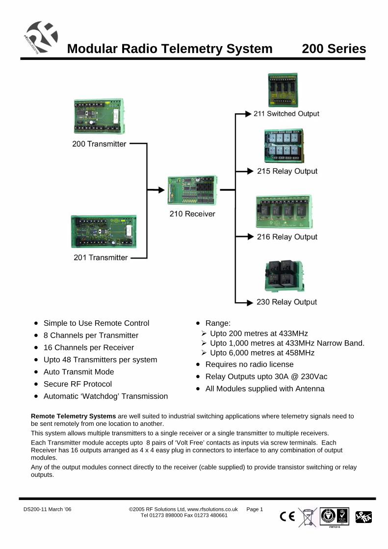
Transmitters • 8 Input Channels
• Volt Free contact Inputs via Screw Terminals
• 12 / 24Vdc Supply
• Low Power Battery Version
200 Transmitter: Standard transmitter 201 Transmitter: Low Power Transmitter . (Designed for battery powered applications)
Part Number Description Range** (Metres)
Freq (MHz)
Compatible Decoders
200-433FR FM Transmitter 200 433.92 210-433F
200-525NR FM Narrow Band Transmitter 1,000 434.525 210-525N
200-458FR FM High Power Transmitter 6,000 458.850 210-458F
201-525NR FM Narrow Band Transmitter 1,000 434.525 210- 525N
201-458FR FM High Power Transmitter 6,000 458.850 210-458F
Receivers • 16 Output Channels
• Volt Free contact Inputs via Screw Terminals
• 12 / 24Vdc Supply
• Low Power Battery Version
Part Number Description Range** (Metres)
Freq (MHz)
Compatible Transmitter
210-433FR FM Receiver 200 433.92 200/201-433F
210-525NR FM Narrow Band Receiver 1,000 434.525 200/201-525N
210-458FR FM High Power REceiver 6,000 458.850 200/201-458F
Output Modules • Connect Directly to 210 Rx (Cable Supplied)
• no power connections required
Part Number Description No of Outputs
Max Switching (per output)
211 Darlington Driver Outputs 16 0.5A @ 50V (Overall total 1A)
215 Relay Module 8 5A @230Vac
216 Relay Module 4 5A @230Vac
230 Relays Module 4 30A @230Vac
DS200-11 March ’06 ©2005 RF Solutions Ltd, www.rfsolutions.co.uk Page 3
Tel 01273 898000 Fax 01273 480661
Modular Radio Telemetry System 200 Series
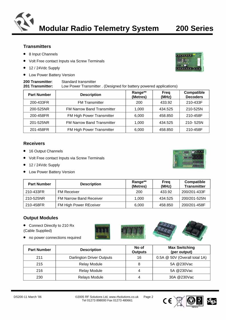
Enclosure / Power Supply • IP56 Insulation Class 2
• DIN Rails mounted on Steel Plate
• 12Vdc 1A PSU incorporated accepts 110-240Vac (5A Fused)
Dimensions External 315 x 235 x 130mm Internal 300 x 220 x 120mm DIN Rail length 1 285mm DIN Rail length 2 180mm
Part No Description
ENC-DA3 DIN Rail Enclosure Assembly, Two Mounting Rails, 12Vdc PSU Fitted
PSU12V1AIN-IP Power Supply 110-240Vac input, 12Vdc 1A Output
Custom systems We regularly supply pre-wired / bespoke systems, please contact our sales dept for further assistance
R. F. Solutions Ltd., Unit 21, Cliffe Industrial Estate, South Street, Lewes,
E Sussex, BN8 6JL. England
Tel +44 (0)1273 898 000 Fax +44 (0)1273 480 661 Email [email protected] http://www.rfsolutions.co.uk
RF Solutions is a member of the Low Power Radio Association
Information contained in this document is believed to be accurate, however no representation or warranty is given and R.F. Solutions Ltd. assumes no liability with respect to the accuracy of such information. Use of R.F.Solutions products as critical components in life support systems is not authorised except with express written approval from R.F.Solutions Ltd.
DS200-11 March ’06 ©2005 RF Solutions Ltd, www.rfsolutions.co.uk Page 4
Tel 01273 898000 Fax 01273 480661
Modular Radio Telemetry System 200 Series
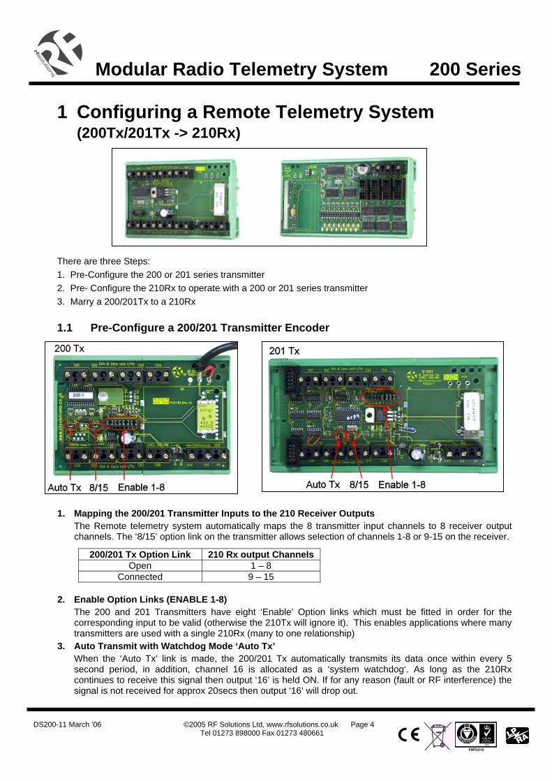
1 Configuring a Remote Telemetry System (200Tx/201Tx -> 210Rx)
There are three Steps: 1. Pre-Configure the 200 or 201 series transmitter 2. Pre- Configure the 210Rx to operate with a 200 or 201 series transmitter 3. Marry a 200/201Tx to a 210Rx
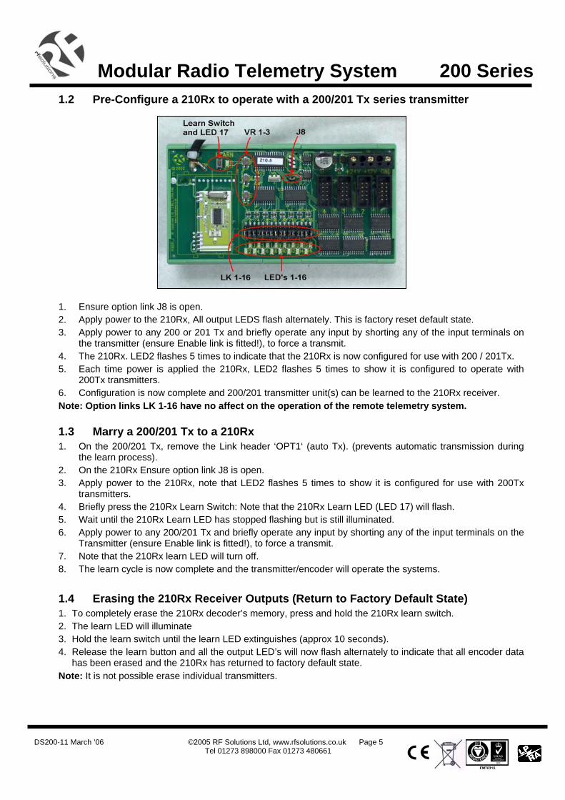
1.1 Pre-Configure a 200/201 Transmitter Encoder
1. Mapping the 200/201 Transmitter Inputs to the 210 Receiver Outputs
The Remote telemetry system automatically maps the 8 transmitter input channels to 8 receiver output channels. The ‘8/15’ option link on the transmitter allows selection of channels 1-8 or 9-15 on the receiver.
2. Enable Option Links (ENABLE 1-8) The 200 and 201 Transmitters have eight ‘Enable’ Option links which must be fitted in order for the corresponding input to be valid (otherwise the 210Tx will ignore it). This enables applications where many transmitters are used with a single 210Rx (many to one relationship)
3. Auto Transmit with Watchdog Mode ‘Auto Tx’ When the ‘Auto Tx’ link is made, the 200/201 Tx automatically transmits its data once within every 5 second period, in addition, channel 16 is allocated as a ‘system watchdog‘. As long as the 210Rx continues to receive this signal then output ‘16’ is held ON. If for any reason (fault or RF interference) the signal is not received for approx 20secs then output ‘16’ will drop out.
200/201 Tx Option Link 210 Rx output Channels Open 1 – 8
Connected 9 – 15
DS200-11 March ’06 ©2005 RF Solutions Ltd, www.rfsolutions.co.uk Page 5
Tel 01273 898000 Fax 01273 480661
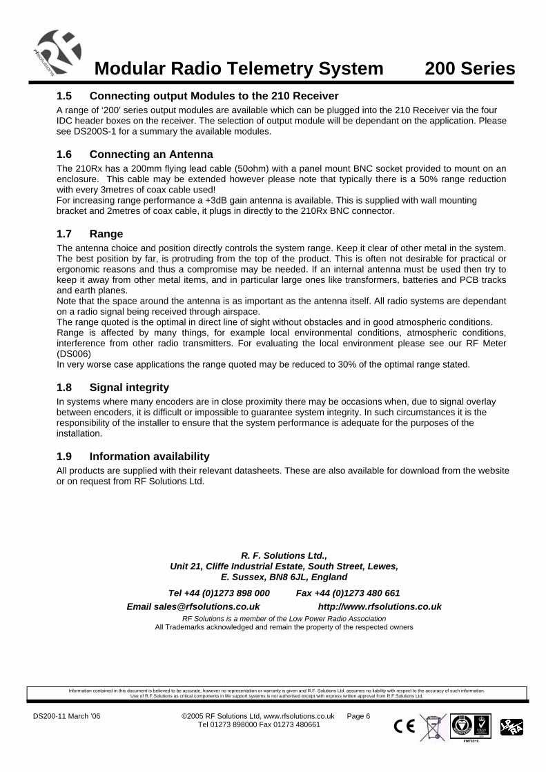
Modular Radio Telemetry System 200 Series 1.2 Pre-Configure a 210Rx to operate with a 200/201 Tx series transmitter
1. Ensure option link J8 is open. 2. Apply power to the 210Rx, All output LEDS flash alternately. This is factory reset default state. 3. Apply power to any 200 or 201 Tx and briefly operate any input by shorting any of the input terminals on
the transmitter (ensure Enable link is fitted!), to force a transmit. 4. The 210Rx. LED2 flashes 5 times to indicate that the 210Rx is now configured for use with 200 / 201Tx. 5. Each time power is applied the 210Rx, LED2 flashes 5 times to show it is configured to operate with
200Tx transmitters. 6. Configuration is now complete and 200/201 transmitter unit(s) can be learned to the 210Rx receiver. Note: Option links LK 1-16 have no affect on the operation of the remote telemetry system.
1.3 Marry a 200/201 Tx to a 210Rx 1. On the 200/201 Tx, remove the Link header ‘OPT1‘ (auto Tx). (prevents automatic transmission during
the learn process). 2. On the 210Rx Ensure option link J8 is open. 3. Apply power to the 210Rx, note that LED2 flashes 5 times to show it is configured for use with 200Tx
transmitters. 4. Briefly press the 210Rx Learn Switch: Note that the 210Rx Learn LED (LED 17) will flash. 5. Wait until the 210Rx Learn LED has stopped flashing but is still illuminated. 6. Apply power to any 200/201 Tx and briefly operate any input by shorting any of the input terminals on the
Transmitter (ensure Enable link is fitted!), to force a transmit. 7. Note that the 210Rx learn LED will turn off. 8. The learn cycle is now complete and the transmitter/encoder will operate the systems.
1.4 Erasing the 210Rx Receiver Outputs (Return to Factory Default State) 1. To completely erase the 210Rx decoder’s memory, press and hold the 210Rx learn switch. 2. The learn LED will illuminate 3. Hold the learn switch until the learn LED extinguishes (approx 10 seconds). 4. Release the learn button and all the output LED’s will now flash alternately to indicate that all encoder data
has been erased and the 210Rx has returned to factory default state. Note: It is not possible erase individual transmitters.
DS200-11 March ’06 ©2005 RF Solutions Ltd, www.rfsolutions.co.uk Page 6
Tel 01273 898000 Fax 01273 480661
Modular Radio Telemetry System 200 Series 1.5 Connecting output Modules to the 210 Receiver A range of ‘200’ series output modules are available which can be plugged into the 210 Receiver via the four IDC header boxes on the receiver. The selection of output module will be dependant on the application. Please see DS200S-1 for a summary the available modules.
1.6 Connecting an Antenna The 210Rx has a 200mm flying lead cable (50ohm) with a panel mount BNC socket provided to mount on an enclosure. This cable may be extended however please note that typically there is a 50% range reduction with every 3metres of coax cable used! For increasing range performance a +3dB gain antenna is available. This is supplied with wall mounting bracket and 2metres of coax cable, it plugs in directly to the 210Rx BNC connector.
1.7 Range The antenna choice and position directly controls the system range. Keep it clear of other metal in the system. The best position by far, is protruding from the top of the product. This is often not desirable for practical or ergonomic reasons and thus a compromise may be needed. If an internal antenna must be used then try to keep it away from other metal items, and in particular large ones like transformers, batteries and PCB tracks and earth planes. Note that the space around the antenna is as important as the antenna itself. All radio systems are dependant on a radio signal being received through airspace. The range quoted is the optimal in direct line of sight without obstacles and in good atmospheric conditions. Range is affected by many things, for example local environmental conditions, atmospheric conditions, interference from other radio transmitters. For evaluating the local environment please see our RF Meter (DS006) In very worse case applications the range quoted may be reduced to 30% of the optimal range stated.
1.8 Signal integrity In systems where many encoders are in close proximity there may be occasions when, due to signal overlay between encoders, it is difficult or impossible to guarantee system integrity. In such circumstances it is the responsibility of the installer to ensure that the system performance is adequate for the purposes of the installation.
1.9 Information availability All products are supplied with their relevant datasheets. These are also available for download from the website or on request from RF Solutions Ltd.
R. F. Solutions Ltd., Unit 21, Cliffe Industrial Estate, South Street, Lewes,
E. Sussex, BN8 6JL, England
Tel +44 (0)1273 898 000 Fax +44 (0)1273 480 661 Email [email protected] http://www.rfsolutions.co.uk
RF Solutions is a member of the Low Power Radio Association All Trademarks acknowledged and remain the property of the respected owners
Information contained in this document is believed to be accurate, however no representation or warranty is given and R.F. Solutions Ltd. assumes no liability with respect to the accuracy of such information. Use of R.F.Solutions as critical components in life support systems is not authorised except with express written approval from R.F.Solutions Ltd.
DS200-11 March ’06 ©2005 RF Solutions Ltd, www.rfsolutions.co.uk Page 7
Tel 01273 898000 Fax 01273 480661
Modular Radio Telemetry System 200 Series
Module Technical Specifications
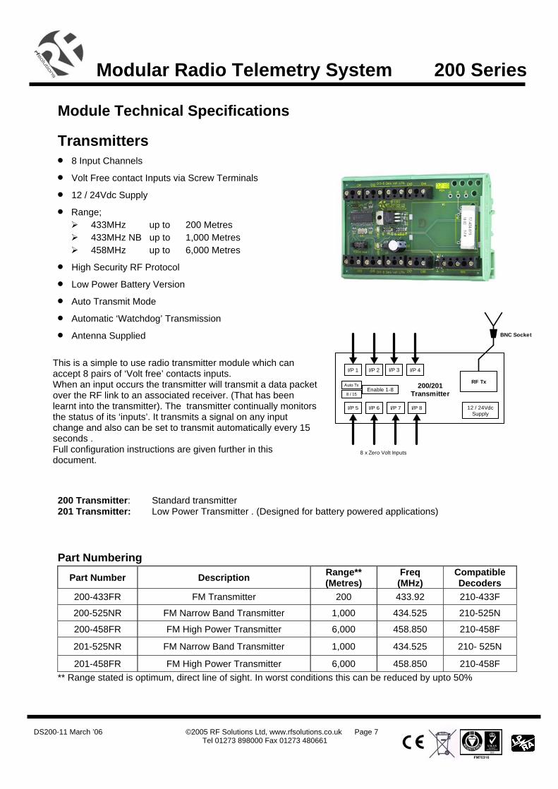
Transmitters • 8 Input Channels
• Volt Free contact Inputs via Screw Terminals
• 12 / 24Vdc Supply
• Range; 433MHz up to 200 Metres 433MHz NB up to 1,000 Metres 458MHz up to 6,000 Metres
• High Security RF Protocol
• Low Power Battery Version
• Auto Transmit Mode
• Automatic ‘Watchdog’ Transmission
• Antenna Supplied
200 Transmitter: Standard transmitter 201 Transmitter: Low Power Transmitter . (Designed for battery powered applications)
Part Numbering Part Number Description Range**
(Metres) Freq
(MHz) Compatible Decoders
200-433FR FM Transmitter 200 433.92 210-433F
200-525NR FM Narrow Band Transmitter 1,000 434.525 210-525N
200-458FR FM High Power Transmitter 6,000 458.850 210-458F
201-525NR FM Narrow Band Transmitter 1,000 434.525 210- 525N
201-458FR FM High Power Transmitter 6,000 458.850 210-458F ** Range stated is optimum, direct line of sight. In worst conditions this can be reduced by upto 50%
I/P 5
8 x Zero Volt Inputs
RF Tx200/201Transmitter
12 / 24VdcSupply
I/P 6 I/P 7 I/P 8
I/P 1 I/P 2 I/P 3 I/P 4
BNC Socket
Enable 1-8Auto Tx
8 / 15
This is a simple to use radio transmitter module which can accept 8 pairs of ‘Volt free’ contacts inputs. When an input occurs the transmitter will transmit a data packet over the RF link to an associated receiver. (That has been learnt into the transmitter). The transmitter continually monitors the status of its ‘inputs’. It transmits a signal on any input change and also can be set to transmit automatically every 15 seconds . Full configuration instructions are given further in this document.
DS200-11 March ’06 ©2005 RF Solutions Ltd, www.rfsolutions.co.uk Page 8
Tel 01273 898000 Fax 01273 480661
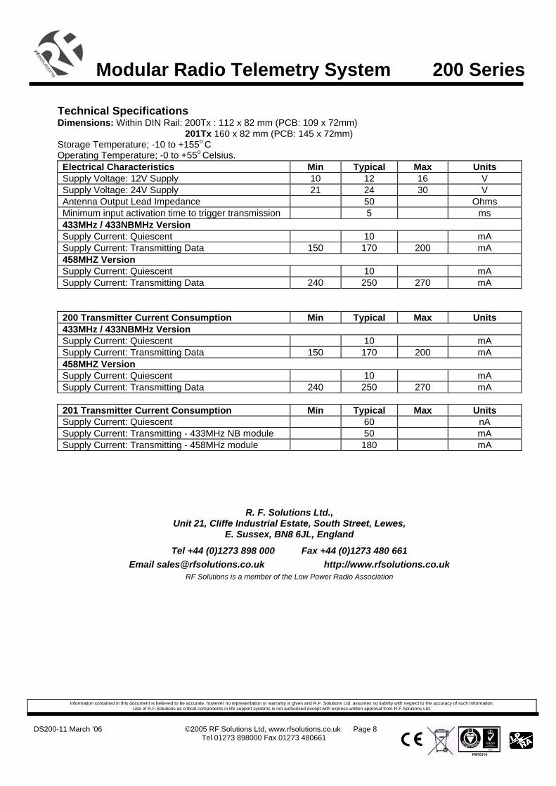
Modular Radio Telemetry System 200 Series Technical Specifications Dimensions: Within DIN Rail: 200Tx : 112 x 82 mm (PCB: 109 x 72mm) 201Tx 160 x 82 mm (PCB: 145 x 72mm) Storage Temperature; -10 to +155o C Operating Temperature; -0 to +55o Celsius. Electrical Characteristics Min Typical Max Units Supply Voltage: 12V Supply 10 12 16 V Supply Voltage: 24V Supply 21 24 30 V Antenna Output Lead Impedance 50 Ohms Minimum input activation time to trigger transmission 5 ms 433MHz / 433NBMHz Version Supply Current: Quiescent 10 mA Supply Current: Transmitting Data 150 170 200 mA 458MHZ Version Supply Current: Quiescent 10 mA Supply Current: Transmitting Data 240 250 270 mA
200 Transmitter Current Consumption Min Typical Max Units 433MHz / 433NBMHz Version Supply Current: Quiescent 10 mA Supply Current: Transmitting Data 150 170 200 mA 458MHZ Version Supply Current: Quiescent 10 mA Supply Current: Transmitting Data 240 250 270 mA
201 Transmitter Current Consumption Min Typical Max Units Supply Current: Quiescent 60 nA Supply Current: Transmitting - 433MHz NB module 50 mA Supply Current: Transmitting - 458MHz module 180 mA
R. F. Solutions Ltd., Unit 21, Cliffe Industrial Estate, South Street, Lewes,
E. Sussex, BN8 6JL, England
Tel +44 (0)1273 898 000 Fax +44 (0)1273 480 661 Email [email protected] http://www.rfsolutions.co.uk
RF Solutions is a member of the Low Power Radio Association
Information contained in this document is believed to be accurate, however no representation or warranty is given and R.F. Solutions Ltd. assumes no liability with respect to the accuracy of such information. Use of R.F.Solutions as critical components in life support systems is not authorised except with express written approval from R.F.Solutions Ltd.
DS200-11 March ’06 ©2005 RF Solutions Ltd, www.rfsolutions.co.uk Page 9
Tel 01273 898000 Fax 01273 480661
Modular Radio Telemetry System 200 Series Receivers
Technical Specifications Dimensions: Within DIN Rail: 138 x 82 mm (PCB: 133 x 72mm) Storage Temperature: -10 to +70o Celsius. Operating Temperature: 0 to +55o Celsius. Electrical Characteristics Min Typical Max Units Supply Voltage: 12V Supply 10 12 16 V Supply Voltage: 24V Supply 21 24 30 V Supply Current : Quiescent 25 mA Time from Tx Switch depressed to 210Rx output 100 mSecs Time from Tx Switch release to Decoder output 200 mSecs Switched output Voltage (I out = 1mA) Logic Low Logic High
0
3.5
0.2 3.8
0.8 5
V V
Part Numbering Part No Description
210-433FR Receiver Decoder 16 Channels DIN Rail Mounting, FM @ 433.92MHz
210-525NR Receiver Decoder 16 Channels DIN Rail Mounting, FM Narrow Band @ 434.525MHz
210-458FR Receiver Decoder 16 Channels DIN Rail Mounting, FM High Power @ 458.850MHz
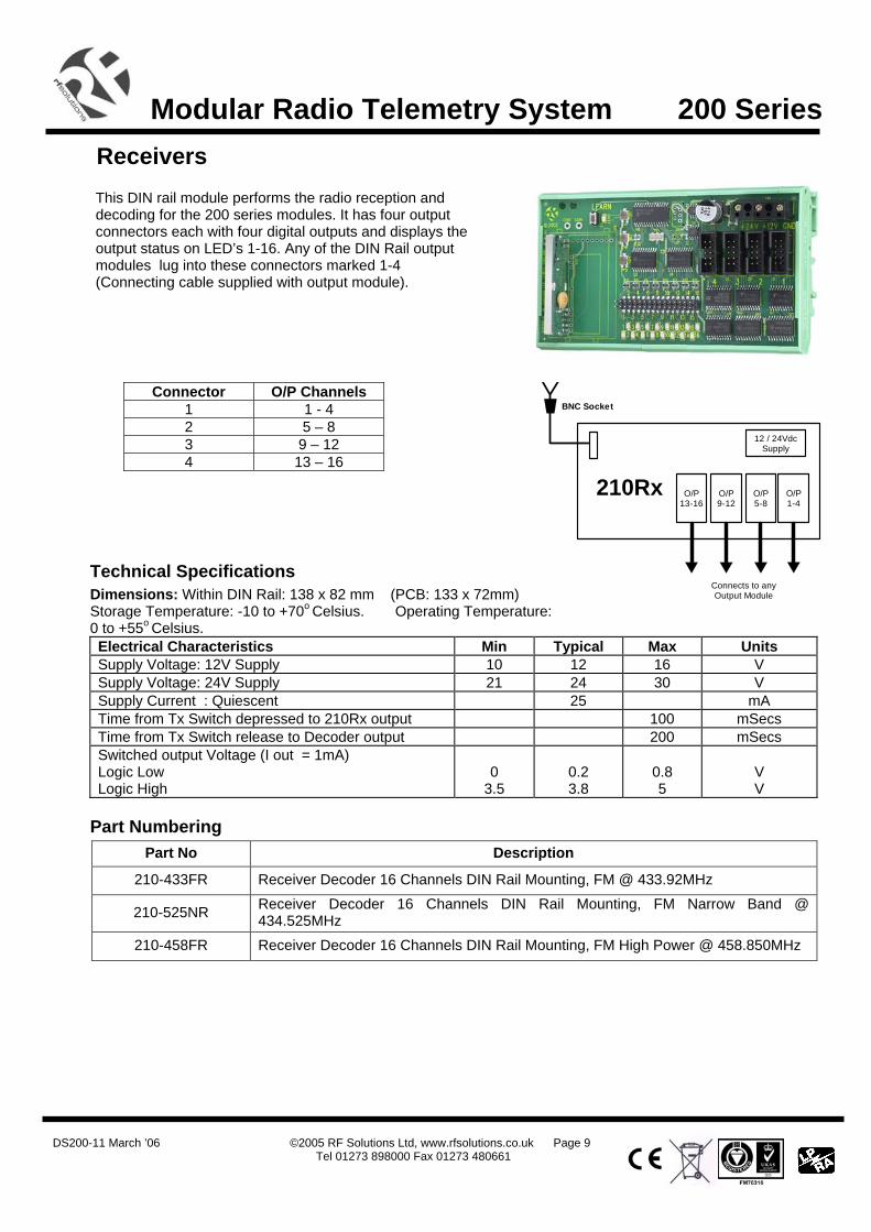
Connector O/P Channels 1 1 - 4 2 5 – 8 3 9 – 12 4 13 – 16
O/P13-16
Connects to anyOutput Module
210Rx O/P9-12
O/P5-8
O/P1-4
12 / 24VdcSupply
BNC Socket
This DIN rail module performs the radio reception and decoding for the 200 series modules. It has four output connectors each with four digital outputs and displays the output status on LED’s 1-16. Any of the DIN Rail output modules lug into these connectors marked 1-4 (Connecting cable supplied with output module).
DS200-11 March ’06 ©2005 RF Solutions Ltd, www.rfsolutions.co.uk Page 10
Tel 01273 898000 Fax 01273 480661
Modular Radio Telemetry System 200 Series Output Modules 211 Darlington Output
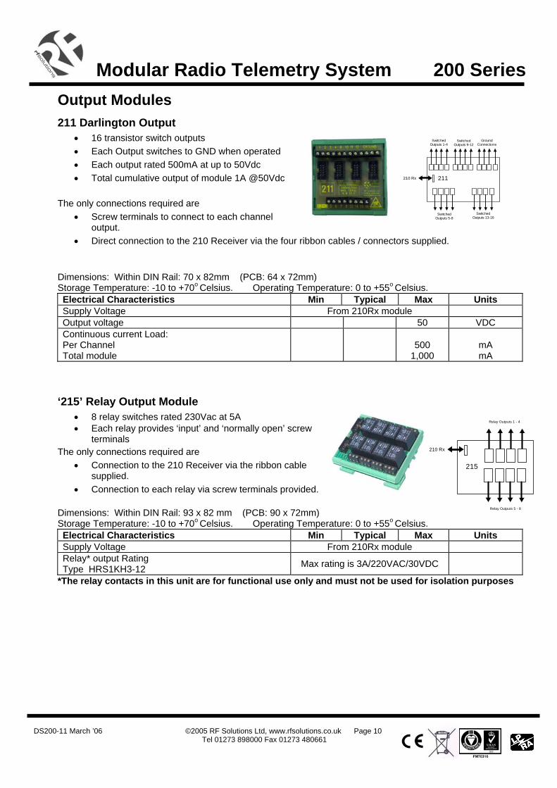
• 16 transistor switch outputs • Each Output switches to GND when operated • Each output rated 500mA at up to 50Vdc • Total cumulative output of module 1A @50Vdc
The only connections required are
• Screw terminals to connect to each channel output.
• Direct connection to the 210 Receiver via the four ribbon cables / connectors supplied. Dimensions: Within DIN Rail: 70 x 82mm (PCB: 64 x 72mm) Storage Temperature: -10 to +70o Celsius. Operating Temperature: 0 to +55o Celsius. Electrical Characteristics Min Typical Max Units Supply Voltage From 210Rx module Output voltage 50 VDC Continuous current Load: Per Channel Total module
500 1,000
mA mA
‘215’ Relay Output Module • 8 relay switches rated 230Vac at 5A • Each relay provides ‘input’ and ‘normally open’ screw
terminals The only connections required are
• Connection to the 210 Receiver via the ribbon cable supplied.
• Connection to each relay via screw terminals provided. Dimensions: Within DIN Rail: 93 x 82 mm (PCB: 90 x 72mm) Storage Temperature: -10 to +70o Celsius. Operating Temperature: 0 to +55o Celsius. Electrical Characteristics Min Typical Max Units Supply Voltage From 210Rx module Relay* output Rating Type HRS1KH3-12 Max rating is 3A/220VAC/30VDC
*The relay contacts in this unit are for functional use only and must not be used for isolation purposes
210 Rx 211
SwitchedOutputs 13-16
SwitchedOutputs 9-12
SwitchedOutputs 1-4
GroundConnections
SwitchedOutputs 5-8
210 Rx
Relay Outputs 5 - 8
Relay Outputs 1 - 4
215
DS200-11 March ’06 ©2005 RF Solutions Ltd, www.rfsolutions.co.uk Page 11
Tel 01273 898000 Fax 01273 480661
Modular Radio Telemetry System 200 Series
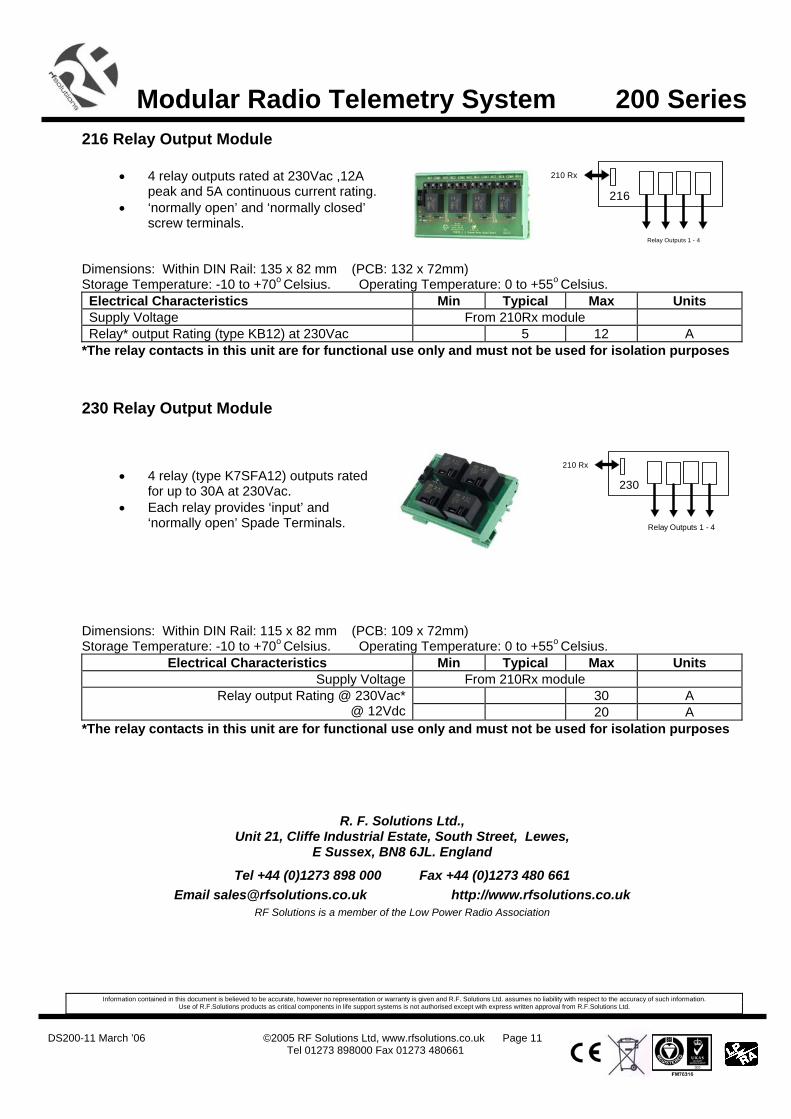
210 Rx
Relay Outputs 1 - 4
230
216 Relay Output Module
• 4 relay outputs rated at 230Vac ,12A peak and 5A continuous current rating.
• ‘normally open’ and ‘normally closed’ screw terminals.
Dimensions: Within DIN Rail: 135 x 82 mm (PCB: 132 x 72mm) Storage Temperature: -10 to +70o Celsius. Operating Temperature: 0 to +55o Celsius. Electrical Characteristics Min Typical Max Units Supply Voltage From 210Rx module Relay* output Rating (type KB12) at 230Vac 5 12 A
*The relay contacts in this unit are for functional use only and must not be used for isolation purposes
230 Relay Output Module
• 4 relay (type K7SFA12) outputs rated
for up to 30A at 230Vac. • Each relay provides ‘input’ and
‘normally open’ Spade Terminals.
Dimensions: Within DIN Rail: 115 x 82 mm (PCB: 109 x 72mm) Storage Temperature: -10 to +70o Celsius. Operating Temperature: 0 to +55o Celsius.
Electrical Characteristics Min Typical Max Units Supply Voltage From 210Rx module
30 A Relay output Rating @ 230Vac*@ 12Vdc 20 A
*The relay contacts in this unit are for functional use only and must not be used for isolation purposes
R. F. Solutions Ltd., Unit 21, Cliffe Industrial Estate, South Street, Lewes,
E Sussex, BN8 6JL. England
Tel +44 (0)1273 898 000 Fax +44 (0)1273 480 661 Email [email protected] http://www.rfsolutions.co.uk
RF Solutions is a member of the Low Power Radio Association
Information contained in this document is believed to be accurate, however no representation or warranty is given and R.F. Solutions Ltd. assumes no liability with respect to the accuracy of such information. Use of R.F.Solutions products as critical components in life support systems is not authorised except with express written approval from R.F.Solutions Ltd.
210 Rx
Relay Outputs 1 - 4
216
Related Documents