243 MODULAR PROTECTIONS AND DEVICES FOR ELECTRICAL PANELS MINIATURE CIRCUIT BREAKERS (MCB) DESCRIPTION In accordance with european and international standards: – EN 60898-1 | IEC 60898-1: “Circuit Breakers for Overcurrent Protection for household and similar installations”. Installation in DIN rail track, in electrical panels. OPERATION Magnetic operation. Thermal operation. CHARACTERISTICS Number of poles: 1;1P+N; 2; 3; 4. Voltage: 230/400V. Rated current: 1; 2; 3; 4; 6; 10; 16; 20; 25; 32; 40; 50; 63. Tripping curves: B; C; D. Breaking capacity (Icn): 4,5kA; 6kA; 10kA. Frequency: 50/60Hz. Energy limitation class: 3. Maximum voltage pulse: 6,2KV. Mechanical useful life: >20000 cycles. Electrical useful life: >8000 cycles. Connection by “U” Type Busbar. Connection by Pin Type Busbar. Terminals capacity: 25mm 2 . Terminals hight: 19mm. Maximum tightening torque: 2,0Nm. Mounting on symmetrical 35mm DIN rail track. Ambient temperature: -5ºC to 40ºC. TRIPPING CURVES MINUTES SECONDS MINUTES SECONDS MINUTES SECONDS TECHNICAL DATA SHEET MODUS 55 i

Welcome message from author
This document is posted to help you gain knowledge. Please leave a comment to let me know what you think about it! Share it to your friends and learn new things together.
Transcript

243
MODULAR PROTECTIONS AND DEVICES FOR ELECTRICAL PANELS
MINIATURE CIRCUIT BREAKERS (MCB)
DESCRIPTION
In accordance with european and international standards:
– EN 60898-1 | IEC 60898-1: “Circuit Breakers for Overcurrent Protection for
household and similar installations”.
Installation in DIN rail track, in electrical panels.
OPERATION Magnetic operation. Thermal operation.
CHARACTERISTICS Number of poles: 1;1P+N; 2; 3; 4. Voltage: 230/400V. Rated current: 1; 2; 3; 4; 6; 10; 16; 20; 25; 32; 40; 50; 63. Tripping curves: B; C; D. Breaking capacity (Icn): 4,5kA; 6kA; 10kA. Frequency: 50/60Hz. Energy limitation class: 3. Maximum voltage pulse: 6,2KV. Mechanical useful life: >20000 cycles. Electrical useful life: >8000 cycles. Connection by “U” Type Busbar. Connection by Pin Type Busbar. Terminals capacity: 25mm2. Terminals hight: 19mm. Maximum tightening torque: 2,0Nm. Mounting on symmetrical 35mm DIN rail track. Ambient temperature: -5ºC to 40ºC.
TRIPPING CURVES
MIN
UTE
SSE
CO
ND
S
MIN
UTE
SSE
CO
ND
S
MIN
UTE
SSE
CO
ND
S
TECHNICAL DATA SHEET MODUS 55
i

244
TECHNICAL DATA SHEET
MODULAR PROTECTIONS AND DEVICES FOR ELECTRICAL PANELS
MINIATURE CIRCUIT BREAKERS (MCB)
OPERATING TIME WHEN OPERATING IN OVERLOAD:
CURRENT OPERATING TIME ZONE
1,13 In T 1 hour
1,45 In T < 1 hour
2,55 InIn 32A t < 60 sec.
In > 32A t < 120 sec.
OPERATING TIME WHEN OPERATING IN SHORT-CIRCUIT:
TRIPPINGCHARACTERISTICS CURRENT OPERATING TIME ZONE USE
B3 In t 0,1 sec.
PROTECTION OF ELECTRICAL CIRCUITS WITH RESISTIVE LOADS.
5 In t < 0,1 sec.
C5 In t 0,1 sec.
PROTECTION OF GENERAL PURPOSE ELECTRICAL CIRCUITS.10 In t < 0,1 sec.
D10 In t 0,1 sec.
PROTECTION OF ELECTRICAL CIRCUITS WITH LOADS THAT PRODUCE HIGH TRANSIENT CURRENTS.
20 In t < 0,1 sec.
DIMENSIONS (mm)
MODUS 55

245
MODULAR PROTECTIONS AND DEVICES FOR ELECTRICAL PANELS
RESIDUAL CURRENT CIRCUIT BREAKER (RCCB)
DESCRIPTION
In accordance with european and international standards:
– EN 61008-1 | IEC 61008-1 (AC) and EN 61008-2-1 | IEC 61008-2-1 (A):
“Residual Current operated Circuit Breaker without integral Overcurrent Protection
for household and similar uses”.
Installation in DIN rail track, in electrical panels.
OPERATION Differential operation.
CHARACTERISTICS
Number of poles: 1P+N; 3P+N. Voltage: 240/415V. Rated current (A): 16; 25; 40; 63. Class: A; AC. Sensitivity (I n): 0,01A; 0,03A; 0,3A; 0,5A. Breaking capacity (Icn): 10kA. Frequency: 50/60Hz. Non-operating current: 0,5I n. Operating current: 0,5I n a I n. Tripping time: <0,1 Sec.. Electrical-mechanical useful life: >4000 cycles. Connection by “U” Type Busbar. Connection by Pin Type Busbar. Terminals capacity: 25mm2. Terminals hight: 19mm. Maximum tightening torque: 2,0Nm. Mounting on symmetrical 35mm DIN rail track.
DIMENSIONS (mm)
TECHNICAL DATA SHEET MODUS 55
i

246
TECHNICAL DATA SHEET
MODULAR PROTECTIONS AND DEVICES FOR ELECTRICAL PANELS
RESIDUAL CURRENT CIRCUIT BREAKER WITH OVERCURRENT PROTECTION (RCBO)
DESCRIPTION
In accordance with european and international standards that rule these type of products:
– EN 61009-1 | IEC 61009-1: “Residual Current operated Circuit-breakers with
integral overcurrent protection for household and similar uses”.
Installation in DIN rail track, in electrical panels.
OPERATION
Thermo-magneto operation. Differential operation.
CHARACTERISTICS
Number of poles: 1P+N. Voltage: 240V. Rated current (A): 6; 10; 16; 20; 25; 32; 40. Class: AC. Curve: C. Sensitivity (I n): 0,03A. Breaking capacity (Icn): 6kA. Frequency: 50/60Hz. Tripping time: <0,1 Sec.. Electrical-mechanical useful life: >4000 cycles. Connection by “U” Type Busbar. Connection by Pin Type Busbar. Terminals capacity: 16mm2 (rigide wire) 10mm2 (flexible wire). Maximum tightening torque: 2,0Nm. Mounting on symmetrical 35mm DIN rail track.
DIMENSIONS (mm)
MODUS 55

247
MODULAR PROTECTIONS AND DEVICES FOR ELECTRICAL PANELS
OVER-VOLTAGE AND SURGE PROTECTION DEVICES (SPD)(REF. 55410 1DC | 55420 1DC | 55440 1DC | 55460 1DC)
DESCRIPTION
In accordance with european and international standards:
– IEC 61643-1: “Low-voltage Surge Protective Devices - Part 1: Surge Protective Devices connected to Low-voltage Power Distribution Systems”.
Installation in DIN rail track, in electrical panels.
OPERATION The correct operation and performance of the SPDs are assured when the ground
installation is made in accordance with the official electrical codes, rules and prescriptions determined by the government or by the official entities.
The total length of the connection cables to the SPDs (L) must be as short as possible (<0,5m). It must be avoided to make derivations in the circuit of the SPDs. With currents up to
50A, the derivations must be made over the same terminals of the SPDs. The circuit where the SPDs are connected must be protected against overloads and short
circuits. It is recommended the use of a MCBs of 32 A - C Curve (C32). If the installation has different protection levels against over voltages, it is recommended
that the length of the cable that connects the main SPDs with a secondary SPDs is 1m, in order to avoid simultaneous conduction of both devices.
CHARACTERISTICS Number of poles: 1. Type: I. Rated Voltage (COV): 230V~ / 380V~. Maximum continuous operating voltage: 320V~ / 420V~. Protection level (8/20 sec): 1,0kVp (Red); 1,2kVp; 1,5kVp; 2,0kVp. Rated discharge current (8/20 sec): 5kA (Red); 10kA; 20kA; 30kA. Maximum discharge current (8/20 sec): 10kA (Red); 20kA (Yellow); 40kA (Grey); 60kA (Brown). Response time: <25ns. Operating temperature: -40ºC to +80ºC. Terminals capacity: 1x25mm2. Protection Index: IP20.
DIMENSIONS (mm)
TECHNICAL DATA SHEET MODUS 55
i

248
TECHNICAL DATA SHEET
MODULAR PROTECTIONS AND DEVICES FOR ELECTRICAL PANELS
3-PHASE VOLTAGE INDICATOR(REF. 55009)
DESCRIPTION
Indicates presence of three-phases voltage.
Installation in DIN rail track, in electrical panels.
CIRCUIT DIAGRAM
CHARACTERISTICS DIMENSIONS (mm) Voltage: 230/400V~
Consumption: 6mA
Frequency: 50/60Hz
Cables section: 0,2 - 2,5mm2
Protection Index: IP20.
Insulation Class: II.
WIRING DIAGRAML1L2L3N
3,5mm DIN TH 35
MODUS 55

249
MODULAR PROTECTIONS AND DEVICES FOR ELECTRICAL PANELS
1-PHASE VOLTAGE VALUE INDICATOR(REF. 55010)
DESCRIPTION
Indicates phase voltage value.
Installation in DIN rail track, in electrical panels.
CIRCUIT DIAGRAM VOLTAGE LEVELS
CHARACTERISTICS DIMENSIONS (mm)
Voltage: 230V~
Consumption: 24mA
Frequency: 50/60Hz
Cables section: 0,2 - 2,5mm2
Protection Index: IP20.
Insulation Class: II.
WIRING DIAGRAML1N
3,5mm DIN TH 35
TECHNICAL DATA SHEET MODUS 55
i

250
TECHNICAL DATA SHEET
MODULAR PROTECTIONS AND DEVICES FOR ELECTRICAL PANELS
3-PHASE VOLTAGE VALUE INDICATOR(REF. 55011)
DESCRIPTION
Indicates three-phase voltage value.
Installation in DIN rail track, in electrical panels.
CIRCUIT DIAGRAM VOLTAGE LEVELS
CHARACTERISTICS DIMENSIONS (mm) Voltage: 230/400V~
Consumption: 68mA
Frequency: 50/60Hz
Cables section: 0,2 - 2,5mm2
Protection Index: IP20.
Insulation Class: II.
WIRING DIAGRAML1L2L3N
3,5mm DIN TH 35
MODUS 55

251
TECHNICAL DATA SHEET MODUS 55
MODULAR PROTECTIONS AND DEVICES FOR ELECTRICAL PANELS
ELECTRONIC STAIRCASE TIME-DELAY SWITCH 16A(REF. 55030)
DESCRIPTION
Allows to connect and disconnect a lighting installation after a programmed time-delay.
The activation is made by the use of Push-buttons, Rocker Push-buttons or Rocker Push-buttons with Orienting Light according to the 3 wires diagram.
Installation in DIN rail track, in electrical panels.
OPERATION CIRCUIT DIAGRAM
CHARACTERISTICS DIMENSIONS (mm) Voltage: 230V~.
Consumption: 48mA.
Frequency: 50/60Hz.
Time adjustment: 10 sec. - 10 min.
Output: 1NO - 16A/250V~ 4000VA.
Cables section: 0,2 - 2,5mm2
Protection Index: IP20.
Insulation Class: II.
WIRING DIAGRAMS
With 3 wires With 4 wires
Ref. 21151/21152 Ref. 21151
LN
3,5mm DIN TH 35
i
252
MODULAR PROTECTIONS AND DEVICES FOR ELECTRICAL PANELS
STAIRCASE TIME-DELAY SWITCH 16A WITH BLOCKAGE(REF. 55031)
DESCRIPTION
Allows to connect and disconnect a lighting installation after a programmed time-delay.
The activation is made by the use of Push-buttons, Rocker Push-buttons or Rocker Push-buttons without Orienting Light.
Installation in DIN rail track, in electrical panels.
OPERATION MAXIMUM RECOMMENDED LOAD CIRCUIT DIAGRAM
CHARACTERISTICS DIMENSIONS (mm) Voltage: 230V~. Consumption: 25mA. Frequency: 50/60Hz. Time adjustment: 3 - 30 min. Current control: 300 A. Output: 1NO - 16A/250V~ 4000VA. Cables section: 0,2 - 2,5mm2
Protection Index: IP20. Insulation Class: II. Maximum leakage current: 200 A.
WIRING DIAGRAMS
11 14
Ref. 21151
LN
L/N Ref. 21153
LN
L/N
NL
11 14
3,5mm DIN TH 35
In 200 A
TECHNICAL DATA SHEETMODUS 55
2000 W
500W/VA
1000 W/VA
750 W/VA

253
TECHNICAL DATA SHEET MODUS 55
MODULAR PROTECTIONS AND DEVICES FOR ELECTRICAL PANELS
STAIRCASE TIME-DELAY SWITCH 10A(REF. 55510 SPA)
DESCRIPTION
Allows to connect and disconnect a lighting installation after a programmed time-delay.
The activation is made by the use of Push-buttons, Rocker Push-buttons or Rocker Push-buttons with Orienting Light.
Installation in DIN rail track, in electrical panels.
OPERATION MAXIMUM RECOMMENDED LOAD
By pressing the button, the load stays on as long as the time programmed in the device.
CHARACTERISTICS DIMENSIONS (mm)
230V~ - 50/60Hz.
Breaking capacity: 10A.
Time adjust ment: 45 seconds to 7 minutes.
Dimension: 1 Module DIN.
Operating temperature: -10ºC to 60ºC.
Protection Index: IP20.
Maximum leakage current: 50mA.
WIRING DIAGRAMS
with 3 wire with 4 wire
L
N
L
N
3000 W
500W/VA
500 W/VA
2000 W/VA
3000 W
500 W/VA
In 50mA
i

254
TECHNICAL DATA SHEET
MODULAR PROTECTIONS AND DEVICES FOR ELECTRICAL PANELS
CONTACTOR(REF. 55502 CTR)
DESCRIPTION
Allows to control a specific load that needs a High Rated Current throught a command that has a low breaking capacity, creating a separation of the high power circuit from the command circuit.
Installation in DIN rail track, in electrical panels.
CHARACTERISTICS DIMENSIONS (mm) Rated voltage: 230V~
Breaking capacity: 20A
Category: AC-1, AC-7a.
Frequency: 50/60Hz.
Operating Voltage: 230V~.
Outputs: 2NO.
Operating temperature: -10ºC to +50ºC.
Protection Index: IP20.
Insulation Class: II.
WIRING DIAGRAMLN
MODUS 55

255
TECHNICAL DATA SHEET MODUS 55
MODULAR PROTECTIONS AND DEVICES FOR ELECTRICAL PANELS
ELECTRONIC LATCHING RELAY 16A(REF. 55017)
DESCRIPTION
Allows to connect and disconnect a lighting installation using Rocker Push-buttons.
Installation in DIN rail track, in electrical panels.
OPERATION MAXIMUM RECOMMENDED LOAD CIRCUIT DIAGRAM
CHARACTERISTICS DIMENSIONS (mm) Voltage: 230V~. Consumption: 24mA. Frequency: 50/60Hz. Control current: 930 A. Output: 1NO - 16A/250V~ 4000VA. Cables section: 0,2 - 2,5mm2
Protection Index: IP20. Insulation Class: II.
WIRING DIAGRAMSLN
L/NRef. 21151
11 14 11 14
LN
L/N
N
N
Ref. 21153
3,5mm DIN TH 35
2000 W
500 W/VA
1000 W/VA
750 W/VA
In 200 A
i

256
TECHNICAL DATA SHEETMODUS 55
MODULAR PROTECTIONS AND DEVICES FOR ELECTRICAL PANELS
ANALOGUE DAILY 1 CHANNEL TIME SWITCH(REF. 55501 ANL)
DESCRIPTION
Allows to control the operation of an electric installation or an equipment according to a daily program.
The minimum time of a program is 15 minutes.
Installation in DIN rail track, in electrical panels.
MAXIMUM RECOMMENDED LOAD CIRCUIT DIAGRAM
CHARACTERISTICS DIMENSIONS (mm) Voltage: 230V~. Frequency: 50/60Hz. Breaking capacity: 16(4)A. Battery Back-up Time: NiMH - V80 H. Precision: 1 sec./day. Programming time: 24 hours/15 minutes. Consumption: 0,5W. Operating temperature: -10ºC - +45ºC . Protection Index: IP20. Insulation Class: II.
WIRING DIAGRAMLN
3,5mm DIN TH 35
2500 W
1200 W/VA
2000 W/VA
2500 W
1000 W/VA
900 W/VA
1000 W/VA
257
TECHNICAL DATA SHEET MODUS 55
MODULAR PROTECTIONS AND DEVICES FOR ELECTRICAL PANELS
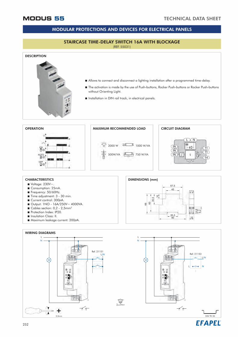
DIGITAL TIME SWITCHES(REF. 55037 | 55039)
DESCRIPTION
Allows to control an installation or equipment according to a daily and/or weekly programming.
Installation in DIN rail track, in electrical panels.
MAXIMUM RECOMMENDED LOAD CIRCUIT DIAGRAMS1 Circuit 2 Circuits
CHARACTERISTICS DIMENSIONS (mm) Voltage: 230V~. Frequency: 50/60Hz. 1 Circuit: 1NO + 1NC. 2 Circuits: 2NO + 2NC. Memory capacity: 400. Programming mode: daily/weekly. Operation mode: manual, automatic, random, pulse. Time change summer/winter: automatic, manual. Operation temperature: -20ºC - +60ºC. Cables section: 0,2 - 2,5mm2. Protection Index: IP20. Insulation Class: II.
WIRING DIAGRAMS1 Circuit 2 Circuits
LN
L/N
External Input
LN
L/N
External Input
Before installing the device, it is necessary to remove the security protection of the battery to avoid a discharge.! 3,5mm DIN TH 35
3000 W
500 W/VA
1000 W/VA
750 W/VA
i

258
TECHNICAL DATA SHEETMODUS 55
MODULAR PROTECTIONS AND DEVICES FOR ELECTRICAL PANELS
DAILY/WEEKLY 1 CHANNEL DIGITAL TIME SWITCH(REF. 55501 DIG)
DESCRIPTION
Allows to control the operation of an electric installation or equipment according to a daily or weekly program.
Can memorize the programs with a maximum capacity of 32 Programs.
Produces the automatic adjustment of the time in Summer and Winter. It’s possible to program a Stand By period.
Installation in DIN rail track, in electrical panels.
MAXIMUM RECOMMENDED LOAD CIRCUIT DIAGRAM
CHARACTERISTICS DIMENSIONS (mm)
Voltage: 230V~. Frequency: 50/60Hz. Breaking capacity: 16(10)A. Consumption: 1W. Memory capacity: 32. Output: ON, OFF and PULSE (1 to 59 sec.) Precision: 1 sec./day. Operating temperature: -10ºC - +50ºC Protection Index: IP20. Insulation Class: II.
WIRING DIAGRAMLN
3,5mm DIN TH 35
3000 W
1200 W/VA
2000 W/VA
3000 W
600 W/VA
400 W/VA
600 W/VA

259
TECHNICAL DATA SHEET MODUS 55
MODULAR PROTECTIONS AND DEVICES FOR ELECTRICAL PANELS
MODULAR ELECTRONIC DIMMER(REF. 55020)
DESCRIPTION
Allows to adjust the luminous flux of one or more lamps with Rocker Push-buttons.
Installation in DIN rail track, in electrical panels.
OPERATION MAXIMUM RECOMMENDED LOAD CIRCUIT DIAGRAM
CHARACTERISTICS DIMENSIONS (mm) Voltage: 230V~. Consumption: 10mA. Frequency: 50Hz. Power output (load): 30 - 500W. Cables section: 0,2 - 2,5mm2. Protection Index: IP20. Insulation Class: II.
WIRING DIAGRAMLN
L/N
3,5mm DIN TH 35
3000 W 300 W/VA 500 W/VA 500 W/VA
In 200 A
i

260
TECHNICAL DATA SHEET
MODULAR PROTECTIONS AND DEVICES FOR ELECTRICAL PANELS
VOLTAGE CONTROL RELAY SINGLE PHASE(REF. 55024)
DESCRIPTION
Allows to control the voltage over a circuit.
Installation in DIN rail track, in electrical panels.
OPERATION MAXIMUM RECOMMENDED LOAD CIRCUIT DIAGRAM
CHARACTERISTICS DIMENSIONS (mm)
Voltage: 230V~. Consumption: 35mA. Frequency: 50/60Hz. Minimum voltage: 170 - 225V~. Maximum voltage: 235 - 290V~. Output: 1NO/NC - 10A/250V~ 2500VA. Cables section: 0,2 - 2,5mm2. Protection Index: IP20. Insulation Class: II.
WIRING DIAGRAMSLN
M
TV
11 14
12
3,5mm DIN TH 35
MODUS 55
1250 W
300 W/VA
600 W/VA
450 W/VA

261
MODULAR PROTECTIONS AND DEVICES FOR ELECTRICAL PANELS
CURRENT CONTROL RELAY SINGLE PHASE 16A(REF. 55025)
DESCRIPTION
Allows to control the current in a circuit.
Installation in DIN rail track, in electrical panels.
OPERATION CIRCUIT DIAGRAM
CHARACTERISTICS DIMENSIONS (mm)
Voltage: 230V~. Current: 1,6 - 16A. Consumption: 34mA. Frequency: 50/60Hz. Output: 1NO/NC - 16A/250V~ 4000VA. Cables section: 0,2 - 2,5mm2. Protection Index: IP20. Insulation Class: II.
WIRING DIAGRAMSLN
PriorityCircuit
Non-priorityCircuit
LN
PriorityCircuit
Non-priorityCircuit
11 14
12
3,5mm DIN TH 35
TECHNICAL DATA SHEET MODUS 55
i
Related Documents