PIPE, WELD, VCR, VCO FITTINGS STANDARD TUBING MPC COMPONENTS HOSE / FLEXIBLE TUBING BELLOWS, DIAPHRAGM VALVES BALL & PLUG VALVES CHECK & RELIEF VALVES NEEDLE & METERING VALVES REGULATORS & FILTERS INSTRUMENT MANIFOLD SYSTEMS MEASUREMENT DEVICES REFERENCES MEDIUM- HIGH- PRESSURE TUBE FITTINGS Modular Platform Components (MPC) Surface-Mount Components, Substrates, Manifolds, Mounting Components, and Assembly Hardware MPC Series ■ ANSI/ISA 76.00.02-compliant design, 38.2 mm (1.5 in.) platform ■ Easy to configure, assemble, and maintain ■ Valves, filters, flowmeters, regulators, pressure gauges, and digital pressure-temperature transducers, as well as adapters for additional surface-mount components www.swagelok.com

Welcome message from author
This document is posted to help you gain knowledge. Please leave a comment to let me know what you think about it! Share it to your friends and learn new things together.
Transcript

Modular Platform Components (MPC) 1 PIPE, W
ELD, VCR, VCO FITTINGS
STANDARD TUBING
MPC
COMPONENTS
HOSE / FLEXIBLE TUBING
BELLOWS,
DIAPHRAGM
VALVES
BALL & PLUG VALVES
CHECK & RELIEF VALVES
NEEDLE & M
ETERING VALVES
REGULATORS & FILTERS
INSTRUMENT
MANIFOLD
SYSTEMS
MEASUREM
ENT DEVICES
REFERENCESM
EDIUM- HIGH-
PRESSURETUBE
FITTINGS
Modular Plat form Components (MPC)Sur face-Mount Components, Substrates, Mani fo lds, Mounting Components, and Assembly Hardware
MPC Ser ies■ ANSI/ISA 76.00.02-compliant design, 38.2 mm (1.5 in.) platform
■ Easy to configure, assemble, and maintain
■ Valves, filters, flowmeters, regulators, pressure gauges, and digital pressure-temperature transducers, as well as adapters for additional surface-mount components
www.swagelok.com
2 Modular SystemsTU
BE
FITTI
NGS
PIPE
, WEL
D,
VCR,
VCO
FIT
TING
S
STAN
DARD
TU
BING
MPC
COM
PONE
NTS
HOSE
/ FL
EXIB
LE
TUBI
NG
BELL
OWS,
DI
APHR
AGM
VA
LVES
BALL
& P
LUG
VALV
ES
NEED
LE &
M
ETER
ING
VA
LVES
CHEC
K &
RELIE
F VA
LVES
REGU
LATO
RS
& FIL
TERS
INST
RUM
ENT
MAN
IFOLD
SY
STEM
S
MEA
SURE
MEN
T DE
VICE
SRE
FERE
NCES
MED
IUM
- HIG
H-
PRES
SURE
Swagelok Surface-Mount Components
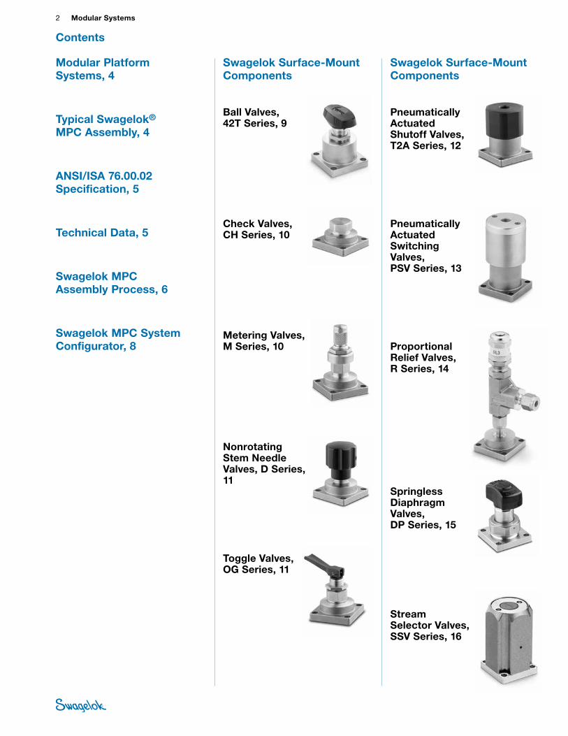
Ball Valves, 42T Series, 9
Check Valves, CH Series, 10
Metering Valves, M Series, 10
Nonrotating Stem Needle Valves, D Series, 11
Toggle Valves, OG Series, 11
Modular Platform Systems, 4
Typical Swagelok® MPC Assembly, 4
ANSI/ISA 76.00.02 Specification, 5
Technical Data, 5
Swagelok MPC Assembly Process, 6
Swagelok MPC System Configurator, 8
Contents
Swagelok Surface-Mount Components
Pneumatically Actuated Shutoff Valves, T2A Series, 12
Pneumatically Actuated Switching Valves, PSV Series, 13
Proportional Relief Valves, R Series, 14
Springless Diaphragm Valves, DP Series, 15
Stream Selector Valves, SSV Series, 16
Modular Platform Components (MPC) 3 PIPE, W
ELD, VCR, VCO FITTINGS
STANDARD TUBING
MPC
COMPONENTS
HOSE / FLEXIBLE TUBING
BELLOWS,
DIAPHRAGM
VALVES
BALL & PLUG VALVES
CHECK & RELIEF VALVES
NEEDLE & M
ETERING VALVES
REGULATORS & FILTERS
INSTRUMENT
MANIFOLD
SYSTEMS
MEASUREM
ENT DEVICES
REFERENCESM
EDIUM- HIGH-
PRESSURETUBE
FITTINGS
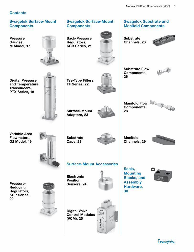
Swagelok Surface-Mount Components
Back-Pressure Regulators, KCB Series, 21
Tee-Type Filters, TF Series, 22
Surface-Mount Adapters, 23
Substrate Caps, 23
Surface-Mount Accessories
Electronic Position Sensors, 24
Digital Valve Control Modules (VCM), 25
Swagelok Substrate and Manifold Components
Substrate Channels, 26
Substrate Flow Components, 26
Manifold Flow Components, 28
Manifold Channels, 29
Seals, Mounting Blocks, and Assembly Hardware, 30
Swagelok Surface-Mount Components
Pressure Gauges, M Model, 17
Digital Pressure and Temperature Transducers, PTX Series, 18
Variable Area Flowmeters, G2 Model, 19
Pressure-Reducing Regulators, KCP Series, 20
Contents
4 Modular SystemsTU
BE
FITTI
NGS
PIPE
, WEL
D,
VCR,
VCO
FIT
TING
S
STAN
DARD
TU
BING
MPC
COM
PONE
NTS
HOSE
/ FL
EXIB
LE
TUBI
NG
BELL
OWS,
DI
APHR
AGM
VA
LVES
BALL
& P
LUG
VALV
ES
NEED
LE &
M
ETER
ING
VA
LVES
CHEC
K &
RELIE
F VA
LVES
REGU
LATO
RS
& FIL
TERS
INST
RUM
ENT
MAN
IFOLD
SY
STEM
S
MEA
SURE
MEN
T DE
VICE
SRE
FERE
NCES
MED
IUM
- HIG
H-
PRES
SURE
The components consist of a variety of Swagelok surface-mount components, which are ANSI/ISA 76.00.02-compliant, and a large selection of substrate and manifold flow components, which create the fluid distribution system.
Standard O-rings provide leak-tight seals between each surface-mount and substrate flow component and between the substrate and manifold flow components.
An MPC series assembly provides a compact fluid-distribution system with a reduced footprint for efficient use of component space. Modular technology allows the user to customize each system for a specific application and reduces installation and maintenance time. Surface-mount components can be serviced easily from the top of the assembly without disturbing any other components.
Surface-mount components, adapters, and caps are interchangeable on any surface-mount position because of the modularity of components and the use of the standard ANSI/ISA 76.00.02 interface.
Swagelok Modular Platform Components
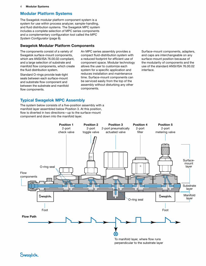
Typical Swagelok MPC Assembly The system below consists of a five-position assembly with a manifold layer assembled below Position 3. At this position, flow is diverted in two directions—up to the surface-mount component and down into the manifold layer.
To manifold layer, where flow runs perpendicular to the substrate layer
Flow Path
Position 1 2-port
check valve
Position 2 2-port
toggle valve
Position 5 2-port
metering valve
Position 3 2-port pneumatically
actuated valve
Foot
O-ring seal
Surface-mount layer
Position 4 2-port filter
Flow components
O-ring seal
Foot
The Swagelok modular platform component system is a system for use within process analyzer, sample-handling, and fluid distribution systems. The Swagelok MPC system includes a complete selection of MPC series components and a complementary configuration tool called the MPC System Configurator (page 8).
Modular Platform Systems
Substrate layer
Manifold layer
Modular Platform Components (MPC) 5 PIPE, W
ELD, VCR, VCO FITTINGS
STANDARD TUBING
MPC
COMPONENTS
HOSE / FLEXIBLE TUBING
BELLOWS,
DIAPHRAGM
VALVES
BALL & PLUG VALVES
CHECK & RELIEF VALVES
NEEDLE & M
ETERING VALVES
REGULATORS & FILTERS
INSTRUMENT
MANIFOLD
SYSTEMS
MEASUREM
ENT DEVICES
REFERENCESM
EDIUM- HIGH-
PRESSURETUBE
FITTINGSANSI/ISA 76.00.02 Specification
Modular Component Interfaces for Surface-Mount Fluid Distribution Components
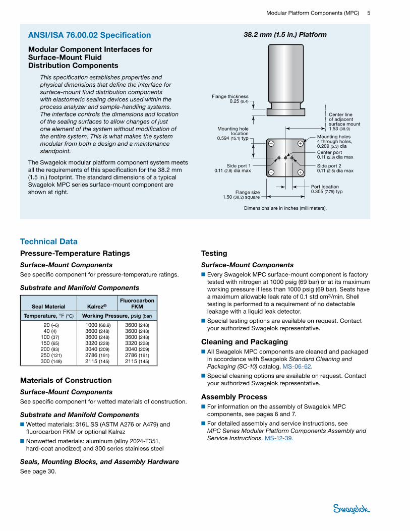
This specification establishes properties and physical dimensions that define the interface for surface-mount fluid distribution components with elastomeric sealing devices used within the process analyzer and sample-handling systems. The interface controls the dimensions and location of the sealing surfaces to allow changes of just one element of the system without modification of the entire system. This is what makes the system modular from both a design and a maintenance standpoint.
The Swagelok modular platform component system meets all the requirements of this specification for the 38.2 mm (1.5 in.) footprint. The standard dimensions of a typical Swagelok MPC series surface-mount component are shown at right.
Flange thickness 0.25 (6.4)
Mounting holes 4 through holes, 0.209 (5.3) diaCenter port 0.11 (2.8) dia max
Side port 2 0.11 (2.8) dia max
Side port 1 0.11 (2.8) dia max
Flange size 1.50 (38.2) square
Mounting hole location
0.594 (15.1) typ
Port location 0.305 (7.75) typ
Center line of adjacent surface mount 1.53 (38.9)
38.2 mm (1.5 in.) Platform
Dimensions are in inches (millimeters).
Pressure-Temperature Ratings
Surface-Mount Components See specific component for pressure-temperature ratings.
Substrate and Manifold Components
Seal Material Kalrez®Fluorocarbon
FKM
Temperature, °F (°C) Working Pressure, psig (bar)
20 (–6)40 (4)
100 (37)150 (65)200 (93)250 (121)300 (148)
1000 (68.9)3600 (248)3600 (248)3320 (228)3040 (209)2786 (191)2115 (145)
3600 (248)3600 (248)3600 (248)3320 (228)3040 (209)2786 (191)2115 (145)
Materials of Construction
Surface-Mount Components See specific component for wetted materials of construction.
Substrate and Manifold Components ■Wetted materials: 316L SS (ASTM A276 or A479) and
fluorocarbon FKM or optional Kalrez
■Nonwetted materials: aluminum (alloy 2024-T351, hard-coat anodized) and 300 series stainless steel
Seals, Mounting Blocks, and Assembly HardwareSee page 30.
Testing
Surface-Mount Components■Every Swagelok MPC surface-mount component is factory
tested with nitrogen at 1000 psig (69 bar) or at its maximum working pressure if less than 1000 psig (69 bar). Seats have a maximum allowable leak rate of 0.1 std cm3/min. Shell testing is performed to a requirement of no detectable leakage with a liquid leak detector.
■Special testing options are available on request. Contact your authorized Swagelok representative.
Cleaning and Packaging ■All Swagelok MPC components are cleaned and packaged
in accordance with Swagelok Standard Cleaning and Packaging (SC-10) catalog, MS-06-62.
■Special cleaning options are available on request. Contact your authorized Swagelok representative.
Assembly Process ■For information on the assembly of Swagelok MPC
components, see pages 6 and 7.
■For detailed assembly and service instructions, see MPC Series Modular Platform Components Assembly and Service Instructions, MS-12-39.
Technical Data
6 Modular SystemsTU
BE
FITTI
NGS
PIPE
, WEL
D,
VCR,
VCO
FIT
TING
S
STAN
DARD
TU
BING
MPC
COM
PONE
NTS
HOSE
/ FL
EXIB
LE
TUBI
NG
BELL
OWS,
DI
APHR
AGM
VA
LVES
BALL
& P
LUG
VALV
ES
NEED
LE &
M
ETER
ING
VA
LVES
CHEC
K &
RELIE
F VA
LVES
REGU
LATO
RS
& FIL
TERS
INST
RUM
ENT
MAN
IFOLD
SY
STEM
S
MEA
SURE
MEN
T DE
VICE
SRE
FERE
NCES
MED
IUM
- HIG
H-
PRES
SURE
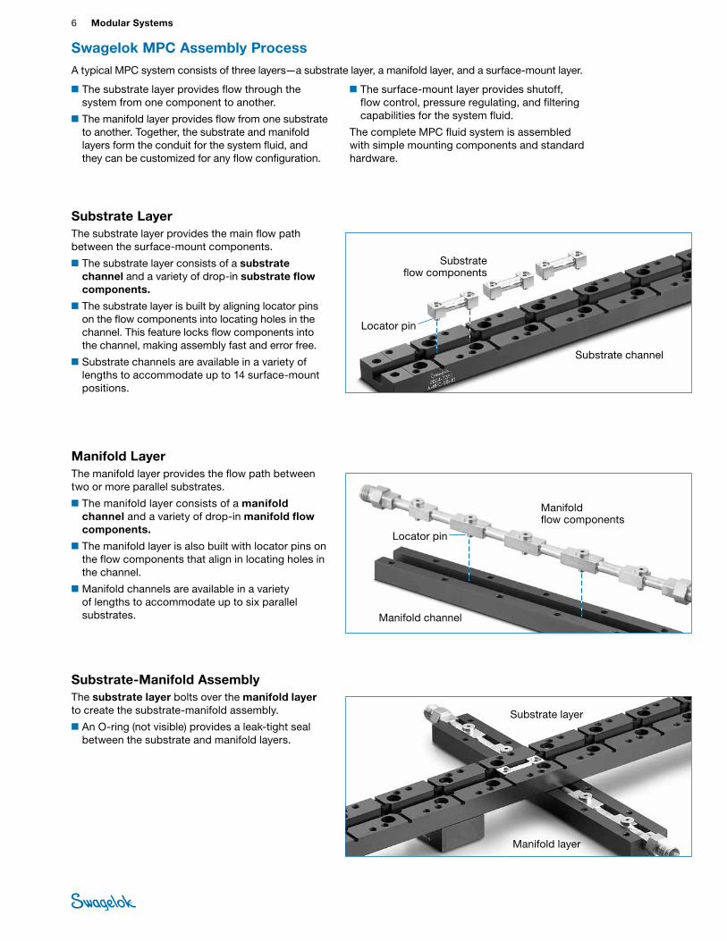
Substrate-Manifold AssemblyThe substrate layer bolts over the manifold layer to create the substrate-manifold assembly.
■An O-ring (not visible) provides a leak-tight seal between the substrate and manifold layers.
Manifold layer
Substrate layer
■The substrate layer provides flow through the system from one component to another.
■The manifold layer provides flow from one substrate to another. Together, the substrate and manifold layers form the conduit for the system fluid, and they can be customized for any flow configuration.
■The surface-mount layer provides shutoff, flow control, pressure regulating, and filtering capabilities for the system fluid.
The complete MPC fluid system is assembled with simple mounting components and standard hardware.
Manifold LayerThe manifold layer provides the flow path between two or more parallel substrates.
■The manifold layer consists of a manifold channel and a variety of drop-in manifold flow components.
■The manifold layer is also built with locator pins on the flow components that align in locating holes in the channel.
■Manifold channels are available in a variety of lengths to accommodate up to six parallel substrates.
Substrate LayerThe substrate layer provides the main flow path between the surface-mount components.
■The substrate layer consists of a substrate channel and a variety of drop-in substrate flow components.
■The substrate layer is built by aligning locator pins on the flow components into locating holes in the channel. This feature locks flow components into the channel, making assembly fast and error free.
■Substrate channels are available in a variety of lengths to accommodate up to 14 surface-mount positions.
Substrate flow components
Substrate channel
Locator pin
Manifold channel
Manifold flow components
Locator pin
Swagelok MPC Assembly ProcessA typical MPC system consists of three layers—a substrate layer, a manifold layer, and a surface-mount layer.

Modular Platform Components (MPC) 7 PIPE, W
ELD, VCR, VCO FITTINGS
STANDARD TUBING
MPC
COMPONENTS
HOSE / FLEXIBLE TUBING
BELLOWS,
DIAPHRAGM
VALVES
BALL & PLUG VALVES
CHECK & RELIEF VALVES
NEEDLE & M
ETERING VALVES
REGULATORS & FILTERS
INSTRUMENT
MANIFOLD
SYSTEMS
MEASUREM
ENT DEVICES
REFERENCESM
EDIUM- HIGH-
PRESSURETUBE
FITTINGS
Surface-Mount Adapters and CapsAdapters and caps are designed to bolt to the top of the substrate layer with the same footprint as a surface-mount component.
■Adapters provide a direct connection to the substrate layer and are available in several fitting styles and sizes to provide ANSI/ISA 76.00.02 interface for a variety of fluid control components.
■Caps cover and protect unused positions on the substrate layer.
■O-rings provide leak-tight seals.
Caps Adapters
Swagelok MPC Assembly Process
Mounting Blocks■Feet bolt to each end of the substrate layer,
providing panel-mount capability.
■Supports bolt underneath the substrate layer, providing mid-line support for longer substrates.
■Spacer feet bolt two substrate assemblies together end to end, maintaining standard surface-mount spacing between them.
Support
Spacer foot
Foot
Swagelok MPC ComponentsSwagelok surface-mount components are designed, manufactured, and tested to the same stringent quality requirements as conventional Swagelok fluid system components. They provide reliable Swagelok performance and value in a compact, ANSI/ISA 76.00.02-compliant interface.
Swagelok substrate flow components are made by butt welding two elbows together, elimininating entrapment zones and the need for O-ring seals between positions.This exclusive Swagelok design requires fewer O-ring seals than other modular platform systems, easing assembly and reducing the number of potential leak points.
Surface-Mount Layer
Surface-Mount ComponentsSurface-mount components, which feature all porting through a single surface, bolt to the top of the substrate-manifold assembly to complete the fluid system.
■O-rings provide leak-tight seals between surface-mount components and the substrate layer.
■Surface-mount components are available in a variety of shutoff, switching, metering, pressure regulating, and filtering styles with 2- or 3-port bodies.
■The porting and bolt pattern are open architecture, compliant with ANSI/ISA 76.00.02.
O-rings
Surface-mount component

8 Modular SystemsTU
BE
FITTI
NGS
PIPE
, WEL
D,
VCR,
VCO
FIT
TING
S
STAN
DARD
TU
BING
MPC
COM
PONE
NTS
HOSE
/ FL
EXIB
LE
TUBI
NG
BELL
OWS,
DI
APHR
AGM
VA
LVES
BALL
& P
LUG
VALV
ES
NEED
LE &
M
ETER
ING
VA
LVES
CHEC
K &
RELIE
F VA
LVES
REGU
LATO
RS
& FIL
TERS
INST
RUM
ENT
MAN
IFOLD
SY
STEM
S
MEA
SURE
MEN
T DE
VICE
SRE
FERE
NCES
MED
IUM
- HIG
H-
PRES
SURE
Swagelok MPC System ConfiguratorFeatures■Standard Windows menus and icon buttons
■Expandable grid for unlimited configurations
■Immediate output of standard fluid system calculations, such as pressure drop, flow rate, and Joule-Thomson cooling, based on a wide range of typical system gases and liquids
■Bill of material with itemized part numbers and assembly schematics that can be exported to a Microsoft® XPS document for easy file sharing
■Two-dimensional AutoCAD schematic and assembly files
■Three-dimensional SolidWorks models
For more information, contact your authorized Swagelok representative.
MPC system component selection and the assembly process are simplified with the use of the MPC System Configurator, a free Windows®-based software program that can be downloaded from your Swagelok website. The Configurator allows the user to create a customized system by defining, placing, and connecting surface-mount components on a layout grid.
Once the layout is complete, the Configurator identifies the MPC series flow connectors (including substrates, manifolds, seals, and assembly hardware) that are necessary to build the complete system. A bill of material is generated for ease of ordering components, and schematics are produced to facilitate assembly. The Configurator also integrates with the user’s AutoCAD® installation to create two-dimensional drawings and with the user’s SolidWorks® installation to produce three-dimensional solid models.
Configurator Bill of Material and Assembly Schematics Output
Three-Dimensional Model Output (requires user’s SolidWorks installation}
Two-Dimensional Schematic Output (requires user’s AutoCAD installation)
Swagelok MPC Configurator MPC Project Overview Page 1 of 5
Swagelok MPC System.mpcx
MPC Project Name Swagelok MPC System
Author BF
Company Name Swagelok
Date Friday, August 12, 2011
Notes Customer System 1
Combined Project Bill Of MaterialsID PN Description Qty
1 A-MPC-MB-01 MANIFOLD CHANNEL, MPC, 1 POSITION 1
2 A-MPC-SB-04 SUBSTRATE CHANNEL, MPC, 4 POSITIONS 2
3 A-MPC-SB-05 SUBSTRATE CHANNEL, MPC, 5 POSITIONS 1
4 A-MPC-SB-08 SUBSTRATE CHANNEL, MPC, 8 POSITIONS 1
5 6L-MPC-MS-MES2 MANIFOLD, MPC, ELBOW-TO-1/8 inch SWAGELOK TUBE FITTING, 1 POSITION 1
6 6L-MPC-WS-DD SUBSTRATE, MPC, DROP DOWN CONNECTOR, SUBSTRATE TO MANIFOLD 1
7 6L-MPC-WS-LGLG SUBSTRATE, MPC, CENTER, CENTER, 1.83" LONG 2
8 6L-MPC-WS-LGS4 SUBSTRATE END CONNECTOR, 1/4" SWAGELOK TUBE FITTING, CENTER 4
9 6L-MPC-WS-SHLG SUBSTRATE, MPC, SIDE, CENTER, 1.53" LONG 6
10 6L-MPC-WS-SHS2 SUBSTRATE END CONNECTOR, 1/8" SWAGELOK TUBE FITTING, SIDE 1
11 6L-MPC-WS-SHSH SUBSTRATE, MPC, SIDE, SIDE, 1.22" LONG 7
12 6L-MPC-WS-SHTB01LG JUMPER TUBE CONNECTOR, MPC, 1 POSITION, SIDE, CENTER, 3.06" LONG 1
13 A-MPC-MH-FOOT MOUNTING FOOT, MPC 8
14 A-MPC-MH-SPRT SUPPORT FOOT, MPC 2
15 FC-75-MPC-006 O-RING, FKM (qty 50 per bag) 1
16 SS-MPC-MH-0500 SOCKET HEAD CAP SCREW, 10-32 X 0.50 in. (20 per bag) 4
17 SS-MPC-MH-1000 SOCKET HEAD CAP SCREW, 10-32 X 1.00 in. (10 per bag) 2
18 SS-MPC-MH-LBAR LOCKDOWN BAR, MPC 8
19 KCP1EJ5MA2P10000 PRESSURE REGULATOR, KCP SERIES, 316 SS, 0 to 50 psig (0 to 3.4 bar), 500 psig (34.4 bar) MAX INLET, 2 PORT, MPC, FKM, 0.06 Cv 2
20 PGI-40M-PG100-CAQX PRESSURE GAUGE, 40M, PRIMARY: psi SECONDARY: bar, 0 to 100 psi, 1/4 in. TUBE FITTING 4
21 SS-MPC-42T-2 MANUAL BALL VALVE, 42T SERIES, 2 PORT 4
22 SS-MPC-4TF-2-15 FILTER, TEE-TYPE, TF SERIES, 15 µm PORE SIZE 4
23 SS-MPC-DM-2-S4 SURFACE MOUNT ADAPTER, 2-PORT, SWAGELOK TUBE FITTING 1/4 in. 4
24 SS-MPC-M-2-SL METERING VALVE, 2 PORT, SLOTTED HANDLE 1
25 SS-MPC-PSV-3-CC THREE WAY PNEUMATIC VALVE, COMMON CENTER PORT 1
26 SS-SSV-V-4-MPC STREAM SELECTOR VALVE, 4 STREAMS, FKM SEALS 1
The Assembly Diagram and Bill of Material identify the MPC footprint and/or materials of the connecting fluid conduits and components submitted by the end-user's design schematic and process flow diagram. Please verify the accuracy. The assembly, design, and application are the express, sole responsibility of the end-user, and materials purchaser.
System 1Schematic Diagram
The Assembly Diagram and Bill of Material identify the MPC footprint and/or materials of the connecting fluid conduits and components submitted by the end-user's design schematic and process flow diagram. Please verify the accuracy. The assembly, design, and application are the express, sole responsibility of the end-user, and materials purchaser.
Swagelok MPC Configurator MPC Project Overview Page 2 of 5
Project
Component LayerSystem 1
The Assembly Diagram and Bill of Material identify the MPC footprint and/or materials of the connecting fluid conduits and components submitted by the end-user's design schematic and process flow diagram. Please verify the accuracy. The assembly, design, and application are the express, sole responsibility of the end-user, and materials purchaser.
Swagelok MPC Configurator MPC Project Overview Page 3 of 5
Project
Modular Platform Components (MPC) 9 PIPE, W
ELD, VCR, VCO FITTINGS
STANDARD TUBING
MPC
COMPONENTS
HOSE / FLEXIBLE TUBING
BELLOWS,
DIAPHRAGM
VALVES
BALL & PLUG VALVES
CHECK & RELIEF VALVES
NEEDLE & M
ETERING VALVES
REGULATORS & FILTERS
INSTRUMENT
MANIFOLD
SYSTEMS
MEASUREM
ENT DEVICES
REFERENCESM
EDIUM- HIGH-
PRESSURETUBE
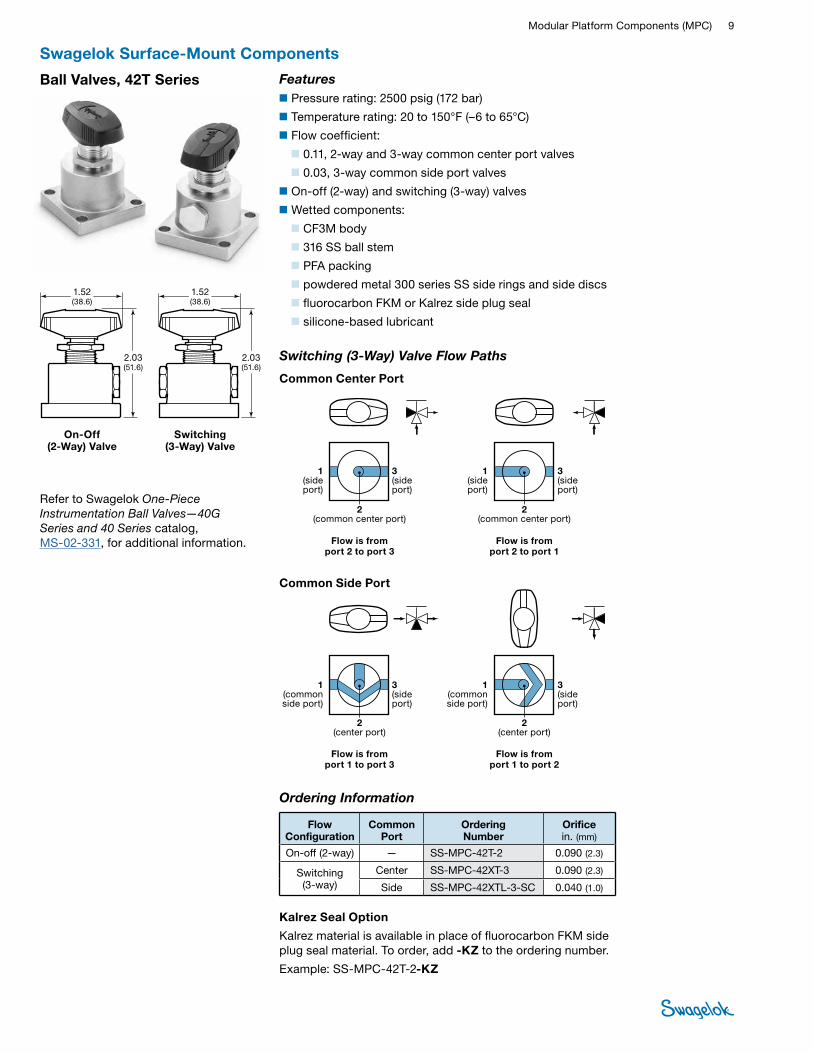
FITTINGSBall Valves, 42T Series Features■Pressure rating: 2500 psig (172 bar)
■Temperature rating: 20 to 150°F (–6 to 65°C)
■Flow coefficient:
■0.11, 2-way and 3-way common center port valves
■0.03, 3-way common side port valves
■On-off (2-way) and switching (3-way) valves
■Wetted components:
■ CF3M body
■ 316 SS ball stem
■ PFA packing
■ powdered metal 300 series SS side rings and side discs
■ fluorocarbon FKM or Kalrez side plug seal
■ silicone-based lubricant
2.03 (51.6)
1.52 (38.6)
2.03 (51.6)
1.52 (38.6)
On-Off (2-Way) Valve
Switching (3-Way) Valve
Refer to Swagelok One-Piece Instrumentation Ball Valves—40G Series and 40 Series catalog, MS-02-331, for additional information.
Swagelok Surface-Mount Components
Ordering Information
Flow Configuration
Common Port
Ordering Number
Orifice in. (mm)
On-off (2-way) — SS-MPC-42T-2 0.090 (2.3)
Switching (3-way)
Center SS-MPC-42XT-3 0.090 (2.3)
Side SS-MPC-42XTL-3-SC 0.040 (1.0)
Kalrez Seal Option
Kalrez material is available in place of fluorocarbon FKM side plug seal material. To order, add -KZ to the ordering number.
Example: SS-MPC-42T-2-KZ
Switching (3-Way) Valve Flow Paths
Flow is from port 2 to port 3
1 (side port)
3 (side port)
1 (side port)
3 (side port)
2 (common center port)
Common Center Port
Common Side Port
Flow is from port 2 to port 1
Flow is from port 1 to port 3
1 (common side port)
1 (common side port)
3 (side port)
2 (center port)
Flow is from port 1 to port 2
2 (center port)
2 (common center port)
3 (side port)
10 Modular SystemsTU
BE
FITTI
NGS
PIPE
, WEL
D,
VCR,
VCO
FIT
TING
S
STAN
DARD
TU
BING
MPC
COM
PONE
NTS
HOSE
/ FL
EXIB
LE
TUBI
NG
BELL
OWS,
DI
APHR
AGM
VA
LVES
BALL
& P
LUG
VALV
ES
NEED
LE &
M
ETER
ING
VA
LVES
CHEC
K &
RELIE
F VA
LVES
REGU
LATO
RS
& FIL
TERS
INST
RUM
ENT
MAN
IFOLD
SY
STEM
S
MEA
SURE
MEN
T DE
VICE
SRE
FERE
NCES
MED
IUM
- HIG
H-
PRES
SURE
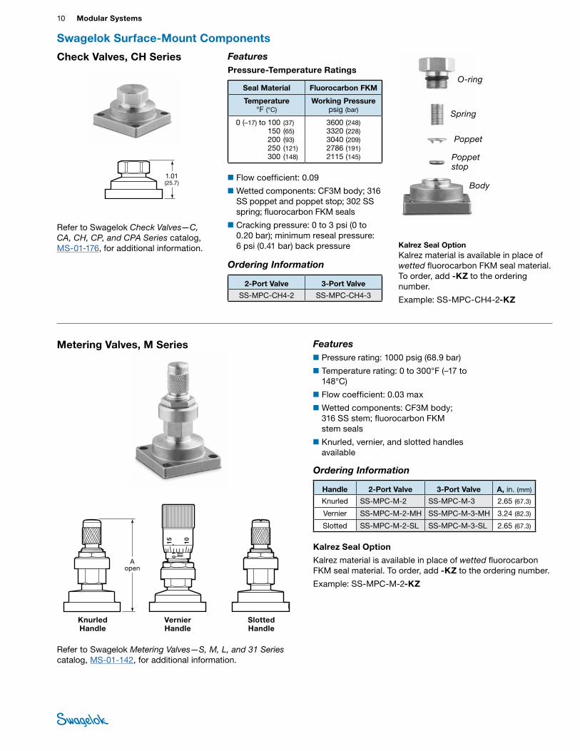
Check Valves, CH Series FeaturesPressure-Temperature Ratings
Seal Material Fluorocarbon FKM
Temperature °F (°C)
Working Pressure psig (bar)
0 (–17) to 100 (37) 150 (65) 200 (93) 250 (121) 300 (148)
3600 (248)3320 (228)3040 (209)2786 (191)2115 (145)
■Flow coefficient: 0.09
■Wetted components: CF3M body; 316 SS poppet and poppet stop; 302 SS spring; fluorocarbon FKM seals
■Cracking pressure: 0 to 3 psi (0 to 0.20 bar); minimum reseal pressure: 6 psi (0.41 bar) back pressure
Ordering Information
2-Port Valve 3-Port Valve
SS-MPC-CH4-2 SS-MPC-CH4-3
Refer to Swagelok Check Valves—C, CA, CH, CP, and CPA Series catalog, MS-01-176, for additional information.
1.01 (25.7) Body
Poppet stop
Poppet
Spring
O-ring
Swagelok Surface-Mount Components
Kalrez Seal OptionKalrez material is available in place of wetted fluorocarbon FKM seal material. To order, add -KZ to the ordering number.
Example: SS-MPC-CH4-2-KZ
Metering Valves, M Series
Refer to Swagelok Metering Valves—S, M, L, and 31 Series catalog, MS-01-142, for additional information.
Features■Pressure rating: 1000 psig (68.9 bar)
■Temperature rating: 0 to 300°F (–17 to 148°C)
■Flow coefficient: 0.03 max
■Wetted components: CF3M body; 316 SS stem; fluorocarbon FKM stem seals
■Knurled, vernier, and slotted handles available
Knurled Handle
A open
Vernier Handle
Slotted Handle
Ordering Information
Handle 2-Port Valve 3-Port Valve A, in. (mm)
Knurled SS-MPC-M-2 SS-MPC-M-3 2.65 (67.3)
Vernier SS-MPC-M-2-MH SS-MPC-M-3-MH 3.24 (82.3)
Slotted SS-MPC-M-2-SL SS-MPC-M-3-SL 2.65 (67.3)
Kalrez Seal Option
Kalrez material is available in place of wetted fluorocarbon FKM seal material. To order, add -KZ to the ordering number.
Example: SS-MPC-M-2-KZ
Modular Platform Components (MPC) 11 PIPE, W
ELD, VCR, VCO FITTINGS
STANDARD TUBING
MPC
COMPONENTS
HOSE / FLEXIBLE TUBING
BELLOWS,
DIAPHRAGM
VALVES
BALL & PLUG VALVES
CHECK & RELIEF VALVES
NEEDLE & M
ETERING VALVES
REGULATORS & FILTERS
INSTRUMENT
MANIFOLD
SYSTEMS
MEASUREM
ENT DEVICES
REFERENCESM
EDIUM- HIGH-
PRESSURETUBE
FITTINGS
Toggle Valves, OG Series Features■Pressure rating: 300 psig (20.6 bar)
■Temperature rating: 0 to 200°F (–17 to 93°C)
■Flow coefficient: 0.11
■Wetted components: CF3M body; 316 SS stem; PTFE stem tip; fluorocarbon FKM stem seal
■Toggle handle is rotatable to desired position.
■Handle positioner option allows fixed positioning of handle.
■Spring-return pin option helps prevent handle from being locked open.
Ordering Information
2-Port Valve 3-Port Valve
SS-MPC-OG-2 SS-MPC-OG-3
Refer to Swagelok Toggle Valves—OG and 1G Series catalog, MS-01-54, for additional information.
2.94 (74.7) open
1.95 (49.5)
closed
2.03 (51.6)
Handle Color Option
Standard handle color is black. To order an optional color, add a color designator to the ordering number.
Example: SS-MPC-OG-2-RD
Handle Positioner Option
To order, add -TGP to the ordering number.
Example: SS-MPC-OG-2-TGP
Spring-Return Pin Option
To order, add -SPR to the ordering number.
Example: SS-MPC-OG-2-SPR
Kalrez Seal Option
Kalrez material is available in place of wetted fluorocarbon FKM seal material. To order, add -KZ to the ordering number.
Example: SS-MPC-OG-2-KZ
Multiple Options
Add designators in alphabetical order. Example: SS-MPC-OG-2-GR-KZ-TGP
Color Designator
Blue -BL
Green -GR
Orange -OG
Red -RD
Yellow -YW
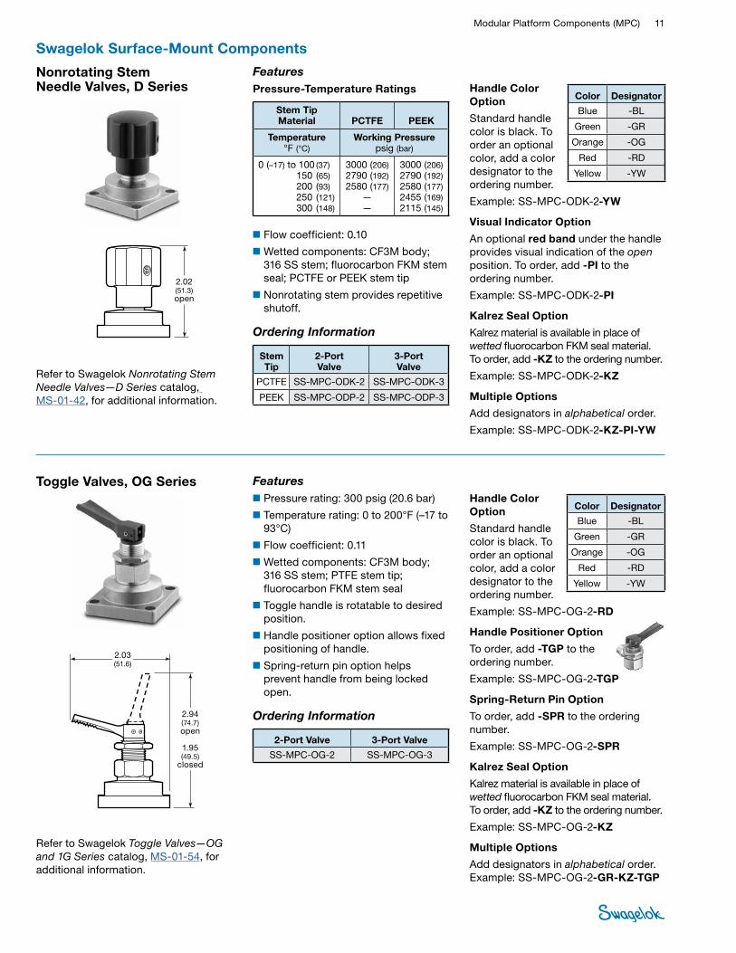
Nonrotating Stem Needle Valves, D Series
Refer to Swagelok Nonrotating Stem Needle Valves—D Series catalog, MS-01-42, for additional information.
FeaturesPressure-Temperature Ratings
Stem Tip Material PCTFE PEEK
Temperature °F (°C)
Working Pressure psig (bar)
0 (–17) to 100 (37) 150 (65) 200 (93) 250 (121) 300 (148)
3000 (206)2790 (192)2580 (177)
——
3000 (206)2790 (192)2580 (177)2455 (169)2115 (145)
■Flow coefficient: 0.10
■Wetted components: CF3M body; 316 SS stem; fluorocarbon FKM stem seal; PCTFE or PEEK stem tip
■Nonrotating stem provides repetitive shutoff.
Ordering Information
Stem Tip
2-Port Valve
3-Port Valve
PCTFE SS-MPC-ODK-2 SS-MPC-ODK-3
PEEK SS-MPC-ODP-2 SS-MPC-ODP-3
2.02 (51.3) open
Handle Color Option
Standard handle color is black. To order an optional color, add a color designator to the ordering number.
Example: SS-MPC-ODK-2-YW
Visual Indicator Option
An optional red band under the handle provides visual indication of the open position. To order, add -PI to the ordering number.
Example: SS-MPC-ODK-2-PI
Kalrez Seal Option
Kalrez material is available in place of wetted fluorocarbon FKM seal material. To order, add -KZ to the ordering number.
Example: SS-MPC-ODK-2-KZ
Multiple Options
Add designators in alphabetical order.
Example: SS-MPC-ODK-2-KZ-PI-YW
Color Designator
Blue -BL
Green -GR
Orange -OG
Red -RD
Yellow -YW
Swagelok Surface-Mount Components
12 Modular SystemsTU
BE
FITTI
NGS
PIPE
, WEL
D,
VCR,
VCO
FIT
TING
S
STAN
DARD
TU
BING
MPC
COM
PONE
NTS
HOSE
/ FL
EXIB
LE
TUBI
NG
BELL
OWS,
DI
APHR
AGM
VA
LVES
BALL
& P
LUG
VALV
ES
NEED
LE &
M
ETER
ING
VA
LVES
CHEC
K &
RELIE
F VA
LVES
REGU
LATO
RS
& FIL
TERS
INST
RUM
ENT
MAN
IFOLD
SY
STEM
S
MEA
SURE
MEN
T DE
VICE
SRE
FERE
NCES
MED
IUM
- HIG
H-
PRES
SURE
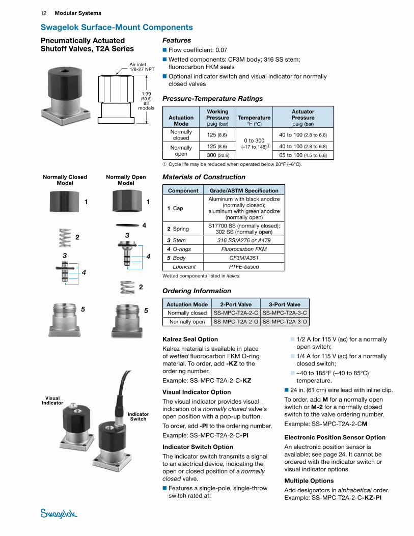
Pneumatically Actuated Shutoff Valves, T2A Series
Features■Flow coefficient: 0.07
■Wetted components: CF3M body; 316 SS stem; fluorocarbon FKM seals
■Optional indicator switch and visual indicator for normally closed valves
Materials of Construction
Component Grade/ASTM Specification
1 Cap
Aluminum with black anodize (normally closed);
aluminum with green anodize (normally open)
2 Spring S17700 SS (normally closed); 302 SS (normally open)
3 Stem 316 SS/A276 or A479
4 O-rings Fluorocarbon FKM
5 Body CF3M/A351
Lubricant PTFE-based
Wetted components listed in italics.
Pressure-Temperature Ratings
Actuation Mode
Working Pressure psig (bar)
Temperature °F (°C)
Actuator Pressure psig (bar)
Normally closed 125 (8.6)
0 to 300 (–17 to 148)➀
40 to 100 (2.8 to 6.8)
Normally open
125 (8.6) 40 to 100 (2.8 to 6.8)
300 (20.6) 65 to 100 (4.5 to 6.8)
➀ Cycle life may be reduced when operated below 20°F (–6°C).
Normally Closed Model
Normally Open Model
1
2
3
5
4
1
2
3
5
4
4
Swagelok Surface-Mount Components
Ordering Information
Actuation Mode 2-Port Valve 3-Port Valve
Normally closed SS-MPC-T2A-2-C SS-MPC-T2A-3-C
Normally open SS-MPC-T2A-2-O SS-MPC-T2A-3-O
Kalrez Seal Option
Kalrez material is available in place of wetted fluorocarbon FKM O-ring material. To order, add -KZ to the ordering number.
Example: SS-MPC-T2A-2-C-KZ
Visual Indicator Option
The visual indicator provides visual indication of a normally closed valve’s open position with a pop-up button.
To order, add -PI to the ordering number.
Example: SS-MPC-T2A-2-C-PI
Indicator Switch Option
The indicator switch transmits a signal to an electrical device, indicating the open or closed position of a normally closed valve.
■Features a single-pole, single-throw switch rated at:
■1/2 A for 115 V (ac) for a normally open switch;
■1/4 A for 115 V (ac) for a normally closed switch;
■–40 to 185°F (–40 to 85°C) temperature.
■24 in. (61 cm) wire lead with inline clip.
To order, add M for a normally open switch or M-2 for a normally closed switch to the valve ordering number.
Example: SS-MPC-T2A-2-CM
Electronic Position Sensor Option
An electronic position sensor is available; see page 24. It cannot be ordered with the indicator switch or visual indicator options.
Multiple Options
Add designators in alphabetical order. Example: SS-MPC-T2A-2-C-KZ-PI
Air inlet 1/8-27 NPT
1.99 (50.5)
all models
Visual Indicator
Indicator Switch

Modular Platform Components (MPC) 13 PIPE, W
ELD, VCR, VCO FITTINGS
STANDARD TUBING
MPC
COMPONENTS
HOSE / FLEXIBLE TUBING
BELLOWS,
DIAPHRAGM
VALVES
BALL & PLUG VALVES
CHECK & RELIEF VALVES
NEEDLE & M
ETERING VALVES
REGULATORS & FILTERS
INSTRUMENT
MANIFOLD
SYSTEMS
MEASUREM
ENT DEVICES
REFERENCESM
EDIUM- HIGH-
PRESSURETUBE
FITTINGSPneumatically Actuated Switching Valves, PSV Series
Pressure-Temperature Ratings
Working Pressure psig (bar)
Temperature ºF (ºC)
Actuator Pressure psig (bar)
300 (20.6) 0 to 300 (–17 to 148)
40 to 100 (2.8 to 6.8)
Materials of Construction
ComponentGrade/ASTM Specification
1 Cap Aluminum
2 Spring S17700
3 Piston Aluminum
4 Bonnet cylinder 316 SS/A276
5 O-rings Fluorocarbon FKM
6 Stem 316 SS/A276
7 Body CF3M/A351
Lubricant PTFE-based
Wetted components listed in italics.
2.86 (76.2)
Features■Flow coefficient: 0.06
■Wetted components: CF3M body; 316 SS stem and bonnet cylinder; fluorocarbon FKM seals
■Optional visual indicator
1
2
3
54
6
7
Swagelok Surface-Mount Components
Kalrez Seal Option
Kalrez material is available in place of wetted fluorocarbon FKM O-ring material. To order, add -KZ to the ordering number.
Example: SS-MPC-PSV-3-CC-KZ
Visual Indicator Option
The visual indicator provides a visual indication of the open position of the valve with a pop-up button. To order, add -PI to the ordering number.
Example: SS-MPC-PSV-3-CC-PI
Electronic Position Sensor Option
An electronic position sensor is available; see page 24. It cannot be ordered with the visual indicator option.
Ordering Information
Common Port Ordering Number
Center SS-MPC-PSV-3-CC
Side SS-MPC-PSV-3-SC
Visual Indicator
Switching Valve Flow Paths
Normal Actuated
Flow Schematics
Flow is from
common to NO
Flow is from
common to NC
NC
NO
CO
MM
ON
Bottom
Common Center Port
Common Side Port
Normal Actuated
Flow Schematics
Flow is from
common to NO
Flow is from
common to NC
CO
MM
ON
NC
NO
Bottom
Air inlet 1/8-27 NPT
Multiple Options
Add designators in alphabetical order. Example: SS-MPC-PSV-3-CC-KZ-P
14 Modular SystemsTU
BE
FITTI
NGS
PIPE
, WEL
D,
VCR,
VCO
FIT
TING
S
STAN
DARD
TU
BING
MPC
COM
PONE
NTS
HOSE
/ FL
EXIB
LE
TUBI
NG
BELL
OWS,
DI
APHR
AGM
VA
LVES
BALL
& P
LUG
VALV
ES
NEED
LE &
M
ETER
ING
VA
LVES
CHEC
K &
RELIE
F VA
LVES
REGU
LATO
RS
& FIL
TERS
INST
RUM
ENT
MAN
IFOLD
SY
STEM
S
MEA
SURE
MEN
T DE
VICE
SRE
FERE
NCES
MED
IUM
- HIG
H-
PRES
SURE
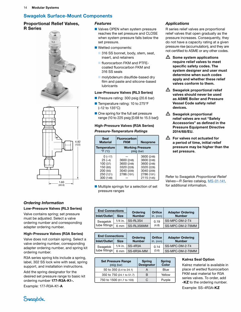
Proportional Relief Valves, R Series
Refer to Swagelok Proportional Relief Valves—R Series catalog, MS-01-141, for additional information.
Ordering InformationLow-Pressure Valves (RL3 Series)
Valve contains spring; set pressure must be adjusted. Select a valve ordering number and corresponding adapter ordering number.
High-Pressure Valves (R3A Series)
Valve does not contain spring. Select a valve ordering number, corresponding adapter ordering number, and spring kit ordering number.
R3A series spring kits include a spring, label, 302 SS lock wire with seal, spring support, and installation instructions.
Add the spring designator for the desired set pressure range to basic kit ordering number 177-R3A-K1-.
Example: 177-R3A-K1-A
Set Pressure Range psig (bar)
Spring Designator
Spring Color
50 to 350 (3.4 to 24.1) A Blue
350 to 750 (24.1 to 51.7) B Yellow
750 to 1500 (51.7 to 103) C Purple
End Connections Ordering Number
Orifice in. (mm)
Adapter Ordering NumberInlet/Outlet Size
Swagelok tube fittings
1/4 in. SS-RL3S4 0.19 (4.8)
SS-MPC-DM-2-T4
6 mm SS-RL3S6MM SS-MPC-DM-2-T6MM
End Connections Ordering Number
Orifice in. (mm)
Adapter Ordering NumberInlet/Outlet Size
Swagelok tube fittings
1/4 in. SS-4R3A 0.14 (3.6)
SS-MPC-DM-2-T4
6 mm SS-6R3A-MM SS-MPC-DM-2-T6MM
Features■Valves OPEN when system pressure
reaches the set pressure and CLOSE when system pressure falls below the set pressure.
■Wetted components:
■ 316 SS bonnet, body, stem, seat, insert, and retainers
■ fluorocarbon FKM and PTFE-coated fluorocarbon FKM and 316 SS seals
■ molybdenum disulfide-based dry film and paste and silicone-based lubricants
Low-Pressure Valves (RL3 Series)
■Pressure rating: 300 psig (20.6 bar)
■Temperature rating: 10 to 275°F (–12 to 135°C)
■One spring for the full set pressure range (10 to 225 psig [0.68 to 15.5 bar])
High-Pressure Valves (R3A Series)
Pressure-Temperature Ratings
Seal Material
Fluorocarbon FKM Neoprene
Temperature °F (°C)
Working Pressure psig (bar)
0 (–17)25 (–4)
100 (37)150 (65)200 (93)250 (121)300 (148)
—3600 (248)3600 (248)3320 (228)3040 (209)2786 (191)
—
3600 (248)3600 (248)3600 (248)3320 (228)3040 (209)2786 (191)2115 (145)
■Multiple springs for a selection of set pressure ranges
Swagelok Surface-Mount Components
1.60 (40.6)
4.82 (122)
Kalrez Seal Option
Kalrez material is available in place of wetted fluorocarbon FKM seal material for R3A series valves. To order, add -KZ to the ordering number.
Example: SS-4R3A-KZ
ApplicationsR series relief valves are proportional relief valves that open gradually as the pressure increases. Consequently, they do not have a capacity rating at a given pressure rise (accumulation), and they are not certified to ASME or any other codes.
• Some system applications require relief valves to meet specific safety codes. The system designer and user must determine when such codes apply and whether these relief valves conform to them.
• Swagelok proportional relief valves should never be used as ASME Boiler and Pressure Vessel Code safety relief devices.
• Swagelok proportional relief valves are not “Safety Accessories” as defined in the Pressure Equipment Directive 2014/68/EU.
• For valves not actuated for a period of time, initial relief pressure may be higher than the set pressure.
Modular Platform Components (MPC) 15 PIPE, W
ELD, VCR, VCO FITTINGS
STANDARD TUBING
MPC
COMPONENTS
HOSE / FLEXIBLE TUBING
BELLOWS,
DIAPHRAGM
VALVES
BALL & PLUG VALVES
CHECK & RELIEF VALVES
NEEDLE & M
ETERING VALVES
REGULATORS & FILTERS
INSTRUMENT
MANIFOLD
SYSTEMS
MEASUREM
ENT DEVICES
REFERENCESM
EDIUM- HIGH-
PRESSURETUBE
FITTINGS
Refer to Swagelok Springless Diaphragm Valves for High Performance—DP Series catalog, MS-01-165, for additional information.
Integral Lockout Handle
Directional Handle
3.18 (80.8) open
3.51 (89.2)
closed/locked
2.28 (57.9) open
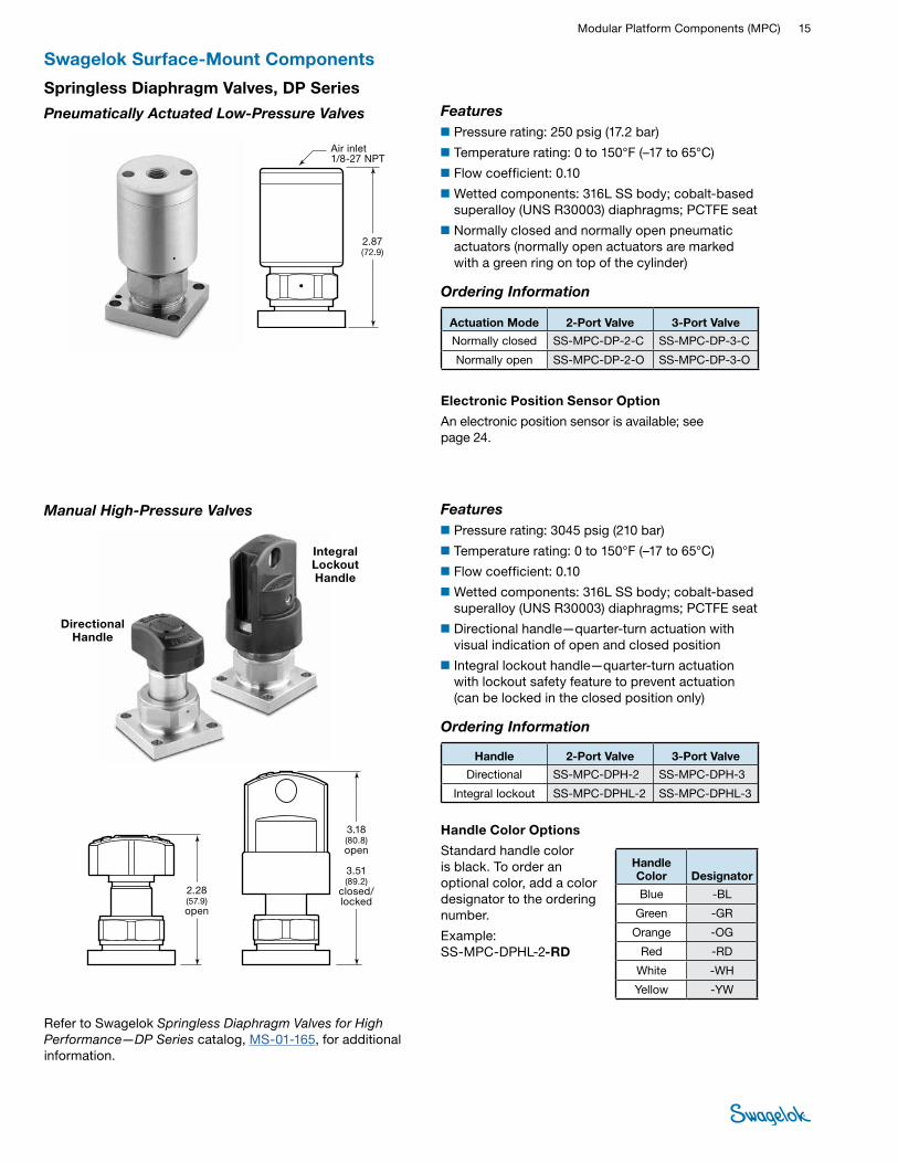
Springless Diaphragm Valves, DP Series
Pneumatically Actuated Low-Pressure Valves
Manual High-Pressure Valves
Features■Pressure rating: 250 psig (17.2 bar)
■Temperature rating: 0 to 150°F (–17 to 65°C)
■Flow coefficient: 0.10
■Wetted components: 316L SS body; cobalt-based superalloy (UNS R30003) diaphragms; PCTFE seat
■Normally closed and normally open pneumatic actuators (normally open actuators are marked with a green ring on top of the cylinder)
Ordering Information
Actuation Mode 2-Port Valve 3-Port Valve
Normally closed SS-MPC-DP-2-C SS-MPC-DP-3-C
Normally open SS-MPC-DP-2-O SS-MPC-DP-3-O
Electronic Position Sensor Option
An electronic position sensor is available; see page 24.
2.87 (72.9)
Air inlet 1/8-27 NPT
Swagelok Surface-Mount Components
Features■Pressure rating: 3045 psig (210 bar)
■Temperature rating: 0 to 150°F (–17 to 65°C)
■Flow coefficient: 0.10
■Wetted components: 316L SS body; cobalt-based superalloy (UNS R30003) diaphragms; PCTFE seat
■Directional handle—quarter-turn actuation with visual indication of open and closed position
■Integral lockout handle—quarter-turn actuation with lockout safety feature to prevent actuation (can be locked in the closed position only)
Ordering Information
Handle 2-Port Valve 3-Port Valve
Directional SS-MPC-DPH-2 SS-MPC-DPH-3
Integral lockout SS-MPC-DPHL-2 SS-MPC-DPHL-3
Handle Color Options
Standard handle color is black. To order an optional color, add a color designator to the ordering number.
Example: SS-MPC-DPHL-2-RD
Handle Color Designator
Blue -BL
Green -GR
Orange -OG
Red -RD
White -WH
Yellow -YW
16 Modular SystemsTU
BE
FITTI
NGS
PIPE
, WEL
D,
VCR,
VCO
FIT
TING
S
STAN
DARD
TU
BING
MPC
COM
PONE
NTS
HOSE
/ FL
EXIB
LE
TUBI
NG
BELL
OWS,
DI
APHR
AGM
VA
LVES
BALL
& P
LUG
VALV
ES
NEED
LE &
M
ETER
ING
VA
LVES
CHEC
K &
RELIE
F VA
LVES
REGU
LATO
RS
& FIL
TERS
INST
RUM
ENT
MAN
IFOLD
SY
STEM
S
MEA
SURE
MEN
T DE
VICE
SRE
FERE
NCES
MED
IUM
- HIG
H-
PRES
SURE
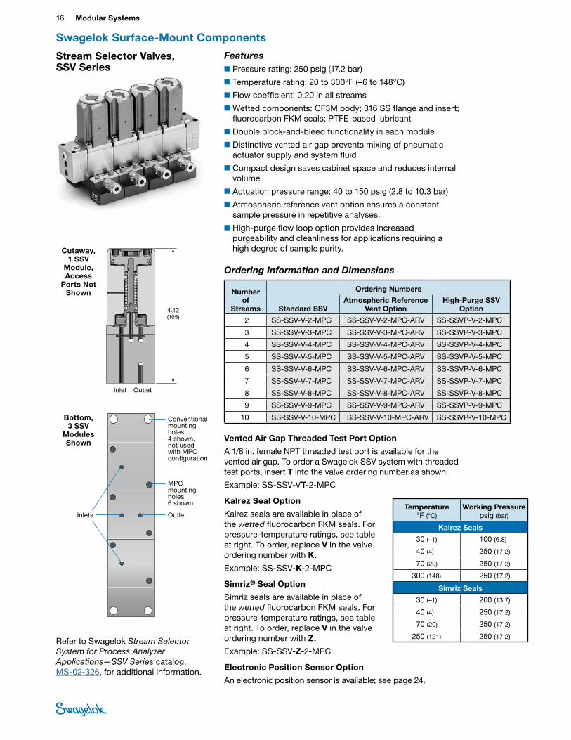
Stream Selector Valves, SSV Series
Inlets Outlet
MPC mounting holes, 6 shown
Refer to Swagelok Stream Selector System for Process Analyzer Applications—SSV Series catalog, MS-02-326, for additional information.
Swagelok Surface-Mount Components
Conventional mounting holes, 4 shown, not used with MPC configuration
Inlet Outlet
4.12 (105)
Bottom, 3 SSV
Modules Shown
Cutaway, 1 SSV
Module, Access
Ports Not Shown
Vented Air Gap Threaded Test Port Option
A 1/8 in. female NPT threaded test port is available for the vented air gap. To order a Swagelok SSV system with threaded test ports, insert T into the valve ordering number as shown.
Example: SS-SSV-VT-2-MPC
Kalrez Seal Option
Kalrez seals are available in place of the wetted fluorocarbon FKM seals. For pressure-temperature ratings, see table at right. To order, replace V in the valve ordering number with K.
Example: SS-SSV-K-2-MPC
Simriz® Seal Option
Simriz seals are available in place of the wetted fluorocarbon FKM seals. For pressure-temperature ratings, see table at right. To order, replace V in the valve ordering number with Z.
Example: SS-SSV-Z-2-MPC
Electronic Position Sensor Option
An electronic position sensor is available; see page 24.
Temperature °F (°C)
Working Pressure psig (bar)
Kalrez Seals
30 (–1) 100 (6.8)
40 (4) 250 (17.2)
70 (20) 250 (17.2)
300 (148) 250 (17.2)
Simriz Seals
30 (–1) 200 (13.7)
40 (4) 250 (17.2)
70 (20) 250 (17.2)
250 (121) 250 (17.2)
Ordering Information and Dimensions
Number of
Streams
Ordering Numbers
Standard SSVAtmospheric Reference
Vent OptionHigh-Purge SSV
Option
2 SS-SSV-V-2-MPC SS-SSV-V-2-MPC-ARV SS-SSVP-V-2-MPC
3 SS-SSV-V-3-MPC SS-SSV-V-3-MPC-ARV SS-SSVP-V-3-MPC
4 SS-SSV-V-4-MPC SS-SSV-V-4-MPC-ARV SS-SSVP-V-4-MPC
5 SS-SSV-V-5-MPC SS-SSV-V-5-MPC-ARV SS-SSVP-V-5-MPC
6 SS-SSV-V-6-MPC SS-SSV-V-6-MPC-ARV SS-SSVP-V-6-MPC
7 SS-SSV-V-7-MPC SS-SSV-V-7-MPC-ARV SS-SSVP-V-7-MPC
8 SS-SSV-V-8-MPC SS-SSV-V-8-MPC-ARV SS-SSVP-V-8-MPC
9 SS-SSV-V-9-MPC SS-SSV-V-9-MPC-ARV SS-SSVP-V-9-MPC
10 SS-SSV-V-10-MPC SS-SSV-V-10-MPC-ARV SS-SSVP-V-10-MPC
Features■Pressure rating: 250 psig (17.2 bar)
■Temperature rating: 20 to 300°F (–6 to 148°C)
■Flow coefficient: 0.20 in all streams
■Wetted components: CF3M body; 316 SS flange and insert; fluorocarbon FKM seals; PTFE-based lubricant
■Double block-and-bleed functionality in each module
■Distinctive vented air gap prevents mixing of pneumatic actuator supply and system fluid
■Compact design saves cabinet space and reduces internal volume
■Actuation pressure range: 40 to 150 psig (2.8 to 10.3 bar)
■Atmospheric reference vent option ensures a constant sample pressure in repetitive analyses.
■High-purge flow loop option provides increased purgeability and cleanliness for applications requiring a high degree of sample purity.
Modular Platform Components (MPC) 17 PIPE, W
ELD, VCR, VCO FITTINGS
STANDARD TUBING
MPC
COMPONENTS
HOSE / FLEXIBLE TUBING
BELLOWS,
DIAPHRAGM
VALVES
BALL & PLUG VALVES
CHECK & RELIEF VALVES
NEEDLE & M
ETERING VALVES
REGULATORS & FILTERS
INSTRUMENT
MANIFOLD
SYSTEMS
MEASUREM
ENT DEVICES
REFERENCESM
EDIUM- HIGH-
PRESSURETUBE
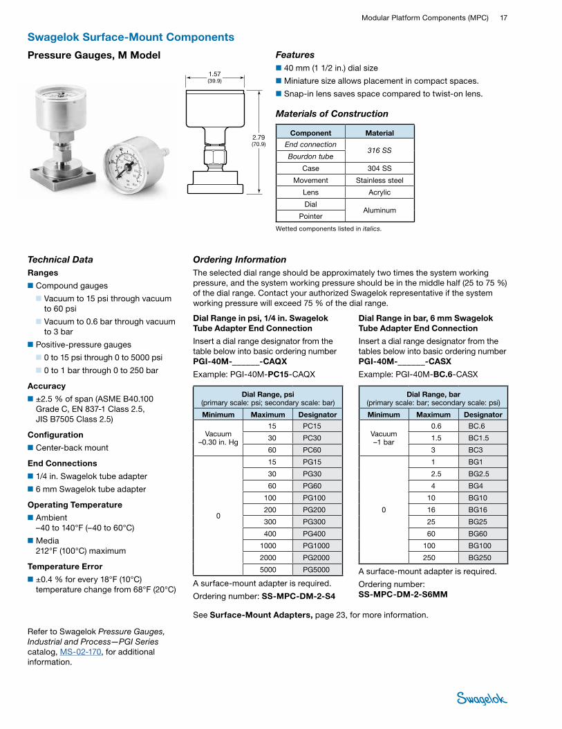
FITTINGSFeatures■40 mm (1 1/2 in.) dial size
■Miniature size allows placement in compact spaces.
■Snap-in lens saves space compared to twist-on lens.
Pressure Gauges, M Model
Refer to Swagelok Pressure Gauges, Industrial and Process—PGI Series catalog, MS-02-170, for additional information.
Materials of Construction
Wetted components listed in italics.
Component Material
End connection 316 SS
Bourdon tube
Case 304 SS
Movement Stainless steel
Lens Acrylic
Dial Aluminum
Pointer
Swagelok Surface-Mount Components
Technical DataRanges
■Compound gauges
■ Vacuum to 15 psi through vacuum to 60 psi
■ Vacuum to 0.6 bar through vacuum to 3 bar
■Positive-pressure gauges
■ 0 to 15 psi through 0 to 5000 psi
■ 0 to 1 bar through 0 to 250 bar
Accuracy
■±2.5 % of span (ASME B40.100 Grade C, EN 837-1 Class 2.5, JIS B7505 Class 2.5)
Configuration
■Center-back mount
End Connections
■1/4 in. Swagelok tube adapter
■6 mm Swagelok tube adapter
Operating Temperature
■Ambient –40 to 140°F (–40 to 60°C)
■Media 212°F (100°C) maximum
Temperature Error
■±0.4 % for every 18°F (10°C) temperature change from 68°F (20°C)
Dial Range in psi, 1/4 in. Swagelok Tube Adapter End Connection
Insert a dial range designator from the table below into basic ordering number PGI-40M-______-CAQX
Example: PGI-40M-PC15-CAQX
A surface-mount adapter is required.
Ordering number: SS-MPC-DM-2-S4
Dial Range, psi (primary scale: psi; secondary scale: bar)
Minimum Maximum Designator
Vacuum –0.30 in. Hg
15 PC15
30 PC30
60 PC60
0
15 PG15
30 PG30
60 PG60
100 PG100
200 PG200
300 PG300
400 PG400
1000 PG1000
2000 PG2000
5000 PG5000
Dial Range, bar (primary scale: bar; secondary scale: psi)
Minimum Maximum Designator
Vacuum –1 bar
0.6 BC.6
1.5 BC1.5
3 BC3
0
1 BG1
2.5 BG2.5
4 BG4
10 BG10
16 BG16
25 BG25
60 BG60
100 BG100
250 BG250
Ordering InformationThe selected dial range should be approximately two times the system working pressure, and the system working pressure should be in the middle half (25 to 75 %) of the dial range. Contact your authorized Swagelok representative if the system working pressure will exceed 75 % of the dial range.
Dial Range in bar, 6 mm Swagelok Tube Adapter End Connection
Insert a dial range designator from the tables below into basic ordering number PGI-40M-______-CASX
Example: PGI-40M-BC.6-CASX
A surface-mount adapter is required.
Ordering number: SS-MPC-DM-2-S6MM
See Surface-Mount Adapters, page 23, for more information.
2.79 (70.9)
1.57 (39.9)
18 Modular SystemsTU
BE
FITTI
NGS
PIPE
, WEL
D,
VCR,
VCO
FIT
TING
S
STAN
DARD
TU
BING
MPC
COM
PONE
NTS
HOSE
/ FL
EXIB
LE
TUBI
NG
BELL
OWS,
DI
APHR
AGM
VA
LVES
BALL
& P
LUG
VALV
ES
NEED
LE &
M
ETER
ING
VA
LVES
CHEC
K &
RELIE
F VA
LVES
REGU
LATO
RS
& FIL
TERS
INST
RUM
ENT
MAN
IFOLD
SY
STEM
S
MEA
SURE
MEN
T DE
VICE
SRE
FERE
NCES
MED
IUM
- HIG
H-
PRES
SURE
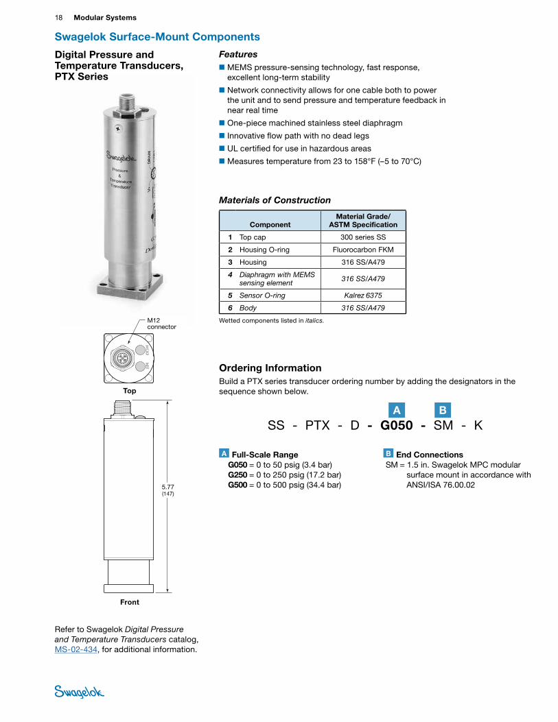
Refer to Swagelok Digital Pressure and Temperature Transducers catalog, MS-02-434, for additional information.
Swagelok Surface-Mount Components
M12 connector
5.77 (147)
Front
Top
Digital Pressure and Temperature Transducers, PTX Series
Ordering InformationBuild a PTX series transducer ordering number by adding the designators in the sequence shown below.
Materials of Construction
ComponentMaterial Grade/
ASTM Specification
1 Top cap 300 series SS
2 Housing O-ring Fluorocarbon FKM
3 Housing 316 SS/A479
4 Diaphragm with MEMS sensing element 316 SS/A479
5 Sensor O-ring Kalrez 6375
6 Body 316 SS/A479
Wetted components listed in italics.
Features■MEMS pressure-sensing technology, fast response,
excellent long-term stability
■Network connectivity allows for one cable both to power the unit and to send pressure and temperature feedback in near real time
■One-piece machined stainless steel diaphragm
■Innovative flow path with no dead legs
■UL certified for use in hazardous areas
■Measures temperature from 23 to 158°F (–5 to 70°C)
A Full-Scale Range G050 = 0 to 50 psig (3.4 bar) G250 = 0 to 250 psig (17.2 bar) G500 = 0 to 500 psig (34.4 bar)
SS - PTX - D - G050 - SM - K
B End Connections SM = 1.5 in. Swagelok MPC modular
surface mount in accordance with ANSI/ISA 76.00.02
A B
Modular Platform Components (MPC) 19 PIPE, W
ELD, VCR, VCO FITTINGS
STANDARD TUBING
MPC
COMPONENTS
HOSE / FLEXIBLE TUBING
BELLOWS,
DIAPHRAGM
VALVES
BALL & PLUG VALVES
CHECK & RELIEF VALVES
NEEDLE & M
ETERING VALVES
REGULATORS & FILTERS
INSTRUMENT
MANIFOLD
SYSTEMS
MEASUREM
ENT DEVICES
REFERENCESM
EDIUM- HIGH-
PRESSURETUBE
FITTINGS
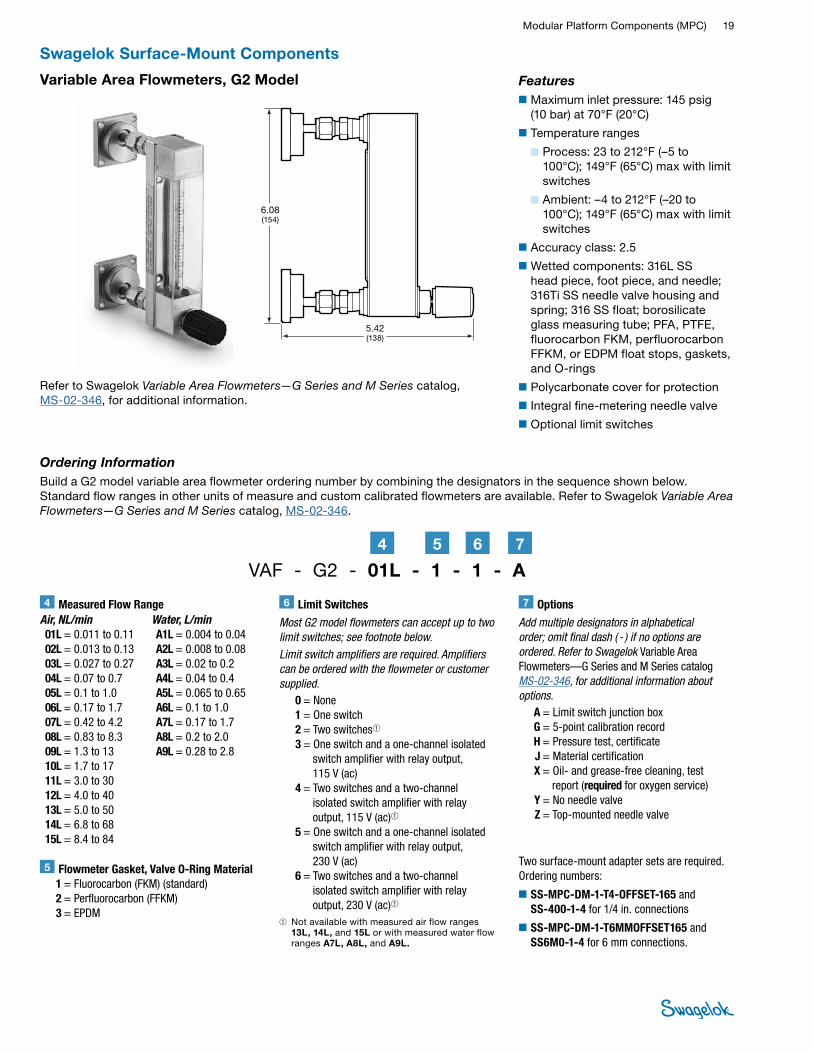
Refer to Swagelok Variable Area Flowmeters—G Series and M Series catalog, MS-02-346, for additional information.
Swagelok Surface-Mount Components
Variable Area Flowmeters, G2 Model Features■Maximum inlet pressure: 145 psig
(10 bar) at 70°F (20°C)
■Temperature ranges
■ Process: 23 to 212°F (–5 to 100°C); 149°F (65°C) max with limit switches
■ Ambient: –4 to 212°F (–20 to 100°C); 149°F (65°C) max with limit switches
■Accuracy class: 2.5
■Wetted components: 316L SS head piece, foot piece, and needle; 316Ti SS needle valve housing and spring; 316 SS float; borosilicate glass measuring tube; PFA, PTFE, fluorocarbon FKM, perfluorocarbon FFKM, or EDPM float stops, gaskets, and O-rings
■Polycarbonate cover for protection
■Integral fine-metering needle valve
■Optional limit switches
6.08 (154)
5.42 (138)
Ordering InformationBuild a G2 model variable area flowmeter ordering number by combining the designators in the sequence shown below. Standard flow ranges in other units of measure and custom calibrated flowmeters are available. Refer to Swagelok Variable Area Flowmeters—G Series and M Series catalog, MS-02-346.
Two surface-mount adapter sets are required. Ordering numbers:
■SS-MPC-DM-1-T4-OFFSET-165 and SS-400-1-4 for 1/4 in. connections
■SS-MPC-DM-1-T6MMOFFSET165 and SS6M0-1-4 for 6 mm connections.
VAF - G2 - 01L - 1 - 1 - A5 74 6
Air, NL/min 01L = 0.011 to 0.11 02L = 0.013 to 0.13 03L = 0.027 to 0.27 04L = 0.07 to 0.7 05L = 0.1 to 1.0 06L = 0.17 to 1.7 07L = 0.42 to 4.2 08L = 0.83 to 8.3 09L = 1.3 to 13 10L = 1.7 to 17 11L = 3.0 to 30 12L = 4.0 to 40 13L = 5.0 to 50 14L = 6.8 to 68 15L = 8.4 to 84
Water, L/min A1L = 0.004 to 0.04 A2L = 0.008 to 0.08 A3L = 0.02 to 0.2 A4L = 0.04 to 0.4 A5L = 0.065 to 0.65 A6L = 0.1 to 1.0 A7L = 0.17 to 1.7 A8L = 0.2 to 2.0 A9L = 0.28 to 2.8
4 Measured Flow Range
5 Flowmeter Gasket, Valve O-Ring Material 1 = Fluorocarbon (FKM) (standard) 2 = Perfluorocarbon (FFKM) 3 = EPDM
6 Limit Switches
Most G2 model flowmeters can accept up to two limit switches; see footnote below. Limit switch amplifiers are required. Amplifiers can be ordered with the flowmeter or customer supplied. 0 = None 1 = One switch 2 = Two switches➀ 3 = One switch and a one-channel isolated
switch amplifier with relay output, 115 V (ac)
4 = Two switches and a two-channel isolated switch amplifier with relay output, 115 V (ac)➀
5 = One switch and a one-channel isolated switch amplifier with relay output, 230 V (ac)
6 = Two switches and a two-channel isolated switch amplifier with relay output, 230 V (ac)➀
➀ Not available with measured air flow ranges 13L, 14L, and 15L or with measured water flow ranges A7L, A8L, and A9L.
7 Options
Add multiple designators in alphabetical order; omit final dash ( - ) if no options are ordered. Refer to Swagelok Variable Area Flowmeters—G Series and M Series catalog MS-02-346, for additional information about options. A = Limit switch junction box G = 5-point calibration record H = Pressure test, certificate J = Material certification X = Oil- and grease-free cleaning, test
report (required for oxygen service) Y = No needle valve Z = Top-mounted needle valve
20 Modular SystemsTU
BE
FITTI
NGS
PIPE
, WEL
D,
VCR,
VCO
FIT
TING
S
STAN
DARD
TU
BING
MPC
COM
PONE
NTS
HOSE
/ FL
EXIB
LE
TUBI
NG
BELL
OWS,
DI
APHR
AGM
VA
LVES
BALL
& P
LUG
VALV
ES
NEED
LE &
M
ETER
ING
VA
LVES
CHEC
K &
RELIE
F VA
LVES
REGU
LATO
RS
& FIL
TERS
INST
RUM
ENT
MAN
IFOLD
SY
STEM
S
MEA
SURE
MEN
T DE
VICE
SRE
FERE
NCES
MED
IUM
- HIG
H-
PRES
SURE
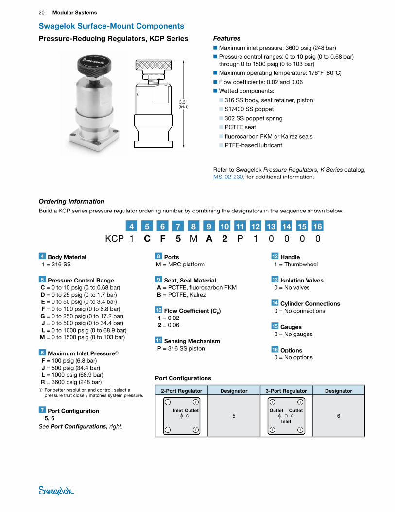
Pressure-Reducing Regulators, KCP Series
Ordering InformationBuild a KCP series pressure regulator ordering number by combining the designators in the sequence shown below.
Features■Maximum inlet pressure: 3600 psig (248 bar)
■Pressure control ranges: 0 to 10 psig (0 to 0.68 bar) through 0 to 1500 psig (0 to 103 bar)
■Maximum operating temperature: 176°F (80°C)
■Flow coefficients: 0.02 and 0.06
■Wetted components:
■ 316 SS body, seat retainer, piston
■ S17400 SS poppet
■ 302 SS poppet spring
■ PCTFE seat
■ fluorocarbon FKM or Kalrez seals
■ PTFE-based lubricant
Refer to Swagelok Pressure Regulators, K Series catalog, MS-02-230, for additional information.
Swagelok Surface-Mount Components
3.31 (84.1)
4 Body Material 1 = 316 SS
7 Port Configuration 5, 6See Port Configurations, right.
8 Ports M = MPC platform
9 Seat, Seal Material A = PCTFE, fluorocarbon FKM B = PCTFE, Kalrez
11 Sensing Mechanism P = 316 SS piston
12 Handle 1 = Thumbwheel
13 Isolation Valves 0 = No valves
14 Cylinder Connections 0 = No connections
15 Gauges 0 = No gauges
16 Options 0 = No options
KCP 1 C F 5 M A 2 P 1 0 0 0 0
5 Pressure Control Range C = 0 to 10 psig (0 to 0.68 bar) D = 0 to 25 psig (0 to 1.7 bar) E = 0 to 50 psig (0 to 3.4 bar) F = 0 to 100 psig (0 to 6.8 bar) G = 0 to 250 psig (0 to 17.2 bar) J = 0 to 500 psig (0 to 34.4 bar) L = 0 to 1000 psig (0 to 68.9 bar) M = 0 to 1500 psig (0 to 103 bar)
6 Maximum Inlet Pressure➀ F = 100 psig (6.8 bar) J = 500 psig (34.4 bar) L = 1000 psig (68.9 bar) R = 3600 psig (248 bar)➀ For better resolution and control, select a
pressure that closely matches system pressure.
5 74 6 8 9 10 11 12 13 14 1615
10 Flow Coefficient (Cv) 1 = 0.02 2 = 0.06
Port Configurations
2-Port Regulator Designator 3-Port Regulator Designator
5 6Inlet Outlet Outlet Outlet
Inlet

Modular Platform Components (MPC) 21 PIPE, W
ELD, VCR, VCO FITTINGS
STANDARD TUBING
MPC
COMPONENTS
HOSE / FLEXIBLE TUBING
BELLOWS,
DIAPHRAGM
VALVES
BALL & PLUG VALVES
CHECK & RELIEF VALVES
NEEDLE & M
ETERING VALVES
REGULATORS & FILTERS
INSTRUMENT
MANIFOLD
SYSTEMS
MEASUREM
ENT DEVICES
REFERENCESM
EDIUM- HIGH-
PRESSURETUBE
FITTINGSBack-Pressure Regulators, KCB Series
Ordering InformationBuild a KCB series back-pressure regulator ordering number by combining the designators in the sequence shown below.
Features■Maximum inlet pressure: equal to pressure control range
■Pressure control ranges: 0 to 10 psig (0 to 0.68 bar) through 0 to 250 psig (17.2 bar)
■Maximum operating temperature: 176°F (80°C)
■Flow coefficient: 0.10
■Wetted components:
■ 316 SS body, seat retainer, piston
■ fluorocarbon FKM or Kalrez seat and piston seal
■ PCTFE retainer seal
■ PTFE-based lubricant
Refer to Swagelok Pressure Regulators, K Series catalog, MS-02-230, for additional information.
Swagelok Surface-Mount Components
3.31 (84.1)
4 Body Material 1 = 316 SS
7 Port Configuration 7, 8See Port Configurations, right.
8 Ports M = MPC platform
9 Seat, Seal Material A = Fluorocarbon FKM, PCTFE B = Kalrez, PCTFE
11 Sensing Mechanism P = 316 SS piston
12 Handle 1 = Thumbwheel
13 Valves 0 = No valves
14 Cylinder Connections 0 = No connections
15 Gauges 0 = No gauges
16 Options 0 = No options
5 Pressure Control Range C = 0 to 10 psig (0 to 0.68 bar) D = 0 to 25 psig (0 to 1.7 bar) E = 0 to 50 psig (0 to 3.4 bar) F = 0 to 100 psig (0 to 6.8 bar) G = 0 to 250 psig (0 to 17.2 bar)
6 Maximum Inlet Pressure 0 = Not applicable (equal to pressure
control range)
10 Flow Coefficient (Cv) 4 = 0.10
KCB 1 F 0 7 M A 4 P 1 0 0 0 05 74 6 8 9 10 11 12 13 14 1615
Port Configurations
2-Port Regulator Designator 3-Port Regulator Designator
7 8Outlet Inlet Inlet Inlet
Outlet

22 Modular SystemsTU
BE
FITTI
NGS
PIPE
, WEL
D,
VCR,
VCO
FIT
TING
S
STAN
DARD
TU
BING
MPC
COM
PONE
NTS
HOSE
/ FL
EXIB
LE
TUBI
NG
BELL
OWS,
DI
APHR
AGM
VA
LVES
BALL
& P
LUG
VALV
ES
NEED
LE &
M
ETER
ING
VA
LVES
CHEC
K &
RELIE
F VA
LVES
REGU
LATO
RS
& FIL
TERS
INST
RUM
ENT
MAN
IFOLD
SY
STEM
S
MEA
SURE
MEN
T DE
VICE
SRE
FERE
NCES
MED
IUM
- HIG
H-
PRES
SURE
Tee-Type Filters, TF Series
Refer to Swagelok Filters—FW, F, and TF Series catalog, MS-01-92, for additional information.
FeaturesPressure-Temperature Ratings
Seal Material Fluorocarbon FKM
Temperature °F (°C)
Working Pressure psig (bar)
0 (–17) to 100 (37) 150 (65) 200 (93) 250 (121) 300 (148)
3600 (248)3320 (228)3040 (209)2786 (191)2115 (145)
■Wetted components: 316L SS body; 316 SS bonnet, elements, and gasket (silver plated); 302 SS spring
■Replaceable elements in a variety of nominal pore sizes 1.73
(43.9)
Flow Data at 70°F (20°C)
Element Nominal
Pore Size µm
Inlet Pressure,➀ psig (bar) Pressure Drop, psi (bar)
5 (0.34) 10 (0.68) 15 (1.0) 10 (0.68) 50 (3.4) 100 (6.8)
Air Flow, std ft3/min (std L/min) Water Flow, U.S. gal/min (L/min)
0.5 0.13 (3.6) 0.20 (5.6) 0.26 (7.3) 0.04 (0.15) 0.10 (0.37) 0.14 (0.52)
2 0.39 (11) 0.59 (16) 0.77 (21) 0.13 (0.49) 0.30 (1.1) 0.42 (1.5)
7 0.55 (15) 0.83 (23) 1.1 (31) 0.19 (0.71) 0.42 (1.5) 0.59 (2.2)
15 0.61 (17) 0.93 (26) 1.2 (33) 0.21 (0.79) 0.47 (1.7) 0.66 (2.4)
60 0.76 (21) 1.2 (33) 1.5 (42) 0.26 (0.98) 0.58 (2.1) 0.82 (3.1)
90 0.82 (23) 1.2 (33) 1.6 (45) 0.28 (1.0) 0.62 (2.3) 0.88 (3.3) 40, 140,
230, 440
➀ Outlet is discharged to atmosphere.
Ordering Information
Element Nominal
Pore Size µm
2-Port Filter
3-Port Filter
Sintered Elements
0.5 SS-MPC-4TF-2-05 SS-MPC-4TF-3-05
2 SS-MPC-4TF-2-2 SS-MPC-4TF-3-2
7 SS-MPC-4TF-2-7 SS-MPC-4TF-3-7
15 SS-MPC-4TF-2-15 SS-MPC-4TF-3-15
60 SS-MPC-4TF-2-60 SS-MPC-4TF-3-60
90 SS-MPC-4TF-2-90 SS-MPC-4TF-3-90
Strainer Elements
40 SS-MPC-4TF-2-40 SS-MPC-4TF-3-40
140 SS-MPC-4TF-2-140 SS-MPC-4TF-3-140
230 SS-MPC-4TF-2-230 SS-MPC-4TF-3-230
440 SS-MPC-4TF-2-440 SS-MPC-4TF-3-440
Swagelok Surface-Mount Components
Modular Platform Components (MPC) 23 PIPE, W
ELD, VCR, VCO FITTINGS
STANDARD TUBING
MPC
COMPONENTS
HOSE / FLEXIBLE TUBING
BELLOWS,
DIAPHRAGM
VALVES
BALL & PLUG VALVES
CHECK & RELIEF VALVES
NEEDLE & M
ETERING VALVES
REGULATORS & FILTERS
INSTRUMENT
MANIFOLD
SYSTEMS
MEASUREM
ENT DEVICES
REFERENCESM
EDIUM- HIGH-
PRESSURETUBE
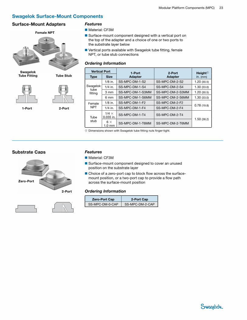
FITTINGSSurface-Mount Adapters
Features■Material: CF3M
■Surface-mount component designed to cover an unused position on the substrate layer
■Choice of a zero-port cap to block flow across the surface-mount position, or a two-port cap to provide a flow path across the surface-mount position
Features■Material: CF3M
■Surface-mount component designed with a vertical port on the top of the adapter and a choice of one or two ports to the substrate layer below
■Vertical ports available with Swagelok tube fitting, female NPT, or tube stub connections
Substrate Caps
Zero-Port
2-Port
Tube Stub Swagelok
Tube Fitting
Female NPT
➀ Dimensions shown with Swagelok tube fitting nuts finger-tight.
Ordering Information
Vertical Port 1-Port Adapter
2-Port Adapter
Height➀ in. (mm) Type Size
Swagelok tube fitting
1/8 in. SS-MPC-DM-1-S2 SS-MPC-DM-2-S2 1.20 (30.5)
1/4 in. SS-MPC-DM-1-S4 SS-MPC-DM-2-S4 1.30 (33.0)
3 mm SS-MPC-DM-1-S3MM SS-MPC-DM-2-S3MM 1.20 (30.5)
6 mm SS-MPC-DM-1-S6MM SS-MPC-DM-2-S6MM 1.30 (33.0)
Female NPT
1/8 in. SS-MPC-DM-1-F2 SS-MPC-DM-2-F2 0.78 (19.8)
1/4 in. SS-MPC-DM-1-F4 SS-MPC-DM-2-F4
Tube stub
1/4 × 0.035 in.
SS-MPC-DM-1-T4 SS-MPC-DM-2-T4 1.50 (38.2)
6 × 1.0 mm
SS-MPC-DM-1-T6MM SS-MPC-DM-2-T6MM
Ordering Information
Zero-Port Cap 2-Port Cap
SS-MPC-DM-0-CAP SS-MPC-DM-2-CAP
Swagelok Surface-Mount Components
1-Port 2-Port

24 Modular SystemsTU
BE
FITTI
NGS
PIPE
, WEL
D,
VCR,
VCO
FIT
TING
S
STAN
DARD
TU
BING
MPC
COM
PONE
NTS
HOSE
/ FL
EXIB
LE
TUBI
NG
BELL
OWS,
DI
APHR
AGM
VA
LVES
BALL
& P
LUG
VALV
ES
NEED
LE &
M
ETER
ING
VA
LVES
CHEC
K &
RELIE
F VA
LVES
REGU
LATO
RS
& FIL
TERS
INST
RUM
ENT
MAN
IFOLD
SY
STEM
S
MEA
SURE
MEN
T DE
VICE
SRE
FERE
NCES
MED
IUM
- HIG
H-
PRES
SURE
Swagelok Surface-Mount Components
Standard Industrial Sensor
Electrical Specifications
Turck Part Number
Bi 1-EG05-AP6X-V1331/S1367➀ Bi 1-EH04-AP6X-V1131/S1164➁
Connection Turck picofast® snap lock, 3-pin (PKG 3Z cable)
Output 3-wire V (dc)—transistor (PNP current-sourcing)
Voltage 10 to 30 V (dc) polarity protected—pulsed SCP
Output Function Normally open
Operating Temperature –23 to 70°C (–10 to 158°F)
Wiring Diagram
Load
BN
BU
BK
+
–
PNP
Ordering InformationTo order an electronic position sensor factory assembled, add:
■-PS for a standard industrial sensor
■-PS-IS for an intrinsically safe sensor
to a pneumatically actuated DP series, PSV series, T2A series, or SSV series surface-mount component ordering number.
Examples: SS-MPC-DP-2-C-PS SS-MPC-PSV-3-SC-PS-IS
Intrinsically Safe Sensor
Electrical Specifications
Turck Part Number Bi 1-EH04-Y1-V1130/S1164
Connection Turck picofast snap lock, 3-pin (PKG 3Z cable)
Output2-wire NAMUR-style
(IEC60947-5-6 [EN60947-5-6])
Voltage NAMUR switch amplifier required
Output Function Normally open
Operating Temperature –23 to 70°C (–10 to 158°F)
Wiring Diagram
BN
BU
+
–
NAMUR
SWITCH AMPLIFIER
Surface-mount valves with standard industrial electronic position sensors: normally closed DP series valve, left, and normally closed T2A series valve.
Electronic Position SensorsSelect surface-mount valves are available with electronic position sensors, which transmit a signal to an electrical device indicating:
■the open position of:
■ pneumatically actuated DP series low-pressure valves, normally open and normally closed
■ PSV series switching valves
■ T2A series shutoff valves, normally open and normally closed.
■the closed position of SSV series stream selector valves.
FeaturesStandard industrial and intrinsically safe sensor models are available. Both models:
■offer instant, remote confirmation of valve actuator position
■validate valve response.
The industrial model aids troubleshooting with a local LED indicator.
The intrinsically safe model is designed for use in applications where intrinsically safe ratings are required, such as hazardous environments or media.
➀ For DP and PSV series ➁ For T2 series

Modular Platform Components (MPC) 25 PIPE, W
ELD, VCR, VCO FITTINGS
STANDARD TUBING
MPC
COMPONENTS
HOSE / FLEXIBLE TUBING
BELLOWS,
DIAPHRAGM
VALVES
BALL & PLUG VALVES
CHECK & RELIEF VALVES
NEEDLE & M
ETERING VALVES
REGULATORS & FILTERS
INSTRUMENT
MANIFOLD
SYSTEMS
MEASUREM
ENT DEVICES
REFERENCESM
EDIUM- HIGH-
PRESSURETUBE
FITTINGS
Surface-Mount Accessories
Digital Valve Control Modules (VCM)The Swagelok VCM uses a sophisticated control and monitoring system to operate up to six pneumatic stream selecting valves or other discrete valves. This compact system reduces complicated cabling and minimizes overall power consumption.
Features■300 series stainless steel construction
■Network-controlled automatic valve actuation with DeviceNet™ network interface
■Indicator LEDs for pilot valve state, network status, and module status
■Threaded end connections for inlet, outlets, and exhaust; push-to-connect fittings available for 1/8 in. plastic tubing
■UL certified for use in hazardous areas
■Proximity sensor interface option to ensure proper valve actuation
Ordering InformationSelect an ordering number.
Proximity Sensor Interface Ordering Number
No interface SS-VCM-D-6-0
Terminal strip with sealed enclosure SS-VCM-D-6-2
The SS-VCM-D-6-2 model is designed to work with the MPC surface-mount components equipped with the Turck Bi 1-EG05-AP6X posiion sensor; see page 24.
Terminal Strip Proximity Sensor Interface
(shown enlarged, without sealed enclosure)
Terminal Strip Proximity Sensor
Interface With Sealed Enclosure
No Proximity Sensor Interface
Refer to Swagelok Digital Valve Control Module (VCM) catalog, MS-02-435, for additional information.

26 Modular SystemsTU
BE
FITTI
NGS
PIPE
, WEL
D,
VCR,
VCO
FIT
TING
S
STAN
DARD
TU
BING
MPC
COM
PONE
NTS
HOSE
/ FL
EXIB
LE
TUBI
NG
BELL
OWS,
DI
APHR
AGM
VA
LVES
BALL
& P
LUG
VALV
ES
NEED
LE &
M
ETER
ING
VA
LVES
CHEC
K &
RELIE
F VA
LVES
REGU
LATO
RS
& FIL
TERS
INST
RUM
ENT
MAN
IFOLD
SY
STEM
S
MEA
SURE
MEN
T DE
VICE
SRE
FERE
NCES
MED
IUM
- HIG
H-
PRES
SURE
Swagelok Substrate and Manifold Components
Substrate Flow Components
Surface-Mount Connectors
Cutaway
Description Ordering Number
Ain. (mm) Port 1 Port 2
Side
Side 6L-MPC-WS-SHSH 1.22 (31.0)
Center 6L-MPC-WS-SHLG
1.53 (38.9) Center and manifold 6L-MPC-WS-SHDT
Manifold 6L-MPC-WS-SHDE
Center
Center 6L-MPC-WS-LGLG
1.83 (46.5)
Center and manifold 6L-MPC-WS-LGDT
Manifold 6L-MPC-WS-LGDE
Center and manifold
Center and manifold 6L-MPC-WS-DTDT
Manifold 6L-MPC-WS-DTDE
Manifold Manifold 6L-MPC-WS-DEDE
APort 1 Port 2
0.42 (10.7)
A
0.52 (13.2)
1.53 (38.9)
1.51 (38.4)
Substrate Channels
Number of Surface-Mount
Positions Ordering Number
A in. (mm)
Number of Surface-Mount
Positions Ordering Number
A in. (mm)
1 A-MPC-SB-01 2.60 (66.0) 8 A-MPC-SB-08 13.3 (338)
2 A-MPC-SB-02 4.13 (105) 9 A-MPC-SB-09 14.8 (376)
3 A-MPC-SB-03 5.66 (144) 10 A-MPC-SB-10 16.4 (417)
4 A-MPC-SB-04 7.19 (183) 11 A-MPC-SB-11 17.9 (455)
5 A-MPC-SB-05 8.72 (221) 12 A-MPC-SB-12 19.4 (493)
6 A-MPC-SB-06 10.2 (259) 13 A-MPC-SB-13 21.0 (533)
7 A-MPC-SB-07 11.8 (300) 14 A-MPC-SB-14 22.5 (572)
Dimensions, in inches (millimeters), are for reference only and are subject to change.

Modular Platform Components (MPC) 27 PIPE, W
ELD, VCR, VCO FITTINGS
STANDARD TUBING
MPC
COMPONENTS
HOSE / FLEXIBLE TUBING
BELLOWS,
DIAPHRAGM
VALVES
BALL & PLUG VALVES
CHECK & RELIEF VALVES
NEEDLE & M
ETERING VALVES
REGULATORS & FILTERS
INSTRUMENT
MANIFOLD
SYSTEMS
MEASUREM
ENT DEVICES
REFERENCESM
EDIUM- HIGH-
PRESSURETUBE
FITTINGS
APort 1 Port 2
0.42 (10.7)
Jumper Tube Connectors
Number of Surface-Mount
Positions Skipped
Ordering Number
A in. (mm)
1 6L-MPC-WS-SHTB01SH➀ 2.75 (69.8)
6L-MPC-WS-SHTB01LG 3.06 (77.7)
2 6L-MPC-WS-SHTB02LG 4.59 (117)
3 6L-MPC-WS-SHTB03LG 6.12 (155)
4 6L-MPC-WS-SHTB04LG 7.65 (194)
5 6L-MPC-WS-SHTB05LG 9.18 (233)
6 6L-MPC-WS-SHTB06LG 10.7 (272)
7 6L-MPC-WS-SHTB07LG 12.2 (310)
8 6L-MPC-WS-SHTB08LG 13.8 (351)
Drop-Down Connector and Plug
Cutaway Description Ordering Number
Drop-down connector for substrate to
manifold 6L-MPC-WS-DD
Plug for manifold port with no substrate component above
6L-MPC-WS-DP
0.42 (10.7)
0.30 (7.6)
Substrate Flow Components
Substrate End Connectors
Description Ordering Number
Dimensions, in. (mm)
Port 1 Port 2 A B D
1/8 in. Swagelok tube fitting
Side 6L-MPC-WS-SHS2 1.65 (41.9)
1.50 (38.1)
0.50 (12.7)
Center 6L-MPC-WS-LGS2
1.96 (49.8)
1.81 (46.0)
Center and manifold 6L-MPC-WS-DTS2
Manifold 6L-MPC-WS-DES2
1/4 in. Swagelok tube fitting
Side 6L-MPC-WS-SHS4 1.59 (40.4)
1.44 (36.6)
0.60 (15.2)
Center 6L-MPC-WS-LGS4
1.90 (48.31)
1.75 (44.4)
Center and manifold 6L-MPC-WS-DTS4
Manifold 6L-MPC-WS-DES4
3 mm Swagelok tube fitting
Side 6L-MPC-WS-SHS3MM 1.65 (41.9)
1.50 (38.1)
0.50 (12.7)
Center 6L-MPC-WS-LGS3MM
1.96 (49.8)
1.81 (46.0)
Center and manifold 6L-MPC-WS-DTS3MM
Manifold 6L-MPC-WS-DES3MM
6 mm Swagelok tube fitting
Side 6L-MPC-WS-SHS6MM 1.59 (40.4)
1.44 (36.6)
0.60 (15.2)
Center 6L-MPC-WS-LGS6MM
1.90 (48.31)
1.75 (44.4)
Center and manifold 6L-MPC-WS-DTS6MM
Manifold 6L-MPC-WS-DES6MM
Dimensions shown with Swagelok tube fitting nuts finger-tight.
Swagelok Substrate and Manifold Components
Side
Center
Center and Manifold
Manifold
➀ Used with SSV stream selector valve outlet.
Dimensions, in inches (millimeters), are for reference only and are subject to change.
AB
Port 1
Port 2
0.42 (10.7)
D

28 Modular SystemsTU
BE
FITTI
NGS
PIPE
, WEL
D,
VCR,
VCO
FIT
TING
S
STAN
DARD
TU
BING
MPC
COM
PONE
NTS
HOSE
/ FL
EXIB
LE
TUBI
NG
BELL
OWS,
DI
APHR
AGM
VA
LVES
BALL
& P
LUG
VALV
ES
NEED
LE &
M
ETER
ING
VA
LVES
CHEC
K &
RELIE
F VA
LVES
REGU
LATO
RS
& FIL
TERS
INST
RUM
ENT
MAN
IFOLD
SY
STEM
S
MEA
SURE
MEN
T DE
VICE
SRE
FERE
NCES
MED
IUM
- HIG
H-
PRES
SURE
Elbow-to-Swagelok Tube Fitting
Number of Surface-Mount
Positions
Basic Ordering Number
A in. (mm)
1 6L-MPC-MS-ME 1.58 (40.1)
2 6L-MPC-MS-MEMT01 3.18 (80.8)
3 6L-MPC-MS-MEMT02 4.78 (121)
4 6L-MPC-MS-MEMT03 6.38 (162)
5 6L-MPC-MS-MEMT04 7.98 (203)
6 6L-MPC-MS-MEMT05 9.60 (244)
7 6L-MPC-MS-MEMT06 11.2 (284)
8 6L-MPC-MS-MEMT07 12.8 (325)
9 6L-MPC-MS-MEMT08 14.4 (366)
10 6L-MPC-MS-MEMT09 16.0 (406)
Dimensions shown with Swagelok tube fitting nuts finger-tight.
To order, add a Swagelok tube fitting size designator to a basic ordering number.
Example: 6L-MPC-MS-MES4
Swagelok Tube Fitting
Size DesignatorD
in. (mm)
1/8 in. S2 0.50 (12.7)
1/4 in. S4 0.60 (15.2)
3 mm S3MM 0.50 (12.7)
6 mm S6MM 0.60 (15.2)
ASwagelok Tube Fitting-to-Swagelok Tube Fitting
Number of Surface-Mount
Positions
Basic Ordering Number
A in. (mm)
1 6L-MPC-MS-___MT01 3.01 (76.5)
2 6L-MPC-MS-___MT02 4.61 (117)
3 6L-MPC-MS-___MT03 6.21 (158)
4 6L-MPC-MS-___MT04 7.81 (198)
5 6L-MPC-MS-___MT05 9.40 (239)
6 6L-MPC-MS-___MT06 11.0 (279)
7 6L-MPC-MS-___MT07 12.6 (320)
8 6L-MPC-MS-___MT08 14.2 (361)
9 6L-MPC-MS-___MT09 15.8 (401)
10 6L-MPC-MS-___MT10 17.4 (442)
Dimensions shown with Swagelok tube fitting nuts finger-tight.
To order, insert a Swagelok tube fitting size designator as shown and add the same designator to a basic ordering number.
Example: 6L-MPC-MS-S4MT01S4
Dimensions, in inches (millimeters), are for reference only and are subject to change.
Swagelok Substrate and Manifold Components
A1.38 (35.1) 1.60 (40.6)
0.51 (13.0)
D
D1.38 (35.1) 1.38 (35.1)
D
Manifold Flow Components
Tee Connectors
Elbow-to-Elbow
Number of Surface-Mount
Positions Ordering Number
A in. (mm)
2 6L-MPC-MS-MEME 2.00 (50.8)
3 6L-MPC-MS-MEMT01ME 3.60 (91.4)
4 6L-MPC-MS-MEMT02ME 5.20 (132)
5 6L-MPC-MS-MEMT03ME 6.80 (173)
6 6L-MPC-MS-MEMT04ME 8.40 (213)
7 6L-MPC-MS-MEMT05ME 10.0 (254)
8 6L-MPC-MS-MEMT06ME 11.6 (295)
9 6L-MPC-MS-MEMT07ME 13.2 (335)
10 6L-MPC-MS-MEMT08ME 14.8 (376)
A
0.51 (13.0)
1.60 (40.6) 1.60 (40.6)
Swagelok Tube Fitting
Size DesignatorD
in. (mm)
1/8 in. S2 0.50 (12.7)
1/4 in. S4 0.60 (15.2)
3 mm S3MM 0.50 (12.7)
6 mm S6MM 0.60 (15.2)
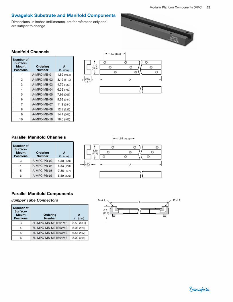
Modular Platform Components (MPC) 29 PIPE, W
ELD, VCR, VCO FITTINGS
STANDARD TUBING
MPC
COMPONENTS
HOSE / FLEXIBLE TUBING
BELLOWS,
DIAPHRAGM
VALVES
BALL & PLUG VALVES
CHECK & RELIEF VALVES
NEEDLE & M
ETERING VALVES
REGULATORS & FILTERS
INSTRUMENT
MANIFOLD
SYSTEMS
MEASUREM
ENT DEVICES
REFERENCESM
EDIUM- HIGH-
PRESSURETUBE
FITTINGS
Parallel Manifold Channels
Number of Surface-Mount
Positions Ordering Number
A in. (mm)
3 A-MPC-PB-03 4.30 (109)
4 A-MPC-PB-04 5.83 (148)
5 A-MPC-PB-05 7.36 (187)
6 A-MPC-PB-06 8.89 (226)
1.10 (27.9)
1.53 (38.9)
0.50 (12.7)
A
Parallel Manifold Components
Jumper Tube Connectors
Number of Surface-Mount
Positions Ordering Number
A in. (mm)
3 6L-MPC-MS-METB01ME 3.50 (88.9)
4 6L-MPC-MS-METB02ME 5.03 (128)
5 6L-MPC-MS-METB03ME 6.56 (167)
6 6L-MPC-MS-METB04ME 8.09 (205)
Port 2A
Port 1
0.51 (13.0)
Swagelok Substrate and Manifold Components
Manifold Channels
Number of Surface-Mount
Positions Ordering Number
A in. (mm)
1 A-MPC-MB-01 1.59 (40.4)
2 A-MPC-MB-02 3.19 (81.0)
3 A-MPC-MB-03 4.79 (122)
4 A-MPC-MB-04 6.39 (162)
5 A-MPC-MB-05 7.99 (203)
6 A-MPC-MB-06 9.59 (244)
7 A-MPC-MB-07 11.2 (284)
8 A-MPC-MB-08 12.8 (325)
9 A-MPC-MB-09 14.4 (366)
10 A-MPC-MB-10 16.0 (406)
A
1.60 (40.6)
1.10 (27.9)
0.50 (12.7)
Dimensions, in inches (millimeters), are for reference only and are subject to change.

30 Modular SystemsTU
BE
FITTI
NGS
PIPE
, WEL
D,
VCR,
VCO
FIT
TING
S
STAN
DARD
TU
BING
MPC
COM
PONE
NTS
HOSE
/ FL
EXIB
LE
TUBI
NG
BELL
OWS,
DI
APHR
AGM
VA
LVES
BALL
& P
LUG
VALV
ES
NEED
LE &
M
ETER
ING
VA
LVES
CHEC
K &
RELIE
F VA
LVES
REGU
LATO
RS
& FIL
TERS
INST
RUM
ENT
MAN
IFOLD
SY
STEM
S
MEA
SURE
MEN
T DE
VICE
SRE
FERE
NCES
MED
IUM
- HIG
H-
PRES
SURE
Mounting Blocks
Item Description Ordering Number Function Material
SWAGELOK IGC II COMPONENTS SUPPORT N-ELD-766
Support A-MPC-MH-SPRT
Bolts to the bottom of a substrate channel to provide midline
support to a channel with five or more surface-mount positions
Aluminum alloy 2024-T351
SWAGELOK IGC II COMPONENTS FOOT N-ELD-767
Foot A-MPC-MH-FOOT
Bolts to each end of the substrate channel to provide
mounting capability to the base plate
Spacer foot A-MPC-MH-SPCR Bolts two inline substrates
together to maintain standard surface-mount spacing
Assembly Hardware
Item Description Ordering Number Function Material
SWAGELOK IGC II COMPONENTS LOCKDOWN N-ELD-762
Lockdown bar SS-MPC-MH-LBAR
Holds down the substrate components at each end of the
substrate channel
300 series stainless steel SWAGELOK IGC II COMPONENTS
Hex socket CAP SCREW 10-32 x 1.00 in.
N-ELD-763-12
Hex socket cap screw, 10-32 × 0.50 in.
SS-MPC-MH-0500 (20 per bag)
Secures the substrate assembly to the manifold assembly
and secures the surface-mount component to the substrate
assembly 316 series stainless steel
Hex socket cap screw, 10-32 × 1.00 in.
SS-MPC-MH-1000 (10 per bag)
Secures the substrate assembly
to the foot
Seals
Item Description Ordering Number Function Material
O-ring
FC-75-MPC-006 (50 per bag) Seals the surface-mount
component to the substrate and manifold
Fluorocarbon FKM (75 durometer)
KZ-7075-OR-006 (quantity of 1)
Kalrez 7075 compound
Seals, Mounting Blocks, and Assembly Hardware
MS-02-185, RevO, January 2022
IntroductionSince 1947, Swagelok has designed, developed, and manufactured high-quality, general-purpose and specialty fluid system products to meet the evolving needs of global industries. Our focus is on understanding our customers’ needs, finding timely solutions, and adding value with our products and services.
We are pleased to provide this global edition of the book-bound Swagelok Product Catalog, which compiles more than 100 separate product catalogs, technical bulletins, and reference documents into one convenient, easy-to-use volume. Each product catalog is up to date at the time of printing, with its revision number shown on the last page of the individual catalog. Subsequent revisions will supersede the printed version and will be posted on the Swagelok website and in the Swagelok electronic Desktop Technical Reference (eDTR) tool.
For more information, visit your Swagelok website or contact your authorized Swagelok sales and service representative.
Safe Product SelectionWhen selecting a product, the total system design must be considered to ensure safe, trouble-free performance. Function, material compatibility, adequate ratings, proper installation, operation, and maintenance are the responsibilities of the system designer and user.
Warranty InformationSwagelok products are backed by The Swagelok Limited Life-time Warranty. For a copy, visit swagelok.com or contact your authorized Swagelok representative.
Not all trademarks listed below apply to this catalog. Swagelok, Cajon, Ferrule-Pak, Goop, Hinging-Colleting, IGC, Kenmac, Micro-Fit, Nupro, Snoop, Sno-Trik, SWAK, VCO, VCR, Ultra-Torr, Whitey—TM Swagelok Company15-7 PH—TM AK Steel Corp.AccuTrak, Beacon, Westlock—TM Tyco International ServicesAflas—TM Asahi Glass Co., Ltd.ASCO, El-O-Matic—TM EmersonAutoCAD—TM Autodesk, Inc.CSA—TM Canadian Standards AssociationCrastin, DuPont, Kalrez, Krytox, Teflon, Viton—TM E.I. duPont Nemours and CompanyDeviceNet—TM ODVADyneon, Elgiloy, TFM—TM Dyneon Elgiloy—TM Elgiloy Specialty Metals FM—TM FM GlobalGrafoil—TM GrafTech International Holdings, Inc.Honeywell, MICRO SWITCH—TM HoneywellMAC—TM MAC ValvesMicrosoft, Windows—TM Microsoft Corp.NACE—TM NACE InternationalPH 15-7 Mo, 17-7 PH—TM AK Steel Corppicofast—Hans Turck KGPillar—TM Nippon Pillar Packing Company, Ltd.Raychem—TM Tyco Electronics Corp.Sandvik, SAF 2507—TM Sandvik ABSimriz—TM Freudenberg-NOKSolidWorks—TM SolidWorks CorporationUL—Underwriters Laboratories Inc.Xylan—TM Whitford Corporation© 2022 Swagelok Company
• WARNING Do not mix/interchange Swagelok products or components not governed by industrial design standards, including Swagelok tube fitting end connections, with those of other manufacturers.
Related Documents