D.44 D Terminals, Z-Series Modular disconnect terminals Standard model and Roof-style Z-series standard ranges provide solutions for conductor cross-sections from 0.05 to 35 mm 2 . When using ATEX certified components in hazardous area ap- plications the installation instructions and the rated data for accessories in the technical appendix must be considered. width x length x height with TS 35 x 7.5 mm max. current / max. cond. cross-section A/mm 2 max. clamping range mm 2 IEC 60947-7-1 / VDE 0100-537 Technical data Rated data Rated voltage, feed-through terminal V Rated current A Rated cross-section mm 2 Rated impulse withstand voltage / Pollution severity kV/- Gauge to IEC 60947-1 / UL94 Flammability class Approvals Clamped conductors (H05V/H07V) Solid / stranded mm 2 Flexible / Flexible with wire end ferrule mm 2 Tightening torque range (clamping screw) Nm Stripping length / Blade size mm / - 2 clamped cables with same cross-section (H05V/H07V) Solid / stranded mm 2 Flexible / Flexible with wire end ferrule mm 2 Note Ordering data Version dark beige Wemid blue Wemid without disconnector, dark beige Wemid Note Accessories Cross-connection, pluggable 2-pole 3-pole 4-pole 10-pole End plate / Partition plate End plate dark beige Wemid Partition plate dark beige Wemid End bracket dark beige Screwdrivers Standard Test plug Plug dia. 2.3 mm Holder for cartridge fuse, 5 x 20mm 400 V ac/dc, without LED 10-36 V ac/dc, red LED 140-250V ac/dc, red LED Module connector (max. 250 V) reversed insertion possible without fittings with wire jumper with 1N4007 diode Disconnecting plug yellow Wemid Labelling systems (see large assortment in catalogue 7) Marking tags For detailed information on other accessories and appli- cations see “Accessories” ZTR 2.5 IEC UL CSA EN 60079-7 500 600 600 20 20 20 2.5 AWG 30… 12 AWG 30… 12 6/3 A3 / V-0 ari Rated connection 0.5…4 0.5…4 / 0.5…2.5 10 / 0.6 x 3.5 2.5 mm 2 flexible conductors with wire end ferrules are crimped with the Weidmüller PZ 6/5 crimping tool. 2.5 mm 2 Two connections 5.1 x 59.5 x 41.5 20 / 4 0.05 ... 4 Type Qty. Order No. ZTR 2.5 100 1831280000 ZTR 2.5 BL 100 8731710000 ZTR 2.5/O.TNHE 100 1831130000 Type Current [A] Qty. Order No. ZQV 2.5/2 24 60 1608860000 ZQV 2.5/3 24 60 1608870000 ZQV 2.5/4 24 60 1608880000 ZQV 2.5/10 24 20 1608940000 width [mm] ZAP/TW 1 2 50 1608740000 width [mm] ZEW 35 6 20 9540000000 SD 0.6x3.5x100 1 9008330000 PS 2.3 RT 20 0180400000 SIHA 3/G20 25 7921560000 SIHA 3/G20/LD 10-36V 25 7921560000 SIHA 3/G20/LD 140-250V 25 7921560000 BEST 50 1833100000 BEST/DRBR 50 1878570000 BEST/D 50 1878560000 TNST 50 1833090000 DEK 5 / WS 10/5 If the disconnection lever is replaced by the SIHA 3, this creates a fuse ter- minal. IEC 60947-7-1 / VDE 0100-537 ZTR 2.5/3AN IEC UL CSA EN 60079-7 500 600 600 20 20 20 2.5 AWG 30… 12 AWG 26… 12 6/3 A3 / V-0 ari Rated connection 0.5…4 0.5…4 / 0.5…2.5 10 / 0.6 x 3.5 2.5 mm 2 flexible conductors with wire end ferrules are crimped with the Weidmüller PZ 6/5 crimping tool. 2.5 mm 2 Three connections 5.1 x 79.5 x 41.5 20 / 4 0.05 ... 4 Type Qty. Order No. ZTR 2.5/3AN 100 8731720000 ZTR 2.5/3AN BL 100 8731730000 ZTR 2.5/3AN/O.TNHE 100 8728450000 Type Current [A] Qty. Order No. ZQV 2.5/2 24 60 1608860000 ZQV 2.5/3 24 60 1608870000 ZQV 2.5/4 24 60 1608880000 ZQV 2.5/10 24 20 1608940000 width [mm] ZAP/TW 3 2 50 1608800000 width [mm] ZEW 35 6 20 9540000000 SD 0.6x3.5x100 1 9008330000 PS 2.3 RT 20 0180400000 SIHA 3/G20 25 7921560000 SIHA 3/G20/LD 10-36V 25 7921560000 SIHA 3/G20/LD 140-250V 25 7921560000 BEST 50 1833100000 BEST/DRBR 50 1878570000 BEST/D 50 1878560000 TNST 50 1833090000 DEK 5 / WS 10/5 If the disconnection lever is replaced by the SIHA 3, this creates a fuse ter- minal.

Welcome message from author
This document is posted to help you gain knowledge. Please leave a comment to let me know what you think about it! Share it to your friends and learn new things together.
Transcript
D.44
D
Ter
min
als,
Z-S
erie
s
Modular disconnect terminals
Standard model and Roof-style
Z-series standard ranges provide solutions forconductor cross-sections from 0.05 to 35 mm2.
When using ATEX certified components in hazardous area ap-
plications the installation instructions and the rated data for
accessories in the technical appendix must be considered.
width x length x height with TS 35 x 7.5 mmmax. current / max. cond. cross-section A/mm2
max. clamping range mm2
IEC 60947-7-1 / VDE 0100-537Technical dataRated data
Rated voltage, feed-through terminal V
Rated current A
Rated cross-section mm2
Rated impulse withstand voltage / Pollution severity kV/-
Gauge to IEC 60947-1 / UL94 Flammability class
Approvals
Clamped conductors (H05V/H07V)
Solid / stranded mm2
Flexible / Flexible with wire end ferrule mm2
Tightening torque range (clamping screw) Nm
Stripping length / Blade size mm / -
2 clamped cables with same cross-section (H05V/H07V)
Solid / stranded mm2
Flexible / Flexible with wire end ferrule mm2
Note
Ordering dataVersion
dark beige Wemid
blue Wemid
without disconnector, dark beige Wemid
Note
AccessoriesCross-connection, pluggable
2-pole
3-pole
4-pole
10-pole
End plate / Partition plate
End plate dark beige Wemid
Partition plate dark beige Wemid
End bracket
dark beige
Screwdrivers
Standard
Test plug
Plug dia. 2.3 mm
Holder for cartridge fuse, 5 x 20mm
400 V ac/dc, without LED
10-36 V ac/dc, red LED
140-250V ac/dc, red LED
Module connector (max. 250 V)
reversed insertion possible without fittings
with wire jumper
with 1N4007 diode
Disconnecting plug
yellow Wemid
Labelling systems (see large assortment in catalogue 7)
Marking tags
For detailed information on other accessories and appli-cations see “Accessories”
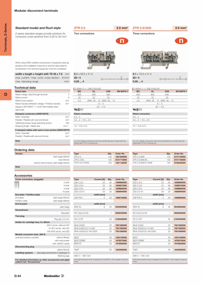
ZTR 2.5
IEC UL CSA EN 60079-7
500 600 600
20 20 20
2.5 AWG 30… 12 AWG 30… 12
6 / 3
A3 / V-0
ari
Rated connection
0.5…4
0.5…4 / 0.5…2.5
10 / 0.6 x 3.5
2.5 mm2 flexible conductors with wire end ferrules are crimped with theWeidmüller PZ 6/5 crimping tool.
2.5 mm2
Two connections
5.1 x 59.5 x 41.520 / 40.05 ... 4
Type Qty. Order No.
ZTR 2.5 100 1831280000
ZTR 2.5 BL 100 8731710000
ZTR 2.5/O.TNHE 100 1831130000
Type Current [A] Qty. Order No.
ZQV 2.5/2 24 60 1608860000
ZQV 2.5/3 24 60 1608870000
ZQV 2.5/4 24 60 1608880000
ZQV 2.5/10 24 20 1608940000
width [mm]
ZAP/TW 1 2 50 1608740000
width [mm]
ZEW 35 6 20 9540000000
SD 0.6x3.5x100 1 9008330000
PS 2.3 RT 20 0180400000
SIHA 3/G20 25 7921560000
SIHA 3/G20/LD 10-36V 25 7921560000
SIHA 3/G20/LD 140-250V 25 7921560000
BEST 50 1833100000
BEST/DRBR 50 1878570000
BEST/D 50 1878560000
TNST 50 1833090000
DEK 5 / WS 10/5
If the disconnection lever is replaced by the SIHA 3, this creates a fuse ter-minal.
IEC 60947-7-1 / VDE 0100-537
ZTR 2.5/3AN
IEC UL CSA EN 60079-7
500 600 600
20 20 20
2.5 AWG 30… 12 AWG 26… 12
6 / 3
A3 / V-0
ari
Rated connection
0.5…4
0.5…4 / 0.5…2.5
10 / 0.6 x 3.5
2.5 mm2 flexible conductors with wire end ferrules are crimped with theWeidmüller PZ 6/5 crimping tool.
2.5 mm2
Three connections
5.1 x 79.5 x 41.520 / 40.05 ... 4
Type Qty. Order No.
ZTR 2.5/3AN 100 8731720000
ZTR 2.5/3AN BL 100 8731730000
ZTR 2.5/3AN/O.TNHE 100 8728450000
Type Current [A] Qty. Order No.
ZQV 2.5/2 24 60 1608860000
ZQV 2.5/3 24 60 1608870000
ZQV 2.5/4 24 60 1608880000
ZQV 2.5/10 24 20 1608940000
width [mm]
ZAP/TW 3 2 50 1608800000
width [mm]
ZEW 35 6 20 9540000000
SD 0.6x3.5x100 1 9008330000
PS 2.3 RT 20 0180400000
SIHA 3/G20 25 7921560000
SIHA 3/G20/LD 10-36V 25 7921560000
SIHA 3/G20/LD 140-250V 25 7921560000
BEST 50 1833100000
BEST/DRBR 50 1878570000
BEST/D 50 1878560000
TNST 50 1833090000
DEK 5 / WS 10/5
If the disconnection lever is replaced by the SIHA 3, this creates a fuse ter-minal.

D.45
D
Ter
min
als,
Z-S
erie
s
Modular disconnect terminals
IEC 60947-7-1 / VDE 0100-537
ZTR 2.5/4AN
IEC UL CSA EN 60079-7
400 300 300
16 10 10
2.5 AWG 30… 12 AWG 26… 12
6 / 3
A2 / V-0
ar{#i
Rated connection
0.5…2.5
0.5…2.5 / 0.5…1.5
10 / 0.6 x 3.5
2.5 mm2 flexible conductors with wire end ferrules are crimped with theWeidmüller PZ 6/5 crimping tool.
2.5 mm2
Four connections
5.1 x 82.5 x 39.116 / 2.50.05 ... 2.5
Type Qty. Order No.
ZTR 2.5/4AN 100 7920900000
ZTR 2.5/4AN BL 100 7920930000
ZTR 2.5/4AN/O.TNHE 100 7920950000
Type Current [A] Qty. Order No.
ZQV 2.5/2 24 60 1608860000
ZQV 2.5/3 24 60 1608870000
ZQV 2.5/4 24 60 1608880000
ZQV 2.5/10 24 20 1608940000
width [mm]
ZAP/TW 3 2 50 1608800000
width [mm]
ZEW 35 6 20 9540000000
SD 0.6x3.5x100 1 9008330000
PS 2.3 RT 20 0180400000
SIHA 3/G20 25 7921560000
SIHA 3/G20/LD 10-36V 25 7921560000
SIHA 3/G20/LD 140-250V 25 7921560000
BEST 50 1833100000
BEST/DRBR 50 1878570000
BEST/D 50 1878560000
TNST 50 1833090000
DEK 5 / WS 10/5
If the disconnection lever is replaced by the SIHA 3, this creates a fuse ter-minal.
IEC 60947-7-1 / VDE 0100-537
ZDTR 2.5
IEC UL CSA EN 60079-7
400 300 300
16 10 10
2.5 AWG 26… 12 AWG 26… 12
6 / 3
A2 / V-0
ar
Rated connection
0.5…4
0.5…4 / 0.5…2.5
10 / 0.6 x 3.5
2.5 mm2 flexible conductors with wire end ferrules are crimped with theWeidmüller PZ 6/5 crimping tool.
2.5 mm2
Four connections
5.1 x 117 x 6316 / 40.05 ... 4
Type Qty. Order No.
ZDTR 2.5 20 1745400000
ZDTR 2.5 BL 20 1798330000
Type Current [A] Qty. Order No.
ZQV 2.5N/2 GE 24 60 1693800000
ZQV 2.5N/3 GE 24 60 1693810000
ZQV 2.5N/4 GE 24 60 1693820000
ZQV 2.5N/10 GE 24 20 1693880000
width [mm]
AP ZDTR2.5 1.5 20 1745420000
width [mm]
ZEW 35 6 20 9540000000
SD 0.6x3.5x100 1 9008330000
PS 2.3 RT 20 0180400000
SIHA 2/G20 25 9537600000
SIHA 2/G20 10-36V 25 9537610000
SIHA 2/G20 140-250V 25 9537640000
DEK 5
If the disconnection lever is replaced by the SIHA 2, this creates a fuse ter-minal.

D.46
D
Ter
min
als,
Z-S
erie
s
Modular disconnect terminals
Standard model and Roof-style
When using ATEX certified components in hazardous area ap-
plications the installation instructions and the rated data for
accessories in the technical appendix must be considered.
width x length x height with TS 35 x 7.5 mmmax. current / max. cond. cross-section A/mm2
max. clamping range mm2
Technical dataRated data
Rated voltage, feed-through terminal V
Rated current A
Rated cross-section mm2
Rated impulse withstand voltage / Pollution severity kV/-
Gauge to IEC 60947-1 / UL94 Flammability class
Approvals
Clamped conductors (H05V/H07V)
Solid / stranded mm2
Flexible / Flexible with wire end ferrule mm2
Tightening torque range (clamping screw) Nm
Stripping length / Blade size mm / -
2 clamped cables with same cross-section (H05V/H07V)
Solid / stranded mm2
Flexible / Flexible with wire end ferrule mm2
Note
Ordering dataVersion
dark beige Wemid
blue Wemid
without disconnector, dark beige Wemid
Note
AccessoriesCross-connection, pluggable
2-pole
3-pole
4-pole
10-pole
End plate / Partition plate
End plate dark beige Wemid
Partition plate dark beige Wemid
End bracket
dark beige
Screwdrivers
Standard
Test plug
Plug dia. 2.3 mm
Holder for cartridge fuse, 5 x 20mm
400 V ac/dc, without LED
10-36 V ac/dc, red LED
140-250V ac/dc, red LED
Module connector (max. 250 V)
reversed insertion possible without fittings
with wire jumper
with 1N4007 diode
Disconnecting plug
yellow Wemid
Labelling systems (see large assortment in catalogue 7)
Marking tags
For detailed information on other accessories and appli-cations see “Accessories”
ZDL 2.5/TR/DU
IEC UL CSA EN 60079-7
400 300 300
20 10 10
2.5 AWG 26… 12 AWG 26… 12
4
A2 / V0
Rated connection
0.5…4
0.5…4 / 0.5…2.5
8 / 0.6 x 3.5
2.5 mm2 flexible conductors with wire end ferrules are crimped with theWeidmüller PZ 6/5 crimping tool.
2.5 mm2
5.1 x 95 x 48.5/ 40.13 ... 4
Type Qty. Order No.
ZDL 2.5/TR/DU 50 1743190000
Type Current [A] Qty. Order No.
ZQV 2.5N/2 GE 24 60 1693800000
ZQV 2.5N/3 GE 24 60 1693810000
ZQV 2.5N/4 GE 24 60 1693820000
ZQV 2.5N/10 GE 24 20 1693880000
width [mm]
ZAP ZDL2.5 1.5 20 1720910000
width [mm]
ZEW 35 6 20 9540000000
SD 0.6x3.5x100 1 9008330000
PS 2.3 RT 20 0180400000
SIHA 3/G20 25 7921560000
SIHA 3/G20/LD 10-36V 25 7921560000
SIHA 3/G20/LD 140-250V 25 7921560000
BEST 50 1833100000
BEST/DRBR 50 1878570000
BEST/D 50 1878560000
TNST 50 1833090000
DEK 5
ZDL 2.5/TR/DU/PE
IEC UL CSA EN 60079-7
400 300 300
20 10 10
2.5 AWG 26… 12 AWG 26… 12
4
A2 / V0
Rated connection
0.5…4
0.5…4 / 0.5…2.5
8 / 0.6 x 3.5
2.5 mm2 flexible conductors with wire end ferrules are crimped with theWeidmüller PZ 6/5 crimping tool.
2.5 mm2
5.1 x 95 x 48.5/ 40.13 ... 4 PE
Type Qty. Order No.
ZDL 2.5/TR/DU/PE 50 1743180000
Type Current [A] Qty. Order No.
ZQV 2.5N/2 GE 24 60 1693800000
ZQV 2.5N/3 GE 24 60 1693810000
ZQV 2.5N/4 GE 24 60 1693820000
ZQV 2.5N/10 GE 24 20 1693880000
width [mm]
ZAP ZDL2.5 1.5 20 1720910000
width [mm]
ZEW 35 6 20 9540000000
SD 0.6x3.5x100 1 9008330000
PS 2.3 RT 20 0180400000
SIHA 3/G20 25 7921560000
SIHA 3/G20/LD 10-36V 25 7921560000
SIHA 3/G20/LD 140-250V 25 7921560000
BEST 50 1833100000
BEST/DRBR 50 1878570000
BEST/D 50 1878560000
TNST 50 1833090000
DEK 5

D.47
D
Ter
min
als,
Z-S
erie
s
Modular disconnect terminals
IEC 60947-7-1 / VDE 0100-537
ZTR 2.5-2
IEC UL CSA EN 60079-7
400 300 300
10 10 10
2.5 AWG 26… 12 AWG 26… 12
6 / 3
A2 / V-0
ar#i
Rated connection
0.5…2.5
0.5…2.5 / 0.5…1.5
10 / 0.6 x 3.5
2.5 mm2 flexible conductors with wire end ferrules are crimped with theWeidmüller PZ 6/5 crimping tool.
2.5 mm2
Two connections
5.1 x 50.5 x 4421 / 2.50.13 ... 2.5
Type Qty. Order No.
ZTR 2.5-2 100 1779010000
ZTR 2.5-2 BL 100 1779120000
ZTR 2.5-2/O.TNHE 100 1779020000
Type Current [A] Qty. Order No.
ZQV 2.5/2 24 60 1608860000
ZQV 2.5/3 24 60 1608870000
ZQV 2.5/4 24 60 1608880000
ZQV 2.5/10 24 20 1608940000
width [mm]
ZAP/TW7 2.5 50 1706110000
width [mm]
ZEW 35 6 20 9540000000
SD 0.6x3.5x100 1 9008330000
SIHA 3/G20 25 7921560000
SIHA 3/G20/LD 10-36V 25 7921560000
SIHA 3/G20/LD 140-250V 25 7921560000
BEST 50 1833100000
BEST/DRBR 50 1878570000
BEST/D 50 1878560000
TNST 50 1833090000
DEK 5 / WS 14/5
If the disconnection lever is replaced by the SIHA 2, this creates a fuse ter-minal.

D.48
D
Ter
min
als,
Z-S
erie
s
Fuse terminals
Z-series standard ranges provide solutions forconductor cross-sections from 0.05 to 35 mm2.
When using ATEX certified components in hazardous area ap-
plications the installation instructions and the rated data for
accessories in the technical appendix must be considered.
width x length x height with TS 35 x 7.5 mmmax. current / max. cond. cross-section A/mm2
max. clamping range mm2
IEC 60947-7-3 / VDE 0611-6Technical dataRated data
Rated voltage, adjacent terminal V
Rated current A
Rated cross-section mm2
Rated impulse withstand voltage / Pollution severity kV/-
Gauge to IEC 60947-1 / UL94 Flammability class
Approvals
Clamped conductors (H05V/H07V)
Solid / stranded mm2
Flexible / Flexible with wire end ferrule mm2
Tightening torque range (clamping screw) Nm
Stripping length / Blade size mm / -
2 clamped cables with same cross-section (H05V/H07V)
Solid / stranded mm2
Flexible / Flexible with wire end ferrule mm2
Note
Ordering dataVersion
dark beige Wemid 400 V ac/dc, without LED
10-36 V ac/dc, with LED
30-70V ac/dc, with LED
60-150 V ac/dc, with LED
140-250V ac/dc, with LED
Note
AccessoriesCross-connection, pluggable
2-pole
3-pole
4-pole
10-pole
End plate / Partition plate (after last terminal)
End plate, Wemid
Partition plate, Wemid
Screwdrivers
Standard
Cartridge fuse, 5 x 20mm (IEC 60127-2)
Rated voltage 250 V 0.25 A quick-blow
Rated breaking capacity 1500 A 0.5 A quick-blow
(at 250V / 50Hz / cos j = 0.7) 1 A quick-blow
2 A quick-blow
G25 with indicator / imperial fuse
G25 (DIN 41 576 / 250 V) 0.5 A medium time-lag / 2 A
Rated voltage 250 V 1 A medium time-lag / 3 A
Imperial fuse, 1/4 x 1 1/4 2 A quick-blow / 5 A
Rated voltage 440 V 4 A quick-blow /10 A
Labelling systems (see large assortment in catalogue 7)
Marking tags
For detailed information on other accessories and appli-cations see “Accessories”
ZSI 2.5
IEC UL CSA EN 60079-7
500 600 600
6.3 10 15
2.5 AWG 26… 12 AWG 26… 12
6 / 3
A3 / V-0
ar#;~i?
Rated connection
0.5…4
0.5…4 / 0.5…2.5
10 / 0.6 x 3.5
Max. power loss (1.6 W) at the cartridge fuse limits the rated current.
2.5 mm2
For metric fuses 5 x 20
7.9 x 79.5 x 746.3 / 40.13 ... 4
Type Qty. Order No.
ZSI 2.5 50 1616400000
ZSI 2.5/LD 28AC 50 1616440000
ZSI 2.5/LD 60AC 50 1616430000
ZSI 2.5/LD 120AC 50 1616420000
ZSI 2.5/LD 250AC 50 1616410000
For fuse cartridge holders the rated voltage is 250 V and the rated impulsewithstand voltage 4 kV.
Type Current [A] Qty. Order No.
ZQV 6/2 GE 41 A 60 1627850000
ZQV 6/3 GE 41 A 60 1627860000
ZQV 6/4 GE 41 A 60 1627870000
width [mm]
ZAP/TW 3 2 50 1608800000
SD 0.6x3.5x100 1 9008330000
G 20/0.25A/F 10 0430500000
G 20/0.5A/F 10 0430600000
G 20/1A/F 10 0430700000
G 20/2A/F 10 0430900000
DEK 5 / WS 10/5
Status indication via bidirectional LED. End plate for lever: ZAP TNHE/ZSI:1610840000
IEC 60947-7-3 / VDE 0611-6
ZSI 2.5/5x25
IEC UL CSA EN 60079-7
500 600 600
6.3 10 15
2.5 AWG 26… 12 AWG 26… 12
6 / 3
A3 / V-0
ar#
Rated connection
0.5…4
0.5…4 / 0.5…2.5
10 / 0.6 x 3.5
Max. power loss (1.6 W) at the cartridge fuse limits the rated current.
2.5 mm2
For metric fuses 5 x 25
7.9 x 79.5 x 746.3 / 40.13 ... 4
Type Qty. Order No.
ZSI 2.5/5X25 50 1730900000
For fuse cartridge holders the rated voltage is 250 V and the rated impulsewithstand voltage 4 kV.
Type Current [A] Qty. Order No.
ZQV 6/2 GE 41 A 60 1627850000
ZQV 6/3 GE 41 A 60 1627860000
ZQV 6/4 GE 41 A 60 1627870000
width [mm]
ZAP/TW 3 2 50 1608800000
SD 0.6x3.5x100 1 9008330000
G 25/0.5A/M WS 10 0510300000
G 25/1A/M RT 10 0265800000
G 25/2A/F BL 10 0192700000
G 25/4A/F BR 10 0192800000
DEK 5 / WS 10/5
End plate for fuse lever: ZAP TNHE/ZSI: 1610840000

D.49
D
Ter
min
als,
Z-S
erie
s
Fuse terminals
IEC 60947-7-3 / VDE 0611-6
ZSI 2.5/2
IEC UL CSA EN 60079-7
500 600 600
12 16 15
2.5 AWG 26… 12 AWG 26… 12
6 / 3
A3 / V-0
ar#;~i?
Rated connection
0.5…4
0.5…4 / 0.5…2.5
10 / 0.6 x 3.5
Max. power loss (1.6 W) at the cartridge fuse limits the rated current.
2.5 mm2
For imperial fuses
7.9 x 79.5 x 7412 / 40.13 ... 4
Type Qty. Order No.
ZSI 2.5/2 500AC 10 1616460000
ZSI 2.5/2/LD 28AC 10 1616470000
ZSI 2.5/2/LD 60AC 10 1616480000
ZSI 2.5/2/LD 120AC 10 1616490000
ZSI 2.5/2/LD 250AC 10 1616500000
For fuse cartridge holders the rated voltage is 250 V and the rated impulsewithstand voltage 4 kV.
Type Current [A] Qty. Order No.
ZQS 2.5/2 20 1633200000
ZQS 2.5/3 10 A 20 1633210000
ZQS 2.5/4 10 A 20 1633220000
width [mm]
SD 0.6x3.5x100 1 9008330000
GZ 10.0A 10 0293900000
DEK 5 / WS 10/5
Status indication via bidirectional LED. Use imperial cartridge fuses.
IEC 60947-7-3 / VDE 0611-6
ZDL 2.5/SI/DU
IEC UL CSA EN 60079-7
400 300 300
6.3 10 10
2.5 AWG 26… 12 AWG 26… 12
6 / 3
A3 / V-0
ar
Rated connection
0.5…4
0.5…4 / 0.5…2.5
10 / 0.6 x 3.5
Max. power loss (1.6 W) at the cartridge fuse limits the rated current.
2.5 mm2
For metric fuses 5 x 20
5.1 x 95 x 986.3 / 40.13 ... 4
Type Qty. Order No.
ZDL 2.5/SI/DU 25 1763180000
ZDL 2.5/SI/DU LD 36V 25 1763230000
ZDL 2.5/SI/DU LD 70V 25 1763240000
ZDL 2.5/SI/DU LD 150V 25 1763250000
ZDL 2.5/SI/DU LD 250V 25 1763260000
For fuse cartridge holders the rated voltage is 250 V and the rated impulsewithstand voltage 4 kV.
Type Current [A] Qty. Order No.
width [mm]
ZAP ZDL2.5 1.5 20 1720910000
SD 0.6x3.5x100 1 9008330000
G 20/0.25A/F 10 0430500000
G 20/0.5A/F 10 0430600000
G 20/1A/F 10 0430700000
G 20/2A/F 10 0430900000
DEK 5
Status indication via bidirectional LED. It is not possible to use cross-con-nections on the upper level.
IEC 60947-7-3 / VDE 0611-6
ZDL 2.5/SI/DU/PE
IEC UL CSA EN 60079-7
400
6.3
2.5
6 / 3
A3 / V-0
ar
Rated connection
0.5…4
0.5…4 / 0.5…2.5
10 / 0.6 x 3.5
Max. power loss (1.6 W) at the cartridge fuse limits the rated current.
2.5 mm2
For metric fuses 5 x 20
5.1 x 95 x 986.3 / 40.13 ... 4
PE
L
Type Qty. Order No.
ZDL 2.5/SI/DU/PE 25 1763170000
ZDL 2.5/SI/DU/PE LD 36V 25 1763190000
ZDL 2.5/SI/DU/PE LD 70V 25 1763200000
ZDL 2.5/SI/DU/PE LD150V 25 1763210000
ZDL 2.5/SI/DU/PE LD250V 25 1763220000
For fuse cartridge holders the rated voltage is 250 V and the rated impulsewithstand voltage 4 kV.
Type Current [A] Qty. Order No.
width [mm]
ZAP ZDL2.5 1.5 20 1720910000
SD 0.6x3.5x100 1 9008330000
G 20/0.25A/F 10 0430500000
G 20/0.5A/F 10 0430600000
G 20/1A/F 10 0430700000
G 20/2A/F 10 0430900000
DEK 5
Status indication via bidirectional LED. It is not possible to use cross-con-nections on the upper level.

D.50
D
Ter
min
als,
Z-S
erie
s
Fuse terminals
Z-series standard ranges provide solutions forconductor cross-sections from 0.05 to 35 mm2.
When using ATEX certified components in hazardous area ap-
plications the installation instructions and the rated data for
accessories in the technical appendix must be considered.
width x length x height with TS 35 x 7.5 mmmax. current / max. cond. cross-section A/mm2
max. clamping range mm2
IEC 60947-7-3 / VDE 0611-6Technical dataRated data
Rated voltage, adjacent terminal V
Rated current A
Rated cross-section mm2
Rated impulse withstand voltage / Pollution severity kV/-
Gauge to IEC 60947-1 / UL94 Flammability class
Approvals
Clamped conductors (H05V/H07V)
Solid / stranded mm2
Flexible / Flexible with wire end ferrule mm2
Tightening torque range (clamping screw) Nm
Stripping length / Blade size mm / -
2 clamped cables with same cross-section (H05V/H07V)
Solid / stranded mm2
Flexible / Flexible with wire end ferrule mm2
Note
Ordering dataVersion
dark beige Wemid 400 V ac/dc, without LED
10-36 V ac/dc, with LED
30-70V ac/dc, with LED
60-150 V ac/dc, with LED
140-250V ac/dc, with LED
Note
AccessoriesCross-connection, pluggable
2-pole
3-pole
4-pole
10-pole
End plate / Partition plate (after last terminal)
End plate, Wemid
Partition plate, Wemid
Screwdrivers
Standard
Cartridge fuse, 5 x 20mm (IEC 60127-2)
Rated voltage 250 V 0.25 A quick-blow
Rated breaking capacity 1500 A 0.5 A quick-blow
(at 250V / 50Hz / cos j = 0.7) 1 A quick-blow
2 A quick-blow
G25 with indicator / imperial fuse
G25 (DIN 41 576 / 250 V) 0.5 A medium time-lag / 2 A
Rated voltage 250 V 1 A medium time-lag / 3 A
Imperial fuse, 1/4 x 1 1/4 2 A quick-blow / 5 A
Rated voltage 440 V 4 A quick-blow /10 A
Labelling systems (see large assortment in catalogue 7)
Marking tags
For detailed information on other accessories and appli-cations see “Accessories”
ZSI 2.5 2x2 AN
IEC UL CSA EN 60079-7
500 300 300
10 10 10
2.5 AWG 26… 12 AWG 26… 12
4 / 3
A3 / V-0
ar{#u
Rated connection
0.5…4 0.5…4
0.5…4 / 0.5…2.5 0.5…4 / 0.5…2.5
10 / 0.6 x 3.5 10 / 0.6 x 3.5
The rated voltage of the fuse may not be exceeded; to UL & CSA 600 V / 5 A
2.5 mm2
For metric fuses 5 x 20 / 5 x 25
12.2 x 65 x 5510 / 40.18 ... 4
Type Qty. Order No.
ZSI 2.5-2/2X2AN/G20 20 1826050000
ZSI 2.5-2/2X2AN/G20/LD1 20 1867440000
ZSI 2.5-2/2X2AN/G20/LD2 20 1867430000
ZSI 2.5-2/2X2AN/G20/LD3 20 1867420000
ZSI 2.5-2/2X2AN/G20/LD4 20 1879730000
G 20 = G-fuse cartridge 5 x 20 / G 25 = G-fuse cartridge 5 x 25G25 LED types on request
Type Current [A] Qty. Order No.
ZQV 6/2 GE 41 A 60 1627850000
width [mm]
ZAP ZDU6-2 SW 2.5 50 1814710000
SD 0.6x3.5x100 1 9008330000
G 20/0.25A/F 10 0430500000
G 20/0.5A/F 10 0430600000
G 20/1A/F 10 0430700000
G 20/2A/F 10 0430900000
G 25/0.5A/M WS 10 0510300000
G 25/1A/M RT 10 0265800000
G 25/2A/F BL 10 0192700000
G 25/4A/F BR 10 0192800000
DEK 5 / WS 10/5
Status indication via neon lamp.
IEC 60947-7-3 / VDE 0611-6
ZSI 6-2
IEC UL CSA EN 60079-7
500 300 300
10 10 10
6 AWG 26… 8 AWG 26… 8
4 / 3
A3 / V-0
r{#u
Rated connection
0.5…4 0.5…10
0.5…4 / 0.5…2.5 0.5…10 / 0.5…6
10 / 0.6 x 3.5 10 / 0.6 x 3.5
The rated voltage of the fuse may not be exceeded; to UL 600 V / 5 A A 3 clamping point AWG 26-12, A 5 clamping point AWG 20-8
6 mm2
For metric fuses 5 x 20 / 5 x 25
12.2 x 65 x 5510 / 40.13 ... 4
Type Qty. Order No.
ZSI 6-2 2X2.5/G20 20 1820930000
ZSI 6-2 2X2.5/G20/LD1 20 1867500000
ZSI 6-2 2X2.5/G20/LD2 20 1867490000
ZSI 6-2 2X2.5/G20/LD3 20 1867480000
ZSI 6-2 2X2.5/G20/LD4 20 1879750000
G 20 = G-fuse cartridge 5 x 20 / G 25 = G-fuse cartridge 5 x 25 G25 LEDtypes on request
Type Current [A] Qty. Order No.
ZQV 4/2 GE 32 A 60 1608950000
width [mm]
ZAP ZDU6-2 SW 2.5 50 1814710000
SD 0.8x4.0x100 1 9008340000
G 20/0.25A/F 10 0430500000
G 20/0.5A/F 10 0430600000
G 20/1A/F 10 0430700000
G 20/2A/F 10 0430900000
G 25/0.5A/M WS 10 0510300000
G 25/1A/M RT 10 0265800000
G 25/2A/F BL 10 0192700000
G 25/4A/F BR 10 0192800000
DEK 5 / WS 10/5
Status indication via neon lamp.

D.51
D
Ter
min
als,
Z-S
erie
s
Fuse terminals
IEC 60947-7-3 / DIN 72581-3
ZSI 6-2/FC
IEC UL CSA EN 60079-7
250 300 300
30 30 25
6 AWG 22… 10 AWG 22… 10
6 / 3
A5 / V-0
r{#u
Rated connection
0.5…10
0.5…10 / 0.5…6
10 / 4.0 x 0.8
If large conductor cross-sections are used, the thermal power loss of thefuses is better dissipated.
6 mm2
For car fuses
8.1 x 70 x 54.530 / 100.33 ... 10
Type Qty. Order No.
ZSI 6-2/FC 25 1814690000
ZSI 6-2/FC LD 25 1814700000
Continuous current at fuse max. 80% IN For the cartridge fuse holder therated voltage is 250 V, and the rated impulse withstand voltage 4 kV.
Type Current [A] Qty. Order No.
ZQV 6/2 GE 41 A 60 1627850000
ZQV 6/3 GE 41 A 60 1627860000
ZQV 6/4 GE 41 A 60 1627870000
width [mm]
ZAP ZDU6-2 SW 2.5 50 1814710000
SD 0.8x4.0x100 1 9008340000
DEK 6 / WS 12/6
Status indication via bidirectional LED. Use Pudenz fuses. For ordering da-ta for cartridge fuses, see page D.141.
D.52
D
Ter
min
als,
Z-S
erie
s
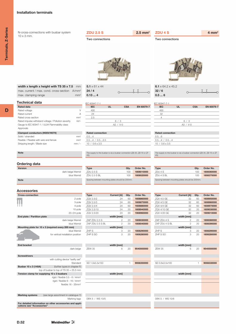
Installation terminals
N-cross-connections with busbar system 10 x 3 mm.
width x length x height with TS 35 x 7.5 mmmax. current / max. cond. cross-section A/mm2
max. clamping range mm2
IEC 60947-7-1Technical dataRated data
Rated voltage V
Rated current A
Rated cross-section mm2
Rated impulse withstand voltage / Pollution severity kV/-
Gauge to IEC 60947-1 / UL94 Flammability class
Approvals
Clamped conductors (H05V/H07V)
Solid / stranded mm2
Flexible / Flexible with wire end ferrule mm2
Stripping length / Blade size mm / -
Note
Ordering dataVersion
dark beige Wemid
blue Wemid
Note
AccessoriesCross-connection
2-pole
3-pole
4-pole
10-pole
20-/24-pole
End plate / Partition plate
dark beige Wemid
blue Wemid
Mounting plate for 10 x 3 (required every 200 mm)
blue Wemid
for vertical installation position
End bracket
dark beige
Screwdrivers
with cutting device “swifty set”
Standard
Busbar 10 x 3 (140A) (further types in chapter F)
top of busbar to top of TS 35 = 25.5 mm
Tension clamp for supplying 10 x 3 busbars
rigid / flexible 0.5 - 6 / 4mm2
rigid / flexible 6 - 16 / 4mm2
flexible 16 - 35mm2
Marking systems (see large assortment in catalogue 7)
Marking tags
For detailed information on other accessories and appli-cations see “Accessories”
ZDU 2.5 S
IEC UL CSA EN 60079-7
400
24
2.5
6 / 3
A2 / V-0
Rated connection
0.5…4
0.5…4 / 0.5…2.5
10 / 0.6 x 3.5
The supply to the busbar is via a busbar connection (ZB 35, ZB 16 or ZF4S).
2.5 mm2
Two connections
5.1 x 61 x 4424 / 40.13 ... 4
Type Qty. Order No.
ZDU 2.5 S 100 1808010000
ZDU 2.5 S BL 100 1808020000
Spacing between mounting plates should be 200mm.
Type Current [A] Qty. Order No.
ZQV 2.5/2 24 60 1608860000
ZQV 2.5/3 24 60 1608870000
ZQV 2.5/4 24 60 1608880000
ZQV 2.5/10 24 20 1608940000
ZQV 2.5/20 24 20 1908960000
width [mm]
ZAP ZDU 2.5 S 2 20 1808030000
ZAP ZDU 2.5 S BL 2 20 1808040000
width [mm]
ZHP S 3 20 1808290000
ZHP S SO 3 20 1808280000
width [mm]
ZEW 35 6 20 9540000000
SD 1.0x5.5x150 1 9008350000
width [mm]
DEK 5 / WS 10/5
IEC 60947-7-1
ZDU 4 S
IEC UL CSA EN 60079-7
400
32
4
6 / 3
A3 / V-0
Rated connection
0.5…6
0.5…4 / 0.5…4
10 / 0.6 x 3.5
The supply to the busbar is via a busbar connection (ZB 35, ZB 16 or ZF4S).
4 mm2
Two connections
6.1 x 64.2 x 45.232 / 60.5 ... 6
Type Qty. Order No.
ZDU 4 S 100 1808360000
ZDU 4 S BL 100 1808370000
Spacing between mounting plates should be 200mm.
Type Current [A] Qty. Order No.
ZQV 4/2 GE 32 60 1608950000
ZQV 4/3 GE 32 60 1608960000
ZQV 4/4 GE 32 60 1608970000
ZQV 4/10 GE 32 20 1609030000
ZQV 4/20 GE 32 20 1909010000
width [mm]
ZAP ZDU 4 S 2 20 1808380000
ZAP ZDU 4 S BL 2 20 1808390000
width [mm]
ZHP S 3 20 1808290000
ZHP S SO 3 20 1808280000
width [mm]
ZEW 35 6 20 9540000000
SD 0.6x3.5x100 1 9008330000
width [mm]
DEK 5 / WS 10/6
D.53
D
Ter
min
als,
Z-S
erie
s
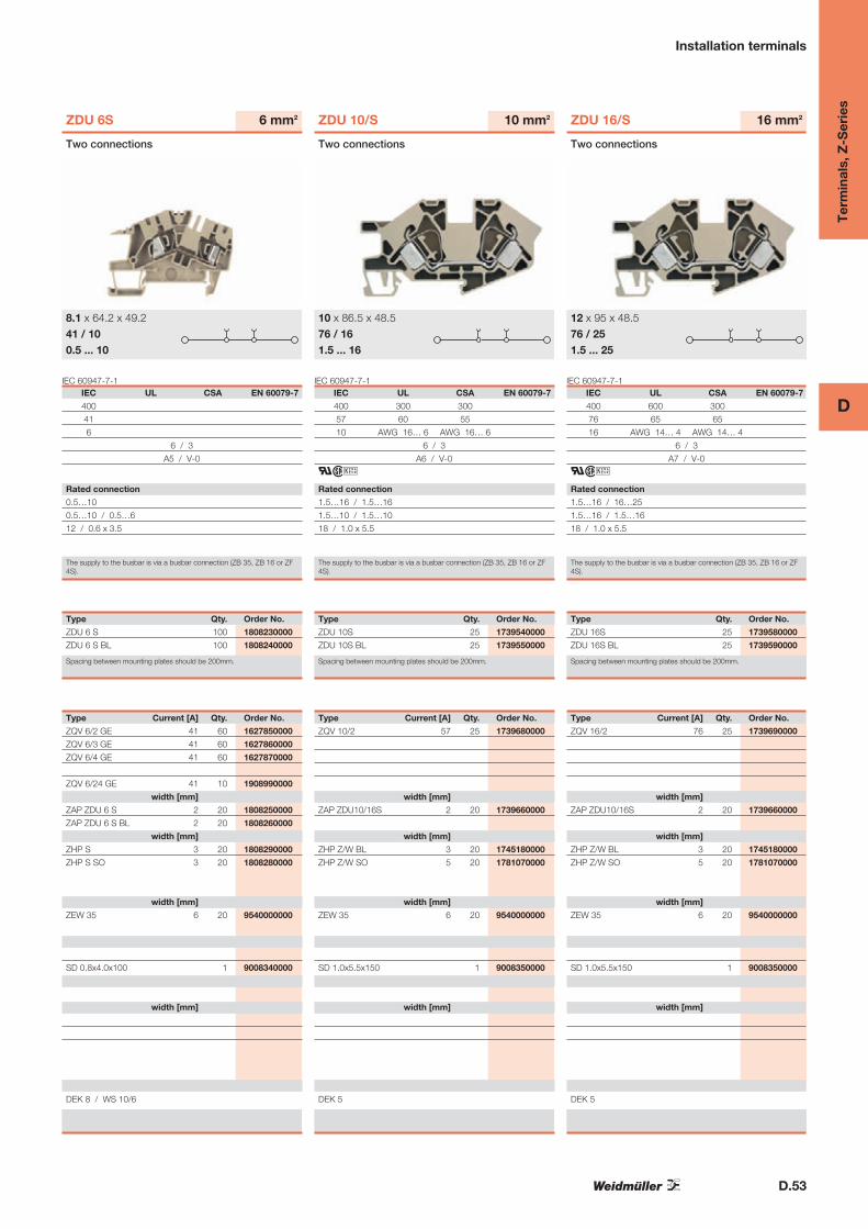
Installation terminals
IEC 60947-7-1
ZDU 6S
IEC UL CSA EN 60079-7
400
41
6
6 / 3
A5 / V-0
Rated connection
0.5…10
0.5…10 / 0.5…6
12 / 0.6 x 3.5
The supply to the busbar is via a busbar connection (ZB 35, ZB 16 or ZF4S).
6 mm2
Two connections
8.1 x 64.2 x 49.241 / 100.5 ... 10
Type Qty. Order No.
ZDU 6 S 100 1808230000
ZDU 6 S BL 100 1808240000
Spacing between mounting plates should be 200mm.
Type Current [A] Qty. Order No.
ZQV 6/2 GE 41 60 1627850000
ZQV 6/3 GE 41 60 1627860000
ZQV 6/4 GE 41 60 1627870000
ZQV 6/24 GE 41 10 1908990000
width [mm]
ZAP ZDU 6 S 2 20 1808250000
ZAP ZDU 6 S BL 2 20 1808260000
width [mm]
ZHP S 3 20 1808290000
ZHP S SO 3 20 1808280000
width [mm]
ZEW 35 6 20 9540000000
SD 0.8x4.0x100 1 9008340000
width [mm]
DEK 8 / WS 10/6
IEC 60947-7-1
ZDU 10/S
IEC UL CSA EN 60079-7
400 300 300
57 60 55
10 AWG 16… 6 AWG 16… 6
6 / 3
A6 / V-0
ari
Rated connection
1.5…16 / 1.5…16
1.5…10 / 1.5…10
18 / 1.0 x 5.5
The supply to the busbar is via a busbar connection (ZB 35, ZB 16 or ZF4S).
10 mm2
Two connections
10 x 86.5 x 48.576 / 161.5 ... 16
Type Qty. Order No.
ZDU 10S 25 1739540000
ZDU 10S BL 25 1739550000
Spacing between mounting plates should be 200mm.
Type Current [A] Qty. Order No.
ZQV 10/2 57 25 1739680000
width [mm]
ZAP ZDU10/16S 2 20 1739660000
width [mm]
ZHP Z/W BL 3 20 1745180000
ZHP Z/W SO 5 20 1781070000
width [mm]
ZEW 35 6 20 9540000000
SD 1.0x5.5x150 1 9008350000
width [mm]
DEK 5
IEC 60947-7-1
ZDU 16/S
IEC UL CSA EN 60079-7
400 600 300
76 65 65
16 AWG 14… 4 AWG 14… 4
6 / 3
A7 / V-0
ari
Rated connection
1.5…16 / 16…25
1.5…16 / 1.5…16
18 / 1.0 x 5.5
The supply to the busbar is via a busbar connection (ZB 35, ZB 16 or ZF4S).
16 mm2
Two connections
12 x 95 x 48.576 / 251.5 ... 25
Type Qty. Order No.
ZDU 16S 25 1739580000
ZDU 16S BL 25 1739590000
Spacing between mounting plates should be 200mm.
Type Current [A] Qty. Order No.
ZQV 16/2 76 25 1739690000
width [mm]
ZAP ZDU10/16S 2 20 1739660000
width [mm]
ZHP Z/W BL 3 20 1745180000
ZHP Z/W SO 5 20 1781070000
width [mm]
ZEW 35 6 20 9540000000
SD 1.0x5.5x150 1 9008350000
width [mm]
DEK 5
D.54
D
Ter
min
als,
Z-S
erie
s
Installation terminals
N-cross-connections with busbar system 10 x 3 mm.
width x length x height with TS 35 x 7.5 mmmax. current / max. cond. cross-section A/mm2
max. clamping range mm2
VDE 0611-5Technical dataRated data
Rated voltage V
Rated current A
Rated cross-section mm2
Rated impulse withstand voltage / Pollution severity kV/-
Gauge to IEC 60947-1 / UL94 Flammability class
Approvals
Clamped conductors (H05V/H07V)
Solid / stranded mm2
Flexible / Flexible with wire end ferrule mm2
Stripping length / Blade size mm / -
Note
Ordering dataVersion
dark beige Wemid
blue Wemid
Note
AccessoriesCross-connection
2-pole
3-pole
4-pole
10-pole
20-/24-pole
End plate / Partition plate
dark beige Wemid
blue Wemid
Mounting plate for 10 x 3 (required every 200 mm)
blue Wemid
for vertical installation position
End bracket
dark beige
Screwdrivers
with cutting device “swifty set”
Standard
Busbar 10 x 3 (140A) (further types in chapter F)
top of busbar to top of TS 35 = 25.5 mm
Tension clamp for supplying 10 x 3 busbars
rigid / flexible 0.5 - 6 / 4mm2
rigid / flexible 6 - 16 / 4mm2
flexible 16 - 35mm2
Marking systems (see large assortment in catalogue 7)
Marking tags
For detailed information on other accessories and appli-cations see “Accessories”
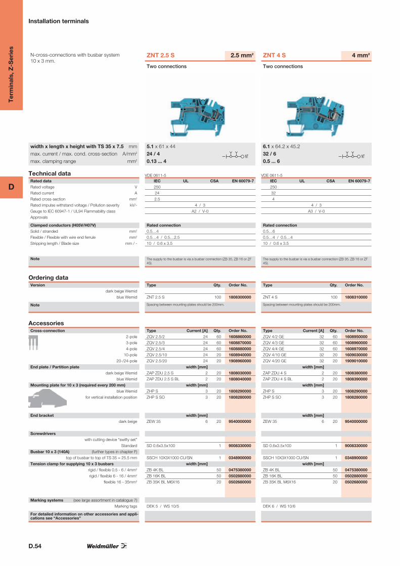
ZNT 2.5 S
IEC UL CSA EN 60079-7
250
24
2.5
4 / 3
A2 / V-0
Rated connection
0.5…4
0.5…4 / 0.5…2.5
10 / 0.6 x 3.5
The supply to the busbar is via a busbar connection (ZB 35, ZB 16 or ZF4S).
2.5 mm2
Two connections
5.1 x 61 x 4424 / 40.13 ... 4
NT
Type Qty. Order No.
ZNT 2.5 S 100 1808300000
Spacing between mounting plates should be 200mm.
Type Current [A] Qty. Order No.
ZQV 2.5/2 24 60 1608860000
ZQV 2.5/3 24 60 1608870000
ZQV 2.5/4 24 60 1608880000
ZQV 2.5/10 24 20 1608940000
ZQV 2.5/20 24 20 1908960000
width [mm]
ZAP ZDU 2.5 S 2 20 1808030000
ZAP ZDU 2.5 S BL 2 20 1808040000
width [mm]
ZHP S 3 20 1808290000
ZHP S SO 3 20 1808280000
width [mm]
ZEW 35 6 20 9540000000
SD 0.6x3.5x100 1 9008330000
SSCH 10X3X1000 CU/SN 1 0348900000
width [mm]
ZB 4K BL 50 0475380000
ZB 16K BL 50 0502880000
ZB 35K BL M6X16 20 0502680000
DEK 5 / WS 10/5
VDE 0611-5
ZNT 4 S
IEC UL CSA EN 60079-7
250
32
4
4 / 3
A3 / V-0
Rated connection
0.5…6
0.5…4 / 0.5…4
10 / 0.6 x 3.5
The supply to the busbar is via a busbar connection (ZB 35, ZB 16 or ZF4S).
4 mm2
Two connections
6.1 x 64.2 x 45.232 / 60.5 ... 6
NT
Type Qty. Order No.
ZNT 4 S 100 1808310000
Spacing between mounting plates should be 200mm.
Type Current [A] Qty. Order No.
ZQV 4/2 GE 32 60 1608950000
ZQV 4/3 GE 32 60 1608960000
ZQV 4/4 GE 32 60 1608970000
ZQV 4/10 GE 32 20 1609030000
ZQV 4/20 GE 32 20 1909010000
width [mm]
ZAP ZDU 4 S 2 20 1808380000
ZAP ZDU 4 S BL 2 20 1808390000
width [mm]
ZHP S 3 20 1808290000
ZHP S SO 3 20 1808280000
width [mm]
ZEW 35 6 20 9540000000
SD 0.6x3.5x100 1 9008330000
SSCH 10X3X1000 CU/SN 1 0348900000
width [mm]
ZB 4K BL 50 0475380000
ZB 16K BL 50 0502880000
ZB 35K BL M6X16 20 0502680000
DEK 6 / WS 10/6
D.55
D
Ter
min
als,
Z-S
erie
s
Installation terminals
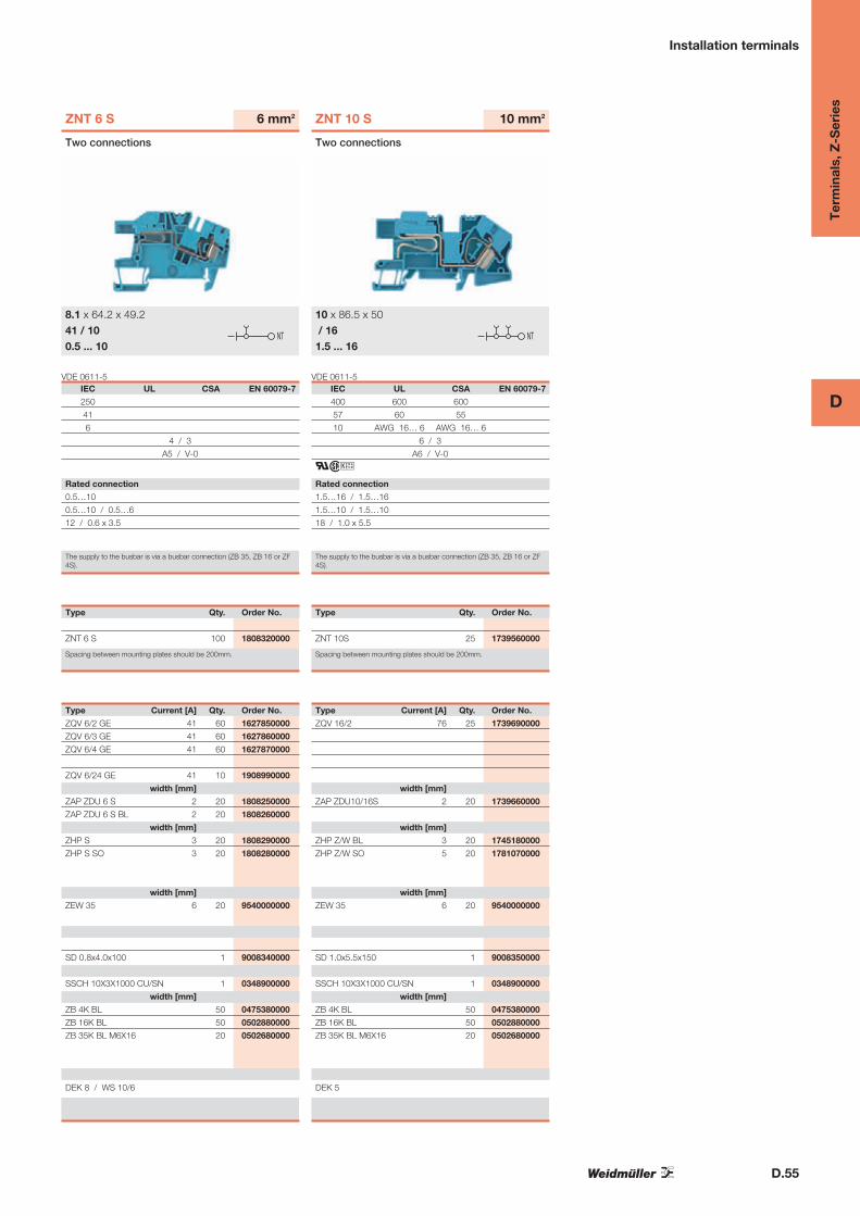
VDE 0611-5
ZNT 6 S
IEC UL CSA EN 60079-7
250
41
6
4 / 3
A5 / V-0
Rated connection
0.5…10
0.5…10 / 0.5…6
12 / 0.6 x 3.5
The supply to the busbar is via a busbar connection (ZB 35, ZB 16 or ZF4S).
6 mm2
Two connections
8.1 x 64.2 x 49.241 / 100.5 ... 10
NT
Type Qty. Order No.
ZNT 6 S 100 1808320000
Spacing between mounting plates should be 200mm.
Type Current [A] Qty. Order No.
ZQV 6/2 GE 41 60 1627850000
ZQV 6/3 GE 41 60 1627860000
ZQV 6/4 GE 41 60 1627870000
ZQV 6/24 GE 41 10 1908990000
width [mm]
ZAP ZDU 6 S 2 20 1808250000
ZAP ZDU 6 S BL 2 20 1808260000
width [mm]
ZHP S 3 20 1808290000
ZHP S SO 3 20 1808280000
width [mm]
ZEW 35 6 20 9540000000
SD 0.8x4.0x100 1 9008340000
SSCH 10X3X1000 CU/SN 1 0348900000
width [mm]
ZB 4K BL 50 0475380000
ZB 16K BL 50 0502880000
ZB 35K BL M6X16 20 0502680000
DEK 8 / WS 10/6
VDE 0611-5
ZNT 10 S
IEC UL CSA EN 60079-7
400 600 600
57 60 55
10 AWG 16… 6 AWG 16… 6
6 / 3
A6 / V-0
ari
Rated connection
1.5…16 / 1.5…16
1.5…10 / 1.5…10
18 / 1.0 x 5.5
The supply to the busbar is via a busbar connection (ZB 35, ZB 16 or ZF4S).
10 mm2
Two connections
10 x 86.5 x 50/ 161.5 ... 16
NT
Type Qty. Order No.
ZNT 10S 25 1739560000
Spacing between mounting plates should be 200mm.
Type Current [A] Qty. Order No.
ZQV 16/2 76 25 1739690000
width [mm]
ZAP ZDU10/16S 2 20 1739660000
width [mm]
ZHP Z/W BL 3 20 1745180000
ZHP Z/W SO 5 20 1781070000
width [mm]
ZEW 35 6 20 9540000000
SD 1.0x5.5x150 1 9008350000
SSCH 10X3X1000 CU/SN 1 0348900000
width [mm]
ZB 4K BL 50 0475380000
ZB 16K BL 50 0502880000
ZB 35K BL M6X16 20 0502680000
DEK 5
D.56
D
Ter
min
als,
Z-S
erie
s
Installation terminals
N-cross-connections with busbar system 10 x 3 mm.
width x length x height with TS 35 x 7.5 mmmax. current / max. cond. cross-section A/mm2
max. clamping range mm2
VDE 0611-5Technical dataRated data
Rated voltage V
Rated current A
Rated cross-section mm2
Rated impulse withstand voltage / Pollution severity kV/-
Gauge to IEC 60947-1 / UL94 Flammability class
Approvals
Clamped conductors (H05V/H07V)
Solid / stranded mm2
Flexible / Flexible with wire end ferrule mm2
Stripping length / Blade size mm / -
Note
Ordering dataVersion
dark beige Wemid
blue Wemid
Note
AccessoriesCross-connection
2-pole
3-pole
4-pole
10-pole
20-/24-pole
End plate / Partition plate
dark beige Wemid
blue Wemid
Mounting plate for 10 x 3 (required every 200 mm)
blue Wemid
for vertical installation position
End bracket
dark beige
Screwdrivers
with cutting device “swifty set”
Standard
Busbar 10 x 3 (140A) (further types in chapter F)
top of busbar to top of TS 35 = 25.5 mm
Tension clamp for supplying 10 x 3 busbars
rigid / flexible 0.5 - 6 / 4mm2
rigid / flexible 6 - 16 / 4mm2
flexible 16 - 35mm2
Marking systems (see large assortment in catalogue 7)
Marking tags
For detailed information on other accessories and appli-cations see “Accessories”
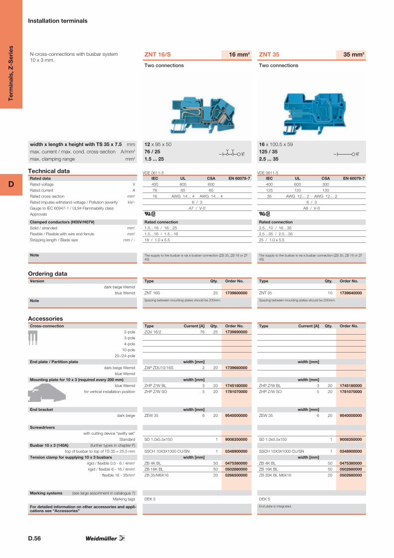
ZNT 16/S
IEC UL CSA EN 60079-7
400 600 600
76 65 65
16 AWG 14… 4 AWG 14… 4
6 / 3
A7 / V-0
ar
Rated connection
1.5…16 / 16…25
1.5…16 / 1.5…16
18 / 1.0 x 5.5
The supply to the busbar is via a busbar connection (ZB 35, ZB 16 or ZF4S).
16 mm2
Two connections
12 x 95 x 5076 / 251.5 ... 25
NT
Type Qty. Order No.
ZNT 16S 25 1739600000
Spacing between mounting plates should be 200mm.
Type Current [A] Qty. Order No.
ZQV 16/2 76 25 1739690000
width [mm]
ZAP ZDU10/16S 2 20 1739660000
width [mm]
ZHP Z/W BL 3 20 1745180000
ZHP Z/W SO 5 20 1781070000
width [mm]
ZEW 35 6 20 9540000000
SD 1.0x5.5x150 1 9008350000
SSCH 10X3X1000 CU/SN 1 0348900000
width [mm]
ZB 4K BL 50 0475380000
ZB 16K BL 50 0502880000
ZB 35/M6X16 20 0266500000
DEK 5
VDE 0611-5
ZNT 35
IEC UL CSA EN 60079-7
400 600 300
125 120 120
35 AWG 12… 2 AWG 12… 2
6 / 3
A8 / V-0
ar
Rated connection
2.5…10 / 16…35
2.5…35 / 2.5…35
25 / 1.0 x 5.5
The supply to the busbar is via a busbar connection (ZB 35, ZB 16 or ZF4S).
35 mm2
Two connections
16 x 100.5 x 59125 / 352.5 ... 35
NT
Type Qty. Order No.
ZNT 35 10 1739640000
Spacing between mounting plates should be 200mm.
Type Current [A] Qty. Order No.
width [mm]
width [mm]
ZHP Z/W BL 3 20 1745180000
ZHP Z/W SO 5 20 1781070000
width [mm]
ZEW 35 6 20 9540000000
SD 1.0x5.5x150 1 9008350000
SSCH 10X3X1000 CU/SN 1 0348900000
width [mm]
ZB 4K BL 50 0475380000
ZB 16K BL 50 0502880000
ZB 35K BL M6X16 20 0502680000
DEK 5
End plate is integrated.

D.57
D
Ter
min
als,
Z-S
erie
s
Installation terminals
VDE 0611-5
ZDU 4 NT
IEC UL CSA EN 60079-7
250 300 300
32 10 10
4 AWG 26… 10 AWG 26… 10
4 / 3
A4 / V-0
ar
Rated connection
0.5…6
0.5…4 / 0.5…4
12 / 0.6 x 3.5
The supply to the busbar is via a busbar connection (ZB 35, ZB 16 or ZF4S).
4 mm2
Modified busbar position
6.1 x 76.3 x 49.532 / 60.5 ... 6
NT
Type Qty. Order No.
ZDU 4/NT DB 50 1778080000
ZDU 4/NT 50 1757980000
Only for use with ZDU 2.5, ZDU 2.5/3 AN, ZDU 4, ZDU 6 and their PE vari-ants.
Type Current [A] Qty. Order No.
width [mm]
ZAP ZDU4/NT 1.5 20 1757970000
width [mm]
ZHP ZDU4/NT SO 5 20 1803890000
width [mm]
ZEW 35 6 20 9540000000
SD 0.6x3.5x100 1 9008330000
SSCH 10X3X1000 CU/SN 1 0348900000
width [mm]
ZB 4K BL 50 0475380000
ZB 16K BL 50 0502880000
ZB 35K BL M6X16 20 0502680000
DEK 5 / WS 15/5
VDE 0611-5
ZDU 10 NT
IEC UL CSA EN 60079-7
250
57
10 AWG 16… 6 AWG 16… 6
4 / 3
A6 / V-0
ar
Rated connection
1.5…10 / 1.5…16
1.5…10 / 1.5…10
18 / 1.0 x 5.5
The supply to the busbar is via a busbar connection (ZB 35, ZB 16 or ZF4S).
10 mm2
Modified busbar position
10 x 86.5 x 5057 / 161.5 ... 16
NT
Type Qty. Order No.
ZDU 10/NT 25 1762420000
Only for use with ZDU 2.5, ZDU 2.5/3 AN, ZDU 4, ZDU 6 and their PE vari-ants.
Type Current [A] Qty. Order No.
ZQV 10/2 57 25 1739680000
width [mm]
ZAP ZDU10/16S 2 20 1739660000
width [mm]
ZHP ZDU4/NT SO 5 20 1803890000
width [mm]
ZEW 35 6 20 9540000000
SD 1.0x5.5x150 1 9008350000
SSCH 10X3X1000 CU/SN 1 0348900000
width [mm]
ZB 4K BL 50 0475380000
ZB 16K BL 50 0502880000
ZB 35K BL M6X16 20 0502680000
DEK 5 / WS 12/5

D.58
D
Ter
min
als,
Z-S
erie
s
Installation terminals
N-cross-connections with busbar system 10 x 3 mm.
width x length x height with TS 35 x 7.5 mmmax. current / max. cond. cross-section A/mm2
max. clamping range mm2
IEC 60947-7-2Technical dataRated data
Rated voltage V
Rated current A
Rated cross-section mm2
Rated impulse withstand voltage / Pollution severity kV/-
Gauge to IEC 60947-1 / UL94 Flammability class
Approvals
Clamped conductors (H05V/H07V)
Solid / stranded mm2
Flexible / Flexible with wire end ferrule mm2
Stripping length / Blade size mm / -
Note
Ordering dataVersion
dark beige Wemid
blue Wemid
Note
AccessoriesCross-connection
2-pole
3-pole
4-pole
10-pole
20-/24-pole
End plate / Partition plate
dark beige Wemid
blue Wemid
Mounting plate for 10 x 3 (required every 200 mm)
blue Wemid
for vertical installation position
End bracket
dark beige
Screwdrivers
with cutting device “swifty set”
Standard
Busbar 10 x 3 (140A) (further types in chapter F)
top of busbar to top of TS 35 = 25.5 mm
Tension clamp for supplying 10 x 3 busbars
rigid / flexible 0.5 - 6 / 4mm2
rigid / flexible 6 - 16 / 4mm2
flexible 16 - 35mm2
Marking systems (see large assortment in catalogue 7)
Marking tags
For detailed information on other accessories and appli-cations see “Accessories”
ZPE 2.5 S
IEC UL CSA EN 60079-7
400
2.5
6 / 3
A2 / V-0
Rated connection
0.5…4
0.5…4 / 0.5…2.5
10 / 0.6 x 3.5
The supply to the busbar is via a busbar connection (ZB 35, ZB 16 or ZF4S).
2.5 mm2
Two connections
5.1 x 61 x 44/ 40.13 ... 4 PE
Type Qty. Order No.
ZPE 2.5 S 100 1808330000
Spacing between mounting plates should be 200mm.
Type Current [A] Qty. Order No.
width [mm]
ZAP ZDU 2.5 S 2 20 1808030000
width [mm]
ZHP S 3 20 1808290000
ZHP S SO 3 20 1808280000
width [mm]
ZEW 35 6 20 9540000000
SD 0.6x3.5x100 1 9008330000
width [mm]
DEK 5 / WS 10/5
IEC 60947-7-2
ZPE 4 S
IEC UL CSA EN 60079-7
400
4
6 / 3
A3 / V-0
Rated connection
0.5…6
0.5…4 / 0.5…4
10 / 0.6 x 3.5
The supply to the busbar is via a busbar connection (ZB 35, ZB 16 or ZF4S).
4 mm2
Two connections
6.1 x 64.2 x 45.2/ 60.5 ... 6 PE
Type Qty. Order No.
ZPE 4 S 100 1808340000
Spacing between mounting plates should be 200mm.
Type Current [A] Qty. Order No.
width [mm]
ZAP ZDU 4 S 2 20 1808380000
width [mm]
ZHP S 3 20 1808290000
ZHP S SO 3 20 1808280000
width [mm]
ZEW 35 6 20 9540000000
SD 0.6x3.5x100 1 9008330000
width [mm]
DEK 6 / WS 10/6
D.59
D
Ter
min
als,
Z-S
erie
s
Installation terminals
IEC 60947-7-2
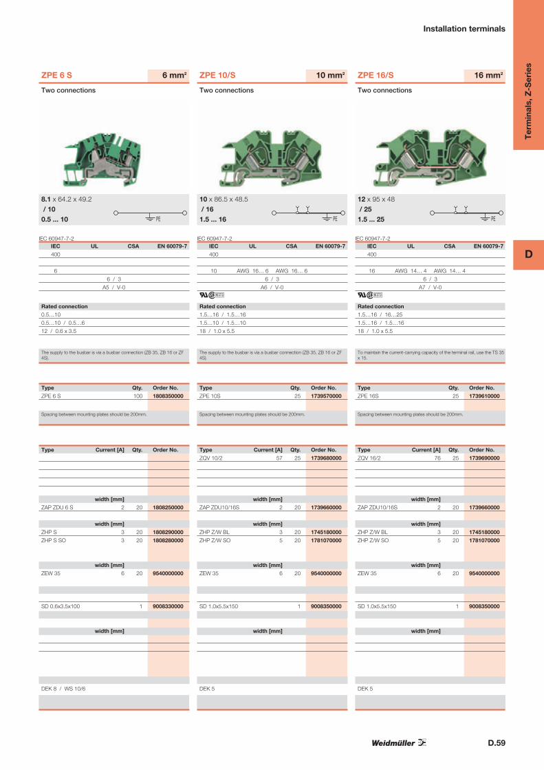
ZPE 6 S
IEC UL CSA EN 60079-7
400
6
6 / 3
A5 / V-0
Rated connection
0.5…10
0.5…10 / 0.5…6
12 / 0.6 x 3.5
The supply to the busbar is via a busbar connection (ZB 35, ZB 16 or ZF4S).
6 mm2
Two connections
8.1 x 64.2 x 49.2/ 100.5 ... 10 PE
Type Qty. Order No.
ZPE 6 S 100 1808350000
Spacing between mounting plates should be 200mm.
Type Current [A] Qty. Order No.
width [mm]
ZAP ZDU 6 S 2 20 1808250000
width [mm]
ZHP S 3 20 1808290000
ZHP S SO 3 20 1808280000
width [mm]
ZEW 35 6 20 9540000000
SD 0.6x3.5x100 1 9008330000
width [mm]
DEK 8 / WS 10/6
IEC 60947-7-2
ZPE 10/S
IEC UL CSA EN 60079-7
400
10 AWG 16… 6 AWG 16… 6
6 / 3
A6 / V-0
ari
Rated connection
1.5…16 / 1.5…16
1.5…10 / 1.5…10
18 / 1.0 x 5.5
The supply to the busbar is via a busbar connection (ZB 35, ZB 16 or ZF4S).
10 mm2
Two connections
10 x 86.5 x 48.5/ 161.5 ... 16 PE
Type Qty. Order No.
ZPE 10S 25 1739570000
Spacing between mounting plates should be 200mm.
Type Current [A] Qty. Order No.
ZQV 10/2 57 25 1739680000
width [mm]
ZAP ZDU10/16S 2 20 1739660000
width [mm]
ZHP Z/W BL 3 20 1745180000
ZHP Z/W SO 5 20 1781070000
width [mm]
ZEW 35 6 20 9540000000
SD 1.0x5.5x150 1 9008350000
width [mm]
DEK 5
IEC 60947-7-2
ZPE 16/S
IEC UL CSA EN 60079-7
400
16 AWG 14… 4 AWG 14… 4
6 / 3
A7 / V-0
ari
Rated connection
1.5…16 / 16…25
1.5…16 / 1.5…16
18 / 1.0 x 5.5
To maintain the current-carrying capacity of the terminal rail, use the TS 35x 15.
16 mm2
Two connections
12 x 95 x 48/ 251.5 ... 25 PE
Type Qty. Order No.
ZPE 16S 25 1739610000
Spacing between mounting plates should be 200mm.
Type Current [A] Qty. Order No.
ZQV 16/2 76 25 1739690000
width [mm]
ZAP ZDU10/16S 2 20 1739660000
width [mm]
ZHP Z/W BL 3 20 1745180000
ZHP Z/W SO 5 20 1781070000
width [mm]
ZEW 35 6 20 9540000000
SD 1.0x5.5x150 1 9008350000
width [mm]
DEK 5

D.60
D
Ter
min
als,
Z-S
erie
s
Installation terminals
N-cross-connections with busbar system 10 x 3 mm.
width x length x height with TS 35 x 7.5 mmmax. current / max. cond. cross-section A/mm2
max. clamping range mm2
IEC 60947-7-1 (-7-2) / VDE 0611-4Technical dataRated data
Rated voltage V
Rated current A
Rated cross-section mm2
Rated impulse withstand voltage / Pollution severity kV/-
Gauge to IEC 60947-1 / UL94 Flammability class
Approvals
Clamped conductors (H05V/H07V)
Solid / stranded mm2
Flexible / Flexible with wire end ferrule mm2
Stripping length / Blade size mm / -
Note
Ordering dataVersion
dark beige Wemid
blue Wemid
Note
AccessoriesCross-connection
2-pole
3-pole
4-pole
10-pole
20-/24-pole
End plate / Partition plate
dark beige Wemid
blue Wemid
Mounting plate for 10 x 3 (required every 200 mm)
blue Wemid
for vertical installation position
End bracket
dark beige
Screwdrivers
with cutting device “swifty set”
Standard
Busbar 10 x 3 (140A) (further types in chapter F)
top of busbar to top of TS 35 = 25.5 mm
Tension clamp for supplying 10 x 3 busbars
rigid / flexible 0.5 - 6 / 4mm2
rigid / flexible 6 - 16 / 4mm2
flexible 16 - 35mm2
Marking systems (see large assortment in catalogue 7)
Marking tags
For detailed information on other accessories and appli-cations see “Accessories”
ZDL 2.5/S/NT/L/PE
IEC UL CSA EN 60079-7
400 300 300
24 10 10
2.5 AWG 26… 12 AWG 26… 12
4 / 3
A2 / V-0
ari
Rated connection
0.5…4
0.5…4 / 0.5…2.5
8 / 0.6 x 3.5
2.5 mm2 flexible conductors with wire end ferrules are crimped with theWeidmüller PZ 6/5 crimping tool.
2.5 mm2
Neutral conductor disconnection - phase - PE
5.1 x 95 x 48.524 / 40.13 ... 4
PE
L
NT
Type Qty. Order No.
ZDL 2.5S/NT/L/PE 50 1720750000
Spacing between mounting plates should be 200mm.
Type Current [A] Qty. Order No.
ZQV 2.5N/2 GE 24 60 1693800000
ZQV 2.5N/3 GE 24 60 1693810000
ZQV 2.5N/4 GE 24 60 1693820000
ZQV 2.5N/10 GE 24 20 1693880000
ZQV 2.5N/20 GE 24 20 1909000000
width [mm]
ZAP ZDL2.5 1.5 20 1720910000
width [mm]
ZHP ZDL2.5S BL 3 20 1720890000
ZHP Z/W SO 5 20 1781070000
width [mm]
ZEW 35 6 20 9540000000
SD 0.6x3.5x100 1 9008330000
SSCH 10X3X1000 CU/SN 1 0348900000
width [mm]
ZB 4K BL 50 0475380000
ZB 16K BL 50 0502880000
ZB 35K BL M6X16 20 0502680000
DEK 5
The supply to the busbar is via a busbar connection (ZB 35, ZB 16 or ZF4S).
IEC 60947-7-1 / VDE 0611-4
ZDL 2.5/S/L/L
IEC UL CSA EN 60079-7
400 300 300
24 10 10
2.5 AWG 26… 12 AWG 26… 12
6 / 3
A2 / V-0
ari
Rated connection
0.5…4
0.5…4 / 0.5…2.5
8 / 0.6 x 3.5
2.5 mm2 flexible conductors with wire end ferrules are crimped with theWeidmüller PZ 6/5 crimping tool.
2.5 mm2
Phase - phase
5.1 x 95 x 48.524 / 40.13 ... 4
L
L
Type Qty. Order No.
ZDL 2.5 S/L/L 50 1720760000
Spacing between mounting plates should be 200mm.
Type Current [A] Qty. Order No.
ZQV 2.5N/2 GE 24 60 1693800000
ZQV 2.5N/3 GE 24 60 1693810000
ZQV 2.5N/4 GE 24 60 1693820000
ZQV 2.5N/10 GE 24 20 1693880000
ZQV 2.5N/20 GE 24 20 1909000000
width [mm]
ZAP ZDL2.5S 1.5 20 1720900000
width [mm]
ZHP ZDL2.5S BL 3 20 1720890000
ZHP Z/W SO 5 20 1781070000
width [mm]
ZEW 35 6 20 9540000000
SD 0.6x3.5x100 1 9008330000
SSCH 10X3X1000 CU/SN 1 0348900000
width [mm]
ZB 4K BL 50 0475380000
ZB 16K BL 50 0502880000
ZB 35K BL M6X16 20 0502680000
DEK 5
The supply to the busbar is via a busbar connection (ZB 35, ZB 16 or ZF4S).

D.61
D
Ter
min
als,
Z-S
erie
s
Installation terminals
IEC 60947-7-1 / VDE 0611-4
ZDL 2.5/S/N
IEC UL CSA EN 60079-7
400 300 300
24 10 10
2.5 AWG 26… 12 AWG 26… 12
6 / 3
A2 / V-0
ari
Rated connection
0.5…4
0.5…4 / 0.5…2.5
8 / 0.6 x 3.5
2.5 mm2 flexible conductors with wire end ferrules are crimped with theWeidmüller PZ 6/5 crimping tool.
2.5 mm2
Neutral conductor
5.1 x 95 x 48.524 / 40.13 ... 4
N
Type Qty. Order No.
ZDL 2.5 S/N 50 1720770000
Spacing between mounting plates should be 200mm.
Type Current [A] Qty. Order No.
ZQV 2.5N/2 GE 24 60 1693800000
ZQV 2.5N/3 GE 24 60 1693810000
ZQV 2.5N/4 GE 24 60 1693820000
ZQV 2.5N/10 GE 24 20 1693880000
ZQV 2.5N/20 GE 24 20 1909000000
width [mm]
ZAP ZDL2.5S 1.5 20 1720900000
width [mm]
ZHP ZDL2.5S BL 3 20 1720890000
ZHP Z/W SO 5 20 1781070000
width [mm]
ZEW 35 6 20 9540000000
SD 0.6x3.5x100 1 9008330000
SSCH 10X3X1000 CU/SN 1 0348900000
width [mm]
ZB 4K BL 50 0475380000
ZB 16K BL 50 0502880000
ZB 35K BL M6X16 20 0502680000
DEK 5
The supply to the busbar is via a busbar connection (ZB 35, ZB 16 or ZF4S).
IEC 60947-7-1
ZDL 2.5/S/L
IEC UL CSA EN 60079-7
400 300 300
24 10 10
2.5 AWG 26… 12 AWG 26… 12
6 / 3
A2 / V-0
ari
Rated connection
0.5…4
0.5…4 / 0.5…2.5
8 / 0.6 x 3.5
2.5 mm2 flexible conductors with wire end ferrules are crimped with theWeidmüller PZ 6/5 crimping tool.
2.5 mm2
Phase
5.1 x 95 x 48.524 / 40.13 ... 4
L
Type Qty. Order No.
ZDL 2.5 S/L 50 1720780000
Spacing between mounting plates should be 200mm.
Type Current [A] Qty. Order No.
ZQV 2.5N/2 GE 24 60 1693800000
ZQV 2.5N/3 GE 24 60 1693810000
ZQV 2.5N/4 GE 24 60 1693820000
ZQV 2.5N/10 GE 24 20 1693880000
ZQV 2.5N/20 GE 24 20 1909000000
width [mm]
ZAP ZDL2.5S 1.5 20 1720900000
width [mm]
ZHP ZDL2.5S BL 3 20 1720890000
ZHP Z/W SO 5 20 1781070000
width [mm]
ZEW 35 6 20 9540000000
SD 0.6x3.5x100 1 9008330000
SSCH 10X3X1000 CU/SN 1 0348900000
width [mm]
ZB 4K BL 50 0475380000
ZB 16K BL 50 0502880000
ZB 35K BL M6X16 20 0502680000
DEK 5
The supply to the busbar is via a busbar connection (ZB 35, ZB 16 or ZF4S).
IEC 60947-7-1 / VDE 0611-4
ZDL 2.5/S/N/L
IEC UL CSA EN 60079-7
400 300 300
24 10 10
2.5 AWG 26… 12 AWG 26… 12
6 / 3
A2 / V-0
ari
Rated connection
0.5…4
0.5…4 / 0.5…2.5
8 / 0.6 x 3.5
2.5 mm2 flexible conductors with wire end ferrules are crimped with theWeidmüller PZ 6/5 crimping tool.
2.5 mm2
Neutral conductor - phase
5.1 x 95 x 48.524 / 40.13 ... 4 L
N
Type Qty. Order No.
ZDL 2.5 S/N/L 50 1720790000
Spacing between mounting plates should be 200mm.
Type Current [A] Qty. Order No.
ZQV 2.5N/2 GE 24 60 1693800000
ZQV 2.5N/3 GE 24 60 1693810000
ZQV 2.5N/4 GE 24 60 1693820000
ZQV 2.5N/10 GE 24 20 1693880000
ZQV 2.5N/20 GE 24 20 1909000000
width [mm]
ZAP ZDL2.5S 1.5 20 1720900000
width [mm]
ZHP ZDL2.5S BL 3 20 1720890000
ZHP Z/W SO 5 20 1781070000
width [mm]
ZEW 35 6 20 9540000000
SD 0.6x3.5x100 1 9008330000
SSCH 10X3X1000 CU/SN 1 0348900000
width [mm]
ZB 4K BL 50 0475380000
ZB 16K BL 50 0502880000
ZB 35K BL M6X16 20 0502680000
DEK 5
The supply to the busbar is via a busbar connection (ZB 35, ZB 16 or ZF4S).

D.62
D
Ter
min
als,
Z-S
erie
s
Installation terminals
N-cross-connections with busbar system 10 x 3 mm.
width x length x height with TS 35 x 7.5 mmmax. current / max. cond. cross-section A/mm2
max. clamping range mm2
IEC 60947-7-1 (-7-2) / VDE 0611-4Technical dataRated data
Rated voltage V
Rated current A
Rated cross-section mm2
Rated impulse withstand voltage / Pollution severity kV/-
Gauge to IEC 60947-1 / UL94 Flammability class
Approvals
Clamped conductors (H05V/H07V)
Solid / stranded mm2
Flexible / Flexible with wire end ferrule mm2
Stripping length / Blade size mm / -
Note
Ordering dataVersion
dark beige Wemid
blue Wemid
Note
AccessoriesCross-connection
2-pole
3-pole
4-pole
10-pole
20-/24-pole
End plate / Partition plate
dark beige Wemid
blue Wemid
Mounting plate for 10 x 3 (required every 200 mm)
blue Wemid
for vertical installation position
End bracket
dark beige
Screwdrivers
with cutting device “swifty set”
Standard
Busbar 10 x 3 (140A) (further types in chapter F)
top of busbar to top of TS 35 = 25.5 mm
Tension clamp for supplying 10 x 3 busbars
rigid / flexible 0.5 - 6 / 4mm2
rigid / flexible 6 - 16 / 4mm2
flexible 16 - 35mm2
Marking systems (see large assortment in catalogue 7)
Marking tags
For detailed information on other accessories and appli-cations see “Accessories”
ZDL 2.5/S/N/L/PE
IEC UL CSA EN 60079-7
400 300 300
24 10 10
2.5 AWG 26… 12 AWG 26… 12
4 / 3
A2 / V-0
ari
Rated connection
0.5…4
0.5…4 / 0.5…2.5
8 / 0.6 x 3.5
2.5 mm2 flexible conductors with wire end ferrules are crimped with theWeidmüller PZ 6/5 crimping tool.
2.5 mm2
Neutral conductor - phase - PE
5.1 x 95 x 48.524 / 40.13 ... 4
L
N
PE
Type Qty. Order No.
ZDL 2.5 S/N/L/PE 50 1720800000
Spacing between mounting plates should be 200mm.
Type Current [A] Qty. Order No.
ZQV 2.5N/2 GE 24 60 1693800000
ZQV 2.5N/3 GE 24 60 1693810000
ZQV 2.5N/4 GE 24 60 1693820000
ZQV 2.5N/10 GE 24 20 1693880000
ZQV 2.5N/20 GE 24 20 1909000000
width [mm]
ZAP ZDL2.5S 1.5 20 1720900000
width [mm]
ZHP ZDL2.5S BL 3 20 1720890000
ZHP Z/W SO 5 20 1781070000
width [mm]
ZEW 35 6 20 9540000000
SD 0.6x3.5x100 1 9008330000
SSCH 10X3X1000 CU/SN 1 0348900000
width [mm]
ZB 4K BL 50 0475380000
ZB 16K BL 50 0502880000
ZB 35K BL M6X16 20 0502680000
DEK 5
The supply to the busbar is via a busbar connection (ZB 35, ZB 16 or ZF4S).
IEC 60947-7-1 (-7-2) / VDE 0611-4
ZDL 2.5/S/L/L/PE
IEC UL CSA EN 60079-7
400 300 300
24 10 10
2.5 AWG 26… 12 AWG 26… 12
4 / 3
A2 / V-0
ari
Rated connection
0.5…4
0.5…4 / 0.5…2.5
8 / 0.6 x 3.5
2.5 mm2 flexible conductors with wire end ferrules are crimped with theWeidmüller PZ 6/5 crimping tool.
2.5 mm2
Phase - phase - PE
5.1 x 95 x 48.524 / 40.13 ... 4
L
L
PE
Type Qty. Order No.
ZDL 2.5 S/L/L/PE 50 1720810000
Spacing between mounting plates should be 200mm.
Type Current [A] Qty. Order No.
ZQV 2.5N/2 GE 24 60 1693800000
ZQV 2.5N/3 GE 24 60 1693810000
ZQV 2.5N/4 GE 24 60 1693820000
ZQV 2.5N/10 GE 24 20 1693880000
ZQV 2.5N/20 GE 24 20 1909000000
width [mm]
ZAP ZDL2.5S 1.5 20 1720900000
width [mm]
ZHP ZDL2.5S BL 3 20 1720890000
ZHP Z/W SO 5 20 1781070000
width [mm]
ZEW 35 6 20 9540000000
SD 0.6x3.5x100 1 9008330000
SSCH 10X3X1000 CU/SN 1 0348900000
width [mm]
ZB 4K BL 50 0475380000
ZB 16K BL 50 0502880000
ZB 35K BL M6X16 20 0502680000
DEK 5
The supply to the busbar is via a busbar connection (ZB 35, ZB 16 or ZF4S).
D.63
D
Ter
min
als,
Z-S
erie
s
Installation terminals
Electrical distribution with plug-in cross-connec-tion
When using ATEX certified components in hazardous area ap-
plications the installation instructions and the rated data for
accessories in the technical appendix must be considered.
width x length x height with TS 35 x 7.5 mmmax. current / max. cond. cross-section A/mm2
max. clamping range mm2
IEC 60947-7-1 (-7-2) / VDE 0611-4Technical dataRated data
Rated voltage V
Rated current A
Rated cross-section mm2
Rated impulse withstand voltage / Pollution severity kV/-
Gauge to IEC 60947-1 / UL94 Flammability class
Approvals
Clamped conductors (H05V/H07V)
Solid / stranded mm2
Flexible / Flexible with wire end ferrule mm2
Tightening torque range (clamping screw) Nm
Stripping length / Blade size mm / -
Note
Ordering dataVersion
dark beige Wemid
blue Wemid
Note
AccessoriesCross-connection, pluggable
2-pole
3-pole
4-pole
10-pole
20-/24-pole
End plate / Partition plate
dark beige Wemid
blue Wemid
End bracket
dark beige Wemid
Test adapter
For testing wired terminal strips Standard
with spigot
Screwdrivers
with cutting device “swifty set”
Standard
Reducing sleeves
for conductors < 0.5 mm / AWG 20
for conductors < 1.0 mm / AWG 18
Cover
with lightning flash symbol
blank
Labelling systems (see large assortment in catalogue 7)
Marking tags
For detailed information on other accessories and appli-cations see “Accessories”
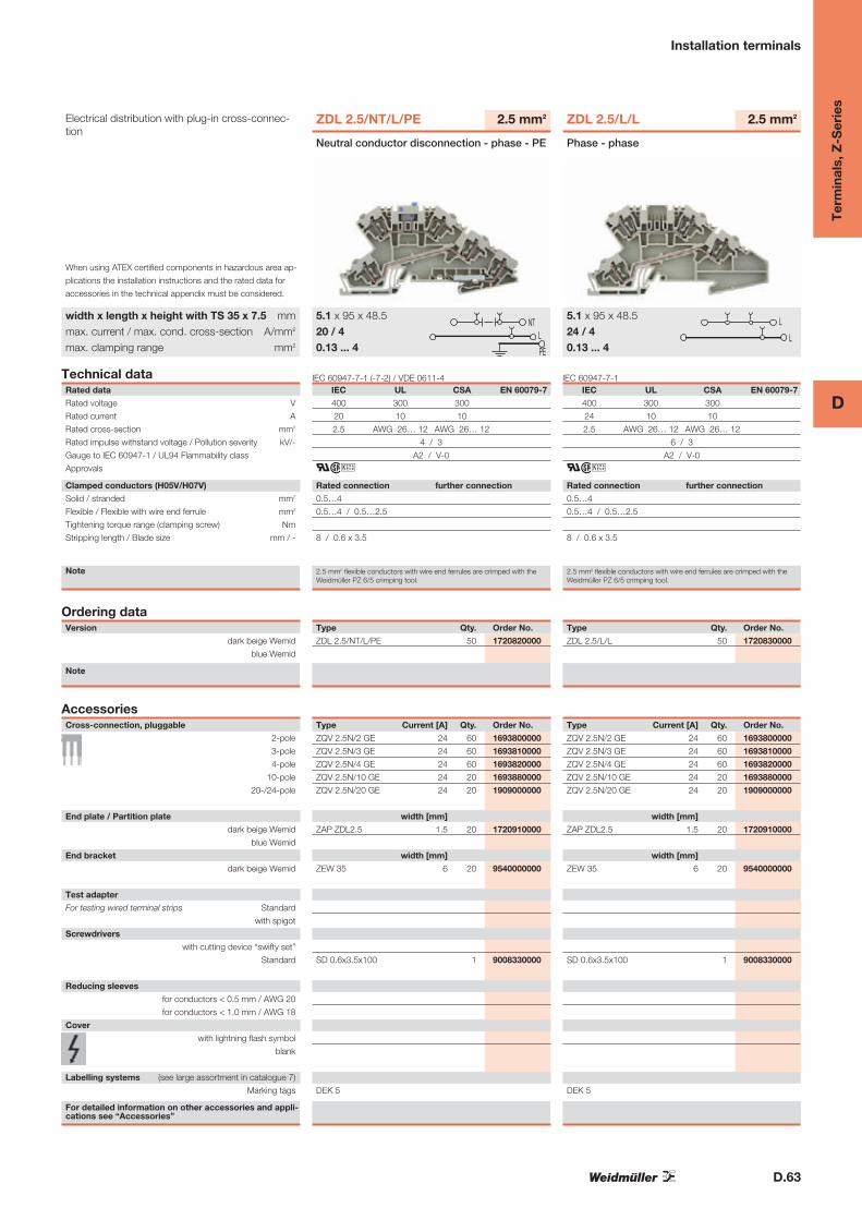
ZDL 2.5/NT/L/PE
IEC UL CSA EN 60079-7
400 300 300
20 10 10
2.5 AWG 26… 12 AWG 26… 12
4 / 3
A2 / V-0
ari
Rated connection further connection
0.5…4
0.5…4 / 0.5…2.5
8 / 0.6 x 3.5
2.5 mm2 flexible conductors with wire end ferrules are crimped with theWeidmüller PZ 6/5 crimping tool.
2.5 mm2
5.1 x 95 x 48.520 / 40.13 ... 4
Neutral conductor disconnection - phase - PE
L
NT
PE
Type Qty. Order No.
ZDL 2.5/NT/L/PE 50 1720820000
Type Current [A] Qty. Order No.
ZQV 2.5N/2 GE 24 60 1693800000
ZQV 2.5N/3 GE 24 60 1693810000
ZQV 2.5N/4 GE 24 60 1693820000
ZQV 2.5N/10 GE 24 20 1693880000
ZQV 2.5N/20 GE 24 20 1909000000
width [mm]
ZAP ZDL2.5 1.5 20 1720910000
width [mm]
ZEW 35 6 20 9540000000
SD 0.6x3.5x100 1 9008330000
DEK 5
IEC 60947-7-1
ZDL 2.5/L/L
IEC UL CSA EN 60079-7
400 300 300
24 10 10
2.5 AWG 26… 12 AWG 26… 12
6 / 3
A2 / V-0
ari
Rated connection further connection
0.5…4
0.5…4 / 0.5…2.5
8 / 0.6 x 3.5
2.5 mm2 flexible conductors with wire end ferrules are crimped with theWeidmüller PZ 6/5 crimping tool.
2.5 mm2
5.1 x 95 x 48.524 / 40.13 ... 4
Phase - phase
L
L
Type Qty. Order No.
ZDL 2.5/L/L 50 1720830000
Type Current [A] Qty. Order No.
ZQV 2.5N/2 GE 24 60 1693800000
ZQV 2.5N/3 GE 24 60 1693810000
ZQV 2.5N/4 GE 24 60 1693820000
ZQV 2.5N/10 GE 24 20 1693880000
ZQV 2.5N/20 GE 24 20 1909000000
width [mm]
ZAP ZDL2.5 1.5 20 1720910000
width [mm]
ZEW 35 6 20 9540000000
SD 0.6x3.5x100 1 9008330000
DEK 5
D.64
D
Ter
min
als,
Z-S
erie
s
Installation terminals
Electrical distribution with plug-in cross-connec-tion
When using ATEX certified components in hazardous area ap-
plications the installation instructions and the rated data for
accessories in the technical appendix must be considered.
width x length x height with TS 35 x 7.5 mmmax. current / max. cond. cross-section A/mm2
max. clamping range mm2
IEC 60947-7-1Technical dataRated data
Rated voltage V
Rated current A
Rated cross-section mm2
Rated impulse withstand voltage / Pollution severity kV/-
Gauge to IEC 60947-1 / UL94 Flammability class
Approvals
Clamped conductors (H05V/H07V)
Solid / stranded mm2
Flexible / Flexible with wire end ferrule mm2
Tightening torque range (clamping screw) Nm
Stripping length / Blade size mm / -
Note
Ordering dataVersion
dark beige Wemid
blue Wemid
Note
AccessoriesCross-connection, pluggable
2-pole
3-pole
4-pole
10-pole
20-/24-pole
End plate / Partition plate
dark beige Wemid
blue Wemid
End bracket
dark beige Wemid
Test adapter
For testing wired terminal strips Standard
with spigot
Screwdrivers
with cutting device “swifty set”
Standard
Reducing sleeves
for conductors < 0.5 mm / AWG 20
for conductors < 1.0 mm / AWG 18
Cover
with lightning flash symbol
blank
Labelling systems (see large assortment in catalogue 7)
Marking tags
For detailed information on other accessories and appli-cations see “Accessories”
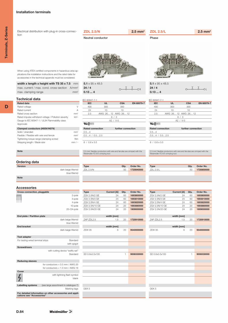
ZDL 2.5/N
IEC UL CSA EN 60079-7
400 300 300
24 10 10
2.5 AWG 26… 12 AWG 26… 12
6 / 3
A2 / V-0
ari
Rated connection further connection
0.5…4
0.5…4 / 0.5…2.5
8 / 0.6 x 3.5
2.5 mm2 flexible conductors with wire end ferrules are crimped with theWeidmüller PZ 6/5 crimping tool.
2.5 mm2
5.1 x 95 x 48.524 / 40.13 ... 4
Neutral conductor
N
Type Qty. Order No.
ZDL 2.5/N 50 1720840000
Type Current [A] Qty. Order No.
ZQV 2.5N/2 GE 24 60 1693800000
ZQV 2.5N/3 GE 24 60 1693810000
ZQV 2.5N/4 GE 24 60 1693820000
ZQV 2.5N/10 GE 24 20 1693880000
ZQV 2.5N/20 GE 24 20 1909000000
width [mm]
ZAP ZDL2.5 1.5 20 1720910000
width [mm]
ZEW 35 6 20 9540000000
SD 0.6x3.5x100 1 9008330000
DEK 5
IEC 60947-7-1
ZDL 2.5/L
IEC UL CSA EN 60079-7
400 300 300
24 10 10
2.5 AWG 26… 12 AWG 26… 12
6 / 3
A2 / V-0
ari
Rated connection further connection
0.5…4
0.5…4 / 0.5…2.5
8 / 0.6 x 3.5
2.5 mm2 flexible conductors with wire end ferrules are crimped with theWeidmüller PZ 6/5 crimping tool.
2.5 mm2
5.1 x 95 x 48.524 / 40.13 ... 4
Phase
L
Type Qty. Order No.
ZDL 2.5/L 50 1720850000
Type Current [A] Qty. Order No.
ZQV 2.5N/2 GE 24 60 1693800000
ZQV 2.5N/3 GE 24 60 1693810000
ZQV 2.5N/4 GE 24 60 1693820000
ZQV 2.5N/10 GE 24 20 1693880000
ZQV 2.5N/20 GE 24 20 1909000000
width [mm]
ZAP ZDL2.5 1.5 20 1720910000
width [mm]
ZEW 35 6 20 9540000000
SD 0.6x3.5x100 1 9008330000
DEK 5

D.65
D
Ter
min
als,
Z-S
erie
s
Installation terminals
IEC 60947-7-1
ZDL 2.5/N/L
IEC UL CSA EN 60079-7
400 300 300
24 10 10
2.5 AWG 26… 12 AWG 26… 12
6 / 3
A2 / V-0
ari
Rated connection further connection
0.5…4
0.5…4 / 0.5…2.5
8 / 0.6 x 3.5
2.5 mm2 flexible conductors with wire end ferrules are crimped with theWeidmüller PZ 6/5 crimping tool.
2.5 mm2
5.1 x 95 x 48.524 / 40.13 ... 4
Neutral conductor - phase
L
N
Type Qty. Order No.
ZDL 2.5/N/L 50 1720860000
Type Current [A] Qty. Order No.
ZQV 2.5N/2 GE 24 60 1693800000
ZQV 2.5N/3 GE 24 60 1693810000
ZQV 2.5N/4 GE 24 60 1693820000
ZQV 2.5N/10 GE 24 20 1693880000
ZQV 2.5N/20 GE 24 20 1909000000
width [mm]
ZAP ZDL2.5 1.5 20 1720910000
width [mm]
ZEW 35 6 20 9540000000
SD 0.6x3.5x100 1 9008330000
DEK 5
IEC 60947-7-1 (-7-2)
ZDL 2.5/N/L/PE
IEC UL CSA EN 60079-7
400 300 300
24 10 10
2.5 AWG 26… 12 AWG 26… 12
4 / 3
A2 / V-0
i
Rated connection further connection
0.5…4
0.5…4 / 0.5…2.5
8 / 0.6 x 3.5
2.5 mm2 flexible conductors with wire end ferrules are crimped with theWeidmüller PZ 6/5 crimping tool.
2.5 mm2
5.1 x 95 x 48.524 / 40.13 ... 4
Neutral conductor - phase - PE
L
N
PE
Type Qty. Order No.
ZDL 2.5/N/L/PE 50 1720870000
Type Current [A] Qty. Order No.
ZQV 2.5N/2 GE 24 60 1693800000
ZQV 2.5N/3 GE 24 60 1693810000
ZQV 2.5N/4 GE 24 60 1693820000
ZQV 2.5N/10 GE 24 20 1693880000
ZQV 2.5N/20 GE 24 20 1909000000
width [mm]
ZAP ZDL2.5 1.5 20 1720910000
width [mm]
ZEW 35 6 20 9540000000
SD 0.6x3.5x100 1 9008330000
DEK 5
IEC 60947-7-1 (-7-2)
ZDL 2.5/L/L/PE
IEC UL CSA EN 60079-7
400 300 300
24 10 10
2.5 AWG 26… 12 AWG 26… 12
4 / 3
A2 / V-0
ari
Rated connection further connection
0.5…4
0.5…4 / 0.5…2.5
8 / 0.6 x 3.5
2.5 mm2 flexible conductors with wire end ferrules are crimped with theWeidmüller PZ 6/5 crimping tool.
2.5 mm2
5.1 x 95 x 48.524 / 40.13 ... 4
Phase - phase - PE
L
L
PE
Type Qty. Order No.
ZDL 2.5/L/L/PE 50 1720880000
Type Current [A] Qty. Order No.
ZQV 2.5N/2 GE 24 60 1693800000
ZQV 2.5N/3 GE 24 60 1693810000
ZQV 2.5N/4 GE 24 60 1693820000
ZQV 2.5N/10 GE 24 20 1693880000
ZQV 2.5N/20 GE 24 20 1909000000
width [mm]
ZAP ZDL2.5 1.5 20 1720910000
width [mm]
ZEW 35 6 20 9540000000
SD 0.6x3.5x100 1 9008330000
DEK 5

D.66
D
Ter
min
als,
Z-S
erie
s
Installation terminals
N-cross-connections with busbar system 10 x 3 mm.
width x length x height with TS 35 x 7.5 mmmax. current / max. cond. cross-section A/mm2
max. clamping range mm2
IEC 60947-7-1Technical dataRated data
Rated voltage V
Rated current A
Rated cross-section mm2
Rated impulse withstand voltage / Pollution severity kV/-
Gauge to IEC 60947-1 / UL94 Flammability class
Approvals
Clamped conductors (H05V/H07V)
Solid / stranded mm2
Flexible / Flexible with wire end ferrule mm2
Stripping length / Blade size mm / -
Note
Ordering dataVersion
dark beige Wemid
blue Wemid
Note
AccessoriesCross-connection
2-pole
3-pole
4-pole
10-pole
20-/24-pole
End plate / Partition plate
dark beige Wemid
blue Wemid
Mounting plate for 10 x 3 (required every 200 mm)
blue Wemid
for vertical installation position
End bracket
dark beige
Screwdrivers
with cutting device “swifty set”
Standard
Busbar 10 x 3 (140A) (further types in chapter F)
top of busbar to top of TS 35 = 25.5 mm
Tension clamp for supplying 10 x 3 busbars
rigid / flexible 0.5 - 6 / 4mm2
rigid / flexible 6 - 16 / 4mm2
flexible 16 - 35mm2
Marking systems (see large assortment in catalogue 7)
Marking tags
For detailed information on other accessories and appli-cations see “Accessories”
ZDK 4/S/L/L
IEC UL CSA EN 60079-7
400 300
32 33
4 AWG 26… 10
6 / 3
A4 / V-0
Rated connection
0.5…6
0.5…4 / 0.5…4
12 / 0.6 x 3.5
The supply to the busbar is via a busbar connection (ZB 35, ZB 16 or ZF4S).
4 mm2
Phase - phase
6.1 x 122 x 50.532 / 60.13 ... 6
L
L
Type Qty. Order No.
ZDK 4S/L/L 50 1733290000
Spacing between mounting plates should be 200mm.
Type Current [A] Qty. Order No.
ZQV 4/2 GE 32 60 1608950000
ZQV 4/3 GE 32 60 1608960000
ZQV 4/4 GE 32 60 1608970000
ZQV 4/10 GE 32 20 1609030000
ZQV 4/20 GE 32 20 1909010000
width [mm]
ZAP ZDK4/6S 2 20 1733240000
width [mm]
ZHP Z/W BL 3 20 1745180000
ZHP Z/W SO 5 20 1781070000
width [mm]
ZEW 35 6 20 9540000000
SD 0.6x3.5x100 1 9008330000
SSCH 10X3X1000 CU/SN 1 0348900000
width [mm]
ZB 4K BL 50 0475380000
ZB 16K BL 50 0502880000
ZB 35K BL M6X16 20 0502680000
DEK 5
IEC 60947-7-1
ZDK 4/ S/N/L
IEC UL CSA EN 60079-7
400 300
32 33
4 AWG 26… 10
6 / 3
A4 / V-0
Rated connection
0.5…6
0.5…4 / 0.5…4
12 / 0.6 x 3.5
The supply to the busbar is via a busbar connection (ZB 35, ZB 16 or ZF4S).
4 mm2
Neutral conductor - phase
6.1 x 122 x 50.532 / 60.13 ... 6
L
N
Type Qty. Order No.
ZDK 4S/N/L 50 1733460000
Spacing between mounting plates should be 200mm.
Type Current [A] Qty. Order No.
ZQV 4/2 GE 32 60 1608950000
ZQV 4/3 GE 32 60 1608960000
ZQV 4/4 GE 32 60 1608970000
ZQV 4/10 GE 32 20 1609030000
ZQV 4/20 GE 32 20 1909010000
width [mm]
ZAP ZDK4/6S 2 20 1733240000
width [mm]
ZHP Z/W BL 3 20 1745180000
ZHP Z/W SO 5 20 1781070000
width [mm]
ZEW 35 6 20 9540000000
SD 0.6x3.5x100 1 9008330000
SSCH 10X3X1000 CU/SN 1 0348900000
width [mm]
ZB 4K BL 50 0475380000
ZB 16K BL 50 0502880000
ZB 35K BL M6X16 20 0502680000
DEK 5

D.67
D
Ter
min
als,
Z-S
erie
s
Installation terminals
IEC 60947-7-1 / VDE 0611-4
ZDK 4/S/NT
IEC UL CSA EN 60079-7
250
32
4
4 / 3
A4 / V-0
Rated connection
0.5…6
0.5…4 / 0.5…4
12 / 0.6 x 3.5
The supply to the busbar is via a busbar connection (ZB 35, ZB 16 or ZF4S).
4 mm2
Neutral conductor disconnection
6.1 x 122 x 50.532 / 60.13 ... 6
NT
Type Qty. Order No.
ZDK 4S/NT 50 1733280000
Spacing between mounting plates should be 200mm.
Type Current [A] Qty. Order No.
ZQV 4/2 GE 32 60 1608950000
ZQV 4/3 GE 32 60 1608960000
ZQV 4/4 GE 32 60 1608970000
ZQV 4/10 GE 32 20 1609030000
ZQV 4/20 GE 32 20 1909010000
width [mm]
ZAP ZDK4/6S 2 20 1733240000
width [mm]
ZHP Z/W BL 3 20 1745180000
ZHP Z/W SO 5 20 1781070000
width [mm]
ZEW 35 6 20 9540000000
SD 0.6x3.5x100 1 9008330000
SSCH 10X3X1000 CU/SN 1 0348900000
width [mm]
ZB 4K BL 50 0475380000
ZB 16K BL 50 0502880000
ZB 35K BL M6X16 20 0502680000
DEK 5
IEC 60947-7-1
ZDK 4/S/N
IEC UL CSA EN 60079-7
400
32
4
6 / 3
A4 / V-0
Rated connection
0.5…6
0.5…4 / 0.5…4
12 / 0.6 x 3.5
The supply to the busbar is via a busbar connection (ZB 35, ZB 16 or ZF4S).
4 mm2
Neutral conductor
6.1 x 122 x 50.532 / 60.13 ... 6
N
Type Qty. Order No.
ZDK 4S/N 50 1733450000
Spacing between mounting plates should be 200mm.
Type Current [A] Qty. Order No.
ZQV 4/2 GE 32 60 1608950000
ZQV 4/3 GE 32 60 1608960000
ZQV 4/4 GE 32 60 1608970000
ZQV 4/10 GE 32 20 1609030000
ZQV 4/20 GE 32 20 1909010000
width [mm]
ZAP ZDK4/6S 2 20 1733240000
width [mm]
ZHP Z/W BL 3 20 1745180000
ZHP Z/W SO 5 20 1781070000
width [mm]
ZEW 35 6 20 9540000000
SD 0.6x3.5x100 1 9008330000
SSCH 10X3X1000 CU/SN 1 0348900000
width [mm]
ZB 4K BL 50 0475380000
ZB 16K BL 50 0502880000
ZB 35K BL M6X16 20 0502680000
DEK 5
IEC 60947-7-1 (-7-2)
ZDK 4/S/L/PE
IEC UL CSA EN 60079-7
400
32
4
6 / 3
A4 / V-0
Rated connection
0.5…6
0.5…4 / 0.5…4
12 / 0.6 x 3.5
The supply to the busbar is via a busbar connection (ZB 35, ZB 16 or ZF4S).
4 mm2
Phase - PE conductor
6.1 x 122 x 50.532 / 60.13 ... 6
L
PE
Type Qty. Order No.
ZDK 4S/L/PE 50 1733300000
Spacing between mounting plates should be 200mm.
Type Current [A] Qty. Order No.
ZQV 4/2 GE 32 60 1608950000
ZQV 4/3 GE 32 60 1608960000
ZQV 4/4 GE 32 60 1608970000
ZQV 4/10 GE 32 20 1609030000
ZQV 4/20 GE 32 20 1909010000
width [mm]
ZAP ZDK4/6S 2 20 1733240000
width [mm]
ZHP Z/W BL 3 20 1745180000
ZHP Z/W SO 5 20 1781070000
width [mm]
ZEW 35 6 20 9540000000
SD 0.6x3.5x100 1 9008330000
SSCH 10X3X1000 CU/SN 1 0348900000
width [mm]
ZB 4K BL 50 0475380000
ZB 16K BL 50 0502880000
ZB 35K BL M6X16 20 0502680000
DEK 5

D.68
D
Ter
min
als,
Z-S
erie
s
Installation terminals
N-cross-connections with busbar system 10 x 3 mm.
width x length x height with TS 35 x 7.5 mmmax. current / max. cond. cross-section A/mm2
max. clamping range mm2
IEC 60947-7-1 (-7-2)Technical dataRated data
Rated voltage V
Rated current A
Rated cross-section mm2
Rated impulse withstand voltage / Pollution severity kV/-
Gauge to IEC 60947-1 / UL94 Flammability class
Approvals
Clamped conductors (H05V/H07V)
Solid / stranded mm2
Flexible / Flexible with wire end ferrule mm2
Stripping length / Blade size mm / -
Note
Ordering dataVersion
dark beige Wemid
blue Wemid
Note
AccessoriesCross-connection
2-pole
3-pole
4-pole
10-pole
20-/24-pole
End plate / Partition plate
dark beige Wemid
blue Wemid
Mounting plate for 10 x 3 (required every 200 mm)
blue Wemid
for vertical installation position
End bracket
dark beige
Screwdrivers
with cutting device “swifty set”
Standard
Busbar 10 x 3 (140A) (further types in chapter F)
top of busbar to top of TS 35 = 25.5 mm
Tension clamp for supplying 10 x 3 busbars
rigid / flexible 0.5 - 6 / 4mm2
rigid / flexible 6 - 16 / 4mm2
flexible 16 - 35mm2
Marking systems (see large assortment in catalogue 7)
Marking tags
For detailed information on other accessories and appli-cations see “Accessories”
ZDK 4/S/N/PE
IEC UL CSA EN 60079-7
400
32
4
6 / 3
A4 / V-0
Rated connection
0.5…6
0.5…6 / 0.5…4
12 / 0.6 x 3.5
The supply to the busbar is via a busbar connection (ZB 35, ZB 16 or ZF4S).
4 mm2
Neutral conductor - PE
6.1 x 122 x 50.532 / 60.13 ... 6
N
PE
Type Qty. Order No.
ZDK 4S/N/PE 50 1733470000
Spacing between mounting plates should be 200mm.
Type Current [A] Qty. Order No.
ZQV 4/2 GE 32 60 1608950000
ZQV 4/3 GE 32 60 1608960000
ZQV 4/4 GE 32 60 1608970000
ZQV 4/10 GE 32 20 1609030000
ZQV 4/20 GE 32 20 1909010000
width [mm]
ZAP ZDK4/6S 2 20 1733240000
width [mm]
ZHP Z/W BL 3 20 1745180000
ZHP Z/W SO 5 20 1781070000
width [mm]
ZEW 35 6 20 9540000000
SD 0.6x3.5x100 1 9008330000
SSCH 10X3X1000 CU/SN 1 0348900000
width [mm]
ZB 4K BL 50 0475380000
ZB 16K BL 50 0502880000
ZB 35K BL M6X16 20 0502680000
DEK 5
IEC 60947-7-1
ZDK 6/S/L/L
IEC UL CSA EN 60079-7
400 300
41 38
6 AWG 22… 8
6 / 3
A5 / V-0
Rated connection
0.5…10
0.5…6 / 0.5…6
12 / 1.0 x 5.5
The supply to the busbar is via a busbar connection (ZB 35, ZB 16 or ZF4S).
6 mm2
Phase - phase
8.1 x 124 x 50.541 / 100.33 ... 10
L
L
Type Qty. Order No.
ZDK 6S/L/L 25 1733260000
Spacing between mounting plates should be 200mm.
Type Current [A] Qty. Order No.
ZQV 6/2 GE 41 60 1627850000
ZQV 6/3 GE 41 60 1627860000
ZQV 6/4 GE 41 60 1627870000
ZQV 6/24 GE 41 10 1908990000
width [mm]
ZAP ZDK4/6S 2 20 1733240000
width [mm]
ZHP Z/W BL 3 20 1745180000
ZHP Z/W SO 5 20 1781070000
width [mm]
ZEW 35 6 20 9540000000
SD 1.0x5.5x150 1 9008350000
SSCH 10X3X1000 CU/SN 1 0348900000
width [mm]
ZB 4K BL 50 0475380000
ZB 16K BL 50 0502880000
ZB 35K BL M6X16 20 0502680000
DEK 8

D.69
D
Ter
min
als,
Z-S
erie
s
Installation terminals
IEC 60947-7-1
ZDK 6/S/N/L
IEC UL CSA EN 60079-7
400 300
41 38
6 AWG 22… 8
6 / 3
A5 / V-0
Rated connection
0.5…6
0.5…6 / 0.5…6
12 / 1.0 x 5.5
The supply to the busbar is via a busbar connection (ZB 35, ZB 16 or ZF4S).
6 mm2
Neutral conductor - phase
8 x 124 x 50.541 / 100.21 ... 10
L
N
Type Qty. Order No.
ZDK 6S/N/L 25 1733490000
Spacing between mounting plates should be 200mm.
Type Current [A] Qty. Order No.
ZQV 6/2 GE 41 60 1627850000
ZQV 6/3 GE 41 60 1627860000
ZQV 6/4 GE 41 60 1627870000
ZQV 6/24 GE 41 10 1908990000
width [mm]
ZAP ZDK4/6S 2 20 1733240000
width [mm]
ZHP Z/W BL 3 20 1745180000
ZHP Z/W SO 5 20 1781070000
width [mm]
ZEW 35 6 20 9540000000
SD 1.0x5.5x150 1 9008350000
SSCH 10X3X1000 CU/SN 1 0348900000
width [mm]
ZB 4K BL 50 0475380000
ZB 16K BL 50 0502880000
ZB 35K BL M6X16 20 0502680000
DEK 8
IEC 60947-7-1 / VDE 0611-4
ZDK 6/S/NT
IEC UL CSA EN 60079-7
250
41
6
4 / 3
A5 / V-0
Rated connection
0.5…10
0.5…6 / 0.5…6
12 / 1.0 x 5.5
The supply to the busbar is via a busbar connection (ZB 35, ZB 16 or ZF4S).
6 mm2
Neutral conductor disconnection
8.1 x 124 x 50.541 / 100.33 ... 10
NT
Type Qty. Order No.
ZDK 6S/NT 25 1733250000
Spacing between mounting plates should be 200mm.
Type Current [A] Qty. Order No.
ZQV 6/2 GE 41 60 1627850000
ZQV 6/3 GE 41 60 1627860000
ZQV 6/4 GE 41 60 1627870000
ZQV 6/24 GE 41 10 1908990000
width [mm]
ZAP ZDK4/6S 2 20 1733240000
width [mm]
ZHP Z/W BL 3 20 1745180000
ZHP Z/W SO 5 20 1781070000
width [mm]
ZEW 35 6 20 9540000000
SD 1.0x5.5x150 1 9008350000
SSCH 10X3X1000 CU/SN 1 0348900000
width [mm]
ZB 4K BL 50 0475380000
ZB 16K BL 50 0502880000
ZB 35K BL M6X16 20 0502680000
DEK 8
IEC 60947-7-1
ZDK 6/S/N
IEC UL CSA EN 60079-7
400
41
6
6 / 3
A5 / V-0
Rated connection
0.5…10
0.5…6 / 0.5…6
12 / 1.0 x 5.5
The supply to the busbar is via a busbar connection (ZB 35, ZB 16 or ZF4S).
6 mm2
Neutral conductor
8.1 x 124 x 50.541 / 100.33 ... 10
N
Type Qty. Order No.
ZDK 6S/N 25 1733480000
Spacing between mounting plates should be 200mm.
Type Current [A] Qty. Order No.
ZQV 6/2 GE 41 60 1627850000
ZQV 6/3 GE 41 60 1627860000
ZQV 6/4 GE 41 60 1627870000
ZQV 6/24 GE 41 10 1908990000
width [mm]
ZAP ZDK4/6S 2 20 1733240000
width [mm]
ZHP Z/W BL 3 20 1745180000
ZHP Z/W SO 5 20 1781070000
width [mm]
ZEW 35 6 20 9540000000
SD 1.0x5.5x150 1 9008350000
SSCH 10X3X1000 CU/SN 1 0348900000
width [mm]
ZB 4K BL 50 0475380000
ZB 16K BL 50 0502880000
ZB 35K BL M6X16 20 0502680000
DEK 8

D.70
D
Ter
min
als,
Z-S
erie
s
Installation terminals
N-cross-connections with busbar system 10 x 3 mm.
width x length x height with TS 35 x 7.5 mmmax. current / max. cond. cross-section A/mm2
max. clamping range mm2
IEC 60947-7-1 (-7-2)Technical dataRated data
Rated voltage V
Rated current A
Rated cross-section mm2
Rated impulse withstand voltage / Pollution severity kV/-
Gauge to IEC 60947-1 / UL94 Flammability class
Approvals
Clamped conductors (H05V/H07V)
Solid / stranded mm2
Flexible / Flexible with wire end ferrule mm2
Stripping length / Blade size mm / -
Note
Ordering dataVersion
dark beige Wemid
blue Wemid
Note
AccessoriesCross-connection
2-pole
3-pole
4-pole
10-pole
20-/24-pole
End plate / Partition plate
dark beige Wemid
blue Wemid
Mounting plate for 10 x 3 (required every 200 mm)
blue Wemid
for vertical installation position
End bracket
dark beige
Screwdrivers
with cutting device “swifty set”
Standard
Busbar 10 x 3 (140A) (further types in chapter F)
top of busbar to top of TS 35 = 25.5 mm
Tension clamp for supplying 10 x 3 busbars
rigid / flexible 0.5 - 6 / 4mm2
rigid / flexible 6 - 16 / 4mm2
flexible 16 - 35mm2
Marking systems (see large assortment in catalogue 7)
Marking tags
For detailed information on other accessories and appli-cations see “Accessories”
ZDK 6/S/L/PE
IEC UL CSA EN 60079-7
400
41
6
6 / 3
A5 / V-0
Rated connection
0.5…10
0.5…6 / 0.5…6
12 / 1.0 x 5.5
The supply to the busbar is via a busbar connection (ZB 35, ZB 16 or ZF4S).
6 mm2
Phase - PE conductor
8.1 x 124 x 50.541 / 100.33 ... 10
L
PE
Type Qty. Order No.
ZDK 6S/L/PE 25 1733270000
Spacing between mounting plates should be 200mm.
Type Current [A] Qty. Order No.
ZQV 6/2 GE 41 60 1627850000
ZQV 6/3 GE 41 60 1627860000
ZQV 6/4 GE 41 60 1627870000
ZQV 6/24 GE 41 10 1908990000
width [mm]
ZAP ZDK4/6S 2 20 1733240000
width [mm]
ZHP Z/W BL 3 20 1745180000
ZHP Z/W SO 5 20 1781070000
width [mm]
ZEW 35 6 20 9540000000
SD 1.0x5.5x150 1 9008350000
SSCH 10X3X1000 CU/SN 1 0348900000
width [mm]
ZB 4K BL 50 0475380000
ZB 16K BL 50 0502880000
ZB 35K BL M6X16 20 0502680000
DEK 8
IEC 60947-7-1 (-7-2)
ZDK 6/S/N/PE
IEC UL CSA EN 60079-7
400
41
6
6 / 3
A5 / V-0
Rated connection
0.5…10
0.5…6 / 0.5…6
12 / 1.0 x 5.5
The supply to the busbar is via a busbar connection (ZB 35, ZB 16 or ZF4S).
6 mm2
Neutral conductor - phase
8.1 x 124 x 50.541 / 100.21 ... 10
N
PE
Type Qty. Order No.
ZDK 6S/N/PE 25 1733500000
Spacing between mounting plates should be 200mm.
Type Current [A] Qty. Order No.
ZQV 6/2 GE 41 60 1627850000
ZQV 6/3 GE 41 60 1627860000
ZQV 6/4 GE 41 60 1627870000
ZQV 6/24 GE 41 10 1908990000
width [mm]
ZAP ZDK4/6S 2 20 1733240000
width [mm]
ZHP Z/W BL 3 20 1745180000
ZHP Z/W SO 5 20 1781070000
width [mm]
ZEW 35 6 20 9540000000
SD 1.0x5.5x150 1 9008350000
SSCH 10X3X1000 CU/SN 1 0348900000
width [mm]
ZB 4K BL 50 0475380000
ZB 16K BL 50 0502880000
ZB 35K BL M6X16 20 0502680000
DEK 8
Related Documents