OPERA OPERA OPERA OPERA OPERATOR'S OR'S OR'S OR'S OR'S GUIDE GUIDE GUIDE GUIDE GUIDE MODULAR MODULAR MODULAR MODULAR MODULAR ABS SERIES ABS SERIES ABS SERIES ABS SERIES ABS SERIES MODULAR 1 UPGRADE MODULAR 1 UPGRADE MODULAR 1 UPGRADE MODULAR 1 UPGRADE MODULAR 1 UPGRADE MODULAR 1 PL MODULAR 1 PL MODULAR 1 PL MODULAR 1 PL MODULAR 1 PLUS US US US US MODULAR 2 MODULAR 2 MODULAR 2 MODULAR 2 MODULAR 2 000 700 063 / 10.01. / Redditch

Welcome message from author
This document is posted to help you gain knowledge. Please leave a comment to let me know what you think about it! Share it to your friends and learn new things together.
Transcript

OPERAOPERAOPERAOPERAOPERATTTTTOR'SOR'SOR'SOR'SOR'SGUIDEGUIDEGUIDEGUIDEGUIDE
MODULARMODULARMODULARMODULARMODULARABS SERIESABS SERIESABS SERIESABS SERIESABS SERIESMODULAR 1 UPGRADEMODULAR 1 UPGRADEMODULAR 1 UPGRADEMODULAR 1 UPGRADEMODULAR 1 UPGRADE
MODULAR 1 PLMODULAR 1 PLMODULAR 1 PLMODULAR 1 PLMODULAR 1 PLUSUSUSUSUSMODULAR 2MODULAR 2MODULAR 2MODULAR 2MODULAR 2
000 700 063 / 10.01. / Redditch
2
The position of the variouscomponents is shown in Tri-axlelayout, Fig 1. The system isequally compatible with single andtandem axles.The exciter turnswith the wheel and its teeth breakthe magnetic field of the sensor 80or 100 times per revolution. Thisgenerates a wheel speed signalwhich is sent to the electroniccontrol unit (ECU) via the sensorextension cable. The ECU detectslocking of the wheels and controlsthe air brakes via the modulator.The MODULAR 1 PLUS or 2, ECUpasses an electrical signal toHaldex COLAS (also a manualraise/lower valve) whichautomatically resets the trailer tothe correct ride height after it hasbeen raised/lowered when docking.MODULAR ABS series incorporatean odometer facility (except forMODULAR 2 ADR) whichmeasures total mileage of thetrailer and its read-out is shown ona optional INFO-CENTRE unit.The INFO CENTRE is a side oftrailer mounted unit used also forread-out of diagnostic codes andother information as available fromthe ABS ECU.
The MODULAR ABS series alsoincoporates a enhancedinformation storage and retrievalfacility.For the fleet operator, a VehicleData System (VDS) allowing thecompilation of a full history of eachtrailer or long term monitoring.For the trailer manufacturer, a'End-of-line' Testing (EOLT) toconfirm correct performance of theABS system.
BRAKING WITH ABSIn an emergency apply full forceon the brake pedal. The ABS willbe activated immediately you fullyapply the brakes and will assistyou to retain steering control ofyour vehicle according to the roadsurface conditions. DO NOT applyand release the brakes bypumping the brake. This is knownas 'Cadence braking' and can havea detrimental effect on vehiclebraking.
The MODULAR Series ABS containsthe Valve(s), mounting bracket and aElectronic Control unit (ECU).
For general purpose trailers:-
MODULAR 1 Upgrade features2S/1M2 Sensors and 1 Modulator (ABSvalve)Odometer facility'End-of-Line' Test
MODULAR 1 Plus features2S/1MOdometer facilityReset-to-Ride HeightVehicle Data System'End-of-Line' Test
MODULAR 2 features2S/2M or 4S/2MOdometer facilityReset-to-Ride HeightVehicle Data System'End-of-Line' Test
For dangerous load carrying trailers:-
MODULAR 2 ADR features2S/2M or 4S/2MReset-to-Ride HeightVehicle Data System'End-of-Line' Test
Your trailer has been fitted with thelatest technology Haldex anti-lockbraking system. This system has beenspecifically designed to be effective,reliable and easy to service.
The purpose of this booklet is todescribe the components involved andgive you sufficient information to makeyour use of the system easy.
The use of the diagnostic system isdescribed but when overhaul of thecomponents is required, we advise youto refer to the full SERVICE MANUALwhich describes replacementprocedures fully.
SystemSystemSystemSystemSystemDescriptionDescriptionDescriptionDescriptionDescription PPPPPaaaaaggggge 2e 2e 2e 2e 2
System LaSystem LaSystem LaSystem LaSystem Layyyyyoutoutoutoutout PPPPPaaaaaggggge 4e 4e 4e 4e 4
SystemSystemSystemSystemSystemDiaDiaDiaDiaDiagnosticsgnosticsgnosticsgnosticsgnostics PPPPPaaaaaggggge 6e 6e 6e 6e 6
WWWWWarararararning lamp andning lamp andning lamp andning lamp andning lamp andSystem ChecSystem ChecSystem ChecSystem ChecSystem CheckkkkkPrPrPrPrProcedurocedurocedurocedurocedureeeee PPPPPaaaaaggggge 7e 7e 7e 7e 7
DiaDiaDiaDiaDiagnosticgnosticgnosticgnosticgnosticSystem CodesSystem CodesSystem CodesSystem CodesSystem Codes PPPPPaaaaaggggge 9e 9e 9e 9e 9
PPPPPooooowwwwwer Suppler Suppler Suppler Suppler SupplyyyyyWWWWWiring Diairing Diairing Diairing Diairing Diagggggrrrrrams Pams Pams Pams Pams Paaaaaggggge 12e 12e 12e 12e 12
MultimeterMultimeterMultimeterMultimeterMultimeterrrrrreadingseadingseadingseadingseadings P P P P Paaaaaggggge 14e 14e 14e 14e 14
RRRRRecommendedecommendedecommendedecommendedecommendedMaintenanceMaintenanceMaintenanceMaintenanceMaintenanceScScScScSchedulesheduleshedulesheduleshedules P P P P Paaaaaggggge 15e 15e 15e 15e 15
SerSerSerSerService Pvice Pvice Pvice Pvice Pararararartststststs P P P P Paaaaaggggge 16e 16e 16e 16e 16
MODULARMODULARMODULARMODULARMODULAR ABS OperABS OperABS OperABS OperABS Operaaaaator's Guidetor's Guidetor's Guidetor's Guidetor's Guide
System DescriptionSystem DescriptionSystem DescriptionSystem DescriptionSystem Description
ContentsContentsContentsContentsContents
®
The Warning lamp
ISO 7638 Connectorassembly
The Sensor The Exciter
The Driver's information plate
INFO CENTRE -Vehicle Mounted Display
Fig 1
3
ECU and Modulator assemblyMODULAR 2
MODULAR 1 PlusMODULAR 1 UpgradeAS SHOWN BELOW
Gener Gener Gener Gener General Components Guideal Components Guideal Components Guideal Components Guideal Components Guide
4
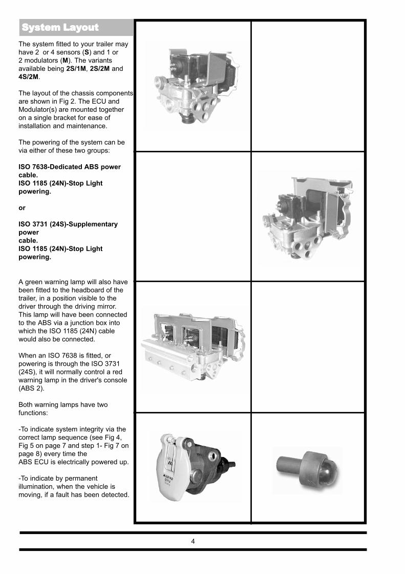
The system fitted to your trailer mayhave 2 or 4 sensors (S) and 1 or2 modulators (M). The variantsavailable being 2S/1M, 2S/2M and4S/2M.
The layout of the chassis componentsare shown in Fig 2. The ECU andModulator(s) are mounted togetheron a single bracket for ease ofinstallation and maintenance.
The powering of the system can bevia either of these two groups:
ISO 7638-Dedicated ABS powercable.ISO 1185 (24N)-Stop Lightpowering.
or
ISO 3731 (24S)-Supplementarypowercable.ISO 1185 (24N)-Stop Lightpowering.
A green warning lamp will also havebeen fitted to the headboard of thetrailer, in a position visible to thedriver through the driving mirror.This lamp will have been connectedto the ABS via a junction box intowhich the ISO 1185 (24N) cablewould also be connected.
When an ISO 7638 is fitted, orpowering is through the ISO 3731(24S), it will normally control a redwarning lamp in the driver's console(ABS 2).
Both warning lamps have twofunctions:
-To indicate system integrity via thecorrect lamp sequence (see Fig 4,Fig 5 on page 7 and step 1- Fig 7 onpage 8) every time theABS ECU is electrically powered up.
-To indicate by permanentillumination, when the vehicle ismoving, if a fault has been detected.
System LaSystem LaSystem LaSystem LaSystem Layyyyyoutoutoutoutout

ISO 1185(24N)
ISO 7638
ISO 3731(24S)
1A1 2
3
48
9
10
11
5 12
8
7
6 Alternative to 5
MODULAR 1 Upgrade
1B
12
MODULAR 23A
2A1
23
4
75
8
9
10
15
11
ISO 3731(24S)
ISO 7638
ISO 1185(24N)
16
14
13
Fig 2
5
6 Alternative to 5 3B2B
8
13
14
Item Description
1 ABS Label 2 Green Warning lamp
Bulb (24v-5w Double pole) 3 2 core cable 4 Junction box5 ISO 7638 Socket
assembly - PVC 6 ISO 3731 (24S) Cable
assembly - PVC 7 ISO 1185 (24N) Cable
assembly - PVC 8 Sensor assembly 9 ECU and Modulator
assembly 10 Loom assembly 11 Diagnostic Connector 12 Diagnostic Label13 Diagnostic Display Unit14 INFO CENTRE
Item Description
1 ABS Label 2 Green Warning lamp
Bulb (24v-5w Double pole) 3 2 core cable 4 Junction box 5 ISO 7638 Socket
assembly - PUR 6 ISO 3731 (24S) Cable
assembly - PUR 7 ISO 1185 (24N) Cable
assembly - PUR 8 Sensor assembly 9 ECU and Modulator
assembly10 Loom assembly
11 Diagnostic Connector 12 Diagnostic Label13 Diagnostic Display Unit
14 INFO CENTRE15 COLAS
16 PC Interface
ABS Chassis Components ABS Chassis Components ABS Chassis Components ABS Chassis Components ABS Chassis Components
®
� �
�� �

Fig 3
DDU Plug locates inloom assemblyDiagnostic connector
DDU
ALTERNATIVEMain LoomassemblyDiagnosticconnectorChassismounted
Diagnosticconnector
ALTERNATIVE POSITIONS
An important feature of theMODULAR system is that itprovides external diagnostics. Thesystem displays a range of codes,which allow rapid diagnosis of theproblem should one occur.
The diagnostic codes can be readfrom a portable Diagnostic DisplayUnit (DDU) or a fixed DiagnosticUnit (INFO CENTRE).The DDU can be connectedremotely via the loom assemblydiagnostic connector socketmounted in an appropriate positionon the trailer chassis indicated inFig 3.The INFO CENTRE is avehicle mounted displaypermanently connected to the trailerABS ECU. Typical locations of thediagnostic connector are shown inFig 3.
The DDU gives two types ofdisplay:
-Horizontal bars indicate theposition of effective speed sensorswhen the wheels are rotated.
-A two digit display can beinterpreted from the list of codesshown on pages 9, 10 and 11.
The INFO CENTRE provides amulti-digit display of:
-Odometer indicates total, trip,service interval kilometres or milesdefined by the ECU and Tyre scalesetting.
-Fault codes as to the list of codesshown on pages 9, 10 and 11.
-ABS ECU Information - Serialnumber,Product code and Configurationcode.
6
INFO CENTRE
ABSINFO
ABSINFO
System Dia System Dia System Dia System Dia System Diagnosticsgnosticsgnosticsgnosticsgnostics
� �

7
RED warning lamp located onthe driver's console of the towingvehicle is operated from theISO 7638 (or ISO 3731 - 24S)power cable only when the ABSis powered by the ignition switch.Fig 4.
GREEN warning lamp mountedon the headboard of the trailerand is operated from theISO 1185 (24N) connector whenthe ABS is powered only fromthe stop lamp power supply i.e.when the brake pedal isdepressed. Fig 5.
The warning lamp(s) functiondepends on which powersupply is used:
1 Note: If a dedicated power source isavailable to the ABS from the ISO 7638connector, or to the ISO 3731 (24S),then system integrity will be indicatedby the RED cab mountedwarning lamp which becomes theprimary ABS status indicator, theGREEN trailer lamp becomes thesecondary indicator and duplicates theRED cab mounted lamp function whenthe stop lamp circuit is operated. Fig 6.
On power up of the system, the warninglamp(s) must illuminate in the followingsequence in order to show a fault-freesystem:
ON for 2.5 seconds = Bulb OK andsystem self-checking.
OFF for 1 second = Systemself-checkedand preparingto checksensors.
ON until moving = Systemwaiting forvehicle tomove above10 km/h inorder to checkthat thesensors areworking.
OFF = Once thevehicle ismoving above10 km/h andthe lamp(s)goes (go) out,the electronicsystem is fullychecked.
2 During the self-check procedure,the system operates themodulator/s solenoid once.On MODULAR 1 this operationwill be audible as one exhaustof air from the modulator(RED channel).On MODULAR 2 one exhaustof air from each modulator insequence will be audible(BLUE channel then YELLOWchannel).
Once these two checks aremade with correct results, nofurther checks are required.
If the results are not satisfactory,the DDU or INFO Centre shouldbe used to establish thediagnosis.
This information is describedvisually in Fig 7 on page 8.(MODULAR 1 system shownonly)
3
REDLamp
Fig 4
GREENLamp
Fig 5
REDLamp
GREENLamp
Fig 6
WWWWWarararararning Lamp & System Checning Lamp & System Checning Lamp & System Checning Lamp & System Checning Lamp & System Check Prk Prk Prk Prk Procedurocedurocedurocedurocedureeeee
8
STEP
2STEP
3
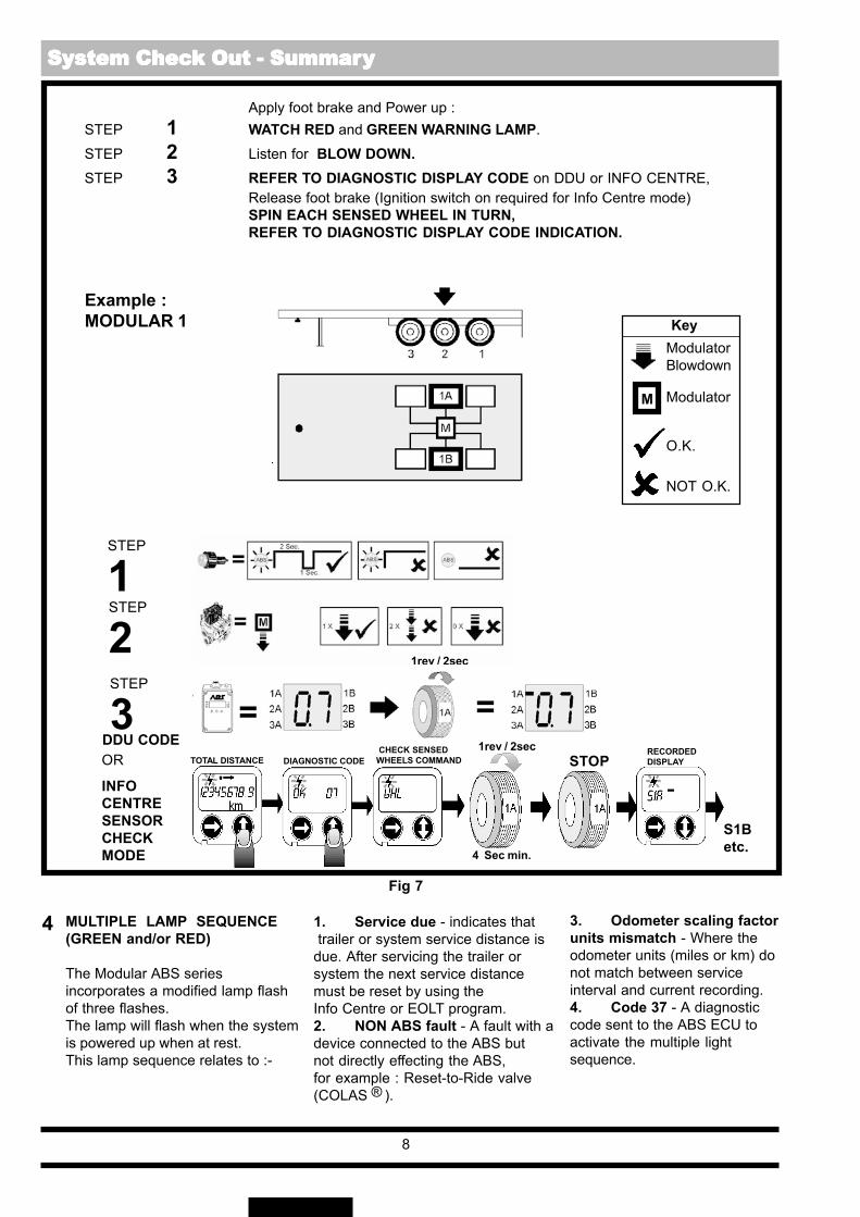
Apply foot brake and Power up :STEP 1 WATCH RED and GREEN WARNING LAMP.STEP 2 Listen for BLOW DOWN.STEP 3 REFER TO DIAGNOSTIC DISPLAY CODE on DDU or INFO CENTRE,
Release foot brake (Ignition switch on required for Info Centre mode)SPIN EACH SENSED WHEEL IN TURN,REFER TO DIAGNOSTIC DISPLAY CODE INDICATION.
INFOCENTRESENSORCHECKMODE
DDU CODEOR
STEP
1
Example :MODULAR 1 Key
ModulatorBlowdown
Modulator
O.K.
NOT O.K.
M
4 MULTIPLE LAMP SEQUENCE(GREEN and/or RED)
The Modular ABS seriesincorporates a modified lamp flashof three flashes.The lamp will flash when the systemis powered up when at rest.This lamp sequence relates to :-
1. Service due - indicates that trailer or system service distance isdue. After servicing the trailer orsystem the next service distancemust be reset by using theInfo Centre or EOLT program.2. NON ABS fault - A fault with adevice connected to the ABS butnot directly effecting the ABS,for example : Reset-to-Ride valve(COLAS ).
3. Odometer scaling factorunits mismatch - Where theodometer units (miles or km) donot match between serviceinterval and current recording.4. Code 37 - A diagnosticcode sent to the ABS ECU toactivate the multiple lightsequence.
4 Sec min.
STOP TOTAL DISTANCE DIAGNOSTIC CODE CHECK SENSEDWHEELS COMMAND
RECORDEDDISPLAY
S1Betc.
Fig 7
1rev / 2sec
System Chec System Chec System Chec System Chec System Check Out - Summark Out - Summark Out - Summark Out - Summark Out - Summaryyyyy
®
1rev / 2sec
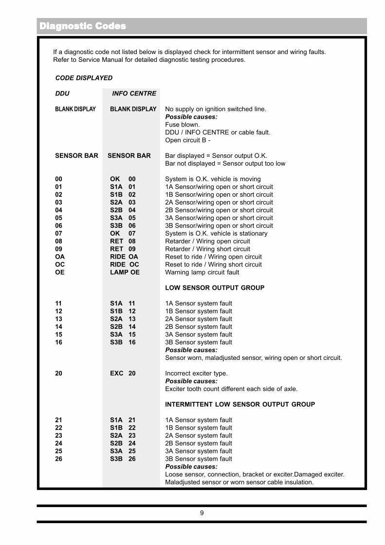
CODE DISPLAYED
DDU INFO CENTRE
BLANK DISPLAY BLANK DISPLAY No supply on ignition switched line.Possible causes:Fuse blown.DDU / INFO CENTRE or cable fault.Open circuit B -
SENSOR BAR SENSOR BAR Bar displayed = Sensor output O.K.Bar not displayed = Sensor output too low
00 OK 00 System is O.K. vehicle is moving01 S1A 01 1A Sensor/wiring open or short circuit02 S1B 02 1B Sensor/wiring open or short circuit03 S2A 03 2A Sensor/wiring open or short circuit04 S2B 04 2B Sensor/wiring open or short circuit05 S3A 05 3A Sensor/wiring open or short circuit06 S3B 06 3B Sensor/wiring open or short circuit07 OK 07 System is O.K. vehicle is stationary08 RET 08 Retarder / Wiring open circuit09 RET 09 Retarder / Wiring short circuitOA RIDE OA Reset to ride / Wiring open circuitOC RIDE OC Reset to ride / Wiring short circuitOE LAMP OE Warning lamp circuit fault
LOW SENSOR OUTPUT GROUP
11 S1A 11 1A Sensor system fault12 S1B 12 1B Sensor system fault13 S2A 13 2A Sensor system fault14 S2B 14 2B Sensor system fault15 S3A 15 3A Sensor system fault16 S3B 16 3B Sensor system fault
Possible causes:Sensor worn, maladjusted sensor, wiring open or short circuit.
20 EXC 20 Incorrect exciter type.Possible causes:Exciter tooth count different each side of axle.
INTERMITTENT LOW SENSOR OUTPUT GROUP
21 S1A 21 1A Sensor system fault22 S1B 22 1B Sensor system fault23 S2A 23 2A Sensor system fault24 S2B 24 2B Sensor system fault25 S3A 25 3A Sensor system fault26 S3B 26 3B Sensor system fault
Possible causes:Loose sensor, connection, bracket or exciter.Damaged exciter.Maladjusted sensor or worn sensor cable insulation.
If a diagnostic code not listed below is displayed check for intermittent sensor and wiring faults.Refer to Service Manual for detailed diagnostic testing procedures.
9
Dia Dia Dia Dia Diagnostic Codesgnostic Codesgnostic Codesgnostic Codesgnostic Codes

CODE DISPLAYED
DDU INFO CENTRE
37 EXT 37 An diagnostic code sent to the ABS ECU to activate themultiple light sequence.
ONE WHEEL WITH SLOW RECOVERY GROUP
40 XSEn 40 Sensor wiring crossed across an axle41 SLW 41 Slow recovery of one wheel of red channel42 SLW 42 Slow recovery of one wheel of blue channel43 SLW 43 Slow recovery of one wheel of yellow channel
Possible causes:Slow brake release, foundation brake mechanical faults, drybearings, broken spring, restricted pipingCheck for kinks and blockages etc.Incorrect piping, WiringModulator fault
OPEN CIRCUIT MODULATOR SOLENOID ORSOLENOID WIRING GROUP
61 RDHd61 Hold solenoid circuit fault, red channel62 BUHd62 Hold solenoid circuit fault, blue channel63 YEHd 63 Hold solenoid circuit fault, yellow channel67 RDDu67 Dump solenoid circuit fault, red channel68 BUDu68 Dump solenoid circuit fault, blue channel69 YEDu 69 Dump solenoid circuit fault, yellow channel
SHORT CIRCUIT ACROSS MODULATOR SOLENOID ORSOLENOID WIRING GROUP
71 RDHd71 Hold solenoid circuit fault, red channel72 BUHd72 Hold solenoid circuit fault, blue channel73 YEHd 73 Hold solenoid circuit fault, yellow channel77 RDDu77 Dump solenoid circuit fault, red channel78 BUDu78 Dump solenoid circuit fault, blue channel79 YEDu 79 Dump solenoid circuit fault, yellow channel
MODULATOR SOLENOID WIRING ORSOLENOID SHORT TO B+ GROUP
80 SOL 80 Poor insulation in the modulator solenoid or wiring fault81 RDHd81 Hold solenoid circuit fault, red channel.82 BUHd82 Hold solenoid circuit fault, blue channel83 YEHd 83 Hold solenoid circuit fault, yellow channel87 RDDu87 Dump solenoid circuit fault, red channel88 BUDu88 Dump solenoid circuit fault, blue channel89 YEDu 89 Dump solenoid circuit fault, yellow channel
SUPPLY VOLTAGE GROUP
90 B+LO 90 Supply voltage at ECU less than 18v when a solenoid is energised91 ISOI 91 Faulty supply from ISO 7638 Pin 1 or fuse blown92 B+HI 92 Supply voltage at the ECU greater than 32v93 ECU 93 Internal ECU fault
10
Dia Dia Dia Dia Diagnostic Codesgnostic Codesgnostic Codesgnostic Codesgnostic Codes

CODE DISPLAYED
DDU INFO CENTRE99 ECU 99 Internal ECU fault
SYSTEM FUNCTION GROUP
A1 AUX A1 Reset to ride heightA2 AUX A2 Retarder
CONFIGURATION CODES
Figures in brackets indicate sensing is disabled when the axleis lifted.
Function Axle Lifted Sensors Used Modulators Used
C0 2S1C C0 2S/1M 1A, 1B RedC1 2S2C C1 2S/2M 2A, 2B Blue, YellowC2 4S2C C2 4S/2M 2A, 2B, 3A, 3B Blue, YellowC3 4S2C C3 4S/2M 2 or 3 2A, 2B, (3A), (3B) Blue, Yellow
SUNDRY ADDITIONAL CODES
CA CLR CA Erase stored faultCC CLR CC Clear ConfigurationCF CF Sensors and Solenoid not connected
Alternating with code 90 (incomplete solenoid function)LO or HI COM FAIL Communication failure between ECU, INFO CENTRE or DDU
open or short circuit wiring
Note: If a code is displayed and after following recommended procedure, as detailed in the ServiceManual, no fault is found, the ABS ECU should be replaced.
11
Dia Dia Dia Dia Diagnostic Codesgnostic Codesgnostic Codesgnostic Codesgnostic Codes

KEY: Colour code
W= WhiteBK= BlackRD= RedYE= YellowBN= BrownPU= Purple
WYE
A B C
ISO 1185 24N
ISO 7638
Fig 8
12
Fig 9
RDBK
BN
PURDYEBKW
W
RD
W
RD
BK
ECU
ECU
ISO 3731 24S
ISO 1185 24N
A = Fuse position (PIN 1 Assembly)B = Fused ISO7638
(PIN positions on interface (9-way) connector are numbered)C = Un-Fused ISO7638
(PIN positions on interface (9-way) connector are colour coded)D = 1m Max. (Applies to ISO3731 - 24S and ISO1185 - 24N,
Headboard to Junction box)
9-way connector (5 positions used) for ISO7638 and ISO3731 (24S).4-way connector (3 positions used) for ISO1185 (24N).
Alt.
2
1
3
76453
D
BKYE
123 4 5
4
1
W
RD
W
RD
BK
YEBK
D
BK
W/BK BN
BN/BK
BK
RD
YEYE
W
RD
12
6
4
12
1
3
P P P P Pooooowwwwwer Suppler Suppler Suppler Suppler Supplyyyyy WWWWWiring - MODULAR 1 Upgiring - MODULAR 1 Upgiring - MODULAR 1 Upgiring - MODULAR 1 Upgiring - MODULAR 1 Upgrrrrradeadeadeadeade

Colour code
W= WhiteBK= BlackRD= RedYE= YellowBN= BrownPU= Purple
RD
W
A B C
ISO 1185 24N
ISO 7638
KEY:
Fig 10
13
ECU
W
RD
BK
W
RD
BKBN
ED
BKYE
ECU
YEBK
D E
BNBK
W
RD
BK
W
RD
BK
BN/BK
W/BKYE
RD
ISO 3731 24S
ISO 1185 24N
Fig 11
A = Fuse position (PIN 1 Assembly)B = Fused ISO7638
(PIN positions on interface (9-way) connector are numbered)C = Un-Fused ISO7638
(PIN positions on interface (9-way) connector are colour coded)D = 1m Max. (Applies to ISO3731 - 24S and ISO1185 - 24N,
Headboard to Junction box)E = Suspension Controller (COLAS )
9-way connector (5 positions used) for ISO7638 and ISO3731 (24S).4-way connector (3 positions used) for ISO1185 (24N).
Alt.
7
6
6
7
17
16
26BN
354
3
1
2
RD
BK
3
1
2
123 54
1
4
YEBK
BN
RDYEBKW
PU
W YE12
6
1
4
2728
2728
P P P P Pooooowwwwwer Suppler Suppler Suppler Suppler Supplyyyyy WWWWWiring - MODULAR 1 Plus & Modular 2iring - MODULAR 1 Plus & Modular 2iring - MODULAR 1 Plus & Modular 2iring - MODULAR 1 Plus & Modular 2iring - MODULAR 1 Plus & Modular 2
®
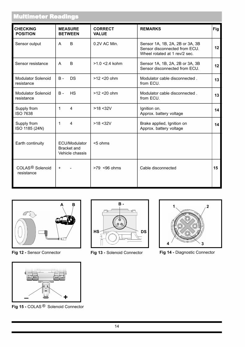
CHECKING MEASURE CORRECT REMARKS Fig POSITION BETWEEN VALUE
Sensor output A B 0.2V AC Min. Sensor 1A, 1B, 2A, 2B or 3A, 3BSensor disconnected from ECU.Wheel rotated at 1 rev/2 sec.
Sensor resistance A B >1.0 <2.4 kohm Sensor 1A, 1B, 2A, 2B or 3A, 3BSensor disconnected from ECU.
Modulator Solenoid B - DS >12 <20 ohm Modulator cable disconnected . resistance from ECU.
Modulator Solenoid B - HS >12 <20 ohm Modulator cable disconnected . resistance from ECU.
Supply from 1 4 >18 <32V Ignition on. ISO 7638 Approx. battery voltage
Supply from 1 4 >18 <32V Brake applied, Ignition on ISO 1185 (24N) Approx. battery voltage
Earth continuity ECU/Modulator <5 ohmsBracket andVehicle chassis
COLAS Solenoid + - >79 <96 ohms Cable disconnected 15 resistance
12
12
13
13
14
14
14
BA B - 1
3
Fig 14 - Diagnostic ConnectorFig 13 - Solenoid ConnectorFig 12 - Sensor Connector
HS DS
Fig 15 - COLAS Solenoid Connector
+_
4
2
Multimeter R Multimeter R Multimeter R Multimeter R Multimeter Readingseadingseadingseadingseadings
®
®
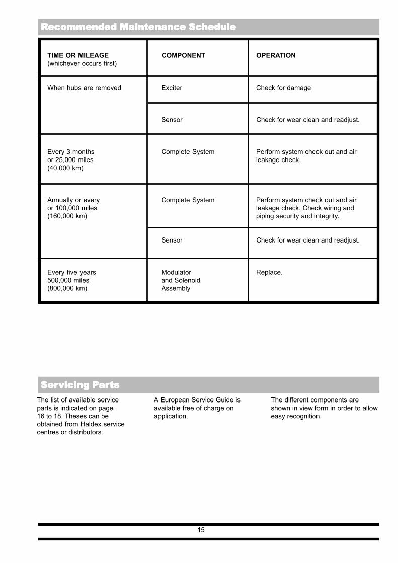
TIME OR MILEAGE COMPONENT OPERATION(whichever occurs first)
When hubs are removed Exciter Check for damage
Sensor Check for wear clean and readjust.
Every 3 months Complete System Perform system check out and airor 25,000 miles leakage check.(40,000 km)
Annually or every Complete System Perform system check out and airor 100,000 miles leakage check. Check wiring and(160,000 km) piping security and integrity.
Sensor Check for wear clean and readjust.
Every five years Modulator Replace.500,000 miles and Solenoid(800,000 km) Assembly
15
The list of available serviceparts is indicated on page16 to 18. Theses can beobtained from Haldex servicecentres or distributors.
A European Service Guide isavailable free of charge onapplication.
The different components areshown in view form in order to alloweasy recognition.
R R R R Recommended Maintenance Scecommended Maintenance Scecommended Maintenance Scecommended Maintenance Scecommended Maintenance Schedulehedulehedulehedulehedule
Ser Ser Ser Ser Servicing Pvicing Pvicing Pvicing Pvicing Pararararartststststs
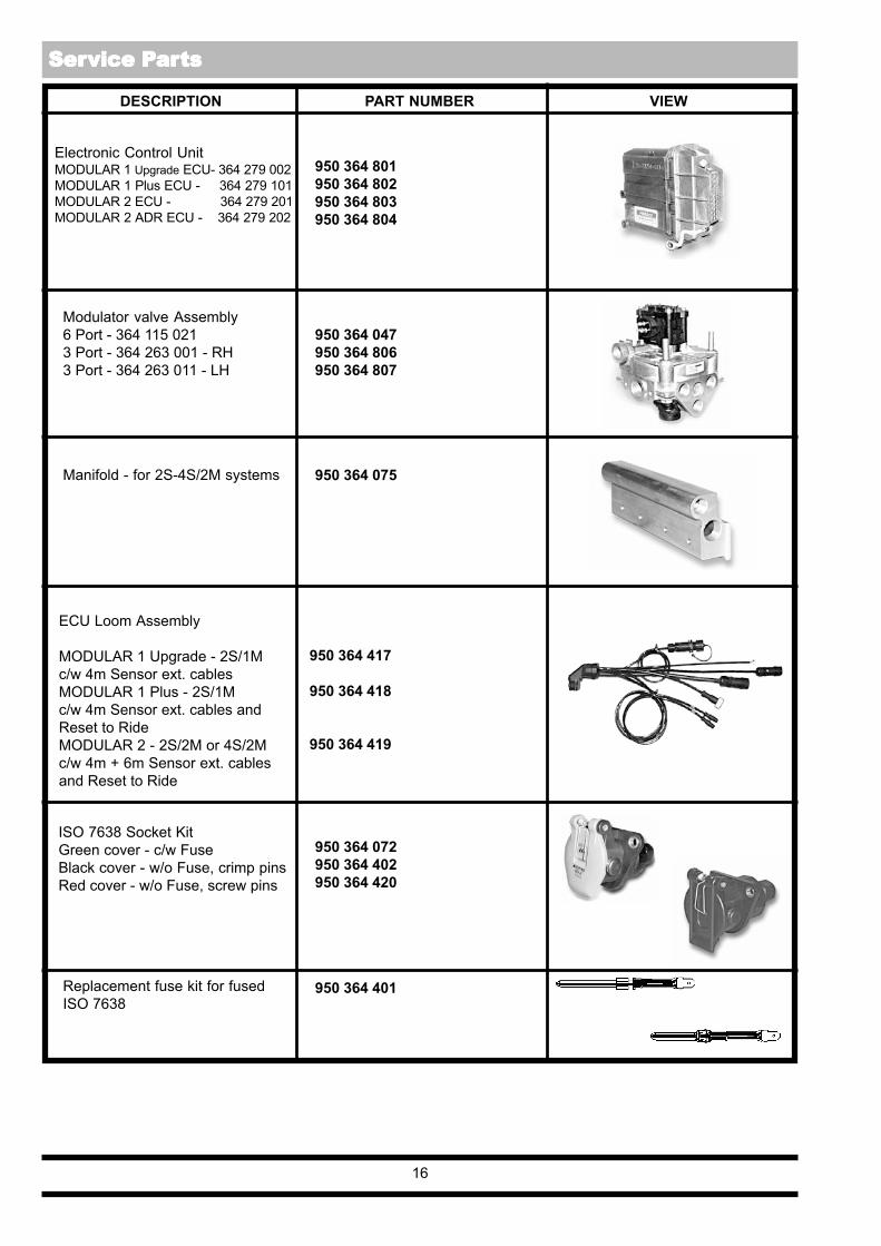
DESCRIPTION PART NUMBER VIEW
Electronic Control UnitMODULAR 1 Upgrade ECU- 364 279 002MODULAR 1 Plus ECU - 364 279 101MODULAR 2 ECU - 364 279 201MODULAR 2 ADR ECU - 364 279 202
950 364 801950 364 802950 364 803950 364 804
Modulator valve Assembly6 Port - 364 115 0213 Port - 364 263 001 - RH3 Port - 364 263 011 - LH
950 364 047950 364 806950 364 807
950 364 072950 364 402950 364 420
Replacement fuse kit for fusedISO 7638
950 364 401
16
950 364 075Manifold - for 2S-4S/2M systems
ECU Loom Assembly
MODULAR 1 Upgrade - 2S/1Mc/w 4m Sensor ext. cablesMODULAR 1 Plus - 2S/1Mc/w 4m Sensor ext. cables andReset to RideMODULAR 2 - 2S/2M or 4S/2Mc/w 4m + 6m Sensor ext. cablesand Reset to Ride
950 364 417
950 364 418
950 364 419
ISO 7638 Socket KitGreen cover - c/w FuseBlack cover - w/o Fuse, crimp pinsRed cover - w/o Fuse, screw pins
Ser Ser Ser Ser Service Pvice Pvice Pvice Pvice Pararararartststststs

DESCRIPTION PART NUMBER VIEW
17
ISO 7638 Socket and cable Assy.Fused - L = 12m - PVCUn-fused - L = 12m - PUR
950 364 421950 364 422
Diagnostic Connector Label 028 5189 09
950 364 702ABS Label
950 364 711Bulb - (24v - 5w) Double pole
950 364 710Green Warning Lamp
ISO 3731 (24S) Cable Assembly(All systems)L = 12m - PVCL = 12m - PUR
950 364 427950 364 428
ISO 1185 (24N) Cable AssemblyFor MODULAR 1 Upgrade and PlusL = 12m - PVCFor MODULAR 2L = 12m - PUR
950 364 425
950 364 426
ISO 7638 Socket / cable +separate interface connectorFused - L = 12m - PVCUn-fused - L = 12m - PUR
950 364 423950 364 424
ISO 7638 Plug and cable Assy.L = 12m - PVC 950 364 429
+
L
Ser Ser Ser Ser Service Pvice Pvice Pvice Pvice Pararararartststststs

DESCRIPTION PART NUMBER VIEW
Sensor Kit - Angled(inc. retaining clip)Sensor Kit - Straight(inc. retaining clip)
ExciterROR TM 100 Tooth
80 ToothROR TE 100 ToothBPW-9T 100 ToothBPW-10T 100 Tooth
950 364 503
950 364 506
018 5003 09018 5004 09018 5005 09950 364 606950 364 607
18
Diagnostic Display Unit (DDU)c/w case and guide
2m Cable only24m Cable only
Case
905 027 001
003 8467 09003 8433 09
042 5074 09
INFO CentreL = 1.2m CableL = 0.4m CableL = 1.2m Cable - ADR VersionL = 0.4m Cable - ADR Version
364 317 001364 317 011364 385 001364 385 011
Vehicle Data System Kit(Interface Pod and Software)c/w Instruction Manualw/o Instruction Manual
'End-of-Line' Test Kit(Interface Pod and Software)c/w Instruction Manualw/o Instruction Manual
950 364 812950 364 814
950 364 813950 364 815
Sensor extension cable repair kit(6m cable)
950 364 507
L
Ser Ser Ser Ser Service Pvice Pvice Pvice Pvice Pararararartststststs

19
User User User User Users Notess Notess Notess Notess Notes

AustriaHaldex Wien Ges.m.b.HViennaTel: + 43 865 16 40Fax: + 43 865 16 4027e-mail: [email protected]
BelgiumHaldex N.V./S.A.Zaventem (Brussels)Tel: + 32 2725 3707Fax: + 32 2752 4099e-mail : [email protected]
BrazilHaldex do BrazilSão PauloTel: + 55 11 531 4999Fax: + 55 11 531 9515e-mail: [email protected]
ChinaHaldex International Trading Co. Ltd.ShanghaiTel: + 86 21 6289 4469Fax: + 86 21 6279 0554e-mail : [email protected]
FranceHaldex Europe S.A.Weyersheim (Strasbourg)Tel: + 333 88 68 22 00Fax: + 333 88 68 22 09e-mail : [email protected]
GermanyHaldex Brake Products G.m.b.HDenkendorf (Stuttgart)Tel: + 49 711 93 49 17 0Fax: + 49 711 93 49 17 40e-mail : [email protected]
Haldex Brake Products G.m.b.HHeidelbergTel: + 49 6221 70 30Fax: + 49 6221 70 34 00e-mail : [email protected]
Innovative Vehicle Technology
For further information:Great BritainHaldex Ltd.Newton AycliffeTel: + 44 1 325 310 110Fax: + 44 1 325 311 834e-mail : [email protected]
Haldex Brake Products Ltd.RedditchTel: + 44 1527 499 499Fax: + 44 1527 499 500e-mail : [email protected]
PolandHaldex Sp z o.o.PraszkaTel: + 48 34 350 11 00Fax: + 48 34 350 11 11e-mail : [email protected]
South KoreaHaldex Korea Ltd.SeoulTel: + 82 2 2636 7545Fax: + 82 2 2636 7548e-mail : [email protected]
SpainHaldex España S.A.Parets del Valles (Barcelona)Tel: + 34 93 573 1030Fax: + 34 93 573 0728e-mail : [email protected]
SwedenHaldex Brake Products ABLandskronaTel: + 46 418 47 6000Fax: + 46 418 47 6001e-mail : [email protected]
USAHaldex Brake Products Corp.Kansas CityTel: + 1 816 891 2470Fax: + 1 816 891 9447e-mail : [email protected]
The Haldex Group is a global supplier of proprietaryproducts for trucks, cars and industrial vehicles, withspecial emphasis on performance and safety.TheGroup is organized in Divisions which focus ontheir respective product niche:
Haldex Brake Systems supplies ABSand brake components for heavy vehicle air brakes.
Haldex Barnes Hydraulics supplies gear pumpsandhydraulic systems for power steering and liftingfunctions on industrial vehicles and trucks.
Haldex Garphyttan Wire supplies specially steel-alloyed wire products mainly for applications incombustion engines.
Haldex Traction Systems supplies 4WD systems forcars and trucks.
Sales companies are established in Europe, North andSouthAmerica and Asia. Production takes place in 9factories in USA, 9 factories in Europe and 1 jointventure in India.
The Haldex Group is listed on the Stockholm StockExchange.
Company VisionWe use our demonstratedcompetence to provide innovativecomponents, systems and service fortrucks, trailers and buses, that lowerlife cycle costs and improve vehiclesafety. Haldex wants to become thefirst choice business partner ofcommercial vehicle manufacturesworld wide in the areas of braking andsuspension control systems with specialemphasis on heavy commercial vehicles.
Total SupportA uniquely wide range of services isavailable from Haldex. These includeexpert consultancy for braking andsuspension development, brakecalculations, type approvals andapplication engineering.The aim is accurate specification formanufactures and low cost of ownership for the operator.Full aftermarket support includes aWorldwide parts distribution andservice network, on-line technicaladvice, field visits and installation/maintenance training held on-site orat Haldex facilities.
Research andDevelopmentContinual, heavy investment inResearch and Development is carriedout in response to ever increasingcommercial, legislative,environmental, performance andtechnological demands.
Quality andProductionStandardsThe very latest production technologyensures the very highest qualitystandards. All production sites areISO 9001 approved.
Related Documents