modul mikroprosessor dan interface
Nov 08, 2014
modul mikroprosessor dan interface
Welcome message from author
This document is posted to help you gain knowledge. Please leave a comment to let me know what you think about it! Share it to your friends and learn new things together.
Transcript

2
I would like to thank to the following people for their support during theproject development:
• Andre Cunha (Brazil) for review of this document
• Kara Blackowiak (USA) for certain code reviews
• Kostya V. Ivanov (Russia) for bug �xes in the simulator engine.
• Shakthi Kannan (India) for adding this software to the FEL projectand for a few patches.
• Miroslav Hradílek (EU) for bug reports and suggestions
• Fabricio Alcalde (Argentina) for suggestions and bug reports.
• Francisco Albani (Argentina) for suggestions and a few bug reports.
3
Contents
Preface 5Goals of the project . . . . . . . . . . . . . . . . . . . . . . . . . . . 5Requirements . . . . . . . . . . . . . . . . . . . . . . . . . . . . . . 6Intended Audience . . . . . . . . . . . . . . . . . . . . . . . . . . . 7
1 Brief introduction 91.1 Main components of MCU 8051 IDE . . . . . . . . . . . . . . 91.2 What is MCS-51 . . . . . . . . . . . . . . . . . . . . . . . . . 121.3 What is the Assembly language . . . . . . . . . . . . . . . . . 12
2 Quick start 152.1 Demonstration project . . . . . . . . . . . . . . . . . . . . . . 152.2 Your �rst project in MCU 8051 IDE . . . . . . . . . . . . . . 16
3 Detailed introduction to GUI 173.1 Source code editor . . . . . . . . . . . . . . . . . . . . . . . . 17
3.1.1 Syntax highlight and validation . . . . . . . . . . . . . 173.1.2 Spell checking . . . . . . . . . . . . . . . . . . . . . . . 173.1.3 Auto-completion . . . . . . . . . . . . . . . . . . . . . 183.1.4 Editor command line . . . . . . . . . . . . . . . . . . . 18
3.2 Bottom panel . . . . . . . . . . . . . . . . . . . . . . . . . . . 203.2.1 Main panel of the MCU simulator . . . . . . . . . . . . 203.2.2 C variables . . . . . . . . . . . . . . . . . . . . . . . . 203.2.3 Graph showing voltage levels . . . . . . . . . . . . . . . 213.2.4 Messages panel . . . . . . . . . . . . . . . . . . . . . . 213.2.5 Notes . . . . . . . . . . . . . . . . . . . . . . . . . . . 223.2.6 Calculator . . . . . . . . . . . . . . . . . . . . . . . . . 223.2.7 Find in �les . . . . . . . . . . . . . . . . . . . . . . . . 233.2.8 Terminal emulator . . . . . . . . . . . . . . . . . . . . 23
3.3 Left panel . . . . . . . . . . . . . . . . . . . . . . . . . . . . . 243.3.1 List of opened �les . . . . . . . . . . . . . . . . . . . . 24
4 CONTENTS
3.3.2 List of project �les . . . . . . . . . . . . . . . . . . . . 243.3.3 SFR watches . . . . . . . . . . . . . . . . . . . . . . . 243.3.4 File system browser . . . . . . . . . . . . . . . . . . . . 24
3.4 Right panel . . . . . . . . . . . . . . . . . . . . . . . . . . . . 243.4.1 List of bookmarks . . . . . . . . . . . . . . . . . . . . . 243.4.2 List of breakpoints . . . . . . . . . . . . . . . . . . . . 253.4.3 Instruction details . . . . . . . . . . . . . . . . . . . . 253.4.4 Data register watches . . . . . . . . . . . . . . . . . . . 253.4.5 Subprograms call monitor . . . . . . . . . . . . . . . . 263.4.6 List of symbols . . . . . . . . . . . . . . . . . . . . . . 263.4.7 HW plug-ins manager . . . . . . . . . . . . . . . . . . 26
3.5 Other tools . . . . . . . . . . . . . . . . . . . . . . . . . . . . 273.5.1 SFR map . . . . . . . . . . . . . . . . . . . . . . . . . 273.5.2 Map of bit addressable area . . . . . . . . . . . . . . . 273.5.3 Stack monitor . . . . . . . . . . . . . . . . . . . . . . . 273.5.4 Symbol viewer . . . . . . . . . . . . . . . . . . . . . . . 283.5.5 ASCII chart . . . . . . . . . . . . . . . . . . . . . . . . 293.5.6 8051 Instruction Table . . . . . . . . . . . . . . . . . . 293.5.7 8-segment editor . . . . . . . . . . . . . . . . . . . . . 293.5.8 Stopwatch . . . . . . . . . . . . . . . . . . . . . . . . . 293.5.9 Scribble notepad . . . . . . . . . . . . . . . . . . . . . 293.5.10 Base converter . . . . . . . . . . . . . . . . . . . . . . 303.5.11 RS-232 debugger . . . . . . . . . . . . . . . . . . . . . 303.5.12 Hexadecimal editors . . . . . . . . . . . . . . . . . . . 313.5.13 Hibernation of simulated program . . . . . . . . . . . . 323.5.14 Interrupt monitor . . . . . . . . . . . . . . . . . . . . . 323.5.15 Conversions between *.hex, *.bin and *.adf �les . . . . 333.5.16 Normalization of source code indentation . . . . . . . . 333.5.17 Change letter case . . . . . . . . . . . . . . . . . . . . 333.5.18 User de�ned commands . . . . . . . . . . . . . . . . . 343.5.19 Clean-up project folder . . . . . . . . . . . . . . . . . . 353.5.20 File statistic . . . . . . . . . . . . . . . . . . . . . . . . 35
3.6 Con�guration dialogues . . . . . . . . . . . . . . . . . . . . . . 35
4 Build-in macro-assembler 394.1 Statements . . . . . . . . . . . . . . . . . . . . . . . . . . . . . 394.2 Symbols . . . . . . . . . . . . . . . . . . . . . . . . . . . . . . 394.3 Constants . . . . . . . . . . . . . . . . . . . . . . . . . . . . . 404.4 Expressions . . . . . . . . . . . . . . . . . . . . . . . . . . . . 414.5 The instruction set processing . . . . . . . . . . . . . . . . . . 424.6 Assembler directives . . . . . . . . . . . . . . . . . . . . . . . 43

CONTENTS 5
4.7 Assembler Controls . . . . . . . . . . . . . . . . . . . . . . . . 474.8 Prede�ned Symbols . . . . . . . . . . . . . . . . . . . . . . . . 494.9 Segment type . . . . . . . . . . . . . . . . . . . . . . . . . . . 514.10 Conditional Assembly . . . . . . . . . . . . . . . . . . . . . . . 534.11 Macro Processing . . . . . . . . . . . . . . . . . . . . . . . . . 544.12 Reserved keywords . . . . . . . . . . . . . . . . . . . . . . . . 584.13 Compatibility with ASEM-51 . . . . . . . . . . . . . . . . . . 594.14 List File Format . . . . . . . . . . . . . . . . . . . . . . . . . . 604.15 Speci�cation of Intel R©8 HEX Format . . . . . . . . . . . . . . 62
5 Disassembler 63
6 MCU simulator 656.1 Short introduction . . . . . . . . . . . . . . . . . . . . . . . . 656.2 Modes of simulation . . . . . . . . . . . . . . . . . . . . . . . 656.3 Waring conditions . . . . . . . . . . . . . . . . . . . . . . . . . 666.4 Limitations . . . . . . . . . . . . . . . . . . . . . . . . . . . . 666.5 Virtual hardware . . . . . . . . . . . . . . . . . . . . . . . . . 67
6.5.1 DS1620 temperature sensor . . . . . . . . . . . . . . . 676.5.2 File interface . . . . . . . . . . . . . . . . . . . . . . . 676.5.3 LED Panel . . . . . . . . . . . . . . . . . . . . . . . . 686.5.4 Single LED Display . . . . . . . . . . . . . . . . . . . . 686.5.5 Multiplexed LED Display . . . . . . . . . . . . . . . . 686.5.6 LED Matrix . . . . . . . . . . . . . . . . . . . . . . . . 696.5.7 Matrix Keypad . . . . . . . . . . . . . . . . . . . . . . 696.5.8 Simple Keypad . . . . . . . . . . . . . . . . . . . . . . 706.5.9 LCD display controlled by HD44780 . . . . . . . . . . 70
7 Writing hardware tool control plug-ins 717.1 Foreword . . . . . . . . . . . . . . . . . . . . . . . . . . . . . . 717.2 How to write your own plug-in . . . . . . . . . . . . . . . . . . 727.3 Using MCU 8051 IDE API . . . . . . . . . . . . . . . . . . . . 737.4 A basic example . . . . . . . . . . . . . . . . . . . . . . . . . . 747.5 Random remarks . . . . . . . . . . . . . . . . . . . . . . . . . 75
8 Command Line Interface 77
9 Translating the IDE into di�erent languages 79
A License 81

6 CONTENTS
B Regression testing 83B.1 Foreword . . . . . . . . . . . . . . . . . . . . . . . . . . . . . . 83B.2 More about the implementation . . . . . . . . . . . . . . . . . 83
C Project web page and other media 85C.1 O�cial project web page . . . . . . . . . . . . . . . . . . . . . 85C.2 Other media . . . . . . . . . . . . . . . . . . . . . . . . . . . . 86C.3 GIT repository . . . . . . . . . . . . . . . . . . . . . . . . . . 86
D 8051 Instructions in numerical Order 87
E 8051 Instructions in alphabetical order 93
F List of supported micro-controllers 99F.0.1 Intel R© . . . . . . . . . . . . . . . . . . . . . . . . . . . 99F.0.2 Atmel R© . . . . . . . . . . . . . . . . . . . . . . . . . . 99
G Change log 101
7
Preface
Goals of the project
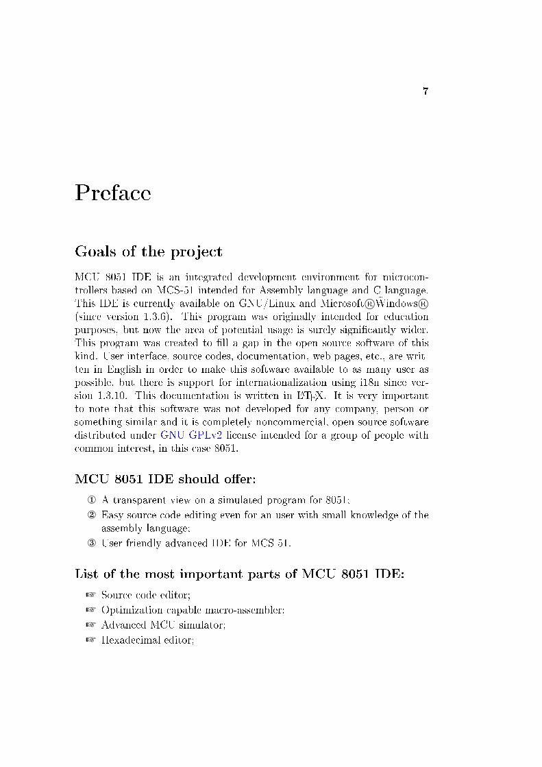
MCU 8051 IDE is an integrated development environment for microcon-trollers based on MCS-51 intended for Assembly language and C language.This IDE is currently available on GNU/Linux and Microsoft R© �Windows R©(since version 1.3.6). This program was originally intended for educationpurposes, but now the area of potential usage is surely signi�cantly wider.This program was created to �ll a gap in the open source software of thiskind. User interface, source codes, documentation, web pages, etc., are writ-ten in English in order to make this software available to as many user aspossible, but there is support for internationalization using i18n since ver-sion 1.3.10. This documentation is written in LATEX. It is very importantto note that this software was not developed for any company, person orsomething similar and it is completely noncommercial, open source softwaredistributed under GNU GPLv2 license intended for a group of people withcommon interest, in this case 8051.
MCU 8051 IDE should o�er:
¬ A transparent view on a simulated program for 8051;
Easy source code editing even for an user with small knowledge of theassembly language;
® User friendly advanced IDE for MCS-51.
List of the most important parts of MCU 8051 IDE:
+ Source code editor;
+ Optimization capable macro-assembler;
+ Advanced MCU simulator;
+ Hexadecimal editor;
8 CONTENTS
+ Interface for hardware tool control plug-ins;
+ Scienti�c calculator and special calculator optimized for 8051.
Requirements
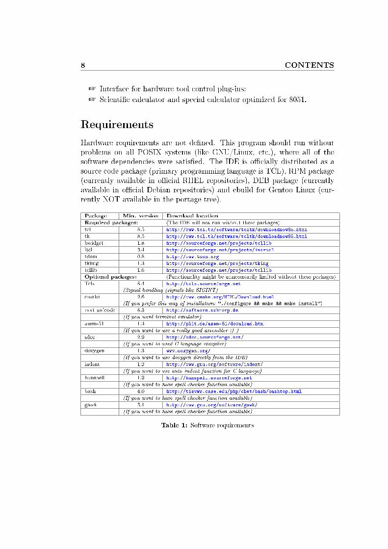
Hardware requirements are not de�ned. This program should run withoutproblems on all POSIX systems (like GNU/Linux, etc.), where all of thesoftware dependencies were satis�ed. The IDE is o�cially distributed as asource code package (primary programming language is TCL), RPM package(currently available in o�cial RHEL repositories), DEB package (currentlyavailable in o�cial Debian repositories) and ebuild for Gentoo Linux (cur-rently NOT available in the portage tree).
Package Min. version Download location
Required packages: (The IDE will not run without these packages)
tcl 8.5 http://www.tcl.tk/software/tcltk/downloadnow85.html
tk 8.5 http://www.tcl.tk/software/tcltk/downloadnow85.html
bwidget 1.8 http://sourceforge.net/projects/tcllib
itcl 3.4 http://sourceforge.net/projects/incrtcl
tdom 0.8 http://www.tdom.org
tkimg 1.3 http://sourceforge.net/projects/tkimg
tcllib 1.6 http://sourceforge.net/projects/tcllib
Optional packages: (Functionality might be unnecessarily limited without these packages)
Tclx 8.4 http://tclx.sourceforge.net
(Signal handling (signals like SIGINT)
cmake 2.6 http://www.cmake.org/HTML/Download.html
(If you prefer this way of installation: �./configure && make && make install�)
rxvt-unicode 8.3 http://software.schmorp.de
(If you want terminal emulator)
asem-51 1.3 http://plit.de/asem-51/download.htm
(If you want to use a really good assembler :) )
sdcc 2.9 http://sdcc.sourceforge.net/
(If you want to used C language compiler)
doxygen 1.3 www.doxygen.org/
(If you want to use doxygen directly from the IDE)
indent 1.2 http://www.gnu.org/software/indent/
(If you want to use auto-indent function for C language)
hunspell 1.2 http://hunspell.sourceforge.net
(If you want to have spell checker function available)
bash 4.0 http://tiswww.case.edu/php/chet/bash/bashtop.html
(If you want to have spell checker function available)
gawk 3.1 http://www.gnu.org/software/gawk/
(If you want to have spell checker function available)
Table 1: Software requirements
CONTENTS 9
Intended Audience
This manual is intended for any individual, regardless of his or her experiencewith assembler, C language, MCU 8051 IDE or Linux, but it is assumed herethat the reader is familiar with basic concepts of assembly language program-ming and with 8051 processor architecture. Advanced users are not likely toread this manual, but all suggestions on documentation will be considered.If you would like to contribute to this project or the documentation, pleaseconsult the project web page.
Thanks for your cooperation which helps to make this software better.

10 CONTENTS
11
Chapter 1
Brief introduction
This chapter will provide you with a brief introduction about the main com-ponents that are part of MCU 8051 IDE. The purpose of this chapter is tocontextualize you on the sofware, informing about the parts that composesit. The next chapter will cover rapidly the Graphical User Interface, whichwill be described in further details on chapter.
1.1 Main components of MCU 8051 IDE
Editor The code editor is featured with syntax highlighting and validation,auto-completion and spell checking for comments 1, as well as a commandline that speeds up the access to various editor options. It also providesa panel showing line numbers, bookmarks, breakpoints and warnings fromsyntax validator. Editor is capable to export the source code within it asXHTML and LATEX and contains a number of useful tools like automaticindentation, searching and replacement of expressions, copy to clipboard,paste from clipboard, among others.
Assembler The assembler is one of the integral parts of MCU 8051 IDE. Itis a macro assembler with support for dozens of directives and capable of per-forming peephole optimizations. Support for peephole optimizations meansthat the assembler can attempt to optimize the resulting code for higher exe-cution speed and lower size without tempering with its very functionality. Itis important to note that automatic peephole optimization can sometimes beharmful and so it is disabled by default. A macro assembler is a software thatallows the user to de�ne a macro instruction, which consists of a sequence
1Spell checking for comments is available only if you have installed the Hunspell pro-gram. This feature is currently not available on MS R©Windows R©OS.

12 CHAPTER 1. BRIEF INTRODUCTION
of basic instructions, and use it later instead of repeatedly copying and past-ing the set of instructions over and over along the source code. Assemblerbehavior can be con�gured either globally, using the proper con�guration di-alog, or locally in source code, by means of assembler directives and controlsequences (e.g. $TITLE('Some title to show in the code listing')).The assembler is capable of generating four kinds of output code:
+ Object code (machine code) as an hexadecimal �le, with .hex extensionand in Intel R© 8 HEX format;
+ Object code (machine code) as a binary �le, with .bin extension andin format of raw binary data;
+ Code listing, in .lst extension;
+ Code for integrated MCU simulator, in .adf extension.
Simulator The simulator is a software component intended for the simu-lation of the chosen microcontroller in a virtual environment. It allows userto monitor precisely what is happening in the MCU in an exact moment intime, as well as to modify its components, for instance by altering the valueof a register, canceling an interrupt or forcing a subprogram to return. Inthat way it might be possible to ferret out certain �aws in the program be-ing debugged, which would be hard or nearly impossible to �nd and/or �xin other ways. Even though it is better to have ICD (In-Circuit Debugger)or ICE (In-Circuit Emulator) at hand, MCU 8051 IDE in current versiondoes not support neither of them MCU simulator implemented in this IDEsupports dozens of microcontrollers and most of them are treated in slightlydi�erent way allowing to take into account most of the nuances between thesupported MCUs. User can adjust simulator behavior to �t his or her needsby modifying clock frequency, size of connected external code, data memoryand others, or for instance by disabling or enabling certain warnings, whichpops up when the simulated program do something �strange�, like some kindof invalid access into memory or stack over�ow or under�ow. Besides that,it is possible for the user to modify all registers which the MCU deals with,including those which are not accessible by the running program, like theProgram Counter. User have always an overview of all possible, pending andactive interrupts and can temper with them at any time. The simulator alsoallows for altering code memory and all kinds of data memories. The pro-gram being simulated can be at any time "hibernated" into a �le, preferablywith .m5ihib extension, and resumed later from this same �le. Such a �lecontains the entire state of the simulator at the point in which the programwas hibernated.
1.1. MAIN COMPONENTS OF MCU 8051 IDE 13
Project management It is a functionality that allows the IDE to remem-ber certain set of source code �les along with a set of con�guration param-eters. Projects are stored in XML (eXtensible Markup Language) �les withextension .mcu8051ide. These �les are human readable and their preciseformatting is described in their inline DTD (Document Type Declaration).Their encoding is UTF-8 (Unicode Transformation) and as EOL (End OfLine) character they use LF (Line Feed). The reason for that is to make itpossible for the user to implement his or her own tools for manipulating withthem.
Scienti�c calculator MCU 8051 IDE scienti�c calculator is implementedas a simple scienti�c calculator capable of computation in four number sys-tems: hexadecimal, decimal, octal and binary, and with three angle units:radians, degrees and grad. Integral part of the calculator is also a simple toolintended solely for computing preset values for MCU timers.
Special calculator The experience in MCU programming shows that itis very useful to have some tools at hand, capable of performing recurrentboring calculations that spend time to be done by hand. MCU 8051 IDEspecial calculator is intended for performing certain simple specialized calcu-lations related to 8051. For instance, this calculator is capable of generatingassembly language code implementing a wait loop with speci�ed parameters.
Hexadecimal editor This utility is used here for watching and modifyinglarge blocks of raw data in various memory types of the simulated MCU(Code, IDATA, XDATA, EEPROM, etc.). There is also hexadecimal editorintended for editing Intel R© HEX 8 �les. Other hexadecimal editors arespecially designed to �t speci�c needs of the given purpose; for example,there is an hexadecimal editor for viewing and editing code memory, whichdisplays the current position of the program counter in the machine code ofthe simulated program.
Disassembler This tool can translate once assembled code back to sourcecode. It is important to note that it is somewhat improbable that the result-ing source code will look "reasonable" It is due to DB and DW and not �xedinstruction word length on 8051. Nevertheless, such a generated source codemust posses exactly the same functionality when it gets assembled again.Disassembler implemented in this IDE is frankly speaking only a little morethat just a toy. If you want a really capable disassembler, maybe you shouldtry some tool like D52 http://www.8052.com/users/disasm/.

14 CHAPTER 1. BRIEF INTRODUCTION
Notepad In this IDE, it is a simple rich text editor for writing user notesof whatever kind. Originally, it was intended for writing a list of things whichremain to be done in your project.
Command Line Interface (CLI) It is an useful tool that allows theuse of some IDE functions without entering it's GUI. You can get list ofavailable options by typing mcu8051ide -h or mcu8051ide �help to yourterminal emulator. You can, for example, use just the assembler of the IDEor convert an Intel R© HEX 8 �le to a raw binary �le.
1.2 What is MCS-51
Figure 1.1: i8051 micro-architecture
The Intel MCS-51 is a Harvard architecture, singlechip micro-controller (µC) series which was devel-oped by Intel in 1980 for use in embedded systems.Intel's original versions were popular in the 1980sand early 1990s, but has today[update] largely beensuperseded by a vast range of faster and/or func-tionally enhanced 8051-compatible devices manu-factured by more than 20 independent manufac-turers including Atmel, In�neon Technologies (for-merly Siemens AG), Maxim Integrated Products(via its Dallas Semiconductor subsidiary), NXP(formerly Philips Semiconductor), Nuvoton (for-merly Winbond), ST Microelectronics, Silicon Lab-oratories (formerly Cygnal), Texas Instruments and Cypress Semiconductor./This was taken from Wikipedia in 2010/
1.3 What is the Assembly language
An assembly language is a low-level programming language for computers,microprocessors, microcontrollers and other integrated circuits. It imple-ments a symbolic representation of the binary machine codes and other con-stants needed to program a given CPU architecture. Processors based onMSC-51 have compatible instruction set, similar registers and many otherthings are generally very similar among them.
Here is an example of how a piece of 8051 assembly code looks like:

1.3. WHAT IS THE ASSEMBLY LANGUAGE 15
Code 1 An example piece of code written in 8051 assembly languagemain:
if test=2
mov R0, #25h
; Configure EEPROM
orl EECON, #38h
inc R0
endif
X0MI:
anl EECON, #(0FFh - 020h)
movx @R0, A

16 CHAPTER 1. BRIEF INTRODUCTION

17
Chapter 2
Quick start
2.1 Demonstration project
The aim of the demonstration project is to provide an easy way to explorethe IDE without reading long and boring documents like this one. :) Thedemonstration project can be opened from the welcome dialog ( �Main Menu�→ �Help� → � Welcome dialog� → �Open demonstration project�. )Demonstration project should introduce new user into usage of the mostcommon functions of the IDE like assembling the code, running simulatorand so on. Demonstration project cannot be modi�ed by the user in orderto make it �less volatile�.
Figure 2.1: MCU 8051 IDE with the demonstration project opened within it

18 CHAPTER 2. QUICK START
2.2 Your �rst project in MCU 8051 IDE
Figure 2.2: Project creation dialog
At �rst let me explain what the MCU 8051 IDE'sproject really is. It is a set of some �les insome directory, let's call this directory theproject directory. And this along with the�le with extension .mcu8051ide forms theproject. The �le with .mcu8051ide exten-sion de�nes what source code �les belongsto the project and contains additional infor-mation about the project, like who is theproject author or for what exact MCU isthe project intended.
To create you project in you have tospecify the project directory and the MCUtype for which you will develop your code.This is done in project creation dialog. Thisdialog can be accessed from main menu �Main Menu� → �Project� → �New�. After this step you can specify some additional information about theproject in project editing dialog.
Once you have created a new project you can begin to develop you codefrom your chosen processor. When you want to save your code press Ctrl+S,Ctrl+N creates a new �le and an existing �le can be opened by Ctrl+O. Eachopened �le can be added or removed to/from your current project. Ctrl+Bcreates or deletes bookmark and Ctrl+Shift+B creates or deletes breakpoint.Project �les, the �les which are parts of the project, are opened each timeyou open the project. You can have more than one project opened at thetime.
Simulator can be started and shut down by pressing F2 key and assembleror compiler is run when F11 is pressed. Output from assembler or compiler isdisplayed on the bottom panel in tab �Messages�. And main MCU simulatorpanel is also available on the bottom panel in tab �Simulator�.
On the left side you can �nd list of currently opened source code �lesand list of project �les. And on the right side probably most useful toolat the beginning might be �Instruction details�, this tool displays help forinstruction in the code editor on line with cursor. In the right panel you can�nd for example also list of bookmarks and breakpoints.

19
Chapter 3
Detailed introduction to GUI
3.1 Source code editor
3.1.1 Syntax highlight and validation
Figure 3.1: Syn-tax validation con�gu-ration button
The editor is equipped with an implementation of a syn-tax highlighting algorithm based on simpli�ed syntaxanalysis. And that enables a limited on-line syntax val-idation. That means that as the user writes down thecode, editor tries to check it for syntactical correctness.Syntax validator marks �strange looking� lines with ex-clamation mark and tries to underline exact point ofpotential syntax errors. This feature can be disabledas well as syntax highlighting can be disabled. By disabling these featuresyou can make the editor work faster, but it would probably mean only aunnecessary limitation. There are three levels of syntax validation:
• 0: Disabled
• 1: Fast basic validation
• 2: Slow advanced validation
Syntax validation con�guration button react to left and right click with themouse pointer. Right button click decreases the level of validation and theleft button click increases it.
3.1.2 Spell checking
20 CHAPTER 3. DETAILED INTRODUCTION TO GUI
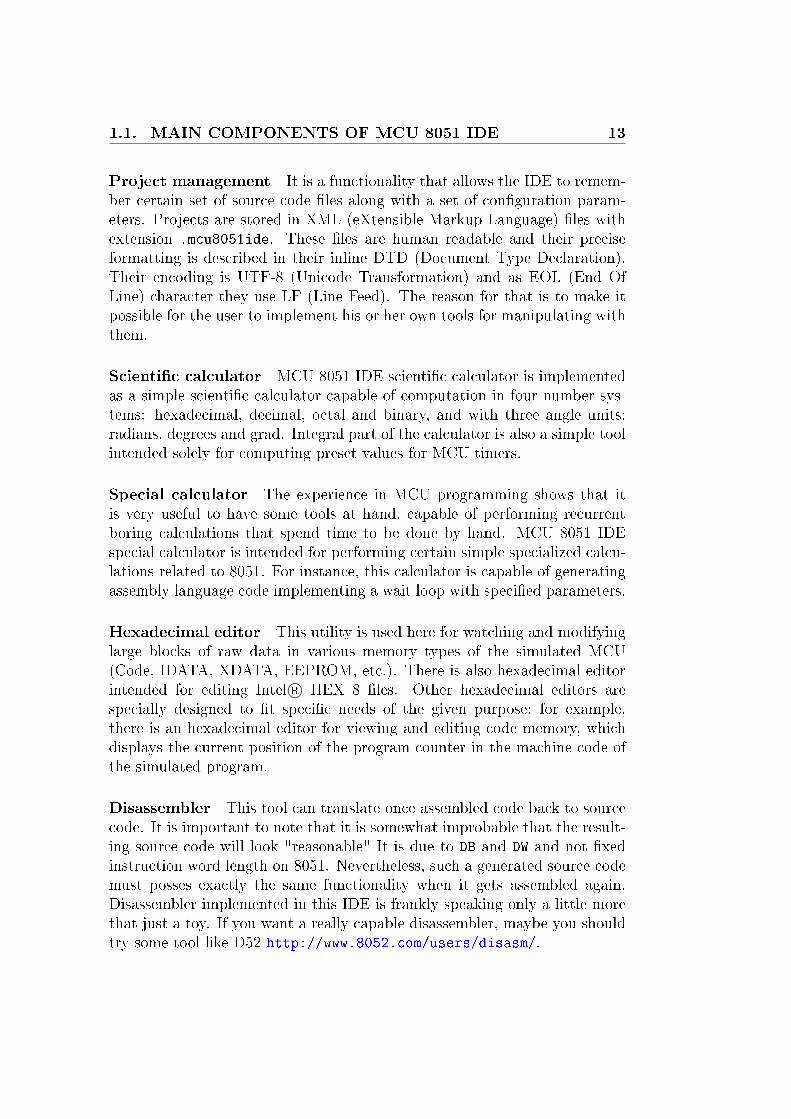
Figure 3.2: Spellchecker con�gurationbutton
There is also con�gurable spell checking function avail-able. It underlines words which are marked by Hun-spell1 as incorrectly spelled. This function applies tocomments in the code or the entire code in case thatthe syntax highlight function has been disabled. Usercan choose from any of Hunspell or Myspell dictionar-ies installed on his or her system. This feature canalso be turned o�. It makes sense that this function is
completely dependent on the Hunspell program, if it is not installed, spellchecking won't work here.
3.1.3 Auto-completion
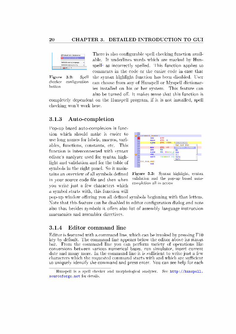
Figure 3.3: Syntax highlight, syntaxvalidation and the pop-up based auto-completion all in action
Pop-up based auto-completion is func-tion which should make it easier touse long names for labels, macros, vari-ables, functions, constants, etc. Thisfunction is interconnected with syntaxeditor's analyzer used for syntax high-light and validation and for the table ofsymbols in the right panel. So it main-tains an overview of all symbols de�nedin your source code �le and then whenyou write just a few characters whicha symbol starts with, this function willpop-up window o�ering you all de�ned symbols beginning with that letters.Note that this feature can be disabled in editor con�guration dialog and notealso that besides symbols it o�ers also list of assembly language instructionmnemonics and assembler directives.
3.1.4 Editor command line
Editor is featured with a command line, which can be invoked by pressing F10key by default. The command line appears below the editor above its statusbar. From the command line you can perform variety of operations likeconversions between various numerical bases, run simulator, insert currentdate and many more. In the command line it is su�cient to write just a fewcharacters which the requested command starts with and which are su�cientto uniquely identify the command and press enter. You can see help for each
1Hunspell is a spell checker and morphological analyzer. See http://hunspell.
sourceforge.net for details.

3.1. SOURCE CODE EDITOR 21
command by running command help list. Command line is featured withits own color highlight, history and auto-completion.
Command Arguments Description
d2h <decimal number> Convert decimal number into hexadecimald2o <decimal number> Convert decimal number into octald2b <decimal number> Convert decimal number into binaryh2d <hexadecimal number> Convert hexadecimal number into decimalh2o <hexadecimal number> Convert hexadecimal number into octalh2b <hexadecimal number> Convert hexadecimal number into binaryo2h <octal number> Convert octal number into hexadecimalo2d <octal number> Convert octal number into decimalo2b <octal number> Convert octal number into binaryb2h <binary number> Convert binary number into hexadecimalb2d <binary number> Convert binary number into decimalb2o <binary number> Convert binary number into octalanimate Animate simulated programassemble Run assemblerauto-indent Automatically indent the edited codebookmark Create or delete bookmark on the current linebreakpoint Create or delete breakpoint on the current linecapitalize Capitalize selected textclear Clear historycomment Comment selectioncopy Copy selectioncustom <command number> Run user commandcut Cut selectiondate <date format> Insert current time and/or dateexit Leave command lineexit-program Exit the IDEfind <string> Find a stringgoto <line number> Go to the speci�ed linehelp <command name> Display help for the speci�ed commandchar <character code> Insert a characterindent Indent selectionkill-line Delete current lineopen <�le name> Open the speci�ed �lepaste Paste text from clipboardredo Take back last undoreload Reload current documentreplace <string> <replacement> Replace a string with another stringrun Run simulator in animation modesave Save the current �leset-icon-border Show/Hide icon borderset-line-numbers Show/Hide line numberssim Engage/Disengage simulatorstep Step simulated programtolower Convert selected text to lowercasetoupper Convert selected text to uppercaseuncomment Comment current lineundo Undo the last text editing operationunindent Decrease indentation level of the current linehibernate [<target �le>] Hibernate simulated programresume [<source �le>] Resume hibernated programswitch-mcu <MCU name> Switch current MCU simulation mode to another MCUset-xcode <size of XCODE mem.> Set size external data memory for simulated MCUset-xdata <size of XDATA mem.> Set size external program memory for simulated MCU
Table 3.1: Available commands

22 CHAPTER 3. DETAILED INTRODUCTION TO GUI
3.2 Bottom panel
3.2.1 Main panel of the MCU simulator
This panel is the main part of the simulator user interface. It shows all MCUregisters along with content of internal data memory. And contains smalltoolbar with 6 buttons: � Start�/� Shutdown�, � Reset�, � Step back�,� Step�, � Step over�, � Animate� and � Run�. All visible registers can bemodi�ed from here and most SFR registers are represented by enumeration ofbits, where each particular bit can be modi�ed separately, green color meanslogical one and red means zero. Each bit has its own tooltip help with shortdescription of its purpose and status bar tip with bit address and bit name.
Figure 3.4: Main panel of the simulator
Figure 3.5: HighlightedSFR register
Figure 3.6: Tool tip helpfor a special function bit
Figure 3.7: Representa-tion of a register value invarious numeric bases
3.2.2 C variables
This panel is a part of simulator user interface that maintains a list of globalstatic variables de�ned in your C language code. Names of variables aredisplayed along with their current values in simulated MCU. If you programis not written in C language then this tool has no purpose for you at all.Otherwise the purpose of this panel is to make it easier to simulate a programfor 8051 written in C language and see what is �really� happening in there.This tool is capable of extracting variable values from multiple registers andthe displaying them as one variable, one value. Alteration of variable valuesis also possible. And search panel in the top right corner of the panel might

3.2. BOTTOM PANEL 23
help you with �nding exact variable which you need to see. But note thatfunctionality of this tool is in fact severely limited, it supports only globalstatic variables, integers and �oats, but variable value modi�cation is allowedonly for integer variables, no �oats.
3.2.3 Graph showing voltage levels
This panel might help you to see what is happening on simulated GPIO2
lines. Resolution and grid can be adjusted to better �t your needs. Thereare three graphs, one for port latches, one for port outputs (without anyvirtual HW) and one for the most realistic GPIO simulation which this IDEcan do.
Figure 3.8: GPIO Graph
3.2.4 Messages panel
This panel displays output from the build-in assembler, external assemblers,C compiler and other external tools used in this IDE, which prints some-thing important to standard output. Output from assemblers and SDCC(C compiler) is parsed to highlight warnings and errors and convert them tohyperlinks pointing to source code if possible. The panel also implementsa tool for searching strings in the displayed text. User can make this toolsvisible by pressing Ctrl+F.
Figure 3.9: Messages panel
2General Purpose Input Output

24 CHAPTER 3. DETAILED INTRODUCTION TO GUI
3.2.5 Notes
This is your personal notes for whatever you want. Originally it was intendedfor writing down a list of things which you need to �nish in your work, sosome sort of a to do list. But it is just a simple rich text editor with separate�le speci�c notepad. User can use it as he or she consider appropriate.
Figure 3.10: Personal notes
3.2.6 Calculator
Calculator is here more or less just for completeness. But you might still�nd it to a real asset to your e�orts. This calculator is capable of performingcommon arithmetical operations, computing trigonometric functions, logi-cal operations, etc. Supported numeral systems are hexadecimal, decimal,octal and binary in both integer and real numbers. Supported angular mea-surement units are degrees, radians and gradians. The calculator is alsoequipped with three memory cells where you can save arbitrary numbers forfuture computations. On the right side there is a simple calculator dedicatedto calculation timers preset values for the speci�ed time, clock frequency, etc.3
Figure 3.11: Calculator
3Essentially the same but much more advanced function has also the special calculator.
3.2. BOTTOM PANEL 25
3.2.7 Find in �les
With this tool you can search all �les in certain directory which namesmatches speci�ed GLOB4 pattern. The search is made for a plain stringor regular expression match. This tool might be very useful when you aredealing with many, possibly large, source code �les and you suddenly want to�nd something speci�c in them. Each line printed in the list of found entriesis a hypertext link which opens the �le mentioned in it in the source codeeditor and navigates the editor to line matching the item. In other words itgenerally the same as well known Unix command �grep�5, but with graphicaluser interface.
3.2.8 Terminal emulator
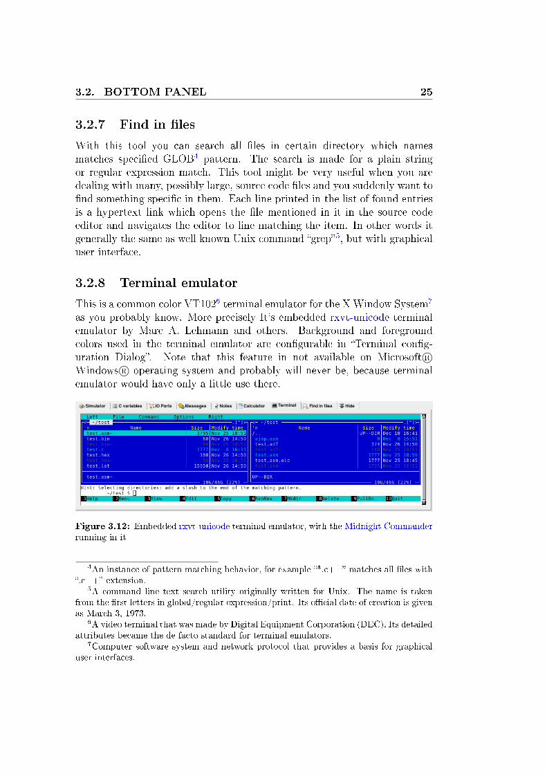
This is a common color VT1026 terminal emulator for the XWindow System7
as you probably know. More precisely It's embedded rxvt-unicode terminalemulator by Marc A. Lehmann and others. Background and foregroundcolors used in the terminal emulator are con�gurable in �Terminal con�g-uration Dialog�. Note that this feature in not available on Microsoft R©Windows R© operating system and probably will never be, because terminalemulator would have only a little use there.
Figure 3.12: Embedded rxvt-unicode terminal emulator, with the Midnight Commanderrunning in it
4An instance of pattern matching behavior, for example �*.c++� matches all �les with�.c++� extension.
5A command line text search utility originally written for Unix. The name is takenfrom the �rst letters in global/regular expression/print. Its o�cial date of creation is givenas March 3, 1973.
6A video terminal that was made by Digital Equipment Corporation (DEC). Its detailedattributes became the de facto standard for terminal emulators.
7Computer software system and network protocol that provides a basis for graphicaluser interfaces.

26 CHAPTER 3. DETAILED INTRODUCTION TO GUI
3.3 Left panel
3.3.1 List of opened �les
Shows list of all �les opened withing the current project. Each entry has itsown pop-up menu. Noteworthy features are search bar, sorting by name, size,etc. and open with an external editor. Each �le can be added or removedfrom the list of project �les. There is not much to say about it, it's just asimple list with a few nice features but nothing complex.
3.3.2 List of project �les
Shows list of all �les assigned to the current project. Each entry has its ownpop-up menu. Noteworthy features are search bar, sorting by name, size,etc. and open with an external editor. Each �le can be excluded from thelist of project �les, opened or close withing the project.
3.3.3 SFR watches
Figure 3.13: SFR watches
From here you can see all special function reg-isters on your chosen MCU in one compact list.Search panel might help you locating particularSFR in this panel and also in the main simula-tor panel. Each register has two numerical rep-resentations of its value in the simulated MCU,decimal and hexadecimal.
3.3.4 File system browser
This panel should help you quickly navigate inyour �le system in order to open �les you wantto see as quickly as possible. But many peoplegenerally don't like panels like this and will al-ways use only �le selection dialog instead.
3.4 Right panel
3.4.1 List of bookmarks
From here you can easily navigate trough all bookmarks made in the currentsource code �le. The panel also highlights item in the list which corresponds
3.4. RIGHT PANEL 27
to the current line (line with cursor) in the source code editor. You can alsoremove all bookmarks at once by pressing the � Clear all� button.
3.4.2 List of breakpoints
Pretty much the same as list of bookmarks, but this panel shows breakpointsinstead of bookmarks, that is the only di�erence.
3.4.3 Instruction details
Figure 3.14: Instruction details
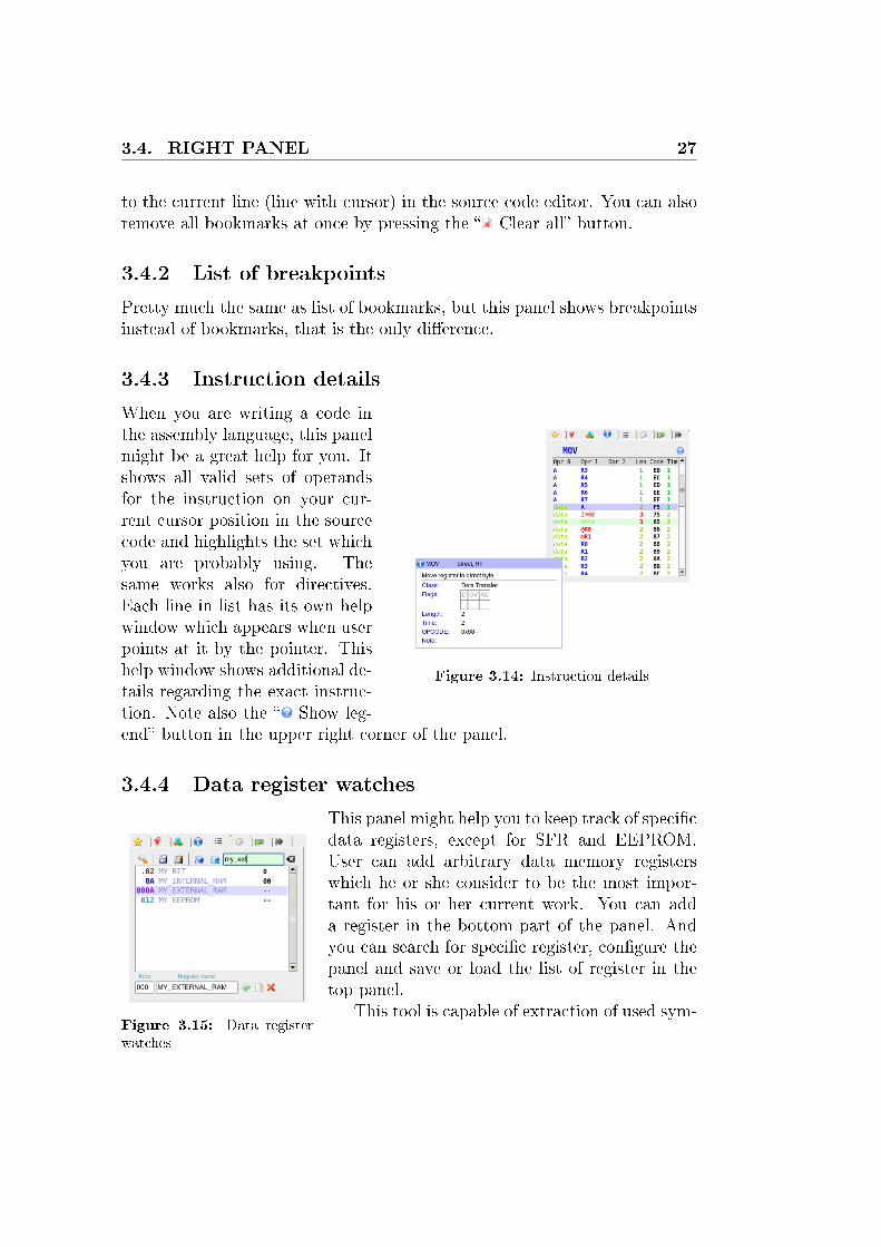
When you are writing a code inthe assembly language, this panelmight be a great help for you. Itshows all valid sets of operandsfor the instruction on your cur-rent cursor position in the sourcecode and highlights the set whichyou are probably using. Thesame works also for directives.Each line in list has its own helpwindow which appears when userpoints at it by the pointer. Thishelp window shows additional de-tails regarding the exact instruc-tion. Note also the � Show leg-end� button in the upper right corner of the panel.
3.4.4 Data register watches
Figure 3.15: Data registerwatches
This panel might help you to keep track of speci�cdata registers, except for SFR and EEPROM.User can add arbitrary data memory registerswhich he or she consider to be the most impor-tant for his or her current work. You can adda register in the bottom part of the panel. Andyou can search for speci�c register, con�gure thepanel and save or load the list of register in thetop panel.
This tool is capable of extraction of used sym-

28 CHAPTER 3. DETAILED INTRODUCTION TO GUI
bols from a code listing �le8 generated by an as-sembler. This feature can enabled or disabled inthe panel's con�guration menu. The current list
of watched registers can be saved into a �le and loaded from a �le9.Memory segments are distinguished by format of the addresses. As you
can seen in the example, the meaning is this:
Address format Memory segment
1 or 2 digits Internal RAM (not SFR)3 digits Expanded RAM4 digits External RAMdot and 2 digits Bit (including SFR area)
Table 3.2: Data register watches: Register address
3.4.5 Subprograms call monitor
Figure 3.16: Subprogramscall monitor
From here you can monitor all subprogram andinterrupt calls in your program. For each en-try there is mentioned the type of call, acall,lcall or interrupt, return address and addressfrom which the call was invoked. And you canforce each of them to premature return.
3.4.6 List of symbols
This tools shows a list of symbols de�ned insource code of your program, works for both as-sembly language and C language. The list is man-aged automatically as the user edit the code andis featured with search panel for easy navigation.Types of symbols can be distinguished by their colors and icons. Colors ofparticular symbols corresponds to the colors used in the source code editorto highlight them.
3.4.7 HW plug-ins manager
This tool does just one thing, allows user to use plug-ins in MCU 8051 IDE.Primary purpose of these plug-ins should be implementation of inter-operation
8File with .lst �le name extension.9These �le usually have extension .wtc

3.5. OTHER TOOLS 29
Label
Constant
Macro
C variable
C function
Other
Table 3.3: Symbol colors and icons in default settings
with certain hardware tools, most probably MCU programmers. if you areinterested in writing these plug-ins, please refer to chapter 7.
3.5 Other tools
3.5.1 SFR map
A tabular overview of all available SFRs on your MCU. This tool has similargraphical form as tables of SFR often used in 8051 manuals, but the mostimportant di�erence is that this one is connected to the simulator and iscapable of representing and modifying current values of SFRs in the MCUsimulator.
3.5.2 Map of bit addressable area
Figure 3.17: Map of the bit ad-dressable area
This tool is a part of the simulator userinterface. It shows all bits in the bit ad-dressable area of the simulated MCU. Eachsquare represents one bit, when simulatoris on, you can also change value of each oneof them by clicking on it. Labels and colorused here should be hopefully clear from
the legend at the bottom.
3.5.3 Stack monitor
Figure 3.18: Stackmonitor
This tool makes it possible to see entire MCU stack inone view. You can also push any value you want onto thestack or pop a value from it at any time. However thisparticular tool does not allow for changing the values onthe tack in any other way than these.
Each line in the stack monitor represents one octetin the stack, each octet is represented in four numerical
30 CHAPTER 3. DETAILED INTRODUCTION TO GUI
bases, hexadecimal, decimal, binary and octal and also asa character according to ACII chart. Newly added valuesare pushed on the top of the list. And their origins aredistinguished by background color of the address. These colors are explainedin the legend on bottom.
Note that button �Clear� doe not clear the stack but instead it clear onlythe monitor! Buttons �POP� and �PUSH� are intended for manipulationwith the stack's content.
3.5.4 Symbol viewer
Figure 3.19: Symbol viewer
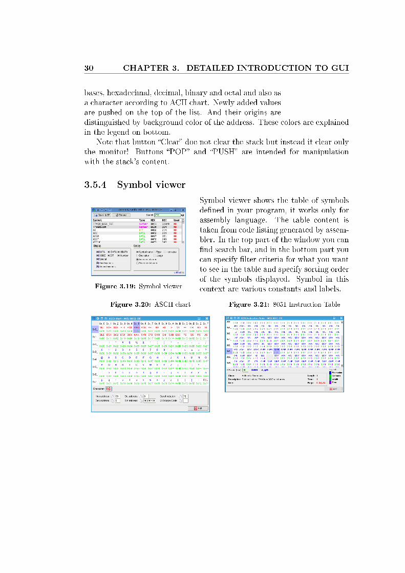
Symbol viewer shows the table of symbolsde�ned in your program, it works only forassembly language. The table content istaken from code listing generated by assem-bler. In the top part of the window you can�nd search bar, and in the bottom part youcan specify �lter criteria for what you wantto see in the table and specify sorting orderof the symbols displayed. Symbol in thiscontext are various constants and labels.
Figure 3.20: ASCII chart Figure 3.21: 8051 Instruction Table
3.5. OTHER TOOLS 31
3.5.5 ASCII chart
Colorful interactive ASCII chart, it may proof handy especially when youare dealing with serial communication and this sort of things.
3.5.6 8051 Instruction Table
Colorful interactive 8051 instruction table, very much alike the ASCII chart.But instead of ASCII code you can �nd there the complete table of 8051instruction mnemonics, OP codes and related things.
3.5.7 8-segment editor
Figure 3.22: 8-segment editor
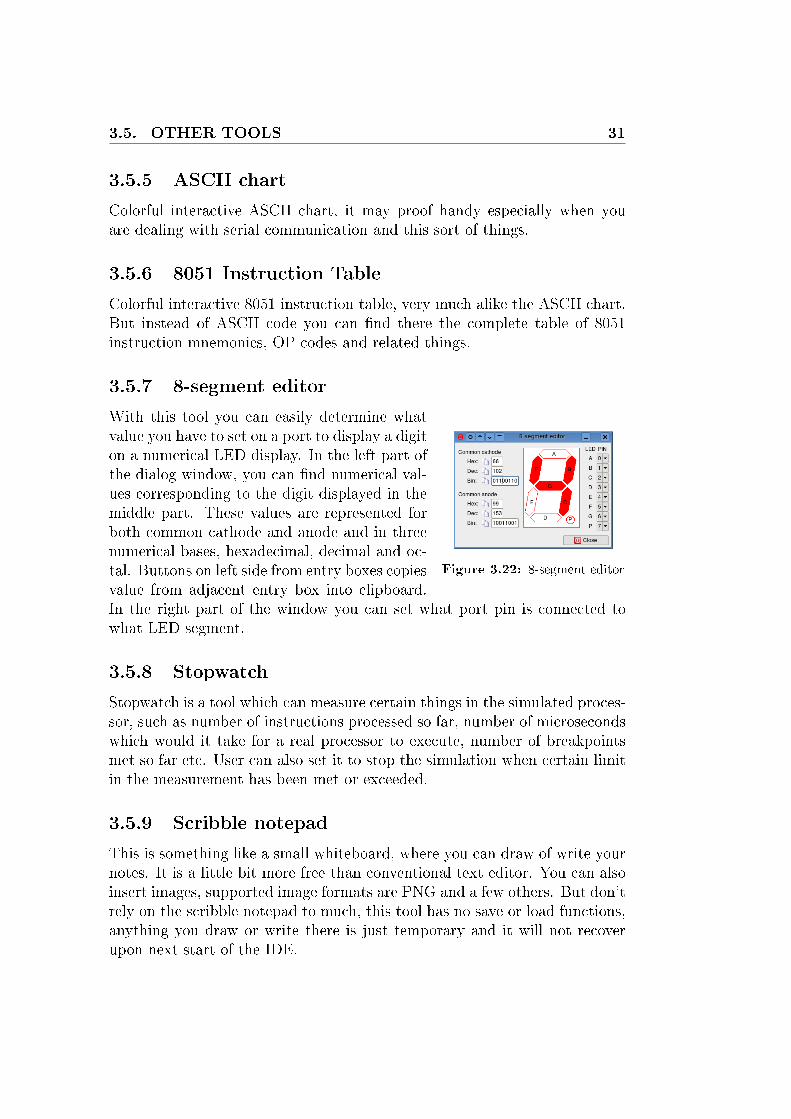
With this tool you can easily determine whatvalue you have to set on a port to display a digiton a numerical LED display. In the left part ofthe dialog window, you can �nd numerical val-ues corresponding to the digit displayed in themiddle part. These values are represented forboth common cathode and anode and in threenumerical bases, hexadecimal, decimal and oc-tal. Buttons on left side from entry boxes copiesvalue from adjacent entry box into clipboard.In the right part of the window you can set what port pin is connected towhat LED segment.
3.5.8 Stopwatch
Stopwatch is a tool which can measure certain things in the simulated proces-sor, such as number of instructions processed so far, number of microsecondswhich would it take for a real processor to execute, number of breakpointsmet so far etc. User can also set it to stop the simulation when certain limitin the measurement has been met or exceeded.
3.5.9 Scribble notepad
This is something like a small whiteboard, where you can draw of write yournotes. It is a little bit more free than conventional text editor. You can alsoinsert images, supported image formats are PNG and a few others. But don'trely on the scribble notepad to much, this tool has no save or load functions,anything you draw or write there is just temporary and it will not recoverupon next start of the IDE.

32 CHAPTER 3. DETAILED INTRODUCTION TO GUI
3.5.10 Base converter
Figure 3.23: Base conver-tor
When you are programming micro-controllers, youmight want to convert numbers between various nu-meric bases. One could say that everyone dealingwith such things as micro-controllers would be ableto do these conversion without use of any tool. Butthis doesn't mean that such a tool can never beuseful. Values written in the entry boxes of thebase converter are saved when user leaved the IDE
and are recovered upon next start along with all opened base converter toolwindows.
3.5.11 RS-232 debugger
Figure 3.24: UART/RS-232 debugger
This tool is capable of transmittingand receiving data to/from RS-232port in your computer, today per-sonal computers usually do not havethis type of port, but you can alwaysuse something like a USB to RS-232bridge.
I assume here that the reader isfamiliar with the RS-232 communica-tion protocol and related terms. Thistool acts as a DTE10.
On the diagram in the upper leftcorner you can see current logicallevel on each of RS-232 wires except for RxD and TxD. You can also set valuefor wires DTR11 and RTS12 and trigger the break by button BREAK.
Right upper corner contains con�guration controls, their functions shouldbe mostly obvious. Check-box �Enable reception� enables or disables writingto hexadecimal editor �Received data�. Button �Close� closes the openedphysical port. And button � � refreshes the list of available physical ports.
In the bottom part you can see two hexadecimal editors: �Data to send�and �Received data�. These are representations of data which we are dealingwith. By button �Receive here� you can set address in the hexadecimal editor
10Data Terminal Equipment, the other side is DCE (Data Circuit-terminating Equip-ment).
11Data Terminal Ready12Ready To Send

3.5. OTHER TOOLS 33
where the received data will be written. And by button �Send selected� youcan trigger transmission over the opened physical port, selected chunk of thedata will be send then. Button �Clear selected� are intended for removingdata from the hexadecimal editors editors.
3.5.12 Hexadecimal editors
Figure 3.25: MCU code memory editor
In this IDE there are several hex-adecimal editors used for variouspurposes. Each of these editors isequipped with a string search tooland address bars of the left andtop side. And in some cases with�le saving and loading capability,numerical base switch, ASCII viewand a navigation bar at the bottom.Editing is allowed only in overwritemode, copy and paste works asusual, search dialog can be invokedby pressing Ctrl+F and user canswitch between view (left and right)by pressing Tab key. Non printable
characters in ASCII view are displayed in red color.
MCU code memory editor allows user to see and modify contents ofthe CODE memory of the simulated micro-controller. Special feature of thisparticular editor is that instruction OP code currently pointed by programcounter (PC) is highlighted with dark orange background along with theinstruction's operands. And the same applies also for the previously executedinstruction but highlight color is light orange in this case.
MCU data/xdata/eeprom memory editor allows user to see and mod-ify contents of the IDATA/XDATA/EEPROM memory of the simulatedmicro-controller. Special features of this editors are that recently changedoctets are highlighted with light orange foreground color and octets currentlybeing written into the memory are highlighted with gray background color.
MCU eeprom write bu�er editor allows to see and modify EEPROMwrite bu�er. Current EEPROM write o�set is displayed as well.

34 CHAPTER 3. DETAILED INTRODUCTION TO GUI
Independent hexadecimal editor is universal hexadecimal editor withmaximum capacity of 64kB and support for Intel R©8 HEX �le format. Thistool is completely independent from your project in the IDE. This too mightbe particularly useful when you want to and possibly modify content of aIntel R©8 hex �le, but do not alter the simulated MCU.
3.5.13 Hibernation of simulated program
The IDE is capable of saving execution state of the simulated program intoa �le and resuming the program from it anytime later. The �le, usuallywith extension .m5ihib, contains values of all data registers including SFRin the simulated MCU along with other values determining MCU state as forexample list of active interrupts. The �le is in XML format, human readableand usually occupies a few tens of kilobytes.The �le does not contain contentof the CODE memory, so it has to be available somewhere else in a separate�le.
3.5.14 Interrupt monitor
Interrupts monitor is a specialized tool intended for viewing and manipu-lating with interrupts in simulated MCU. With interrupt monitor you caninvoke any interrupt you want at any time, force any interrupt at any time toreturn, change interrupt priorities or disable or enable particular interrupts.You can also see all interrupts synoptically in one window and alter valuesof their con�guration �ags.
Figure 3.26: Interrupt monitor

3.5. OTHER TOOLS 35
3.5.15 Conversions between *.hex, *.bin and *.adf �les
Sometimes it might prove helpful to have some tool to convert a binary �leto Intel R©8 Hex and vice versa. For this purpose MCU 8051 IDE is equippedwith a simple tool set for this purpose. In the �Main Menu� → �Utilities�you can �nd these tools:
• HEX → BINConvert Intel R©8 Hex �le to raw binary �le
• BIN → HEXConvert raw binary �le to Intel R©8 Hex
• SIM → HEXConvert simulator assembler debug �le (.adf) to Intel R©8 Hex �le
• SIM → BINConvert simulator assembler debug �le (.adf) to raw binary �le
• Normalize HexRead and rewrite the given Intel R©8 Hex �le, so that all records satis�esspeci�ed maximum length (can be set in the assembler con�gurationdialog), all records are in incremental order and no records overlapswith others.
3.5.16 Normalization of source code indentation
Uniformly indented code is always more aesthetically pleasing and more read-able. When you don't have the luxury of having such a code from the �rsthand, perhaps you will �nd this feature helpful. This function is availablefor assembly language and C language if program indent is installed on yoursystem. User can access this function from the �Main Menu� → �Tools� →�Auto indent�.
A small example of the auto indent function in action
Original code:abc DATA 7Fh
; Start at address 0x00
ORG 0h
label0:inc R0
inc @R0
cjne R0 , #abc ,label0
mov R0, #0h
sjmp label0
; End of assembly
END
Automatically intended code:abc DATA 7Fh
; Start at address 0x00
ORG 0h
label0: inc R0
inc @R0
cjne R0, #abc, label0
mov R0, #0h
sjmp label0
; End of assembly
END
3.5.17 Change letter case

36 CHAPTER 3. DETAILED INTRODUCTION TO GUI
Figure 3.27: Change letter casedialog
This tool can change letter casing to upperor lower case of certain types tokens whichyour source consists of of. For example youcan easily convert all instruction mnemonicsin the code to uppercase. It is intended forusers who strictly prefers one or another con-vention of letter casing in assembly language.You can invoke the tool from �Main Menu� →�Tools� → �Change letter case�.
• Convert to uppercase
• Convert to lowercase
• Keep current case
3.5.18 User de�ned commands
Introduction This feature was added in order to enable for use of any aux-iliary tools which might useful while working in this IDE. For instance, somehardware tools or some sort of a source code management system like Gitor SVN. These custom commands are basically mere Bash scripts with somekind of pseudo-variables available in it. These pseudo-variables are formed asstrings beginning with �%�. Before each script execution they are expandedto values corresponding to their meaning. For instance �%filename� expandsto the name of the current �le. Note that �%%� is expanded as single �%�.
Pseudo-variable Meaning
%URL The full URL of the current �le%URLS List of the URLs of all open documents%directory Project directory%�lename The �le name of the current document%basename Same as %�lename, but without extension%main�le Name of project main �le%line Number of the current line%column Number of the current column%selection The selected text in the current �le%text The full text of the current �le
Table 3.4: List of pseudo-variables
Con�guration There is specialized con�guration dialog for these customcommands.
3.6. CONFIGURATION DIALOGUES 37
Figure 3.28: Custom commandscon�guration dialog
Execution After the script is executed suc-cessfully or not, dialog showing the resultswill appear upon completion of the script.This dialog contains all textual output fromthe script caught on standard output andstandard error output. If the script outputsanything to the standard error output it isconsidered unsuccessful.
3.5.19 Clean-up project folder
This tool can proof useful particularly whenyour project directory gets �polluted� withlots of unnecessary �les, and you want to getrid of them easily and �rst of all safely. It removes �les with certain �lename extensions from the project folder. The list of removed �les is thenwritten in results dialog. Available from �Main Menu� → �Tools� → �Cleanup project folder�.
3.5.20 File statistic
Display certain statistical information about the current source code �le.�Main Menu� → �File� → �File statistic�.
3.6 Con�guration dialogues
Con�guration dialogues are graphical tools for customization of this inte-grated development environment. And they comprises of these components:
Figure 3.29: Editorcon�guration dialog
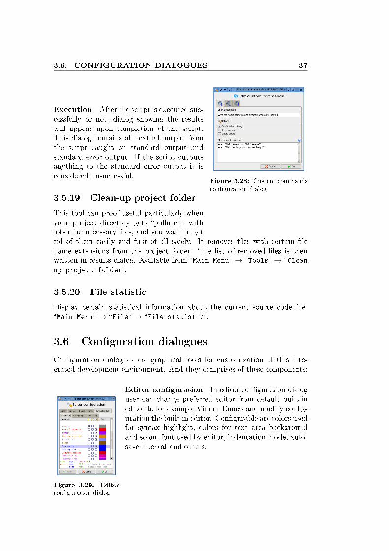
Editor con�guration In editor con�guration dialoguser can change preferred editor from default built-ineditor to for example Vim or Emacs and modify con�g-uration the built-in editor. Con�gurable are colors usedfor syntax highlight, colors for text area backgroundand so on, font used by editor, indentation mode, auto-save interval and others.
38 CHAPTER 3. DETAILED INTRODUCTION TO GUI
Compiler con�guration Compiler con�guration di-alog allows user to con�gure behavior of the built-inassembler, chose another assembler instead of this one.Con�gure the preferred assembler and con�gure the Ccompiler (SDCC). Compiler con�guration is stored inthe project �le (the �le with .mcu8051ide extension).
So these setting are speci�c to the one speci�c MCU 8051 IDE project.Currently supported external assemblers are these:
• ASEM-51 13
• ASL 14
• AS51 15
How to link multiple �les when using C language:16
1. Write make�le,
2. set the IDE to use your make�le instead of calling the C compiler di-rectly (Con�guration -> Compiler con�guration -> GNU make utility),
3. start compilation as usual.
Simulator con�guration Simulator con�guration dialog con�gures these:
1. How to treat indeterminable values in simulator engine
2. How many steps will be remembered during the simulation for laterbackward steps.
3. What warning conditions will be ignored during the simulation
Right panel con�guration Con�gures colors used in tools �Instructiondetails� and �Register watches� in the right panel.
Main toolbar con�guration Con�gures contents of main application toolbar.
13A really useful assembler written by W.W. Heinz. You can �nd it at http://plit.de/asem-51/home.htm
14Available at http://linux.maruhn.com/sec/asl.html15Available at http://www.pjrc.com/tech/805116This feature is not yet supported on MS Windows.
3.6. CONFIGURATION DIALOGUES 39
Figure 3.30: Main toolbar
Custom commands con�guration Con�gures user de�ned commands,which are essentially Bash scripts. This feature is currently not available onMS R©Windows R©OS.
Shortcuts con�guration Con�gures key shortcuts used in the IDE.
Terminal emulator con�guration Con�gures terminal emulator at thebottom panel. This terminal emulator is embedded rxvt-unicode. User canset foreground color and background color of the terminal emulator windowand the font. This feature is currently not available on MS R©Windows R©OS.
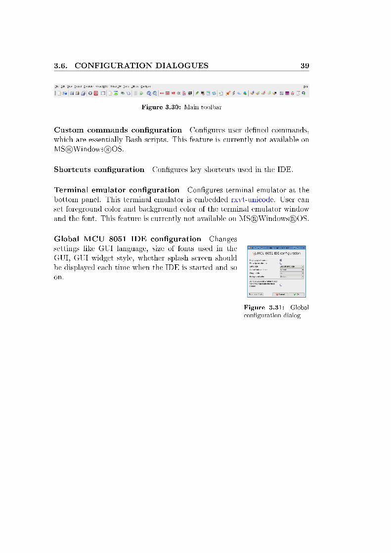
Figure 3.31: Globalcon�guration dialog
Global MCU 8051 IDE con�guration Changessettings like GUI language, size of fonts used in theGUI, GUI widget style, whether splash screen shouldbe displayed each time when the IDE is started and soon.

40 CHAPTER 3. DETAILED INTRODUCTION TO GUI
41
Chapter 4
Build-in macro-assembler
In this chapter we will be concerned with MCU 8051 IDE build-in assembler.1 With syntax of its statements, directives and 8051 assembler instructions. Iassume that the reader is familiar with general concepts of assembly languageprogramming and 8051 architecture. So I will not explain these here.
4.1 Statements
Source code �les for this assembler must be text �les where lines are formedlike these:
[ label: ] [ instruction [ operand [ , operand [ , operand ] ] ] [ ;comment ]
[ label: ] directive [ argument ] [ ;comment ]
symbol directive argument [ ;comment ]
Everything in square brackets is optional. Compilation does not go be-yond line containing �end� directive, so after that directive the code do nothave to be syntactically valid. Empty lines are allowed as well as line contain-ing only comment or label. Statements can be separated by spaces, NBSPcharacters2 and tabs. Statements are case insensitive and their length is notlimited, overall line length is also not limited.
4.2 Symbols
Symbol names for numbers, macros or addresses de�ned by user in the codeusing appropriate directive. Like with �equ� directive you can de�ne a new
1This assembler manual is inspired by ASEM-51 manual, a great work done by W.W.Heinz
2No Breaking Space (0xC2)
42 CHAPTER 4. BUILD-IN MACRO-ASSEMBLER
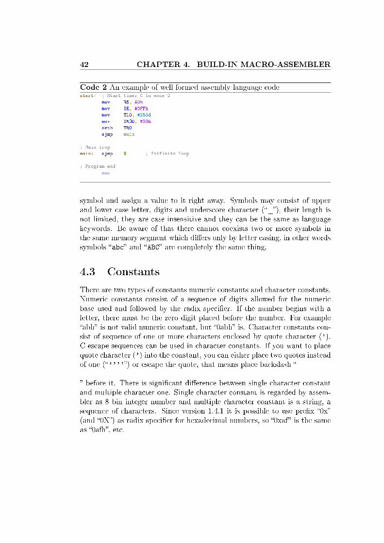
Code 2 An example of well formed assembly language codestart: ; Start timer 0 in mode 2
mov R5, #0h
mov IE, #0FFh
mov TL0, #255d
mov TMOD, #03h
setb TR0
sjmp main
; Main loop
main: sjmp $ ; Inifinite loop
; Program end
end
symbol and assign a value to it right away. Symbols may consist of upperand lower case letter, digits and underscore character (�_�), their length isnot limited, they are case insensitive and they can be the same as languagekeywords. Be aware of that there cannot coexists two or more symbols inthe same memory segment which di�ers only by letter casing, in other wordssymbols �abc� and �ABC� are completely the same thing.
4.3 Constants
There are two types of constants numeric constants and character constants.Numeric constants consist of a sequence of digits allowed for the numericbase used and followed by the radix speci�er. If the number begins with aletter, there must be the zero digit placed before the number. For example�abh� is not valid numeric constant, but �0abh� is. Character constants con-sist of sequence of one or more characters enclosed by quote character (').C escape sequences can be used in character constants. If you want to placequote character (') into the constant, you can either place two quotes insteadof one (�''''�) or escape the quote, that means place backslash �
� before it. There is signi�cant di�erence between single character constantand multiple character one. Single character constant is regarded by assem-bler as 8 bin integer number and multiple character constant is a string, asequence of characters. Since version 1.4.1 it is possible to use pre�x �0x�(and �0X�) as radix speci�er for hexadecimal numbers, so �0xaf� is the sameas �0afh�, etc.

4.4. EXPRESSIONS 43
Constant type Allowed digits Radix speci�er
Binary 0 .. 1 BOctal 0 .. 7 O or QDecimal 0 .. 9 D or noneHexadecimal 0 .. 9, A .. F H
Table 4.1: Radix speci�ers
Code 3 An example of constants; These are the same number
a set 100111b ; Binary
a set 47q ; Octal
a set 39d ; Decimal
a set 27h ; Hexadecimal
a set '''' ; Character
; This is an example of string
db 'string' ; String
4.4 Expressions
Arithmetical expressions are evaluated at compilation time and replaced byassembler with constant corresponding the their resulting value. Expressionscomprises of arithmetical operators, constants, symbols and another expres-sions. An example of such expression might be ( X XOR 0FF00H )
Operator Description Example
Unary Operators
NOT one's complement NOT 0a55ah
HIGH high order byte HIGH 0a55ah
LOW low order byte LOW 0a55ah
Binary Operators
+ unsigned addition 11 + 12
- unsigned subtraction 13 + 11
* unsigned multiplication 3 * 5
/ unsigned division 20 / 4
MOD unsigned remainder 21 MOD 4
SHL logical shift left 32 SHL 2
SHR logical shift right 32 SHR 2
AND logical and 48 AND 16
OR logical or 370q OR 7
XOR exclusive or 00fh XOR 005h
. bit operator P1.4
EQ, = equal to 11 EQ 11
NE, <> not equal to 11 NE 11
LT, < less than 11 LT 12
LE, <= less or equal than 11 LT 11
GT, > greater than 12 GT 11
GE, >= greater or equal than 12 GT 11
Table 4.2: Expression operators

44 CHAPTER 4. BUILD-IN MACRO-ASSEMBLER
Code 4 An example of expressionsabc EQU ( 2000 * 3 / 100 )
xyz SET ( LOW abc )
IF ( abc > ( 5 MOD 2 ) )
MOV A, # ( ( 15h XOR 12 ) OR xyz )
ELSE
ADDC A, # ( HIGH 1234h )
ENDIF
4.5 The instruction set processing
This assembler is capable of translating all 8051 instructions with all possiblesets of operands. And extends this set with 2 pseudo-instructions: �CALL�and �JMP� which do not stand for any operation code, but are translatedaccording to the used operand. �CALL� can be translated as �ACALL� or�LCALL�, �JMP addr� can be translated as �SJMP�, �AJMP� or �LJMP�.

4.6. ASSEMBLER DIRECTIVES 45
4.6 Assembler directives
ifn IF Not, conditional assemblySyntax:IFN <expr>
Example:IF(2 * 4 - CND)
MOV A, #20h
ELSE
MOV A, #40h
ENDIF
ifdef IF DEFinedSyntax:
IFDEF <symbol>
Example:IFDEF CND
MOV A, #20h
ELSE
MOV A, #40h
ENDIF
ifndef IF Not DEFinedSyntax:
IFNDEF <symbol>
Example:IFNDEF CND
MOV A, #20h
ELSE
MOV A, #40h
ENDIF
rept REPeaT MacroSyntax:
REPT <expr>
Example:REPT 5
NOP
ENDM
times REPeaT MacroSyntax:
TIMES <expr>
Example:TIMES 5
NOP
ENDM
if Conditional assemblySyntax:
IF <expr>
Example:IF(2 * 4 - CND)
MOV A, #20h
ELSE
MOV A, #40h
ENDIF
else Conditional assemblySyntax:
ELSE
Example:IF(2 * 4 - CND)
MOV A, #20h
ELSE
MOV A, #40h
ENDIF
elseif Conditional assemblySyntax:
ELSEIF <expr>
Example:IF(2 * 4 - CND)
MOV A, #20h
ELSEIF SOMETHING_ELSE
MOV A, #40h
ENDIF
elseifn Conditional assemblySyntax:
ELSEIF <expr>
Example:IF(2 * 4 - CND)
MOV A, #20h
ELSEIF SOMETHING_ELSE
MOV A, #40h
ENDIF
elseifdef Conditional assemblySyntax:
ELSEIF <expr>
Example:IF(2 * 4 - CND)
MOV A, #20h

46 CHAPTER 4. BUILD-IN MACRO-ASSEMBLER
ELSEIFDEF SOMETHING_ELSE
MOV A, #40h
ENDIF
elseifndef Conditional assemblySyntax:
ELSEIF <expr>
Example:IF(2 * 4 - CND)
MOV A, #20h
ELSEIFNDEF SOMETHING_ELSE
MOV A, #40h
ENDIF
endif Conditional assemblySyntax:
ENDIF
Example:IF(2 * 4 - CND)
MOV A, #20h
ELSE
MOV A, #40h
ENDIF
endm END of Macro de�nitionSyntax:
ENDM
Example:ABC MACRO
MOV B, #12d
ENDM
end END of the programSyntax:
END
Example:END
list enable code LISTingSyntax:
LIST
Example:NOP
NOLIST
NOP
NOP
LIST
NOP
nolist disabled code listingSyntax:
NOLIST
Example:NOP
NOLIST
NOP
NOP
LIST
NOP
dseg switch to DATA segment [at address]Syntax:
DSEG [AT <expr>]
Example:DSEG at 20d
iseg switch to IDATA segment [at address]Syntax:
ISEG [AT <expr>]
Example:ISEG at 10d
bseg switch to BIT segment [at address]Syntax:
BSEG [AT <expr>]
Example:BSEG at 5d
xseg switch to XDATA segment [at address]Syntax:
XSEG [AT <expr>]
Example:XSEG at 30d
cseg switch to CODE segment [at address]Syntax:
CSEG [AT <expr>]
4.6. ASSEMBLER DIRECTIVES 47
Example:CSEG at 40d
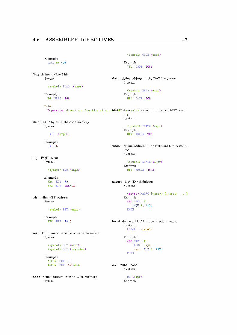
�ag de�ne a FLAG bitSyntax:
<symbol> FLAG <expr>
Example:F4 FLAG 16h
Note:
Deprecated directive. Consider directive BIT instead.}
skip SKIP bytes in the code memorySyntax:
SKIP <expr>
Example:SKIP 5
equ EQUivalentSyntax:
<symbol> EQU <expr>
Example:ABC EQU R0
XYZ EQU 4Eh+12
bit de�ne BIT addressSyntax:
<symbol> BIT <expr>
Example:ABC BIT P4.5
set SET numeric variable or variable registerSyntax:
<symbol> SET <expr>
<symbol> SET <register>
Example:ALPHA SET R0
ALPHA SET 42*BETA
code de�ne address in the CODE memorySyntax:
<symbol> CODE <expr>
Example:TBL CODE 600h
data de�ne address in the DATA memorySyntax:
<symbol> DATA <expr>
Example:UIV DATA 20h
idata de�ne address in the Internal DATA mem-orySyntax:
<symbol> IDATA <expr>
Example:UIV IDATA 20h
xdata de�ne address in the External DATA mem-orySyntax:
<symbol> XDATA <expr>
Example:UIV XDATA 400h
macro MACRO de�nitionSyntax:
<macro> MACRO [<arg0> [,<arg1> ... ]
Example:ABC MACRO X
MOV X, #12d
ENDM
local de�ne a LOCAL label inside a macroSyntax:LOCAL <label>
Example:ABC MACRO X
LOCAL xyz
xyz: MOV X, #12d
ENDM
ds De�ne SpaceSyntax:
DS <expr>
Example:

48 CHAPTER 4. BUILD-IN MACRO-ASSEMBLER
DS 2+4
dw De�ne WordsSyntax:
DW <expr1> [,<expr2> ... ]
Example:DW 0,02009H,2009,4171
db De�ne BytesSyntax:
DB <expr1> [,<expr2> ... ]
Example:DB 24,'August',09,(2*8+24)/8
dbit De�ne BITsSyntax:
DBIT <expr>
Example:DBIT 4+2
include INCLUDE an external source codeSyntax:
INCLUDE <filename>
Example:INCLUDE 'my file.asm'
org ORiGin of segment locationSyntax:
ORG <expr>
Example:ORG 0Bh
using USING register banksSyntax:
USING <expr>
Example:USING 2
byte de�ne BYTE address in the data memorySyntax:
<symbol> BYTE <expr>
Example:UIV BYTE 20h
Note:
Deprecated directive. Consider directive DATA instead.

4.7. ASSEMBLER CONTROLS 49
4.7 Assembler Controls
$date Inserts date string into page headerSyntax:$DATE(string)
Example:$DATE(1965-12-31)
$da Inserts date string into page headerSyntax:
$DA(string)
Example:$DA(1965-12-31)
$eject Start a new page in list �leSyntax:$EJECT
Example:$EJECT
$ej Start a new page in list �leSyntax:$EJ
Example:$EJ
$include Include a source �leSyntax:$INCLUDE(string)
Example:$INCLUDE(somefile.asm)
$inc Include a source �leSyntax:$INC(string)
Example:$INC(somefile.asm)
$list List subsequent source linesSyntax:$LIST
Example:$LIST
$li List subsequent source linesSyntax:$LI
Example:$LI
$noli Don't list subsequent source linesSyntax:$NOLI
Example:$NOLI
$nolist Don't list subsequent source linesSyntax:$NOLIST
Example:$NOLIST
$nomod Disable prede�ned SFR symbolsSyntax:$NOMOD
Example:$NOMOD
$nomo Disable prede�ned SFR symbolsSyntax:$NOMO
Example:$NOMO
$nomod51 Disable prede�ned SFR symbolsSyntax:$NOMOD51
Example:$NOMOD51
$paging Enable listing page formattingSyntax:$PAGING
Example:$PAGING
$pi Enable listing page formattingSyntax:$PI
Example:$PI
$nopi Disable listing page formattingSyntax:$NOPI
Example:$NOPI
$nopaging Disable listing page formattingSyntax:$NOPAGING

50 CHAPTER 4. BUILD-IN MACRO-ASSEMBLER
Example:$NOPAGING
$pagelength Set lines per page for listingSyntax:$PAGELENGTH(int)
Example:$PAGELENGTH(64)
$pl Set lines per page for listingSyntax:$PL(int)
Example:$PL(64)
$pagewidth Set columns per line for listingSyntax:$PAGEWIDTH(int)
Example:$PAGEWIDTH(132)
$pw Set columns per line for listingSyntax:$PW(int)
Example:$PW(132)
$symbols Create symbol tableSyntax:$SYMBOLS
Example:$SYMBOLS
$sb Create symbol tableSyntax:$SB
Example:$SB
$nosymbols Don't create symbol tableSyntax:$NOSYMBOLS
Example:$NOSYMBOLS
$nosb Don't create symbol tableSyntax:$NOSB
Example:$NOSB
$title Inserts title string into page headerSyntax:$TITLE(string)
Example:$TITLE(My firts code)
$tt Inserts title string into page headerSyntax:$TT(string)
Example:$TT(My firts code)
$noobject Do not create Intel HEX �leSyntax:$NOOBJECT
Example:$NOOBJECT
$object Specify �le name for Intel HEXSyntax:$OBJECT(string)
Example:$OBJECT(my_hex.hex)
$print Specify �le name for list �leSyntax:$PRINT(string)
Example:$PRINT(my_list.lst)
$noprint Do not create list �le at allSyntax:$NOPRINT
Example:$NOPRINT
$nomacros�rst De�ne and expand macro instruc-tions after! conditional assembly and de�-nitions of constantsSyntax:$NOMACROSFIRST
Example:$NOMACROSFIRST

4.8. PREDEFINED SYMBOLS 51
4.8 Prede�ned Symbols
There are symbols which are de�ned by default by assembler. The aim is tomake it a little easier to write code in assembly language for 8051, becauseuser don not have to de�ne all these symbols in his or her code. This featurecan be turned of by �$NOMOD� control sequence.
Table 4.3: Code addresses
Symbol Value Symbol Value Symbol Value Symbol Value
RESET 000h EXTI0 003h TIMER0 00Bh EXTI1 013hTIMER1 01Bh SINT 023h TIMER2 02Bh CFINT 033h
Table 4.4: Plain numbers, these symbols are always de�ned!
Symbol Value
??MCU_8051_IDE 8051h??VERSION 0139h 3
Table 4.5: Prede�ned SFR bit addresses
Symbol Value Symbol Value Symbol Value Symbol Value
IT0 088h IE0 089h IT1 08Ah IE1 08BhTR0 08Ch TF0 08Dh TR1 08Eh TF1 08FhRI 098h TI 099h RB8 09Ah TB8 09BhREN 09Ch SM2 09Dh SM1 09Eh SM0 09FhFE 09FhEX0 0A8h ET0 0A9h EX1 0AAh ET1 0ABhES 0ACh ET2 0ADh EC 0AEh EA 0AFhRXD 0B0h TXD 0B1h INT0 0B2h INT1 0B3hT0 0B4h T1 0B5h WR 0B6h RD 0B7hPX0 0B8h PT0 0B9h PX1 0BAh PT1 0BBhPS 0BCh PT2 0BDh PC 0BEhPPCL 0BEh PT2L 0BDh PSL 0BChPT1L 0BBh PX1L 0BAh PT0L 0B9h PX0L 0B8hTF2 0CFh EXF2 0CEh RCLK 0CDh TCLK 0CChEXEN2 0CBh TR2 0CAh CT2 0C9h CPRL2 0C8hP 0D0h OV 0D2h RS0 0D3hRS1 0D4h F0 0D5h AC 0D6h CY 0D7hCR 0DEh CCF4 0DChCCF3 0DBh CCF2 0DAh CCF1 0D9h CCF0 0D8h
52 CHAPTER 4. BUILD-IN MACRO-ASSEMBLER
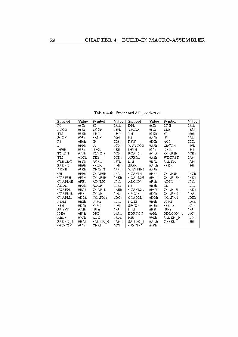
Table 4.6: Prede�ned SFR addresses
Symbol Value Symbol Value Symbol Value Symbol Value
P0 080h SP 081h DPL 082h DPH 083hPCON 087h TCON 088h TMOD 089h TL0 08AhTL1 08Bh TH0 08Ch TH1 08Dh P1 090hSCON 098h SBUF 099h P2 0A0h IE 0A8hP3 0B0h IP 0B8h PSW 0D0h ACC 0E0hB 0F0h P4 0C0h WDTCON 0A7h EECON 096hDP0H 083h DP0L 082h DP1H 085h DP1L 084hT2CON 0C8h T2MOD 0C9h RCAP2L 0CAh RCAP2H 0CBhTL2 0CCh TH2 0CDh AUXR1 0A2h WDTRST 0A6hCLKREG 08Fh ACSR 097h IPH 0B7h SADDR 0A9hSADEN 0B9h SPCR 0D5h SPSR 0AAh SPDR 086hAUXR 08Eh CKCON 08Fh WDTPRG 0A7h
CH 0F9h CCAP0H 0FAh CCAP1H 0FBh CCAP2H 0FChCCAP3H 0FDh CCAP4H 0FEh CCAPL2H 0FCh CCAPL3H 0FDhCCAPL4H 0FEh ADCLK 0F2h ADCON 0F3h ADDL 0F4hADDH 0F5h ADCF 0F6h P5 0E8h CL 0E9hCCAP0L 0EAh CCAP1L 0EBh CCAPL2L 0ECh CCAPL3L 0EDhCCAPL4L 0EEh CCON 0D8h CMOD 0D9h CCAPM0 0DAhCCAPM1 0DBh CCAPM2 0DCh CCAPM3 0DDh CCAPM4 0DEhP1M2 0E2h P3M2 0E3h P4M2 0E4h P1M1 0D4hP3M1 0D5h P4M1 0D6h SPCON 0C3h SPSTA 0C4hSPDAT 0C5h IPL0 0B8h IPL1 0B2h IPH1 0B3hIPH0 0B7h BRL 09Ah BDRCON 09Bh BDRCON_1 09ChKBLS 09Ch KBE 09Dh KBF 09Eh SADEN_0 0B9hSADEN_1 0BAh SADDR_0 0A9h SADDR_1 0AAh CKSEL 085hOSCCON 086h CKRL 097h CKCON0 08Fh

4.9. SEGMENT TYPE 53
4.9 Segment type
Segment type speci�es the address space to which a symbol is assigned. Forexample if you de�ne symbol ABC using �XDATA� directive, then ABS isassigned to XDATA segment. Purpose of this is to semantically distinguishbetween di�erent types of symbols. For example if we use a symbol as addressto program memory it has di�erent meaning that if we used it as address tobit addressable area.
DATA Internal data memory and SFRIDATA Internal data memory onlyXDATA External data memory onlyBIT Bit addressable area onlyCODE Program memory onlyNUMBER Arbitrary value
Table 4.7: Segment types
Symbols might be assigned to these segment types by these directives:
• DATA (segment DATA)
• IDATA (segment IDATA)
• XDATA (segment XDATA)
• BIT (segment BIT)
• CODE (segment CODE)
• EQU, SET (segment NUMBER)
Code 5 Example of symbol de�nitionsMY_A DATA '\n' ; DATA segment (internal data memory and SFR)
MY_B IDATA 0AAH ; IDATA segment (internal data memory only)
MY_C XDATA 14Q ; XDATA segment (external data memory only)
MY_D BIT P1.2 ; BIT segment (bit addressable area only)
MY_E CODE 62348D ; CODE segment (program memory only)
MY_F EQU 242Q ; Segment NUMBER (arbitrary value)
; Segment NUMBER (arbitrary value)
MY_G SET MY_A + MY_B + MY_C + MY_D + MY_E + MY_F

54 CHAPTER 4. BUILD-IN MACRO-ASSEMBLER
Code 6 Example of address space reservation; CODE segment
cseg at 40h ; Start this segment at address 40 hexadecimal (64d)
my_c CODE 00abch ; Define an address in code memory
word: DW 01234h ; Define a word in code memory, will be written to code memory
my_cs: DB 'abcdef'; Define a string in code memory, will be written to code memory
; DATA segment
dseg at 10q ; Start this segment at address 10 octal (8d)
my_d DATA 'd' ; Define address in internal data memory or SFR area
my_ds: DS 4 ; Reserve 4 bytes here and set ``my_ds'' to point there
; IDATA segment
iseg at 10d ; Start this segment at address 10 decimal
my_i IDATA 'i' ; Define address in internal data memory
my_is: DS 4 ; Reserve 4 bytes here and set ``my_is'' to point there
; BIT segment
bseg at 10b ; Start this segment at address 10 binary (2d)
my_bit BIT 'b' ; Define address in bit addressable area
my_bs: dbit 4 ; Reserve 4 bits here and set ``my_bs'' to point there
; XDATA segment
xseg at 10 ; Start this segment at address 10 decimal
my_x XDATA 'x' ; Define address in external data memory
my_xs: DS 4 ; Reserve 4 bytes here and set ``my_xs'' to point there
address equ 0h ; Define symbol ``address' in the NUMBER segment
org address ; Start writing program code at address defined by symbol ``address''
; Clear 1st bit in BIT array ``my_bs''
clr my_bs+1
; Move 10d to 2nd byte in DATA array ``my_ds''
mov my_ds+2, #10d
; Move 88d to 3rd byte in IDATA array ``my_is''
mov my_is+3, #88d
; Move 55h to 0th byte in XDATA array ``my_xs''
mov A, #55h
mov DPTR, #( my_xs + 0 )
movx @DPTR, A
; Read 1st byte from CODE array ``my_cs''
mov DPTR, #my_cs
mov A, #1
movc A, @A+DPTR
sjmp $ ; Infinite loop (``$'' stands for address of current instruction)
end ; End of assembly, everything after this directive is ignored
4.10. CONDITIONAL ASSEMBLY 55
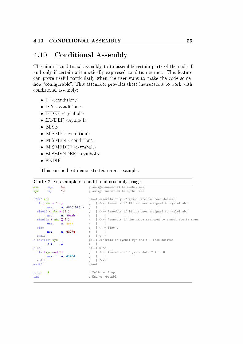
4.10 Conditional Assembly
The aim of conditional assembly to to assemble certain parts of the code ifand only if certain arithmetically expressed condition is met. This featurecan prove useful particularly when the user want to make the code some-how �con�gurable�. This assembler provides these instructions to work withconditional assembly:
• IF <condition>
• IFN <condition>
• IFDEF <symbol>
• IFNDEF <symbol>
• ELSE
• ELSEIF <condition>
• ELSEIFN <condition>
• ELSEIFDEF <symbol>
• ELSEIFNDEF <symbol>
• ENDIF
This can be best demonstrated on an example:
Code 7 An example of conditional assembly usageabc equ 16 ; Assign number 14 to symbol abc
xyz equ 10 ; Assign number 10 to symbol abc
ifdef abc ;<--+ Assemble only if symbol abc has been defined
if ( abc = 13 ) ; | <--+ Assemble if 13 has been assigned to symbol abc
mov a, #01010101b ; | |
elseif ( abc = 14 ) ; | <--+ Assemble if 14 has been assigned to symbol abc
mov a, #0aah ; | |
elseifn ( abc % 2 ) ; | <--+ Assemble if the value assigned to symbol abc is even
mov a, #abc ; | |
else ; | <--+ Else ..
mov a, #377q ; | |
endif ; | <--+
elseifndef xyz ;<--+ Assemble if symbol xyz has NOT been defined
clr A ; |
else ;<--+ Else ...
ifn (xyz mod 2) ; | <--+ Assemble if ( yxz modulo 2 ) is 0
mov a, #128d ; | |
endif ; | <--+
endif ;<--+
sjmp $ ; Infinite loop
end ; End of assembly

56 CHAPTER 4. BUILD-IN MACRO-ASSEMBLER
4.11 Macro Processing
Macro is a sequence of instructions which can be expanded anywhere in thecode and for any number of times. That may reduce necessity of repeatingcode fragments as well as source code size and make the solved task easierto comprehend and solve. Unlike subprograms macros do not add extrarun-time overhead and repeating usage of macros may signi�cantly increasesize of the resulting machine code. Macros supported by this assembler aredivided to named and unnamed ones.
MACRO De�ne a new named macroREPT De�ne a new unnamed macro and expand it right away for the speci�ed number of timesTIMES Exactly the same as �REPT�ENDM End of macro de�nition
Table 4.8: Directives directly related to macros
This can be well demonstrated on examples:
Code 8 An exaple of REPT directiverept 3 ; Repeat the code 3 times
mov a, p0
cpl a
mov p1, a
endm
; This is the same as if you wrote this:
mov a, p0
cpl a
mov p1, a
mov a, p0
cpl a
mov p1, a
mov a, p0
cpl a
mov p1, a

4.11. MACRO PROCESSING 57
Code 9 An exaple of simple named macroabc macro ; Define named macro ``abc''
mov a, p0
cpl a
mov p1, a
endm
abc ; Expand macro ``abc'' here
abc ; Expand macro ``abc'' here
; This is the same as if you wrote this:
mov a, p0
cpl a
mov p1, a
mov a, p0
cpl a
mov p1, a
Code 10 An exaple of named macro with two parameters; Define macro named as ``xyz'' with 2 mandatory parameters
xyz macro foo, bar
mov foo, #10h
cpl bar
endm
xyz a, c ; Expand macro ``xyz'' here
xyz p0, p1.0 ; Expand macro ``xyz'' here
; This is the same as if you wrote this:
; xyz a, c
mov a, #10h
cpl c
; xyz p0, p1.0
mov p0, #10h
cpl p1.0
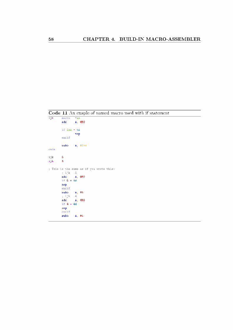
58 CHAPTER 4. BUILD-IN MACRO-ASSEMBLER
Code 11 An exaple of named macro used with if statementijk macro foo
add A, @R0
if foo = 4d
nop
endif
subb A, #foo
endm
ijk 5
ijk 4
; This is the same as if you wrote this:
; ijk 5
add A, @R0
if 5 = 4d
nop
endif
subb A, #5
; ijk 4
add A, @R0
if 4 = 4d
nop
endif
subb A, #4

4.11. MACRO PROCESSING 59
Code 12 An exaple of nested macros; Suppose we have these macros:
abc macro
mov a, p0
cpl a
mov p1, a
endm
ijk macro foo
add A, @R0
if foo = 4d
nop
endif
subb A, #foo
endm
xyz macro foo, bar
ijk foo
ijk bar
abc
endm
; And we expand ``xyz'' like this:
xyz 4, 5
; Then we get this result:
; ijk 4
add A, @R0
nop ; <-- Note this
subb A, #4
; ijk 5
add A, @R0
subb A, #5
; abc
mov a, p0
cpl a
mov p1, a
Code 13 An exaple of nested macros, which will not workabc macro
; Unnamed macro cannot be contained inside a named one
times 2
mov a, p0
cpl a
mov p1, a
endm
endm

60 CHAPTER 4. BUILD-IN MACRO-ASSEMBLER
4.12 Reserved keywords
Table 4.9: Special instruction operands
$ Location counterA AccumulatorAB A/B register pairC Carry �ag (in PSW register)DPTR Data pointerPC Program counterR0..R7 Registers
Table 4.10: Instruction mnemonics
ACALL ADD ADDC AJMP ANL CJNE CLR CPL DADEC DIV DJNZ INC JB JBC JC JMP JNBJNZ SJMP JNC CALL JZ LCALL LJMP MOV MOVCMOVX MUL NOP ORL POP PUSH RET RETI RLRLC RR RRC SETB SUBB SWAP XCH XCHD XRL
Table 4.11: Directives
BIT BSEG BYTE CODE CSEGDATA DB DBIT DS DSEGDW ELSE ELSEIF ELSEIFDEF ELSEIFNELSEIFNDEF END ENDIF ENDM EQUFLAG IDATA IF IFDEF IFNIFNDEF INCLUDE ISEG LIST MACRONAME NOLIST ORG REPT SETSKIP TIMES USING XDATA XSEG
Table 4.12: Expression operators
AND EQ GE GT HIGHLE LOW LT MOD NENOT OR SHL SHR XOR
Table 4.13: Assembler controls
DA DATE EJ EJECTLI LIST NOLI NOLISTNOMACROSFIRST NOMO NOMOD NOMOD51NOOBJECT NOPAGING NOPI NOPRINTNOSB NOSYMBOLS OBJECT PAGELENGTHPAGEWIDTH PAGING PI PLPRINT PW SB SYMBOLSTITLE TT

4.13. COMPATIBILITY WITH ASEM-51 61
4.13 Compatibility with ASEM-51
Not yet speci�ed.
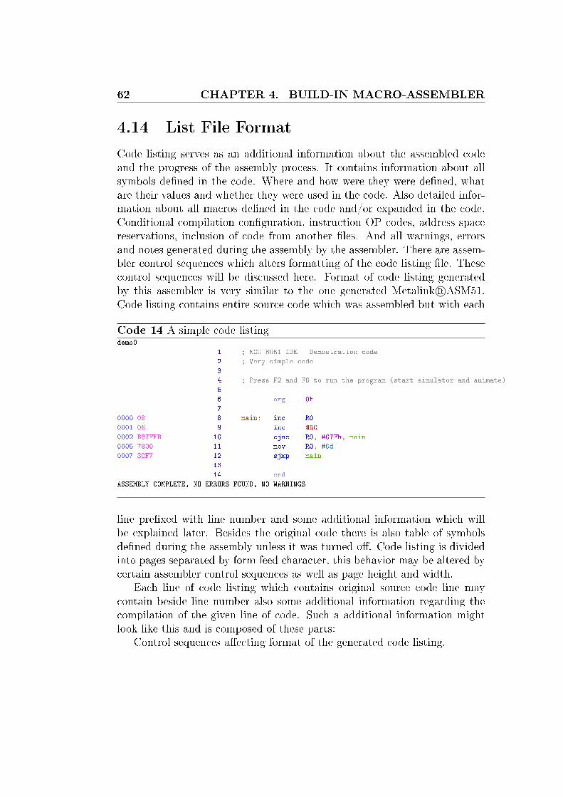
62 CHAPTER 4. BUILD-IN MACRO-ASSEMBLER
4.14 List File Format
Code listing serves as an additional information about the assembled codeand the progress of the assembly process. It contains information about allsymbols de�ned in the code. Where and how were they were de�ned, whatare their values and whether they were used in the code. Also detailed infor-mation about all macros de�ned in the code and/or expanded in the code.Conditional compilation con�guration, instruction OP codes, address spacereservations, inclusion of code from another �les. And all warnings, errorsand notes generated during the assembly by the assembler. There are assem-bler control sequences which alters formatting of the code listing �le. Thesecontrol sequences will be discussed here. Format of code listing generatedby this assembler is very similar to the one generated Metalink R©ASM51.Code listing contains entire source code which was assembled but with each
Code 14 A simple code listingdemo0 PAGE 1
1 ; MCU 8051 IDE - Demostration code
2 ; Very simple code
3
4 ; Press F2 and F6 to run the program (start simulator and animate)
5
6 org 0h
7
0000 08 8 main: inc R0
0001 06 9 inc @R0
0002 B87FFB 10 cjne R0, #07Fh, main
0005 7800 11 mov R0, #0d
0007 80F7 12 sjmp main
13
14 end
ASSEMBLY COMPLETE, NO ERRORS FOUND, NO WARNINGS
line pre�xed with line number and some additional information which willbe explained later. Besides the original code there is also table of symbolsde�ned during the assembly unless it was turned o�. Code listing is dividedinto pages separated by form feed character, this behavior may be altered bycertain assembler control sequences as well as page height and width.
Each line of code listing which contains original source code line maycontain beside line number also some additional information regarding thecompilation of the given line of code. Such a additional information mightlook like this and is composed of these parts:
Control sequences a�ecting format of the generated code listing.
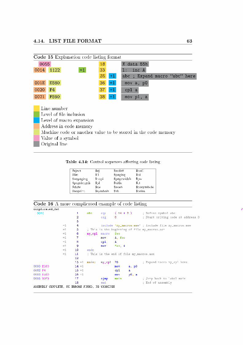
4.14. LIST FILE FORMAT 63
Code 15 Explanation code listing format
0055 18 X data 55h
0014 1122 =1 33 l: inc A
35 +1 abc ; Expand macro �abc� here
001E E580 36 +1 mov a, p0
0020 F4 37 +1 cpl a
0021 F590 38 +1 mov p1, a
X Line numberX Level of �le inclusionX Level of macro expansionX Address in code memoryX Machine code or another value to be stored in the code memoryX Value of a symbolX Original line
Table 4.14: Control sequences a�ecting code listing
$eject $ej $nolist $noli$list $li $paging $pi$nopaging $nopi $pagewidth $pw$pagelength $pl $title $tt$date $da $nosb $nosymbols$noprint $symbols $sb $print
Code 16 A more complicated example of code listingcomplicated_lst PAGE 1
001C 1 abc equ ( 14 * 2 ) ; Define symbol abc
2 org 0 ; Start writing code at address 0
3
=1 4 include 'my_macros.asm' ; Include file my_macros.asm
=1 5 ; This is the beginning of file my_macros.asm
=1 6 my_cpl macro foo
=1 7 mov A, foo
=1 8 cpl A
=1 9 mov foo, A
=1 10 endm
=1 11 ; This is the end of file my_macros.asm
12
13 +1 main: my_cpl P0 ; Expand macro my_cpl here
0000 E580 14 +1 mov a, p0
0002 F4 15 +1 cpl a
0003 F580 16 +1 mov p0, a
0005 80F9 17 sjmp main ; Jump back to label main
18 end ; End of assembly
ASSEMBLY COMPLETE, NO ERRORS FOUND, NO WARNINGS
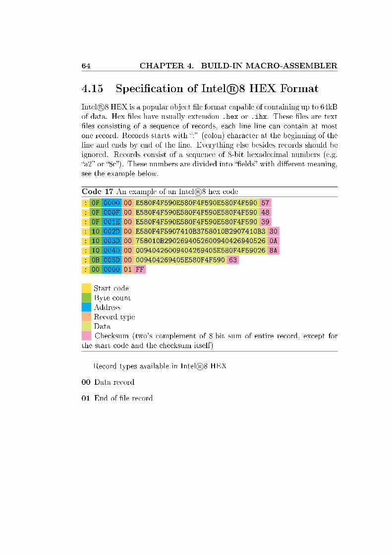
64 CHAPTER 4. BUILD-IN MACRO-ASSEMBLER
4.15 Speci�cation of Intel R©8 HEX Format
Intel R©8 HEX is a popular object �le format capable of containing up to 64kBof data. Hex �les have usually extension .hex or .ihx. These �les are text�les consisting of a sequence of records, each line line can contain at mostone record. Records starts with �:� (colon) character at the beginning of theline and ends by end of the line. Everything else besides records should beignored. Records consist of a sequence of 8-bit hexadecimal numbers (e.g.�a2� or �8c�). These numbers are divided into ��elds� with di�erent meaning,see the example below.
Code 17 An example of an Intel R©8 hex code
: 0F 0000 00 E580F4F590E580F4F590E580F4F590 57
: 0F 000F 00 E580F4F590E580F4F590E580F4F590 48
: 0F 001E 00 E580F4F590E580F4F590E580F4F590 39
: 10 002D 00 E580F4F5907410B3758010B2907410B3 30
: 10 003D 00 758010B2902694052600940426940526 0A
: 10 004D 00 00940426009404269405E580F4F59026 8A
: 0B 005D 00 009404269405E580F4F590 63
: 00 0000 01 FF
X Start codeX Byte countX AddressX Record typeX DataX Checksum (two's complement of 8-bit sum of entire record, except forthe start code and the checksum itself)
Record types available in Intel R©8 HEX
00 Data record
01 End of �le record

65
Chapter 5
Disassembler
Disassembler is a tool intended to generate assembly language code froman object �le. In other words it has certain level of capability of reversingthe assembly process and regaining the original source code from any objectcode. But there are some restriction to that capability and the whole thingis not so simple after all. So let's discuss disassembly process deeper. InMCU 8051 IDE you can invoke disassembler from the main menu �MainMenu� → �Tools� → �Disassemble�.
A simple example of a code generated by disassembler
Original code:org 0h ; Start at address 0x00
main: inc R0 ; Increment R0
inc @R0
cjne R0, #07Fh, main
mov R0, #0d ;
sjmp main ; Jump back to label main
end ; End of assembly
Code generated by disassemblerORG 0h
label0: inc R0
inc @R0
cjne R0, #7Fh, label0
mov R0, #0h
sjmp label0
END
As you can see from the example above, the code generated by disassem-bler is the same as the original code. But of course original symbol nameshave vanished as well as comments, indentation and other tiny details whichcannot be determined from the object code. This is caused by the simple factthat the object code contains only the machine code. It contains no infor-mation regarding how exactly the original code looked like. Just instructionswith their operands and data directly written to the code memory by �DB�and �DW� directives. And here we are getting to the real problem whichemerges every time when you try to disassemble �not exactly a simple� code.
8051 instructions comprises of 1, 2 or 3 bytes, the �rst byte determinateswhat instruction are we dealing with and so what is its length in bytes. But

66 CHAPTER 5. DISASSEMBLER
if the original code contained directives �DB� or �DW� then the disassembler�thinks� that these values are instructions too. If the disassembler considera arbitrary value given by �DB� or �DW� instruction to be an instruction, itdeterminates its length according to its OP code (the 1st argument to the di-rective). And so it takes 0, 1 or 2 bytes next and interprets them as operandsto that instruction. Then when it encounters a real instruction OP code itmight think of it as another operand to something and so misinterpret it.Then you might end up with a code that is completely di�erent from theoriginal code and makes no sense at all to human. But if you reassemblesuch a �non sense� code with disabled peep hole optimization you must getthe original object code back, and its functionality must not be changed.Even if the code seems to be absolutely non sense. In that case I stronglyrecommend to use another disassembler than is the built-in one. Consider forexample D52 http://www.8052.com/users/disasm/. The built-in diassem-bler is provided just for �completeness�, but its suitability for a real reverseengineering is highly questionable.
A simple example of a BADLY generated code by disassembler
Original code:org 0h ; Start at address 0x00
main: inc R0 ; Increment R0
inc @R0
jmp cont
db 'some stringx'
cont: cjne R0, #07Fh, main
mov R0, #0d ;
sjmp main ; Jump back to label main
end ; End of assembly
Code generated by disassemblerlabel0 CODE 11h
ORG 0h
label1: inc R0
inc @R0
ljmp label0
jmp @A+DPTR
xrl A, R7
xrl A, R5
xrl A, 20h
jmp @A+DPTR
mov A, #72h
xrl A, R1
xrl A, R6
xrl A, @R1
mov R0, #0B8h
mov R7, #0ECh
mov R0, #0h
sjmp label1
END
67
Chapter 6
MCU simulator
6.1 Short introduction
The MCU simulator is a tool designed to mimics behavior of a real MCU asmuch as possible. But it can have certain limitations, the most expectablelimitation is of course the speed of simulation. This simulator is very slow,but o�ers some extra features.
6.2 Modes of simulation
There are 4 modes of simulation:
Step Execute exactly one intruction, no matter how many machine cycles itwill take. This does not apply for macro-instruction, in that case eachinstruction of the macro is executed separately.
Step over Execute as many instructions as possible until simulator cursorchanges its location from one line of source code to another.
Animate Do the same as �step� but in a loop, one after another untilstopped by a waring condition or user request.
Run This is generally the same as �animate�, but much faster, because GUIis not updated so o�ten as in the �animate� mode.
(Step Back) Take back the last performed step. There is limited numberof step which can be taken back.
Virual HW can be enabled or disabled, it signi�cantly a�ects speed of thesimulation. Of course simulation is slower when virtual HW is on.
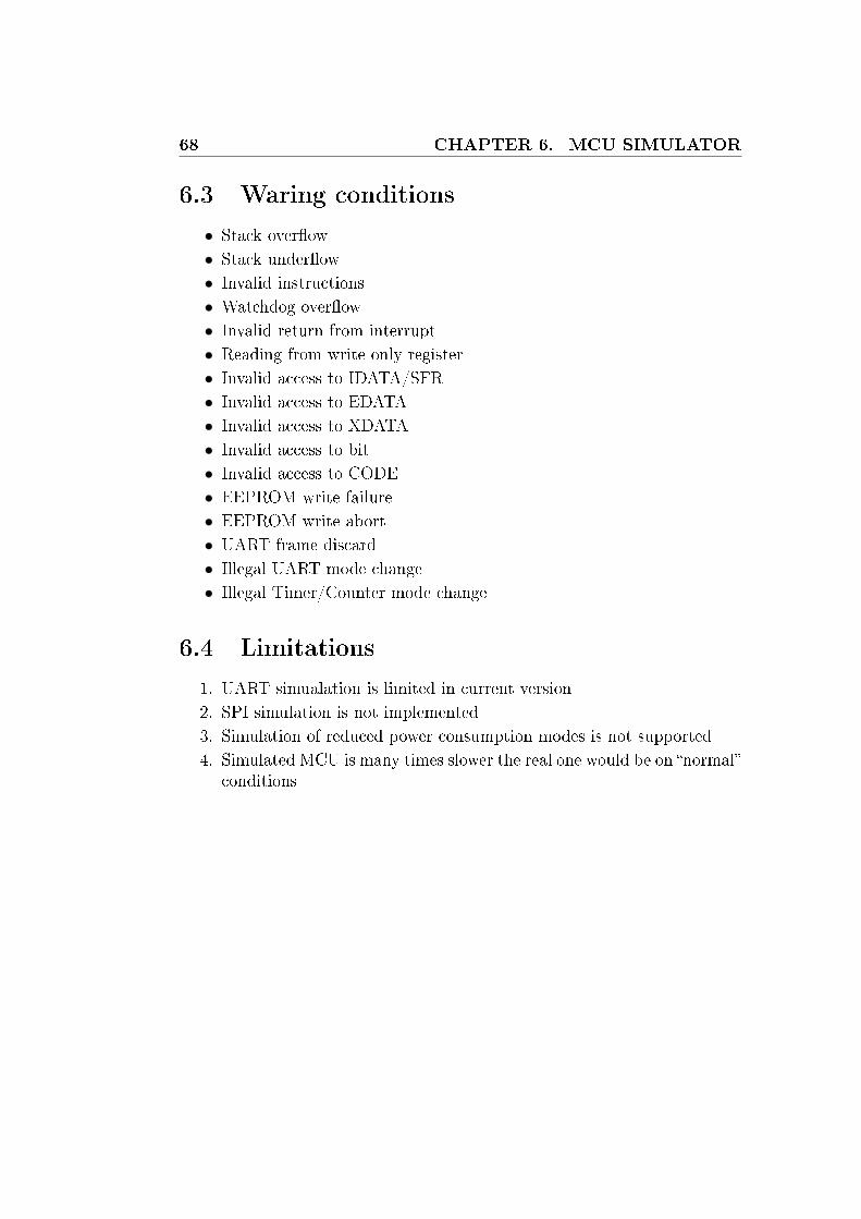
68 CHAPTER 6. MCU SIMULATOR
6.3 Waring conditions
• Stack over�ow
• Stack under�ow
• Invalid instructions
• Watchdog over�ow
• Invalid return from interrupt
• Reading from write only register
• Invalid access to IDATA/SFR
• Invalid access to EDATA
• Invalid access to XDATA
• Invalid access to bit
• Invalid access to CODE
• EEPROM write failure
• EEPROM write abort
• UART frame discard
• Illegal UART mode change
• Illegal Timer/Counter mode change
6.4 Limitations
1. UART simualation is limited in current version
2. SPI simulation is not implemented
3. Simulation of reduced power consumption modes is not supported
4. Simulated MCU is many times slower the real one would be on �normal�conditions

6.5. VIRTUAL HARDWARE 69
6.5 Virtual hardware
MCU 8051 IDE simulator is also equipped with a few simulated simple hard-ware devices, which can be connected to the simulated MCU. These virtualhardware components are intended primarily to o�er a better insight intoprograms interacting with things like LEDs or keys.
All wires connected to speci�c GPIO lines are colored according to thevoltage level present on them, colors are the same as for graph in the bot-tom panel (GREEN == log. 0; RED == log. 1; GRAY == not connected,etc.) Each of these virtual HW components has its own con�guration menuand help text available trough that menu. Con�guration can be saved to a�le with extension .vhc, and can be loaded from that �le later. The con-�guration menu is accessible trough the button with this icon: � �. The� ON �/� OFF � button enables or disables entire subsystem of virtual hardware sim-ulation including the graph of GPIO wires on the bottom panel.
6.5.1 DS1620 temperature sensor
Figure 6.1: DS1620 simulatorand its log window
Simulates DALLAS R©DS1620 thermometer alongwith its 3-wire communication interface. Tem-perature which this simulated device should mea-sure can be set by used on the scale in DS1620simulator window. All internal registers of thedevice are displayed to the user and are modi-�able by the user, current con�guration of thedevice simulator including DS1620 non-volatileregisters can be save into a �le for further use. Allcommunications with the simulated MCU and in-ternal operation of the simulated thermometerare displayed in simulator log, log can be accessed via the DS1620 simulator con-�guration menu (� �).
6.5.2 File interface
Figure 6.2: PALE I/O interface
This tool can automatically switch statesof GPIO lines of the simulated accord-ing to certain de�nition �le and it canalso record all changes occurring on arbi-trary GPIO line to a speci�ed output �le.This function can be particularly usefulwhen you are dealing with a 8051 pro-
gram which extensively works with I/O ports.

70 CHAPTER 6. MCU SIMULATOR
6.5.3 LED Panel
Figure 6.3: LED Panel
This is the simplest example of such avirtual hardware component. A simplepanel consisting of 8 independent LEDswith common anode. Each LED can beconnected to separate port and pin andreact immediately to any change in volt-age level on that line. Connections withthe µC are made with combo boxes on thebottom side of the panel.
6.5.4 Single LED Display
Figure 6.4: LED Display
Single 8 segment LED display with onedecimal point. Common electrode for theLEDs can be con�gured as well as the LEDcolor. Each LED can be independentlyconnected to any port and pin and reactsimmediately to any change in voltage levelon that pin. Common electrode is stati-cally connected to either common groundor Vcc.
6.5.5 Multiplexed LED Display
Figure 6.5: M LED Display
4 digits LED displays indented for run in mul-tiplexed mode, LEDs are fading with con�g-urable delay. Each digit has its own commonelectrode which polarity is con�gurable, thiscommon electrode is connected to output froman inverter or transistor. There are four colorshades for each LED segment, one for inactive,one for active, one for fast blinking and onefor segment which was recently dimmed, thatmakes it possible to see an image which wouldprobably appear on a real display when viewed just by the eye. Unit for the fadinginterval is one instruction cycle.

6.5. VIRTUAL HARDWARE 71
6.5.6 LED Matrix
Figure 6.6: LED Matrix
Simple one color 8 x 8 LED matrix indented forrun in multiplexed mode, LEDs are fading withcon�gurable delay. Everything here is the sameas for the Multiplexed LED Display, except forone thing, mapping. Mapping can be set to row,column or random, which is default. Row map-ping means that row which has been activatedright now immediately forgets which LEDs wereshinning last time and which were not. Columnmapping is the same but for columns and ran-dom mapping means that each LED will dim af-
ter speci�ed interval and not when its row or column is activated. So in randommapping you have to wait until all LEDs are gray before you can draw a new imagewithout being a�ected by the last one.
6.5.7 Matrix Keypad
Figure 6.7: Matrix Keypad
4 x 4 Matrix keypad, each row and col-umn can be connected to any GPIOline. Connections with the µC aremade with the combo boxes. Keyscan be con�gured to behave as radiobutton1. Note that this tool can bealso used to interconnect some portpins together statically, like wires ina bread board. Any key press takese�ect immediately in all other vir-tual hardware components connectedto the same line.
1Radio buttons that means that one one key can be pressed at the time and when youpress another key, the originally pressed key will return back to non pressed state
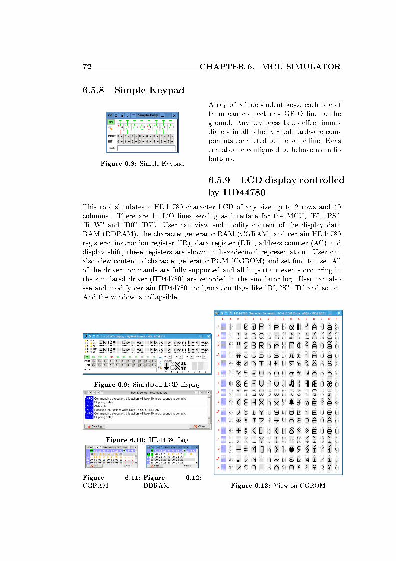
72 CHAPTER 6. MCU SIMULATOR
6.5.8 Simple Keypad
Figure 6.8: Simple Keypad
Array of 8 independent keys, each one ofthem can connect any GPIO line to theground. Any key press takes e�ect imme-diately in all other virtual hardware com-ponents connected to the same line. Keyscan also be con�gured to behave as radiobuttons.
6.5.9 LCD display controlled
by HD44780
This tool simulates a HD44780 character LCD of any size up to 2 rows and 40columns. There are 11 I/O lines serving as interface for the MCU, �E�, �RS�,�R/W� and �D0�..�D7�. User can view end modify content of the display dataRAM (DDRAM), the character generator RAM (CGRAM) and certain HD44780registers: instruction register (IR), data register (DR), address counter (AC) anddisplay shift, these registers are shown in hexadecimal representation. User canalso view content of character generator ROM (CGROM) and set font to use. Allof the driver commands are fully supported and all important events occurring inthe simulated driver (HD44780) are recorded in the simulator log. User can alsosee and modify certain HD44780 con�guration �ags like �B�, �S�, �D� and so on.And the window is collapsible.
Figure 6.9: Simulated LCD display
Figure 6.10: HD44780 Log
Figure 6.11:
CGRAMFigure 6.12:
DDRAM Figure 6.13: View on CGROM

73
Chapter 7
Writing hardware tool control
plug-ins
7.1 Foreword
Figure 7.1: An example ofHW control plug-in
It is not surprising that IDE for micro-controllersshould be capable of inter-operation with certain hard-ware tools. MCU 8051 IDE has tool named HW plug-ins manager which is responsible for loading and man-aging plug-ins written in order to to �integrate� exit-ing hardware tools into this IDE. With this feature ev-ery author of a 8051 programmer, ICD, ICE etc. whoknows Tcl/Tk language has the opportunity to makehis or her own tool working in direct cooperation withthe IDE. These plug-ins have to be written at least par-tially in the TCL language and use the Tk library alongwith API of MCU 8051 IDE. But that doesn't meanthat they should be written entirely in Tcl/Tk. On thecontrary I would encourage usage of another languagesfor example SSP89S, also a part of MCU 8051 IDEproject, is written almost completely in C++/Qt4, butonly a �small� piece of the software is written in Tcl/Tk.Tcl/Tk can easily inter-operate with C and C++, alsoit is possible to run arbitrary separate process from in-side of Tcl/Tk program and control it vie for exampleTCP sockets or its stdin/stdout or something else.

74CHAPTER 7. WRITING HARDWARE TOOL CONTROL
PLUG-INS
7.2 How to write your own plug-in
At �rst take these steps:
1. Create the plug-in directory
On POSIX system the plug-in directory have to be placed in�/usr/share/mcu8051ide/hwplugins�, on Microsoft R©Windows R©the directoryis �<YourInstallationDirectory>\hwplugins�. The plug-in directory mustcarry the name of your plug-in, where spaces are replaced with �_� (un-derscore) characters. For example suppose you want to create a plug-innamed as �My First Plug-in v1.0�, then your plug-in directory directory is�My_First_Plug-in_v1.0�.
2. Create the plug-in initialization �le
Plug-in initialization �le tells the IDE that there is some plug-in at all. The�le contains basic initialization of the plug-in environment and must followcertain rules. The �le name must also follow name of the plug-in in the sameway as the plug-in directory. But the initialization �le have to be placed indirectory hwplugins. And must have extension .tcl! For example consideragain our �My First Plug-in v1.0� plug-in, as we mentioned before. Theplug-in directory is: �/usr/share/mcu8051ide/hwplugins/My_First_Plug-in_v1.0� then the initialization �le is:�/usr/share/mcu8051ide/hwplugins/My_First_Plug-in_v1.0.tcl�.
3. De�ne mandatory variables
set AUTHOR "<your name>" ;# e.g. "Homer Simpson"
set EMAIL "<[email protected]>" ;# e.g. "[email protected]"
set P_VERSION "<version_of_your_plug-in>" ;# e.g. "1.2.3" or "0.9"
set MIN_IDE_VER "1.1" ;# Mimimal required version of MCU 8051 IDE
4. De�ne mandatory functions
# Free resources occupied by this plugin
proc dispose {} { ... }
# Initialize the plug-in
proc init {main_frame current_namespace directory} { ... }
# Restore previous session
proc restore_session {session_data} { ... }
# Save plug-in session
proc save_session {} { ...; return <String> }
# Is plugin busy ?
proc is_busy {} { ...; return <BooleanValue> }

7.3. USING MCU 8051 IDE API 75
�...� means any code you want there. See �/usr/share/mcu8051ide/hwplugins/plug-in_template.txt� or �<YourInstallationDirectory>\hwplugins\plug-in_template.txt�for more details and for a template for such �le.
When you have these steps completed you have prepared basic environmentfor the plug-in. Then the �HW plug-ins manager� in the right panel in IDE'sGUI should now recognize your plug-in and be able to attempt to load it. If itis not so, then there is de�nitely something wrong. Any other �les which yourplug-in consist of and just whatever you want there should be placed in your plug-in directory (1). And the initialization �le should do nothing else than sourcesome real plug-in's �le(s) and call appropriate functions inside them. One moreimportant thing, the plug-in runs it dynamically assigned namespace. Take itinto account, otherwise your plug-in wont work! Function �init� takes the name ofthis namespace in parameter �current_namespace�. So as you can see, it's quiteeasy you have just to de�ne 4 variables and 5 functions and you can interface withthe IDE.
7.3 Using MCU 8051 IDE API
You can used any part the API you want, but the entire IDE's API is wast andmay change in future without notice. So there is special API dedicated to use inhardware control plug-ins, it is located in �::HwManager� namespace and consistsof merely 10 simple functions. This API is available since version 1.4. Here is thelist of its functions:
## Check whether there is some project opened in the IDE
# @return Bool - 1 == Yes, there is; 0 == No there is not
proc is_project_opened {}
## Check whether MCU simulator is engaged
# @return Bool - 0 == 1 == Yes, it is; No it is not (or no project is opened)
proc is_simulator_engaged {}
## Get full name of file which is currently displayed in the source code editor
# @return String - Full file name including path or empty string in case there is no project opened
proc get_current_file {}
## Get full name of file which has been chosen as the project main file
# @return String - Full file name or empty string
proc get_project_main_file {}
## Get path the directory of currently active project
# @return String - Directory path or empty string in case there is no project opened
proc get_project_dir {}
## Get name of the current project
# @return String - Name of the current project or empty string in case there is no project opened
proc get_project_name {}
## Initiate compilation if at least one of the source files was modified
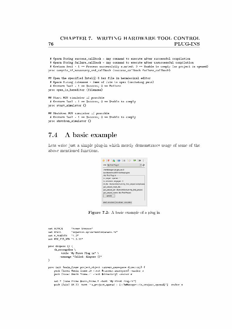
76CHAPTER 7. WRITING HARDWARE TOOL CONTROL
PLUG-INS
# @parm String success_callback - Any command to execute after successful compilation
# @parm String failure_callback - Any command to execute after unsuccessful compilation
# @return Bool - 1 == Process successfully started; 0 == Unable to comply (no project is opened)
proc compile_if_nessesary_and_callback {success_callback failure_callback}
## Open the specified Intel R© 8 hex file in hexadecimal editor
# @parm String filename - Name of file to open (including path)
# @return Bool - 1 == Success; 0 == Failure
proc open_in_hexeditor {filename}
## Start MCU simulator if possible
# @return Bool - 1 == Success; 0 == Unable to comply
proc start_simulator {}
## Shutdown MCU simulator if possible
# @return Bool - 1 == Success; 0 == Unable to comply
proc shutdown_simulator {}
7.4 A basic example
Lets write just a simple plug-in which merely demonstrates usage of some of theabove mentioned functions.
Figure 7.2: A basic example of a plug-in
set AUTHOR "Homer Simpson"
set EMAIL "[email protected]"
set P_VERSION "1.0"
set MIN_IDE_VER "1.3.11"
proc dispose {} {
tk_messageBox \
-title "My First Plug-in" \
-message "Called: dispose {}"
}
proc init {main_frame project_object current_namespace directory} {
pack [label $main_frame.l0 -text $current_namespace] -anchor w
pack [label $main_frame.l1 -text $directory] -anchor w
set f [labelframe $main_frame.f -text "My First Plug-in"]
pack [label $f.l0 -text "is_project_opened : [::HwManager::is_project_opened]"] -anchor w
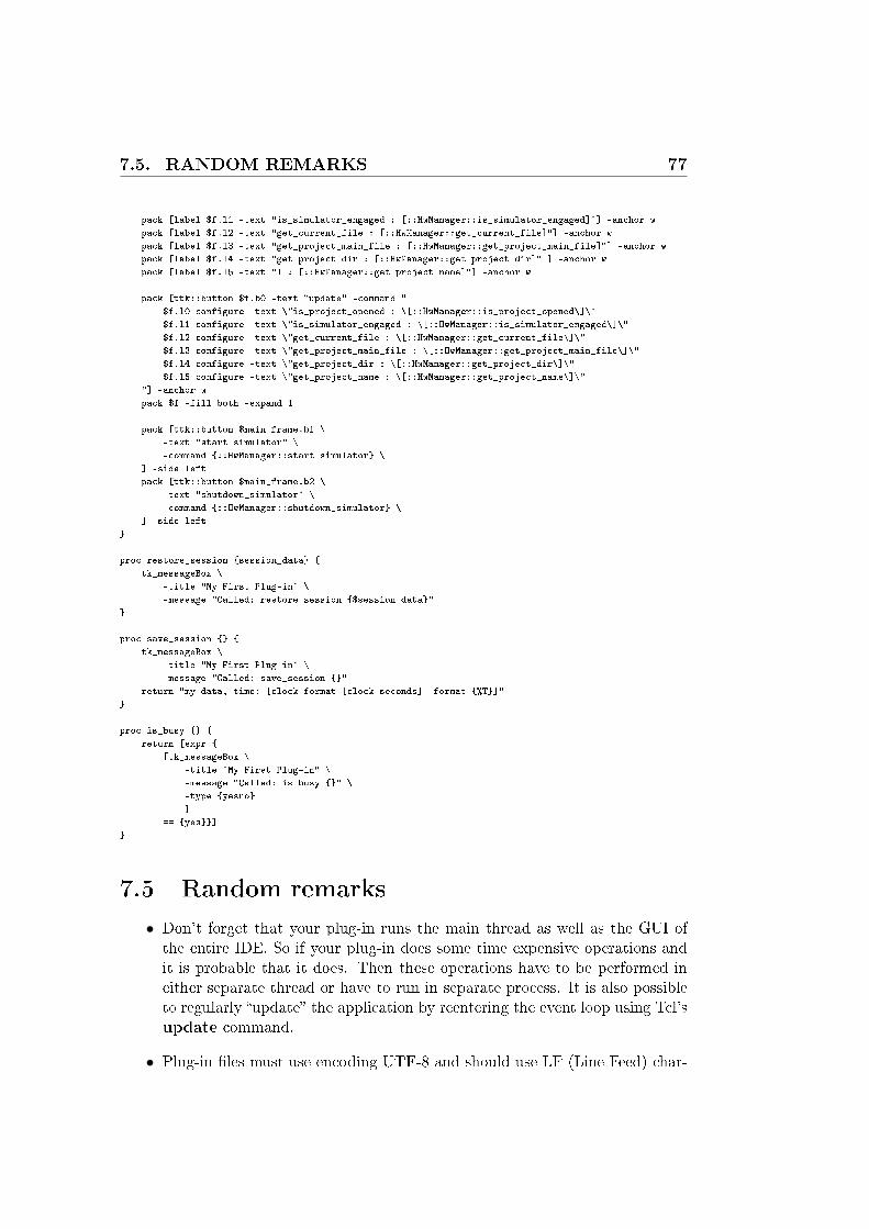
7.5. RANDOM REMARKS 77
pack [label $f.l1 -text "is_simulator_engaged : [::HwManager::is_simulator_engaged]"] -anchor w
pack [label $f.l2 -text "get_current_file : [::HwManager::get_current_file]"] -anchor w
pack [label $f.l3 -text "get_project_main_file : [::HwManager::get_project_main_file]"] -anchor w
pack [label $f.l4 -text "get_project_dir : [::HwManager::get_project_dir]" ] -anchor w
pack [label $f.l5 -text "l : [::HwManager::get_project_name]"] -anchor w
pack [ttk::button $f.b0 -text "update" -command "
$f.l0 configure -text \"is_project_opened : \[::HwManager::is_project_opened\]\"
$f.l1 configure -text \"is_simulator_engaged : \[::HwManager::is_simulator_engaged\]\"
$f.l2 configure -text \"get_current_file : \[::HwManager::get_current_file\]\"
$f.l3 configure -text \"get_project_main_file : \[::HwManager::get_project_main_file\]\"
$f.l4 configure -text \"get_project_dir : \[::HwManager::get_project_dir\]\"
$f.l5 configure -text \"get_project_name : \[::HwManager::get_project_name\]\"
"] -anchor w
pack $f -fill both -expand 1
pack [ttk::button $main_frame.b1 \
-text "start_simulator" \
-command {::HwManager::start_simulator} \
] -side left
pack [ttk::button $main_frame.b2 \
-text "shutdown_simulator" \
-command {::HwManager::shutdown_simulator} \
] -side left
}
proc restore_session {session_data} {
tk_messageBox \
-title "My First Plug-in" \
-message "Called: restore_session {$session_data}"
}
proc save_session {} {
tk_messageBox \
-title "My First Plug-in" \
-message "Called: save_session {}"
return "my data, time: [clock format [clock seconds] -format {%T}]"
}
proc is_busy {} {
return [expr {
[tk_messageBox \
-title "My First Plug-in" \
-message "Called: is_busy {}" \
-type {yesno}
]
== {yes}}]
}
7.5 Random remarks
• Don't forget that your plug-in runs the main thread as well as the GUI ofthe entire IDE. So if your plug-in does some time expensive operations andit is probable that it does. Then these operations have to be performed ineither separate thread or have to run in separate process. It is also possibleto regularly �update� the application by reentering the event loop using Tcl'supdate command.
• Plug-in �les must use encoding UTF-8 and should use LF (Line Feed) char-

78CHAPTER 7. WRITING HARDWARE TOOL CONTROL
PLUG-INS
acter as line end delimiter. In other words Unix line termination sequence.
• Although it is possible to name the plug-in directory in any way what your OSaccept. It is generally a good idea to follow the mentioned recommendation.At least the name of the initialization �le have to follow the mentionedrecommendation.
• Plug-ins have unrestricted access to the entire application. So they shouldbe written carefully, because plug-ins can theoretically crash down the entireIDE.
• Program errors which occurs during loading or unloading of a plug-in arereported via a special dialog. In this dialog plug-in author and his or heremail address are mentioned.
• The above mentioned API provided by �::HwManager� is just a facade1.Before version 1.4 plug-ins must have had to be written to access directlythe functionality currently hidden behind �::HwManager�, so it was muchmore complicated.
• Each instance of a hardware plug-ins manager is bond to its project. Butactual plug-ins don't have to be. That's the reason why there is function�::HwManager::is_project_opened �. All functions inside the above men-tioned API (::HwManager::*) works with the current project, not neces-saryly with the project which is the HW manager bond with.
1A design pattern as described in the GOF book
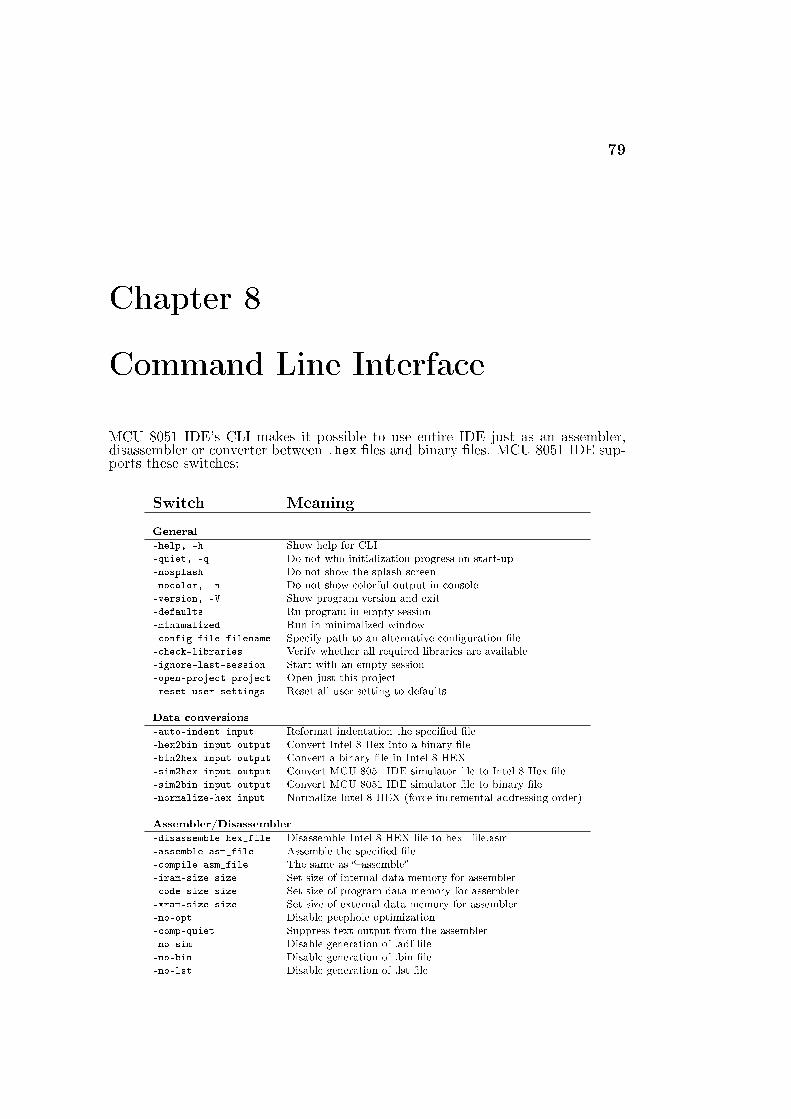
79
Chapter 8
Command Line Interface
MCU 8051 IDE's CLI makes it possible to use entire IDE just as an assembler,disassembler or converter between .hex �les and binary �les. MCU 8051 IDE sup-ports these switches:
Switch Meaning
General
�help, -h Show help for CLI�quiet, -q Do not who initialization progress on start-up�nosplash Do not show the splash screen�nocolor, -n Do not show colorful output in console�version, -V Show program version and exit�defaults Ru program in empty session�minimalized Run in minimalized window�config-file filename Specify path to an alternative con�guration �le�check-libraries Verify whether all required libraries are available�ignore-last-session Start with an empty session�open-project project Open just this project�reset-user-settings Reset all user setting to defaults
Data conversions
�auto-indent input Reformat indentation the speci�ed �le�hex2bin input output Convert Intel 8 Hex into a binary �le�bin2hex input output Convert a binary �le in Intel 8 HEX�sim2hex input output Convert MCU 8051 IDE simulator �le to Intel 8 Hex �le�sim2bin input output Convert MCU 8051 IDE simulator �le to binary �le�normalize-hex input Normalize Intel 8 HEX (force incremental addressing order)
Assembler/Disassembler
�disassemble hex_file Disassemble Intel 8 HEX �le to hex_�le.asm�assemble asm_file Assemble the speci�ed �le�compile asm_file The same as ��assemble��iram-size size Set size of internal data memory for assembler�code-size size Set size of program data memory for assembler�xram-size size Set size of external data memory for assembler�no-opt Disable peephole optimization�comp-quiet Suppress text output from the assembler�no-sim Disable generation of .adf �le�no-bin Disable generation of .bin �le�no-lst Disable generation of .lst �le
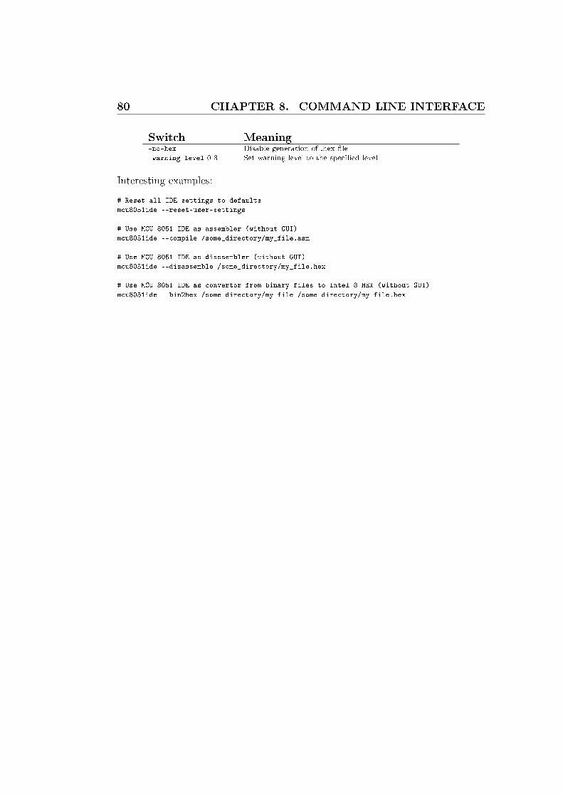
80 CHAPTER 8. COMMAND LINE INTERFACE
Switch Meaning�no-hex Disable generation of .hex �le�warning-level 0-3 Set warning level to the speci�ed level
Interesting examples:
# Reset all IDE settings to defaults
mcu8051ide --reset-user-settings
# Use MCU 8051 IDE as assembler (without GUI)
mcu8051ide --compile /some_directory/my_file.asm
# Use MCU 8051 IDE as disssembler (without GUI)
mcu8051ide --disassemble /some_directory/my_file.hex
# Use MCU 8051 IDE as convertor from binary files to Intel 8 HEX (without GUI)
mcu8051ide --bin2hex /some_directory/my_file /some_directory/my_file.hex
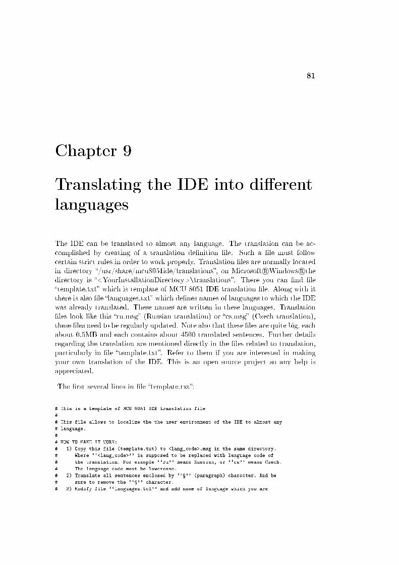
81
Chapter 9
Translating the IDE into di�erent
languages
The IDE can be translated to almost any language. The translation can be ac-complished by creating of a translation de�nition �le. Such a �le must followcertain strict rules in order to work properly. Translation �les are normally locatedin directory �/usr/share/mcu8051ide/translations�, on Microsoft R©Windows R©thedirectory is �<YourInstallationDirectory>\translations�. There you can �nd �le�template.txt� which is template of MCU 8051 IDE translation �le. Along with itthere is also �le �languages.txt� which de�nes names of languages to which the IDEwas already translated. These names are written in these languages. Translation�les look like this �ru.msg� (Russian translation) or �cs.msg� (Czech translation),these �les need to be regularly updated. Note also that these �les are quite big, eachabout 0.5MB and each contains about 4500 translated sentences. Further detailsregarding the translation are mentioned directly in the �les related to translation,particularly in �le �template.txt�. Refer to them if you are interested in makingyour own translation of the IDE. This is an open-source project so any help isappreciated.
The �rst several lines in �le �template.txt�:
# This is a template of MCU 8051 IDE translation file
#
# This file allows to localize the the user environment of the IDE to almost any
# language.
#
# HOW TO MAKE IT WORK:
# 1) Copy this file (template.txt) to <lang_code>.msg in the same directory.
# Where ``<lang_code>'' is supposed to be replaced with language code of
# the translation. For example ``ru'' means Russian, or ``cs'' means Czech.
# The language code must be lowercase.
# 2) Translate all sentences enclosed by ``�'' (paragraph) character. And be
# sure to remove the ``�'' character.
# 3) Modify file ``languages.tcl'' and add name of language which you are

82CHAPTER 9. TRANSLATING THE IDE INTO DIFFERENT
LANGUAGES
# making the translation for. Name should be specified in that language.
#
# IMPORTANT RULES FOR TRANSLATION:
# 1) Be aware of that this file is very sensitive.
# 2) Everything besides actual sentences for translation must not be modified
# in any way! Otherwise the file might cause serious program instability.
# 3) Escape sequences and all special characters must be preserved.
# 4) Sentences enclosed with ``"'' (double quote) character, can be translated
# into sentences with different length. But the same does not apply for
# sentences enclosed with ``{'' and ``}'' (curly brackets) characters,
# their lengths must stay preserved.
# 5) Do not translate ``$'' dollar symbol, it has a special meaning here, not
# related to currency.
# 6) Keep UTF-8 encoding and if possible, please keep also Unix line ends.
#
# NOTES:
# 1) `` ;# <-- NOT TRANSLATED YET'' is just a comment and can be removed at
# any time
# 2) Nothing is perfect ... if you find anything strange or not functional
# here, please report it as a regular bug.
# 3) Recommended syntax highlight pattern for this file is "Tcl/Tk"
# 4) Please don't hesitate to ask any questions.
#
# Thank you for your cooperation, which helps us make the software better!
#
A random piece of the translation de�nition �le template
mcset $l "Replace all" \
"�Replace all�" ;# <-- NOT TRANSLATED YET
mcset $l "Find next" \
"�Find next�" ;# <-- NOT TRANSLATED YET
mcset $l "Close" \
"�Close�" ;# <-- NOT TRANSLATED YET
mcset $l "Replace confirmation - %s" \
"�Replace confirmation - %s�" ;# <-- NOT TRANSLATED YET
mcset $l "Go to line" \
"�Go to line�" ;# <-- NOT TRANSLATED YET
mcset $l "Ok" \
"�Ok�" ;# <-- NOT TRANSLATED YET
mcset $l "Cancel" \
"�Cancel�" ;# <-- NOT TRANSLATED YET
mcset $l "Go to line - MCU 8051 IDE" \
"�Go to line - MCU 8051 IDE�" ;# <-- NOT TRANSLATED YET
mcset $l "Choose directory - MCU 8051 IDE" \
"�Choose directory - MCU 8051 IDE�" ;# <-- NOT TRANSLATED YET

83
Appendix A
License
MCU 8051 IDE and all its compo-nents is distributed under terms of GNUGPLv2.GNU GENERAL PUBLIC LICENSE
Version 2, June 1991
Copyright (C) 1989, 1991 Free Software Foundation, Inc.
675 Mass Ave, Cambridge, MA 02139, USA
Everyone is permitted to copy and distribute verbatim copies
of this license document, but changing it is not allowed.
Preamble
The licenses for most software are designed to take away your
freedom to share and change it. By contrast, the GNU General Public
License is intended to guarantee your freedom to share and change free
software--to make sure the software is free for all its users. This
General Public License applies to most of the Free Software
Foundations software and to any other program whose authors commit to
using it. (Some other Free Software Foundation software is covered by
the GNU Library General Public License instead.) You can apply it to
your programs, too.
When we speak of free software, we are referring to freedom, not
price. Our General Public Licenses are designed to make sure that you
have the freedom to distribute copies of free software (and charge for
this service if you wish), that you receive source code or can get it
if you want it, that you can change the software or use pieces of it
in new free programs; and that you know you can do these things.
To protect your rights, we need to make restrictions that forbid
anyone to deny you these rights or to ask you to surrender the rights.
These restrictions translate to certain responsibilities for you if you
distribute copies of the software, or if you modify it.
For example, if you distribute copies of such a program, whether
gratis or for a fee, you must give the recipients all the rights that
you have. You must make sure that they, too, receive or can get the
source code. And you must show them these terms so they know their
rights.
We protect your rights with two steps: (1) copyright the software, and
(2) offer you this license which gives you legal permission to copy,
distribute and/or modify the software.
Also, for each authors protection and ours, we want to make certain
that everyone understands that there is no warranty for this free
software. If the software is modified by someone else and passed on, we
want its recipients to know that what they have is not the original, so
that any problems introduced by others will not reflect on the original
authors reputations.
Finally, any free program is threatened constantly by software
patents. We wish to avoid the danger that redistributors of a free
program will individually obtain patent licenses, in effect making the
program proprietary. To prevent this, we have made it clear that any
patent must be licensed for everyones free use or not licensed at all.
The precise terms and conditions for copying, distribution and
modification follow.
GNU GENERAL PUBLIC LICENSE
TERMS AND CONDITIONS FOR COPYING, DISTRIBUTION AND MODIFICATION
0. This License applies to any program or other work which contains
a notice placed by the copyright holder saying it may be distributed
under the terms of this General Public License. The "Program", below,
refers to any such program or work, and a "work based on the Program"
means either the Program or any derivative work under copyright law:
that is to say, a work containing the Program or a portion of it,
either verbatim or with modifications and/or translated into another
language. (Hereinafter, translation is included without limitation in
the term "modification".) Each licensee is addressed as "you".
Activities other than copying, distribution and modification are not
covered by this License; they are outside its scope. The act of
running the Program is not restricted, and the output from the Program
is covered only if its contents constitute a work based on the
Program (independent of having been made by running the Program).
Whether that is true depends on what the Program does.
1. You may copy and distribute verbatim copies of the Programs
source code as you receive it, in any medium, provided that you
conspicuously and appropriately publish on each copy an appropriate
copyright notice and disclaimer of warranty; keep intact all the
notices that refer to this License and to the absence of any warranty;
and give any other recipients of the Program a copy of this License
along with the Program.
You may charge a fee for the physical act of transferring a copy, and
you may at your option offer warranty protection in exchange for a fee.
2. You may modify your copy or copies of the Program or any portion
of it, thus forming a work based on the Program, and copy and
distribute such modifications or work under the terms of Section 1
above, provided that you also meet all of these conditions:
a) You must cause the modified files to carry prominent notices
stating that you changed the files and the date of any change.
b) You must cause any work that you distribute or publish, that in
whole or in part contains or is derived from the Program or any
part thereof, to be licensed as a whole at no charge to all third
parties under the terms of this License.
c) If the modified program normally reads commands interactively
when run, you must cause it, when started running for such
interactive use in the most ordinary way, to print or display an
announcement including an appropriate copyright notice and a
notice that there is no warranty (or else, saying that you provide
a warranty) and that users may redistribute the program under
these conditions, and telling the user how to view a copy of this
License. (Exception: if the Program itself is interactive but
does not normally print such an announcement, your work based on
the Program is not required to print an announcement.)
These requirements apply to the modified work as a whole. If
identifiable sections of that work are not derived from the Program,
and can be reasonably considered independent and separate works in
themselves, then this License, and its terms, do not apply to those
sections when you distribute them as separate works. But when you
distribute the same sections as part of a whole which is a work based
on the Program, the distribution of the whole must be on the terms of
this License, whose permissions for other licensees extend to the
entire whole, and thus to each and every part regardless of who wrote it.
Thus, it is not the intent of this section to claim rights or contest
your rights to work written entirely by you; rather, the intent is to
exercise the right to control the distribution of derivative or
collective works based on the Program.
In addition, mere aggregation of another work not based on the Program
with the Program (or with a work based on the Program) on a volume of
a storage or distribution medium does not bring the other work under
the scope of this License.
3. You may copy and distribute the Program (or a work based on it,
under Section 2) in object code or executable form under the terms of
Sections 1 and 2 above provided that you also do one of the following:
a) Accompany it with the complete corresponding machine-readable
source code, which must be distributed under the terms of Sections
1 and 2 above on a medium customarily used for software interchange; or,
b) Accompany it with a written offer, valid for at least three
years, to give any third party, for a charge no more than your
cost of physically performing source distribution, a complete
machine-readable copy of the corresponding source code, to be
distributed under the terms of Sections 1 and 2 above on a medium
customarily used for software interchange; or,
84 APPENDIX A. LICENSE
c) Accompany it with the information you received as to the offer
to distribute corresponding source code. (This alternative is
allowed only for noncommercial distribution and only if you
received the program in object code or executable form with such
an offer, in accord with Subsection b above.)
The source code for a work means the preferred form of the work for
making modifications to it. For an executable work, complete source
code means all the source code for all modules it contains, plus any
associated interface definition files, plus the scripts used to
control compilation and installation of the executable. However, as a
special exception, the source code distributed need not include
anything that is normally distributed (in either source or binary
form) with the major components (compiler, kernel, and so on) of the
operating system on which the executable runs, unless that component
itself accompanies the executable.
If distribution of executable or object code is made by offering
access to copy from a designated place, then offering equivalent
access to copy the source code from the same place counts as
distribution of the source code, even though third parties are not
compelled to copy the source along with the object code.
4. You may not copy, modify, sublicense, or distribute the Program
except as expressly provided under this License. Any attempt
otherwise to copy, modify, sublicense or distribute the Program is
void, and will automatically terminate your rights under this License.
However, parties who have received copies, or rights, from you under
this License will not have their licenses terminated so long as such
parties remain in full compliance.
5. You are not required to accept this License, since you have not
signed it. However, nothing else grants you permission to modify or
distribute the Program or its derivative works. These actions are
prohibited by law if you do not accept this License. Therefore, by
modifying or distributing the Program (or any work based on the
Program), you indicate your acceptance of this License to do so, and
all its terms and conditions for copying, distributing or modifying
the Program or works based on it.
6. Each time you redistribute the Program (or any work based on the
Program), the recipient automatically receives a license from the
original licensor to copy, distribute or modify the Program subject to
these terms and conditions. You may not impose any further
restrictions on the recipients exercise of the rights granted herein.
You are not responsible for enforcing compliance by third parties to
this License.
7. If, as a consequence of a court judgment or allegation of patent
infringement or for any other reason (not limited to patent issues),
conditions are imposed on you (whether by court order, agreement or
otherwise) that contradict the conditions of this License, they do not
excuse you from the conditions of this License. If you cannot
distribute so as to satisfy simultaneously your obligations under this
License and any other pertinent obligations, then as a consequence you
may not distribute the Program at all. For example, if a patent
license would not permit royalty-free redistribution of the Program by
all those who receive copies directly or indirectly through you, then
the only way you could satisfy both it and this License would be to
refrain entirely from distribution of the Program.
If any portion of this section is held invalid or unenforceable under
any particular circumstance, the balance of the section is intended to
apply and the section as a whole is intended to apply in other
circumstances.
It is not the purpose of this section to induce you to infringe any
patents or other property right claims or to contest validity of any
such claims; this section has the sole purpose of protecting the
integrity of the free software distribution system, which is
implemented by public license practices. Many people have made
generous contributions to the wide range of software distributed
through that system in reliance on consistent application of that
system; it is up to the author/donor to decide if he or she is willing
to distribute software through any other system and a licensee cannot
impose that choice.
This section is intended to make thoroughly clear what is believed to
be a consequence of the rest of this License.
8. If the distribution and/or use of the Program is restricted in
certain countries either by patents or by copyrighted interfaces, the
original copyright holder who places the Program under this License
may add an explicit geographical distribution limitation excluding
those countries, so that distribution is permitted only in or among
countries not thus excluded. In such case, this License incorporates
the limitation as if written in the body of this License.
9. The Free Software Foundation may publish revised and/or new versions
of the General Public License from time to time. Such new versions will
be similar in spirit to the present version, but may differ in detail to
address new problems or concerns.
Each version is given a distinguishing version number. If the Program
specifies a version number of this License which applies to it and "any
later version", you have the option of following the terms and conditions
either of that version or of any later version published by the Free
Software Foundation. If the Program does not specify a version number of
this License, you may choose any version ever published by the Free Software
Foundation.
10. If you wish to incorporate parts of the Program into other free
programs whose distribution conditions are different, write to the author
to ask for permission. For software which is copyrighted by the Free
Software Foundation, write to the Free Software Foundation; we sometimes
make exceptions for this. Our decision will be guided by the two goals
of preserving the free status of all derivatives of our free software and
of promoting the sharing and reuse of software generally.
NO WARRANTY
11. BECAUSE THE PROGRAM IS LICENSED FREE OF CHARGE, THERE IS NO WARRANTY
FOR THE PROGRAM, TO THE EXTENT PERMITTED BY APPLICABLE LAW. EXCEPT WHEN
OTHERWISE STATED IN WRITING THE COPYRIGHT HOLDERS AND/OR OTHER PARTIES
PROVIDE THE PROGRAM "AS IS" WITHOUT WARRANTY OF ANY KIND, EITHER EXPRESSED
OR IMPLIED, INCLUDING, BUT NOT LIMITED TO, THE IMPLIED WARRANTIES OF
MERCHANTABILITY AND FITNESS FOR A PARTICULAR PURPOSE. THE ENTIRE RISK AS
TO THE QUALITY AND PERFORMANCE OF THE PROGRAM IS WITH YOU. SHOULD THE
PROGRAM PROVE DEFECTIVE, YOU ASSUME THE COST OF ALL NECESSARY SERVICING,
REPAIR OR CORRECTION.
12. IN NO EVENT UNLESS REQUIRED BY APPLICABLE LAW OR AGREED TO IN WRITING
WILL ANY COPYRIGHT HOLDER, OR ANY OTHER PARTY WHO MAY MODIFY AND/OR
REDISTRIBUTE THE PROGRAM AS PERMITTED ABOVE, BE LIABLE TO YOU FOR DAMAGES,
INCLUDING ANY GENERAL, SPECIAL, INCIDENTAL OR CONSEQUENTIAL DAMAGES ARISING
OUT OF THE USE OR INABILITY TO USE THE PROGRAM (INCLUDING BUT NOT LIMITED
TO LOSS OF DATA OR DATA BEING RENDERED INACCURATE OR LOSSES SUSTAINED BY
YOU OR THIRD PARTIES OR A FAILURE OF THE PROGRAM TO OPERATE WITH ANY OTHER
PROGRAMS), EVEN IF SUCH HOLDER OR OTHER PARTY HAS BEEN ADVISED OF THE
POSSIBILITY OF SUCH DAMAGES.
END OF TERMS AND CONDITIONS
Appendix: How to Apply These Terms to Your New Programs
If you develop a new program, and you want it to be of the greatest
possible use to the public, the best way to achieve this is to make it
free software which everyone can redistribute and change under these terms.
To do so, attach the following notices to the program. It is safest
to attach them to the start of each source file to most effectively
convey the exclusion of warranty; and each file should have at least
the "copyright" line and a pointer to where the full notice is found.
<one line to give the programs name and a brief idea of what it does.>
Copyright (C) 19yy <name of author>
This program is free software; you can redistribute it and/or modify
it under the terms of the GNU General Public License as published by
the Free Software Foundation; either version 2 of the License, or
(at your option) any later version.
This program is distributed in the hope that it will be useful,
but WITHOUT ANY WARRANTY; without even the implied warranty of
MERCHANTABILITY or FITNESS FOR A PARTICULAR PURPOSE. See the
GNU General Public License for more details.
You should have received a copy of the GNU General Public License
along with this program; if not, write to the Free Software
Foundation, Inc., 675 Mass Ave, Cambridge, MA 02139, USA.
Also add information on how to contact you by electronic and paper mail.
If the program is interactive, make it output a short notice like this
when it starts in an interactive mode:
Gnomovision version 69, Copyright (C) 19yy name of author
Gnomovision comes with ABSOLUTELY NO WARRANTY; for details type `show w.
This is free software, and you are welcome to redistribute it
under certain conditions; type `show c for details.
The hypothetical commands `show w and `show c should show the appropriate
parts of the General Public License. Of course, the commands you use may
be called something other than `show w and `show c; they could even be
mouse-clicks or menu items--whatever suits your program.
You should also get your employer (if you work as a programmer) or your
school, if any, to sign a "copyright disclaimer" for the program, if
necessary. Here is a sample; alter the names:
Yoyodyne, Inc., hereby disclaims all copyright interest in the program
`Gnomovision (which makes passes at compilers) written by James Hacker.
<signature of Ty Coon>, 1 April 1989
Ty Coon, President of Vice
This General Public License does not permit incorporating your program into
proprietary programs. If your program is a subroutine library, you may
consider it more useful to permit linking proprietary applications with the
library. If this is what you want to do, use the GNU Library General
Public License instead of this License.

85
Appendix B
Regression testing
B.1 Foreword
Figure B.1: Assembler regression testrun in terminal emulator
The IDE is featured with a regression test-ing environment, the aim of this to makethe software as reliable as possible. Cur-rently there is prepared environment fortesting the simulator engine and the built-in assembler. This allows to write testcases for speci�c software features andcheck whether the results of these testsconform to expected results. Regretfullythe test cases are NOT PREPARED
YET. Each time when a change is madeto the IDE's code, these regression test should be run in order to detect possiblebug introductions caused by recent changes. Regression test also serves as a proofof certain software functionality and reliability.
B.2 More about the implementation
Additional details can be found in the MCU 8051 IDE development snapshot down-loaded from the project's GIT repository in directory �regression_tests� in various�README� �les. Here we will mention just general overview.
Each test have its own directory, like 'test_something' or 'another_test', let'scall this directory the test directory. Each test consist of a set of test cases. Eachtest case should test one and only one speci�c function of the tested software.Test cases are represented by �les with extension .in located in directory named'testcases' inside the test directory.
Directory �results� inside the test directory should be left empty. It is used bythe testing environment for storing temporary �les generated during the tests. The

86 APPENDIX B. REGRESSION TESTING
�testcases� directory also contains �les intended for comparison with �les generatedduring the test and stored in the �results� directory, these �les must have extension�.<x>.exp�. Where �<x>� must be substituted with extension of a �le which this�le is supposed to be compared to. In another words, if I want to check whether forexample �./results/something.abc� was generated as it should be, I have to create�le �./testcases/something.abc.exp� and this �le will be automatically comparedwith �./results/something.abc�.
And that's it! This is simple, isn't it? It's just about comparing �les. But howare the tests run and how the �les in the �results� directory gets generated? Forthat we need some Bash script, which is used to run the test, let's call this scriptthe runtest script. The runtest script must be located in the test directory andmust include the �rte.lib.sh� �le, using the �source� command (or '.' command).This script should have set permissions to be executable and this script speci�eshow exactly should be the test performed and also runs the test itself.
When the script is about to exit, this condition is trapped and the 'rte.lib.sh'reacts by starting the test. So there is no need to explicitly run the test by invokingsome function or something like that. It runs the test automatically when there isnothing else left to do.

87
Appendix C
Project web page and other media
C.1 O�cial project web page
O�cial web page of the MCU 8051 IDE project provides basic presentation ofthe project. Contains news about the project development, users comments andforums for users. Also the project's hardware tools are described here and thereis some personal information about authors of the project. All components of theIDE can be downloaded from sourceforge.net, which provides hosting for the webpages and entire project. The address is http://mcu8051ide.sf.net.
Figure C.1: O�cial web page of the MCU 8051 IDE project
88APPENDIX C. PROJECT WEB PAGE AND OTHER MEDIA
C.2 Other media
Project has also its own page on Source Forge, ohloh and Fresh meat. Installationpackages are in o�cial Fedora repositories and Ubuntu repositories. There is cur-rently also one Gentoo overlay providing ebuild for the IDE. Project has its ownIRC channel, although it is rarely used. And wiki pages. Not yet in a good shape.Project is also mentioned on Wikipedia. Project o�cial web page is written inPHP5, XHTML-1.1, CSS2 and JavaScript and uses MySQL as database. Volun-teers who would like to improve the web page are also welcomed as contributors tothe project.
C.3 GIT repository
GIT is a distributed revision control system originally developed by Linus Torvalds.MCU 8051 IDE also takes advantage of GIT and uses it as its tool for managingcurrent development version. The project's GIT repository is hosted by SourceForge and is available at address �git://mcu8051ide.git.sourceforge.net/gitroot/mcu8051ide/mcu8051ide�.Access to the repository is for reading only unless you posses the required clearance.In the GIT repository you can always �nd the newest development version withthe newest bug �xes and features. List of latest changes is available on http:
//mcu8051ide.git.sourceforge.net. Here is a short description to downloadand install the latest development version of the IDE:
1. Install GIT
2. Run �git clone git://mcu8051ide.git.sourceforge.net/gitroot/mcu8051ide/mcu8051ide�.It will create your own copy of the Git repository in the current directory.
3. Once you have an existing copy of the repository you can just update it eachtime when you want the fresh version by this command:�git fetch origin master�
4. Then you can try the downloaded IDE version without installation using thefollowing sequence of commands (for POSIX only)
(a) cd mcu8051ide/lib
(b) ./main.tcl
5. Or install it and the use it using the following sequence of commands (forPOSIX only)
(a) cd mcu8051ide
(b) ./configure && make
(c) sudo su # or just "su"
(d) make install

89
Appendix D
8051 Instructions in numerical
Order
Opcode Mnemonic Operands Bytes Flags Cycles
0x00 NOP 1 1
0x01 AJMP code11 2 2
0x02 LJMP code16 3 2
0x03 RR A 1 1
0x04 INC A 1 P 1
0x05 INC data 2 1
0x06 INC @R0 1 1
0x07 INC @R1 1 1
0x08 INC R0 1 1
0x09 INC R1 1 1
0x0A INC R2 1 1
0x0B INC R3 1 1
0x0C INC R4 1 1
0x0D INC R5 1 1
0x0E INC R6 1 1
0x0F INC R7 1 1
0x10 JBC bit code8 3 2
0x11 ACALL code11 2 2
0x12 LCALL code16 3 2
0x13 RRC A 1 CY P 1
0x14 DEC A 1 P 1
0x15 DEC data 2 1
0x16 DEC @R0 1 1
0x17 DEC @R1 1 1
0x18 DEC R0 1 1
0x19 DEC R1 1 1
0x1A DEC R2 1 1
0x1B DEC R3 1 1
0x1C DEC R4 1 1
0x1D DEC R5 1 1
0x1E DEC R6 1 1
0x1F DEC R7 1 1
0x20 JB bit code8 3 2
0x21 AJMP code11 2 2

90APPENDIX D. 8051 INSTRUCTIONS IN NUMERICAL
ORDER
Opcode Mnemonic Operands Bytes Flags Cycles
0x22 RET 1 2
0x23 RL A 1 1
0x24 ADD A #imm8 2 CY AC OV P 1
0x25 ADD A data 2 CY AC OV P 1
0x26 ADD A @R0 1 CY AC OV P 1
0x27 ADD A @R1 1 CY AC OV P 1
0x28 ADD A R0 1 CY AC OV P 1
0x29 ADD A R1 1 CY AC OV P 1
0x2A ADD A R2 1 CY AC OV P 1
0x2B ADD A R3 1 CY AC OV P 1
0x2C ADD A R4 1 CY AC OV P 1
0x2D ADD A R5 1 CY AC OV P 1
0x2E ADD A R6 1 CY AC OV P 1
0x2F ADD A R7 1 CY AC OV P 1
0x30 JNB bit code8 3 2
0x31 ACALL code11 2 2
0x32 RETI 1 2
0x33 RLC A 1 CY P 1
0x34 ADDC A #imm8 2 CY AC OV P 1
0x35 ADDC A data 2 CY AC OV P 1
0x36 ADDC A @R0 1 CY AC OV P 1
0x37 ADDC A @R1 1 CY AC OV P 1
0x38 ADDC A R0 1 CY AC OV P 1
0x39 ADDC A R1 1 CY AC OV P 1
0x3A ADDC A R2 1 CY AC OV P 1
0x3B ADDC A R3 1 CY AC OV P 1
0x3C ADDC A R4 1 CY AC OV P 1
0x3D ADDC A R5 1 CY AC OV P 1
0x3E ADDC A R6 1 CY AC OV P 1
0x3F ADDC A R7 1 CY AC OV P 1
0x40 JC code8 2 2
0x41 AJMP code11 2 2
0x42 ORL data A 2 1
0x43 ORL data #imm8 3 2
0x44 ORL A #imm8 2 P 1
0x45 ORL A data 2 P 1
0x46 ORL A @R0 1 P 1
0x47 ORL A @R1 1 P 1
0x48 ORL A R0 1 P 1
0x49 ORL A R1 1 P 1
0x4A ORL A R2 1 P 1
0x4B ORL A R3 1 P 1
0x4C ORL A R4 1 P 1
0x4D ORL A R5 1 P 1
0x4E ORL A R6 1 P 1
0x4F ORL A R7 1 P 1
0x50 JNC code8 2 2
0x51 ACALL code11 2 2
0x52 ANL data A 2 1
0x53 ANL data #imm8 3 2
0x54 ANL A #imm8 2 P 1
0x55 ANL A data 2 P 1
0x56 ANL A @R0 1 P 1
0x57 ANL A @R1 1 P 1
0x58 ANL A R0 1 P 1
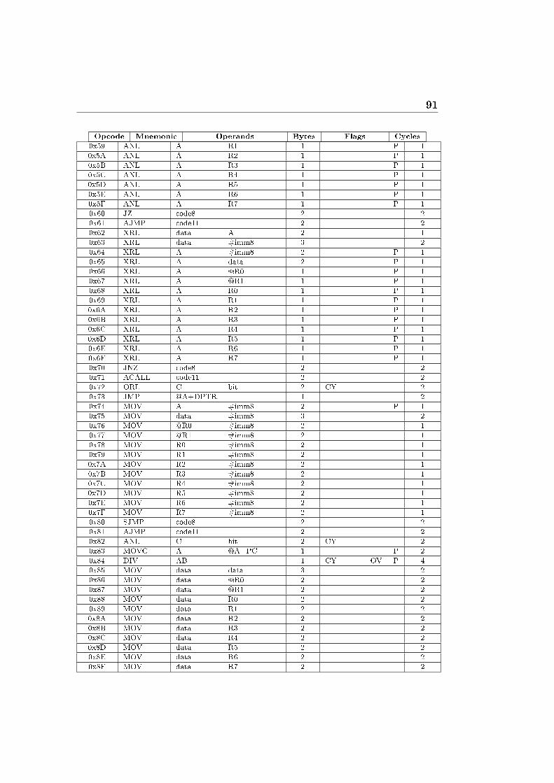
91
Opcode Mnemonic Operands Bytes Flags Cycles
0x59 ANL A R1 1 P 1
0x5A ANL A R2 1 P 1
0x5B ANL A R3 1 P 1
0x5C ANL A R4 1 P 1
0x5D ANL A R5 1 P 1
0x5E ANL A R6 1 P 1
0x5F ANL A R7 1 P 1
0x60 JZ code8 2 2
0x61 AJMP code11 2 2
0x62 XRL data A 2 1
0x63 XRL data #imm8 3 2
0x64 XRL A #imm8 2 P 1
0x65 XRL A data 2 P 1
0x66 XRL A @R0 1 P 1
0x67 XRL A @R1 1 P 1
0x68 XRL A R0 1 P 1
0x69 XRL A R1 1 P 1
0x6A XRL A R2 1 P 1
0x6B XRL A R3 1 P 1
0x6C XRL A R4 1 P 1
0x6D XRL A R5 1 P 1
0x6E XRL A R6 1 P 1
0x6F XRL A R7 1 P 1
0x70 JNZ code8 2 2
0x71 ACALL code11 2 2
0x72 ORL C bit 2 CY 2
0x73 JMP @A+DPTR 1 2
0x74 MOV A #imm8 2 P 1
0x75 MOV data #imm8 3 2
0x76 MOV @R0 #imm8 2 1
0x77 MOV @R1 #imm8 2 1
0x78 MOV R0 #imm8 2 1
0x79 MOV R1 #imm8 2 1
0x7A MOV R2 #imm8 2 1
0x7B MOV R3 #imm8 2 1
0x7C MOV R4 #imm8 2 1
0x7D MOV R5 #imm8 2 1
0x7E MOV R6 #imm8 2 1
0x7F MOV R7 #imm8 2 1
0x80 SJMP code8 2 2
0x81 AJMP code11 2 2
0x82 ANL C bit 2 CY 2
0x83 MOVC A @A+PC 1 P 2
0x84 DIV AB 1 CY OV P 4
0x85 MOV data data 3 2
0x86 MOV data @R0 2 2
0x87 MOV data @R1 2 2
0x88 MOV data R0 2 2
0x89 MOV data R1 2 2
0x8A MOV data R2 2 2
0x8B MOV data R3 2 2
0x8C MOV data R4 2 2
0x8D MOV data R5 2 2
0x8E MOV data R6 2 2
0x8F MOV data R7 2 2
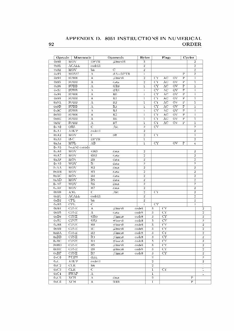
92APPENDIX D. 8051 INSTRUCTIONS IN NUMERICAL
ORDER
Opcode Mnemonic Operands Bytes Flags Cycles
0x90 MOV DPTR #imm16 3 2
0x91 ACALL code11 2 2
0x92 MOV bit C 2 2
0x93 MOVC A @A+DPTR 1 P 2
0x94 SUBB A #imm8 2 CY AC OV P 1
0x95 SUBB A data 2 CY AC OV P 1
0x96 SUBB A @R0 1 CY AC OV P 1
0x97 SUBB A @R1 1 CY AC OV P 1
0x98 SUBB A R0 1 CY AC OV P 1
0x99 SUBB A R1 1 CY AC OV P 1
0x9A SUBB A R2 1 CY AC OV P 1
0x9B SUBB A R3 1 CY AC OV P 1
0x9C SUBB A R4 1 CY AC OV P 1
0x9D SUBB A R5 1 CY AC OV P 1
0x9E SUBB A R6 1 CY AC OV P 1
0x9F SUBB A R7 1 CY AC OV P 1
0xA0 ORL C /bit 2 CY 2
0xA1 AJMP code11 2 2
0xA2 MOV C bit 2 CY 1
0xA3 INC DPTR 1 2
0xA4 MUL AB 1 CY OV P 4
0xA5 Invalid opcode
0xA6 MOV @R0 data 2 2
0xA7 MOV @R1 data 2 2
0xA8 MOV R0 data 2 2
0xA9 MOV R1 data 2 2
0xAA MOV R2 data 2 2
0xAB MOV R3 data 2 2
0xAC MOV R4 data 2 2
0xAD MOV R5 data 2 2
0xAE MOV R6 data 2 2
0xAF MOV R7 data 2 2
0xB0 ANL C /bit 2 CY 2
0xB1 ACALL code11 2 2
0xB2 CPL bit 2 1
0xB3 CPL C 1 CY 1
0xB4 CJNE A #imm8 code8 3 CY 2
0xB5 CJNE A data code8 3 CY 2
0xB6 CJNE @R0 #imm8 code8 3 CY 2
0xB7 CJNE @R1 #imm8 code8 3 CY 2
0xB8 CJNE R0 #imm8 code8 3 CY 2
0xB9 CJNE R1 #imm8 code8 3 CY 2
0xBA CJNE R2 #imm8 code8 3 CY 2
0xBB CJNE R3 #imm8 code8 3 CY 2
0xBC CJNE R4 #imm8 code8 3 CY 2
0xBD CJNE R5 #imm8 code8 3 CY 2
0xBE CJNE R6 #imm8 code8 3 CY 2
0xBF CJNE R7 #imm8 code8 3 CY 2
0xC0 PUSH data 2 2
0xC1 AJMP code11 2 2
0xC2 CLR bit 2 1
0xC3 CLR C 1 CY 1
0xC4 SWAP A 1 1
0xC5 XCH A data 2 P 1
0xC6 XCH A @R0 1 P 1

93
Opcode Mnemonic Operands Bytes Flags Cycles
0xC7 XCH A @R1 1 P 1
0xC8 XCH A R0 1 P 1
0xC9 XCH A R1 1 P 1
0xCA XCH A R2 1 P 1
0xCB XCH A R3 1 P 1
0xCC XCH A R4 1 P 1
0xCD XCH A R5 1 P 1
0xCE XCH A R6 1 P 1
0xCF XCH A R7 1 P 1
0xD0 POP data 2 2
0xD1 ACALL code11 2 2
0xD2 SETB bit 2 1
0xD3 SETB C 1 CY 1
0xD4 DA A 1 CY P 1
0xD5 DJNZ data code8 3 2
0xD6 XCHD A @R0 1 P 1
0xD7 XCHD A @R1 1 P 1
0xD8 DJNZ R0 code8 2 2
0xD9 DJNZ R1 code8 2 2
0xDA DJNZ R2 code8 2 2
0xDB DJNZ R3 code8 2 2
0xDC DJNZ R4 code8 2 2
0xDD DJNZ R5 code8 2 2
0xDE DJNZ R6 code8 2 2
0xDF DJNZ R7 code8 2 2
0xE0 MOVX A @DPTR 1 P 2
0xE1 AJMP code11 2 2
0xE2 MOVX A @R0 1 P 2
0xE3 MOVX A @R1 1 P 2
0xE4 CLR A 1 P 1
0xE5 MOV A data 2 P 1
0xE6 MOV A @R0 1 P 1
0xE7 MOV A @R1 1 P 1
0xE8 MOV A R0 1 P 1
0xE9 MOV A R1 1 P 1
0xEA MOV A R2 1 P 1
0xEB MOV A R3 1 P 1
0xEC MOV A R4 1 P 1
0xED MOV A R5 1 P 1
0xEE MOV A R6 1 P 1
0xEF MOV A R7 1 P 1
0xF0 MOVX @DPTR A 1 2
0xF1 ACALL code11 2 2
0xF2 MOVX @R0 A 1 2
0xF3 MOVX @R1 A 1 2
0xF4 CPL A 1 P 1
0xF5 MOV data A 2 1
0xF6 MOV @R0 A 1 1
0xF7 MOV @R1 A 1 1
0xF8 MOV R0 A 1 1
0xF9 MOV R1 A 1 1
0xFA MOV R2 A 1 1
0xFB MOV R3 A 1 1
0xFC MOV R4 A 1 1
0xFD MOV R5 A 1 1

94APPENDIX D. 8051 INSTRUCTIONS IN NUMERICAL
ORDER
Opcode Mnemonic Operands Bytes Flags Cycles
0xFE MOV R6 A 1 1
0xFF MOV R7 A 1 1
Table D.1: 8051 Instructions in numerical Order
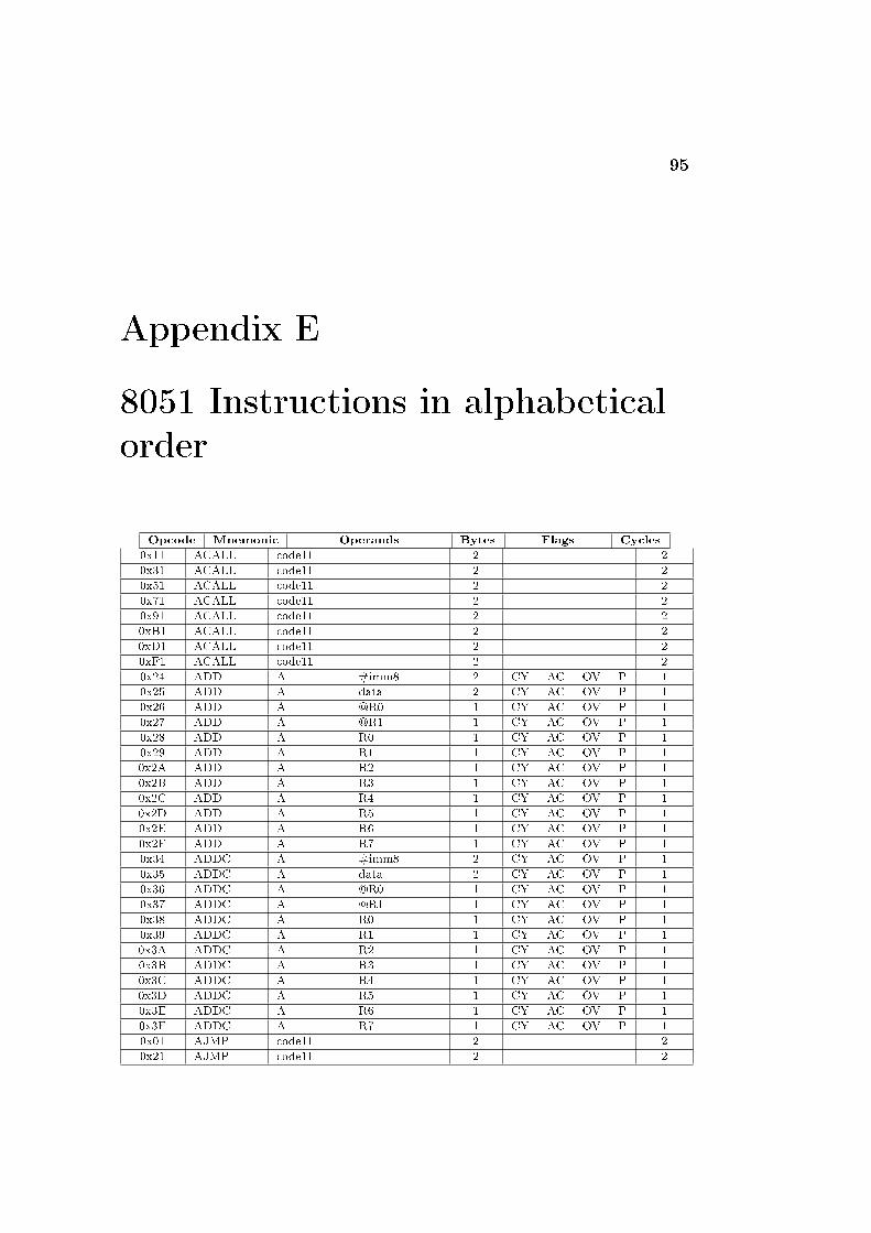
95
Appendix E
8051 Instructions in alphabetical
order
Opcode Mnemonic Operands Bytes Flags Cycles
0x11 ACALL code11 2 2
0x31 ACALL code11 2 2
0x51 ACALL code11 2 2
0x71 ACALL code11 2 2
0x91 ACALL code11 2 2
0xB1 ACALL code11 2 2
0xD1 ACALL code11 2 2
0xF1 ACALL code11 2 2
0x24 ADD A #imm8 2 CY AC OV P 1
0x25 ADD A data 2 CY AC OV P 1
0x26 ADD A @R0 1 CY AC OV P 1
0x27 ADD A @R1 1 CY AC OV P 1
0x28 ADD A R0 1 CY AC OV P 1
0x29 ADD A R1 1 CY AC OV P 1
0x2A ADD A R2 1 CY AC OV P 1
0x2B ADD A R3 1 CY AC OV P 1
0x2C ADD A R4 1 CY AC OV P 1
0x2D ADD A R5 1 CY AC OV P 1
0x2E ADD A R6 1 CY AC OV P 1
0x2F ADD A R7 1 CY AC OV P 1
0x34 ADDC A #imm8 2 CY AC OV P 1
0x35 ADDC A data 2 CY AC OV P 1
0x36 ADDC A @R0 1 CY AC OV P 1
0x37 ADDC A @R1 1 CY AC OV P 1
0x38 ADDC A R0 1 CY AC OV P 1
0x39 ADDC A R1 1 CY AC OV P 1
0x3A ADDC A R2 1 CY AC OV P 1
0x3B ADDC A R3 1 CY AC OV P 1
0x3C ADDC A R4 1 CY AC OV P 1
0x3D ADDC A R5 1 CY AC OV P 1
0x3E ADDC A R6 1 CY AC OV P 1
0x3F ADDC A R7 1 CY AC OV P 1
0x01 AJMP code11 2 2
0x21 AJMP code11 2 2

96APPENDIX E. 8051 INSTRUCTIONS IN ALPHABETICAL
ORDER
Opcode Mnemonic Operands Bytes Flags Cycles
0x41 AJMP code11 2 2
0x61 AJMP code11 2 2
0x81 AJMP code11 2 2
0xA1 AJMP code11 2 2
0xC1 AJMP code11 2 2
0xE1 AJMP code11 2 2
0x52 ANL data A 2 1
0x53 ANL data #imm8 3 2
0x54 ANL A #imm8 2 P 1
0x55 ANL A data 2 P 1
0x56 ANL A @R0 1 P 1
0x57 ANL A @R1 1 P 1
0x58 ANL A R0 1 P 1
0x59 ANL A R1 1 P 1
0x5A ANL A R2 1 P 1
0x5B ANL A R3 1 P 1
0x5C ANL A R4 1 P 1
0x5D ANL A R5 1 P 1
0x5E ANL A R6 1 P 1
0x5F ANL A R7 1 P 1
0x82 ANL C bit 2 CY 2
0xB0 ANL C /bit 2 CY 2
0xB4 CJNE A #imm8 code8 3 CY 2
0xB5 CJNE A data code8 3 CY 2
0xB6 CJNE @R0 #imm8 code8 3 CY 2
0xB7 CJNE @R1 #imm8 code8 3 CY 2
0xB8 CJNE R0 #imm8 code8 3 CY 2
0xB9 CJNE R1 #imm8 code8 3 CY 2
0xBA CJNE R2 #imm8 code8 3 CY 2
0xBB CJNE R3 #imm8 code8 3 CY 2
0xBC CJNE R4 #imm8 code8 3 CY 2
0xBD CJNE R5 #imm8 code8 3 CY 2
0xBE CJNE R6 #imm8 code8 3 CY 2
0xBF CJNE R7 #imm8 code8 3 CY 2
0xC2 CLR bit 2 1
0xC3 CLR C 1 CY 1
0xE4 CLR A 1 P 1
0xB2 CPL bit 2 1
0xB3 CPL C 1 CY 1
0xF4 CPL A 1 P 1
0xD4 DA A 1 CY P 1
0x14 DEC A 1 P 1
0x15 DEC data 2 1
0x16 DEC @R0 1 1
0x17 DEC @R1 1 1
0x18 DEC R0 1 1
0x19 DEC R1 1 1
0x1A DEC R2 1 1
0x1B DEC R3 1 1
0x1C DEC R4 1 1
0x1D DEC R5 1 1
0x1E DEC R6 1 1
0x1F DEC R7 1 1
0x84 DIV AB 1 CY OV P 4
0xD5 DJNZ data code8 3 2

97
Opcode Mnemonic Operands Bytes Flags Cycles
0xD8 DJNZ R0 code8 2 2
0xD9 DJNZ R1 code8 2 2
0xDA DJNZ R2 code8 2 2
0xDB DJNZ R3 code8 2 2
0xDC DJNZ R4 code8 2 2
0xDD DJNZ R5 code8 2 2
0xDE DJNZ R6 code8 2 2
0xDF DJNZ R7 code8 2 2
0x04 INC A 1 P 1
0x05 INC data 2 1
0x06 INC @R0 1 1
0x07 INC @R1 1 1
0x08 INC R0 1 1
0x09 INC R1 1 1
0x0A INC R2 1 1
0x0B INC R3 1 1
0x0C INC R4 1 1
0x0D INC R5 1 1
0x0E INC R6 1 1
0x0F INC R7 1 1
0xA3 INC DPTR 1 2
0x20 JB bit code8 3 2
0x10 JBC bit code8 3 2
0x40 JC code8 2 2
0x73 JMP @A+DPTR 1 2
0x30 JNB bit code8 3 2
0x50 JNC code8 2 2
0x70 JNZ code8 2 2
0x60 JZ code8 2 2
0x12 LCALL code16 3 2
0x02 LJMP code16 3 2
0x74 MOV A #imm8 2 P 1
0x75 MOV data #imm8 3 2
0x76 MOV @R0 #imm8 2 1
0x77 MOV @R1 #imm8 2 1
0x78 MOV R0 #imm8 2 1
0x79 MOV R1 #imm8 2 1
0x7A MOV R2 #imm8 2 1
0x7B MOV R3 #imm8 2 1
0x7C MOV R4 #imm8 2 1
0x7D MOV R5 #imm8 2 1
0x7E MOV R6 #imm8 2 1
0x7F MOV R7 #imm8 2 1
0x85 MOV data data 3 2
0x86 MOV data @R0 2 2
0x87 MOV data @R1 2 2
0x88 MOV data R0 2 2
0x89 MOV data R1 2 2
0x8A MOV data R2 2 2
0x8B MOV data R3 2 2
0x8C MOV data R4 2 2
0x8D MOV data R5 2 2
0x8E MOV data R6 2 2
0x8F MOV data R7 2 2
0x90 MOV DPTR #imm16 3 2

98APPENDIX E. 8051 INSTRUCTIONS IN ALPHABETICAL
ORDER
Opcode Mnemonic Operands Bytes Flags Cycles
0x92 MOV bit C 2 2
0xA2 MOV C bit 2 CY 1
0xA6 MOV @R0 data 2 2
0xA7 MOV @R1 data 2 2
0xA8 MOV R0 data 2 2
0xA9 MOV R1 data 2 2
0xAA MOV R2 data 2 2
0xAB MOV R3 data 2 2
0xAC MOV R4 data 2 2
0xAD MOV R5 data 2 2
0xAE MOV R6 data 2 2
0xAF MOV R7 data 2 2
0xE5 MOV A data 2 P 1
0xE6 MOV A @R0 1 P 1
0xE7 MOV A @R1 1 P 1
0xE8 MOV A R0 1 P 1
0xE9 MOV A R1 1 P 1
0xEA MOV A R2 1 P 1
0xEB MOV A R3 1 P 1
0xEC MOV A R4 1 P 1
0xED MOV A R5 1 P 1
0xEE MOV A R6 1 P 1
0xEF MOV A R7 1 P 1
0xF5 MOV data A 2 1
0xF6 MOV @R0 A 1 1
0xF7 MOV @R1 A 1 1
0xF8 MOV R0 A 1 1
0xF9 MOV R1 A 1 1
0xFA MOV R2 A 1 1
0xFB MOV R3 A 1 1
0xFC MOV R4 A 1 1
0xFD MOV R5 A 1 1
0xFE MOV R6 A 1 1
0xFF MOV R7 A 1 1
0x83 MOVC A @A+PC 1 P 2
0x93 MOVC A @A+DPTR 1 P 2
0xE0 MOVX A @DPTR 1 P 2
0xE2 MOVX A @R0 1 P 2
0xE3 MOVX A @R1 1 P 2
0xF0 MOVX @DPTR A 1 2
0xF2 MOVX @R0 A 1 2
0xF3 MOVX @R1 A 1 2
0xA4 MUL AB 1 CY OV P 4
0x00 NOP 1 1
0x42 ORL data A 2 1
0x43 ORL data #imm8 3 2
0x44 ORL A #imm8 2 P 1
0x45 ORL A data 2 P 1
0x46 ORL A @R0 1 P 1
0x47 ORL A @R1 1 P 1
0x48 ORL A R0 1 P 1
0x49 ORL A R1 1 P 1
0x4A ORL A R2 1 P 1
0x4B ORL A R3 1 P 1
0x4C ORL A R4 1 P 1
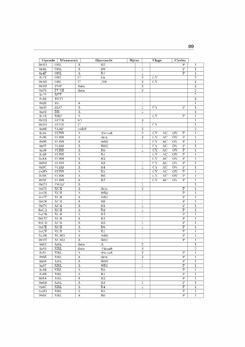
99
Opcode Mnemonic Operands Bytes Flags Cycles
0x4D ORL A R5 1 P 1
0x4E ORL A R6 1 P 1
0x4F ORL A R7 1 P 1
0x72 ORL C bit 2 CY 2
0xA0 ORL C /bit 2 CY 2
0xD0 POP data 2 2
0xC0 PUSH data 2 2
0x22 RET 1 2
0x32 RETI 1 2
0x23 RL A 1 1
0x33 RLC A 1 CY P 1
0x03 RR A 1 1
0x13 RRC A 1 CY P 1
0xD2 SETB bit 2 1
0xD3 SETB C 1 CY 1
0x80 SJMP code8 2 2
0x94 SUBB A #imm8 2 CY AC OV P 1
0x95 SUBB A data 2 CY AC OV P 1
0x96 SUBB A @R0 1 CY AC OV P 1
0x97 SUBB A @R1 1 CY AC OV P 1
0x98 SUBB A R0 1 CY AC OV P 1
0x99 SUBB A R1 1 CY AC OV P 1
0x9A SUBB A R2 1 CY AC OV P 1
0x9B SUBB A R3 1 CY AC OV P 1
0x9C SUBB A R4 1 CY AC OV P 1
0x9D SUBB A R5 1 CY AC OV P 1
0x9E SUBB A R6 1 CY AC OV P 1
0x9F SUBB A R7 1 CY AC OV P 1
0xC4 SWAP A 1 1
0xC5 XCH A data 2 P 1
0xC6 XCH A @R0 1 P 1
0xC7 XCH A @R1 1 P 1
0xC8 XCH A R0 1 P 1
0xC9 XCH A R1 1 P 1
0xCA XCH A R2 1 P 1
0xCB XCH A R3 1 P 1
0xCC XCH A R4 1 P 1
0xCD XCH A R5 1 P 1
0xCE XCH A R6 1 P 1
0xCF XCH A R7 1 P 1
0xD6 XCHD A @R0 1 P 1
0xD7 XCHD A @R1 1 P 1
0x62 XRL data A 2 1
0x63 XRL data #imm8 3 2
0x64 XRL A #imm8 2 P 1
0x65 XRL A data 2 P 1
0x66 XRL A @R0 1 P 1
0x67 XRL A @R1 1 P 1
0x68 XRL A R0 1 P 1
0x69 XRL A R1 1 P 1
0x6A XRL A R2 1 P 1
0x6B XRL A R3 1 P 1
0x6C XRL A R4 1 P 1
0x6D XRL A R5 1 P 1
0x6E XRL A R6 1 P 1
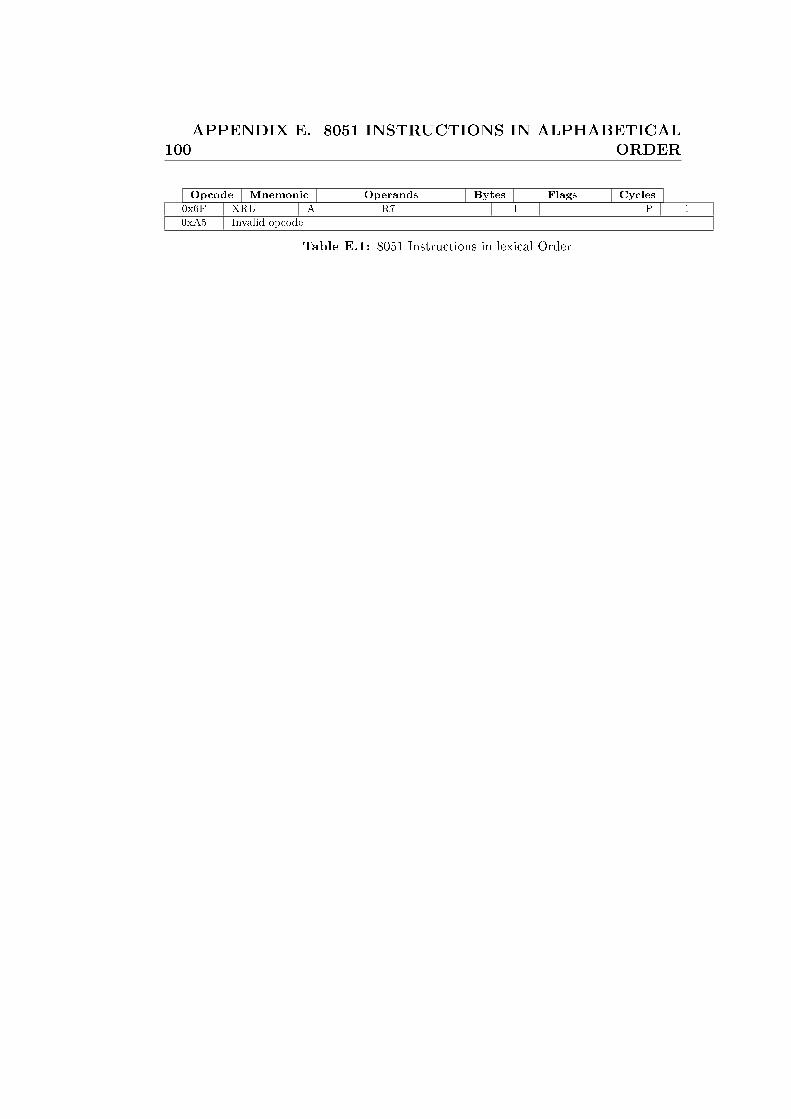
100APPENDIX E. 8051 INSTRUCTIONS IN ALPHABETICAL
ORDER
Opcode Mnemonic Operands Bytes Flags Cycles
0x6F XRL A R7 1 P 1
0xA5 Invalid opcode
Table E.1: 8051 Instructions in lexical Order
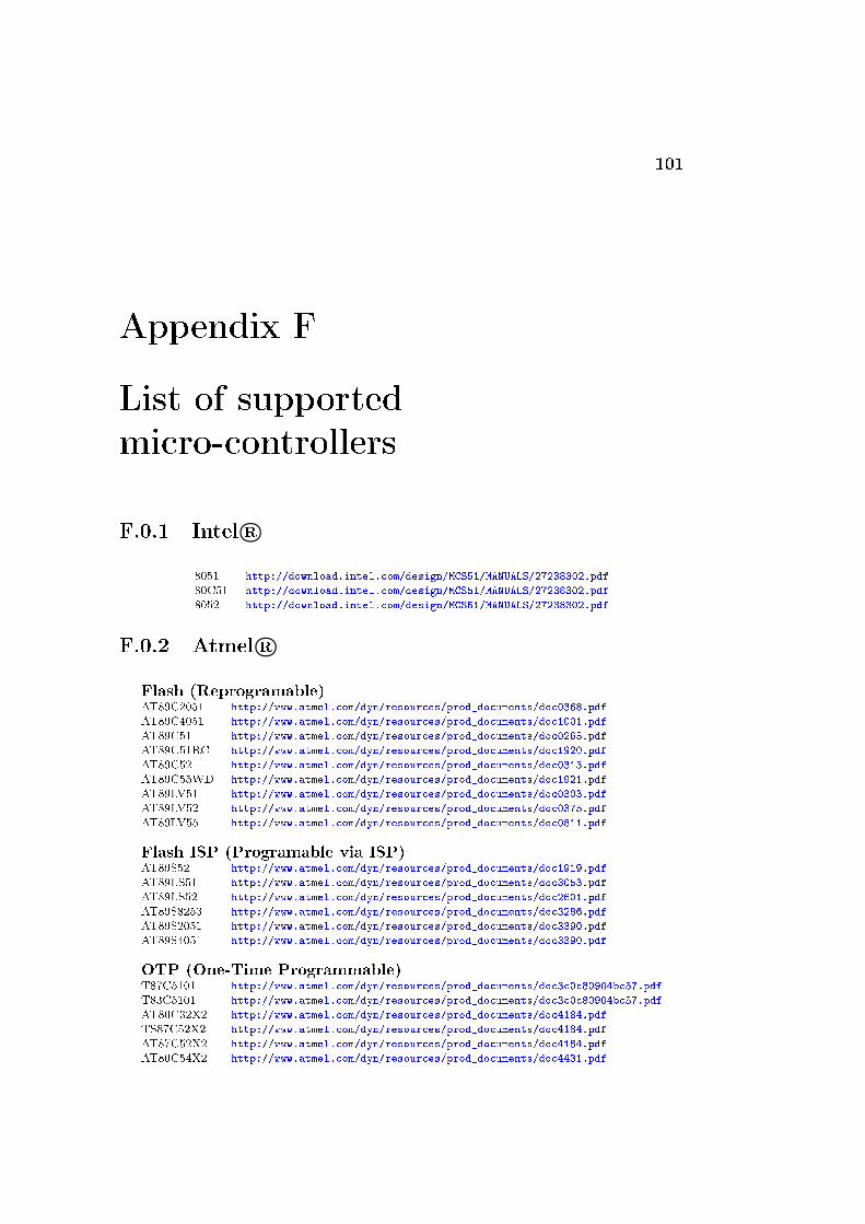
101
Appendix F
List of supported
micro-controllers
F.0.1 Intel R©
8051 http://download.intel.com/design/MCS51/MANUALS/27238302.pdf
80C51 http://download.intel.com/design/MCS51/MANUALS/27238302.pdf
8052 http://download.intel.com/design/MCS51/MANUALS/27238302.pdf
F.0.2 Atmel R©
Flash (Reprogramable)AT89C2051 http://www.atmel.com/dyn/resources/prod_documents/doc0368.pdf
AT89C4051 http://www.atmel.com/dyn/resources/prod_documents/doc1001.pdf
AT89C51 http://www.atmel.com/dyn/resources/prod_documents/doc0265.pdf
AT89C51RC http://www.atmel.com/dyn/resources/prod_documents/doc1920.pdf
AT89C52 http://www.atmel.com/dyn/resources/prod_documents/doc0313.pdf
AT89C55WD http://www.atmel.com/dyn/resources/prod_documents/doc1921.pdf
AT89LV51 http://www.atmel.com/dyn/resources/prod_documents/doc0303.pdf
AT89LV52 http://www.atmel.com/dyn/resources/prod_documents/doc0375.pdf
AT89LV55 http://www.atmel.com/dyn/resources/prod_documents/doc0811.pdf
Flash ISP (Programable via ISP)AT89S52 http://www.atmel.com/dyn/resources/prod_documents/doc1919.pdf
AT89LS51 http://www.atmel.com/dyn/resources/prod_documents/doc3053.pdf
AT89LS52 http://www.atmel.com/dyn/resources/prod_documents/doc2601.pdf
AT89S8253 http://www.atmel.com/dyn/resources/prod_documents/doc3286.pdf
AT89S2051 http://www.atmel.com/dyn/resources/prod_documents/doc3390.pdf
AT89S4051 http://www.atmel.com/dyn/resources/prod_documents/doc3390.pdf
OTP (One-Time Programmable)T87C5101 http://www.atmel.com/dyn/resources/prod_documents/doc3c0c80904bc57.pdf
T83C5101 http://www.atmel.com/dyn/resources/prod_documents/doc3c0c80904bc57.pdf
AT80C32X2 http://www.atmel.com/dyn/resources/prod_documents/doc4184.pdf
TS87C52X2 http://www.atmel.com/dyn/resources/prod_documents/doc4184.pdf
AT87C52X2 http://www.atmel.com/dyn/resources/prod_documents/doc4184.pdf
AT80C54X2 http://www.atmel.com/dyn/resources/prod_documents/doc4431.pdf

102APPENDIX F. LIST OF SUPPORTED
MICRO-CONTROLLERS
ROMT83C5102 http://www.atmel.com/dyn/resources/prod_documents/doc3c0c80904bc57.pdf
TS80C32X2 http://www.atmel.com/dyn/resources/prod_documents/doc4184.pdf
TS80C52X2 http://www.atmel.com/dyn/resources/prod_documents/doc4184.pdf
AT80C58X2 http://www.atmel.com/dyn/resources/prod_documents/doc4431.pdf
AT87C54X2 http://www.atmel.com/dyn/resources/prod_documents/doc4431.pdf
AT87C58X2 http://www.atmel.com/dyn/resources/prod_documents/doc4431.pdf
TS80C54X2 http://www.atmel.com/dyn/resources/prod_documents/doc4431.pdf
TS80C58X2 http://www.atmel.com/dyn/resources/prod_documents/doc4431.pdf
TS87C54X2 http://www.atmel.com/dyn/resources/prod_documents/doc4431.pdf
AT80C52X2 http://www.atmel.com/dyn/resources/prod_documents/doc4184.pdf
TS87C58X2 http://www.atmel.com/dyn/resources/prod_documents/doc4431.pdf
ROMlessTS80C31X2 http://www.atmel.com/dyn/resources/prod_documents/doc4428.pdf
AT80C31X2 http://www.atmel.com/dyn/resources/prod_documents/doc4428.pdf

103
Appendix G
Change log
1.3.11 -> 1.4
* Bug fixes
* Added new Virtual HW component: LCD display controlled by HD44780
* Added new Virtual HW component: simulated DS1620 temperature sensor
* Added new Virtual HW component: File interface
* Added AT89S51
* Improved performance of Virtual HW
* Added support for spelling checker (Hunspell)
* Added 8051 Instruction table
* Improved table of symbols on the right panel
* Final draft of the handbook
1.3.10 -> 1.3.11
* Bug fixes
* New interface for hardware control plug-ins
* Added new assembler directives: ELSEIF ELSEIFN ELSEIFDEF ELSEIFNDEF
* Removed assembler directive: EXITM
1.3.9 -> 1.3.10
* Bug fixes
* Extended help menu
* Extended global configuration dialog
* Added support for multiple widget styles and GUI background colors
* Added draft of handbook
* Added basic support for assembler and simulator regression testing
* Added regular support for i18n (internationalization)
* Modified welcome dialog
* Added support for external links in the GUI
1.3.8 -> 1.3.9
* Bug fixes
1.3.7 -> 1.3.8
* Bug fixes
* Added feature "Global Font Size Factor" (see MCU 8051 IDE configuration dialog)
* Added breakpoint validation
1.3.6 -> 1.3.7
* Bug fixes
1.3.5 -> 1.3.6

104 APPENDIX G. CHANGE LOG
* Bug fixes
1.3.4 -> 1.3.5
* Bug fixes
1.3.3 -> 1.3.4
* "Modernized" GUI
* Bug fixes
1.3.1 -> 1.3.3
* Bug fixes
1.3.1 -> 1.3.2
* Bug fixes
1.3 -> 1.3.1
* Dependency on TclX is now only optional
* Important chage !: Native assembler now expands macro instructions before doing conditional
assembly and before defining constants and variables ! Control sequence $NOMACROSFIRST can
be used to change this behavior to the state of previous versions.
* Added support for AS31 assembler
* Added files notepad
* Improved instruction help panel
* Native assembler was extended to support these directives: "IFN IFDEF IFNDEF BYTE FLAG REPT
TIMES" and these constrol sequences: "$NOXR $NOXREF $XR $XREF $NOSB $SB $RESTORE $RS $SA
$SAVE $PHILIPS $NOPI $PI $NOTABS $NOMOD51 $NOBUILTIN $NOMO $MO $MOD51 $NOMACRO $NOMR $LI
$NOLI $GENONLY $GO $NOGEN $NOGE $GEN $GE $ $EJ $NODB $NODEBUG $DB $DEBUG $CONDONLY $NOCOND
$COND $TT $PW $PL $MR $MACRO $INC $WARNING $ERROR $DA $NOMACROSFIRST"
* Added stack monitor
* Various bug fixes
1.2 -> 1.3
* New dependency: TclX (tested with v8.4)
* Added RS232/UART debugger
* A few changes in assembler
* Bug fixes (Thanks to Miroslav Hradílek for many useful bug reports)
1.1.1 -> 1.2
* Bug fixes
* Added tab bar
1.1 -> 1.1.1
* Added "Special calculator"
* Added "Base converter"
* Many tiny improvements
1.0.9 -> 1.1
* Added support for new MCUs from Intel R©: 8031, 8751, 8032, 8752, 80C31, 87C51, 80C52,
87C52, 80C32, 80C54, 87C54, 80C58, 87C58
* Added support for simulating virtual hardware
* Improved simulator (Implemented UART (experimental support), improved support for timers, etc.)
* Improved register watches
* Improved editor (improved autocompletion and many other things)
* Improved panel "Instruction details"
* Improved 8-segment editor
* Bug fixes in assembler, disassembler and simulator engine
* Some other bug fixes
* Added utility "Scribble notepad"
* Improved graph panel
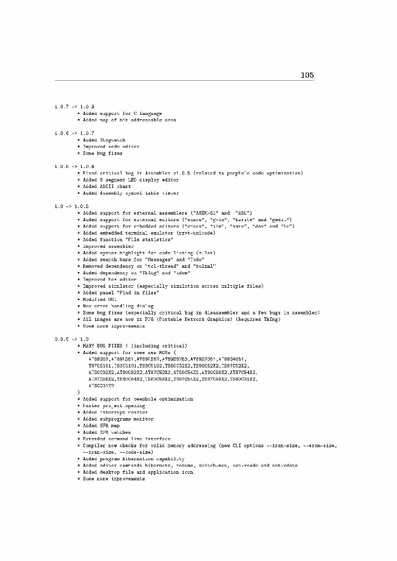
105
1.0.7 -> 1.0.9
* Added support for C language
* Added map of bit addressable area
1.0.6 -> 1.0.7
* Added Stopwatch
* Improved code editor
* Some bug fixes
1.0.5 -> 1.0.6
* Fixed critical bug in Assembler v1.0.5 (related to peephole code optimization)
* Added 8 segment LED display editor
* Added ASCII chart
* Added Assembly symbol table viewer
1.0 -> 1.0.5
* Added support for external assemblers ("ASEM-51" and "ASL")
* Added support for external editors ("emacs", "gvim", "kwrite" and "gedit")
* Added support for embedded editors ("emacs", "vim", "nano", "dav" and "le")
* Added embedded terminal emulator (rxvt-unicode)
* Added function "File statistics"
* Improved assembler
* Added syntax highlight for code listing (*.lst)
* Added search bars for "Messages" and "Todo"
* Removed dependency on "tcl-thread" and "tclxml"
* Added dependency on "TkImg" and "tdom"
* Improved hex editor
* Improved simulator (especially simulation across multiple files)
* Added panel "Find in files"
* Modified GUI
* New error handling dialog
* Some bug fixes (especially critical bug in disassembler and a few bugs in assembler)
* All images are now in PNG (Portable Network Graphics) (Requires TkImg)
* Some more improvements
0.9.5 -> 1.0
* MANY BUG FIXES ! (including critical)
* Added support for some new MCUs (
AT89S52,AT89LS51,AT89LS52,AT89S8253,AT89S2051,AT89S4051,
T87C5101,T83C5101,T83C5102,TS80C32X2,TS80C52X2,TS87C52X2,
AT80C32X2,AT80C52X2,AT87C52X2,AT80C54X2,AT80C58X2,AT87C54X2,
AT87C58X2,TS80C54X2,TS80C58X2,TS87C54X2,TS87C58X2,TS80C31X2,
AT80C31X2
)
* Added support for peephole optimization
* Faster project opening
* Added interrupt monitor
* Added subprograms monitor
* Added SFR map
* Added SFR watches
* Extended command line interface
* Compiler now checks for valid memory addressing (new CLI options --iram-size, --eram-size,
--xram-size, --code-size)
* Added program hibernation capability
* Added editor commands hibernate, resume, switch-mcu, set-xcode and set-xdata
* Added desktop file and application icon
* Some more improvements
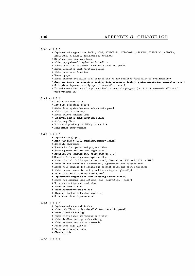
106 APPENDIX G. CHANGE LOG
0.9.1 -> 0.9.5
* Implemented support for 80C51, 8052, AT89C2051, AT89C4051, AT89C51, AT89C51RC, AT89C52,
AT89C55WD, AT89LV51, AT89LV52 and AT89LV55
* Simulator can now step back
* Added popup-based completion for editor
* Added tool tips for bits in simulator control panel
* Added simulator configuration dialog
* Added auto save function
* Manual page
* Added support for multi-view (editor can be now splitted vertically or horizontally)
* Many bug fixes (in compiler, editor, file selection dialog, syntax highlight, simulator, etc.)
* Some minor improvements (graph, disassembler, etc.)
* Thread extension is no longer required to run this program (but custom commands will won't
work without it)
0.9.0 -> 0.9.1
* New hexadecimal editor
* New file selection dialog
* Added file system browser tab on left panel
* Added tips on start-up
* Added editor command line
* Improved editor configuration dialog
* A few bug fixes
* Removed dependency on IWidgets and Tix
* Some minor improvements
0.8.7 -> 0.9.0
* Implemented graph
* Many bug fixes (GUI, compiler, memory leaks)
* Editable shortcuts
* Bookmarks for opened and project files
* Search panels in left and right panel
* Modified GUI (checkboxes, radio buttons ...)
* Support for various encodings and EOLs
* Added "Tools" -> "Change letter case", "Normalize HEX" and "SIM -> BIN"
* Added editor functions "Lowercase", "Uppercase" and "Capitalize"
* Added help windows for opened and project files and opened projects
* Added pop-up menus for entry and text widgets (globally)
* Fixed problem with fonts (bad sizes)
* Implemented support for line wrapping (experimental)
* Added new command line options (see `mcu8051ide --help')
* More status tips and tool tips
* Added welcome dialog
* Added demonstration project
* Cleaner, faster and safer compiler
* Some more minor improvements
0.8.5 -> 0.8.7
* Implemented code validation
* Added tab "Instruction details" (on the right panel)
* Added Clean Up dialog
* Added Right Panel configuration dialog
* Added Toolbar configuration dialog
* Added support for custom commands
* Fixed some bugs (in GUI)
* Fixed many memory leaks
* Cleaner code
0.8.4 -> 0.8.5

107
* Fixed many bugs in GUI
* Improved editor
* Extended calculator
* Redesigned editor configuration dialog
* Added functions "Tools -> Reformat code" and "Tools -> Sim2Hex"
* Extended CLI (--reset-user-settings, --config-file, --compile, --hex2bin ...)
0.8.1 -> 0.8.4
* Fixed many bugs ... (including critical)
* Added compiler configuration dialog
* Added calculator timers preset
* Added dialog about
* Added support for exporting highlighted source code to LaTeX source
* Added many ToolTips
* Added StatusBar tips
* Added splash screen
* Added support for command line options
* All images are now *.XPM (X PixMap) (require Tix package)
* Changed installation procedure
0.8.0 -> 0.8.1
* Fixed some bugs in compiler (not critical)
* Fixed bug in to do list (saving text as SGML)
* Fixed bug in project management
* Added pop-up menu to to do list

108 APPENDIX G. CHANGE LOG

109
List of Tables
1 Software requirements . . . . . . . . . . . . . . . . . . . . . . . . . 6
3.1 Available commands . . . . . . . . . . . . . . . . . . . . . . . . . . 193.2 Data register watches: Register address . . . . . . . . . . . . . . . 263.3 Symbol colors and icons in default settings . . . . . . . . . . . . . . 273.4 List of pseudo-variables . . . . . . . . . . . . . . . . . . . . . . . . 34
4.1 Radix speci�ers . . . . . . . . . . . . . . . . . . . . . . . . . . . . . 414.2 Expression operators . . . . . . . . . . . . . . . . . . . . . . . . . . 414.3 Code addresses . . . . . . . . . . . . . . . . . . . . . . . . . . . . . 494.4 Plain numbers, these symbols are always de�ned! . . . . . . . . . . 494.5 Prede�ned SFR bit addresses . . . . . . . . . . . . . . . . . . . . . 494.6 Prede�ned SFR addresses . . . . . . . . . . . . . . . . . . . . . . . 504.7 Segment types . . . . . . . . . . . . . . . . . . . . . . . . . . . . . . 514.8 Directives directly related to macros . . . . . . . . . . . . . . . . . 544.9 Special instruction operands . . . . . . . . . . . . . . . . . . . . . . 584.10 Instruction mnemonics . . . . . . . . . . . . . . . . . . . . . . . . . 584.11 Directives . . . . . . . . . . . . . . . . . . . . . . . . . . . . . . . . 584.12 Expression operators . . . . . . . . . . . . . . . . . . . . . . . . . . 584.13 Assembler controls . . . . . . . . . . . . . . . . . . . . . . . . . . . 584.14 Control sequences a�ecting code listing . . . . . . . . . . . . . . . . 61
D.1 8051 Instructions in numerical Order . . . . . . . . . . . . . . . . . 92
E.1 8051 Instructions in lexical Order . . . . . . . . . . . . . . . . . . . 98

110 LIST OF TABLES

111
List of Figures
1.1 i8051 micro-architecture . . . . . . . . . . . . . . . . . . . . . . . . 12
2.1 MCU 8051 IDE with the demonstration project opened within it . 15
2.2 Project creation dialog . . . . . . . . . . . . . . . . . . . . . . . . . 16
3.1 Syntax validation con�guration button . . . . . . . . . . . . . . . . 17
3.2 Spell checker con�guration button . . . . . . . . . . . . . . . . . . 18
3.3 Syntax highlight, syntax validation and the pop-up based auto-completion all in action . . . . . . . . . . . . . . . . . . . . . . . . 18
3.4 Main panel of the simulator . . . . . . . . . . . . . . . . . . . . . . 20
3.5 Highlighted SFR register . . . . . . . . . . . . . . . . . . . . . . . . 20
3.6 Tool tip help for a special function bit . . . . . . . . . . . . . . . . 20
3.7 Representation of a register value in various numeric bases . . . . . 20
3.8 GPIO Graph . . . . . . . . . . . . . . . . . . . . . . . . . . . . . . 21
3.9 Messages panel . . . . . . . . . . . . . . . . . . . . . . . . . . . . . 21
3.10 Personal notes . . . . . . . . . . . . . . . . . . . . . . . . . . . . . . 22
3.11 Calculator . . . . . . . . . . . . . . . . . . . . . . . . . . . . . . . . 22
3.12 Embedded rxvt-unicode terminal emulator, with the Midnight Com-mander running in it . . . . . . . . . . . . . . . . . . . . . . . . . . 23
3.13 SFR watches . . . . . . . . . . . . . . . . . . . . . . . . . . . . . . 24
3.14 Instruction details . . . . . . . . . . . . . . . . . . . . . . . . . . . 25
3.15 Data register watches . . . . . . . . . . . . . . . . . . . . . . . . . . 25
3.16 Subprograms call monitor . . . . . . . . . . . . . . . . . . . . . . . 26
3.17 Map of the bit addressable area . . . . . . . . . . . . . . . . . . . . 27
3.18 Stack monitor . . . . . . . . . . . . . . . . . . . . . . . . . . . . . . 27
3.19 Symbol viewer . . . . . . . . . . . . . . . . . . . . . . . . . . . . . 28
3.20 ASCII chart . . . . . . . . . . . . . . . . . . . . . . . . . . . . . . . 28
3.21 8051 Instruction Table . . . . . . . . . . . . . . . . . . . . . . . . . 28
3.22 8-segment editor . . . . . . . . . . . . . . . . . . . . . . . . . . . . 29
3.23 Base convertor . . . . . . . . . . . . . . . . . . . . . . . . . . . . . 30
3.24 UART/RS-232 debugger . . . . . . . . . . . . . . . . . . . . . . . . 30
3.25 MCU code memory editor . . . . . . . . . . . . . . . . . . . . . . . 31
3.26 Interrupt monitor . . . . . . . . . . . . . . . . . . . . . . . . . . . . 32

112 LIST OF FIGURES
3.27 Change letter case dialog . . . . . . . . . . . . . . . . . . . . . . . . 343.28 Custom commands con�guration dialog . . . . . . . . . . . . . . . 353.29 Editor con�guration dialog . . . . . . . . . . . . . . . . . . . . . . . 353.30 Main toolbar . . . . . . . . . . . . . . . . . . . . . . . . . . . . . . 373.31 Global con�guration dialog . . . . . . . . . . . . . . . . . . . . . . 37
6.1 DS1620 simulator and its log window . . . . . . . . . . . . . . . . . 676.2 PALE I/O interface . . . . . . . . . . . . . . . . . . . . . . . . . . . 676.3 LED Panel . . . . . . . . . . . . . . . . . . . . . . . . . . . . . . . 686.4 LED Display . . . . . . . . . . . . . . . . . . . . . . . . . . . . . . 686.5 M LED Display . . . . . . . . . . . . . . . . . . . . . . . . . . . . . 686.6 LED Matrix . . . . . . . . . . . . . . . . . . . . . . . . . . . . . . . 696.7 Matrix Keypad . . . . . . . . . . . . . . . . . . . . . . . . . . . . . 696.8 Simple Keypad . . . . . . . . . . . . . . . . . . . . . . . . . . . . . 706.9 Simulated LCD display . . . . . . . . . . . . . . . . . . . . . . . . . 706.10 HD44780 Log . . . . . . . . . . . . . . . . . . . . . . . . . . . . . . 706.11 CGRAM . . . . . . . . . . . . . . . . . . . . . . . . . . . . . . . . . 706.12 DDRAM . . . . . . . . . . . . . . . . . . . . . . . . . . . . . . . . . 706.13 View on CGROM . . . . . . . . . . . . . . . . . . . . . . . . . . . . 70
7.1 An example of HW control plug-in . . . . . . . . . . . . . . . . . . 717.2 A basic example of a plug-in . . . . . . . . . . . . . . . . . . . . . . 74
B.1 Assembler regression test run in terminal emulator . . . . . . . . . 83
C.1 O�cial web page of the MCU 8051 IDE project . . . . . . . . . . . 85
Related Documents