Sky Exams: PART-66 courseware Category A B1 Level 1 2 3 12–Helicopter aerodynamics, structures and systems 02–Flight control systems Module 1 2-0 2 Helicopter Aerodynamics, Structures and Systems Flight Control Systems 12- 02- 1

Welcome message from author
This document is posted to help you gain knowledge. Please leave a comment to let me know what you think about it! Share it to your friends and learn new things together.
Transcript
Sky Exams: PART-66 courseware Category A B1 Level 1 2 3
12–Helicopter aerodynamics, structures and systems 02–Flight control systems
Mo d u l e 1 2-02 H e l i co p t e r A e ro d yn am i c s , S t ru c t u re s a n d Sys te m s
Flight Control Systems
12- 02- 1

Sky Exams: PART-66 courseware Category A B1 Level 1 2 3
12–Helicopter aerodynamics, structures and systems 02–Flight control systems
Table of contents
I. INTRODUCTION .......................................................................................................................................................................................................................................... 6 1. AXIS: ........................................................................................................................................................................................................................................................... 6 1.1. Plane of rotation .................................................................................................................................................................................................................................... 7 1.2. Axis of rotation ...................................................................................................................................................................................................................................... 7 1.3. Flight control components ................................................................................................................................................................................................................... 8
2. PROPERTIES: ......................................................................................................................................................................................................................................... 11 3. MAIN PILOT COMMANDS: .................................................................................................................................................................................................................. 11 4. OTHER PILOT COMMANDS: ............................................................................................................................................................................................................... 12
II. CYCLIC CONTROL ................................................................................................................................................................................................................................... 14 1. GENERAL: ............................................................................................................................................................................................................................................... 14
1.1. Tip path plane- TPP ......................................................................................................................................................................................................................... 15 1.2. Swashplates principle ...................................................................................................................................................................................................................... 16
2. FUNCTIONS OF CYCLIC CONTROL: ................................................................................................................................................................................................ 17 2.1. Main functions of cyclic control: ..................................................................................................................................................................................................... 17 2.2. Additional functions: ......................................................................................................................................................................................................................... 22
III. COLLECTIVE CONTROL ........................................................................................................................................................................................................................ 23 1. COLLECTIVE CONTROL AND PITCH ANGLE: ............................................................................................................................................................................... 24 2. THROTTLECONTROL: ......................................................................................................................................................................................................................... 24 3. GOVERNOR AND CORRELATORS: .................................................................................................................................................................................................. 25
IV. SWASHPLATE ........................................................................................................................................................................................................................................... 29 1. SWASHPLATEASSEMBLY: ................................................................................................................................................................................................................ 29
1.1. Swashplate components ................................................................................................................................................................................................................. 31 1.2. Swashplate description ................................................................................................................................................................................................................... 31
2. SWASHPLATEOPERATION: ............................................................................................................................................................................................................... 35 2.1. Collective input operation: ............................................................................................................................................................................................................... 35 2.2. Cyclic operation: ............................................................................................................................................................................................................................... 36
3. SPIDER CONTROL MECHANISM ...................................................................................................................................................................................................... 37 V. YAW CONTROL ........................................................................................................................................................................................................................................ 38
1. ANTI-TORQUECONTROL: ................................................................................................................................................................................................................... 38 2. TAILROTOR: ........................................................................................................................................................................................................................................... 39
2.1. Heading control: ............................................................................................................................................................................................................................... 39 2.2. Tail rotor commands: ....................................................................................................................................................................................................................... 41
12- 02- 2

Sky Exams: PART-66 courseware Category A B1 Level 1 2 3
12–Helicopter aerodynamics, structures and systems 02–Flight control systems
2.3. Fenestron tail rotor systems: ............................................................................................................................................................................................................ 43 2.4. Tail rotor control systems: ................................................................................................................................................................................................................. 45
3. TWINNON-COAXIAL ROTORS: .......................................................................................................................................................................................................... 46 3.1. Tandem rotors: .................................................................................................................................................................................................................................... 46 3.2. Side-by-side rotors ............................................................................................................................................................................................................................. 47 3.3. Twin inter-meshing rotors .................................................................................................................................................................................................................. 48 3.4. Twin coaxial rotors ............................................................................................................................................................................................................................. 50
4. BLEED AIR–NOTAR HELICOPTERS: ............................................................................................................................................................................................... 53
4.1. NOTAR® concept: .............................................................................................................................................................................................................................. 53 4.2. NOTAR® system operation: ............................................................................................................................................................................................................. 54
VI. MAIN ROTOR HEAD–DESIGN AND OPERATION FEATURES ...................................................................................................................................................... 57 1. INTRODUCTION: .................................................................................................................................................................................................................................... 57 2. COMPARISONOFMAINROTORTYPES ............................................................................................................................................................................................. 57 2.1. Rigid rotor systems: ........................................................................................................................................................................................................................... 58 2.2. Semi rigid rotor systems .................................................................................................................................................................................................................... 63 2.3. Fully articulated rotor system ............................................................................................................................................................................................................ 66 2.4. Combination rotor system ................................................................................................................................................................................................................. 73 2.5. Bearing less Main Rotors (BMR technology) ................................................................................................................................................................................. 75
VII. BLADE DAMPERS: FUNCTION AND CONSTRUCTION ............................................................................................................................................................... 78 1. ROTORVIBRATIONS: ........................................................................................................................................................................................................................... 78
1.1. Low frequency vibrations ................................................................................................................................................................................................................... 78 1.2. Medium and high frequency vibrations: .......................................................................................................................................................................................... 78
2. HELICOPTER GROUND AND AIR RESONANCE: .......................................................................................................................................................................... 78 2.1. Ground resonance phenomenon: .................................................................................................................................................................................................... 80 2.2. Air resonance phenomenon: ............................................................................................................................................................................................................. 80 2.3. Ground (and air) resonance solutions: ............................................................................................................................................................................................ 80
2. DAMPERFUNCTION: ............................................................................................................................................................................................................................. 81 2.1. Hydraulic dampers: ............................................................................................................................................................................................................................ 81 2.2. Elastomeric dampers: ........................................................................................................................................................................................................................ 82 2.3. Variable dampers: .............................................................................................................................................................................................................................. 85 2.4. Fluid filled dampers : .......................................................................................................................................................................................................................... 86
3. DAMPER CONSTRUCTION: ................................................................................................................................................................................................................ 87
3.1. Hydraulic dampers: ............................................................................................................................................................................................................................ 87 3.2. Elastomeric inertial dampers: ........................................................................................................................................................................................................... 88 3.3. Embedded inertial dampers .............................................................................................................................................................................................................. 89
VIII. ROTORBLADES: MAIN AND TAILROTOR BLADE CONSTRUCTION AND ATTACHMENT ................................................................................................ 91 1. GENERAL: ............................................................................................................................................................................................................................................... 91
12- 02- 3

Sky Exams: PART-66 courseware Category A B1 Level 1 2 3
12–Helicopter aerodynamics, structures and systems 02–Flight control systems
2. BLADE DESIGNS: .................................................................................................................................................................................................................................. 91 3. BLADE STRUCTURES AND MATERIALS:....................................................................................................................................................................................... 94
3.1. Forces acting on blades .................................................................................................................................................................................................................... 94 3.2. Types of blades................................................................................................................................................................................................................................... 95 3.3. Wood blades ....................................................................................................................................................................................................................................... 96 3.4. Metal blades ........................................................................................................................................................................................................................................ 96 3.5. Composite blades ............................................................................................................................................................................................................................... 98 3.6. NACA design airfoils .......................................................................................................................................................................................................................... 99 3.7. ONERA design airfoils ..................................................................................................................................................................................................................... 100
4. ROTOR TRANSMISSION: .................................................................................................................................................................................................................. 104
5.1. Main purposes .................................................................................................................................................................................................................................. 104 5.2. Clutch ................................................................................................................................................................................................................................................. 105 5.3. Belt driveclutch .................................................................................................................................................................................................................................. 107 5.4. Centrifugal clutch .............................................................................................................................................................................................................................. 107
5. MAIN ROTOR HEADS: ........................................................................................................................................................................................................................ 108
5.1. Hooke joint teetering head .............................................................................................................................................................................................................. 108 5.2. Bell 206 teetering head .................................................................................................................................................................................................................... 109 5.3. Tri-hinge head ................................................................................................................................................................................................................................... 109 5.4. Door-hinge hub ................................................................................................................................................................................................................................. 110 5.5. Semi-teetering head with elastomeric element ............................................................................................................................................................................ 111
6. MAIN ROTOR CONSTRUCTION AND ATTACHMENT ................................................................................................................................................................. 111
6.1. Rotorhead of the BO-105 ................................................................................................................................................................................................................ 112 6.2. Rotorhead of Lockheed AH-56Cheyenne ..................................................................................................................................................................................... 114 6.3. Rotorhead of Westland Lynx .......................................................................................................................................................................................................... 115 6.4. Rotorhead of Bell-412 ...................................................................................................................................................................................................................... 116 6.5. Rotorhead of EC-725 ....................................................................................................................................................................................................................... 119 6.6. Sikorsky S-64 Skycran eexample: ................................................................................................................................................................................................. 122
6. TAIL ROTOR CONSTRUCTION AND ATTACHEMENT: .............................................................................................................................................................. 135
6.1. Antitorque systems ........................................................................................................................................................................................................................... 136 6.2. Antitorque fenestron systems ......................................................................................................................................................................................................... 137 6.3. Robinson R22 antitorque example................................................................................................................................................................................................. 138
IX. TRIM CONTROL, FIXED AND ADJUSTABLE STABILIZERS ....................................................................................................................................................... 139 1. TRIMCONTROL: ................................................................................................................................................................................................................................... 139
1.1. Introduction ........................................................................................................................................................................................................................................ 139 1.2. Magnetic brakes ............................................................................................................................................................................................................................... 141 1.3. Electrical trim actuators ................................................................................................................................................................................................................... 142
2. FIXED AND ADJUSTABLESTABILIZERS: ..................................................................................................................................................................................... 145
12- 02- 4

Sky Exams: PART-66 courseware Category A B1 Level 1 2 3
12–Helicopter aerodynamics, structures and systems 02–Flight control systems
2.1. Fixed stabilizers ................................................................................................................................................................................................................................ 145 2.2. Adjustable stabilizers ....................................................................................................................................................................................................................... 147
X. SYSTEM OPERATION: MANUAL, HYDRAULIC, ELECTRICAL AND FLY-BY-WIRE .............................................................................................................. 150 1. MANUALSYSTEMOPERATION: ....................................................................................................................................................................................................... 150
1.1. Introduction ........................................................................................................................................................................................................................................ 150 1.2. Screw jacks (or jackscrews) ........................................................................................................................................................................................................... 150 1.3. Cables, pulleys, chains and pushrods ........................................................................................................................................................................................... 152
2. HYDRAULICSYSTEM OPERATION: ................................................................................................................................................................................................ 152 2.1. Hydro-mechanical: ........................................................................................................................................................................................................................... 152
3. ELECTRO-MECANICALSYSTEM OPERATION (FLY-BY-WIRE): .............................................................................................................................................. 158 XI. ARTIFICIALFEEL .................................................................................................................................................................................................................................. 163
1. ARTIFICIAL FEEL SYSTEMS: ........................................................................................................................................................................................................... 163 1.1. A simple spring feel units : .............................................................................................................................................................................................................. 163 1.2. Q feel units: ....................................................................................................................................................................................................................................... 164
2. MAIN ROTOR CONTROLSYSTEM FEEL–GRADIENT UNITS: ................................................................................................................................................... 167 3. TAIL ROTOR CONTROL SYSTEM FEEL– YAW PEDAL DAMPERS: ....................................................................................................................................... 170 4. FEEL INTEGRATION WITH A UT OF LIGHT SYSTEMS: ............................................................................................................................................................ 173
XII. BALANCING AND RIGGING .............................................................................................................................................................................................................. 175 1. MAIN ROTOR BLADE ALIGNMENT: ............................................................................................................................................................................................... 175 2. UNBALANCED SEMI RIGID ROTOR SYSTEMS: .......................................................................................................................................................................... 175
2.1. Lateral: ............................................................................................................................................................................................................................................... 175 2.2. Chordwise: ......................................................................................................................................................................................................................................... 176 2.2. Spanwise: .......................................................................................................................................................................................................................................... 176 2.3. Combined .......................................................................................................................................................................................................................................... 177
3. VERTICAL VIBRATIONS: ................................................................................................................................................................................................................... 177
3.1. Extreme low frequency vibrations: ................................................................................................................................................................................................. 178 3.2. Low frequency vibrations ................................................................................................................................................................................................................. 178 3.3. Medium frequency vibrations: ......................................................................................................................................................................................................... 178 3.4. High frequency vibrations: .............................................................................................................................................................................................................. 179
4. MAIN ROTOR BLADE TRACKING: .................................................................................................................................................................................................. 179 4.1. Electronic blade tracker: .................................................................................................................................................................................................................. 179 4.2. Reflector tracking:............................................................................................................................................................................................................................. 180 4.3. Strobe light: ....................................................................................................................................................................................................................................... 180
12- 02- 5

Sky Exams: PART-66 courseware Category A B1 Level 1 2 3
12–Helicopter aerodynamics, structures and systems 02–Flight control systems
I. INTRODUCTION
1. AXIS:
The flight control systems allow the operation on the three axis device:
Roll control (longitudinal axis),
Pitch control(lateral axis),and
Yaw control or direction (vertical axis).
12- 02- 6

Sky Exams: PART-66 courseware Category A B1 Level 1 2 3
12–Helicopter aerodynamics, structures and systems 02–Flight control systems
1.1. Plane of rotation:
A plane formed by the average tip path of the blades is known as the plane of rotation. The plane of rotation is at a right angle to the axis of rotation.
1.2. Axis of rotation:
An imaginary line that passes through a point on which a body rotates is called the axis of rotation. Its rotation is at a right angle to the plane of rotation.
Disc area (A):
The span length of one blade is used as the radius. The area of the hub in the disc area is not included since it doesn't make any lift (but is negligible).
The disc area is the total space in the area of the circle formed by the rotating rotor blades.
The following formula is used to figure disc area:
12- 02- 7

Sky Exams: PART-66 courseware Category A B1 Level 1 2 3
12–Helicopter aerodynamics, structures and systems 02–Flight control systems
where:
A:discarea,
π=3.1416,
R:radius.
A =πR2
1.3. Flight control components:
Flight control on helicopters is obtained by changing the configuration of the main and tail rotors. The lift force is generated by the blades of the main rotor that are usually in a number between two and six.
To manoeuvre a helicopter three controls are used; a collective pitch lever, cyclic pitch stick and yaw pedals.
12- 02- 8
Sky Exams: PART-66 courseware Category A B1 Level 1 2 3
12–Helicopter aerodynamics, structures and systems 02–Flight control systems
Collective pitch lever:
Movement of the collective pitch lever will increase or decrease the pitch angle of all main rotor blades, by the same amount and at the same time. Increasing the pitch on all main rotor blades will increase the total rotor thrust, and decreasing it will have the opposite effect.
Cyclic pitch lever:
The cyclic pitch stick is used to tilt the main rotor disc, forwards, backwards and to the left or the right, or some combination of these.
This will provide a thrust in the direction in which the disc is tilted, and will cause the helicopter to move in that direction.
The tilting of the main rotor disc is achieved by independently adjusting the pitch on individual rotor blades causing them to move upwards or downwards. When cyclic pitch inputs are made the main rotor blades will be subject to an increase or decrease in their pitch angle as they rotate, and so the disc remains tilted in the direction selected by the pilot.
Governor/FADEC controls:
It is normal for modern helicopter engines to remain at a fixed flight idle speed, which is controlled by a fuel governor or computer controlled FADEC (Full Authority Digital Engine Control system), although some older helicopters, and some of those below the 5700Kg MTOM weight category, provide a hand throttle twist grip on the collective pitch lever.
In governed or FADEC systems an increase or decrease in the power required is automatically achieved, in systems using a hand throttle it is necessary for the pilot to make adjustments to the engine RPM in response to control inputs, obviously the governed or FADEC systems are more accurate and relieve the pilot of the additional workload imposed by the need to maintain engine, and therefore rotor RPM.
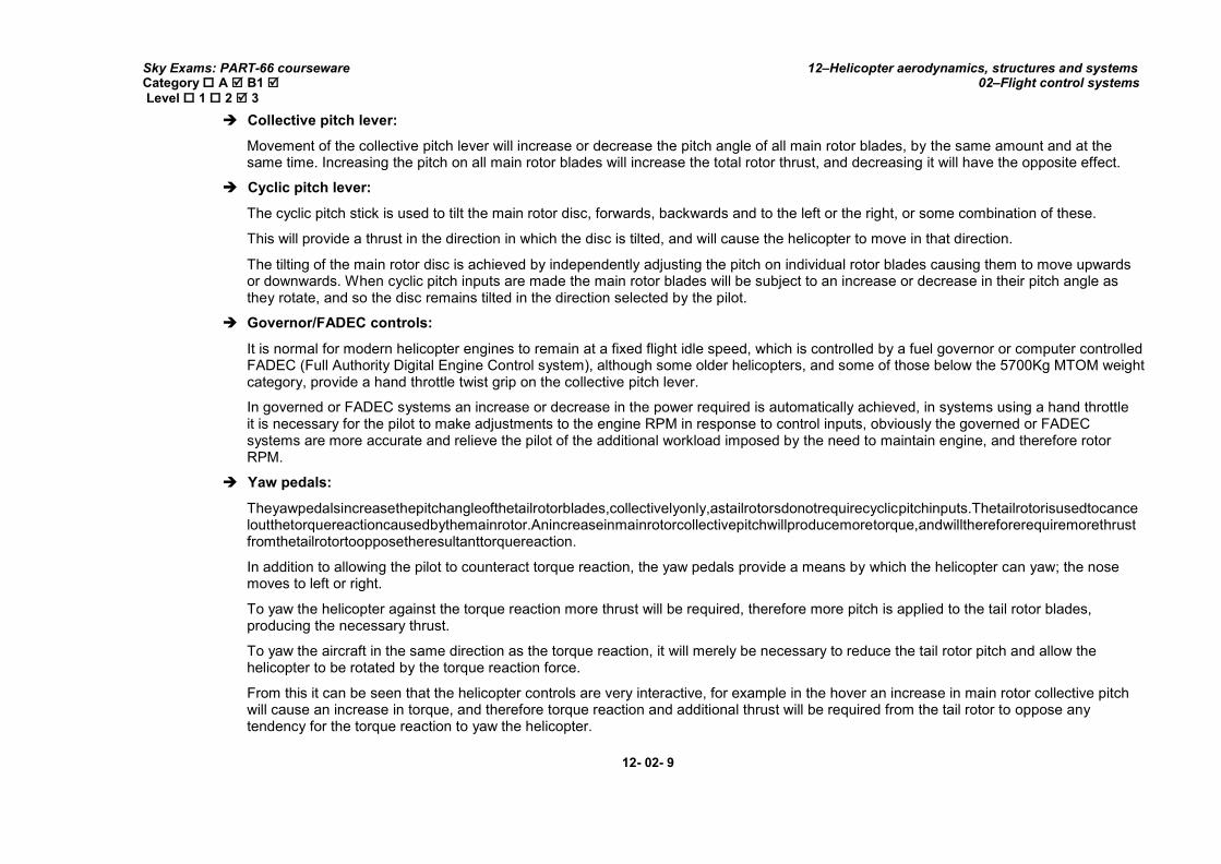
Yaw pedals:
Theyawpedalsincreasethepitchangleofthetailrotorblades,collectivelyonly,astailrotorsdonotrequirecyclicpitchinputs.Thetailrotorisusedtocanceloutthetorquereactioncausedbythemainrotor.Anincreaseinmainrotorcollectivepitchwillproducemoretorque,andwillthereforerequiremorethrustfromthetailrotortoopposetheresultanttorquereaction.
In addition to allowing the pilot to counteract torque reaction, the yaw pedals provide a means by which the helicopter can yaw; the nose moves to left or right.
To yaw the helicopter against the torque reaction more thrust will be required, therefore more pitch is applied to the tail rotor blades, producing the necessary thrust.
To yaw the aircraft in the same direction as the torque reaction, it will merely be necessary to reduce the tail rotor pitch and allow the helicopter to be rotated by the torque reaction force.
From this it can be seen that the helicopter controls are very interactive, for example in the hover an increase in main rotor collective pitch will cause an increase in torque, and therefore torque reaction and additional thrust will be required from the tail rotor to oppose any tendency for the torque reaction to yaw the helicopter.
12- 02- 9

Sky Exams: PART-66 courseware Category A B1 Level 1 2 3
12–Helicopter aerodynamics, structures and systems 02–Flight control systems
Electronic systems:
Many helicopters, other than the most basic types, will incorporate electronic systems within the basic control systems to provide automatic stabilising and, in larger type’s automatic pilot.
Autostab:
Automatic stabilizing systems, sometimes referred to as “auto stab”, are used to ensure that the helicopter remains at a fixed height, heading and speed, regardless of any disturbing influences, such as wind gusts. These systems ensure that the helicopter remains stable, without the need for continuous inputs from the pilot, hence reducing pilot workload and fatigue.
Autopilot:
Many of the larger helicopters have a full autopilot system, where a pre-selected flight plan can be flown with a minimum of inputs from the pilot, thereby further reducing cockpit workload.
12- 02- 10

Sky Exams: PART-66 courseware Category A B1 Level 1 2 3
12–Helicopter aerodynamics, structures and systems 02–Flight control systems
2. PROPERTIES:
Flying control systems are regulated by the FARs, PARTs, and must comply with the following standards:
Sense:
The aircraft must move in the direction signified by the control input, e.g. control column back, and pitch nose-up.
Rigidity:
The control system must be strong enough to withstand any operating loads without excessive distortion, e.g. air loads on the control surfaces (irreversibility).
Stability:
The control surfaces must remain where selected by the pilot and must not be affected by signals which are not self initiated, e.g. vibration and aerodynamic loads.
Safety:
Passengers, cargo and loose particles must safeguard the control system against jamming, chafing, and interference. Guards must therefore be fitted where appropriate to provide the necessary protection.
Fail-Safe:
The control system must be duplicated or be capable of manual operation in the event of hydraulic power failure.
3. MAIN PILOT COMMANDS:
Cyclic-pitch lever—A helicopter pilot controls the pitch, or angle, of the rotor blades with two inputs: the cyclic-and collective-pitch levers, often just shortened to the cyclic and the collective. The cyclic, or "stick," comes out of the floor of the cockpit and sits between the pilot's legs, to enable the pilot tilt the craft to either side or forward and backward.
Collective-pitch lever — The collective-pitch lever is responsible for up-and-down movements. For example, during takeoff, the pilot uses
the collective-pitch lever to increase the pitch of all the rotor blades by the same amount.
Foot pedals — A pair of foot pedals controls the tail rotor. Working the pedals affects which way the helicopter points, so pushing the right pedal deflects the tail of the helicopter to the left and the nose to the right; the left pedal turns the nose to the left.
12- 02- 11

Sky Exams: PART-66 courseware Category A B1 Level 1 2 3
12–Helicopter aerodynamics, structures and systems 02–Flight control systems
4. OTHER PILOT COMMANDS:
Tail boom—The tail boom extends out from the rear of the fuselage and holds the tail rotor assemblies. In some models, the tail boom is
nothing more than an aluminum frame. In others, it's a hollow carbon-fiber or aluminum tube.
Anti-torque tail rotor— Without a tail rotor, the main rotor of a helicopter simply spins the fuselage in the opposite direction. Thankfully,
Igor Sikorsky had the idea to install a tail rotor to counter
12- 02- 12

Sky Exams: PART-66 courseware Category A B1 Level 1 2 3
12–Helicopter aerodynamics, structures and systems 02–Flight control systems
This torque reaction and provide directional control. In twin-rotor helicopters, the torque produced by the rotation of the front rotor is offset by the torque produced by a counter rotating rear rotor.
Landing skids—Some helicopters have wheels, but most have skids, which are hollow tubes with no wheels or brakes. A few models have
skids with two ground-handling wheels.
12- 02- 13

Sky Exams: PART-66 courseware Category A B1 Level 1 2 3
12–Helicopter aerodynamics, structures and systems 02–Flight control systems
II. CYCLIC CONTROL
1. GENERAL:
The cyclic pitch control tilts the main rotor disc by changing the pitch angle of the rotor blades in their cycle of rotation. When the main rotor disc is tilted, the horizontal component of lift moves the helicopter in the direction of tilt.
The rotor disc tilts in the direction that pressure is applied to the cyclic pitch control. If the cyclic is moved forward, the rotor disc tilts forward; if the cyclic is moved aft, the disc tilts aft, and so on.
Cyclic pitch control location
12- 02- 14

Sky Exams: PART-66 courseware Category A B1 Level 1 2 3
12–Helicopter aerodynamics, structures and systems 02–Flight control systems
The cyclic pitch stick is positioned centrally in front of the pilot and co-pilots seats, and is used to tilt the disc, causing the helicopter to move horizontally in any direction.
The cyclic can pivot in all directions.
The cyclic pitch stick is used to tilt the main rotor disc, forwards, backwards and to the left or the right, or some combination of these. This will provide a thrust in the direction in which the disc is tilted, and will cause the helicopter to move in that direction.
The tilting of the main rotor disc is achieved by independently adjusting the pitch on individual rotor blades causing them to move upwards or downwards. When cyclic pitch inputs are made the main rotor blades will be subject to an increase or decrease in their pitch angle as they rotate, and so the disc remains tilted in the direction selected by the pilot.
1.1. Tip path plane -TPP:
The tip path plane, or TPP, is the plane connecting the rotor blade tips as they rotate.
While hovering, the thrust vector of a helicopter is oriented upwards, perpendicular to the tip path plane. In order for the helicopter to travel forward, this thrust vector needs to be rotated slightly in the forward direction.
12- 02- 15

Sky Exams: PART-66 courseware Category A B1 Level 1 2 3
12–Helicopter aerodynamics, structures and systems 02–Flight control systems
1.2. Swashplates principle:
Like all other flight controls it operation is purely instinctive, moving the cyclic pitch stick forwards will tilt the disc forwards, and the helicopter will move forwards, moving the cyclic stick rearwards has the opposite effect.
Cyclic control and swashplate
12- 02- 16

Sky Exams: PART-66 courseware Category A B1 Level 1 2 3
12–Helicopter aerodynamics, structures and systems 02–Flight control systems
Since tilting the rotor hub or rotorshaft is impractical, an alternative means of rotating the “tip path plane” -TPP- is needed. Most modern helicopters use a system of swashplates.Seen in the following diagram, the swashplate system is composed of upper and lower swashplates.
The brown portion of the diagram, including the lower swashplate, remains stationary relative to the helicopter. The upper swashplate (in grey) rotates with the rotor, while remaining parallel to the lower swashplate.
By utilizing what is called cyclic control, the swashplates can be angled so as to vary the pitch of the blades depending on their azimuth angle. As the swashplates are tilted in the proper direction, there is an increased lift on the aft portion of the rotor, causing the blades to flap up, which in turn causes the TPP to rotate forwards. As the TPP rotates forwards, the thrust does as well, imparting a forward acceleration to the helicopter.
2. FUNCTIONS OF CYCLIC CONTROL:
2.1. Main functions of cyclic control:
The rotor disc tilts in the direction that pressure is applied to the cyclic pitch control. If the cyclic is moved forward, the rotor disc tilts forward; if the cyclic is moved aft, the disc tilts aft, and so on.
Because the rotor disc acts like a gyro, the mechanical linkages for the cyclic control rods are rigged in such away that they decrease the pitch angle of the rotor blade approximately 90° before it reaches the direction of cyclic displacement, and increase the pitch angle of the rotor blade approximately 90° after it passes the direction of displacement:
An increase in pitch angle increases angle of attack;
A decrease in pitch angle decreases angle of attack.
For example, if the cyclic is moved forward, the angle of attack decreases as the rotor blade passes the right side of the helicopter and increases on the left side.
This results in maximum downward deflection of the rotor blade in front of the helicopter and maximum upward deflection behind it, causing the rotor disc to tilt forward.
Movement of the cyclic stick to left or right will cause the helicopter to move in that direction.
The cyclic pitch stick is pivoted at its lower end and is connected to two push/pull tubes, one transmitting left/right (roll) movements and the other fore and aft (pitch) movements.
A yoke assembly allows these movements to be made independently so that only roll or pitch inputs may be made without causing movement of the other, however, simultaneous roll and pitch movements can be made if required.
In fore and aft movement, one push/pull tube transmits movements to the control mixing unit.
12- 02- 17

Sky Exams: PART-66 courseware Category A B1 Level 1 2 3
12–Helicopter aerodynamics, structures and systems 02–Flight control systems
Side to side movements operate two push/pull rods which operate in opposite directions, when the cyclic stick is moved to the left one rod will move forwards and the other rearwards, when the stick is moved to the right the opposite will occur.
This is required because there are two lateral (roll) main rotor actuators which must operate in opposition to achieve lateral control, whereas, fore and aft pitch movements are achieved by only one main rotor actuator, that uses the fixed or non-rotating scissors as a datum point about which movements are made.
Cyclic inputs on stationary and rotating swashplate
12- 02- 18

Sky Exams: PART-66 courseware Category A B1 Level 1 2 3
12–Helicopter aerodynamics, structures and systems 02–Flight control systems
Cyclic transmission principle
12- 02- 19
Sky Exams: PART-66 courseware Category A B1 Level 1 2 3
12–Helicopter aerodynamics, structures and systems 02–Flight control systems
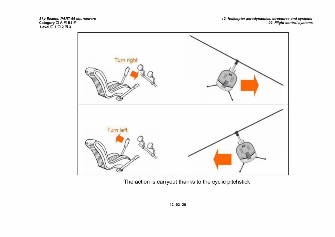
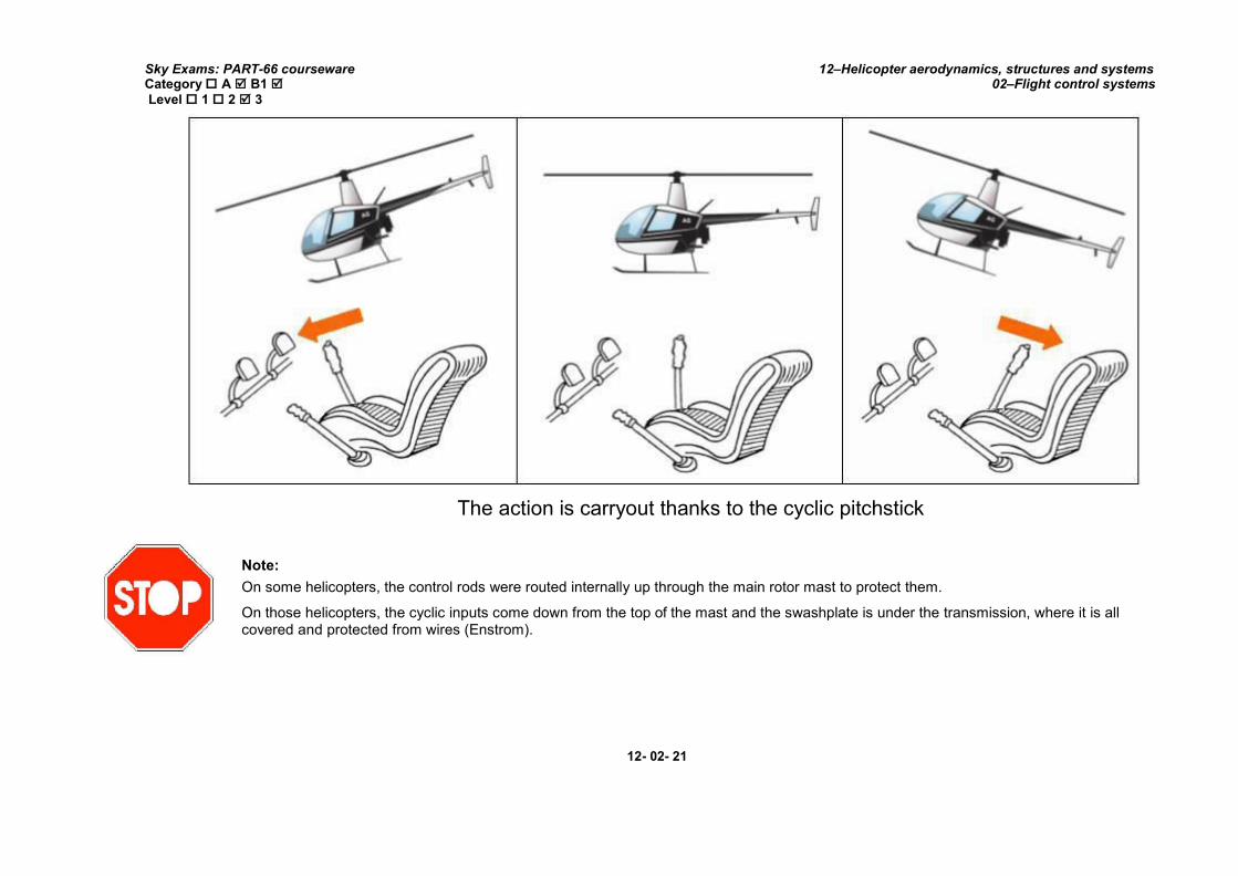
The action is carryout thanks to the cyclic pitchstick
12- 02- 20
Sky Exams: PART-66 courseware Category A B1 Level 1 2 3
12–Helicopter aerodynamics, structures and systems 02–Flight control systems
The action is carryout thanks to the cyclic pitchstick
Note:
On some helicopters, the control rods were routed internally up through the main rotor mast to protect them.
On those helicopters, the cyclic inputs come down from the top of the mast and the swashplate is under the transmission, where it is all covered and protected from wires (Enstrom).
12- 02- 21

Sky Exams: PART-66 courseware Category A B1 Level 1 2 3
12–Helicopter aerodynamics, structures and systems 02–Flight control systems
2.2. Additional functions:
The cyclic stick grip will incorporate switches for operation of important systems; these are normally associated with control trimming, auto-flight or auto-stabilisation, cargo release and communication systems.
12- 02- 22

Sky Exams: PART-66 courseware Category A B1 Level 1 2 3
12–Helicopter aerodynamics, structures and systems 02–Flight control systems
III. COLLECTIVE CONTROL
The collective pitch control (or simply “collective” or “thrust lever”), located on the left side of the pilot’s seat, changes the pitch angle of all main rotor blades simultaneously, or collectively, as the name implies.
Raising the collective pitch control increases the pitch angle the same amount on all blades
12- 02- 23

Sky Exams: PART-66 courseware Category A B1 Level 1 2 3
12–Helicopter aerodynamics, structures and systems 02–Flight control systems
1. COLLECTIVE CONTROL AND PITCH ANGLE:
The collective pitch lever or stick is located by the left side of the pilot's seat and is operated with the left hand. This lever moves up and down pivoting about the aft end and, through a series of mechanical linkages, changes the pitch angle of the main rotor blades.
The collective is used to make changes to the pitch angle of the main rotor blades and does this simultaneously, or collectively, as the name implies.
As the collective pitch control is raised, there is a simultaneous and equal increase in pitch angle of all main rotor blades; as it is lowered, there is a simultaneous and equal decrease in pitch angle.
This is done through a series of mechanical linkages and the amount of movement in the collective lever determines the amount of blade pitch change. An adjustable friction control helps prevent inadvertent collective pitch movement.
Changing the pitch angle on the blades changes the angle of attack on each blade. With a change in angle of attack comes a change in drag, which affects the RPM of the main rotor. As the pitch angle increases, angle of attack increases, drag increases and rotor RPM decreases.
Decreasing pitch angle decreases both angle of attack and drag, while rotor RPM increases.
In order to maintain a constant rotor RPM, which is essential in helicopter operations, a proportionate change in power is required to compensate for the change in drag. This is accomplished with the throttle control or a governor, which automatically adjusts engine power.
2. THROTTLE CONTROL:
The function of the throttle is to regulate engine RPM. If the governor system does not maintain the desired RPM when the collective is raised or lowered, or if those systems are not installed, the throttle must be moved manually with the twist grip in order to maintain RPM.
The throttle control is much like a motor cycle throttle, and works in virtually the same way. Twisting the throttle to the left increases RPM; twisting the throttle to the right decreases RPM.
Note:
A twist grip throttle is usually mounted on the end of the collective lever. The throttles on some turbine helicopters are mounted on the overhead panel or on the floor in the cockpit.
12- 02- 24

Sky Exams: PART-66 courseware Category A B1 Level 1 2 3
12–Helicopter aerodynamics, structures and systems 02–Flight control systems
Twist grip throttle
3. GOVERNOR AND CORRELATORS:
A governor is a sensing device that senses rotor and engine RPM and makes the necessary adjustments in order to keep rotor RPM constant. In normal operations, once the rotor RPM is set, the governor keeps the RPM constant, and there is no need to make any throttle adjustments. Governors are common on all turbine helicopters (as it is a function of the fuel control system of the turbine engine), and used on some piston powered helicopters.
A correlator is a mechanical connection between the collective lever and the engine throttle. When the collective lever is raised, power is automatically increased; when lowered, power is decreased. This system maintains RPM close to the desired value, but still requires adjustment of the throttle for fine tuning.
Some helicopters do not have governors and require coordination of all collective and throttle movements.
When the collective is raised, the throttle must be increased; when the collective is lowered, the throttle must be decreased.
12- 02- 25

Sky Exams: PART-66 courseware Category A B1 Level 1 2 3
12–Helicopter aerodynamics, structures and systems 02–Flight control systems
As with any aircraft control, large adjustments of either collective pitch or throttle should be avoided. All corrections should be made through the use of smooth pressure.
In piston helicopters, the collective pitch is the primary control for manifold pressure, and the throttle is the primary control for RPM. However, the collective pitch control also influences RPM, and the throttle also influences manifold pressure; therefore, each is considered to be a secondary control of the other’s function.
Both the tachometer (RPM indicator) and the manifold pressure gauge must be analyzed to determine which control to use.
If the RPM is and the manifold
pressure is
Solution
Increasing the throttle increases manifold pressure and RPM.
Lowering the collective pitch decreases manifold pressure and increases RPM.
Raising the collective pitch increases manifold pressure and decreases RPM.
Reducing the throttle decreases manifold pressure and RPM.
Relationship between RPM, manifold pressure, collective, and throttle
12- 02- 26

Sky Exams: PART-66 courseware Category A B1 Level 1 2 3
12–Helicopter aerodynamics, structures and systems 02–Flight control systems
Collective transmission principle
12- 02- 27

Sky Exams: PART-66 courseware Category A B1 Level 1 2 3
12–Helicopter aerodynamics, structures and systems 02–Flight control systems
Collective inputs on a stationary and rotating swashplate
12- 02- 28

Sky Exams: PART-66 courseware Category A B1 Level 1 2 3
12–Helicopter aerodynamics, structures and systems 02–Flight control systems
IV. SWASHPLATE
A major part of a helicopter flight control system is the mechanism used to transfer control inputs from the non-rotating parts of the system, to those that are rotating.
There are 2 commonly used methods used to achieve this:
Swashplate,
Spider control.
Of these, the swashplate is perhaps the most common device used for main rotors, and the spider for tail rotors, although there are some helicopters that use spider control for main rotors too.
1. SWASHPLATE ASSEMBLY:
The purpose of the swashplate is to transmit control inputs from the collective and cyclic controls to the main rotor blades. It consists of two main parts: the stationary swashplate and the rotating swashplate.
The swashplate consists of two primary elements through which the rotor mast passes. The swashplate includes a rotating and non-rotating plate, normally referred to as ‘stars’ because of their shape, they may be made from steel, titanium or light alloy, with the choice of material being dependent upon the in-service loads that the swashplate will have to withstand.
The non-rotating star is mounted on to the main rotor gearbox shaft by a large spherical ball, housed in its centre, sometimes referred to as a ‘uniball’. This ball is free to run up and down a slider sleeve, fitted around the shaft.
This non-rotating disc, often referred to as the "stationary star," is attached by a bearing surface to a second disc, often referred to as the "rotating star," which turns with the rotor and is mechanically linked to the rotor blade pitch horns.
The rotating star is fitted to the non-rotating star on a bearing, and so can freely rotate about it.
The rotating and non-rotating swashplates move as a single entity in the horizontal plane, and any change in the horizontal angle of the non-rotating swashplate, will be transferred to the rotating swashplate, which will move to the same angle.
The rotor blade pitch horns are placed approximately 90° ahead of or behind the blade on which they control the pitch change.
12- 02- 29
Sky Exams: PART-66 courseware Category A B1 Level 1 2 3
12–Helicopter aerodynamics, structures and systems 02–Flight control systems
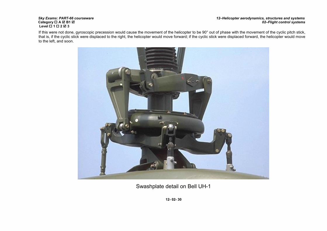
If this were not done, gyroscopic precession would cause the movement of the helicopter to be 90° out of phase with the movement of the cyclic pitch stick, that is, if the cyclic stick were displaced to the right, the helicopter would move forward; if the cyclic stick were displaced forward, the helicopter would move to the left, and soon.
Swashplate detail on Bell UH-1
12- 02- 30

Sky Exams: PART-66 courseware Category A B1 Level 1 2 3
12–Helicopter aerodynamics, structures and systems 02–Flight control systems
1.1. Swashplate components:
Swashplate components
In this figure, collective and cyclic control inputs are transmitted to the stationary swashplate by control rods causing it to tilt or to slide vertically. The pitch links attached from the rotating swashplate to the pitch horns on the rotor hub transmit these movements to the blades.
1.2. Swashplate description:
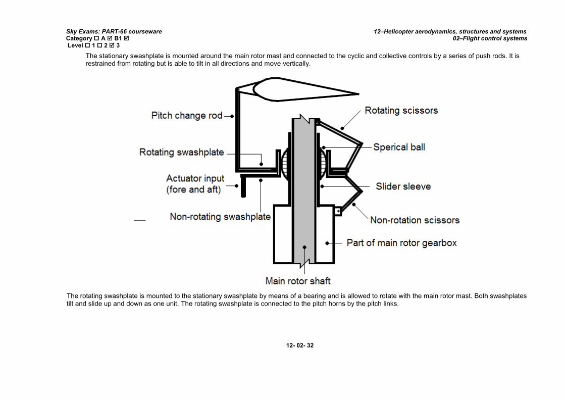
The stationary swashplate is mounted around the main rotor mast and connected to the cyclic and collective controls by a series of push rods. It is restrained from rotating but is able to tilt in all directions and move vertically.
The rotating swashplate is mounted to the stationary swashplate by means of a bearing and is allowed to rotate with the main rotor mast. Both swashplates tilt and slide up and down as one unit. The rotating swashplate is connected to the pitch horns by the pitch links.
The purpose of the swashplate is to transmit control inputs from the collective and cyclic controls to the main rotor blades. It consists of two main parts: the stationary swashplate and the rotating swashplate.
12- 02- 31
Sky Exams: PART-66 courseware Category A B1 Level 1 2 3
12–Helicopter aerodynamics, structures and systems 02–Flight control systems
The stationary swashplate is mounted around the main rotor mast and connected to the cyclic and collective controls by a series of push rods. It is restrained from rotating but is able to tilt in all directions and move vertically.
The rotating swashplate is mounted to the stationary swashplate by means of a bearing and is allowed to rotate with the main rotor mast. Both swashplates tilt and slide up and down as one unit. The rotating swashplate is connected to the pitch horns by the pitch links.
12- 02- 32
Sky Exams: PART-66 courseware Category A B1 Level 1 2 3
12–Helicopter aerodynamics, structures and systems 02–Flight control systems
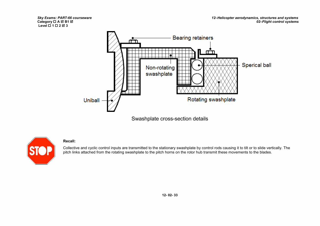
Swashplate cross-section details
Recall:
Collective and cyclic control inputs are transmitted to the stationary swashplate by control rods causing it to tilt or to slide vertically. The pitch links attached from the rotating swashplate to the pitch horns on the rotor hub transmit these movements to the blades.
12- 02- 33

Sky Exams: PART-66 courseware Category A B1 Level 1 2 3
12–Helicopter aerodynamics, structures and systems 02–Flight control systems
12- 02- 34

Sky Exams: PART-66 courseware Category A B1 Level 1 2 3
12–Helicopter aerodynamics, structures and systems 02–Flight control systems
2. SWASHPLATE OPERATION:
Regardless of actual arrangement and manufacturers preference all swashplates transfer control inputs to the main rotor in the same manner, description of the operating sequence is most clearly achieved by use of simple illustrations.
2.1. Collective input operation:
When a collective input is made all 3 actuators will extend or retract by the same amount. The movement of the actuators will raise or lower the swashplate assembly, causing the spherical bearing at its centre to move up or down on the slider shaft. The rotor blades will get a simultaneous and equal collective pitch change, as illustrated, increasing or decreasing total rotor thrust.
The illustration shows this effect when the collective pitch lever is raised, and there is an equal and simultaneous pitch increase on all rotor blades.
12- 02- 35

Sky Exams: PART-66 courseware Category A B1 Level 1 2 3
12–Helicopter aerodynamics, structures and systems 02–Flight control systems
2.2. Cyclic operation:
When the cyclic pitch stick is moved a differential input will be made at the mixing unit and this will be transmitted to the actuators, causing the actuators to rise or lower.
The non-rotating star will tilt, and this action is passed on to the main rotor blades, changing their pitch independently causing the rotor disc to tilt because of phase lag the tilt of the swashplate and rotor disc will not be in the same direction.
As the rotating star rotates, there will be a continuous change in blade pitch depending upon the cyclic pitch stick position.
12- 02- 36

Sky Exams: PART-66 courseware Category A B1 Level 1 2 3
12–Helicopter aerodynamics, structures and systems 02–Flight control systems
The illustration shows the effect when there is a change in fore and aft (pitching) movement, in which case the non-rotating scissors acts as a datum point, and the fore and aft actuator moves the swashplate about it. In the case of a lateral (rolling) input one lateral actuator will rise and the other will fall.
3. SPIDER CONTROL MECHANISM:
Although this type of control layout varies considerably from the swashplate system it performs exactly the same functions and the controls in the cockpit are the same.
There is a separate control run for each of the primary movements of the pilot’s; a cyclic control for lateral movement and cyclic control for fore and aft movement and a collective control. In a typical system each of these is connected separately to a control beam thus eliminating the need for a mixer unit to give collective control, but it does require a special type of control linkage to achieve cyclic movement.
Blade pitch changes are affected by a vertical spindle in a sliding sleeve connected to the blades by spider arms, the spindle and sleeve moving inside the hollow rotor shaft from the gearbox. As the vertical spindle is connected to the blades that are rotating, it follows that the vertical spindle is rotating within the rotor driveshaft; therefore to achieve a link-up of the rotating side of the system and the non-rotating side there is a rotating/non-rotating link with universal movement to give both collective and cyclic movement. (See chapter VIII–Rotor blades).
12- 02- 37

Sky Exams: PART-66 courseware Category A B1 Level 1 2 3
12–Helicopter aerodynamics, structures and systems 02–Flight control systems
V. YAW CONTROL
Helicopters fly and move horizontally using one or more sets of spinning rotor blades. Each of these blades is an airfoil shape which, when moving through the air, force air downwards and in doing so are themselves forced upwards.
There are a number of ways that this torque force is counteracted in rotor design:
Tail rotor; Twin non-coaxial rotors; Contra-rotating coaxial rotors; Bleed air NOTAR (NO Tail Rotor).
1. ANTI-TORQUE CONTROL:
The anti-torque pedals, located on the cabin floor by the pilot’s feet, control the pitch, and therefore the thrust, of the tail rotor blades. The main purpose of the tail rotor is to counteract the torque effect of the main rotor.
Anti-torque pedals
Rewind about 350 years to Newton and his third law of motion: for every action there is an equal and opposite reaction. A helicopter creates lift by spinning its main rotor blade(s) in one direction; this action has an equal and opposite effect on the helicopter fuselage, making it 'want' to spin in the opposite
12- 02- 38

Sky Exams: PART-66 courseware Category A B1 Level 1 2 3
12–Helicopter aerodynamics, structures and systems 02–Flight control systems
direction. Since the torque on the aircraft varies with changes in engine power used by the main rotor, the tail rotor thrust must also be varied. The pedals are connected to the pitch change mechanism on the tail rotor gearbox and allow the pitch angle on the tail rotor blades to be increased or decreased.
Besides counteracting torque of the main rotor, the tail rotor is also used to control the heading of the helicopter while hovering or when making hovering turns. Hovering turns are commonly referred to as “pedal turns”.
This Newton’ law applies to the helicopter fuselage and its rotation in the opposite direction of the main rotor blades unless counteracted and controlled.
To make flight possible and to compensate for this torque, most helicopter designs incorporate an anti-torque rotor or tail rotor. The anti-torque pedals allow the pilot to control the pitch angle of the tail rotor blades, which in forward flight puts the helicopter in longitudinal trim and, while at a hover, enables the pilot to turn the helicopter 360°. The anti-torque pedals are connected to the pitch change mechanism on the tail rotor gearbox and allow the pitch angle on the tail rotor blades to be increased or decreased.
Since the torque on the aircraft varies with changes in engine power used by the main rotor, the tail rotor thrust must also be varied. The pedals are connected to the pitch change mechanism on the tail rotor gearbox and allow the pitch angle on the tail rotor blades to be increased or decreased.
2. TAILROTOR:
The most common configuration is the combination of one main rotor and one tail rotor. The tail rotor will compensate the torque which is produced by the main rotor. The tail rotor is also responsible for the control of the helicopter along the vertical axis, during hover flight.
2.1. Heading control:
The thrust of the tail rotor depends on the pitch angle of the tail rotor blades. This pitch angle can be positive, negative, or zero. A positive pitch angle tends to move the tail to the right. A negative pitch angle moves the tail to the left, while no thrust is produced with a zero pitch angle.
With the right pedal moved forward of the neutral position, the tail rotor either has a negative pitch angle or a small positive pitch angle. The farther forward the right pedal is displaced, the larger the negative pitch angle. The closer the right pedal is to the neutral position, the more positive the pitch angle, and some where in between, it has a zero pitch angle.
As the left pedal is moved forward of the neutral position, the positive pitch angle of the tail rotor increases until it becomes maximum with full forward displacement of the left pedal. If the tail rotor has a negative pitch angle, tail rotor thrust is working in the same direction as the torque of the main rotor.
With a small positive pitch angle, the tail rotor does not produce sufficient thrust to overcome the torque effect of the main rotor during cruise flight. Therefore, if the right pedal is displaced forward of neutral during cruising flight, the tail rotor thrust does not overcome the torque effect, and the nose yaws to the right. With the anti-torque pedals in the neutral position, the tail rotor has a medium positive pitch angle. In medium positive pitch, the tail rotor thrust approximately equals the torque of the main rotor during cruise flight, so the helicopter maintains a constant heading in level flight. The tail rotor is used to control the heading of the helicopter while hovering or when making hovering turns, as well as counteracting the torque of the main rotor.
12- 02- 39

Sky Exams: PART-66 courseware Category A B1 Level 1 2 3
12–Helicopter aerodynamics, structures and systems 02–Flight control systems
If the left pedal is in a forward position, the tail rotor has a high positive pitch position. In this position, tail rotor thrust exceeds the thrust needed to overcome torque effect during cruising flight so the helicopter yaws to the left.
The above explanation is based on cruise power and airspeed. Since the amount of torque is dependent on the amount of engine power being supplied to the main rotor, the relative positions of the pedals required to counteract torque depend upon the amount of power being used at anytime.
The maximum positive pitch angle of the tail rotor is generally some what greater than the maximum negative pitch angle available. This is because the primary purpose of the tail rotor is to counteract the torque of the main rotor.
12- 02- 40

Sky Exams: PART-66 courseware Category A B1 Level 1 2 3
12–Helicopter aerodynamics, structures and systems 02–Flight control systems
The capability for tail rotors to produce thrust to the left (negative pitch angle is necessary, because during autorotation the drag of the transmission causes the nose to yaw to the left, or in the same direction the main rotor is turning.
Tail rotor configuration
By far the most common method for yaw control was first used by Igor Sikorsky in 1941. Sikorsky's configuration featured a single main rotor with a small tail rotor mounted at the end of along tail boom, as exemplified by the AH-64 Apache.
While the main rotor generates the lift and thrust that make flight possible, the purpose of the tail rotor is to counteract the torque effect. The tail rotor works much like any propeller or rotor. It spins at a high rate of speed, accelerating air in a specific direction, to create a force in the opposite direction that counteracts the force of the main rotor. The pilot of the helicopter can alter the properties of the tail rotor to increase or decrease this force thereby causing the helicopter to yaw to either the left or the right. To maximize the force of the tail rotor, the rotor is usually mounted on a considerably long tail boom.
There are two notable disadvantages of this arrangement:
First, the long tail boom creates an aircraft with a large "footprint," meaning it needs more space for manoeuvring and storage.
Second, while the helicopter is on the ground, the spinning tail rotor is usually low to the ground so that it presents a hazard, often a fatal one, to ground crew.
2.2. Tail rotor commands:
12- 02- 41
Sky Exams: PART-66 courseware Category A B1 Level 1 2 3
12–Helicopter aerodynamics, structures and systems 02–Flight control systems
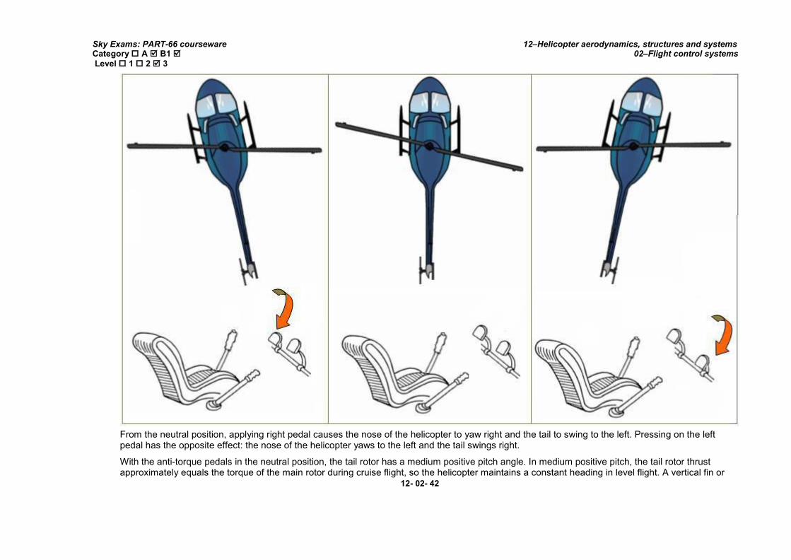
From the neutral position, applying right pedal causes the nose of the helicopter to yaw right and the tail to swing to the left. Pressing on the left pedal has the opposite effect: the nose of the helicopter yaws to the left and the tail swings right.
With the anti-torque pedals in the neutral position, the tail rotor has a medium positive pitch angle. In medium positive pitch, the tail rotor thrust approximately equals the torque of the main rotor during cruise flight, so the helicopter maintains a constant heading in level flight. A vertical fin or
12- 02- 42

Sky Exams: PART-66 courseware Category A B1 Level 1 2 3
12–Helicopter aerodynamics, structures and systems 02–Flight control systems
Stabilizer is used in many single-rotor helicopters to help aid in heading control. The fin is designed to optimize directional stability in flight with a zero tail rotor thrust setting. The size of the fin is crucial to this design. If the surface is too large, the tail rotor thrust may be blocked.
Helicopters that are designed with tandem rotors do not have an anti-torque rotor. These helicopters are designed with both rotor systems rotating in opposite directions to counteract the torque rather than a tail rotor.
2.3. Fenestron tail rotor systems:
The fenestron tail rotor is another relatively new technique that was patented by Eurocopter. The fenestron, pictured below, is essentially the same concept as a conventional tail rotor. Both systems feature spinning blades that generate a thrust force to cancel out the tendency of a helicopter fuselage to rotate.
Typical tail rotor fenestron
However, the fenestron rotor differs from a conventional rotor by adding several more blades. Whereas a conventional tail rotor seldom has more than four blades, a typical fenestron includes eight to thirteen blades.
Compared to conventional tail rotor blades, the fenestron blades are also much smaller and spin at higher speeds. Furthermore, these blades are mounted within a shroud that forms part of the vertical tail fin of the helicopter.
12- 02- 43

Sky Exams: PART-66 courseware Category A B1 Level 1 2 3
12–Helicopter aerodynamics, structures and systems 02–Flight control systems
This configuration turns the rotor into a ducted fan whose blade tips are protected from the external air.
The only significant drawback to ducted fans like the fenestron is that the shroud adds weight that offsets at least some of the improvements in performance.
Regardless of the weight penalty, noise reduction was one of the primary reasons a ducted fan system was adopted for the now-cancelled RAH-66 Comanche stealth helicopter pictured above.
RAH-66 Comanche
The primary advantage of this ducted fan arrangement is to reduce the turbulence and vortex shedding that occurs on rotor and propeller blades. In so doing, the rotor becomes more aerodynamically efficient by reducing drag, and noise as well as vibration is also significantly reduced. The fenestron offers safety advantages too since the shroud helps protect the rotor from striking outside objects.
12- 02- 44
Sky Exams: PART-66 courseware Category A B1 Level 1 2 3
12–Helicopter aerodynamics, structures and systems 02–Flight control systems
Tail rotor strikes against trees, powerlines, and other obstructions are one of the most common causes of helicopter crashes, so reducing the rotor's vulnerability to damage is important. The shroud also reduces the danger tail rotors have traditionally posed to ground crew operating near helicopters during takeoff and landing.
Since the majority of the noise generated by a helicopter tends to come from the tail rotor, designers adopted a ducted fan to reduce noise levels and make the helicopter more difficult to detect. This rotor system was essentially a copy of the French Fenestron yet was referred to by the name Fan tail in the US.
2.4. Tail rotor control systems:
Tail rotor control systems can be of two types: cable systems or push/pull tube systems.
In earlier helicopters cable systems were used because of the need to reduce the weight of the longer system, cable systems offering a weight saving of approximately 25-30% over tube systems.
However, cable systems suffer from several disadvantages, they require strengthening of the structure because of the relatively high cable tensions, and the steel cables will expand and contract at a different rate to the light alloy structure.
Whilst the latter was overcome with the use of cable tension regulators, cable systems still required more maintenance, and were prone to developing faults. Many modern helicopters, especially the larger types, now use push/pull tube systems for tail rotor control.
Cable systems:
The majority of cable systems use push/pull tubes from the yaw pedals to a cable quadrant, from here control cables are used to transfer control inputs through the fuselage and tail boom structure.
In very early helicopters the cables were wound around a cable spool, usually 1½ to 2½ turns, which was connected directly to a mechanical screw-jack that turned the motion through 90° and provided the movement to the tail rotor, via a spider mechanism, although this provided a purely manual control system and was generally only used on the light helicopter types.
An alternative to this, especially where hydraulic controls were used, was to position another quadrant just before the tail rotor, and connect it via a push/pull tube to the tail rotor control mechanism, or hydraulic actuator. One of the quadrants would be a cable tension regulator, ensuring consistent cable tensions.
Cables used in a system that used a cable spool could either be of the ‘continuous loop’ type or would have nipples swaged onto the ends of the cable. Those systems using 2 quadrants would comprise of 2 cables, having swaged nipples at each end to ensure positive retention at the quadrants.
Push/pull tube systems:
12- 02- 45

Sky Exams: PART-66 courseware Category A B1 Level 1 2 3
12–Helicopter aerodynamics, structures and systems 02–Flight control systems
In this system, the tubes transfer control inputs from the yaw pedals right through to the tail rotor control mechanism or actuator. Push/pull tube systems are more difficult to route than cables, and are comprised of many more components, many of which could potentially develop faults, but there is less possibility of lost motion developing rapidly within the system, as could be the case if control cables lost tension.
3. TWIN NON-COAXIAL ROTORS:
3.1. Tandem rotors:
If you are going to build a large helicopter for lifting heavy loads, then it makes sense to use two separate rotors to generate more lifting force. If these rotors are separate, such as those on the CH-46 Sea Knight, then they are called "non-coaxial," meaning they do not share the same axis.
Tandem twin non-coaxial rotors
The arrangement as a tandem rotor is mainly used with big helicopters. Because of the opposite rotation of the rotors, the torque of each single rotor will be neutralized. The construction of the control system is much more complicated, compared to a helicopter with a tail rotor.
The control along the vertical axis during hover flight is done by bending the rotor discs against each other.
12- 02- 46

Sky Exams: PART-66 courseware Category A B1 Level 1 2 3
12–Helicopter aerodynamics, structures and systems 02–Flight control systems
TandemCH-46 Sea Knight helicopter
Since these helicopters have two rotors that are usually equal in size, the simple solution to the yaw control problem is to spin the rotors in opposite directions. Thus, the yaw forces created by each rotor cancel each other out.
Yaw control is achieved by tilting the rotors in opposite directions (to the left and right in the case of the CH-46).
The two rotors are linked by a transmission that ensures the rotors are synchronized and do not hit each other, even during an engine failure. Tandem rotor designs achieve yaw by applying opposite left and right cyclic to each rotor, effectively pulling both ends of the helicopter in opposite directions.
To achieve pitch, opposite collective is applied to each rotor; decreasing the lift produced at one end, while increasing lift at the opposite end, effectively tilting the helicopter forward or back.
Advantages of the tandem-rotor system are; a larger centre-of-gravity range and good longitudinal stability.
Disadvantages of the tandem-rotor system are; a complex transmission and the need for two large rotors.
3.2. Side-by-side rotors:
The arrangement of two rotors side by side was not very popular. This is a large, twin-rotor cargo helicopter with 4 seats and plenty of space for hauling debris, landed capsules, rovers, spacecraft and what not. It is based on the real largest helicopter ever built.
12- 02- 47

Sky Exams: PART-66 courseware Category A B1 Level 1 2 3
12–Helicopter aerodynamics, structures and systems 02–Flight control systems
3.3. Twin intermeshing rotors:
MILMI-12
Like the tandem rotor, this configuration doesn't need a tail rotor, because the torque is compensated by the opposite rotation of the rotors. This system was developed during the early days of helicopter flying, but fell into oblivion.
12- 02- 48

Sky Exams: PART-66 courseware Category A B1 Level 1 2 3
12–Helicopter aerodynamics, structures and systems 02–Flight control systems
The principles by which intermeshing rotors operate are the same as those previously discussed for other twin rotor helicopters.
The difference is that the rotors are mounted very close together and actually intermesh; the blades on one rotor travel through the rotor disk of the other rotor.
Of course, the intermeshing of the rotors is carefully timed to keep the rotors from chopping each other to pieces.
Twin intermeshing rotors
Today this kind of arrangement of the rotor has been rediscovered and used with the Kaman K-MAX, a single seat helicopter, mainly used for external load transportation.
A subgroup of twin non-coaxial rotors is the twin intermeshing rotor system, seen only on a few helicopters made by the Kaman Company, including the H-43 Husky and K-MAX.
12- 02- 49

Sky Exams: PART-66 courseware Category A B1 Level 1 2 3
12–Helicopter aerodynamics, structures and systems 02–Flight control systems
H-43 Husky helicopter
3.4. Twin coaxial rotors:
Another yaw control strategy pioneered by the Russian manufacturer Kamov utilizes two rotors that share the same axis (coaxial), an example being the Ka-50.
Much like the non-coaxial design, the rotors rotate in opposite directions, each one counteracting the yaw force of the other. Yaw control is achieved by increasing the blade pitch on one rotor while decreasing the pitch on the other. The result is a differential in torque, resulting in a yawing motion. The most notable advantage of the twin coaxial arrangement is that it is very compact.
12- 02- 50

Sky Exams: PART-66 courseware Category A B1 Level 1 2 3
12–Helicopter aerodynamics, structures and systems 02–Flight control systems
Although the twin rotor configuration tends to be rather tall, the lack of a long tail boom results in a very short fuselage that takes up much less space. For this reason, Kamov designs have proven very popular for ship board use with the Russian Navy.
Twin coaxial rotor configuration
The control along the vertical axe occurs as a result of different lifts of the two rotor discs.
Depending on which rotor produces more lift, the helicopter will turn to the left or right, because of the torque. For these helicopters it is not possible to reach a high cruising speed, because the drag is too large. Only after the development of the rigid rotor, has it been possible to build the two rotors closer together and reduce the drag considerably.
12- 02- 51

Sky Exams: PART-66 courseware Category A B1 Level 1 2 3
12–Helicopter aerodynamics, structures and systems 02–Flight control systems
KamovKA-50
12- 02- 52

Sky Exams: PART-66 courseware Category A B1 Level 1 2 3
12–Helicopter aerodynamics, structures and systems 02–Flight control systems
4. BLEED AIR–NOTAR HELICOPTERS:
4.1. NOTAR® concept:
NOTAR system circulation control
12- 02- 53

Sky Exams: PART-66 courseware Category A B1 Level 1 2 3
12–Helicopter aerodynamics, structures and systems 02–Flight control systems
By far the most recent yaw control strategy developed for helicopters is the NO TAil Rotor (NOTAR) design. NOTAR was first developed by McDonnell Douglas during the 1980s and applied to a modified OH-6 Cayuse.
The concept proved so successful that the company began marketing dedicated NOTAR spin-offs of the successful MD500 family including the MD520 N.
The NOTAR system utilizes boundary layer control to provide anti-torque from the main rotor.
Two circulation control slots run along the starboard side of the tail boom, shown in figure. The result is that the tail boom acts like a wing flying in the downwash of the main rotor. This configuration produces 70 percent of the anti-torque in the hovering flight condition.
Directional control is obtained using a rotating thruster and twin rudders at the end of the tail boom.
In forward flight, the vertical stabilizers provide the majority of anti-torque, with the thruster once again used for directional control. Pilot inputs control the thruster nozzle and left vertical stabilizer.
The right vertical stabilizer moves under computer control from a gyro that senses the angular rotations of the aircraft in flight. A variable-pitch fan pressurizes the tail boom with a low pressure high volume of air. The fan is driven by a short shaft from the main engine. Consequently, the entire NOTAR assembly is comparable to a conventional tail rotor design.
Though the NOTAR arrangement still requires a long tail boom, the need for a spinning tail rotor is eliminated. This reduces the danger to ground crew, and also allows the pilot to maneuver into positions that he or she normally would not even consider.
For example, NOTAR allows a pilot to stick the tail boom into a tree. Try that with a standard tail rotor, and it will be time for an unscheduled landing.
We hope that this in-depth discussion satisfies any questions you might have about helicopter tail rotors. Of course, someone might come up with a better, simpler way of counteracting the force of the main rotor in a few years.
The NOTARs large screened air inlet to the fan causes reduced interaction effects than the conventional tail design since it is located near the rotor hub and subsequently has lower power requirements.
For helicopters with tail rotors that sit at or above the main rotor (which is the case form any larger helicopters), the difference in power requirements between the NOTAR design and the conventional design is negligible since the tail rotor now has a reduced interaction effect with the main rotor.
4.2. NOTAR® system operation:
The pilot and co-pilot yaw pedals control both the position of the jet-thruster and the pitch angle of the ducted fan, thereby allowing the correct amount of anti-torque force to be applied, without drawing too much power from the transmission system, as would be the case if the ducted fan was set at constant pitch and speed.
12- 02- 54

Sky Exams: PART-66 courseware Category A B1 Level 1 2 3
12–Helicopter aerodynamics, structures and systems 02–Flight control systems
MD-500 helicopter
Additionally, the yaw pedals also control the angle of the vertical stabilisers fitted to the rear of the tail boom, which have a maximum deflection of 29 degrees, which unload the jet-thruster and ducted fan during forward flight, making more power available for the main rotor, with a reduction in fuel consumption.
12- 02- 55
Sky Exams: PART-66 courseware Category A B1 Level 1 2 3
12–Helicopter aerodynamics, structures and systems 02–Flight control systems
In the hover, the Coanda effect produced by the circulation control slots provides the majority of the anti-torque force, whilst during forward flight this is produced by the vertical stabilisers and jet-thruster. During autorotation with the engine shutdown directional control is provided by the vertical stabilisers.
Ducted fan: A large ducted fan, driven by the main rotor transmission, is mounted in the rear of the fuselage; this provides a flow of
low pressure air through a large diameter hollow tail boom, which is made from composite materials.
Ontheendofthetailboomisavariablejet-thrustercontrolledbythepilotandco-pilot yaw pedals, this thrusters opens and closes in response to control inputs to provide a greater or lesser anti-torque force.
Coanda effect: The large diameter hollow tail boom has 2 slots manufactured into its side, known as circulation control slots.
A percentage of the air flowing through the boom exits through these slots and causes the air flowing in the downwash from the main rotor to adhere to one side longer than the other, in effect producing a vertical aerofoil section, and thus producing a side force to oppose torque reaction.
12- 02- 56

Sky Exams: PART-66 courseware Category A B1 Level 1 2 3
12–Helicopter aerodynamics, structures and systems 02–Flight control systems
VI. MAIN ROTOR HEAD–DESIGN AND OPERATION FEATURES
1. INTRODUCTION:
The rotor system is the rotating part of a helicopter which generates lift. The rotor consists of a mast, hub, and rotor blades. The mast is a hollow cylindrical metal shaft which extends upwards from and is driven and sometimes supported by the transmission. At the top of the mast is the attachment point for the rotor blades called the hub. The rotor blades are then attached to the hub by any number of different methods.
Main rotor systems are classified according to how the main rotor blades are attached and move relative to the main rotor hub. There are three basic classifications:
Semi rigid,
rigid, or
fully articulated.
Some modern rotor systems, such as the bearing less rotor system, use an engineered combination of these types. The choice of which main rotor head type is used on individual helicopter types is made by consideration of several factors, which is mainly based upon aerodynamic considerations; there are however, both advantages and disadvantages for each group, which are discussed in the following paragraphs.
2. COMPARISON OF MAIN ROTOR TYPES:
The most common main rotor types in use today are the fully articulated and semi-rigid, but these definitions were produced in the earliest days of helicopter manufacture. In recent times it has been the practice to utilise features from one main rotor type on another, and the actual group that any modern main rotor head falls into can now be more difficult to define, especially since the introduction of elastomeric components, which are now very common. In general terms, it is easiest to define the three groupings by the constructional arrangement of the main rotor head, which are generally defined as follows:
Rigid: A main rotor head that has no facility for the rotor blades to flap or drag.
Semi rigid: A main rotor head incorporating a flapping hinge, or other device that allows flapping.
Fully articulated: A main rotor incorporating flapping hinges and drag or lead/lag hinges.
Each of these main rotor head types will, of course, incorporate feathering bearings, to allow for rotor blade pitch changes, and therefore these are excluded from the definitions.
Whilst these are workable definitions, they are by no means always accurate, for example the Westland Lynx helicopter has a main rotor described as being semi rigid, and yet it provides a limited facility for the rotor blades to flap and drag.
12- 02- 57
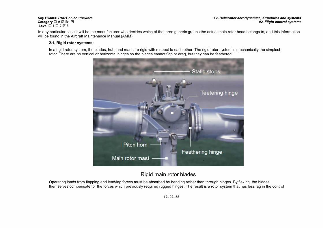
Sky Exams: PART-66 courseware Category A B1 Level 1 2 3
12–Helicopter aerodynamics, structures and systems 02–Flight control systems
In any particular case it will be the manufacturer who decides which of the three generic groups the actual main rotor head belongs to, and this information will be found in the Aircraft Maintenance Manual (AMM).
2.1. Rigid rotor systems:
In a rigid rotor system, the blades, hub, and mast are rigid with respect to each other. The rigid rotor system is mechanically the simplest rotor. There are no vertical or horizontal hinges so the blades cannot flap or drag, but they can be feathered.
Rigid main rotor blades
Operating loads from flapping and lead/lag forces must be absorbed by bending rather than through hinges. By flexing, the blades themselves compensate for the forces which previously required rugged hinges. The result is a rotor system that has less lag in the control
12- 02- 58

Sky Exams: PART-66 courseware Category A B1 Level 1 2 3
12–Helicopter aerodynamics, structures and systems 02–Flight control systems
response, because the rotor has much less oscillation. The rigid rotor system also negates the danger of mast bumping inherent in semi-rigid rotors.
Four-blade rigid main rotor.
The rigid rotor system shown in next figure is mechanically simple, but structurally complex because operating loads must be absorbed in bending rather than through hinges. In this system, the blade roots are rigidly attached to the rotor hub.
In this example, blades are comprised of glass fiber reinforced material. The hub is a single piece of forged rigid titanium.
12- 02- 59
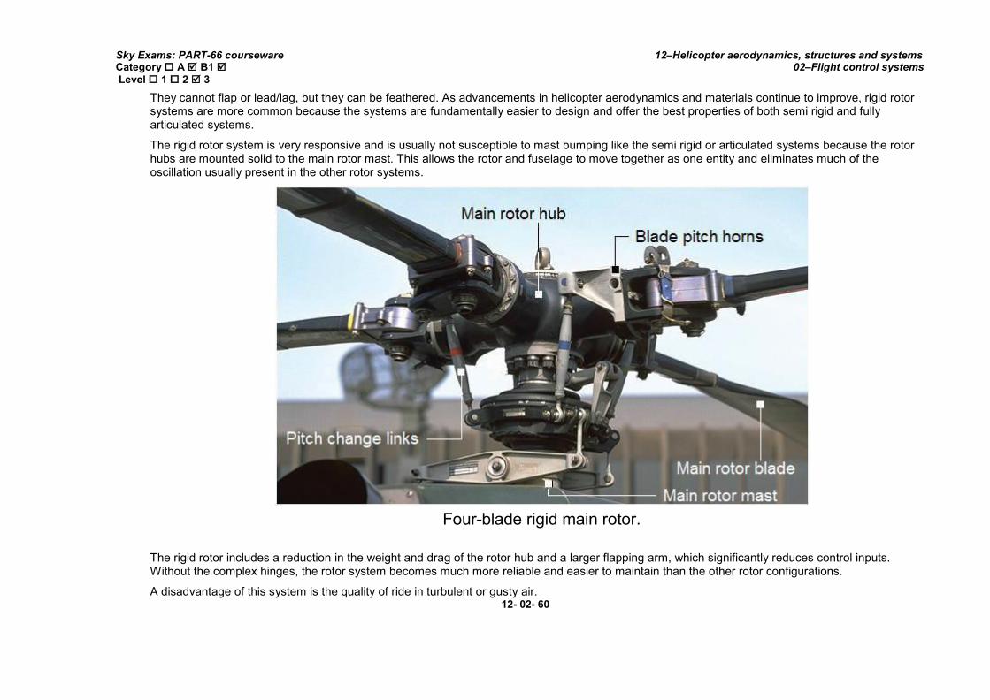
Sky Exams: PART-66 courseware Category A B1 Level 1 2 3
12–Helicopter aerodynamics, structures and systems 02–Flight control systems
They cannot flap or lead/lag, but they can be feathered. As advancements in helicopter aerodynamics and materials continue to improve, rigid rotor systems are more common because the systems are fundamentally easier to design and offer the best properties of both semi rigid and fully articulated systems.
The rigid rotor system is very responsive and is usually not susceptible to mast bumping like the semi rigid or articulated systems because the rotor hubs are mounted solid to the main rotor mast. This allows the rotor and fuselage to move together as one entity and eliminates much of the oscillation usually present in the other rotor systems.
Four-blade rigid main rotor.
The rigid rotor includes a reduction in the weight and drag of the rotor hub and a larger flapping arm, which significantly reduces control inputs. Without the complex hinges, the rotor system becomes much more reliable and easier to maintain than the other rotor configurations.
A disadvantage of this system is the quality of ride in turbulent or gusty air. 12- 02- 60
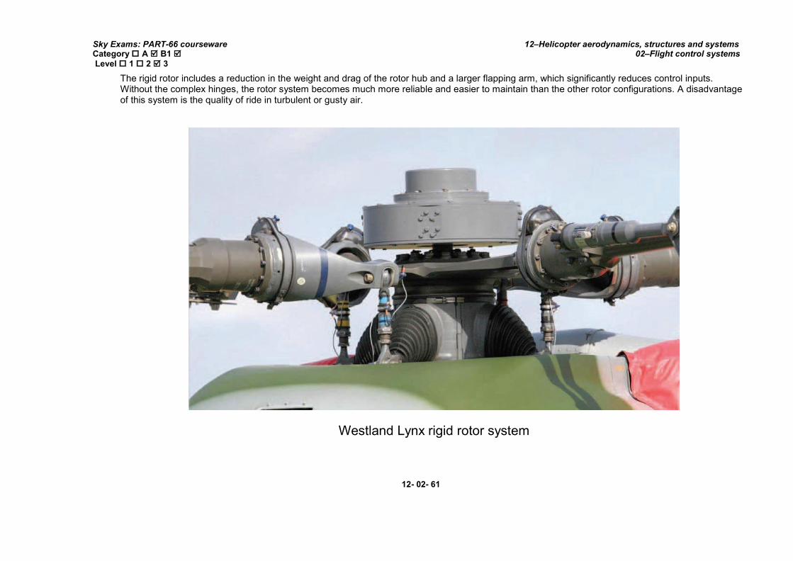
Sky Exams: PART-66 courseware Category A B1 Level 1 2 3
12–Helicopter aerodynamics, structures and systems 02–Flight control systems
The rigid rotor includes a reduction in the weight and drag of the rotor hub and a larger flapping arm, which significantly reduces control inputs. Without the complex hinges, the rotor system becomes much more reliable and easier to maintain than the other rotor configurations. A disadvantage of this system is the quality of ride in turbulent or gusty air.
Westland Lynx rigid rotor system
12- 02- 61

Sky Exams: PART-66 courseware Category A B1 Level 1 2 3
12–Helicopter aerodynamics, structures and systems 02–Flight control systems
Main rotor blade attachment joint on rigid main rotor system
Because there are no hinges to help absorb the larger loads, vibrations are felt in the cabin much more than with other rotor head designs. There are several variations of the basic three rotor head designs. The bearing less rotor system is closely related to the articulated rotor system, but has no bearings or hinges.
This design relies on the structure of blades and hub to absorb stresses.
12- 02- 62
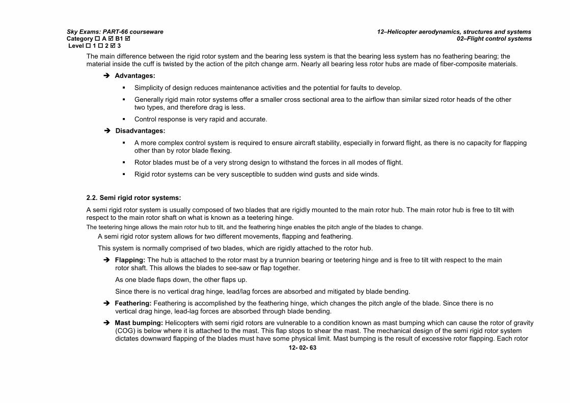
Sky Exams: PART-66 courseware Category A B1 Level 1 2 3
12–Helicopter aerodynamics, structures and systems 02–Flight control systems
The main difference between the rigid rotor system and the bearing less system is that the bearing less system has no feathering bearing; the material inside the cuff is twisted by the action of the pitch change arm. Nearly all bearing less rotor hubs are made of fiber-composite materials.
Advantages:
Simplicity of design reduces maintenance activities and the potential for faults to develop.
Generally rigid main rotor systems offer a smaller cross sectional area to the airflow than similar sized rotor heads of the other two types, and therefore drag is less.
Control response is very rapid and accurate.
Disadvantages:
A more complex control system is required to ensure aircraft stability, especially in forward flight, as there is no capacity for flapping other than by rotor blade flexing.
Rotor blades must be of a very strong design to withstand the forces in all modes of flight.
Rigid rotor systems can be very susceptible to sudden wind gusts and side winds.
2.2. Semi rigid rotor systems:
A semi rigid rotor system is usually composed of two blades that are rigidly mounted to the main rotor hub. The main rotor hub is free to tilt with respect to the main rotor shaft on what is known as a teetering hinge.
The teetering hinge allows the main rotor hub to tilt, and the feathering hinge enables the pitch angle of the blades to change.
A semi rigid rotor system allows for two different movements, flapping and feathering.
This system is normally comprised of two blades, which are rigidly attached to the rotor hub.
Flapping: The hub is attached to the rotor mast by a trunnion bearing or teetering hinge and is free to tilt with respect to the main
rotor shaft. This allows the blades to see-saw or flap together.
As one blade flaps down, the other flaps up.
Since there is no vertical drag hinge, lead/lag forces are absorbed and mitigated by blade bending.
Feathering: Feathering is accomplished by the feathering hinge, which changes the pitch angle of the blade. Since there is no
vertical drag hinge, lead-lag forces are absorbed through blade bending.
Mast bumping: Helicopters with semi rigid rotors are vulnerable to a condition known as mast bumping which can cause the rotor of gravity (COG) is below where it is attached to the mast. This flap stops to shear the mast. The mechanical design of the semi rigid rotor system dictates downward flapping of the blades must have some physical limit. Mast bumping is the result of excessive rotor flapping. Each rotor
12- 02- 63

Sky Exams: PART-66 courseware Category A B1 Level 1 2 3
12–Helicopter aerodynamics, structures and systems 02–Flight control systems
system design has a maximum flapping angle. If flapping exceeds the design value, the static stop will contact the mast. It is the violent contact between the static stop and the mast during flight that causes mast damage or separation. This contact must be avoided at all costs.
Bell 230 semi rigid rotor
12- 02- 64
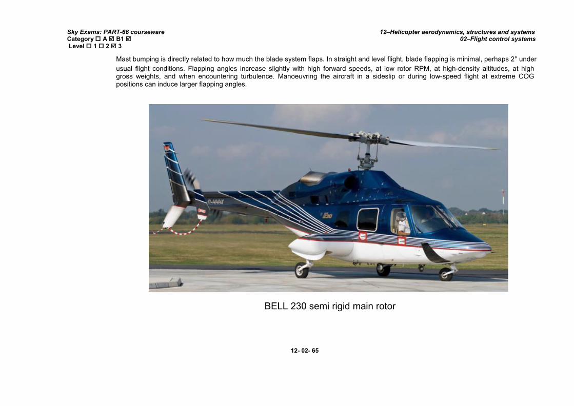
Sky Exams: PART-66 courseware Category A B1 Level 1 2 3
12–Helicopter aerodynamics, structures and systems 02–Flight control systems
Mast bumping is directly related to how much the blade system flaps. In straight and level flight, blade flapping is minimal, perhaps 2° under
usual flight conditions. Flapping angles increase slightly with high forward speeds, at low rotor RPM, at high-density altitudes, at high gross weights, and when encountering turbulence. Manoeuvring the aircraft in a sideslip or during low-speed flight at extreme COG positions can induce larger flapping angles.
BELL 230 semi rigid main rotor
12- 02- 65

Sky Exams: PART-66 courseware Category A B1 Level 1 2 3
12–Helicopter aerodynamics, structures and systems 02–Flight control systems
Underslung rotor: The underslung rotor system mitigates the lead/lag forces by mounting the blades slightly lower than the usual plane of rotation, so the lead and lag forces are minimized. As the blades cone upward, the centre of pressures of the blades are almost in the same plane as the hub. Whatever stresses are remaining bend the blades for compliance.
If the semi rigid rotor system is an underslung rotor, the centre of gravity (COG) is below where it is attached to the mast. This underslung mounting is designed to align the blades centre of mass with a common flapping hinge so that both blades centres of mass vary equally in distance from the centre of rotation during flapping. The rotational speed of the system tends to change, but this is restrained by the inertia of the engine and flexibility of the drive system. Only a moderate amount of stiffening at the blade root is necessary to handle this restriction.
Simply put, underslinging effectively eliminates geometric imbalance.
Advantages:
The elimination of individual flapping hinges and dragging hinges simplifies construction, and eliminates many faults, particularly those that increase vibration levels, associated with fully articulated rotor heads.
Because of the simplicity of design, maintenance can be made more simple and less time consuming.
The rotor blades are fixed to the main rotor hub and do not usually rely upon centrifugal force for rigidity.
The reduction in components also reduces the weight and drag producing characteristics when compared to the larger and more complex fully articulated main rotor heads.
Disadvantages:
Sudden wind gusts can cause instability, because of an inability, or limited ability for individual rotor blades to flap.
Because of the lack of flapping and dragging hinges, greater bending forces are applied to the rotor blade roots and attachments. The rotor blades must be designed with sufficient strength to withstand these greater forces, increasing their weight.
Teetering type semi-rigid main rotor heads need to be underslung to minimize Coriolis effect when the rotor ‘seesaws’.
2.3. Fully articulated rotor system:
In a fully articulated rotor system, each rotor blade is attached to the rotor hub through a series of hinges, which allow the blade to move independently of the others. These rotor systems usually have three or more blades.
The blades are allowed to flap, feather, and lead or lag independently of each other.
Horizontal(flapping) hinge: The horizontal hinge, called the flapping hinge, allows the blade to move up and down. This movement is designed to compensate for dissymmetry of lift. The flapping hinge may be located at varying distances from the rotor hub, and there may be more than one hinge.
12- 02- 66

Sky Exams: PART-66 courseware Category A B1 Level 1 2 3
12–Helicopter aerodynamics, structures and systems 02–Flight control systems
Fully articulated rotor systems allow each blade to lead/lag (move back and forth in plane),flap (move up and down about an inboard mounted hinge) independent of the other blades, and feather (rotate about the pitch axis to change lift).
The flapping hinge for the blade permits this motion and is balanced by the centrifugal force of the weight of the blade, which tries to keep it in the horizontal plane. The centrifugal force is nominally constant; however, the flapping force is affected by the severity of the maneuver (rate of climb, forward speed, aircraft gross weight). As the blade flaps, its COG changes.
These changes the local moment of inertia of the blade with respect to the rotor system and it speeds up or slows down with respect to the rest of the blades and the whole rotor system. This is accommodated by the lead/lag or drag hinge. This is also known as the conservation of angular momentum. An in-plane damper typically moderates lead/lag motion.
Fully articulated flapping hub
Vertical(drag) hinge: The vertical hinge, also called the lead-lag or drag hinge, allows the blade to move back and forth. This movement is
called lead-lag, dragging, or hunting. Dampers are usually used to prevent excess back and forth movement around the drag hinge.
The purpose of the drag hinge and dampers is to compensate for the acceleration and deceleration caused by Coriolis Effect. Each blade can also be feathered, that is, rotated around its spanwise axis. Feathering the blade means changing the pitch angle of the blade.
By changing the pitch angle of the blades you can control the thrust and direction of the main rotor disc.
12- 02- 67

Sky Exams: PART-66 courseware Category A B1 Level 1 2 3
12–Helicopter aerodynamics, structures and systems 02–Flight control systems
Fully articulated main rotor principle
Each blade of a fully articulated rotor system can flap, drag, and feather independently of the other blades
12- 02- 68

Sky Exams: PART-66 courseware Category A B1 Level 1 2 3
12–Helicopter aerodynamics, structures and systems 02–Flight control systems
Fully articulated rotor movements
As the rotor spins, each blade responds to inputs from the control system to enable aircraft control. The centre of lift on the whole rotor system moves in response to these inputs to effect pitch, roll, and upward motion.
The magnitude of this lift force is based on the collective input, which changes pitch on all blades in the same direction at the same time. The location of this lift force is based on the pitch and roll inputs from the pilot.
Fully articulated rotor systems are found on helicopters with more than two main rotor blades.
12- 02- 69
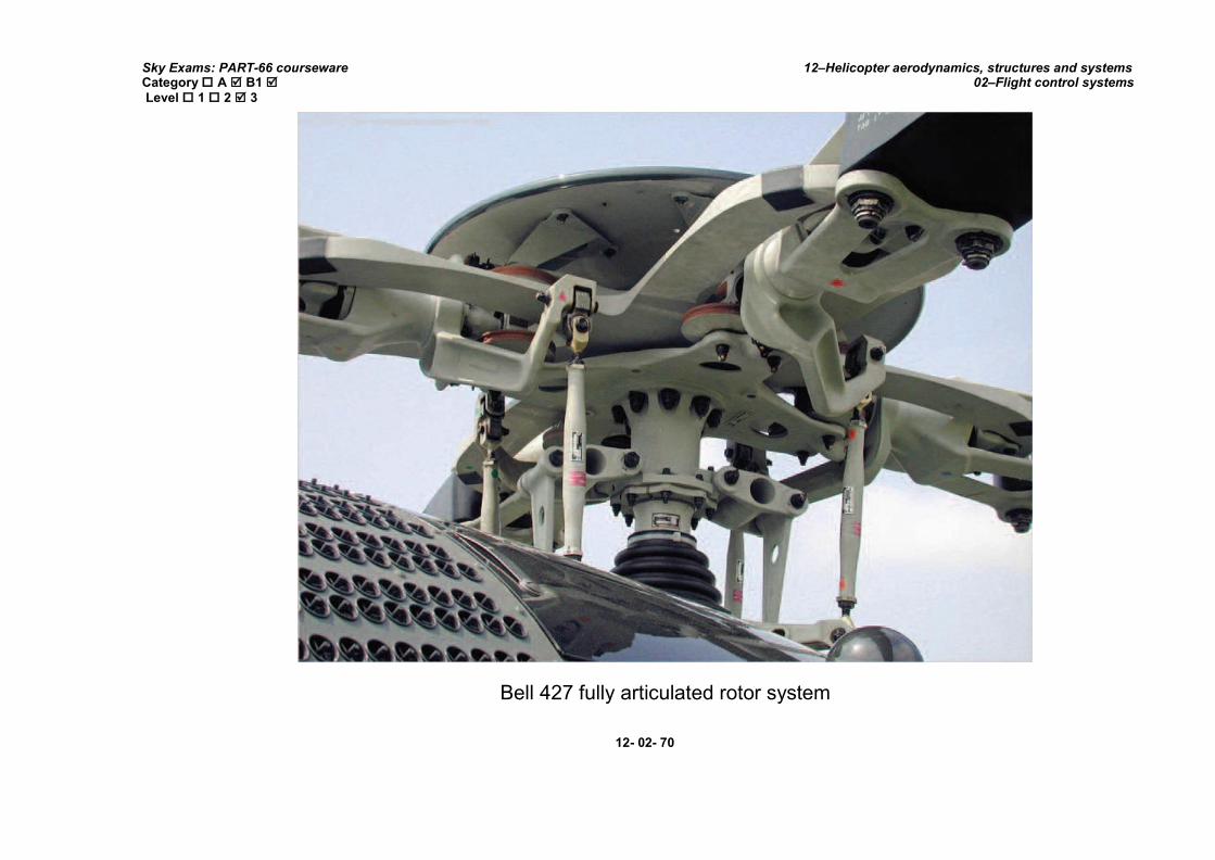
Sky Exams: PART-66 courseware Category A B1 Level 1 2 3
12–Helicopter aerodynamics, structures and systems 02–Flight control systems
Bell 427 fully articulated rotor system
12- 02- 70
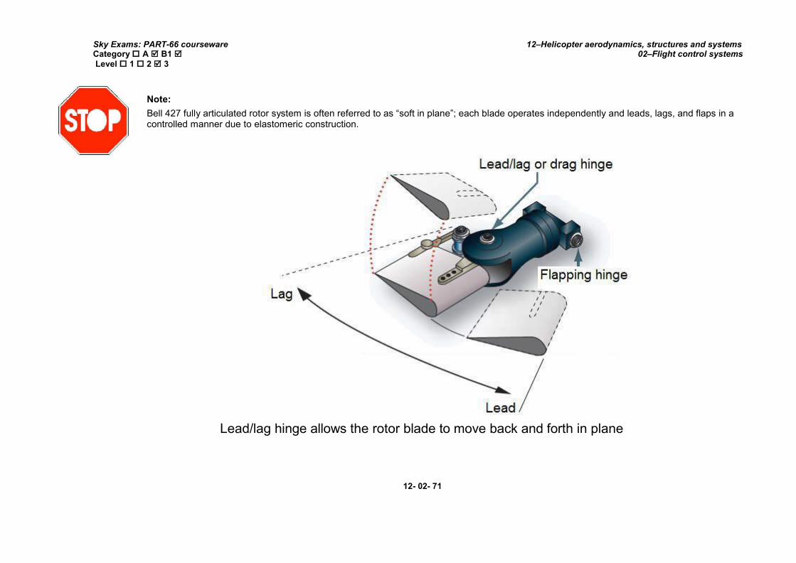
Sky Exams: PART-66 courseware Category A B1 Level 1 2 3
12–Helicopter aerodynamics, structures and systems 02–Flight control systems
Note:
Bell 427 fully articulated rotor system is often referred to as “soft in plane”; each blade operates independently and leads, lags, and flaps in a controlled manner due to elastomeric construction.
Lead/lag hinge allows the rotor blade to move back and forth in plane
12- 02- 71

Sky Exams: PART-66 courseware Category A B1 Level 1 2 3
12–Helicopter aerodynamics, structures and systems 02–Flight control systems
Drag hinge allows the rotor blade to move back and forth in plane
Elastomeric bearings:
Newer rotor systems use elastomeric bearings, arrangements of rubber and steel that can permit motion in two axes. Besides solving some of the above mentioned kinematic issues, these bearings are usually in compression, can be readily inspected, and eliminate the maintenance associated with metallic bearings.
Elastomeric bearings are naturally fail-safe and their wear is gradual and visible. The metal-to-metal contact of older bearings and the need for lubrication is eliminated in this design.
12- 02- 72

Sky Exams: PART-66 courseware Category A B1 Level 1 2 3
12–Helicopter aerodynamics, structures and systems 02–Flight control systems
2.4. Combination rotor system:
EC-725 main rotor with elastomeric bearings
Modern rotor systems may use the combined principles of the rotor systems mentioned above. Some rotor hubs incorporate a flexible hub, which allows for blade bending (flexing) without the need for bearings or hinges. These systems, called “Flextures”, are usually constructed from composite material.
Elastomeric bearings may also be used in place of conventional roller bearings. Elastomeric bearings are bearings constructed from a rubber type material and have limited movement that is perfectly suited for helicopter applications. Flextures and elastomeric bearings require no lubrication and, therefore, require less maintenance. They also absorb vibration, which means less fatigue and longer service life for the helicopter components. Combination rotor systems, such as Bell’s soft-in-plane, use composite material and elastomeric bearing to reduce complexity and maintenance. These systems increase the reliability.
12- 02- 73

Sky Exams: PART-66 courseware Category A B1 Level 1 2 3
12–Helicopter aerodynamics, structures and systems 02–Flight control systems
Bell 412 Arapaho(CH-146 Griffon)
The terms soft-in-plane and stiff-in-plane are use to compare lead-lag frequency, in the plane of rotation, to the shaft rotational frequency. If it's soft-in-plane the lead-lag frequency is normally less than the shaft rotational frequency (soft follower of the shaft rotational)
In this example, the CH-146 Griffon has four-blade hingeless flex-beam soft-in-plane main rotor. Hub is composed of two titanium flex-beam yokes, four steel spindles with grip lugs for blade attachment, and elastomeric bearings and dampers. A mechanical pendulum dampers is mounted on leading and trailing edges to absorb the vibrations.
12- 02- 74

Sky Exams: PART-66 courseware Category A B1 Level 1 2 3
12–Helicopter aerodynamics, structures and systems 02–Flight control systems
AgustaWestlandAW-139
AW-139 has a fully articulated main rotor with five composite blades, five elastomeric bearings and five hydraulic dampers.
2.5. Bearingless Main Rotors (BMR technology):
During the past three decades, the helicopter industry has invested a very substantial amount of resources in the development of production hingeless and bearingless rotor systems.
Bearingless rotor systems, such as the Eurocopter systems, have contact surfaces or load points made of elastomeric composite components that deform and twist to allow blade movement.
The hingeless (bearingless) rotor system functions much as the articulated system does, but uses elastomeric bearings and composite flextures to allow flapping and lead lag movements of the blades in place of conventional hinges.
12- 02- 75

Sky Exams: PART-66 courseware Category A B1 Level 1 2 3
12–Helicopter aerodynamics, structures and systems 02–Flight control systems
It’s advantages are improved control response with less lag and substantial improvements in vibration control. It does not have the risk of ground resonance associated with the articulated type unless the landing gear system needs servicing. The hingeless rotor system is also considerably a more expensive system.
Eurocopter EC-135 main rotor (Spheri-flex BMR technology)
Most of these components are “on-condition” life items versus metal components which must be changed at certain times due to metal fatigue. The composite components are designed so that even if a portion fails, the aircraft can make a safe landing.
12- 02- 76

Sky Exams: PART-66 courseware Category A B1 Level 1 2 3
12–Helicopter aerodynamics, structures and systems 02–Flight control systems
Hingeless rotored helicopters, such as the MBB BO-105, and the Westland Lynx have been in production for almost 25 years.
However, successful bearing less rotored helicopters have gone into production only during the last decade. Typical examples are the MD-900 Explorer, the Comanche bearing less main rotor, the Eurocopter EC135.
Eurocopter's star-flex and spheri-flex bearing less main rotor hubs ensure very fast response to pitch changes, while also offering excellent manoeuvrability and stability. Used across Eurocopter's helicopter product line, they have a fail-safe design through the application of composite materials, and are practically maintenance-free.
12- 02- 77

Sky Exams: PART-66 courseware Category A B1 Level 1 2 3
12–Helicopter aerodynamics, structures and systems 02–Flight control systems
VII. BLADE DAMPERS: FUNCTION AND CONSTRUCTION
1. ROTOR VIBRATIONS:
With the many rotating parts found in helicopters, some vibration is inherent. You need to understand the cause and effect of helicopter vibrations because abnormal vibrations cause premature component wear and may even result in structural failure.
With experience, you learn what vibrations are normal versus those that are abnormal and can then decide whether continued flight is safe or not. Helicopter vibrations are categorized into low, medium, or high frequency.
1.1. Low frequency vibrations:
Low frequency vibrations (100-500 cycles per minute) usually originate from the main rotor system. The vibration may be felt through the controls, the airframe, or a combination of both. Furthermore, the vibration may have a definite direction of push or thrust. It may be vertical, lateral, horizontal, or even a combination.
Normally, the direction of the vibration can be determined by concentrating on the feel of the vibration, which may push you up and down, backwards and forwards, or from side to side. The direction of the vibration and whether it is felt in the controls or the airframe is an important means for the mechanic to troubleshoot the source. Some possible causes could be that the main rotor blades are out of track or balance, damaged blades, worn bearings, dampers out of adjustment, or worn parts.
1.2. Medium and high frequency vibrations:
Medium frequency vibrations (1,000-2,000 cycles per minute) and high frequency vibrations (2,000 cycles per minute or higher) are normally associated without of-balance components that rotate at a high RPM, such as the tail rotor, engine, cooling fans, and components of the drivetrain, including transmissions, driveshafts, bearings, pulleys, and belts. Most tail rotor vibrations can be felt through the tail rotor pedals as long as there are no hydraulic actuators, which usually dampen out the vibration. Any imbalance in the tail rotor system is very harmful, as it can cause cracks to develop and rivets to work loose. Piston engines usually produce a normal amount of high frequency vibration, which is aggravated by engine malfunctions such as spark plug fouling, incorrect magneto timing, carburetor icing and/or incorrect fuel/air mixture. Vibrations in turbine engines are often difficult to detect as these engines operate at a very high RPM.
2. HELICOPTER GROUND AND AIR RESONANCE:
In whirling, the kinetic energy (KE) of the hub is constantly changing because the circular motion requires a constant change of velocity. It follows that the kinetic energy of the blades must also be changing constantly.
12- 02- 78

Sky Exams: PART-66 courseware Category A B1 Level 1 2 3
12–Helicopter aerodynamics, structures and systems 02–Flight control systems
12- 02- 79

Sky Exams: PART-66 courseware Category A B1 Level 1 2 3
12–Helicopter aerodynamics, structures and systems 02–Flight control systems
2.1. Ground resonance phenomenon:
The blade KE variation is due to motion of the blade centre of gravity (COG) plus that due to in-plane rotation of the moment of inertia of the blade about the null point. Essentially whirling is a continuous interplay of blade and hub energy and in the absence of friction at the hinges and any aerodynamic effect it could continue indefinitely.
Figure is in stationary co-ordinates. Figure (a) shows an articulated rotor turning anticlockwise and whirling forwards whereas (b) shows the same rotor which is still turning anticlockwise but which is whirling backwards.
A rotor turning anticlockwise with forward whirling. The reaction from the hull opposes the whirling.
A rotor turning anticlockwise with backward whirling. The reaction from the hull which is the same as in (a) is now in the same direction as the whirling and amplifies it. This is the mechanism of ground resonance.
2.2. Air resonance phenomenon:
Air resonance is a condition primarily relevant to helicopters having hingeless rotors.
In articulated rotors the natural frequency of the blade about the lagging hinge is low and lag dampers are in any case present to prevent ground resonance. Furthermore the motion of the hull is decoupled to some extent by the articulation. In a hingeless rotor the blades lag by flexing and the stiffness is higher, leading to a higher natural frequency of lagging motion.
The relatively stiff connection between the rotor and the hull means that large rotor moments can excite hull flexing.
If such hull flexing is resonant then an unstable system could exist. A bending mode of the hull could result in a lateral motion at the rotor head that is similar to the rocking experienced in ground resonance.
2.3. Ground (and air) resonance solutions:
In the absence of preventive measures, a helicopter on the ground with progressive backward rotor whirling is a mechanical oscillator. Given the huge amount of energy stored in the rotor, once started the whirling will increase in amplitude until something breaks. Hull rocking (ground) resonance can only occur if there is a reaction from the ground, hence the name of the phenomenon.
This also explains why a machine can fly safely but disintegrates on landing, as has happened on a number of occasions.
There are a number of solutions to ground resonance which will be explored. It will be seen from a consideration that damping any changes in the angle θ will be highly effective hence the use of dragging dampers in the traditional fully articulated rotor head.
In many cases damping is provided in the undercarriage to dissipate landing impacts and this damping can augment but not replace the damping in the head.
12- 02- 80

Sky Exams: PART-66 courseware Category A B1 Level 1 2 3
12–Helicopter aerodynamics, structures and systems 02–Flight control systems
In modern helicopters employing damping, ground resonance is virtually unknown provided the dampers are kept in good order. These dampers may be hydraulic, similar to automobile dampers, which work by forcing oil through a small orifice, or elastomeric, which work by dissipating heat in hysteretic flexing.
The latter have the advantage of needing no maintenance. Oil filled dampers will lose effectiveness if the oil leaks.
Given the destructive nature of ground resonance, it is a good idea to examine the dampers as part of the pre-flight inspection. By moving the blade on its dragging hinge, the resistance of the damper can be felt and the oil can be heard rushing through the damping orifice. All of the blades should feel and sound the same. If one blade feels different the damper may have some air in it. As the air is forced through the damping orifice the sound will change.
Whilst one weak damper may not cause ground resonance, it may result in an increase in vibration in forward flight. It is also useful to learn the characteristic of the machine’s padding on start-up. If the rotor dampers are satisfactory, but there is unusual padding, the undercarriage oleos may need attention.
A smoother rotor start may result if all of the blades are first moved to their rearward damper travel limit.
Unusual padding may also result if the machine is parked on a slope when gravity will tend to take the blades out of pattern during the early stages of starting.
2. DAMPER FUNCTION:
The main function of the damper is to slow the tendency of the blade to lag when the rotor is first started up or to lead when the rotor is slowed or the brake applied.
Dampers are usually used to prevent excess back and forth movement around the drag hinge. The purpose of the drag hinge and dampers is to compensate for the acceleration and deceleration caused by Coriolis effect.
They absorb the jolts and attenuate the blades vibrations during their revolution. There were several types, but some are not used anymore, like the damper with disc, friction or hydraulics with pallets.
On the other hand, the piston hydraulic dampers are still largely widespread.
In certain cases, dampers are doubled of blade spacing wires, on old design machines. The damper help keep the blades equally spaced and reduce the possibility of ground resonance.
2.1. Hydraulic dampers:
Hydraulic dampers rely upon throttled flow of fluids that generate damping forces proportional to the square of velocity. This can result in extremely high damping forces when amplitudes increase.
12- 02- 81

Sky Exams: PART-66 courseware Category A B1 Level 1 2 3
12–Helicopter aerodynamics, structures and systems 02–Flight control systems
Hydraulic dampers are prone to leakage problems and have a short life due to a large number of moving components and seal wear resulting in higher maintenance cost.
The weight and size of these dampers result in another penalty due to high parasitic load and aerodynamic drag.
Fully-articulated rotor and damper
2.2. Elastomeric dampers:
Elastomeric dampers employing bonded elastomeric material exhibit visco-elastic behavior under dynamic conditions, dissipating energy through hysteresis. These materials respond non-linearly to the amplitude of motion, frequency of motion, and temperature. Compared with
conventional
12- 02- 82

Sky Exams: PART-66 courseware Category A B1 Level 1 2 3
12–Helicopter aerodynamics, structures and systems 02–Flight control systems
Hydraulic dampers, elastomeric dampers are lighter in weight and have fewer parts. They do not have the sliding seals of hydraulic dampers and are not affected by sand and dust.
Elastomeric dampers exhibit gradual deterioration, detectable by visual inspection. These elastomers are rapidly gaining popularity as a solution for designing lag dampers with high damping capability, and have been utilized for articulated rotor systems; examples include the Eurocopter EC-135, the Boeing AH-64 Apache, the Boeing, CH-47 F Chinook, the Bell model 412, the Sikorsky RAH-66 Comanche, and the McDonnell Douglas Explorer.
An elastomeric damper is non linear and highly dependent on frequency, temperature and loading conditions such as preload and excitation amplitudes. The damping of an elastomer has been shown to degrade substantially at low amplitudes, causing undesirable limit cycle oscillations. Consequently, alternative methods for augmenting aeromechanical stability are explored.
Elastomeric inertial dampers
12- 02- 83

Sky Exams: PART-66 courseware Category A B1 Level 1 2 3
12–Helicopter aerodynamics, structures and systems 02–Flight control systems
Inertial dampers (Eurocopter EC-135 main rotor)
Advantages of elastomeric dampers:
Elastomeric dampers are generally self-lubricating,
Elastomeric dampers cannot seize,
They are not subject to faults such as brinelling, pitting or galling that conventional bearing suffer from,
12- 02- 84

Sky Exams: PART-66 courseware Category A B1 Level 1 2 3
12–Helicopter aerodynamics, structures and systems 02–Flight control systems
Less vibration and shock is transmitted to adjacent components,
Boots and seals are not required as no lubrication is required,
They contain fewer parts, and are generally bonded together, eliminating a potential loose article hazard,
They have better resistance to environmental conditions,
Generally elastomeric components have a life of at least 5 times that of conventional components,
They can be designed to take all loads and motion at a set point, eliminating the need for several bearings to be used in one location.
Disadvantages of elastomeric dampers:
The cost of elastomeric components tend to be much greater than similar conventional components,
The size is dependent upon the load to be taken, and elastomeric components can often be larger than the conventional component they replace,
They are susceptible to attack by strong chemicals and solvents, and require careful handling.
2.3. Variable dampers:
Current practice of adding passive damping may be improved to handle large dynamic range of the blade with several peaks of vibration resonance.
To minimize extra-large damping forces that may damage the control system of blade, passive dampers should have relatively small damping coefficients, which in turn limit the effectiveness.
By providing variable damping, a much larger damping coefficient to suppress the vibration can be realized. If the damping force reaches the maximum allowed threshold, the damper will be automatically switched into the mode with smaller damping coefficient to maintain near-constant damping force.
Furthermore, the proposed control system will also have a fail-safe feature to guarantee the basic preformation of a typical passive damper.
The proposed control strategy to avoid resonant regions in the frequency domain is to generate variable damping force in combination with the supporting stiffness to manipulate the restoring force and conservative energy of the controlled blade system.
Two control algorithms are developed and verified by a prototype variable damper, a digital controller and corresponding algorithms. Primary experiments show good potentials for the proposed variable damper: about 66% and 82% reductions in displacement at 1/3 length and the root of the blade respectively.
12- 02- 85

Sky Exams: PART-66 courseware Category A B1 Level 1 2 3
12–Helicopter aerodynamics, structures and systems 02–Flight control systems
2.4. Fluidfilled dampers:
Main rotor with variable dampers
Fluid filled dampers combine benefits of bonded elastomeric dampers such as simplicity, lightweight, reliability, energy storage capacity, multi-axis spring rate capability and maintenance free operation with the broader range of dynamic capability provided by non-toxic, non-corrosive fluids. These dampers are exclusively manufactured by the Lord Corporation under the trade name of fluidlastic.
Fluidlastic dampers enjoy several advantages over hydraulic dampers in the sense that they do not require dynamic seals, extremely close tolerances, plated surfaces and polished finishes on the components.
12- 02- 86

Sky Exams: PART-66 courseware Category A B1 Level 1 2 3
12–Helicopter aerodynamics, structures and systems 02–Flight control systems
As they are hermetically sealed, they are not affected by sand and dust, are not prone to leakage, and are thus designed to be maintenance-free. Recent application of Fluidlastic includes the Bell 430, the NH90 and the RAH-66 Comanche.
3. DAMPER CONTRUCTION:
3.1. Hydraulic dampers:
In the case of modern hydraulic shock absorbers, heating up the viscous fluid and compressing the nitrogen gas inside the shock body is what absorbs and dissipates the kinetic energy generated during suspension travel.
Hydraulic damper (cross-section)
The oil in the shock is heated during a compression event, where the shock piston and attached valve shims are pushed down into the shock body, forcing the fluid through orifices in the valves.
This generates heat within the fluid, which is then dissipated to the shock body, where it can be transferred to the ambient atmosphere. The same heat generation, absorption and dissipation process happens in reverse on there bound stroke, where the suspension travels back to its neutral
position.
12- 02- 87

Sky Exams: PART-66 courseware Category A B1 Level 1 2 3
12–Helicopter aerodynamics, structures and systems 02–Flight control systems
3.2. Elastomeric inertial
dampers:
Internal part of a hydraulic damper
As a result of blade lag motion, the damper mass oscillates in the lag direction and the fluid in the tuning port is pumped through the inner chamber. Fluid motion creates a force which reduces the effective stiffness of the damper. The fluid force increases as the frequency of the system increases.
12- 02- 88

Sky Exams: PART-66 courseware Category A B1 Level 1 2 3
12–Helicopter aerodynamics, structures and systems 02–Flight control systems
3.3. Embedded inertial dampers:
Embedded inertial dampers may be promising for lag damping of rotor blades. In addition, embedded inertial dampers may utilize part of the leading edge weight of the blade and simplify the rotor hub considerably.
Embedded mechanical devices have been successfully integrated into full scale rotor blades.
An embedded inertial damper will be subject to similar loads and geometric constraints as existing embedded devices. An ideal embedded chordwise inertial damper for helicopter blade lag damping would have both a high static stiffness and a low dynamic stiffness.
12- 02- 89
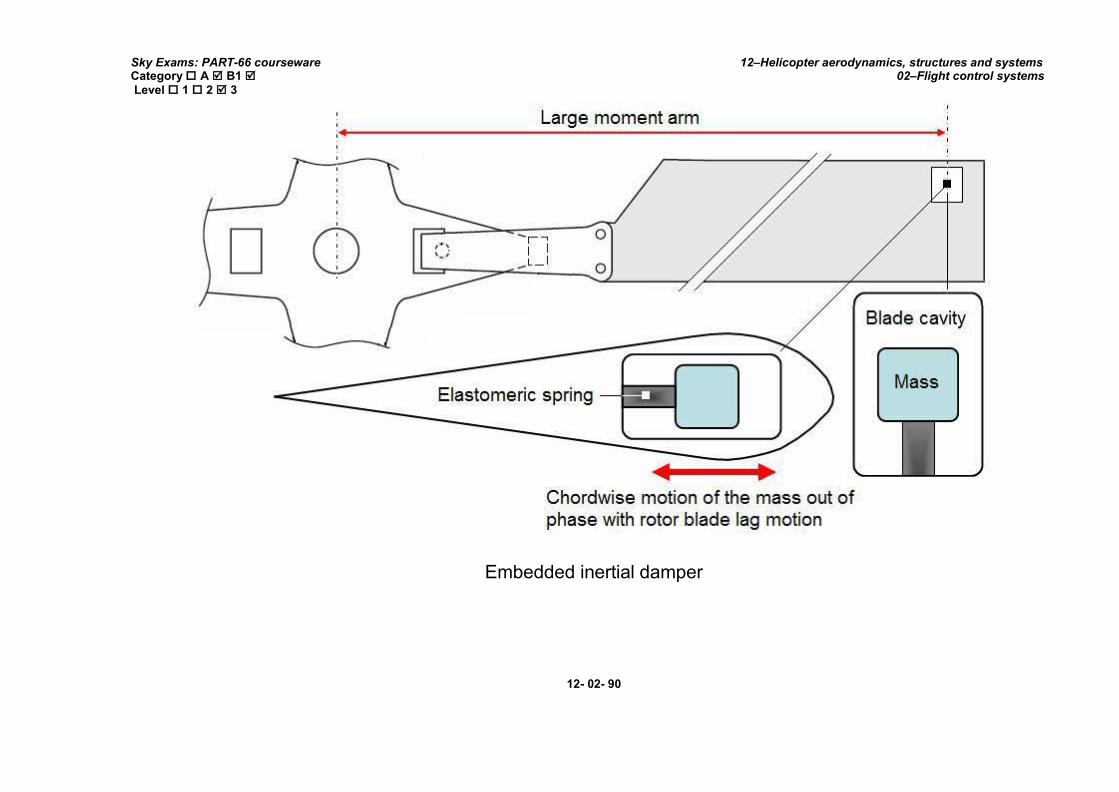
Sky Exams: PART-66 courseware Category A B1 Level 1 2 3
12–Helicopter aerodynamics, structures and systems 02–Flight control systems
Embedded inertial damper
12- 02- 90

Sky Exams: PART-66 courseware Category A B1 Level 1 2 3
12–Helicopter aerodynamics, structures and systems 02–Flight control systems
VIII. ROTOR BLADES: MAIN ANDTAIL ROTOR BLADE CONSTRUCTION AND ATTACHMENT
1. GENERAL:
A rotor is a whole made up of a hub (or rotor head) on which are fixed the blades. The rotor diameter choice depends on the use which will be made. Amongst other things, it is a function of the blades number, the horse-power available and speed of traverse. A rotor of low diameter decreases the weight and complexity, and increases the traverse speed. On the other hand, it requires a higher power available for the hovering. The reverse occurs for a rotor of large diameter which, moreover, offers a larger kinetic energy in autorotation. The number of blades depends primarily on the wing load (ratio of the mass to be raised on the rotor disc surface). A light helicopter will be able to have two or three blades, where as a large device has five or six of them.
2. BLADE DESIGNS:
The adopted designs of blades can be:
rectangular,
trapezoidal,
mixed.
The rotor blade is an aerofoil designed to rotate about a common axis to produce lift and provide directional control for a helicopter. It is often referred to as a rotary wing.
The design and construction of a rotor blade vary with the manufacturer, although they all strive to manufacture the most efficient and economical lifting device. The particular helicopter design places certain requirements on the main rotor blades, which influence their design and construction.
Most rotor blades are designed assymmetrical aerofoils to produce a stable aerodynamic pitching characteristic.
Aerodynamic stability is achieved when the centre of gravity, centre of pressure, and blade-feathering axis all act at the same point. The blade is more stable in flight because these forces continue to act at almost the same point as the blade changes pitch.
At present only one Army helicopter is equipped with an unsymmetrical aerofoil. This unsymmetrical aerofoil blade is capable of producing greater lift than asymmetrical aerofoil blade of similar dimensions.
Aerodynamic stability is achieved by building a 3° upward angle into the trailing edge section of the blade. This prevents excessive centre-of-pressure travel when the rotor blade angle of attack is changed.
12- 02- 91

Sky Exams: PART-66 courseware Category A B1 Level 1 2 3
12–Helicopter aerodynamics, structures and systems 02–Flight control systems
Typical rotor blades
12- 02- 92

Sky Exams: PART-66 courseware Category A B1 Level 1 2 3
12–Helicopter aerodynamics, structures and systems 02–Flight control systems
According to the figure above, we notice that the blade root end is notched because, in translation, it appears at this place a zone of unhooking and another one of reversed flow (comparable zones with those appearing in autorotation with translation).
A blade is a shaped surface intended to turn in an appreciably horizontal plane. Its characteristics are comparable with those of a plane wing; put aside the lengthening which is larger.
The lengthening of a blade is the ratio between its depth “e” on its length “RMax”.
A=
e
RMax
100%
12- 02- 93

Sky Exams: PART-66 courseware Category A B1 Level 1 2 3
12–Helicopter aerodynamics, structures and systems 02–Flight control systems
3. BLADE STRUCTURES AND MATERIALS:
3.1. Forces acting on blades:
The matters choice and the construction methods depend on the techniques of the moment but are especially based on the efforts which the blades must undergo.
Let us see in a diagrammatic way the resultant of the blade elementary efforts:
Efforts due to gravity (downwards inflection),
Traction efforts counter balanced by the efforts of opposed direction trail,
Centrifugal loads (wrenching),
Lift efforts (inflection upwards),
Inertial efforts due to the step variation,
Aerodynamic efforts of damping due to the vertical beats (alternating bending),
12- 02- 94

Sky Exams: PART-66 courseware Category A B1 Level 1 2 3
12–Helicopter aerodynamics, structures and systems 02–Flight control systems
Beats in the rotation plan due to the trail variations and the forces of “Coriolis” (alternating bending).
3.2. Types of blades:
Materials:
A variety of material is used in the construction of rotor blades; aluminum, steel, brass, and fiberglass are most common.
The first helicopter rotor blades were constructed out of laminated wood and fabric. One of the major drawbacks of using wood to construct the rotor blades is that wood absorbs moisture, which changes the mass of the rotor blade. Wooden rotor blades were used up until the 1960s, until they were replaced by steel and aluminium. Advantages of steel and aluminium rotor blades are that they're cheaper and easier to produce, and that they do not suffer from moisture absorption. However, disadvantages include a low strength to density ratio and a poor resistance to fatigue.
Today, composite materials are principally used for rotor blades.
Blades construction:
Blades are either full, or dig (blades out of box).
In the blades construction, it is necessary to avoid the processes resisting tiredness badly (notch effects, corrosion concentration, stress concentration). To this end, the assembly by bolts or rivets is avoided as much as possible; bonding is often preferred. A particularly delicate area of the blade is the fitting of fastener.
The assembly must carefully be studied for resumption as progressive as possible of the efforts (fittings in bevel, precise borings of the bolts holes, plastic film interposition between metal surfaces likely to present contact corrosion).
The bending stresses, alternate and permanent, are very high to approximately 20% of the ray. If the blade inking is done in the vicinity of this section, the precautions must be reinforced.
A typical metal blade has a hollow, extruded aluminum spar which forms the leading edge of the blade. Aluminum pockets bonded to the trailing edge of the spar assembly provide streamlining.
An aluminum tip cap is fastened with screws to the spar and tip pocket. A steel cuff bolted to the root end of the spar provides a means of attaching the blade to the rotor head.
A stainless steel abrasion strip is adhesive-bonded to the leading edge.
12- 02- 95

Sky Exams: PART-66 courseware Category A B1 Level 1 2 3
12–Helicopter aerodynamics, structures and systems 02–Flight control systems
3.3. Wood blades:
Wood the most used was: balsa, the spruce, the mahogany tree and the birch. The fibrous texture of wood confers on the blades a great flexibility which makes them less prone to the phenomena of tiredness than the metal blades (fittings of fastener put aside); moreover, the bonded assembly is extremely easy.
On the other hand, the variations in temperature and relative humidity cause deformations and frequent un-balancing, fabrication, were more over artisanal. These blades are not used anymore.
3.4. Metal blades:
The materials using the composition of these blades are mainly the alloys of aluminum and steels, often supplemented by the plastics.
The member is the centre-piece of the blade; it generally forms the leading edge and is often obtained by spinning (or an other process of the same kind) so as to have a fibrous texture authorizing the alternate constraints.
The trailing edge either is brought back to the spar, or integrated in the blade. It is sometimes reinforced by veins forming a box; it is often supplemented of filling light material (metal or plastic).
The blade skins are formed around and bonded to the spars, which in most cases form the leading edge of the blades. Metal blade skins are supported from the inside with aluminum honey comb, ribs, and some smaller blades which have no bracing or support inside themselves.
Metal tail rotor blades are usually of two constructional methods, the first uses a ‘D’ section extruded spar and ribs to form the blade shape, and the second a solid spar and honeycomb filling.
The illustration shows a tail rotor blade that uses the first of the two common constructional methods. It has an open, ‘D’ shaped extruded spar that runs from the blade tip, to the root, where it forms the attachment fitting. A small light alloy plate is bonded to the inside of the spar ‘lip’ to complete the D-shape and provide torsional strength and rigidity. Thin light alloy ribs are bonded to the rear face of the spar, providing shape and resisting compressive loads felt on the skin.
The light alloy skin is then bonded onto the whole structure, the use of bonding adhesives ensures an uninterrupted smooth skin that enhances aerodynamic efficiency and reduces drag. The leading edge is covered with a much tougher metal strip, such as stainless steel, nickel or tungsten, to provide an anti-erosion sheathing.
Like main rotor blades, the tail rotor blade must be balanced, in this example chordwise balance weights are fitted at the canted closing rib, close to the attachment fitting and spanwise weights are fitted at the tip.
These are then covered by a light alloy tip cap, which is normally riveted into place using a blind riveting technique.
12- 02- 96

Sky Exams: PART-66 courseware Category A B1 Level 1 2 3
12–Helicopter aerodynamics, structures and systems 02–Flight control systems
Metal blade principle
12- 02- 97
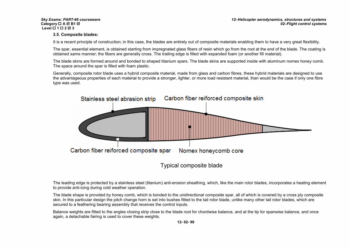
Sky Exams: PART-66 courseware Category A B1 Level 1 2 3
12–Helicopter aerodynamics, structures and systems 02–Flight control systems
3.5. Composite blades:
It is a recent principle of construction; in this case, the blades are entirely out of composite materials enabling them to have a very great flexibility.
The spar, essential element, is obtained starting from impregnated glass fibers of resin which go from the root at the end of the blade. The coating is obtained same manner; the fibers are generally cross. The trailing edge is filled with expanded foam (or another fill material).
The blade skins are formed around and bonded to shaped titanium spars. The blade skins are supported inside with aluminum nomex honey comb. The space around the spar is filled with foam plastic.
Generally, composite rotor blade uses a hybrid composite material, made from glass and carbon fibres, these hybrid materials are designed to use the advantageous properties of each material to provide a stronger, lighter, or more load resistant material, than would be the case if only one fibre type was used.
Typical composite blade
The leading edge is protected by a stainless steel (titanium) anti-erosion sheathing, which, like the main rotor blades, incorporates a heating element to provide anti-icing during cold weather operation.
The blade shape is provided by honey comb, which is bonded to the unidirectional composite spar, all of which is covered by a cross ply composite skin. In this particular design the pitch change horn is set into bushes fitted to the tail rotor blade, unlike many other tail rotor blades, which are secured to a feathering bearing assembly that receives the control inputs.
Balance weights are fitted to the angles closing strip close to the blade root for chordwise balance, and at the tip for spanwise balance, and once again, a detachable fairing is used to cover these weights.
12- 02- 98

Sky Exams: PART-66 courseware Category A B1 Level 1 2 3
12–Helicopter aerodynamics, structures and systems 02–Flight control systems
3.6. NACA design aerooils:
The NACA aerofoils are aerofoil shapes for aircraft wings developed by the National Advisory Committee for Aeronautics (NACA). The shape of the NACA aerofoils is described using a series of digits following the word "NACA".
The parameters in the numerical code can be entered into equations to precisely generate the cross-section of the aerofoil and calculate its
properties. The NACA four-digit wing sections define the profile by:
First digit describing maximum camber as percents of the chord.
Second digit describing the distance of maximum camber from the airfoil leading edge in tens of percents of the chord.
Last two digits describing maximum thickness of the aerofoil as percents of the chord.
Four-digit series airfoils by default have maximum thickness at 30% of the chord (0.3chords) from the leading edge.
Example1: NACA 0015 aerofoil:
The NACA 0015 aerofoil is symmetrical, the 00 indicating that it has no camber. The15 indicates that the aerofoil has a 15% thickness to chord length ratio: it is 15% as thick as it is long.
12- 02- 99

Sky Exams: PART-66 courseware Category A B1 Level 1 2 3
12–Helicopter aerodynamics, structures and systems 02–Flight control systems
Example1: NACA2412 aerofoil:
Symmetrical NACA0015 aerofoil
The NACA2412 aerofoil is non-symmetrical; it has a maximum camber of 2% located 40% (0.4chords) from the leading edge with a maximum thickness of12% of the chord.
Non-symmetrical NACA 2412aerofoil
3.7. ONERA design aerofoils:
The ONERA aerofoils are aerofoil shapes for aircraft wings developed by the French “Office National d ’Etudeset Recherche
Aéronautique”. The shape of the ONERA aerofoils is described using a series of digits following the letters "OA".
12- 02- 100
Related Documents