D1 Parker Hannifin Corporation Pneumatic Division Richland, Michigan www.parker.com/pneumatics D Moduflex Valve System Instant Control For All Pneumatic Actuators Modular Valve Islands or Stand-Alone Valves Section D www.parker.com/pneu/moduflex Model Selection & Assembly ............................... D2-D3 Basic Valve Functions ......................................... D4-D5 S Series ............................................................. D6-D11 T Series ........................................................... D12-D17 V Series ........................................................... D18-D26 Technical Information, Device Bus Modules.... D27-D33 Accessories ..................................................... D34-D37 P Series ........................................................... D38-D41 Intermediate Supply Module Model Number Index .D42 Internal / External Pilot Technical Information ......... D43 Moduflex Island Assembly Model Number Index .... D44 V Series Assemblies & Components ...................... D45 Maintenance Procedure .......................................... D46 Maintenance Components ...................................... D47 Specifications .......................................................... D48 Dimensions ...................................................... D49-D55 Valve Island Configurator CD-ROM................. D56-D57 BOLD ITEMS ARE MOST POPULAR.

Welcome message from author
This document is posted to help you gain knowledge. Please leave a comment to let me know what you think about it! Share it to your friends and learn new things together.
Transcript

D1 Parker Hannifin CorporationPneumatic DivisionRichland, Michiganwww.parker.com/pneumatics
D
Moduflex Valve SystemInstant Control For All Pneumatic Actuators
Modular Valve Islands orStand-Alone Valves
Section Dwww.parker.com/pneu/moduflex
Model Selection & Assembly ...............................D2-D3
Basic Valve Functions .........................................D4-D5
S Series .............................................................D6-D11
T Series ...........................................................D12-D17
V Series ...........................................................D18-D26
Technical Information, Device Bus Modules....D27-D33
Accessories .....................................................D34-D37
P Series ...........................................................D38-D41
Intermediate Supply Module Model Number Index .D42
Internal / External Pilot Technical Information .........D43
Moduflex Island Assembly Model Number Index ....D44
V Series Assemblies & Components ......................D45
Maintenance Procedure ..........................................D46
Maintenance Components ......................................D47
Specifications ..........................................................D48
Dimensions ......................................................D49-D55
Valve Island Configurator CD-ROM.................D56-D57
BOLD ITEMS ARE MOST POPULAR.

Parker Hannifin CorporationPneumatic DivisionRichland, Michiganwww.parker.com/pneumatics
D2
D
Moduflex Valve System“S”, “T”, “V” & “P” Series
Catalog 0600P-10/USA
Module Selection & Assembly
Module Series Selection and Assembly ProceduresModuflex system provides a complete choice of either stand-alone valves, short-build valve islands, or large valve island configurations. Electrical control connections may be individual or island integrated. Peripheral modules add complementary functions — flow control, pressure regulation, P.O. check valves and vacuum generators can be added directly to the valve or used as a stand alone product.
“T” Series Island Modules
“T” Series Valve Island Modules with Individual ConnectorsFor small groups of cylinders requiring short localized valve islands, it is convenient to use individual electrical connector islands.
“S” Series Stand Alone ValvesFor isolated cylinders on a machine, it is preferable to locate the valve close by. Therefore a stand-alone module is ideal. Response time and air consumption are then reduced to a minimum. Peripheral modules can be installed directly into the valve.
Moduflex gives machine builders maximum flexibility to assemble each automation system step by step using basic modules.
Valve islands can be easily assembled using the following procedure.
1. Assemble the required valve island with the basic modules.
2. Mount the valve island on the machine together with any stand-alone valves and peripheral modules.
3. Select and install the required clip-on pneumatic and electrical connectors.
TORX Wrench*
Flow Control
“S” Series Size 1 Single Solenoid
Straight or Elbow
Pneumatic Connectors
UnionPneumatic Connectors
Dual P.O. Check Valve
Straight or Elbow
Pneumatic Connectors
Union“S” Series Size 1 Single Air Pilot
“T” Series modules are easily assembled to form a complete manifold. All electrical connectors are individual and pneumatic connectors are of the push-in tube type. Modules with different functions and flow passages may be combined in the same island manifold, giving total flexibility to adapt to all machine requirements.
* Maximum torque rating 10.6 in. lbs. (1.2 Nm).

Parker Hannifin CorporationPneumatic DivisionRichland, Michiganwww.parker.com/pneumatics
D3
D
“V” Series Valve Island Modules with Integrated ConnectionsWhen the number of valves is larger, modular islands are easily assembled using the integrated electrical connection series. These islands are then connected to the control PLC, with a multi-connector cable or with a field bus connection.
“V” Series with 20-Pin Connector
“V” Series with Field Bus Connection
* Maximum torque rating 10.6 in. lbs. (1.2 Nm).
“P” Series Peripheral ModulesPeripheral Modules are available and can be mounted directly to valves or used as a stand alone product. These modules answer the complementary needs of the cylinders, flow controls, pressure regulation or positioning.
Pressure Regulator
Dual P.O. Check Valve
Straight or Elbow Pneumatic Connectors
TORX Wrench*
Moduflex Valve System“S”, “T”, “V” & “P” Series
Catalog 0600P-10/USA
Module Selection & Assembly
Flow Control
Vacuum Generator
“V” Series modules are easily assembled to form a complete manifold. All pneumatic connectors are of the push-in tube type. When the valve island has been installed, it is a simple operation to separate the field bus module from the valve island using the quick release lever. Modules with different functions and flow passages may be combined in the same island manifold, giving total flexibility to adapt to all machine requirements.
PressureSensor
Parker Hannifin CorporationPneumatic DivisionRichland, Michiganwww.parker.com/pneumatics
D4
D
Catalog 0600P-10/USA
Basic Valve FunctionsModuflex Valve System4/2 Single & Dual Valves
Moduflex Valve Islands offer the greatest flexibility for your design requirements.
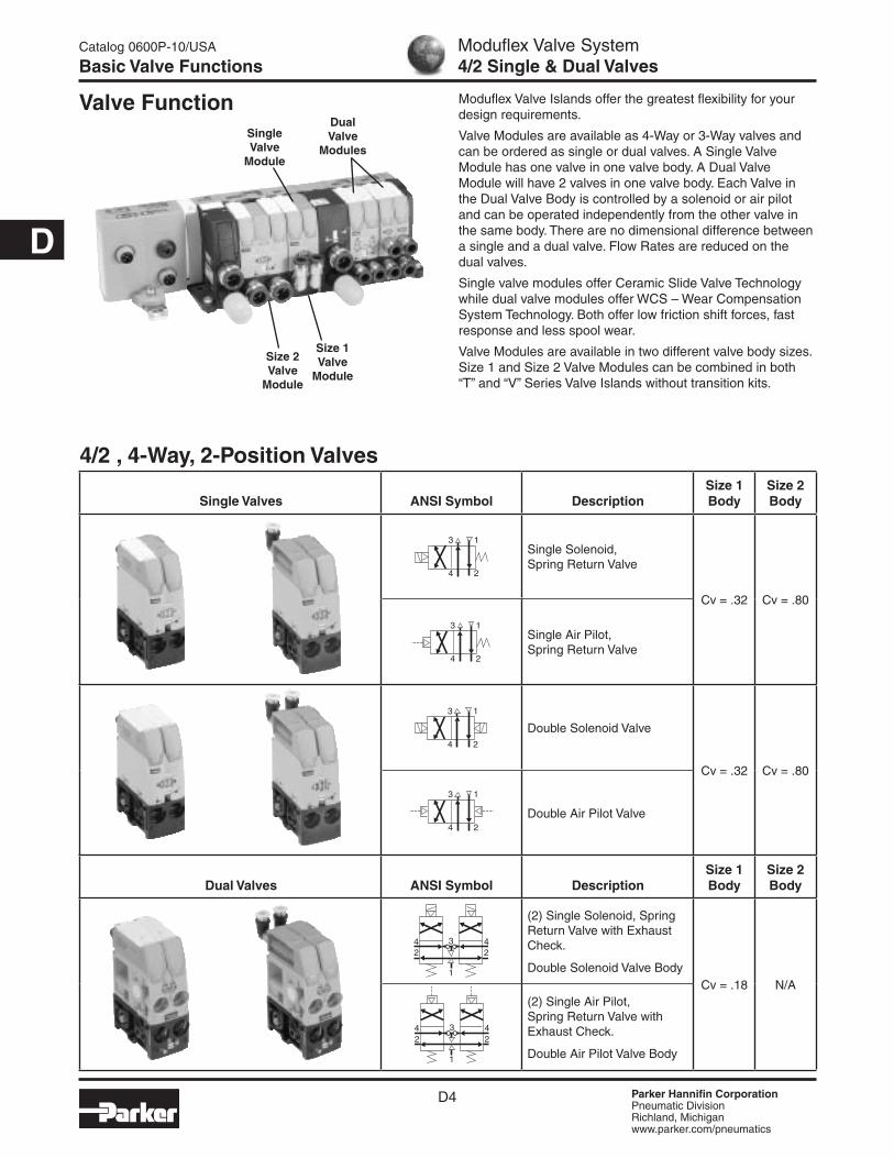
Valve Modules are available as 4-Way or 3-Way valves and can be ordered as single or dual valves. A Single Valve Module has one valve in one valve body. A Dual Valve Module will have 2 valves in one valve body. Each Valve in the Dual Valve Body is controlled by a solenoid or air pilot and can be operated independently from the other valve in the same body. There are no dimensional difference between a single and a dual valve. Flow Rates are reduced on the dual valves.
Single valve modules offer Ceramic Slide Valve Technology while dual valve modules offer WCS – Wear Compensation System Technology. Both offer low friction shift forces, fast response and less spool wear.
Valve Modules are available in two different valve body sizes. Size 1 and Size 2 Valve Modules can be combined in both “T” and “V” Series Valve Islands without transition kits.
4/2 , 4-Way, 2-Position Valves
Single Valves ANSI Symbol DescriptionSize 1 Body
Size 2 Body
Single Solenoid, Spring Return Valve
Cv = .32 Cv = .80
Single Air Pilot, Spring Return Valve
Double Solenoid Valve
Cv = .32 Cv = .80
Double Air Pilot Valve
Dual Valves ANSI Symbol DescriptionSize 1 Body
Size 2 Body
(2) Single Solenoid, Spring Return Valve with Exhaust Check.
Double Solenoid Valve BodyCv = .18 N/A
(2) Single Air Pilot, Spring Return Valve with Exhaust Check.
Double Air Pilot Valve Body
Valve Function
3 1
4 2
3 1
4 2
1
2234 4
1
2234 4
3 1
4 2
Size 1 Valve
Module
Size 2 Valve
Module
Dual Valve
ModulesSingle Valve
Module
3 1
4 2
Parker Hannifin CorporationPneumatic DivisionRichland, Michiganwww.parker.com/pneumatics
D5
D
3/2 , 3-Way, 2-Position Valves
Single Valves ANSI Symbol DescriptionSize 1 Body
Size 2 Body
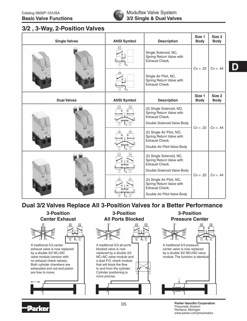
Single Solenoid, NC, Spring Return Valve with Exhaust Check.
Cv = .22 Cv = .44
Single Air Pilot, NC, Spring Return Valve with Exhaust Check.
Dual Valves ANSI Symbol DescriptionSize 1 Body
Size 2 Body
(2) Single Solenoid, NO, Spring Return Valve with Exhaust Check.
Double Solenoid Valve BodyCv = .22 Cv = .44
(2) Single Air Pilot, NO, Spring Return Valve with Exhaust Check.
Double Air Pilot Valve Body
(2) Single Solenoid, NC, Spring Return Valve with Exhaust Check.
Double Solenoid Valve BodyCv = .22 Cv = .44
(2) Single Air Pilot, NC, Spring Return Valve with Exhaust Check.
Double Air Pilot Valve Body
Catalog 0600P-10/USA
Basic Valve FunctionsModuflex Valve System3/2 Single & Dual Valves
3
1
4
3
1
4
3
1
4 2
3
1
4 2
3
1
4 2
3
1
4 2
3
1
1
4 2
4 2
1
4 2
1
4 23
4 2
1
4 2
3
1
4 2
3-Position All Ports Blocked
A traditional 5/3 all ports blocked valve is now replaced by a double 3/2 NC+NC valve module and a dual P.O. check module that will block the flow to and from the cylinder. Cylinder positioning is more precise.
3-Position Center Exhaust
A traditional 5/3 center exhaust valve is now replaced by a double 3/2 NC+NC valve module (version with no exhaust check valves). Both cylinder chambers are exhausted and rod and piston are free to move.
Dual 3/2 Valves Replace All 3-Position Valves for a Better Performance3-Position
Pressure Center
A traditional 5/3 pressure center valve is now replaced by a double 3/2 NO+NO valve module. The function is identical.

Parker Hannifin CorporationPneumatic DivisionRichland, Michiganwww.parker.com/pneumatics
D6
D
Moduflex Valve System“S” Series Basic Modules Size 1
Catalog 0600P-10/USA
Ordering Guide
Size 1 Electro-Pneumatic Stand Alone Valve Modules, 24VDC
Single Solenoid Double Solenoid
“S” Series Basic Modules Size 1 (Without Pneumatic Connectors)
Size 1 Air Pilot Stand Alone Valve Modules
Single Air Pilot Double Air Pilot
4-Way / 2-Position / Single Valve
Solenoid Weight Part Number
Single Solenoid (Monostable)
2.54 oz P2M1S4ES2C
Double Solenoid (Bistable)
3.07 oz P2M1S4EE2C
3-Way / 2-Position / Dual Valve
Solenoid Weight Part Number
Double Solenoid NC + NC with Exhaust Check
3.00 oz P2M1SDEE2C
Double Solenoid NO + NO with Exhaust Check
3.00 oz P2M1SCEE2C
Double Solenoid NC + NO with Exhaust Check
3.00 oz P2M1SEEE2C
Single Solenoid NC with Exhaust Check
2.82 oz P2M1S3ES2C
Center Exhaust = dual 3/2 NC + NC without Exhaust Check
3.00 oz P2M1SGEE2C3
1
4 2
3
1
4 2
3
1
4 2
3
1
4 2
3
1
4
3 1
4 2
3 1
4 2
4-Way / 2-Position / Single Valve
Solenoid Weight Part Number
Single Air Pilot (Monostable)
2.54 oz P2M1S4PS
Double Air Pilot (Bistable)
3.07 oz P2M1S4PP
3-Way / 2-Position / Dual Valve
Solenoid Weight Part Number
Double Air Pilot NC + NC with Exhaust Check
2.82 oz P2M1SDPP
Double Air Pilot NO + NO with Exhaust Check
2.82 oz P2M1SCPP
Single Air Pilot NC
2.68 oz P2M1S3PS
3
1
4 2
3
1
4 2
3
1
4
3 1
4 2
3 1
4 2
Note: Bold Options Standard
Note: Includes 5/32" (4mm) Air Pilot Connectors.

Parker Hannifin CorporationPneumatic DivisionRichland, Michiganwww.parker.com/pneumatics
D7
D
Note: 85 Durometer minimum for pneumatic connectors.
Pneumatic Connectors for Size 1 Modules
With LED Voltage Surge Protectionand Flying Lead CableIP67 Protected
Weight (oz)
Order Code
2 m Cable 2.19 P8LS08L226C
5 m Cable 5.47 P8LS08L526C
9 m Cable 9.88 P8LS08L926C
M8 Female Individual Connectors with Flying Lead Cable (For Solenoid Pilots)
MMDVA1PMDYY1
FMD04-1 CMD04-1 FMD07-1B CMD07-1B
HMDXX1
Moduflex Valve System“S” Series Basic Modules Size 1
Catalog 0600P-10/USA
Ordering Guide
Elbow Version Straight Version
Weight (oz)
Order Code
Weight(oz)
Order Code
Tube Push-in
Connector
5/32" = 4mm OD
0.18 CMD04-1 0.07 FMD04-1
6mm OD 0.18 CMD06-1 0.11 FMD06-1
1/4" OD 0.18 CMD07-1B 0.11 FMD07-1B
Muffler for Exhaust Port
— — — 0.11 MMDVA1
Plug — — — 0.18 PMDYY1
Double Male Union
(For Peripheral Valve Modules)
— — — 0.21 HMDXX1
Parker Hannifin CorporationPneumatic DivisionRichland, Michiganwww.parker.com/pneumatics
D8
D
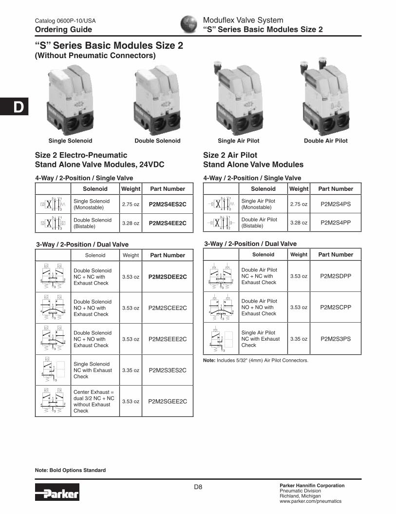
“S” Series Basic Modules Size 2 (Without Pneumatic Connectors)
Size 2 Electro-Pneumatic Stand Alone Valve Modules, 24VDC
Moduflex Valve System“S” Series Basic Modules Size 2
Catalog 0600P-10/USA
Ordering Guide
Single Solenoid Double Solenoid
Size 2 Air Pilot Stand Alone Valve Modules
Single Air Pilot Double Air Pilot
4-Way / 2-Position / Single Valve
Solenoid Weight Part Number
Single Solenoid (Monostable)
2.75 oz P2M2S4ES2C
Double Solenoid (Bistable)
3.28 oz P2M2S4EE2C
3-Way / 2-Position / Dual Valve
Solenoid Weight Part Number
Double Solenoid NC + NC with Exhaust Check
3.53 oz P2M2SDEE2C
Double Solenoid NO + NO with Exhaust Check
3.53 oz P2M2SCEE2C
Double Solenoid NC + NO with Exhaust Check
3.53 oz P2M2SEEE2C
Single Solenoid NC with Exhaust Check
3.35 oz P2M2S3ES2C
Center Exhaust = dual 3/2 NC + NC without Exhaust Check
3.53 oz P2M2SGEE2C
3
1
4 2
3
1
4 2
3
1
4 2
3
1
4 2
3
1
4
3 1
4 2
3 1
4 2
4-Way / 2-Position / Single Valve
Solenoid Weight Part Number
Single Air Pilot (Monostable)
2.75 oz P2M2S4PS
Double Air Pilot (Bistable)
3.28 oz P2M2S4PP
3-Way / 2-Position / Dual Valve
Solenoid Weight Part Number
Double Air Pilot NC + NC with Exhaust Check
3.53 oz P2M2SDPP
Double Air Pilot NO + NO with Exhaust Check
3.53 oz P2M2SCPP
Single Air Pilot NC with Exhaust Check
3.35 oz P2M2S3PS
3
1
4 2
3
1
4 2
3
1
4
3 1
4 2
3 1
4 2
Note: Bold Options Standard
Note: Includes 5/32" (4mm) Air Pilot Connectors.

Parker Hannifin CorporationPneumatic DivisionRichland, Michiganwww.parker.com/pneumatics
D9
DWith LED Voltage Surge Protectionand Flying Lead CableIP67 Protected
Weight (oz)
Order Code
2 m Cable 2.19 P8LS08L226C
5 m Cable 5.47 P8LS08L526C
9 m Cable 9.88 P8LS08L926C
M8 Female Individual Connectors with Flying Lead Cable (For Solenoid Pilots)
Elbow Version Straight Version
Weight (oz)
Order Code
Weight(oz)
Order Code
Tube Push-in
Connector
6mm OD 0.18 CMD06-2 0.11 FMD06-2
1/4" OD 0.18 CMD07-2B 0.11 FMD07-2B
8mm OD 0.21 CMD08-2 0.14 FMD08-2
3/8" OD 0.21 CMD09-2B 0.14 FMD09-2B
10mm OD 0.25 CMD10-2 0.18 FMD10-2
12mm OD 0.28 CMD12-2 0.21 FMD12-2
1/2" OD — — 0.21 FMD13-2B
Muffler for Exhaust Port
— — — 0.11 MMDVA2
Plug — — — 0.18 PMDYY2
Double Male Union
(For Peripheral Valve Modules)
— — — 0.28 HMDXX2
Note: 85 Durometer minimum for pneumatic connectors.
MMDVA2
CMD09-2B
PMDYY2
FMD09-2BHMDXX2
Pneumatic Connectors for Size 2 Modules
Moduflex Valve System“S” Series Basic Modules Size 2
Catalog 0600P-10/USA
Ordering Guide(Revised 07-23-07)

Parker Hannifin CorporationPneumatic DivisionRichland, Michiganwww.parker.com/pneumatics
D10
D
Moduflex Valve System“S” Series Complete Modules
Catalog 0600P-10/USA
Model Number Index
1. Push - Release
3. Remove Lock Capability
4. Manual Override is Totally Isolated
2. Push - Twist - Lock
LockingStop
IsolationFork
1. Push - Release
3. Remove Lock Capability
4. Manual Override is Totally Isolated
2. Push - Twist - Lock
LockingStop
IsolationFork
BOLD OPTIONS ARE MOST POPULAR.
Basic SeriesModuflex P2M
SizeSize 1 1Size 2 2
Valve Type / Function3-Way / 2-Position
Single Solenoid, NC Spring Return 3ESSingle Air Pilot, NC Spring Return 3PS
4-Way / 2-PositionSingle Solenoid, Spring Return 4ESSingle Air Pilot, Spring Return 4PSDouble Solenoid 4EEDouble Air Pilot 4PP
Dual 3-Way, 2-Position, Spring ReturnSolenoid, NC / NC + PO Check (4/3 APB) BEE*Air Pilot, NC / NC + PO Check (4/3 APB) BPP*Solenoid, NO / NO (4/3 Pressure Ctr.) CEEAir Pilot NO / NO (4/3 Pressure Ctr.) CPPSolenoid, NC / NC with Exhaust Check DEEAir Pilot, NC / NC with Exhaust Check DPPSolenoid, NO / NC with Exhaust Check EEESolenoid, NC / NC without Check (4/3 Exh. Ctr.) GEE
* Valve includes peripheral P. O. Check Valve and union fittings. LED / Cable00 No Cable, No LED, No Surge SuppressionV2 2 Meter Cable with LED and Surge SuppressionV5 5 Meter Cable with LED and Surge SuppressionV9 9 Meter Cable with LED and Surge Suppression
P2M 1 S 4ES 2C 00 A F4
Valve SeriesStand Alone S
Fitting ConfigurationA* Straight FittingsB* Elbow FittingsC*† Straight Fitting & MufflerD*† Elbow Fitting & Muffler* Ports 1 & 3 fittings sizes are same as Ports 2
& 4 (See example at left.)† Fitting in Port 1, Muffler in Port 3.
Ports (All Ports)C0* 10mm Elbow FittingC2* 12mm Elbow FittingC4 5/32" (4mm) Elbow FittingC6 6mm Elbow FittingC7 1/4" Elbow FittingC8* 8mm Elbow FittingC9* 3/8" Elbow FittingF0* 10mm Elbow FittingF2* 12mm Elbow FittingF3* 1/2" Straight FittingF4 5/32" (4mm) Straight FittingF6 6mm Straight FittingF7 1/4" Straight FittingF8* 8mm Straight FittingF9* 3/8" Straight Fitting* Only Available with Size 2 Valves.
Operator Voltage24VDC 2CRemote Pilot - 5/32" (4mm) Tube 00
“S” Series Stand-alone Valve Modules Model Number Index Complete Modules (Complete with Pneumatic and Electrical Connectors)
EXAMPLE for Fitting Configuration:
Size 1
CF7 Ports 1 & 3 1/4" Straight Fitting & Muffler Ports 2 & 4 1/4" Straight Fittings
Size 2
AC0 Ports 1 & 3 10mm Elbow Fittings Ports 2 & 4 10mm Elbow Fittings
With Only One Universal Solenoid Pilot for all Configurations24VDC is now a global standard for all machines.
The Moduflex 24VDC unique solenoid pilot is supplied with the multi-function manual override that can be adapted to all requirements, as explained by the drawings.
Multi-Function Adaptable Manual Override

Parker Hannifin CorporationPneumatic DivisionRichland, Michiganwww.parker.com/pneumatics
D11
D
Moduflex Valve System“S” Series Assemblies & Components
Catalog 0600P-10/USA
Ordering Information
How to Order Complete Valve AssemblyLine Item Quantity Part Number Description
1 1 P2M1S4ES2CV2CF7Size 1, Stand Alone Valve Module, 4 Way, Single Solenoid, 2m Cable with LED / Surge Suppression, Exhaust Muffler with 1/4” OD Straight Port Fittings
Notes: 1. Cables supplied loose with valve.2. For LED and Surge Suppressor, cable must be supplied with valve.
“S” Series Single Solenoid
Example:Size 1, 4-Way Single Solenoid valve with 1/4" Straight Connectors in Ports 1, 2 and 4. Exhaust Muffler in Port 3. Valve to include 2m cable with LED and surge suppression.
How to Order ComponentsLine Item Quantity Part Number Description
1 1 P2M1S4ES2C Size 1, Stand Alone Valve Module, Single Solenoid, 4 Way
2 1 P8LS08L226C 2m Cable with LED / Surge Suppression
3 3 FMD07-1B Size 1, 1/4” OD Tube Push In Connector
4 1 MMDVA1 Size 1, Muffler for Exhaust Port

Parker Hannifin CorporationPneumatic DivisionRichland, Michiganwww.parker.com/pneumatics
D12
D
Moduflex Valve System“T” Series Basic Modules Size 1
Catalog 0600P-10/USA
Ordering Guide
“T” Series Basic Modules Size 1 (Without Pneumatic Connectors)
Size 1 Electro-Pneumatic Island Valve Modules, 24VDC4-Way / 2-Position / Single Valve
Solenoid Weight Part Number
Single Solenoid (Monostable)
2.40 oz P2M1T4ES2C
Double Solenoid (Bistable)
2.72 oz P2M1T4EE2C
4-Way / 2-Position / Dual Valve
Solenoid Weight Part Number
Solenoid Spring with Exhaust Check
2.72 oz P2M1TJEE2C
3-Way / 2-Position / Dual Valve
Solenoid Weight Part Number
Double Solenoid NC + NC with Exhaust Check
2.82 oz P2M1TDEE2C
Double Solenoid NO + NO with Exhaust Check
2.82 oz P2M1TCEE2C
Double Solenoid NC + NO with Exhaust Check
2.82 oz P2M1TEEE2C
Single Solenoid NC with Exhaust Check
2.68 oz P2M1T3ES2C
Center Exhaust = dual 3/2 NC + NC without Exhaust Check
2.84 oz P2M1TGEE2C
3
1
4 2
3
1
4 2
3
1
4 2
3
1
4 2
3
1
4
3 1
4 2
3 1
4 2
Single Solenoid Double Solenoid
1
2234 4
Size 1 Air Pilot Island Valve Modules
Single Air Pilot Double Air Pilot
4-Way / 2-Position / Single Valve
Solenoid Weight Part Number
Single Air Pilot (Monostable)
2.40 oz P2M1T4PS
Double Air Pilot (Bistable)
2.72 oz P2M1T4PP
4-Way / 2-Position / Dual Valve
Solenoid Weight Part Number
Air Pilot Spring with Exhaust Check
2.72 oz P2M1TJPP
3-Way / 2-Position / Dual Valve
Solenoid Weight Part Number
Double Air Pilot NC + NC with Exhaust Check
2.82 oz P2M1TDPP
Double Air Pilot NO + NO with Exhaust Check
2.82 oz P2M1TCPP
Single Air Pilot NC with Exhaust Check
2.68 oz P2M1T3PS
3
1
4 2
3
1
4 2
3
1
4
3 1
4 2
3 1
4 2
1
2234 4
Note: Bold Options Standard
Note: Includes 5/32" (4mm) Air Pilot Connectors.

Parker Hannifin CorporationPneumatic DivisionRichland, Michiganwww.parker.com/pneumatics
D13
D
Moduflex Valve System“T” Series Basic Modules Size 1
Catalog 0600P-10/USA
Ordering Guide
Elbow Version Straight Version
Weight (oz)
Order Code
Weight(oz)
Order Code
Tube Push-in
Connector
5/32" = 4mm OD
0.18 CMD04-1 0.07 FMD04-1
6mm OD 0.18 CMD06-1 0.11 FMD06-1
1/4" OD 0.18 CMD07-1B 0.11 FMD07-1B
Muffler for Exhaust Port
— — — 0.11 MMDVA1
Plug — — — 0.18 PMDYY1
Double Male Union
(For Peripheral Valve Modules)
— — — 0.21 HMDXX1
Note: 85 Durometer minimum for pneumatic connectors.
Island ModulesModule Weight (oz) Order Code
Pneumatic Head and Tail Set 2.26 P2M2HXT01*
Pneumatic Head and Tail Set with TORX Screwdriver
2.50 P2M2HXT0T*
TORX Screwdriver Only .24 P2M1K0TASD
Intermediate Supply Module (With a set of 4
Configuration Plates)1.48 P2M2BXT0A*
MMDVA1PMDYY1
P2M2HXT01
CMD04-1 FMD07-1B CMD07-1B
HMDXX1With LED Voltage Surge Protectionand Flying Lead CableIP67 Protected
Weight (oz)
Order Code
2 m Cable 2.19 P8LS08L226C
5 m Cable 5.47 P8LS08L526C
9 m Cable 9.88 P8LS08L926C
M8 Female Individual Connectors with Flying Lead Cable (For Solenoid Pilots)
P2M2BXT0A
* Use Fittings for Size 2 Modules Only.
Pneumatic Connectors for Size 1 Modules
P2M1K0TASD
(Revised 07-23-07)

Parker Hannifin CorporationPneumatic DivisionRichland, Michiganwww.parker.com/pneumatics
D14
D
Size 2 Electro-Pneumatic Island Valve Modules, 24VDC
Moduflex Valve System“T” Series Basic Modules Size 2
Catalog 0600P-10/USA
Ordering Guide
Single Solenoid Double Solenoid
Size 2 Air Pilot Island Valve Modules
Single Air Pilot Double Air Pilot
4-Way / 2-Position / Single Valve
Solenoid Weight Part Number
Single Solenoid (Monostable)
2.61 oz P2M2T4ES2C
Double Solenoid (Bistable)
2.93 oz P2M2T4EE2C
3-Way / 2-Position / Dual Valve
Solenoid Weight Part Number
Double Solenoid NC + NC with Exhaust Check
3.32 oz P2M2TDEE2C
Double Solenoid NO + NO with Exhaust Check
3.32 oz P2M2TCEE2C
Double Solenoid NC + NO with Exhaust Check
3.32 oz P2M2TEEE2C
Single Solenoid NC with Exhaust Check
3.17 oz P2M2T3ES2C
Center Exhaust = dual 3/2 NC + NC without Exhaust Check
3.32 oz P2M2TGEE2C
3
1
4 2
3
1
4 2
3
1
4 2
3
1
4 2
3
1
4
3 1
4 2
3 1
4 2
4-Way / 2-Position / Single Valve
Solenoid Weight Part Number
Single Air Pilot (Monostable)
2.61 oz P2M2T4PS
Double Air Pilot (Bistable)
2.93 oz P2M2T4PP
3-Way / 2-Position / Dual Valve
Solenoid Weight Part Number
Double Air Pilot NC + NC with Exhaust Check
3.32 oz P2M2TDPP
Double Air Pilot NO + NO with Exhaust Check
3.32 oz P2M2TCPP
Single Air Pilot NC with Exhaust Check
2.61 oz P2M2T3PS
3
1
4 2
3
1
4 2
3
1
4
3 1
4 2
3 1
4 2
Note: Bold Options Standard
“T” Series Basic Modules Size 2 (Without Pneumatic Connectors)
Note: Includes 5/32" (4mm) Air Pilot Connectors.

Parker Hannifin CorporationPneumatic DivisionRichland, Michiganwww.parker.com/pneumatics
D15
D
Note: 85 Durometer minimum for pneumatic connectors.
MMDVA2PMDYY2
HMDXX2
With LED Voltage Surge Protectionand Flying Lead CableIP67 Protected
Weight (oz)
Order Code
2 m Cable 2.19 P8LS08L226C
5 m Cable 5.47 P8LS08L526C
9 m Cable 9.88 P8LS08L926C
M8 Female Individual Connectors with Flying Lead Cable (For Solenoid Pilots)
P2M2HXT01
P2M2BXT0A
Pneumatic Connectors for Size 2 Modules
Moduflex Valve System“T” Series Basic Modules Size 2
Catalog 0600P-10/USA
Ordering Guide
Elbow Version Straight Version
Weight (oz)
Order Code
Weight(oz)
Order Code
Tube Push-in
Connector
6mm OD 0.18 CMD06-2 0.11 FMD06-2
1/4" OD 0.18 CMD07-2B 0.11 FMD07-2B
8mm OD 0.21 CMD08-2 0.14 FMD08-2
3/8" OD 0.21 CMD09-2B 0.14 FMD09-2B
10mm OD 0.25 CMD10-2 0.18 FMD10-2
12mm OD 0.28 CMD12-2 0.21 FMD12-2
1/2" OD — — 0.21 FMD13-2B
Muffler for Exhaust Port
— — — 0.11 MMDVA2
Plug — — — 0.18 PMDYY2
Double Male Union
(For Peripheral Valve Modules)
— — — 0.28 HMDXX2
P2M1K0TASD
Island ModulesModule Weight (oz) Order Code
Pneumatic Head and Tail Set 2.26 P2M2HXT01*
Pneumatic Head and Tail Set with TORX Screwdriver
2.50 P2M2HXT0T*
TORX Screwdriver Only .24 P2M1K0TASD
Intermediate Supply Module (With a set of 4
Configuration Plates)1.48 P2M2BXT0A*
* Use Fittings for Size 2 Modules Only.
CMD09-2BFMD09-2B
(Revised 07-23-07)
Parker Hannifin CorporationPneumatic DivisionRichland, Michiganwww.parker.com/pneumatics
D16
D
Moduflex Valve System“T” Series Complete Modules
Catalog 0600P-10/USA
Model Number Index
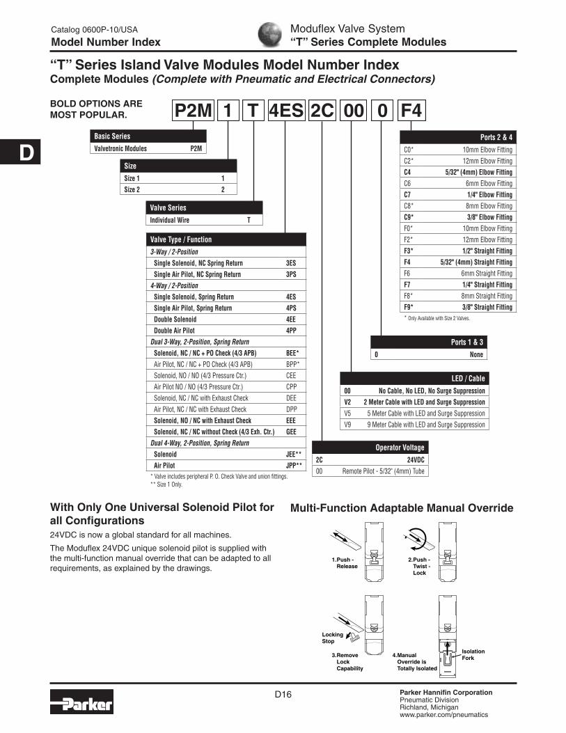
“T” Series Island Valve Modules Model Number Index Complete Modules (Complete with Pneumatic and Electrical Connectors)
With Only One Universal Solenoid Pilot for all Configurations24VDC is now a global standard for all machines.
The Moduflex 24VDC unique solenoid pilot is supplied with the multi-function manual override that can be adapted to all requirements, as explained by the drawings.
Multi-Function Adaptable Manual Override
1. Push - Release
3. Remove Lock Capability
4. Manual Override is Totally Isolated
2. Push - Twist - Lock
LockingStop
IsolationFork
BOLD OPTIONS ARE MOST POPULAR.
Basic SeriesValvetronic Modules P2M
SizeSize 1 1Size 2 2
Valve Type / Function3-Way / 2-Position
Single Solenoid, NC Spring Return 3ESSingle Air Pilot, NC Spring Return 3PS
4-Way / 2-PositionSingle Solenoid, Spring Return 4ESSingle Air Pilot, Spring Return 4PSDouble Solenoid 4EEDouble Air Pilot 4PP
Dual 3-Way, 2-Position, Spring ReturnSolenoid, NC / NC + PO Check (4/3 APB) BEE*Air Pilot, NC / NC + PO Check (4/3 APB) BPP*Solenoid, NO / NO (4/3 Pressure Ctr.) CEEAir Pilot NO / NO (4/3 Pressure Ctr.) CPPSolenoid, NC / NC with Exhaust Check DEEAir Pilot, NC / NC with Exhaust Check DPPSolenoid, NO / NC with Exhaust Check EEESolenoid, NC / NC without Check (4/3 Exh. Ctr.) GEE
Dual 4-Way, 2-Position, Spring ReturnSolenoid JEE**Air Pilot JPP**
* Valve includes peripheral P. O. Check Valve and union fittings.** Size 1 Only.
LED / Cable00 No Cable, No LED, No Surge SuppressionV2 2 Meter Cable with LED and Surge SuppressionV5 5 Meter Cable with LED and Surge SuppressionV9 9 Meter Cable with LED and Surge Suppression
P2M 1 T 4ES 2C 00 0 F4
Valve SeriesIndividual Wire T
Ports 1 & 30 None
Ports 2 & 4C0* 10mm Elbow FittingC2* 12mm Elbow FittingC4 5/32" (4mm) Elbow FittingC6 6mm Elbow FittingC7 1/4" Elbow FittingC8* 8mm Elbow FittingC9* 3/8" Elbow FittingF0* 10mm Elbow FittingF2* 12mm Elbow FittingF3* 1/2" Straight FittingF4 5/32" (4mm) Straight FittingF6 6mm Straight FittingF7 1/4" Straight FittingF8* 8mm Straight FittingF9* 3/8" Straight Fitting* Only Available with Size 2 Valves.
Operator Voltage2C 24VDC00 Remote Pilot - 5/32" (4mm) Tube

Parker Hannifin CorporationPneumatic DivisionRichland, Michiganwww.parker.com/pneumatics
D17
D
How to Order Complete Valve AssemblyLine Item Quantity Part Number Description
1 1 P2M1T4ES2CV20F7Size 1, T Series Island Valve Module, 4 Way, Single Solenoid, 2m Cable with LED / Surge Suppression, 1/4” OD Straight Port Fittings
Notes: 1. Cables supplied loose with valve.2. For LED and Surge Suppressor, cable must be supplied with valve.3. To assemble into a manifold, Pneumatic Head and Tail Set must be
ordered separately.
“T” Series Single Solenoid
Example:Size 1, 4-Way Single Solenoid valve with 1/4" Straight Connectors in Ports 2 and 4. Valve to include 2m cable with LED and surge suppression.
Moduflex Valve System“T” Series Assemblies & Components
Catalog 0600P-10/USA
Ordering Information
How to Order ComponentsLine Item Quantity Part Number Description
1 1 P2M1T4ES2C Size 1, T Series Island Valve Module, Single Solenoid, 4 Way
2 1 P8LS08L226C 2m Cable with LED / Surge Suppression
3 2 FMD07-1B Size 1, 1/4” OD Tube Push In Connector

Parker Hannifin CorporationPneumatic DivisionRichland, Michiganwww.parker.com/pneumatics
D18
D
Moduflex Valve System“V” Series Basic Modules Size 1
Catalog 0600P-10/USA
Ordering Guide
“V” Series Basic Modules Size 1 (Without Pneumatic Connectors)
Size 1 Electro-Pneumatic Island Valve Modules, 24VDC
Single Solenoid Double Solenoid
Pneumatic Connectors for Size 1 Modules
Note: 85 Durometer minimum for pneumatic connectors.
PMDYY1
FMD04-1 CMD04-1 FMD07-1B CMD07-1B
HMDXX1
4-Way / 2-Position / Single Valve
Solenoid Weight Part Number
Single Solenoid (Monostable)
3.32 oz P2M1V4ES2CV
Double Solenoid (Bistable)
3.63 oz P2M1V4EE2CV
4-Way / 2-Position / Dual Valve
Solenoid Weight Part Number
Solenoid Spring with Exhaust Check
3.63 oz P2M1VJEE2CV
3-Way / 2-Position / Dual Valve
Solenoid Weight Part Number
Double Solenoid NC + NC with Exhaust Check
3.74 oz P2M1VDEE2CV
Double Solenoid NO + NO with Exhaust Check
3.74 oz P2M1VCEE2CV
Double Solenoid NC + NO with Exhaust Check
3.74 oz P2M1VEEE2CV
Single Solenoid NC with Exhaust Check
3.60 oz P2M1V3ES2CV
Center Exhaust = dual 3/2 NC + NC without Exhaust Check
3.74 oz P2M1VGEE2CV
3
1
4 2
3
1
4 2
3
1
4 2
3
1
4 2
3
1
4
3 1
4 2
3 1
4 2
1
2234 4
Note: Bold Options Standard
Elbow Version Straight Version
Weight (oz)
Order Code
Weight(oz)
Order Code
Tube Push-in
Connector
5/32" = 4mm OD
0.18 CMD04-1 0.07 FMD04-1
6mm OD 0.18 CMD06-1 0.11 FMD06-1
1/4" OD 0.18 CMD07-1B 0.11 FMD07-1B
Muffler for Exhaust Port
— — — 0.11 MMDVA1
Plug — — — 0.18 PMDYY1
Double Male Union
(For Peripheral Valve Modules)
— — — 0.21 HMDXX1
MMDVA1
(Revised 07-23-07)
Parker Hannifin CorporationPneumatic DivisionRichland, Michiganwww.parker.com/pneumatics
D19
D
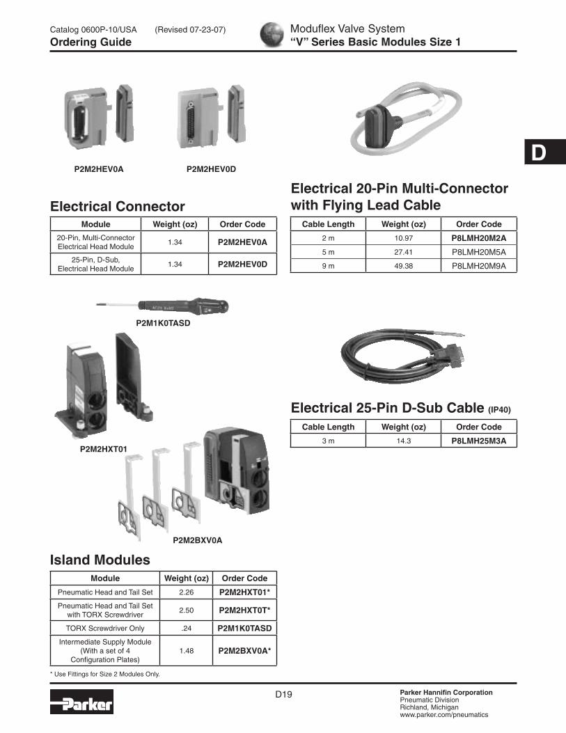
Electrical ConnectorModule Weight (oz) Order Code
20-Pin, Multi-Connector Electrical Head Module
1.34 P2M2HEV0A
25-Pin, D-Sub, Electrical Head Module
1.34 P2M2HEV0D
Moduflex Valve System“V” Series Basic Modules Size 1
Catalog 0600P-10/USA
Ordering Guide
P2M2HEV0A P2M2HEV0D
Electrical 20-Pin Multi-Connector with Flying Lead Cable
Cable Length Weight (oz) Order Code
2 m 10.97 P8LMH20M2A
5 m 27.41 P8LMH20M5A
9 m 49.38 P8LMH20M9A
Electrical 25-Pin D-Sub Cable (IP40)
Cable Length Weight (oz) Order Code
3 m 14.3 P8LMH25M3AP2M2HXT01
P2M2BXV0A
P2M1K0TASD
Island ModulesModule Weight (oz) Order Code
Pneumatic Head and Tail Set 2.26 P2M2HXT01*
Pneumatic Head and Tail Set with TORX Screwdriver
2.50 P2M2HXT0T*
TORX Screwdriver Only .24 P2M1K0TASD
Intermediate Supply Module (With a set of 4
Configuration Plates)1.48 P2M2BXV0A*
* Use Fittings for Size 2 Modules Only.
(Revised 07-23-07)

Parker Hannifin CorporationPneumatic DivisionRichland, Michiganwww.parker.com/pneumatics
D20
D
Size 2 Electro-Pneumatic Island Valve Modules, 24VDC
Moduflex Valve System“V” Series Basic Modules Size 2
Catalog 0600P-10/USA
Ordering Guide
“V” Series Basic Modules Size 2 (Without Pneumatic Connectors)
Single Solenoid Double Solenoid
Pneumatic Connectors for Size 2 Modules
Note: 85 Durometer minimum for pneumatic connectors.
MMDVA2PMDYY2
HMDXX2
Elbow Version Straight Version
Weight (oz)
Order Code
Weight(oz)
Order Code
Tube Push-in
Connector
6mm OD 0.18 CMD06-2 0.11 FMD06-2
1/4" OD 0.18 CMD07-2B 0.11 FMD07-2B
8mm OD 0.21 CMD08-2 0.14 FMD08-2
3/8" OD 0.21 CMD09-2B 0.14 FMD09-2B
10mm OD 0.25 CMD10-2 0.18 FMD10-2
12mm OD 0.28 CMD12-2 0.21 FMD12-2
1/2" OD — — 0.21 FMD13-2B
Muffler for Exhaust Port
— — — 0.11 MMDVA2
Plug — — — 0.18 PMDYY2
Double Male Union
(For Peripheral Valve Modules)
— — — 0.28 HMDXX2
4-Way / 2-Position / Single Valve
Solenoid Weight Part Number
Single Solenoid (Monostable)
3.53 oz P2M2V4ES2CV
Double Solenoid (Bistable)
3.88 oz P2M2V4EE2CV
3-Way / 2-Position / Dual Valve
Solenoid Weight Part Number
Double Solenoid NC + NC with Exhaust Check
4.06 oz P2M2VDEE2CV
Double Solenoid NO + NO with Exhaust Check
4.06 oz P2M2VCEE2CV
Double Solenoid NC + NO with Exhaust Check
4.06 oz P2M2VEEE2CV
Single Solenoid NC with Exhaust Check
3.88 oz P2M2V3ES2CV
Center Exhaust = dual 3/2 NC + NC without Exhaust Check
4.06 oz P2M2VGEE2CV
3
1
4 2
3
1
4 2
3
1
4 2
3
1
4 2
3
1
4
3 1
4 2
3 1
4 2
Note: Bold Options Standard
CMD09-2BFMD09-2B
(Revised 07-23-07)

Parker Hannifin CorporationPneumatic DivisionRichland, Michiganwww.parker.com/pneumatics
D21
DElectrical 20-Pin Multi-Connector with Flying Lead Cable
Cable Length Weight (oz) Order Code
2 m 10.97 P8LMH20M2A
5 m 27.41 P8LMH20M5A
9 m 49.38 P8LMH20M9A
Electrical 25-Pin D-Sub Cable (IP40)
Cable Length Weight (oz) Order Code
3 m 14.3 P8LMH25M3A
Electrical ConnectorModule Weight (oz) Order Code
20-Pin, Multi-Connector Electrical Head Module
1.34 P2M2HEV0A
25-Pin, D-Sub, Electrical Head Module
1.34 P2M2HEV0D
P2M2HEV0A P2M2HEV0D
Moduflex Valve System“V” Series Basic Modules Size 2
Catalog 0600P-10/USA
Ordering Guide
* Use Fittings for Size 2 Modules Only.
P2M2HXT01
P2M2BXV0A
P2M1K0TASD
Island ModulesModule Weight (oz) Order Code
Pneumatic Head and Tail Set 2.26 P2M2HXT01*
Pneumatic Head and Tail Set with TORX Screwdriver
2.50 P2M2HXT0T*
TORX Screwdriver Only .24 P2M1K0TASD
Intermediate Supply Module (With a set of 4
Configuration Plates)1.48 P2M2BXV0A*
(Revised 07-23-07)

Parker Hannifin CorporationPneumatic DivisionRichland, Michiganwww.parker.com/pneumatics
D22
D
Moduflex Valve System“V” Series Complete Modules
Catalog 0600P-10/USA
Model Number Index
“V” Series Island Valve Modules Model Number Index Complete Modules (Complete with Pneumatic and Electrical Connectors)
With Only One Universal Solenoid Pilot for all Configurations24VDC is now a global standard for all machines.
The Moduflex 24VDC unique solenoid pilot is supplied with the multi-function manual override that can be adapted to all requirements, as explained by the drawings.
Multi-Function Adaptable Manual Override
1. Push - Release
3. Remove Lock Capability
4. Manual Override is Totally Isolated
2. Push - Twist - Lock
LockingStop
IsolationFork
BOLD OPTIONS ARE MOST POPULAR.
Basic SeriesValvetronic Modules P2M
SizeSize 1 1Size 2 2
Valve Type / Function3-Way / 2-Position
Single Solenoid, NC Spring Return 3ES4-Way / 2-Position
Single Solenoid, Spring Return 4ESDouble Solenoid 4EE
Dual 3-Way, 2-Position, Spring ReturnSolenoid, NC / NC + PO Check (4/3 APB) BEE*Solenoid, NO / NO (4/3 Pressure Ctr.) CEESolenoid, NC / NC with Exhaust Check DEESolenoid, NO / NC with Exhaust Check EEESolenoid, NC / NC without Check (4/3 Exh. Ctr.) GEE
Dual 4-Way, 2-Position, Spring ReturnSolenoid JEE**
* Valve includes peripheral P. O. Check Valve and union fittings.** Size 1 Only.
LED / CableV0 No Cable with LED and Surge Suppression
P2M 1 V 4ES 2C 00 0 F4
Valve SeriesValvetronic V
Ports 1 & 30 None
Ports 2 & 4C0* 10mm Elbow FittingC2* 12mm Elbow FittingC4 5/32" (4mm) Elbow FittingC6 6mm Elbow FittingC7 1/4" Elbow FittingC8* 8mm Elbow FittingC9* 3/8" Elbow FittingF0* 10mm Elbow FittingF2* 12mm Elbow FittingF3* 1/2" Straight FittingF4 5/32" (4mm) Straight FittingF6 6mm Straight FittingF7 1/4" Straight FittingF8* 8mm Straight FittingF9* 3/8" Straight Fitting* Only Available with Size 2 Valves.
Operator Voltage2C 24VDC

Parker Hannifin CorporationPneumatic DivisionRichland, Michiganwww.parker.com/pneumatics
D23
D
Moduflex Valve System“V” Series Assemblies & Components
Catalog 0600P-10/USA
Ordering Information
How to Order Complete Valve AssemblyLine Item Quantity Part Number Description
1 1 P2M2V4ES2CV00F7Size 1, V Series Island Valve Module, 4 Way, Single Solenoid, LED / Surge Suppression, 1/4” OD Straight Port Fittings
“V” Series Single Solenoid
Notes: 1. LED and Surge Suppressor included with valve.2. To assemble into a manifold, Pneumatic Head and Tail Set and
Electrical Connector must be ordered separately.
Example:Size 1, 4-Way Single Solenoid valve with 1/4" Straight Connectors in Ports 2 and 4. Valve to include LED and surge suppression.
How to Order ComponentsLine Item Quantity Part Number Description
1 1 P2M1V4ES2CV Size 1, V Series Island Valve Module, Single Solenoid, 4 Way
2 2 FMD07-1B Size 1, 1/4” OD Tube Push In Connector

Parker Hannifin CorporationPneumatic DivisionRichland, Michiganwww.parker.com/pneumatics
D24
D
Moduflex Valve System“V” Series Wiring and Addressing
Catalog 0600P-10/USA
Technical Information
1
2
3
4
5
6
7
8
9
10
11
12
13
Black
Brown
Red
Orange
Yellow
Green
Blue
Purple
Gray
White
2
4
6
8
10
12
14
16
18
Not Used
Not Used
Not Used
Brown / White
Red / White
Orange / White
Green / White
Blue / White
Purple / White
Red / Black
Orange / Black
Yellow / Black
14
15
16
17
18
19
20
21
22
23
24
25
Address
Color Color
1
3
5
7
9
11
13
15
17
19
Not Used
Not Used
Common
AddressPin
NumberPin
Number
Face View - Male D-Sub, 25-Pin Head Module Connector
“V” Series 25-Pin, D-Sub Addressing
Electrical SpecificationsRated Voltage 24 VDC
Maximum Addresses 19
Maximum Energized Simultaneously
19
Electrical Connection25-Pin, D-Sub DIN41652, MIL-C-24308, NFC93425
Type HE5
Polarity Insensitive: PNP and NPN compatible
Dust and Water Protection IP40
P8LMH253A - Cable
Electrical 25-Pin D-Sub Cable (IP40)
Cable Length Weight (oz) Order Code
3 m 14.3 P8LMH25M3A
Valve Island Head 25-Pin, Multi-Connector On the island head module, the multi-connector integrates the HE10 connector standard in its 25-Pin version.
Its plug-in function is secured in position with a guillotine lock with easy access from the front of the island.
The 25-Pin, D-Sub multi-connector is rated for IP40.
25-Pin, Multi-Connector Addressing When assembling a V Series island, modules are automatically connected to the head module through the modular principle of the integrated electrical connections.
Each wire color code corresponds a solenoid pilot position in the island.
Face View - Female D-Sub, 25-Pin Cable Connector
1
2
3
4
5
6
7
8
9
10
11
12
13
Black
Brown
Red
Orange
Yellow
Green
Blue
Purple
Gray
White
2
4
6
8
10
12
14
16
18
Not Used
Not Used
Not Used
Brown / White
Red / White
Orange / White
Green / White
Blue / White
Purple / White
Red / Black
Orange / Black
Yellow / Black
14
15
16
17
18
19
20
21
22
23
24
25
Address
ColorColor
1
3
5
7
9
11
13
15
17
19
Not Used
Not Used
Common
AddressPin
NumberPin
Number
Parker Hannifin CorporationPneumatic DivisionRichland, Michiganwww.parker.com/pneumatics
D25
D
Moduflex Valve System“V” Series Wiring and Addressing
Catalog 0600P-10/USA
Technical Information
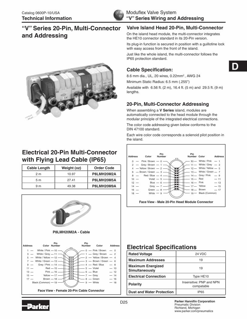
“V” Series 20-Pin, Multi-Connector and Addressing
Valve Island Head 20-Pin, Multi-Connector On the island head module, the multi-connector integrates the HE10 connector standard in its 20-Pin version.
Its plug-in function is secured in position with a guillotine lock with easy access from the front of the island.
Just like the whole island, the multi-connector follows the IP65 protection standard.
Cable Specification:8.6 mm dia., UL, 20 wires, 0.22mm2 , AWG 24
Minimum Static Radius: 6.5 mm (.255")
Available with 6.56 ft. (2 m), 16.4 ft. (5 m) and 29.5 ft. (9 m) lengths.
20-Pin, Multi-Connector Addressing When assembling a V Series island, modules are automatically connected to the head module through the modular principle of the integrated electrical connections.
The color code addressing given below conforms to the DIN 47100 standard.
Each wire color code corresponds a solenoid pilot position in the island.
Face View - Female 20-Pin Cable Connector
P8LMH20M2A - Cable
Electrical SpecificationsRated Voltage 24 VDC
Maximum Addresses 19
Maximum Energized Simultaneously
19
Electrical Connection Type HE10
Polarity Insensitive: PNP and NPN compatable
Dust and Water Protection IP65
Electrical 20-Pin Multi-Connector with Flying Lead Cable (IP65)
Cable Length Weight (oz) Order Code
2 m 10.97 P8LMH20M2A
5 m 27.41 P8LMH20M5A
9 m 49.38 P8LMH20M9A
0
1
2
3
4
5
6
7
8
9
10
11
12
13
14
15
16
17
18
19
Color
Color
PinNumber
PinNumber
Pink / Brown
Grey / Brown
Yellow / Brown
Brown / Green
Red / Blue
Violet
Blue
Grey
Green
White
White / Pink
White / Grey
White / Yellow
White / Green
Grey / Pink
Red
Pink
Yellow
Brown
Black (Common)
1
3
5
7
9
11
13
15
17
Address
0
2
4
6
8
10
12
14
16
18
Address
Face View - Male 20-Pin Head Module Connector
Pink / Brown
Grey / Brown
Yellow / Brown
Brown / Green
Red / Blue
Violet
Blue
Grey
Green
White
White / Pink
White / Grey
White / Yellow
White / Green
Grey / Pink
Red
Pink
Yellow
Brown
Black (Common)
0
1
2
3
4
5
6
7
8
9
10
11
12
13
14
15
16
17
18
19
1
3
5
7
9
11
13
15
17
Color
Color
Address
0
2
4
6
8
10
12
14
16
18
Address
PinNumber
PinNumber
Parker Hannifin CorporationPneumatic DivisionRichland, Michiganwww.parker.com/pneumatics
D26
D
Moduflex Valve System“V” Series Field Bus Connection Modules
Catalog 0600P-10/USA
Ordering Guide
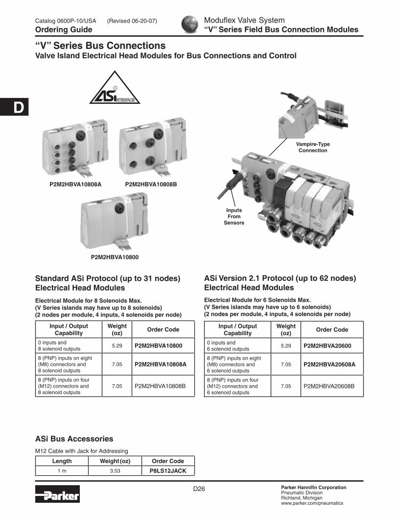
“V” Series Bus Connections Valve Island Electrical Head Modules for Bus Connections and Control
Electrical Module for 8 Solenoids Max.(V Series islands may have up to 8 solenoids)(2 nodes per module, 4 inputs, 4 solenoids per node)
Electrical Module for 6 Solenoids Max.(V Series islands may have up to 6 solenoids)(2 nodes per module, 4 inputs, 4 solenoids per node)
Input / Output Capability
Weight (oz)
Order Code
0 inputs and 8 solenoid outputs
5.29 P2M2HBVA10800
8 (PNP) inputs on eight (M8) connectors and 8 solenoid outputs
7.05 P2M2HBVA10808A
8 (PNP) inputs on four (M12) connectors and 8 solenoid outputs
7.05 P2M2HBVA10808B
Standard ASi Protocol (up to 31 nodes) Electrical Head Modules
ASi Version 2.1 Protocol (up to 62 nodes) Electrical Head Modules
Input / Output Capability
Weight (oz)
Order Code
0 inputs and 6 solenoid outputs
5.29 P2M2HBVA20600
8 (PNP) inputs on eight (M8) connectors and 6 solenoid outputs
7.05 P2M2HBVA20608A
8 (PNP) inputs on four (M12) connectors and 6 solenoid outputs
7.05 P2M2HBVA20608B
ASi Bus AccessoriesM12 Cable with Jack for Addressing
Length Weight (oz) Order Code
1 m 3.53 P8LS12JACK
P2M2HBVA10800
P2M2HBVA10808A P2M2HBVA10808B
Inputs From
Sensors
Vampire-Type Connection
(Revised 06-20-07)

Parker Hannifin CorporationPneumatic DivisionRichland, Michiganwww.parker.com/pneumatics
D27
D
Moduflex Valve SystemASi Bus Addressing, Diagnostic & Input Wiring
Catalog 0600P-10/USA
Technical Information
“V” Series ASi Bus Module: Addressing, Diagnostic, Input Wiring Bus Addressing, First and Second Node
3
41 34
134
5
21
I
II
III
IV
V
VI
VII
VIII
III
IIIIV
VVI
VII VIII
Pin Out1 - 24VDC / ASi2 - Second Input3 - 0VDC / ASi4 - First Input5 - Not Connected
Pin Out1 - 24VDC / ASi3 - 0VDC / ASi4 - Input
Note: With only one node, the inputs II and IV are connected to the connections on the right.
Input WiringPhysical Input (I, II, III, IV) = D (0 1 2 3) First Node, Physical Input (V, VI, VII, VIII) = D (0 1 2 3) Second Node.
M8 Female Connectors M12 Female Connectors
Bus DiagnosticInput LED D (0 1 2 3) (See Examples Below)
First Node LEDs State Second Node LEDs StateSystem Condition
Green LED Red LED Green LED Red LED
W m W m Normal Operation
m m m m No Module + Sensor Supply
m T m T Input Overload
m W m T No ASi Communication
T W m T Address First Node = 0
W m T W Address Second Node = 0W ON m OFF T BLINK
Green Red
LED and Input Area for First Node LED and Input Area
for Second Node
ASi Yellow Cable Bus Signals + Bus Module and Sensors Supply
ASi Black Cable 24VDC Output Supply (Sol. Pilots)*
Second Node AddressingFirst Node Addressing
Unscrewing the plug gives access to the jacks shown here.
ASi Standard 2 Nodes of 4I / 4O
ASi Version 2-1 2 Nodes of 4I / 3O
Address the first node in the first step.
Profile: S - 7 . F . E . V2.0 S - 7 . A . E . V2.1
“Power” LED State Off Green RedPower Supply Sol. Pilot Supply Normal Operation Solenoid Overload
Examples: Physical Input III = Logical Input 6.2, Physical Input V = Logical Input 7.0.
White Area for Address Marking
Green Red
+ –
+ –
0 1 2 3 0 1 2 3 0 1 2 0 1 2
1st Node 2nd Node1st
Node2nd
Node
I
II
III
IV
V
VI
VII
VIII
I
II
III
IV
V
VI
VII
VIII
* The external supply should have protective isolation in accordance with IEC 364-4-41 (PELV).
Parker Hannifin CorporationPneumatic DivisionRichland, Michiganwww.parker.com/pneumatics
D28
D
Bus Protocol
Connector Type
Weight (oz)
Order Code
Power Supply Female Straight Connector
Profibus DP / Interbus S
M12 type A 0.88 P8CS1205AA
DeviceNet /CANopen
M12 type B 0.88 P8CS1205AB
Line Termination Resistor
Profibus DP M12 type B 0.88 P8BPA00MB
DeviceNet / CANopen
M12 type A 0.88 P8BPA00MA
Note: Use standard cables and connectors for bus communications from your electrical supplier.
Electrical Module for 16 Outputs Max.(V Series islands may have up to 16 solenoids)
INTERBUS-SINTERBUS-S
Device Bus Electrical Head Modules
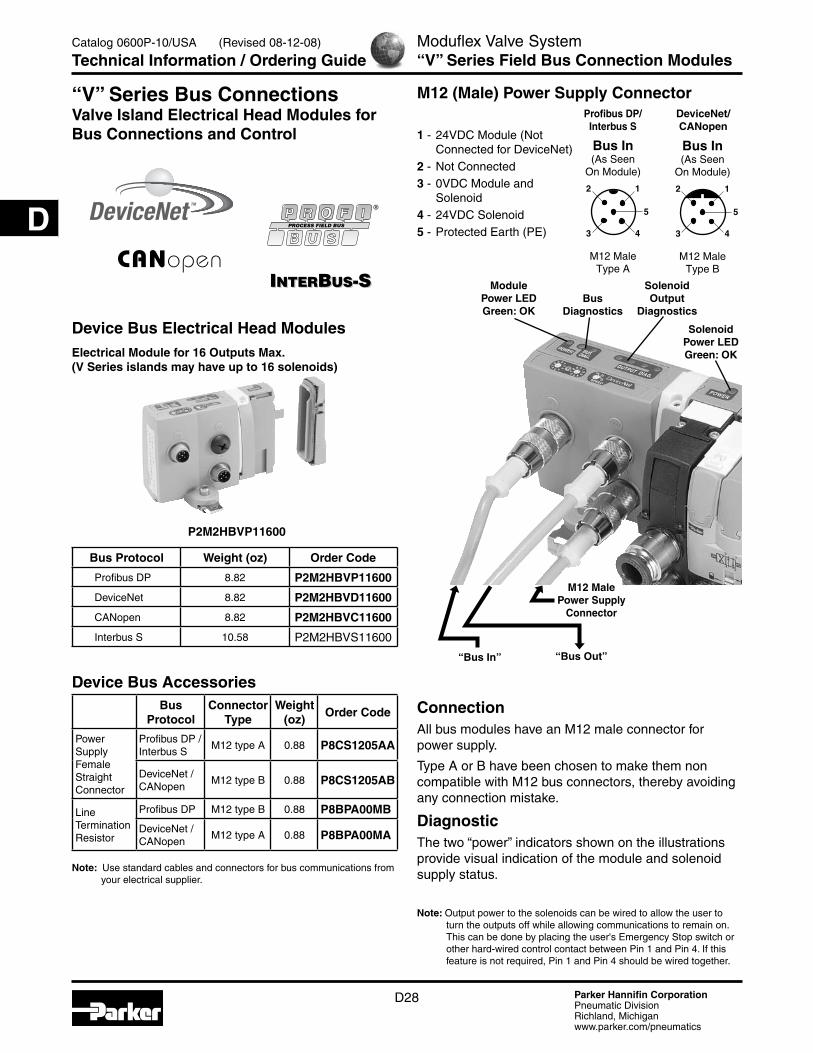
Bus Protocol Weight (oz) Order Code
Profibus DP 8.82 P2M2HBVP11600
DeviceNet 8.82 P2M2HBVD11600
CANopen 8.82 P2M2HBVC11600
Interbus S 10.58 P2M2HBVS11600
Device Bus Accessories
P2M2HBVP11600
Moduflex Valve System“V” Series Field Bus Connection Modules
Catalog 0600P-10/USA
Technical Information / Ordering Guide
“V” Series Bus Connections Valve Island Electrical Head Modules for Bus Connections and Control
M12 Male Power Supply
Connector
“Bus In”
Solenoid Power LED Green: OK
“Bus Out”
1 - 24VDC Module (Not Connected for DeviceNet)2 - Not Connected 3 - 0VDC Module and Solenoid4 - 24VDC Solenoid5 - Protected Earth (PE)
Profibus DP/Interbus S
DeviceNet/CANopen
M12 (Male) Power Supply Connector
2 1
3 4
5
Bus In(As Seen
On Module)
M12 MaleType A
2 1
3 4
5
Bus In(As Seen
On Module)
M12 MaleType B
ConnectionAll bus modules have an M12 male connector for power supply.
Type A or B have been chosen to make them non compatible with M12 bus connectors, thereby avoiding any connection mistake.
DiagnosticThe two “power” indicators shown on the illustrations provide visual indication of the module and solenoid supply status.
Note: Output power to the solenoids can be wired to allow the user to turn the outputs off while allowing communications to remain on. This can be done by placing the user's Emergency Stop switch or other hard-wired control contact between Pin 1 and Pin 4. If this feature is not required, Pin 1 and Pin 4 should be wired together.
BusDiagnostics
Solenoid Output
Diagnostics
Module Power LED Green: OK
(Revised 08-12-08)

Parker Hannifin CorporationPneumatic DivisionRichland, Michiganwww.parker.com/pneumatics
D29
D
Solenoid Pilot Diagnostic Common to All Device Bus Modules
Inside the bus module, solenoid valve control is protected against short-circuits with the following visual indication provided:
• The red LEDs with code, shown above, detect solenoid valve short-circuits.
• Supply is OK when the solenoid pilot power supply indicator is green.
Moduflex Valve SystemDevice Bus Module
Catalog 0600P-10/USA
Technical Information
0 1 23
45678
9 0 1 23
45678
9
POWERPOWER
BUS DIAG. OUTPUT DIAG.
A A: Solenoid Pilots 0 to 3 B: Solenoid Pilots 4 to 7 C: Solenoid Pilots 8 to 11 D: Solenoid Pilots 12 to 15B C D
0 1 2 3 4 5 6 7 8 9 10 11 12 13 14 15
Red LED's Detecting Solenoid Valve Short Circuits
Green Solenoid Pilot Supply OK Solenoid LED's
Bus Cable Protection Shield Connections for Profibus DP, DeviceNet and CANopenTo provide protection against electro-magnetic interferences, the bus cables are shielded. The module “bus in” and “bus out” connectors each includes a pin for connecting the cable shield (see next pages). It is safer to connect the shield to the protected earth (PE) at both ends of the bus. Within the bus module, provision is made to enable shield continuity by connection between the two shield pins.
The protected earth have to be connected locally on each module for CE accordance.
Power
Protected Earth (PE)
Internal Use
Bus In Bus Out
BusCable Shield

Parker Hannifin CorporationPneumatic DivisionRichland, Michiganwww.parker.com/pneumatics
D30
D
Moduflex Valve SystemDevice Bus Module
Catalog 0600P-10/USA
Technical Information
“V” Series ValvetronicTM Device Bus Module: Connections, Addressing, Diagnostic
Bus Cable ConnectionsProfibus DP standard male and female type B M12 connectors.
Use of prefabricated cables available from your local electrical supplier is recommended.
Line termination P8BPA00MB, is necessary on the “bus out” connector of the last station.
This module incorporates an Autobaud detect feature, eliminating the need to set switches.
AddressingUse the GSD file on web site .
The rotary switches enable configuration of the decimal address.
• www.parker.com/moduflex
DiagnosticDiagnostic according to the module dialog shown on the illustration.
Bus Cable ConnectionsDeviceNet standard male and female type A M12 connectors.
Use of prefabricated cables available from your local electrical supplier is recommended.
Line termination P8BPA00MA, is necessary on the “bus out” connector of the last station.
AddressingUse the EDS file on web site .
The rotary switches enable configuration of the node address (MAC ID) and the baud rate.
• www.parker.com/moduflex
DiagnosticDiagnostic according to the module dialog shown on the illustration.
Pin Out1 - + 5V
2 - Line A
3 - 0V
4 - Line B
5 - Shield
Pin Out1 - Drain
2 - 24VDC
3 - 0VDC
4 - CAN-H
5 - CAN-L
2 1
3 4
5
1 2
4 3
5
0 1 23
45678
9 0 1 23
45678
9
POWERPOWER
BUS DIAG. OUTPUT DIAG.
Bus In(As Seen
On Module)
Bus Out(As Seen
On Module)
M12 MaleType B
M12 FemaleType B
Bus Active Diagnostic Error
Address 1-99
Solenoid Pilot Diagonostic
Profibus DP
2 1
3 4
5
1 2
4 3
5
0 1 23
45678
9 V1 V2V
0
0 1 23
45678
9
POWERPOWER
BUS DIAG. OUTPUT DIAG.
Bus In(As Seen
On Module)
Bus Out(As Seen
On Module)
M12 MaleType A
M12 FemaleType A
Bus ActiveBus
Communication Error
Baud RateV0: 125 K BaudV1: 250 K BaudV2: 500 K Baud
MAC ID 1-63
Solenoid Pilot Diagonostic
DeviceNet

Parker Hannifin CorporationPneumatic DivisionRichland, Michiganwww.parker.com/pneumatics
D31
D
Moduflex Valve SystemDevice Bus Module
Catalog 0600P-10/USA
Technical Information
Bus Cable ConnectionsCANopen standard male and female type A M12 connectors.
Use of prefabricated cables available from your local electrical supplier is recommended.
Line termination P8BPA00MA, is necessary on the “bus out” connector of the last station.
AddressingUse the EDS file on web site.
The rotary switches enable configuration of the decimal address.
• www.parker.com/moduflex
DiagnosticDiagnostic according to the module dialog shown on the illustration.
Pin Out1 - CAN_SHLD
2 - CAN_V+
3 - CAN_GND
4 - CAN_H
5 - CAN_L
2 1
3 4
5
1 2
4 3
5
0 1 23
45678
9 V1 V2V
0
0 1 23
45678
9
POWERPOWER
BUS DIAG. OUTPUT DIAG.
Bus In(As Seen
On Module)
Bus Out(As Seen
On Module)
M12 MaleType A
M12 FemaleType A
CAN Run LED Error LED
Baud RateV0: 20 K BaudV1: 125 K BaudV2: 250 K BaudOthers: Auto Detection (10K Baud) - 1M Baud
Equipment Node-ID 01-99
Solenoid Pilot Diagonostic
CAN open
CAN_V+ : 24VDC module supply
Bus Cable ConnectionsThe M23 connectors conform to “Interbus remote bus”.
Use of prefabricated cables available from your usual electrical supplier is recommended.
This module operates at 500 kbps.
AddressingInterbus S is self addressing; therefore, it does not need any software or hardware configuration.
DiagnosticDiagnostic according to the module dialog shown on the illustration.
This diagnostic conforms to the Interbus S standard.
Pin Out 1 - D0
2 - D0
3 - DI
4 - DI
5 - Ground
6 - PE
7 - +24V
8 - 0V
9 - RBST
Note: For more details, please consult “Interbus remote bus” documentation.
INTERBUS-SINTERBUS-S
Pin Out 1 - D0
2 - D0
3 - DI
4 - DI
5 - Ground
6 - PE
7 - +24V
8 - 0V
9 - NC
8 1
7 2
6 3
5 4
9
POWERPOWER
BUS DIAG. OUTPUT DIAG.
Bus In(As Seen
On Module)
Bus Out(As Seen
On Module)
M23 Male M23 Female
Remote Bus Check
Bus Active
Remote BusDisabled
Solenoid Pilot Diagonostic
1 8
2 7
3 6
4 5
9
Interbus S

Parker Hannifin CorporationPneumatic DivisionRichland, Michiganwww.parker.com/pneumatics
D32
D
Moduflex Valve SystemDevice Bus Module
Catalog 0600P-10/USA
Technical Information
All Buses EMC / CE Mark According to EN 61 000-6-2 EN 50081-2
ASi Bus
ASi Line According to EN 50295
Solenoid Pilot Voltage 24VDC
Module Consumption max. 70 mA (2 nodes)
Max. Supply for All Inputs 240 mA (including internal input consumption)
Internal Input Consump. 9 mA for each active input
Inputs According to IEC 1131-2 class 2
CertificationThese products have been developed according to the association complete specification (v.2.11) and to the slave profiles S-7.F.E or S-B.F.E
Device Bus
Bus Line According to each bus specification
Module Voltage 20 to 30VDC
Solenoid Pilot Voltage 24VDC
Module Consumption Profibus DP max. 1.5WDeviceNet / CANopen max. 1.5W
Interbus S max. 2W
Outputs Overload protection
Certification
DeviceNet: Compliant to Composite Test Revision 17, Test Suite: M002
Profibus-DP: Compliant to Test Specifications for Profibus DP Slaves, Version 2.0, February 2000, based on EN 50170-2 at Siemens AG in Furth.
Interbus-S: This product has passed the relevant tests in accordance with the Interbus conformance requirements Certified No. 385.
Serial Bus Specifications
Parker Hannifin CorporationPneumatic DivisionRichland, Michiganwww.parker.com/pneumatics
D33
D
Catalog 0600P-10/USA
Technical Information
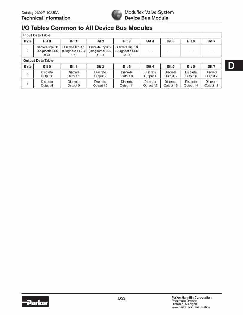
I/O Tables Common to All Device Bus ModulesInput Data Table
Byte Bit 0 Bit 1 Bit 2 Bit 3 Bit 4 Bit 5 Bit 6 Bit 7
0Discrete Input 0 (Diagnostic LED
0-3)
Discrete Input 1 (Diagnostic LED
4-7)
Discrete Input 2 (Diagnostic LED
8-11)
Discrete Input 3 (Diagnostic LED
12-15)— — — —
Output Data Table
Byte Bit 0 Bit 1 Bit 2 Bit 3 Bit 4 Bit 5 Bit 6 Bit 7
0Discrete Output 0
Discrete Output 1
Discrete Output 2
Discrete Output 3
Discrete Output 4
Discrete Output 5
Discrete Output 6
Discrete Output 7
1Discrete Output 8
Discrete Output 9
Discrete Output 10
Discrete Output 11
Discrete Output 12
Discrete Output 13
Discrete Output 14
Discrete Output 15
Moduflex Valve SystemDevice Bus Module
Parker Hannifin CorporationPneumatic DivisionRichland, Michiganwww.parker.com/pneumatics
D34
D
Moduflex Valve SystemSize 1 Pressure Regulators
Catalog 0600P-10/USA
Accessories
Note: 85 Durometer minimum for pneumatic connectors.
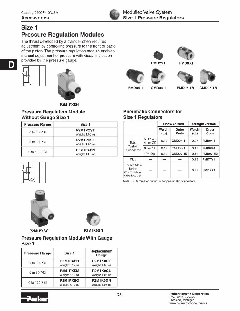
Size 1 Pressure Regulation ModulesThe thrust developed by a cylinder often requires adjustment by controlling pressure to the front or back of the piston. The pressure regulation module enables manual adjustment of pressure with visual indication provided by the pressure gauge.
Pressure Regulation Module With Gauge Size 1
Pressure Range Size 1 Replacement Gauge
0 to 30 PSI P2M1PXSR Weight 5.12 oz
P2M1K0GT Weight 1.06 oz
0 to 60 PSI P2M1PXSM Weight 5.12 oz
P2M1K0GL Weight 1.06 oz
0 to 120 PSI P2M1PXSG Weight 5.12 oz
P2M1K0GN Weight 1.06 oz
P2M1PXSN
P2M1PXSG
Pressure Regulation Module Without Gauge Size 1
Pressure Range Size 1
0 to 30 PSI P2M1PXST Weight 4.06 oz
0 to 60 PSI P2M1PXSL Weight 4.06 oz
0 to 120 PSI P2M1PXSN Weight 4.06 oz
P2M1K0GN
PMDYY1
FMD04-1 CMD04-1 FMD07-1B CMD07-1B
HMDXX1
Pneumatic Connectors for Size 1 Regulators
Elbow Version Straight Version
Weight (oz)
Order Code
Weight(oz)
Order Code
Tube Push-in
Connector
5/32" = 4mm OD
0.18 CMD04-1 0.07 FMD04-1
6mm OD 0.18 CMD06-1 0.11 FMD06-1
1/4" OD 0.18 CMD07-1B 0.11 FMD07-1B
Plug — — — 0.18 PMDYY1
Double Male Union
(For Peripheral Valve Modules)
— — — 0.21 HMDXX1

Parker Hannifin CorporationPneumatic DivisionRichland, Michiganwww.parker.com/pneumatics
D35
D
Pressure Regulation Module Without Gauge Size 2
Pressure Range Size 2
0 to 30 PSI P2M2PXST Weight 6.00 oz
0 to 60 PSI P2M2PXSL Weight 6.00 oz
0 to 120 PSI P2M2PXSN Weight 6.00 oz
Note: 85 Durometer minimum for pneumatic connectors.
Pressure Regulation Module With Gauge Size 2
Pressure Range Size 2 Replacement
Gauge
0 to 30 PSI P2M2PXSR Weight 4.94 oz
P2M1K0GT Weight 1.06 oz
0 to 60 PSI P2M2PXSM Weight 4.94 oz
P2M1K0GL Weight 1.06 oz
0 to 120 PSI P2M2PXSG Weight 4.94 oz
P2M1K0GN Weight 1.06 oz
P2M2PXSN
P2M2PXSR
Moduflex Valve SystemSize 2 Pressure Regulators
Catalog 0600P-10/USA
Accessories
Size 2 Regulation ModulesThe thrust developed by a cylinder often requires adjustment by controlling pressure to the front or back of the piston. The pressure regulation module enables manual adjustment of pressure with visual indication provided by the pressure gauge.
P2M1K0GN
PMDYY2
HMDXX2
Pneumatic Connectors for Size 2 Regulators
Elbow Version Straight Version
Weight (oz)
Order Code
Weight(oz)
Order Code
Tube Push-in
Connector
6mm OD 0.18 CMD06-2 0.11 FMD06-2
1/4" OD 0.18 CMD07-2B 0.11 FMD07-2B
8mm OD 0.21 CMD08-2 0.14 FMD08-2
3/8" OD 0.21 CMD09-2B 0.14 FMD09-2B
10mm OD 0.25 CMD10-2 0.18 FMD10-2
12mm OD 0.28 CMD12-2 0.21 FMD12-2
1/2" OD — — 0.21 FMD13-2B
Plug — — — 0.18 PMDYY2
Double Male Union
(For Peripheral Valve Modules)
— — — 0.28 HMDXX2
CMD09-2BFMD09-2B
(Revised 07-23-07)

Parker Hannifin CorporationPneumatic DivisionRichland, Michiganwww.parker.com/pneumatics
D36
D
Moduflex Valve SystemCheck Valve Module
Catalog 0600P-10/USA
Accessories
Dual P.O. Check Valve Size 1
Description Size 1
Dual Pilot Operated P2M1PXCA Weight .88 oz
Dual P.O. Check ValveCombined with a double 3/2 NC + NC valve, this module will block both flows and stop cylinder movement as soon as the valve's outputs are both exhausted. Better than a 3-Position valve, it provides more precise positioning when fitted close to the cylinder. Standard with manual release buttons.
Note: 85 Durometer minimum for pneumatic connectors.
Pneumatic Connectors for Size 1 Dual P.O. Check Valves
Note: 85 Durometer minimum for pneumatic connectors.
Pneumatic Connectors for Size 2 Dual P.O. Check Valves
HMDXX2
FMD04-1 CMD04-1 FMD07-1B CMD07-1B
HMDXX1
Dual P.O. Check Valve Size 2
Description Size 2
Dual Pilot Operated P2M2PXCA Weight .88 oz
ApplicationAt the outputs of a double 3/2 NC + NC valve, the dual P.O. check valve module achieves efficient and stable cylinder positioning. As soon as both lines are exhausted by the main control valve, the two internally piloted check valves close tight. The cylinder is then stabilized.
The manual pressure releases may then eventually be used for an adequate machine positioning.
3
1
4 2
Manual Release
Double 3/2 NC + NC
Cylinder
Dual P.O. CheckValve Module
P2M1PXCA
Elbow Version Straight Version
Weight (oz)
Order Code
Weight(oz)
Order Code
Tube Push-in
Connector
5/32" = 4mm OD
0.18 CMD04-1 0.07 FMD04-1
6mm OD 0.18 CMD06-1 0.11 FMD06-1
1/4" OD 0.18 CMD07-1B 0.11 FMD07-1B
Double Male Union
(For Peripheral Valve Modules)
— — — 0.21 HMDXX1
Elbow Version Straight Version
Weight (oz)
Order Code
Weight(oz)
Order Code
Tube Push-in
Connector
6mm OD 0.18 CMD06-2 0.11 FMD06-2
1/4" OD 0.18 CMD07-2B 0.11 FMD07-2B
8mm OD 0.21 CMD08-2 0.14 FMD08-2
3/8" OD 0.21 CMD09-2B 0.14 FMD09-2B
10mm OD 0.25 CMD10-2 0.18 FMD10-2
12mm OD 0.28 CMD12-2 0.21 FMD12-2
1/2" OD — — 0.21 FMD13-2B
Double Male Union
(For Peripheral Valve Modules)
— — — 0.28 HMDXX2
CMD09-2BFMD09-2B
(Revised 07-23-07)

Parker Hannifin CorporationPneumatic DivisionRichland, Michiganwww.parker.com/pneumatics
D37
D
Dual Flow ControlBy controlling the exhaust flows of a double-acting cylinder, this module can adjust both speeds — extend and retract. It may be plugged into the valve module output ports or mounted close to the cylinder in its in-line version.
Note: 85 Durometer minimum for pneumatic connectors.
Pneumatic Connectors for Size 1 Dual P.O. Check Valves
Note: 85 Durometer minimum for pneumatic connectors.
Pneumatic Connectors for Size 2 Dual P.O. Check Valves
HMDXX2
FMD04-1 CMD04-1 FMD07-1B CMD07-1B
HMDXX1
ApplicationOn a double-acting cylinder, extend and retract speeds are adjusted separately by control of air flow exhaust. The control becomes more precise when the flow adjustment is close to the cylinder. The examples show different solutions which are dependent upon the valve-to-cylinder distance and accessibility to the cylinder
3 1
4 2
Single 4/2 Monostable
Cylinder
Dual Flow Control
Dual Flow Control Size 1
Description Size 1
Dual Flow Control Module P2M1PXFA Weight 1.06 oz
Dual Flow Control Size 2
Description Size 2
Dual Flow Control Module P2M2PXFA Weight 1.59 oz
P2M1PXFA
Moduflex Valve SystemDual Flow Control
Catalog 0600P-10/USA
Accessories
Elbow Version Straight Version
Weight (oz)
Order Code
Weight(oz)
Order Code
Tube Push-in
Connector
5/32" = 4mm OD
0.18 CMD04-1 0.07 FMD04-1
6mm OD 0.18 CMD06-1 0.11 FMD06-1
1/4" OD 0.18 CMD07-1B 0.11 FMD07-1B
Double Male Union
(For Peripheral Valve Modules)
— — — 0.21 HMDXX1
Elbow Version Straight Version
Weight (oz)
Order Code
Weight(oz)
Order Code
Tube Push-in
Connector
6mm OD 0.18 CMD06-2 0.11 FMD06-2
1/4" OD 0.18 CMD07-2B 0.11 FMD07-2B
8mm OD 0.21 CMD08-2 0.14 FMD08-2
3/8" OD 0.21 CMD09-2B 0.14 FMD09-2B
10mm OD 0.25 CMD10-2 0.18 FMD10-2
12mm OD 0.28 CMD12-2 0.21 FMD12-2
1/2" OD — — 0.21 FMD13-2B
Double Male Union
(For Peripheral Valve Modules)
— — — 0.28 HMDXX2
CMD09-2BFMD09-2B
(Revised 07-23-07)

Parker Hannifin CorporationPneumatic DivisionRichland, Michiganwww.parker.com/pneumatics
D38
D
Moduflex Valve System“P” Series Complete Modules
Catalog 0600P-10/USA
Ordering Guide
“P” Series Peripheral Modules Model Number Index Complete Modules (Complete with Pneumatic Connectors)
BOLD OPTIONS ARE MOST POPULAR.
Basic SeriesElectro-Pneumatic Valve Modules P2M
SizeSize 1 1Size 2 2
Accessory TypeDual Pilot Operated Check CDual Flow Control FSingle Pressure Regulator S
P2M 1 PX S L F4 F4Ports 2 & 4 (S, T & V Series)
C0* 10mm Elbow FittingC2* 12mm Elbow FittingC4 5/32" (4mm) Elbow FittingC6 6mm Elbow FittingC7 1/4" Elbow FittingC8* 8mm Elbow FittingC9* 3/8" Elbow FittingF0* 10mm Elbow FittingF2* 12mm Elbow FittingF3* 1/2" Straight FittingF4 5/32" (4mm) Straight FittingF6 6mm Straight FittingF7 1/4" Straight FittingF8* 8mm Straight FittingF9* 3/8" Straight FittingJJ Double Male UnionPP Clip-In Plug* Only Available with Size 2 Valves.
Accessory OptionFlow Control or Pilot Operated Check A*0 - 120 PSI - Gauge G0 - 60 PSI - No Gauge L0 - 60 PSI - Gauge M0 - 120 PSI - No Gauge N0 - 30 PSI - Gauge R0 - 30 PSI - No Gauge T
* Must be used with Accessory Type “C” or “F”.
Ports 1 & 3 (Supply / Exhaust)C0* 10mm Elbow FittingC2* 12mm Elbow FittingC4 5/32" (4mm) Elbow FittingC6 6mm Elbow FittingC7 1/4" Elbow FittingC8* 8mm Elbow FittingC9* 3/8" Elbow FittingF0* 10mm Elbow FittingF2* 12mm Elbow FittingF3* 1/2" Straight FittingF4 5/32" (4mm) Straight FittingF6 6mm Straight FittingF7 1/4" Straight FittingF8* 8mm Straight FittingF9* 3/8" Straight FittingJJ Double Male Union* Only Available with Size 2 Valves.
Style / FunctionPeripheral PX
(Revised 03-18-08)

Parker Hannifin CorporationPneumatic DivisionRichland, Michiganwww.parker.com/pneumatics
D39
D
Moduflex Valve System“P” Series Assemblies & Components
Catalog 0600P-10/USA
Ordering Information
Regulator with Gauge
How to Order Complete Peripheral ModuleLine Item Quantity Part Number Description
1 1 P2M1PXSGF7F7 Size 1, Regulator with 0-160 PSI Gauge, 1/4" OD Straight Port Fittings in port 1, 2, 3, 4
How to Order ComponentsLine Item Quantity Part Number Description
1 1 P2M1PXSG Size 1, Regulator with 0-160 PSI Gauge
2 4 FMD07-1B Size 1-1/4" OD Tube Push-In Connector
How to Order Complete Peripheral ModuleLine Item Quantity Part Number Description
1 1 P2M1PXFAF7F7 Size 1, Dual Flow Control, 1/4" OD Straight Port Fittings in Port 1, 2, 3, 4
How to Order ComponentsLine Item Quantity Part Number Description
1 1 P2M1PXFA Size 1, Dual Flow Control
2 4 FMD07-1B Size 1-1/4" OD Tube Push-In Connector
Example:Size 1, Regulator with gauge, 1/4” OD straight fittings.
Example:Size 1, Dual Flow Control, 1/4” OD Straight Fittings.
Flow Control with Fittings
Parker Hannifin CorporationPneumatic DivisionRichland, Michiganwww.parker.com/pneumatics
D40
D
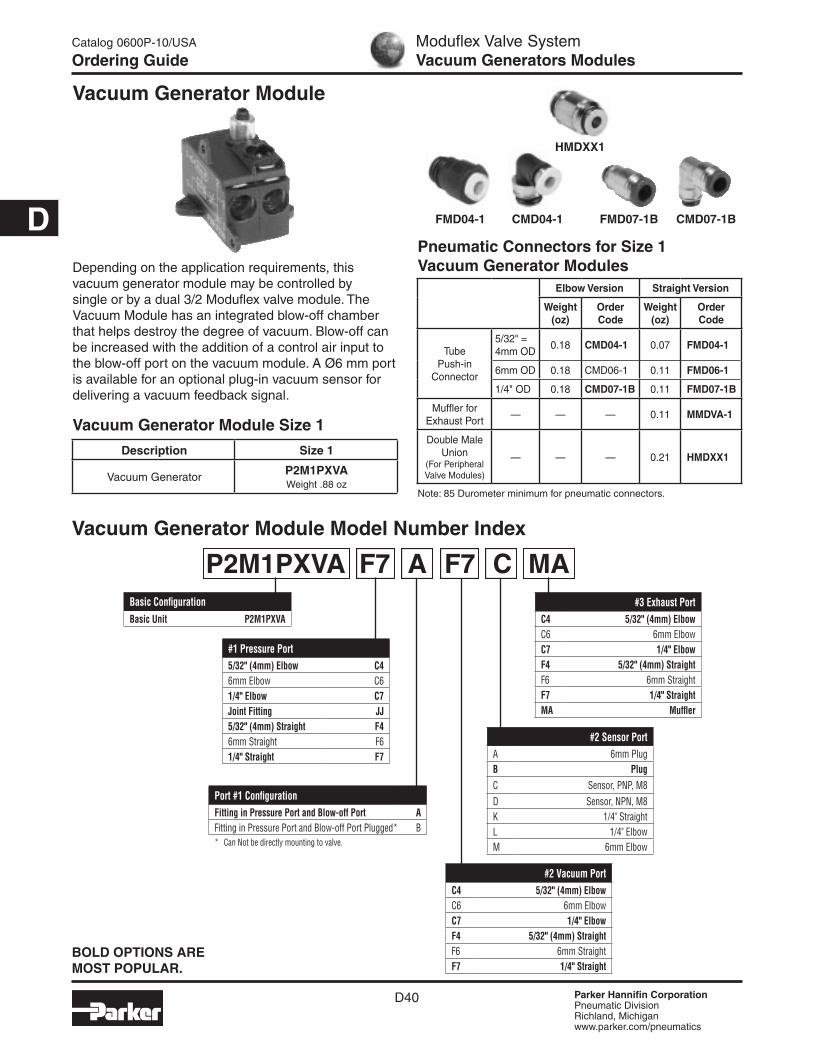
Vacuum Generator Module
Depending on the application requirements, this vacuum generator module may be controlled by single or by a dual 3/2 Moduflex valve module. The Vacuum Module has an integrated blow-off chamber that helps destroy the degree of vacuum. Blow-off can be increased with the addition of a control air input to the blow-off port on the vacuum module. A Ø6 mm port is available for an optional plug-in vacuum sensor for delivering a vacuum feedback signal.
Note: 85 Durometer minimum for pneumatic connectors.
Pneumatic Connectors for Size 1 Vacuum Generator Modules
FMD04-1 CMD04-1 FMD07-1B CMD07-1B
HMDXX1
Vacuum Generator Module Size 1
Description Size 1
Vacuum Generator P2M1PXVA Weight .88 oz
Moduflex Valve SystemVacuum Generators Modules
Catalog 0600P-10/USA
Ordering Guide
Vacuum Generator Module Model Number Index
Elbow Version Straight Version
Weight (oz)
Order Code
Weight(oz)
Order Code
Tube Push-in
Connector
5/32" = 4mm OD
0.18 CMD04-1 0.07 FMD04-1
6mm OD 0.18 CMD06-1 0.11 FMD06-1
1/4" OD 0.18 CMD07-1B 0.11 FMD07-1B
Muffler for Exhaust Port
— — — 0.11 MMDVA-1
Double Male Union
(For Peripheral Valve Modules)
— — — 0.21 HMDXX1
Basic ConfigurationBasic Unit P2M1PXVA
P2M1 PXVA F7 A F7 C MA
#1 Pressure Port5/32" (4mm) Elbow C46mm Elbow C61/4" Elbow C7Joint Fitting JJ5/32" (4mm) Straight F46mm Straight F61/4" Straight F7
Port #1 ConfigurationFitting in Pressure Port and Blow-off Port AFitting in Pressure Port and Blow-off Port Plugged* B* Can Not be directly mounting to valve.
#3 Exhaust PortC4 5/32" (4mm) ElbowC6 6mm ElbowC7 1/4" ElbowF4 5/32" (4mm) StraightF6 6mm StraightF7 1/4" StraightMA Muffler
#2 Vacuum PortC4 5/32" (4mm) ElbowC6 6mm ElbowC7 1/4" ElbowF4 5/32" (4mm) StraightF6 6mm StraightF7 1/4" Straight
#2 Sensor PortA 6mm PlugB PlugC Sensor, PNP, M8D Sensor, NPN, M8K 1/4" StraightL 1/4" ElbowM 6mm Elbow
BOLD OPTIONS ARE MOST POPULAR.

Parker Hannifin CorporationPneumatic DivisionRichland, Michiganwww.parker.com/pneumatics
D41
D
Moduflex Valve SystemVacuum Generator Modules
Catalog 0600P-10/USA
Ordering Guide
Single 3/2 NC Air Control ValveThe 3/2 valve delivers the air supply to generate vacuum through the venturi. It also pressurizes the integrated blow-off chamber. When the 3/2 valve cuts-off the air supply, this chamber is automatically exhausted into the vacuum channel in order to speed-up the part release. In this type of application, it is preferred to have the vacuum generator mounted away from the control valve.
Vacuum Generator Applications
Dual 3/2 3/2 Valve ControlOne 3/2 valve controls air supply for vacuum. The other 3/2 valve will generate an additional blow-off that may prove necessary to obtain quick part release from large vacuum pads. The effect of the blow-off can be controlled with an adjustable screw. In this type of circuit, the Vacuum Generator can be mounted directly to the valve by using Double Male Unions or as a stand alone item away from the control valve.
Electrical or Pneumatic Actuated Valves Vacuum
GeneratorVacuum Cup
Pressure Sensor
2
31
1 22
3
14
Check Valve Speed
Control
Exhaust
Venturi
Double Check Valve
3/2 Vacuum
Blow-off Reservoir
Electrical or Pneumatic Actuated Valves Vacuum
GeneratorVacuum Cup
Pressure Sensor
2
31
1 22
3
14
3/2 Blow-off
Check Valve Speed
Control
Exhaust
Venturi
Double Check Valve
3/2 Vacuum
Blow-off Reservoir
Vacuum Flow (SCFM)Nozzle
DiameterinHg
0 3 6 9 12 15 18 21 24 27 30
P2M1PXVA 0.84 0.76 0.67 0.55 0.42 0.30 0.18 0.06 — — —
Evacuation Time
Series / Nozzle Diameter
Air Supply Pressure
Air Consumption
Evacuation Time in sec / ft3 *
to reach different Vacuum Levels (inHg)
PSI SCFM 3 6 9 12 15 18 21 24 27
P2M1PXVA 70 1.60 5.6 14.2 22.0 42.4 62.3 85.0 116 198 —
* 1 ft3 = 28.31 liters
MPS-6 Sensor Ordering NumbersPressure Range Port Size Output Circuit Electrical Connector Part Number
0 to -30 inHg 6mm Tube StudPNP Sourcing
4 Pin, M8MPS-V6T-PC*
NPN Sinking MPS-V6T-NC*
Sensor Cable Part NumbersItem Connector Contacts Length Cover
CB-M8-4P-2M M8 Female 4 2m PVC
CB-M8-4P-5M M8 Female 4 5m PUR
* If ordering the sensor separate from the vacuum module, install a 6mm straight fitting in #2 sensor port for direct mounting.

Parker Hannifin CorporationPneumatic DivisionRichland, Michiganwww.parker.com/pneumatics
D42
D
Moduflex Valve SystemIntermediate Supply Module
Catalog 0600P-10/USA
Model Number Index, Plate Configuration
Intermediate Supply Module Model Number Index
#1 & #3 Blocked #1 Open, #3 Blocked #1 Blocked, #3 Open #1 & #3 Open
Plate Configuration
#1 Port connected to valves on the right only. Left is blocked.
#3 Port connected to valves on the right only. Left is blocked.
#1 Port connected to valves on the right and the left.
#3 Port connected to valves on the right only. Left is blocked.
#1 Port connected to valves on the right only. Left is blocked.
#3 Port connected to valves on the right and the left.
#1 Port connected to valves on the right and the left.
# 3 Port connected to valves on the right and the left.
BOLD OPTIONS ARE MOST POPULAR.
Intermediate Supply ModuleBasic Unit P2M2BX
Wiring StyleNo Cable 0
P2M2BX V 0 4 F9 MM
Valve TypeIndividually Wired TValvetronic Interconnect V
Exhaust Port Type (#3 Exhaust)*C0 10mm Elbow FittingC2 12mm Elbow FittingC6 6mm Elbow FittingC7 1/4" Elbow FittingC8 8mm Elbow FittingC9 3/8" Elbow FittingF0 10mm Elbow FittingF2 12mm Elbow FittingF3 1/2" Straight FittingF6 6mm Straight FittingF7 1/4" Straight FittingF8 8mm Straight FittingF9 3/8" Straight FittingMM Clip-In MufflerPP Clip-In Plug* Elbow Fittings Face Up.
Plate Configuration#1 & #3 Blocked 1#1 Open & #3 Blocked 2#1 Blocked & #3 Open 3#1 & #3 Open 4
Inlet Port Type (#1 Pressure)*C0 10mm Elbow FittingC2 12mm Elbow FittingC6 6mm Elbow FittingC7 1/4" Elbow FittingC8 8mm Elbow FittingC9 3/8" Elbow FittingF0 10mm Elbow FittingF2 12mm Elbow FittingF3 1/2" Straight FittingF6 6mm Straight FittingF7 1/4" Straight FittingF8 8mm Straight FittingF9 3/8" Straight FittingMM Clip-In MufflerPP Clip-In Plug* Elbow Fittings Face Up.

Parker Hannifin CorporationPneumatic DivisionRichland, Michiganwww.parker.com/pneumatics
D43
D
Moduflex Valve SystemInternal / External Pilot
Catalog 0600P-10/USA
Technical Information
Internal and External Pilot Supply OptionsAll T and V Series Valves subbases incorporate an auxiliary channel “X” to supply pressure to the solenoid pilots. The “X” galley is pressurized from the head module. Depending on the configuration of the head module, this pressure is either supplied from the #1 port in the head module or supplied externally through a 4mm OD tube fitting in the head module. This fitting is supplied in all head modules and can be converted in the field.
Internal and External Solenoid Pilot Exhaust OptionsAll T and V Series Valves subbases incorporate an auxiliary channel “E” which is used to exhaust the solenoid pilot pressure from each solenoid valve. The “E” galley is connected to the head module. Depending on the configuration of the head module, this exhaust is either connected to the #3 exhaust port or is connected to a 4mm OD Tube fitting in the head module. This fitting is supplied in all head modules and can be converted in the field.
To configure the head module, with pressure off, remove head cover to expose the selector section. Loosen selector section and rotate “X” or “E” channel selector to desired position. Tighten selector section and assemble head cover.
Head Module“E” Channel Internal Exhaust
“X” Channel Internal Pilot
Head Module“E” Channel Internal Exhaust
“X” Channel External Pilot
Head Module“E” Channel External Exhaust
“X” Channel Internal Pilot
Head Module“E” Channel External Exhaust
“X” Channel External Pilot
“E”
“X”
“E”“X”
“E”
“X”“E”
“X”
Screw
Head Cover
“E” Channel Selector
“X” Channel Selector
Head Module

Parker Hannifin CorporationPneumatic DivisionRichland, Michiganwww.parker.com/pneumatics
D44
D
Moduflex Valve SystemModuflex Island Assembly
Catalog 0600P-10/USA
Model Number Index
Moduflex Island Assembly Model Number Index Complete Modules (Complete with Pneumatic and Electrical Connectors)
“V” Series with 20-Pin Connector
“V” Series with Field Bus Connection
BOLD OPTIONS ARE MOST POPULAR.
Moduflex Island AssemblyIsland Assembly P2MA** Includes pneumatic H & T module set.
Wiring / Bus ProtocolNo Cable (20-Pin Multi-Connector T Series) 02 Meter Cable (20-Pin) 25 Meter Cable (20-Pin) 59 Meter Cable (20-Pin) 9Bus B*No Cable (25-Pin, D-Sub) D3 Meter Cable (25-Pin, D-Sub) F
* Order Bus module as a separate line item.† Default to option “0” for T Series.
P2MA V 0 1 C9 C9 ##
StyleIndividually Wired TValvetronic Interconnect V** Includes 20-Pin multi-connector or 25-Pin,
D-Sub electrical head module.
Exhaust Port Type (#3 Exhaust)*C0 10mm Elbow FittingC2 12mm Elbow FittingC6 6mm Elbow FittingC7 1/4" Elbow FittingC8 8mm Elbow FittingC9 3/8" Elbow FittingF0 10mm Elbow FittingF2 12mm Elbow FittingF3 1/2" Straight FittingF6 6mm Straight FittingF7 1/4" Straight FittingF8 8mm Straight FittingF9 3/8" Straight FittingMM Clip-In MufflerPP Clip-In Plug* Elbow Fittings Face Up.
Pilot SourceInternal Supply / Internal Exhaust 1Internal Supply / External Exhaust 2External Supply / Internal Exhaust 3External Supply / External Exhaust 4
Inlet Port Type (#1 Pressure)*C0 10mm Elbow FittingC2 12mm Elbow FittingC6 6mm Elbow FittingC7 1/4" Elbow FittingC8 8mm Elbow FittingC9 3/8" Elbow FittingF0 10mm Elbow FittingF2 12mm Elbow FittingF3 1/2" Straight FittingF6 6mm Straight FittingF7 1/4" Straight FittingF8 8mm Straight FittingF9 3/8" Straight FittingMM Clip-In MufflerPP Clip-In Plug* Elbow Fittings Face Up.
Number of Stations†
01 - 19* V-Type01 - 30 T-Type* Max. Number of Addresses for V type is 19. Single
Solenoid Valves equal one address. Double Solenoid Valves equal two addresses. Maximum address may depend upon choice of bus protocol.
† Intermediate Modules are considered Stations, but do not count against maximum number of addresses for manifold.

Parker Hannifin CorporationPneumatic DivisionRichland, Michiganwww.parker.com/pneumatics
D45
D
Moduflex Valve System“V” Series Assemblies & Components
Catalog 0600P-10/USA
Ordering Information
Example:Application requires V Series valves with 20-Pin, D-Sub and 2 Meter cable. Manifold to include (1) Size 2, 4/2 Double Solenoid Valve - 3/8" OD fitting, (1) Size 1, 4/2 Single Solenoid Valve - 1/4" OD Elbow Fitting, Intermediate Module - 3/8" OD Fitting with Exhaust Muffler, Port 1 and 3 Blocked, (1) Size 1, Dual 3/2 NC Valve and (1) Size 1, 4-Way Double Solenoid Valve both with 1/4" OD Straight Fittings. Includes 3/8 OD Inlet Fitting and Exhaust Muffler.
How to Order Complete Manifold AssemblyLine Item Quantity Part Number Description
1 1 P2MAV21F9MM05Moduflex Island Assembly, Pneumatic Head and Tail Module Set, Internal Pilot Supply, Internal Pilot Exhaust, 3/8" Straight Fitting Port 1, Port 3 Muffler.
2 1 P2M2V4EE2CV00F9 Size 2, Double Solenoid, 4/2, 3/8" Straight Pneumatic Connectors.3 1 P2M1V4ES2CV00C7 Size 1, Single Solenoid, 1/4" Elbow Pneumatic Connectors.4 1 P2M2BXV0A1F9MM Intermediate Module 3/8" Straight Fitting with Exhaust Muffler5 1 P2M1VDEE2CV00C7 Size 1, Dual 3/2 NC + NC, 1/4" Elbow Pneumatic Connectors.6 2 P2M1VJEE2CV00F7 Size 1, Dual 4/2, 1/4" Straight Pneumatic Connectors.
How to Order ComponentsLine Item Quantity Part Number Description
1 1 P2M2HXT01 Pneumatic Head and Tail Module Set2 1 P2M2HEV0A 20-Pin, Multi-Connector Electrical Head Module3 1 P8LMH20M2A 2 Meter, 20-Pin, D-Sub Cable4 1 P2M2V4EE2CV Size 2, V Series Island Valve Module, Double Solenoid, 4-Way5 1 P2M1V4ES2CV Size 1, V Series Island Valve Module, Single Solenoid, 4-Way6 1 P2M2BXV0A Intermediate Module7 1 P2M1VGEE2CV Size 1, V Series Island Valve Module, Dual 3/2 NC + NC8 2 P2M1VJEE2CV Size 1, V Series Island Valve Module, Dual 4/29 2 CMD07-1B Size 1, 1/4" OD Tube Elbow Push-in Connector10 6 FMD07-1B Size 1, 1/4" OD Tube Straight Push-in Connector11 4 FMD09-2B Size 2, 3/8" OD Tube Straight Push-in Connector12 2 MMDVA2 Clip-on Muffler
Example:Application requires V Series valves with DeviceNet Communications Module. Manifold to include (1) Size 2, 4/2 Double Solenoid Valve - 3/8" OD fitting, (1) Size 1, 4/2 Single Solenoid Valve - 1/4" OD Elbow Fitting, Intermediate Module - 3/8" OD fitting with Exhaust Muffler, Port 1 and 3 Blocked, (1) Size 1, Dual 3/2 NC Valve and (1) Size 1, 4-Way Double Solenoid Valve both with 1/4" OD Straight Fittings. Include 3/8 OD Inlet Fitting and Exhaust Muffler.
How to Order Complete Manifold AssemblyLine Item Quantity Part Number Description
1 1 P2MAVB1F9MM05Moduflex Island Assembly, Pneumatic Head and Tail Module Set, Internal Pilot Supply, Internal Pilot Exhaust, 3/8" Straight Fitting Port 1, Port 3 Muffler.
2 1 P2M2HBVD11600 DeviceNet Module3 1 P2M2V4EE2CV00F9 Size 2, Double Solenoid, 4/2, 3/8" Straight Pneumatic Connectors.4 1 P2M1V4ES2CV00C7 Size 1, Single Solenoid, 1/4" Elbow Pneumatic Connectors.5 1 P2M2BXV0A1F9MM Intermediate Module 3/8" Straight Fitting with Exhaust Muffler6 1 P2M1VDEE2CV00C7 Size 1, Dual 3/2 NC + NC, 1/4" Elbow Pneumatic Connectors.7 2 P2M1VJEE2CV00F7 Size 1, Dual 4/2, 1/4" Straight Pneumatic Connectors.
How to Order ComponentsLine Item Quantity Part Number Description
1 1 P2M2HXT01 Pneumatic Head and Tail Module Set2 1 P2M2HBVD11600 DeviceNet Module3 1 P2M2V4EE2CV Size 2, V Series Island Valve Module, Double Solenoid, 4-Way4 1 P2M1V4ES2CV Size 1, V Series Island Valve Module, Single Solenoid, 4-Way5 1 P2M2BXV0A Intermediate Module6 1 P2M1VGEE2CV Size 1, V Series Island Valve Module, Dual 3/2 NC + NC7 2 P2M1VJEE2CV Size 1, V Series Island Valve Module, Dual 4/28 2 CMD07-1B Size 1, 1/4" OD Tube Elbow Push-in Connector9 6 FMD07-1B Size 1, 1/4" OD Tube Straight Push-in Connector 10 4 FMD09-2B Size 2, 3/8" OD Tube Straight Push-in Connector11 2 MMDVA2 Clip-on Muffler
(Revised 08-02-07)

Parker Hannifin CorporationPneumatic DivisionRichland, Michiganwww.parker.com/pneumatics
D46
D
Moduflex Valve SystemV, T, & S Series Maintenance Procedure
Catalog 0600P-10/USA
Technical Information
The latest generations of compact pneumatic valves have a life expectancy which generally exceeds the equipment they control. Therefore, maintenance is seldom required. When it
is necessary to change the solenoid pilot, valve or connector, they can be easily replaced without removing the island base, as shown below.
“V”, “T” and “S” Series Maintenance
“S” Series
“T” Series
Torque Rating Valve to Base:4.5 in. lbs.
Torque Rating Solenoid to Valve:3.0 in. lbs.
“V” Series
Use a Torx Screw Driver
Use a Torx Screw Driver
Fitting Assembly: Pneumatic Connectors are retained by a clip in each module. Assembly is achieved by pushing the fitting into the module and sliding the clip down over the groove in the fitting. Pull fitting to check that it is secure.
Tubing Assembly: Cut tubing squarely & cleanly. Inspect the tubing to insure there are no sharp edges that may nick or cut the o-ring seal. Insert tubing into fitting until it bottoms out. A slight pull on the tube afterwards can help verify it is properly retained / inserted.
Tubing Disassembly: When it is required to remove the tubing from the fitting push the release button in towards the fitting & remove the tubing.
Tubing Reassembly: Inspect the tubing before re-inserting it for any scoring or other damage that would affect the o-ring sealing. It is recommended that for every insertion, the tubing end be trimmed, especially if it has any scoring or damage.
Fitting and Tubing Installation
Torque Rating Solenoid to Valve:3.0 in. lbs.
Use a Torx Screw Driver
Torque Rating Solenoid to Valve:3.0 in. lbs.
Use a Torx Screw Driver
Torque Rating Valve to Base:4.5 in. lbs.
Use a Torx Screw Driver
Torque Rating Valve to Base:4.5 in. lbs.
Use a Torx Screw Driver

Parker Hannifin CorporationPneumatic DivisionRichland, Michiganwww.parker.com/pneumatics
D47
D
Moduflex Valve SystemV, T, S, & P Series Maintenance Components
Catalog 0600P-10/USA
Technical Information
P2D8V32C5
P2M1X4EE P2M2X4EE
P2M2K0CA
P2M2K0JA
P2M2K0FA
Size 1 Valve Modules Without Solenoid Pilot and Without Subbase
4-Way / 2-Position / Single Valve
Solenoid Weight Part Number
Single Solenoid (Monostable)
0.92 oz P2M1X4ES
Double Solenoid (Bistable)
0.88 oz P2M1X4EE
4-Way / 2-Position / Dual Valve
Solenoid Weight Part Number
Solenoid Spring with Exhaust Check
0.99 oz P2M1XJEE
3-Way / 2-Position / Dual Valve
Solenoid Weight Part Number
Double Solenoid NC + NC with Exhaust Check
0.99 oz P2M1XDEE
Double Solenoid NO + NO with Exhaust Check
0.99 oz P2M1XCEE
Double Solenoid NC + NO with Exhaust Check
0.99 oz P2M1XEEE
Single Solenoid NC with Exhaust Check
0.88 oz P2M1X3ES
3
1
4 2
3
1
4 2
3
1
4 2
3
1
4
3 1
4 2
3 1
4 2
Valve Module Solenoid Pilot 24VDC
Description Weight Part Number
Solenoid Pilot (Without Plug-in Electrical Connector)
0.53 oz P2D8V32C5
Air Pilot with 5/32" (4mm) Tube Fitting 0.30 oz P2M2K0PA
Size 2 Valve Modules Without Solenoid Pilot and Without Subbase
4-Way / 2-Position / Dual Valve
Solenoid Weight Part Number
Single Solenoid (Monostable)
0.99 oz P2M2X4ES
Double Solenoid (Bistable)
1.06 oz P2M2X4EE
3-Way / 2-Position / Dual Valve
Solenoid Weight Part Number
Double Solenoid NC + NC with Exhaust Check
1.13 oz P2M2XDEE
Double Solenoid NO + NO with Exhaust Check
1.13 oz P2M2XCEE
Double Solenoid NC + NO with Exhaust Check
1.13 oz P2M2XEEE
Single Solenoid NC with Exhaust Check
0.99 oz P2M2X3ES
3
1
4 2
3
1
4 2
3
1
4 2
3
1
4
3 1
4 2
3 1
4 2
P2M2K0PA
1
2234 4
Set of Maintenance Parts
DescriptionPart
Number
ClipsSet of 10 Clips: 6 for Size 1 Modules, 2 for Size 2 Modules, 2 for Island Head and Intermediate Modules
P2M2K0CA
SealsSet of 10 Seals: 3 for Inter Island Base Seals, 3 Under Solenoid Pilot Seals, 4 Under Valve Seals (Two Size 1 Seals, Two Size 2 Seals)
P2M2K0JA
ForksSet of 10 Isolation Forks for Solenoid Pilot Manual Override P2M2K0FA

Parker Hannifin CorporationPneumatic DivisionRichland, Michiganwww.parker.com/pneumatics
D48
D
Moduflex Valve SystemPneumatic & Electrical
Catalog 0600P-10/USA
Specifications
Pneumatic Valve SpecificationsFluid Air, inert gas, filtered 40µ 1, dry 2 or lubricated 3
Operating Pressures Vacuum to 120 PSI
Piloting Pressure 43 to 120 PSI for operating pressures below, use external pilot supply available on all head modules 5
Pilot Supply Internal with “S” Series, mixed internal / external with “T” and “V” Series
Exhaust Collection All exhausts are collectable, including solenoid pilot exhaust
Life Cycle 100 million operations 4 (with dry air, 3 Hz, 20°C, 6 bar)
Operating Temperatures 5°F to 140°F (32°F to 130°F for field bus systems)
Stocking Temperatures -40°F to 155°F
Vibration Resistance According to IEC 68 - 2 - 6 2G 2 to 150 Hz
Impact Resistance According to IEC 68 - 2 - 27 15G 11 ms
1. Class 5 according to ISO 8573-12. Class 4 according to ISO 8573-13. 3. With main air supply lubricated, monitor lubrication rate so that valve bank is not flooded with lubricant.4. 4/2 valve5. Double 3/2 minimum 50 PSI
Electrical SpecificationsRated Coil Voltage 24VDC
Allowable VoltageFluctuation
-15% to +10 % of nominal voltage
Electrical Connection Polarity insensitive: PNP and NPN compatible
Coil insulation Type Class B
Power Consumption 1W (42 mA)
Manual Override Locking or non-locking, isolated if required
Response Time of the Complete Valve
9.6 ms ± 1.2 on 4/2 Double Solenoid Valve Size 112.0 ms ± 1.2 on 4/2 Single Solenoid Valve Size 114.8 ms ± 2 on 4/2 Double Solenoid Valve Size 2 17.0 ms ± 2 on 4/2 Single Solenoid Valve Size 2
According to ISO 12238
Type of Use Continuous-duty Solenoid
Dust and Water Protection
According to EN 60 529“S” and “T” Series: IP67
“V” Series: IP65
Specifications for 1/4", 3/8" and 1/2" Fittings ConstructionNickel Plated Brass Body; O-ring: Nitrile (Buna N) lubricated with Silicone lubricant; Grab Ring: 301 Stainless Steel; One Piece Button Collet: Acetal – black
Recommended Parker Tubing Series: E (Linear Low Density Polyethylene), PP (Polypropylene), N (Plasticized Polyamide,Nylon), NR (Unplasticized Polyamide, Rigid Nylon), U (Polyurethane 90 Durometer Shore A), HU (Polyurethane 95 Durometer Shore A)
Other materials: Polyurethane 85 Durometer Shore A – Applications and service conditions vary and therefore the use of a tube support may be required for any 85A PU tubing. The following commercially available O.D. – I.D. 85A tubing sizes require the use of a tube support regardless of application. ( 5/32" – 3/32", 3/16" – 1/8", 1/4" - .170", 1/4" – 3/16", 5/16" – 1/4", 3/8" – 5/16", 1/2" – 3/8")
Prestolok fittings should not be used for live swivel applications. Vacuum applications dependent upon temperature and type of tubing used.
Specifications for 6mm, 8mm, 10mm, 12mm Fittings ConstructionPolyamide HR Body; O-ring: Nitrile (Buna N) lubricated with Silicone lubricant; Sleeve: Nickel Plate Brass; Grab Ring: 301 Stainless Steel; One Piece Button Collet: Polyacetal – yellow
Recommended Parker Tubing Series for 6mm, 8mm, 10mm, 12mm Fittings:E (Linear Low Density Polyethylene), N (Plasticized Polyamide, Nylon), U (Polyurethane 90 Durometer Shore A), HU (Polyurethane 95 Durometer Shore A)
Prestolok fittings should not be used for live swivel applications. Vacuum applications dependent upon temperature and type of tubing used.
(Revised 06-04-07)

Parker Hannifin CorporationPneumatic DivisionRichland, Michiganwww.parker.com/pneumatics
D49
D
Moduflex Valve System“S” Series
Catalog 0600P-10/USA
Dimensions
“S” Series Valve Island Dimensions and Mounting
Stand-Alone Valve Size 1
Stand-Alone Valve Size 2
Special Case: 4/3 all ports blocked. Add the dual P.O. check valve module that has been plugged in the basic valve.
OD Tube Ext. a b c
Size 1Modules
5/32" (4 mm) 8 10 12
6 mm 8 13 16
1/4" 15 18 22
Muffler 31
Size 2Modules
1/4" 12 18 22
8 mm 9 16 19
3/8" 16 23 26
10 mm 13 18 22
Muffler 40
2.72(69)
1.52(38.5)
.75(19) 1.52
(38.5)
1.81(46)
2.13(54)
.55(14)
.31 (8) 1.89
(48)
.91 (23)
.49 (12.5)
2.52 (64)
.45 (11.5)
.51 (13)
a
.98(25)
2.68(68)
1.02(26)
1.02(26)
1.34(34)
1.65(42)
.61(15.5)
.28 (7)
1.89 (48)
1.06 (27)
.41(10.5)
.49 (12.5)
.49 (12.5)
2.52 (64)
.59 (15)
.39 (10)
a
Surface Mounting with Screws 4 mm Dia. into Retractable Brackets 3mm Thick
Surface Mounting with Screws 4 mm Dia. into Retractable Brackets 3mm Thick
or
Air Pilot
Size 1
Size 2
orSide Mounting with 2 Screws 4mm Dia.
Side Mounting with 2 Screws 4mm Dia.
c
bb
c
2.83(72)
2.40(61)

Parker Hannifin CorporationPneumatic DivisionRichland, Michiganwww.parker.com/pneumatics
D50
D
Moduflex Valve System“T” Series
Catalog 0600P-10/USA
Dimensions
“T” Series Valve Island Dimensions and Mounting
.75(19)
.51(13)
.63(16)
1.48(37.5)
.98(25)
.98(25)
.98(25)
.98(25)
2.68(68) 2.36
(60)
2.72(69)
1.97 (50)
1.65 (42)
.87 (22)
1.22 (31) .61
(15.5)
.31 (8)
1.26(32)
.51(13)
.45(11.5)
.49(12.5)
.49(12.5)
Pneumatic Head
Module
Two (2) Pivoting Locks for DIN Rail Mounting
Two (2) Mounting Holes
4.3mm Dia.
DIN Rail Mounting
orTwo (2) Screws 4mm Dia.
Surface MountingInter-
mediateModule
ModuleSize 1
ModuleSize 2
Tail Plate
Two (2) Mounting Holes
4.3mm Dia. 2.56(65)
.91(23)
1.38 (35)
.24 (6)
DIN Rail 35 x 7mm or 35 x 15mm
a
2.79(71)
Air Pilot
2.40(61)
Island Head and Intermediate Modules
a b c6 mm Tube OD 8 13 16
1/4" Tube OD 12 18 22
8 mm Tube OD 9 16 19
3/8" Tube OD 16 23 26
10 mm Tube OD 13 18 25
12 mm Tube OD 13 19 25
1/2" Tube OD 13
Muffler 40
Island Valve ModulesOD Tube Ext. a b c
Size 1Modules
5/32" (4 mm) 8 10 12
6 mm 8 13 16
1/4" 15 18 22
Size 2Modules
1/4" 12 18 22
8 mm 9 16 19
3/8" 16 23 26
10 mm 13 18 22
c
b
c
b
P
E
Island Total Width Depends on Valve Composition
Special Case: 4/3 all ports blocked function within island version, add the dimensions of the dual P.O. check valve module plugged into the island.

Parker Hannifin CorporationPneumatic DivisionRichland, Michiganwww.parker.com/pneumatics
D51
D
“V” Series Valve Island Dimensions and Mounting 20-Pin, Multi-Connector Valve Island
Moduflex Valve System“V” Series - 20 & 25-Pin
Catalog 0600P-10/USA
Dimensions
25-Pin, D-Sub Module
.75(19)
1.61(41)
2.99(76)
.26(6.5)
.51(13)
.63(16)
1.48(37.5)
.98(25)
.98(25)
.98(25)
2.68(68) 2.36
(60)
2.83(72)
1.97 (50)
1.81 (46)
.87 (22)
1.22 (31) .61
(15.5)
.31 (8)
1.85(47)
.51(13)
.45(11.5)
.49(12.5)
HeadModule
Two (2) Pivoting Locks for DIN Rail Mounting
Two (2) Mounting Holes
4.3mm Dia.
orTwo (2) Screws 4mm Dia.
Surface MountingInter-
mediateModule
ModuleSize 1
ModuleSize 2
Tail Plate
R
Two (2) Mounting Holes
4.3mm Dia. 2.56(65)
1.02 (26)
1.38 (35)
.24 (6)
DIN Rail 35 x 7mm or 35 x 15mm
a
2.65(67.2)
.96(24.5)
2.20(56)
c
b
c
b
P
E
Island Total Width Depends on Valve Composition
Island Valve ModulesOD Tube Ext. a b c
Size 1Modules
5/32" (4 mm) 8 10 12
6 mm 8 13 16
1/4" 15 18 22
Size 2Modules
1/4" 12 18 22
8 mm 9 16 19
3/8" 16 23 26
10 mm 13 18 22
Island Head and Intermediate Modules
a b c6 mm Tube OD 8 13 16
1/4" Tube OD 12 18 22
8 mm Tube OD 9 16 19
3/8" Tube OD 16 23 26
10 mm Tube OD 13 18 25
12 mm Tube OD 13 19 25
1/2" Tube OD 13
Muffler 40
20-Pin, Multi-Connector

Parker Hannifin CorporationPneumatic DivisionRichland, Michiganwww.parker.com/pneumatics
D52
D
“V” Series Valve Island Dimensions and Mounting Field Bus Connected Islands
ASi Bus Islands
Device Bus Islands
Island Total Width Depends on Valve Composition
Moduflex Valve System“V” Series - Field Bus Islands
Catalog 0600P-10/USA
Dimensions
.75(19)
.51(13)
.63(16)
1.48(37.5)
.98(25)
.98(25)
.98(25)
2.68(68) 2.36
(60)
3.23(82)
1.97 (50)
2.20 (56)
.87 (22)
1.22 (31) .61
(15.5)
.31 (8)
3.70(94)
.51(13)
.45(11.5)
.49(12.5)
PneumaticHead
Module
Two (2) Pivoting Locks for DIN Rail Mounting
Two (2) Mounting Holes
4.3mm Dia.
orTwo (2) Screws
4mm Dia. Surface Mounting
Inter- mediateModule
ModuleSize 1
Electrical FieldBus Head Module
ModuleSize 2
Tail Plate
2.56(65)
1.42 (36)
1.38 (35)
.24 (6)
DIN Rail 35 x 7mm or 35 x 15mm
2.95(75)
1.93 (49)
.87 (22)
.06 (1.5)
Three (3) Pivoting Locks for DIN Rail Mounting
POWER
2.56(65)
1.50(38)
1.18 (30)
1.38 (35)
.24 (6)
DIN Rail 35 x 7mm or 35 x 15mm
POWER
Two (2) Mounting Holes
4.3mm Dia.
Three (3) Mounting Holes
4.3mm Dia.
DIN Rail Mounting
DIN Rail Mounting

Parker Hannifin CorporationPneumatic DivisionRichland, Michiganwww.parker.com/pneumatics
D53
D
Moduflex Valve System“P Series
Catalog 0600P-10/USA
Dimensions
“P” Series Peripheral Modules Dimensions and MountingReminder: Peripheral modules may either be plugged in the valve output ports or mounted in-line separate from the valve.
Dual Flow Control Module Size 1
Peripheral Module Plugged in a Valve or
an Island
In-Line Peripheral Modules:
Mounting is Required
Pressure Regulation Module Size 1With Gauge
Without Gauge
Dual P.O. Check Valve Module Size 1
.49(12.5) .49
(12.5)
.49(12.5)
.61(15.5)
.98(25)
1.54(39)
1.69(43)
1.22(31)
.47(12)
.37(9.5)
Possible Mountingwith 2 Screws 3mm Dia.
.61(15.5)
.12(3)
.98(25)
1.65(42)
1.34(34)
3.07(78)
1.65 (42)
.81 (20.5)
2.93 (74.5)
.49(12.5)
Mounting with 2 Screws4mm Dia. on Retractable Brackets
bar
1
0
2
34
5
6 7
8
2.76(70)
With Gauge
Without Gauge
.49(12.5) .49
(12.5)
.61(15.5)
.98(25)
1.09(27.8)
1.81(46)
1.22(31)
.30(7.5)
Possible Mountingwith 2 Screws 3mm Dia.
Union Connector
Male Connector
Male ConnectorTubing
Manual Override

Parker Hannifin CorporationPneumatic DivisionRichland, Michiganwww.parker.com/pneumatics
D54
D
Moduflex Valve System“P” Series
Catalog 0600P-10/USA
Dimensions
“P” Series Peripheral Modules Dimensions and MountingReminder: Peripheral modules may either be plugged in the valve output ports or mounted in-line separate from the valve.
Vacuum Generator Size 1
1.48 (37.5)
1 .85 (47 )
.97 (24.7).61
(15.5)
1.56 (39.5)
2.90 (73.6)
3.17 (80.6)
.65 (16.6)
.98 (25 )
.53 (13.5)
1.29 (32.8)
1.61 (40.8)
.196 (5) Dia
6.56 ft(2m)
6.56 ft(2m)
1.26(32)
CB-M8-4P-2M, Female to Open Lead
CB-M8-4P-5M, Female to Open Lead CB-M8-4P-M8-2M, M8 Female to M8 Male
CB-M8-4P-2E, M8 Female
CB-M8-4P-M12-2M, M8 Female to M12 Male
CB-M8-4P-5M-90, Female to Open Lead
.196 (5) Dia
.38(9,7) Dia
16.40 ft(5m)
1.26(32)
.38(9,7) Dia
.69(17)
.47(12) Dia
.38(9,7) Dia
.196 (5) Dia
6.56 ft(2m)
1.26(32)
2.09(53)
6.56 ft(2m)
.38(9,7) Dia
.196 (5) Dia
.196 (5) Dia
.38(9,7) Dia
16.40 ft(5m)
.87(22)
.42(10,7)
.75(19)
Housing(AMP) 171822-5
Connector(AMP) 170204-15
Shield
Female Interface4-Pin, M8
2 4
1 3
Cable Pin Color
1 Brown
2 White
3 Blue
4 Black
Male Interface4-Pin, M8
24
13
Male Interface4-Pin, M12
3421
5 - N/A or Not Used4 - White3 - Black2 - Blue1 - Brown
Sensor SpecificationsMedia Air and Non-Corrosives Gases
Proof Pressure (V) 72.5 PSI
Operating Temperature 32 to 122°F (0 to 50°C)
Storage Temperature 14 to 140°F (-10 to 60°C)
Humidity 35 to 85% RH
Electrical Connection (C) 4-Pin, M8 Connector
Power Supply 10.8 to 30 VDC, Ripple Vp-p 10% max., Reverse Voltage Protection
Switch Output 1 Output Signal Open and Closed, NPN or PNP, 30VDC, 125mA
Linear Output Analog Output 1 to 5 VDC
Switch Point Setting 2/3 Turn Trimmer
Hysteresis Setting < 2% of F.S.
Output Response Time <1ms
Repeatability <0.2% F.S.
Shock Resistance 100 G, XYZ
Material Housing: Polycarbonate, Pressure Port: Zinc Die-cast
Mass T Port: 0.25 oz. (7g)
Sensor Pin Out2
1
4
3
Pin # 1 Brown: 24VDC 2 White: NPN / PNP Open Collector Output 3 Blue: 0VDC 4 Black: NPN / PNP Open Collector Output
Blow
-Off

Parker Hannifin CorporationPneumatic DivisionRichland, Michiganwww.parker.com/pneumatics
D55
D
“P” Series Peripheral Modules Dimensions and Mounting
Dual Flow Control Module Size 2
Pressure Regulation Module Size 2With Gauge
Dual P.O. Check Valve Module Size 2
Without Gauge
3.73(13.2)
1.48(37.5)
1.57(39.8)
1.76(44.6)
1.46(37)
.55(14)
.46(11.6)
.74(18.8)
.74(18.8)
Possible Mountingwith 2 Screws 3mm Dia.
.52(13.2)
.12(3)
1.65(42)
1.48 (37.5)
3.09(78.5)
1.65 (42)
.85 (21.6)
2.93 (74.5)
.74(18.8)
1.80 (45.8)
Mounting with 2 Screws 4mm Dia. on Retractable Brackets
bar
1
0
2
34
5
6 7
8
2.76(70)
With Gauge
Without Gauge
.74(18.8)
.74(18.8)
.51(13)
1.48 (37.5)
1.09(27.8)
1.85(47)
1.26(32)
.30(7.5)
Possible Mountingwith 2 Screws 3mm Dia.
Manual Override
Reminder: Peripheral modules may either be plugged in the valve output ports or mounted in-line separate from the valve.
Catalog 0600P-10/USA
DimensionsModuflex Valve System“P Series

Parker Hannifin CorporationPneumatic DivisionRichland, Michiganwww.parker.com/pneumatics
D56
D
“V” or “T” Series Valve Island Configurator CD-ROMUse CD-ROM “Standard Valve Island” Configuration
Valve Island Print with Symbols and Markings
Valve Island 2D Drawing Exported DX File
With the Moduflex Valve Island Configurator CD-ROM, you may configure the Moduflex V or T series valve islands that a given application requires.
With the CD-ROM, once the valve island is configurated, the following items may be edited for the application:
1. Valve Island Print with Symbols and Marking
This graphic gathers all information required:
• For assembling, marking and connecting the valve island;
• For commissioning and maintaining the machine.
No additional valve circuit is necessary.
2. Report (4 pages) (1)
• Page 1 - Valve island complete modules part numbers
• Page 2 - Valve island basic modules and connectors listing
• Page 3 - Bill of material
• Page 4 - Warnings
3. 2D Drawings Exported DX File
This transfer on the machine drawings enables defining the valve island mounting onto the machine.Note: 3D files (IGES, STEP and PRO-ENG) are available in the
CD-ROM, for import in your CAD software of separate basic modules and connectors.
(1) If an assembled valve island is ordered, please combine this 4-page report in order.
Valve Island Module Identification
▼
Valve Island Graphic Description with
Valve Module Symbols, Output Connectors, Pneumatic, and Electrical Head Module, etc....
▼
Peripheral Module Additions
Valve Island Composition with Each
Module Description and Order Code
Moduflex Valve SystemValve Island Configurator CD-ROM
Catalog 0600P-10/USA
Ordering Information

Parker Hannifin CorporationPneumatic DivisionRichland, Michiganwww.parker.com/pneumatics
D57
D
Ask for Your Moduflex Valve Island Configurator CD-ROM
Order Code: PDE2536CDV3.1-evThis multi-language CD-ROM allows installation in English, French, German, Swedish, Italian and Spanish.
Moduflex Valve SystemValve Island Configurator CD-ROM
Catalog 0600P-10/USA
Ordering Information

Parker Hannifin CorporationPneumatic DivisionRichland, Michiganwww.parker.com/pneumatics
D58
D
Moduflex Valve SystemCatalog 0600P-10/USA
Notes

� Parker Hannifin CorporationPneumatic DivisionRichland, Michiganwww.parker.com/pneumatics
! WARNINGFAILURE OR IMPROPER SELECTION OR IMPROPER USE OF THE PRODUCTS AND/OR SYSTEMS DESCRIBED HEREIN OR RELATED ITEMS CAN CAUSE DEATH, PERSONAL INJURY AND PROPERTY DAMAGE.This document and other information from Parker Hannifin Corporation, its subsidiaries and authorized distributors provide product and/or system options for further investigation by users having technical expertise. It is important that you analyze all aspects of your application including consequences of any failure, and review the information concerning the product or system in the current product catalog. Due to the variety of operating conditions and applications for these products or systems, the user, through its own analysis and testing, is solely responsible for making the final selection of the products and systems and assuring that all performance, safety and warning requirements of the application are met.The products described herein, including without limitation, product features, specifications, designs, availability and pricing, are subject to change by Parker Hannifin Corporation and its subsidiaries at any time without notice.
Offer of SaleThe items described in this document are hereby offered for sale by Parker Hannifin Corporation, its subsidiaries or its autho-rized distributors. This offer and its acceptance are governed by the provisions stated on the separate page of this document entitled “Offer of Sale”.
© Copyright 2007-�997, Parker Hannifin Corporation. All Rights Reserved.
GlobalPneumatics
This icon can be found next to products that are widely supported by Parker Pneumatics’ worldwide manufacturing and sales network. When you see this icon, you can be confident that this product is manufactured and / or stocked* worldwide for rapid delivery. In addition to local manufacturing or inventory, our sales network has been specifically trained on these products to provide our customers with the best possible service.
Products not showing this icon are still sold and distributed worldwide. However, The Global Pneumatics icon represents products that customers can expect the best level of support.
If you are a multi-national company, seek global sourcing or ship globally, depend on Parker Pneumatic for PREMIER CUSTOMER SERVICE.
* Stocking levels vary by country
Pneumatic ProductsCatalog 0600P-�0/USA
Global Pneumatics, Warning, Offer of Sale

Parker Hannifin CorporationPneumatic DivisionRichland, Michiganwww.parker.com/pneumatics
Y10
Y
Safety Guide For Selecting And Using Pneumatic Division Products And Related Accessories
WARNING:FAILURE OR IMPROPER SELECTION OR IMPROPER USE OF PNEUMATIC DIVISION PRODUCTS, ASSEMBLIES OR RELATED ITEMS (“PRODUCTS”) CAN CAUSE DEATH, PERSONAL INJURY, AND PROPERTY DAMAGE. POSSIBLE CONSEQUENCES OF FAILURE OR IMPROPER SELECTION OR IMPROPER USE OF THESE PRODUCTS INCLUDE BUT ARE NOT LIMITED TO:• Unintended or mistimed cycling or motion of machine members or failure to cycle
• Work pieces or component parts being thrown off at high speeds.
• Failure of a device to function properly for example, failure to clamp or unclamp an associated item or device.
• Explosion
• Suddenly moving or falling objects.
• Release of toxic or otherwise injurious liquids or gasses.
Before selecting or using any of these Products, it is important that you read and follow the instructions below.
!
Pneumatic ProductsWarnings
Catalog 0600P-10/USA
Safety Guide
1. GENERAL INSTRUCTIONS 1.1. Scope: This safety guide is designed to cover general guidelines on the installation, use, and maintenance of Pneumatic Division
Valves, FRLs (Filters, Pressure Regulators, and Lubricators), Vacuum products and related accessory components. 1.2. Fail-Safe: Valves, FRLs, Vacuum products and their related components can and do fail without warning for many reasons. Design all
systems and equipment in a fail-safe mode, so that failure of associated valves, FRLs or Vacuum products will not endanger persons or property.
1.3 Relevant International Standards: For a good guide to the application of a broad spectrum of pneumatic fluid power devices see: ISO 4414:1998, Pneumatic Fluid Power – General Rules Relating to Systems. See www.iso.org for ordering information.
1.4. Distribution: Provide a copy of this safety guide to each person that is responsible for selection, installation, or use of Valves, FRLs or Vacuum products. Do not select, or use Parker valves, FRLs or vacuum products without thoroughly reading and understanding this safety guide as well as the specific Parker publications for the products considered or selected.
1.5. User Responsibility: Due to the wide variety of operating conditions and applications for valves, FRLs, and vacuum products Parker and its distributors do not represent or warrant that any particular valve, FRL or vacuum product is suitable for any specific end use system. This safety guide does not analyze all technical parameters that must be considered in selecting a product. The user, through its own analysis and testing, is solely responsible for: • Making the final selection of the appropriate valve, FRL, Vacuum component, or accessory.
• Assuring that all user’s performance, endurance, maintenance, safety, and warning requirements are met and that the application presents no health or safety hazards.
• Complying with all existing warning labels and / or providing all appropriate health and safety warnings on the equipment on which the valves, FRLs or Vacuum products are used; and,
• Assuring compliance with all applicable government and industry standards. 1.6. Safety Devices: Safety devices should not be removed, or defeated. 1.7. Warning Labels: Warning labels should not be removed, painted over or otherwise obscured. 1.8. Additional Questions: Call the appropriate Parker technical service department if you have any questions or require any additional
information. See the Parker publication for the product being considered or used, or call 1-800-CPARKER, or go to www.parker.com, for telephone numbers of the appropriate technical service department.
2. PRODUCT SELECTION INSTRUCTIONS 2.1. Flow Rate: The flow rate requirements of a system are frequently the primary consideration when designing any pneumatic system.
System components need to be able to provide adequate flow and pressure for the desired application. 2.2. Pressure Rating: Never exceed the rated pressure of a product. Consult product labeling, Pneumatic Division catalogs or the
instruction sheets supplied for maximum pressure ratings. 2.3. Temperature Rating: Never exceed the temperature rating of a product. Excessive heat can shorten the life expectancy of a product
and result in complete product failure. 2.4. Environment: Many environmental conditions can affect the integrity and suitability of a product for a given application. Pneumatic
Division products are designed for use in general purpose industrial applications. If these products are to be used in unusual circumstances such as direct sunlight and/or corrosive or caustic environments, such use can shorten the useful life and lead to premature failure of a product.
2.5. Lubrication and Compressor Carryover: Some modern synthetic oils can and will attack nitrile seals. If there is any possibility of synthetic oils or greases migrating into the pneumatic components check for compatibility with the seal materials used. Consult the factory or product literature for materials of construction.
2.6. Polycarbonate Bowls and Sight Glasses: To avoid potential polycarbonate bowl failures: • Do not locate polycarbonate bowls or sight glasses in areas where they could be subject to direct sunlight, impact blow, or temperatures outside of the rated range.
• Do not expose or clean polycarbonate bowls with detergents, chlorinated hydro-carbons, keytones, esters or certain alcohols. • Do not use polycarbonate bowls or sight glasses in air systems where compressors are lubricated with fire resistant fluids such as
phosphate ester and di-ester lubricants.

Parker Hannifin CorporationPneumatic DivisionRichland, Michiganwww.parker.com/pneumatics
Y11
Y
2.7. Chemical Compatibility: For more information on plastic component chemical compatibility see Pneumatic Division technical bulletins Tec-3, Tec-4, and Tec-5
2.8. Product Rupture: Product rupture can cause death, serious personal injury, and property damage. • Do not connect pressure regulators or other Pneumatic Division products to bottled gas cylinders.
• Do not exceed the maximum primary pressure rating of any pressure regulator or any system component. • Consult product labeling or product literature for pressure rating limitations.3. PRODUCT ASSEMBLY AND INSTALLATION INSTRUCTIONS 3.1. Component Inspection: Prior to assembly or installation a careful examination of the valves, FRLs or vacuum products must be
performed. All components must be checked for correct style, size, and catalog number. DO NOT use any component that displays any signs of nonconformance.
3.2. Installation Instructions: Parker published Installation Instructions must be followed for installation of Parker valves, FRLs and vacuum components. These instructions are provided with every Parker valve or FRL sold, or by calling 1-800-CPARKER, or at www.parker.com.
3.3. Air Supply: The air supply or control medium supplied to Valves, FRLs and Vacuum components must be moisture-free if ambient temperature can drop below freezing
4. VALVE AND FRL MAINTENANCE AND REPLACEMENT INSTRUCTIONS 4.1. Maintenance: Even with proper selection and installation, valve, FRL and vacuum products service life may be significantly reduced
without a continuing maintenance program. The severity of the application, risk potential from a component failure, and experience with any known failures in the application or in similar applications should determine the frequency of inspections and the servicing or replacement of Pneumatic Division products so that products are replaced before any failure occurs. A maintenance program must be established and followed by the user and, at minimum, must include instructions 4.2 through 4.10.
4.2. Installation and Service Instructions: Before attempting to service or replace any worn or damaged parts consult the appropriate Service Bulletin for the valve or FRL in question for the appropriate practices to service the unit in question. These Service and Installation Instructions are provided with every Parker valve and FRL sold, or are available by calling 1-800-CPARKER, or by accessing the Parker web site at www.parker.com.
4.3. Lockout / Tagout Procedures: Be sure to follow all required lockout and tagout procedures when servicing equipment. For more information see: OSHA Standard – 29 CFR, Part 1910.147, Appendix A, The Control of Hazardous Energy – (Lockout / Tagout)
4.4. Visual Inspection: Any of the following conditions requires immediate system shut down and replacement of worn or damaged components: • Air leakage: Look and listen to see if there are any signs of visual damage to any of the components in the system. Leakage is an indication of worn or damaged components.
• Damaged or degraded components: Look to see if there are any visible signs of wear or component degradation. • Kinked, crushed, or damaged hoses. Kinked hoses can result in restricted air flow and lead to unpredictable system behavior. • Any observed improper system or component function: Immediately shut down the system and correct malfunction. • Excessive dirt build-up: Dirt and clutter can mask potentially hazardous situations. Caution: Leak detection solutions should be rinsed off after use. 4.5. Routine Maintenance Issues:
• Remove excessive dirt, grime and clutter from work areas. • Make sure all required guards and shields are in place. 4.6. Functional Test: Before initiating automatic operation, operate the system manually to make sure all required functions operate
properly and safely. 4.7. Service or Replacement Intervals: It is the user’s responsibility to establish appropriate service intervals. Valves, FRLs and vacuum
products contain components that age, harden, wear, and otherwise deteriorate over time. Environmental conditions can significantly accelerate this process. Valves, FRLs and vacuum components need to be serviced or replaced on routine intervals. Service intervals need to be established based on: • Previous performance experiences.
• Government and / or industrial standards. • When failures could result in unacceptable down time, equipment damage or personal injury risk. 4.8. Servicing or Replacing of any Worn or Damaged Parts: To avoid unpredictable system behavior that can cause death, personal
injury and property damage: • Follow all government, state and local safety and servicing practices prior to service including but not limited to all OSHA Lockout Tagout procedures (OSHA Standard – 29 CFR, Part 1910.147, Appendix A, The Control of Hazardous Energy – Lockout / Tagout).
• Disconnect electrical supply (when necessary) before installation, servicing, or conversion. • Disconnect air supply and depressurize all air lines connected to system and Pneumatic Division products before installation, service,
or conversion. • Installation, servicing, and / or conversion of these products must be performed by knowledgeable personnel who understand how
pneumatic products are to be applied. • After installation, servicing, or conversions air and electrical supplies (when necessary) should be connected and the product tested
for proper function and leakage. If audible leakage is present, or if the product does not operate properly, do not put product or system into use.
• Warnings and specifications on the product should not be covered or painted over. If masking is not possible, contact your local representative for replacement labels.
4.9. Putting Serviced System Back into Operation: Follow the guidelines above and all relevant Installation and Maintenance Instructions supplied with the valve FRL or vacuum component to insure proper function of the system.
Pneumatic ProductsWarnings
Catalog 0600P-10/USA
Safety Guide

Pneumatic ProductsCatalog 0600P-10/USA
Offer of Sale
Parker Hannifin CorporationPneumatic DivisionRichland, Michiganwww.parker.com/pneumatics
Y12
Y
The items described in this document and other documents or descriptions provided by Parker Hannifin Corporation, its subsidiaries and its authorized distributors, are hereby offered for sale at prices to be established by Parker Hannifin Corporation, its subsidiaries and its authorized distributors. This offer and its acceptance by any customer (“Buyer”) shall be governed by all of the following Terms and Conditions. Buyer’s order for any such item, when communicated to Parker Hannifin Corporation, its subsidiaries or an authorized distributor (“Seller”) verbally or in writing, shall constitute acceptance of this offer.
1. Terms and Conditions of Sale: All descriptions, quotations, proposals, offers, acknowledgments, acceptances and sales of Seller’s products are subject to and shall be governed exclusively by the terms and conditions stated herein. Buyer’s acceptance of any offer to sell is limited to these terms and conditions. Any terms or conditions in addition to, or inconsistent with those stated herein, proposed by Buyer in any acceptance of an offer by Seller, are hereby objected to. No such additional, different or inconsistent terms and conditions shall become part of the contract between Buyer and Seller unless expressly accepted in writing by Seller. Seller’s acceptance of any offer to purchase by Buyer is expressly conditional upon Buyer’s assent to all the terms and conditions stated herein, including any terms in addition to, or inconsistent with those contained in Buyer’s offer. Acceptance of Seller’s products shall in all events constitute such assent.
2. Payment: Payment shall be made by Buyer net 30 days from the date of delivery of the items purchased hereunder. Amounts not timely paid shall bear interest at the maximum rate permitted by law for each month or portion thereof that the Buyer is late in making payment. Any claims by Buyer for omissions or shortages in a shipment shall be waived unless Seller receives notice thereof within 30 days after Buyer’s receipt of the shipment.
3. Delivery: Unless otherwise provided on the face hereof, delivery shall be made F.O.B. Seller’s plant. Regardless of the method of delivery, however, risk of loss shall pass to Buyer upon Seller’s delivery to a carrier. Any delivery dates shown are approximate only and Seller shall have no liability for any delays in delivery.
4. Warranty: Seller warrants that the items sold hereunder shall be free from defects in material or workmanship for a period of 18 months from date of shipment from Parker Hannifin Corporation. THIS WARRANTY COMPRISES THE SOLE AND ENTIRE WARRANTY PERTAINING TO ITEMS PROVIDED HEREUNDER. SELLER MAKES NO OTHER WARRANTY, GUARANTEE, OR REPRESENTATION OF ANY KIND WHATSOEVER. ALL OTHER WARRANTIES, INCLUDING BUT NOT LIMITED TO, MERCHANTABILITY AND FITNESS FOR PURPOSE, WHETHER EXPRESS, IMPLIED, OR ARISING BY OPERATION OF LAW, TRADE USAGE, OR COURSE OF DEALING ARE HEREBY DISCLAIMED.
NOTWITHSTANDING THE FOREGOING, THERE ARE NO WARRANTIES WHATSOEVER ON ITEMS BUILT OR ACQUIRED WHOLLY OR PARTIALLY, TO BUYER’S DESIGN OR SPECIFICATIONS.
5. Limitation of Remedy: SELLER’S LIABILITY ARISING FROM OR IN ANY WAY CONNECTED WITH THE ITEMS SOLD OR THIS CONTRACT SHALL BE LIMITED EXCLUSIVELY TO REPAIR OR REPLACEMENT OF THE ITEMS SOLD OR REFUND OF THE PURCHASE PRICE PAID BY BUYER, AT SELLER’S SOLE OPTION. IN NO EVENT SHALL SELLER BE LIABLE FOR ANY INCIDENTAL, CONSEQUENTIAL OR SPECIAL DAMAGES OF ANY KIND OR NATURE WHATSOEVER, INCLUDING BUT NOT LIMITED TO LOST PROFITS ARISING FROM OR IN ANY WAY CONNECTED WITH THIS AGREEMENT OR ITEMS SOLD HEREUNDER, WHETHER ALLEGED TO ARISE FROM BREACH OF CONTRACT, EXPRESS OR IMPLIED WARRANTY, OR IN TORT, INCLUDING WITHOUT LIMITATION, NEGLIGENCE, FAILURE TO WARN OR STRICT LIABILITY.
6. Changes, Reschedules and Cancellations: Buyer may request to modify the designs or specifications for the items sold hereunder as well as the quantities and delivery dates thereof, or may request to cancel all or part of this order, however, no such requested modification or cancellation shall become part of the contract between Buyer and Seller unless accepted by Seller in a written amendment to this Agreement. Acceptance of any such requested modification or cancellation shall be at Seller’s discretion, and shall be upon such terms and conditions as Seller may require.
7. Special Tooling: A tooling charge may be imposed for any special tooling, including without limitations, dies, fixtures, molds and patterns, acquired to manufacture items sold pursuant to this contract. Such special tooling shall be and remain Seller’s property notwithstanding payment of any charges by Buyer. In no event will Buyer acquire any interest in apparatus belonging to Seller which is utilized in the manufacture of the items sold hereunder, even if such apparatus has been specially converted or adapted for such manufacture and notwithstanding any
charges paid by Buyer. Unless otherwise agreed, Seller shall have the right to alter, discard or otherwise dispose of any special tooling or other property in its sole discretion at any time.
8. Buyer’s Property: Any designs, tools, patterns, materials, drawings, confidential information or equipment furnished by Buyer, or any other items which become Buyer’s property, may be considered obsolete and may be destroyed by Seller after two (2) consecutive years have elapsed without Buyer placing an order for the items which are manufactured using such property. Seller shall not be responsible for any loss or damage to such property while it is in Seller’s possession or control.
9. Taxes: Unless otherwise indicated on the face hereof, all prices and charges are exclusive of excise, sales, use, property, occupational or like taxes which may be imposed by any taxing authority upon the manufacture, sale or delivery of the items sold hereunder. If any such taxes must be paid by Seller or if Seller is liable for the collection of such tax, the amount thereof shall be in addition to the amounts for the items sold. Buyer agrees to pay all such taxes or to reimburse Seller therefore upon receipt of its invoice. If Buyer claims exemption from any sales, use or other tax imposed by any taxing authority, Buyer shall save Seller harmless from and against any such tax, together with any interest or penalties thereon which may be assessed if the items are held to be taxable.
10. Indemnity For Infringement of Intellectual Property Rights: Seller shall have no liability for infringement of any patents, trademarks, copyrights, trade dress, trade secrets or similar rights except as provided in this Part 10. Seller will defend and indemnify Buyer against allegations of infringement of U.S. patents, U.S. trademarks, copyrights, trade dress and trade secrets (hereinafter “Intellectual Property Rights”). Seller will defend at its expense and will pay the cost of any settlement or damages awarded in an action brought against Buyer based on an allegation that an item sold pursuant to this contract infringes the Intellectual Property Rights of a third party. Seller’s obligation to defend and indemnify Buyer is contingent on Buyer notifying Seller within ten (10) days after Buyer becomes aware of such allegations of infringement, and Seller having sole control over the defense of any allegations or actions including all negotiations for settlement or compromise. If an item sold hereunder is subject to a claim that it infringes the Intellectual Property Rights of a third party, Seller may, at its sole expense and option, procure for Buyer the right to continue using said item, replace or modify said item so as to make it noninfringing, or offer to accept return of said item and return the purchase price less a reasonable allowance for depreciation. Notwithstanding the foregoing, Seller shall have no liability for claims of infringement based on information provided by Buyer, or directed to items delivered hereunder for which the designs are specified in whole or part by Buyer, or infringements resulting from the modification, combination or use in a system of any item sold hereunder. The foregoing provisions of this Part 10 shall constitute Seller’s sole and exclusive liability and Buyer’s sole and exclusive remedy for infringement of Intellectual Property Rights.
If a claim is based on information provided by Buyer or if the design for an item delivered hereunder is specified in whole or in part by Buyer, Buyer shall defend and indemnify Seller for all costs, expenses or judgements resulting from any claim that such item infringes any patent, trademark, copyright, trade dress, trade secret or any similar right.
11. Force Majeure: Seller does not assume the risk of and shall not be liable for delay or failure to perform any of Seller’s obligations by reason of circumstances beyond the reasonable control of Seller (hereinafter “Events of Force Majeure”). Events of Force Majeure shall include without limitation, accidents, acts of God, strikes or labor disputes, acts, laws, rules or regulations of any government or government agency, fires, floods, delays or failures in delivery of carriers or suppliers, shortages of materials and any other cause beyond Seller’s control.
12. Entire Agreement/Governing Law: The terms and conditions set forth herein, together with any amendments, modifications and any different terms or conditions expressly accepted by Seller in writing, shall constitute the entire Agreement concerning the items sold, and there are no oral or other representations or agreements which pertain thereto. This Agreement shall be governed in all respects by the law of the State of Ohio. No actions arising out of sale of the items sold hereunder or this Agreement may be brought by either party more than two (2) years after the cause of action accrues.
Related Documents