MODIFICATIONS OF DIESEL LOCO (ALCO) .

Welcome message from author
This document is posted to help you gain knowledge. Please leave a comment to let me know what you think about it! Share it to your friends and learn new things together.
Transcript

MODIFICATIONS OF DIESEL LOCO (ALCO)
.

Introduction• DSL Loco & TOT - 1962 (ALCO)
- Production at DLW started in 1963-64
• 1990s Onward - Modification started with directed objectives
• Prime objectives- Improvement of reliability- Reduction of SFC- Reduction of maintenance
cost & downtime- Power upgradation

REDUCED SFC & INCREASED HP

STAGE WISE MODIFICATION
� Improving efficiency of 2600 HP engine with theapplication of FE kit
� Upgradation of engine to 3100 HP, 3300 HP,3600HP
� Loco upgradation
� with higher HP engine and
� micro processor control engine and traction system. ( WDM3A, WDG3A, WDP 3A, WDM3D.)

higher HP engine
� 1. High efficiency T.S.C� 2. STIFFER UNIT CAM SHAFT� 3. PISTON AND PISTON RINGS� 4. 251 PLUS CYL. HEAD� 5. VALVES� 6. DOUBLE HELIX FUEL INJECTION PUMP� 7. FUEL INJECTION TUBE8. PLATE TYPE L.OIL COOLER9. Improved After Cooler Design10. MECHANICALLY BONDED RADIATOR
contd…

higher HP engine
11. MULTIGRADE OIL12. LONG LIFE FILTER13. CENTRFUGAL OIL CLEANER14.ROLLER SUSPENSION BRG.15.MICROCONTROLLER BASED GOVERNOR16. AIR DRYER17. PANEL MOUNTED BRAKE SYSTEM

higher HP engine
� Improved components
� 1. High efficiency T.S.C
Objective -Performance improvement-Lesser maintenance-Improved SFC-Higher HP

COMPARISON OF DIFF MODELS OF TSC
Time Period 1960-90 1990-95 1995-2000 2001 Technology wise classification of Turbo Charger
Conventional High Efficiency Twin Discharge New Generation
Turbo models used by RDSO
ALCO 720A Napier-NA295 ABB-VTC-304
GE 7S1716 HS5800NGT ABB TPL-61RR
Turbo Overall Effeciency
50% 62% 64% 70%
Rated power SFC gm/BHP.Hr
168 156 154 151
Exhaust Gas Temperature
600 Degree C 580 500 500
Frequency of Maintenance
6 Months 2-3 Years 6 Years 3-6 Years
Salient Features Bearing Interference fit. Thrust on Hot Side
Bearing Sliding Fit. Floating bush. Thrust on cold side
Bearing Sliding Fit. Thrust on both Sides.
Bearing Sliding Fit. Thrust on both Sides. No Water cooling.

HIGH EFFICIENCY TSC (SINGLE DISCHARGE)
Napier NA295/296ABB VTC304

TWIN DISCHARGETURBOCHARGER
ABB VTC-304 TD GE 7S 1716

NEW GENERATION TURBOCHARGERS
ABB TPR61HS5800 NGT

2. STIFFER UNIT CAM SHAFT
• Evolution – Conventional Unit cam shaftStiffer Unit camshaft
- More reliable, Longer life- Easy replaceability
- Required for high HP Loco
Status– DCW has been fitting in all Rebuilt Loco- Larger dia. introduced in all DLW
manufactured loco since Nov 2001

COMPARISON OF CAM SHAFTS
228No. of Sections
Air/Exhaust
Fuel
Base Circle Dia
In mm
118.3280.1280.12
112.11682.7582.75
Unit Cam Shaft Stiffer
(GE)
Unit Cam Shaft
(Conventional & FE)
Existing Cam Shaft

UNIT CAM SHAFT
Unit cam shaft
Conventional

3.PISTON AND PISTON RINGS
� Earlier: Al-alloy
� Now: Steel Cap
- 4-bolt / 6-bolt design
- Single bolt (GE PISTON)
IPL FOUR BOLT DESIGN
GE/EML SINGLE BOLT DESIGN
Six bolt design
TOP FASTENING EXPOSED TO FIRE FACE
IMPROVED DESIGN BOTTOM FASTENING

GE SUPERBOWL PISTON
-STEEL CAP
-SINGLE BOLT
-11.75 C R

Improved Piston Ring Design
Barrel taper, taper,oil scraper and oil conformable configuration.
Fuel efficient piston rings Advantages
•Reduced piston / ring and liner wear •Reduced lube oil consumption. •Reduced fuel oil consumption.
CONVENTIONAL FE RING
1. Plasma filled top ring
2. 2nd Taper ring
3. 3rd Taper ring
4. 4&5 Oil conformable ring
PROPOSED
Square, taper, taper, oil conformable and oil scraper configuration

4. 251 PLUS CYL. HEAD
To improve heat transfer & to avoid crack in exhaust port area , fire deck area & stud bosses specially for higher HP Engine.

FEATURES OF 25I+ CYL HD
� Thin wall section of fire deck for better heat transfer.
� Middle deck in butterfly fashion for better water circulation
� Increased no. of cores (14) to strengthen fire face and increased water holding capacity.
� Use of frost plugs in place of threaded plugs.
� AL spacer to make good the gap between rubber grommet & cyl. Head.
� Lighter by 8 kgs
� Retaining ring for valve seat insert eliminated.

5. VALVES
� Exhaust Valves with INCONEL material- Improved reliability and longer life on account
of improved mechanical strength at higher temp� Inlet valves with thicker neck and 30°
seat angle- More opening area and guided flow for the
induced air

VALVES
45° VALVE 30° VALVE

•Fuel efficiency even at part load operation, hence better fuel efficiency over operating duty cycle.•0.8% lower fuel consumption over duty cycle.•0.47-8.95% better SFC on part load i.e. 5th notch to idle in 3100 HP DLW engine.
6. DOUBLE HELIXFUEL INJECTION PUMP

7.FUEL INJECTION TUBE
•Objective – High reliability to withstand high pulsating pressure
•Earlier – AIS1 4130 material
•Presently– ST52.4 NBK material with high quality finish in the bore and sustainability to withstand high compressive (Hoop) stress.

8. MULTIGRADE OIL
Mono Grade OIL (SAE 40)
Multi Grade Oil ( SAE 20W40)
Brands IOC-RR 407 IOC-606M HP-HPRR713 HP-HP RR813 BPC-BPRR940 Status In regular use Recommended and in use in
many a shed. K.Viscosity in CSt At 37 celcius=205
At 98 Celcius=16 to 16.8 At 40 celcius=138.7 At 100 celcius=15.5
Viscosity Index 90 116 Improvement in SFC -- 2.5% Decrease in Lube oil cosumption
-- Marginally less
wear -- lesser Cleanliness of Valves -- better

MULTI GRADE OIL(VISCOSITY GRADIENT)
Monograde RR 407
Multigrade RR 606
170
140
40 100
cst
Degree Celsius
16

9.PLATE TYPE L.OIL COOLER
• Conventional copper tubes with copper fins.
• Now Alternate stainless steel plateswith water & L.Oil flowing through the passages.
�Heat transfer improved from 190 KW to 295 KW
�Higher reliability

PLATE TYPE L/OIL COOLER

DescriptionConventional A/C 10 row
Large A/C 12 row
Large A/C 16 row
Twin A/C
All Aluminium A/C
Effectiveness 50% 70% 80% 95%+ 90%
Exhaust gas temperature
>600ºC 550ºC 520ºC 500ºC 500ºC
ALL ALUMINIUM DESIGN TWIN AFTER COOLER LARGER AFTER COOLER
10. Improved After Cooler Design

11.MECHANICALLY BONDED RADIATOR
Features:
•Seamless brass tubes having higherbursting pressure and fatigue strength.
•Tubes are joined by expanding themmechanically.
•More reliable as the mechanical jointsare much less prone to failure than thesoldered joints.
•Header plates ar made of 15 mm thicksteel as against 3mm thick brass inconventional radiator.

12. LONG LIFE FILTER
• Objective : Extended life & Improved reliability
• Fuel Primary & 2ndary filter – Long life filter (80 days)-earlier every trip
• L.Oil filter with centrifuge in the circuit- 240 days• L.Oil filter without centrifuge- 120 days• Moatti self cleaning filter- POH to POH• Turbo inlet filter – 90 days life

FILTER contd
• GD-80 filter –Disposable paper filter (life enhanced from 15 days to 90 days)
• inertial air filtration – Switch over.
* Introducing glass fibre baggy type secondary filters.
To avoid surging-complete design of air box, connector, holding arrgt.. of bags etc modified.
* AC dust blower motor introduced in place of DC motor earlier.

13. CENTRFUGAL OIL CLEANER� Reduced engine wear due to highly efficient separation
of high density particles.
� Longer oil change intervals.
� Longer paper filter life. (M 8)Saves 400 liters of lube oil/loco/yr viz. oil lost in 8 filter changes
� No operating cost ,Being self driven with the inherent pressure of lubricating oil and negligible maintenance.
� TECHNICAL SPECIFICATION1.Oil flow rate -50 lts/min at 3 bar
- 70 lts/min at 7 bar2.Operating pressure range- 3 bar to 7 bar
3. Dirt holding capacity - 6.0 lts
4.Oil capacity - 6.5 lts
5. periodicity of cleaning – 60/ 120 days

�Separation in a centrifuge is effected purely by centrifugal force acting on dirt particles. �Oil is admitted to centrifuge rotor under pressure from engine oil gallery. �After ciculation in rotor, oil is ejected through pair of nozzles at bottom of rotor. �This gives reaction force to rotor and rotates the rotor with dirty oil inside about a shaft at about 600 rpm. �Due to rotation, the dirt particles inside rotor experience centrifugal force of 2000 times gravity and are thrown out on rotor wall. �The particles stick on rotor wall and form a sludge cake which is removed during servicing.
WORKING OF CENTRIFUGAL OIL CLEANER

14.ROLLER SUSPENSION BRG.
• Objective – Extended maint schedule & higher reliability.
• Taper roller suspension brg.
• MSU (Motor Suspension Unit) will enable T.M to be removed for repair etc.

Advantages:•Significant increase in bearing life with almost ‘NIL’ maintenance.
•Taper roller bearing design permits reduced radial clearances.
•Roller bearing MSU can be separated improving the flexibility during maintenance.
Tapered Roller Suspension Bearing

15.MICROCONTROLLER BASED GOVERNOR
� Flexibility in adjustment
� Easier troubleshooting & repairs
� Display of parameters
� No maintenance reqd for 6 years.
ACTUATOR
UNIT
ENGINE
TACH . GEN. THROTTLE
INDICATORCUM
CONTROLLER UNIT

Principle of operation (Schematic)
LOGIC LOGIC
LOGIC
PID
SELECTION
LOGIC
Notch positiondecoder
Ref.rpmgenerator
Ref. LOPSgenerator
Time delaygenerator
LOGICPermissible
rackgenerator
PID + Servoamplifier
Mechanical linkage
Fuelrack
Servomotor
Position sensor
+
-
Actual rack
Ref.rack
Permissiblerack
generator
LOP X-mitter
BAP X-mitter
Notch Permitted rack
BAP permittedrack
Actual LOP
Notch position
Ref
.rpm
Ref.LOPs
+-
Actual rpm
OST.ref Zero rack/appropriate rack
Startup rack
Normalrack
Permissive rack
Ref. Cranking rpm
Mech.. OST.ref
Elec. OST. ref
OS Test
Throttle Handle
camshaft gear
Tachogenerator
Zero rack
+
+
+
-
-
-
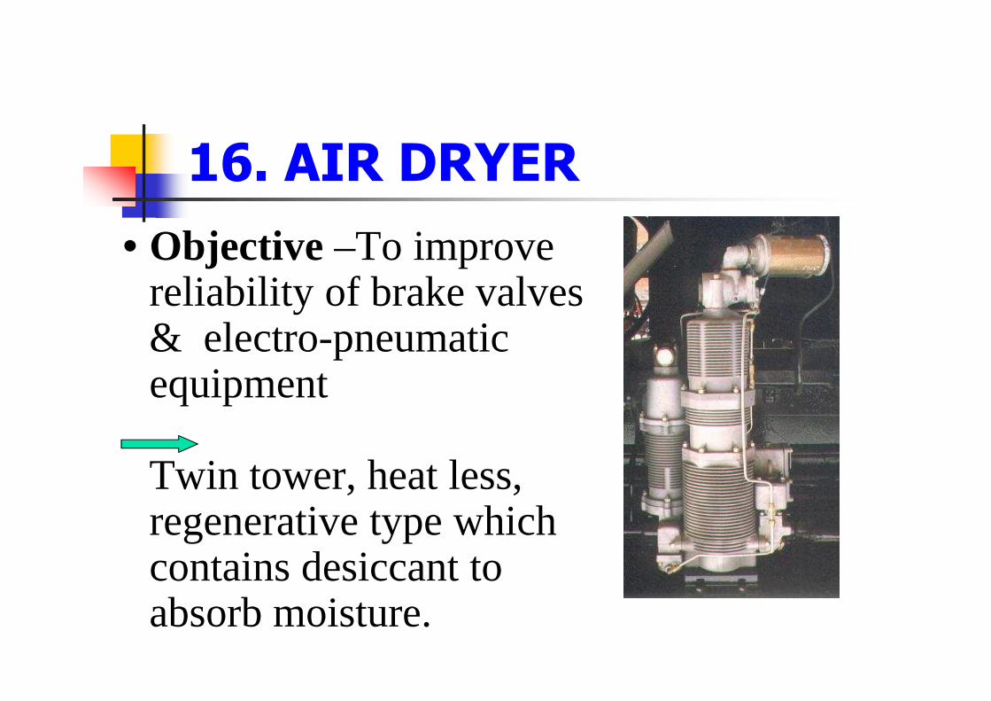
16. AIR DRYER
• Objective –To improve reliability of brake valves & electro-pneumatic equipment
Twin tower, heat less, regenerative type which contains desiccant to absorb moisture.


17. PANEL MOUNTED BRAKE SYSTEM
• Objective – To reduce leakage, To improve trouble shooting and maintenance.
• Initially – rack mounted• Now – panel mounted – (less
pipe joints)• Status – Provided in all pure air
brake locos. Now being developed for dual air brake.

System Improvement
•Microprocessor Control
� E-Type Locomotive Control System utilizescomplex analog circuits based on transistor,magnetic amplifier & electromagnetic / electronicdevices – Problem of reliability.
� Use of Microprocessor System reduces hardware,
eases maintenance, facilitates better (Step lesssmooth) controls & enhances reliability.

Benefits Of Microprocessor Control Systems
� Better management of parasitical loads .Higher input totraction as unused auxiliary power is added - upto 100 hp.
����Higher adhesion – 5-8% more over the existing value.
���� Smooth and continuous /stepless excitation .Reduced
electrical stresses & enhanced life of electrics. Improved WheelSlip Slide Control & enhanced wheel life.
���� Thermal protection of traction machine leading to longer life.
���� Easy trouble shooting due to fault logging, retrieval and selfdiagnostics.
Contd…

Benefits Of Microprocessor Control Systemscontd..
���� Lesser number of electrical interlocks of
relays/contactors, increasing reliability.
���� Improved performance due to elimination of
flash over in power contactors.
���� Flexibility in operation and maintenance due to
user settable parameters.
���� Flexibility for incorporation of new features like
auto flasher, event recording, vigilance controldevice , interface to MCBG , pre lube pump , TELimitation etc.

FEATURES OF µp CONTROL
•Pre Lube: Pre lube for 60 secs prior to Engine starting. Forlubrication of Eng components/ Main Brg. Serially implementedfrom WDG3A 13267 &WDM3D 11126•Post Lubrication: Continues for 5 mins after Eng shut down tolubricate Engine & Turbo. Serially implemented from WDG3A13406 &WDM3D 11241•Self Load: Load heat dissipates through Braking Grids (RoofMounted DBR). Serially implemented from WDG3A 13199&WDM3D 11062•Multi Setting VCD: µp controlled logging of VCD applicationwith warning message and brake application. Seriallyimplemented from WDG3A 13214 & WDM3D 11106.

FEATURES OF µp CONTROL
•TE Limit: Limits the TE upto 30.5 T by limiting max current upto 3000A on weak bridges. µp controls TE current. Serially implemented from WDG3A 13267 onwards.•Event Recorder: Log 20 parameters related to safe operation e.g. BP, VCD cycle etc. Serially implemented from WDG3A 13204 &WDM3D 11125•Auto Flasher: Auto Flasher logic implied through µp. Applied in WDG3A (13024 onwards) & WDM3D 11125 onwards.•Auto Emergency Brake: µp automatically applies AEB when Loco exceeds pre determined speed, specially in ghat section. Applied in all Siemens & Medha µp controlled Locos (need based)

REVISED MAINTENANCE SCHEDULE
� MODIFIED SCHEDULE
- Trip Schedule: 20/ 40 days (T1/T2)
- Monthly Schedule: 60 days (M-2)
- (M-3) Quarterly Schedule: 4 months (M-4)
- (M-9) half yly schedule: 12 months (M-12)
- (M-18) Schedule : 24 months (M-24) with 100% replacement of cylinder liner & piston rings
- (M-36) schedule: 48 months (M-48) * certain critical items of M-36 viz. ABB TSC, EXPR, BRAKES & FTTMB has been reduced to M-24.
- (M-72): same as M-24
- POH to 8 Years (m-96)

ENGINE UPGRADATION
� FIRST PHASE: 2600 TO 3100 HP
WDM2C, WDG2, WDP2
� SECOND PHASE: 3300 HP
WDM3C
� THIRD PHASE: 3600 HP
� WDM3D

3100 HP LOCO
� APPLICATION OF FE KIT
- 17 mm FIP WITH MOD. FP SUPPORT
- STEEL CAP PISTON
- MOD CAM SHAFT WITH 140°VALVE OVERLAP
- HIGH EFFICIENCY AND HIGH CAPACITY TSC WITH LARGER A/ COOLER and MODIFIED WATER CONNECTION
SFC improved from 166.7 to 156 gms/ BHP hr

3300 HP LOCO
� CONSTRAINT FOR UPGRADATION
- REACHING LIMIT OF PEAK FIRING PRESSURE
� MODIFIED INDICATOR DIAGRAM WITH THE CHANGE IN CONFIGURATION
� MODIFIED ENG. SUPPORT SYSTEM

INDICATOR DIAGRAM
Peak firing Pressure
BMEP
Pressure
Volume

3300 HP LOCO CONTD
� Configuration:� Stiffer Unit Cam Shaft with retarded injection (220
BTDC start of injection)
� GE7S176 turbocharger (22.5 sq. inch nozzle) twin discharge
� 11.75 C.R. super bowl steel cap piston
� 251 plus cyl. Head
� H.P fuel tube for 1200 bar pressure rating

3300 HP LOCO CONTD
� Engine support system� Mechanically bonded, louvered fin radiator for 1700 kw heat load
� Twin/single after cooler for 400 kw heat load & >90% effectiveness
� Plate type lube oil cooler for 290-300 kw heat load
� 10” impeller water pump
� Stream lined lube oil and water piping network
� Insulated exhaust manifold

3600 HP CONFIGURATIONCOMPARISON
CONFIGURATION 3300 HP 3600 HP
GE 7S 1716 Turbocharger
22.5 Sq. In. Nozzle 26 Sq. In. Nozzle &Twin Aftercooler
GE Super Bowl Pistons
11.75Compr. ratio 11.75 CompressionRatio
Stiffer Unit Camshaft
Profiled for SharperInjection
Profiled for SharperInjection
17 mm FIP Start of Injection 220
BTDCStart of Injection 220
BTDCNew Injector Nozzles
0.35 mm, 1570
Spray Angle0.40 mm, 1600 SprayAngle
251 Plus Cylinder Head
StrengthenedDouble Deck
Strengthened DoubleDeck

COMPARISON OF PARAMETERSENGINE OPERATING PARAMETERS
3600 HP 3300 HP EXISTING 3100 HP
• Peak Firing Pressure
1870 PSI 1850 PSI 1950 PSI
• Exhaust Gas Temp. 5250C 5090C 5000C
• Boost Pressure 1.95 BAR 1.9 BAR 1.9 BAR
• SFC 8th Notch 153 gm/bhp-hr.
152 gm/bhp-hr.
154 gm/bhp-hr.
• BMEP 17.5 BAR 15.7 BAR 14.7 BAR
• Fuel Injection Pressure
1150 BAR 1150 BAR 950 BAR

COMPARISONPARAMETER 2600 HP 3100 HP 3300 HP 3600 HP
CR 12.5 12.5/ 11.75 11.75 11.75 Peak firing pressure (max. allowed 1950)
1600-1800 psi
1950 psi 1850 psi 1870 psi
BMEP 13.3 bar 14.7 bars 15.7 bars 17.2 bars
Fuel injection pressure
750 bars 950 bars 1150 bar 1150-1200 bars
Injection timing 25 degree btdc
25 degree btdc
22 degree btdc 22 degree btdc
Turbo charger Conv/ Nap/ABB
ABB/NAP GE 7S1716 (22.5 sq. inch nozzle)
GE 7S1716 (26 sq. inch nozzle)
Lube oil cooler 190 KW shell & Tube type
250 kw Plate type, 290-300 kw load
Plate type 500 kw load

CONCLUSIONParameters Before 1990 Year 2000 onwards
SFC (Gm/BHP Hr) 166 154
SFC Litres/1000 GTKM Passenger Service 5.17(95-96) 4.74(2000-2001)
SFC Litres/1000 GTKM Goods Service 3.18 (95-96) 2.74(2000-2001)
HP/Cyl. 160 210/225
Exhaust Gas Temp(degree C) 600 500
Maintenance Schedule 7 days 15/21/30
Equipment Failure (No. /100 loco) 27.3 (95-96) 15.7(99-2000)

Related Documents


