EIO0000000976.00 www.schneider-electric.com Modicon M221 EIO0000000976 02/2020 Modicon M221 Logic Controller User Guide 02/2020

Welcome message from author
This document is posted to help you gain knowledge. Please leave a comment to let me know what you think about it! Share it to your friends and learn new things together.
Transcript

Modicon M221
EIO0000000976 02/2020
EIO
0000
0009
76.0
0
www.schneider-electric.com
Modicon M221Logic ControllerUser Guide02/2020

The information provided in this documentation contains general descriptions and/or technical characteristics of the performance of the products contained herein. This documentation is not intended as a substitute for and is not to be used for determining suitability or reliability of these products for specific user applications. It is the duty of any such user or integrator to perform the appropriate and complete risk analysis, evaluation and testing of the products with respect to the relevant specific application or use thereof. Neither Schneider Electric nor any of its affiliates or subsidiaries shall be responsible or liable for misuse of the information contained herein. If you have any suggestions for improvements or amendments or have found errors in this publication, please notify us. You agree not to reproduce, other than for your own personal, noncommercial use, all or part of this document on any medium whatsoever without permission of Schneider Electric, given in writing. You also agree not to establish any hypertext links to this document or its content. Schneider Electric does not grant any right or license for the personal and noncommercial use of the document or its content, except for a non-exclusive license to consult it on an "as is" basis, at your own risk. All other rights are reserved.All pertinent state, regional, and local safety regulations must be observed when installing and using this product. For reasons of safety and to help ensure compliance with documented system data, only the manufacturer should perform repairs to components.When devices are used for applications with technical safety requirements, the relevant instructions must be followed. Failure to use Schneider Electric software or approved software with our hardware products may result in injury, harm, or improper operating results.Failure to observe this information can result in injury or equipment damage.© 2020 Schneider Electric. All rights reserved.
2 EIO0000000976 02/2020

Table of Contents
Safety Information. . . . . . . . . . . . . . . . . . . . . . . . . . . . . . 15About the Book . . . . . . . . . . . . . . . . . . . . . . . . . . . . . . . . 19
Part I Modicon M221 Logic Controller Programming Part: . 25Chapter 1 About the Modicon M221 Logic Controller . . . . . . . . . . . 27
TM221C Logic Controller Description . . . . . . . . . . . . . . . . . . . . . . . . . 28TM221M Logic Controller Description . . . . . . . . . . . . . . . . . . . . . . . . . 33
Chapter 2 Configuration Features . . . . . . . . . . . . . . . . . . . . . . . . . . 392.1 Objects . . . . . . . . . . . . . . . . . . . . . . . . . . . . . . . . . . . . . . . . . . . . . . . . 40
Objects . . . . . . . . . . . . . . . . . . . . . . . . . . . . . . . . . . . . . . . . . . . . . . . . 41Object Types . . . . . . . . . . . . . . . . . . . . . . . . . . . . . . . . . . . . . . . . . . . . 42Addressing I/O Objects . . . . . . . . . . . . . . . . . . . . . . . . . . . . . . . . . . . . 48Maximum Number of Objects . . . . . . . . . . . . . . . . . . . . . . . . . . . . . . . 52
2.2 Task Structure . . . . . . . . . . . . . . . . . . . . . . . . . . . . . . . . . . . . . . . . . . . 57Tasks and Scan Modes . . . . . . . . . . . . . . . . . . . . . . . . . . . . . . . . . . . . 58Maximum Number of Tasks and Priorities. . . . . . . . . . . . . . . . . . . . . . 61
2.3 Controller States and Behaviors . . . . . . . . . . . . . . . . . . . . . . . . . . . . . 62Controller States Diagram . . . . . . . . . . . . . . . . . . . . . . . . . . . . . . . . . . 63Controller States Description. . . . . . . . . . . . . . . . . . . . . . . . . . . . . . . . 64Controller State Transitions . . . . . . . . . . . . . . . . . . . . . . . . . . . . . . . . . 68Persistent Variables. . . . . . . . . . . . . . . . . . . . . . . . . . . . . . . . . . . . . . . 72Output Behavior. . . . . . . . . . . . . . . . . . . . . . . . . . . . . . . . . . . . . . . . . . 74
2.4 Post Configuration . . . . . . . . . . . . . . . . . . . . . . . . . . . . . . . . . . . . . . . . 78Post Configuration . . . . . . . . . . . . . . . . . . . . . . . . . . . . . . . . . . . . . . . . 79Post Configuration File Management . . . . . . . . . . . . . . . . . . . . . . . . . 81
Chapter 3 Configuring the M221 Logic Controller . . . . . . . . . . . . . . 833.1 How to Configure a Controller . . . . . . . . . . . . . . . . . . . . . . . . . . . . . . . 84
Building a Configuration . . . . . . . . . . . . . . . . . . . . . . . . . . . . . . . . . . . 85Optional I/O Expansion Modules . . . . . . . . . . . . . . . . . . . . . . . . . . . . . 90Configuring the M221 Logic Controller . . . . . . . . . . . . . . . . . . . . . . . . 94Updating Firmware using Executive Loader Wizard . . . . . . . . . . . . . . 95
3.2 Embedded Input/Output Configuration . . . . . . . . . . . . . . . . . . . . . . . . 96Configuring Digital Inputs . . . . . . . . . . . . . . . . . . . . . . . . . . . . . . . . . . 97Configuring Digital Outputs . . . . . . . . . . . . . . . . . . . . . . . . . . . . . . . . . 101Configuring Analog Inputs . . . . . . . . . . . . . . . . . . . . . . . . . . . . . . . . . . 104Configuring High Speed Counters. . . . . . . . . . . . . . . . . . . . . . . . . . . . 106
EIO0000000976 02/2020 3

Configuring Dual Phase and Single Phase Counters . . . . . . . . . . . . . 109Configuring Frequency Meter. . . . . . . . . . . . . . . . . . . . . . . . . . . . . . . . 114Configuring Pulse Generators . . . . . . . . . . . . . . . . . . . . . . . . . . . . . . . 116Configuring Pulse (%PLS) . . . . . . . . . . . . . . . . . . . . . . . . . . . . . . . . . . 118Configuring Pulse Width Modulation (%PWM). . . . . . . . . . . . . . . . . . . 120Configuring Pulse Train Output (%PTO) . . . . . . . . . . . . . . . . . . . . . . . 122Configuring Frequency Generator (%FREQGEN) . . . . . . . . . . . . . . . . 125
3.3 I/O Bus Configuration. . . . . . . . . . . . . . . . . . . . . . . . . . . . . . . . . . . . . . 126I/O Configuration General Description . . . . . . . . . . . . . . . . . . . . . . . . . 127Maximum Hardware Configuration. . . . . . . . . . . . . . . . . . . . . . . . . . . . 131Configuring Cartridges and Expansion Modules . . . . . . . . . . . . . . . . . 135
3.4 Embedded Communication Configuration . . . . . . . . . . . . . . . . . . . . . . 137Configuring Ethernet Network . . . . . . . . . . . . . . . . . . . . . . . . . . . . . . . 138Configuring Modbus TCP. . . . . . . . . . . . . . . . . . . . . . . . . . . . . . . . . . . 146Configuring EtherNet/IP . . . . . . . . . . . . . . . . . . . . . . . . . . . . . . . . . . . . 158Configuring Serial Lines . . . . . . . . . . . . . . . . . . . . . . . . . . . . . . . . . . . . 177Configuring Modbus and ASCII Protocols . . . . . . . . . . . . . . . . . . . . . . 181Configuring the TMH2GDB Remote Graphic Display . . . . . . . . . . . . . 185Configuring Modbus Serial IOScanner. . . . . . . . . . . . . . . . . . . . . . . . . 186Adding a Device on the Modbus Serial IOScanner . . . . . . . . . . . . . . . 187Supported Modbus Function Codes. . . . . . . . . . . . . . . . . . . . . . . . . . . 196
3.5 SD Card . . . . . . . . . . . . . . . . . . . . . . . . . . . . . . . . . . . . . . . . . . . . . . . . 198File Management Operations. . . . . . . . . . . . . . . . . . . . . . . . . . . . . . . . 199SD Card Supported File Types . . . . . . . . . . . . . . . . . . . . . . . . . . . . . . 201Clone Management . . . . . . . . . . . . . . . . . . . . . . . . . . . . . . . . . . . . . . . 203Firmware Management . . . . . . . . . . . . . . . . . . . . . . . . . . . . . . . . . . . . 205Application Management . . . . . . . . . . . . . . . . . . . . . . . . . . . . . . . . . . . 209Post Configuration Management . . . . . . . . . . . . . . . . . . . . . . . . . . . . . 211Error Log Management . . . . . . . . . . . . . . . . . . . . . . . . . . . . . . . . . . . . 213Memory Management: Backing Up and Restoring Controller Memory 216
Chapter 4 Programming the M221 Logic Controller . . . . . . . . . . . . . 2174.1 I/O Objects . . . . . . . . . . . . . . . . . . . . . . . . . . . . . . . . . . . . . . . . . . . . . . 218
Digital Inputs (%I). . . . . . . . . . . . . . . . . . . . . . . . . . . . . . . . . . . . . . . . . 219Digital Outputs (%Q) . . . . . . . . . . . . . . . . . . . . . . . . . . . . . . . . . . . . . . 220Analog Inputs (%IW) . . . . . . . . . . . . . . . . . . . . . . . . . . . . . . . . . . . . . . 221Analog Outputs (%QW) . . . . . . . . . . . . . . . . . . . . . . . . . . . . . . . . . . . . 223
4 EIO0000000976 02/2020

4.2 Network Objects . . . . . . . . . . . . . . . . . . . . . . . . . . . . . . . . . . . . . . . . . 224Input Assembly (EtherNet/IP) Objects (%QWE) . . . . . . . . . . . . . . . . . 225Output Assembly (EtherNet/IP) Objects (%IWE). . . . . . . . . . . . . . . . . 227Input Registers (Modbus TCP) Objects (%QWM) . . . . . . . . . . . . . . . . 228Output Registers (Modbus TCP) Objects (%IWM) . . . . . . . . . . . . . . . 230Digital Input (IOScanner) Objects (%IN) . . . . . . . . . . . . . . . . . . . . . . . 231Digital Output (IOScanner) Objects (%QN) . . . . . . . . . . . . . . . . . . . . . 233Input Register (IOScanner) Objects (%IWN). . . . . . . . . . . . . . . . . . . . 235Output Register (IOScanner) Objects (%QWN) . . . . . . . . . . . . . . . . . 237Modbus IOScanner Network Diagnostic Codes (%IWNS) . . . . . . . . . 239
4.3 System Objects . . . . . . . . . . . . . . . . . . . . . . . . . . . . . . . . . . . . . . . . . . 240System Bits (%S). . . . . . . . . . . . . . . . . . . . . . . . . . . . . . . . . . . . . . . . . 241System Words (%SW). . . . . . . . . . . . . . . . . . . . . . . . . . . . . . . . . . . . . 253Input Channel Status (%IWS) . . . . . . . . . . . . . . . . . . . . . . . . . . . . . . . 278Output Channel Status (%QWS) . . . . . . . . . . . . . . . . . . . . . . . . . . . . . 280
Part II Advanced Functions Library Part . . . . . . . . . . . . . . . 283Chapter 5 Introduction . . . . . . . . . . . . . . . . . . . . . . . . . . . . . . . . . . . 285
Expert I/O . . . . . . . . . . . . . . . . . . . . . . . . . . . . . . . . . . . . . . . . . . . . . . 287Embedded Expert I/O Mapping . . . . . . . . . . . . . . . . . . . . . . . . . . . . . 289General Information on Function Block Management . . . . . . . . . . . . . 292
Chapter 6 Advanced Expert Input Functions. . . . . . . . . . . . . . . . . . 2936.1 Fast Counter (%FC) . . . . . . . . . . . . . . . . . . . . . . . . . . . . . . . . . . . . . . 294
Description. . . . . . . . . . . . . . . . . . . . . . . . . . . . . . . . . . . . . . . . . . . . . . 295Configuration . . . . . . . . . . . . . . . . . . . . . . . . . . . . . . . . . . . . . . . . . . . . 297Programming Example . . . . . . . . . . . . . . . . . . . . . . . . . . . . . . . . . . . . 299
6.2 High Speed Counter (%HSC) . . . . . . . . . . . . . . . . . . . . . . . . . . . . . . . 300Description. . . . . . . . . . . . . . . . . . . . . . . . . . . . . . . . . . . . . . . . . . . . . . 301High Speed Counter in Counting Modes . . . . . . . . . . . . . . . . . . . . . . . 305High Speed Counter in Frequency Meter Mode . . . . . . . . . . . . . . . . . 313
Chapter 7 Advanced Expert Output Functions . . . . . . . . . . . . . . . . 3177.1 Pulse (%PLS) . . . . . . . . . . . . . . . . . . . . . . . . . . . . . . . . . . . . . . . . . . . 318
Description. . . . . . . . . . . . . . . . . . . . . . . . . . . . . . . . . . . . . . . . . . . . . . 319Function Block Configuration. . . . . . . . . . . . . . . . . . . . . . . . . . . . . . . . 321Programming Example . . . . . . . . . . . . . . . . . . . . . . . . . . . . . . . . . . . . 325
7.2 Pulse Width Modulation (%PWM) . . . . . . . . . . . . . . . . . . . . . . . . . . . . 326Description. . . . . . . . . . . . . . . . . . . . . . . . . . . . . . . . . . . . . . . . . . . . . . 327Function Block Configuration. . . . . . . . . . . . . . . . . . . . . . . . . . . . . . . . 329Programming Example . . . . . . . . . . . . . . . . . . . . . . . . . . . . . . . . . . . . 333
EIO0000000976 02/2020 5

7.3 Drive (%DRV). . . . . . . . . . . . . . . . . . . . . . . . . . . . . . . . . . . . . . . . . . . . 334Description . . . . . . . . . . . . . . . . . . . . . . . . . . . . . . . . . . . . . . . . . . . . . . 335Drive and Logic Controller States . . . . . . . . . . . . . . . . . . . . . . . . . . . . 337Adding a Drive Function Block . . . . . . . . . . . . . . . . . . . . . . . . . . . . . . . 339Function Block Configuration . . . . . . . . . . . . . . . . . . . . . . . . . . . . . . . . 341MC_Power_ATV: Enable/Disable Power Stage . . . . . . . . . . . . . . . . . . 342MC_Jog_ATV: Start Jog Mode. . . . . . . . . . . . . . . . . . . . . . . . . . . . . . . 344MC_MoveVel_ATV: Move at Specified Velocity. . . . . . . . . . . . . . . . . . 347MC_Stop_ATV: Stop Movement . . . . . . . . . . . . . . . . . . . . . . . . . . . . . 350MC_ReadStatus_ATV: Read Device Status . . . . . . . . . . . . . . . . . . . . 352MC_ReadMotionState_ATV: Read Motion State . . . . . . . . . . . . . . . . . 355MC_Reset_ATV: Acknowledge and Reset Error . . . . . . . . . . . . . . . . . 358Error Codes . . . . . . . . . . . . . . . . . . . . . . . . . . . . . . . . . . . . . . . . . . . . . 360
7.4 Pulse Train Output (%PTO) . . . . . . . . . . . . . . . . . . . . . . . . . . . . . . . . . 364Pulse Train Output (PTO) . . . . . . . . . . . . . . . . . . . . . . . . . . . . . . . . . . 365Pulse Output Modes. . . . . . . . . . . . . . . . . . . . . . . . . . . . . . . . . . . . . . . 368Acceleration / Deceleration Ramp . . . . . . . . . . . . . . . . . . . . . . . . . . . . 370Probe Event . . . . . . . . . . . . . . . . . . . . . . . . . . . . . . . . . . . . . . . . . . . . . 373Backlash Compensation . . . . . . . . . . . . . . . . . . . . . . . . . . . . . . . . . . . 376Positioning Limits . . . . . . . . . . . . . . . . . . . . . . . . . . . . . . . . . . . . . . . . . 378
7.5 Configuration . . . . . . . . . . . . . . . . . . . . . . . . . . . . . . . . . . . . . . . . . . . . 381PTO Configuration . . . . . . . . . . . . . . . . . . . . . . . . . . . . . . . . . . . . . . . . 382Motion Task Table . . . . . . . . . . . . . . . . . . . . . . . . . . . . . . . . . . . . . . . . 383
7.6 Programming . . . . . . . . . . . . . . . . . . . . . . . . . . . . . . . . . . . . . . . . . . . . 391Adding / Removing a Function Block . . . . . . . . . . . . . . . . . . . . . . . . . . 392PTO Function Blocks . . . . . . . . . . . . . . . . . . . . . . . . . . . . . . . . . . . . . . 394
7.7 Home Modes . . . . . . . . . . . . . . . . . . . . . . . . . . . . . . . . . . . . . . . . . . . . 396Homing Modes . . . . . . . . . . . . . . . . . . . . . . . . . . . . . . . . . . . . . . . . . . . 397Position Setting . . . . . . . . . . . . . . . . . . . . . . . . . . . . . . . . . . . . . . . . . . 400Long Reference . . . . . . . . . . . . . . . . . . . . . . . . . . . . . . . . . . . . . . . . . . 401Short Reference No Reversal . . . . . . . . . . . . . . . . . . . . . . . . . . . . . . . 403Short Reference Reversal . . . . . . . . . . . . . . . . . . . . . . . . . . . . . . . . . . 405Home Offset . . . . . . . . . . . . . . . . . . . . . . . . . . . . . . . . . . . . . . . . . . . . . 407
7.8 Data Parameters . . . . . . . . . . . . . . . . . . . . . . . . . . . . . . . . . . . . . . . . . 408Function Block Object Codes. . . . . . . . . . . . . . . . . . . . . . . . . . . . . . . . 408
7.9 Operation Modes . . . . . . . . . . . . . . . . . . . . . . . . . . . . . . . . . . . . . . . . . 413Motion State Diagram . . . . . . . . . . . . . . . . . . . . . . . . . . . . . . . . . . . . . 414Buffer Mode . . . . . . . . . . . . . . . . . . . . . . . . . . . . . . . . . . . . . . . . . . . . . 416
6 EIO0000000976 02/2020

7.10 Motion Function Blocks . . . . . . . . . . . . . . . . . . . . . . . . . . . . . . . . . . . . 418MC_MotionTask_PTO Function Block . . . . . . . . . . . . . . . . . . . . . . . . 419MC_Power_PTO Function Block . . . . . . . . . . . . . . . . . . . . . . . . . . . . . 423MC_MoveVel_PTO Function Block . . . . . . . . . . . . . . . . . . . . . . . . . . . 426MC_MoveRel_PTO Function Block . . . . . . . . . . . . . . . . . . . . . . . . . . . 431MC_MoveAbs_PTO Function Block . . . . . . . . . . . . . . . . . . . . . . . . . . . 436MC_Home_PTO Function Block . . . . . . . . . . . . . . . . . . . . . . . . . . . . . . 440MC_SetPos_PTO Function Block . . . . . . . . . . . . . . . . . . . . . . . . . . . . 443MC_Stop_PTO Function Block . . . . . . . . . . . . . . . . . . . . . . . . . . . . . . 445MC_Halt_PTO Function Block . . . . . . . . . . . . . . . . . . . . . . . . . . . . . . 448
7.11 Administrative Function Blocks . . . . . . . . . . . . . . . . . . . . . . . . . . . . . . 451MC_ReadActVel_PTO Function Block . . . . . . . . . . . . . . . . . . . . . . . . 452MC_ReadActPos_PTO Function Block . . . . . . . . . . . . . . . . . . . . . . . . 454MC_ReadSts_PTO Function Block . . . . . . . . . . . . . . . . . . . . . . . . . . . 456MC_ReadMotionState_PTO Function Block. . . . . . . . . . . . . . . . . . . 458MC_ReadAxisError_PTO Function Block. . . . . . . . . . . . . . . . . . . . . 460MC_Reset_PTO Function Block . . . . . . . . . . . . . . . . . . . . . . . . . . . . . 462MC_TouchProbe_PTO Function Block . . . . . . . . . . . . . . . . . . . . . . . . 464MC_AbortTrigger_PTO Function Block . . . . . . . . . . . . . . . . . . . . . . 467MC_ReadPar_PTO Function Block . . . . . . . . . . . . . . . . . . . . . . . . . . . 469MC_WritePar_PTO Function Block . . . . . . . . . . . . . . . . . . . . . . . . . . 471
7.12 Frequency Generator (%FREQGEN) . . . . . . . . . . . . . . . . . . . . . . . . . 473Description. . . . . . . . . . . . . . . . . . . . . . . . . . . . . . . . . . . . . . . . . . . . . . 474Configuration . . . . . . . . . . . . . . . . . . . . . . . . . . . . . . . . . . . . . . . . . . . . 476
Chapter 8 PID Function . . . . . . . . . . . . . . . . . . . . . . . . . . . . . . . . . . 4798.1 PID Operating Modes . . . . . . . . . . . . . . . . . . . . . . . . . . . . . . . . . . . . . 480
PID Operating Modes . . . . . . . . . . . . . . . . . . . . . . . . . . . . . . . . . . . . . 4808.2 PID Auto-Tuning Configuration . . . . . . . . . . . . . . . . . . . . . . . . . . . . . . 482
PID Auto-Tuning Configuration . . . . . . . . . . . . . . . . . . . . . . . . . . . . . . 4828.3 PID Standard Configuration. . . . . . . . . . . . . . . . . . . . . . . . . . . . . . . . . 486
PID Word Address Configuration . . . . . . . . . . . . . . . . . . . . . . . . . . . . 487PID Tuning with Auto-Tuning (AT). . . . . . . . . . . . . . . . . . . . . . . . . . . . 490Manual Mode. . . . . . . . . . . . . . . . . . . . . . . . . . . . . . . . . . . . . . . . . . . . 494Determining the Sampling Period (Ts) . . . . . . . . . . . . . . . . . . . . . . . . 496
EIO0000000976 02/2020 7

8.4 PID Assistant . . . . . . . . . . . . . . . . . . . . . . . . . . . . . . . . . . . . . . . . . . . . 499Access the PID Assistant . . . . . . . . . . . . . . . . . . . . . . . . . . . . . . . . . . . 500General Tab . . . . . . . . . . . . . . . . . . . . . . . . . . . . . . . . . . . . . . . . . . . . . 502Input Tab . . . . . . . . . . . . . . . . . . . . . . . . . . . . . . . . . . . . . . . . . . . . . . . 505PID Tab . . . . . . . . . . . . . . . . . . . . . . . . . . . . . . . . . . . . . . . . . . . . . . . . 507AT Tab . . . . . . . . . . . . . . . . . . . . . . . . . . . . . . . . . . . . . . . . . . . . . . . . . 509Output Tab . . . . . . . . . . . . . . . . . . . . . . . . . . . . . . . . . . . . . . . . . . . . . . 511
8.5 PID Programming. . . . . . . . . . . . . . . . . . . . . . . . . . . . . . . . . . . . . . . . . 513Description . . . . . . . . . . . . . . . . . . . . . . . . . . . . . . . . . . . . . . . . . . . . . . 514Programming and Configuring . . . . . . . . . . . . . . . . . . . . . . . . . . . . . . . 516PID States and Detected Error Codes . . . . . . . . . . . . . . . . . . . . . . . . . 517
8.6 PID Parameters . . . . . . . . . . . . . . . . . . . . . . . . . . . . . . . . . . . . . . . . . . 520Role and Influence of PID Parameters. . . . . . . . . . . . . . . . . . . . . . . . . 521PID Parameter Adjustment Method . . . . . . . . . . . . . . . . . . . . . . . . . . . 523
Part III Modicon M221 Logic Controller Hardware Part . . . . 525Chapter 9 M221 General Overview. . . . . . . . . . . . . . . . . . . . . . . . . . 527
9.1 M221 Overview . . . . . . . . . . . . . . . . . . . . . . . . . . . . . . . . . . . . . . . . . . 528TM221C Logic Controller Description . . . . . . . . . . . . . . . . . . . . . . . . . 529TM221M Logic Controller Description . . . . . . . . . . . . . . . . . . . . . . . . . 530Maximum Hardware Configuration. . . . . . . . . . . . . . . . . . . . . . . . . . . . 531TMC2 Cartridges . . . . . . . . . . . . . . . . . . . . . . . . . . . . . . . . . . . . . . . . . 532TM3 Expansion Modules . . . . . . . . . . . . . . . . . . . . . . . . . . . . . . . . . . . 534TM2 Expansion Modules . . . . . . . . . . . . . . . . . . . . . . . . . . . . . . . . . . . 543Accessories . . . . . . . . . . . . . . . . . . . . . . . . . . . . . . . . . . . . . . . . . . . . . 547
9.2 M221 Features . . . . . . . . . . . . . . . . . . . . . . . . . . . . . . . . . . . . . . . . . . . 552Real Time Clock (RTC) . . . . . . . . . . . . . . . . . . . . . . . . . . . . . . . . . . . . 553Input Management . . . . . . . . . . . . . . . . . . . . . . . . . . . . . . . . . . . . . . . . 560Output Management . . . . . . . . . . . . . . . . . . . . . . . . . . . . . . . . . . . . . . 564Run/Stop . . . . . . . . . . . . . . . . . . . . . . . . . . . . . . . . . . . . . . . . . . . . . . . 568SD Card . . . . . . . . . . . . . . . . . . . . . . . . . . . . . . . . . . . . . . . . . . . . . . . 571
9.3 M221 Installation . . . . . . . . . . . . . . . . . . . . . . . . . . . . . . . . . . . . . . . . . 578Environmental Characteristics . . . . . . . . . . . . . . . . . . . . . . . . . . . . . . . 579Certifications and Standards . . . . . . . . . . . . . . . . . . . . . . . . . . . . . . . . 582Installation and Maintenance Requirements . . . . . . . . . . . . . . . . . . . . 583TM221M Logic Controller Mounting Positions and Clearances . . . . . . 586
8 EIO0000000976 02/2020

Top Hat Section Rail (DIN rail) . . . . . . . . . . . . . . . . . . . . . . . . . . . . . . 589TM221C Logic Controller Mounting Positions and Clearances . . . . . . 593Installing and Removing the Controller with Expansions. . . . . . . . . . . 596Direct Mounting on a Panel Surface . . . . . . . . . . . . . . . . . . . . . . . . . . 600
9.4 M221 Electrical Requirements. . . . . . . . . . . . . . . . . . . . . . . . . . . . . . . 602Wiring Best Practices . . . . . . . . . . . . . . . . . . . . . . . . . . . . . . . . . . . . . 603DC Power Supply Characteristics and Wiring . . . . . . . . . . . . . . . . . . . 610AC Power Supply Characteristics and Wiring . . . . . . . . . . . . . . . . . . . 614Grounding the M221 System. . . . . . . . . . . . . . . . . . . . . . . . . . . . . . . . 617
Chapter 10 Modicon TM221C Logic Controller . . . . . . . . . . . . . . . . . 62110.1 Modicon TM221C Logic Controller Presentation. . . . . . . . . . . . . . . . . 622
TM221C16R Presentation . . . . . . . . . . . . . . . . . . . . . . . . . . . . . . . . . . 623TM221CE16R Presentation. . . . . . . . . . . . . . . . . . . . . . . . . . . . . . . . . 628TM221C16T Presentation . . . . . . . . . . . . . . . . . . . . . . . . . . . . . . . . . . 632TM221CE16T Presentation . . . . . . . . . . . . . . . . . . . . . . . . . . . . . . . . . 636TM221C16U Presentation . . . . . . . . . . . . . . . . . . . . . . . . . . . . . . . . . . 640TM221CE16U Presentation. . . . . . . . . . . . . . . . . . . . . . . . . . . . . . . . . 644TM221C24R Presentation . . . . . . . . . . . . . . . . . . . . . . . . . . . . . . . . . . 649TM221CE24R Presentation. . . . . . . . . . . . . . . . . . . . . . . . . . . . . . . . . 653TM221C24T Presentation . . . . . . . . . . . . . . . . . . . . . . . . . . . . . . . . . . 657TM221CE24T Presentation . . . . . . . . . . . . . . . . . . . . . . . . . . . . . . . . . 661TM221C24U Presentation . . . . . . . . . . . . . . . . . . . . . . . . . . . . . . . . . . 665TM221CE24U Presentation. . . . . . . . . . . . . . . . . . . . . . . . . . . . . . . . . 670TM221C40R Presentation . . . . . . . . . . . . . . . . . . . . . . . . . . . . . . . . . . 675TM221CE40R Presentation. . . . . . . . . . . . . . . . . . . . . . . . . . . . . . . . . 680TM221C40T Presentation . . . . . . . . . . . . . . . . . . . . . . . . . . . . . . . . . . 685TM221CE40T Presentation . . . . . . . . . . . . . . . . . . . . . . . . . . . . . . . . . 690TM221C40U Presentation . . . . . . . . . . . . . . . . . . . . . . . . . . . . . . . . . . 695TM221CE40U Presentation. . . . . . . . . . . . . . . . . . . . . . . . . . . . . . . . . 700
10.2 Embedded I/O Channels . . . . . . . . . . . . . . . . . . . . . . . . . . . . . . . . . . . 705Digital Inputs . . . . . . . . . . . . . . . . . . . . . . . . . . . . . . . . . . . . . . . . . . . . 706Relay Outputs . . . . . . . . . . . . . . . . . . . . . . . . . . . . . . . . . . . . . . . . . . . 721Regular and Fast Transistor Outputs . . . . . . . . . . . . . . . . . . . . . . . . . 728Analog Inputs . . . . . . . . . . . . . . . . . . . . . . . . . . . . . . . . . . . . . . . . . . . 738
EIO0000000976 02/2020 9

Chapter 11 Modicon TM221M Logic Controller. . . . . . . . . . . . . . . . . . 74311.1 TM221M16R / TM221M16RG . . . . . . . . . . . . . . . . . . . . . . . . . . . . . . . 744
TM221M16R / TM221M16RG Presentation. . . . . . . . . . . . . . . . . . . . . 745TM221M16R / TM221M16RG Digital Inputs . . . . . . . . . . . . . . . . . . . . 751TM221M16R / TM221M16RG Digital Outputs . . . . . . . . . . . . . . . . . . . 755TM221M16R / TM221M16RG Analog Inputs. . . . . . . . . . . . . . . . . . . . 759
11.2 TM221ME16R / TM221ME16RG . . . . . . . . . . . . . . . . . . . . . . . . . . . . . 763TM221ME16R / TM221ME16RG Presentation . . . . . . . . . . . . . . . . . . 764TM221ME16R / TM221ME16RG Digital Inputs . . . . . . . . . . . . . . . . . . 770TM221ME16R / TM221ME16RG Digital Outputs . . . . . . . . . . . . . . . . 774TM221ME16R / TM221ME16RG Analog Inputs . . . . . . . . . . . . . . . . . 778
11.3 TM221M16T / TM221M16TG. . . . . . . . . . . . . . . . . . . . . . . . . . . . . . . . 782TM221M16T / TM221M16TG Presentation . . . . . . . . . . . . . . . . . . . . . 783TM221M16T / TM221M16TG Digital Inputs. . . . . . . . . . . . . . . . . . . . . 789TM221M16T / TM221M16TG Digital Outputs . . . . . . . . . . . . . . . . . . . 794TM221M16T / TM221M16TG Analog Inputs . . . . . . . . . . . . . . . . . . . . 799
11.4 TM221ME16T / TM221ME16TG . . . . . . . . . . . . . . . . . . . . . . . . . . . . . 803TM221ME16T / TM221ME16TG Presentation. . . . . . . . . . . . . . . . . . . 804TM221ME16T / TM221ME16TG Digital Inputs . . . . . . . . . . . . . . . . . . 810TM221ME16T / TM221ME16TG Digital Outputs . . . . . . . . . . . . . . . . . 815TM221ME16T / TM221ME16TG Analog Inputs. . . . . . . . . . . . . . . . . . 820
11.5 TM221M32TK . . . . . . . . . . . . . . . . . . . . . . . . . . . . . . . . . . . . . . . . . . . 824TM221M32TK Presentation . . . . . . . . . . . . . . . . . . . . . . . . . . . . . . . . . 825TM221M32TK Digital Inputs. . . . . . . . . . . . . . . . . . . . . . . . . . . . . . . . . 830TM221M32TK Digital Outputs . . . . . . . . . . . . . . . . . . . . . . . . . . . . . . . 835TM221M32TK Analog Inputs . . . . . . . . . . . . . . . . . . . . . . . . . . . . . . . . 840
11.6 TM221ME32TK . . . . . . . . . . . . . . . . . . . . . . . . . . . . . . . . . . . . . . . . . . 844TM221ME32TK Presentation. . . . . . . . . . . . . . . . . . . . . . . . . . . . . . . . 845TM221ME32TK Digital Inputs . . . . . . . . . . . . . . . . . . . . . . . . . . . . . . . 850TM221ME32TK Digital Outputs . . . . . . . . . . . . . . . . . . . . . . . . . . . . . . 855TM221ME32TK Analog Inputs . . . . . . . . . . . . . . . . . . . . . . . . . . . . . . . 860
Chapter 12 Modicon M221 Logic Controller Communication . . . . . . . 86512.1 Integrated Communication Ports . . . . . . . . . . . . . . . . . . . . . . . . . . . . . 866
USB Mini-B Programming Port . . . . . . . . . . . . . . . . . . . . . . . . . . . . . . 867Ethernet Port . . . . . . . . . . . . . . . . . . . . . . . . . . . . . . . . . . . . . . . . . . . . 869Serial Line 1 . . . . . . . . . . . . . . . . . . . . . . . . . . . . . . . . . . . . . . . . . . . . 872Serial Line 2 . . . . . . . . . . . . . . . . . . . . . . . . . . . . . . . . . . . . . . . . . . . . . 876
10 EIO0000000976 02/2020

12.2 Connecting the M221 Logic Controller to a PC . . . . . . . . . . . . . . . . . . 879Connecting the Controller to a PC. . . . . . . . . . . . . . . . . . . . . . . . . . . . 879
Part IV Modicon TMH2GDB Remote Graphic Display Part . 883Chapter 13 Presentation . . . . . . . . . . . . . . . . . . . . . . . . . . . . . . . . . . 885
Description. . . . . . . . . . . . . . . . . . . . . . . . . . . . . . . . . . . . . . . . . . . . . . 886Technical Presentation . . . . . . . . . . . . . . . . . . . . . . . . . . . . . . . . . . . . 888Certifications and Standards . . . . . . . . . . . . . . . . . . . . . . . . . . . . . . . . 890Compatibility of The Remote Graphic Display. . . . . . . . . . . . . . . . . . . 891
Chapter 14 Installation. . . . . . . . . . . . . . . . . . . . . . . . . . . . . . . . . . . . 893Installation and Maintenance Requirements . . . . . . . . . . . . . . . . . . . . 894Dimensions and Clearances . . . . . . . . . . . . . . . . . . . . . . . . . . . . . . . . 896Mounting . . . . . . . . . . . . . . . . . . . . . . . . . . . . . . . . . . . . . . . . . . . . . . . 898Connecting the Remote Graphic Display . . . . . . . . . . . . . . . . . . . . . . 903Updating the Firmware . . . . . . . . . . . . . . . . . . . . . . . . . . . . . . . . . . . . 909
Chapter 15 How to Use the Remote Graphic Display . . . . . . . . . . . . 911Description. . . . . . . . . . . . . . . . . . . . . . . . . . . . . . . . . . . . . . . . . . . . . . 912Navigation . . . . . . . . . . . . . . . . . . . . . . . . . . . . . . . . . . . . . . . . . . . . . . 913Password Protection . . . . . . . . . . . . . . . . . . . . . . . . . . . . . . . . . . . . . . 915
Chapter 16 Setup Menu Functionality . . . . . . . . . . . . . . . . . . . . . . . . 917Setup Menu Presentation . . . . . . . . . . . . . . . . . . . . . . . . . . . . . . . . . . 918Controller Setup Menu. . . . . . . . . . . . . . . . . . . . . . . . . . . . . . . . . . . . . 919Controller State Menu . . . . . . . . . . . . . . . . . . . . . . . . . . . . . . . . . . . . . 921Alarm Menu . . . . . . . . . . . . . . . . . . . . . . . . . . . . . . . . . . . . . . . . . . . . . 923Data Table Menu . . . . . . . . . . . . . . . . . . . . . . . . . . . . . . . . . . . . . . . . . 925
Chapter 17 Creating an Operator Interface with EcoStruxure Machine Expert - Basic . . . . . . . . . . . . . . . . . . . . . . . . . . . . . . . . . 929Prerequisite . . . . . . . . . . . . . . . . . . . . . . . . . . . . . . . . . . . . . . . . . . . . . 930EcoStruxure Machine Expert - Basic Display Tab. . . . . . . . . . . . . . . . 932General Properties . . . . . . . . . . . . . . . . . . . . . . . . . . . . . . . . . . . . . . . 934Add/Delete a Page . . . . . . . . . . . . . . . . . . . . . . . . . . . . . . . . . . . . . . . 936Configure a Page. . . . . . . . . . . . . . . . . . . . . . . . . . . . . . . . . . . . . . . . . 945Export/Import a Page. . . . . . . . . . . . . . . . . . . . . . . . . . . . . . . . . . . . . . 948Actions. . . . . . . . . . . . . . . . . . . . . . . . . . . . . . . . . . . . . . . . . . . . . . . . . 949Alarm Definition . . . . . . . . . . . . . . . . . . . . . . . . . . . . . . . . . . . . . . . . . . 952
EIO0000000976 02/2020 11

Part V TMC2 Cartridges Programming Part . . . . . . . . . . . . 953Chapter 18 I/O Configuration General Information . . . . . . . . . . . . . . . 955
I/O Configuration General Practices . . . . . . . . . . . . . . . . . . . . . . . . . . 956General Description . . . . . . . . . . . . . . . . . . . . . . . . . . . . . . . . . . . . . . . 957Using Cartridges in a Configuration . . . . . . . . . . . . . . . . . . . . . . . . . . . 958Configuring Cartridges . . . . . . . . . . . . . . . . . . . . . . . . . . . . . . . . . . . . . 960
Chapter 19 TMC2 Standard Cartridges Configuration . . . . . . . . . . . . 963TMC2AI2 . . . . . . . . . . . . . . . . . . . . . . . . . . . . . . . . . . . . . . . . . . . . . . . 964TMC2TI2 . . . . . . . . . . . . . . . . . . . . . . . . . . . . . . . . . . . . . . . . . . . . . . . 966TMC2AQ2V . . . . . . . . . . . . . . . . . . . . . . . . . . . . . . . . . . . . . . . . . . . . . 969TMC2AQ2C . . . . . . . . . . . . . . . . . . . . . . . . . . . . . . . . . . . . . . . . . . . . . 970TMC2SL1 . . . . . . . . . . . . . . . . . . . . . . . . . . . . . . . . . . . . . . . . . . . . . . 971
Chapter 20 TMC2 Application Cartridges Configuration . . . . . . . . . . . 977TMC2HOIS01. . . . . . . . . . . . . . . . . . . . . . . . . . . . . . . . . . . . . . . . . . . . 978TMC2PACK01 . . . . . . . . . . . . . . . . . . . . . . . . . . . . . . . . . . . . . . . . . . . 980TMC2CONV01 . . . . . . . . . . . . . . . . . . . . . . . . . . . . . . . . . . . . . . . . . . . 982
Chapter 21 TMC2 Analog Cartridge Diagnostics . . . . . . . . . . . . . . . . 987TMC2 Analog Cartridge Diagnostics . . . . . . . . . . . . . . . . . . . . . . . . . . 987
Part VI TMC2 Cartridges Hardware Part . . . . . . . . . . . . . . . 989Chapter 22 TMC2 Cartridges Description . . . . . . . . . . . . . . . . . . . . . 991
General Description . . . . . . . . . . . . . . . . . . . . . . . . . . . . . . . . . . . . . . . 991Chapter 23 TMC2 Cartridges Installation . . . . . . . . . . . . . . . . . . . . . . 993
23.1 TMC2 General Rules for Implementing . . . . . . . . . . . . . . . . . . . . . . . . 994Environmental Characteristics . . . . . . . . . . . . . . . . . . . . . . . . . . . . . . . 995Certifications and Standards . . . . . . . . . . . . . . . . . . . . . . . . . . . . . . . . 996
23.2 TMC2 Installation . . . . . . . . . . . . . . . . . . . . . . . . . . . . . . . . . . . . . . . . . 997Installation and Maintenance Requirements . . . . . . . . . . . . . . . . . . . . 998TMC2 Installation . . . . . . . . . . . . . . . . . . . . . . . . . . . . . . . . . . . . . . . . . 1000
23.3 TMC2 Electrical Requirements . . . . . . . . . . . . . . . . . . . . . . . . . . . . . . 1006Wiring Best Practices . . . . . . . . . . . . . . . . . . . . . . . . . . . . . . . . . . . . . . 1007Grounding the M221 System . . . . . . . . . . . . . . . . . . . . . . . . . . . . . . . . 1010
Chapter 24 TMC2 Standard Cartridges . . . . . . . . . . . . . . . . . . . . . . . 101124.1 TMC2AI2 Analog Voltage, Current Inputs . . . . . . . . . . . . . . . . . . . . . . 1012
TMC2AI2 Presentation. . . . . . . . . . . . . . . . . . . . . . . . . . . . . . . . . . . . . 1013TMC2AI2 Characteristics . . . . . . . . . . . . . . . . . . . . . . . . . . . . . . . . . . . 1014TMC2AI2 Wiring Diagram . . . . . . . . . . . . . . . . . . . . . . . . . . . . . . . . . . 1016
12 EIO0000000976 02/2020

24.2 TMC2TI2 Analog Temperature Inputs . . . . . . . . . . . . . . . . . . . . . . . . . 1017TMC2TI2 Presentation . . . . . . . . . . . . . . . . . . . . . . . . . . . . . . . . . . . . 1018TMC2TI2 Characteristics. . . . . . . . . . . . . . . . . . . . . . . . . . . . . . . . . . . 1019TMC2TI2 Wiring Diagram . . . . . . . . . . . . . . . . . . . . . . . . . . . . . . . . . . 1022
24.3 TMC2AQ2V Analog Voltage Outputs . . . . . . . . . . . . . . . . . . . . . . . . . 1023TMC2AQ2V Presentation . . . . . . . . . . . . . . . . . . . . . . . . . . . . . . . . . . 1024TMC2AQ2V Characteristics . . . . . . . . . . . . . . . . . . . . . . . . . . . . . . . . 1025TMC2AQ2V Wiring Diagram . . . . . . . . . . . . . . . . . . . . . . . . . . . . . . . . 1027
24.4 TMC2AQ2C Analog Current Outputs . . . . . . . . . . . . . . . . . . . . . . . . . 1028TMC2AQ2C Presentation . . . . . . . . . . . . . . . . . . . . . . . . . . . . . . . . . . 1029TMC2AQ2C Characteristics . . . . . . . . . . . . . . . . . . . . . . . . . . . . . . . . 1030TMC2AQ2C Wiring Diagram . . . . . . . . . . . . . . . . . . . . . . . . . . . . . . . . 1032
24.5 TMC2SL1 Serial Line . . . . . . . . . . . . . . . . . . . . . . . . . . . . . . . . . . . . . 1033TMC2SL1 Presentation . . . . . . . . . . . . . . . . . . . . . . . . . . . . . . . . . . . . 1034TMC2SL1 Characteristics . . . . . . . . . . . . . . . . . . . . . . . . . . . . . . . . . . 1035TMC2SL1 Wiring Diagram. . . . . . . . . . . . . . . . . . . . . . . . . . . . . . . . . . 1037
Chapter 25 TMC2 Application Cartridges . . . . . . . . . . . . . . . . . . . . . 103925.1 TMC2HOIS01 Hoisting . . . . . . . . . . . . . . . . . . . . . . . . . . . . . . . . . . . . 1040
TMC2HOIS01 Presentation. . . . . . . . . . . . . . . . . . . . . . . . . . . . . . . . . 1041TMC2HOIS01 Characteristics . . . . . . . . . . . . . . . . . . . . . . . . . . . . . . . 1042TMC2HOIS01 Wiring Diagram . . . . . . . . . . . . . . . . . . . . . . . . . . . . . . 1044
25.2 TMC2PACK01 Packaging . . . . . . . . . . . . . . . . . . . . . . . . . . . . . . . . . . 1045TMC2PACK01 Presentation . . . . . . . . . . . . . . . . . . . . . . . . . . . . . . . . 1046TMC2PACK01 Characteristics . . . . . . . . . . . . . . . . . . . . . . . . . . . . . . 1047TMC2PACK01 Wiring Diagram . . . . . . . . . . . . . . . . . . . . . . . . . . . . . . 1049
25.3 TMC2CONV01 Conveying . . . . . . . . . . . . . . . . . . . . . . . . . . . . . . . . . 1050TMC2CONV01 Presentation . . . . . . . . . . . . . . . . . . . . . . . . . . . . . . . . 1051TMC2CONV01 Characteristics . . . . . . . . . . . . . . . . . . . . . . . . . . . . . . 1052TMC2CONV01 Wiring Diagram. . . . . . . . . . . . . . . . . . . . . . . . . . . . . . 1054
Glossary . . . . . . . . . . . . . . . . . . . . . . . . . . . . . . . . . . . . . . . . . 1055Index . . . . . . . . . . . . . . . . . . . . . . . . . . . . . . . . . . . . . . . . . 1065
EIO0000000976 02/2020 13

14 EIO0000000976 02/2020

Safety Information
Important Information
NOTICERead these instructions carefully, and look at the equipment to become familiar with the device before trying to install, operate, service, or maintain it. The following special messages may appear throughout this documentation or on the equipment to warn of potential hazards or to call attention to information that clarifies or simplifies a procedure.
EIO0000000976 02/2020 15

PLEASE NOTEElectrical equipment should be installed, operated, serviced, and maintained only by qualified personnel. No responsibility is assumed by Schneider Electric for any consequences arising out of the use of this material.A qualified person is one who has skills and knowledge related to the construction and operation of electrical equipment and its installation, and has received safety training to recognize and avoid the hazards involved.
QUALIFICATION OF PERSONNELOnly appropriately trained persons who are familiar with and understand the contents of this manual and all other pertinent product documentation are authorized to work on and with this product. The qualified person must be able to detect possible hazards that may arise from parameterization, modifying parameter values and generally from mechanical, electrical, or electronic equipment. The qualified person must be familiar with the standards, provisions, and regulations for the prevention of industrial accidents, which they must observe when designing and implementing the system.
INTENDED USEThe products described or affected by this document, together with software, accessories, and options, are programmable logic controllers (referred to herein as “logic controllers”), intended for industrial use according to the instructions, directions, examples, and safety information contained in the present document and other supporting documentation.The product may only be used in compliance with all applicable safety regulations and directives, the specified requirements, and the technical data.Prior to using the product, you must perform a risk assessment in view of the planned application. Based on the results, the appropriate safety-related measures must be implemented.Since the product is used as a component in an overall machine or process, you must ensure the safety of persons by means of the design of this overall system.Operate the product only with the specified cables and accessories. Use only genuine accessories and spare parts.Any use other than the use explicitly permitted is prohibited and can result in unanticipated hazards.
16 EIO0000000976 02/2020

BEFORE YOU BEGINDo not use this product on machinery lacking effective point-of-operation guarding. Lack of effective point-of-operation guarding on a machine can result in serious injury to the operator of that machine.
This automation equipment and related software is used to control a variety of industrial processes. The type or model of automation equipment suitable for each application will vary depending on factors such as the control function required, degree of protection required, production methods, unusual conditions, government regulations, etc. In some applications, more than one processor may be required, as when backup redundancy is needed.Only you, the user, machine builder or system integrator can be aware of all the conditions and factors present during setup, operation, and maintenance of the machine and, therefore, can determine the automation equipment and the related safeties and interlocks which can be properly used. When selecting automation and control equipment and related software for a particular application, you should refer to the applicable local and national standards and regulations. The National Safety Council's Accident Prevention Manual (nationally recognized in the United States of America) also provides much useful information.In some applications, such as packaging machinery, additional operator protection such as point-of-operation guarding must be provided. This is necessary if the operator's hands and other parts of the body are free to enter the pinch points or other hazardous areas and serious injury can occur. Software products alone cannot protect an operator from injury. For this reason the software cannot be substituted for or take the place of point-of-operation protection.Ensure that appropriate safeties and mechanical/electrical interlocks related to point-of-operation protection have been installed and are operational before placing the equipment into service. All interlocks and safeties related to point-of-operation protection must be coordinated with the related automation equipment and software programming.NOTE: Coordination of safeties and mechanical/electrical interlocks for point-of-operation protection is outside the scope of the Function Block Library, System User Guide, or other implementation referenced in this documentation.
WARNINGUNGUARDED EQUIPMENT Do not use this software and related automation equipment on equipment which does not have
point-of-operation protection. Do not reach into machinery during operation.Failure to follow these instructions can result in death, serious injury, or equipment damage.
EIO0000000976 02/2020 17

START-UP AND TESTBefore using electrical control and automation equipment for regular operation after installation, the system should be given a start-up test by qualified personnel to verify correct operation of the equipment. It is important that arrangements for such a check be made and that enough time is allowed to perform complete and satisfactory testing.
Follow all start-up tests recommended in the equipment documentation. Store all equipment documentation for future references.Software testing must be done in both simulated and real environments.Verify that the completed system is free from all short circuits and temporary grounds that are not installed according to local regulations (according to the National Electrical Code in the U.S.A, for instance). If high-potential voltage testing is necessary, follow recommendations in equipment documentation to prevent accidental equipment damage.Before energizing equipment: Remove tools, meters, and debris from equipment. Close the equipment enclosure door. Remove all temporary grounds from incoming power lines. Perform all start-up tests recommended by the manufacturer.
OPERATION AND ADJUSTMENTSThe following precautions are from the NEMA Standards Publication ICS 7.1-1995 (English version prevails): Regardless of the care exercised in the design and manufacture of equipment or in the selection
and ratings of components, there are hazards that can be encountered if such equipment is improperly operated.
It is sometimes possible to misadjust the equipment and thus produce unsatisfactory or unsafe operation. Always use the manufacturer’s instructions as a guide for functional adjustments. Personnel who have access to these adjustments should be familiar with the equipment manufacturer’s instructions and the machinery used with the electrical equipment.
Only those operational adjustments actually required by the operator should be accessible to the operator. Access to other controls should be restricted to prevent unauthorized changes in operating characteristics.
WARNINGEQUIPMENT OPERATION HAZARD Verify that all installation and set up procedures have been completed. Before operational tests are performed, remove all blocks or other temporary holding means
used for shipment from all component devices. Remove tools, meters, and debris from equipment.Failure to follow these instructions can result in death, serious injury, or equipment damage.
18 EIO0000000976 02/2020

About the Book
At a Glance
Document Scope Modicon M221 Logic Controller Programming Part:
This part describes the configuration and programming of the Modicon M221 Logic Controller for EcoStruxure Machine Expert - Basic. For further information, refer to the separate documents provided in the EcoStruxure Machine Expert - Basic online help.
Advanced Functions Library Part:This part provides descriptions of the EcoStruxure Machine Expert - Basic advanced functions and their relation to the M221 Logic Controller expert I/O and PID support. Here you can find descriptions of the functionalities, characteristics and performances of the M221 Logic Controller advanced functions.
Modicon M221 Logic Controller Hardware Part:Use this part to: Install and operate your M221 Logic Controller. Connect the M221 Logic Controller to a programming device equipped with EcoStruxure
Machine Expert - Basic software. Interface the M221 Logic Controller with I/O expansion modules, HMI and other devices. Familiarize yourself with the M221 Logic Controller features.
Modicon TMH2GDB Remote Graphic Display Part:Use this part to learn how to: Connect your Remote Graphic Display to your controller. Commission and maintain your Remote Graphic Display. Operate your Remote Graphic Display interface with EcoStruxure Machine Expert - Basic.
TMC2 Cartridges Programming Part:This part describes the software configuration of the TMC2 cartridges for logic controllers supported by EcoStruxure Machine Expert. For further information, refer to the separate documents provided in the EcoStruxure Machine Expert online help.
TMC2 Cartridges Hardware Part:This part describes the hardware implementation of TMC2. It provides the parts description, characteristics, wiring diagrams, and installation details for TMC2.
EIO0000000976 02/2020 19

Validity Note
This document has been updated for the release of EcoStruxureTM Machine Expert - Basic V1.0.The technical characteristics of the devices described in the present document also appear online. To access the information online:
The characteristics that are presented in the present document should be the same as those characteristics that appear online. In line with our policy of constant improvement, we may revise content over time to improve clarity and accuracy. If you see a difference between the document and online information, use the online information as your reference.For product compliance and environmental information (RoHS, REACH, PEP, EOLI, etc.), go to www.schneider-electric.com/green-premium.
Related Documents
Step Action1 Go to the Schneider Electric home page www.schneider-electric.com.2 In the Search box type the reference of a product or the name of a product range.
Do not include blank spaces in the reference or product range. To get information on grouping similar modules, use asterisks (*).
3 If you entered a reference, go to the Product Datasheets search results and click on the reference that interests you.If you entered the name of a product range, go to the Product Ranges search results and click on the product range that interests you.
4 If more than one reference appears in the Products search results, click on the reference that interests you.
5 Depending on the size of your screen, you may need to scroll down to see the data sheet.6 To save or print a data sheet as a .pdf file, click Download XXX product datasheet.
Title of Documentation Reference NumberEcoStruxure Machine Expert - Basic - Operating Guide EIO0000003281 (ENG)
EIO0000003282 (FRA)EIO0000003283 (GER)EIO0000003284 (SPA)EIO0000003285 (ITA)EIO0000003286 (CHS)EIO0000003287 (POR)EIO0000003288 (TUR)
20 EIO0000000976 02/2020

You can download these technical publications and other technical information from our website at https://www.se.com/ww/en/download/ .
Product Related Information
EcoStruxure Machine Expert - Basic Generic Functions - Library Guide
EIO0000003289 (ENG)EIO0000003290 (FRE)EIO0000003291 (GER)EIO0000003292 (SPA)EIO0000003293 (ITA)EIO0000003294 (CHS)EIO0000003295 (POR)EIO0000003296 (TUR)
SR2MOD02 and SR2MOD03 Wireless Modem - User Guide EIO0000001575 (ENG)TM221C DC Logic Controller - Instruction Sheet EAV48550TM221C AC Logic Controller - Instruction Sheet EAV58623TM221M Logic Controller - Instruction Sheet HRB59602
Title of Documentation Reference Number
DANGERHAZARD OF ELECTRIC SHOCK, EXPLOSION OR ARC FLASH Disconnect all power from all equipment including connected devices prior to removing any
covers or doors, or installing or removing any accessories, hardware, cables, or wires except under the specific conditions specified in the appropriate hardware guide for this equipment.
Always use a properly rated voltage sensing device to confirm the power is off where and when indicated.
Replace and secure all covers, accessories, hardware, cables, and wires and confirm that a proper ground connection exists before applying power to the unit.
Use only the specified voltage when operating this equipment and any associated products.Failure to follow these instructions will result in death or serious injury.
EIO0000000976 02/2020 21

1 For additional information, refer to NEMA ICS 1.1 (latest edition), "Safety Guidelines for the Application, Installation, and Maintenance of Solid State Control" and to NEMA ICS 7.1 (latest edition), "Safety Standards for Construction and Guide for Selection, Installation and Operation of Adjustable-Speed Drive Systems" or their equivalent governing your particular location.
DANGERPOTENTIAL FOR EXPLOSION Only use this equipment in non-hazardous locations, or in locations that comply with Class I,
Division 2, Groups A, B, C and D. Do not substitute components which would impair compliance to Class I, Division 2. Do not connect or disconnect equipment unless power has been removed or the location is
known to be non-hazardous. Do not use the USB port(s), if so equipped, unless the location is known to be non-hazardous.Failure to follow these instructions will result in death or serious injury.
WARNINGLOSS OF CONTROL The designer of any control scheme must consider the potential failure modes of control paths
and, for certain critical control functions, provide a means to achieve a safe state during and after a path failure. Examples of critical control functions are emergency stop and overtravel stop, power outage and restart.
Separate or redundant control paths must be provided for critical control functions. System control paths may include communication links. Consideration must be given to the
implications of unanticipated transmission delays or failures of the link. Observe all accident prevention regulations and local safety guidelines.1 Each implementation of this equipment must be individually and thoroughly tested for proper
operation before being placed into service.Failure to follow these instructions can result in death, serious injury, or equipment damage.
WARNINGUNINTENDED EQUIPMENT OPERATION Only use software approved by Schneider Electric for use with this equipment. Update your application program every time you change the physical hardware configuration.Failure to follow these instructions can result in death, serious injury, or equipment damage.
22 EIO0000000976 02/2020

Terminology Derived from StandardsThe technical terms, terminology, symbols and the corresponding descriptions in this manual, or that appear in or on the products themselves, are generally derived from the terms or definitions of international standards.In the area of functional safety systems, drives and general automation, this may include, but is not limited to, terms such as safety, safety function, safe state, fault, fault reset, malfunction, failure, error, error message, dangerous, etc.Among others, these standards include:
Standard DescriptionEN 61131-2:2007 Programmable controllers, part 2: Equipment requirements and tests.ISO 13849-1:2008 Safety of machinery: Safety related parts of control systems.
General principles for design.EN 61496-1:2013 Safety of machinery: Electro-sensitive protective equipment.
Part 1: General requirements and tests.ISO 12100:2010 Safety of machinery - General principles for design - Risk assessment and risk
reductionEN 60204-1:2006 Safety of machinery - Electrical equipment of machines - Part 1: General
requirementsEN 1088:2008ISO 14119:2013
Safety of machinery - Interlocking devices associated with guards - Principles for design and selection
ISO 13850:2006 Safety of machinery - Emergency stop - Principles for designEN/IEC 62061:2005 Safety of machinery - Functional safety of safety-related electrical, electronic,
and electronic programmable control systemsIEC 61508-1:2010 Functional safety of electrical/electronic/programmable electronic safety-
related systems: General requirements.IEC 61508-2:2010 Functional safety of electrical/electronic/programmable electronic safety-
related systems: Requirements for electrical/electronic/programmable electronic safety-related systems.
IEC 61508-3:2010 Functional safety of electrical/electronic/programmable electronic safety-related systems: Software requirements.
IEC 61784-3:2008 Digital data communication for measurement and control: Functional safety field buses.
2006/42/EC Machinery Directive2014/30/EU Electromagnetic Compatibility Directive2014/35/EU Low Voltage Directive
EIO0000000976 02/2020 23

In addition, terms used in the present document may tangentially be used as they are derived from other standards such as:
Finally, the term zone of operation may be used in conjunction with the description of specific hazards, and is defined as it is for a hazard zone or danger zone in the Machinery Directive (2006/42/EC) and ISO 12100:2010.NOTE: The aforementioned standards may or may not apply to the specific products cited in the present documentation. For more information concerning the individual standards applicable to the products described herein, see the characteristics tables for those product references.
Standard DescriptionIEC 60034 series Rotating electrical machinesIEC 61800 series Adjustable speed electrical power drive systemsIEC 61158 series Digital data communications for measurement and control – Fieldbus for use in
industrial control systems
24 EIO0000000976 02/2020

Modicon M221Modicon M221 Logic Controller Programming Part:EIO0000000976 02/2020
Modicon M221 Logic Controller Programming Part:
Part IModicon M221 Logic Controller Programming Part:
OverviewThis part provides general information about the Modicon M221 Logic Controller and its configuration and programming features.
What Is in This Part?This part contains the following chapters:
Chapter Chapter Name Page1 About the Modicon M221 Logic Controller 272 Configuration Features 393 Configuring the M221 Logic Controller 834 Programming the M221 Logic Controller 217
EIO0000000976 02/2020 25

Modicon M221 Logic Controller Programming Part:
26 EIO0000000976 02/2020

Modicon M221About the Modicon M221 Logic ControllerEIO0000000976 02/2020
About the Modicon M221 Logic Controller
Chapter 1About the Modicon M221 Logic Controller
What Is in This Chapter?This chapter contains the following topics:
Topic PageTM221C Logic Controller Description 28TM221M Logic Controller Description 33
EIO0000000976 02/2020 27

About the Modicon M221 Logic Controller
TM221C Logic Controller Description
OverviewThe TM221C Logic Controller has various powerful features and can service a wide range of applications.Software configuration, programming, and commissioning are accomplished with the EcoStruxure Machine Expert - Basic software described in the EcoStruxure Machine Expert - Basic Operating Guide (see EcoStruxure Machine Expert - Basic, Operating Guide) and the M221 Logic Controller - Programming Guide (see page 25).
Programming LanguagesThe M221 Logic Controller is configured and programmed with the EcoStruxure Machine Expert - Basic software, which supports the following IEC 61131-3 programming languages: IL: Instruction List LD: Ladder Diagram Grafcet (List) Grafcet (SFC)
Power SupplyThe power supply of the TM221C Logic Controller is 24 Vdc (see page 610) or 100...240 Vac (see page 614).
Real Time ClockThe M221 Logic Controller includes a Real Time Clock (RTC) system (see page 553).
Run/StopThe M221 Logic Controller can be operated externally by the following: a hardware Run/Stop switch (see page 568) a Run/Stop (see page 568) operation by a dedicated digital input, defined in the software
configuration (for more information, refer to Configuring Digital Inputs (see page 97).) EcoStruxure Machine Expert - Basic software (for more information, refer to Toolbar
(see EcoStruxure Machine Expert - Basic, Operating Guide)). a TMH2GDB Remote Graphic Display (for more information, refer to Controller State Menu
(see page 921)).
28 EIO0000000976 02/2020

About the Modicon M221 Logic Controller
MemoryThis table describes the different types of memory:
Embedded Inputs/OutputsThe following embedded I/O types are available, depending on the controller reference: Regular inputs Fast inputs associated with counters Regular sink/source transistor outputs Fast sink/source transistor outputs associated with pulse generators Relay outputs Analog inputs
Removable StorageThe M221 Logic Controllers include an embedded SD card slot (see page 571).The Modicon M221 Logic Controller allows the following types of file management with an SD card: Clone management (see page 203): back up the application, firmware, and post configuration
(if it exists) of the logic controller Firmware management (see page 205): download firmware to the logic controller, to a
TMH2GDB Remote Graphic Display , or to TM3 expansion modules Application management (see page 209): back up and restore the logic controller application,
or copy it to another logic controller of the same reference Post configuration management (see page 211): add, change, or delete the post configuration
file of the logic controller Error log management (see page 213): back up or delete the error log file of the logic controller Memory management (see page 216): back up and restore memory bits and words from a
controller
Embedded Communication FeaturesThe following types of communication ports are available depending on the controller reference: Ethernet (see page 869) USB Mini-B (see page 867) Serial Line 1 (see page 872)
Memory Type Size Used toRAM 512 Kbytes of RAM memory: 256 Kbytes
for internal variables and 256 Kbytes for application and data.
execute the application and contain data
Non-volatile 1.5 Mbytes, of which 256 Kbytes is used to back up the application and data in case of power outage.
save the application
EIO0000000976 02/2020 29

About the Modicon M221 Logic Controller
Remote Graphic DisplayFor more information, refer to the Modicon TMH2GDB Remote Graphic Display - User Guide.
TM221C Logic Controller
Reference Digital Inputs Digital Outputs Analog Inputs
Communication Ports Power Supply
TM221C16R (see page 623)
5 regular inputs(1)
4 fast inputs (HSC)(2)
7 relay outputs Yes 1 serial line port1 USB programming port
100...240 Vac
TM221CE16R (see page 628)
Yes 1 serial line port1 USB programming port1 Ethernet port
TM221C16T (see page 632)
5 regular inputs(1)
4 fast inputs (HSC)(2)
Source outputs5 regular transistor outputs2 fast outputs (PLS/PWM/PTO/FREQGEN)(3)
Yes 1 serial line port1 USB programming port
24 Vdc
TM221CE16T (see page 636)
Yes 1 serial line port1 USB programming port1 Ethernet port
TM221C16U (see page 640)
5 regular inputs(1)
4 fast inputs (HSC)(2)
Sink outputs5 regular transistor outputs2 fast outputs (PLS/PWM/PTO/FREQGEN)(3)
Yes 1 serial line port1 USB programming port
24 Vdc
TM221CE16U (see page 644)
1 serial line port1 USB programming port1 Ethernet port
NOTE: The TM221C Logic Controller uses removable screw terminal blocks.
(1) The regular inputs have a maximum frequency of 5 kHz.(2) The fast inputs can be used either as regular inputs or as fast inputs for counting or event functions.(3) The fast transistor outputs can be used either as regular transistor outputs, for PLS, PWM, PTO, or FREQGEN
functions, or reflex outputs for HSC.
30 EIO0000000976 02/2020

About the Modicon M221 Logic Controller
TM221C24R (see page 649)
10 regular inputs(1)
4 fast inputs (HSC)(2)
10 relay outputs Yes 1 serial line port1 USB programming port
100...240 Vac
TM221CE24R (see page 653)
Yes 1 serial line port1 USB programming port1 Ethernet port
TM221C24T (see page 657)
Source outputs8 regular transistor outputs2 fast outputs (PLS/PWM/PTO/FREQGEN)(3)
Yes 1 serial line port1 USB programming port
24 Vdc
TM221CE24T (see page 661)
Yes 1 serial line port1 USB programming port1 Ethernet port
TM221C24U (see page 665)
10 regular inputs(1)
4 fast inputs (HSC)(2)
Sink outputs8 regular transistor outputs2 fast outputs (PLS/PWM/PTO/FREQGEN)(3)
Yes 1 serial line port1 USB programming port
24 Vdc
TM221CE24U (see page 670)
Yes 1 serial line port1 USB programming port1 Ethernet port
TM221C40R (see page 675)
20 regular inputs(1)
4 fast inputs (HSC)(2)
16 relay outputs Yes 1 serial line port1 USB programming port
100...240 Vac
TM221CE40R (see page 680)
Yes 1 serial line port1 USB programming port1 Ethernet port
TM221C40T (see page 685)
Source outputs14 regular transistor outputs2 fast outputs (PLS/PWM/PTO/FREQGEN)(3)
Yes 1 serial line port1 USB programming port
24 Vdc
TM221CE40T (see page 690)
Yes 1 serial line port1 USB programming port1 Ethernet port
Reference Digital Inputs Digital Outputs Analog Inputs
Communication Ports Power Supply
NOTE: The TM221C Logic Controller uses removable screw terminal blocks.
(1) The regular inputs have a maximum frequency of 5 kHz.(2) The fast inputs can be used either as regular inputs or as fast inputs for counting or event functions.(3) The fast transistor outputs can be used either as regular transistor outputs, for PLS, PWM, PTO, or FREQGEN
functions, or reflex outputs for HSC.
EIO0000000976 02/2020 31

About the Modicon M221 Logic Controller
Delivery ContentThe following figure presents the content of the delivery for a TM221C Logic Controller:
1 TM221C Logic Controller Instruction Sheet2 TM221C Logic Controller3 Battery holder with lithium carbon monofluoride battery, type Panasonic BR2032.4 Analog cable
TM221C40U (see page 695)
20 regular inputs(1)
4 fast inputs (HSC)(2)
Sink outputs12 regular transistor outputs4 fast outputs (PLS/PWM/PTO/FREQGEN)(3)
Yes 1 serial line port1 USB programming port
24 Vdc
TM221CE40U (see page 700)
Yes 1 serial line port1 USB programming port1 Ethernet port
Reference Digital Inputs Digital Outputs Analog Inputs
Communication Ports Power Supply
NOTE: The TM221C Logic Controller uses removable screw terminal blocks.
(1) The regular inputs have a maximum frequency of 5 kHz.(2) The fast inputs can be used either as regular inputs or as fast inputs for counting or event functions.(3) The fast transistor outputs can be used either as regular transistor outputs, for PLS, PWM, PTO, or FREQGEN
functions, or reflex outputs for HSC.
32 EIO0000000976 02/2020

About the Modicon M221 Logic Controller
TM221M Logic Controller Description
OverviewThe TM221M Logic Controller has various powerful features and can service a wide range of applications.Software configuration, programming, and commissioning are accomplished with the EcoStruxure Machine Expert - Basic software described in the EcoStruxure Machine Expert - Basic Operating Guide (see EcoStruxure Machine Expert - Basic, Operating Guide) and the M221 Logic Controller - Programming Guide (see page 25).
Programming LanguagesThe M221 Logic Controller is configured and programmed with the EcoStruxure Machine Expert - Basic software, which supports the following IEC 61131-3 programming languages: IL: Instruction List LD: Ladder Diagram Grafcet (List) Grafcet (SFC)
Power SupplyThe power supply of the TM221M Logic Controller is 24 Vdc (see page 610).
Real Time ClockThe M221 Logic Controller includes a Real Time Clock (RTC) system (see page 553).
Run/StopThe M221 Logic Controller can be operated externally by the following: a hardware Run/Stop switch (see page 568) a Run/Stop (see page 568) operation by a dedicated digital input, defined in the software
configuration (for more information, refer to Configuring Digital Inputs (see page 97)) EcoStruxure Machine Expert - Basic software (for more information, refer to Toolbar
(see EcoStruxure Machine Expert - Basic, Operating Guide)). a TMH2GDB Remote Graphic Display (for more information, refer to Controller State Menu
(see page 921)).
EIO0000000976 02/2020 33

About the Modicon M221 Logic Controller
MemoryThis table describes the different types of memory:
Embedded Inputs/OutputsThe following embedded I/O types are available, depending on the controller reference: Regular inputs Fast inputs (HSC) Regular transistor outputs Fast transistor outputs (PLS/PWM/PTO/FREQGEN) Relay outputs Analog inputs
Removable StorageThe M221 Logic Controllers include an embedded SD card slot (see page 571).The Modicon M221 Logic Controller allows the following types of file management with an SD card: Clone management (see page 203): back up the application, firmware, and post configuration
(if it exists) of the logic controller Firmware management (see page 205): download firmware updates directly to the logic
controller, and download firmware to a TMH2GDB Remote Graphic Display Application management (see page 209): back up and restore the logic controller application,
or copy it to another logic controller of the same reference Post configuration management (see page 211): add, change, or delete the post configuration
file of the logic controller Error log management (see page 213): back up or delete the error log file of the logic controller Memory management (see page 216): backup/restore of memory bits and words from a
controller
Memory Type Size Used toRAM 512 Kbytes of RAM memory: 256 Kbytes
for internal variables and 256 Kbytes for application and data.
execute the application and contains data
Non-volatile 1.5 Mbytes, of which 256 Kbytes is used to back up the application and data in case of power outage.
save the application
34 EIO0000000976 02/2020

About the Modicon M221 Logic Controller
Embedded Communication FeaturesThe following communication ports are available on the front panel of the controller, depending on the controller reference: Ethernet (see page 869) USB Mini-B (see page 867) SD Card (see page 571) Serial Line 1 (see page 872) Serial Line 2 (see page 876)
Remote Graphic DisplayFor more information, refer to the Modicon TMH2GDB Remote Graphic Display - User Guide.
TM221M Logic Controller
Reference Digital Input Digital Output Analog Input
Communication Ports
Terminal Type
TM221M16R (see page 744)
4 regular inputs(1)
4 fast inputs (HSC)(2)
8 relay outputs Yes 2 serial line ports1 USB programming port
Removable screw terminal blocks
TM221M16RG (see page 744)
4 regular inputs(1)
4 fast inputs (HSC)(2)
8 relay outputs Yes 2 serial line ports1 USB programming port
Removable spring terminal blocks
TM221ME16R (see page 763)
4 regular inputs(1)
4 fast inputs (HSC)(2)
8 relay outputs Yes 1 serial line port1 USB programming port1 Ethernet port
Removable screw terminal blocks
TM221ME16RG (see page 763)
4 regular inputs(1)
4 fast inputs (HSC)(2)
8 relay outputs Yes 1 serial line port1 USB programming port1 Ethernet port
Removable spring terminal blocks
TM221M16T (see page 782)
4 regular inputs(1)
4 fast inputs (HSC)(2)
6 regular transistor outputs2 fast transistor outputs (PLS/PWM/PTO/FREQGEN)(3)
Yes 2 serial line ports1 USB programming port
Removable screw terminal blocks
NOTE: The TM221M Logic Controller uses a 24 Vdc power supply (see page 610).(1) The regular inputs I2, I3, I4, and I5 have a maximum frequency of 5 kHz.
The other regular inputs have a maximum frequency of 100 Hz.(2) The fast inputs can be used either as regular inputs or as fast inputs for counting or event functions.(3) The fast transistor outputs can be used as regular transistor outputs, for PLS, PWM, PTO or FREQGEN functions,
or reflex outputs for HSC.
EIO0000000976 02/2020 35

About the Modicon M221 Logic Controller
TM221M16TG (see page 782)
4 regular inputs(1)
4 fast inputs (HSC)(2)
6 regular transistor outputs2 fast transistor outputs (PLS/PWM/PTO/FREQGEN)(3)
Yes 2 serial line ports1 USB programming port
Removable spring terminal blocks
TM221ME16T (see page 803)
4 regular inputs(1)
4 fast inputs (HSC)(2)
6 regular transistor outputs2 fast transistor outputs (PLS/PWM/PTO/FREQGEN)(3)
Yes 1 serial line port1 USB programming port1 Ethernet port
Removable screw terminal blocks
TM221ME16TG (see page 803)
4 regular inputs(1)
4 fast inputs (HSC)(2)
6 regular transistor outputs2 fast transistor outputs (PLS/PWM/PTO/FREQGEN)(3)
Yes 1 serial line portUSB programming port1 Ethernet port
Removable spring terminal blocks
TM221M32TK (see page 824)
12 regular inputs(1)
4 fast inputs (HSC)(2)
14 regular transistor outputs2 fast outputs (PLS/PWM/PTO/FREQGEN)(3)
Yes 2 serial line ports1 USB programming port
HE10 (MIL20) connectors
TM221ME32TK (see page 824)
12 regular inputs(1)
4 fast inputs (HSC)(2)
14 regular outputs2 fast outputs (PLS/PWM/PTO/FREQGEN)(3)
Yes 1 serial line port1 USB programming port1 Ethernet port
HE10 (MIL 20) connectors
Reference Digital Input Digital Output Analog Input
Communication Ports
Terminal Type
NOTE: The TM221M Logic Controller uses a 24 Vdc power supply (see page 610).(1) The regular inputs I2, I3, I4, and I5 have a maximum frequency of 5 kHz.
The other regular inputs have a maximum frequency of 100 Hz.(2) The fast inputs can be used either as regular inputs or as fast inputs for counting or event functions.(3) The fast transistor outputs can be used as regular transistor outputs, for PLS, PWM, PTO or FREQGEN functions,
or reflex outputs for HSC.
36 EIO0000000976 02/2020

About the Modicon M221 Logic Controller
Delivery ContentThe following figure presents the content of the delivery for a TM221M Logic Controller:
1 TM221M Logic Controller Instruction Sheet2 TM221M Logic Controller3 Battery holder with lithium carbon monofluoride battery, type Panasonic BR2032.4 Analog cable
EIO0000000976 02/2020 37

About the Modicon M221 Logic Controller
38 EIO0000000976 02/2020

Modicon M221Configuration FeaturesEIO0000000976 02/2020
Configuration Features
Chapter 2Configuration Features
IntroductionThis chapter provides information related to M221 Logic Controller memory mapping, task, states, behaviors, objects, and functions. The topics explained in this chapter allow the operator to understand the featured specifications of M221 Logic Controller that are primarily needed to configure and program the controller in EcoStruxure Machine Expert - Basic.
What Is in This Chapter?This chapter contains the following sections:
Section Topic Page2.1 Objects 402.2 Task Structure 572.3 Controller States and Behaviors 622.4 Post Configuration 78
EIO0000000976 02/2020 39

Configuration Features
Objects
Section 2.1Objects
What Is in This Section?This section contains the following topics:
Topic PageObjects 41Object Types 42Addressing I/O Objects 48Maximum Number of Objects 52
40 EIO0000000976 02/2020

Configuration Features
Objects
OverviewIn EcoStruxure Machine Expert - Basic, the term object is used to represent an area of logic controller memory reserved for use by an application. Objects can be: Simple software variables, such as memory bits and words Addresses of digital or analog inputs and outputs Controller-internal variables, such as system words and system bits Predefined system functions or function blocks, such as timers and counters.Controller memory is either pre-allocated for certain object types, or automatically allocated when an application is downloaded to the logic controller.Objects can only be addressed by a program once memory has been allocated. Objects are addressed using the prefix %. For example, %MW12 is the address of a memory word, %Q0.3 is the address of an embedded digital output, and %TM0 is the address of a Timer function block.
EIO0000000976 02/2020 41

Configuration Features
Object Types
IntroductionThe language object types for the M221 Logic Controller are described in the following table:
Object Type Object Object Function DescriptionMemory objects %M Memory bits
(see EcoStruxure Machine Expert - Basic, Generic Functions Library Guide)
Stores memory bit.
%MW Memory words (see EcoStruxure Machine Expert - Basic, Generic Functions Library Guide)
Stores 16-bit memory word.
%MD Memory double words (see EcoStruxure Machine Expert - Basic, Generic Functions Library Guide)
Stores 32-bit memory word.
%MF Memory floating point (see EcoStruxure Machine Expert - Basic, Generic Functions Library Guide)
Stores memory floating point in a mathematical argument which has a decimal in its expression.
%KW Constant words (see EcoStruxure Machine Expert - Basic, Generic Functions Library Guide)
Stores 16-bit constant word.
%KD Constant double words (see EcoStruxure Machine Expert - Basic, Generic Functions Library Guide)
Stores 32-bit constant word.
%KF Constant floating points (see EcoStruxure Machine Expert - Basic, Generic Functions Library Guide)
Stores constant floating point in a mathematical argument which has a decimal in its expression.
System objects %S System bits (see page 241)
Stores system bit.
%SW System words (see page 253)
Stores system word.
%IWS Input channel status word (see page 278)
Contains diagnostic information concerning analog input channels.
%QWS Output channel status word (see page 280)
Contains diagnostic information concerning analog output channels.
42 EIO0000000976 02/2020

Configuration Features
I/O objects %I Input bits (see page 219) Stores value of the digital input.%Q Output bits (see page 220) Stores value of the digital output.%IW Input words
(see page 221)Stores value of the analog input.
%QW Output words (see page 223)
Stores value of the analog output.
%FC Fast counters (see page 294)
Execute fast counts of pulses from sensors, switches, and so on.
%HSC High speed counters (see page 300)
Execute fast counts of pulses from sensors, switches, and so on, that are connected to the fast inputs.
%PLS Pulse (see page 318) Generates a square wave pulse signal on dedicated output channels.
%PWM Pulse width modulation (see page 326)
Generates a modulated wave signal on dedicated output channels with a variable duty cycle.
%PTO Pulse train output (see page 364)
Generates a pulse train output to control a linear single-axis stepper or servo drive in open loop mode.
%FREQGEN Frequency Generator (see page 473)
Generates a square wave signal on a dedicated output channel with programmable frequency and duty cycle of 50%.
Object Type Object Object Function Description
EIO0000000976 02/2020 43

Configuration Features
Network objects %QWE Input assembly (EtherNet/IP) (see page 225)
The values of EtherNet/IP Input assembly frames sent by the logic controller.
NOTE: For more details about directionality, refer to Configuring EtherNet/IP (see page 159).
%IWE Output assembly (EtherNet/IP) (see page 227)
The values of EtherNet/IP Output assembly frames received by the logic controller.
NOTE: For more details about directionality, refer to Configuring EtherNet/IP (see page 159).
%QWM Input registers (Modbus TCP) (see page 228)
The values of Modbus mapping table Input registers sent by the logic controller.
%IWM Output registers (Modbus TCP) (see page 230)
The values of Modbus mapping table Output registers received by the logic controller.
%IN Digital inputs (IOScanner) (see page 231)
The values of Modbus Serial or TCP IOScanner digital input bits.
%QN Digital outputs (IOScanner) (see page 233)
The values of Modbus Serial or TCP IOScanner digital output bits.
%IWN Input registers (IOScanner) (see page 235)
The values of Modbus Serial or TCP IOScanner digital input words.
%QWN Output registers (IOScanner) (see page 237)
The values of Modbus Serial or TCP IOScanner digital output words.
%IWNS IOScanner network diagnostic codes (see page 239)
The values of Modbus Serial or TCP IOScanner network diagnostic bits.
Object Type Object Object Function Description
44 EIO0000000976 02/2020

Configuration Features
Software objects %TM Timers (see EcoStruxure Machine Expert - Basic, Generic Functions Library Guide)
Specifies a time before triggering an action.
%C Counters (see EcoStruxure Machine Expert - Basic, Generic Functions Library Guide)
Provides up and down counting of actions.
%MSG Messages (see EcoStruxure Machine Expert - Basic, Generic Functions Library Guide)
Stores the status message at the communication port.
%R LIFO/FIFO registers (see EcoStruxure Machine Expert - Basic, Generic Functions Library Guide)
Stores memory up to 16 words of16 bits each in 2 different ways, queue, and stacks.
%DR Drums (see EcoStruxure Machine Expert - Basic, Generic Functions Library Guide)
Operates on a principle similar to an electromechanical drum controller which changes step according to external events.
%SBR Shift bit registers (see EcoStruxure Machine Expert - Basic, Generic Functions Library Guide)
Provides a left or right shift of binary data bits (0 or 1).
%SC Step counters (see EcoStruxure Machine Expert - Basic, Generic Functions Library Guide)
Provides a series of steps to which actions can be assigned.
SCH Schedule blocks (see EcoStruxure Machine Expert - Basic, Generic Functions Library Guide)
Controls actions at a predefined month, day, and time.
%RTC RTC (see EcoStruxure Machine Expert - Basic, Generic Functions Library Guide)
Allows reading or writing the value of the Real Time Clock (RTC) on the logic controller.
PID PID (see page 513) Provides a generic control loop feedback in which output is proportional, integral, and derivative of the input.
%X Grafcet steps (see EcoStruxure Machine Expert - Basic, Generic Functions Library Guide)
Bit objects associated with individual Grafcet (SFC) steps. Object is set to 1 when the corresponding step is active, and set to 0 when the step is deactivated.
Object Type Object Object Function Description
EIO0000000976 02/2020 45

Configuration Features
Object Type Object Object Function DescriptionPTO objects Refer to Pulse Train Output (see page 364).Drive objects Refer to Drive Objects (see page 334).Communication objects
%READ_VAR Read Var (see EcoStruxure Machine Expert - Basic, Generic Functions Library Guide)
The %READ_VAR function block is used to read data from a remote device on Modbus SL or Modbus TCP.
%WRITE_VAR Write Var (see EcoStruxure Machine Expert - Basic, Generic Functions Library Guide)
The %WRITE_VAR function block is used to write data to an external device using the Modbus SL or Modbus TCP protocol.
%WRITE_READ_VAR Write Read Var (see EcoStruxure Machine Expert - Basic, Generic Functions Library Guide)
The %WRITE_READ_VAR function block is used to read and write data stored in internal memory words to an external device using the Modbus SL or Modbus TCP protocol.
%SEND_RECV_MSG Send Receive Message (see EcoStruxure Machine Expert - Basic, Generic Functions Library Guide)
The %SEND_RECV_MSG function block is used to send or receive data on a serial line configured for the ASCII protocol.
%SEND_RECV_SMS Send Receive SMS (see EcoStruxure Machine Expert - Basic, Generic Functions Library Guide)
The %SEND_RECV_SMS function block is used to send or receive SMS messages through a GSM modem connected to a serial line.
46 EIO0000000976 02/2020

Configuration Features
Memory objects and software objects are generic objects used in EcoStruxure Machine Expert - Basic, whereas system objects and I/O objects are controller-specific. All controller-specific objects are discussed in the Programming (see page 217) section.For programming details of memory objects, software objects, and communication objects, refer to the EcoStruxure Machine Expert - Basic Generic Functions Library Guide.For programming details of PID, Drive, and PTO objects, refer to the Advanced Functions Library Guide.For more information on user-defined functions and user-defined function blocks, refer to EcoStruxure Machine Expert - Basic Operating Guide (see EcoStruxure Machine Expert - Basic, Operating Guide).
User-defined function and user-defined function block objects
%RET0 Return value (see EcoStruxure Machine Expert - Basic, Operating Guide)
The return value of a user-defined function.
%PARAM Parameter (see EcoStruxure Machine Expert - Basic, Operating Guide)
Parameters of a user-defined function or user-defined function block.The parameters are different for each object type.
%VAR Local variable (see EcoStruxure Machine Expert - Basic, Operating Guide)
Local variables of a user-defined function or user-defined function block.The local variables are different for each object type.
Object Type Object Object Function Description
EIO0000000976 02/2020 47

Configuration Features
Addressing I/O Objects
Addressing ExamplesThis table presents addressing examples for various object types:
Object Type Syntax Example DescriptionMemory objectsMemory bits %Mi %M25 Internal memory bit 25.Memory words %MWi %MW15 Internal memory word 15.Memory double words %MDi %MD16 Internal memory double word 16.Memory floating points %MFi %MF17 Internal memory floating point 17.Constant words %KWi %KW26 Constant word 26.Constant double words %KDi %KD27 Internal constant double word 27.Constant floating points %KFi %KF28 Internal constant floating point
28.System objectsSystem bits %Si %S8 System bit 8.System words %SWi %SW30 System word 30.I/O objectsDigital inputs %Iy.z %I0.5 Digital input 5 on the controller
(embedded I/O).Digital outputs %Qy.z %Q3.4 Digital output 4 on the expansion
module at address 3 (expansion module I/O).
Analog inputs %IWy.z %IW0.1 Analog input 1 on the controller (embedded I/O).
Analog outputs %QW0.m0n %QW0.100 Analog output 0 on the cartridge 1.
Fast counters %FCi %FC2 Fast counter 2 on the controller.High speed counters %HSCi %HSC1 High speed counter 1 on the
controller.Pulse %PLSi %PLS0 Pulse output 0 on the controller.a 100 + device number on SL1, 200 + device number on SL2, 300 + device number on ETH1.b Channel number of the Modbus Serial IOScanner or Modbus TCP IOScanner device.c Object instance identifer in the channel.i Object instance identifier that indicates the instance of the object on the controller.m Cartridge number on the controller.n Channel number on the cartridge.y Indicates the I/O type. It is 0 for the controller and 1, 2, and so on, for the expansion modules.z Channel number on the controller or expansion module.
48 EIO0000000976 02/2020

Configuration Features
Pulse width modulation %PWMi %PWM1 Pulse width modulation output 1 on the controller.
Pulse train output %PTOi %PTO1 Pulse train output 1 on the controller.
Frequency generator %FREQGENi %FREQGEN1 Frequency generator 1 on the controller.
Network objectsInput assembly (EtherNet/IP)
%QWEi %QWE8 Input assembly instance 8.
Output assembly (EtherNet/IP)
%IWEi %IWE6 Output assembly instance 6.
Input registers (Modbus TCP)
%QWMi %QWM1 Input register instance 1.
Output registers (Modbus TCP)
%IWMi %IWM0 Output register instance 0.
Digital inputs (IOScanner)
%INa.b.c %IN300.2.1 Modbus TCP IOScanner slave device 0 on ETH1, channel 2, digital input 1.
Digital outputs (IOScanner)
%QNa.b.c %QN101.1.0 Modbus Serial IOScanner slave device 1 on SL1, channel 1, digital output 0.
Input registers (IOScanner)
%IWNa.b.c %IWN302.3.0 Modbus TCP IOScanner slave device 2 on ETH1, channel 3, input register 0.
Output registers (IOScanner)
%QWNa.b.c %QWN205.0.4 Modbus Serial IOScanner slave device 5 on SL2, channel 0, output register 4.
IOScanner network diagnostic codes
%IWNSa %IWNS302 Status of Modbus TCP IOScanner slave device 2 on ETH1.
%IWNSa.b %IWNS205.3 Status of channel 3 of Modbus Serial IOScanner slave device 5 on serial line SL2
Object Type Syntax Example Description
a 100 + device number on SL1, 200 + device number on SL2, 300 + device number on ETH1.b Channel number of the Modbus Serial IOScanner or Modbus TCP IOScanner device.c Object instance identifer in the channel.i Object instance identifier that indicates the instance of the object on the controller.m Cartridge number on the controller.n Channel number on the cartridge.y Indicates the I/O type. It is 0 for the controller and 1, 2, and so on, for the expansion modules.z Channel number on the controller or expansion module.
EIO0000000976 02/2020 49

Configuration Features
Software objectsTimers %TMi %TM5 Timer instance 5.Counters %Ci %C2 Counter instance 2.Message %MSGi %MSG1 Program compilation status
message 1.LIFO/FIFO registers %Ri %R3 FIFO/LIFO registers instance 3.Drums %DRi %DR6 Drum register 6 on the controller.Shift bit registers %SBRi %SBR5 Shift bit register 5 on the
controller.Step counters %SCi %SC5 Step counter 5 on the controller.Schedule blocks SCH i SCH 3 Schedule block 3 on the
controller.RTC RTCi RTC 1 Real-time clock (RTC) instance
1.PID PID i PID 7 PID feedback object 7 on the
controller.Grafcet Steps Xi X1 Grafcet step 1.PTO objectsMC_Power_PTO (motion function block)
%MC_POWER_PTOi %MC_POWER_PTO1 MC_POWER_PTO function block instance 1.
MC_Reset_PTO (administrative function block)
%MC_RESET_PTOi %MC_RESET_PTO0 MC_RESET_PTO function block instance 0.
Object Type Syntax Example Description
a 100 + device number on SL1, 200 + device number on SL2, 300 + device number on ETH1.b Channel number of the Modbus Serial IOScanner or Modbus TCP IOScanner device.c Object instance identifer in the channel.i Object instance identifier that indicates the instance of the object on the controller.m Cartridge number on the controller.n Channel number on the cartridge.y Indicates the I/O type. It is 0 for the controller and 1, 2, and so on, for the expansion modules.z Channel number on the controller or expansion module.
50 EIO0000000976 02/2020

Configuration Features
Communication objectsRead Var %READ_VARi %READ_VAR2 READ_VAR function block
instance 2.Write Var %WRITE_VARi %WRITE_VAR4 WRITE_VAR function block
instance 4.Write Read Var %WRITE_READ_VARi %WRITE_READ_VAR0 WRITE_READ_VAR function
block instance 0.Send Receive Message %SEND_RECV_MSGi %SEND_RECV_MSG6 SEND_RECV_MSG function block
instance 6.Send Receive SMS %SEND_RECV_SMSi %SEND_RECV_SMS0 SEND_RECV_SMS function block
instance 0.User-defined function and user-defined function block objectsReturn value %RETi %RET0 Return value of a user-defined
function.Parameters %PARAMi %PARAM0 Parameter of a user-defined
function.Local variables %VARi %VAR0 Local variables of a user-defined
function.
Object Type Syntax Example Description
a 100 + device number on SL1, 200 + device number on SL2, 300 + device number on ETH1.b Channel number of the Modbus Serial IOScanner or Modbus TCP IOScanner device.c Object instance identifer in the channel.i Object instance identifier that indicates the instance of the object on the controller.m Cartridge number on the controller.n Channel number on the cartridge.y Indicates the I/O type. It is 0 for the controller and 1, 2, and so on, for the expansion modules.z Channel number on the controller or expansion module.
EIO0000000976 02/2020 51

Configuration Features
Maximum Number of Objects
Maximum Number of Objects DescriptionThis table provides information about the maximum number of objects supported by the M221 Logic Controller:
Objects M221 Logic Controller ReferencesModular References Compact ReferencesTM221M16R•TM221ME16R•
TM221M16T•TM221ME16T•TM221M32TKTM221ME32TK
TM221C••RTM221CE••R
TM221C••TTM221CE••TTM221C••UTM221CE••U
Memory objects
%M(1) 5121024
5121024
5121024
5121024
%MW 8000 8000 8000 8000%MD%MF
7999 7999 7999 7999
%KW 512 512 512 512%KD%KF
511 511 511 511
System objects%S 160 160 160 160%SW 234 234 234 234%IWS 1 created automatically for each analog input%QWS 1 created automatically for each analog outputI/O objects%I 8 8
(for TM221M16T• and TM221ME16T•)
9(for TM221C16• and TM221CE16•)
9(for TM221C16• and TM221CE16•)
16(for TM221M32TK and TM221ME32TK)
14(for TM221C24• and TM221CE24•)
14(for TM221C24• and TM221CE24•)
24(for TM221C40• and TM221CE40•)
24(for TM221C40• and TM221CE40•)
(1) The value 512 is for software version < 1.3.(2) If functional level < 6.0. If functional level >= 6.0, the maximum number of objects is 512.
52 EIO0000000976 02/2020

Configuration Features
%Q 8 8(for TM221M16T• and TM221ME16T•)
7(for TM221C16• and TM221CE16•)
7(for TM221C16• and TM221CE16•)
16(for TM221M32TK and TM221ME32TK)
10(for TM221C24• and TM221CE24•)
10(for TM221C24• and TM221CE24•)
16(for TM221C40• and TM221CE40•)
16(for TM221C40• and TM221CE40•)
%IW 2 2 2 2%QW 0 0 NOTE: Analog outputs are not built in
with the controller. Use cartridges TMC2AQ2V and/or TMC2AQ2C to add analog outputs to your controller configuration.2 (if 1 cartridge is used)4 (if 2 cartridges are used with TM221C40R or TM221CE40R)
2 (if 1 cartridge is used)4 (if 2 cartridges are used with TM221C40T or TM221CE40T or TM221C••U or TM221CE••U)
%FC 4 4 4 4%HSC Up to 4 Up to 4 Up to 4 Up to 4%PLS%PWM%PTO%FREQGEN
0 2 0 2
Objects M221 Logic Controller ReferencesModular References Compact ReferencesTM221M16R•TM221ME16R•
TM221M16T•TM221ME16T•TM221M32TKTM221ME32TK
TM221C••RTM221CE••R
TM221C••TTM221CE••TTM221C••UTM221CE••U
(1) The value 512 is for software version < 1.3.(2) If functional level < 6.0. If functional level >= 6.0, the maximum number of objects is 512.
EIO0000000976 02/2020 53

Configuration Features
Network objects%QWE 20
(for TM221ME16R•)20(for TM221ME16T• and TM221ME32TK)
20(for TM221CE16•)
20(for TM221CE16•)
%IWE 20 (for TM221ME16R•)
20(for TM221ME16T• and TM221ME32TK)
20(for TM221CE16•)
20(for TM221CE16•)
%QWM 20 (for TM221ME16R•)
20(for TM221ME16T• and TM221ME32TK)
20(for TM221CE16•)
20(for TM221CE16•)
%IWM 20 (for TM221ME16R•)
20(for TM221ME16T• and TM221ME32TK)
20(for TM221CE16•)
20(for TM221CE16•)
%IN 128 128 128 128%QN 128 128 128 128%IWN 128(2) 128(2) 128(2) 128(2)
%QWN 128(2) 128(2) 128(2) 128(2)
%IWNS 1 for each configured Modbus Serial IOScanner or Modbus TCP IOScanner device, plus 1 for each channel
%QWNS 1 for each configured Modbus Serial IOScanner or Modbus TCP IOScanner device, plus 1 for each channel
Objects M221 Logic Controller ReferencesModular References Compact ReferencesTM221M16R•TM221ME16R•
TM221M16T•TM221ME16T•TM221M32TKTM221ME32TK
TM221C••RTM221CE••R
TM221C••TTM221CE••TTM221C••UTM221CE••U
(1) The value 512 is for software version < 1.3.(2) If functional level < 6.0. If functional level >= 6.0, the maximum number of objects is 512.
54 EIO0000000976 02/2020

Configuration Features
Software objects%TM 255 255 255 255%C 255 255 255 255%MSG 2 2 1
(for TM221C••R)1(for TM221C••T and TM221C••U)
2(for TM221CE••R)
2(for TM221CE••T and TM221CE••U)
%R 4 4 4 4%DR 8 8 8 8%SBR 8 8 8 8%SC 8 8 8 8%SCH 16 16 16 16%RTC 2 2 2 2PID 14 14 14 14Drive objects%DRV 16 16 16 16Communication objects%READ_VAR 16 16 16 16%WRITE_VAR 16 16 16 16%WRITE_READ_VAR 16 16 16 16%SEND_RECV_MSG 16 16 16 16%SEND_RECV_SMS 1 1 1 1User-defined function and user-defined function block objects%RET0 1 per user-defined function%PARAM 5 per user-defined function and user-defined function block%VAR 10 per user-defined function and user-defined function block
Objects M221 Logic Controller ReferencesModular References Compact ReferencesTM221M16R•TM221ME16R•
TM221M16T•TM221ME16T•TM221M32TKTM221ME32TK
TM221C••RTM221CE••R
TM221C••TTM221CE••TTM221C••UTM221CE••U
(1) The value 512 is for software version < 1.3.(2) If functional level < 6.0. If functional level >= 6.0, the maximum number of objects is 512.
EIO0000000976 02/2020 55
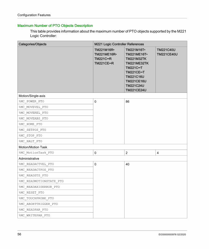
Configuration Features
Maximum Number of PTO Objects DescriptionThis table provides information about the maximum number of PTO objects supported by the M221 Logic Controller:
Categories/Objects M221 Logic Controller ReferencesTM221M16R•TM221ME16R•TM221C••RTM221CE••R
TM221M16T•TM221ME16T•TM221M32TKTM221ME32TKTM221C••TTM221CE••TTM221C16UTM221CE16UTM221C24UTM221CE24U
TM221C40UTM221CE40U
Motion/Single-axis%MC_POWER_PTO 0 86%MC_MOVEVEL_PTO%MC_MOVEREL_PTO%MC_MOVEABS_PTO%MC_HOME_PTO%MC_SETPOS_PTO%MC_STOP_PTO%MC_HALT_PTOMotion/Motion Task%MC_MotionTask_PTO 0 2 4Administrative%MC_READACTVEL_PTO 0 40%MC_READACTPOS_PTO%MC_READSTS_PTO%MC_READMOTIONSTATE_PTO%MC_READAXISERROR_PTO%MC_RESET_PTO%MC_TOUCHPROBE_PTO%MC_ABORTTRIGGER_PTO%MC_READPAR_PTO%MC_WRITEPAR_PTO
56 EIO0000000976 02/2020

Configuration Features
Task Structure
Section 2.2Task Structure
What Is in This Section?This section contains the following topics:
Topic PageTasks and Scan Modes 58Maximum Number of Tasks and Priorities 61
EIO0000000976 02/2020 57

Configuration Features
Tasks and Scan Modes
OverviewThe Modicon TM221M Logic Controller supports the following task types: Master task Periodic task Event taskThe master tasks can be configured in either of the following scan modes: Freewheeling mode Periodic modeFor more information, refer to the Configuring Program Behavior and Tasks (see EcoStruxure Machine Expert - Basic, Operating Guide).
TasksMaster tasks are triggered by continuous cyclic scanning or by the software timers by specifying the scan period 1...150 ms (default 100 ms) in the periodic mode.Periodic tasks are triggered by software timers, so are configured by specifying the scan period 1...255 ms (default 255 ms) in the periodic mode.Event tasks are triggered by the physical inputs or the HSC function blocks. These events are associated with embedded digital inputs (%I0.2...%I0.5) (rising, falling or both edges) or with the high speed counters (when the count reaches the high speed counter threshold). You can configure up to two events for each HSC function block, depending on the configuration.You must configure one priority for each event task. The priority range is 0...7 and the priority 0 has the highest priority.
58 EIO0000000976 02/2020

Configuration Features
Scan ModesThe freewheeling mode is a continuous cyclic scanning mode. In this mode, a new scan starts immediately after the previous scan has completed.This figure presents the relationship between master tasks and periodic tasks when the master task is in freewheeling mode:
In freewheeling mode, the master task sleep time is at least 30% of the total cycle time with a minimum of 1 millisecond. This percentage may be higher depending on the user application (periodic task scan time, event task scan time, communication interaction, and so on).In periodic mode, the logic controller waits until the configured scan time has elapsed before starting a new scan. Every scan is therefore the same duration.This figure presents the relationship between master tasks and periodic tasks when the master task is in periodic mode:
If the processor goes to the HALTED state when the master task is configured in freewheeling mode, verify whether the periodic task scan delay time is significant in comparison to the periodic task period. If so, try: reconfiguring the master freewheeling task as a cyclic task increasing the periodic task period.Event priorities control the relationship between the event tasks, master tasks, and periodic tasks. The event task interrupts the master task and periodic task execution.
EIO0000000976 02/2020 59

Configuration Features
This figure presents the relationship between event tasks, master tasks, and periodic tasks in the periodic mode:
The event tasks are triggered by a hardware interruption that sends a task event to the event task.
Watchdog TimerYou can configure a specific application watchdog timer for the master task and periodic task. If the task execution time exceeds the configured watchdog timer period, the logic controller goes to the HALTED state.
A system watchdog timer verifies whether the program is using more than 80% of the processing capacity. In this case, the logic controller goes in the HALTED state.
60 EIO0000000976 02/2020

Configuration Features
Maximum Number of Tasks and Priorities
DescriptionThis table summarizes the task types, available scan modes for each task, scan mode triggering conditions, operator configurable ranges, maximum number of each task, and their execution priorities:
Task Type Scan Mode Triggering Condition Configurable Range Maximum Number of Tasks
Priority
Master Freewheeling Normal Not applicable 1 LowestPeriodic Software timer 1...150 ms
Periodic Periodic Software timer 1...255 ms 1 Higher than master task and lower than event tasks
Event Periodic Physical inputs %I0.2...%I0.5 4 Highest
%HSC function blocks Up to 2 events per %HSC object
4
EIO0000000976 02/2020 61

Configuration Features
Controller States and Behaviors
Section 2.3Controller States and Behaviors
IntroductionThis section provides you with information on controller states, state transitions, and behaviors in response to system events. It begins with a detailed controller state diagram and a description of each state. It then defines the relationship of output states to controller states before explaining the commands and events that result in state transitions. It concludes with information about persistent variables and the effect of EcoStruxure Machine Expert - Basic task programming options on the behavior of your system.
What Is in This Section?This section contains the following topics:
Topic PageController States Diagram 63Controller States Description 64Controller State Transitions 68Persistent Variables 72Output Behavior 74
62 EIO0000000976 02/2020

Configuration Features
Controller States Diagram
Controller States DiagramThis figure describes the controller states:
EIO0000000976 02/2020 63

Configuration Features
Controller States Description
IntroductionThis section provides a detailed description of the controller states.
NOTE: The system word %SW6 indicates the logic controller state (EMPTY, STOPPED, RUNNING, HALTED, and POWERLESS).
When using the Start In Run feature, the controller will start executing program logic when power is applied to the equipment. It is essential to know in advance how automatic reactivation of the outputs will affect the process or machine being controlled. Configure the Run/Stop input to help control the Start In Run feature. In addition, the Run/Stop input is designed to give local control over remote RUN commands. If the possibility of a remote RUN command after the controller had been stopped locally by EcoStruxure Machine Expert - Basic would have unintended consequences, you must configure and wire the Run/Stop input to help control this situation.
WARNINGUNINTENDED EQUIPMENT OPERATION Never assume that your controller is in a certain controller state before commanding a change
of state, configuring your controller options, uploading a program, or modifying the physical configuration of the controller and its connected equipment.
Before performing any of these operations, consider the effect on all connected equipment. Before acting on a controller, always positively confirm the controller state by viewing its LEDs,
confirming the condition of the Run/Stop input, checking for the presence of output forcing, and reviewing the controller status information via EcoStruxure Machine Expert - Basic.
Failure to follow these instructions can result in death, serious injury, or equipment damage.
WARNINGUNINTENDED MACHINE START-UP Confirm that the automatic reactivation of the outputs does not produce unintended
consequences before using the Start In Run feature. Use the Run/Stop input to help control the Start In Run feature and to help prevent the
unintentional start-up from a remote location. Verify the state of security of your machine or process environment before applying power to
the Run/Stop input or before issuing a Run command from a remote location.Failure to follow these instructions can result in death, serious injury, or equipment damage.
64 EIO0000000976 02/2020

Configuration Features
When using the Unconditional Start In Run feature, the controller will attempt to start executing program logic when power is applied to the equipment, independent of the reason the controller had previously stopped. This occurs even if there is no charge in the battery, or if the battery is not present. Therefore, the controller will start with all memory values re-initialized to zero or other predetermined default values. It is conceivable that if the controller attempts to restart, for example, after a short power outage, the values in memory at the time of the outage would be lost, and restarting the machine may have unintended consequences as there was no battery to maintain memory values. It is essential to know in advance how an unconditional start will affect the process or machine being controlled. Configure the Run/Stop input to help control the Unconditional Start In Run feature.
For more information about the Unconditional Start In Run feature, refer to Application Behavior (see EcoStruxure Machine Expert - Basic, Operating Guide).
Controller States TableThis table provides detailed description of the controller operating states:
WARNINGUNINTENDED MACHINE OPERATION Conduct a thorough risk analysis to determine the effects, under all conditions, of configuring
the controller with the Unconditional Start In Run feature. Use the Run/Stop input to help avoid an unwanted unconditional restart.Failure to follow these instructions can result in death, serious injury, or equipment damage.
Controller State Description Communication Application Execution
LEDPWR RUN ERR
BOOTING The logic controller does not have a valid firmware.The communication channels are enabled to allow updating of the runtime firmware.It is not possible to login with EcoStruxure Machine Expert - Basic.Outputs are set to initialization values (see page 74).
Restricted No On Off On
EIO0000000976 02/2020 65

Configuration Features
EMPTY This state indicates that there is not a valid application.It is possible to login with EcoStruxure Machine Expert - Basic (download/animation table).Inputs are forced to 0.Outputs are set to initialization values (see page 74).
Yes No On Off 1 flash
STOPPED This state indicates that the logic controller has a valid application which is stopped.Inputs are read.Outputs are set to fallback values (see page 76), or forced values (see page 76) from EcoStruxure Machine Expert - Basic.Status alarm output is set to 0.
Yes No On Flashing Off
RUNNING This state indicates that the logic controller is executing the application.Inputs are read by the application tasks.Outputs are written by the application tasks, or from EcoStruxure Machine Expert - Basic in online mode (animation table, output forcing (see page 76)).Status alarm output is set to 1.
Yes Yes On On Off
Controller State Description Communication Application Execution
LEDPWR RUN ERR
66 EIO0000000976 02/2020

Configuration Features
NOTE: The system word %SW6 indicates the logic controller state (EMPTY, STOPPED, RUNNING, HALTED, and POWERLESS).
HALTED This state indicates that the application is stopped because an application or system watchdog timeout error has been detected. (see page 213)Objects retain their values, allowing analysis of the cause of the detected error. The tasks are stopped at the last instruction.The communication capabilities are the same as in STOPPED state.Inputs are not read, and keep their last values.Outputs are set to fallback values (see page 76).Status alarm output is set to 0.
Yes No On Flashing On
POWERLESS This state indicates that the logic controller is powered only by the USB cable. This mode can be used to update the firmware (by USB) or to download/upload the user application (by USB).To change the state of the logic controller, connect the main power so that the logic controller boots and reloads the installed components.It is possible to login with EcoStruxure Machine Expert - Basic (download/upload/animation table).Inputs are forced to 0.Outputs are set to initialization values (see page 74).
Yes (only USB) No Off Flashing Off
Controller State Description Communication Application Execution
LEDPWR RUN ERR
EIO0000000976 02/2020 67

Configuration Features
Controller State Transitions
Boot ControllerEffect: Command a reboot of the logic controller. For details about power-on sequence, refer to the controller states diagram (see page 63).Methods: Power cycle Reboot by script The script on an SD card can issue a REBOOT as its last command.
Application DownloadEffect: Download the application into the logic controller memory.Optionally, select the Reset Memories option to reset to 0 (default choice) or retain the present value of all memory words and bits on application download (see EcoStruxure Machine Expert - Basic, Operating Guide).Methods: EcoStruxure Machine Expert - Basic online button: Select the PC to controller (download) command.
Effect: Erase the application in the logic controller and set the logic controller in EMPTY state. Download the application into the logic controller memory. If download is successful, a Cold Start is done and the logic controller is set in STOPPED state.
Application file transfer by SD card: Effect: At the next reboot, erase the application in the logic controller and download the
application files from the SD card to the controller memory. If download is successful, a Cold Start is done and the controller is set in STOPPED state.
Initialize ControllerEffect: Set the controller in EMPTY state, and then, after a Cold Start, in STOPPED state.
Methods: EcoStruxure Machine Expert - Basic online button: Select the Initialize controller command.
Remote Graphic Display (see page 921).
68 EIO0000000976 02/2020

Configuration Features
RUN ControllerEffect: Command a transition to the RUNNING controller state.
Methods: Run/Stop (see page 568) switch on front face: It commands a transition to RUNNING state on rising edge.
Run/Stop (see page 568) input: The input must be configured in the application (Configuring Digital Inputs (see page 97)). It commands a transition to RUNNING state on rising edge.
EcoStruxure Machine Expert - Basic online button: Select the Run Controller command.
Application starting mode (see EcoStruxure Machine Expert - Basic, Operating Guide) setting: Start in Run, Start in Previous State, or Unconditional Start in Run
Remote Graphic Display (see page 921).
STOP ControllerEffect: Command a transition to the STOPPED state.
Methods: Run/Stop (see page 568) switch on front face: It forces a transition to STOPPED state on low level.
Run/Stop (see page 568) input: The input must be configured in the application (Configuring Digital Inputs (see page 97)). It forces a transition to STOPPED state on low level.
EcoStruxure Machine Expert - Basic online button: Select the Stop Controller command.
Application starting mode (see EcoStruxure Machine Expert - Basic, Operating Guide) setting: Start in Stop or Start in Previous State.
Download command: It needs the controller to be set in STOPPED state (after the download the controller is in
STOPPED state).
Remote Graphic Display (see page 921).
EIO0000000976 02/2020 69

Configuration Features
Error Detected (Transition to HALTED State)Effect: Command a transition to the HALTED state.
Reasons for switching to HALTED state: Application Watchdog timeout (configured by the user) (see EcoStruxure Machine Expert -
Basic, Operating Guide) System Watchdog timeout (system overrun, over 80% of the processing capacity is used)
(see page 60)
70 EIO0000000976 02/2020

Configuration Features
Cold StartCold Start is defined to be a power-up with all data initialized to its default values, and program started from the beginning with program variables cleared. Software and hardware settings are initialized.Cold Start occurs for the following reasons: Boot controller without validated application online modification. Apply power to a logic controller without a charged backup battery. Download application Initialize logic controllerEffects of the Cold Start: Initialize the function blocks. Clear the user memory. Put system objects %S and system words %SW to their initial values. Reload parameters from post configuration (changes in the post configuration are applied). Restore application from non-volatile memory (unsaved online changes are lost). Restart the internal components of the controller.
Warm StartThe Warm Start resumes running the program, in its previous operating state, with the counters, function blocks, and system words and bits maintained.
EIO0000000976 02/2020 71

Configuration Features
Persistent Variables
Automatic Save on Power OutageThe controller automatically saves the first 50 memory words (%MW0 to %MW49) in the non-volatile memory following any interruption of power. The data is restored to the memory word region during the initialization, even if the controller performs a cold start due to a missing or depleted battery.These automatically saved persistent variables are reinitialized: After each new download, if the Reset Memories checkbox is selected in download settings
(see EcoStruxure Machine Expert - Basic, Operating Guide). Following an initialization command. On system bit %S0 activation (refer to System Bits (see page 241)).
Save by User RequestYou can save memory words in the non-volatile memory or in the SD card. To perform the save operation:1. Select the destination with %S90 (refer to System Bits (see page 241)): Set to 0: non-volatile memory (default) Set to 1: SD card
2. Set the number of memory words to be saved in the system word %SW148 (refer to System Words (see page 253)).
3. Set the system bit %S93 to 1 (refer to System Bits (see page 241)).When the save operation is finished: The system bit %S93 is reset to 0. The system bit %S92 is set to 1, indicating that memory words have been successfully saved in
non-volatile memory (%S90 set to 0). The system word %SW147 indicates the SD card operation result (%S90 set to 1).
NOTE: You can initiate a memory save while the logic controller is in the RUNNING state. However, depending on the number of memory variables you specify, the save operation may not be accomplished within a single logic scan cycle. As a consequence, the memory values may not necessarily be consistent because the value of the memory variables can change from one scan to another. If you wish to have a consistent set of values for the variables, consider first putting the logic controller into the STOPPED state.
72 EIO0000000976 02/2020

Configuration Features
Restore by User RequestYou can restore the previously saved memory words. To perform the restore operation:1. Set the system bit %S92 to 1.
The non-volatile memory operation has no effect if %S92 is 0 (no values were previously saved).2. Select the source with %S90 (refer to System Bits (see page 241)): Set to 0: non-volatile memory (default) Set to 1: SD card
3. To restore from the non-volatile memory, set the number of memory words in the system word %SW148 (refer to System Words (see page 253)). When restoring from SD card, the complete Memory Variables.csv file is processed.
4. Set the system bit %S94 to 1 (refer to System Bits (see page 241)).When the restore operation is finished: The system bit %S94 is reset to 0 by the system. The system word %SW148 is updated with the number of objects restored (for example if you
specify 100 words to restore and only 50 had previously been saved, the value of %SW148 will be 50).
The system word %SW147 indicates the SD card operation result (%S90 set to 1).
Delete by User RequestYou can delete the previously saved memory words on the non-volatile memory. To perform the delete operation: Set the system bit %S91 to 1 (refer to System Bits (see page 241)). When the delete operation is finished, the system bits %S91 and %S92 and the system word
%SW148 are reset to 0 by the logic controller.This operation does not erase the variables in RAM memory.NOTE: It is not possible to delete only selected variables; the entire set of saved variables is deleted (meaning %SW148 has no impact on the erase operation, the erase operation is carried out regardless of the value of %SW148).
EIO0000000976 02/2020 73

Configuration Features
Output Behavior
IntroductionThe controller defines output behavior in response to commands and system events in a way that allows for greater flexibility. An understanding of this behavior is necessary before discussing the commands and events that affect controller states.The possible output behaviors and the controller states to which they apply are: Managed by application Initialization values Fallback behavior (see EcoStruxure Machine Expert - Basic, Operating Guide) Fallback values Maintain values
Output forcing
Managed by ApplicationYour application manages outputs normally. This applies in the RUNNING state.
Hardware Initialization ValuesThis output state applies in the BOOTING, EMPTY, and POWERLESS states.
In the initialization state, the outputs assume the following values: For embedded outputs: Fast source transistor output: 0 Vdc Fast sink transistor output: 24 Vdc Regular source transistor output: 0 Vdc Regular sink transistor output: 24 Vdc Relay output: Open
For expansion module outputs: Regular source transistor output: 0 Vdc Regular sink transistor output: 24 Vdc Relay output: Open
Software Initialization ValuesThis output state applies when downloading or when resetting the application. It applies at the end of the download or at the end of a warm start or cold start. Input objects (%I and %IW), network objects (%QWE and %QWM), and Modbus Serial IOScanner input objects (%IN and %IWN) are set to 0. Output objects (%Q and %QW), network objects (%IWE and %IWM), and Modbus Serial IOScanner output objects (%QN and %QWN) are set according to the selected fallback behavior.
74 EIO0000000976 02/2020

Configuration Features
Fallback ManagementThe objective of the fallback behavior is to control the outputs when the controller leaves the RUNNING state.
Fallback values are applied on the transition from RUNNING to STOPPED or HALTED states, except for special cases described below.
Fallback Behavior ConfigurationFallback behavior is configured on the Programming tab, Tasks → Behavior window: When Fallback values is selected, on a fallback occurrence, output values take the values
configured in Fallback value. When Maintain values is selected, outputs keep their values on a fallback occurrence, except
for outputs configured in pulse generator (PWM, PLS, PTO, FREQGEN) or reflex functions.
Fallback ExecutionOn a fallback occurrence: If Fallback values is selected, the outputs take the values configured in Fallback value. If Maintain values is selected, the outputs keep their values.Special cases: Alarm output, PTO, and FREQGEN: The fallback is never applied. Their fallback values are
forced to 0. PLS, PWM) and reflex outputs: If Fallback values is selected, the outputs take the values configured in Fallback value. If Maintain values is selected, the outputs are set to 0.
NOTE: After a download, the outputs are set to their fallback values. In EMPTY state, the outputs are set to 0. As the data image reflects the physical values, fallback values are also applied to the data
image. However, using system bit %S9 to apply fallback values does not modify the values of the data image.
EIO0000000976 02/2020 75

Configuration Features
Fallback ValuesThis output state applies in the STOPPED and HALTED states.
During fallback, the outputs assume the following values: For embedded outputs: Fast transistor output: according to fallback setting Regular transistor output: according to fallback setting Relay output: according to fallback setting Expert I/O functions (HSC, PLS, PWM, PTO, and FREQGEN):
- Source output: 0 Vdc - Sink output: 24 Vdc
For expansion module outputs: Regular transistor output: according to fallback setting Relay output: according to fallback setting
NOTE: An exception to the application of fallback values is in the case of an I/O expansion bus error. For more information, refer to I/O Configuration General Description (see page 127).
Output ForcingThe controller allows you to force the state of selected outputs to a defined value for the purposes of system testing, commissioning, and maintenance.You can force the value of an output while your controller is connected to EcoStruxure Machine Expert - Basic or with a TMH2GDB Remote Graphic Display (see page 928).To do so, either use the Force command in an animation table, or force the value using the F0 or F1 buttons in the Ladder editor.Output forcing overrides all other commands to an output irrespective of the task logic that is being executed.The forcing is not released by any online change nor logout of EcoStruxure Machine Expert - Basic.The forcing is automatically released by Cold Start (see page 71) and Download application (see page 68) command.The forcing does not apply for expert I/O functions (HSC, PLS, PWM, PTO, and FREQGEN).
76 EIO0000000976 02/2020

Configuration Features
Output RearmingIn the case of a short-circuit or current overload, the common group of outputs automatically enters into thermal protection mode (all outputs in the group are set to 0), and are then periodically rearmed (each second) to test the connection state. However, you must be aware of the effect of this rearming on the machine or process being controlled.NOTE: The output rearming does not apply to sink outputs.
NOTE: Only the short-circuit between an output set to TRUE and 0 V is detected. The short-circuit between an output set to FALSE and 24 V is not detected.
If necessary, you can use system bits and words to both detect that a short circuit or overload has occurred and on which cluster of outputs it has occurred. System bit %S10 can be used to detect within your program that an output error has occurred. You can then use the system word %SW139 to determine programmatically in which cluster of outputs a short circuit or overload has occurred.The automatic rearming feature can be disabled by setting the system bit %S49 to 0 (%S49 is set to 0 by default).
WARNINGUNINTENDED EQUIPMENT OPERATION You must have a thorough understanding of how forcing will affect the outputs relative to the
tasks being executed. Do not attempt to force I/O that is contained in tasks that you are not certain will be executed
in a timely manner, unless your intent is for the forcing to take affect at the next execution of the task whenever that may be.
If you force an output and there is no apparent affect on the physical output, do not exit EcoStruxure Machine Expert - Basic without removing the forcing.
Failure to follow these instructions can result in death, serious injury, or equipment damage.
WARNINGUNINTENDED MACHINE START-UPInhibit the automatic rearming of outputs if this feature is an undesirable behavior for your machine or process.Failure to follow these instructions can result in death, serious injury, or equipment damage.
EIO0000000976 02/2020 77

Configuration Features
Post Configuration
Section 2.4Post Configuration
IntroductionThis section describes how to manage and configure the post configuration file of the Modicon M221 Logic Controller.
What Is in This Section?This section contains the following topics:
Topic PagePost Configuration 79Post Configuration File Management 81
78 EIO0000000976 02/2020

Configuration Features
Post Configuration
IntroductionPost configuration is an option that allows you to modify some parameters of the application without changing the application. Post configuration parameters are defined in a file called Machine.cfg, which is stored in the controller.By default, all communication parameters are set in the configuration of the application. However, under certain conditions, some or all of these parameters can be modified automatically via the mechanism Post Configuration. One or more communication parameters can be specified in the post configuration file, and those parameters can override the parameters specified by the configuration. For example, one parameter may be stored in the post configuration file to change the Ethernet IP address of the controller while leaving the other Ethernet parameters, such as the gateway address, unchanged.
ParametersThe post configuration file allows you to modify network parameters.Ethernet parameters: Address configuration mode IP address Subnet mask Gateway address Device nameSerial line parameters, for each serial line in the application (embedded port or TMC2SL1 cartridge): Physical medium Baud rate Parity Data bits Stop bit Modbus address Polarization (for RS-485)
EIO0000000976 02/2020 79

Configuration Features
Operating ModeThe post configuration file is read and applied: after a Warm Start (see page 71) after a Cold Start (see page 71) after a reboot (see page 68) after an application download (see page 68) after an Ethernet reconfiguration caused by an Ethernet cable reconnection (exclusively for the
Ethernet part of the post configuration file (see page 138))For further details on controller states and transitions, refer to Controller States and Behaviors (see page 62).
80 EIO0000000976 02/2020

Configuration Features
Post Configuration File Management
IntroductionThe post configuration file can be transferred, modified, or deleted with an SD card. Refer to Post Configuration Management (see page 211).NOTE: A post configuration file example is available in the directory Firmwares & PostConfiguration\PostConfiguration\add_change\usr\cfg of the EcoStruxure Machine Expert - Basic installation directory.
Post Configuration File FormatA valid configuration must use the following format: The character '#' means beginning of comment, everything after this sign until the end of the line
is ignored. Comments are not saved in the post configuration area of the M221 Logic Controller. Rule is channel.parameter=value (no space around the '=' sign). Channel and parameter are case-sensitive. Allowed channel, parameter, and values are in the following table.
Channel Parameter Description ValueETH IPMODE Address configuration mode 0 = Fixed
1 = BOOTP2 = DHCP
IP IP address Dotted decimal stringMASK Subnet mask Dotted decimal stringGATEWAY Gateway address Dotted decimal stringNETWORKNAME Device name on the network ASCII string (maximum 16 characters)
SL1SL2
HW Physical medium 0 = RS-2321 = RS-485
BAUDS Data transmission rate 1200, 2400, 4800, 9600, 19200, 38400, 57600 or 115200
PARITY Parity for error detection 0 = None1 = Odd2 = Even
DATAFORMAT Data format 7 or 8STOPBIT Stop bit 1 or 2MODBUSADDR Modbus address 1...247POLARIZATION Polarization (for cartridges
only)0 = No1 = Yes
EIO0000000976 02/2020 81

Configuration Features
NOTE: When using a post configuration file for Ethernet configuration, it is not mandatory to specify all the parameters: If the M221 Logic Controller is configured (by the user application) in DHCP or BOOTP mode,
the network parameters IP (IP address), MASK (subnet mask) and GATEWAY (gateway address) are not configured in the file.
If a parameter is not configured in the post configuration file, the M221 Logic Controller uses the value configured in the user application (see Ethernet configuration (see page 137)).
If the M221 Logic Controller is configured in DHCP or BOOTP mode by the user application and if fixed IP mode (IPMODE=0) is configured in the post configuration file, configure the network parameters (IP (IP address), MASK (subnet mask) and GATEWAY (gateway address)) as they are not configured by the user application. Otherwise, the M221 Logic Controller starts with the default Ethernet configuration.
Post Configuration File TransferAfter creating and modifying your post configuration file, it must be transferred to the logic controller. The transfer is performed by copying the post configuration file to an SD card with a script.Refer to Adding or Changing a Post Configuration (see page 211).
Modifying a Post Configuration FileUse a text editor to modify the post configuration file on the PC.NOTE: Do not change the text file encoding. The default encoding is ANSI.NOTE: The Ethernet parameters of the post configuration file can be modified with EcoStruxure Machine Expert - Basic. For more information, refer to Connecting to a Logic Controller (see EcoStruxure Machine Expert - Basic, Operating Guide).
Deleting the Post Configuration FileRefer to Removing a Post Configuration File (see page 212).NOTE: The parameters defined in the application will be used instead of the corresponding parameters defined in the post configuration file.
82 EIO0000000976 02/2020

Modicon M221Configuring the M221 Logic ControllerEIO0000000976 02/2020
Configuring the M221 Logic Controller
Chapter 3Configuring the M221 Logic Controller
OverviewThis part provides information about how to configure the M221 Logic Controller references.
What Is in This Chapter?This chapter contains the following sections:
Section Topic Page3.1 How to Configure a Controller 843.2 Embedded Input/Output Configuration 963.3 I/O Bus Configuration 1263.4 Embedded Communication Configuration 1373.5 SD Card 198
EIO0000000976 02/2020 83

Configuring the M221 Logic Controller
How to Configure a Controller
Section 3.1How to Configure a Controller
OverviewThis chapter describes how to build a configuration in EcoStruxure Machine Expert - Basic and configure the M221 Logic Controller.
What Is in This Section?This section contains the following topics:
Topic PageBuilding a Configuration 85Optional I/O Expansion Modules 90Configuring the M221 Logic Controller 94Updating Firmware using Executive Loader Wizard 95
84 EIO0000000976 02/2020

Configuring the M221 Logic Controller
Building a Configuration
IntroductionConfigure a controller by building a configuration in EcoStruxure Machine Expert - Basic. To build a configuration, first create a new project or open an existing project.Refer to EcoStruxure Machine Expert - Basic Operating Guide for information on how to: create or open an existing project replace the default logic controller add an expansion module to the logic controller add a cartridge to the logic controller save the project.Some general information about the EcoStruxure Machine Expert - Basic user interface is provided below.
EcoStruxure Machine Expert - Basic WindowOnce you have selected a project to work with, EcoStruxure Machine Expert - Basic displays the main window.At the top of the main window, a toolbar (see EcoStruxure Machine Expert - Basic, Operating Guide) contains icons that allow you to perform common tasks, including opening the Start Menu.Next to the toolbar, the status bar (see EcoStruxure Machine Expert - Basic, Operating Guide) displays informational messages about the state of the connection to the logic controller.Below the toolbar and the status bar, the main window is divided into a number of modules. Each module controls a different stage of the development cycle, and is accessible by clicking the module tab.This figure presents the toolbar, status bar, and the module tabs in the main window:
1 Toolbar2 Status bar3 Tabs
EIO0000000976 02/2020 85

Configuring the M221 Logic Controller
Hardware TreeThe hardware tree is displayed on left-hand side in the Configuration window. It shows a structured view of the hardware configuration. When you add a controller, an expansion module, or a cartridge to the project, several nodes are automatically added to the hardware tree.NOTE: The nodes in the hardware tree are specific to the controller and the hardware configuration. These nodes depend on the I/O functions that the controller, expansion modules, and cartridges provide.
Item DescriptionToolbar Provides easy access to commonly used functions.
For more information, refer to the Toolbar (see EcoStruxure Machine Expert - Basic, Operating Guide).
Status bar Displays status and information messages on the system status.For more information, refer to the Status bar (see EcoStruxure Machine Expert - Basic, Operating Guide).
Tabs To develop an application, work your way through the module tabs from left to right: Properties
Set up the project properties. Configuration
Replicate and configure the hardware configuration of the logic controller and associated expansion modules.
ProgrammingDevelop the program in one of the supported programming languages.
DisplayBuild an operator interface for a Remote Graphic Display device.Refer to the TMH2GDB Remote Graphic Display User Guide (see page 883) for details.
CommissioningManage the connection between EcoStruxure Machine Expert - Basic and the logic controller, upload/download applications, test, and commission the application.
86 EIO0000000976 02/2020

Configuring the M221 Logic Controller
This figure presents the hardware tree of the controller configuration:
Item DescriptionDigital inputs Use to configure the embedded digital inputs of the logic controller.Digital outputs Use to configure the embedded digital outputs of the logic controller.Analog inputs Use to configure the embedded analog inputs of the logic controller.High Speed Counters Use to configure the embedded high speed counting functions (HSC).Pulse Generators Use to configure the embedded pulse generator functions
(PLS/PWM/PTO/FREQGEN).IO Bus Use to configure the expansion modules and cartridges connected to the
logic controller.ETH1 Use to configure the embedded Ethernet communications.Modbus TCP Use to configure the Modbus TCP protocol for Ethernet communications.EtherNet/IP adapter Use to configure the EtherNet/IP adapter for Ethernet communications.SLn (Serial line) Use to configure the embedded serial line or the serial line added using a
cartridge.n Serial line number (1 or 2, controller-specific).
EIO0000000976 02/2020 87

Configuring the M221 Logic Controller
EditorThe editor area is displayed in center of the Configuration window. It displays the graphical representation of hardware configuration of the devices. The hardware configuration in a project can be: only a controller a controller with cartridges a controller with expansion modules a controller with cartridges and expansion modules.The editor area displays: a short description about the device when you click the device image or when you click the
device node in the hardware tree. configuration properties of the item selected in the hardware tree.If you add an expansion module to the configuration, the expansion module appears at the right-hand side of the controller or the previously added expansion module. Cartridges are added on the controller in the cartridge slot.When configuring a controller, a cartridge, or an expansion module, the configuration properties of the node selected in the hardware tree are displayed below the graphical configuration. These properties allow you to configure the device.This figure presents the configuration of a controller with an expansion module (the controller is selected):
88 EIO0000000976 02/2020

Configuring the M221 Logic Controller
CatalogThe catalog area is displayed on right-hand side in the Configuration window. It displays the complete range of the logic controllers, expansion modules, and cartridges that can be configured using EcoStruxure Machine Expert - Basic. It also provides a short description of the selected device.You can drag-and-drop the objects from the catalog area to the editor area. You can also replace the existing controller by a different controller with simple drag-and-drop from the catalog.This figure presents the catalog of the logic controllers and the expansion modules:
EIO0000000976 02/2020 89

Configuring the M221 Logic Controller
Optional I/O Expansion Modules
PresentationI/O expansion modules can be marked as optional in the configuration. The Optional module feature provides a more flexible configuration by the acceptance of the definition of modules that are not physically attached to the logic controller. Therefore, a single application can support multiple physical configurations of I/O expansion modules, allowing a greater degree of scalability without the necessity of maintaining multiple application files for the same application.Without the Optional module feature, when the logic controller starts up the I/O expansion bus (following a power cycle, application download or initialization command), it compares the configuration defined in the application with the physical I/O modules attached to the I/O bus. Among other diagnostics made, if the logic controller determines that there are I/O modules defined in the configuration that are not physically present on the I/O bus, an error is detected and the I/O bus does not start.With the Optional module feature, the logic controller ignores the absent I/O expansion modules that you have marked as optional, which then allows the logic controller to start the I/O expansion bus.The logic controller starts the I/O expansion bus at configuration time (following a power cycle, application download, or initialization command) even if optional expansion modules are not physically connected to the logic controller. The following module types can be marked as optional: TM3 I/O expansion modules TM2 I/O expansion modulesNOTE: TM3 Transmitter/Receiver modules (TM3XTRA1 and the TM3XREC1) and TMC2 cartridges cannot be marked as optional.The application must be configured with a functional level (see EcoStruxure Machine Expert - Basic, Operating Guide) of at least Level 3.2 for modules marked as optional to be recognized as such by the logic controller.You must be fully aware of the implications and impacts of marking I/O modules as optional in your application, both when those modules are physically absent and present when running your machine or process. Be sure to include this feature in your risk analysis.
WARNINGUNINTENDED EQUIPMENT OPERATIONInclude in your risk analysis each of the variations of I/O configurations that can be realized marking I/O expansion modules as optional, and in particular the establishment of TM3 Safety modules (TM3S…) as optional I/O modules, and make a determination whether it is acceptable as it relates to your application.Failure to follow these instructions can result in death, serious injury, or equipment damage.
90 EIO0000000976 02/2020

Configuring the M221 Logic Controller
Marking an I/O Expansion Module as Optional in Offline ModeTo add a module and mark it as optional in the configuration:
To mark an existing I/O expansion module as optional in the configuration:
Optional I/O Expansion Modules in Online ModeEcoStruxure Machine Expert - Basic operates in online mode when a physical connection to a logic controller has been established.When in EcoStruxure Machine Expert - Basic online mode, the modification of the Optional module feature is disabled. You can visualize the downloaded configuration in the application: An I/O expansion module represented in yellow is marked as optional and not physically
connected to the logic controller at start-up. An information message to that effect is displayed in the Device information area.
An I/O expansion module represented in red is not marked as optional and not detected at start-up. An information message to that effect is displayed in the Device information area.
Step Action1 Drag-and-drop the I/O expansion module from the catalog to the editor.2 In the Device information area, select the Optional module check box:
Step Action1 Select the I/O expansion module in the editor.2 In the Device information area, select the Optional module check box.
EIO0000000976 02/2020 91

Configuring the M221 Logic Controller
The selection of the Optional module feature is used by the logic controller to start the I/O bus. The following system words are updated to indicate the status of the physical I/O bus configuration:
For more information, refer to System Words (see page 253).
System Word Comment%SW118Logic controller status word
Bits 13 and 14 are pertinent to the I/O module status relative to the I/O bus. Bit 13, if FALSE, indicates that there are mandatory modules as defined by the I/O expansion bus configuration that are absent or otherwise inoperative when the logic controller attempts to start the I/O expansion bus. In this case, the I/O bus does not start.Bit 14, if FALSE, indicates that one or more modules have ceased communication with the logic controller after the I/O expansion bus is started. This is the case whether an I/O expansion module is defined as mandatory or as an optional module but present at start-up.
%SW119I/O expansion module configuration
Each bit, starting with bit 1 (bit 0 is reserved), is dedicated to a configured I/O expansion module and indicates whether the module is optional (TRUE) or mandatory (FALSE) when the controller attempts to start the I/O bus.
%SW120I/O expansion module status
Each bit, starting with bit 1 (bit 0 is reserved), is dedicated to a configured I/O expansion module and indicates the status of the module.When the logic controller attempts to start the I/O bus, if the value of %SW120 is non-zero (indicating that an error is detected for at least one of the modules), the I/O expansion bus does not start unless the corresponding bit in %SW119 is set to TRUE (indicating the module is marked as an optional module).When the I/O bus is started, if the value of %SW120 is modified by the system, it indicates that an error is detected on one or more I/O expansion modules (regardless of the Optional module feature).
92 EIO0000000976 02/2020

Configuring the M221 Logic Controller
Shared Internal ID CodesLogic controllers identify expansion modules by a simple internal ID code. This ID code is not specific to each reference, but identifies the structure of the expansion module. Therefore, different references can share the same ID code.If you declare two modules with the same internal ID code next to each other in the configuration and both are declared as optional, a message appears at the bottom of the Configuration window. There must be at least one non-optional module between two optional modules.This table groups the module references sharing the same internal ID code:
Modules sharing the same internal ID codeTM2DDI16DT, TM2DDI16DKTM2DRA16RT, TM2DDO16UK, TM2DDO16TKTM2DDI8DT, TM2DAI8DTTM2DRA8RT, TM2DDO8UT, TM2DDO8TTTM2DDO32TK, TM2DDO32UKTM3DI16K, TM3DI16/GTM3DQ16R/G, TM3DQ16T/G, TM3DQ16TK, TM3DQ16U, TM3DQ16UG, TM3DQ16UKTM3DQ32TK, TM3DQ32UKTM3DI8/G, TM3DI8ATM3DQ8R/G, TM3DQ8T/G, TM3DQ8U, TM3DQ8UGTM3DM8R/GTM3DM24R/GTM3SAK6R/GTM3SAF5R/GTM3SAC5R/GTM3SAFL5R/GTM3AI2H/GTM3AI4/GTM3AI8/GTM3AQ2/GTM3AQ4/GTM3AM6/GTM3TM3/GTM3TI4/GTM3TI4D/GTM3TI8T/G
EIO0000000976 02/2020 93
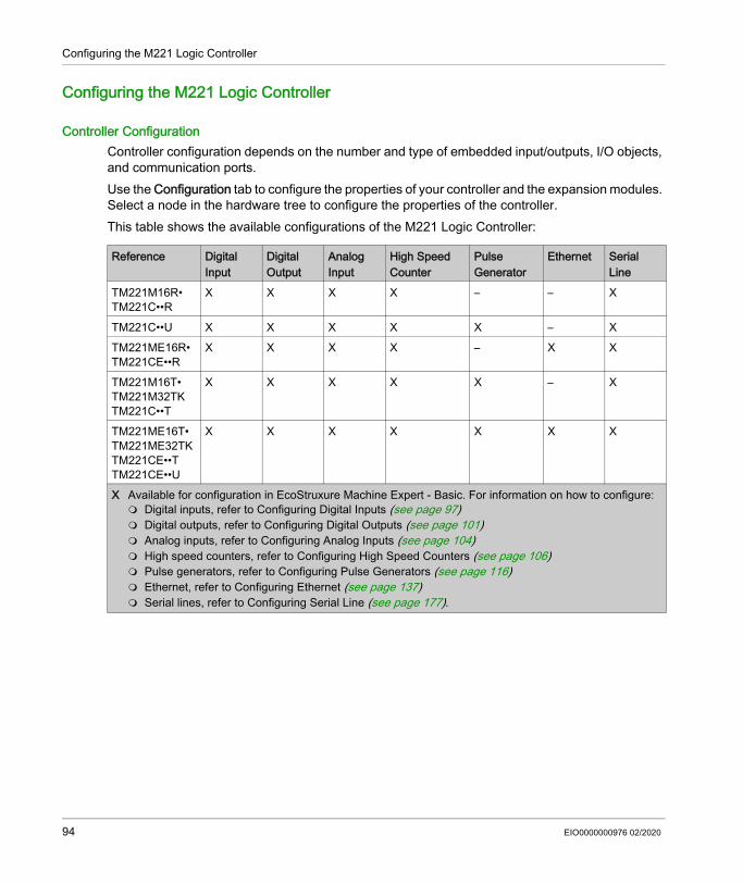
Configuring the M221 Logic Controller
Configuring the M221 Logic Controller
Controller ConfigurationController configuration depends on the number and type of embedded input/outputs, I/O objects, and communication ports.Use the Configuration tab to configure the properties of your controller and the expansion modules. Select a node in the hardware tree to configure the properties of the controller.This table shows the available configurations of the M221 Logic Controller:
Reference Digital Input
Digital Output
Analog Input
High Speed Counter
Pulse Generator
Ethernet Serial Line
TM221M16R•TM221C••R
X X X X – – X
TM221C••U X X X X X – XTM221ME16R•TM221CE••R
X X X X – X X
TM221M16T•TM221M32TKTM221C••T
X X X X X – X
TM221ME16T•TM221ME32TKTM221CE••TTM221CE••U
X X X X X X X
X Available for configuration in EcoStruxure Machine Expert - Basic. For information on how to configure: Digital inputs, refer to Configuring Digital Inputs (see page 97) Digital outputs, refer to Configuring Digital Outputs (see page 101) Analog inputs, refer to Configuring Analog Inputs (see page 104) High speed counters, refer to Configuring High Speed Counters (see page 106) Pulse generators, refer to Configuring Pulse Generators (see page 116) Ethernet, refer to Configuring Ethernet (see page 137) Serial lines, refer to Configuring Serial Line (see page 177).
94 EIO0000000976 02/2020

Configuring the M221 Logic Controller
Updating Firmware using Executive Loader Wizard
OverviewYou can update the firmware of the controller using the Executive Loader wizard.Refer to Controller States and Behavior (see page 62) for information concerning the state of the firmware in your controller.
Updating the Firmware of the ControllerTo launch the ExecLoader wizard, follow these steps:
Step Action1 Close all Windows applications, including virtual machines.2 Click Start → Programs → Schneider Electric → EcoStruxure Machine Expert - Basic →
EcoStruxure Machine Expert - Basic Firmware Update or run the ExecLoaderWizard.exe from EcoStruxure Machine Expert - Basic installation folder\Execloader folder.
EIO0000000976 02/2020 95

Configuring the M221 Logic Controller
Embedded Input/Output Configuration
Section 3.2Embedded Input/Output Configuration
OverviewThis chapter describes how to configure the embedded I/O objects of the M221 Logic Controller.The number of embedded inputs and outputs depends on the controller reference. For more information, refer to the tables for: TM221C Logic Controller (see page 30) TM221M Logic Controller (see page 35)
What Is in This Section?This section contains the following topics:
Topic PageConfiguring Digital Inputs 97Configuring Digital Outputs 101Configuring Analog Inputs 104Configuring High Speed Counters 106Configuring Dual Phase and Single Phase Counters 109Configuring Frequency Meter 114Configuring Pulse Generators 116Configuring Pulse (%PLS) 118Configuring Pulse Width Modulation (%PWM) 120Configuring Pulse Train Output (%PTO) 122Configuring Frequency Generator (%FREQGEN) 125
96 EIO0000000976 02/2020

Configuring the M221 Logic Controller
Configuring Digital Inputs
IntroductionBy default, all digital inputs are used as regular inputs. Some of the digital inputs are fast and can be used by configuring the high speed counters (see page 106) while other inputs can be configured as event sources.
Digital Inputs ConfigurationThis table describes how to configure the digital inputs:
Step Action1 Click the Digital inputs node in the hardware tree to display the digital input properties.
This figure shows the properties of the digital inputs in the editor area:
2 Edit the properties to configure the digital inputs.For detailed information on the digital input configuration parameters, refer to the table below.
EIO0000000976 02/2020 97

Configuring the M221 Logic Controller
This table describes each parameter of the digital input configuration:
Parameter Editable Value Default Value DescriptionUsed No True/False False Indicates whether the input channel is being used in a
program or not.Address No %I0.x – Displays the address of the digital input on the controller,
where x represents the channel number.If the controller has 8 digital input channels, x varies from 0...7.If the controller has 16 digital input channels, x varies from 0...15.For example, %I0.2 is the third digital input channel of the logic controller.
Symbol Yes – – Allows you to specify a symbol to associate with the digital input object.Double-click in the Symbol column, type the name of the symbol and press Enter.
Used by No any Filtering Displays the name of the component that uses the input channel.For example, if the input channel is used by a subroutine, this field displays User logic. The possible values in this field are: User logic Filtering Latch Run/Stop Event %HSCx
where x is the high speed counter instance on the controller
%FCywhere y is the fast counter instance on the controller
If an input is being used by more than one operation, all values, separated by commas, are displayed in this field.
Filtering Yes No Filter3 ms12 ms
3 ms Allows you to select the noise filter duration for the input channel.Using a filter for the digital inputs reduces the noise on the controller input.If you select filter for an input, you cannot configure that input for: Latch Event
98 EIO0000000976 02/2020

Configuring the M221 Logic Controller
Latch Yes True/False False Allows you to enable or disable latching for the inputs configured as events (%I0.2...%I0.5).By default, this option is disabled due to default value of Filtering. Set the Filtering to No Filter to enable the Latch option.Latching enables pulses with a duration shorter than the controller scan time to be memorized.When a pulse duration is shorter than a scan time and has a value greater than or equal to 1 ms, the controller latches the pulse, which is then updated in the next scan.If you enable Latch for an input, you cannot configure that input for: Filtering Run/Stop Event
Run/Stop Yes True/False False Allows you to configure 1 digital input as an additional Run/Stop switch.If you configure a digital input as Run/Stop switch, you cannot use the input in any other function block (for example, high speed counter function block, fast counter function block, and so on).If you enable Run/Stop for an input, you cannot configure that input for: Latch Event
Event Yes Not UsedFalling EdgeRising EdgeBoth edges
Not Used Allows you to select an event that triggers the inputs %I0.2...%I0.5. By default, this option is disabled due to the default value of Filtering. Set Filtering to No Filter to enable the Event option.When you select an event from the drop-down list (other than Not Used): The Priority parameter is enabled to allow you to set the
priority of the event. An event task is created and displayed
(see EcoStruxure Machine Expert - Basic, Operating Guide) in the Configuration tab.
Parameter Editable Value Default Value Description
EIO0000000976 02/2020 99

Configuring the M221 Logic Controller
Additional configuration details are displayed in the Programming tab. For more information, refer to Digital Inputs (%I) (see page 219).
Priority Yes 0...7 7 Allows you to set the priority of the triggering event for the inputs %I0.2...%I0.5.You can set the priority of each event using the Priority parameter that is editable only for the inputs configured as event.Assign each configured event a different priority: if 2 events have same priority, a detected error message appears in the window.
Subroutine No any empty Displays the number of the subroutine associated with an input configured as an event.
Comment Yes – – Allows you to specify a comment to associate with the digital input object.Double-click in the Comment column, type the comment and press Enter.
Parameter Editable Value Default Value Description
100 EIO0000000976 02/2020

Configuring the M221 Logic Controller
Configuring Digital Outputs
IntroductionBy default, all digital outputs are used as regular outputs. For controllers equipped with transistor outputs, 2 outputs are fast transistor outputs and can be used by configuring the pulse generators (see page 116).
Digital Outputs ConfigurationThis table describes how to configure the digital outputs:
Step Action1 Click the Digital outputs node in the hardware tree to display the digital output properties.
This figure shows the properties of the digital outputs in the editor area:
2 Edit the properties to configure the digital outputs.For detailed information on the digital output configuration parameters, refer to the table below.
EIO0000000976 02/2020 101

Configuring the M221 Logic Controller
This table describes each parameter of the digital output configuration:
Parameter Editable Value Default Value DescriptionUsed No True/False False Indicates whether the output channel is being
used in a program or not.Address No %Q0.x – Displays the address of the digital output on
the controller, where x represents the channel number.If the controller has 8 digital output channels, x varies from 0...7.If the controller has 16 digital output channels, x varies from 0...15.For example, %Q0.2 is the third digital output channel on the controller.
Symbol Yes – – Allows you to specify a symbol to associate with the digital output object.Double-click in the Symbol column, type the name of the symbol and press Enter.
Used by No any empty Displays the name of the component that uses the output channel.For example, if the output channel is used as status alarm, it displays Alarm.
Status Alarm Yes True/False False Allows you to enable or disable the status alarm for the output (%Q0.0...%Q0.7).You can configure only one output channel for the status alarm.You cannot configure an output as status alarm if the output is used in a program.The value of the status alarm is 1 when the controller is in the state RUNNING, and 0 in all other state
102 EIO0000000976 02/2020

Configuring the M221 Logic Controller
Additional configuration details are displayed in the Programming tab. For more information, refer to Digital Outputs (%Q) (see page 220).
Fallback value Yes 1 or 0 0 Specify the value to apply to this output (fallback to 0 or fallback to 1) when the logic controller enters the STOPPED or an exception state. The default value is 0. If Maintain values fallback mode is configured, the output retains its current value when the logic controller enters the STOPPED or an exception state.This field is disabled for the output configured as Status Alarm.
Comment Yes – – Allows you to specify a comment to associate with the digital output object.Double-click in the Comment column, type the comment and press Enter.
Parameter Editable Value Default Value Description
EIO0000000976 02/2020 103

Configuring the M221 Logic Controller
Configuring Analog Inputs
IntroductionThe analog inputs do not have any configurable property in EcoStruxure Machine Expert - Basic. By default, analog inputs are used as regular inputs.
Analog Inputs ConfigurationThis table describes how to configure the analog inputs:
Step Action1 Click the Analog inputs node in the hardware tree to display the analog input properties.
This figure shows the properties of the analog inputs in the editor area:
2 Edit the properties to configure the analog inputs.For detailed information on the analog input configuration parameters, refer to the table below.
104 EIO0000000976 02/2020

Configuring the M221 Logic Controller
This table describes each parameter of the analog input configuration:
Additional configuration details are displayed in the Programming tab. For more information, refer to Analog Inputs (%IW) (see page 221).
Parameter Editable Value Default Value DescriptionUsed No True/False False Indicates whether the input channel is being used in a
program or not.Address No %IW0.x – Displays the address of the analog input on the
controller, where x represents the channel number.If the controller has 2 analog input channels, x is either 0 or 1. For example, %IW0.1 is the second analog input channel on the controller.
Symbol Yes – – Allows you to specify a symbol to associate with the analog input object.Double-click in the Symbol column, type the name of the symbol and press Enter.
Type No 0 - 10 V 0 - 10 V Indicates the channel mode. For example, 0 - 10 V refers to the channel that can be used for an electrical input of voltage type in the range 0...10 V.
Scope No Normal Normal Indicates the range of values for a channel.Minimum No 0 0 Indicates the lower measurement limit.Maximum No 1000 1000 Indicates the upper measurement limit.Filter No 0 0 Indicates the filtering value. Multiply by the Filter Unit
value to obtain the filtering time.Filter Unit No 100 ms empty Specifies the unit of time for the filtering value.Sampling No – empty –Units No any empty Indicates the unit of the analog input.Comment Yes – – Allows you to specify a comment to associate with the
analog input object.Double-click in the Comment column, type the comment and press Enter.
EIO0000000976 02/2020 105

Configuring the M221 Logic Controller
Configuring High Speed Counters
IntroductionYou can configure high speed counters to perform any one of the following functions: Single Phase Dual Phase [Pulse / Direction] Dual Phase [Quadrature X1] Dual Phase [Quadrature X2] Dual Phase [Quadrature X4] Frequency MeterFor information on how to select a function, refer to High Speed Counter in Counter Modes (see page 305) or High Speed Counter in Frequency Meter Mode (see page 313).The High Speed Counter function block works at a maximum frequency of 100 kHz for all counting modes with a range of 0 to 65535 in single word and 0 to 4294967295 in double word.The High Speed Counter function blocks use dedicated inputs and auxiliary inputs and outputs. These inputs and outputs are not reserved for the exclusive use of High Speed Counter function blocks: If the dedicated input/output is not used by an HSC instance, it is available for the application
as a regular digital input/output. If the application does not use an HSC dedicated input/output as a regular digital input/output,
it is available for the corresponding HSC instance.
Single Phase I/O Assignment
Dual Phase Pulse / Direction I/O Assignment
Main Inputs Auxiliary Inputs Reflex Outputs%HSC0 %I0.0 - %I0.2 %I0.3 %Q0.2 %Q0.3%HSC1 %I0.6 - %I0.5 %I0.4 %Q0.4 %Q0.5%HSC2 %I0.1 - - - %Q0.2 %Q0.3%HSC3 %I0.7 - - - %Q0.4 %Q0.5Single Phase Pulse input Not used Preset input Catch input Reflex
output 0Reflex output 1
Main Inputs Auxiliary Inputs Reflex Outputs%HSC0 %I0.0 %I0.1 %I0.2 %I0.3 %Q0.2 %Q0.3%HSC1 %I0.6 %I0.7 %I0.5 %I0.4 %Q0.4 %Q0.5Pulse / Direction Pulse input Direction
inputPreset input Catch input Reflex
output 0Reflex output 1
106 EIO0000000976 02/2020

Configuring the M221 Logic Controller
Dual Phase Quadrature I/O Assignment
Frequency Meter I/O Assignment
High Speed Counters ConfigurationThis table describes how to configure the high speed counters:
Main Inputs Auxiliary Inputs Reflex Outputs%HSC0 %I0.0 %I0.1 %I0.2 %I0.3 %Q0.2 %Q0.3%HSC1 %I0.6 %I0.7 %I0.5 %I0.4 %Q0.4 %Q0.5Quadrature X1 Pulse input
Phase APulse input Phase B
Preset input Catch input Reflex output 0
Reflex output 1
Quadrature X2 Pulse input Phase A
Pulse input Phase B
Preset input Catch input Reflex output 0
Reflex output 1
Quadrature X4 Pulse input Phase A
Pulse input Phase B
Preset input Catch input Reflex output 0
Reflex output 1
Main Inputs Auxiliary Inputs Reflex Outputs%HSC0 %I0.0 - - - - -%HSC1 %I0.6 - - - - -Frequency Meter Pulse input Not used Not used Not used Not used Not used
Step Description1 Click the High Speed Counters node in the hardware tree.
Result: The High Speed Counters list is displayed:
2 Click ... in under Configuration to select the type of high speed counter to assign and to display the High Speed Counter Assistant window.For detailed information on the high speed counter, refer to the table below.
EIO0000000976 02/2020 107

Configuring the M221 Logic Controller
This table describes each parameter of the high speed counters configuration:
For details on the configuration of the Dual Phase [Pulse / Direction], Dual Phase [Quadrature X1], Dual Phase [Quadrature X2], Dual Phase [Quadrature X4], and Single Phase, refer to Configuring Dual Phase and Single Phase Counters (see page 109).For details on the configuration of the Frequency Meter, refer to Configuring Frequency Meter (see page 114).
Parameter Editable Value Default Value DescriptionUsed No TRUE/FALSE FALSE Indicates whether the high speed counter
is being used in a program or not.Address No %HSCi Indicates the address of the high speed
counter, where i is the object number.
Symbol Yes – – Allows you to specify a symbol to associate with the high speed counter object.Double-click in the Symbol column to edit the field.
Type No Not ConfiguredSingle PhaseDual PhaseFrequency Meter
Not Configured Indicates the counter operational mode.
Configuration Yes [...](Button)
Disabled Allows you to configure the high speed counter parameters using the High Speed Counter Assistant window.
Comment Yes – – Allows you to specify a comment to associate with the high speed counter object.Double-click in the Comment column to edit the field.
108 EIO0000000976 02/2020

Configuring the M221 Logic Controller
Configuring Dual Phase and Single Phase Counters
High Speed Counter AssistantThis figure presents an instance of the assistant window for %HSC0 configured as the Dual Phase [Pulse / Direction]:
Item Description1 Displays the title of the assistant dialog window for the selected HSC instance %HSCi.
2 Allows you to select the HSC type, mode, and dual phase counter type.3 Displays the dedicated inputs, auxiliary inputs, and reflex outputs.
Properties in this area of the assistant window are different for each counter type and the HSC instance. For more details, refer to Dedicated I/O Assignments (see page 106).
EIO0000000976 02/2020 109

Configuring the M221 Logic Controller
Common ParametersThis table describes parameters common to all counter types:
Parameter Editable Value Default Value DescriptionType of HSC Yes Not Configured
Single PhaseDual PhaseFrequency Meter
- Indicates the selected counter operational mode and allows you to change it. The options depend on the instance and on the type of HSC in the other instances. Refer to Dedicated I/O Assignments (see page 106).
Counting Mode No Free Large - Indicates the selected counter operational mode. The options depend on the instance and on the type of HSC in the other instances. Refer to Dedicated I/O Assignments (see page 106).
Input Mode Yes Pulse / DirectionQuadrature X1Quadrature X2Quadrature X4
- Indicates the selected counter operational mode and allows you to change it. The options depend on the instance and on the type of HSC in the other instances. Refer to Dedicated I/O Assignments (see page 106).
Double Word Yes TRUE/FALSE FALSE Allows you to toggle between input data size of Word (16 bits) and Double Word (32 bits).Enabling this field changes the data size from Word (16 bits) to Double Word (32 bits).
Preset Yes 0...65535(Word)
0(Word)
Allows you to specify the preset value for counting functions.
0...4294967295(Double Word)
0(Double Word)
Threshold S0 Yes 0...65535(Word)
65535(Word)
Allows you to specify the value of the HSC flag S0 that contains the value of the threshold TH0.0...4294967295
(Double Word)4294967295(Double Word)
Threshold S1 Yes 0...65535(Word)
0...65535(Word)
Allows you to specify the value for the HSC flag S1 that contains the value of the threshold TH1.0...4294967295
(Double Word)0... 4294967295(Double Word)
110 EIO0000000976 02/2020

Configuring the M221 Logic Controller
Trigger Yes Not UsedFalling EdgeRising EdgeBoth edges
Not Used Allows you to select a triggering function for an event (for both threshold TH0 and TH1) from the list.Selecting a triggering function makes the Priority parameter editable.
Priority Yes 0...7 7 Allows you to set the priority of the triggering function of an event (for both threshold TH0 and TH1).This field is greyed until you select a triggering function.
Subroutine No any empty Displays the subroutine associated with an input configured as an event (for both threshold TH0 and TH1).
Normal Input Yes TRUE/FALSE FALSE Configurable as Preset Input by selecting the Use as check box, only on %HSC0 and %HSC1, respectively %I0.2 and %I0.5.
Normal Input Yes TRUE/FALSE FALSE Configurable as Catch Input by selecting the Use as check box, only on %HSC0 and %HSC1, respectively %I0.3 and %I0.4.
Reflex Output 0 Yes TRUE/FALSE FALSE Configure Reflex output 0 %Q0.2 for either %HSC0 or %HSC2.Configure Reflex output 0 %Q0.4 for either %HSC1 or %HSC3.
Reflex Output 1 Yes TRUE/FALSE FALSE Configure Reflex output 1 %Q0.3 for either %HSC0 or %HSC2.Configure Reflex output 1 %Q0.5 for either %HSC1 or %HSC3.
Parameter Editable Value Default Value Description
EIO0000000976 02/2020 111

Configuring the M221 Logic Controller
Dual Phase [Pulse / Direction] ParametersThis table describes parameters specific to Dual Phase [Pulse / Direction]:
Value < S0 Yes TRUE/FALSE FALSE Allows you to enable or disable the condition in which the counter is constantly compared to the output value to set the reflex output when the output value is lower than the value of HSC flag S0.
S0 <= Value < S1 Yes TRUE/FALSE FALSE Allows you to enable or disable the condition in which the counter is constantly compared to the output value to set the reflex output when the output value is higher than or equals to the value of the HSC flag S0 and the output value is lower than the value of the HSC flag S1.
Value >= S1 Yes TRUE/FALSE FALSE Allows you to enable or disable the condition in which the counter is constantly compared to the output value to set the reflex output when the output value is higher than or equals to the value of HSC flag S1.
Parameter Editable Value Default Value Description
Parameter Editable Value Default Value DescriptionPulse Input No TRUE/FALSE TRUE Configured as pulse input, only on %HSC0
and %HSC1, respectively %I0.0 and %I0.6.
Direction Input No TRUE/FALSE TRUE Configured as directional input, only on %HSC0 and %HSC1, respectively %I0.1 and %I0.7. TRUE = down counting FALSE = up counting
112 EIO0000000976 02/2020

Configuring the M221 Logic Controller
Dual Phase [Quadrature X1], Dual Phase [Quadrature X2], and Dual Phase [Quadrature X4] Parameters
This table describes parameters specific to Dual Phase [Quadrature X1], Dual Phase [Quadrature X2], and Dual Phase [Quadrature X4]:
Single Phase ParametersThis table describes a parameter specific to Single Phase:
Parameter Editable Value Default Value DescriptionPulse Input Phase A
No TRUE/FALSE TRUE Configured as pulse input for phase A, only on %HSC0 and %HSC1, respectively %I0.0 and %I0.6.
Pulse Input Phase B
No TRUE/FALSE TRUE Configured as pulse input for phase B, only on %HSC0 and %HSC1, respectively %I0.1 and %I0.7.
Parameter Editable Value Default Value DescriptionPulse Input No TRUE/FALSE TRUE You can configure up to four HSC in Single
Phase HSC type, they use, as a pulse input: %I0.0 for %HSC0 %I0.6 for %HSC1 %I0.1 for %HSC2 %I0.7 for %HSC3
EIO0000000976 02/2020 113

Configuring the M221 Logic Controller
Configuring Frequency Meter
High Speed Counter AssistantThis figure presents the High Speed Counter Assistant (%HSC0) window for the counter type Frequency Meter:
114 EIO0000000976 02/2020

Configuring the M221 Logic Controller
Frequency Meter ParametersThis table describes each parameter of the High Speed Counter Assistant (%HSCi) window for the counter type Frequency Meter:
Additional configuration details are displayed in the Programming tab.For more details on the High Speed Counter function block, refer to the Modicon M221 Logic Controller Advanced Functions Library Guide, chapter High Speed Counter Function Block (%HSC) (see page 300).
Parameter Editable Value Default Value DescriptionType of HSC Yes Not Configured
Single PhaseDual PhaseFrequency Meter
Frequency Meter
Indicates the selected counter operational mode and allows you to change it.The Frequency Meter is configurable on %HSC0 and/or %HSC1. Refer to the Frequency Meter I/O Assignment (see page 107).
Double Word Yes TRUE/FALSE FALSE Use a 32-bit preset word.Enabling this field changes the data size from Word (16 bits) to Double Word (32 bits).
Time Window Yes 100 ms1 s
1 s Allows you to select the time base to measure the frequency between 100 Hz and 100 kHz.
Pulse Input No TRUE/FALSE TRUE Indicates the input used as pulse input, %I0.0 for %HSC0 or %I0.6 for %HSC1.
EIO0000000976 02/2020 115

Configuring the M221 Logic Controller
Configuring Pulse Generators
IntroductionThe pulse generator function blocks, Pulse (PLS), Pulse Width Modulation (PWM), Pulse Train Output (PTO) and Frequency Generator (FREQGEN) are used to generate square or modulated wave signals on dedicated output channels %Q0.0 or %Q0.1.
The PWM outputs feature a modulated wave signal with a variable width and duty cycle, while the PTO outputs generate a a square wave to control a linear single-axis stepper or servo drive in open loop mode. The PLS also creates a square wave for a programmed number of pulses.
Pulse Generators ConfigurationThis table describes how to configure the pulse generators:
This table describes the parameters of the pulse generator:
Step Action1 Click the Pulse Generators node in the hardware tree to display the pulse generator properties.
This figure presents the properties of the pulse generators in the editor area:
2 Edit the properties and click [...] to configure the pulse generator output.For detailed information on the pulse generator configuration parameters, refer to the table below.
Parameter Editable Value Default Value DescriptionUsed No True/False False Indicates whether the pulse generated
output is being used in a program or not.
Address No %PLSx%PWMx%PTOx%FREQGENx
%PLSx/%PWMx/%PTOx/%FREQGENx
Displays the address of the Pulse output, Pulse Width Modulation output, Pulse Train Output, or Frequency Generator where x is the output number.
Symbol Yes – – Allows you to specify a symbol to associate with the pulse generator object.Double-click in the Symbol column to edit the field.
116 EIO0000000976 02/2020

Configuring the M221 Logic Controller
PLS ConfigurationRefer to Configuring Pulse (%PLS) (see page 118).For more details on the Pulse function block, refer to the Modicon M221 Logic Controller Advanced Functions Library Guide, chapter Pulse (%PLS) (see page 318).
PWM ConfigurationRefer to Configuring Pulse Width Modulation (%PWM) (see page 120).For more details on the Pulse Width Modulation function block, refer to the Modicon M221 Logic Controller Advanced Functions Library Guide, chapter Pulse Width Modulation (%PWM) (see page 326).
PTO ConfigurationRefer to Configuring Pulse Train Output (%PTO) (see page 122)For more details on the Pulse Train Output function block, refer to the Modicon M221 Logic Controller Advanced Functions Library Guide, chapter Pulse Train Output (%PTO) (see page 418).
Frequency Generator ConfigurationRefer to Configuring Frequency Generator (%FREQGEN) (see page 122)For more details on the FREQGEN function block, refer to the Modicon M221 Logic Controller Advanced Functions Library Guide, chapter Frequency Generator (%FREQGEN) (see page 473).
Type No Not ConfiguredPLSPWMPTOFREQGEN
Not Configured Displays the type of the pulse generator used for the output channel.
Configuration
Yes [...](Button)
Enabled Allows you to configure the pulse generator using the Pulse Generator Assistant window.
Comment Yes – – Allows you to specify a comment to associate with the pulse generator object.Double-click in the Comment column to edit the field.
Parameter Editable Value Default Value Description
EIO0000000976 02/2020 117
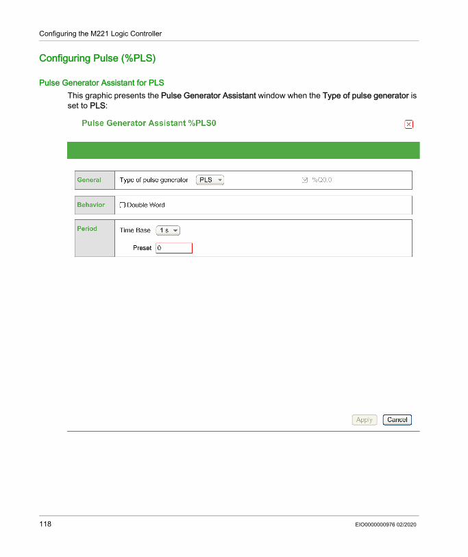
Configuring the M221 Logic Controller
Configuring Pulse (%PLS)
Pulse Generator Assistant for PLSThis graphic presents the Pulse Generator Assistant window when the Type of pulse generator is set to PLS:
118 EIO0000000976 02/2020

Configuring the M221 Logic Controller
The table describes each parameter available when the channel is configured in PLS mode:
This table presents the range of values of the Preset parameter:
Additional configuration details are displayed in the Programming tab.For more details on the Pulse function block, refer to the Modicon M221 Logic Controller Advanced Functions Library Guide, chapter Pulse (%PLS) (see page 318).
Parameter Value Default Value DescriptionType of pulse generator
Not ConfiguredPLSPWMPTOFREQGEN
PLS Allows you to choose the type of pulse generator and configure the output properties.Select: PLS to configure the output channels in PLS mode.
Refer to Configuring Pulse (%PLS) (see page 118). PWM to configure the output channels in PWM mode.
Refer to Configuring Pulse Width Modulation (%PWM) (see page 120).
PTO to configure the output channels in PTO mode. Refer to Configuring Pulse Train Output (%PTO) (see page 122).
FREQGEN to configure the output channels in FREQGEN mode. Refer to Configuring Frequency Generator (%FREQGEN) (see page 125).
Double Word True/False False Allows you to toggle between the data size of Word (16 bits) and Double Word (32 bits).By default, this parameter is disabled, which indicates that the current data size is Word (16 bits).Enabling this field changes the data size to Double Word (32 bits).
Time Base 0.1 ms1 ms10 ms1 s
1 s Allows you to select the time base for the frequency measurement.
Preset Refer to the table below for complete range of preset values for PLS type pulse generator.
0 Allows you to specify the preset value for the pulse output.
Type Time Base Preset Value RangePLS 0.1 ms 1...20000
1 ms 1...200010 ms 1...2001 s 1 or 2
EIO0000000976 02/2020 119

Configuring the M221 Logic Controller
Configuring Pulse Width Modulation (%PWM)
Pulse Generator Assistant for PWMThis graphic presents the Pulse Generator Assistant window when the Type of pulse generator is set to PWM:
120 EIO0000000976 02/2020

Configuring the M221 Logic Controller
The table describes each parameter available when the channel is configured in PWM mode:
This table presents the range of values of the Preset parameter:
Additional configuration details are displayed in the Programming tab.For more details on the Pulse Width Modulation function block, refer to the Modicon M221 Logic Controller Advanced Functions Library Guide, chapter Pulse Width Modulation (%PWM) (see page 326).
Parameter Value Default Value DescriptionType of pulse generator
Not ConfiguredPLSPWMPTOFREQGEN
PWM Allows you to choose the type of pulse generator and configure the output properties.Select: PLS to configure the output channels in PLS mode.
Refer to Configuring Pulse (%PLS) (see page 118). PWM to configure the output channels in PWM mode.
Refer to Configuring Pulse Width Modulation (%PWM) (see page 120).
PTO to configure the output channels in PTO mode. Refer to Configuring Pulse Train Output (%PTO) (see page 122).
FREQGEN to configure the output channels in FREQGEN mode. Refer to Configuring Frequency Generator (%FREQGEN) (see page 125).
Time Base 0.1 ms1 ms10 ms1 s
1 s Allows you to select the time base for the frequency measurement.
Preset Refer to the table below for complete range of preset values for PWM type pulse generator.
0 Allows you to specify the preset value for the PWM output.
Type Time Base Preset Value RangePWM 0.1 ms 1...10000
1 ms 1...100010 ms 1...1001 s 1
EIO0000000976 02/2020 121

Configuring the M221 Logic Controller
Configuring Pulse Train Output (%PTO)
Pulse Generator Assistant for PTOThis graphic presents the Pulse Generator Assistant window when the Type of pulse generator is set to PTO:
122 EIO0000000976 02/2020

Configuring the M221 Logic Controller
The table describes each parameter available when the channel is configured in PTO mode:
Parameter Value Default DescriptionGeneral Type of pulse
generatorNot ConfiguredPLSPWMPTOFREQGEN
PTO Allows you to choose the type of pulse generator and configure the output properties.Select: PLS to configure the output channels in PLS
mode. Refer to Configuring Pulse (%PLS) (see page 118).
PWM to configure the output channels in PWM mode. Refer to Configuring Pulse Width Modulation (%PWM) (see page 120).
PTO to configure the output channels in PTO mode. Refer to Configuring Pulse Train Output (%PTO) (see page 122).
FREQGEN to configure the output channels in FREQGEN mode. Refer to Configuring Frequency Generator (%FREQGEN) (see page 125).
Output mode Clock Wise / Counter Clock WisePulse / Direction
Pulse / Direction Select the pulse Output mode (see page 368).NOTE: The Clock Wise / Counter Clock Wise output mode is only valid for PTO0. This mode disables PTO1.
Pulse %Q0.0 for PTO0, %Q0.1 for PTO1
%Q0.0 for PTO0, %Q0.1 for PTO1
When Pulse / Direction is selected in Output mode, select the output that provides the motor operating speed.
Direction Not used%Q0.0...16 (depending on controller reference)
%Q0.2 When Pulse / Direction is selected in Output mode, select the output that provides the motor rotation direction.Set to Not used (disabled) if directional output is not required for the application.
NOTE: The application must be configured with a functional level of at least Level 5.0 to enable the Not used option.
Clock Wise %Q0.0 %Q0.0 When Clock Wise / Counter Clock Wise is selected in Output mode, select the output that provides the signal for forward motor operating speed and direction.
Counter Clock Wise
%Q0.1 %Q0.1 When Clock Wise / Counter Clock Wise is selected in Output mode, select the output that provides the signal for reverse motor operating speed and direction.
EIO0000000976 02/2020 123

Configuring the M221 Logic Controller
Additional configuration details are displayed in the Programming tab.For more details on the Pulse Train Output function block, refer to the Modicon M221 Logic Controller Advanced Functions Library Guide, chapter Pulse Train Output (%PTO) (see page 418).
Mechanics Backlash Compensation
0...65535 0 Set backlash compensation value. The specified number of backlash compensation pulses are not added to the position counter.See Backlash Compensation (see page 376).
Software Position Limits
Enable the software position limits
EnabledDisabled
Enabled Select whether to use the software position limits.
Low Limit -2147483648... 2147483647
-2147483648 Set the software limit position to be detected in the negative direction.
High Limit -2147483648... 2147483647
2147483647 Set the software limit position to be detected in the positive direction.
Motion Max. velocity 0...100000 100000 Set the pulse output maximum velocity (in Hz).Start velocity 0...100000 0 Set the pulse output start velocity
(see page 370) (in Hz). 0 if not used.Stop velocity 0...100000 0 Set the pulse output stop velocity
(see page 370) (in Hz). 0 if not used.Max. acc. 1...100000 100000 Set the acceleration maximum value (in Hz/ms).Fast stop dec. 1...100000 5000 Set the deceleration value in case an error is
detected (in Hz/ms)Max. dec. 1...100000 100000 Set the deceleration maximum value (in Hz/ms).
Homing REF input Not UsedInput
Not Used Select whether to use the REF input to set the homing position.
Contact type Normally openedNormally closed
Normally opened
Select whether the switch contact default state is open or closed.NOTE: The input type is only available when REF input is selected.
Probe activation
PROBE input Not UsedInput
Not Used Select whether to use the PROBE input.
NOTE: Refer to Regular Input Characteristics (see page 707) for details on the physical characteristics of the selected input.
Parameter Value Default Description
124 EIO0000000976 02/2020

Configuring the M221 Logic Controller
Configuring Frequency Generator (%FREQGEN)
Pulse Generator Assistant for FREQGENThis graphic presents the Pulse Generator Assistant window when the Type of pulse generator is set to FREQGEN:
The Frequency Generator (FG) function generates a square wave signal with programmable frequency and duty cycle of 50%. The controller uses an internal clock generator and provides an output signal on a dedicated output channel (%Q0.0). This output signal can directly command a constant motion of the axis. The target frequency is always positive. For more details on the FREQGEN function block, refer to the Modicon M221 Logic Controller Advanced Functions Library Guide, chapter Frequency Generator (%FREQGEN) (see page 473).
EIO0000000976 02/2020 125

Configuring the M221 Logic Controller
I/O Bus Configuration
Section 3.3I/O Bus Configuration
OverviewThis chapter describes how to configure the I/O bus (expansion modules) of the M221 Logic Controller.
What Is in This Section?This section contains the following topics:
Topic PageI/O Configuration General Description 127Maximum Hardware Configuration 131Configuring Cartridges and Expansion Modules 135
126 EIO0000000976 02/2020

Configuring the M221 Logic Controller
I/O Configuration General Description
IntroductionIn your project, you can add I/O expansion modules to your M221 Logic Controller to increase the number of digital and analog inputs and outputs over those native to the logic controller itself (embedded I/O).You can add either TM3 or TM2 I/O expansion modules to the logic controller, and further expand the number of I/O via TM3 transmitter and receiver modules to create remote I/O configurations. Special rules apply in all cases when creating local and remote I/O expansions, and when mixing TM2 and TM3 I/O expansion modules (refer to Maximum Hardware Configuration (see page 131)).The I/O expansion bus of the M221 Logic Controller is created when you assemble the I/O expansion modules to the logic controller. I/O expansion modules are considered as external devices in the logic controller architecture and are treated, as such, differently than the embedded I/Os of the logic controller.
I/O Expansion Bus ErrorsIf the logic controller cannot communicate with one or more I/O expansion modules that is (are) contained in the program configuration and those modules are not configured as optional modules (refer to Optional I/O Expansion Modules (see page 90)), the logic controller considers it as an I/O expansion bus error. The unsuccessful communication may be detected during the startup of the logic controller or during runtime, and there may be any number of causes. Causes of communication exception on the I/O expansion bus include, among other things, disconnection of or physically missing I/O modules, electromagnetic radiation beyond published environmental specifications, or otherwise, inoperative modules.During runtime, if an I/O expansion bus error is detected, the diagnostic information is contained in %SW118 and %SW120 system words, and the red LED indicator labeled ERR flashes.
Active I/O Expansion Bus Error HandlingSystem bit %S106 is set to 0 by default to specify the use of active I/O error handling. The application can set this bit to 1 to use passive I/O error handling instead.By default, when the logic controller detects a TM3 module in bus communication error, it sets the bus to a "bus off" condition whereby the TM3 expansion module outputs, the input image and the output image are set to 0. A TM3 expansion module is considered to be in bus communication error when an I/O exchange with the expansion module has been unsuccessful for at least two consecutive bus task cycles. When a bus communication error occurs, bit n of %SW120 is set to 1, where n is the expansion module number, and %SW118 bit 14 is set to 0.
EIO0000000976 02/2020 127

Configuring the M221 Logic Controller
Normal I/O expansion bus operation can only be restored after eliminating the source of the error and performing one of the following: Power cycle New application download Application request through a rising edge on bit %S107 With EcoStruxure Machine Expert - Basic by selection of the Initialize Controller command
Passive I/O Expansion Bus Error HandlingThe application can set system bit %S106 to 1 to use passive I/O error handling. This error handling is provided to afford compatibility with previous firmware versions and previous controllers that the M221 Logic Controller replaces.When passive I/O error handling is in use, the controller attempts to continue data bus exchanges with the modules during bus communication errors. While the expansion bus error persists, the logic controller attempts to re-establish communication on the bus with incommunicative modules, depending on the type of I/O expansion module, TM3 or TM2: For TM3 I/O expansion modules, the value of the I/O channels is maintained (Maintain values)
for approximately 10 seconds while the logic controller attempts to re-establish communication. If the logic controller cannot re-establish communications within that time, all affected TM3 I/O expansion outputs are set to 0.
For the TM2 I/O expansion modules that may be part of the configuration, the value of the I/O channels is maintained indefinitely. That is to say, the outputs of the TM2 I/O expansion modules are set to Maintain values until either power is cycled on the logic controller system, or you issue an Initialize Controller command with EcoStruxure Machine Expert - Basic.
In either case, the logic controller continues to solve logic and the embedded I/O continues to be managed by the application (Managed by application (see page 74)) while it attempts to re-establish communication with the incommunicative I/O expansion modules. If the communication is successful, the I/O expansion modules resume to be managed by the application. If communication with the I/O expansion modules is unsuccessful, you must resolve the reason for the unsuccessful communication, and then cycle power on the logic controller system, or issue an Initialize Controller command with EcoStruxure Machine Expert - Basic.The value of the incommunicative I/O expansion modules input image is maintained and the output image value is set by the application.Further, if the incommunicative I/O module(s) disturb the communication with unaffected modules, the unaffected modules will also be considered in error and their corresponding bit in %SW120 will be set to 1. However, with the ongoing data exchanges that characterize the Passive I/O Expansion Bus Error Handling, the unaffected modules will nonetheless apply the data sent, and will not apply the fallback values as for the incommunicative module.Therefore, you must monitor within your application the state of the bus and the error state of the module(s) on the bus, and to take the appropriate action necessary given your particular application.
128 EIO0000000976 02/2020

Configuring the M221 Logic Controller
For more information on the actions taken upon start-up of the logic controller when an I/O expansion bus error is detected, refer to Optional I/O Expansion Modules (see page 90).
Restarting the I/O Expansion BusWhen active I/O error handling is being applied, that is, TM3 outputs set to 0 when a bus communication error is detected, the application can request a restart of the I/O expansion bus while the logic controller is still running (without the need for a Cold Start, Warm Start, power cycle, or application download).System bit %S107 is available to request restarts of the I/O expansion bus.The default value of this bit is 0. The application can set %S107 to 1 to request a restart of the I/O expansion bus. On detection of a rising edge of this bit, the logic controller reconfigures and restarts the I/O expansion bus if all of the following conditions are met: %S106 is set to 0 (that is, I/O expansion bus activity is stopped) %SW118 bit 14 is set to 0 (I/O expansion bus is in error) At least one bit of %SW120 is set to 1 (at least one expansion module is in bus communication
error)If %S107 is set to 1 and any of the above conditions is not met, the logic controller takes no action.
Match Software and Hardware ConfigurationThe I/O that may be embedded in your controller is independent of the I/O that you may have added in the form of I/O expansion. It is important that the logical I/O configuration within your program matches the physical I/O configuration of your installation. If you add or remove any physical I/O to or from the I/O expansion bus or, depending on the controller reference, to or from the controller (in the form of cartridges), then you must update your application configuration. This is also true for any field bus devices you may have in your installation. Otherwise, there is the potential that the expansion bus or field bus no longer function while the embedded I/O that may be present in your controller continues to operate.
WARNINGUNINTENDED EQUIPMENT OPERATION Include in your risk assessment the possibility of unsuccessful communication between the
logic controller and any I/O expansion modules. If the “Maintain values” option deployed during an I/O expansion bus error is incompatible with
your application, use alternate means to control your application for such an event. Monitor the state of the I/O expansion bus using the dedicated system words and take
appropriate actions as determined by your risk assessment.Failure to follow these instructions can result in death, serious injury, or equipment damage.
EIO0000000976 02/2020 129

Configuring the M221 Logic Controller
Presentation of the Optional Feature for I/O Expansion ModulesI/O expansion modules can be marked as optional in the configuration. The Optional module feature provides a more flexible configuration by the acceptance of the definition of modules that are not physically attached to the logic controller. Therefore, a single application can support multiple physical configurations of I/O expansion modules, allowing a greater degree of scalability without the necessity of maintaining multiple application files for the same application.You must be fully aware of the implications and impacts of marking I/O modules as optional in your application, both when those modules are physically absent and present when running your machine or process. Be sure to include this feature in your risk analysis.
NOTE: For more details about this feature, refer to Optional I/O Expansion Modules (see page 90).
WARNINGUNINTENDED EQUIPMENT OPERATIONUpdate the configuration of your program each time you add or delete any type of I/O expansions on your I/O bus, or you add or delete any devices on your field bus.Failure to follow these instructions can result in death, serious injury, or equipment damage.
WARNINGUNINTENDED EQUIPMENT OPERATIONInclude in your risk analysis each of the variations of I/O configurations that can be realized marking I/O expansion modules as optional, and in particular the establishment of TM3 Safety modules (TM3S…) as optional I/O modules, and make a determination whether it is acceptable as it relates to your application.Failure to follow these instructions can result in death, serious injury, or equipment damage.
130 EIO0000000976 02/2020

Configuring the M221 Logic Controller
Maximum Hardware Configuration
IntroductionThe M221 Logic Controller is a control system that offers an all-in-one solution with optimized configurations and an expandable architecture.
Local and Remote Configuration PrincipleThe following figure defines the local and remote configurations:
(1) Local configuration(2) Remote configuration
M221 Logic Controller Local Configuration ArchitectureOptimized local configuration and flexibility are provided by the association of: M221 Logic Controller TM3 expansion modules TM2 expansion modulesApplication requirements determine the architecture of your M221 Logic Controller configuration.The following figure represents the components of a local configuration:
(B) Expansion modules (see maximum number of modules)
EIO0000000976 02/2020 131

Configuring the M221 Logic Controller
NOTE: You cannot mount a TM2 module before any TM3 module as indicated in the following figure:
M221 Logic Controller Remote Configuration ArchitectureOptimized remote configuration and flexibility are provided by the association of: M221 Logic Controller TM3 expansion modules TM3 transmitter and receiver modulesApplication requirements determine the architecture of your M221 Logic Controller configuration.NOTE: You cannot use TM2 modules in configurations that include the TM3 transmitter and receiver modules. The following figure represents the components of a remote configuration:
(1) Logic controller and modules(C) Expansion modules (7 maximum)
132 EIO0000000976 02/2020

Configuring the M221 Logic Controller
Maximum Number of ModulesThe following table shows the maximum configuration supported:
NOTE: The configuration with its TM3 and TM2 expansion modules is validated by EcoStruxure Machine Expert - Basic software in the Configuration window taking into account the total power consumption of the installed modules.NOTE: In some environments, the maximum configuration populated by high consumption modules, coupled with the maximum distance allowable between the TM3 transmitter and receiver modules, may present bus communication issues although the EcoStruxure Machine Expert - Basic software allows for the configuration. In such a case you will need to analyze the consumption of the modules chosen for your configuration, as well as the minimum cable distance required by your application, and possibly seek to optimize your choices.
References Maximum Type of ConfigurationTM221C16•TM221CE16•TM221C24•TM221CE24•TM221C40•TM221CE40•TM221M16R•TM221ME16R•TM221M16T•TM221ME16T•TM221M32TKTM221ME32TK
7 TM3 / TM2 expansion modules
Local
TM3XREC1 7 TM3 expansion modules Remote
NOTE: TM3 transmitter and receiver modules are not included in a count of the maximum number of expansion modules.
EIO0000000976 02/2020 133

Configuring the M221 Logic Controller
Current Supplied to the I/O BusThe following table shows the maximum current supplied by the controllers to the I/O Bus:
NOTE: Expansion modules consume current from the 5 Vdc and 24 Vdc supplied to the I/O Bus. Therefore, the current delivered by the logic controller to the I/O Bus defines the maximum number of expansion modules that can be connected to the I/O Bus (validated by EcoStruxure Machine Expert - Basic software in the Configuration window).
Reference IO Bus 5 Vdc IO Bus 24 VdcTM221C16RTM221CE16R
325 mA 120 mA
TM221C16TTM221CE16T
325 mA 148 mA
TM221C16UTM221CE16U
325 mA 148 mA
TM221C24RTM221CE24R
520 mA 160 mA
TM221C24TTM221CE24T
520 mA 200 mA
TM221C24UTM221CE24U
520 mA 200 mA
TM221C40RTM221CE40R
520 mA 240 mA
TM221C40TTM221CE40T
520 mA 304 mA
TM221C40UTM221CE40U
520 mA 304 mA
TM221M16R•TM221ME16R•
520 mA 460 mA
TM221M16T•TM221ME16T•
520 mA 492 mA
TM221M32TKTM221ME32TK
520 mA 484 mA
134 EIO0000000976 02/2020

Configuring the M221 Logic Controller
Configuring Cartridges and Expansion Modules
IntroductionIn your project, you can add the following devices to the controller: TMC2 Cartridges TM3 Digital I/O Modules TM3 Analog I/O Modules TM3 Expert I/O Modules TM2 Digital I/O Modules TM2 Analog I/O Modules
TMC2 CartridgesFor more information about cartridge configuration, refer to the following programming and hardware guides:
TM3 Expansion ModulesFor more information about module configuration, refer to the following programming and hardware guides of each expansion module type:
Cartridge Type Hardware Guide Programming GuideTMC2 Cartridges TMC2 Cartridges Hardware Guide TMC2 Cartridges Programming
Guide
Expansion Module Type Hardware Guide Programming GuideTM3 Digital I/O Expansion Modules TM3 Digital I/O Expansion Modules
Hardware GuideTM3 Expansion Modules Programming Guide
TM3 Analog I/O Expansion Modules TM3 Analog Modules Hardware GuideTM3 Expert I/O Expansion Modules TM3 Expert I/O Modules Hardware
GuideTM3 Safety Modules TM3 Safety Modules Hardware GuideTM3 Transmitter and Receiver Modules TM3 Transmitter and Receiver
Modules Hardware Guide
EIO0000000976 02/2020 135

Configuring the M221 Logic Controller
TM2 Expansion ModulesFor more information about module configuration, refer to the programming and hardware guides of each expansion module type:
Expansion Module Type Hardware Guide Programming GuideTM2 Digital I/O Modules TM2 Digital I/O Modules Hardware
GuideTM2 Expansion Modules Programming Guide
TM2 Analog I/O Modules TM2 Analog I/O Modules Hardware Guide
136 EIO0000000976 02/2020

Configuring the M221 Logic Controller
Embedded Communication Configuration
Section 3.4Embedded Communication Configuration
OverviewThis chapter describes how to configure the communication features of the M221 Logic Controller.
What Is in This Section?This section contains the following topics:
Topic PageConfiguring Ethernet Network 138Configuring Modbus TCP 146Configuring EtherNet/IP 158Configuring Serial Lines 177Configuring Modbus and ASCII Protocols 181Configuring the TMH2GDB Remote Graphic Display 185Configuring Modbus Serial IOScanner 186Adding a Device on the Modbus Serial IOScanner 187Supported Modbus Function Codes 196
EIO0000000976 02/2020 137

Configuring the M221 Logic Controller
Configuring Ethernet Network
IntroductionYou can configure the TCP/IP connection to the logic controller by configuring the Ethernet network. The Ethernet establishes a local area network (LAN) between the logic controller and other devices. The Ethernet configuration provides you the ability to configure the IP address of the network device.NOTE: The controller-PC link uses the TCP/IP protocol. It is required for this protocol to be installed on the PC.You can obtain the IP address by the following protocols: Dynamic Host Configuration Protocol (DHCP) Bootstrap Protocol (BOOTP)You can also specify the IP address by specifying the following addresses: IP address Subnet mask Gateway addressNOTE: Schneider Electric adheres to industry best practices in the development and implemen-tation of control systems. This includes a "Defense-in-Depth" approach to secure an Industrial Control System. This approach places the controllers behind one or more firewalls to restrict access to authorized personnel and protocols only.
WARNINGUNAUTHENTICATED ACCESS AND SUBSEQUENT UNAUTHORIZED MACHINE OPERATION Evaluate whether your environment or your machines are connected to your critical
infrastructure and, if so, take appropriate steps in terms of prevention, based on Defense-in-Depth, before connecting the automation system to any network.
Limit the number of devices connected to a network to the minimum necessary. Isolate your industrial network from other networks inside your company. Protect any network against unintended access by using firewalls, VPN, or other, proven
security measures. Monitor activities within your systems. Prevent subject devices from direct access or direct link by unauthorized parties or unauthen-
ticated actions. Prepare a recovery plan including backup of your system and process information.Failure to follow these instructions can result in death, serious injury, or equipment damage.
138 EIO0000000976 02/2020

Configuring the M221 Logic Controller
Ethernet ServicesThe logic controller supports the following services: Modbus TCP Server Modbus TCP Client EtherNet/IP Adapter Modbus TCP Slave DeviceThis table presents the maximum number of TCP server connections:
Each server based on TCP manages its own set of connections.When a client tries to open a connection that exceeds the poll size, the logic controller closes the oldest connection, other than the connection with EcoStruxure Machine Expert - Basic.The server connections stay open as long as the logic controller stays in its present operational state (RUNNING, STOPPED, or HALTED).
The server connections are closed when a transition is made from its present operational state (RUNNING, STOPPED, or HALTED), except in case of power outage (because the controller does not have time to close the connections).The server connections can be closed when the EtherNet/IP originator or Modbus TCP Master requests to close.
Connection Type Maximum Number of ConnectionsServer 8Client 1
EIO0000000976 02/2020 139

Configuring the M221 Logic Controller
Ethernet ConfigurationThis table describes how to configure the Ethernet:
NOTE: The Security Parameters displayed depend on the functional level (see EcoStruxure Machine Expert - Basic, Operating Guide) selected for the application.
Step Action1 Click the ETH1 node in the hardware tree to display the Ethernet properties.
This figure presents the Ethernet properties in the editor area:
2 Edit the properties to configure the Ethernet.For detailed information on the Ethernet configuration parameters, refer to the table below.
140 EIO0000000976 02/2020

Configuring the M221 Logic Controller
This table describes each parameter of the Ethernet configuration:
Parameter Editable Value Default Value DescriptionEthernetDevice name No any M221 (if the
controller used in the configuration is M221 Logic Controller)
Displays the name of the device that is connected with the Ethernet network.The characters a...z, A...Z, 0...9 and the underscore character (_) are allowed.
IP address by DHCP Yes(1) TRUE/FALSE FALSE Allows you to obtain the IP address from the DHCP server on the network.
IP address by BOOTP Yes(1) TRUE/FALSE FALSE Allows you to obtain the IP address from the Boot PROM configuration server on the network.
Fixed IP address Yes(1) TRUE/FALSE TRUE Allows you to specify the IP address manually for host or network interface identification.
(1) You can select any one option for IP addressing. Selecting any one option disables the other options.(2) These options are enabled only if you select the option Fixed IP Address for IP addressing.(3) w, x, y, and z are the bytes that store the address and each byte can store a value in the range 0...255.
EIO0000000976 02/2020 141

Configuring the M221 Logic Controller
IP address Yes(2) w.x.y.z(3) 0.0.0.0 Allows you to specify the IP address of the device in the Ethernet network. See Address Classes (see page 145)Assigning 0.0.0.0 (the default) as IP address for the M221 Logic Controller forces the firmware to generate an IP address from the MAC address.The generated IP address is 10.10.XXX.YYY, where XXX and YYY are the decimal values of the last 2 bytes (EE.FF) of the MAC address (AA.BB.CC.DD.EE.FF)Example:MAC address: 00:80:78:19:19:73EE (19 hex) = 25 decimal)FF (73 hex) = 155 decimal IP address generated: 10.10.25.155.The firmware also generates an IP address from the MAC address if the specified IP address is identified as being a duplicate address on the network. Bit 9 of system word %SW118 is set to 1 (see System Words Description (see page 254)) and system word %SW62 is set to 1 (see System Words Description (see page 254)) when a duplicated IP address is detected.The MAC address of the logic controller is stored in %SW107-%SW109 (see System Words Description (see page 254)).
Subnet mask Yes(2) w.x.y.z(3) 0.0.0.0 Allows you to specify the address of the subnetwork to authorize a group of devices for data exchange. It determines which bits in an IP address correspond to the network address and which bits correspond to the subnet portions of the address. See Subnet Mask (see page 145)
Gateway address Yes(2) w.x.y.z(3) 0.0.0.0 Allows you to specify the IP address of the node (a router) on a TCP/IP network that serves as an access point to another network. See Gateway Address (see page 145)
Transfer Rate No – Auto Displays the selected mode for Ethernet speed. Auto stands for “Auto Negotiation".
Parameter Editable Value Default Value Description
(1) You can select any one option for IP addressing. Selecting any one option disables the other options.(2) These options are enabled only if you select the option Fixed IP Address for IP addressing.(3) w, x, y, and z are the bytes that store the address and each byte can store a value in the range 0...255.
142 EIO0000000976 02/2020

Configuring the M221 Logic Controller
NOTE: When a protocol listed in Security Parameters is disabled, requests from the corresponding server type are ignored. The corresponding configuration screen remains accessible; however, program execution is not affected.
Security ParametersThe security parameters allow you to enable or disable communication protocols and features.Programming protocol enabled
Yes TRUE/FALSE TRUE Allows you to enable or disable programming via the Ethernet port.Also enables or disables the software object access via animation tables or HMI devices.
EtherNet/IP protocol enabled
Yes TRUE/FALSE TRUE Allows you to enable or disable the EtherNet/IP protocol to connect to a network for data exchange.
Modbus server enabled
Yes TRUE/FALSE TRUE Allows you to enable or disable the Modbus TCP server.As a consequence, this enables or disables access to memory objects %M and %MW using standard Modbus requests.
Auto discovery protocol enabled
Yes TRUE/FALSE TRUE Allows you to enable or disable the auto discovery protocol to automatically detect devices on supported Ethernet fieldbusses.
Parameter Editable Value Default Value Description
(1) You can select any one option for IP addressing. Selecting any one option disables the other options.(2) These options are enabled only if you select the option Fixed IP Address for IP addressing.(3) w, x, y, and z are the bytes that store the address and each byte can store a value in the range 0...255.
EIO0000000976 02/2020 143

Configuring the M221 Logic Controller
Address ManagementThis diagram presents the different types of address systems for the M221 Logic Controller:
NOTE: If a device programmed to use the DHCP or BOOTP addressing methods is unable to contact its respective server, the controller uses the default IP address. It will, however, constantly repeat its request.The IP process restarts in the following cases: Controller reboot Ethernet cable reconnection Application download (if IP parameters change) DHCP or BOOTP server detected after a prior addressing attempt was unsuccessful or when
the DHCP address lease expires.
144 EIO0000000976 02/2020

Configuring the M221 Logic Controller
Address ClassesThe IP address is linked: to a device (the host) to the network to which the device is connectedAn IP address is always coded using 4 bytes.The distribution of these bytes between the network address and the device address may vary.This distribution is defined by the address classes.The different IP address classes are defined in this table:
Subnet MaskThe subnet mask is used to address several physical networks with a single network address. The mask is used to separate the subnetwork and the device address in the host ID. The subnet address is obtained by retaining the bits of the IP address that correspond to the positions of the mask containing 1, and replacing the others with 0.Conversely, the subnet address of the host device is obtained by retaining the bits of the IP address that correspond to the positions of the mask containing 0, and replacing the others with 1.Example of a subnet address:
NOTE: The device does not communicate on its subnetwork when there is no gateway.
Gateway AddressThe gateway allows a message to be routed to a device that is not on the current network.If there is no gateway, the gateway address is 0.0.0.0.
Address Class Byte1 Byte 2 Byte 3 Byte 4Class A 0 Network ID Host IDClass B 1 0 Network ID Host IDClass C 1 1 0 Network ID Host IDClass D 1 1 1 0 Multicast AddressClass E 1 1 1 1 0 Address reserved for subsequent use
IP address 192 (11000000) 1 (00000001) 17 (00010001) 11 (00001011)Subnet mask 255 (11111111) 255 (11111111) 240 (11110000) 0 (00000000)Subnet address 192 (11000000) 1 (00000001) 16 (00010000) 0 (00000000)
EIO0000000976 02/2020 145

Configuring the M221 Logic Controller
Configuring Modbus TCP
IntroductionYou can configure the Ethernet port for Modbus TCP or Modbus TCP IOScanner as: Modbus mapping (see page 146) Client mode (see page 148)Only one instance of IOScanner can be defined: if you configure it on a serial port, you cannot configure it on an Ethernet port and vice versa. Refer to Configuring Modbus Serial IOScanner (see page 186).The maximum number of TCP and Serial IOScanner objects depends on the functional level. For more information, refer to Maximum Number of Objects (see page 52).
Configuring Modbus TCP: Modbus MappingThis table describes how to configure Modbus mapping:
Step Action1 In the Configuration window, click ETH1→ Modbus TCP to display the Modbus TCP properties.
The following illustration shows the properties displayed in the editor area:
2 Select Enabled to edit the properties to configure Modbus mapping.
NOTE: If the Enabled button is grayed out, verify that the Functional Level of your application (Programming → Tasks → Behavior tab) is at least Level 3.2.
3 Click Apply.
146 EIO0000000976 02/2020

Configuring the M221 Logic Controller
This table describes each parameter of the Modbus mapping configuration:
Modbus TCP Slave Device I/O Mapping TableWhen the Modbus TCP slave device has been configured, Modbus commands sent to its unit ID (Modbus address) access network objects (%IWM and %QWM) of the controller, instead of the regular Modbus words accessed when the unit ID is 255. This facilitates read/write operations by a Modbus master I/O scanner application.If the unit ID selected in the master is not the one configured in the M221 slave (or vice versa), data is read or written to regular Modbus words %MWx instead of network objects %IWMx and %QWMx. No Modbus error is returned.Access to the Modbus TCP slave I/O mapping table (%IWM/%QWM) is done with the same priority as access to regular Modbus words (%MW).
Parameter Editable(1) Value Default Value Description
Enabled Yes TRUE/FALSE FALSE Select to enable Modbus mapping.
NOTE: If you deselect the Enabled check box, and you have used network variables in your program, they are no longer valid and your program can no longer be compiled. If you wish to temporarily disable the Modbus TCP/IP services without invalidating the use of its network variables, you can deactivate the Security Parameters for the protocol in the Ethernet properties window (see page 138).
Unit ID Yes 1...247 - Specify the unit ID of the local server.Modbus TCP requests originating from a device with the same unit ID are sent to the Modbus mapping table instead of the regular Modbus server.
Output registers (%IWM)
Yes 1...20 10 The number of output registers available.Output registers are used to store the values of Modbus TCP (%IWM) objects (see page 230).
Input registers (%QWM)
Yes 1...20 10 The number of input registers available.Input registers are used to store the values of Modbus TCP (%QWM) objects (see page 228).
(1) Only if the Modbus server enabled option is selected in the Security Parameters section of the Ethernet properties windows (see page 144).
EIO0000000976 02/2020 147

Configuring the M221 Logic Controller
The Modbus TCP slave device responds to a subset of the Modbus function codes, but does so in a way that differs from Modbus standards, with the purpose of exchanging data with the external I/O scanner. The following Modbus function codes are supported by the Modbus TCP slave device:
Configuring Modbus TCP: Client ModeThis table describes how to configure client mode:
Function Code Dec (Hex)
Function Comment
3 (3 hex) Read output register Allows the master I/O scanner to read network object %QWM of the device
4 (4 hex) Read input registers Allows the master I/O scanner to read network object %IWM of the device
6 (6 hex) Write single register Allows the master I/O scanner to write a single network object %IWM of the device
16 (10 hex) Write multiple registers Allows the master I/O scanner to write to multiple network objects %IWM of the device
23 (17 hex) Read/write multiple registers
Allows the master I/O scanner to read network object %QWM and write network object %IWM of the device
Step Action1 In the Configuration window, click ETH1→ Modbus TCP to display the Modbus TCP properties.
The following illustration shows the properties displayed in the editor area:
2 Add a remote device. Refer to Adding Remote Devices (see page 149).3 If you want to configure Modbus TCP IOScanner, select Enable Modbus TCP IOScanner.
NOTE: If the Enable Modbus TCP IOScanner button is grayed out, verify that the Functional Level of your application (Programming → Tasks → Behavior tab) is at least Level 6.0 and that there is no instance configured in Serial line → Modbus Serial IOScanner.You can configure and add remote devices for Modbus TCP even if Modbus TCP IOScanner is enabled.
148 EIO0000000976 02/2020

Configuring the M221 Logic Controller
Adding Remote DevicesThe following table describes the parameters of Client mode: remote device table (max 16) to add a device:
This table describes how to add a remote device:
This table describes each column of the table listing the remote devices:
Parameter Editable(1) Value Default Value Description
IP address Yes w.x.y.z(2) – Allows you to specify the IP address of the device to add. Also, refer to Adding Remote Devices (see page 149).
GenericDrivePredefined
Yes Selection Generic Allows you to select the type of device to add. Drive and Predefined are available if Modbus TCP IOScanner is enabled.
(1) Only if the Modbus server enabled option is selected in the Security Parameters section of the Ethernet properties window (see page 138).(2) w, x, y, and z are the bytes that store the address and each byte can store a value in the range.
Step Action1 Enter the IP address in the IP address field.2 Select Generic, Drive, or Predefined.
Drive and Predefined are only enabled if Enable Modbus TCP IOScanner is selected.3 Click the Add button.
The Add button is disabled if: The maximum of 16 devices is already configured. The IP address is in an incorrect format.
Result: A list of remote devices that you have added appears on the screen.
4 Click Apply.
Parameter Editable Value Default Value DescriptionID No 0...15 0 Unique device identifier
assigned by EcoStruxure Machine Expert - Basic.
(1) w, x, y, and z are the bytes that store the address and each byte can store a value in the range 0...255.(2) x and n are integers respectively incremented each time a device or a drive device is added.(3) Enabled if Modbus Serial IOScanner is not configured in Serial line node →Protocol Settings.
EIO0000000976 02/2020 149

Configuring the M221 Logic Controller
Name Yes 1...32 charactersThe device name must be unique.
Device x (1) The name of the device.
Address No – %DRVn(2)
– %DRVn
%DRVn is used to configure the device in the application using Drive function blocks (see page 334).
Type No Type of the device
– To change the device type, you must remove the device from the list (by right-clicking and choosing Delete), then add the correct device type.
Index No 1...16 – The index number of the devices which are remotely connected.
IP address Yes w.x.y.z(2) – Address used to identify the device within the network. Duplicate slave addresses are allowed.
Response timeout (x 100 ms)
Yes 0...65535 10 The connection timeout duration.The period of time (in units of 100 ms) during which the controller attempts to establish a TCP connection to the remote device. At the end of this period, if a TCP connection is still not established, the controller stops connection attempts until the next connection request with an EXCH instruction.
Reset variable Yes %Mn – Specify the address of the memory bit to use to reset the device (re-send the initialization requests). When the specified memory bit is set to 1 by the application, the device is reset.
Scanned No TRUE/FALSE TRUE Allows to see which device is configured for Modbus TCP IOScanner.
Parameter Editable Value Default Value Description
(1) w, x, y, and z are the bytes that store the address and each byte can store a value in the range 0...255.(2) x and n are integers respectively incremented each time a device or a drive device is added.(3) Enabled if Modbus Serial IOScanner is not configured in Serial line node →Protocol Settings.
150 EIO0000000976 02/2020

Configuring the M221 Logic Controller
Init Request Unit ID Yes 0...255 255 Specify the unit ID of the local device.Modbus TCP requests originating from a device with the same unit ID are sent to the Modbus mapping table instead of the regular Modbus server.
Init. requests (3) Yes – Click to display the Initialization request assistant window (see page 152).
Channels Unit ID Yes 0...255 255 Specify the unit ID of the local device.Modbus TCP requests originating from a device with the same unit ID are sent to the Modbus mapping table instead of the regular Modbus server.
Channels (3) Yes – Click to display the Channel assistant window (see page 154).
Parameter Editable Value Default Value Description
(1) w, x, y, and z are the bytes that store the address and each byte can store a value in the range 0...255.(2) x and n are integers respectively incremented each time a device or a drive device is added.(3) Enabled if Modbus Serial IOScanner is not configured in Serial line node →Protocol Settings.
EIO0000000976 02/2020 151

Configuring the M221 Logic Controller
Configuring Initialization RequestsInitialization requests are device-specific commands sent by the Modbus TCP IOScanner or Modbus Serial IOScanner to initialize a slave device. The Modbus TCP IOScanner or Modbus Serial IOScanner does not start cyclic data exchange with the device until all its initialization requests have been acknowledged by the device. During the initialization phase, network objects are not updated.Up to 20 initialization requests can be defined for each slave device.The Initialization request assistant window presents the defined initialization requests:
Preconfigured initialization requests are displayed with a lock symbol and a gray background. Some parameters cannot be modified for predefined initialization requests.According to the device type that you selected, some initialization requests may be configured.
152 EIO0000000976 02/2020

Configuring the M221 Logic Controller
This table describes the properties of initialization requests:
Click Add to create new initialization requests.Select an entry then use the up arrow and down arrow buttons to change the order in which the initialization requests are sent to the device.When the initialization requests have been defined, click OK to save the configuration and close the Initialization request assistant.
Parameter Editable Value Default Value DescriptionID No 0...19 0 Unique initialization request identifier.Message type Yes, if
initialization request is not predefined.
See Supported Modbus Function Codes (see page 197)
Mbs 0x05 - Write single bit (coil)
Select the Modbus function code for the type of exchange to use for this initialization request.
NOTE: If configuring a generic device that does not support the default Mbs 0x05 - Write single bit (coil) request type, you must replace the default value with a supported request type.
Offset Yes, if initialization request is not predefined.
0...65535 0 Offset of the first register to initialize.
Length Yes, if initialization request is not predefined.
1 for Mbs 0x05 - Write single bit (coil)1 for Mbs 0x06 - Write single word (register)128 for Mbs 0x0F - Write multiple bits (coils)123 for Mbs 0x10 - Write multiple words (reg.)
1 Number of objects (memory words or bits) to be initialized. For example, if writing multiple words with Offset = 2 and Length = 3, %MW2, %MW3, and %MW4 are initialized.
Initialization value
Yes, if initialization request is not predefined.
0...65535 if memory words (registers) are being initialized0...1 if memory bits (coils) are being initialized
0 Value to initialize the targeted registers with.
Comment Yes, if initialization request is not predefined.
- Empty Optionally, type a comment to associate with this request.
EIO0000000976 02/2020 153

Configuring the M221 Logic Controller
Channel AssistantUp to 10 channels can be defined for each slave device. Each channel represents a single Modbus request. NOTE: The number of objects defined (items of data read and written) is validated when you click Apply on the properties window.The Channel assistant window lists the defined channels:
Preconfigured channels are displayed with a lock symbol and a gray background. Some parameters cannot be modified for predefined channels.This table describes the properties of channels:
Parameter Editable Value Default Value DescriptionID No 0...19 0 Unique initialization identifier.Name Yes 0...32 characters Device_channel0 Double-click to edit the name of the
channel.Configuration Yes - Click to display the Channel Assistant
window (see page 154).Message type No - - The Modbus function code that was
selected in the Channel Assistant window (see page 154).
154 EIO0000000976 02/2020

Configuring the M221 Logic Controller
Click Add to create a new channel.When the channels have been defined, click OK to save the configuration and close the Channel assistant.
Trigger No - - The trigger type and cycle time that was selected in the Channel Assistant window (see page 154).
R Offset No - - The READ object offset that was selected in the Channel Assistant window (see page 154).
R Length No - - The READ object length that was selected in the Channel Assistant window (see page 154).
Error management
No - - The error management policy that was selected in the Channel Assistant window (see page 154).
W Offset No - - The WRITE object offset that was selected in the Channel Assistant window (see page 154).
W Length No - - The WRITE object length that was selected in the Channel Assistant window (see page 154).
Comment Yes - Empty Optionally, type a comment to associate with this channel.
Parameter Editable Value Default Value Description
EIO0000000976 02/2020 155

Configuring the M221 Logic Controller
Configuring ChannelsUse the Channel assistant window to configure channels.The following example shows a channel configured for a Read/Write Multiple Words request (Modbus function code 23). It reads one word from the register with offset 16#0C21 and writes two words to the register with offset 16#0C20. This request is executed when there is a rising edge of the defined Trigger (see table below):
This table describes the properties of channels:
Parameter Editable Value Default Value DescriptionName Yes 0...32 characters Device 0_Chan
nel0Enter a name for the channel.
Message type Yes See Supported Modbus Function Codes (see page 197)
Mbs 0x17 - Read/Write mult. words (reg.)
Select the Modbus function code for the type of exchange to use on this channel.
156 EIO0000000976 02/2020

Configuring the M221 Logic Controller
Click OK to complete channel configuration.
Trigger Yes CyclicRising edge
Cyclic Choose the trigger type for the data exchange: Cyclic: The request is triggered
with the frequency defined in the Cycle Time (x 10 ms) field
Rising edge: The request is triggered upon detection of a rising edge of a memory bit. Specify the address of the Memory bit to use.
Cycle time (x 10 ms)(If Cyclic is selected)
Yes 1...6000 20 Specify the periodic trigger cycle time, in units of 10 ms.
Memory bit(If Rising edge is selected)
Yes %Mn - Specify a memory bit address, for example, %M8. The data exchange is triggered when a rising edge of this memory bit is detected.
Comment Yes - Empty Optionally, type a comment to describe the purpose of the channel.
READ objectsOffset Yes 0...65535 0 Address of the first memory word
(register) or bit (coil) to read.Length Yes See Supported
Modbus Function Codes (see page 197) for maximum length
- Number of memory words (registers) or bits (coils) to read.
Error management Yes Set to zeroRetain last value
Set to zero Specify how to manage the situation when data can no longer be read from the device: Select Set to zero to set the last
data values received to zero. Select Retain last value to keep
the last data values received.WRITE objectsOffset Yes 0...65535 0 Address of the first memory word
(register) or bit (coil) to write.Length Yes See Supported
Modbus Function Codes (see page 197) for maximum length
- Number of memory words (registers) or bits (coils) to write.
Parameter Editable Value Default Value Description
EIO0000000976 02/2020 157

Configuring the M221 Logic Controller
Configuring EtherNet/IP
IntroductionThis section describes the configuration of the EtherNet/IP connection to the controller.For further information about EtherNet/IP, refer to www.odva.org
EtherNet/IP Adapter ConfigurationThe following table describes how to display the EtherNet/IP Adapter configuration window:
Step Action1 Click the EtherNet/IP adapter node that appears below the ETH1 node in the hardware tree.
This figure presents the properties of the EtherNet/IP Adapter in the editor area:
2 Select Enabled to edit the properties to configure the EtherNet/IP Adapter.
NOTE: If the Enabled button is grayed out, verify that the Functional Level of your application (Programming → Tasks → Behavior tab) is at least Level 3.2.For detailed information on the EtherNet/IP Adapter configuration parameters, refer to the table below.
3 Click Apply.
158 EIO0000000976 02/2020

Configuring the M221 Logic Controller
EtherNet/IP Adapter PropertiesThis table describes each parameter of the EtherNet/IP Adapter configuration:
NOTE: Output means output from the Scanner controller (%IWE for the Adapter). Input means input from the Scanner controller (%QWE for the Adapter).
Parameter Editable Value Default Value DescriptionEnabled Yes TRUE/FAL
SEFALSE Select to enable the EtherNet/IP
Adapter configuration.
NOTE: If you deselect the Enabled check box, and you have used network variables in your program, they are no longer valid and your program can no longer be compiled. If you wish to temporarily disable the EtherNet/IP Adapter services without invalidating the use of its network variables, you can deactivate the Security Parameters for the protocol in the Ethernet properties window (see page 138).When disabled, by deselecting the Enabled checkbox, configured fallback values (see page 225) of %QWE objects, as well as symbols and comments, are lost.
Input assembly (Target -->Originator, %QWE) Instance Yes 1...255 100 The identifier of the Input assembly.Size (words) Yes 1...20 20 The size of the Input assembly.Output assembly (Originator-->Target, %IWE)Instance Yes 1...255 150 The identifier of the Output assembly.Size (words) Yes 1...20 20 The size of the Output assembly.
EIO0000000976 02/2020 159

Configuring the M221 Logic Controller
The following graphic presents the directionality of Input assembly and Output assembly in EtherNet/IP communications:
EDS FileA template electronic data sheet (EDS) file, M221_EDS_Model.eds, is provided in EcoStruxure Machine Expert - Basic installation folder \Firmwares & PostConfiguration.Modify the file as described in the user guide to be found in the same folder.
ProfileThe controller supports the following objects:
Object class Class ID (hex)
Cat. Number of Instances
Effect on Interface Behavior
Identity Object (see page 161) 01 1 1 Provides the identification of the device and general information about it.Supports the reset service.
Message Router Object (see page 164)
02 1 1 Provides a message connection that allows the client to address a service to any object class or instance residing in the device.
Assembly Object (see page 167)
04 2 2 Binds attributes of multiple objects, which allows data to or from each object to be sent or received over a single connection.
Connection Manager Object (see page 170)
06 – 1 Manages the characteristics of a communication connection.
160 EIO0000000976 02/2020

Configuring the M221 Logic Controller
Identity Object (Class ID = 01 hex)The following table describes the class attributes of the Identity Object (Instance 0):
The following table describes the Class Services:
TCP/IP Interface Object (see page 172)
F5 1 1 Provides the mechanism to configure the TCP/IP network interface of a device.
Ethernet Link Object (see page 175)
F6 1 1 Maintains link specific counters and status information for an IEEE 802.3 communication interface.
Object class Class ID (hex)
Cat. Number of Instances
Effect on Interface Behavior
Attribute ID Access Name Data Type Value (hex)
Details
1 Get Revision UINT 01 Implementation revision of the Identity Object
2 Get Max Instances UINT 01 The largest instance number3 Get Number of
InstancesUINT 01 The number of object instances
4 Get Optional Instance Attribute List
UINT, UINT [ ] 00 The first 2 bytes contain the number of optional instance attributes. Each following pair of bytes represents the number of other optional instance attributes.
6 Get Max Class Attribute
UINT 07 The largest class attributes value
7 Get Max Instance Attribute
UINT 07 The largest instance attributes value
Service Code (hex) Name Description01 Get Attribute All Returns the value of all class attributes0E Get Attribute Single Returns the value of the specified attribute
EIO0000000976 02/2020 161

Configuring the M221 Logic Controller
The following table describes the Instance Services:
The Reset common service has one specific parameter, Type of Reset (USINT), with the following values:
The following table describes the Instance attributes:
Service Code (hex) Name Description01 Get Attribute All Returns the value of all class attributes05 Reset (1) Initializes EtherNet/IP component (controller reboot)
0E Get Attribute Single Returns the value of the specified attribute(1) Reset Service description:When the Identity Object receives a Reset request, it: determines whether it can provide the type of reset requested responds to the request attempts to perform the type of reset requested
Value Type of Reset0 Reboot the controller
NOTE: This value is the default value if this parameter is omitted.
1 Reset Warm2 Not supported3...99 Reserved100...199 Not used200...255 Reserved
Attribute ID Access Name Data Type Value (hex)
Details
1 Get Vendor ID UINT F3 Schneider Automation identifier2 Get Device type UINT 0E Device is a logic controller3 Get Product code UINT 1003 M221 Logic Controller product code4 Get Revision Struct of
USINT, USINT
– Product revision of the controller.(1)
Equivalent to the 2 low bytes of the controller version.Example: For the M221 Logic Controller firmware version 1.3.2.0, the value read is 1.3
5 Get Status WORD (1) – See definition in the table below
(1) Mapped in a WORD: MSB: minor revision (second USINT) LSB: major revision (first USINT)
162 EIO0000000976 02/2020
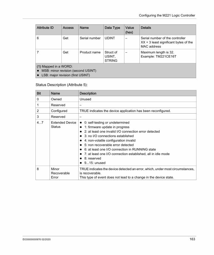
Configuring the M221 Logic Controller
Status Description (Attribute 5):
6 Get Serial number UDINT – Serial number of the controllerXX + 3 least significant bytes of the MAC address
7 Get Product name Struct of USINT, STRING
– Maximum length is 32. Example: TM221CE16T
Bit Name Description0 Owned Unused1 Reserved –2 Configured TRUE indicates the device application has been reconfigured.3 Reserved –4...7 Extended Device
Status 0: self-testing or undetermined 1: firmware update in progress 2: at least one invalid I/O connection error detected 3: no I/O connections established 4: non-volatile configuration invalid 5: non recoverable error detected 6: at least one I/O connection in RUNNING state 7: at least one I/O connection established, all in idle mode 8: reserved 9...15: unused
8 Minor Recoverable Error
TRUE indicates the device detected an error, which, under most circumstances, is recoverable.This type of event does not lead to a change in the device state.
Attribute ID Access Name Data Type Value (hex)
Details
(1) Mapped in a WORD: MSB: minor revision (second USINT) LSB: major revision (first USINT)
EIO0000000976 02/2020 163

Configuring the M221 Logic Controller
Message Router Object (Class ID = 02 hex)The following table describes the class attributes of the Message Router Object (Instance 0):
NOTE: Use instance 0 to read the Class Attributes information.
9 Minor Unrecoverable Error
TRUE indicates the device detected an error, which, under most circumstances, is not recoverable.This type of event does not lead to a change in the device state.
10 Major Recoverable Error
TRUE indicates the device detected an error, which requires the device to report an exception and enter into the HALT state.This type of event leads to a change in the device state, but, under most circumstances, is recoverable.
11 Major Unrecoverable Error
TRUE indicates the device detected an error, which requires the device to report an exception and enter into the HALT state.This type of event leads to a change in the device state, but, under most circumstances is not recoverable.
12...15 Reserved –
Bit Name Description
Attribute ID Access Name Data Type Value (hex)
Details
1 Get Revision UINT 01 Implementation revision of the Message Router Object
2 Get Max Instances
UINT 01 The largest instance number
3 Get Number of Instance
UINT 01 The number of object instances
4 Get Optional Instance Attribute List
Struct of UINT, UINT [ ]
– The first 2 bytes contain the number of optional instance attributes. Each following pair of bytes represents the number of other optional instance attributes (from 100 to 119).
5 Get Optional Service List
UINT 00 The number and list of any implemented optional services attribute (0: no optional services implemented)
6 Get Max Class Attribute
UINT 07 The largest class attributes value
7 Get Max Instance Attribute
UINT 77 The largest instance attributes value
164 EIO0000000976 02/2020

Configuring the M221 Logic Controller
The following table describes the Class Services:
The following table describes the Instance Services (Instance 1):
The following table describes the Instance attributes:
Service Code (hex) Name Description01 Get Attribute All Returns the value of all class attributes0E Get Attribute Single Returns the value of the specified attribute
Service Code (hex) Name Description01 Get Attribute All Returns the value of all class attributes0E Get Attribute Single Returns the value of the specified attribute
Attribute ID Access Name Data Type Value (hex)
Description
1 Get Implemented Object List
Struct of UINT, UINT [ ]
– Implemented Object list. The first 2 bytes contain the number of implemented objects. Each following pair of bytes represents another implemented class number. This list contains the following objects: 01: Identity 02: Message Router 04: Assembly 06: Connection Manager F5: TCP/IP F6: Ethernet Link
2 Get Number available UINT 08 Maximum number of concurrent CIP (Class 1 or Class 3) connections supported
100 Get Total incoming Class1 packets received during the last second
UINT – Total number of incoming packets received for all implicit (Class 1) connections during the last second
101 Get Total outgoing Class1 packets sent during the last second
UINT – Total number of outgoing packets sent for all implicit (Class 1) connections during the last second
EIO0000000976 02/2020 165

Configuring the M221 Logic Controller
102 Get Total incoming Class3 packets received during the last second
UINT – Total number of incoming packets received for all explicit (Class 3) connections during the last second
103 Get Total outgoing Class3 packets sent during the last second
UDINT – Total number of outgoing packets sent for all explicit (Class 3) connections during the last second
104 Get Total incoming unconnected packets received during the last second
UINT – Total number of incoming unconnected packets received during the last second
105 Get Total outgoing unconnected packets sent during the last second
UINT – Total number of outgoing unconnected packets sent during the last second
106 Get Total incoming EtherNet/IP packets received during the last second
UINT – Total unconnected Class 1 or Class 3 packets received during the last second
107 Get Total outgoing EtherNet/IP packets sent during the last second
UINT – Total unconnected Class 1 or Class 3 packets sent during the last second
108 Get Total incoming Class1 packets received
UINT – Total number of incoming packets received for all implicit (Class 1) connections
109 Get Total outgoing Class1 packets sent
UINT – Total number of outgoing packets sent for all implicit (Class 1) connections
110 Get Total incoming Class3 packets received
UINT – Total number of incoming packets received for all explicit (Class 3) connections. This number includes the packets that would be returned if an error had been detected (listed in the next two rows).
111 Get Total incoming Class3 packets Invalid Parameter Value
UINT – Total number of incoming Class 3 packets that targeted an unsupported service/class/instance/attribute/member
Attribute ID Access Name Data Type Value (hex)
Description
166 EIO0000000976 02/2020

Configuring the M221 Logic Controller
Assembly Object (Class ID = 04 hex)The following table describes the class attributes of the Assembly Object (Instance 0):
112 Get Total incoming Class3 packets Invalid Format
UINT – Total number of incoming Class 3 packets that had an invalid format
113 Get Total outgoing Class3 packets sent
UINT – Total number of packets sent for all explicit (Class 3) connections
114 Get Total incoming unconnected packets received
UINT – Total number of incoming unconnected packets. This number includes the packets that would be returned if an error had been detected (listed in the next two rows).
115 Get Total incoming unconnected packets Invalid Parameter Value
UINT – Total number of incoming unconnected packets that targeted an unsupported service/class/instance/attribute/member
116 Get Total incoming unconnected packets Invalid Format
UINT – Total number of incoming unconnected packets that had an invalid format
117 Get Total outgoing unconnected packets sent
UINT – Total number of all unconnected packets sent
118 Get Total incoming EtherNet/IP packets
UINT – Total number of unconnected (Class 1) or Class 3 packets received
119 Get Total outgoing EtherNet/IP packets
UINT – Total number of unconnected (Class 1) or Class 3 packets sent
Attribute ID Access Name Data Type Value (hex)
Description
Attribute ID Access Name Data Type Value (hex)
Details
1 Get Revision UINT 02 Implementation revision of the Assembly Object
2 Get Max Instances UINT – The largest instance number of created objects of this class.Example: If input instances = 200, output instances = 100, this attribute returns 200.
EIO0000000976 02/2020 167

Configuring the M221 Logic Controller
The following table describes the Class Services:
The following table describes the Instance Services:
Instances SupportedOutput means OUTPUT from Originator controller (= %IWE for the M221 Logic Controller).Input means INPUT from Originator controller (= %QWE for the M221 Logic Controller).The controller supports 2 Assemblies:
3 Get Number of Instances UINT 02 The number of object instances4 Get Optional Instance
Attribute ListStruct of:UINTUINT [ ]
– The first 2 bytes contain the number of optional instance attributes. Each following pair of bytes represents the number of other optional instance attributes.
5 Get Optional Service List UINT 00 The number and list of any implemented optional services attribute (0: no optional services implemented)
6 Get Max Class Attribute UINT 07 The largest class attributes value
7 Get Max Instance Attribute UINT 04 The largest instance attributes value
Service Code (hex) Name Description0E Get Attribute Single Returns the value of the specified attribute
Service Code (hex) Name Description0E Get Attribute Single Returns the value of the specified attribute10 Set Attribute Single Modifies the value of the specified attribute18 Get Member Reads a member of an Assembly object instance19 Set Member Modifies a member of an Assembly object instance
Name Instance Data SizeInput Assembly (EtherNet/IP) (%QWE)
Configurable from 1...255 1...20 words
Output Assembly (EtherNet/IP) (%IWE)
Configurable from 1...255 1...20 words
Attribute ID Access Name Data Type Value (hex)
Details
168 EIO0000000976 02/2020

Configuring the M221 Logic Controller
NOTE: The Assembly object binds together the attributes of multiple objects so that information sent to or received from each object can be communicated over a single connection. Assembly objects are static.The assemblies in use can be modified through the parameter access of the network configuration tool (RSNetWorx). You must perform a power cycle of the logic controller to register a new assembly assignment.The following table describes the Instance attributes:
Member list content:
EPATH is:
Attribute ID Access Name Data Type Value Description1 Get Number of Member
Object ListUINT 1...20 Number of members for this
assembly2 Get Member List ARRAY of
Struct– Array of 1 structure where
each structure represents one member
3 Get/Set Instance Data ARRAY of Byte
– Data Set service only available for Controller output
4 Get Instance Data Size UINT 2...40 Size of data in bytes
Name Data Type Value Type of ResetMember data size UINT 4...40 Member data size in bitsMember path size UINT 6 Size of the EPATH (see table below)Member path EPATH – EPATH to the Member
Word Value (hex) Semantic0 2004 Class 41 24xx Instance xx, where xx is the instance value (for example: 2464 hex = instance
100)2 xxxx See the Common Industrial Protocol Specification Volume 1 - Appendix C for
the format of this field
EIO0000000976 02/2020 169

Configuring the M221 Logic Controller
Connection Manager Object (Class ID = 06 hex)The following table describes the class attributes of the Assembly Object (Instance 0):
Attribute ID Access Name Data Type Value (hex)
Details
1 Get Revision UINT 01 Implementation revision of the Connection Manager Object
2 Get Max Instances
UINT 01 The largest instance number
3 Get Number of Instances
UINT 01 The number of object instances
4 Get Optional Instance Attribute List
Struct of:UINTUINT [ ]
– The number and list of the optional attributes. The first word contains the number of attributes to follow and each following word contains another attribute code.Following optional attributes include: Total number of incoming connection
open requests The number of requests rejected
because of the non-conforming format of the Forward Open
The number of requests rejected because of insufficient resources
The number of requests rejected because of the parameter value sent with the Forward Open
The number of Forward Close requests received
The number of Forward Close requests that had an invalid format
The number of Forward Close requests that could not be matched to an active connection
The number of connections that have timed out because the other side stopped producing, or a network disconnection occurred
6 Get Max Class Attribute
UINT 07 The largest class attributes value
7 Get Max Instance Attribute
UINT 08 The largest instance attributes value
170 EIO0000000976 02/2020

Configuring the M221 Logic Controller
The following table describes the Class Services:
The following table describes the Instance Services:
The following table describes the Instance attributes (Instance 1):
Service Code (hex) Name Description01 Get Attribute All Returns the value of all class attributes0E Get Attribute Single Returns the value of the specified attribute
Service Code (hex) Name Description01 Get Attribute All Returns the value of all instance attributes0E Get Attribute Single Returns the value of the specified attribute4E Forward Close Closes an existing connection52 Unconnected Send Sends a multi-hop unconnected request54 Forward Open Opens a new connection
Attribute ID Access Name Data Type Value Description1 Get Open Requests UINT – Number of Forward Open service
requests received 2 Get Open Format Rejects UINT – Number of Forward Open service
requests which were rejected due to invalid format
3 Get Open Resource Rejects
UINT – Number of Forward Open service requests which were rejected due to lack of resources
4 Get Open Other Rejects UINT – Number of Forward Open service requests which were rejected for reasons other than invalid format or lack of resources
5 Get Close Requests UINT – Number of Forward Close service requests received
6 Get Close Format Requests
UINT – Number of Forward Close service requests which were rejected due to invalid format
7 Get Close Other Requests
UINT – Number of Forward Close service requests which were rejected for reasons other than invalid format
8 Get Connection Timeouts UINT – Total number of connection timeouts that have occurred in connections controlled by this Connection Manager
EIO0000000976 02/2020 171

Configuring the M221 Logic Controller
TCP/IP Interface Object (Class ID = F5 hex)This object provides the mechanism to configure a TCP/IP network interface device.The following table describes the class attributes of the TCP/IP Interface Object (Instance 0):
The following table describes the Class Services:
Instance CodesOnly instance 1 is supported.The following table describes the Instance Services:
Attribute ID Access Name Data Type Value (hex)
Details
1 Get Revision UINT 02 Implementation revision of the TCP/IP Interface Object
2 Get Max Instances UINT 01 The largest instance number3 Get Number of Instance UINT 01 The number of object
instances6 Get Max Class Attribute UINT 07 The largest class attributes
value7 Get Max Instance Attribute UINT 06 The largest instance attributes
value
Service Code (hex) Name Description01 Get Attribute All Returns the value of all class attributes0E Get Attribute Single Returns the value of the specified attribute
Service Code (hex) Name Description01 Get Attribute All Returns the value of all instance attributes0E Get Attribute Single Returns the value of the specified instance attribute
172 EIO0000000976 02/2020

Configuring the M221 Logic Controller
The following table describes the Instance Attributes (Instance 1):
Attribute ID Access Name Data Type Value Description1 Get Status DWORD Bit level 0: The interface configuration
attribute has not been configured. 1: The interface configuration
contains a valid configuration.All other bits are reserved and set to 0.
2 Get Configuration Capability
DWORD Bit level 0: BOOTP Client 2: DHCP Client
All other bits are reserved and set to 0.
3 Get Configuration DWORD Bit level 0: The interface configuration is valid.
1: The interface configuration is obtained with BOOTP.
2: The interface configuration is obtained with DHCP.
3: Reserved 4: DNS Enable
All other bits are reserved and set to 0.
4 Get Physical Link UINT Path size Number of 16-bit words in the Path element
Padded EPATH
Path Logical segments identifying the physical link object. The path is restricted to one logical class segment and one logical instance segment. The maximum size is 12 bytes.
EIO0000000976 02/2020 173

Configuring the M221 Logic Controller
5 Get Interface configuration
UDINT IP Address Hexadecimal formatExample: 55 DD DD DE = 85.221.221.222
UDINT Network Mask
Hexadecimal formatExample: FF 0 0 0 = 255.0.0.0
UDINT Gateway Address
Hexadecimal formatExample: 55 DD DD DE = 85.221.221.222
UDINT Primary Name
0: no primary name server address has been configured.
UDINT Secondary Name
0: no secondary name server address has been configured. Otherwise, the name server address shall be set to a valid Class A, B, or C address.
STRING Default Domain Name
ASCII characters. Maximum length is 16 characters. Padded to an even number of characters (padding not included in length).0: no Domain Name is configured
6 Get Host Name UINT – Host name lengthSTRING – ASCII characters. Maximum length is
64 characters. Padded to an even number of characters (padding not included in length). 0: no Host Name is configured
Attribute ID Access Name Data Type Value Description
174 EIO0000000976 02/2020

Configuring the M221 Logic Controller
Ethernet Link Object (Class ID = F6 hex)This object maintains link specific counters and status information for an Ethernet 802.3 communications interface.The following table describes the class attributes of the Ethernet Link Object (Instance 0):
The following table describes the Class Services:
Instance CodesOnly instance 1 is supported.The following table describes the Instance Services:
Attribute ID Access Name Data Type Value (hex)
Details
1 Get Revision UINT 03 Implementation revision of the Ethernet Link Object
2 Get Max Instances UINT 01 The largest instance number3 Get Number of Instances UINT 01 The number of object
instances6 Get Max Class Attribute UINT 07 The largest class attributes
value7 Get Max Instance Attribute UINT 03 The largest instance attribute
value
Service Code (hex) Name Description01 Get Attribute All Returns the value of all class attributes0E Get Attribute Single Returns the value of the specified attribute
Service Code (hex) Name Description01 Get Attribute All Returns the value of all instance attributes0E Get Attribute Single Returns the value of the specified instance attribute
EIO0000000976 02/2020 175

Configuring the M221 Logic Controller
The following table describes the Instance Attributes (Instance 1):
Attribute ID Access Name Data Type Value Description1 Get Interface Speed UDINT – Speed in Mbps (10 or 100)2 Get Interface Flags DWORD Bit level 0: link status
1: half/full duplex 2...4: negotiation status 5: manual setting / requires
reset 6: local hardware error detected
All other bits are reserved and set to 0.
3 Get Physical Address
ARRAY of 6 USINT
– This array contains the MAC address of the product.Format: XX-XX-XX-XX-XX-XX
176 EIO0000000976 02/2020
Configuring the M221 Logic Controller
Configuring Serial Lines
IntroductionThe M221 Logic Controller references are equipped with at least 1 serial line. The controller references without the Ethernet feature support 2 serial lines: SL1 (serial line) SL2 (serial line)Each serial line can be configured for one of the following protocols: Modbus (RTU or ASCII) (see page 181). Serial lines are configured for the Modbus RTU
protocol by default. ASCII (see page 181) Modbus Serial IOScanner (see page 186). Only one instance can be configured: if configured
on one serial line, it cannot be used on the other serial line. NOTE: Care must be taken when both the Modbus Serial IOScanner and Message (%MSG) function blocks (see EcoStruxure Machine Expert - Basic, Generic Functions Library Guide) are used in your application, as this can lead to the cancellation of on-going IOScannner communication.The application must be configured with a functional level (see EcoStruxure Machine Expert - Basic, Operating Guide) of at least Level 5.0 to support the Modbus Serial IOScanner.
NOTE: The TMH2GDB Remote Graphic Display (see page 185) protocol can only be configured on SL1.
Modem SupportA modem connection allows you to: Remotely access the controller for the purpose of programming and/or monitoring. In this case,
a local modem must be connected to the PC running the EcoStruxure Machine Expert - Basic software, and a modem connection must be configured (see EcoStruxure Machine Expert - Basic, Operating Guide).
Perform data exchanges between controllers using the Modbus protocol. Send or receive messages with any device using the Send Receive Message function block. Send or receive SMS to or from mobile phone or other devices able to send or receive SMS
messages.Serial lines support the following features to simplify modem connections: An initialization (Init) command to send an initial configuration to the modem. This command is
automatically sent by the controller after an application download or at power on. System bit %S105 to be able to send the Init command to the modem again. System word %SW167 to provide the status of the Init command operation.
EIO0000000976 02/2020 177

Configuring the M221 Logic Controller
Serial Line ConfigurationThis table describes how to configure the serial line:
Step Action1 Click the SL1 (Serial line) or SL2 (Serial line) node in the hardware tree to display the serial line
configuration.
2 Select the Protocol to use on the serial line.For detailed information on the serial line configuration parameters, refer to the following table.
3 Click Apply.4 In the hardware tree select the Modbus, ASCII, Display, or Modbus Serial IOScanner node that
appears below the SL1 (Serial Line) or SL2 (Serial Line) node.
178 EIO0000000976 02/2020

Configuring the M221 Logic Controller
This table describes protocol and serial line settings of the serial line:
Parameter Editable Value Default Value DescriptionProtocol SettingsProtocol Yes Modbus
ASCIITMH2GDBModbus Serial IOScanner
Modbus Select a protocol from the drop-down list.
NOTE: When using an SR2MOD03 modem and the Send Receive SMS function block, select the ASCII protocol.
Serial Line SettingsBaud rate Yes 1200
240048009600192003840057600115200
19200 Allows you to select the data transmission rate (bits per second) from the drop-down list.
Parity Yes NoneEvenOdd
Even Allows you to select the parity of the transmitted data for error detection.Parity is a method of error detection in transmission.When parity is used with a serial port, an extra data bit is sent with each data character, arranged so that the number of bits set to 1 in each character, including the parity bit, is always odd or always even.If a byte is received with an incorrect number of bits set to 1, the byte is invalid.
Data bits Yes(only for the ASCII protocol
78
8 Allows you to select the data bit from the drop-down list.The number of data bits in each character can be 7 (for true ASCII) or 8.
Stop bits Yes 12
1 Allows you to select the stop bit from the drop-down list.Stop bit is a bit indicating the end of a byte of data. For electronic devices usually 1 stop bit is used. For slow devices like electromechanical teleprinters, 2 stop bits are used.
EIO0000000976 02/2020 179

Configuring the M221 Logic Controller
Physical medium Yes RS-485RS-232
RS-485 Allows you to select the physical medium for communication.You can select either RS-485 or RS-232 medium. For the embedded serial line 2, only RS-485 medium is available.A physical medium in data communications is the transmission path over which a signal propagates. It is an interface for interconnection of devices with the logic controller.
NOTE: When using an SR2MOD03, select the RS-232 option.
Polarization Yes (for cartridges only)No (for the controller)
YesNo
No Polarization resistors are integrated in cartridge modules.For the controller, this parameter is disabled and for the cartridges, this parameter allows you to switch on or off polarization.
Parameter Editable Value Default Value Description
180 EIO0000000976 02/2020

Configuring the M221 Logic Controller
Configuring Modbus and ASCII Protocols
Device Settings for Modbus and ASCII ProtocolsThis table describes the parameters when the Modbus or ASCII protocol is selected:
Parameter Editable Value Default Value DescriptionDevice SettingsDevice Yes None
Generic ModemSR2MOD01SR2MOD03
None Select a device from the drop-down list.Select SR2MOD03 to use the %SEND_RECV_SMS function block.
Init command Yes - - The Init command is a set of Hayes commands sent to the modem connected on the serial line. It is an ASCII string limited to 128 characters. The logic controller uses this string to configure and verify the modem.The Init command is sent to the modem: At power on If the %S105 system bit is set to 1.
%SW167 provides the status of the initialization command sent to the modem.A default Init command is used by EcoStruxure Machine Expert - Basic for SR2MOD03 modem. For more information, refer to the SR2MOD02 and SR2MOD03 Wireless Modem User Guide.
NOTE: To use the SMS function block, change the default Init command to: AT&F;E0;S0=2;Q0;V1;+WIND=0;+CBST=0,0,1;&W;+CNMI=0,2,0,0,0;+CSAS;+CMGF=0;+CMEE=1 (see Recv_SMS Function Block (see EcoStruxure Machine Expert - Basic, Generic Functions Library Guide)).
EIO0000000976 02/2020 181

Configuring the M221 Logic Controller
Configuring the Modem Init CommandThe Init command is a set of Hayes commands sent to initialize a modem. The default Init command provided by EcoStruxure Machine Expert - Basic configuration screen is to be used with a modem to match with the default serial line configuration for remote access, exchanges between controllers or sending/receiving messages.Use a PC terminal software if you need to adapt the Init command.
SR2MOD01 Hayes CommandThe default Init command provided by EcoStruxure Machine Expert - Basic is: ate0\n0\v1&d0&k0s0=1s89=0$EB0#p0$sb19200n0s28=1s37=13&w0
SR2MOD03 Hayes CommandThe default Init command provided by EcoStruxure Machine Expert - Basic is: AT&F;E0;S0=2;Q0;V1;+WIND=0;+CBST=0,0,1;&W;+CMGF=1;+CNMI=0,2,0,0,0;+CSASTo send or receive SMS, the command must be modified to: AT&F;E0;S0=2;Q0;V1;+WIND=0;+CBST=0,0,1;&W;+CNMI=0,2,0,0,0;+CSAS;+CMGF=0;+CMEE=1
Protocol Settings for ModbusThis table describes the parameters when the Modbus protocol is selected:
Parameter Editable Value Default Value DescriptionTransmission mode Yes RTU
ASCIIRTU Allows you to select the protocol
transmission mode for communication from the drop-down list.Select ASCII to use the %SEND_RECV_SMS function block.Protocol advanced parameters are displayed based on the selected protocol.
Addressing Yes SlaveMaster
Slave Allows you to select the addressing mode. You can only select either of the Slave or Master addressing. Selecting any of the addressing modes clears the present one.A device configured as a slave can send Modbus requests.
182 EIO0000000976 02/2020

Configuring the M221 Logic Controller
Protocol Settings for ASCIIThis table describes the parameters when the ASCII protocol is selected:
Address [1...247] Yes 1...247 1 Allows you to specify the address ID of the slave.
NOTE: This field is displayed only for the addressing of the slave. For master, this field does not appear on the screen.
Response timeout (x 100 ms)
Yes 0...255 10 Defines the maximum time that the controller waits for a response before terminating the exchange in error. Enter 0 to disable the timeout.
Time between frames (ms)
Yes 1...255 10 The period of time between frames (corresponds to inter-frame delay used in other products).
NOTE: The value is subject to adjustment to conform to Modbus standard 3.5 character time delay.
Parameter Editable Value Default Value Description
Parameter Editable Value Default Value DescriptionResponse timeout (x 100 ms)
Yes 0...255 10 Defines the maximum time that the controller waits for a response before terminating the exchange in error. Enter 0 to disable the timeout.
NOTE: When using an SR2MOD03 and the function block SMS, enter 0 to disable the timeout.
Stop conditionFrame length received Yes (only if the
check box is selected)
1...255 0 (if check box is not selected)1 (if check box is selected)
Allows you to specify the length of the received frame.
NOTE: You can configure only one parameter for stop condition that is either Frame length received or Frame received timeout (ms).
Frame received timeout (ms)
Yes (only if the check box is selected)
1...255 0 (if check box is not selected)10 (if check box is selected)
Allows you to specify the timeout duration for the received frame.
NOTE: When using an SR2MOD03 and the function block SMS, select the checkbox and enter 200.
EIO0000000976 02/2020 183

Configuring the M221 Logic Controller
Frame structureStart character Yes (only if the
check box is selected)
1...255 0 (if check box is not selected)58 (if check box is selected)
Allows you to specify the start character of the frame.The ASCII character corresponding to the start character value is displayed on right-hand side of the value field.
First end character Yes 1...255 0 (if check box is not selected)10 (if check box is selected)
Allows you to specify the first end character of the frame.
NOTE: To be able to disable the First end character, configure at least one stop condition parameter.The ASCII character corresponding to the first end character value is displayed on right-hand side of the value field.
Second end character Yes (only if the check box is selected)
1...255 0 (if check box is not selected)10 (if check box is selected)
Allows you to specify the second end character of the frame.
NOTE: This field is disabled when the disabled First end character is disabled.The ASCII character corresponding to the second end character value is displayed on right-hand side of the value field.
Send frame characters
Yes TRUE/FALSE FALSE Allows you to enable or disable the automatic addition of start, first end, and second end characters (when defined) in the frames sent.
Parameter Editable Value Default Value Description
184 EIO0000000976 02/2020

Configuring the M221 Logic Controller
Configuring the TMH2GDB Remote Graphic Display
Protocol Settings for DisplayThis table describes the parameters when the Display protocol is selected:
Parameter Editable Value Default Value DescriptionTime between frames (ms)
Yes 1...255 10 The period of time between frames (corresponds to inter-frame delay used in other products).
NOTE: The value is subject to adjustment to conform to Modbus standard 3.5 character time delay.
EIO0000000976 02/2020 185

Configuring the M221 Logic Controller
Configuring Modbus Serial IOScanner
DescriptionOnly one instance of IOScanner can be defined: if you configure it on a Ethernet port, you cannot configure it on an serial port. Refer to Configuring Modbus TCP IOScanner (see page 146).The maximum number of TCP and Serial IOScanner objects is: 128, if the Functional Level < 6.0. 512, if the Functional Level ≥ 6.0.
Protocol SettingsThis table describes the parameters when the Modbus Serial IOScanner protocol is selected:
Parameter Editable Value Default Value DescriptionTransmission mode Yes RTU
ASCIIRTU Select the protocol transmission
mode for communication from the drop-down list.
Response timeout (x 100 ms) Yes 0...255 10 Defines the maximum time that the controller waits for a response before terminating the exchange in error. Enter 0 to disable the timeout.
Time between frames (ms) Yes 1...255 10 The period of time between frames (corresponds to inter-frame delay used in other products).
NOTE: The value is subject to adjustment to conform to Modbus standard 3.5 character time delay.
186 EIO0000000976 02/2020

Configuring the M221 Logic Controller
Adding a Device on the Modbus Serial IOScanner
IntroductionThis section describes how to add devices to be scanned by the Modbus Serial IOScanner.You can add up to 16 Modbus slave devices. EcoStruxure Machine Expert - Basic is supplied with a number of predefined device types. Predefined device types have predefined initialization requests and preconfigured channels to facilitate integration of the devices in the network.A generic slave device is also provided, for which initialization requests and channels must be configured.
Adding a Device on the Modbus Serial IOScannerTo add a device on the Modbus Serial IOScanner:
Device SettingsThis table describes the parameters when the Modbus Serial IOScanner protocol is selected:
Step Action1 Choose either:
Drive and select one of the supported device types from the dropdown list. Others and select the device type from the dropdown list.
If you cannot find your device type in either list, select Generic device and configure it.2 Click Add.3 Configure the device as described in Device Settings (see page 187).4 Click Apply.
Parameter Editable Value Default Value DescriptionID No 0...15 0 Unique device identifier assigned by
EcoStruxure Machine Expert - Basic.
Name Yes 1...32 charactersThe device name must be unique.
Device x(1) Specify a unique name for the device.
Address No –%DRVn (1) (2)
–%DRV0
%DRVn is used to configure the device in the application using Drive function blocks (see page 334).
(1) x and n are integers incremented each time a device or a drive device is added.(2) Only if Drive is selected as the device type.
EIO0000000976 02/2020 187

Configuring the M221 Logic Controller
Type No Type of the device – The device type is not editable. To change the device type, you must remove the device from the list (by right-clicking and choosing Delete), then add the correct device type.
Slave address Yes 1...247 1 Address used to identify the device within the network. Duplicate slave addresses are allowed.
Response timeout (x 100 ms)
Yes 0...255 10 The timeout (in milliseconds) used in data exchanges with the device. This value can be adapted individually to the device and overrides the Response timeout set for the master in the Protocol Settings.
Reset variable Yes %Mn – Specify the address of the memory bit to use to reset the device (re-send the initialization requests). When the specified memory bit is set to 1 by the application, the device is reset.
Init. requests Yes - Click to display the Initialization request assistant window (see page 189).
Channels Yes - Click to display the Channel assistant window (see page 191).
Parameter Editable Value Default Value Description
(1) x and n are integers incremented each time a device or a drive device is added.(2) Only if Drive is selected as the device type.
188 EIO0000000976 02/2020

Configuring the M221 Logic Controller
Configuring Initialization RequestsInitialization requests are device-specific commands sent by the Modbus TCP IOScanner or Modbus Serial IOScanner to initialize a slave device. The Modbus TCP IOScanner or Modbus Serial IOScanner does not start cyclic data exchange with the device until all its initialization requests have been acknowledged by the device. During the initialization phase, network objects are not updated.Up to 20 initialization requests can be defined for each slave device.The Initialization request assistant window presents the defined initialization requests:
Preconfigured initialization requests are displayed with a lock symbol and a gray background. Some parameters cannot be modified for predefined initialization requests.According to the device type that you selected, some initialization requests may be configured.
EIO0000000976 02/2020 189

Configuring the M221 Logic Controller
This table describes the properties of initialization requests:
Click Add to create new initialization requests.Select an entry then use the up arrow and down arrow buttons to change the order in which the initialization requests are sent to the device.When the initialization requests have been defined, click OK to save the configuration and close the Initialization request assistant.
Parameter Editable Value Default Value DescriptionID No 0...19 0 Unique initialization request identifier.Message type Yes, if
initialization request is not predefined.
See Supported Modbus Function Codes (see page 197)
Mbs 0x05 - Write single bit (coil)
Select the Modbus function code for the type of exchange to use for this initialization request.
NOTE: If configuring a generic device that does not support the default Mbs 0x05 - Write single bit (coil) request type, you must replace the default value with a supported request type.
Offset Yes, if initialization request is not predefined.
0...65535 0 Offset of the first register to initialize.
Length Yes, if initialization request is not predefined.
1 for Mbs 0x05 - Write single bit (coil)1 for Mbs 0x06 - Write single word (register)128 for Mbs 0x0F - Write multiple bits (coils)123 for Mbs 0x10 - Write multiple words (reg.)
1 Number of objects (memory words or bits) to be initialized. For example, if writing multiple words with Offset = 2 and Length = 3, %MW2, %MW3, and %MW4 are initialized.
Initialization value
Yes, if initialization request is not predefined.
0...65535 if memory words (registers) are being initialized0...1 if memory bits (coils) are being initialized
0 Value to initialize the targeted registers with.
Comment Yes, if initialization request is not predefined.
- Empty Optionally, type a comment to associate with this request.
190 EIO0000000976 02/2020

Configuring the M221 Logic Controller
Channel AssistantUp to 10 channels can be defined for each slave device. Each channel represents a single Modbus request. NOTE: The number of objects defined (items of data read and written) is validated when you click Apply on the properties window.The Channel assistant window lists the defined channels:
Preconfigured channels are displayed with a lock symbol and a gray background. Some parameters cannot be modified for predefined channels.
EIO0000000976 02/2020 191

Configuring the M221 Logic Controller
This table describes the properties of channels:
Click Add to create a new channel.When the channels have been defined, click OK to save the configuration and close the Channel assistant.
Parameter Editable Value Default Value DescriptionID No 0...19 0 Unique initialization identifier.Name Yes 0...32 characters Device_channel0 Double-click to edit the name of the
channel.Configuration Yes - Click to display the Channel Assistant
window (see page 154).Message type No - - The Modbus function code that was
selected in the Channel Assistant window (see page 154).
Trigger No - - The trigger type and cycle time that was selected in the Channel Assistant window (see page 154).
R Offset No - - The READ object offset that was selected in the Channel Assistant window (see page 154).
R Length No - - The READ object length that was selected in the Channel Assistant window (see page 154).
Error management
No - - The error management policy that was selected in the Channel Assistant window (see page 154).
W Offset No - - The WRITE object offset that was selected in the Channel Assistant window (see page 154).
W Length No - - The WRITE object length that was selected in the Channel Assistant window (see page 154).
Comment Yes - Empty Optionally, type a comment to associate with this channel.
192 EIO0000000976 02/2020

Configuring the M221 Logic Controller
Configuring ChannelsUse the Channel assistant window to configure channels.The following example shows a channel configured for a Read/Write Multiple Words request (Modbus function code 23). It reads one word from the register with offset 16#0C21 and writes two words to the register with offset 16#0C20. This request is executed when there is a rising edge of the defined Trigger (see table below):
EIO0000000976 02/2020 193

Configuring the M221 Logic Controller
This table describes the properties of channels:
Parameter Editable Value Default Value DescriptionName Yes 0...32 characters Device 0_Channel0 Enter a name for the channel.Message type Yes See Supported
Modbus Function Codes (see page 197)
Mbs 0x17 - Read/Write mult. words (reg.)
Select the Modbus function code for the type of exchange to use on this channel.
Trigger Yes CyclicRising edge
Cyclic Choose the trigger type for the data exchange: Cyclic: The request is triggered
with the frequency defined in the Cycle Time (x 10 ms) field
Rising edge: The request is triggered upon detection of a rising edge of a memory bit. Specify the address of the Memory bit to use.
Cycle time (x 10 ms)(If Cyclic is selected)
Yes 1...6000 20 Specify the periodic trigger cycle time, in units of 10 ms.
Memory bit(If Rising edge is selected)
Yes %Mn - Specify a memory bit address, for example, %M8. The data exchange is triggered when a rising edge of this memory bit is detected.
Comment Yes - Empty Optionally, type a comment to describe the purpose of the channel.
194 EIO0000000976 02/2020

Configuring the M221 Logic Controller
Click OK to complete channel configuration.
READ objectsOffset Yes 0...65535 0 Address of the first memory word
(register) or bit (coil) to read.Length Yes See Supported
Modbus Function Codes (see page 197) for maximum length
- Number of memory words (registers) or bits (coils) to read.
Error management
Yes Set to zeroRetain last value
Set to zero Specify how to manage the situation when data can no longer be read from the device: Select Set to zero to set the last
data values received to zero. Select Retain last value to keep
the last data values received.WRITE objectsOffset Yes 0...65535 0 Address of the first memory word
(register) or bit (coil) to write.Length Yes See Supported
Modbus Function Codes (see page 197) for maximum length
- Number of memory words (registers) or bits (coils) to write.
Parameter Editable Value Default Value Description
EIO0000000976 02/2020 195

Configuring the M221 Logic Controller
Supported Modbus Function Codes
PresentationThis section lists the supported Modbus function codes and their effect on controller memory variables for: Modbus Serial (see page 196) Modbus Serial IOScanner (see page 197) Modbus TCP (see page 197) Modbus TCP IOScanner (see page 197)
Modbus SerialThe following Modbus requests are supported:
NOTE: The impact of Modbus function codes used by a master M221 Logic Controller depends on the slave device type. In the major types of slave device: Internal bit means %M Input bit means %I Internal register means %MW Input register means %IWDepending on the type of slave and the slave address, an internal bit should be a %M or %Q; an input bit should be a %I or %S, an input register should be a %IW or a %SW and an internal register should be a %MW or a %QW. For more details, refer to the documentation of the slave device.
Supported Modbus Function Code Dec (Hex)
Supported Sub-Function Code
Description
1 (1 hex) or 2 (2 hex) – Read multiple internal bits %M3 (3 hex) or 4 (4 hex) – Read multiple internal registers %MW5 (5 hex) – Write single internal bit %M6 (6 hex) – Write single internal register %MW8 (8 hex) 0 (0 hex), 10
(0A hex)...18 (12 hex)Diagnostics
15 (0F hex) – Write multiple internal bits %M16 (10 hex) – Write multiple internal registers %MW23 (17 hex) – Read/write multiple internal registers %MW43 (2B hex) 14 (0E hex) Read device identification (regular service)
196 EIO0000000976 02/2020

Configuring the M221 Logic Controller
Modbus Serial IOScanner and Modbus TCP IOScannerThis table lists the Modbus function codes supported by the Modbus Serial IOScanner and Modbus TCP IOScanner:
Modbus Mapping Table for Modbus TCPModbus TCP slave devices support a subset of the Modbus function codes. Function codes originating from a Modbus master with matching unit ID are directed to the Modbus mapping table and access network objects (%IWM and %QWM) of the controller. Refer to Modbus TCP Slave Device I/O Mapping Table (see page 147).
Function Code Dec (Hex)
Description Available For Configuration
Maximum Length (Bits)
1 (1 hex) Read multiple bits (coils) Channel 1282 (2 hex) Read multiple bits (discrete inputs) Channel 1283 (3 hex) Read multiple words (holding registers) Channel 1254 (4 hex) Read multiple words (input registers) Channel 1255 (5 hex) Write single bit (coil) Channel
Initialization Value (default message type for initialization values)
1
6 (6 hex) Write single word (register) ChannelInitialization Value
1
15 (0F hex) Write multiple bits (coils) ChannelInitialization Value
128
16 (10 hex) Write multiple words (registers) ChannelInitialization Value
123
23 (17 hex) Read/write multiple words (registers) Channel (default message type for channel configuration)
125 (read)121 (write)
EIO0000000976 02/2020 197

Configuring the M221 Logic Controller
SD Card
Section 3.5SD Card
IntroductionThe Modicon M221 Logic Controller allows file transfers with an SD card.This chapter describes how to manage Modicon M221 Logic Controller files with an SD card.You can use the SD card when you want to store data. Refer to Data Logging.
What Is in This Section?This section contains the following topics:
Topic PageFile Management Operations 199SD Card Supported File Types 201Clone Management 203Firmware Management 205Application Management 209Post Configuration Management 211Error Log Management 213Memory Management: Backing Up and Restoring Controller Memory 216
198 EIO0000000976 02/2020

Configuring the M221 Logic Controller
File Management Operations
IntroductionThe Modicon M221 Logic Controller allows the following types of file management with an SD card: Clone management (see page 203): back up the application, firmware, and post configuration
(if it exists) of the logic controller Firmware management (see page 205): download firmware directly to the logic controller, and
load firmware to the Remote Graphic Display Application management (see page 209): back up and restore the logic controller application,
or copy it to another logic controller of the same reference Post configuration management (see page 211): add, change, or delete the post configuration
file of the logic controller Error log management (see page 213): back up or delete the error log file of the logic controller Memory management (see page 216): Back up and restore memory objects of the controllerNOTE: Logic controller logic solving and services execution continues during file transfers. Certain commands require a power cycle of the logic controller. See the description of the
commands for more information. The Modicon M221 Logic Controller accepts only SD cards formatted in FAT or FAT32. With the use of the SD card, powerful operations can be automatically conducted affecting the behavior of your logic controller and resident application. Care must be taken when inserting an SD card into the controller; you must be aware of the affect that the contents of the SD card will have on your logic controller.NOTE: File management with SD card uses script files. These scripts can be automatically created with the Memory Management task (see EcoStruxure Machine Expert - Basic, Operating Guide).
WARNINGUNINTENDED EQUIPMENT OPERATION You must have operational knowledge of your machine or process before connecting an SD
card to your logic controller. Ensure that guards are in place so that any potential affect of the contents of the SD card will
not cause injury to personnel or damage to equipment.Failure to follow these instructions can result in death, serious injury, or equipment damage.
EIO0000000976 02/2020 199

Configuring the M221 Logic Controller
If you remove power to the device, or there is a power outage or communication interruption during the transfer of the application, your device may become inoperative. If a communication interruption or a power outage occurs, reattempt the transfer. If there is a power outage or communication interruption during a firmware update, or if an invalid firmware is used, your device will become inoperative. In this case, use a valid firmware and reattempt the firmware update.
NOTICEINOPERABLE EQUIPMENT Do not interrupt the transfer of the application program or a firmware change once the transfer
has begun. Re-initiate the transfer if the transfer is interrupted for any reason. Do not attempt to place the device (logic controller, motion controller, HMI controller or drive)
into service until the file transfer has completed successfully.Failure to follow these instructions can result in equipment damage.
200 EIO0000000976 02/2020

Configuring the M221 Logic Controller
SD Card Supported File Types
IntroductionThis table lists the file locations and types of file that can be managed:
Script File CommandsA script file is a text file stored in the root directory of the SD card containing commands to manage exchanges with the controller. Script files must be encoded in ANSI format.This table describes the supported script commands:
SD card folder Description Default file name/ Script file Script.cmd/ Script log Script.log/disp/ Remote Graphic Display firmware file TMH2GDB.mfw/sys/os Logic controller firmware file M221.mfw/TM3 TM3 analog expansion modules firmware TM3_Ana.mfw/usr/app Application file *.smbk/usr/cfg Post configuration file Machine.cfg/usr/mem Memory back up file Memories.csv/sys/log Detected error log file PlcLog.csv
Command DescriptionDownload Download a file from the SD card to the controller.Upload Upload files contained in controller memory to the SD
card.Delete Delete files contained in a controller.
EIO0000000976 02/2020 201

Configuring the M221 Logic Controller
Script File ExamplesDownload commands:Download "/usr/cfg"Download "/sys/os/M221.mfw"Download "/disp/TMH2GDB.mfw"Upload commands:Upload "/usr/app/*"Upload "/usr/cfg/Machine.cfg"Delete commands:Delete "/usr/app/*"Delete "/sys/log/PlcLog.csv"NOTE: Post configuration files specified in Upload or Delete commands must have the extension .cfg or .CFG.If no post configuration file is specified, or the specified file name does not exist, the default file name Machine.cfg is assumed.
Script LogA script.log file is automatically created in the SD card root directory after script operations. The status of the script operations can be verified reading this file.
202 EIO0000000976 02/2020

Configuring the M221 Logic Controller
Clone Management
CloningCloning allows you to automatically back up the application, firmware, and post configuration (if it exists) of the Modicon M221 Logic Controller to the SD card.The SD card can then be used to later restore the firmware, application, and post configuration (if it exists) to the logic controller, or copy them to another logic controller with the same reference.Before cloning a controller, the M221 Logic Controller verifies whether the application is copy-protected or not. For details, refer to Password Protecting an Application (see EcoStruxure Machine Expert - Basic, Operating Guide).NOTE: The SD card must be empty and correctly formatted to perform this procedure. The SD card name must be different from DATA, refer to Data Logging. The detected error log and data memory are not cloned. If the application is password-protected, the clone operation is blocked (the SD LED is flashing).
Creating a Clone SD CardThis procedure describes how to copy the application, firmware, and post configuration (if it exists) from the controller to an SD card:
Step Action1 Format an SD card on the PC.2 Insert the SD card into the controller.
Result: The clone operation starts automatically and the SD LED is illuminated.3 Wait until the end of the operation (until the SD LED is off or flashing).
If an error is detected, the SD LED flashes and the detected error is logged in Script.log file.
NOTE: The clone operation lasts 2 or 3 minutes. The clone operation has a low priority in order to minimize impact on the user logic and communication performance of the logic controller. Depending on the amount of free time in your program, the operation may require more time to complete if the logic controller is in RUNNING state compared to the STOPPED state.
4 Remove the SD card from the controller.
EIO0000000976 02/2020 203

Configuring the M221 Logic Controller
Restoring or Copying from a Clone SD CardThis procedure describes how to download the application, firmware, and post configuration (if it exists) stored in the SD card to your controller:
NOTE: Downloading a cloned application to the controller first removes the existing application from controller memory, regardless of any user access-rights that may be enabled in the target controller.
Step Action1 Remove power from the controller.2 Insert the SD card into the controller.3 Restore power to the controller.
Result: The clone operation is in progress.
NOTE: The SD LED is turned on during the operation.
4 Wait until the end of the operation (until the SD LED is off or flashing).If an error is detected, the SD and ERR LEDs flash and the detected error is logged in Script.log file.
5 Remove the SD card to restart the controller.
204 EIO0000000976 02/2020

Configuring the M221 Logic Controller
Firmware Management
OverviewYou can use an SD card to download firmware updates directly to the logic controller, a Remote Graphic Display, or TM3 analog expansion modules.Refer to Controller States and Behavior (see page 62) for information on the logic controller operating states and status of the LEDs.To perform firmware management, the SD card name must be different from DATA, refer to Data Logging.
Downloading Firmware to the ControllerThis table describes how to download a firmware to the logic controller using an SD card:
Step Action1 Remove power from the controller.2 Insert an empty SD card into the PC that is running EcoStruxure Machine Expert - Basic.3 Create a file called script.cmd in the SD card root directory.
4 Edit the file and insert the following command:Download "/sys/os"
5 Create the folder path \sys\os in the SD card root directory and copy the firmware file in the os folder:
NOTE: A firmware file example and the script are available in the folder Firmwares & PostConfiguration\M221\ of the EcoStruxure Machine Expert - Basic installation folder.The firmware file name for the M221 Logic Controller is M221.mfw.
6 Remove the SD card from the PC and insert it into the SD card slot of the logic controller.7 Restore power to the controller.
Result: Copying of the firmware file begins. During the operation, the SD system LED on the logic controller is illuminated.
NOTE: Avoid removing power from the logic controller while the operation is in progress.
8 Wait until the end of the operation (until the SD LED is off or flashing).If an error is detected, the SD and ERR LEDs flash and the detected error is logged in Script.log file.
9 Remove the SD card.10 Reconnect the USB programming cable to the logic controller and login to the logic controller with
the EcoStruxure Machine Expert - Basic software.
EIO0000000976 02/2020 205

Configuring the M221 Logic Controller
Downloading Firmware to the Remote Graphic DisplayNOTE: Before downloading, verify whether the firmware version to be installed is compatible with the installed EcoStruxure Machine Expert - Basic software version and the logic controller firmware version. Refer to Compatibility of the Remote Graphic Display (see page 891)This table describes how to download a firmware to the Remote Graphic Display using an SD card:
Step Action1 Apply power to the logic controller.2 Connect the Remote Graphic Display to the logic controller (see page 903).3 Insert an empty SD card into the PC that is running EcoStruxure Machine Expert - Basic.4 Create a file called script.cmd in the SD card root directory.
5 Edit the file and insert the following command:Download "/disp/TMH2GDB.mfw"
6 Create the folder path /disp/ in the SD card root directory and copy the firmware file in the disp folder:
NOTE: The firmware file and an example script are available in the folder Firmwares & PostConfiguration\TMH2GDB\ of the EcoStruxure Machine Expert - Basic installation folder.The firmware file name for the Remote Graphic Display is TMH2GDB.mfw.
7 Remove the SD card from the PC and insert it into the SD card slot of the M221 Logic Controller.Result: The logic controller begins transferring the firmware file from the SD card to the Remote Graphic Display. During this operation: the message File Transfer is displayed on the Remote Graphic Display the SD system LED on the M221 Logic Controller is illuminated system word %SW182 is set to 5 (Display firmware transfer in progress)
NOTE: Do not disconnect the Remote Graphic Display or remove power from the M221 Logic Controller while the operation is in progress. The firmware update takes 5 to 6 minutes.
8 Wait until the end of the operation (until the SD LED is off or flashing).If an error is detected, the SD and ERR LEDs flash and the detected error is logged in Script.log file.
NOTE: Restoring the file system on the Remote Graphic Display (red backlight) is part of the process.
206 EIO0000000976 02/2020

Configuring the M221 Logic Controller
Downloading Firmware to TM3 Analog Expansion Modules The firmware can be updated in TM3 analog expansion modules that have a firmware version greater than or equal to 26. If necessary, the version of firmware can be confirmed using EcoStruxure Machine Expert - Basic.Firmware updates are performed using a script file on an SD card. When the SD card is inserted in the SD card slot of the M221 Logic Controller, the logic controller updates the firmware of the TM3 analog expansion modules on the I/O bus, including those that are: Connected remotely, using a TM3 Transmitter/Receiver module In configurations comprising a mix of TM3 and TM2 expansion modules.This table describes how to download a firmware to one or more TM3 analog expansion modules using an SD card:
Step Action1 Apply power to the logic controller.2 Ensure that the logic controller is in the EMPTY state by deleting the application in the logic
controller. You can do this with EcoStruxure Machine Expert - Basic by using one of the following script commands:Delete "usr/*"Delete "usr/app"Refer to File Management Operations (see page 199) for details.
3 Insert an empty SD card into the PC.4 Create a file called script.cmd in the SD card root directory.
5 Edit the file and insert the following command:Download "/TM3/<filename>/*"NOTE: <filename> is the file name of the firmware you wish to update. The asterisk signifies that all analog modules will be updated.To download the firmware to one specific TM3 analog expansion module, replace the asterisk with the position of the expansion module in the configuration. For example, to specify the module at position 4: Download "/TM3/<filename>/4"
6 Create the folder path /TM3/ in the SD card root directory and copy the firmware file to the TM3 folder.
NOTE: A firmware file (the firmware file valid at the time of the installation of EcoStruxure Machine Expert - Basic) and an example script are available in the folder Firmwares & PostConfiguration\TM3\ of the EcoStruxure Machine Expert - Basic installation folder.
EIO0000000976 02/2020 207

Configuring the M221 Logic Controller
If you remove power to the device, or there is a power outage or communication interruption during the transfer of the application, your device may become inoperative. If a communication interruption or a power outage occurs, reattempt the transfer. If there is a power outage or communication interruption during a firmware update, or if an invalid firmware is used, your device will become inoperative. In this case, use a valid firmware and reattempt the firmware update.
7 Remove the SD card from the PC and insert it into the SD card slot of the M221 Logic Controller.Result: The logic controller begins transferring the firmware file from the SD card to the updatable TM3 analog expansion modules or to the one module specified in step 5. During this operation, the SD system LED on the M221 Logic Controller is illuminated.
NOTE: The firmware update takes 10 to 15 seconds for each expansion module being updated. Do not remove power from the M221 Logic Controller, or remove the SD card, while the operation is in progress. Otherwise, the firmware update may be unsuccessful and the modules may no longer function correctly. In this case, run the Recovery Procedure to reinitialize the firmware on the modules.
8 Wait until the end of the operation (until the SD LED is off or flashing).If an error is detected, the SD and ERR LEDs flash and the detected error is logged in Script.log file.
NOTICEINOPERABLE EQUIPMENT Do not interrupt the transfer of the application program or a firmware change once the transfer
has begun. Re-initiate the transfer if the transfer is interrupted for any reason. Do not attempt to place the device (logic controller, motion controller, HMI controller or drive)
into service until the file transfer has completed successfully.Failure to follow these instructions can result in equipment damage.
Step Action
208 EIO0000000976 02/2020

Configuring the M221 Logic Controller
Application Management
OverviewYou can use an SD card to back up and restore your controller application, or copy it to another controller with the same reference.To perform application management, the SD card name must be different from DATA, refer to Data Logging.
Backing Up an ApplicationThis table describes how to back up the controller application on the SD card:
Step Action1 Create a script.cmd file with a text editor on your PC.
2 Edit the file and insert the following line:Upload "/usr/app"
3 Copy the script file to the root folder of the SD card.4 Insert the prepared SD card in the controller.
Result: Copying of the application file begins. During the operation, the SD system LED on the logic controller is illuminated.
NOTE: Avoid removing power from the logic controller while the operation is in progress.
NOTE: The application backup process has a low priority in order to minimize impact on the program and communication performance of the logic controller. Depending on the amount of free time in your program, the operation may take considerably longer to complete if the logic controller is in RUNNING state compared to the STOPPED state.
5 Wait until the end of the operation (until the SD LED is off or flashing).If an error is detected, the SD and ERR LEDs flash and the detected error is logged in Script.log file.Result: The application file (*.smbk) is saved on the SD card.
EIO0000000976 02/2020 209

Configuring the M221 Logic Controller
Restoring an Application or Copying an Application to Another ControllerThis table describes how to transfer the controller application from the SD card to the controller:
Step Action1 Take an SD card previously created and edit the script.cmd file in the root folder of the SD
card with a text editor.2 Replace the content of the script by the following line:
Download "/usr/app"3 Remove power from the controller.4 Insert the prepared SD card in the controller.5 Restore power to the controller.
Result: Copying of the application file begins. During the operation, the SD system LED on the logic controller is illuminated.
NOTE: Avoid removing power from the logic controller while the operation is in progress.
6 Wait until the end of the operation (until the SD LED is off or flashing).If an error is detected, the SD and ERR LEDs flash and the detected error is logged in Script.log file.
7 Remove the SD card to restart the controller.
210 EIO0000000976 02/2020

Configuring the M221 Logic Controller
Post Configuration Management
OverviewYou can use an SD card to add, change, or delete the post configuration file of your controller.To perform post configuration management, the SD card name must be different from DATA, refer to Data Logging.
Adding or Changing a Post ConfigurationThis table describes how to add or change the controller post configuration:
Step Action1 Create a file called script.cmd.
2 Edit the file and insert the following line:Download "/usr/cfg"
3 Copy the post configuration file (Machine.cfg) to the folder \usr\cfg and the script file to the root folder of the SD card:
NOTE: A post configuration file example and the associated script are available in the directory Firmwares & PostConfiguration\PostConfiguration\add_change\ of the EcoStruxure Machine Expert - Basic installation directory.
4 If necessary, edit the Machine.cfg file to configure your post configuration parameters.
5 Insert the prepared SD card in the controller.Result: Downloading of the post configuration file begins. During the operation, the SD system LED on the logic controller is illuminated.
NOTE: Avoid removing power from the logic controller while the operation is in progress.
NOTE: Before the download the file format is verified, as well as if all of the channels, parameters, and values configured are valid; in case of detected error the download is aborted.
NOTE: If a post configuration parameter is incompatible with the physical configuration, it is ignored.
6 Wait until the end of the operation (until the SD LED is off or flashing).If an error is detected, the SD and ERR LEDs flash and the detected error is logged in Script.log file.
7 Do a power cycle or an initialization command to apply the new post configuration file.
EIO0000000976 02/2020 211

Configuring the M221 Logic Controller
Reading a Post Configuration FileThis table describes how to read the post configuration file of the controller:
Removing a Post Configuration FileThis table describes how to remove the post configuration file of the controller:
Step Action1 Create a script.cmd file with a text editor on your PC.
2 Edit the file and insert the following line:Upload "/usr/cfg"
3 Copy the script file to the root folder of the SD card.4 Insert the prepared SD card in the controller.
Result: Copying of the post configuration file begins. During the operation, the SD system LED on the logic controller is illuminated.
NOTE: Avoid removing power from the logic controller while the operation is in progress.
NOTE: The application backup process has a low priority to minimize impact on the program and communication performance of the logic controller. Depending on the amount of free time in your program, the operation may take considerably longer to complete, if the logic controller is in RUNNING state compared to the STOPPED state.
5 Wait until the end of the operation (until the SD LED is off or flashing).If an error is detected, the SD and ERR LEDs flash and the detected error is logged in Script.log file.Result: The post configuration file is saved on the SD card.
Step Action1 Insert an empty SD card into the PC that is running EcoStruxure Machine Expert - Basic.2 Create a file called script.cmd.
3 Edit the file and insert the following line:Delete "/usr/cfg"
4 Copy the script file available in the directory Firmwares & PostConfiguration\PostConfiguration\remove\ of the EcoStruxure Machine Expert - Basic installation directory to the root directory of the SD card.
5 Insert the prepared SD card in the controller.Result: The post configuration file is removed. During the operation, the SD system LED on the logic controller is illuminated.
NOTE: Avoid removing power from the logic controller while the operation is in progress.
6 Wait until the end of the operation (until the SD LED is off or flashing).If an error is detected, the SD and ERR LEDs flash and the detected error is logged in Script.log file.
7 Do a power cycle or an initialization command to apply the application parameters.
212 EIO0000000976 02/2020
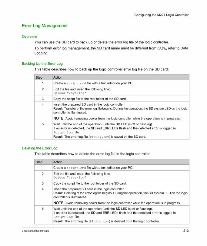
Configuring the M221 Logic Controller
Error Log Management
OverviewYou can use the SD card to back up or delete the error log file of the logic controller.To perform error log management, the SD card name must be different from DATA, refer to Data Logging.
Backing Up the Error LogThis table describes how to back up the logic controller error log file on the SD card:
Deleting the Error LogThis table describes how to delete the error log file in the logic controller:
Step Action1 Create a script.cmd file with a text editor on your PC.
2 Edit the file and insert the following line:Upload "/sys/log"
3 Copy the script file to the root folder of the SD card.4 Insert the prepared SD card in the logic controller.
Result: Transfer of the error log file begins. During the operation, the SD system LED on the logic controller is illuminated.
NOTE: Avoid removing power from the logic controller while the operation is in progress.
5 Wait until the end of the operation (until the SD LED is off or flashing).If an error is detected, the SD and ERR LEDs flash and the detected error is logged in Script.log file.Result: The error log file (PlcLog.csv) is saved on the SD card.
Step Action1 Create a script.cmd file with a text editor on your PC.
2 Edit the file and insert the following line:Delete "/sys/log"
3 Copy the script file to the root folder of the SD card.4 Insert the prepared SD card in the logic controller.
Result: Deleting of the error log file begins. During the operation, the SD system LED on the logic controller is illuminated.
NOTE: Avoid removing power from the logic controller while the operation is in progress.
5 Wait until the end of the operation (until the SD LED is off or flashing).If an error is detected, the SD and ERR LEDs flash and the detected error is logged in Script.log file.Result: The error log file (PlcLog.csv) is deleted from the logic controller.
EIO0000000976 02/2020 213

Configuring the M221 Logic Controller
Error Log FormatThe logic controller provides an error list containing the last 10 detected errors in the log memory. Each error entry into the error log file is composed of the following parts: Date and time Level Context Error code Priority (internal use only)After an upload through the SD card, the code is represented as in the example below: 02/06/14, 12:04:01, 0x0111000100This table describes the meaning of the hexadecimal error representation:
Group Error code (hex)
Error Description Result
General 08000011xx Invalid hardware calibration parameters Ethernet channel is inoperative%SW118.bit10 set to 0ERR LED flashes
Operating system 0F01xxxxxx Operating system error detected Transition to HALTED state
Memory management
0F030009xx Internal memory allocation error detected
Transition to HALTED state
SD card 010C001Bxx Error while accessing an SD card; the operation exceeded an internal timeout (3000 ms).
The SD card operation is canceled.
Watchdog timer 0104000Axx Logic controller resource utilization greater than 80% - first detection
Watchdog timeout signaled:%S11 set to 1ERR LED flashes
0804000Bxx Logic controller resource utilization greater than 80% - second consecutive detection
Transition to HALTED state
0804000Cxx Task watchdog timer in master task Transition to HALTED state0804000Dxx Task watchdog timer in periodic task Transition to HALTED state
Battery 0105000Exx Battery is depleted Depleted battery signaled:%S75 set to 1BAT LED illuminated
RTC 01060012xx RTC is invalid Invalid RTC signaled:%SW118.bit12 set to zero%S51 set to 1
214 EIO0000000976 02/2020

Configuring the M221 Logic Controller
User application 0807000Fxx Application is not compatible with firmware
Transition to EMPTY state
08070010xx Checksum error detected Transition to EMPTY state
Ethernet 010B0014xx Duplicate IP address detected Duplicate IP signaled:%SW62 set to 1%SW118.bit9 set to 0ERR LED flashes
Embedded I/O 010D0013xx Short-circuit detected on protected output
Over-current signaled:%SW139 set to 1 (depending on the output block)ERR LED flashes
Read non-volatile memory
01110000xx Read error detected - file not found Unsuccessful read operation 01110001xx Read error detected - incorrect logic
controller type01110002xx Read error detected - incorrect header01110003xx Read error detected - incorrect area
descriptor01110004xx Read error detected - incorrect area
descriptor size Write non-volatile memory
01120002xx Write error detected - incorrect header Unsuccessful write operation 01120004xx Write error detected - incorrect area
descriptor size01120005xx Write error detected - unsuccessful
erase01120006xx Write error detected - incorrect header
sizePersistent variable 01130007xx Checksum error detected in persistent
variablesPersistent variables cannot be restored
01130008xx Size error detected in persistent variables
Ethernet IP 01140012xx Unsuccessful Ethernet IP variable creation
Variable cannot be created, unsuccessful operation
Group Error code (hex)
Error Description Result
EIO0000000976 02/2020 215

Configuring the M221 Logic Controller
Memory Management: Backing Up and Restoring Controller Memory
OverviewYou can use an SD card to back up and restore controller memory objects, or copy the memory objects to another controller.
Backing Up Controller Memory
Restoring Controller Memory or Copying to Another Controller
Step Action1 Create a script.cmd file with a text editor on your PC.
2 Edit the file and insert the following line:Upload "/usr/mem"
3 Copy the script file to the root folder of the SD card.4 Insert the prepared SD card in the controller.
Result: Copying of the memory begins. During the operation, the SD system LED on the logic controller is illuminated.
NOTE: Avoid removing power from the logic controller while the operation is in progress.
NOTE: The memory backup process has a low priority to minimize impact on the program and communication performance of the logic controller. Depending on the amount of free time in your program, the operation may take considerably longer to complete if the logic controller is in RUNNING state compared to the STOPPED state.
5 Wait until the end of the operation (until the SD LED is off or flashing).If an error is detected, the SD and ERR LEDs flash and the detected error is logged in Script.log file.Result: The memory file (*.csv) is saved on the SD card.
Step Action1 Edit the script.cmd file in the root folder of the SD card with a text editor.
2 Replace the content of the script by the following line:Download "/usr/mem"
3 Insert the prepared SD card in the controller.Result: Copying of the memory file begins. During the operation, the SD system LED on the logic controller is illuminated.
NOTE: Avoid removing power from the logic controller while the operation is in progress.
4 Wait until the end of the operation (until the SD LED is off or flashing).If an error is detected, the SD and ERR LEDs flash and the detected error is logged in Script.log file.
216 EIO0000000976 02/2020

Modicon M221Programming the M221 Logic ControllerEIO0000000976 02/2020
Programming the M221 Logic Controller
Chapter 4Programming the M221 Logic Controller
OverviewThis part provides information about the system and I/O objects specific to the M221 Logic Controller. These objects are displayed in the Programming tab.For descriptions of all other objects, refer to EcoStruxure Machine Expert - Basic Generic Functions Library Guide.
What Is in This Chapter?This chapter contains the following sections:
Section Topic Page4.1 I/O Objects 2184.2 Network Objects 2244.3 System Objects 240
EIO0000000976 02/2020 217

Programming the M221 Logic Controller
I/O Objects
Section 4.1I/O Objects
What Is in This Section?This section contains the following topics:
Topic PageDigital Inputs (%I) 219Digital Outputs (%Q) 220Analog Inputs (%IW) 221Analog Outputs (%QW) 223
218 EIO0000000976 02/2020

Programming the M221 Logic Controller
Digital Inputs (%I)
IntroductionDigital input bit objects are the image of digital inputs on the logic controller.
Displaying Digital Input PropertiesFollow these steps to display properties of the digital inputs:
Digital Inputs PropertiesThis table describes each property of the digital input:
Step Action1 Select the Tools tab in the left-hand area of the Programming window.2 Click I/O objects → Digital inputs.
Result: Digital input properties appear on the screen.
Parameter Editable Value Default Value DescriptionUsed No True/False False Indicates whether the input channel is being
referenced in a program.Address No %I0.i – Displays the address of the digital input on
the controller, where i represents the channel number.If the controller has n digital input channels, the value of i is given as 0...n-1.For example, %I0.2 is the digital input at the digital input channel number 2 of the logic controller.
Symbol Yes – – The symbol associated with this address.Double-click in the Symbol column and type the name of the symbol to associate with this input. If a symbol already exists, you can right-click in the Symbol column and choose Search and Replace to find and replace occurrences of this symbol throughout the program and/or program comments.
Comment Yes – – A comment associated with this address.Double-click in the Comment column and type an optional comment to associate with this channel.
EIO0000000976 02/2020 219

Programming the M221 Logic Controller
Digital Outputs (%Q)
IntroductionDigital output bit objects are the image of digital outputs on the logic controller.
Displaying Digital Output PropertiesFollow these steps to display properties of the digital outputs:
Digital Outputs PropertiesThis table describes each property of the digital output:
Step Action1 Select the Tools tab in the left-hand area of the Programming window.2 Click I/O objects → Digital outputs.
Result: Digital output properties appear on the screen.
Parameter Editable Value Default Value DescriptionUsed No True/False False Indicates whether the output channel is
being referenced in a program.Address No %Q0.i – Displays the address of the digital output on
the controller, where i represents the channel number.If the controller has n digital output channels, the value of i is given as 0...n-1.For example, %Q0.3 is the digital output at the digital output channel number 3 of the logic controller.
Symbol Yes – – The symbol associated with this address.Double-click in the Symbol column and type the name of the symbol to associate with this output. If a symbol already exists, you can right-click in the Symbol column and choose Search and Replace to find and replace occurrences of this symbol throughout the program and/or program comments.
Comment Yes – – The comment associated with this address.Double-click in the Comment column and type an optional comment to associate with this channel.
220 EIO0000000976 02/2020

Programming the M221 Logic Controller
Analog Inputs (%IW)
IntroductionAnalog input word objects are the digital values of an analog signal connected to the logic controller.Two 0-10V analog inputs are embedded in the logic controller. The embedded analog inputs use a 10 bits resolution converter so that each increment is approximately 10 mV (10V/210-1). Once the system detects the value 1023, the channel is considered to be saturated.Refer to M221 Hardware Guide (see page 525) and TMC2 Cartridges Hardware Guide (see page 989) used in the configuration for more details.
Displaying Analog Input PropertiesFollow these steps to display properties of the analog inputs:
Analog Inputs PropertiesThis table describes each property of the analog input:
Step Action1 Select the Tools tab in the left-hand area of the Programming window.2 Click I/O objects → Analog inputs.
Result: Analog input properties appear on the screen.
Parameter Editable Value Default Value DescriptionUsed No True/False False Indicates whether the input channel is being
referenced in a program.Address No %IW0.i – Displays the address of the embedded
analog input on the controller, where i represents the channel number.If the controller has n analog input channels, the value of i is given as 0...n-1.For example, %IW0.1 is the analog input at the analog input channel number 1 of the logic controller.
%IW0.x0y – Displays the address of the analog output channel on the cartridge, where x is the cartridge number and and y is the channel number.
EIO0000000976 02/2020 221

Programming the M221 Logic Controller
Symbol Yes – – The symbol associated with this address.Double-click in the Symbol column and type the name of the symbol to associate with this input. If a symbol already exists, you can right-click in the Symbol column and choose Search and Replace to find and replace occurrences of this symbol throughout the program and/or program comments.
Comment Yes – – The comment associated with this address.Double-click in the Comment column and type a comment to associate with this address.
Parameter Editable Value Default Value Description
222 EIO0000000976 02/2020

Programming the M221 Logic Controller
Analog Outputs (%QW)
IntroductionAnalog output word objects are the digital values of the analog signals recieved from the logic controller using cartridges.Two 0-10 V analog outputs and two 4-20 mA analog outputs are embedded in the cartridges TMC2AQ2C and TMC2AQ2V respectively.Refer to TMC2 Cartridges Hardware Guide (see page 989) used in the configuration for more details.
Displaying Analog Output PropertiesFollow these steps to display properties of the analog outputs:
Analog Outputs PropertiesThis table describes each property of the analog output:
Step Action1 Select the Tools tab in the left-hand area of the Programming window.2 Click I/O objects → Analog outputs.
Result: Analog output properties appear on the screen.
Parameter Editable Value Default Value DescriptionUsed No True/False False Indicates whether the output channel is
being referenced in a program.Address No %QW0.x0y – Displays the address of the analog output
channel on the cartridge, where x is the cartridge number and and y is the channel number.
Symbol Yes – – The symbol associated with this address.Double-click in the Symbol column and type the name of the symbol to associate with this output. If a symbol already exists, you can right-click in the Symbol column and choose Search and Replace to find and replace occurrences of this symbol throughout the program and/or program comments.
Comment Yes – – The comment associated with this address.Double-click in the Comment column and type a comment to associate with this address.
EIO0000000976 02/2020 223

Programming the M221 Logic Controller
Network Objects
Section 4.2Network Objects
What Is in This Section?This section contains the following topics:
Topic PageInput Assembly (EtherNet/IP) Objects (%QWE) 225Output Assembly (EtherNet/IP) Objects (%IWE) 227Input Registers (Modbus TCP) Objects (%QWM) 228Output Registers (Modbus TCP) Objects (%IWM) 230Digital Input (IOScanner) Objects (%IN) 231Digital Output (IOScanner) Objects (%QN) 233Input Register (IOScanner) Objects (%IWN) 235Output Register (IOScanner) Objects (%QWN) 237Modbus IOScanner Network Diagnostic Codes (%IWNS) 239
224 EIO0000000976 02/2020

Programming the M221 Logic Controller
Input Assembly (EtherNet/IP) Objects (%QWE)
IntroductionInput assembly objects are the digital values of EtherNet/IP Input assembly frames received on the logic controller.
Displaying Input Assembly PropertiesFollow these steps to display properties of Input assembly objects:
Input Assembly PropertiesThis table describes each property of an Input assembly object:
Step Action1 Select the Tools tab in the left-hand area of the Programming window.2 Click Network objects → Input assembly (EtherNet/IP).
Result: The properties window appears.
Parameter Editable Value Default Value DescriptionUsed No TRUE/FALSE FALSE Indicates whether the object is being
referenced in a program.Address No %QWEi – The address of the Input assembly, where i
is the instance identifier.For the maximum number of instances, refer to Maximum Number of Objects (see page 52).
Symbol Yes – – The symbol associated with this address.Double-click in the Symbol column and type the name of the symbol to associate with this object. If a symbol already exists, you can right-click in the Symbol column and choose Search and Replace to find and replace occurrences of this symbol throughout the program and/or program comments.
EIO0000000976 02/2020 225

Programming the M221 Logic Controller
Fallback value Yes -32768...32767 0 Specify the value to apply to this object when the logic controller enters the STOPPED or an exception state.
NOTE: If Maintain values fallback mode is configured, the object retains its value when the logic controller enters the STOPPED or an exception state. The value 0 is displayed and cannot be edited. For more details, refer to Fallback Behavior (see EcoStruxure Machine Expert - Basic, Operating Guide).
Comment Yes – – A comment associated with this object.Double-click in the Comment column and type an optional comment to associate with this object.
Parameter Editable Value Default Value Description
226 EIO0000000976 02/2020

Programming the M221 Logic Controller
Output Assembly (EtherNet/IP) Objects (%IWE)
IntroductionOutput assembly objects are the digital values of EtherNet/IP Output assembly frames received on the logic controller.
Displaying Output Assembly PropertiesFollow these steps to display properties of Output assembly objects:
Output Assembly PropertiesThis table describes each property of an Output assembly object:
Step Action1 Select the Tools tab in the left-hand area of the Programming window.2 Click Network objects → Output assembly (EtherNet/IP).
Result: The properties window appears.
Parameter Editable Value Default value DescriptionUsed No TRUE/FALSE FALSE Indicates whether the object is being
referenced in a program.Address No %IWEi – The address of the Output assembly, where
i is the instance identifier.For the maximum number of instances, refer to Maximum Number of Objects (see page 52).
Symbol Yes – – The symbol associated with this address.Double-click in the Symbol column and type the name of the symbol to associate with this object. If a symbol already exists, you can right-click in the Symbol column and choose Search and Replace to find and replace occurrences of this symbol throughout the program and/or program comments.
Comment Yes – – A comment associated with this object.Double-click in the Comment column and type an optional comment to associate with this object.
EIO0000000976 02/2020 227

Programming the M221 Logic Controller
Input Registers (Modbus TCP) Objects (%QWM)
IntroductionInput registers objects are the digital values of Modbus TCP mapping table input registers received on the logic controller.
Displaying Input Registers PropertiesFollow these steps to display properties of Input registers objects:
Input Registers PropertiesThis table describes each property of an Input registers object:
Step Action1 Select the Tools tab in the left-hand area of the Programming window.2 Click Network objects → Input registers (Modbus TCP).
Result: The properties window appears.
Parameter Editable Value Default value DescriptionUsed No TRUE/FALSE FALSE Indicates whether the object is being
referenced in a program.Address No %QWMi – The address of the Input registers object,
where i is the instance identifier.For the maximum number of instances, refer to Maximum Number of Objects (see page 52).
Symbol Yes – – The symbol associated with this address.Double-click in the Symbol column and type the name of the symbol to associate with this object. If a symbol already exists, you can right-click in the Symbol column and choose Search and Replace to find and replace occurrences of this symbol throughout the program and/or program comments.
228 EIO0000000976 02/2020

Programming the M221 Logic Controller
Fallback value Yes -32768...32767 0 Specify the value to apply to this object when the logic controller enters the STOPPED or an exception state.
NOTE: If Maintain values fallback mode is configured, the object retains its value when the logic controller enters the STOPPED or an exception state. The value 0 is displayed and cannot be edited. For more details, refer to Fallback Behavior (see EcoStruxure Machine Expert - Basic, Operating Guide).
Comment Yes – – A comment associated with this object.Double-click in the Comment column and type an optional comment to associate with this object.
Parameter Editable Value Default value Description
EIO0000000976 02/2020 229

Programming the M221 Logic Controller
Output Registers (Modbus TCP) Objects (%IWM)
IntroductionOutput registers objects are the digital values of Modbus TCP mapping table output registers received on the logic controller.
Displaying Output Registers PropertiesFollow these steps to display properties of Output registers objects:
Output Registers PropertiesThis table describes each property of an Output registers object:
Step Action1 Select the Tools tab in the left-hand area of the Programming window.2 Click Network objects → Output registers (Modbus TCP).
Result: The properties window appears.
Parameter Editable Value Default value DescriptionUsed No TRUE/FALSE FALSE Indicates whether the object is being
referenced in a program.Address No %IWMi – The address of the Output registers object,
where i is the instance identifier.For the maximum number of instances, refer to Maximum Number of Objects (see page 52).
Symbol Yes – – The symbol associated with this address.Double-click in the Symbol column and type the name of the symbol to associate with this object. If a symbol already exists, you can right-click in the Symbol column and choose Search and Replace to find and replace occurrences of this symbol throughout the program and/or program comments.
Comment Yes – – A comment associated with this object.Double-click in the Comment column and type an optional comment to associate with this object.
230 EIO0000000976 02/2020

Programming the M221 Logic Controller
Digital Input (IOScanner) Objects (%IN)
IntroductionDigital input (IOScanner) objects are the digital values received from Modbus Serial IOScanner or Modbus TCP IOScanner devices.
Displaying Digital inputs (IOScanner) PropertiesFollow these steps to display properties of Digital inputs (IOScanner) objects:
Digital inputs (IOScanner) PropertiesThis table describes each property of an Digital inputs (IOScanner) object:
Step Action1 Select the Tools tab in the left-hand area of the Programming window.2 Click Network objects → Digital inputs (IOScanner).
Result: The properties window appears.
Parameter
Editable Value Default value Description
Used No TRUE/FALSE FALSE Indicates whether the object is being referenced in the program.
Address No %IN(i+x).y.z) – The address of the object, where: i: index: 100 for SL1 200 for SL2 300 for ETH1(Modbus TCP IOScanner)
x: device ID y: channel ID z: object instance identifier
For the maximum number of instances, refer to Maximum Number of Objects (see page 52).
Channel No Name of the configured channel.
- The name of the channel being used to receive the data from the device.
EIO0000000976 02/2020 231

Programming the M221 Logic Controller
Symbol Yes – – The symbol associated with this address.Double-click in the Symbol column and type the name of the symbol to associate with this object. If a symbol already exists, you can right-click in the Symbol column and choose Search and Replace to find and replace occurrences of this symbol throughout the program and/or program comments.
Comment Yes – – A comment associated with this object.Double-click in the Comment column and type an optional comment to associate with this object.
Parameter
Editable Value Default value Description
232 EIO0000000976 02/2020

Programming the M221 Logic Controller
Digital Output (IOScanner) Objects (%QN)
IntroductionDigital output (IOScanner) objects are the digital values sent to Modbus Serial IOScanner or Modbus TCP IOScanner devices.
Displaying Digital outputs (IOScanner) PropertiesFollow these steps to display properties of Digital outputs (IOScanner) objects:
Digital outputs (IOScanner) Object PropertiesThis table describes each property of a Digital outputs (IOScanner) object:
Step Action1 Select the Tools tab in the left-hand area of the Programming window.2 Click Network objects → Digital outputs (IOScanner).
Result: The properties window appears.
Parameter Editable Value Default value DescriptionUsed No TRUE/FALSE FALSE Indicates whether the object is being referenced
in a program.Address No %QN(i+x).y.z – The address of the object, where:
i: index: 100 for SL1 200 for SL2 300 for ETH1(Modbus TCP IOScanner)
x: device ID y: channel ID z: object instance identifier
For the maximum number of instances, refer to Maximum Number of Objects (see page 52).
Channel Yes Name of the configured channel.
- The name of the channel being used to send the data to the device.
Fallback value
Yes 0 or 1 0 Specify the value to apply to this object when the logic controller enters the STOPPED or an exception state.
NOTE: If Maintain values fallback mode is configured, the object retains its value when the logic controller enters the STOPPED or an exception state. The value 0 is displayed and cannot be edited. For more details, refer to Fallback Behavior.
EIO0000000976 02/2020 233

Programming the M221 Logic Controller
Symbol Yes – – The symbol associated with this address.Double-click in the Symbol column and type the name of the symbol to associate with this object. If a symbol already exists, you can right-click in the Symbol column and choose Search and Replace to find and replace occurrences of this symbol throughout the program and/or program comments.
Comment Yes – – A comment associated with this object.Double-click in the Comment column and type an optional comment to associate with this object.
Parameter Editable Value Default value Description
234 EIO0000000976 02/2020

Programming the M221 Logic Controller
Input Register (IOScanner) Objects (%IWN)
IntroductionInput register (IOScanner) objects are the register values received from Modbus Serial IOScanner or Modbus TCP IOScanner devices.
Displaying Input registers (IOScanner) PropertiesFollow these steps to display properties of Input registers (IOScanner) objects:
Input registers (IOScanner) PropertiesThis table describes each property of an Input registers (IOScanner) object:
Step Action1 Select the Tools tab in the left-hand area of the Programming window.2 Click Network objects → Input registers (IOScanner).
Result: The properties window appears.
Parameter Editable Value Default value DescriptionUsed No TRUE/FALSE FALSE Indicates whether the object is being referenced in
the program.Address No %IWN(i+x).y.z – The address of the object, where:
i: index: 100 for SL1 200 for SL2 300 for ETH1(Modbus TCP IOScanner)
x: device ID y: channel ID z: object instance identifier
For the maximum number of instances, refer to Maximum Number of Objects (see page 52).
Channel No Name of the configured channel.
- The name of the channel being used to receive the data from the device.
EIO0000000976 02/2020 235

Programming the M221 Logic Controller
Symbol Yes – – The symbol associated with this address.Double-click in the Symbol column and type the name of the symbol to associate with this object. If a symbol already exists, you can right-click in the Symbol column and choose Search and Replace to find and replace occurrences of this symbol throughout the program and/or program comments.
Comment Yes – – A comment associated with this object.Double-click in the Comment column and type an optional comment to associate with this object.
Parameter Editable Value Default value Description
236 EIO0000000976 02/2020
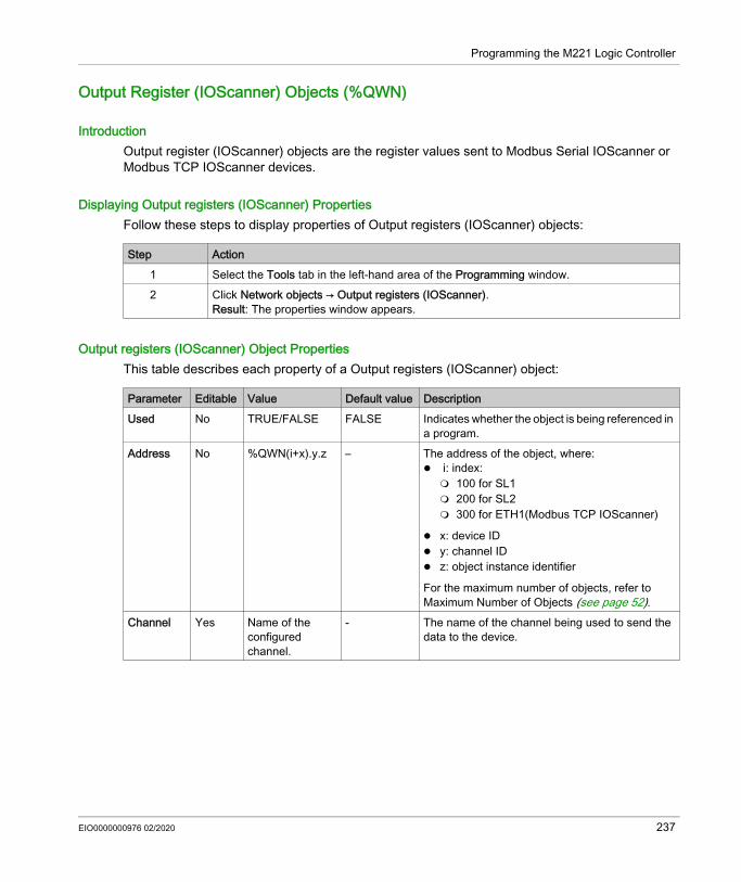
Programming the M221 Logic Controller
Output Register (IOScanner) Objects (%QWN)
IntroductionOutput register (IOScanner) objects are the register values sent to Modbus Serial IOScanner or Modbus TCP IOScanner devices.
Displaying Output registers (IOScanner) PropertiesFollow these steps to display properties of Output registers (IOScanner) objects:
Output registers (IOScanner) Object PropertiesThis table describes each property of a Output registers (IOScanner) object:
Step Action1 Select the Tools tab in the left-hand area of the Programming window.2 Click Network objects → Output registers (IOScanner).
Result: The properties window appears.
Parameter Editable Value Default value DescriptionUsed No TRUE/FALSE FALSE Indicates whether the object is being referenced in
a program.Address No %QWN(i+x).y.z – The address of the object, where:
i: index: 100 for SL1 200 for SL2 300 for ETH1(Modbus TCP IOScanner)
x: device ID y: channel ID z: object instance identifier
For the maximum number of objects, refer to Maximum Number of Objects (see page 52).
Channel Yes Name of the configured channel.
- The name of the channel being used to send the data to the device.
EIO0000000976 02/2020 237
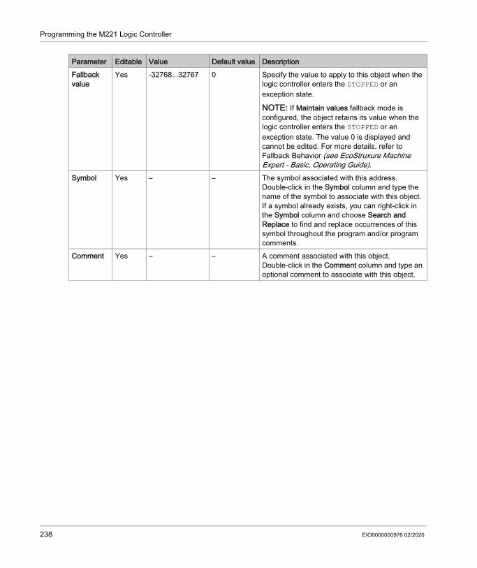
Programming the M221 Logic Controller
Fallback value
Yes -32768...32767 0 Specify the value to apply to this object when the logic controller enters the STOPPED or an exception state.
NOTE: If Maintain values fallback mode is configured, the object retains its value when the logic controller enters the STOPPED or an exception state. The value 0 is displayed and cannot be edited. For more details, refer to Fallback Behavior (see EcoStruxure Machine Expert - Basic, Operating Guide).
Symbol Yes – – The symbol associated with this address.Double-click in the Symbol column and type the name of the symbol to associate with this object. If a symbol already exists, you can right-click in the Symbol column and choose Search and Replace to find and replace occurrences of this symbol throughout the program and/or program comments.
Comment Yes – – A comment associated with this object.Double-click in the Comment column and type an optional comment to associate with this object.
Parameter Editable Value Default value Description
238 EIO0000000976 02/2020

Programming the M221 Logic Controller
Modbus IOScanner Network Diagnostic Codes (%IWNS)
Device Diagnostic CodesThe following table shows the possible values of the diagnostic codes returned by device x in the corresponding Modbus IOScanner network diagnostic object (%IWNS(100+x) for SL1, or %IWNS(200+x) for SL2, %IWNS(300+x) for ETH1):
Channel Diagnostic Codes The following table shows the possible values of the diagnostic codes returned by device x and channel y in the corresponding Modbus IOScanner network diagnostic object (%IWNS(100+x).y for SL1, %IWNS(200+x).y for SL2, %IWNS(300+x) for ETH1):
Value Description0 Device not scanned.1 Device is being initialized by Modbus IOScanner (Initialization request of device being sent).2 Device is present and ready to be scanned (initialization requests sent, if any). 3 Device not scanned correctly due to a communication error detected on a channel of the
device.4 Device not initialized correctly due to a communication error detected during initialization
request of the device.5 Device not correctly identified because the vendor name or product code returned by the
device does not match the expected values.6 Communication error occurred during identification and initialization. Possible reasons are:
incommunicative or absent device, incorrect communication parameters, or unsupported Modbus function.
Value Description0 Channel is active-1 Channel is inactiveOther Value of the Communication error code (CommError) (see EcoStruxure Machine Expert -
Basic, Generic Functions Library Guide)
EIO0000000976 02/2020 239

Programming the M221 Logic Controller
System Objects
Section 4.3System Objects
What Is in This Section?This section contains the following topics:
Topic PageSystem Bits (%S) 241System Words (%SW) 253Input Channel Status (%IWS) 278Output Channel Status (%QWS) 280
240 EIO0000000976 02/2020

Programming the M221 Logic Controller
System Bits (%S)
IntroductionThis section provides information about the function of system bits.
Displaying System Bits PropertiesFollow these steps to display properties of the system bits:
System Bits PropertiesThis table describes each property of the system bit:
Step Action1 Select the Tools tab in the left-hand area of the Programming window.2 Click System objects → System Bits.
Result: System bit properties appear on the screen.
Parameter Editable Value Default Value DescriptionUsed No TRUE/FALSE FALSE Indicates whether the system bit is being
referenced in a program.Address No %Si – Displays the system bit address, where i is
the bit number that represents the sequential position of the system bit in the memory.If the controller has maximum n system bits, the value of i is given as 0...n-1.For example, %S4 is system bit 4.
Symbol Yes – – The symbol associated with the system bit.Double-click in the Symbol column and type the name of the symbol to associate with the system bit. If a symbol already exists, you can right-click in the Symbol column and choose Search and Replace to find and replace occurrences of the symbol throughout the program and/or program comments.
Comment Yes – – A comment associated with the system bit.Double-click in the Comment column and type an optional comment to associate with the system bit.
EIO0000000976 02/2020 241

Programming the M221 Logic Controller
System Bits DescriptionThis table presents the description of the system bits and how they are controlled:
System Bit
Function Description Init State
Control
%S0 Cold Start Normally set to 0, it is set to 1 by: A power return with loss of data (battery malfunction), The program or an animation table.
This bit is set to 1 during the first complete scan. It is reset to 0 by the system before the next scan.
0 S or U→S, SIM
%S1 Warm Start Normally set to 0. It is set to 1 by a power return with data backup.It is reset to 0 by the system at the end of the complete scan.
0 S
%S4%S5%S6%S7
Time base: 10 msTime base: 100 msTime base: 1 sTime base: 1 min
The rate of status changes is measured by an internal clock. They are not synchronized with the controller scan. Example: %S4
– S, SIM (except %S4)
%S9 Fallback outputs When %S9 is set to 1: For outputs configured as Status Alarms, PTO, or
FREQGEN, the outputs are set to 0. Fallback values are applied to the physical digital and
analog outputs (embedded outputs, TM2/TM3 expansion module outputs and TMC2 cartridge outputs). The data image is unaffected by %S9. The data image reflects the logic applied by the application. Only the physical outputs are affected.
The fallback values are applied regardless of the fallback behavior (see EcoStruxure Machine Expert - Basic, Operating Guide) mode configured for specific outputs.
When %S9 is set to 0, the data image values are re-applied to the physical outputs.
NOTE: When the controller is in the STOPPED state and Maintain values fallback behavior is configured, a rising edge on %S9 applies fallback values to the physical outputs and to data image values.
0 U
S Controlled by the systemU Controlled by the userU→S Set to 1 by the user, reset to 0 by the systemS→U Set to 1 by the system, reset to 0 by the userSIM Applied in the Simulator
242 EIO0000000976 02/2020

Programming the M221 Logic Controller
%S10 I/O communication status
Normally set to 1 (TRUE on control panel). This bit can be set to 0 (FALSE on control panel) by the system when an I/O communication interruption is detected. When %S10=0, the ERR LED flashes.
1 S
%S11 Watchdog overflow Normally set to 0. This bit can be set to 1 by the system when the program execution time (scan time) exceeds the maximum scan time (application watchdog).Watchdog overflow causes the controller state to change to HALTED.%S11 is also set to 1 by the system if the processing load is greater than 80% of the processing capacity (refer to %SW75 (see page 253)). If the processor load is greater than 80% on any two consecutive measurements, the controller goes to HALTED state. Otherwise, %S11 is reset.
0 S
%S12 Logic controller in RUNNING state
This bit indicates that the controller is RUNNING.The system sets the bit to: 1 when the controller state is RUNNING, 0 for STOPPED, BOOTING, or any other state.
0 S, SIM
%S13 First cycle in RUNNING state
Normally set to 0. Set to 1 by the system during the first scan after the controller state has been changed to RUNNING.
0 S, SIM
%S14 I/O force activated Normally set to 0. Set to 1 by the system if at least one input or output is being forced.
0 S, SIM
%S15 Input forced Normally set to 0. Set to 1 by the system if at least one input is being forced.
0 S, SIM
%S16 Output forced Normally set to 0. Set to 1 by the system if at least one output is being forced.
0 S, SIM
%S17 Last ejected bit Normally set to 0. It is set by the system according to the value of the last ejected bit.It indicates the value of the last ejected bit.
0 S→U, SIM
System Bit
Function Description Init State
Control
S Controlled by the systemU Controlled by the userU→S Set to 1 by the user, reset to 0 by the systemS→U Set to 1 by the system, reset to 0 by the userSIM Applied in the Simulator
EIO0000000976 02/2020 243

Programming the M221 Logic Controller
%S18 Arithmetic overflow or error
Normally set to 0. It is set to 1 in the case of an overflow when a 16-bits operation is performed, that is: A result greater than + 32767 or less than - 32768, in
single length, A result greater than + 2147483647 or less than -
2147483648, in double length, A result greater than + 3.402824E+38 or less than -
3.402824E+38, in floating point, Division by 0, The square root of a negative number, BTI or ITB conversion not significant: BCD value out of
limits.It must be tested by the program after each operation where there is a risk of an overflow; then reset to 0 by the program if an overflow occurs.
0 S→U, SIM
%S19 Scan period overrun (periodic scan)
Normally set to 0, this bit is set to 1 by the system in the event of a scan period overrun (scan time greater than the period defined by the program at configuration or programmed in %SW0).This bit is reset to 0 by the program.
0 S→U
%S20 Index overflow Normally set to 0, it is set to 1 when the address of the indexed object becomes less than 0 or more than the maximum size of an object.It must be tested by the program after each operation where there is a risk of overflow; then reset to 0 if an overflow occurs.
0 S→U, SIM
%S21 Grafcet initialization Normally set to 0, it is set to 1 by: A cold restart, %S0 = 1, The program, in the preprocessing program part only,
using a Set Instruction (S %S21) or a set coil –(S)– %S21, The terminal.
At state 1, it causes Grafcet initialization. Active steps are deactivated and initial steps are activated.It is reset to 0 by the system after Grafcet initialization.
0 U→S, SIM
System Bit
Function Description Init State
Control
S Controlled by the systemU Controlled by the userU→S Set to 1 by the user, reset to 0 by the systemS→U Set to 1 by the system, reset to 0 by the userSIM Applied in the Simulator
244 EIO0000000976 02/2020

Programming the M221 Logic Controller
%S22 Grafcet reset Normally set to 0, it can only be set to 1 by the program in pre-processing.At state 1, it causes the active steps of the entire Grafcet to be deactivated. It is reset to 0 by the system at the start of the execution of the sequential processing.
0 U→S, SIM
%S23 Preset and freeze Grafcet (List)
Normally set to 0, it can only be set to 1 by the program in the pre-processing program module.Set to 1, it validates the pre-positioning of Grafcet (List). Maintaining this bit at 1 freezes Grafcet (List) execution. It is reset to 0 by the system at the start of the execution of the sequential processing.
0 U→S, SIM
%S28 String overflow Set to 1, it indicates that there is an overflow in a memory object when managing strings.
0 S→U, SIM
%S33 Read or Write selection for Ethernet server configuration read/change
Normally set to 0. Set to 0, the %SW33 to %SW38 contains the Ethernet
parameters in use (IP declared or IP assigned by BOOTP or automatic IP self assigned). These parameters are those configured in the application or those of the post configuration in SD card (in this case, %SW98 or %SW99 or %SW100 is different from 0).
Set to 1 (if there is no post configuration in use), then the new configuration is given by %SW33 to %SW38.
This bit can be set to its initial state 0 by the program and the system (on cold restart). Then, the Ethernet is reset to apply the application configuration whatever the current configuration is.This bit cannot be set to 1 if a post configuration is in use.
0 U→S
%S34 Ethernet Autonegotiation
Set to 0 to allow the autonegotiation of the speed and half or full duplex mode.Set to 1 to force some specific configuration set in %S35 and %S36.
NOTE: A modification in the state of %S34, %S35, or %S36 provokes a reinitialization of the Ethernet channel. As a consequence, the Ethernet channel may not be available for several seconds after the modification.
0 U
System Bit
Function Description Init State
Control
S Controlled by the systemU Controlled by the userU→S Set to 1 by the user, reset to 0 by the systemS→U Set to 1 by the system, reset to 0 by the userSIM Applied in the Simulator
EIO0000000976 02/2020 245

Programming the M221 Logic Controller
%S35 Ethernet half/full duplex mode
In case of the %S34 = 0 (autonegotiation) this bit will be set by the system, and it will be read only for the user. But is the %S34 = 1, the mode will be forced based on the value of this bit set by the user: Set to 0 if Half Duplex, Set to 1 if Full Duplex.
NOTE: A modification in the state of %S34, %S35, or %S36 provokes a reinitialization of the Ethernet channel. As a consequence, the Ethernet channel may not be available for several seconds after the modification.
– U or S
%S36 Ethernet speed In case of the %S34 = 0 (autonegotiation) this bit will be set by the system, and it will be read only for the user. But is the %S34 = 1, the mode will be forced based on the value of this bit set by the user: Set to 0 if 10 Mbps, Set to 1 if 100 Mbps.
NOTE: A modification in the state of %S34, %S35, or %S36 provokes a reinitialization of the Ethernet channel. As a consequence, the Ethernet channel may not be available for several seconds after the modification.
– U or S
%S38 Permission for events to be placed in the events queue
Normally set to 1. Set to 0, events cannot be placed in the events queue. Set to 1, events are placed in the events queue as soon
as they are detected,This bit can be set to its initial state 1 by the program and the system (on cold restart).
1 U→S
%S39 Saturation of the events queue
Normally set to 0. Set to 0, all events are reported. Set to 1, at least one event is lost.
This bit can be set to 0 by the program and the system (on cold restart).
0 U→S
System Bit
Function Description Init State
Control
S Controlled by the systemU Controlled by the userU→S Set to 1 by the user, reset to 0 by the systemS→U Set to 1 by the system, reset to 0 by the userSIM Applied in the Simulator
246 EIO0000000976 02/2020

Programming the M221 Logic Controller
%S49 Output rearming (see page 74)
Normally set to 0, this bit can be set to 1 or 0 by the program. Set to 0, the automatic re-arming of outputs following a
short circuit is disabled. Set to 1, the automatic re-arming of outputs following a
short circuit is enabled.
NOTE: The bit is reset to 0 on a cold start; otherwise, the bit value is retained.The system bit %S10 can be used to detect within your program that an output error has occurred. You can then use the system word %SW139 to determine programmatically in which cluster of outputs a short circuit or overload has occurred.
NOTE: %S10 and %SW139 are reset to their initial state when %S49 is set to 1.
0 U→S
System Bit
Function Description Init State
Control
S Controlled by the systemU Controlled by the userU→S Set to 1 by the user, reset to 0 by the systemS→U Set to 1 by the system, reset to 0 by the userSIM Applied in the Simulator
EIO0000000976 02/2020 247

Programming the M221 Logic Controller
%S50 Updating the date and time using words %SW49 to %SW53
Normally set to 0, this bit can be set to 1 or 0 by the program. Set to 0, the date and time can be read. Set to 1, the date and time can be updated but not read.
While %S50 is set to 1, the controller date and time are no longer updated by the system and cannot be read by the user program.The internal RTC controller is updated on a falling edge of %S50.Process details: If %S50=0, the controller regularly updates the system
words %SW49-53 from its internal clock. Reading %SW49-53 then provides the controller internal date & time.
Setting %S50 to 1 stops this update and allows to write to %SW49-53 without being overwritten by the above process.
When the controller detects a falling edge of %S50 (from 1 to 0), it applies the values of %SW49-53 to its internal clock and restarts the update of %SW49-53.
This %S50 process is also the mechanism used by EcoStruxure Machine Expert - Basic to update the controller time from the RTC management view. So if EcoStruxure Machine Expert - Basic detects that %S50 is already set to 1, a message informs that EcoStruxure Machine Expert - Basic cannot read the exact value of the controller internal clock. However, this situation does not prevent updates to the controller date & time from the RTC management view but, if used, %S50 will be reset by EcoStruxure Machine Expert - Basic.
0 U→S
System Bit
Function Description Init State
Control
S Controlled by the systemU Controlled by the userU→S Set to 1 by the user, reset to 0 by the systemS→U Set to 1 by the system, reset to 0 by the userSIM Applied in the Simulator
248 EIO0000000976 02/2020

Programming the M221 Logic Controller
%S51 Time-of-day clock status
Normally set to 0, this bit can be set to 1 or 0 by the program. Set to 0, the date and time are consistent. Set to 1, the date and time must be initialized by the
program.When this bit is set to 1, the time of day clock data is not valid. The date and time may never have been configured, the battery may be low, or the controller correction constant may be invalid (never configured, difference between the corrected clock value and the saved value, or value out of range). State 1 transitioning to state 0 forces a Write of the correction constant to the RTC.
0 U→S, SIM
%S52 RTC write error detected
This bit, managed by the system, is set to 1 to indicate that an RTC write (requested by %S50) has not been performed because of invalid values in %SW49 to %SW53 (see page 254). This bit is set to 0 if the requested RTC change has been correctly applied.
0 S, SIM
%S59 Updating the date and time using word %SW59
Normally set to 0, this bit can be set to 1 or 0 by the program. Set to 0, the system word %SW59 is not managed, Set to 1, the date and time are incremented or
decremented according to the rising edges on the control bits set in %SW59.
0 U
%S66 Battery LED If the battery is missing or in error, the battery LED is ON. Set this bit to 1 to deactivate the battery LED. This system bit is set to 0 at the start.
0 U→S
%S75 Battery status This system bit is set by the system and can be read by the user. It indicates the battery status: Set to 0, the external battery is operating normally. Set to 1, external battery power is low, or no external
battery is detected.
0 S
%S90 Backup/Restore/Erase destination
This system bit selects the destination of the memory words backup/restore/erase operation: Set to 0: non-volatile memory (default). Set to 1: SD card.
0 U
%S91 Erase backed up variables
Set this bit to 1 to erase the backed up variables stored in non-volatile memory or the SD card, depending on %90.
– U→S
System Bit
Function Description Init State
Control
S Controlled by the systemU Controlled by the userU→S Set to 1 by the user, reset to 0 by the systemS→U Set to 1 by the system, reset to 0 by the userSIM Applied in the Simulator
EIO0000000976 02/2020 249

Programming the M221 Logic Controller
%S92 %MW variables backed up in non-volatile memory
This system bit is set to 1 by the system if memory word (%MW) variables are available in non-volatile memory.
– S
%S93 Back up %MW Set this bit to 1 to back up the %MW variables in the non-volatile memory or SD card, depending on %S90.
– U→S
%S94 Restore %MW Set this bit to 1 to restore the data backed up in non-volatile memory or SD card, depending on %S90.
– U→S
%S96 Backup program OK This bit can be read at any time (either by the program or while adjusting), in particular after a cold start or a warm restart. Set to 0, the backup program is invalid. Set to 1, the backup program is valid.
0 S, SIM
%S101 Changing a port address (Modbus protocol)
Used to change a serial line port address using system words %SW101 (SL1) and %SW102 (SL2). To do this, %S101 must be set to 1. Set to 0, the address cannot be changed. The value of
%SW101 and %SW102 matches the current port address, Set to 1, the address can be changed by changing the
values of %SW101 (SL1) and %SW102 (SL2).
NOTE: %S101 cannot be set to 1 if a post configuration file is defined on SL1 or SL2.
0 U
System Bit
Function Description Init State
Control
S Controlled by the systemU Controlled by the userU→S Set to 1 by the user, reset to 0 by the systemS→U Set to 1 by the system, reset to 0 by the userSIM Applied in the Simulator
250 EIO0000000976 02/2020

Programming the M221 Logic Controller
%S103%S104
Using the ASCII protocol
Enables the use of the ASCII protocol on SL1 (%S103) or SL2 (%S104). The ASCII protocol is configured using system words %SW103 and %SW105 for SL1, and system words %SW104 and %SW106 for SL2. Set to 0, the protocol used is the one configured in
EcoStruxure Machine Expert - Basic, or specified in the post configuration (see page 79).
Set to 1, the ASCII protocol is used on SL1 (%S103) or SL2 (%S104). In this case, the system words %SW103, %SW105, and %SW121 must be previously configured for SL1, and %SW104, %SW106, and %SW122 for SL2. Each change of those %SW will be taken into account after a rising edge to %S103 or %S104.NOTE: A rising or falling edge on %S103 or %S104 cancels an exchange in progress (EXCH instruction).
NOTE: Setting %S103 or %S104 to 0 reconfigures the serial line with the EcoStruxure Machine Expert - Basic parameters.
NOTE: %S103 and %S104 are ignored if a Modbus Serial Line IOScanner is configured on the corresponding serial line.
0 U
%S105 Modem initialization command
Set to 1 to send the initialization command to the modem. Reset to 0 by the system. See also %SW167 (see page 253).
0 U/S
%S106 I/O bus behavior The default value is 0, meaning that a bus communication error on an expansion module (see page 127) stops the I/O expansion bus exchanges. Set this bit to 1 to specify that the controller continues to make I/O expansion bus exchanges.
NOTE: When a bus communication error occurs, bit n of %SW120 is set to 1, where n is the expansion module number, and %SW118 bit 14 is set to 0.For more information on bus error handling, refer to I/O Configuration General Description (see page 127).
0 U/S
System Bit
Function Description Init State
Control
S Controlled by the systemU Controlled by the userU→S Set to 1 by the user, reset to 0 by the systemS→U Set to 1 by the system, reset to 0 by the userSIM Applied in the Simulator
EIO0000000976 02/2020 251

Programming the M221 Logic Controller
%S107 I/O bus restart The default value is 0. Reset to 0 by the system.Set this bit to 1 to force a restart of the I/O expansion bus (see page 129). On detection of a rising edge of this bit, the logic controller reconfigures and restarts the I/O expansion bus if: %S106 is set to 0 (that is, I/O exchanges are stopped) %SW118 bit 14 is set to 0 (I/O bus is in error) At least one bit of %SW120 is set to 1 (identifying the
module that is in bus communication error)For more information on bus error handling, refer to I/O Configuration General Description (see page 127).
0 U/S
%S110 IOScanner reset SL1 Set to 1 to reset the Modbus Serial IOScanner on Serial Line 1.
0 U/S
%S111 IOScanner reset SL2 Set to 1 to reset the Modbus Serial IOScanner on Serial Line 2.
0 U/S
%S112 IOScanner reset ETH1
Set to 1 to reset the Modbus TCP IOScanner on Ethernet. 0 U/S
%S113 IOScanner suspend SL1
Set to 1 to suspend the Modbus Serial IOScanner on Serial Line 1.
0 U/S
%S114 IOScanner suspend SL2
Set to 1 to suspend the Modbus Serial IOScanner on Serial Line 2.
0 U/S
%S115 IOScanner suspend ETH1
Set to 1 to suspend the Modbus TCP IOScanner on Ethernet.
0 U/S
%S119 Local I/O error detected
Normally set to 1. This bit can be set to 0 when an I/O communication interruption is detected on the logic controller. %SW118 determines the nature of the communication interruption. Resets to 1 when the communication interruption disappears.
1 S
%S122 Automatically switch to Alarm page
Set to 1, the Remote Graphic Display automatically switches to the Alarm page when a rising edge is detected on an alarm bit.
0 U
%S123 Display red backlight on alarm
Set to 1, the backlight on the Remote Graphic Display is red when an alarm is active.
0 U
System Bit
Function Description Init State
Control
S Controlled by the systemU Controlled by the userU→S Set to 1 by the user, reset to 0 by the systemS→U Set to 1 by the system, reset to 0 by the userSIM Applied in the Simulator
252 EIO0000000976 02/2020

Programming the M221 Logic Controller
System Words (%SW)
IntroductionThis section provides information about the function of system words.
Displaying System Words PropertiesFollow these steps to display properties of the system words:
System Words PropertiesThis table describes each property of the system word:
Step Action1 Select the Tools tab in the left-hand area of the Programming window.2 Click System objects → System Words.
Result: System word properties appear on the screen.
Parameter Editable Value Default Value DescriptionUsed No TRUE/FALSE FALSE Indicates whether the system word is being
referenced in a program.Address No %SWi – Displays the system word address, where i
is the word number that represents the sequential position of the system word in the memory.If the controller has maximum n system words, the value of i is given as 0...n-1.For example, %SW50 is system word 50.
Symbol Yes – – The symbol associated with the system word.Double-click in the Symbol column and type the name of the symbol to associate with the system word.If a symbol already exists, you can right-click in the Symbol column and choose Search and Replace to find and replace occurrences of the symbol throughout the program and/or program comments.
Comment Yes – – A comment associated with the system word.Double-click in the Comment column and type an optional comment to associate with the system word.
EIO0000000976 02/2020 253

Programming the M221 Logic Controller
System Words DescriptionThis table presents the description of the system words and how they are controlled:
System Words
Function Description Control
%SW0 Controller scan period (master task set to periodic scan mode)
Modifies the controller scan period (1...150 ms) defined in the Master task properties (see EcoStruxure Machine Expert - Basic, Operating Guide) or an animation table.
U, SIM
%SW1 Periodic task period
Modifies the cycle time [1...255 ms] of the periodic task, without losing the Period value specified in the periodic task properties window. Allows you to recover the Period value saved in the periodic task properties window: in case of a cold start, or if the value you write in %SW1 is outside [1...255] range.
The %SW1 value can be modified in the program at each end of a cycle, in the program or in an animation table without having to stop the program. Cycle times can be correctly observed while the program is running.
U, SIM
%SW6 Controller state%MW60012
Controller state:0 = EMPTY2 = STOPPED3 = RUNNING4 = HALTED5 = POWERLESS
S, SIM
S Controlled by the systemU Controlled by the userSIM Applied in the simulator
254 EIO0000000976 02/2020

Programming the M221 Logic Controller
%SW7 Controller status
Bit [0]: Backup/restore in progress: Set to 1 if backup/restore of the program is in progress, Set to 0 if backup/restore of the program is complete or disabled.
Bit [1]: Configuration of the controller is OK: Set to 1 if configuration ok.
Bit [2]: SD card status bits: Set to 1 if SD card is present.
Bit [3]: SD card status bits: Set to 1 if SD card is being accessed.
Bit [4]: Application memory status: Set to 1 if application in RAM memory is different from that in non-
volatile memory. Bit [5]: SD card status bits: Set to 1 if SD card is in error.
Bit [6]: Not used (status 0) Bit [7]: Controller reserved: Set to 1 when the controller is connected to EcoStruxure Machine
Expert - Basic. Bit [8]: Application in Write mode: Set to 1 if application is protected. In this case, the clone operation
does not replicate the application (refer to Clone Management (see page 203)).
Bit [9]: Not used (status 0) Bit [10]: Second serial port installed as cartridge (compact only): 0 = No serial cartridge 1 = Serial cartridge installed
Bit [11]: Second serial port type: Set to 1 = EIA RS-485
Bit [12]: Validity of the application in internal memory: Set to 1 if the application is valid.
Bit [14]: Validity of the application in RAM memory: Set to 1 if the application is valid.
Bit [15]: Ready for execution: Set to 1 if ready for execution.
S, SIM
%SW11 Software watchdog value
Contains the maximum value of the watchdog. The value (10...500 ms) is defined by the configuration.
U, SIM
System Words
Function Description Control
S Controlled by the systemU Controlled by the userSIM Applied in the simulator
EIO0000000976 02/2020 255

Programming the M221 Logic Controller
%SW13 Boot loader versionxx.yy
For example, if %SW13=000E hex: 8 MSB=00 in hexadecimal, then xx=0 in decimal 8 LSB=0E in hexadecimal, then yy=14 in decimal
As a result, boot loader version is 0.14, displayed as 14 decimal.
S, SIM
%SW14 Commercial version, xx.yy
For example, if %SW14=0232 hex: 8 MSB=02 in hexadecimal, then xx=2 in decimal 8 LSB=32 in hexadecimal, then yy=50 in decimal
As a result, commercial version is 2.50, displayed as 250 decimal.
S, SIM
%SW15-%SW16
Firmware version aa.bb.cc.dd
For example, if:%SW15=0003 hex: 8 MSB=00 in hexadecimal, then aa=00 in decimal 8 LSB=03 in hexadecimal, then bb=03 in decimal
%SW16=0B16 hex: 8 MSB=0B in hexadecimal, then cc=11 in decimal 8 LSB=16 in hexadecimal, then dd=22 in decimal
As a result, firmware version is 0.3.11.22 displayed as 00031122 decimal.
S, SIM
%SW17 Default status for floating operation
When an error is detected in a floating arithmetic operation, bit %S18 is set to 1 and the default status of %SW17 is updated according to the following coding: Bit[0]: Invalid operation, result is not a number (NaN) Bit[1]: Reserved Bit[2]: Division by 0, result is invalid (-Infinity or +Infinity) Bit[3]: Result greater in absolute value than +3.402824e+38, result is
invalid (-Infinity or +Infinity).It must be tested by the program after each operation where there is a possible overflow; then reset to 0 by the program if an overflow occurs.
S and U, SIM
%SW18-%SW19
100 ms absolute timer counter
This counter works using 2 words: %SW18 represents the least significant word, %SW19 represents the most significant word.
The double word (%SW18-%SW19) increases from 0 to 2^31 each 100 ms as a counter modulo 2^31.This double word is also reset during the initialization phase and on a reset of %S0.
S and U, SIM
%SW30 Last scan time (master task)
Indicates the execution time of the last controller scan cycle (in ms).
NOTE: This time corresponds to the time elapsed between the start (acquisition of inputs) and the end (update of outputs) of a master task scan cycle. If the scan time is 2.250 ms, the %SW30 is 2 and the %SW70 is 250.
S
System Words
Function Description Control
S Controlled by the systemU Controlled by the userSIM Applied in the simulator
256 EIO0000000976 02/2020

Programming the M221 Logic Controller
%SW31 Max. scan time (master task)
Indicates the execution time of the longest controller scan cycle since the last cold start (in ms).This time corresponds to the time elapsed between the start (acquisition of inputs) and the end (update of outputs) of a scan cycle. If the maximum scan time is 2.250 ms, the %SW31 will be 2 and the %SW71 will be 250.
NOTE: To detect a pulse signal when the latching input option is selected, the pulse width (TON) and the period (P) must meet the following 2 requirements: TON ≥ 1 ms The input signal period (P) follows the Nyquist-Shannon sampling rule
stating that the input signal period (P) is at least twice the maximum program scan time (%SW31): P ≥ 2 x %SW31.
S
%SW32 Min. scan time (master task)
Indicates the execution time of shortest controller scan cycle since the last cold start (in ms).
NOTE: This time corresponds to the time elapsed between the start (acquisition of inputs) and the end (update of outputs) of a scan cycle. If the minimum scan time is 2.250 ms, the %SW32 is 2 and the %SW72 is 250.
S
%SW33%SW34%SW35%SW36%SW37%SW38
IP address for Ethernet server configuration read/write
The IP settings can be modified. The read or write selection is done using the system bit %S33.The system words %SW33...%SW38 contains the Ethernet parameters: IP address: %SW33 and %SW34
For IP address AA.BB.CC.DD: %SW33 = CC.DD and %SW34 = AA.BB Subnetwork mask: %SW35 and %SW36
For subnetwork mask AA.BB.CC.DD: %SW35 = CC.DD and %SW36 = AA.BB
Gateway address: %SW37 and %SW38For gateway address AA.BB.CC.DD: %SW37 = CC.DD and %SW38 = AA.BB
U
%SW39 Periodic average time
Indicates the average execution time in µs of the periodic task (last 5 times). –
%SW40 Event 0 average time
Indicates the average execution time in µs of the event task associated with the input %I0.2 (last 5 times).
–
%SW41 Event 1 average time
Indicates the average execution time in µs of the event task associated with the input %I0.3 (last 5 times).
–
%SW42 Event 2 average time
Indicates the average execution time in µs of the event task associated with the input %I0.4 (last 5 times).
–
System Words
Function Description Control
S Controlled by the systemU Controlled by the userSIM Applied in the simulator
EIO0000000976 02/2020 257

Programming the M221 Logic Controller
%SW43 Event 3 average time
Indicates the average execution time in µs of the event task associated with the input %I0.5 (last 5 times).
–
%SW44 Event 4 average time
Indicates the average execution time in µs of the event task associated with the Threshold 0 of HSC0 or HSC2 (last 5 times).
–
%SW45 Event 5 average time
Indicates the average execution time in µs of the event task associated with the Threshold 1 of HSC0 or HSC2 (last 5 times).
–
%SW46 Event 6 average time
Indicates the average execution time in µs of the event task associated with the Threshold 0 of HSC1 or HSC3 (last 5 times).
–
%SW47 Event 7 average time
Indicates the average execution time in µs of the event task associated with the Threshold 1 of HSC1 or HSC3 (last 5 times).
–
%SW48 Number of events
Indicates how many events have been executed since the last cold start. (Counts all events except cyclic events.)
NOTE: Set to 0 (after application loading and cold start), increments on each event execution.
S, SIM
%SW49%SW50%SW51%SW52%SW53
Real-Time Clock (RTC)
RTC functions: words containing current date and time values (in BCD): S and U, SIM%SW49 xN Day of the week (N=1 for
Monday)
NOTE: %SW49 is read only (S).%SW50 00SS Seconds%SW51 HHMM: hour and minute%SW52 MMDD: month and day%SW53 CCYY: century and yearSet system bit %S50 to 1 to enable updating the RTC value using system words %SW49 to %SW53. On a falling edge of %S50 the internal RTC controller is updated using the values written in these words. For more details, see system bit %S50 (see page 242).
%SW54%SW55%SW56%SW57
Date and time of the last stop
System words containing the date and time of the last power outage or controller stop (in BCD):
S, SIM
%SW54 SS Seconds%SW55 HHMM: hour and minute%SW56 MMDD: month and day%SW57 CCYY: century and year
System Words
Function Description Control
S Controlled by the systemU Controlled by the userSIM Applied in the simulator
258 EIO0000000976 02/2020

Programming the M221 Logic Controller
%SW58 Code of last stop
Displays code giving cause of last transition from the RUNNING state to another state:
S, SIM
0 Initial value (after a download or an initialization command)
1 Run/Stop input or Run/Stop switch is set to 0. A falling edge on the Run/Stop input or Run/Stop switch at 0 has been detected while the controller was in the RUNNING state, or the controller was powered on with the Run/Stop input or Run/Stop switch at 0.
2 Program error detected. A program error has been detected while the controller was in the RUNNING state (in which case the controller goes to the HALTED state), or the controller was in the HALTED state when the power was cycled, preventing it starting in run.
3 Stop command using EcoStruxure Machine Expert - Basic online button or Remote Graphic Display.
4 Power outage. The controller starting in run after a power cycle, or the controller is in the STOPPED state because the starting mode is Start in Previous State and the controller was in the STOPPED state when the power outage occurred.
5 Hardware error detected.6 Not used.7 Power on with starting mode configured as Start in stop.8 The controller could not recover previous data that it had
at last power outage (for example because the battery is low), preventing it starting in run.
9 Controller is not able to run due to internal memory errors.
The reasons for the last stop are prioritized in the following order (that is, when the controller is in the STOPPED state after a power cycle): 1, 7, 4, 8, 2
System Words
Function Description Control
S Controlled by the systemU Controlled by the userSIM Applied in the simulator
EIO0000000976 02/2020 259

Programming the M221 Logic Controller
%SW59 Adjust current date
Adjusts the current date.Contains 2 sets of 8 bits to adjust current date.The operation is always performed on rising edge of the bit. This word is enabled by bit %S59.
U
Increment Decrement Parameterbit 0 bit 8 Day of weekbit 1 bit 9 Secondsbit 2 bit 10 Minutesbit 3 bit 11 Hoursbit 4 bit 12 Daysbit 5 bit 13 Monthbit 6 bit 14 Yearsbit 7 bit 15 Centuries
%SW62 Ethernet error detection
Indicates the error code:0 - No error detected1 - Duplicate IP: the M221 Logic Controller is configured with its default IP address (generated from the MAC address)2 - DHCP in progress3 - BOOTP in progress4 - Invalid parameters: port is disabled5 - Fixed IP address initialization in progress6 - Ethernet link down
S
System Words
Function Description Control
S Controlled by the systemU Controlled by the userSIM Applied in the simulator
260 EIO0000000976 02/2020

Programming the M221 Logic Controller
%SW63 EXCH1 block error code
EXCH1 error code:0 - operation was successful1 - number of bytes to be transmitted exceeds the limit (> 255)2 - insufficient transmission table3 - insufficient word table4 - receive table overflowed5 - time-out elapsed6 - transmission7 - incorrect command within table8 - selected port not configured/available9 - reception error: This error code reflects an incorrect or corrupted reception frame. It can be caused due to an incorrect configuration in the physical parameters (for example, parity, data bits, baudrate, and so on) or an unreliable physical connection causing signal degradation.10 - cannot use %KW if receiving11 - transmission offset larger than transmission table12 - reception offset larger than reception table13 - controller stopped EXCH processing
S
%SW64 EXCH2 block error code
EXCH2 error code: See %SW63. S
%SW65 EXCH3 block error code
1-4, 6-13: See %SW63. (Note that error code 5 is invalid and replaced by the Ethernet-specific error codes 109 and 122 described below.)The following are Ethernet-specific error codes:101 - incorrect IP address102 - no TCP connection103 - no socket available (all connection channels are busy)104 - network is down105 - network cannot be reached106 - network dropped connection on reset107 - connection aborted by peer device108 - connection reset by peer device109 - connection time-out elapsed110 - rejection on connection attempt111 - host is down120 - incorrect index (remote device is not indexed in configuration table)121 - system error (MAC, chip)122 - receiving process timed-out after data was sent123 - Ethernet initialization in progress
S
%SW67 Function and type of controller
Contains the logic controller code ID. For more information, refer to the M221 Logic Controller Code ID table (see page 276).
S, SIM
System Words
Function Description Control
S Controlled by the systemU Controlled by the userSIM Applied in the simulator
EIO0000000976 02/2020 261

Programming the M221 Logic Controller
%SW70 Scan timemicroseconds resolution
Indicates the execution time of the last controller scan cycle (in µs).
NOTE: This time corresponds to the time elapsed between the start (acquisition of inputs) and the end (update of outputs) of a master task scan cycle. If the scan time is 2.250 ms, the %SW30 will be 2 and the %SW70 will be 250.
–
%SW71 Max. scan timemicroseconds resolution
Indicates the execution time of the longest controller scan cycle since the last cold start (in ms).
NOTE: This time corresponds to the time elapsed between the start (acquisition of inputs) and the end (update of outputs) of a scan cycle. If the scan time is 2.250 ms, the %SW31 will be 2 and the %SW71 will be 250.
–
%SW72 Min. scan timemicroseconds resolution
Indicates the execution time of the shortest controller scan cycle since the last cold start (in ms).
NOTE: This time corresponds to the time elapsed between the start (acquisition of inputs) and the end (update of outputs) of a scan cycle. If the scan time is 2.250 ms, the %SW32 will be 2 and the %SW72 will be 250.
–
%SW75 Load of processor
Indicates the percentage of processing load.Processing load is defined as the percentage of the total available processing time that is used to process your program tasks (this value is an average and it is calculated every second). In case of processing load higher than 80% for two consecutive periods of time, the controller goes to HALTED state.
S
%SW76 to %SW79
Down counters 1-4
These 4 words serve as 1 ms timers. They are decremented individually by the system every ms if they have a positive value. This gives 4 down counters down counting in ms which is equal to an operating range of 1 ms to 32767 ms. Setting bit 15 to 1 can stop decrementation.
S and U, SIM
%SW80 Status of embedded analog inputs
Bit [0]: Set to 1 if the embedded analog inputs are operational Bit [6]: Set to 1 if an error is detected on analog input 0 Bit [7]: Set to 1 if an error is detected on analog input 1 All other bits are reserved and set to 1
S and U, SIM
%SW94%SW95
Application signature%MW60028-%MW60034
If the application changes, in terms of configuration or programming data, the signature (sum of all checksums) also changes.If %SW94 = 91F3 in hexadecimal, the application signature is 91F3 in hexadecimal.
S, SIM
System Words
Function Description Control
S Controlled by the systemU Controlled by the userSIM Applied in the simulator
262 EIO0000000976 02/2020

Programming the M221 Logic Controller
%SW96 Diagnostics for save/restore function of program and %MW
Bit [1]: This bit is set by the firmware to indicate when the save is complete: Set to 1 if the backup is complete. Set to 0 if a new backup is requested.
Bit [2]: Back up error detected, refer to bits 8, 9, 10, 12 and 14 for further information: Set to 1 if an error is detected. Set to 0 if a new backup is requested.
Bit [6]: Set to 1 if the controller contains a valid application in RAM memory.
Bit [10]: Difference detected between RAM memory and non-volatile memory. Set to 1 if there is a difference.
Bit [12]: Indicates if a restore error has occurred: Set to 1 if an error is detected.
Bit [14]: Indicates if a non-volatile memory write error has occurred: Set to 1 if an error is detected.
S, SIM
%SW98 Post configuration status (Serial Line 1)
The bits are set to 1 when the post configuration was applied for the parameter: Bit[0]: Hardware option (RS485 or RS232) Bit[1]: Baudrate Bit[2]: Parity Bit[3]: Data size Bit[4]: Number of stop bits Bit[5]: Modbus address Bit[6]: Polarization (if available in the port)
S
%SW99 Post configuration status (Serial Line 2)
The bits are set to 1 when the post configuration was applied for the parameter: Bit[0]: Hardware option (RS485) Bit[1]: Baudrate Bit[2]: Parity Bit[3]: Data size Bit[4]: Number of stop bits Bit[5]: Modbus address Bit[6]: Polarization (if available in the port)
S
System Words
Function Description Control
S Controlled by the systemU Controlled by the userSIM Applied in the simulator
EIO0000000976 02/2020 263

Programming the M221 Logic Controller
%SW100 Post configuration status (Ethernet)
The bits are set to 1 when the post configuration was applied for the parameter: Bit[0]: IP mode (fixed, DHCP, or BOOTP) Bit[1]: IP address Bit[2]: Network submask Bit[3]: Default gateway Bit[4]: Device name
NOTE: The post configuration has priority over the configuration provided by your application. The configuration of your application is not taken into account if the M221 Logic Controller has a post configuration.
S
%SW101%SW102
Value of the Modbus address port
When bit %S101 is set to 1, you can change the Modbus address of SL1 or SL2. The address of SL1 is %SW101. The address of SL2 is %SW102.
NOTE: The update is applied immediately after writing a new address to %SW101 or %SW102.
U
System Words
Function Description Control
S Controlled by the systemU Controlled by the userSIM Applied in the simulator
264 EIO0000000976 02/2020
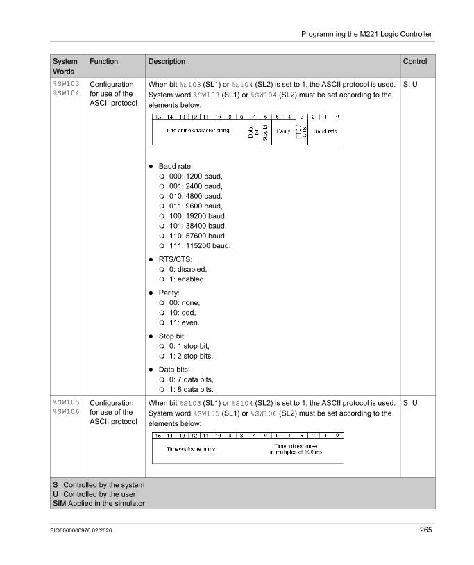
Programming the M221 Logic Controller
%SW103%SW104
Configuration for use of the ASCII protocol
When bit %S103 (SL1) or %S104 (SL2) is set to 1, the ASCII protocol is used. System word %SW103 (SL1) or %SW104 (SL2) must be set according to the elements below:
Baud rate: 000: 1200 baud, 001: 2400 baud, 010: 4800 baud, 011: 9600 baud, 100: 19200 baud, 101: 38400 baud, 110: 57600 baud, 111: 115200 baud.
RTS/CTS: 0: disabled, 1: enabled.
Parity: 00: none, 10: odd, 11: even.
Stop bit: 0: 1 stop bit, 1: 2 stop bits.
Data bits: 0: 7 data bits, 1: 8 data bits.
S, U
%SW105%SW106
Configuration for use of the ASCII protocol
When bit %S103 (SL1) or %S104 (SL2) is set to 1, the ASCII protocol is used. System word %SW105 (SL1) or %SW106 (SL2) must be set according to the elements below:
S, U
System Words
Function Description Control
S Controlled by the systemU Controlled by the userSIM Applied in the simulator
EIO0000000976 02/2020 265

Programming the M221 Logic Controller
%SW107%SW108%SW109
MAC address Indicates the controller MAC address (only references with Ethernet channel).For MAC address AA:BB:CC:DD:EE:FF: %SW107 = AA:BB %SW108 = CC:DD %SW109 = EE:FF
S
%SW114 Enable schedule blocks
Enables or disables operation of schedule blocks by the program: Bit [0]: Enable/disable schedule block number 0 Set to 0: disabled Set to 1: enabled
... Bit [15]: Enable/disable schedule block number 15 Set to 0: disabled Set to 1: enabled
Initially all schedule blocks are enabled.The default value is FFFF hex.
S and U, SIM
%SW115%SW116%SW117
Controller serial numbers part 1, 2, and 3 respectively (in BCD)
Allows to obtain the serial number of the controller.Example with the serial number 8A160400008: %SW115 : 16#0008 %SW116 : 16#6040 %SW117 : 16#0001
S
System Words
Function Description Control
S Controlled by the systemU Controlled by the userSIM Applied in the simulator
266 EIO0000000976 02/2020

Programming the M221 Logic Controller
%SW118 Logic controller status word
Indicates conditions on logic controller.For a controller operating normally, the value of this word is FFFF hex. Bit [9]: Set to 0: External error detected or communication interruption, for
example duplicate IP address Set to 1: No error detected.
Bit [10]: Set to 0: Invalid internal configuration; contact Schneider Electric
customer service. Set to 1: No error detected.
Bit [13]: Set to 0: Configuration error detected (mandatory modules, as defined
by the I/O expansion bus configuration, are absent or otherwise inoperative when the logic controller attempts to start the I/O expansion bus). In this case, the I/O bus does not start.
Set to 1: No error detected.
Bit [14]: Set to 0: One or more modules have ceased communication with the
logic controller after the I/O expansion bus is started. This is the case whether an I/O expansion module is defined as mandatory or optional but present at start-up.
Set to 1: No error detected.
For more information on bus error handling, refer to I/O Configuration General Description (see page 127).
Bit [15]: Set to 0: Cartridge error detected (configuration or runtime operation). Set to 1: No error detected.
NOTE: The other bits of this word are set to 1 and are reserved.
S, SIM
%SW119 Optional module feature configuration
One bit for each expansion module in the configuration: Bit [0]: Reserved for the logic controller Bit n: Module n Set to 1: Module is marked as optional in the configuration. Set to 0: Module is not marked as optional in the configuration.
S, SIM
System Words
Function Description Control
S Controlled by the systemU Controlled by the userSIM Applied in the simulator
EIO0000000976 02/2020 267

Programming the M221 Logic Controller
%SW120 Expansion I/O module status
1 bit for each expansion module in the configuration.Bit 0: Reserved for the logic controllerWhen the logic controller attempts to start the I/O bus, bit n: 0 = no error detected 1 = error detected or module not present. The I/O expansion bus does not
start unless the corresponding bit in %SW119 is set to TRUE (indicating the module is marked as optional).
After the bus started and is running with data exchanges with the controller, bit n: 0 = no error detected 1 = error detected on the I/O expansion module (regardless if it is a module
marked as optional).For more information on bus error handling, refer to I/O Configuration General Description (see page 127).
S, SIM
%SW121%SW122
Configuration for use of ASCII protocol
When bit %S103 (SL1) or %S104 (SL2) is set to 1, the ASCII protocol is used. You can change the ASCII frame size of SL1 or SL2. The ASCII frame size of SL1 is %SW121, and that of SL2 is %SW122.
U
System Words
Function Description Control
S Controlled by the systemU Controlled by the userSIM Applied in the simulator
268 EIO0000000976 02/2020

Programming the M221 Logic Controller
%SW128 Cartridge 1 status
Indicates the status code for the cartridge: LSB: presents the status of the I/O channel 1 MSB: presents the status of the I/O channel 2
General status: 0x80: Cartridge is not present and it is not configured in EcoStruxure
Machine Expert - Basic. 0x81: Module is present, but it is not configured. 0x82: Internal communication error with the cartridge. 0x83: Internal communication error with the cartridge. 0x84: Detected cartridge different from the configuration. 0x85: Configured cartridge is not detected.
Input channel operation status: 0x00: Normal. 0x01: Conversion in progress. 0x02: Initialization. 0x03: Input operation setting error detected or module without input. 0x04: Reserved. 0x05: Wiring error detected (High limit range out). 0x06: Wiring error detected (Low limit range out). 0x07: Non-volatile memory error detected. Others: Reserved.
Output channel operation status: 0x00: Normal. 0x01: Reserved. 0x02: Initialization. 0x03: Output operation setting error detected or module without output. 0x04: Reserved. 0x05: Reserved. 0x06: Reserved. 0x07: Non-volatile memory error detected. Others: Reserved.
S, SIM
%SW129 Cartridge 2 status
%SW130 Event execution time
Indicates the last execution time in µs of the event task associated with the input %I0.2.
S
%SW131 Event execution time
Indicates the last execution time in µs of the event task associated with the input %I0.3.
S
%SW132 Event execution time
Indicates the last execution time in µs of the event task associated with the input %I0.4.
S
System Words
Function Description Control
S Controlled by the systemU Controlled by the userSIM Applied in the simulator
EIO0000000976 02/2020 269

Programming the M221 Logic Controller
%SW133 Event execution time
Indicates the last execution time in µs of the event task associated with the input %I0.5.
S
%SW134 Event execution time
Indicates the last execution time in µs of the event task associated with the Threshold 0 of HSC0 or HSC2.
S
%SW135 Event execution time
Indicates the last execution time in µs of the event task associated with the Threshold 1 of HSC0 or HSC2.
S
%SW136 Event execution time
Indicates the last execution time in µs of the event task associated with the Threshold 0 of HSC1 or HSC3.
S
%SW137 Event execution time
Indicates the last execution time in µs of the event task associated with the Threshold 1 of HSC1 or HSC3.
S
%SW138 Periodic task execution time
Indicates the last execution time in µs of the periodic task. S
%SW139 Embedded digital output protection
Indicates the protection error status of output blocks:Bit0 = 1 - Q0 - Q3 protect error - Block0Bit1 = 1 - Q4 - Q7 protect error - Block1Bit2 = 1 - Q8 - Q11 protect error - Block2Bit3 = 1 - Q12 - Q15 protect error - Block3
NOTE: %SW139 is not used for sink outputs.
S
%SW140 Controller last error code 1
Most recent error code written to PlcLog.csv: AABBCCCCDD:%SW142 = AABB hex%SW141 = CCCC hex%SW140 = 00DD hexWhere: AA = error level BB = error context CCCC = error code DD = error priority (internal use only)
S
%SW141 Controller last error code 2
%SW142 Controller last error code 3
%SW143 Number of entries in PlcLog.csv
Number of error codes contained in PlcLog.csv. S
System Words
Function Description Control
S Controlled by the systemU Controlled by the userSIM Applied in the simulator
270 EIO0000000976 02/2020

Programming the M221 Logic Controller
%SW147 SD card operation diagnostic code
If %S90 set to 1, indicates the SD card operation result after saving memory words. The diagnostic codes are: 0: No error 1: Operation in progress 10: Eject the SD card 11: No SD card detected 12: SD card write protected 13: The SD card is full 21: Number of memory words invalid 22: No memory words to be saved 30: A line in the CSV file is invalid 31: A line in the CSV file is too long 32: Format of the CSV file invalid 40: Error when creating the CSV file 50: Internal system error 51: Error when opening the CSV file
S
%SW148 Number of persistent variables
If %S90 is set to 0, you can save up to 2000 memory words (%MW50 up to %MW2049).
If %S90 is set to 1, you can save all memory words from %MW0.
For more information, refer to Persistent Variables Saved by User Request (see page 72).
U
%SW149 Event execution time
Indicates the last execution time in ms of the event task associated with the input %I0.2.
S
%SW150 Event execution time
Indicates the last execution time in ms of the event task associated with the input %I0.3.
S
%SW151 Event execution time
Indicates the last execution time in ms of the event task associated with the input %I0.4.
S
%SW152 Event execution time
Indicates the last execution time in ms of the event task associated with the input %I0.5.
S
%SW153 Event execution time
Indicates the last execution time in ms of the event task associated with the Threshold 0 of HSC0 or HSC2.
S
%SW154 Event execution time
Indicates the last execution time in ms of the event task associated with the Threshold 1 of HSC0 or HSC2.
S
%SW155 Event execution time
Indicates the last execution time in ms of the event task associated with the Threshold 0 of HSC1 or HSC3.
S
%SW156 Event execution time
Indicates the last execution time in ms of the event task associated with the Threshold 1 of HSC1 or HSC3.
S
System Words
Function Description Control
S Controlled by the systemU Controlled by the userSIM Applied in the simulator
EIO0000000976 02/2020 271

Programming the M221 Logic Controller
%SW157 Periodic execution time
Indicates the last execution time of the periodic task in ms. S
%SW158 Periodic average time
Indicates the average execution time in ms of the periodic task (last 5 times). S
%SW159 Event 0 average time
Indicates the average execution time in ms of the event task associated with the input %I0.2 (last 5 times).
S
%SW160 Event 1 average time
Indicates the average execution time in ms of the event task associated with the input %I0.3 (last 5 times).
S
%SW161 Event 2 average time
Indicates the average execution time in ms of the event task associated with the input %I0.4 (last 5 times).
S
%SW162 Event 3 average time
Indicates the average execution time in ms of the event task associated with the input %I0.5 (last 5 times).
S
%SW163 Event 4 average time
Indicates the average execution time in ms of the event task associated with the Threshold 0 of HSC0 or HSC2 (last 5 times).
S
%SW164 Event 5 average time
Indicates the average execution time in ms of the event task associated with the Threshold 1 of HSC0 or HSC2 (last 5 times).
S
%SW165 Event 6 average time
Indicates the average execution time in ms of the event task associated with the Threshold 0 of HSC1 or HSC3 (last 5 times).
S
%SW166 Event 7 average time
Indicates the average execution time in ms of the event task associated with the Threshold 1 of HSC1 or HSC3 (last 5 times).
S
%SW167 Status of Modem initialization command
%SW167 indicates the status of the initialization command sent to the modem: If the modem does not respond to the initialization command within 10
attempts, its value is FFFF; modem does not respond. If the modem responds “OK” within the 10 attempts, its value is 0; modem
is present and has accepted the initialization command. If the modem sends something else within the 10 attempts, its value is 4;
incorrect response from the modem, or the modem rejects the initialization command.
NOTE: %S105 can be used to re-send the modem initialization command.
S
%SW168 Modbus TCP – Connections in use
Indicates the number of Ethernet Modbus TCP server connections in use.
NOTE: If you disconnect the cable, the connection is not closed immediately. Each time the cable is re-connected to the network, it requests a new connection and the number of connections in use indicated by %SW168 increases.
S
System Words
Function Description Control
S Controlled by the systemU Controlled by the userSIM Applied in the simulator
272 EIO0000000976 02/2020

Programming the M221 Logic Controller
%SW170 Frames transmitted – Serial line 1
Indicates the count of frames transmitted by the serial line 1. S
%SW171 Frames transmitted – Serial line 2
Indicates the count of frames transmitted by the serial line 2. S
%SW172 Frames transmitted – USB
Indicates the count of frames transmitted by the USB channel. S
%SW173 Frames transmitted – Modbus TCP
Indicates the count of frames transmitted by Modbus TCP on Ethernet. S
%SW174 Frames received successfully – Serial line 1
Indicates the count of frames correctly received by the serial line 1. S
%SW175 Frames received successfully – Serial line 2
Indicates the count of frames correctly received by the serial line 2. S
%SW176 Frames received successfully – USB
Indicates the count of frames correctly received by the USB channel. S
%SW177 Frames received successfully – Modbus TCP
Indicates the count of frames correctly received by the Modbus TCP on Ethernet.
S
%SW178 Frames received with an error – Serial line 1
Indicates the count of frames received with an error detected for the serial line 1.
S
%SW179 Frames received with an error – Serial line 2
Indicates the count of frames received with an error detected for the serial line 2.
S
%SW180 Frames received with an error – USB
Indicates the count of frames received with an error detected for the USB channel.
S
System Words
Function Description Control
S Controlled by the systemU Controlled by the userSIM Applied in the simulator
EIO0000000976 02/2020 273

Programming the M221 Logic Controller
%SW181 Frames received with an error – Modbus TCP
Indicates the count of frames received with an error detected for Modbus TCP on Ethernet.
S
%SW182 Remote Graphic Display connection state
Indicates the connection state of the Remote Graphic Display: 0: Display not connected 1: Display application not ready 2: Display application transfer 3: Display application running 4: Display firmware update required 5: Display firmware transfer in progress
S
%SW183 Remote Graphic Display last error detected
Indicates the last error detected on the Remote Graphic Display: 0: No error detected 1: Display application transfer unsuccessful 2: Incompatible version of the display
S
%SW184 Remote Graphic Display Page Index
Indicates the page index of the displayed page on the Remote Graphic Display.When written, specifies the page index of the page to display on the Remote Graphic Display, if it exists. Otherwise, the value is ignored.A page index is generated by EcoStruxure Machine Expert - Basic when the user creates a new Operator Interface page (see page 936).The following pages have fixed page index values: 112: Setup Menu 113: Controller Information 114: Controller Setup 117: Display Setup 120: Controller State 121: Controller Status 128: Alarm View
S, U
%SW185 TMH2GDB firmware version xx.yy
Firmware version of the TMH2GDB Remote Graphic Display.For example, %SW185 = 0104 hex means that the firmware version is V1.4.
S
%SW188 Frames transmitted - Modbus Mapping table
Total number of frames transmitted via the Modbus mapping table. S
%SW189 Frames received - Modbus Mapping table
Total number of frames received without error via the Modbus mapping table. S
System Words
Function Description Control
S Controlled by the systemU Controlled by the userSIM Applied in the simulator
274 EIO0000000976 02/2020

Programming the M221 Logic Controller
%SW190, %SW191
Class 1 outgoing packets sent
Total number of outgoing packets sent for implicit (Class 1) connections. S
%SW192, %SW193
Class 1 incoming packets received
Total number of incoming packets received for implicit (Class 1) connections. S
%SW194, %SW195
Unconnected incoming packets received
Total number of incoming unconnected packets, including packets that would be returned if an error was detected.
S
%SW196, %SW197
Unconnected incoming packets invalid
Total number of incoming unconnected packets that had an invalid format, or targeted an unsupported service, class, instance, attribute, or member.
S
%SW198, %SW199
Incoming packets received for explicit (Class 3) connections
Total number of incoming packets for explicit (Class 3) connections, including packets that would be returned if an error was detected.
S
%SW200, %SW201
Incoming Class 3 packets invalid
Total number of explicit (Class 3) packets that had an invalid format, or targeted an unsupported service, class, instance, attribute, or member.
S
%SW202 Instance input Instance input configured in EcoStruxure Machine Expert - Basic. Default value: 0
S
%SW203 Input size Input size configured in EcoStruxure Machine Expert - Basic. Default value: 0 S%SW204 Instance output Instance output configured in EcoStruxure Machine Expert - Basic. Default
value: 0S
%SW205 Output size Output size configured in EcoStruxure Machine Expert - Basic. Default value: 0
S
%SW206 Timeout Total number of connection timeouts that have occurred in connections. Default value: 0
S, U
System Words
Function Description Control
S Controlled by the systemU Controlled by the userSIM Applied in the simulator
EIO0000000976 02/2020 275

Programming the M221 Logic Controller
M221 Logic Controller Code IDThis table presents the code IDs of the M221 Logic Controller references:
%SW207 Status of the Ethernet/IP class 1 connection
Indicates the status of the EtherNet/IP class 1 connection: 0: At least one connection is idle. 1: The open connections are in run. 2: At least one connection has no indication or no communication.
NOTE: Status 2 overrides status 0.
NOTE: The application must be configured with a functional level (see EcoStruxure Machine Expert - Basic, Operating Guide) of at least Level 3.2 for this word to be supported.
S
%SW210 Status of the IOScanner SL1
Contains the status of the Modbus Serial IOScanner on Serial Line 1: 0: IOScanner is stopped 1: Initialization request to device being sent by IOScanner 2: IOScanner is operational 3: IOScanner is partially operational (some devices are not being
scanned) 4: IOScanner is suspended
S
%SW211 Status of the IOScanner SL2
Contains the status of the Modbus Serial IOScanner on Serial Line 2: 0: IOScanner is stopped 1: Initialization request being sent by IOScanner 2: IOScanner is operational 3: IOScanner is partially operational (some devices are not being
scanned) 4: IOScanner is suspended
S
%SW212 Status of the Modbus TCP IOScanner
Contains the status of the Modbus TCP IOScanner on Ethernet: 0: IOScanner is stopped 1: Initialization request being sent by IOScanner to device 2: IOScanner is operational 3: IOScanner is partially operational (some devices are not being
scanned) 4: IOScanner is suspended
NOTE: The application must be configured with a functional level (see EcoStruxure Machine Expert - Basic, Operating Guide) of at least Level 6.0 for this system word to be supported.
S
System Words
Function Description Control
S Controlled by the systemU Controlled by the userSIM Applied in the simulator
Reference Code IDTM221M16R• 0x0780
276 EIO0000000976 02/2020

Programming the M221 Logic Controller
TM221ME16R• 0x0781TM221M16T• 0x0782TM221ME16T• 0x0783TM221M32TK 0x0784TM221ME32TK 0x0785TM221C16R 0x0786TM221CE16R 0x0787TM221C16U 0x0796TM221CE16U 0x0797TM221C16T 0x0788TM221CE16T 0x0789TM221C24R 0x078ATM221CE24R 0x078BTM221C24T 0x078CTM221CE24T 0x078DTM221C24U 0x0798TM221CE24U 0x0799TM221C40R 0x078ETM221CE40R 0x078FTM221C40T 0x0790TM221CE40T 0x0791TM221C40U 0x079ATM221CE40U 0x079B
Reference Code ID
EIO0000000976 02/2020 277

Programming the M221 Logic Controller
Input Channel Status (%IWS)
IntroductionThe following provides information about the properties of input channel status words. A dedicated input channel status word exists for each analog input channel added using an I/O expansion module or TMC2 cartridge.
Displaying Input Channel Status Word PropertiesFollow these steps to display the properties of the input channel status words:
Input Channel Status Word PropertiesThis table describes each property of the input channel status word:
Step Action1 Select the Tools tab in the left-hand area of the Programming window.2 Click System objects → Input Status Words.
Result: Input channel status word properties is displayed.
Parameter Editable Value Default Value DescriptionUsed No TRUE/FALSE FALSE Indicates whether the input channel status
word is being referenced in a program.Address No %IWSx.y or
%IWS0.x0y– The address of the input channel status
word.For I/O expansion modules: x is the module number y is the channel number
For analog cartridges: x is the cartridge number y is the channel number
For example, %IWS0.101 is the address of the second channel of the cartridge in the first slot of the logic controller.
Symbol Yes – – The symbol associated with the input channel status word.Double-click in the Symbol column and type the name of the symbol to associate with the input channel status word.If a symbol already exists, right-click in the Symbol column and choose Search and Replace to find and replace occurrences of the symbol throughout the program and/or program comments.
278 EIO0000000976 02/2020

Programming the M221 Logic Controller
For More InformationTo view the possible values of the input channel status word:
Comment Yes – – A comment associated with the input channel status word.Double-click in the Comment column and type an optional comment to associate with the input channel status word.
Parameter Editable Value Default Value Description
For information on: refer to...TM3 expansion modules TM3 Analog I/O Modules Diagnostics (see Modicon TM3 (EcoStruxure
Machine Expert - Basic), Expansion Modules Configuration, Programming Guide)
TM2 expansion modules TM2 Analog I/O Modules Diagnostics (see Modicon TM2 (SoMachine Basic), Expansion Modules Configuration, Programming Guide)
TMC2 cartridges TMC2 Analog Cartridge Diagnostics (see page 987)
EIO0000000976 02/2020 279

Programming the M221 Logic Controller
Output Channel Status (%QWS)
IntroductionThe following provides information about the properties of output status words. A dedicated output channel status word exists for each analog output channel added using an I/O expansion module or TMC2 cartridge.
Displaying Output Channel Status Words PropertiesFollow these steps to display the properties of the output channel status words:
Output Channel Status Word PropertiesThis table describes each property of the output channel status word:
Step Action1 Select the Tools tab in the left-hand area of the Programming window.2 Click System objects → Output Status Words.
Result: Output channel status word properties are displayed in the properties window.
Parameter Editable Value Default Value DescriptionUsed No TRUE/FALSE FALSE Indicates whether the output channel status
word is being referenced in a program.Address No %QWSx.yor
%QWS0.x0y– The address of the output channel status
word.For I/O expansion modules: x is the module number y is the channel number
For cartridges: x is the cartridge number y is the channel number
For example, %QWS3.0 is the address of the first output channel in the third I/O expansion module connected to the logic controller.
Symbol Yes – – The symbol associated with the output channel status word.Double-click in the Symbol column and type the name of the symbol to associate with the output channel status word.If a symbol already exists, right-click in the Symbol column and choose Search and Replace to find and replace occurrences of the symbol throughout the program and/or program comments.
280 EIO0000000976 02/2020

Programming the M221 Logic Controller
For More InformationTo view the possible values of the output channel status word:
Comment Yes – – A comment associated with the output channel status word.Double-click in the Comment column and type an optional comment to associate with the output channel status word.
Parameter Editable Value Default Value Description
For information on: refer to...TM3 expansion modules TM3 Analog I/O Modules Diagnostics (see Modicon TM3 (EcoStruxure
Machine Expert - Basic), Expansion Modules Configuration, Programming Guide)
TM2 expansion modules TM2 Analog I/O Modules Diagnostics (see Modicon TM2 (SoMachine Basic), Expansion Modules Configuration, Programming Guide)
TMC2 cartridges TMC2 Analog Cartridge Diagnostics (see page 987)
EIO0000000976 02/2020 281

Programming the M221 Logic Controller
282 EIO0000000976 02/2020

Modicon M221Advanced Functions Library PartEIO0000000976 02/2020
Advanced Functions Library Part
Part IIAdvanced Functions Library Part
OverviewThis part provides an overview description, available modes, functionality and performances of the different advanced functions.
What Is in This Part?This part contains the following chapters:
Chapter Chapter Name Page5 Introduction 2856 Advanced Expert Input Functions 2937 Advanced Expert Output Functions 3178 PID Function 479
EIO0000000976 02/2020 283

Advanced Functions Library Part
284 EIO0000000976 02/2020

Modicon M221IntroductionEIO0000000976 02/2020
Introduction
Chapter 5Introduction
OverviewThis document provides descriptions of the EcoStruxure Machine Expert - Basic advanced functions and their relation to the M221 expert I/O and PID support. Here you can find descriptions of the functionalities, characteristics and performances of the Fast Counter (%FC), High Speed Counter (%HSC), Pulse (%PLS), Pulse Width Modulation (%PWM), and Pulse Train Output (%PTO) inputs and outputs. In addition, you can find a complete description of the PID advanced software functionality. For information about the user-defined functions and the user-defined function blocks, refer to User-Defined Functions and User-Defined Function Blocks.The functions provide simple yet powerful solutions for your application. However, the use and application of the information contained herein require expertise in the design and programming of automated control systems.Only you, the user, machine builder or integrator, can be aware of all the conditions and factors present during installation and setup, operation, and maintenance of the machine or related processes, and can therefore determine the automation and associated equipment and the related safeties and interlocks which can be effectively and properly used. When selecting automation and control equipment, and any other related equipment or software, for a particular application, you must also consider any applicable local, regional or national standards and/or regulations.
The functionality provided by the EcoStruxure Machine Expert - Basic advanced functions for the M221 controllers was conceived and designed assuming that you incorporate the necessary safety hardware into your application architecture, such as, but not limited to, appropriate limit switches and emergency stop hardware and controlling circuitry. It is implicitly assumed that functional safety measures are present in your machine design to prevent undesirable machine behavior such as over-travel or other forms of uncontrolled movement. Further, it is assumed that you have performed a functional safety analysis and risk assessment appropriate to your machine or process.
WARNINGREGULATORY INCOMPATIBILITYEnsure that all equipment applied and systems designed comply with all applicable local, regional, and national regulations and standards.Failure to follow these instructions can result in death, serious injury, or equipment damage.
EIO0000000976 02/2020 285

Introduction
What Is in This Chapter?This chapter contains the following topics:
WARNINGUNINTENDED EQUIPMENT OPERATIONEnsure that a risk assessment is conducted and respected according to EN/ISO 12100 during the design of your machine.Failure to follow these instructions can result in death, serious injury, or equipment damage.
Topic PageExpert I/O 287Embedded Expert I/O Mapping 289General Information on Function Block Management 292
286 EIO0000000976 02/2020

Introduction
Expert I/O
Introduction The M221 logic controller provides: Four fast inputs (%I0.0, %I0.1, %I0.6 and %I0.7) Two fast outputs on controller references that contain transistor outputs (%Q0.0 and %Q0.1) Four fast outputs on controller references TM221C40U and TM221CE40U (%Q0.0, %Q0.1,
%Q0.2, and %Q0.3)
NOTE: No fast output functions are supported on controller references that contain relay outputs.The M221 logic controller supports the following expert I/O functions (depending on the reference):
NOTE: When an input is used as Run/Stop, it cannot be used by an expert function. When an output is used as Alarm, it cannot be used by an expert function.For more details, refer to Embedded Input/Output Configuration (see page 96).
Functions DescriptionCounters Fast Counter
(see page 294)The FC function can execute fast counts of pulses from sensors, switches, and so on.
High Speed Counter (see page 300)
The HSC function can execute fast counts of pulses from sensors, switches, and so on, that are connected to the fast inputs.
Pulse Generators
Pulse (see page 318) The PLS function generates a square wave pulse signal on dedicated output channels.
Pulse Width Modulation (see page 326)
The PWM function generates a modulated wave signal on dedicated output channels with a variable duty cycle.
Pulse Train Output (see page 364)
The PTO function generates a pulse train output to control a linear single-axis stepper or servo drive in open loop mode.
Frequency Generator (see page 473)
The FREQGEN function generates a square wave signal on a dedicated output channel with programmable frequency and duty cycle of 50%.
EIO0000000976 02/2020 287

Introduction
Configuring an Expert Input FunctionTo configure an expert input function, proceed as follows:
Configuring an Expert Output FunctionTo configure an expert output function, proceed as follows:
Expert I/O Function Configuration Characteristics Inputs can be read through standard memory variables even if configured in association with
expert I/O functions. Short-circuit management still applies on all expert outputs. All I/O that are not used by expert I/O functions can be used as regular I/O. Outputs used by the Pulse, Pulse Train Output, Pulse Width Modulation, and High
Speed Counters can only be accessed through the expert I/O function block. They cannot be read or written directly within the application.
Step Description1 Click the High Speed Counters node in the hardware tree.
Result: The High Speed Counters list is displayed:
2 Click ... in the Configuration column to select the type of high speed counter and to display the High Speed Counter Assistant window.
Step Description1 Click the Pulse Generators node in the hardware tree.
Result: The Pulse Generators list is displayed:
2 Click [...] in the Configuration column to select the type of pulse generator and to display the Pulse Train Output Assistant window.
288 EIO0000000976 02/2020

Introduction
Embedded Expert I/O Mapping
Input Mapping for Expert Functions on M221 Logic ControllerEmbedded digital inputs can be assigned to functions (Run/Stop, Latch, Event, Fast Counter, HSC, PTO). Inputs not assigned to functions are used as regular inputs. The following table presents the possible assignments of the embedded M221 Logic Controller digital inputs:
FunctionSimple Input Function Advanced Input Function
Run/Stop Latch Event Fast Counter
HSC PTO(3)
Fast Input %I0.0 X – – – %HSC0 –%I0.1 X – – – %HSC0 or %HSC2(1) –
Regular Input
%I0.2 X X X %FC0 Preset for %HSC0 Ref or probe for %PTO0 to %PTO3%I0.3 X X X %FC1 Catch for %HSC0
%I0.4 X X X %FC2 Catch for %HSC1%I0.5 X X X %FC3 Preset for %HSC1
Fast Input %I0.6 X – – – %HSC1 –%I0.7 X – – – %HSC1 or %HSC3(2) –
X Yes– No(1) %HSC2 is available when %HSC0 is configured as Single Phase or Not Configured.(2) %HSC3 is available when %HSC1 is configured as Single Phase or Not Configured.(3) PTO function is available on controller references that contain transistor outputs.
EIO0000000976 02/2020 289

Introduction
Output Mapping for Expert Functions on M221 Logic ControllerThe information below refers to regular and fast transistor outputs on M221 Logic Controller:
Regular Input
(depending on the
controller reference)
%I0.8 X – – – – Ref or probe for %PTO0 to %PTO3 on
TM221C40U and TM221CE40U
controllers
%I0.9 X – – – –
%I0.10 X – – – – –%I0.11 X – – – – –%I0.12 X – – – – –%I0.13 X – – – – –%I0.14 X – – – – –%I0.15 X – – – – –%I0.16 X – – – – –%I0.17 X – – – – –%I0.18 X – – – – –%I0.19 X – – – – –%I0.20 X – – – – –%I0.21 X – – – – –%I0.22 X – – – – –%I0.23 X – – – – –
FunctionSimple Input Function Advanced Input Function
Run/Stop Latch Event Fast Counter
HSC PTO(3)
X Yes– No(1) %HSC2 is available when %HSC0 is configured as Single Phase or Not Configured.(2) %HSC3 is available when %HSC1 is configured as Single Phase or Not Configured.(3) PTO function is available on controller references that contain transistor outputs.
290 EIO0000000976 02/2020

Introduction
Function Alarm Output
HSC PLS / PWM / PTO / FREQGEN
Fast Output(1)
%Q0.0 X – • %PLS0• %PWM0• %PTO0
• %FREQGEN0%Q0.1 X – • %PLS1
• %PWM1• %PTO(2)
• %FREQGEN1
Regular Output(3)
(depending on the
controller reference)
%Q0.2 X Reflex output 0 for %HSC0 or %HSC2 • %PTO(4)
• %FREQGEN2%Q0.3 X Reflex output 1 for %HSC0 or %HSC2 • %PTO(5)
• %FREQGEN3%Q0.4 X Reflex output 0 for %HSC1 or %HSC3 %PTOx direction%Q0.5 X Reflex output 1 for %HSC1 or %HSC3 %PTOx direction%Q0.6 X – %PTOx direction%Q0.7 X – %PTOx direction%Q0.8 – – %PTOx direction%Q0.9 – – %PTOx direction%Q0.10 – – %PTOx direction%Q0.11 – – %PTOx direction%Q0.12 – – %PTOx direction%Q0.13 – – %PTOx direction%Q0.14 – – %PTOx direction%Q0.15 – – %PTOx direction
(1) Fast output functions are only available on controller references that contain transistor outputs.(2) %PTO0 direction in CW/CCW output mode, or %PTO1 (not available when %PTO0 is configured in CW/CCW output
mode), or %PTOx direction in other cases.(3) %Q0.2 and %Q0.3 are fast outputs on TM221C40U and TM221CE40U controllers(4) %PTO2 on TM221C40U and TM221CE40U controllers, or %PTOx direction in other cases.(5) %PTO2 direction in CW/CCW output mode on TM221C40U and TM221CE40U controllers, or %PTO3 (not available
when %PTO2 is configured in CW/CCW output mode) on TM221C40U and TM221CE40U controllers, or %PTOx direction in other cases.
EIO0000000976 02/2020 291

Introduction
General Information on Function Block Management
Management of Function Block Inputs and Input Objects The variables (function block inputs and input objects) are used with the rising edge of the Execute input. To modify any variable, it is necessary to change the input variables and to trigger the function block again. However, there are some function blocks that do provide a continuous update option.
Management of Function Block Outputs and Output ObjectsThe Done, Error, Busy, and CmdAborted outputs are mutually exclusive: only one of them can be TRUE on one function block. When the Execute input is TRUE, one of these outputs is TRUE.
At the rising edge of the Execute input, the Busy output is set to TRUE. It remains TRUE during the execution of the function block and is reset at the rising edge of one of the other outputs (Done, Error and CmdAborted).
The Done output is TRUE when the execution of the function block has completed successfully.
If an error is detected, the function block terminates by setting the Error output to TRUE, and the error code is contained within the ErrId output.
The Done, Error, and CmdAborted outputs are set to TRUE or FALSE with the falling edge of the Execute input, according to the following conditions: set for one task cycle if the function block execution is finished and the Execute input is FALSE
and then reset to their default values. retain their value if the function block execution is finished and the Execute input is TRUE.
When an instance of a function block receives a new Execute before it is finished (as a series of commands on the same instance), the function block does not return any feedback, like Done, for the previous action. However, the new command is started on the function block (status is Busy).
Error HandlingAll blocks have two outputs that can report errors detected during the execution of the function block: Error= The rising edge of this output indicates that an error was detected. ErrID= The error code of the error detected.
292 EIO0000000976 02/2020

Modicon M221Advanced Expert Input FunctionsEIO0000000976 02/2020
Advanced Expert Input Functions
Chapter 6Advanced Expert Input Functions
OverviewThis part describes the advanced expert input functions.
What Is in This Chapter?This chapter contains the following sections:
Section Topic Page6.1 Fast Counter (%FC) 2946.2 High Speed Counter (%HSC) 300
EIO0000000976 02/2020 293

Advanced Expert Input Functions
Fast Counter (%FC)
Section 6.1Fast Counter (%FC)
Using Fast Counter Function BlocksThis chapter provides descriptions and programming guidelines for using Fast Counter function blocks.
What Is in This Section?This section contains the following topics:
Topic PageDescription 295Configuration 297Programming Example 299
294 EIO0000000976 02/2020

Advanced Expert Input Functions
Description
Introduction
The Fast Counter function block serves as either an up-counter or a down-counter. It can count the rising edge of digital inputs up to frequencies of 5 kHz in single word or double word computational mode. Because Fast Counter function blocks are managed by specific hardware interrupts, maintaining maximum frequency sampling rates may vary depending on your specific application and hardware configuration.The Fast Counter function blocks %FC0, %FC1, %FC2, and %FC3 use dedicated inputs %I0.2, %I0.3, %I0.4 and %I0.5 respectively. These bits are not reserved for their exclusive use. Their allocation must be considered with the use of other function blocks for these dedicated resources.
Illustration This illustration is a Fast Counter function block in single-word mode:
InputsThe Fast Counter function block has the following inputs:
Label Description ValueIN Enable At state 1, the value is updated according to the pulses applied to the physical
input.At state 0, the value is held at its last value.
R Reset (optional)
Used to initialize the block.At state 1: %FC.P or %FC.PD values are taken into account. The value is reset to 0 if configured as an up-counter, or set to %FC.P or
%FC.PD if configured as a down-counter. The Done bit %FC.D is set back to its default value.
EIO0000000976 02/2020 295

Advanced Expert Input Functions
OutputsThe Fast Counter function block has the following output:
Label Description ValueD Done
(%FCi.D)This bit is set to 1 when: %FCi.V or %FCi.VD reaches the preset value %FCi.P or %FCi.PD
configured as an up-counter. or when %FCi.V or %FCi.VD reaches 0 when configured as a down-
counter.This read-only bit is reset only by setting %FCi.R to 1.
296 EIO0000000976 02/2020

Advanced Expert Input Functions
Configuration
ParametersTo configure parameters, follow the Configuring a Function Block procedure and read the description of Memory Allocation Modes in the EcoStruxure Machine Expert - Basic Operating Guide.The Fast Counter function block has the following parameters:
Parameter Description ValueUsed Address used If selected, this address is currently in use in a program.Address %FCi Fast Counter
addressThe instance identifier, where it is from 0 to the number of objects available on this logic controller. Refer to Maximum Number of Objects table (see page 52) for the maximum number of Fast Counters.
Input %IO.i The dedicated input associated with this function block instance.%IO.2...%IO.5
Symbol Symbol The symbol associated with this object. Refer to the EcoStruxure Machine Expert - Basic Operating Guide (Defining and Using Symbols) for details.
Configured Whether to count up or down
Set to one of: Not used Up Counter Down Counter
Preset Preset value (%FCi.P or %FCi.PD)
Initial value may be set: Using associated object %FCi.P from 1 to 65535 in single
word mode, Using associated object %FCi.PD from 1 to 4294967295 in
double word mode.Double Word Double word mode If selected, use double word mode. Otherwise, use single-word
mode.Comment Comment An optional comment can be associated with this object.
Double-click in the Comment column and type a comment.
EIO0000000976 02/2020 297

Advanced Expert Input Functions
ObjectsThe Fast Counter function block is associated with the following objects:
OperationThis table describes the main stages of Fast Counter function block operations:
Special CasesThis table contains a list of special operating cases for the Fast Counter function block:
Object Description Value%FCi.V%FCi.VD
Current value The current value increments or decrements according the up or down counting function selected. For up-counting, the current counting value is updated and can reach 65535 in single word mode (%FCi.V) and 4294967295 in double word mode (%FCi.VD). For down-counting, the current value is the preset value %FC.P or %FC.PD and can count down to 0.
%FCi.P%FCi.PD
Preset value A new preset value is taken into account only if the R input is active. See description in Parameters table above.
%FCi.D Done See description in Outputs table above.
Operation Action ResultCount up A rising edge appears at the Count
up input.The current value %FCi.V is incremented by 1 unit.
When the preset value %FCi.P or %FCi.PD is reached.
The Done output bit %FCi.D is set to 1.
Count down A rising edge appears at the down-counting input.
The current value %FCi.V is decremented by 1 unit.
When the value is 0. The Done output bit %FCi.D is set to 1.
Special Case DescriptionEffect of cold restart (%S0=1) Resets the Fast Counter attributes with the values configured
or user application (see page 242).Effect of warm restart (%S1=1) No effect (see page 242).
Effect of controller stops The Fast Counter stops counting when the controller is set to STOPPED state and resumes counting when it returns to RUNNING state. The counter resumes counting from the last value before entering the STOPPED state.
298 EIO0000000976 02/2020

Advanced Expert Input Functions
Programming Example
IntroductionIn this example, the application counts a number of items up to 5000 while %I0.1 is set to 1. The input for %FC1 is the dedicated input %I0.3. When the preset value is reached, %FC1.D is set to 1 and retains the same value until %FC1.R is commanded by the result of AND on %I0.2 and %M0.
ProgrammingThis example is a Fast Counter function block:
NOTE: Refer to the reversibility procedure to obtain the equivalent Ladder Diagram.
Rung Instruction0 BLK %FC1
LD %I0.1INLD %I0.2AND %M0ROUT_BLKLD DST %Q0.0END_BLK
EIO0000000976 02/2020 299

Advanced Expert Input Functions
High Speed Counter (%HSC)
Section 6.2High Speed Counter (%HSC)
Using High Speed Counter Function BlocksThis chapter provides descriptions and programming guidelines for using High Speed Counter function blocks.
What Is in This Section?This section contains the following topics:
Topic PageDescription 301High Speed Counter in Counting Modes 305High Speed Counter in Frequency Meter Mode 313
300 EIO0000000976 02/2020

Advanced Expert Input Functions
Description
Introduction
The High Speed Counter function block can be configured by EcoStruxure Machine Expert - Basic to perform any one of the following functions: Dual Phase [Pulse / Direction] Dual Phase [Quadrature X1] Dual Phase [Quadrature X2] Dual Phase [Quadrature X4] Single Phase Frequency MeterThe High Speed Counter function block works at a maximum frequency of 100 kHz for all counting modes with a range of 0 to 65535 in single word and 0 to 4294967295 in double word.The High Speed Counter function block uses dedicated inputs and auxiliary inputs and outputs. Refer to the M221 Logic Controller - Hardware Guide (see page 525) for more information on inputs and outputs.You must initialize the High Speed Counter function in the Configuration tab using the High Speed Counter Assistant before using an instance of the function block. Refer to Configuring High Speed Counters (see page 106).
Graphical Representation
EIO0000000976 02/2020 301

Advanced Expert Input Functions
InputsThe High Speed Counter function block has the following inputs:
The High Speed Counter function block is associated with the following input objects:
NOTE: The %HSCi.R and %HSCi.S bits respectively enable or disable the reflex outputs only if the HSC function block is enabled, that is, if %HSCi.IN is set to 1.
Label Description ValueIN Enable (required)
At state 1, the counting function or frequency measurement is enabled.At state 0, the present value is held at its last value.
0 or 1
S Preset input.At state 1: initializes the value with the preset value for: Dual Phase [Quadrature X1], Dual Phase [Quadrature X2], Dual Phase [Quadrature X4], or Dual Phase [Pulse / Direction] with down function in progress
resets the value to 0 for: Single Phase, or Dual Phase [Pulse / Direction] with up function in progress
In addition, this also initializes the operation of the threshold outputs and takes into account any user modifications to the threshold values set in the properties window or the program.
0 or 1
Object Type Description Value%HSCi.P%HSCi.PD
WORDDOUBLE WORD
Preset value Refer to Auxiliary Inputs (see page 307).
%HSCi.S0%HSCi.S0D
WORDDOUBLE WORD
Threshold 0 Refer to Output Threshold in Counting Modes (see page 306).
%HSCi.S1%HSCi.S1D
WORDDOUBLE WORD
Threshold 1 Refer to Output Threshold in Counting Modes (see page 306).
%HSCi.T WORD Time base Refer to High Speed Counter in Frequency Meter Mode (see page 313).
%HSCi.R BOOL Enable reflex output 0 At state 1 enables the reflex output 0.%HSCi.S BOOL Enable reflex output 1 At state 1 enables the reflex output 1.
302 EIO0000000976 02/2020

Advanced Expert Input Functions
OutputsThe High Speed Counter function block has the following outputs:
The High Speed Counter function block is associated with the following output objects:
Label Description ValueF Overflow
Set to 1 if an arithmetic overflow occurs.0 or 1
U Counting directionSet by the system, this bit is used by the Dual Phase counting functions to indicate the direction of counting.
0: Down counting1: Up counting
TH0 Threshold bit 0Set to 1 when the present value is greater than or equal to the threshold value S0 (%HSCi.S0). Test this bit only once in the program because it is updated in real time. The user application is responsible for the validity of the value at its time of use.
0 or 1
TH1 Threshold bit 1Set to 1 when the present value is greater than or equal to the threshold value S1 (%HSCi.S1).Test this bit only once in the program because it is updated in real time.
0 or 1
Object Type Description Value%HSCi.V%HSCi.VD
WORDDOUBLE WORD
Present value Refer to High Speed Counter in Counting Modes (see page 305) and to High Speed Counter in Frequency Meter Mode (see page 313).
%HSCi.C%HSCi.CD
WORDDOUBLE WORD
Capture value Refer to Auxiliary Inputs (see page 307).
%HSCi.U BOOL Counting direction 0: Down counting1: Up counting
%HSCi.F BOOL Overflow 0: No overflow1: Counter overflow
EIO0000000976 02/2020 303

Advanced Expert Input Functions
PropertiesThe High Speed Counter function block has the following properties:
Special CasesThis table shows a list of special operating of the High Speed Counter function block:
Property Value DescriptionUsed Activated / deactivated checkbox Indicates whether the address is in use.Address %HSCi, where i is from 0 to 3, depending on
the type(s) of counters configuredi is the instance identifier.For the maximum number of %HSC objects, refer to the table Maximum Number of Objects (see page 52).
Symbol User-defined text The symbol that uniquely identifies this object. For details, refer to Defining and Using Symbols.
Preset from 0 to 65535 for %HSCi.P from 0 to 4294967295 for %HSCi.PD
Preset value to initialize the HSC present value (%HSCi.P, %HSCi.PD).Not valid for the Frequency Meter.
S0 from 1 to 65535 for %HSCi.S0 from 1 to 4294967295 for %HSCi.S0D
Threshold 0 value is used as a comparator with the present value.The value of S0 must be less than S1 (%HSCi.S1).
S1 from 2 to 65535 for %HSCi.S1 from 2 to 4294967295 for %HSCi.S1D
Threshold 1 value is used as a comparator with the present value.The value of S1 must be greater than S0 (%HSCi.S0).
Time Base 100 ms or 1 s for %HSCi.T Frequency measurement time base.
Comment User-defined text A comment to associate with this object.
Special Case DescriptionEffect of cold restart (%S0=1) Resets the High Speed Counter attributes with the values
configured by the program.Effect of warm restart (%S1=1) Has no effect.
Effect of controller stop The High Speed Counter stops its function and the outputs stay in their present state.
NOTE: When the controller stops, the reflex outputs are set to 0 if Maintain values is selected for the outputs. Otherwise, if Maintain values is not selected, the reflex outputs take the fallback values. For more information on configuring fallback behavior, refer to Fallback Behavior.
304 EIO0000000976 02/2020

Advanced Expert Input Functions
High Speed Counter in Counting Modes
IntroductionThe High Speed Counter function block works at a maximum frequency of 100 kHz for all counting modes with a range of 0 to 65535 in single word and 0 to 4294967295 in double word.The pulses to be counted are applied in the following way:
NOTE: I/O assignment is different between the Twido platform and M221 Logic Controller range. On the M221 Logic Controller, the main pulse input is %I0.0 for %HSC0 and %I0.6 for %HSC1. On the Twido platform, the main pulse input is %I0.1 for %HSC0 and %I0.7 for %HSC1.
Function Description Input type %HSC0 %HSC1 %HSC2 %HSC3Dual Phase [Pulse / Direction]
The pulses are applied to the physical input associated to Pulse Input.
Pulse Input %I0.0 %I0.6 – –
The present operation (upcount/downcount) is given by the state of the Direction Input: 0 = up counting 1 = down counting
Direction Input %I0.1 %I0.7 – –
Dual Phase [Quadrature X1], Dual Phase [Quadrature X2], or Dual Phase [Quadrature X4]
The 2 phases of the encoder are applied to physical inputs associated to Pulse Input Phase A and Pulse Input Phase B.
Pulse Input Phase A
%I0.0 %I0.6 – –
Pulse Input Phase B
%I0.1 %I0.7 – –
Single Phase The pulses are applied to the physical input associated to Pulse Input.
Pulse Input %I0.0 %I0.6 %I0.1 %I0.7
EIO0000000976 02/2020 305

Advanced Expert Input Functions
Output ThresholdsDuring counting, the current value is compared to two thresholds: %HSCi.S0 or %HSCi.S0D and %HSCi.S1 or %HSCi.S1D.
In single word mode, modifications to these threshold values are taken into account regardless of the value of the Preset input.In double word mode, modifications to the threshold values made in an animation table are not taken into account. Modifications made in the application are, however, taken into account regardless of the value of the Preset input. Threshold value modifications are saved in the logic controller (%HSCi.S0, %HSCi.S1, %HSCi.S0D and %HSCi.S1D objects), but not in the Configuration window of EcoStruxure Machine Expert - Basic.According to the result of the comparisons, the bit objects, %HSCi.TH0 and %HSCi.TH1, are: set to 1 if the current value is greater than or equal to the corresponding threshold reset to 0 if the current value is less than the corresponding threshold.Physical reflex outputs can be configured to respond differentially within the context of the compare results of the threshold values and the current value of the counters.NOTE: None, 1 or 2 reflex outputs can be configured.For more information on the configuration of reflex outputs, refer to Configuring Dual Phase and Single Phase Counters (see page 109).%HSCi.U is an output of the function block; it gives the direction of the associated counter variation (1 for UP, 0 for DOWN).
306 EIO0000000976 02/2020

Advanced Expert Input Functions
Auxiliary InputsCounting operations are made on the rising edge of pulses, and only if the counting function block is enabled (IN input at state 1).There are two optional inputs used in counting mode: Catch Input and Preset Input: A rising edge of the Catch Input is used to capture the current value (%HSCi.V or %HSCi.VD)
and store it in %HSCi.C or %HSCi.CD. The catch inputs are specified as %I0.3 for %HSC0 and %I0.4 for %HSC1 if available.
A rising edge of the Preset Input initializes %HSCi.V or %HSCi.VD value with the preset value for: Dual Phase [Quadrature X1] Dual Phase [Quadrature X2] Dual Phase [Quadrature X4] Dual Phase [Pulse / Direction] with down function in progress
The Preset Input resets the value to 0 for: Single Phase Dual Phase [Pulse / Direction] with up function in progress
If the auxiliary Preset Input is set to 1 with the input IN at 0 (the function is inhibited), the outputs are not monitored and maintain their values.
NOTE: %HSCi.F is also set to 0. The Preset Input is specified as %I0.2 for %HSC0 and/or %I0.5 for %HSC1.
EIO0000000976 02/2020 307

Advanced Expert Input Functions
OperationThis illustration is the operation diagram of the counting mode in single word mode (in double word mode, use the double word function variables):
NOTE: Reflex outputs are managed independently from the controller cycle time.
Dual Phase [Pulse / Direction] Timing DiagramReflex output configuration example:
Reflex Output Value < %HSC0.S0 %HSC0.S0 <= Value < %HSC0.S1 Value >= %HSC0.S1%Q0.2 0 0 1%Q0.3 1 1 0
308 EIO0000000976 02/2020

Advanced Expert Input Functions
Timing diagram:
(1) Input IN is set to 1 so down-counting mode starts (%HSC0.U = 0 that is, IB = 1) (2) The current value reaches 0 so F output flag is set to 1 and %HSC0.V is set to 65535 at the next count(3) Change at the IB input, the counter is now in up counting mode and %HSC0.U = 1(4) IB input is set to 1 so the counter is in down counting mode and %HSC0.U is set to 0(5) Input S is set to 1 while down counting is in progress, so %HSC0.V is initialized to the Preset value
%HSC0.P = 17
EIO0000000976 02/2020 309

Advanced Expert Input Functions
(6) S is reset to 0 and the preset value %HSC0.P is changed to 20(7) The input IN is set to 0 so the function is inhibited, %HSC0.V is held(8) S is set to 1 so the new preset value (%HSC0.P = 20) is taken into account and the reflex outputs are
updated. Note: If an auxiliary preset input is used instead of S, the reflex outputs are not updated in accordance with the Twido family of controllers.
(9) IN input is set to 1 and the function restarts in down counting mode(10) The threshold value %HSC0.S1 is set to 17(11) S input active makes threshold S1 new value to be granted at the next count and resets %HSC0.V to 0(12) A catch of the current value %HSC0.V is made so %HSC0.C = 14
NOTE: %HSC0.R and %HSC0.S must be set to TRUE to have the configured reflex outputs active.
Dual Phase [Quadrature X1], Dual Phase [Quadrature X2], Dual Phase [Quadrature X4] Timing Diagram
A physical encoder provides two 90° shifted signals that allow the counter to count pulses and detect direction:X1 1 count for each encoder cycleX2 2 counts for each encoder cycleX4 4 counts for each encoder cycleTiming diagram:
Quadrature X1 When channel A leads channel B, the counter increments on the rising edge of channel A. When channel B leads channel A, the counter decrements on the falling edge of channel A.
Quadrature X2 Counter increments or decrements on each edge of channel A, depending on which channel leads the other. Each cycle results in two increments or decrements.
Quadrature X4 The counter increments or decrements on each edge of channels A and B. Whether the counter increments or decrements depends on which channel leads the other. Each cycle results in 4 increments or decrements.
310 EIO0000000976 02/2020

Advanced Expert Input Functions
Single Phase Timing DiagramReflex output configuration example:
Timing diagram:
Reflex Output Value < %HSC0.S0 %HSC0.S0 <= Value < %HSC0.S1 Value >= %HSC0.S1%Q0.2 0 1 0%Q0.3 1 0 1
EIO0000000976 02/2020 311

Advanced Expert Input Functions
(1) IN is set to 1: the counting function is activated (%HSC0.U = 1 because %HSC0 is an up-counter)(2) %Q0.2 (Reflex Output) and TH0 are set to 1(3) TH1 is set to 1(4) The maximum value is reached so on the next count %HSC0.V is reset to 0 and F is set to 1(5) S is set to 1, the current value, %HSC0.V, is set to 0(6) The current function is inhibited while IN is set to 0(7) While the function is inhibited, S is set to 1 so the current value is reset to 0(8) Change of threshold value S1 to 17(9) S is set to 1 so the new value of S1 will be granted at the next count(10) Catch input is set to 1 so %HSC0.C = 17
312 EIO0000000976 02/2020

Advanced Expert Input Functions
High Speed Counter in Frequency Meter Mode
IntroductionThe frequency meter mode of an High Speed Counter is used to measure the frequency of a periodic signal in Hz on input IA (pulse input phase A).The frequency range which can be measured is 1 Hz to 100 kHz with a range of 0 to 4294967295 in double word mode.It is possible to choose between 2 time bases, the choice being made by the object %HSC.T (Time base):
Accuracy Measurement
Time Base Accuracy Update100 ms 0.01% for 100 kHz
10% for 100 Hz10 times per second
1 s 0.001% for 100 kHz10% for 10 Hz
Once per second
EIO0000000976 02/2020 313

Advanced Expert Input Functions
OperationThis illustration is the operation diagram of the frequency meter mode:
314 EIO0000000976 02/2020

Advanced Expert Input Functions
Timing DiagramThis timing diagram is an example of using a High Speed Counter in frequency meter mode:
(1) The first frequency measurement starts at a rising edge of the TB signal(2) %HSC0.V (or %HSC0.VD) is updated after one period of the TB(3) Input IN and input S are set to 1 so %HSC0.V (or %HSC0.VD) is set to 0(4) %HSC0.T is set to 100 ms, so the measurement is canceled and a new one starts(5) Input IN is set to 0, so the frequency measurement function is inhibited and %HSC0.V (or %HSC0.VD) is
held(6) S is set to 1, so the value %HSC0.V (or %HSC0.VD) is set to 0(7) S is set to 0 and IN is set to 1, so the measurement will start at the next rising edge of the TB signal
EIO0000000976 02/2020 315

Advanced Expert Input Functions
316 EIO0000000976 02/2020

Modicon M221Advanced Expert Output FunctionsEIO0000000976 02/2020
Advanced Expert Output Functions
Chapter 7Advanced Expert Output Functions
OverviewThis part describes the advanced expert output functions.
What Is in This Chapter?This chapter contains the following sections:
Section Topic Page7.1 Pulse (%PLS) 3187.2 Pulse Width Modulation (%PWM) 3267.3 Drive (%DRV) 3347.4 Pulse Train Output (%PTO) 3647.5 Configuration 3817.6 Programming 3917.7 Home Modes 3967.8 Data Parameters 4087.9 Operation Modes 413
7.10 Motion Function Blocks 4187.11 Administrative Function Blocks 4517.12 Frequency Generator (%FREQGEN) 473
EIO0000000976 02/2020 317
Advanced Expert Output Functions
Pulse (%PLS)
Section 7.1Pulse (%PLS)
Using Pulse Function BlocksThis chapter provides descriptions and programming guidelines for using Pulse function blocks.
What Is in This Section?This section contains the following topics:
Topic PageDescription 319Function Block Configuration 321Programming Example 325
318 EIO0000000976 02/2020

Advanced Expert Output Functions
Description
Introduction
The Pulse function block is used to generate square wave signals.
Two Pulse function blocks are available on the dedicated output channel %Q0.0 or %Q0.1. Logic controllers with relay outputs for these two channels do not support the Pulse function block. Refer to the M221 Logic Controller - Hardware Guide for more information on inputs and outputs.The Pulse function block allows only a single signal width, or duty cycle, of 50%.
You can choose to limit either the number of pulses or the period when the pulse train is executed. These factors can be determined at the time of configuration and/or updated by the program.You must configure the Pulse function block in the Configuration → Pulse Generators before using an instance of the function block, refer to Configuring Pulse Generators (see page 116).The PLS function has the following characteristics:
IllustrationThis illustration is a Pulse function block:
Characteristic ValueNumber of channels 2Minimum frequency 1 HzMaximum frequency 10000 HzAccuracy on frequency 1 %
EIO0000000976 02/2020 319

Advanced Expert Output Functions
InputsThe Pulse function block has the following inputs:
OutputsThe Pulse function block has the following outputs:
Label Description ValueIN Enable At state 1, the pulse is produced at the dedicated output
channel.At state 0, the output channel is set to 0.
R Reset to 0 (optional) At state 1, outputs %PLSi.Q and %PLSi.D are set to 0.The number of pulses generated in period T is set to 0.
Label Object Description ValueQ %PLSi.Q Generation in
progressAt state 1, indicates that the Pulse signal is generated at the dedicated output channel configured.
D %PLSi.D Generation complete (optional)
At state 1, signal generation is complete. The number of desired pulses has been reached.
320 EIO0000000976 02/2020

Advanced Expert Output Functions
Function Block Configuration
OverviewTo configure the Pulse Generator resource, refer to Configuring Pulse Generators (see page 116).To configure the Pulse Generator resource as a PLS, refer to Configuring Pulse (see page 118).
ParametersThe Pulse function block has the following parameters:
Parameter Description ValueUsed Address used If selected, this address is currently in use in a program.Address %PLSi
Pulse addressThe instance identifier, where i is from 0 to the number of objects available on this logic controller. For the maximum number of Pulse objects, refer to the table Maximum Number of Objects (see page 52).
Symbol Symbol The symbol associated with this object. For details, refer to Defining and Using Symbols.
Preset Preselection of the period (%PLSi.P)
Time Base = 1 s, %PLSi.P=1 or 2 Time Base = 10 ms, 1<=%PLSi.P<=200 Time Base = 1 ms, 1<=%PLSi.P<=2000 Time Base = 0.1 ms, 1<=%PLSi.P<=20000
Num. Pulse Number of pulses (%PLSi.N, %PLSi.ND)
To produce an unlimited number of pulses, set %PLS.N or %PLS.ND to 0.
Current Current output (%PLSi.Q)
0 or 1.
Done Done pulse (%PLSi.D)
At state 1, signal generation is complete. The number of desired pulses has been reached. It is reset by either setting the IN or the R inputs to 1.
Comment Comment An optional comment can be associated with this object.Double-click in the Comment column and type a comment.
EIO0000000976 02/2020 321

Advanced Expert Output Functions
ObjectsThe Pulse function block is associated with the following objects:
Rules of UseThe output signal period T is set with Preset and the Time Base parameters such as T = %PLSi.P x .Time Base.
This table shows the range of available periods:
The Time Base is set on the Configuration → Pulse Generators and cannot be modified. For more details, refer to Configuring Pulse Generators (see page 116).If %PLSi.P is: changed, the output signal period is changed at the end of the current period. set to 0, the pulse generation function is stopped. out of range, the parameter is forced to 0 and the pulse generation function is stopped.If %PLSi.N (or %PLSi.ND in Double Word mode) is: changed, the number of pulse to be generated is used at the next execution of the pulse
generation function (%PLSi.D = 1 or after %PLSi.R = 1). set to 0, unlimited number of pulse are generated. out of range, the parameter is forced to 0.
Object Description Size (bit) Defaut Value Range%PLSi.P Preset value 16 Preset (set on
Configuration → Pulse Generators)
Preset %PLSi.P Time Base
1...20000 0.1 ms1...2000 1 ms1...200 10 ms1 or 2 1 s (default)
%PLSi.N Number of pulses
16 0 0...32767%PLSi.ND 32 0 0...2147483647
Time Base Frequency0.1 ms 0.5 Hz...10000 Hz1 ms 0.5 Hz...1000 Hz10 ms 0.5 Hz...100 Hz1 s 0.5 Hz...1 Hz
322 EIO0000000976 02/2020

Advanced Expert Output Functions
Timing DiagramThis diagram displays the timing for Pulse function block:
(1) IN input is set to 1, the pulse signal is generated at the dedicated output (%Q0.0) so %PLSi.Q is set to 1(2) The number of pulses reaches %PLS0.N (=4) so the Done flag output (%PLS0.D) is set to 1 and the pulse
generation is stopped (%PLS0.Q = 0)(3) IN input is set to 1 so %PLS0.D is reset to 0(4) IN input is set to 0 so the output channel is set to 0 and %PLS0.Q = 0 indicates that the signal generation
is not active(5) %PLS0.D is set to 0 by setting R input to 1
EIO0000000976 02/2020 323

Advanced Expert Output Functions
Special Cases
Special Case DescriptionEffect of cold restart (%S0=TRUE) Pulse generation is stopped.
During the controller initialization, output is reset to 0. If after the controller initialization: the controller enters the STOPPED state, the configured fallback
strategy is applied to the output. the controller enters the RUNNING state, the configuration
parameters are restored.Effect of warm restart (%S1=TRUE) Pulse generation is stopped.
During the controller initialization, output is reset to 0. If after the controller initialization: the controller enters the STOPPED state, the configured fallback
strategy is applied to the output. the controller enters the RUNNING state, the configuration
parameters are restored; however, the number of pulses that may have already been sent is reset to 0.(1)
Effect at controller stop Pulse generation is stopped. The fallback behavior depends on the configured fallback strategy: Maintain value: the outputs are reset to 0. Fallback value: the outputs are set to the fallback configured
values.Effect of online modification NoneEffect of a short-circuit or over-current on an output addressed by the Pulse function block while generating a limited number of pulses
Pulse generation is stopped. Once the short-circuit or over-current has been corrected, pulse
generation resumes the sequence from where it was stopped.
(1) If there is an ongoing pulse output instruction affective at the time of the warm restart, the pulse generation, upon controller restart, will not take into account the number of pulses sent prior to the warm restart.
WARNINGUNINTENDED EQUIPMENT OPERATION Avoid issuing a warm restart command (%S1=TRUE) while an ongoing PLS command is active. If a warm restart is unavoidable, you must take into account any pulses that were sent prior to
the warm restart.Failure to follow these instructions can result in death, serious injury, or equipment damage.
324 EIO0000000976 02/2020

Advanced Expert Output Functions
Programming Example
IntroductionThe Pulse function block can be configurated as in this programming example.
ProgrammingThis example is a Pulse function block:
NOTE: Refer to the reversibility procedure to obtain the equivalent Ladder Diagram.
Rung Instruction0 BLK %PLS0
LD %M1INLD %M0ROUT_BLKLD QST %Q0.5LD DST %M10END_BLK
EIO0000000976 02/2020 325

Advanced Expert Output Functions
Pulse Width Modulation (%PWM)
Section 7.2Pulse Width Modulation (%PWM)
Using Pulse Width Modulation Function BlocksThis chapter provides descriptions and programming guidelines for using Pulse Width Modulation function blocks.
What Is in This Section?This section contains the following topics:
Topic PageDescription 327Function Block Configuration 329Programming Example 333
326 EIO0000000976 02/2020

Advanced Expert Output Functions
Description
Introduction
The Pulse Width Modulation function block generates a variable wave signal on a dedicated output channel, %Q0.0 or %Q0.1, with variable width and, therefore, duty cycle.
Controllers with relay outputs for these two channels do not support this function.%PWM0 uses dedicated output %Q0.0 and %PMW1 uses dedicated output %Q0.1. The Pulse function blocks %PLS can also be configured to use these same dedicated outputs. You can configure one or the other of these two functions, but not both, for any given dedicated output.You must configure the Pulse Width Modulation function block in the Configuration → Pulse Generators before using an instance of the function block. Refer to Configuring Pulse Generators (see page 116).The PWM function has the following characteristics:
Illustration This illustration presents the Pulse Width Modulation function block:
InputsThe Pulse Width Modulation function block has the following input:
Characteristic ValueNumber of channels 2Minimum frequency 1 HzMaximum frequency 10000 HzAccuracy on frequency 1 %
EIO0000000976 02/2020 327

Advanced Expert Output Functions
Label Object Description ValueIN %PWMi.IN Enable At state 1, the Pulse Width Modulation signal is
generated at the output channel.At state 0, the output channel is set to 0.
328 EIO0000000976 02/2020

Advanced Expert Output Functions
Function Block Configuration
OverviewTo configure the Pulse Generator resource, refer to Configuring Pulse Generators (see page 116).To configure the Pulse Generator resource as a PWM, refer to Configuring Pulse Width Modulation (see page 120).
PropertiesThe Pulse Width Modulation function block has the following properties:
NOTE: The Num.Pulse, Current and Done properties that appear in the Pulse Generators properties table under the Programming tab do not apply to the PWM function.
Property Value DescriptionUsed Activated / deactivated checkbox Indicates whether the address is in use.Address %PWMi where i is 0 or 1 i is the instance identifier. For the
maximum number of PWM objects, refer to the table Maximum Number of Objects (see page 52).
Symbol User-defined text The symbol associated with this object. For details, refer to Defining and Using Symbols.
Preset %PWMi.P=1 if Time Base=1 s 1<=%PWMi.P<=100 if Time Base=10 ms 1<=%PWMi.P<=1000 if Time Base=1 ms 1<=%PWMi.P<=10000 if Time Base=0.1 ms
Preselection of the period
Duty cycle From 0 to 100
NOTE: Values greater than 100 are considered to be equal to 100.
The Duty cycle is controlled by the object %PWMi.R, and is the percentage of the signal in state 1 within the period. The width of state 1 (Tp) is thus equal to:TP = T x (%PWMi.R/100). The user application writes the value for %PWMi.R.
Comment User-defined text A comment to associate with this object.
EIO0000000976 02/2020 329

Advanced Expert Output Functions
ObjectsThe Pulse Width Modulation function block is associated with the following objects:
If %PWMi.P is: modified, the output signal period is affected at the end of the ongoing period. set to 0, the pulse generation function is stopped. out of range, the parameter is forced to 0 and the pulse generation function is stopped.If %PWMi.R is: set to 0, the pulse generation function is stopped (output set to 0). set to 100, the output signal is set to 1 changed, the output signal ratio is changed at the end of the current period. out of range, the parameter is forced to 0.
Time BaseThe Time Base is set in the menu Configuration → Pulse Generators and can only be modified under the Configuration tab. For more details, refer to Configuring Pulse Generators (see page 116).The output signal period T is set with Preset and the Time Base parameters such that T = %PWMi.P x Time Base.
This table presents the range of available periods:
Object Description Size (bit) Defaut Value Range%PWMi.P Preset value 16 Preset (set on
Configuration → Pulse Generators)
Preset %PWMi.P Time Base
1...10000 0.1 ms1...1000 1 ms1...100 10 ms1 1 s (default)
%PWMi.R Duty cycle (Ratio)
16 0 0...100
Time Base Frequency Range0.1 ms 1 Hz...10000 Hz1 ms 1 Hz...1000 Hz10 ms 1 Hz...100 Hz1 s 1 Hz...1 Hz
330 EIO0000000976 02/2020

Advanced Expert Output Functions
Timing Diagram This diagram presents the timing for the Pulse Width Modulation function block:
(1) The PWM ratio (%PWMi.R) is set to 20%, IN = 0 so the pulse generation is not active(2) IN is set to 1 so PWM output is activated(3) The programmable width (Tp) changes with %PWM.R(4) IN is set to 0 so the PWM function is inhibited
Special Cases
Special Case DescriptionEffect of cold restart (%S0=TRUE) Pulse generation is stopped.
During the controller initialization, output is reset to 0. If after the controller initialization: the controller enters the STOPPED state, the configured fallback
strategy is applied to the output. the controller enters the RUNNING state, the configuration
parameters are restored.Effect of warm restart (%S1=TRUE) Pulse generation is stopped.
During the controller initialization, output is reset to 0. If after controller initialization, it enters the STOPPED state, the
configured fallback strategy is applied to the output.
EIO0000000976 02/2020 331

Advanced Expert Output Functions
Effect at controller stop Pulse generation is stopped. The fallback behavior depends on the configured fallback strategy: Maintain value: the outputs are reset to 0. Fallback value: the outputs are set to the fallback configured
values.Effect of online modification None
Special Case Description
332 EIO0000000976 02/2020

Advanced Expert Output Functions
Programming Example
IntroductionThe Pulse Width Modulation function block can be configured as in this programming example.
Programming ExampleIn this example: The signal width is modified by the program according to the state of controller input %I0.0 and
%I0.1. The time base is set to 10 ms. The preset value %PWM0.P is set to 50 so the ratio step is equal to 2%. The configurable period T is equal to 500 ms. The result is: If %I0.0 and %I0.1 are set to 0, the %PWM0.R ratio is set at 20%, the duration of the signal at
state 1 is then: 20% x 500 ms = 100 ms. If %I0.0 is set to 1 and %I0.1 is set to 0, the %PWM0.R ratio is set at 50% (duration 250 ms). If %I0.0 and %I0.1 are set to 1, the %PWM0.R ratio is set at 80% (duration 400 ms).
Examples of Pulse Width Modulation instructions:
NOTE: Refer to the reversibility procedure to obtain the equivalent Ladder Diagram.
Rung Instruction0 LDN %I0.0
ANDN %I0.1[%PWM0.R:=20]
1 LD %I0.0ANDN %I0.1[%PWM0.R:=50]
2 LD %I0.0AND %I0.1[%PWM0.R:=80]
3 BLK %PWM0LD %I0.2INEND_BLK
EIO0000000976 02/2020 333

Advanced Expert Output Functions
Drive (%DRV)
Section 7.3Drive (%DRV)
What Is in This Section?This section contains the following topics:
Topic PageDescription 335Drive and Logic Controller States 337Adding a Drive Function Block 339Function Block Configuration 341MC_Power_ATV: Enable/Disable Power Stage 342MC_Jog_ATV: Start Jog Mode 344MC_MoveVel_ATV: Move at Specified Velocity 347MC_Stop_ATV: Stop Movement 350MC_ReadStatus_ATV: Read Device Status 352MC_ReadMotionState_ATV: Read Motion State 355MC_Reset_ATV: Acknowledge and Reset Error 358Error Codes 360
334 EIO0000000976 02/2020

Advanced Expert Output Functions
Description
Presentation
Drive function blocks allow drive devices such as Altivar Speed Drives to be controlled by an M221 Logic Controller. For example: Control the speed of a motor managed by an ATV drive and update it continuously Monitor the status of the ATV drive and motor Manage errors detected in the ATV drive.Communications take place over one of the following methods: Configuring one of the serial lines of the logic controller as a Modbus Serial IOScanner
(see page 177) using the Modbus RTU protocol. Configuring the Ethernet port as a Modbus TCP IOScanner (see page 147).In EcoStruxure Machine Expert - Basic, first add targeted ATV drive types to the Modbus Serial IOScanner or Modbus TCP IOScanner. This sets up predefined channels and initialization requests allowing data to be read from and written to specific registers on the ATV drive, including for example: ETA Status Word ETI Extended Status Word RFRD Output Velocity (RPM) DP0 Error Code on Last Error CMD Control WordData transfer is carried out using Modbus request type FC23 - Read/Write Multiple Registers. This allows the program, for example, to read from the ETA, ETI, and DP0 registers and write to the CMD register with a single Modbus request.The following single-axis Drive function blocks are available in the Programming tab of EcoStruxure Machine Expert - Basic:
A maximum of 16 instances of each Drive function block can be used in a program at any one time.
Function Block DescriptionMC_Power_ATV (see page 342) Enables or disables the power stage of a device.MC_Jog_ATV (see page 344) Starts the Jog operating mode on a device.MC_MoveVel_ATV (see page 347) Specifies a target velocity for a device.MC_Stop_ATV (see page 350) Stops the current movement on a device.MC_ReadStatus_ATV (see page 352) Returns status information about a device.MC_ReadMotionState_ATV (see page 355)
Returns status information on the current movement of a device.
MC_Reset_ATV (see page 358) Reset device error regarding the drive state (see page 337) and acknowledge MC_Power_ATV (see page 342) errors.
EIO0000000976 02/2020 335

Advanced Expert Output Functions
When a device is added to the Modbus Serial IOScanner or Modbus TCP IOScanner, EcoStruxure Machine Expert - Basic allocates an axis for the device using a %DRVn object, where n is the number of the ATV drive. Each time you add a Drive function block to your program, you must associate it with an axis, creating a link between the function block, the axis, and the target device defined in the Modbus Serial IOScanner or Modbus TCP IOScanner.
336 EIO0000000976 02/2020

Advanced Expert Output Functions
Drive and Logic Controller States
Drive State DiagramThe drive is always in one of the states defined in the diagram below. When a Drive function block is executed or an error occurs, this may cause a state transition:
Note 1 From any state if an error occurs.Note 2 From any state (if no ErrorAxis) when %MC_Power_ATV.status is 0.Note 3 Transition from ErrorStop to Disabled state only if %MC_Reset_ATV.Done = 1 and
%MC_Power_ATV.status = 0.Note 4 Transition from ErrorStop to Standstill state only if %MC_Reset_ATV.Done = 1 and
%MC_Power_ATV.Enable = 1 and %MC_Power_ATV.Status = 1.Note 5 Transition from DISABLED to Standstill state only if %MC_Power_ATV.Enable = 1 and
%MC_Power_ATV.Status = 1.Note 6 Transition from Stopping to Standstill state only if %MC_Stop_ATV.Done = 1 and
%MC_Stop._ATV.Execute = 0.
This table describes the drive states:
State DescriptionDisabled Initial state. The drive is not in an operational status or in an error status.Standstill The drive is in an operational status (ETA = 16#xx37) and Velocity = 0 (RFRD = 0).ErrorStop The drive is in an error status (ETA = 16#xxx8)Continuous motion
The drive is in an operational status (ETA = 16#xx37) and Velocity ≠ 0 (RFRD ≠ 0).
Stopping MC_Stop_ATV function block is executing.
EIO0000000976 02/2020 337

Advanced Expert Output Functions
The function block MC_ReadStatus_ATV (see page 352) can be used to read the status of the ATV drive.
Logic Controller State TransitionsThe following table describes how the Drive function blocks are affected by changes in the logic controller state:
NOTE: In the case of the controller state of HALTED or STOPPED, and you have selected to Maintain values, the drive is not given any further commands by the controller. Therefore, the drive must determine the appropriate state to assume. If you chose to Maintain values for the drive, you must include this in your hazard and risk analysis for any consequential and possibly hazardous events.
Logic Controller State Impact on Drive Function BlocksRUNNING Drive function blocks are executed normally according to the user logic.STOPPED The configured drive axes are stopped when the controller goes into the
STOPPED state, unless the Fallback Behavior option is set to Maintain values.If the Fallback Behavior option is set to Fallback values, the command 0x00 is sent to the ATV drive, which leads to a Switch on Disabled (NST) status. Otherwise, if Fallback Behavior is set to Maintain values, no action is taken (the command is not changed).
HALTED The configured drive axes are stopped when the controller goes into the HALTED state, unless the Fallback Behavior option is set to Maintain values.If the Fallback Behavior option is set to Fallback values, the command 0x00 is sent to the ATV drive, which leads to a Switch on Disabled (NST) status. Otherwise, if Fallback Behavior is set to Maintain values, no action is taken (the command is not changed).
POWERLESS, EMPTY Drive function blocks are not executed (the Modbus Serial IOScanner or Modbus TCP IOScanner is stopped). This is also the case when the application in the controller is updated.
WARNINGUNINTENDED EQUIPMENT OPERATIONEnsure that a risk assessment is conducted and respected according to EN/ISO 12100 during the design of your machine.Failure to follow these instructions can result in death, serious injury, or equipment damage.
338 EIO0000000976 02/2020

Advanced Expert Output Functions
Adding a Drive Function Block
PrerequisitesPrerequisites to add a Drive function block: A Modbus Serial IOScanner or Modbus TCP IOScanner must be configured on a serial line or
on Ethernet. The ATV drives to be controlled must be added and configured (see page 187) on the Modbus
Serial IOScanner or Modbus TCP IOScanner .
Adding a Drive Function BlockFollow these steps to add an instance of a Drive function block:
Step Action1 Select the Programming tab.2 Select Function Blocks → Drive as shown in the following graphic:
3 Click into the rung to place the selected function block.4 Associate the inputs/outputs of the function block.
EIO0000000976 02/2020 339

Advanced Expert Output Functions
Removing a Function BlockFollow these steps to remove an instance of a Drive function block:
Step Action1 In the Programming tab, click the instance of the function block.2 Press Delete to remove the selected function block.
340 EIO0000000976 02/2020

Advanced Expert Output Functions
Function Block Configuration
Configuring Drive ObjectsEach Drive function block is associated with a Drive (%DRV) object. To display a list of configured Drive objects:
Drive function blocks have the following properties:
Step Action1 Select the Programming → Tools tab and click Drive objects → Drive to display Drive object
properties.
2 Update the properties as required and click Apply
Parameter Editable Value Default Value DescriptionUsed No True/False False Indicates whether the Drive object is in use
in the program.Address No %DRVn %DRVn The address of the Drive object, where n is
the object number.Symbol Yes – – Allows you to specify a symbol to associate
with the Drive object.Double-click the cell to define or edit a symbol.
Comment Yes – – Allows you to specify a comment to associate with the Drive object.Double-click the cell to define or edit a comment.
EIO0000000976 02/2020 341

Advanced Expert Output Functions
MC_Power_ATV: Enable/Disable Power Stage
DescriptionThis function block enables or disables the drive power stage. A rising edge of the input Enable enables the power stage. When the power stage is enabled, the output Status is set to 1.
A falling edge of the input Enable disables the power stage (Shutdown command without Error). When the power stage is disabled, the output Status is reset to 0.
If the internal status register ETA of the ATV drive has not reached an operational status before the expiration of the timeout value, a Timeout Error is generated. The timeout is calculated as the channel cycle time multiplied by 4, or 10 seconds, whichever is greater. A minimum of 10 seconds is required to allow for drive reaction time.If errors are detected during execution of the function block, the output Error is set to 1. This leads to a Shutdown command (CMD = 16#0006) to disable the ATV drive (Ready to switch on status, ETA = 16#xx21).If an error occurs, only a successful execution of MC_Reset_ATV (see page 358) function block can restore the power stage.
Graphical Representation
InputsThis table describes the inputs of the function block:
Label Object Initial value DescriptionEnable - 0 Set to 1 to start execution of the function block
and enable the power stage.Set to 0 to stop execution of the function block and disable the power stage.
Axis %MC_POWER_ATVi.AXISwhere i is 0...15
- Identifier of the axis (%DRV0...%DRV15) for which the function block is to be executed.
342 EIO0000000976 02/2020

Advanced Expert Output Functions
OutputsThis table describes the outputs of the function block:
ParametersDouble-click the function block to display the function block parameters.The MC_Power_ATV function block has the following parameters:
Update the parameters as required and click Apply.
Label Object Initial value ValueStatus %MC_POWER_ATVi.STATUS
where i is 0...150 Default value: 0
0: Power stage is disabled. 1: Power stage is enabled.
Set to 1 when the ATV drive reaches an operational status (ETA = 16#xx37)
Error %MC_POWER_ATVi.ERRORwhere i is 0...15
0 Set to 0 when no error is detected. Set to 1 if an error occurs during execution. Function block execution is finished. The ErrorId output object indicates the cause of the error.
ErrorId %MC_POWER_ATVi.ERRORIDwhere i is 0...15
0 (No error) Error code returned by the function block when the Error output is set to 1. For details on the errors, refer to Error Codes (see page 360).Range: 0...65535
Parameter Value DescriptionUsed Address used If selected, this address is currently in use in a program.Address %MC_Power_ATVi The instance identifier, where i is from 0 to the number of objects
available on this logic controller. For the maximum number of Drive objects, refer to the table Maximum Number of Objects (see page 52).
Symbol Symbol The symbol associated with this object. For details, refer to Defining and Using Symbols.
Axis %DRVn, where n is 0...15None
Select the axis (Drive object instance) for which the function block is to be executed. The Drive object must have been previously configured on the Modbus TCP IOScanner or Modbus Serial IOScanner (see page 187).
Comment Comment An optional comment can be associated with this object.Double-click in the Comment column and type a comment.
EIO0000000976 02/2020 343

Advanced Expert Output Functions
MC_Jog_ATV: Start Jog Mode
DescriptionThis function block starts the Jog operating mode. A Jog operation commands a device to move forwards or backwards at a specified velocity.If either of the function blocks MC_MoveVel_ATV (see page 347) or MC_Stop_ATV (see page 350) is enabled while this function block is executing (Busy output set to 1), the MC_Jog_ATV function block commands the movement. The Busy output is reset to 0 and the CmdAborted output is set to 1.
When a Jog operation is in progress, a change of velocity value (Vel) is only applied on detection of a falling/rising edge of the Forward or Backward inputs.
If either of the Error or CmdAborted outputs is set to 1, the Forward and Backward inputs must first be reset to 0 and then a new rising edge applied to the Forward and/or Backward inputs to restart the movement.Starting a Jog operation while the MC_Stop_ATV (see page 350) function block is executing causes a Stop Active Error. Starting a Jog operation when the drive is not in an operational status (ETA ≠ 16#xx37) causes a Not Run Error.
Graphical Representation
344 EIO0000000976 02/2020

Advanced Expert Output Functions
InputsThis table describes the inputs of the function block:
OutputsThis table describes the outputs of the function block:
Input Object Initial Value
Description
Forward - 0 Setting either the Forward input or the Backward input to 1 starts the jog movement. If the Forward and Backward inputs are both set to 1, the operating mode remains active, the jog movement is stopped, and the Busy output remains set to 1.If the Forward and Backward inputs are both set to 0, the operating mode is terminated and the Done output is set to 1 for one cycle.
Backward - 0
Vel %MC_JOG_ATVi.VELwhere i is 0...15
0 Target velocity for the Jog operating mode, in revolutions per minute (rpm).During jog movement, a change in the velocity value Vel is only applied upon detection of a falling/rising edge of the Forward or Backward input.Range: -32768...32767
Axis %MC_JOG_ATVi.AXISwhere i is 0...15
- Identifier of the axis (%DRV0...%DRV15) for which the function block is to be executed. The axis must first be declared in the Configuration tab.
Output Output Object Initial Value
Description
Done %MC_JOG_ATVi.DONE 0 Set to 1 for one cycle when both the Forward and Backward inputs are set to 0.Set to 1 to indicate that the Jog operating mode is terminated.
Busy %MC_JOG_ATVi.BUSY 0 Set to 1 when: Jog is in progress (Forward = 1 or Backward = 1 Both the Forward and Backward inputs are set to
1, indicating that the Jog operating mode remains active and the jog movement is stopped.
CmdAborted %MC_JOG_ATVi.CMDABORTED 0 Set to 1 if function block execution terminates due to another command being executed.
Error %MC_JOG_ATVi.ERROR 0 Set to 0 when no error is detected. Set to 1 if an error occurs during execution. Function block execution is finished. The ErrorId output object indicates the cause of the error.
EIO0000000976 02/2020 345

Advanced Expert Output Functions
ParametersDouble-click the function block to display the function block parameters.The MC_Jog_ATV function block has the following parameters:
Update the parameters as required and click Apply.
ErrorId %MC_JOG_ATVi.ERRORID 0 (No error)
Error code returned by the function block when the Error output is set to 1. For details on the errors, refer to Error Codes (see page 360).Range: 0...65535
Output Output Object Initial Value
Description
Parameter Value DescriptionUsed Address used If selected, this address is currently in use in a program.Address %MC_Jog_ATVi The instance identifier, where i is from 0 to the number of
objects available on this logic controller. For the maximum number of Drive objects, refer to the table Maximum Number of Objects (see page 52).
Symbol Symbol The symbol associated with this object. For details, refer to Defining and Using Symbols.
Axis %DRVn, where n is 0...15None
Select the axis (Drive object instance) for which the function block is to be executed. The Drive object must have been previously configured on the Modbus TCP IOScanner or Modbus Serial IOScanner (see page 187).
Vel Target velocity Enter the target velocity for the Jog operating mode and press Enter. Default value: 0Range: -32768...32767
Comment Comment An optional comment can be associated with this object.Double-click in the Comment column and type a comment.
346 EIO0000000976 02/2020

Advanced Expert Output Functions
MC_MoveVel_ATV: Move at Specified Velocity
DescriptionThis function block starts the Profile Velocity operating mode with a specified velocity. When the target velocity is reached, the InVel output is set to 1.
If the MC_Jog_ATV (see page 344) or MC_Stop_ATV (see page 350) function blocks are enabled while this function block is executing (Busy output set to 1), MC_MoveVel_ATV commands the movement. In this case, the Busy output is reset to 0 and the CmdAborted output is set to 1.
The ContUpdate and Vel input values are applied on a rising edge of the Execute input.
If either of the Error or CmdAborted outputs of MC_MoveVel_ATV is set to 1, a new rising edge of Execute is necessary to resume the movement.
Starting this function block while the MC_Stop_ATV (see page 350) function block is executing leads to a Stop Active Error.Starting this function block when the drive is not in an operational status (ETA ≠ 16#xx37), leads to a Not Run Error.
Graphical Representation
EIO0000000976 02/2020 347

Advanced Expert Output Functions
InputsThis table describes the inputs of the function block:
OutputsThis table describes the outputs of the function block:
NOTE: When the speed command of the ATV drive is low (< 10), the InVel and ConstantVel parameters may be invalid because the speed range of the ATV drive itself may be inaccurate.
Input Object Initial Value DescriptionExecute - 0 Set to 1 to start execution of the function block.ContUpdate - 0 Set to 1 before executing the function block to enable
continuous updating of the Vel parameter value.Vel %MC_MOVEVEL_
ATVi.VELwhere i is 0...15
0 Target velocity for the operating mode, in units of revolutions per minute (rpm).Range: -32 768...32 767. A negative value forces movement in the opposite direction.
Axis %MC_MOVEVEL_ ATVi.AXISwhere i is 0...15
- Identifier of the axis (%DRV0...%DRV15) for which the function block is to be executed. The axis must first be declared in the Configuration tab.
Output Object Initial Value
Description
InVel %MC_MOVEVEL_ATVi.INVEL 0 0 indicates that the target velocity (Vel) has not been reached.Set to 1 when the target velocity (Vel) is reached.
Busy %MC_MOVEVEL_ATVi.BUSY 0 Set to 1 when the function block is executed. Remains at 1 even after the target velocity is reached. Reset to 0 when the function block is stopped or aborted.
CmdAborted %MC_MOVEVEL_ATVi.CMDABORTED 0 Set to 1 if function block execution is terminated due to another command being executed.
Error %MC_MOVEVEL_ATVi.ERROR 0 Set to 0 when no error is detected. Set to 1 if an error occurs during execution. Function block execution is finished. The ErrorId output object indicates the cause of the error.
ErrorId %MC_MOVEVEL_ATVi.ERRORID 0 (No error)
Error code returned by the function block when the Error output is set to 1. For details on the errors, refer to Error Codes (see page 360).Range: 0...65535
348 EIO0000000976 02/2020

Advanced Expert Output Functions
ParametersDouble-click the function block to display the function block parameters.The MC_MovelVel_ATV function block has the following parameters:
Update the parameters as required and click Apply.
Parameter Value DescriptionUsed Address used If selected, this address is currently in use in a program.Address %MC_MovelVel_
ATViThe instance identifier, where i is from 0 to the number of objects available on this logic controller. For the maximum number of Drive objects, refer to the table Maximum Number of Objects (see page 52).
Symbol Symbol The symbol associated with this object. For details, refer to Defining and Using Symbols.
Axis %DRVn, where n is 0...15None
Select the axis (Drive object instance) for which the function block is to be executed. The Drive object must have been previously configured on the Modbus TCP IOScanner or Modbus Serial IOScanner (see page 187).
Vel Target velocity Enter the target velocity for the operating mode and press Enter. Default value: 0Range: -32768...32767. A negative value forces movement in the opposite direction.
Comment Comment An optional comment can be associated with this object.Double-click in the Comment column and type a comment.
EIO0000000976 02/2020 349

Advanced Expert Output Functions
MC_Stop_ATV: Stop Movement
DescriptionThis function block stops the ongoing movement of the specified drive.Drive-specific stop parameters, for example deceleration, are provided by the configuration of the drive. Once started by a rising edge on the Execute input, any further activity on the Execute input is ignored until Done is set to TRUE. Executing another Drive function block while MC_Stop_ATV is busy does not abort the stop procedure—the function block MC_Stop_ATV remains busy and the other function block ends in an error.The stop procedure can only be interrupted by disabling the power stage or if an error occurs (for example, ATV Not Run error or Modbus TCP IOScanner or Modbus Serial IOScanner error).
Graphical Representation
InputsThis table describes the inputs of the function block:
Input Object Initial Value DescriptionExecute - 0 Set to 1 to start execution of the function block.
The execution of other motion function block is not possible when the Busy output is set to 1. In this case, the other function block returns an error.
Axis %MC_STOP_ATVi.AXISwhere i is 0...15
- Identifier of the axis (%DRV0...%DRV15) for which the function block is to be executed.
350 EIO0000000976 02/2020

Advanced Expert Output Functions
OutputsThis table describes the outputs of the function block:
ParametersDouble-click the function block to display the function block parameters.The MC_Stop_ATV function block has the following parameters:
Update the parameters as required and click Apply.
Output Output Object Initial Value
Description
Done %MC_STOP_ATVi.DONE 0 Set to 1 to indicate the function block execution is complete.
Busy %MC_STOP_ATVi.BUSY 0 Set to 1 when function block execution begins.Error %MC_STOP_ATVi.ERROR 0 Set to 0 when no error is detected. Set to 1 if an
error occurs during execution. Function block execution is finished. The ErrorId output object indicates the cause of the error.
ErrorId %MC_STOP_ATVi.ERRORID 0 (No error
Error code returned by the function block when the Error output is set to 1. For details on the errors, refer to Error Codes (see page 360).Range: 0...65535
Parameter Value DescriptionUsed Address used If selected, this address is currently in use in a program.Address %MC_Stop_ATVi The instance identifier, where i is from 0 to the number of
objects available on this logic controller. For the maximum number of Drive objects, refer to the table Maximum Number of Objects (see page 52).
Symbol Symbol The symbol associated with this object. For details, refer to Defining and Using Symbols.
Axis %DRVn, where n is 0...15None
Select the axis (Drive object instance) for which the function block is to be executed. The Drive object must have been previously configured on the Modbus TCP IOScanner or Modbus Serial IOScanner (see page 187).
Comment Comment An optional comment can be associated with this object.Double-click in the Comment column and type a comment.
EIO0000000976 02/2020 351

Advanced Expert Output Functions
MC_ReadStatus_ATV: Read Device Status
DescriptionThe function block reads the status of the ATV drive.Refer to Drive State Diagram (see page 337) for details on the states.
Graphical Representation
InputsThis table describes the inputs of the function block:
Label Object Initial value
Description
Enable - 0 Set to 1 to enable the function block.Axis %MC_READSTATUS_ATVi.AXIS
where i is 0...15- Identifier of the axis (%DRV0...%DRV15) for which
the function block is to be executed.
352 EIO0000000976 02/2020
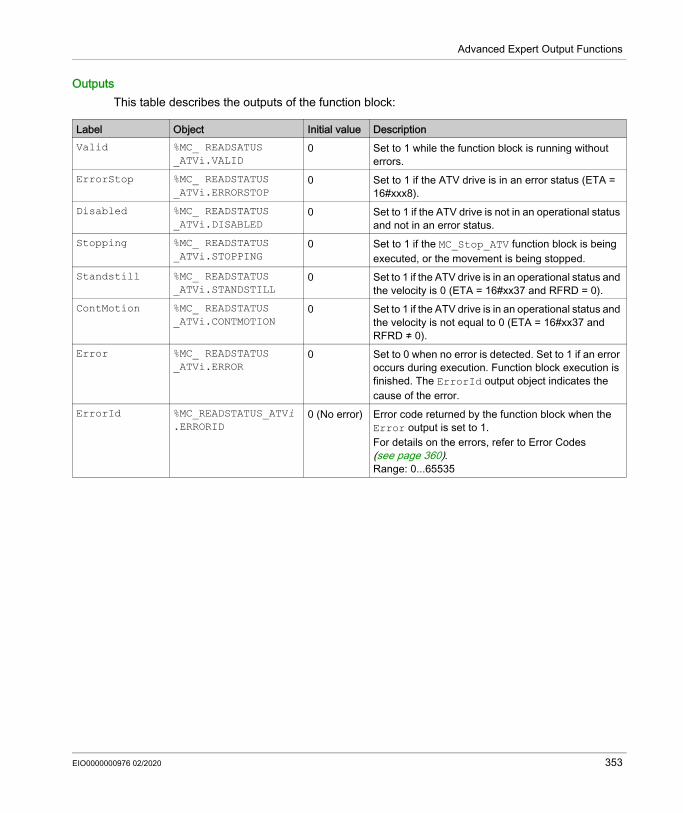
Advanced Expert Output Functions
OutputsThis table describes the outputs of the function block:
Label Object Initial value DescriptionValid %MC_ READSATUS
_ATVi.VALID0 Set to 1 while the function block is running without
errors.ErrorStop %MC_ READSTATUS
_ATVi.ERRORSTOP0 Set to 1 if the ATV drive is in an error status (ETA =
16#xxx8).Disabled %MC_ READSTATUS
_ATVi.DISABLED0 Set to 1 if the ATV drive is not in an operational status
and not in an error status.Stopping %MC_ READSTATUS
_ATVi.STOPPING0 Set to 1 if the MC_Stop_ATV function block is being
executed, or the movement is being stopped.Standstill %MC_ READSTATUS
_ATVi.STANDSTILL0 Set to 1 if the ATV drive is in an operational status and
the velocity is 0 (ETA = 16#xx37 and RFRD = 0).ContMotion %MC_ READSTATUS
_ATVi.CONTMOTION0 Set to 1 if the ATV drive is in an operational status and
the velocity is not equal to 0 (ETA = 16#xx37 and RFRD ≠ 0).
Error %MC_ READSTATUS _ATVi.ERROR
0 Set to 0 when no error is detected. Set to 1 if an error occurs during execution. Function block execution is finished. The ErrorId output object indicates the cause of the error.
ErrorId %MC_READSTATUS_ATVi.ERRORID
0 (No error) Error code returned by the function block when the Error output is set to 1. For details on the errors, refer to Error Codes (see page 360).Range: 0...65535
EIO0000000976 02/2020 353
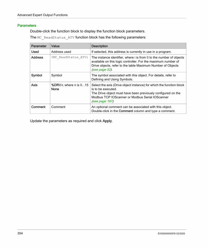
Advanced Expert Output Functions
ParametersDouble-click the function block to display the function block parameters.The MC_ReadStatus_ATV function block has the following parameters:
Update the parameters as required and click Apply.
Parameter Value DescriptionUsed Address used If selected, this address is currently in use in a program.Address %MC_ReadStatus_ATVi The instance identifier, where i is from 0 to the number of objects
available on this logic controller. For the maximum number of Drive objects, refer to the table Maximum Number of Objects (see page 52).
Symbol Symbol The symbol associated with this object. For details, refer to Defining and Using Symbols.
Axis %DRVn, where n is 0...15None
Select the axis (Drive object instance) for which the function block is to be executed. The Drive object must have been previously configured on the Modbus TCP IOScanner or Modbus Serial IOScanner (see page 187).
Comment Comment An optional comment can be associated with this object.Double-click in the Comment column and type a comment.
354 EIO0000000976 02/2020

Advanced Expert Output Functions
MC_ReadMotionState_ATV: Read Motion State
DescriptionThis function block outputs status information on the movement read from the ATV drive.
Graphical Representation
InputsThis table describes the inputs of the function block:
Input Object Initial Value
Description
Enable - 0 Set to 1 to start execution of the function block.Axis %MC_READMOTIONSTATE_ATVi.AXIS
where i is 0...15- Identifier of the axis (%DRV0...%DRV15) for which
the function block is to be executed.
EIO0000000976 02/2020 355

Advanced Expert Output Functions
OutputsThis table describes the outputs of the function block:
NOTE: When the speed command of the ATV drive is low (< 10), the InVel and ConstantVel parameters may be invalid because the speed range of the ATV drive itself may be inaccurate.
Output Object Initial Value
Description
Valid %MC_ READMOTIONSTATE _ATVi.VALID
0 Set to 1 while the function block is running without errors.
ConstantVel %MC_ READMOTIONSTATE _ATVi.CONSTANTVEL
0 Set to 1 when a movement at constant velocity is being performed (ETA register).
Accelerating %MC_ READMOTIONSTATE _ATVi.ACCELERATING
0 Set to 1 when the motor is accelerating (ETI register).
Decelerating %MC_ READMOTIONSTATE _ATVi.DECELERATING
0 Set to 1 when the motor is decelerating (ETI register).
Error %MC_ READMOTIONSTATE _ATVi.ERROR
0 Set to 0 when no error is detected. Set to 1 if an error occurs during execution. Function block execution is finished. The ErrorId output object indicates the cause of the error.
ActualVel %MC_READMOTIONSTATE_ATVi.ACTUALVEL
0 Velocity returned by the ATV drive (RFRD register).Range: -32768...32767
AxisErrorId %MC_READMOTIONSTATE_ATVi.AXISERRORID
0 Axis error identifier returned by the ATV drive (DP0 register). There is an axis error when the drive is in an error status. Set to 0 if the drive is not in an error status (ETA register ≠ 16#xxx8)For details on axis errors, refer to AxisErrorId Error Codes (see page 360).Range: -32768...32767
ErrorId %MC_READMOTIONSTATE_ATVi.ERRORID
No error (nOF)
Error code returned by the function block when the Error output is set to 1. For details on the errors, refer to Error Codes (see page 360).Range: 0...65535
356 EIO0000000976 02/2020

Advanced Expert Output Functions
ParametersDouble-click the function block to display the function block parameters.The MC_ReadMotionState_ATV function block has the following parameters:
Update the parameters as required and click Apply.
Parameter Value DescriptionUsed Address used If selected, this address is currently in use in a
program.Address %MC_ReadMotionState_ATVi The instance identifier, where i is from 0 to the number
of objects available on this logic controller. For the maximum number of Drive objects, refer to the table Maximum Number of Objects (see page 52).
Symbol Symbol The symbol associated with this object. For details, refer to Defining and Using Symbols.
Axis %DRVn, where n is 0...15None
Select the axis (Drive object instance) for which the function block is to be executed. The Drive object must have been previously configured on the Modbus TCP IOScanner or Modbus Serial IOScanner (see page 187).
Comment Comment An optional comment can be associated with this object.Double-click in the Comment column and type a comment.
EIO0000000976 02/2020 357

Advanced Expert Output Functions
MC_Reset_ATV: Acknowledge and Reset Error
DescriptionThis function block is used to acknowledge an error and re-initialize the error condition on the drive. For more information, refer to Drive State Diagram (see page 337).
Graphical Representation
InputsThis table describes the inputs of the function block:
Label Object Initial value DescriptionExecute - 0 Set to 1 to start execution of the function block.Axis %MC_RESET_ATVi.AXIS
where i is 0...15- Identifier of the axis (%DRV0...%DRV15) for which the
function block is to be executed.
358 EIO0000000976 02/2020

Advanced Expert Output Functions
OutputsThis table describes the outputs of the function block:
ParametersDouble-click the function block to display the function block parameters.The MC_Reset_ATV function block has the following parameters:
Update the parameters as required and click Apply.
Output Output Object Initial Value
Description
Done %MC_RESET_ATVi.DONE 0 Set to 1 when Reset has ended without error.Busy %MC_RESET_ATVi.BUSY 0 Set to 1 when the function block begins execution.Error %MC_RESET_ATVi.ERROR 0 Set to 1 if the device remains in an error status
after timeout expiration. The timeout is calculated as the channel cycle time multiplied by 4, or 200 ms, whichever is greater. A minimum of 200 ms is required to allow for drive reaction time.Refer to Configuring Channels (see page 193) for information on the configuring the channel cycle time.
ErrorId %MC_RESET_ATVi.ERRORID 0 (No error)
Error code returned by the function block when the Error output is set to 1. For details on the errors, refer to Error Codes (see page 360).Range: 0...65535
Parameter Value DescriptionUsed Address used If selected, this address is currently in use in a program.Address %MC_Reset_ATVi The instance identifier, where i is from 0 to the number of
objects available on this logic controller. For the maximum number of Drive objects, refer to the table Maximum Number of Objects (see page 52).
Symbol Symbol The symbol associated with this object. For details, refer to Defining and Using Symbols.
Axis %DRVn, where n is 0...15None
Select the axis (Drive object instance) for which the function block is to be executed. The Drive object must have been previously configured on the Modbus TCP IOScanner or Modbus Serial IOScanner (see page 187).
Comment Comment An optional comment can be associated with this object.Double-click in the Comment column and type a comment.
EIO0000000976 02/2020 359

Advanced Expert Output Functions
Error Codes
ErrorId Error CodesThis table lists the possible function block error codes:
AxisErrorId Error CodesThis table lists the possible function block axis error codes returned by the MC_ReadMotion-Status function block:
Value Name Description0 No error No error detected.1 IOScanner error Error detected on IOScanner (1).2 ATV is in an error status The ATV drive is in an error status (ETA = 16#xxx8).3 Timeout error Timeout expired before the MC_Power_ATV function
block has received the correct status from the drive.4 Invalid ATV status The ATV drive has an invalid ETA value.5 Reset error The MC_Reset_ATV function block is requested while
the ATV drive is in an error status.6 Stop Active error The MC_Jog_ATV or MV_MoveVelocity_ATV
function block is requested while MC_Stop is active.
7 ATV Not Run error The MC_Jog_ATV or MV_MoveVelocity_ATV function block is requested while the ATV drive is not operational.
8 Invalid AxisRef error AxisRef input %DRV of the function block is invalid (not present in the Modbus TCP IOScanner or Modbus Serial IOScanner configuration (see page 177)).
9 Internal error A firmware error occurred. (1) Only for Modbus TCP IOScanner.If the %MC_Power_ATV function block raises an IOScanner error while the device is being scanned, it may be due to an overload on the Ethernet network. To identify the cause of the error, you can: Verify the IOScanner state: %SW212 (see page 254). Verify the drive state: %IWNS (300+x) (see page 239). Verify the channel state: %IWNS (300+x).y (see page 239). Increase the Response timeout of the drive (see page 146).
Value Name0 No error (nOF)2 EEPROM control (EEF1)3 Incorrect configuration (CFF)4 Invalid Configuration (CFI)
360 EIO0000000976 02/2020

Advanced Expert Output Functions
5 Modbus Comm Interruption (SLF1)6 Internal Link Error (ILF)7 Fieldbus Com Interrupt (CnF)8 External Error (EPF1)9 Overcurrent (OCF)10 Precharge Capacitor (CrF)13 AI2 4-20 mA loss (LFF2)15 Input Overheating (IHF)16 Drive Overheating (OHF)17 Motor Overload (OLF)18 DC Bus Overvoltage (ObF)19 Supply Mains Overervoltage (OSF) 20 Single Output Phase Loss (OPF1) 21 Input phase loss (PHF)22 Supply Mains Undervoltage (USF) 23 Motor Short Circuit (SCF1)24 Motor Overspeed (SOF)25 Autotuning Error26 Internal Error 1 (InF1)27 Internal Error 2 (InF2)28 Internal Error 3 (InF3)29 Internal Error 4 (InF4)30 EEPROM ROM Power (EEF2)32 Ground Short Circuit (SCF3)33 Output Phase Loss (OPF2)37 Internal Error (InF7)38 Fieldbus Error (EPF2)40 Internal Error 8 (InF8)42 PC Com Interruption (SLF2)45 HMI Com Interruption (SLF3)51 Internal Error 9 (InF9)52 Internal Error 10 (InFA)53 Internal Error 11 (InFb)54 IGBT Overheating (tJF)
Value Name
EIO0000000976 02/2020 361

Advanced Expert Output Functions
55 IGBT Short Circuit (SCF4)56 Motor Short Circuit (SCF5)60 Internal Error 12 (InFC)64 Input Contactor (LCF)68 Internal Error 6 (InF6)69 Internal Error 14 (InFE)71 AI3 4-20mA Loss (LFF3)72 AI4 4-20mA Loss (LFF4)73 Boards Compatibility (HCF)77 Conf Transfer Error (CFI2)79 AI5 4-20mA Loss (LFF5)99 Channel Switch Error (CSF)100 Process Underload (ULF)101 Process Overload (OLC)105 Angle Error (ASF)106 AI1 4-20mA Loss (LFF1)107 Safety Function Error (SAFF)110 AI2 Th Detected Error (tH2F)111 AI2 Thermal Sensor Error (t2CF)112 AI3 Th Detected Error (tH3F)113 AI3 Thermal Sensor Error (t3CF)114 Pump Cycle Start Error (PCPF)119 Pump Low Flow Error (PLFF)120 AI4 Th Detected Error (tH4F)121 AI4 Thermal Sensor Error (t4CF)122 AI5 Th Detected Error (tH5F)123 AI5 Thermal Sensor Error (t5CF)126 Dry Run Error (drYF)127 PID Feedback Error (PFMF)128 Program Loading Error (PGLF)129 Program Running Error (PGrF)130 Lead Pump Error (MPLF)131 Low Level Error (LCLF)132 High Level Error (LCHF)
Value Name
362 EIO0000000976 02/2020

Advanced Expert Output Functions
142 Internal Error 16 (InFG)143 Internal Error 17 (InFH)144 Internal Error 0 (InF0)146 Internal Error 13 (InFd)149 Internal Error 21 (InFL)151 Internal Error 15 (InFF)152 Firmware Update Error (FEr)153 Internal Error 22 (InFM)154 Internal Error 25 (InFP)155 Internal Error 20 (InF)157 Internal Error 27 (InFr)
Value Name
EIO0000000976 02/2020 363

Advanced Expert Output Functions
Pulse Train Output (%PTO)
Section 7.4Pulse Train Output (%PTO)
OverviewThis chapter provides descriptions and programming guidelines for using Pulse Train Output function blocks.
What Is in This Section?This section contains the following topics:
Topic PagePulse Train Output (PTO) 365Pulse Output Modes 368Acceleration / Deceleration Ramp 370Probe Event 373Backlash Compensation 376Positioning Limits 378
364 EIO0000000976 02/2020

Advanced Expert Output Functions
Pulse Train Output (PTO)
IntroductionThe M221 PTO function provides pulse train output channels for a specified number of pulses and a specified velocity (frequency). The PTO function is used to control the positioning or speed of independent linear single-axis stepper or servo drives in open loop mode. The PTO function does not have any position feedback information from the process. Therefore, position information must be integrated in the drive.The PLS (pulse), PWM (pulse width modulation), PTO (pulse train output), and FREQGEN (frequency generator) functions use the same dedicated outputs. Only one of these four functions can be used on the same channel.A PTO channel can use optional interface signals for homing (Ref), event (Probe), limits (LimP, LimN), or drive interface (DriveReady, DriveEnable).Automatic origin offset and backlash compensation are also managed to improve positioning accuracy. Diagnostics are available for status monitoring.
Supported FunctionsThe PTO channels support the following functions: two output modes (two channels for Pulse and Direction or one channel for CW/CCW) single axis moves (velocity and position) relative and absolute positioning, with automatic direction management trapezoidal and S-curve acceleration and deceleration homing (four modes with offset compensation) dynamic acceleration, deceleration, velocity, and position modification switch from speed to position mode move queuing (buffer of one move) position capture and move trigger on event (using probe input) backlash compensation limits (hardware and software) diagnosticsNOTE: Motion function blocks (see page 418) and administrative function blocks (see page 451) help you to program these functions.
EIO0000000976 02/2020 365

Advanced Expert Output Functions
PTO CharacteristicsThere are up to five physical inputs for a PTO channel: Two are assigned to the PTO function through configuration and are taken into account upon a
rising edge on the input: Ref input Probe input
Three are assigned to the MC_Power_PTO (see page 423) function block. They have no fixed assignment (they are not configured in the configuration screen), and are read with all other inputs: DriveReady input Limit positive input Limit negative input
NOTE: These inputs are managed like any other regular input, but are used by the PTO function when assigned to MC_Power_PTO (see page 423) function block.
NOTE: The positive and negative limit inputs are required to help prevent over-travel.
There are up to three physical outputs for a PTO channel: Two outputs are mandatory to manage the output mode of the PTO function. They have a fixed
assignment and must be enabled by configuration: CW / CCW Pulse / Direction
The other output, DriveEnable, is associated with the MC_Power_PTO (see page 423) function block. It has no fixed assignment and is written at the end of the MAST cycle as regular outputs.
WARNINGUNINTENDED EQUIPMENT OPERATION Ensure that controller hardware limit switches are integrated in the design and logic of your
application. Mount the controller hardware limit switches in a position that allows for an adequate braking
distance.Failure to follow these instructions can result in death, serious injury, or equipment damage.
366 EIO0000000976 02/2020

Advanced Expert Output Functions
The PTO function has the following characteristics:
Characteristic ValueNumber of channels 2 or 4 depending on the moduleNumber of axis 1 per channelPosition range -2,147,483,648...2,147,483,647 (32 bits)Minimum velocity 0 HzMaximum velocity 100 kHz (for a 40/60 duty cycle and max. 200 mA)Minimum step 1 HzAccuracy on velocity 1 %Acceleration / deceleration (min) 1 Hz/msAcceleration / deceleration (max) 100 kHz/msOrigin offset -2,147,483,648...2,147,483,647 (32 bits)Software limits range -2,147,483,648...2,147,483,647 (32 bits)
EIO0000000976 02/2020 367

Advanced Expert Output Functions
Pulse Output Modes
OverviewThere are two possible output modes: ClockWise / CounterClockwise Pulse / Direction
ClockWise (CW) / CounterClockwise (CCW) ModeThis mode generates a signal that defines the motor operating speed and direction. This signal is implemented on the first PTO channel (PTO0 only).
NOTE: PTO1 is not available when choosing this mode.
Pulse / Direction ModeThis mode generates two signals on the PTO channels: The pulse output provides the motor operating speed (Pulses). The direction output provides the motor rotation direction (Direction).
NOTE: The direction output can be disabled if not needed for the application.
368 EIO0000000976 02/2020

Advanced Expert Output Functions
Special Cases
Special Case DescriptionEffect of a cold restart (%S0=TRUE) The axis is set to Disabled state.
The PTO function blocks are initialized.
Effect of a warm restart (%S1=TRUE)
The axis is set to Disabled state. The PTO function blocks are initialized.
Effect at controller stop The axis is set to ErrorStop state. The outputs are reset to 0.
Effect of online modification None
EIO0000000976 02/2020 369

Advanced Expert Output Functions
Acceleration / Deceleration Ramp
Start VelocityThe Start Velocity is the minimum frequency at which a stepper motor can produce movement, with a load applied, without the loss of steps. Start Velocity parameter is used when starting a motion from velocity 0.Start Velocity must be in the range 0...MaxVelocityAppl.
Value 0 means that the Start Velocity parameter is not used. In this case, the motion starts at a velocity = acceleration rate x 1 ms.
Stop VelocityThe Stop Velocity is the maximum frequency at which a stepper motor stops producing movement, with a load applied, without loss of steps. Stop Velocity is only used when moving from a higher velocity than Stop Velocity, down to velocity 0.Stop Velocity must be in the range 0...MaxVelocityAppl.
Value 0 means that the Stop Velocity parameter is not used. In this case, the motion stops at a velocity = deceleration rate x 1 ms.
Acceleration / DecelerationAcceleration is the rate of velocity change, starting from Start Velocity to target velocity. Deceleration is the rate of velocity change, starting from target velocity to Stop Velocity. These velocity changes are implicitly managed by the PTO function in accordance with Acceleration, Deceleration and JerkRatio parameters following a trapezoidal or an S-curve profile.
Acceleration / Deceleration Ramp with a Trapezoidal ProfileWhen the jerk ratio parameter is set to 0, the acceleration / deceleration ramp has a trapezoidal profile.Expressed in Hz/ms, the acceleration and deceleration parameters represent the rate of velocity change.
370 EIO0000000976 02/2020

Advanced Expert Output Functions
Acceleration / Deceleration Ramp with an S-curve Profile When the jerk ratio parameter is greater than 0, the acceleration / deceleration ramp has an S-curve profile.The S-curve ramp is used in applications controlling high inertia, or in those that manipulate fragile objects or liquids. The S-curve ramp enables a smoother and progressive acceleration / deceleration, as demonstrated in the following graphics:
JerkRatio 0%: Constant acceleration / deceleration.
JerkRatio 66%: 2/3 of the acceleration and deceleration time is spent in increasing and decreasing the acceleration and deceleration value.
JerkRatio 100%: The entire time is spent in increasing and decreasing the acceleration and deceleration value.
EIO0000000976 02/2020 371

Advanced Expert Output Functions
NOTE: The JerkRatio parameter value is common for acceleration and deceleration so that concave time and convex time are equal.
Affect of the S-Curve Ramp on Acceleration / DecelerationThe duration for the acceleration / deceleration is maintained, whatever the JerkRatio parameter may be. To maintain this duration, the acceleration or deceleration is other than that configured in the function block (Acceleration or Deceleration parameters).
When the JerkRatio is applied, the acceleration / deceleration is affected.
When the JerkRatio is applied at 100%, the acceleration / deceleration is two times that of the configured Acceleration/Deceleration parameters.
NOTE: If the JerkRatio parameter value is invalid, the value is re-calculated to respect the MaxAccelerationAppl and MaxDecelerationAppl parameters.JerkRatio is invalid when: its value is greater than 100. In this case, a Jerkratio of 100 is applied. its value is less than 0. In this case, a Jerkratio of 0 is applied.
372 EIO0000000976 02/2020

Advanced Expert Output Functions
Probe Event
DescriptionThe Probe input is enabled by configuration, and activated using the MC_TouchProbe_PTO function block.The Probe input is used as an event to: capture the position, start a move independently of the task.Both functions can be active at the same time, that is, the same event captures the position and start a motion function block (see page 365).NOTE: Only the first event after the rising edge at the MC_TouchProbe_PTO function block Busy output is valid. Once the Done output is set to TRUE, subsequent events are ignored. The function block needs to be reactivated to respond to other events.
Position CaptureThe position captured is available in %MC_TouchProbe_PTO.RecordedPos.
Motion TriggerThe BufferMode input of a motion function block must be set to seTrigger.
This example illustrates a change target velocity with enable window:
1 Capture the position counter value2 Trigger Move Velocity function block
EIO0000000976 02/2020 373

Advanced Expert Output Functions
This example illustrates a move of pre-programmed distance, with simple profile and no enable window:
1 Capture the position counter value2 Trigger Move Relative function block
This example illustrates a move of pre-programmed distance, with complex profile and enable window:
1 Capture the position counter value2 Trigger Move Relative function block
374 EIO0000000976 02/2020

Advanced Expert Output Functions
This example illustrates a trigger event out of enable window:
EIO0000000976 02/2020 375

Advanced Expert Output Functions
Backlash Compensation
DescriptionThe Backlash Compensation parameter is defined as the amount of motion needed to compensate for the mechanical clearance in gears (backlash) when a movement is reversed:
NOTE: The function does not take into account external sources of movement, such as inertia movement or other forms of induced movement.Backlash compensation is set in number of pulses (0...65535, default value is 0). When set, at each direction reversal, the specified number of pulses is first emitted at start velocity, and then the programmed movement is executed. The backlash compensation pulses are not added to the position counter.
376 EIO0000000976 02/2020

Advanced Expert Output Functions
This figure illustrates the backlash compensation:
NOTE: Before the initial movement is started, the function cannot determine the amount of backlash to
compensate for. Therefore, the backlash compensation is only active after a first move is performed and the compensation is applied at the first direction reversal.
If an aborting command is received or an error detected before the backlash completion, the absolute position remains unchanged.
After an abort command, the backlash resumes from current backlash position when a new move is started.
For more details, refer to the Configuring Pulse Train Output (see page 122).
EIO0000000976 02/2020 377

Advanced Expert Output Functions
Positioning Limits
IntroductionPositive and negative limits can be set to control the movement boundaries in both directions. Both hardware and software limits are managed by the controller. Hardware and software limit switches are used to manage boundaries in the controller application only. They are not intended to replace any functional safety limit switches wired to the drive. The controller application limit switches must necessarily be activated before the functional safety limit switches wired to the drive. In any case, the type of functional safety architecture, which is beyond the scope of the present document, that you deploy depends on your safety analysis, including, but not limited to: risk assessment according to EN/ISO 12100 FMEA according to EN 60812
The figure illustrates hardware and software limit switches:
WARNINGUNINTENDED EQUIPMENT OPERATIONEnsure that a risk assessment is conducted and respected according to EN/ISO 12100 during the design of your machine.Failure to follow these instructions can result in death, serious injury, or equipment damage.
378 EIO0000000976 02/2020

Advanced Expert Output Functions
Once either the controller hardware or software limits are crossed, an error is detected and a Fast stop deceleration is performed: the axis switches to ErrorStop state, with AxisErrorId 1002 to 1005. Refer to MC_ReadAx-
isError_PTO (see page 460) and Axis Control Advisory Alerts (see page 410). the current direction becomes invalid and the associated PTO parameter EnableDirPos
(1004) or EnableDirNeg (1005) is reset to 0 by the system. the function block under execution detects the error state, on other applicable function blocks, the CmdAborted outputs are set to TRUE.
To clear the axis error state, and return to a Standstill state, execution of MC_Reset_PTO is required as any motion command will be rejected (refer to PTO parameters (see page 409) EnableDirPos or EnableDirNeg) while the axis remains outside the limits (function block terminates with ErrorId=InvalidDirectionValue). It is only possible to execute a motion command in the opposite direction under these circumstances.Once the axis is inside the limits, the EnableDirPos or EnableDirNeg parameter is restored to 1 (valid) by the system.
NOTE: In previous diagram, the axis move back in the limits is the result of the execution of MC_Reset_PTO (it is not performed automatically).
Software LimitsSoftware limits can be set to control the movement boundaries in both directions.Limit values are enabled and set in the configuration screen, such that: Positive limit > Negative limit Values in the range -2,147,483,648 to 2,147,483,647They can also be enabled, disabled, or modified in the application program (MC_WritePar_PTO and PTO Parameter (see page 409)).NOTE: When enabled, the software limits are valid after an initial homing is successfully performed (that is, the axis is homed, MC_Home_PTO).
EIO0000000976 02/2020 379
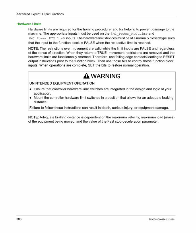
Advanced Expert Output Functions
Hardware LimitsHardware limits are required for the homing procedure, and for helping to prevent damage to the machine. The appropriate inputs must be used on the %MC_Power_PTO.LimP and %MC_Power_PTO.LimN inputs. The hardware limit devices must be of a normally closed type such that the input to the function block is FALSE when the respective limit is reached. NOTE: The restrictions over movement are valid while the limit inputs are FALSE and regardless of the sense of direction. When they return to TRUE, movement restrictions are removed and the hardware limits are functionnally rearmed. Therefore, use falling edge contacts leading to RESET output instructions prior to the function block. Then use those bits to control these function block inputs. When operations are complete, SET the bits to restore normal operation.
NOTE: Adequate braking distance is dependent on the maximum velocity, maximum load (mass) of the equipment being moved, and the value of the Fast stop deceleration parameter.
WARNINGUNINTENDED EQUIPMENT OPERATION Ensure that controller hardware limit switches are integrated in the design and logic of your
application. Mount the controller hardware limit switches in a position that allows for an adequate braking
distance.Failure to follow these instructions can result in death, serious injury, or equipment damage.
380 EIO0000000976 02/2020

Advanced Expert Output Functions
Configuration
Section 7.5Configuration
OverviewThis section describes how to configure a PTO channel and the associated parameters.
What Is in This Section?This section contains the following topics:
Topic PagePTO Configuration 382Motion Task Table 383
EIO0000000976 02/2020 381

Advanced Expert Output Functions
PTO Configuration
OverviewTo configure the Pulse Generator resource, refer to the Modicon M221 Logic Controller Programming Guide, Configuring Pulse Generators (see page 116).To configure the Pulse Generator resource as a PTO, refer to the Modicon M221 Logic Controller Programming Guide, PTO Configuration (see page 117).
382 EIO0000000976 02/2020

Advanced Expert Output Functions
Motion Task Table
OverviewThe Motion Task Table is a programming possibility for motion function blocks, dedicated to repetitive motion sequences. A sequence of movements is defined for an axis at configuration time (a sequence can be compared as a recipe that mixes various movements).The Motion Task Table can be dedicated to several axes and offers a graphical overview of the configured motion sequence.Use the MC_MotionTask_PTO function block to execute a Motion Task Table. When the table is called by the MC_MotionTask_PTO function block, it needs to be associated to a specific axis. The Motion Task Table is applied to the axis used by the MC_MotionTask_PTO function block. Several MC_MotionTask_PTO function blocks can execute the same %MT Motion Task Table instances simultaneously.
FeaturesThe maximum number of Motion Task Table (%MT) instances is 4.A Motion Task Table contains a sequence of single-axis movements: A sequence is a succession of steps. Each step defines the parameters of a movement. Each step uses a dedicated motion function block instance.Movements that can be used in the Motion Task Table: Move absolute Move relative Halt Set position Move velocity
Configuring a Motion Task TableThe Motion Task Table Assistant allows you to configure each movement in an ordered sequence and visualize an estimated global movement profile.
EIO0000000976 02/2020 383

Advanced Expert Output Functions
To display the Motion Task Table Assistant, proceed as follows:
Motion Task Table properties window description:
Step Action1 Select the Programming → Tools module tab and click PTO objects → Motion Task Tables in the
hardware tree to display the Motion Task Table properties.
2 Click [...] to configure the Motion Task Table.
Parameter Editable Value Default Value DescriptionConfigured No True/False False Indicates whether the Motion Task Table
contains configured steps.Address No %MTx %MTx Displays the address of the
Motion Task Table where x is the table number.
Symbol Yes – – Allows you to specify a symbol to associate with the Motion Task Table.Double-click the cell to edit the field.
Configuration Yes [...](Button)
Enabled Allows you to configure the sequence of movements using the Motion Task Table Assistant.
Comment Yes – – Allows you to specify a comment to associate with the Motion Task Table.Double-click the cell to edit the field.
384 EIO0000000976 02/2020

Advanced Expert Output Functions
Motion Task Table Assistant:
EIO0000000976 02/2020 385

Advanced Expert Output Functions
Motion Task Table Assistant main areas:• Steps : lists the sequence of single axis movements and input parameters for each movement.• Motion overview : click the refresh button, or F5, to generate a graphical view of the movement
implemented by the steps sequence.The curve provides a general overview of the movement. The curve is based on the following assumptions: Initial position is 0. Position limits are not enabled. Axis default motion configuration parameters are used. An event (probe input, POU) occurs after the step completion and a 100 ms delay. A %MWx delay is graphically represented by a 100 ms delay.
Steps window description:
Parameter Value Default Value
Description
Step 1...16 – Single axis movement number in the sequence.Type None
Move absoluteMove relativeHaltSet positionMove velocity
None Motion command.The motion command uses one motion function block instance indicated in the Software Objects parameter.
Pos See each software object function block parameter value.
empty The move parameters are the parameters of the software object assigned to the step.Parameter description: Pos: Position Distance: Distance Vel: Velocity Acc: Acceleration Dec: Deceleration Jerk ratio: Jerk ratio
NOTE: Vel parameter for the move velocity motion command is a combination of velocity and direction. In the table, the velocity range for the MC_MoveVel_PTO motion command is: - Max Velocity...+ Max Velocity. A negative velocity indicates a negative direction, a positive velocity indicates a positive direction.
DistanceVelAccDecJerk ratio
386 EIO0000000976 02/2020

Advanced Expert Output Functions
Next step Done / In velocity,Blending previous,Probe input event,SW event,Delay
empty The condition that needs to be fulfilled to proceed to the next step in the table sequence.Condition description: Done / In velocity: Done: Proceed to the next step when the present
step is completed.This parameter is available for the different motion commands except move velocity.
In velocity: Proceed to the next step when the requested velocity is reached.This parameter is only available for the move velocity motion command.
Blending previous: The velocity of next step is blended with the velocity at the end-position of this step.
Probe input event: Proceed to the next step when a defined event is detected on the Probe input.The edge is defined in the Event parameter.An input field opens in the bottom of the Steps window, Use probe event range, described in next table.NOTE: One occurrence of Probe input event can be used per Motion Task Table.
SW event: Proceed to the next step when the memory bit address (%Mx) set in the Event parameter is set to 1.
Delay: Proceed to the next step when the delay (starting at the beginning of the step) elapses. The delay is defined in the Delay parameter.
NOTE: When the Probe input event, or SW event, or Delay event occurs, the next step is started even if the present step is not completed.
Event –0/1%Mx
empty Event value complements the conditions described in Next step parameter.Next step choice and corresponding Event choice: Probe input event: 0: Falling edge 1: Rising edge
NOTE: The probe input event is independent of the application task cycle and the motion task cycle.
SW event: Memory bit %Mx.NOTE: %Mx is evaluated every 4 ms.
Parameter Value Default Value
Description
EIO0000000976 02/2020 387

Advanced Expert Output Functions
Delay 0...65535%MWx
empty Delay value represents the amount of time before proceeding to the next step. Depending on the .Next step parameter value, the Delay is evaluated from the beginning or the end of the step: Done / In velocity: The delay starts when the
present step is Done or In Velocity. Blending previous: Not available. Probe input event and SW event: The delay
starts at the beginning of the step. An elapsed delay generates a timeout if the event
did not occur, and next step is proceeded. If the event occurs before the end of the delay, the
next step is proceeded and the delay timeout is aborted.
NOTE: If Delay remains to its default value (0), the motion command waits for the probe input or software event to occur, without timeout.
Delay: The delay starts at the beginning of the step. The next step is proceeded when the delay is elapsed.
NOTE: An immediate value cannot be modified in an application POU, whereas, a %MWx value must be set by an application POU. The Motion Task Table Delay parameter is not modified if MC_ReadPar_PTO or MC_WritePar_PTO are set using ParNumber = 1000 (delay).
Software Objects
%MC_MOVEABS_PTOx%MC_MOVEREL_PTOx%MC_HALT_PTOx%MC_SETPOS_PTOx%MC_MOVEVEL_PTOx
empty Shows the software object allocated to the step. It is allocated by the system and is a read-only parameter. Those software objects are function block instances.
Symbol – empty Allows to specify a symbol to associate with the step software object.Double-click the cell to edit the field.
Parameter Value Default Value
Description
388 EIO0000000976 02/2020

Advanced Expert Output Functions
Use probe event range parameter in the Steps window:
Managing Step Parameters and EventThe parameters and event defined in a step are only valid at the start of the step execution, therefore: A step parameter value modified by the application is only valid if it is modified before the step
is active. The parameter can be modified using system allocated software object parameter in a POU.
A memory object value (%MW or %MWx) is only valid if updated before the step is active. An event is only evaluated once the step is active. In the case of a Probe input event, an
event occurring before the step is active cannot be detected.
Managing Function Block Instances Used in a Motion Task TableSystem allocated software object instances: cannot be used in an application POU to control an axis motion. Output parameters are not updated by the system during the execution of the
Motion Task Table. In other words, the output bits and output parameters are not valid. Input parameters: cannot be modified in the software object instance editor, or in the Programming tab. can be used to dynamically modify the Motion Task Table in an application POU. To
dynamically modify a system allocated software object instance input parameter, use the parameter address or its associated symbol.
Parameter Value Default Value DescriptionUse probe event range
True/False False When TRUE, a trigger event is only recognized within the position range defined between First position and Last position.The parameter can be modified if Next step is set to Probe input event in the Motion Task Table.
First position
- 2147483648... 2147483647%MDx
- 2147483648 NOTE: First position must be less than Last position.
Last position
- 2147483648... 2147483647%MDx
2147483647
Illustration of the position range influence on triggering is provided in the section on Probe Event (see page 373).NOTE: The position where the trigger event was detected is not recorded.
EIO0000000976 02/2020 389

Advanced Expert Output Functions
NOTE: The executing step can be modified but the modifications will not be taken into account until the next execution of the step.Example of movement described in a Motion Task Table: Step: 2 Movement type: Move relative Software object: %MC_MOVEREL_PTO1 Symbol: Move_Relative_Label2In previous example, the velocity input parameter can be modified by program using one of the following syntaxes: %MC_MOVEREL_PTO1.Vel Move_Relative_Label2.Vel
Management of the function block instances used in a Motion Task Table: When a Motion Task Table is configured, the reserved function block instances are set as Used. If all the instances of a specific function block are reserved, the associated move type cannot
be used anymore.
390 EIO0000000976 02/2020

Advanced Expert Output Functions
Programming
Section 7.6Programming
OverviewThis section lists the function blocks used to program the PTO function and describes how to add or remove those function blocks.
What Is in This Section?This section contains the following topics:
Topic PageAdding / Removing a Function Block 392PTO Function Blocks 394
EIO0000000976 02/2020 391

Advanced Expert Output Functions
Adding / Removing a Function Block
Adding a Function BlockFollow these steps to add an instance of a PTO function block:
Step Action1 Select the Programming tab.2 Select Function Blocks → PTO → Administrative or Function Blocks → PTO → Motion as shown in
the following graphic:
3 Click into the rung to place the selected function block.4 Associate the input/output variables of the function block.
392 EIO0000000976 02/2020
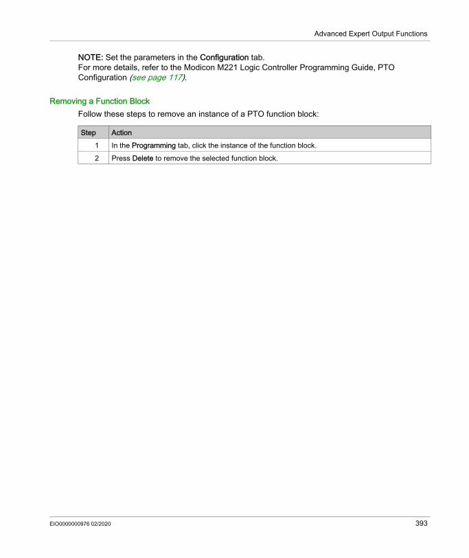
Advanced Expert Output Functions
NOTE: Set the parameters in the Configuration tab.For more details, refer to the Modicon M221 Logic Controller Programming Guide, PTO Configuration (see page 117).
Removing a Function BlockFollow these steps to remove an instance of a PTO function block:
Step Action1 In the Programming tab, click the instance of the function block.2 Press Delete to remove the selected function block.
EIO0000000976 02/2020 393

Advanced Expert Output Functions
PTO Function Blocks
Function BlocksThe PTO function is programmed in EcoStruxure Machine Expert - Basic using the following function blocks:
Category Function Block DescriptionMotion (single axis) (see page 418)
MC_MotionTask_PTO (see page 419)
Calls a Motion Task Table.
MC_Power_PTO (see page 423)
Enables power to the axis, switching the axis state from Disabled to Standstill. While the %MC_Power_PTO.Status bit is FALSE, no motion function block can be executed for that axis.
MC_MoveVel_PTO (see page 426)
Causes the specified axis to move at the specified speed, and transfer the axis to the state Continuous. This continuous movement is maintained until a software limit is reached, an aborting move is triggered, or a transition to ErrorStop state is detected.
MC_MoveRel_PTO (see page 431)
Moves the specified axis an incremental distance at the specified speed, and transfer the axis to the state Discrete.The target position is referenced from the current position at execution time, incremented by a distance.
MC_MoveAbs_PTO (see page 436)
Causes the specified axis to move towards a given position at the specified speed, and transfer the axis to the state Discrete.The function block terminates with Error set to TRUE if the axis is not Homed (no absolute reference position is defined). In this case, ErrorId is set to InvalidAbsolute.
MC_Home_PTO (see page 440)
Commands the axis to perform the sequence defining the absolute reference position, and transfers the axis to the state Homing (see page 396). The details of this sequence depend on Homing configuration parameters setting.
MC_SetPos_PTO (see page 443)
Modifies the coordinates of the axis without any physical movement.
MC_Stop_PTO (see page 445)
Commands a controlled motion stop and transfers the axis to the state Stopping. It aborts any ongoing move execution.
MC_Halt_PTO (see page 448)
Commands a controlled motion stop until the velocity is zero, and transfers the axis to the state Discrete. With the Done output set to TRUE, the state is transferred to Standstill.
394 EIO0000000976 02/2020

Advanced Expert Output Functions
NOTE: The motion function blocks act on the position of the axis according to the motion state diagram. The administrative function blocks do not influence the motion state.NOTE: The MC_Power_PTO (see page 423) function block is mandatory before a move command can be issued.
Administrative (see page 451)
MC_ReadActVel_PTO (see page 452)
Returns the value of the velocity of the axis.
MC_ReadActPos_PTO (see page 454)
Returns the value of the position of the axis.
MC_ReadSts_PTO (see page 456)
Returns the state diagram (see page 414) status of the axis.
MC_ReadMotionState_PTO (see page 458)
Returns the motion status of the axis.
MC_ReadAxisError_PTO (see page 460)
Returns an axis control error, if any.
MC_Reset_PTO (see page 462)
Resets all axis-related errors, conditions permitting to allow a transition from the states ErrorStop to Standstill. It does not affect the output of the function blocks instances.
MC_TouchProbe_PTO (see page 464)
Activates a trigger event on the probe input. This trigger event allows to record the axis position, and/or to start a buffered move.
MC_AbortTrigger_PTO (see page 467)
Aborts function blocks which are connected to trigger events (for example, MC_TouchProbe_PTO).
MC_ReadPar_PTO (see page 469)
Gets parameters from the PTO.
MC_WritePar_PTO (see page 471)
Writes parameters to the PTO.
WARNINGUNINTENDED EQUIPMENT OPERATION Do not use the same function block instance in different program tasks. Do not change the function block reference (AXIS) while the function block is executing.Failure to follow these instructions can result in death, serious injury, or equipment damage.
Category Function Block Description
EIO0000000976 02/2020 395

Advanced Expert Output Functions
Home Modes
Section 7.7Home Modes
OverviewThis section describes the PTO home modes.
What Is in This Section?This section contains the following topics:
Topic PageHoming Modes 397Position Setting 400Long Reference 401Short Reference No Reversal 403Short Reference Reversal 405Home Offset 407
396 EIO0000000976 02/2020

Advanced Expert Output Functions
Homing Modes
DescriptionHoming is the method used to establish the reference point or origin for absolute movement.A homing movement can be made using different methods. The M221 PTO channels provide several standard homing movement types: position setting (see page 400), long reference (see page 401), short reference reversal (see page 405), short reference no reversal (see page 403),A homing movement must be terminated without interruption for the new reference point to be valid. %MC_ReadSts_PTO.IsHomed is set to TRUE when a homing movement is finished
successfully. If the homing movement is interrupted, it needs to be started again. %MC_ReadSts_PTO.IsHomed is set to FALSE when the axis state is DISABLED, or when no
homing movement was finished successfully.Refer to MC_Home_PTO (see page 440) and home modes function block object codes (see page 409).
Home PositionHoming is done with an external switch and the homing position is defined on the switch edge. Then the motion is decelerated until stop.The actual position of the axis at the end of the motion sequence may therefore differ from the position parameter set on the function block:
REF (NO) Reference point (Normally Open)1 Position at the end of motion = %MC_HOME_PTO.Position + “deceleration to stop” distance.
EIO0000000976 02/2020 397

Advanced Expert Output Functions
To simplify the representation of a stop in the homing mode diagrams, the following presentation is made to represent the actual position of the axis:
REF (NO) Reference point (Normally Open)
LimitsHardware limits are necessary for the correct functioning of the MC_Home_PTO function block (Positioning Limits (see page 378) and MC_Power_PTO). Depending on the movement type you request with the homing mode, the hardware limits help assure that the end of travel is respected by the function block.When a homing action is initiated in a direction away from the reference switch, the hardware limits serve to either: indicate a reversal of direction is required to move the axis toward the reference switch or, indicate that an error has been detected as the reference switch was not found before reaching
the end of travel.For homing movement types that allow for reversal of direction, when the movement reaches the hardware limit the axis stops using the configured deceleration, and resumes motion in a reversed direction.In homing movement types that do not allow for the reversal of direction, when the movement reaches the hardware limit, the homing procedure is aborted and the axis stops with the Fast stop deceleration.
WARNINGUNINTENDED EQUIPMENT OPERATION Ensure that controller hardware limit switches are integrated in the design and logic of your
application. Mount the controller hardware limit switches in a position that allows for an adequate braking
distance.Failure to follow these instructions can result in death, serious injury, or equipment damage.
398 EIO0000000976 02/2020

Advanced Expert Output Functions
NOTE: Adequate braking distance is dependent on the maximum velocity, maximum load (mass) of the equipment being moved, and the value of the Fast stop deceleration parameter.
EIO0000000976 02/2020 399

Advanced Expert Output Functions
Position Setting
DescriptionIn the case of position setting, the current position is set to the specified position value. No move is performed.
400 EIO0000000976 02/2020

Advanced Expert Output Functions
Long Reference
Long Reference: Positive DirectionHomes to the reference switch falling edge in reverse direction.The initial direction of motion is dependent on the state of the reference switch:
REF (NO) Reference point (Normally Open)
EIO0000000976 02/2020 401

Advanced Expert Output Functions
Long Reference: Negative DirectionHomes to the reference switch falling edge in forward direction.The initial direction of motion is dependent on the state of the reference switch:
REF (NO) Reference point (Normally Open)
402 EIO0000000976 02/2020

Advanced Expert Output Functions
Short Reference No Reversal
Short Reference No Reversal: Positive DirectionHomes at low speed to the reference switch rising edge in forward direction, with no reversal:
REF (NO) Reference point (Normally Open)
REF (NO) Reference point (Normally Open)
EIO0000000976 02/2020 403

Advanced Expert Output Functions
Short Reference No Reversal: Negative DirectionHomes at low speed to the reference switch falling edge in reverse direction, with no reversal:
REF (NO) Reference point (Normally Open)
REF (NO) Reference point (Normally Open)
404 EIO0000000976 02/2020

Advanced Expert Output Functions
Short Reference Reversal
Short Reference Reversal: Positive DirectionHomes to the reference switch rising edge in forward direction.The initial direction of motion is dependent on the state of the reference switch:
REF (NO) Reference point (Normally Open)
REF (NO) Reference point (Normally Open)
EIO0000000976 02/2020 405

Advanced Expert Output Functions
Short Reference Reversal: Negative DirectionHomes to the reference switch rising edge in forward direction.The initial direction of motion is dependent on the state of the reference switch:
REF (NO) Reference point (Normally Open)
REF (NO) Reference point (Normally Open)
406 EIO0000000976 02/2020

Advanced Expert Output Functions
Home Offset
DescriptionIf the origin cannot be defined by switches with enough accuracy, it is possible to make the axis move to a specific position away from the origin switch. Home offset allows making a difference between mechanical origin and electrical origin. Home offset is set in number of pulses (-2,147,483,648...2,147,483,647, default value 0). When set by configuration, the MC_Home_PTO command is executed first, and then the specified number of pulses is output at the home low velocity in the specified direction.NOTE: The wait time between MC_Home_PTO command stop on origin switch and start of offset movement is fixed, set to 500 ms. The MC_Home_PTO command busy flag is only released after origin offset has been completed.
EIO0000000976 02/2020 407

Advanced Expert Output Functions
Data Parameters
Section 7.8Data Parameters
Function Block Object Codes
Direction This table lists the values for the direction function block object codes:
Buffer ModesThis table lists the values for the buffer modes function block object codes:
Name Value DescriptionmcPositiveDirection 1 CW, forward, positive (according to Output Mode
configuration setting).mcNegativeDirection -1 CCW, backward, reverse, negative (according to Output
Mode configuration setting).
Name Value DescriptionmcAborting 0 Start FB immediately (default mode).
Any ongoing motion is aborted. The move queue is cleared.mcBuffered 1 Start FB after current motion has finished (Done or InVel bit
is set to TRUE). There is no blending.mcBlendingPrevious 3 The velocity is blended with the velocity of the first FB
(blending with the velocity of FB1 at end-position of FB1).seTrigger 10 Start FB immediately when an event on the Probe input is
detected.Any ongoing motion is aborted. The move queue is cleared.
seBufferedDelay 11 Start FB after current motion has finished (Done or InVel output is set to TRUE) and the time delay has elapsed. There is no blending.The Delay parameter is set using MC_WritePar_PTO, with ParameterNumber 1000.
408 EIO0000000976 02/2020

Advanced Expert Output Functions
Homing ModesThis table lists the values for the homing modes function block object codes:
PTO ParameterThis table lists the values for the PTO parameters function block object codes:
Name Value DescriptionPositionSetting 0 Position.LongReference 1 Long reference.ShortReference_Reversal 20 Short reference.ShortReference_NoReversal 21 Short reference no reversal.
Name Parameter Number
R/W Description
CommandedPosition 1 R Commanded position.SWLimitPos (High Limit) 2 R/W Positive software position limit.
SWLimitNeg (Low Limit) 3 R/W Negative software position limit.
EnableLimitPos (Enable the Software Position Limits)
4 R/W Enable positive software limit switch (0...1).
EnableLimitNeg (Enable the Software Position Limits)
5 R/W Enable negative software limit switch (0...1).
MaxVelocityAppl (Max. Velocity)
9 R/W Maximal allowed velocity of the axis in the application (0...100,000).
ActualVelocity 10 R Velocity of the axis.CommandedVelocity 11 R Commanded velocity.MaxAccelerationAppl (Max. acc.)
13 R/W Maximal allowed acceleration of the axis in the application (0...100,000).
MaxDecelerationAppl (Max. dec.)
15 R/W Maximal allowed deceleration of the axis in the application (0...100,000).
Reserved 16 to 999 - Reserved for the PLCopen standard.Delay 1000 R/W Time in ms (0...65,535)
Default value: 0
EIO0000000976 02/2020 409

Advanced Expert Output Functions
PTO Axis Error CodesThis table lists the values for the PTO axis error codes:
EnableDirPos 1004 R/W Enable positive direction.When value = 0, the positive direction is not allowed on the axis. A move function block that would generate a move in a positive direction ends with InvalidDirectionValue error detected (3006). If there is an ongoing movement in the negative direction, and it is interrupted by a new move command in the positive direction, the error will be detected only at the end of the deceleration of the ongoing negative movement. Default value: 1
NOTE: A value change is only taken into account at the next move command or the next occurrence of velocity = 0.
EnableDirNeg 1005 R/W Enable negative direction.When value = 0, the negative direction is not allowed on the axis. A move function block that would generate a move in a negative direction ends with InvalidDirectionValue error detected (3006). If there is an ongoing movement in the positive direction, and it is interrupted by a new move command in the negative direction, the error will be detected only at the end of the deceleration of the ongoing positive movement. Default value: 1
NOTE: A value change is only taken into account at the next move command or the next occurrence of velocity = 0.
Name Parameter Number
R/W Description
Name Value DescriptionNoError 0 No error detected.Axis Control AlertsInternalError 1000 Motion controller internal error detected.DisabledAxis 1001 The move could not be started or has been aborted
because the axis is not ready.HwPositionLimitP 1002 Hardware positive position limit limP exceeded.HwPositionLimitN 1003 Hardware negative position limit limN exceeded.SwPositionLimitP 1004 Software positive position limit exceeded.
410 EIO0000000976 02/2020

Advanced Expert Output Functions
An Axis Control Alert switches the axis in ErrorStop state (MC_Reset_PTO is mandatory to get out of ErrorStop state). The resulting axis status is reflected by MC_ReadSts_PTO and MC_ReadAxisError_PTO.
PTO Motion Command Error CodesThis table lists the values for the PTO motion command error codes:
SwPositionLimitN 1005 Software negative position limit exceeded.ApplicationStopped 1006 Application execution has been stopped (controller in
STOPPED or HALT state).OutputProtection 1007 Short-circuit output protection is active on the PTO
channels. Refer to the description of %S10 and %SW139 in the Modicon M221 Logic Controller - Programming Guide, system bits (see page 242) and system words (see page 254).
OutputReset 1008 %S9 forced all outputs to be set to 0. Refer to System Bits (see page 241).
Axis Control AdvisoriesWarningVelocityValue 1100 Commanded Velocity parameter is out of range, therefore
velocity is limited to the configured maximum velocity.WarningAccelerationValue 1101 Commanded Acceleration parameter is out of range,
therefore acceleration is limited to the configured maximum acceleration.
WarningDecelerationValue 1102 Commanded Deceleration parameter is out of range, therefore deceleration is limited to the configured maximum deceleration.
WarningJerkRatioValue 1103 Commanded jerk ratio parameter is limited by the configured maximum acceleration or deceleration. In this case, the jerk ratio is recalculated to respect these maximums.
Name Value Description
Name Value DescriptionNoError 0 No error detected.Motion State Advisory AlertsErrorStopActive 2000 The move could not be started or has been aborted
because motion is prohibited by an ErrorStop condition.StoppingActive 2001 The move could not be started because motion is prohibited
by MC_Stop_PTO having control of the axis (either the axis is stopping, or MC_Stop_PTO.Execute input is held TRUE).
EIO0000000976 02/2020 411

Advanced Expert Output Functions
A Motion State Alert or a Range Alert does not affect the axis state, nor any move currently executing, nor the move queue. In this case, the error is only local to the applicable function block: the Error output is set to TRUE, and the ErrorId object output is set to the appropriate PTO motion command error code.
InvalidTransition 2002 Transition not allowed, refer to the Motion State Diagram.InvalidSetPosition 2003 MC_SetPos_PTO cannot be executed while the axis is
moving.HomingError 2004 Homing sequence cannot start on reference cam in this
mode.InvalidProbeConf 2005 The Probe input must be configured.InvalidHomingConf 2006 The Ref input must be configured for this homing mode.InvalidAbsolute 2007 An absolute move cannot be executed while the axis is not
successfully homed to an origin position. A homing sequence must be executed first (MC_Home_PTO).
MotionQueueFull 2008 The move could not be buffered because the motion queue is full.
InvalidTransitionMotionTask 2009 The motion task and the other motion function blocks linked to the same axis cannot be executed concurrently.
Range Advisory AlertsInvalidAxis 3000 The function block is not applicable for the specified axis.InvalidPositionValue 3001 Position parameter is out of limits, or distance parameter
gives an out of limits position.InvalidVelocityValue 3002 Velocity parameter is out of range.InvalidAccelerationValue 3003 Acceleration parameter is out of range.InvalidDecelerationValue 3004 Deceleration parameter is out of range.InvalidBufferModeValue 3005 Buffer mode does not correspond to a valid value.InvalidDirectionValue 3006 Direction does not correspond to a valid value, or direction
is invalid due to software position limit exceeded.InvalidHomeMode 3007 Homing mode is not applicable.InvalidParameter 3008 The parameter number does not exist for the specified axis.InvalidParameterValue 3009 Parameter value is out of range.ReadOnlyParameter 3010 Parameter is read-only.InvalidStepMotionTask 3011 Motion task step type is not defined.
Name Value Description
412 EIO0000000976 02/2020

Advanced Expert Output Functions
Operation Modes
Section 7.9Operation Modes
OverviewThis section describes the operation modes.
What Is in This Section?This section contains the following topics:
Topic PageMotion State Diagram 414Buffer Mode 416
EIO0000000976 02/2020 413

Advanced Expert Output Functions
Motion State Diagram
State DiagramThe axis is always in one of the defined states in this diagram:
Note 1 From any state, when an error is detected.Note 2 From any state except ErrorStop, when %MC_Power_PTO.Status = FALSE.Note 3 %MC_Reset_PTO.Done = TRUE and %MC_Power_PTO.Status = FALSE.Note 4 %MC_Reset_PTO.Done = TRUE and %MC_Power_PTO.Status = TRUE.Note 5 %MC_Power_PTO.Status = TRUE.Note 6 %MC_Stop_PTO.Done = TRUE and %MC_Stop_PTO.Execute = FALSE.
The table describes the axis states:
State DescriptionDisabled Initial state of the axis, no motion command is allowed. The axis is not homed.Standstill Power is on, no error is detected, and no motion commands are active on the axis.
Motion command is allowed.ErrorStop Highest priority, applicable when an error is detected on the axis or in the controller.
Any ongoing move is aborted by a Fast Stop Deceleration. Error output is set to TRUE on applicable function blocks, and an ErrorId sets the error code. As long as an error is pending, the state remains ErrorStop. No further motion command is accepted until a reset has been done using MC_Reset_PTO.
Homing Applicable when MC_Home_PTO controls the axis.Discrete Applicable when MC_MoveRel_PTO, MC_MoveAbs_PTO, or MC_Halt_PTO controls
the axis.
414 EIO0000000976 02/2020

Advanced Expert Output Functions
NOTE: Function blocks which are not listed in the state diagram do not affect a change of state of the axis.The entire motion command including acceleration and deceleration ramps cannot exceed 4,294,967,295 pulses. At the maximum frequency of 100 kHz, the acceleration and deceleration ramps are limited to 80 seconds.
Motion Transition TableThe PTO channel can respond to a new command while executing (and before completing) the current command according to the following table:
NOTE: When an error is detected in the motion transition, the axis goes into ErrorStop state. The ErrorId is set to InvalidTransition.
Continuous Applicable when MC_MoveVel_PTO controls the axis.Stopping Applicable when MC_Stop_PTO controls the axis.
State Description
Command NextHome MoveVel MoveRel MoveAbs Halt Stop
Current Standstill Allowed Allowed (1) Allowed (1) Allowed (1) Allowed Allowed
Home Rejected Rejected Rejected Rejected Rejected AllowedMoveVel Rejected Allowed Allowed Allowed Allowed AllowedMoveRel Rejected Allowed Allowed Allowed Allowed AllowedMoveAbs Rejected Allowed Allowed Allowed Allowed AllowedHalt Rejected Allowed Allowed Allowed Allowed AllowedStop Rejected Rejected Rejected Rejected Rejected Rejected
(1) When the axis is at standstill, for the buffer modes mcAborting/mcBuffered/mcBlendingPrevious, the move starts immediately.
Allowed the new command begins execution even if the previous command has not completed execution.Rejected the new command is ignored and results in the declaration of an error.
EIO0000000976 02/2020 415

Advanced Expert Output Functions
Buffer Mode
DescriptionSome of the motion function blocks have an input object called BufferMode. With this input object, the function block can either start immediately, start on probe event, or be buffered.The available options are defined in the buffer modes function block object codes (see page 408): An aborting motion (mcAborting) starts immediately, aborting any ongoing move, and clearing
the motion queue. An event motion (seTrigger) is an aborting move, starting on probe event (see page 373). A buffered motion (mcBuffered, mcBlendingPrevious, seBufferedDelay) is queued,
that is, appended to any moves currently executing or waiting to execute, and starts when the previous motion is done.
Motion Queue DiagramThe figure illustrates the motion queue diagram:
The buffer can contain only one motion function block.
416 EIO0000000976 02/2020

Advanced Expert Output Functions
The execution condition of the motion function block present in the buffer is: mcBuffered: when the current continuous motion is InVel, or when the current discrete
motion stops. seBufferedDelay: when the specified delay has elapsed, from the current continuous motion
is InVel, or from the current discrete motion stops. mcBlendingPrevious: when the position and velocity targets of current function block are
reached. The motion queue is cleared (all buffered motions are deleted): When an aborting move is triggered (mcAborting or seTrigger): CmdAborted output is set
to TRUE on buffered function blocks. When a MC_Stop_PTO function is executed: Error output is set to TRUE on cleared buffered
function blocks, with ErrorId=StoppingActive. When a transition to ErrorStop state is detected: Error output is set to TRUE on buffered
function blocks, with ErrorId=ErrorStopActive.
NOTE: Only a valid motion can be queued. If the function block execution terminates with the Error
output set to TRUE, the move is not queued, any move currently executing is not affected, and the queue is not cleared.
When the queue is already full, the Error output is set to TRUE on the applicable function block, and ErrorId output returns the error MotionQueueFull.
EIO0000000976 02/2020 417

Advanced Expert Output Functions
Motion Function Blocks
Section 7.10Motion Function Blocks
Overview This section describes the Motion function blocks.
What Is in This Section?This section contains the following topics:
Topic PageMC_MotionTask_PTO Function Block 419
MC_Power_PTO Function Block 423
MC_MoveVel_PTO Function Block 426
MC_MoveRel_PTO Function Block 431
MC_MoveAbs_PTO Function Block 436
MC_Home_PTO Function Block 440
MC_SetPos_PTO Function Block 443
MC_Stop_PTO Function Block 445
MC_Halt_PTO Function Block 448
418 EIO0000000976 02/2020

Advanced Expert Output Functions
MC_MotionTask_PTO Function Block
Function DescriptionBoth single movement motion function blocks and the Motion Task Table function block (MC_MotionTask_PTO) can be used for an axis.
However, the MC_MotionTask_PTO function block cannot be executed concurrently with another motion function block. If so, an error is detected and the ErrorId is set to InvalidTransition-MotionTask (2009) (see page 411).
Graphical Representation
NOTE: When you first enter the function block, you must configure it to use the intended axis and motion task
table. Double-click the function block to display the function block properties, choose the axis and table, then click Apply.
EIO0000000976 02/2020 419

Advanced Expert Output Functions
InputsThis table describes the inputs of the function block:
Input Initial Value
Description
Start FALSE On rising edge, starts the function block execution.The Loop and Pause inputs can be changed during the function block execution and they affect the ongoing execution.The Axis, Table, StartStep, and EndStep input objects values define the motion sequence when the rising edge occurs. A subsequent change in these input objects does not affect the ongoing execution.The outputs are set when the function block execution terminates.When FALSE: When the execution is ongoing (move is Busy and Active), outputs are
refreshed. When the execution is terminated, the outputs are reset one cycle later.
Loop FALSE When TRUE, once the function block execution terminates with no detected error, the motion task sequence starts again on StartStep. The Ended output is set for one cycle.The input is tested when the function block execution terminates with no detected error (Ended output is true).
Pause FALSE When TRUE: Active = 1 and Busy = 1 Forces the axis to the Halt state.
To reach the Halt state, the axis is decelerating in Discrete motion state, then the axis goes to the Standstill state when velocity = 0.
The Halt state is kept as long as the Pause input is TRUE. Keeps the Active output set even if velocity is equal to 0.
When reset to FALSE after being set to TRUE, the motion task execution resumes in the following conditions: The motion task resumes with the value of the ongoing velocity. The active step parameters are used. The absolute target position is not changed. If the motion task is a move
relative type, there is no distance added. In the step, the Next step condition is reset (for example: the delay is
restarted from 0, Probe input event is enabled and waiting for the configured edge).
420 EIO0000000976 02/2020

Advanced Expert Output Functions
This table describes the input objects of the function block:
OutputsThis table describes the outputs of the function block:
Input Object Type Initial Value
Description
Axis %PTOx – PTO axis instance for which the function block is to be executed. The parameter is set in the function block instance reached in the Programming → Tools module tab. Select the Axis parameter in PTO objects → Motion → MC_MotionTask_PTO → MC_MotionTask_PTO_properties dialog box.
Table %MT – Table instance for which the function block is to be executed. The parameter is set in the function block instance reached in the Programming → Tools module tab. Select the Table parameter in PTO objects → Motion → MC_MotionTask_PTO → MC_MotionTask_PTO_properties dialog box.
StartStep Byte 1 Step number that defines the first step executed in the Motion Task Table.The sequence is executed from StartStep to EndStep.Restriction: StartStep ≤ EndStep.
EndStep Byte 16 Step number that defines the last step executed in the Motion Task Table.The sequence is executed from StartStep to EndStep.Restriction: StartStep ≤ EndStep.
NOTE: If EndStep is greater than the maximum number of steps defined in the Motion Task Table, the last step of the table is used.
Output Initial Value DescriptionEnded 0 When TRUE, function block execution is finished with no error detected.
Ended output behavior: If the last step of the motion sequence is a discrete movement, the
output behaves like a Done output, the other outputs (Busy, Active, CmdAborted, Error) are reset to 0.
If the last step of the motion sequence is a continuous movement (move velocity), the output behaves like an InVel output.Other outputs behavior: Busy and Active are TRUE (1). CmdAborted and Error are FALSE (0).
If a loop is requested (Loop input), the Ended output is TRUE for one task cycle.
EIO0000000976 02/2020 421

Advanced Expert Output Functions
This table describes the output objects of the function block:
Operating ModesThe execution of a Motion Task Table called by MC MotionTask PTO function block complies with the motion state diagram (see page 414).MC_MotionTask_PTO start: The function block can only be started from Standstill state.
MC_MotionTask_PTO stop: The function block can be stopped by one of the following actions: Setting Pause input to TRUE. Executing a MC_Stop_PTOFunction block behavior on detected errors: If a motion state or range error is detected during the function block execution: A motion stop command is applied to the motion task using the present step deceleration
parameter value. If the step deceleration parameter is not valid, a fast stop deceleration is applied.
During the controlled motion stop, the function block outputs Active and Busy remain TRUE, with the output object ActiveStep = 0.
Once the motion is stopped, the function block execution is finished with Error = 1, and the ErrorId output object set to the value corresponding to the detected error type.
If an axis control error is detected, the axis switches to the ErrorStop state. The function block execution is finished with Error = 1, and ErrorId = 2000.
Busy - When TRUE, function block execution is in progress.When FALSE, execution of the function block has been terminated.
Active - When TRUE, the function block instance has control of the axis. Only one function block at a time can set Active TRUE for the same axis.
CmdAborted - When TRUE, function block execution is terminated due to another motion command (MC_Stop_PTO) or an axis error detected.
Error FALSE If TRUE, indicates that an error was detected. Function block execution is finished.
Output Object Type Initial Value DescriptionActiveStep Byte 0 Number of the step that is being executed in the
Motion Task Table.ErrorId Word NoError Motion command error codes, valid when Error
output is TRUE. Refer to PTO motion command error code table (see page 411).
Output Initial Value Description
422 EIO0000000976 02/2020

Advanced Expert Output Functions
MC_Power_PTO Function Block
BehaviorThe axis is disabled, when: %MC_Power_PTO.Enable = FALSE, or %MC_Power_PTO.DriveReady = FALSE, or an Hardware limit error is detected (HwPositionLimitP / HwPositionLimitN)
When the axis is disabled, then: the Axis switches from Standstill to Disabled state, or
from any ongoing move, to ErrorStop, and then Disabled state (when the error is reset). %MC_ReadSts_PTO.IsHomed is reset to 0 (a new homing procedure is required).
Graphical Representation
NOTE: When you first enter the function block, you must configure it to use the intended axis. Double-click on
the function block to display the function block properties, choose the axis and click Apply.
InputsThis table describes the inputs of the function block:
Input Initial Value
Description
Enable FALSE When TRUE, the function block is executed. The values of the other function block inputs can be modified continuously, and the function block outputs are updated continuously.When FALSE, terminates the function block execution and resets its outputs.
EIO0000000976 02/2020 423

Advanced Expert Output Functions
This table describes the input object of the function block:
OutputsThis table describes the outputs of the function block:
This table describes the output object of the function block:
DriveReady FALSE Signal from the drive indicating its readiness.Is set to TRUE when the drive is ready to start executing motion.If the drive signal is connected to the controller, use the appropriate controller input. If the drive does not provide this signal, you can force the value TRUE for this input with any TRUE boolean value.
LimP TRUE Hardware limit switch information, in positive direction.Is set to FALSE when the hardware limit switch is reached.If the hardware limit switch signal is connected to the controller, use the appropriate controller input. If this signal is not available, you can force the value TRUE for this input with any TRUE boolean value.
LimN TRUE Hardware limit switch information, in negative direction.Is set to FALSE when the hardware limit switch is reached.If the hardware limit switch signal is connected to the controller, use the appropriate controller input. If this signal is not available, you can force the value TRUE for this input with any TRUE boolean value.
Input Object Type Initial Value
Description
Axis PTOx - Instance for which the function block is to be executed. The name is declared in the controller configuration.
Input Initial Value
Description
Output Initial Value DescriptionStatus FALSE When TRUE, the drive is reported as ready to accept motion commands.DriveEnable FALSE When TRUE, indicates to the drive that it can accept motion commands
and that it should, therefore, enable power.If the drive input is connected to the controller, use the appropriate controller output. If the drive does not have an input for this signal, you can leave this function block output unused.
Error FALSE If TRUE, indicates that an error was detected. Function block execution is finished.
Output Object Type Initial Value DescriptionErrorId Word NoError Motion command error codes, valid when Error
output is TRUE. Refer to PTO motion command error code table (see page 411).
424 EIO0000000976 02/2020

Advanced Expert Output Functions
Timing Diagram ExampleThe diagram illustrates the operation of the MC_Power_PTO function block:
EIO0000000976 02/2020 425
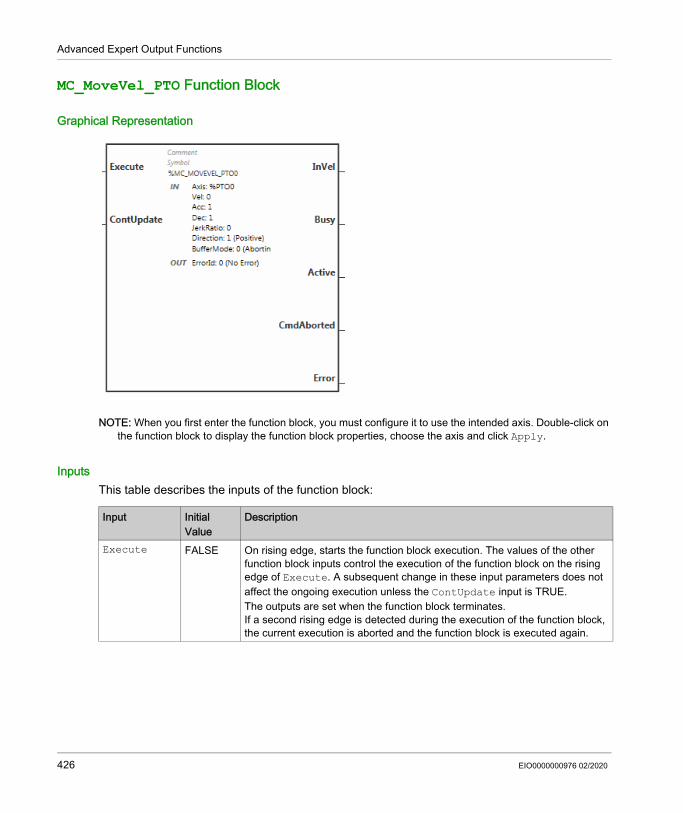
Advanced Expert Output Functions
MC_MoveVel_PTO Function Block
Graphical Representation
NOTE: When you first enter the function block, you must configure it to use the intended axis. Double-click on
the function block to display the function block properties, choose the axis and click Apply.
InputsThis table describes the inputs of the function block:
Input Initial Value
Description
Execute FALSE On rising edge, starts the function block execution. The values of the other function block inputs control the execution of the function block on the rising edge of Execute. A subsequent change in these input parameters does not affect the ongoing execution unless the ContUpdate input is TRUE.The outputs are set when the function block terminates.If a second rising edge is detected during the execution of the function block, the current execution is aborted and the function block is executed again.
426 EIO0000000976 02/2020

Advanced Expert Output Functions
This table describes the input objects of the function block:
ContUpdate FALSE When TRUE, makes the function block use any modified values of the input objects (Vel, Acc, Dec, and Direction), and apply it to the ongoing command.This input must be TRUE prior to the rising edge on the Execute input to be taken into account.
NOTE: A modification to the value of the Axis parameter is not taken into account. You must set Execute to 0 and then to 1 to change the Axis.
Input Object Type Initial Value DescriptionAxis PTOx - Instance for which the function block is to be
executed. The name is declared in the controller configuration.
Vel DINT 0 Target velocity.Range Hz: 0...MaxVelocityAppl (see page 409)
Acc DINT 0 Acceleration in Hz/msRange (Hz/ms): 1...MaxAccelerationAppl (see page 409)
Dec DINT 0 Deceleration in Hz/msRange (Hz/ms): 1...MaxDecelerationAppl (see page 409)
JerkRatio INT 0 Percentage of acceleration / deceleration adjustment used to create the S-curve profile (see page 371).Range: 0…100
Direction INT mcPositiveDirection Direction of the movement for PTO type CW/CCW forward (CW) = 1 (mcPositiveDirection)reverse (CCW) = -1 (mcNegativeDirection)
BufferMode INT mcAborting Transition mode from ongoing move. Refer to Buffer Modes table (see page 408).
Input Initial Value
Description
EIO0000000976 02/2020 427

Advanced Expert Output Functions
OutputsThis table describes the outputs of the function block:
This table describes the output object of the function block:
NOTE: To stop the motion, the function block has to be interrupted by another function block issuing a
new command. If a motion is ongoing, and the direction is reversed, first the motion is halted with the
deceleration of the MC_MoveVel_PTO function block, and then the motion resumes backward. The acceleration/deceleration duration of the segment block must not exceed 80 seconds.
Output Initial Value DescriptionInVel FALSE When TRUE, the target velocity has been reached.Busy - When TRUE, function block execution is in progress.
When FALSE, execution of the function block has been terminated.The function block must be kept in an active task of the application program for at least as long as Busy is TRUE.
Active - When TRUE, the function block instance has control of the axis. Only one function block at a time can set Active TRUE for the same axis.
CmdAborted - When TRUE, function block execution is terminated due to another motion command.
Error FALSE If TRUE, indicates that an error was detected. Function block execution is finished.
Output Object Type Initial Value DescriptionErrorId Word NoError Motion command error codes, valid when Error
output is TRUE. Refer to PTO motion command error code table (see page 411).
428 EIO0000000976 02/2020

Advanced Expert Output Functions
Timing Diagram ExampleThe diagram illustrates a simple profile from Standstill state:
The diagram illustrates a complex profile from Continuous state:
The diagram illustrates a complex profile from Continuous state with change of direction:
EIO0000000976 02/2020 429

Advanced Expert Output Functions
The diagram illustrates a complex profile from Discrete state:
430 EIO0000000976 02/2020

Advanced Expert Output Functions
MC_MoveRel_PTO Function Block
Graphical Representation
NOTE: When you first enter the function block, you must configure it to use the intended axis. Double-click on
the function block to display the function block properties, choose the axis and click Apply.
InputsThis table describes the input of the function block:
Input Initial Value
Description
Execute FALSE On rising edge, starts the function block execution. The values of the other function block inputs control the execution of the function block on the rising edge of Execute. A subsequent change in these input parameters does not affect the ongoing execution.The outputs are set when the function block terminates.
EIO0000000976 02/2020 431

Advanced Expert Output Functions
This table describes the input objects of the function block:
OutputsThis table describes the outputs of the function block:
Input Object Type Initial Value DescriptionAxis PTOx - Instance for which the function block is to be executed. The
name is declared in the controller configuration.Distance DINT 0 Relative distance for the motion, in pulses. The sign specifies
the direction.Vel DINT 0 Target velocity.
Range Hz: 0...MaxVelocityAppl (see page 409)Acc DINT 0 Acceleration in Hz/ms
Range (Hz/ms): 1...MaxAccelerationAppl (see page 409)Dec DINT 0 Deceleration in Hz/ms
Range (Hz/ms): 1...MaxDecelerationAppl (see page 409)JerkRatio INT 0 Percentage of acceleration / deceleration adjustment used to
create the S-curve profile (see page 371).Range: 0…100
BufferMode INT mcAborting Transition mode from ongoing move. Refer to Buffer Modes table (see page 408).
Output Initial Value DescriptionDone FALSE When TRUE, function block execution is finished with no error detected.
When one movement on an axis is interrupted with another movement on the same axis before the commanded action has been completed, CmdAborted is set to TRUE and Done is set to FALSE.
Busy - When TRUE, function block execution is in progress.When FALSE, execution of the function block has been terminated.The function block must be kept in an active task of the application program for at least as long as Busy is TRUE.
Active - When TRUE, the function block instance has control of the axis. Only one function block at a time can set Active TRUE for the same axis.
CmdAborted - When TRUE, function block execution is terminated due to another motion command.
Error FALSE If TRUE, indicates that an error was detected. Function block execution is finished.
432 EIO0000000976 02/2020

Advanced Expert Output Functions
This table describes the output object of the function block:
NOTE: The function block completes with velocity zero if no further blocks are pending. If the distance is too short for the target velocity to be reached, the movement profile is
triangular, rather than trapezoidal. If a motion is ongoing, and the commanded distance is exceeded due to the current motion
parameters, the direction reversal is automatically managed: the motion is first halted with the deceleration of the MC_MoveRel_PTO function block, and then the motion resumes backward.
The acceleration/deceleration duration of the segment block must not exceed 80 seconds.
Timing Diagram ExampleThe diagram illustrates a simple profile from Standstill state:
The diagram illustrates a complex profile from Continuous state:
Output Object Type Initial Value DescriptionErrorId Word NoError Motion command error codes, valid when Error
output is TRUE. Refer to PTO motion command error code table (see page 411).
EIO0000000976 02/2020 433

Advanced Expert Output Functions
The diagram illustrates a complex profile from Continuous state with change of direction:
The diagram illustrates a complex profile from Discrete state:
434 EIO0000000976 02/2020

Advanced Expert Output Functions
The diagram illustrates a complex profile from Discrete state with change of direction:
EIO0000000976 02/2020 435

Advanced Expert Output Functions
MC_MoveAbs_PTO Function Block
Graphical Representation
NOTE: When you first enter the function block, you must configure it to use the intended axis. Double-click on
the function block to display the function block properties, choose the axis and click Apply.
InputsThis table describes the input of the function block:
Input Initial Value
Description
Execute FALSE On rising edge, starts the function block execution. The values of the other function block inputs control the execution of the function block on the rising edge of Execute. A subsequent change in these input parameters does not affect the ongoing execution.The outputs are set when the function block terminates.
436 EIO0000000976 02/2020

Advanced Expert Output Functions
This table describes the input objects of the function block:
OutputsThis table describes the outputs of the function block:
Input Object Type Initial Value DescriptionAxis PTOx - Instance for which the function block is to be executed. The
name is declared in the controller configuration.Pos DINT 0 Position of the axis.Vel DINT 0 Target velocity.
Range Hz: 0...MaxVelocityAppl (see page 409)Acc DINT 0 Acceleration in Hz/ms
Range (Hz/ms): 1...MaxAccelerationAppl (see page 409)Dec DINT 0 Deceleration in Hz/ms
Range (Hz/ms): 1...MaxDecelerationAppl (see page 409)JerkRatio INT 0 Percentage of acceleration / deceleration adjustment used to
create the S-curve profile (see page 371).Range: 0…100
BufferMode INT mcAborting Transition mode from ongoing move. Refer to Buffer Modes table (see page 408).
Output Initial Value DescriptionDone FALSE When TRUE, function block execution is finished with no error detected.
When one movement on an axis is interrupted with another movement on the same axis before the commanded action has been completed, CmdAborted is set to TRUE and Done is set to FALSE.
Busy - When TRUE, function block execution is in progress.When FALSE, execution of the function block has been terminated.The function block must be kept in an active task of the application program for at least as long as Busy is TRUE.
Active - When TRUE, the function block instance has control of the axis. Only one function block at a time can set Active TRUE for the same axis.
CmdAborted - When TRUE, function block execution is terminated due to another motion command.
Error FALSE If TRUE, indicates that an error was detected. Function block execution is finished.
EIO0000000976 02/2020 437

Advanced Expert Output Functions
This table describes the output object of the function block:
NOTE: The function block completes with velocity zero if no further blocks are pending. The motion direction is automatically set, according to the current and target positions. If the distance is too short for the target velocity to be reached, the movement profile is
triangular, rather than trapezoidal. If the position cannot be reached with the current direction, the direction reversal is
automatically managed. If a motion is ongoing, it is first halted with the deceleration of the MC_MoveAbsolute_PTO function block, and then the motion resumes backward.
The acceleration/deceleration duration of the segment block must not exceed 80 seconds.
Timing Diagram ExampleThe diagram illustrates a simple profile from Standstill state:
The diagram illustrates a complex profile from Continuous state:
Output Object Type Initial Value DescriptionErrorId Word NoError Motion command error codes, valid when Error
output is TRUE. Refer to PTO motion command error code table (see page 411).
438 EIO0000000976 02/2020

Advanced Expert Output Functions
The diagram illustrates a complex profile from Discrete state:
The diagram illustrates a complex profile from Discrete state with change of direction:
EIO0000000976 02/2020 439

Advanced Expert Output Functions
MC_Home_PTO Function Block
Graphical Representation
NOTE: When you first enter the function block, you must configure it to use the intended axis. Double-click on
the function block to display the function block properties, choose the axis and click Apply.
InputsThis table describes the input of the function block:
Input Initial Value
Description
Execute FALSE On rising edge, starts the function block execution. The values of the other function block inputs control the execution of the function block on the rising edge of Execute. A subsequent change in these input parameters does not affect the ongoing execution.The outputs are set when the function block terminates.
440 EIO0000000976 02/2020

Advanced Expert Output Functions
This table describes the input objects of the function block:
Input Object Type Initial Value DescriptionAxis PTOx - Instance for which the function block is to be
executed. The name is declared in the controller configuration.
Mode BYTE 0 Predefined homing sequence type (see page 409).Pos DINT 0 Position of the axis.HighVel DINT 0 Target homing velocity for searching the limit or
reference switch.Range Hz: 1...MaxVelocityAppl (see page 409)
LowVel DINT 0 Target homing velocity for searching the reference switch signal. The movement stops when the limit or reference switch is detected.Range Hz: 1...HighVelocity
Acc DINT 0 Acceleration in Hz/msRange (Hz/ms): 1...MaxAccelerationAppl (see page 409)
Dec DINT 0 Deceleration in Hz/msRange (Hz/ms): 1...MaxDecelerationAppl (see page 409)
JerkRatio INT 0 Percentage of acceleration / deceleration adjustment used to create the S-curve profile (see page 371).Range: 0…100
Direction INT mcPositiveDirection Direction of the movement for PTO type CW/CCW forward (CW) = 1 (mcPositiveDirection)reverse (CCW) = -1 (mcNegativeDirection)
Offset DINT 0 Distance from origin point. When the origin point is reached, the motion resumes until the distance is covered. Direction depends on the sign (Home offset (see page 407)).Range: -2,147,483,648...2,147,483,647
EIO0000000976 02/2020 441

Advanced Expert Output Functions
OutputsThis table describes the outputs of the function block:
This table describes the output object of the function block:
NOTE: The acceleration/deceleration duration of the segment block must not exceed 80 seconds.
Timing Diagram ExampleHome modes (see page 397)
Output Initial Value DescriptionDone FALSE When TRUE, function block execution is finished with no error detected.
When one movement on an axis is interrupted with another movement on the same axis before the commanded action has been completed, CmdAborted is set to TRUE and Done is set to FALSE.
Busy - When TRUE, function block execution is in progress.When FALSE, execution of the function block has been terminated.The function block must be kept in an active task of the application program for at least as long as Busy is TRUE.
Active - When TRUE, the function block instance has control of the axis. Only one function block at a time can set Active TRUE for the same axis.
CmdAborted - When TRUE, function block execution is terminated due to another motion command.
Error FALSE If TRUE, indicates that an error was detected. Function block execution is finished.
Output Object Type Initial Value DescriptionErrorId Word NoError Motion command error codes, valid when Error
output is TRUE. Refer to PTO motion command error code table (see page 411).
442 EIO0000000976 02/2020

Advanced Expert Output Functions
MC_SetPos_PTO Function Block
BehaviorThis function block modifies the coordinates of the actual position of the axis without any physical movement. It can only be used when the axis is in a Standstill state.
Graphical Representation
NOTE: When you first enter the function block, you must configure it to use the intended axis. Double-click on
the function block to display the function block properties, choose the axis and click Apply.
InputsThis table describes the input of the function block:
This table describes the input objects of the function block:
Input Initial Value
Description
Execute FALSE On rising edge, starts the function block execution. The values of the other function block inputs control the execution of the function block on the rising edge of Execute. A subsequent change in these input parameters does not affect the ongoing execution.The outputs are set when the function block terminates.
Input Object Type Initial Value
Description
Axis PTOx - Instance for which the function block is to be executed. The name is declared in the controller configuration.
Pos DINT 0 Position of the axis.
EIO0000000976 02/2020 443

Advanced Expert Output Functions
OutputsThis table describes the outputs of the function block:
This table describes the output object of the function block:
Output Initial Value DescriptionDone FALSE When TRUE, function block execution is finished with no error detected.Error FALSE If TRUE, indicates that an error was detected. Function block execution
is finished.
Output Object Type Initial Value DescriptionErrorId Word NoError Motion command error codes, valid when Error
output is TRUE. Refer to PTO motion command error code table (see page 411).
444 EIO0000000976 02/2020

Advanced Expert Output Functions
MC_Stop_PTO Function Block
Graphical Representation
NOTE: When you first enter the function block, you must configure it to use the intended axis. Double-click on
the function block to display the function block properties, choose the axis and click Apply.
InputsThis table describes the input of the function block:
This table describes the input objects of the function block:
Input Initial Value
Description
Execute FALSE On rising edge, starts the function block execution. The values of the other function block inputs control the execution of the function block on the rising edge of Execute. A subsequent change in these input parameters does not affect the ongoing execution.The outputs are set when the function block terminates.
Input Object Type Initial Value
Description
Axis PTOx - Instance for which the function block is to be executed. The name is declared in the controller configuration.
Dec DINT 0 Deceleration in Hz/msRange (Hz/ms): 1...MaxDecelerationAppl (see page 409)
JerkRatio INT 0 Percentage of acceleration / deceleration adjustment used to create the S-curve profile (see page 371).Range: 0…100
EIO0000000976 02/2020 445

Advanced Expert Output Functions
OutputsThis table describes the outputs of the function block:
This table describes the output object of the function block:
NOTE: Calling this function block in state Standstill changes the state to Stopping, and back to
Standstill when Execute is FALSE. The state Stopping is kept as long as the input Execute is TRUE. The Done output is set when the stop ramp is finished. If Deceleration = 0, the fast stop deceleration is used. The function block completes with velocity zero. The deceleration duration of the segment block must not exceed 80 seconds.
Output Initial Value DescriptionDone FALSE When TRUE, function block execution is finished with no error detected.
When one movement on an axis is interrupted with another movement on the same axis before the commanded action has been completed, CmdAborted is set to TRUE and Done is set to FALSE.
Busy - When TRUE, function block execution is in progress.When FALSE, execution of the function block has been terminated.The function block must be kept in an active task of the application program for at least as long as Busy is TRUE.
CmdAborted - When TRUE, function block execution is terminated due to another motion command.
Error FALSE If TRUE, indicates that an error was detected. Function block execution is finished.
Output Object Type Initial Value DescriptionErrorId Word NoError Motion command error codes, valid when Error
output is TRUE. Refer to PTO motion command error code table (see page 411).
446 EIO0000000976 02/2020

Advanced Expert Output Functions
Timing Diagram ExampleThe diagram illustrates a simple profile from Continuous state:
The diagram illustrates a simple profile from Discrete state:
EIO0000000976 02/2020 447

Advanced Expert Output Functions
MC_Halt_PTO Function Block
Graphical Representation
NOTE: When you first enter the function block, you must configure it to use the intended axis. Double-click on
the function block to display the function block properties, choose the axis and click Apply.
InputsThis table describes the input of the function block:
This table describes the input objects of the function block:
Input Initial Value
Description
Execute FALSE On rising edge, starts the function block execution. The values of the other function block inputs control the execution of the function block on the rising edge of Execute. A subsequent change in these input parameters does not affect the ongoing execution.The outputs are set when the function block terminates.
Input Object Type Initial Value
Description
Axis PTOx - Instance for which the function block is to be executed. The name is declared in the controller configuration.
448 EIO0000000976 02/2020

Advanced Expert Output Functions
OutputsThis table describes the outputs of the function block:
This table describes the output object of the function block:
NOTE: The function block completes with velocity zero.
Dec DINT 0 Deceleration in Hz/msRange (Hz/ms): 1...MaxDecelerationAppl (see page 409)
JerkRatio INT 0 Percentage of acceleration / deceleration adjustment used to create the S-curve profile (see page 371).Range: 0…100
BufferMode INT mcAborting
Transition mode from ongoing move. Refer to Buffer Modes table (see page 408).
Input Object Type Initial Value
Description
Output Initial Value DescriptionDone FALSE When TRUE, function block execution is finished with no error detected.
When one movement on an axis is interrupted with another movement on the same axis before the commanded action has been completed, CmdAborted is set to TRUE and Done is set to FALSE.
Busy - When TRUE, function block execution is in progress.When FALSE, execution of the function block has been terminated.The function block must be kept in an active task of the application program for at least as long as Busy is TRUE.
Active - When TRUE, the function block instance has control of the axis. Only one function block at a time can set Active TRUE for the same axis.
CmdAborted - When TRUE, function block execution is terminated due to another motion command.
Error FALSE If TRUE, indicates that an error was detected. Function block execution is finished.
Output Object Type Initial Value DescriptionErrorId Word NoError Motion command error codes, valid when Error
output is TRUE. Refer to PTO motion command error code table (see page 411).
EIO0000000976 02/2020 449

Advanced Expert Output Functions
Timing Diagram ExampleThe diagram illustrates a simple profile from Continuous state:
The diagram illustrates a simple profile from Discrete state:
450 EIO0000000976 02/2020

Advanced Expert Output Functions
Administrative Function Blocks
Section 7.11Administrative Function Blocks
OverviewThis section describes the Administrative function blocks.
What Is in This Section?This section contains the following topics:
Topic PageMC_ReadActVel_PTO Function Block 452
MC_ReadActPos_PTO Function Block 454
MC_ReadSts_PTO Function Block 456
MC_ReadMotionState_PTO Function Block 458
MC_ReadAxisError_PTO Function Block 460
MC_Reset_PTO Function Block 462
MC_TouchProbe_PTO Function Block 464
MC_AbortTrigger_PTO Function Block 467
MC_ReadPar_PTO Function Block 469
MC_WritePar_PTO Function Block 471
EIO0000000976 02/2020 451

Advanced Expert Output Functions
MC_ReadActVel_PTO Function Block
Function DescriptionThis function block returns the value of the actual velocity of the axis.
Graphical Representation
NOTE: When you first enter the function block, you must configure it to use the intended axis. Double-click on
the function block to display the function block properties, choose the axis and click Apply.
InputsThis table describes the input of the function block:
This table describes the input object of the function block:
OutputsThis table describes the outputs of the function block:
Input Initial Value
Description
Enable FALSE When TRUE, the function block is executed. The values of the other function block inputs can be modified continuously, and the function block outputs are updated continuously.When FALSE, terminates the function block execution and resets its outputs.
Input Object Type Initial Value
Description
Axis PTOx - Instance for which the function block is to be executed. The name is declared in the controller configuration.
Output Initial Value DescriptionValid - If TRUE, the function block object data is valid.Error FALSE If TRUE, indicates that an error was detected. Function block execution
is finished.
452 EIO0000000976 02/2020

Advanced Expert Output Functions
This table describes the output objects of the function block:
Output Object Type Initial Value DescriptionVel DINT - Velocity of the axis.ErrorId Word NoError Motion command error codes, valid when Error
output is TRUE. Refer to PTO motion command error code table (see page 411).
EIO0000000976 02/2020 453

Advanced Expert Output Functions
MC_ReadActPos_PTO Function Block
Function DescriptionThis function block returns the value of the actual position of the axis.
Graphical Representation
NOTE: When you first enter the function block, you must configure it to use the intended axis. Double-click on
the function block to display the function block properties, choose the axis and click Apply.
InputsThis table describes the input of the function block:
This table describes the input object of the function block:
OutputsThis table describes the outputs of the function block:
Input Initial Value
Description
Enable FALSE When TRUE, the function block is executed. The values of the other function block inputs can be modified continuously, and the function block outputs are updated continuously.When FALSE, terminates the function block execution and resets its outputs.
Input Object Type Initial Value
Description
Axis PTOx - Instance for which the function block is to be executed. The name is declared in the controller configuration.
Output Initial Value DescriptionValid - If TRUE, the function block object data is valid.Error FALSE If TRUE, indicates that an error was detected. Function block execution
is finished.
454 EIO0000000976 02/2020

Advanced Expert Output Functions
This table describes the output objects of the function block:
Output Object Type Initial Value DescriptionPos DINT - Position of the axis.ErrorId Word NoError Motion command error codes, valid when Error
output is TRUE. Refer to PTO motion command error code table (see page 411).
EIO0000000976 02/2020 455

Advanced Expert Output Functions
MC_ReadSts_PTO Function Block
Function DescriptionThis function block returns the state diagram status of the axis.
Graphical Representation
NOTE: When you first enter the function block, you must configure it to use the intended axis. Double-click on
the function block to display the function block properties, choose the axis and click Apply.
InputsThis table describes the input of the function block:
Input Initial Value
Description
Enable FALSE When TRUE, the function block is executed. The values of the other function block inputs can be modified continuously, and the function block outputs are updated continuously.When FALSE, terminates the function block execution and resets its outputs.
456 EIO0000000976 02/2020

Advanced Expert Output Functions
This table describes the input object of the function block:
OutputsThis table describes the outputs of the function block:
This table describes the output objects of the function block:
Input Object Type Initial Value
Description
Axis PTOx - Instance for which the function block is to be executed. The name is declared in the controller configuration.
Output Initial Value DescriptionValid - If TRUE, the function block object data is valid.Error FALSE If TRUE, indicates that an error was detected. Function block execution
is finished.IsHomed FALSE When TRUE, it indicates that the axis has been homed such that the
absolute reference point is valid, and absolute motion commands are allowed.
AxisWarning FALSE When TRUE, an alert or an advisory has been provoked by a motion command. Use MC_ReadAxisError_PTO function block to obtain detailed information. (see page 460)
QueueFull FALSE When TRUE, the motion queue is full and no additional buffered motion commands are allowed.
Output Object Type Initial Value DescriptionAxisState - - Code for the state of the axis:
0 = axis not configured1 = ErrorStop2 = Disabled4 = Stopping8 = Homing16 = Standstill32 = Discrete motion64 = Continuous motionFor more information, refer to the States description table (see page 414).
ErrorId Word NoError Motion command error codes, valid when Error output is TRUE. Refer to PTO motion command error code table (see page 411).
EIO0000000976 02/2020 457

Advanced Expert Output Functions
MC_ReadMotionState_PTO Function Block
Function DescriptionThis function block returns the actual motion status of the axis.
Graphical Representation
NOTE: When you first enter the function block, you must configure it to use the intended axis. Double-click on
the function block to display the function block properties, choose the axis and click Apply.
InputsThis table describes the input of the function block:
Input Initial Value
Description
Enable FALSE When TRUE, the function block is executed. The values of the other function block inputs can be modified continuously, and the function block outputs are updated continuously.When FALSE, terminates the function block execution and resets its outputs.
458 EIO0000000976 02/2020

Advanced Expert Output Functions
This table describes the input object of the function block:
OutputsThis table describes the outputs of the function block:
This table describes the output object of the function block:
Input Object Type Initial Value
Description
Axis PTOx - Instance for which the function block is to be executed. The name is declared in the controller configuration.
Output Initial Value DescriptionValid - If TRUE, the function block object data is valid.Error FALSE If TRUE, indicates that an error was detected. Function block
execution is finished.ConstantVel - When TRUE, the velocity of the axis is constant.Accelerating - When TRUE, the velocity of the axis is increasing.Decelerating - When TRUE, the velocity of the axis is decreasing.
Output Object Type Initial Value DescriptionErrorId Word NoError Motion command error codes, valid when Error
output is TRUE. Refer to PTO motion command error code table (see page 411).
EIO0000000976 02/2020 459

Advanced Expert Output Functions
MC_ReadAxisError_PTO Function Block
Function DescriptionThis function block retrieves the axis control error. If no axis control error is pending, the function block returns AxisErrorId = 0.
Graphical Representation
NOTE: When you first enter the function block, you must configure it to use the intended axis. Double-click on
the function block to display the function block properties, choose the axis and click Apply.
InputsThis table describes the input of the function block:
This table describes the input object of the function block:
Input Initial Value
Description
Enable FALSE When TRUE, the function block is executed. The values of the other function block inputs can be modified continuously, and the function block outputs are updated continuously.When FALSE, terminates the function block execution and resets its outputs.
Input Object Type Initial Value
Description
Axis PTOx - Instance for which the function block is to be executed. The name is declared in the controller configuration.
460 EIO0000000976 02/2020

Advanced Expert Output Functions
OutputsThis table describes the outputs of the function block:
This table describes the output objects of the function block:
Output Initial Value DescriptionValid - If TRUE, the function block object data is valid.Error FALSE If TRUE, indicates that an error was detected. Function block execution
is finished.
Output Object Type Initial Value DescriptionAxisErrorId - - Axis error codes, valid when AxisWarning output
is TRUE. Refer to PTO axis error code table (see page 410).
ErrorId Word NoError Motion command error codes, valid when Error output is TRUE. Refer to PTO motion command error code table (see page 411).
EIO0000000976 02/2020 461

Advanced Expert Output Functions
MC_Reset_PTO Function Block
BehaviorThis function block resets all axis-related errors, conditions permitting, to allow a transition from the states ErrorStop to Standstill. It does not affect the output of the function blocks instances.
Graphical Representation
NOTE: When you first enter the function block, you must configure it to use the intended axis. Double-click on
the function block to display the function block properties, choose the axis and click Apply.
InputsThis table describes the input of the function block:
This table describes the input object of the function block:
Input Initial Value
Description
Execute FALSE On rising edge, starts the function block execution. The values of the other function block inputs control the execution of the function block on the rising edge of Execute. A subsequent change in these input parameters does not affect the ongoing execution.The outputs are set when the function block terminates.
Input Object Type Initial Value
Description
Axis PTOx - Instance for which the function block is to be executed. The name is declared in the controller configuration.
462 EIO0000000976 02/2020

Advanced Expert Output Functions
OutputsThis table describes the outputs of the function block:
This table describes the output object of the function block:
Output Initial Value DescriptionDone FALSE When TRUE, function block execution is finished with no error detected.Error FALSE If TRUE, indicates that an error was detected. Function block execution
is finished.
Output Object Type Initial Value DescriptionErrorId Word NoError Motion command error codes, valid when Error
output is TRUE. Refer to PTO motion command error code table (see page 411).
EIO0000000976 02/2020 463

Advanced Expert Output Functions
MC_TouchProbe_PTO Function Block
Function DescriptionThis function block is used to activate a trigger event on the probe input. This trigger event allows to record the axis position, and/or to start a buffered move.
Graphical Representation
NOTE: When you first enter the function block, you must configure it to use the intended axis. Double-click on
the function block to display the function block properties, choose the axis and click Apply.
InputsThis table describes the inputs of the function block:
Input Initial Value DescriptionExecute FALSE On rising edge, starts the function block execution. The values of
the other function block inputs control the execution of the function block on the rising edge of Execute. A subsequent change in these input parameters does not affect the ongoing execution.The outputs are set when the function block terminates.If a second rising edge is detected during the execution of the function block, the current execution is aborted and the function block is executed again.If the Execute input is subsequently set to 0, the axis position is recorded and the Done output set to 1 for one MAST cycle. The axis position is then reset and the Done output is set to 0.
WindowOnly FALSE When TRUE, a trigger event is only recognized within the position range (window) defined by FirstPosition and LastPosition.
464 EIO0000000976 02/2020

Advanced Expert Output Functions
This table describes the input objects of the function block:
OutputsThis table describes the outputs of the function block:
This table describes the output objects of the function block:
TriggerLevel FALSE When TRUE, position captured or event triggered at rising edge.When FALSE, position captured or event triggered at falling edge.
Input Object Type Initial Value
Description
Axis PTOx - Instance for which the function block is to be executed. The name is declared in the controller configuration.
FirstPos DINT 0 Start of the absolute position from where trigger events are accepted (value included in enable window).
LastPos DINT 0 End of the absolute position from which trigger events are accepted (value included in enable window).
Input Initial Value Description
Output Initial Value DescriptionDone FALSE When TRUE, function block execution is finished with no error detected.
When one movement on an axis is interrupted with another movement on the same axis before the commanded action has been completed, CmdAborted is set to TRUE and Done is set to FALSE.
Busy - When TRUE, function block execution is in progress.When FALSE, execution of the function block has been terminated.The function block must be kept in an active task of the application program for at least as long as Busy is TRUE.
CmdAborted - When TRUE, function block execution is terminated due to another motion command.
Error FALSE If TRUE, indicates that an error was detected. Function block execution is finished.
Output Object Type Initial Value DescriptionRecordedPos - - Position where trigger event was detected.ErrorId Word NoError Motion command error codes, valid when Error
output is TRUE. Refer to PTO motion command error code table (see page 411).
EIO0000000976 02/2020 465

Advanced Expert Output Functions
NOTE: Only one instance of this function block is allowed on the same axis. Only the first event after the rising edge at the MC_TouchProbe_PTO function block Busy
output is valid. Once the Done output is set to TRUE, subsequent events are ignored. The function block needs to be reactivated to respond to other events.
466 EIO0000000976 02/2020

Advanced Expert Output Functions
MC_AbortTrigger_PTO Function Block
Function DescriptionThis function block is used to abort function blocks which are connected to trigger events (for example, MC_TouchProbe_PTO).
Graphical Representation
NOTE: When you first enter the function block, you must configure it to use the intended axis. Double-click on
the function block to display the function block properties, choose the axis and click Apply.
InputsThis table describes the input of the function block:
This table describes the input object of the function block:
Input Initial Value
Description
Execute FALSE On rising edge, starts the function block execution. The values of the other function block inputs control the execution of the function block on the rising edge of Execute. A subsequent change in these input parameters does not affect the ongoing execution.The outputs are set when the function block terminates.
Input Object Type Initial Value
Description
Axis PTOx - Instance for which the function block is to be executed. The name is declared in the controller configuration.
EIO0000000976 02/2020 467

Advanced Expert Output Functions
OutputsThis table describes the outputs of the function block:
This table describes the output object of the function block:
Output Initial Value DescriptionDone FALSE When TRUE, function block execution is finished with no error detected.Error FALSE If TRUE, indicates that an error was detected. Function block execution
is finished.
Output Object Type Initial Value DescriptionErrorId Word NoError Motion command error codes, valid when Error
output is TRUE. Refer to PTO motion command error code table (see page 411).
468 EIO0000000976 02/2020

Advanced Expert Output Functions
MC_ReadPar_PTO Function Block
Function DescriptionThis function block is used to get parameters from the PTO.
Graphical Representation
NOTE: When you first enter the function block, you must configure it to use the intended axis. Double-click on
the function block to display the function block properties, choose the axis and click Apply.
InputsThis table describes the input of the function block:
This table describes the input objects of the function block:
Input Initial Value
Description
Enable FALSE When TRUE, the function block is executed. The values of the other function block inputs can be modified continuously, and the function block outputs are updated continuously.When FALSE, terminates the function block execution and resets its outputs.
Input Object Type Initial Value
Description
Axis PTOx - Instance for which the function block is to be executed. The name is declared in the controller configuration.
ParNumber DINT 0 Code for the parameter you wish to read or write. For more information, refer to PTO Parameter table (see page 409).
EIO0000000976 02/2020 469

Advanced Expert Output Functions
OutputsThis table describes the outputs of the function block:
This table describes the output objects of the function block:
Output Initial Value DescriptionValid - If TRUE, the function block object data is valid.Error FALSE If TRUE, indicates that an error was detected. Function block execution
is finished.
Output Object Type Initial Value DescriptionValue DINT 0 Value of the requested parameter.ErrorId Word NoError Motion command error codes, valid when Error
output is TRUE. Refer to PTO motion command error code table (see page 411).
470 EIO0000000976 02/2020

Advanced Expert Output Functions
MC_WritePar_PTO Function Block
Function DescriptionThis function block is used to write parameters to the PTO.
Graphical Representation
NOTE: When you first enter the function block, you must configure it to use the intended axis. Double-click on
the function block to display the function block properties, choose the axis and click Apply.
InputsThis table describes the input of the function block:
This table describes the input objects of the function block:
Input Initial Value
Description
Execute FALSE On rising edge, starts the function block execution. The values of the other function block inputs control the execution of the function block on the rising edge of Execute. A subsequent change in these input parameters does not affect the ongoing execution.The outputs are set when the function block terminates.
Input Object Type Initial Value
Description
Axis PTOx - Instance for which the function block is to be executed. The name is declared in the controller configuration.
ParNumber DINT 0 Code for the parameter you wish to read or write. For more information, refer to PTO Parameter table (see page 409).
Value DINT 0 Value to be written to the parameter chosen with the ParNumber input object.
EIO0000000976 02/2020 471

Advanced Expert Output Functions
OutputsThis table describes the outputs of the function block:
This table describes the output object of the function block:
Output Initial Value DescriptionDone FALSE When TRUE, function block execution is finished with no error detected.Error FALSE If TRUE, indicates that an error was detected. Function block execution
is finished.
Output Object Type Initial Value DescriptionErrorId Word NoError Motion command error codes, valid when Error
output is TRUE. Refer to PTO motion command error code table (see page 411).
472 EIO0000000976 02/2020

Advanced Expert Output Functions
Frequency Generator (%FREQGEN)
Section 7.12Frequency Generator (%FREQGEN)
What Is in This Section?This section contains the following topics:
Topic PageDescription 474Configuration 476
EIO0000000976 02/2020 473

Advanced Expert Output Functions
Description
Introduction
The frequency generator FREQGEN function block commands a square wave signal output at a specified frequency.The frequency is configurable from 0 Hz to 100 kHz with a 1 Hz step.The FREQGEN function has the following characteristics:
IllustrationThis illustration is a FREQGEN function block:
InputsThis table describes the inputs of the function block:
Characteristic ValueNumber of channels 2 or 4, depending on the referenceMinimum frequency 1 HzMaximum frequency 10000 HzAccuracy on frequency 1 %
Input Initial Value
Description
ENABLE FALSE When TRUE, the function block is executed. The values of the other function block inputs can be modified continuously, and the function block outputs are updated continuously.When FALSE, terminates the function block execution and resets its outputs.
SYNC FALSE When a rising edge is detected, the target frequency is emitted without waiting for the end of the ongoing period output.
474 EIO0000000976 02/2020

Advanced Expert Output Functions
This table describes the input object of the function block:
OutputsThis table describes the outputs of the function block:
This table describes the output object of the function block:
ErrorId Error CodesThis table lists the values for the function block error codes
Input Object Type Initial Value
Description
Freq DWORD - Frequency of the Frequency Generator output signal in Hz.Specify the frequency in the Pulse Generators properties (see page 476) table(Range: minimum 0 (0 Hz)...maximum 100000 (100 kHz)
Output Initial Value DescriptionINFREQ - If TRUE, the frequency generator signal is being output at the frequency
specified in the Freq input object.BUSY - When TRUE, function block execution is in progress.
When FALSE, execution of the function block has been terminated.The function block must be kept in an active task of the application program for at least as long as BUSY is TRUE.
ERROR FALSE If TRUE, indicates that an error was detected. Function block execution is finished.
Output Object Type Initial Value DescriptionErrorId Word NoError Error codes, valid when ERROR output is TRUE.
Refer to the ErrorId Error Codes table below.
Name Value DescriptionNoError 0 No errors detected.OutputProtection 1007 The pulse output has a digital output protection active. Refer to
system objects %S10 and %SW139 (see page 240) for more details.
OutputReset 1008 %S9 forced all outputs to be set to 0. Refer to System Bits (see page 241).
InvalidFrequencyValue 3002 The frequency Freq input object is outside the allowed range.
EIO0000000976 02/2020 475

Advanced Expert Output Functions
Configuration
OverviewTo configure the Pulse Generator resource, refer to Configuring Pulse Generators (see page 116).To configure the Pulse Generator resource as a FREQGEN, refer to Configuring Frequency Generator (see page 125)
PropertiesThe FREQGEN function block has the following properties:
Property Description ValueUsed Address used If selected, this address is in use in a program.Address %FREQGENi
Frequency generator address
The instance identifier, where i is from 0 to the number of objects available on this logic controller. For the maximum number of FREQGEN objects, refer to the table Maximum Number of Objects (see page 52).
Symbol Symbol The symbol associated with this object. For details, refer to Defining and Using Symbols.
Freq Frequency The frequency of the frequency generator output signal in Hz.Minimum value: 0 (0 Hz). Maximum value:100000 (100 kHz)The default value is 0.
Comment Comment An optional comment can be associated with this object.Double-click in the Comment column and type a comment.
476 EIO0000000976 02/2020

Advanced Expert Output Functions
Timing DiagramThis diagram displays the timing for the FREQGEN function block:
(1) The ENABLE input is set to 1. The frequency generator signal is generated at the dedicated output. The INFREQ output is set to 1. The BUSY output is set to 1.
(2) The frequency value is changed. The INFREQ output is set to 0 until the new frequency is being generated at the dedicated output. The BUSY output remains set to 1.
(3) The SYNC input is set to 1. The current frequency generator cycle stops and a new cycle starts. The INFREQ output is set to 1. The BUSY output remains set to 1.
(4) The ENABLE input is set to 0. Frequency generation stops. The INFREQ output is set to 0. The BUSY output is set to 0.
When the application is stopped, frequency generation stops without waiting for the end of the pulse generation cycle. The Error output remains at FALSE.
If an error is detected, it is automatically acknowledged when leaving the error condition.
EIO0000000976 02/2020 477

Advanced Expert Output Functions
478 EIO0000000976 02/2020

Modicon M221PID FunctionEIO0000000976 02/2020
PID Function
Chapter 8PID Function
What Is in This Chapter?This chapter contains the following sections:
Section Topic Page8.1 PID Operating Modes 4808.2 PID Auto-Tuning Configuration 4828.3 PID Standard Configuration 4868.4 PID Assistant 4998.5 PID Programming 5138.6 PID Parameters 520
EIO0000000976 02/2020 479

PID Function
PID Operating Modes
Section 8.1PID Operating Modes
PID Operating Modes
IntroductionThe EcoStruxure Machine Expert - Basic PID controller offers 4 distinct operating modes, configurable in the General tab (see page 502) of the PID Assistant in EcoStruxure Machine Expert - Basic.The PID operating modes are:
PID mode AT + PID mode AT mode Word address
PID ModeThe simple PID controller mode is active by default when the PID controller starts up. The gain values Kp, Ti, and Td to be specified in the PID tab (see page 507) must be known in advance to successfully control the process. You can choose the corrector type of the controller (PID or PI) in the PID tab of the PID Assistant screen (see page 499). If the PI corrector type is selected, the derivative time Td field is disabled. Using PID mode, the Auto-Tuning function is disabled and the AT tab (see page 509) of the Assistant Configuration screen is therefore unavailable.
AT + PID ModeIn this mode, the Auto-Tuning function is active when the PID controller starts up. The Auto-Tuning function then calculates the gain values Kp, Ti, and Td (see page 507) and the type of PID action (see page 511). At the end of the Auto-Tuning sequence, the controller switches to PID mode for the adjusted setpoint, using the parameters calculated by Auto-Tuning.If the Auto-Tuning algorithm detects an error (see page 517): No PID parameter is calculated. The Auto-Tuning output is set to the output that was applied to the process before starting Auto-
Tuning. An error message appears in the List of PID States drop-down list. The PID control is cancelled.
While in AT + PID mode, the transition from Auto-Tuning to PID mode is automatic and seamless.
480 EIO0000000976 02/2020

PID Function
AT ModeIn this mode, the Auto-Tuning function is active when the PID controller starts up and automatically calculates both the gain values Kp, Ti, and Td (see page 507) and the type of PID action (see page 511). After convergence of the Auto-Tuning process and successful completion with the determination of the Kp, Ti, and Td parameters and the type of PID action (see page 511) (or after detection of an error in the Auto-Tuning algorithm), the Auto-Tuning numerical output is set to 0 and the Auto-Tuning Complete message appears in the List of PID States (see page 517) drop-down. The PID controller then stops and waits. The calculated Kp, Ti, and Td PID coefficients are available in their respective memory words (%MWx).
Word AddressThis PID mode is selected by assigning the desired value to the word address associated with this selection: %MWxx = 0: The controller is disabled. %MWxx = 1: The controller operates in simple PID mode. %MWxx = 2: The controller operates in AT+ PID mode. %MWxx = 3: The controller operates in AT mode only. %MWxx = 4: The controller operates in simple PID mode, with PI corrector type.
This mode word address enables you to manage the PID controller operating mode with the application, thus making it possible to adapt to your requirements.
EIO0000000976 02/2020 481

PID Function
PID Auto-Tuning Configuration
Section 8.2PID Auto-Tuning Configuration
PID Auto-Tuning Configuration
IntroductionThis section guides you through all the steps necessary to configure the EcoStruxure Machine Expert - Basic PID controller using Auto-tuning (AT).
This section contains the following steps:
Step 1: Configuring the Analog ChannelA PID controller uses an analog feedback signal (known as the process value) to calculate the algorithm used to control the process. The logic controller has an embedded analog input that can be used to acquire this process value. Refer to the M221 Logic Controller - Programming Guide for more details about analog input configuration.If an analog output is being used to drive the system to be controlled, make sure that this analog output is correctly configured. Refer to the analog output expansion module of your logic controller.
Step 2: Pre-requisites for PID ConfigurationBefore configuring the PID controller, ensure that the following phases have been performed:
Step 3: Configuring the PIDUse a solid state output in conjunction with the PID function. Using a relay output may result in quickly exceeding its life cycle limits resulting in an inoperative relay with contacts either frozen open or soldered closed.
Step Topic1 Configuring analog channel (see page 482)2 Pre-requisites for PID configuration (see page 482)3 Configuring the PID (see page 482)4 Control set-up (see page 484)
Phase Description1 PID is enabled in the program (see page 514).2 Scan Mode is set to periodic (see page 516).
482 EIO0000000976 02/2020

PID Function
To implement a PID controller with Auto-Tuning, perform the following steps:
WARNINGUNINTENDED EQUIPMENT OPERATION OR INOPERABLE EQUIPMENT Do not use relay outputs in conjunction with the PID function. Only use solid state outputs if a digital output is required to drive the system to be controlled.Failure to follow these instructions can result in death, serious injury, or equipment damage.
Step Action1 In the General tab (see page 502) of the PID Assistant screen (in offline mode), select AT+PID
(or AT) or select Word Address setting the associated word to 2 or 3, from the Operating Modes (see page 480).
2 Activate the PID States checkbox and enter the address of the memory word in the field.3 In the Input tab (see page 505), enter the address of the analog input used as a measurement.4 If Conversion or Alarms are required, refer to Input tab (see page 505) of PID Assistant
screen.5 In the PID tab (see page 507), enter the value of the setpoint. In general, this value is a
memory address or an analog input.6 Corrector type in the PID tab must be set to PID or PI.7 Set the Parameters in the PID tab: Kp (x0,01), Ti (x0,1s), and Td (x0,1s). When AT+PID or AT
are the Operating modes (see page 480), the parameters should be memory words addresses (%MWxx) so the Auto-Tuning algorithm fills in the computed value of the parameters.
8 Enter the PID Sampling period (Ts (see page 490)) in the PID tab. The Sampling period is a key parameter and must be carefully determined.
9 In the AT tab, the AT Mode must be set to Authorize by default. Enter the Min. and Max. values if the Measurement Range is activated (Authorize checkbox). Select the Dynamic AT corrector from the list that contains Fast, Medium, Slow, or Word address corrector type. For further details, refer to the AT tab in PID Assistant (see page 499).
10 In the AT tab, enter the AT Trigger memory bit to store the value of the step change during Auto-Tuning. For further details, refer to the AT tab in PID Assistant (see page 499).
11 In the Output tab (see page 511), set the Action by selecting in the list.If Bit Address is selected, enter the memory bit address in the Bit field. If necessary, you can configure Limits.If Manual mode is enabled, choose a memory word or an analog output. If Bit address is selected, enter a Bit. For more details about manual mode operation, refer to the Output tab (see page 511).In the Analog output field, specify the output to be used in the PID.If necessary, authorize Output PWM (see page 511). Enter the value in the Period (x0.1 s) field and the memory bit or digital output.
12 Click OK to confirm the PID controller configuration.
EIO0000000976 02/2020 483

PID Function
Step 4: Control SetupUse a solid state output in conjunction with the PID function. Using a relay output may result in quickly exceeding its life cycle limits resulting in an inoperative relay with contacts either frozen open or soldered closed.
To start operation in AT+PID operating mode (see page 480) perform the following steps:
NOTE: Before switching the controller to RUNNING state, verify that the operating conditions of the machine allow the RUNNING state for the rest of the application.
WARNINGUNINTENDED EQUIPMENT OPERATION OR INOPERABLE EQUIPMENT Do not use relay outputs in conjunction with the PID function. Only use solid state outputs if a digital output is required to drive the system to be controlled.Failure to follow these instructions can result in death, serious injury, or equipment damage.
Step Action1 Connect the PC to the controller and transfer the application.2 Switch the controller to RUNNING state.
Step Action1 Create an animation table containing the objects defined during configuration. Refer to the
Ecostruxure Machine Expert - Basic Operating Guide for further details about animation table creation.
2 Verify the consistency of the process value and application's values. This test is important as successful operation of the PID controller depends on the accuracy of the measurement. If you have any doubt about the accuracy of the measurement, set the logic controller to the STOP state and verify the wiring of analog channels.If the actuator is not controlled: For analog output verify the output voltage or current from analog channel. For PWM output, verify that the: LED of the dedicated output is lit wiring of the supplies and 0V circuit actuator power supply is being applied
3 In the animation table, verify that: Output mode is set to automatic. All parameters your application requires are set to the appropriate values.
4 Set the logic controller scan period so that the Sampling period (Ts) value of the PID controller is an exact multiple of the scan period. For further details on how to determine the Sampling period, refer to Tuning PID (see page 490).
484 EIO0000000976 02/2020

PID Function
The Auto-Tuning process is repeated each time a rising edge is detected on the AT trigger memory bit.NOTE: When the PID autotuning is in the process of calibration to find the new parameters for Kp, Ti, Td and the manual output control is activated, launch PID autotuning again after finishing manual output control so that the parameters are updated.
5 When the Auto-Tuning sequence is complete, the parameters Kp, Ti, and Td are written in to the RAM memory of the logic controller. The values are saved for as long as the application is valid (power-down less than 30 days) and no cold-start is performed.
Step Action
EIO0000000976 02/2020 485

PID Function
PID Standard Configuration
Section 8.3PID Standard Configuration
What Is in This Section?This section contains the following topics:
Topic PagePID Word Address Configuration 487PID Tuning with Auto-Tuning (AT) 490Manual Mode 494Determining the Sampling Period (Ts) 496
486 EIO0000000976 02/2020

PID Function
PID Word Address Configuration
IntroductionThis section guides you through all the steps required to configure the EcoStruxure Machine Expert - Basic PID controller using word address operating mode (see page 480). This mode provides greater flexibility of use than the other PID modes.
This section contains the following steps:
Step 1: Prerequisites for PID ConfigurationBefore configuring the PID, ensure that the following phases have been performed:
Step 2: Configuring the PIDUse a solid state output in conjunction with the PID function. Using a relay output may result in quickly exceeding its life cycle limits resulting in an inoperative relay with contacts either frozen open or soldered closed.
The following steps explain how to implement a PID controller in word address mode. For more details on how to configure the PID, refer to the PID Assistant section (see page 499).For the dynamic modification of the PID parameters (in offline and in online mode), enter the memory addresses in the associated fields, thus avoiding the need to switch to offline mode to make on-the-fly changes to values.
Step Topic1 Prerequisites for PID configuration (see page 487)2 Configuring the PID (see page 487)3 Control set-up (see page 488)
Phase Description1 An analog input is configured as well as an analog output if required. Refer to the M221 Logic
Controller - Programming Guide.2 PID is enabled in the program (see page 514).3 Scan mode is set to periodic (see page 516).
WARNINGUNINTENDED EQUIPMENT OPERATION OR INOPERABLE EQUIPMENT Do not use relay outputs in conjunction with the PID function. Only use solid state outputs if a digital output is required to drive the system to be controlled.Failure to follow these instructions can result in death, serious injury, or equipment damage.
EIO0000000976 02/2020 487

PID Function
Step 3: Verifying the Setup
NOTE: Before switching the logic controller to RUNNING state, verify that the operating conditions of the machine allow RUNNING state for the rest of the application. The procedure remains the same as the one used in AT and AT+PID operating modes. The word address configuration allows you to modify the PID operating modes by software. In the case of the PID mode, the procedure is significantly simplified, assuming the parameters (Kp, Ti, Td, and Ts) are known and there is no need to perform Auto-Tuning. This table gives the generic procedure to set up the PID controller
Step Action1 In the General tab of the PID Assistant screen (in offline mode), in the Operating Modes ; drop-
down list select Word address. Check the box associated to PID States and enter the address of the memory word in the field.
2 In the Input tab (see page 505), enter the address of the analog input used as a measurement. If Conversion or Alarms are required, refer to Input tab (see page 505) of PID Assistant (see page 499).
3 In the PID tab, enter the value of the Setpoint. In general, this value is a memory address or an analog input. The Parameters (Kp, Ti, and Td) should be memory words addresses (%MWxx).Enter the PID Sampling period (Ts (see page 507)) in the PID tab (see page 507). This parameter can also be a memory word (the value can then be set using the animation table).In Word Address operating mode, the Corrector type is set to Auto and greyed out (it cannot be modified manually).
4 In the AT tab, the AT mode should be checked to Authorize. Enter the Dynamic corrector and the AT Trigger. For further details, refer to AT tab (see page 509) in PID Assistant screen.
5 In the Output tab, Action should be set to Bit Address. Enter a memory bit address. Limits can be configured if necessary from the Output tab (see page 511). In Analog output field set the address of the word: an analog output or a memory word. If required, set the Output PWM, refer to Output tab (see page 511) in PID Assistant (see page 499).
6 Click OK to confirm the PID controller configuration.
Step Action1 Connect the PC to the logic controller and transfer the application.2 Switch the logic controller to RUNNING state.
Step Action1 Create an animation table containing the objects defined during configuration. Refer to the
EcoStruxure Machine Expert - Basic Operating Guide for details.
488 EIO0000000976 02/2020

PID Function
2 Verify the consistency of the process value and other values defined in the animation table. If you have any doubt about the accuracy of the measurement, set the logic controller to STOP and verify the wiring of analog channels.If you see that the actuator is not being controlled: For analog output, verify the output voltage or current from analog channel. For PWM output, verify that the: LED of dedicated output is lit wiring of the supplies and 0 V circuit is correct actuator power supply is being applied
3 Set the logic controller scan period so that the Sampling period (Ts) of the PID controller is an exact multiple of the scan period. For further details on Sampling period, please refer to Determining Sampling Period (see page 496)
4 If you plan to use the Auto-Tuning (see page 490) function, you may need to run Manual Mode (see page 494) to know the Dynamic corrector and the AT Trigger defined in the AT tab (see page 509) of the PID Assistant.
5 Power up the loop controller using the animation table: Set the operating mode (see page 480). Enable the PID controller (see page 516). Set the values defined during configuration (see page 487) to appropriate values
depending on the selected operating mode.
Step Action
EIO0000000976 02/2020 489

PID Function
PID Tuning with Auto-Tuning (AT)
IntroductionThe Auto-Tuning mode allows automatic tuning of the Kp, Ti, Td, and action parameters to achieve refined convergence of the PID function.The Auto-Tuning function provided by EcoStruxure Machine Expert - Basic is particularly suited for automatic tuning of thermal processes.This section contains the following topics: Auto-Tuning requirements Description of Auto-Tuning process Storage of Calculated Coefficients Adjusting PID parameters Launching the Auto-Tuning Limitations on using the Auto-Tuning and the PID control
Auto-Tuning RequirementsWhen using the Auto-Tuning function, make sure that the control process and the logic controller meet the following requirements: Process requirements: The process must be a stable open-loop system. The process must be mostly linear over the entire operating range. The process response to a change in level of the analog output follows a transient asymptotic
pattern. The process is in a steady state with a null input at the start of the Auto-Tuning sequence. The process must be free of disturbances throughout the entire process. Otherwise, either
calculated parameters will be incorrect or the Auto-Tuning process will not operate correctly. Configuration requirements: Configure the logic controller to periodic scan mode to ensure a correct run of the Auto-
Tuning function. Only use the Auto-Tuning function when no other PID controllers are running. Configure the Kp, Ti, and Td coefficients as memory word addresses (%MWxx). Set the Action type in the Output tab to a memory bit address (%Mxx).
490 EIO0000000976 02/2020

PID Function
Description of Auto-Tuning ProcessThe following illustration describes the auto-tuning in the controller and in the application:
Description of Auto-Tuning Calibration ProcessThe Auto-Tuning calibration process is divided into four consecutive phases. All phases of the process must be fulfilled in order to bring the Auto-Tuning to a successful conclusion. The following process response curves and table describe the four phases of the EcoStruxure Machine Expert - Basic PID Auto-Tuning function:
EIO0000000976 02/2020 491

PID Function
PV Process value PID output
h = 1% (Max value - Min value) of Measurement Range field in the AT tab---- PID active1...4 Auto-Tuning phases (see table below)
The following table describes the Auto-Tuning phases:
NOTE: The Kp, Ti and Td parameters cannot be calculated if the manual output control is activated during the Auto-Tuning calibration process. Launch the Auto-Tuning calibration process again once the output manual control is finished.
Storage of Calculated CoefficientsAfter the Auto-Tuning sequence is complete, the memory words assigned to the Kp, Ti, and Td coefficients and the action type are set using the calculated values. These values are written in to the RAM memory and saved in the logic controller as long as the application is valid and no cold start is performed (%S0).If the system is not influenced by outside disturbances, the calculated values may be written in to the settings of the PID controller (refer to the PID tab of the PID Assistant (see page 511)). In this way, the PID controller operating mode can be set to PID mode.
Auto-Tuning Phase
Description
1 The PID output is forced to the Max value of Limits field in Output tab (see page 511) until the process value reaches Setpoint + h.
2 There are two steps in Auto-Tuning phase 2:1. The PID output is forced to the Min value of the Limits field in the Output tab (see page 511)
until the process value reaches Setpoint - h.2. The PID output is forced to the Max value of the Limits field in the Output tab
(see page 511) until the process value reaches Setpoint + h.3 The PID output is forced to the Min value of the Limits field in the Output tab (see page 511)
until the process value reaches Setpoint - h.4 There are two steps in Auto-Tuning phase 4:
1. The PID output is forced to the Max value of the Limits field in the Output tab (see page 511) until the process value reaches Setpoint + h.
2. The PID output is forced to the Min value of the Limits field in the Output tab (see page 511), the PID parameters are calculated and the PID becomes active.
(1) The output last applied to the process before start of the Auto-Tuning is used as both the starting point and the relaxation point for the Auto-Tuning process.
492 EIO0000000976 02/2020

PID Function
Adjusting PID ParametersThe Auto-Tuning method may provide a very dynamic command, leading to unwanted overshoots during step change of setpoints. To refine the process regulation provided by the PID parameters (Kp, Ti, Td) obtained from Auto-Tuning, you also have the ability to adjust these parameter values manually, directly from the PID tab of the PID Assistant screen or through the corresponding memory words (%MW). For more details on manual parameters adjustments, refer to the appendices (see page 520).
Launching the Auto-TuningIn the AT tab, the AT Trigger enables the repetition of Auto-Tuning sequence. The auto-tuning process is launched at each rising edge of the signal linked to AT Trigger.To configure the auto-tuning, refer to AT Tab (see page 509).
Limitations on Using Auto-TuningThermal processes can often be assimilated to the first order with pure delay model. There are two key parameters that describe this type of model: the time constant, τ the delay time, θAuto-Tuning is best suited for processes in which the time constant (τ) and delay time (θ) meet the following criteria: 10 s < (τ + θ) < 2700 s (i.e.: 45 min) 2 < τ / θ < 20
EIO0000000976 02/2020 493

PID Function
Manual Mode
IntroductionThe manual mode is accessible through the PID Assistant screen (Output tab (see page 511)). This mode allows you to bypass orders from the PID. There are 2 main objectives using Manual mode: Initialize the set-up Determine the sampling period.
DescriptionThe manual mode lets you specify the Output value (see page 511). This operation can be particularly well suited for testing the system response.Setting the bit address from the Output tab (see page 511) to 1 activates the manual mode. If Allow is set, then the manual mode is the only accessible mode.
ApplicationWhen the manual mode is active the output is assigned a fixed value that you set. This output value is from 0 to 10,000 (0 to 100% for PWM output).You can also use manual mode to make trials to determine the minimum/maximum output limitation.Manual mode is also required to use the process curve response method (see page 496) that helps to find the correct sampling time (Ts).
Start the Manual ModeBefore starting manual mode, you should make sure that the logic controller RUN/STOP switch is in the RUN position.To start manual mode using an animation table:
Step Description1 Enable manual mode by setting the dedicated memory bit to 1. For more details refer to the
Output tab (see page 511).2 If using PWM, set the PWM period to the desired value.3 Set the memory word associated with the Operating mode in the General tab (see page 502)
of the PID Assistant to 1 (PID mode). For more details on operating modes using word address refer to the operating mode description (see page 480).
4 Set the memory word associated with the manual output in the Output tab (see page 511) to the desired value. This manual setpoint value can be selected several times on condition that the system is left in its initial state.
5 Enable the loop controller (see page 487).
494 EIO0000000976 02/2020

PID Function
Stop the Manual ModeTo stop manual mode using an animation table:
Step Description1 Disable the loop controller (see page 487).2 Inhibit the manual mode by setting the dedicated memory bit to 0. For more details refer to the
Output tab (see page 511).3 Set the memory word associated with the Operating mode in the General tab (see page 502)
for the PID controller to 0. For more details on operating modes using word address, refer to the operating mode description (see page 480).
4 Set the memory word associated to the manual output in the Output tab (see page 511) to 0.
EIO0000000976 02/2020 495

PID Function
Determining the Sampling Period (Ts)
IntroductionThe Sampling Period (Ts) is the key parameter for PID regulation. The Sampling Period (Ts) should be carefully set in the PID tab (see page 507) of the PID Assistant screen. This parameter is highly correlated with the time constant (τ) of the process to control.This section describes the use of online mode and two methods to determine the sampling period (Ts) are described in this section: Process response curve method, Trial-and-error method.
Process Response Curve MethodThis method is an open loop process that aims to determine the time constant of the process to be controlled. First, it is necessary to ensure that the process can be described by a first order with time delay model. The principle is quite simple: apply a step change at the input of the process while recording the process output curve. Then use a graphical method to determine the time delay of the process.To determine the sampling period (Ts) using the process response curve method:
Step Action1 It is assumed that you have already configured the various settings in the General, Input, PID,
AT and Output tabs of the PID.
2 Select the Output tab (see page 511) from the PID Assistant screen.3 Select Allow or Address bit from the Manual Mode drop-down list to authorize manual output.4 Set the Output field to a high level (in the [5,000...10,000] range).5 Download your application to the logic controller. For further details on how to download an
application refer to the EcoStruxure Machine Expert - Basic Operating Guide.6 Run the PID and check the response curve rise.
7 When the response curve has reached a steady state, stop the PID measurement.
8 Use the following graphical method to determine the time constant (τ) of the control process:1. Calculate the process value output at 63% rise (S[63%]) by using the following formula:
S[63%] = S[initial] + (S[final]-S[initial])x63%2. Calculate graphically the time abscissa (t[63%]) that corresponds to S(63%).3. Calculate graphically the initial time (t[initial]) that corresponds the start of the process
response rise.4. Compute the time constant (τ) of the control process by using the following relationship: τ
= t[63%]-t[initial]
(1) The base unit for the sampling period is 10ms. Therefore, you should round up/down the value of Ts to the nearest 10ms.
(2) You must choose "n" so that the resulting Scan Period is a positive integer in the range [1...150] ms.
496 EIO0000000976 02/2020

PID Function
Trial-and-Error MethodThe trial-and-error method involves providing successive guesses of the sampling period to the Auto-Tuning function until the algorithm converges successfully towards satisfactory values of Kp, Ti, and Td.NOTE: Unlike the process response curve method, the trial-and-error method is not based on any approximation law of the process response. However, it has the advantage of converging towards a value of the sampling period that is in the same order of magnitude as the actual value.To perform a trial-and-error estimation of the Auto-Tuning:
9 Calculate the sampling period (Ts)(1) based on the value of (τ) that you determined in the previous step, using the following rule: Ts = τ/75
10 Set the Scan period of the Periodic scan mode so that the Sampling Period (Ts) is an exact multiple of the scan period:Scan Period = Ts / n , where n is a positive integer(2)
Step Action
(1) The base unit for the sampling period is 10ms. Therefore, you should round up/down the value of Ts to the nearest 10ms.
(2) You must choose "n" so that the resulting Scan Period is a positive integer in the range [1...150] ms.
Step Action1 Select the AT tab from the PID configuration window.
2 Set the Output limitation of Auto-Tuning to 10,000.3 Download your application to the logic controller. For further details on how to download an
application, refer to EcoStruxure Machine Expert - Basic operating guide.4 Select the PID tab from the PID Assistant screen.5 Provide the first or nth guess in the Sampling Period(1) field.6 Launch Auto-Tuning (see page 482).7 Wait until the Auto-Tuning process ends.8 Two cases can occur:
Auto-Tuning completes successfully: Continue to Step 10. Auto-Tuning unsuccessful: Refer to Auto-Tuning detected error codes (see page 518).
This means that the current guess for the sampling period (Ts) is not correct. Try a new Ts guess and repeat steps 3 through 8, as many times as required until the Auto-Tuning process eventually converges.
(1) If you do not have any first indication of the possible range for the sampling period, set this value to the minimum possible: 1 (1 unit of 10 ms).
(2) If the PID regulation provided by this set of control parameters does not provide results that are totally satisfactory, you may still refine the trial-and-error evaluation of the sampling period until you obtain the correct set of Kp, Ti, and Td control parameters.
EIO0000000976 02/2020 497

PID Function
Online ModeIn online mode, when the logic controller is in the periodic task, the value displayed in the Ts field (in the PID Assistant screen (see page 499)) can be different from the parameter entered (%MW). The Ts value is a multiple of the periodic task, whereas the %MW value is the value read by the logic controller.
9 Follow these guidelines to provide a new Ts guess: Auto-Tuning ends with the detected error code 800C hex. This means the sampling period
Ts is too large. Decrease the value of Ts to provide a new guess. Auto-Tuning ends with the detected error code 800A hex. This means the sampling period
Ts is too small. Increase the value of Ts to provide a new guess.10 Adjust the PID control parameters(2) (Kp, Ti, and Td) in the PID tab (see page 507) of the PID
Assistant screen, as needed.
Step Action
(1) If you do not have any first indication of the possible range for the sampling period, set this value to the minimum possible: 1 (1 unit of 10 ms).
(2) If the PID regulation provided by this set of control parameters does not provide results that are totally satisfactory, you may still refine the trial-and-error evaluation of the sampling period until you obtain the correct set of Kp, Ti, and Td control parameters.
498 EIO0000000976 02/2020

PID Function
PID Assistant
Section 8.4PID Assistant
What Is in This Section?This section contains the following topics:
Topic PageAccess the PID Assistant 500General Tab 502Input Tab 505PID Tab 507AT Tab 509Output Tab 511
EIO0000000976 02/2020 499

PID Function
Access the PID Assistant
IntroductionUse the PID Assistant window of EcoStruxure Machine Expert - Basic to enable you to configure the PID controller.
Configuration AssistantIn the PID properties table, click the Configuration [...] button. The PID Assistant screen will appear.This graphic displays the PID Assistant screen:
The PID Assistant screen displays several tabs, depending whether, you are in offline or online mode:
Tab Access mode LinkGeneral Offline General tab (see page 502)
500 EIO0000000976 02/2020

PID Function
Once an operating mode is selected, tabs containing empty fields that require values are shown
as display and the border of the field is filled in red.
Input Offline Input tab (see page 505)PID Offline PID tab (see page 507)AT Offline AT tab (see page 509)Output Offline Output tab (see page 511)
Tab Access mode Link
EIO0000000976 02/2020 501

PID Function
General Tab
IntroductionThis section describes the General tab of the PID. General tab is displayed by default when you access the PID Assistant in offline mode.
DescriptionThe table below describes the settings on the General tab.
Parameter DescriptionOperating Mode Represents the PID mode to use:
Not configured PID AT + PID AT Word address
For further details about operating modes, refer to PID Operating Mode (see page 480).
Word address You can provide a memory word in this text box (%MWxx) that is used to programmatically set the operating mode. The memory word can take 4 possible values depending on the operating mode you want to set: %MWx = 0 (PID disabled) %MWx = 1 (to set PID only) %MWx = 2 (to set AT + PID) %MWx = 3 (to set AT only) %MWx = 4 (to set PI only)
PID States If you check the box to enable this option, you can provide a memory word in the associated field (%MWxx) that is used by the PID controller to store the current PID state while running the PID controller and/or the Auto-Tuning function. For more details, refer to PID States and Detected Error Codes (see page 517).
502 EIO0000000976 02/2020

PID Function
Graphical Assistant
The graphical assistant helps you to visualize how the PID function is built. This is a dynamic graphic that is updated according to the configuration.The icons shown below describe when it is accessible or what happens if you click on it:
Display DescriptionClick this button to display the SetPoint field of the PID tab (see page 507).
Click this button to display the PID tab (see page 507).
Click this button to display the Output tab (see page 511).
Click this button to display the Input tab (see page 505).
EIO0000000976 02/2020 503

PID Function
Click this button to display the AT tab (see page 509).
Click this button to display the AT tab (see page 509).
This button appears when the Authorize option is checked in the Conversion zone of the Input tab (see page 505).
This button appears when the Authorize option is checked in the Alarms zone of the Input tab (see page 505).
This button appears if Limits is not equal to inhibit in the limits zone of the Output tab (see page 511).
This button appears if manual mode is not equal to Inhibit in the manual mode zone of the Output tab (see page 511).
Click this button to display the Output tab (see page 511).
This button appears when the Authorize option is checked in the Output PWM zone of the Output tab (see page 511).
Display Description
504 EIO0000000976 02/2020

PID Function
Input Tab
IntroductionThis section describes the Input tab of PID. The input tab is used to enter the PID input parameters.This tab is only accessible in offline mode and when an operating mode is selected from the General tab.
DescriptionThe table below describes the settings that you may define.
Parameter DescriptionMeasure Specify the variable that contains the process value to be controlled.
The default scale is from 0 to 10000. You can enter either a memory word (%MWxx) or an analog input.
Conversion Authorize Activate this box to convert the process value [0...10000] into a linear range [Min...Max].The conversion also applies to the setpoint value.
Min valueMax value
Specify the minimum and maximum values of the conversion scale. The process value is then automatically rescaled within the [Min value...Max value] interval.Min value or Max value can be memory words (%MWxx), constant words (%KWxx), or a value from -32768 to +32767. Note: The Min value must be less than the Max value.
Filter Authorize Activate this box to apply a filter to the measured input.(100 ms) Specify the filter value from 0 to 10000 or a memory word address
(%MWxx). The filter time base unit is 100 ms.
EIO0000000976 02/2020 505

PID Function
Alarms Authorize Activate this box to activate alarms in input variables.The alarm values should be determined relative to the process value obtained after the conversion phase. The alarm values must be from Min value to Max value when conversion is active. Otherwise, the alarm values will be from 0 to 10000.
LowOutput
Specify the low alarm value in the Low field.This value can be a memory word (%MWxx), a constant (%KWxx), or a direct value.Output must contain the address of the bit, which will be set to 1 when the lower limit is reached. Output can be either a memory bit (%Mxx) or an output.
HighOutput
Specify the high alarm value in the High field.This value can be a memory word (%MWxx), a constant (%KWxx), or a direct value.Output must contain the address of the bit, which will be set to 1 when the upper limit is reached. Output can be either a memory bit (%Mxx), or an output.
Parameter Description
506 EIO0000000976 02/2020

PID Function
PID Tab
IntroductionUse PID tab to enter the internal PID parameters.
This tab is only accessible in offline mode and if an operating mode has been selected from the General tab.
DescriptionThis table describes the settings that you may define:
Parameter DescriptionSetpoint Specify the PID setpoint value. This value can be a memory word (%MWxx), a constant
word (%KWxx), or a direct value.This value must therefore be between 0 and 10000 when conversion is inhibited. Otherwise it must be between the Min value and the Max value for the conversion.
Corrector type If the PID or AT + PID operating mode has been previously chosen in the PID properties table, you can select the desired corrector type (PID or PI) from the drop-down list. If other operating modes (AT or Word Address) have been chosen, the Corrector type is set to Auto and greyed out (it cannot be modified manually).If PI is selected from the drop-down list, the Td parameter is forced to 0 and this field is disabled.
Parameters (1) Kp (x0,01s) Specify the PID proportional gain, multiplied by 100.This value can be a memory word (%MWxx), a constant word (%KWxx), or a direct value.The valid range for the Kp parameter is: 0 < Kp < 10000.Note: If Kp is mistakenly set to 0 (Kp ≤ 0 is invalid), the default value Kp=100 is automatically assigned by the PID function.
Ti (x0,1s) Specify the integral time for a timebase of 0.1 seconds.This value can be a memory word (%MWxx), a constant word (%KWxx), or a direct value.It must be from 0 to 36000. Note: To disable the integral action of the PID, set this coefficient to 0.
Td (x0,1s) Specify the derivative time for a timebase of 0.1 seconds.This value can be a memory word (%MWxx), a constant word (%KWxx), or a direct value.It must be from 0 to 10000.Note: To disable the derivative action of the PID, set this coefficient to 0.
(1) When Auto-Tuning is enabled, you no longer need to set the Kp, Ti, and Td parameters as they are automatically and programmatically set by the Auto-Tuning algorithm. In this case, you must enter in these fields an internal word address only (%MWxx). Do not enter a constant or a direct value when Auto-Tuning is enabled.
EIO0000000976 02/2020 507

PID Function
Sampling period Specify the PID sampling period here for a timebase of 10-2 seconds (10 ms).This value can be a memory word (%MWxx), a constant word (%KWxx), or a direct value.It must be from 1 (0.01 s) to 10000 (100 s).
Parameter Description
(1) When Auto-Tuning is enabled, you no longer need to set the Kp, Ti, and Td parameters as they are automatically and programmatically set by the Auto-Tuning algorithm. In this case, you must enter in these fields an internal word address only (%MWxx). Do not enter a constant or a direct value when Auto-Tuning is enabled.
508 EIO0000000976 02/2020

PID Function
AT Tab
IntroductionThe AT tab is related to the Auto-Tuning function. For more details, refer to PID tuning with Auto-Tuning (see page 490).This tab is only accessible in offline mode and if an operating mode has been selected from the General tab.
DescriptionPID Auto-Tuning is an open-loop process that acts directly on the control process without regulation or any limitation other than provided by the Process Value (PV) limit and the output setpoint. Therefore, both values must be carefully selected within the allowable range as specified by the process to prevent potential process overload.When the PID is implemented with Auto-Tuning, the Dynamic AT Corrector parameter affects the proportional gain (Kp) value. The computation of the proportional gain in Auto-Tuning process depends on the selected dynamic corrector speed. You can select one of the following options: Fast Medium Slow Word addressSee the descriptions of the options in the table below.
WARNINGUNSTABLE PID OPERATION The Process Value (PV) limit and the output setpoint values must be set with complete
understanding of their effect on the machine or process. Do not exceed the allowable range for Process Value and Output Setpoint values.Failure to follow these instructions can result in death, serious injury, or equipment damage.
WARNINGUNINTENDED EQUIPMENT OPERATIONDo not use a relay output with the PID function.Failure to follow these instructions can result in death, serious injury, or equipment damage.
EIO0000000976 02/2020 509

PID Function
This table describes the settings that you may define:
Calculated Kp, Ti, Td CoefficientsOnce the Auto-Tuning process is complete, the calculated Kp, Ti, and Td PID coefficients are stored in their respective memory words (%MWx).
Field DescriptionAT Mode Authorize Activate this box to enable Auto-Tuning operation.
There are 2 ways to use this checkbox, depending on whether you set the operating mode manually or via a word address in the General tab of the PID function: If you set the Operating mode to PID + AT or AT from the General tab
(see page 502), then the Authorize option is activated and not editable. If you set the operating mode via a word address %MWx (%MWx = 2: PID + AT;
%MWx = 3: AT), then you have to activate the Authorize option manually to allow configuring of the Auto-Tuning parameters.
Measurement Range
Authorize Activate this box to enable the range measurement.
NOTE: If the range measurement is deactivated the Min. value is set to 0 and the Max. value is set to 10000.
Min.Max
Set the Min. and Max values based on the measurement range of 1% above or below the setpoint.The values can be immediate values from 1 to 10000 or a memory word %MWx.
NOTE: The Min. value must be less than the Max value.
Example: If the process value must be around 35°C ± 3°C: The setpoint is 350. ± 3°C is h (see page 491) and should be 30. Therefore 1% x (Max - Min) = 30 Therefore 1% x 3000 = 30 Therefore Max = 3100 and Min = 100
Dynamic AT corrector
FastMediumSlowWord address
This parameter affects the proportional gain (Kp) value computed by the AT process. Fast provides a fast response time with more overshoot than medium. Medium provides medium response time with medium overshoot. Slow provides slower a response time with less overshoot than medium. Word address provides the response time configured in the specified word
object (%MW).
AT Trigger AT Trigger This parameter allows you to launch the AT process each time a rising edge is detected on the dedicated bit (memory bit or digital input bit).
510 EIO0000000976 02/2020

PID Function
Output Tab
IntroductionThis tab is used to enter the PID output parameters.
This tab is only accessible in offline mode and if an operating mode has been selected from the General tab.
DescriptionThis table describes the settings that you may define:
Field DescriptionAction Specify the type of PID action on the process here. Three options are available:
Reverse, Direct, and Bit Address. If an increase in the output causes an increase in the process value measurement, define inverted action (Reverse); on the other hand, if this causes a process value reduction, make the PID direct (Direct).If you select Bit Address(1), you can modify the action type by modifying the associated bit, which is either a memory bit (%Mxx) or an input address (%Ix.y).The memory bit is set to 1 if the action is Direct and the memory bit is set to 0 if the action is Reverse.
Limits Specify whether to place limits on the PID output. 3 options are available: Enable, Disable, and Bit Address.Select Enable to set the Bit to 1 or select Disable to set the Bit to 0.Select Bit Address for limit management of the bit by modifying the associated bit, which is either a memory bit (%Mxx) or an input address (%Ix.y).Set the high and low limits for the PID output.Min. or Max can be memory word (%MWxx), constant word (%KWxx), or a value from 1 to 10000 (0.01% to 100% of the PWM period). Note: The Min. value must be less than the Max value.
Manual mode Specify whether to change the PID to manual mode. 3 options are available: Enable, Disable, and Bit Address.If you select Bit Address, you can switch to manual mode (bit to 1) or automatic mode (bit to 0) using the program, by modifying the associated bit which is either a memory bit (%Mxx) or an input.The Output of manual mode must contain the value that you wish to assign to the analog output when the PID is in manual mode (see page 494). This Output can be either a word (%MWxx) or a direct value in the [0...10,000] format.
Analog output Specify the PID output to use when in auto-tuning mode.This Analog output(2) can be a memory word address or an analog output address. When using the PWM function of PID, only memory word addresses are allowed.
(1) When Auto-Tuning is enabled, the Auto-Tuning algorithm automatically determines the correct type of action direct or reverse for the control process. You must then enter in the associated Bit Address textbox a memory bit (%Mxx) only.
(2) Enter a memory address (%MWxx) or an analog output address (%QWx.y).
EIO0000000976 02/2020 511

PID Function
Output PWM Check this box to use the PWM function of PID.Specify the modulation period in the Period (0.1 s) text box. This period must be from 1 to 500 and can be a memory word (%MWxx) or a constant word (%KWxx). PWM precision depends on both the PWM period and the scan period. The precision is improved when the PWM ratio (%PWM.R) has the greatest number of values. For instance, with scan period = 20 ms and PWM period = 200 ms, PWM.R can take values 0%, 10%, 20%, 30%, 40%, 50%, 60%, 70%, 80%, 90%, 100%. With scan period = 50 ms and PWM period = 200 ms, PWM.R can take values 0%, 25%, 50%, 75%, and 100% of the period PWM.P.
Specify the PWM output bit as the value in Output. This can be either a memory bit (%Mxx) or an output address. For further details about PWM function, refer to the chapter Pulse Width Modulation (%PWM) (see page 326).
Field Description
(1) When Auto-Tuning is enabled, the Auto-Tuning algorithm automatically determines the correct type of action direct or reverse for the control process. You must then enter in the associated Bit Address textbox a memory bit (%Mxx) only.
(2) Enter a memory address (%MWxx) or an analog output address (%QWx.y).
512 EIO0000000976 02/2020

PID Function
PID Programming
Section 8.5PID Programming
Using PID FunctionThis section provides descriptions and programming guidelines for using PID function.
What Is in This Section?This section contains the following topics:
Topic PageDescription 514Programming and Configuring 516PID States and Detected Error Codes 517
EIO0000000976 02/2020 513

PID Function
Description
IntroductionA proportional–integral–derivative (PID) is a generic control loop feedback mechanism (controller) widely used in industrial control systems. The PID controller uses an algorithm that involves 3 separate constant parameters: the proportional, the integral, and derivative values, denoted by P, I, and D respectively.
Key FeaturesThe key features of the EcoStruxure Machine Expert - Basic PID function are as follows: Analog input Linear conversion of the configurable measurement High or low configurable input alarm Analog or PWM output Cutoff for the configurable output Configurable direct or inverse action Auto-tuning function
IllustrationThis is the PID function in the Ladder editor of EcoStruxure Machine Expert - Basic:
NOTE: There must be a space between PID and the PID number (for example, PID<space>0).
ParametersUnlike the Timer or the Counter function blocks, there is no PID function block in EcoStruxure Machine Expert - Basic. The instruction [PID x] only enables the PID control loop function, where x is the PID number.To configure the PID function, goto the Programming window, click Tools → PID, and then edit the PID properties (refer to the table below for the configuration parameters).The PID function has the following parameters:
Parameter Description ValueUsed Checked if the I/O is used somewhere
in the projectTrue/FalseFalse (Default)
514 EIO0000000976 02/2020

PID Function
PID Name of the current PID object A program can contain only a limited number of PID functions. For the maximum number of PID objects, refer to the table Maximum Number of Objects (see page 52).
Symbol Symbol of the current PID object The symbol associated with this PID object. For details, refer to Defining and Using Symbols.
[...] A button to launch the assistant Click to display the PID Assistant screen. For further details, refer to PID Assistant (see page 499).
Comment Comment A comment can be associated with this object.
Parameter Description Value
EIO0000000976 02/2020 515

PID Function
Programming and Configuring
IntroductionThis section describes how to program and configure the EcoStruxure Machine Expert - Basic PID controller.
Enabling the PID ControllerThe following example enables the PID 0 controller loop if the bit %M0 is set to 1:
NOTE: Refer to the reversibility procedure to obtain the equivalent Ladder Diagram.
PID Analog MeasurementThe PID function completes a PID correction using an analog measurement and setpoint and produces either an analog command in the same format or a PWM on a digital output.To use PID at full scale (the highest resolution), configure the analog input dedicated to the PID controller measurement in [0...10,000] format. However, if you use the default configuration [0...4095], the PID controller will still function correctly.
Configuring the Scan PeriodWhen using EcoStruxure Machine Expert - Basic PID controllers, you must configure the scan mode of the logic controller to Periodic scan mode (Program tab, Tasks → Master Task). In periodic scan mode, each scan of the logic controller starts at a regular time interval so the sampling rate is constant throughout the measurement period. For further details on configuring the scan mode, refer to the EcoStruxure Machine Expert - Basic Operating Guide.In periodic scan mode, the system bit %S19 is set to 1 by the system if the logic controller scan time is greater than the period defined by the user program.
Rung Instruction0 LD %M0
[PID 0]
516 EIO0000000976 02/2020

PID Function
PID States and Detected Error Codes
IntroductionThe EcoStruxure Machine Expert - Basic PID controller has the ability to write the present state of both the PID controller and the Auto-Tuning process to a user-defined memory word. For further information on how to enable and configure the PID States memory word, refer to the General tab (see page 502) of the PID Assistant (see page 499).The PID States memory word can record the following types of PID information: Present state of the PID controller Present state of the Auto-Tuning process PID detected error codes Auto-Tuning detected error codesNOTE: The PID States memory word is read-only.
PID States Memory Word
Auto-Tuning State Memory Word
PID Detected Error CodesThis table describes the potential detected errors that may be encountered during PID control:
PID States Description0000 hex PID control is not active
2000 hex PID control is in progress
4000 hex PID setpoint has been reached
Auto-Tuning State Description0100 hex Auto-Tuning phase 1 (see page 491) in progress0200 hex Auto-Tuning phase 2 (see page 491) in progress0400 hex Auto-Tuning phase 3 (see page 491) in progress0800 hex Auto-Tuning phase 4 (see page 491) in progress1000 hex Auto-Tuning phase complete
Detected Error Code Description8001 hex Operating mode value out of range8002 hex Linear conversion min and max equal8003 hex Upper limit for discrete output lower than lower limit
EIO0000000976 02/2020 517

PID Function
Auto-Tuning Detected Error CodesThis table records the Auto-Tuning detected error messages and describes possible causes as well as troubleshooting actions:
8004 hex Setpoint limit out of linear conversion range8005 hex Setpoint limit less than 0 or greater than 100008006 hex Setpoint out of linear conversion range8007 hex Setpoint less than 0 or greater than 100008008 hex Control action different from action determined at Auto-Tuning start
Detected Error Code Description
Detected Error Code Description8009 hex The Process Value (PV) limit has been reached. As Auto-Tuning is an
open-loop process, the Process Value (PV) limit works as maximum allowed value.
800A hex Either the sampling period is too small or the output setpoint is too low. Increase either the sampling period or the Auto-Tuning output setpoint value.
800B hex Kp is zero.800C hex The time constant is negative so the sampling period may be too large.
For more details, refer to Limitations on Using the Auto-Tuning (see page 522).
800D hex Delay is negative.800E hex Detected error when calculating Kp. The Auto-Tuning algorithm is
unstable (no convergence). This may be due to: Disturbances on the process during Auto-Tuning has caused a
distortion of the process static gain evaluation. The process value transient response is not large enough for Auto-
Tuning to determine the static gain. A combination of the above.
Check the PID and Auto-Tuning parameters and make adjustments to improve convergence. Check also if there is no disturbance that could affect the process value. Try modifying: the output setpoint the sampling period
Make sure that there is no process disturbance while Auto-Tuning is in progress.
800F hex Time constant exceeds delay ratio, τ/θ > 20. PID regulation may no longer be stable. For more details, refer to Limitations on Using the Auto-Tuning (see page 522).
518 EIO0000000976 02/2020

PID Function
8010 hex Time constant exceeds delay ratio, τ/θ < 2. PID regulation may no longer be stable. For more details, refer to Limitations on Using the Auto-Tuning (see page 522).
8011 hex The limit for static gain Kp has been exceeded, Kp>10000. Measurement sensitivity of some application variables may be too low. The range must be rescaled within the [0...10000] interval.
8012 hex The computed value of integral time constant Ti has been exceeded, Ti > 20000.
8013 hex The computed value of derivative time constant Td has been exceeded, Td > 10000.
8014 hex Invalid input variables value (out of the range defined by low output and high output alarms (see page 505)).
8015 hex Filter processing error: Cycle time out of range. Filter time < 10 x cycle time
Detected Error Code Description
EIO0000000976 02/2020 519

PID Function
PID Parameters
Section 8.6PID Parameters
What Is in This Section?This section contains the following topics:
Topic PageRole and Influence of PID Parameters 521PID Parameter Adjustment Method 523
520 EIO0000000976 02/2020

PID Function
Role and Influence of PID Parameters
IntroductionThis section describes the role and influence of PID parameters.
PID Controller ModelThe EcoStruxure Machine Expert - Basic PID Controller implements a mixed (serial-parallel) PID correction. The integral and derivative actions act both independently and in parallel. The proportional action acts on the combined output of the integral and derivative actions.
Computational AlgorithmsTwo different computational algorithms are used depending on the value of the integral time constant (Ti): If Ti ≠ 0, an incremental algorithm is used, If Ti = 0, a positional algorithm is used, along with a +5000 offset that is applied to the PID
output.
Influence of ActionsProportional action is used to influence the process response speed. An increase of the proportional action implies: a faster response a lower static error decrease in stabilityIntegral action is used to cancel out the static error. An increase of integration action (that is, a decrease of the integral time Ti) induces: A faster response A decrease in stabilityDerivative action is anticipatory. In practice, it adds a term which takes account of the speed of variation in the deviation (which makes it possible to anticipate changes by accelerating process response times when the deviation increases and by slowing them down when the deviation decreases). An increase of derivative action (that is, an increase of the derivative time) implies: A slower response A reduced overshootNOTE: Given the derivative time, Td is the time used to anticipate the variation of the deviation. Values of Td that are too low or too high can lead to unwanted oscillations.For each action, a suitable compromize must be found between speed and stability.
EIO0000000976 02/2020 521

PID Function
Limits of the PID Control LoopThe process is assimilated to a pure delay first order with a transfer function:
where: τ: model time constantθ: model delay
The process control performance depends on the ratio
The suitable PID process control is attained in the following domain: 2< <20
PID process control is best suited for the regulation of processes that satisfy the following condition:
For <2, in other words for fast control loops (low ) or for processes with a large delay (high t) the PID process control is no longer suitable. In such cases more complex algorithms should be used.
For >20, a process control using a threshold plus hysterisis is sufficient.
522 EIO0000000976 02/2020

PID Function
PID Parameter Adjustment Method
IntroductionNumerous methods to adjust the PID parameters exist. The preferred method is the Ziegler and Nichols, which has 2 variants: closed loop adjustment open loop adjustmentBefore implementing one of these methods, you must set the PID action (see page 511).
Closed Loop AdjustmentThis principle uses a proportional command (Ti = 0, Td = 0 ) to start the process by increasing a proportional coefficient until it starts to oscillate again after having applied a level to the PID corrector setpoint. All that is required is to raise the critical proportional gain (Kpc) which has caused the non-damped oscillation and the oscillation period (Tc) to reduce the values giving an optimal regulation.
Depending on the corrector type used (PID or PI), the adjustment of the coefficients is executed with the following values:
Open Loop AdjustmentAs the regulator is in manual mode (see page 494), you apply a level to the output and make the procedure response start the same as an integrator with pure delay time.
Corrector Kp: Proportional Gain Ti: Integration Time Td: DerivativePID Kpc/1.7 Tc/2 Tc/8PI Kpc/2.22 0.83 x Tc –
EIO0000000976 02/2020 523

PID Function
The intersection point on the right hand side, which is representative of the integrator with the time axes, determines the time Tu. Next, the Tg time is defined as the time necessary for the controlled variable (measurement) to have the same variation size (% of the scale) as the regulator output.Depending on the corrector type used (PID or PI), the adjustment of the coefficients is executed with the following values:
NOTE: For further details about parameter units, refer to PID tab (see page 507).This adjustment method also provides a very dynamic command, which can express itself through unwanted overshoots during the change of pulses of the setpoints. In this case, lower the proportional gain until you get the required behavior. The method does not require any assumptions about the nature and the order of the procedure. You can apply it just as well to the stable procedures as to real integrating procedures. In the case of slow procedures (for example, the glass industry), the user only requires the beginning of the response to regulate the coefficients Kp, Ti, and Td.
Corrector Kp: Proportional Gain Ti: Integration Time Td: DerivativePID -1.2 Tg/Tu 2 x Tu 0.5 x TuPI -0.9 Tg/Tu 3.3 x Tu –
524 EIO0000000976 02/2020

Modicon M221Modicon M221 Logic Controller Hardware PartEIO0000000976 02/2020
Modicon M221 Logic Controller Hardware Part
Part IIIModicon M221 Logic Controller Hardware Part
What Is in This Part?This part contains the following chapters:
Chapter Chapter Name Page9 M221 General Overview 527
10 Modicon TM221C Logic Controller 62111 Modicon TM221M Logic Controller 74312 Modicon M221 Logic Controller Communication 865
EIO0000000976 02/2020 525

Modicon M221 Logic Controller Hardware Part
526 EIO0000000976 02/2020

Modicon M221M221 General OverviewEIO0000000976 02/2020
M221 General Overview
Chapter 9M221 General Overview
OverviewThis chapter provides general information about the M221 Logic Controller system architecture and its components.
What Is in This Chapter?This chapter contains the following sections:
Section Topic Page9.1 M221 Overview 5289.2 M221 Features 5529.3 M221 Installation 5789.4 M221 Electrical Requirements 602
EIO0000000976 02/2020 527
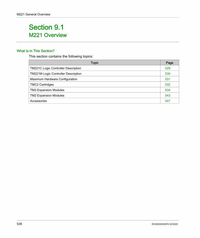
M221 General Overview
M221 Overview
Section 9.1M221 Overview
What Is in This Section?This section contains the following topics:
Topic PageTM221C Logic Controller Description 529TM221M Logic Controller Description 530Maximum Hardware Configuration 531TMC2 Cartridges 532TM3 Expansion Modules 534TM2 Expansion Modules 543Accessories 547
528 EIO0000000976 02/2020

M221 General Overview
TM221C Logic Controller Description
OverviewThe TM221C Logic Controller has various powerful features and can service a wide range of applications.For more information, refer to TM221C Logic Controller Description (see page 28).
EIO0000000976 02/2020 529

M221 General Overview
TM221M Logic Controller Description
OverviewThe TM221M Logic Controller has various powerful features and can service a wide range of applications.For more information, refer to TM221M Logic Controller Description (see page 33).
530 EIO0000000976 02/2020

M221 General Overview
Maximum Hardware Configuration
IntroductionThe M221 Logic Controller is a control system that offers an all-in-one solution with optimized configurations and an expandable architecture.For more information, refer to Maximum Hardware Configuration (see page 131).
EIO0000000976 02/2020 531

M221 General Overview
TMC2 Cartridges
OverviewYou can expand the number of I/Os or communication options of your Modicon TM221C Logic Controller by adding TMC2 cartridges. For more information, refer to the TMC2 Cartridges Hardware Guide.
TMC2 Standard CartridgesThe following table presents the general-purpose TMC2 cartridges with the corresponding channel type, voltage/current range, and terminal type:
TMC2 Application CartridgesThe following table presents the applicative TMC2 cartridges with the corresponding channel type, voltage/current range, and terminal type:
Reference Channels Channel Type VoltageCurrent
Terminal Type
TMC2AI2 2 Analog inputs (voltage or current)
0...10 Vdc0...20 mA or 4...20 mA
3.81 mm (0.15 in.) pitch, non-removable screw terminal block
TMC2TI2 2 Analog temperature inputs
Thermocouple type K, J, R, S, B, E, T, N,C3 wires RTD type Pt100, Pt1000, Ni100, Ni1000
3.81 mm (0.15 in.) pitch, non-removable screw terminal block
TMC2AQ2V 2 Analog voltage outputs
0...10 Vdc 3.81 mm (0.15 in.) pitch, non-removable screw terminal block
TMC2AQ2C 2 Analog current outputs
4...20 mA 3.81 mm (0.15 in.) pitch, non-removable screw terminal block
TMC2SL1 (1) 1 Serial line RS232 or RS485 3.81 mm (0.15 in.) pitch, non-removable screw terminal block
(1) Only one serial line cartridge (TMC2SL1, TMC2CONV01) may be added to a logic controller.
Reference Channels Channel Type VoltageCurrent
Terminal Type
TMC2HOIS01 2 Analog inputs (voltage or current)
0...10 Vdc0...20 mA or 4...20 mA
3.81 mm (0.15 in.) pitch, non-removable screw terminal block
(1) Only one serial line cartridge (TMC2SL1, TMC2CONV01) may be added to a logic controller.
532 EIO0000000976 02/2020

M221 General Overview
TMC2PACK01 2 Analog inputs (voltage or current)
0...10 Vdc0...20 mA or 4...20 mA
3.81 mm (0.15 in.) pitch, non-removable screw terminal block
TMC2CONV01 (1) 1 Serial line RS232 or RS485 3.81 mm (0.15 in.) pitch, non-removable screw terminal block
Reference Channels Channel Type VoltageCurrent
Terminal Type
(1) Only one serial line cartridge (TMC2SL1, TMC2CONV01) may be added to a logic controller.
EIO0000000976 02/2020 533

M221 General Overview
TM3 Expansion Modules
IntroductionThe range of TM3 expansion modules includes: Digital modules, classified as follows: Input modules (see page 534) Output modules (see page 535) Mixed input/output modules (see page 537)
Analog modules, classified as follows: Input modules (see page 537) Output modules (see page 539) Mixed input/output modules (see page 539)
Expert modules (see page 540) Safety modules (see page 541) Transmitter and Receiver modules (see page 542)For more information, refer to the following documents: TM3 Digital I/O Modules Hardware Guide TM3 Analog I/O Modules Hardware Guide TM3 Expert I/O Modules Hardware Guide TM3 Safety Modules Hardware Guide TM3 Transmitter and Receiver Modules Hardware Guide
TM3 Digital Input ModulesThe following table shows the TM3 digital input expansion modules, with corresponding channel type, nominal voltage/current, and terminal type:
Reference Channels Channel Type VoltageCurrent
Terminal Type / Pitch
TM3DI8A 8 Regular inputs 120 Vac7.5 mA
Removable screw terminal block / 5.08 mm
TM3DI8 8 Regular inputs 24 Vdc7 mA
Removable screw terminal block / 5.08 mm
TM3DI8G 8 Regular inputs 24 Vdc7 mA
Removable spring terminal block / 5.08 mm
TM3DI16 16 Regular inputs 24 Vdc7 mA
Removable screw terminal blocks / 3.81 mm
534 EIO0000000976 02/2020

M221 General Overview
TM3 Digital Output ModulesThe following table shows the TM3 digital output expansion modules, with corresponding channel type, nominal voltage/current, and terminal type:
TM3DI16G 16 Regular inputs 24 Vdc7 mA
Removable spring terminal blocks / 3.81 mm
TM3DI16K 16 Regular inputs 24 Vdc5 mA
HE10 (MIL 20) connector
TM3DI32K 32 Regular inputs 24 Vdc5 mA
HE10 (MIL 20) connector
Reference Channels Channel Type VoltageCurrent
Terminal Type / Pitch
Reference Channels Channel Type VoltageCurrent
Terminal Type / Pitch
TM3DQ8R 8 Relay outputs 24 Vdc / 240 Vac7 A maximum per common line / 2 A maximum per output
Removable screw terminal block / 5.08 mm
TM3DQ8RG 8 Relay outputs 24 Vdc / 240 Vac7 A maximum per common line / 2 A maximum per output
Removable spring terminal block / 5.08 mm
TM3DQ8T 8 Regular transistor outputs (source)
24 Vdc4 A maximum per common line/0.5 A maximum per output
Removable screw terminal block / 5.08 mm
TM3DQ8TG 8 Regular transistor outputs (source)
24 Vdc4 A maximum per common line/0.5 A maximum per output
Removable spring terminal block / 5.08 mm
TM3DQ8U 8 Regular transistor outputs (sink)
24 Vdc4 A maximum per common line/0.5 A maximum per output
Removable screw terminal block / 5.08 mm
TM3DQ8UG 8 Regular transistor outputs (sink)
24 Vdc4 A maximum per common line/0.5 A maximum per output
Removable spring terminal block / 5.08 mm
TM3DQ16R 16 Relay outputs 24 Vdc / 240 Vac8 A maximum per common line / 2 A maximum per output
Removable screw terminal blocks / 3.81 mm
EIO0000000976 02/2020 535

M221 General Overview
TM3DQ16RG 16 Relay outputs 24 Vdc / 240 Vac8 A maximum per common line / 2 A maximum per output
Removable spring terminal blocks / 3.81 mm
TM3DQ16T 16 Regular transistor outputs (source)
24 Vdc8 A maximum per common line / 0.5 A maximum per output
Removable screw terminal blocks / 3.81 mm
TM3DQ16TG 16 Regular transistor outputs (source)
24 Vdc8 A maximum per common line / 0.5 A maximum per output
Removable spring terminal blocks / 3.81 mm
TM3DQ16U 16 Regular transistor outputs (sink)
24 Vdc8 A maximum per common line / 0.5 A maximum per output
Removable screw terminal blocks / 3.81 mm
TM3DQ16UG 16 Regular transistor outputs (sink)
24 Vdc8 A maximum per common line / 0.5 A maximum per output
Removable spring terminal blocks / 3.81 mm
TM3DQ16TK 16 Regular transistor outputs (source)
24 Vdc2 A maximum per common line / 0.1 A maximum per output
HE10 (MIL 20) connector
TM3DQ16UK 16 Regular transistor outputs (sink)
24 Vdc2 A maximum per common line / 0.1 A maximum per output
HE10 (MIL 20) connector
TM3DQ32TK 32 Regular transistor outputs (source)
24 Vdc2 A maximum per common line / 0.1 A maximum per output
HE10 (MIL 20) connectors
TM3DQ32UK 32 Regular transistor outputs (sink)
24 Vdc2 A maximum per common line / 0.1 A maximum per output
HE10 (MIL 20) connectors
Reference Channels Channel Type VoltageCurrent
Terminal Type / Pitch
536 EIO0000000976 02/2020

M221 General Overview
TM3 Digital Mixed Input/Output ModulesThis following table shows the TM3 mixed I/O modules, with corresponding channel type, nominal voltage/current, and terminal type:
TM3 Analog Input ModulesThe following table shows the TM3 analog input expansion modules, with corresponding resolution, channel type, nominal voltage/current, and terminal type:
Reference Channels Channel Type VoltageCurrent
Terminal Type / Pitch
TM3DM8R 4 Regular inputs 24 Vdc7 mA
Removable screw terminal block / 5.08 mm4 Relay outputs 24 Vdc / 240 Vac
7 A maximum per common line / 2 A maximum per output
TM3DM8RG 4 Regular inputs 24 Vdc7 mA
Removable spring terminal block /5.08 mm
4 Relay outputs 24 Vdc / 240 Vac7 A maximum per common line / 2 A maximum per output
TM3DM24R 16 Regular inputs 24 Vdc7 mA
Removable screw terminal blocks / 3.81 mm8 Relay outputs 24 Vdc / 240 Vac
7 A maximum per common line / 2 A maximum per output
TM3DM24RG 16 Regular inputs 24 Vdc7 mA
Removable spring terminal blocks / 3.81 mm8 Relay outputs 24 Vdc / 240 Vac
7 A maximum per common line / 2 A maximum per output
Reference Resolution Channels Channel Type
Mode Terminal Type / Pitch
TM3AI2H 16 bit, or 15 bit + sign
2 inputs 0...10 Vdc-10…+10 Vdc0...20 mA4...20 mA
Removable screw terminal block / 5.08 mm
EIO0000000976 02/2020 537

M221 General Overview
TM3AI2HG 16 bit, or 15 bit + sign
2 inputs 0...10 Vdc-10…+10 Vdc0...20 mA4...20 mA
Removable spring terminal block / 5.08 mm
TM3AI4 12 bit, or 11 bit + sign
4 inputs 0...10 Vdc-10…+10 Vdc0...20 mA4...20 mA
Removable screw terminal block / 3.81 mm
TM3AI4G 12 bit, or 11 bit + sign
4 inputs 0...10 Vdc-10…+10 Vdc0...20 mA4...20 mA
Removable spring terminal blocks / 3.81 mm
TM3AI8 12 bit, or 11 bit + sign
8 inputs 0...10 Vdc-10…+10 Vdc0...20 mA4...20 mA0...20 mA extended4...20 mA extended
Removable screw terminal block / 3.81 mm
TM3AI8G 12 bit, or 11 bit + sign
8 inputs 0...10 Vdc-10…+10 Vdc0...20 mA4...20 mA0...20 mA extended4...20 mA extended
Removable spring terminal blocks / 3.81 mm
TM3TI4 16 bit, or 15 bit + sign
4 inputs 0...10 Vdc-10…+10 Vdc0...20 mA4...20 mAThermocouplePT100/1000NI100/1000
Removable screw terminal block / 3.81 mm
TM3TI4G 16 bit, or 15 bit + sign
4 inputs 0...10 Vdc-10…+10 Vdc0...20 mA4...20 mAThermocouplePT100/1000NI100/1000
Removable spring terminal blocks / 3.81 mm
TM3TI4D 16 bit, or 15 bit + sign
4 inputs Thermocouple Removable screw terminal block / 3.81 mm
TM3TI4DG 16 bit, or 15 bit + sign
4 inputs Thermocouple Removable spring terminal blocks / 3.81 mm
Reference Resolution Channels Channel Type
Mode Terminal Type / Pitch
538 EIO0000000976 02/2020

M221 General Overview
TM3 Analog Output ModulesThe following table shows the TM3 analog output modules, with corresponding resolution, channel type, nominal voltage/current, and terminal type:
TM3 Analog Mixed Input/Output ModulesThis following table shows the TM3 analog mixed I/O modules, with corresponding resolution, channel type, nominal voltage/current, and terminal type:
TM3TI8T 16 bit, or 15 bit + sign
8 inputs ThermocoupleNTC/PTCOhmmeter
Removable screw terminal block / 3.81 mm
TM3TI8TG 16 bit, or 15 bit + sign
8 inputs ThermocoupleNTC/PTCOhmmeter
Removable spring terminal blocks / 3.81 mm
Reference Resolution Channels Channel Type
Mode Terminal Type / Pitch
Reference Resolution Channels Channel Type
Mode Terminal Type / Pitch
TM3AQ2 12 bit, or 11 bit + sign
2 outputs 0...10 Vdc-10…+10 Vdc0...20 mA4...20 mA
Removable screw terminal block / 5.08 mm
TM3AQ2G 12 bit, or 11 bit + sign
2 outputs 0...10 Vdc-10…+10 Vdc0...20 mA4...20 mA
Removable spring terminal block / 5.08 mm
TM3AQ4 12 bit, or 11 bit + sign
4 outputs 0...10 Vdc-10…+10 Vdc0...20 mA4...20 mA
Removable screw terminal block / 5.08 mm
TM3AQ4G 12 bit, or 11 bit + sign
4 outputs 0...10 Vdc-10…+10 Vdc0...20 mA4...20 mA
Removable spring terminal block / 5.08 mm
Reference Resolution Channels Channel Type
Mode Terminal Type / Pitch
TM3AM6 12 bit, or 11 bit + sign
4 inputs 0...10 Vdc-10...+10 Vdc0...20 mA4...20 mA
Removable screw terminal block / 3.81 mm
2 outputs
EIO0000000976 02/2020 539

M221 General Overview
TM3 Expert ModuleThe following table shows the TM3 expert expansion module, with corresponding terminal type:
TM3AM6G 12 bit, or 11 bit + sign
4 inputs 0...10 Vdc-10...+10 Vdc0...20 mA4...20 mA
Removable spring terminal block / 3.81 mm
2 outputs
TM3TM3 16 bit, or 15 bit + sign
2 inputs 0...10 Vdc-10...+10 Vdc0...20 mA4...20 mAThermocouplePT100/1000NI100/1000
Removable screw terminal block / 5.08 mm
12 bit, or 11 bit + sign
1 outputs 0...10 Vdc-10...+10 Vdc0...20 mA4...20 mA
TM3TM3G 16 bit, or 15 bit + sign
2 inputs 0...10 Vdc-10...+10 Vdc0...20 mA4...20 mAThermocouplePT100/1000NI100/1000
Removable spring terminal block / 5.08 mm
12 bit, or 11 bit + sign
1 outputs 0...10 Vdc-10...+10 Vdc0...20 mA4...20 mA
Reference Resolution Channels Channel Type
Mode Terminal Type / Pitch
Reference Description Terminal Type / PitchTM3XTYS4 TeSys module 4 front connectors RJ-45
1 power supply connector / 5.08 mm
540 EIO0000000976 02/2020

M221 General Overview
TM3 Safety ModulesThis table contains the TM3 safety modules, with the corresponding channel type, nominal voltage/current, and terminal type:
Reference FunctionCategory
Channels Channel type VoltageCurrent
Terminal type
TM3SAC5R 1 function, up to category 3
1 or 2 (1) Safety input 24 Vdc100 mA maximum
3.81 mm (0.15 in.) and 5.08 mm (0.20 in.), removable screw terminal block
Start (2) Input
3 in parallel Relay outputsNormally open
24 Vdc / 230 Vac6 A maximum per output
TM3SAC5RG 1 function, up to category 3
1 or 2 (1) Safety input 24 Vdc100 mA maximum
3.81 mm (0.15 in.) and 5.08 mm (0.20 in.), removable spring terminal block
Start (2) Input
3 in parallel Relay outputsNormally open
24 Vdc / 230 Vac6 A maximum per output
TM3SAF5R 1 function, up to category 4
2 (1) Safety inputs 24 Vdc100 mA maximum
3.81 mm (0.15 in.) and 5.08 mm (0.20 in.), removable screw terminal block
Start Input3 in parallel Relay outputs
Normally open24 Vdc / 230 Vac6 A maximum per output
TM3SAF5RG 1 function, up to category 4
2 (1) Safety inputs 24 Vdc100 mA maximum
3.81 mm (0.15 in.) and 5.08 mm (0.20 in.), removable spring terminal block
Start Input3 in parallel Relay outputs
Normally open24 Vdc / 230 Vac6 A maximum per output
TM3SAFL5R 2 functions, up to category 3
2 (1) Safety inputs 24 Vdc100 mA maximum
3.81 mm (0.15 in.) and 5.08 mm (0.20 in.), removable screw terminal block
Start Input3 in parallel Relay outputs
Normally open24 Vdc / 230 Vac6 A maximum per output
TM3SAFL5RG 2 functions, up to category 3
2 (1) Safety inputs 24 Vdc100 mA maximum
3.81 mm (0.15 in.) and 5.08 mm (0.20 in.), removable spring terminal block
Start Input3 in parallel Relay outputs
Normally open24 Vdc / 230 Vac6 A maximum per output
TM3SAK6R 3 functions, up to category 4
1 or 2 (1) Safety inputs 24 Vdc100 mA maximum
3.81 mm (0.15 in.) and 5.08 mm (0.20 in.), removable screw terminal block
Start Input3 in parallel Relay outputs
Normally open24 Vdc / 230 Vac6 A maximum per output
(1) Depending on external wiring(2) Non-monitored start
EIO0000000976 02/2020 541

M221 General Overview
TM3 Transmitter and Receiver ModulesThe following table shows the TM3 transmitter and receiver expansion modules:
TM3SAK6RG 3 functions, up to category 4
1 or 2 (1) Safety inputs 24 Vdc100 mA maximum
3.81 mm (0.15 in.) and 5.08 mm (0.20 in.), removable spring terminal block
Start Input3 in parallel Relay outputs
Normally open24 Vdc / 230 Vac6 A maximum per output
Reference FunctionCategory
Channels Channel type VoltageCurrent
Terminal type
(1) Depending on external wiring(2) Non-monitored start
Reference Description Terminal Type / PitchTM3XTRA1 Data transmitter module for remote I/O 1 front connector RJ-45
1 screw for functional ground connection
TM3XREC1 Data receiver module for remote I/O 1 front connector RJ-45Power supply connector / 5.08 mm
542 EIO0000000976 02/2020

M221 General Overview
TM2 Expansion Modules
OverviewYou can expand the number of I/Os of your M221 Logic Controller by adding TM2 I/O expansion modules. The following types of electronic modules are supported: TM2 digital I/O expansion modules TM2 analog I/O expansion modulesFor more information, refer to the following documents: TM2 Digital I/O Expansion Modules Hardware Guide TM2 Analog I/O Expansion Modules Hardware GuideNOTE: TM2 modules can only be used in the local configuration, and only if there is no TM3 transmitter and receiver modules present in the configuration.NOTE: It is prohibited to mount a TM2 module before any TM3 module. The TM2 modules must be mounted and configured at the end of the local configuration.
TM2 Digital Input Expansion ModulesThe following table shows the compatible TM2 digital input expansion modules with the corresponding channel type, nominal voltage/current, and terminal type:
TM2 Digital Output Expansion ModulesThe following table shows the compatible TM2 digital output expansion modules with the corresponding channel type, nominal voltage/current, and terminal type:
Reference Channels Channel Type VoltageCurrent
Terminal Type
TM2DAI8DT 8 Regular inputs 120 Vac7.5 mA
Removable screw terminal block
TM2DDI8DT 8 Regular inputs 24 Vdc7 mA
Removable screw terminal block
TM2DDI16DT 16 Regular inputs 24 Vdc7 mA
Removable screw terminal block
TM2DDI16DK 16 Regular inputs 24 Vdc5 mA
HE10 (MIL 20) connector
TM2DDI32DK 32 Regular inputs 24 Vdc5 mA
HE10 (MIL 20) connector
Reference Channels Channel type VoltageCurrent
Terminal type
TM2DRA8RT 8 Relay outputs 30 Vdc / 240 Vac2 A max
Removable screw terminal block
EIO0000000976 02/2020 543

M221 General Overview
TM2 Digital Mixed Input/Output Expansion ModulesThe following table shows the compatible TM2 digital mixed I/O expansion modules with the corresponding channel type, nominal voltage/current, and terminal type:
TM2DRA16RT 16 Relay outputs 30 Vdc / 240 Vac2 A max
Removable screw terminal block
TM2DDO8UT 8 Regular transistor outputs (sink)
24 Vdc0.3 A max per output
Removable screw terminal block
TM2DDO8TT 8 Regular transistor outputs (source)
24 Vdc0.5 A max per output
Removable screw terminal block
TM2DDO16UK 16 Regular transistor outputs (sink)
24 Vdc0.1 A max per output
HE10 (MIL 20) connector
TM2DDO16TK 16 Regular transistor outputs (source)
24 Vdc0.4 A max per output
HE10 (MIL 20) connector
TM2DDO32UK 32 Regular transistor outputs (sink)
24 Vdc0.1 A max per output
HE10 (MIL 20) connector
TM2DDO32TK 32 Regular transistor outputs (source)
24 Vdc0.4 A max per output
HE10 (MIL 20) connector
Reference Channels Channel type VoltageCurrent
Terminal type
Reference Channels Channel type VoltageCurrent
Terminal type
TM2DMM8DRT 4 Regular inputs 24 Vdc7 mA
Removable screw terminal block
4 Relay outputs 24 Vdc / 240 Vac7 A maximum per common line / 2 A maximum per output
TM2DMM24DRF 16 Regular inputs 24 Vdc7 mA
Non-removable spring terminal block8 Relay outputs 24 Vdc / 240 Vac
7 A maximum per common line / 2 A maximum per output
544 EIO0000000976 02/2020

M221 General Overview
TM2 Analog Input Expansion ModulesThe following table shows the compatible TM2 analog input expansion modules with the corresponding channel type, nominal voltage/current, and terminal type:
TM2 Analog Output Expansion ModulesThe following table shows the compatible TM2 analog output expansion modules with the corresponding channel type, nominal voltage/current, and terminal type:
TM2 Analog Mixed Input/Output Expansion ModulesThe following table shows the compatible TM2 analog mixed I/O expansion modules with the corresponding channel type, nominal voltage/current, and terminal type:
Reference Channels Channel type VoltageCurrent
Terminal Type
TM2AMI2HT 2 High-level inputs 0...10 Vdc4...20 mA
Removable screw terminal block
TM2AMI2LT 2 Low-level inputs Thermocouple type J,K,T
Removable screw terminal block
TM2AMI4LT 4 Analog inputs 0...10 Vdc0...20 mAPT100/1000Ni100/1000
Removable screw terminal block
TM2AMI8HT 8 Analog inputs 0...20 mA0...10 Vdc
Removable screw terminal block
TM2ARI8HT 8 Analog inputs NTC / PTC Removable screw terminal block
TM2ARI8LRJ 8 Analog inputs PT100/1000 RJ11 connectorTM2ARI8LT 8 Analog inputs PT100/1000 Removable screw
terminal block
Reference Channels Channel type VoltageCurrent
Terminal Type
TM2AMO1HT 1 Analog outputs 0...10 Vdc4...20 mA
Removable screw terminal block
TM2AVO2HT 2 Analog outputs +/- 10 Vdc Removable screw terminal block
Reference Channels Channel type VoltageCurrent
Terminal Type
TM2AMM3HT 2 Analog inputs 0...10 Vdc 4...20 mA Removable screw terminal block1 Analog outputs 0...10 Vdc 4...20 mA
EIO0000000976 02/2020 545

M221 General Overview
TM2AMM6HT 4 Analog inputs 0...10 Vdc 4...20 mA Removable screw terminal block2 Analog outputs 0...10 Vdc 4...20 mA
TM2ALM3LT 2 Low-level inputs Thermo J,K,T, PT100
Removable screw terminal block
1 Analog outputs 0...10 Vdc 4...20 mA
Reference Channels Channel type VoltageCurrent
Terminal Type
546 EIO0000000976 02/2020

M221 General Overview
Accessories
OverviewThis section describes the accessories, cables, and Telefast.
Accessories
Reference Description Use QuantityTMASD1 SD Card (see page 571) Use to update the controller firmware, store data (data
logging), initialize a controller with a new application or clone a controller.
1
TMAT2MSET Set of 8 removable screw terminal blocks: 4 x Removable screw
terminal blocks (pitch 3.81 mm) with 11 terminals for inputs/outputs
4 x Removable screw terminal blocks (pitch 3.81 mm) with 10 terminals for inputs/outputs
Connects M221 Logic Controller embedded I/Os. 1
TMAT2MSETG Set of 8 removable spring terminal blocks: 4 x Removable spring
terminal blocks (pitch 3.81 mm) with 11 terminals for inputs/outputs
4 x Removable spring terminal blocks (pitch 3.81 mm) with 10 terminals for inputs/outputs
Connects M221 Logic Controller embedded I/Os. 1
TMAT2PSET Set of 5 removable screw terminal block
Connects 24 Vdc power supply. 1
AB1AB8P35 End brackets Help secure the logic controller or receiver module and their expansion modules on a top hat section rail (DIN rail).
1
TM2XMTGB Grounding Bar Connects the cable shield and the module to the functional ground.
1
TM200RSRCEMC Shielding take-up clip Mounts and connects the ground to the cable shielding.
25 pack
EIO0000000976 02/2020 547

M221 General Overview
Cables
TMAM2 Mounting Kit Mounts the controller and I/O modules directly to a flat, vertical panel.
1Reference Description Use Quantity
Reference Description Details LengthBMXXCAUSBH018 Terminal port/USB
port cordsetFrom the USB mini-B port on the TM221C Logic Controller to USB port on the PC terminal.
NOTE: Grounded and shielded, this USB cable is suitable for long duration connections.
1.8 m(5.9 ft)
BMXXCAUSBH045 Terminal port/USB port cordset
From the USB mini-B port on the TM221M Logic Controller to USB port on the PC terminal.
NOTE: Grounded and shielded, this USB cable is suitable for long duration connections.
4.5 m(14.8 ft)
TMACBL1 Analog cables Cable equipped with a connector 1 m(3.28 ft)
TCSMCN3M4F3C2 RS-232 serial link cordset1 RJ45 connector and 1 SUB-D 9 connector
For DTE terminal (printer) 3 m(9.84 ft)
TCSMCN3M4M3S2 RS-232 serial link cordset1 RJ45 connector and 1 SUB-D 9 connector
For DCE terminal (modem, converter) 3 m(9.84 ft)
TWDFCW30K Digital I/O cables with free wires for 20-pin Modular controller
Cable equipped at a one end with an HE10 connector. (AWG 22 / 0.34 mm2)
3 m(9.84 ft)
TWDFCW50K Cable equipped at a one end with an HE10 connector. (AWG 22 / 0.34 mm2)
5 m(16.4 ft)
548 EIO0000000976 02/2020

M221 General Overview
TWDFCW••K Cable DescriptionThe following table provides specifications for the TWDFCW30K/50K with free wires for 20-pin connectors (HE10 or MIL20):
Cable illustration Pin Connector
Wire Color
1 White2 Brown3 Green4 Yellow5 Grey6 Pink7 Blue8 Red9 Black10 Violet11 Grey and pink12 Red and blue13 White and green14 Brown and green15 White and yellow16 Yellow and brown17 White and grey18 Grey and brown19 White and pink20 Pink and brown
EIO0000000976 02/2020 549

M221 General Overview
Telefast Pre-Wiring Sub-basesThe following illustration shows the Telefast system:
1 TM221M32TK / TM221ME32TK2 Cable equipped with a 20-way HE 10 connector at each end.)3 16 channel sub-base for input extension modules.4 16 channel sub-base for output extension modules.5 16 channel sub-base for output extension modules.
550 EIO0000000976 02/2020

M221 General Overview
Refer to TM221M Logic Controller Instruction Sheet.
EIO0000000976 02/2020 551

M221 General Overview
M221 Features
Section 9.2M221 Features
OverviewThis chapter describes the Modicon M221 Logic Controller features.
What Is in This Section?This section contains the following topics:
Topic PageReal Time Clock (RTC) 553Input Management 560Output Management 564Run/Stop 568SD Card 571
552 EIO0000000976 02/2020

M221 General Overview
Real Time Clock (RTC)
OverviewThe M221 Logic Controller includes an RTC to provide system date and time information, and to support related functions requiring a real-time clock. To continue keeping time when power is off, a non-rechargeable battery is required (see reference below). A battery LED on the front panel of the controller indicates if the battery is depleted or absent.This table shows how RTC drift is managed:
BatteryThe controller has one backup battery.In the event of a power interruption, the backup battery maintains user data and the RTC for the controller.This table shows the characteristics of the battery:
Installing and Replacing the BatteryWhile lithium batteries are preferred due to their slow discharge and long life, they can present hazards to personnel, equipment and the environment and must be handled properly.
RTC Characteristics DescriptionRTC drift Less than 30 seconds per month at 25 °C (77 °F)
Characteristics DescriptionUse In the event of a transient power outage, the battery powers the RTC and user
data.Backup life At least 1 year at 25 °C maximum (77 °F). At higher temperatures, the time is
reduced.Battery monitoring YesReplaceable YesBattery life 4 years at 25 °C maximum (77 °F). At higher temperatures, the time is
reduced.Controller battery type Lithium carbon monofluoride, type Panasonic BR2032
EIO0000000976 02/2020 553

M221 General Overview
To install or replace the battery, follow these steps:
DANGEREXPLOSION, FIRE, OR CHEMICAL BURNS Replace with identical battery type. Follow all the instructions of the battery manufacturer. Remove all replaceable batteries before discarding unit. Recycle or properly dispose of used batteries. Protect battery from any potential short-circuit. Do not recharge, disassemble, heat above 100 °C (212 °F), or incinerate. Use your hands or insulated tools to remove or replace the battery. Maintain proper polarity when inserting and connecting a new battery.Failure to follow these instructions will result in death or serious injury.
Step Action1 Remove power from your controller.
554 EIO0000000976 02/2020

M221 General Overview
2 Use an insulated screw-driver to pull out the battery holder from the TM221C Logic Controller.
Use an insulated screw-driver to pull out the battery holder from the TM221M Logic Controller.
Step Action
EIO0000000976 02/2020 555

M221 General Overview
3 Slide out the battery holder of the TM221C Logic Controller.
Slide out the battery holder of the TM221M Logic Controller.
Step Action
556 EIO0000000976 02/2020

M221 General Overview
4 Remove the battery from the battery holder.
5 Insert the new battery into the battery holder in accordance with the polarity markings on the battery.
6 Replace the battery holder on the controller and verify that the latch clicks into place.
Step Action
EIO0000000976 02/2020 557

M221 General Overview
NOTE: Replacement of the battery in the controllers other than with the type specified in this documentation may present a risk of fire or explosion.
7 Slide in the battery holder of the TM221C Logic Controller.
Slide in the battery holder of the TM221M Logic Controller.
8 Power up your M221 Logic Controller.9 Set the internal clock. For further details on the internal clock, refer to EcoStruxure Machine Expert
- Basic Operating Guide.
Step Action
558 EIO0000000976 02/2020

M221 General Overview
WARNINGIMPROPER BATTERY CAN PROVOKE FIRE OR EXPLOSIONReplace battery only with identical type: Panasonic Type BR2032.Failure to follow these instructions can result in death, serious injury, or equipment damage.
EIO0000000976 02/2020 559

M221 General Overview
Input Management
OverviewThe M221 Logic Controller features digital inputs, including 4 fast inputs.The following functions are configurable: Filters (depends on the function associated with the input). I0...I15 inputs can be used for the Run/Stop function. Four fast inputs can be either latched or used for events (rising edge, falling edge, or both) and
thus be linked to an external task.NOTE: All inputs can be used as regular inputs.
Integrator Filter PrincipleThe filter is designed to reduce the bouncing effect at the inputs. Setting a filter value helps the controller to ignore sudden changes of input levels caused by induction of electromagnetic interference.The following timing diagram illustrates the filter effects:
Bounce Filter AvailabilityThe bounce filter can be used on a fast input when: Using a latch or event HSC is enabled
560 EIO0000000976 02/2020

M221 General Overview
LatchingLatching is a function that can be assigned to the M221 Logic Controller fast inputs. This function is used to memorize (or latch) any pulse with a duration that is less than the M221 Logic Controller scan time. When a pulse is shorter than one scan, the controller latches the pulse, which is then updated in the next scan. This latching mechanism only recognizes rising edges. Falling edges cannot be latched. Assigning inputs to be latched is done in the Configuration tab in EcoStruxure Machine Expert - Basic.The following timing diagram illustrates the latching effects:
EventAn input configured for Event can be associated with an External Task.
Run/StopThe Run/Stop function is used to start or stop an application program using an input. In addition to the embedded Run/Stop switch, you can configure one (and only one) input as an additional Run/Stop command.For more information, refer to the Run/Stop (see page 568).
WARNINGUNINTENDED MACHINE OR PROCESS START-UP Verify the state of security of your machine or process environment before applying power to
the Run/Stop input. Use the Run/Stop input to help prevent the unintentional start-up from a remote location.Failure to follow these instructions can result in death, serious injury, or equipment damage.
EIO0000000976 02/2020 561

M221 General Overview
Input Management Functions AvailabilityEmbedded digital inputs can be assigned to functions (Run/Stop, Latch, Event, Fast Counter, HSC, PTO). Inputs not assigned to functions are used as regular inputs. The following table presents the possible assignments of the embedded M221 Logic Controller digital inputs:
FunctionSimple Input Function Advanced Input Function
Run/Stop Latch Event Fast Counter
HSC PTO(3)
Fast Input %I0.0 X – – – %HSC0 –%I0.1 X – – – %HSC0 or %HSC2(1) –
Regular Input
%I0.2 X X X %FC0 Preset for %HSC0 Ref or probe for %PTO0 to %PTO3%I0.3 X X X %FC1 Catch for %HSC0
%I0.4 X X X %FC2 Catch for %HSC1%I0.5 X X X %FC3 Preset for %HSC1
Fast Input %I0.6 X – – – %HSC1 –%I0.7 X – – – %HSC1 or %HSC3(2) –
X Yes– No(1) %HSC2 is available when %HSC0 is configured as Single Phase or Not Configured.(2) %HSC3 is available when %HSC1 is configured as Single Phase or Not Configured.(3) PTO function is available on controller references that contain transistor outputs.
562 EIO0000000976 02/2020

M221 General Overview
Regular Input
(depending on the
controller reference)
%I0.8 X – – – – Ref or probe for %PTO0 to %PTO3 on
TM221C40U and TM221CE40U
controllers
%I0.9 X – – – –
%I0.10 X – – – – –%I0.11 X – – – – –%I0.12 X – – – – –%I0.13 X – – – – –%I0.14 X – – – – –%I0.15 X – – – – –%I0.16 X – – – – –%I0.17 X – – – – –%I0.18 X – – – – –%I0.19 X – – – – –%I0.20 X – – – – –%I0.21 X – – – – –%I0.22 X – – – – –%I0.23 X – – – – –
FunctionSimple Input Function Advanced Input Function
Run/Stop Latch Event Fast Counter
HSC PTO(3)
X Yes– No(1) %HSC2 is available when %HSC0 is configured as Single Phase or Not Configured.(2) %HSC3 is available when %HSC1 is configured as Single Phase or Not Configured.(3) PTO function is available on controller references that contain transistor outputs.
EIO0000000976 02/2020 563

M221 General Overview
Output Management
IntroductionThe M221 Logic Controller features both regular and fast transistor outputs (PLS/PWM/PTO/FREQGEN).The following output functions are configurable on the transistor outputs: Alarm output HSC (reflex features on HSC threshold) PLS PTO PWM FREQGENNOTE: All outputs can be used as regular outputs.
Output Management AvailabilityThe information below refers to regular and fast transistor outputs on the M221 Logic Controller:
Function Alarm Output
HSC PLS / PWM / PTO / FREQGEN
Fast Output(1)
%Q0.0 X – • %PLS0• %PWM0• %PTO0
• %FREQGEN0%Q0.1 X – • %PLS1
• %PWM1• %PTO(2)
• %FREQGEN1(1) Fast output functions are only available on controller references that contain transistor outputs.(2) %PTO0 direction in CW/CCW output mode, or %PTO1 (not available when %PTO0 is configured in CW/CCW output
mode), or %PTOx direction in other cases.(3) %Q0.2 and %Q0.3 are fast outputs on TM221C40U and TM221CE40U controllers(4) %PTO2 on TM221C40U and TM221CE40U controllers, or %PTOx direction in other cases.(5) %PTO2 direction in CW/CCW output mode on TM221C40U and TM221CE40U controllers, or %PTO3 (not available
when %PTO2 is configured in CW/CCW output mode) on TM221C40U and TM221CE40U controllers, or %PTOx direction in other cases.
564 EIO0000000976 02/2020

M221 General Overview
Fallback Modes (Behavior for Outputs in Stop)When the controller enters the STOPPED or one of the exception states for any reason, the local (embedded and expansion) outputs are set to Default Value defined in the application.In case of PTO outputs, the fallback values are forced to 0 logic (0 Vdc) and these values cannot be modified.
Short-circuit or Over-current on Source Transistor OutputsOutputs are clustered in packs of 4 outputs maximum (less when the total number of outputs of the controller is not a multiple of 4): Q0...Q3 Q4...Q7
Regular Output(3)
(depending on the
controller reference)
%Q0.2 X Reflex output 0 for %HSC0 or %HSC2 • %PTO(4)
• %FREQGEN2%Q0.3 X Reflex output 1 for %HSC0 or %HSC2 • %PTO(5)
• %FREQGEN3%Q0.4 X Reflex output 0 for %HSC1 or %HSC3 %PTOx direction%Q0.5 X Reflex output 1 for %HSC1 or %HSC3 %PTOx direction%Q0.6 X – %PTOx direction%Q0.7 X – %PTOx direction%Q0.8 – – %PTOx direction%Q0.9 – – %PTOx direction%Q0.10 – – %PTOx direction%Q0.11 – – %PTOx direction%Q0.12 – – %PTOx direction%Q0.13 – – %PTOx direction%Q0.14 – – %PTOx direction%Q0.15 – – %PTOx direction
Function Alarm Output
HSC PLS / PWM / PTO / FREQGEN
(1) Fast output functions are only available on controller references that contain transistor outputs.(2) %PTO0 direction in CW/CCW output mode, or %PTO1 (not available when %PTO0 is configured in CW/CCW output
mode), or %PTOx direction in other cases.(3) %Q0.2 and %Q0.3 are fast outputs on TM221C40U and TM221CE40U controllers(4) %PTO2 on TM221C40U and TM221CE40U controllers, or %PTOx direction in other cases.(5) %PTO2 direction in CW/CCW output mode on TM221C40U and TM221CE40U controllers, or %PTO3 (not available
when %PTO2 is configured in CW/CCW output mode) on TM221C40U and TM221CE40U controllers, or %PTOx direction in other cases.
EIO0000000976 02/2020 565

M221 General Overview
Q8...Q11 Q12...Q15When a short-circuit or overload is detected and the system bit %S49 is set to 1, the cluster of 4 outputs is set to 0. An automatic rearming is done periodically (about 1 s). Only the short-circuit between an output set to 1 and 0 V is detected. The short-circuit between an output set to 0 and 24 V is not detected.NOTE: By default, %S49 is set to 0.
The following table describes the actions taken on short-circuits or overload of transistor outputs from Q0 to Q3:
In the case of a short-circuit or current overload, the common group of outputs automatically enters into thermal protection mode (all outputs in the group are set to 0), and are then periodically rearmed (each second) to test the connection state. However, you must be aware of the effect of this rearming on the machine or process being controlled.
NOTE: The automatic rearming feature can be disabled with the system bit %S49. Refer to the Programming Guide of your controller for more information.
Short-circuit or Over-Current on Sink Transistor OutputsSink transistor outputs are not internally protected against overloads or short-circuits.The following table describes the actions taken on overloads or short-circuits on sink transistor outputs:
For more information, refer to Sink Transistor Outputs Wiring Diagrams (see page 735).
If... then...If you have short-circuit at 0 V on transistor outputs
Transistor outputs automatically go into over-current protection or thermal protection mode.For more information, refer to transistor output wiring diagrams.
WARNINGUNINTENDED MACHINE START-UPInhibit the automatic rearming of outputs if this feature is an undesirable behavior for your machine or process.Failure to follow these instructions can result in death, serious injury, or equipment damage.
If... then ...If you have short-circuit or overload at 0 V, or 24 V on sink transistor outputs
no action is taken and no error is detectable.
566 EIO0000000976 02/2020

M221 General Overview
Short-circuit or Over-Current on Relay OutputsRelay outputs are not internally protected against overloads or short-circuits.The following table describes the actions taken on overloads or short-circuits on relay outputs:
Relay outputs are electromechanical switches capable of carrying significant levels of current and voltage. All electromechanical devices have a limited operational life and must be installed so as to minimize the potential for unintended consequences.
If... then...If you have short-circuit or overload at 0 V or 24 V on relay outputs
No action is taken and no error is detectable.For more information, refer to relay output wiring diagrams.
WARNINGINOPERABLE OUTPUTSUse appropriate, external safety interlocks on outputs where personnel and/or equipment hazards exist.Failure to follow these instructions can result in death, serious injury, or equipment damage.
EIO0000000976 02/2020 567

M221 General Overview
Run/Stop
Run/StopThe M221 Logic Controller can be operated externally by the following: a hardware Run/Stop switch a Run/Stop (see page 561) operation by a dedicated digital input, defined in the software
configuration. For more information, refer to Configuring Digital Inputs (see page 97). an EcoStruxure Machine Expert - Basic software command. a Remote Graphic Display (see page 921).The M221 Logic Controller has a Run/Stop hardware switch, which puts the controller in a RUN or STOP state.The following figure shows the location of the Run/Stop switch on the TM221C Logic Controller:
568 EIO0000000976 02/2020

M221 General Overview
The following figure shows the location of the Run/Stop switch on the TM221M Logic Controller:
The interaction of the different operators on the controller state behavior is summarized in the table below:
Embedded Run/Stop hardware switchSwitch on Stop Stop to Run transition Switch on Run
Software configurable Run/Stop digital input
None STOPIgnores external Run/Stop commands2.
Commands a transition to RUN state1.
Allows external Run/Stop commands2.
State 0 STOPIgnores external Run/Stop commands2.
STOPIgnores external Run/Stop commands2.
STOPIgnores external Run/Stop commands2.
Rising edge
STOPIgnores external Run/Stop commands2.
Commands a transition to RUN state1.
Commands a transition to RUN state1.
State 1 STOPIgnores external Run/Stop commands2.
Commands a transition to RUN state1.
Allows external Run/Stop commands2.
1 For more information, refer to the Controller States and Behaviors (see page 62).2 External Run/Stop commands sent by the EcoStruxure Machine Expert - Basic online button or a Remote Graphic Display.
EIO0000000976 02/2020 569

M221 General Overview
WARNINGUNINTENDED MACHINE OR PROCESS START-UP Verify the state of security of your machine or process environment before applying power to
the Run/Stop input or engaging the Run/Stop switch. Use the Run/Stop input to help prevent the unintentional start-up from a remote location, or
from accidentally engaging the Run/Stop switch.Failure to follow these instructions can result in death, serious injury, or equipment damage.
570 EIO0000000976 02/2020

M221 General Overview
SD Card
OverviewWhen handling the SD card, follow the instructions below to help prevent internal data on the SD card from being corrupted or lost or a SD card malfunction from occurring:
The M221 Logic Controller does not recognize NTFS formatted SD cards. Format the SD card on your computer using FAT or FAT32.When using the M221 Logic Controller and a SD card, observe the following to avoid losing valuable data: Accidental data loss can occur at any time. Once data is lost it cannot be recovered. If you forcibly extract the SD card, data on the SD card may become corrupted. Removing an SD card that is being accessed could damage the SD card, or corrupt its data. If the SD card is not positioned correctly when inserted into the controller, the data on the card
and the controller could become damaged.
NOTICELOSS OF APPLICATION DATA Do not store the SD card where there is static electricity or probable electromagnetic fields. Do not store the SD card in direct sunlight, near a heater, or other locations where high
temperatures can occur. Do not bend the SD card. Do not drop or strike the SD card against another object. Keep the SD card dry. Do not touch the SD card connectors. Do not disassemble or modify the SD card. Use only SD cards formatted using FAT or FAT32.Failure to follow these instructions can result in equipment damage.
NOTICELOSS OF APPLICATION DATA Backup SD card data regularly. Do not remove power or reset the controller, and do not insert or remove the SD card while it
is being accessed.Failure to follow these instructions can result in equipment damage.
EIO0000000976 02/2020 571

M221 General Overview
The following figure shows the SD card slot of the TM221C Logic Controller:
The following figure shows the SD card slot of the TM221M Logic Controller:
572 EIO0000000976 02/2020

M221 General Overview
It is possible to set the Write-Control Tab to prevent write operations to the SD card. Push the tab up, as shown in the example on the right-hand side, to release the lock and enable writing to the SD card. Before using an SD card, read the manufacturer's instructions.
EIO0000000976 02/2020 573

M221 General Overview
Step Action1 Insert the SD card into the SD card slot of the TM221C Logic Controller:
Insert the SD card into the SD card slot of the TM221M Logic Controller:
574 EIO0000000976 02/2020

M221 General Overview
SD Card Slot Characteristics
2 Push until you hear it “click” (TM221C Logic Controller):
Push until you hear it “click” (TM221M Logic Controller):
Step Action
Topic Characteristics DescriptionSupported type Standard Capacity SD (SDSC)
High Capacity SDHCGlobal memory Size 32 GB max.Memory organization Application backup size 64 MB
Data storage size 1.93 GBRobustness Write/erase cycles (typical) 100,000
Temperature operating range –40...+85 °C (–40...+185 °F)File retention time 10 years
EIO0000000976 02/2020 575

M221 General Overview
TMASD1 Characteristics
NOTE: The TMASD1 has been rigorously tested in association with the logic controller. For other commercially available cards, consult your local sales representative.NOTE: The SD card can be used directly on your PC.
Status LEDThe following figure shows the status LEDs of the TM221C Logic Controller:
The following figure shows the status LEDs of the TM221M Logic Controller:
Characteristics DescriptionCard removal durability Minimum 1000 timesFile retention time 10 years @ 25 °C (77 °F)Flash type SLC NANDMemory size 256 MBAmbient operation temperature –10 … +85°C (14...185 °F)Storage temperature –25 … +85°C (–13...185 °F)Relative humidity 95% max. non-condensingWrite/Erase cycles 3,000,000 (approximately)
576 EIO0000000976 02/2020

M221 General Overview
The following table describes the SD card status LED:
Label Description LEDColor Status Description
SD SD card Green On Indicates that the SD card is being accessed.
Off Indicates no access.Flashing Indicates that an error was detected
during the SD card operation.
EIO0000000976 02/2020 577

M221 General Overview
M221 Installation
Section 9.3M221 Installation
OverviewThis chapter provides installation safety guidelines, device dimensions, mounting instructions, and environmental specifications.
What Is in This Section?This section contains the following topics:
Topic PageEnvironmental Characteristics 579Certifications and Standards 582Installation and Maintenance Requirements 583TM221M Logic Controller Mounting Positions and Clearances 586Top Hat Section Rail (DIN rail) 589TM221C Logic Controller Mounting Positions and Clearances 593Installing and Removing the Controller with Expansions 596Direct Mounting on a Panel Surface 600
578 EIO0000000976 02/2020

M221 General Overview
Environmental Characteristics
Enclosure RequirementsM221 Logic Controller system components are designed as Zone B, Class A industrial equipment according to IEC/CISPR Publication 11. If they are used in environments other than those described in the standard, or in environments that do not meet the specifications in this manual, the ability to meet electromagnetic compatibility requirements in the presence of conducted and/or radiated interference may be reduced.All M221 Logic Controller system components meet European Community (CE) requirements for open equipment as defined by IEC/EN 61131-2. You must install them in an enclosure designed for the specific environmental conditions and to minimize the possibility of unintended contact with hazardous voltages. Use metal enclosures to improve the electromagnetic immunity of your M221 Logic Controller system. Use enclosures with a keyed locking mechanism to minimize unauthorized access.
Environmental CharacteristicsAll the M221 Logic Controller module components are electrically isolated between the internal electronic circuit and the input/output channels within the limits set forth and described by these environmental characteristics. For more information on electrical isolation, see the technical specifications of your particular controller found later in the current document. This equipment meets CE requirements as indicated in the table below. This equipment is intended for use in a Pollution Degree 2 industrial environment.
The following table shows the general environmental characteristics:
WARNINGUNINTENDED EQUIPMENT OPERATIONDo not exceed any of the rated values specified in the environmental and electrical characteristics tables.Failure to follow these instructions can result in death, serious injury, or equipment damage.
Characteristic SpecificationStandard compliance IEC/EN 61131-2
IEC/EN 61010-2-201Ambient operating temperature Horizontal installation –10...55 °C (14...131 °F)
Vertical installation –10...35 °C (14...95 °F)Storage temperature –25...70 °C (- 13...158 °F)Relative humidity Transport and storage 10...95 % (non-condensing)
Operation 10...95 % (non-condensing)
EIO0000000976 02/2020 579

M221 General Overview
Electromagnetic SusceptibilityThe M221 Logic Controller system meets electromagnetic susceptibility specifications as indicated in the following table:
Degree of pollution IEC/EN 60664-1 2Degree of protection IEC/EN 61131-2 IP20 with protective covers in placeMachine Safety conformance IEC/EN 61010-2-201 YesCorrosion immunity Atmosphere free from corrosive gasesOperating altitude 0...2000 m (0...6560 ft)Storage altitude 0...3000 m (0...9843 ft)Vibration resistance IEC/EN 61131-2
Panel mounting or mounted on a top hat section rail (DIN rail)
3.5 mm (0.13 in) fixed amplitude from 5...8.5 Hz29.4 m/s2 or 96.45 ft/s2 (3 gn) fixed acceleration from 8.7...150 Hz
Mechanical shock resistance 147 m/s2 or 482.28 ft/s2 (15 gn) for a duration of 11 ms98 m/s² or 32.15 ft/s2 (10 gn) for a duration of 11 ms (for M221 Logic Controller with relay outputs)
Characteristic Specification
Characteristic Designed to specification RangeElectrostatic discharge IEC/EN 61000-4-2 8 kV (air discharge)
4 kV (contact discharge)Radiated electromagnetic field IEC/EN 61000-4-3 10 V/m (80...1000 MHz)
3 V/m (1.4...2 GHz)1 V/m (2...3 GHz)
Magnetic field IEC/EN 61000-4-8 30 A/m 50 Hz, 60 Hz Fast transients burst IEC/EN 61000-4-4 – CM1 and DM2
AC/DC Power lines 2 kVRelay Outputs 2 kV24 Vdc I/Os 1 kVAnalog I/Os 1 kVCommunication line 1 kV
580 EIO0000000976 02/2020

M221 General Overview
Surge immunity IEC/EN 61000-4-5IEC/EN 61131-2
– CM1 DM2
DC Power lines 1 kV 0.5 kVAC Power lines 2 kV 1 kVRelay Outputs 2 kV 1 kV24 Vdc I/Os 1 kV –Shielded cable (between shield and ground)
1 kV –
Induced electromagnetic field IEC/EN 61000-4-6 10 Vrms (0.15...80 MHz)Conducted emission IEC/EN 55011
(IEC/CISPR Publication 11)
AC power line: 0.15...0.5 MHz: 79 dBμV/m QP / 66 dBμV/m AV 0.5...300 MHz: 73 dBμV/m QP / 60 dBµV/m AV
AC/DC power line: 10...150 kHz: 120...69 dBμV/m QP 150...1500 kHz: 79...63 dBμV/m QP 1.5...30 MHz: 63 dBμV/m QP
Radiated emission IEC/EN 55011 (IEC/CISPR Publication 11)
Class A, 10 m distance: 30...230 MHz: 40 dBμV/m QP 230...1000 MHz: 47 dBμV/m QP
1 Common Mode2 Differential Mode
Characteristic Designed to specification Range
EIO0000000976 02/2020 581

M221 General Overview
Certifications and Standards
IntroductionThe M221 Logic Controllers are designed to conform to the main national and international standards concerning electronic industrial control devices: IEC/EN 61131-2 UL 508The M221 Logic Controllers have obtained the following conformity marks: CE CSA (except for TM221C•••U) EAC RCM UL cCSAus Hazardous Location (except for TM221C•••U)For product compliance and environmental information (RoHS, REACH, PEP, EOLI, etc.), go to www.schneider-electric.com/green-premium.
582 EIO0000000976 02/2020

M221 General Overview
Installation and Maintenance Requirements
Before StartingRead and understand this chapter before beginning the installation of your system.The use and application of the information contained herein require expertise in the design and programming of automated control systems. Only you, the user, machine builder or integrator, can be aware of all the conditions and factors present during installation and setup, operation, and maintenance of the machine or process, and can therefore determine the automation and associated equipment and the related safeties and interlocks which can be effectively and properly used. When selecting automation and control equipment, and any other related equipment or software, for a particular application, you must also consider any applicable local, regional or national standards and/or regulations.Pay particular attention in conforming to any safety information, different electrical requirements, and normative standards that would apply to your machine or process in the use of this equipment.
Disconnecting PowerAll options and modules should be assembled and installed before installing the control system on a mounting rail, onto a mounting plate or in a panel. Remove the control system from its mounting rail, mounting plate or panel before disassembling the equipment.
DANGERHAZARD OF ELECTRIC SHOCK, EXPLOSION OR ARC FLASH Disconnect all power from all equipment including connected devices prior to removing any
covers or doors, or installing or removing any accessories, hardware, cables, or wires except under the specific conditions specified in the appropriate hardware guide for this equipment.
Always use a properly rated voltage sensing device to confirm the power is off where and when indicated.
Replace and secure all covers, accessories, hardware, cables, and wires and confirm that a proper ground connection exists before applying power to the unit.
Use only the specified voltage when operating this equipment and any associated products.Failure to follow these instructions will result in death or serious injury.
EIO0000000976 02/2020 583

M221 General Overview
Programming Considerations
Operating EnvironmentIn addition to the Environmental Characteristics, refer to Product Related Information in the beginning of the present document for important information regarding installation in hazardous locations for this specific equipment.
Installation Considerations
WARNINGUNINTENDED EQUIPMENT OPERATION Only use software approved by Schneider Electric for use with this equipment. Update your application program every time you change the physical hardware configuration.Failure to follow these instructions can result in death, serious injury, or equipment damage.
WARNINGUNINTENDED EQUIPMENT OPERATION Install and operate this equipment according to the conditions described in the Environmental Characteristics.Failure to follow these instructions can result in death, serious injury, or equipment damage.
WARNINGUNINTENDED EQUIPMENT OPERATION Use appropriate safety interlocks where personnel and/or equipment hazards exist. Install and operate this equipment in an enclosure appropriately rated for its intended
environment and secured by a keyed or tooled locking mechanism. Use the sensor and actuator power supplies only for supplying power to the sensors or
actuators connected to the module. Power line and output circuits must be wired and fused in compliance with local and national
regulatory requirements for the rated current and voltage of the particular equipment. Do not use this equipment in safety-critical machine functions unless the equipment is
otherwise designated as functional safety equipment and conforming to applicable regulations and standards.
Do not disassemble, repair, or modify this equipment. Do not connect any wiring to reserved, unused connections, or to connections designated as
No Connection (N.C.).Failure to follow these instructions can result in death, serious injury, or equipment damage.
584 EIO0000000976 02/2020

M221 General Overview
NOTE: JDYX2 or JDYX8 fuse types are UL-recognized and CSA approved.
EIO0000000976 02/2020 585

M221 General Overview
TM221M Logic Controller Mounting Positions and Clearances
IntroductionThis section describes the mounting positions for the M221 Logic Controller.NOTE: Keep adequate spacing for proper ventilation and to maintain the operating temperature specified in the Environmental Characteristics (see page 579).
Correct Mounting PositionTo obtain optimal operating characteristics, the M221 Logic Controller should be mounted horizontally on a vertical plane as shown in the figure below:
Acceptable Mounting PositionsThe M221 Logic Controller can also be mounted vertically on a vertical plane as shown below.
NOTE: Expansion modules must mounted above the controller.
586 EIO0000000976 02/2020

M221 General Overview
Incorrect Mounting PositionThe M221 Logic Controller should only be positioned as shown in the Correct Mounting Position (see page 586) figure. The figures below show the incorrect mounting positions.
Minimum Clearances
The M221 Logic Controller has been designed as an IP20 product and must be installed in an enclosure. Clearances must be respected when installing the product.There are 3 types of clearances to consider: The M221 Logic Controller and all sides of the cabinet (including the panel door). The M221 Logic Controller terminal blocks and the wiring ducts to help reduce potential
electromagnetic interference between the controller and the duct wiring. The M221 Logic Controller and other heat generating devices installed in the same cabinet.
WARNINGUNINTENDED EQUIPMENT OPERATION Place devices dissipating the most heat at the top of the cabinet and ensure adequate
ventilation. Avoid placing this equipment next to or above devices that might cause overheating. Install the equipment in a location providing the minimum clearances from all adjacent
structures and equipment as directed in this document. Install all equipment in accordance with the specifications in the related documentation.Failure to follow these instructions can result in death, serious injury, or equipment damage.
EIO0000000976 02/2020 587

M221 General Overview
The following figure shows the minimum clearances that apply to all M221 Logic Controller references:
588 EIO0000000976 02/2020

M221 General Overview
Top Hat Section Rail (DIN rail)
Dimensions of Top Hat Section Rail DIN RailYou can mount the controller or receiver and its expansions on a 35 mm (1.38 in.) top hat section rail (DIN rail). It can be attached to a smooth mounting surface or suspended from a EIA rack or mounted in a NEMA cabinet.
Symmetric Top Hat Section Rails (DIN Rail)The following illustration and table show the references of the top hat section rails (DIN rail) for the wall-mounting range:
Reference Type Rail Length (B)NSYSDR50A A 450 mm (17.71 in.)NSYSDR60A A 550 mm (21.65 in.)NSYSDR80A A 750 mm (29.52 in.)NSYSDR100A A 950 mm (37.40 in.)
EIO0000000976 02/2020 589

M221 General Overview
The following illustration and table show the references of the symmetric top hat section rails (DIN rail) for the metal enclosure range:
The following illustration and table shows the references of the symmetric top hat section rails (DIN rail) of 2000 mm (78.74 in.):
Reference Type Rail Length (B-12 mm)NSYSDR60 A 588 mm (23.15 in.)NSYSDR80 A 788 mm (31.02 in.)NSYSDR100 A 988 mm (38.89 in.)NSYSDR120 A 1188 mm (46.77 in.)
Reference Type Rail Length
NSYSDR2001 A 2000 mm (78.74 in.)
NSYSDR200D2 A
1 Unperforated galvanized steel2 Perforated galvanized steel
590 EIO0000000976 02/2020

M221 General Overview
Double-Profile Top Hat Section Rails (DIN rail)The following illustration and table show the references of the double-profile top hat section rails (DIN rails) for the wall-mounting range:
The following illustration and table show the references of the double-profile top hat section rails (DIN rail) for the floor-standing range:
Reference Type Rail Length (B)NSYDPR25 W 250 mm (9.84 in.)NSYDPR35 W 350 mm (13.77 in.)NSYDPR45 W 450 mm (17.71 in.)NSYDPR55 W 550 mm (21.65 in.)NSYDPR65 W 650 mm (25.60 in.)NSYDPR75 W 750 mm (29.52 in.)
Reference Type Rail Length (B)NSYDPR60 F 588 mm (23.15 in.)
EIO0000000976 02/2020 591

M221 General Overview
NSYDPR80 F 788 mm (31.02 in.)NSYDPR100 F 988 mm (38.89 in.)NSYDPR120 F 1188 mm (46.77 in.)
Reference Type Rail Length (B)
592 EIO0000000976 02/2020

M221 General Overview
TM221C Logic Controller Mounting Positions and Clearances
IntroductionThis section describes the mounting positions for the TM221C Logic Controller .NOTE: Keep adequate spacing for proper ventilation and to maintain the operating temperature specified in the Environmental Characteristics (see page 579).
Correct Mounting PositionWhenever possible, the TM221C Logic Controller should be mounted horizontally on a vertical plane as shown in the figure below:
Acceptable Mounting PositionsThe TM221C Logic Controller can also be mounted vertically with a temperature derating on a vertical plane as shown below.
NOTE: Expansion modules must be mounted above the logic controller.
EIO0000000976 02/2020 593

M221 General Overview
Incorrect Mounting PositionThe TM221C Logic Controller should only be positioned as shown in Correct Mounting Position (see page 593) figure. The figures below show the incorrect mounting positions.
Minimum Clearances
The M221 Logic Controller has been designed as an IP20 product and must be installed in an enclosure. Clearances must be respected when installing the product.There are 3 types of clearances between: The M221 Logic Controller and all sides of the cabinet (including the panel door). The M221 Logic Controller terminal blocks and the wiring ducts. This distance reduces
electromagnetic interference between the controller and the wiring ducts. The M221 Logic Controller and other heat generating devices installed in the same cabinet.
WARNINGUNINTENDED EQUIPMENT OPERATION Place devices dissipating the most heat at the top of the cabinet and ensure adequate
ventilation. Avoid placing this equipment next to or above devices that might cause overheating. Install the equipment in a location providing the minimum clearances from all adjacent
structures and equipment as directed in this document. Install all equipment in accordance with the specifications in the related documentation.Failure to follow these instructions can result in death, serious injury, or equipment damage.
594 EIO0000000976 02/2020

M221 General Overview
The following figure shows the minimum clearances that apply to all TM221C Logic Controller references:
EIO0000000976 02/2020 595

M221 General Overview
Installing and Removing the Controller with Expansions
OverviewThis section describes how to install and remove the controller with its expansion modules from a top hat section rail (DIN rail).To assemble expansion modules to a controller or receiver module, or to other modules, refer to the respective expansion modules hardware guide(s).
Installing a Controller with its Expansions on a DIN RailThe following procedure describes how to install a controller with its expansion modules on a top hat section rail (DIN rail):
Step Action1 Fasten the top hat section rail (DIN rail) to a panel surface using screws.
596 EIO0000000976 02/2020

M221 General Overview
2 Position the top groove of the controller and its expansion modules on the top edge of the DIN rail and press the assembly against the top hat section rail (DIN rail) until you hear the top hat section rail (DIN rail) clip snap into place.On TM221C Logic Controller:
On TM221M Logic Controller:
Step Action
EIO0000000976 02/2020 597

M221 General Overview
Removing a Controller with its Expansions from a Top Hat Section Rail (DIN Rail)The following procedure describes how to remove a controller with its expansion modules from a top hat section rail (DIN rail):
3 Place 2 terminal block end clamps on both sides of the controller and expansion module assembly.
NOTE: Type ABB8P35 or equivalent terminal block end clamps help minimize sideways movement and improve the shock and vibration characteristics of the controller and expansion module assembly.
Step Action
AB1AB8P35
Step Action1 Remove all power from your controller and expansion modules.
598 EIO0000000976 02/2020

M221 General Overview
2 Insert a flat screwdriver into the slot of the top hat section rail (DIN rail) clip.On TM221C Logic Controller:
On TM221M Logic Controller:
3 Pull down the DIN rail clip.4 Pull the controller and its expansion modules from the top hat section rail (DIN rail)
from the bottom.
Step Action
EIO0000000976 02/2020 599

M221 General Overview
Direct Mounting on a Panel Surface
OverviewThis section shows how to install M221 Logic Controller using the Panel Mounting Kit. This section also provides mounting hole layout for all modules.
Installing the Panel Mount KitThe following procedure shows how to install a mounting strip:
Mounting Hole LayoutThe following diagram shows the mounting hole layout for TM221C Logic Controller with 16 I/O channels:
Step Action1 Insert the mounting strip TMAM2 into the slot at the top of the module.
600 EIO0000000976 02/2020

M221 General Overview
The following diagram shows the mounting hole layout for TM221C Logic Controller with 24 I/O channels:
The following diagram shows the mounting hole layout for TM221C Logic Controller with 40 I/O channels:
The following diagram shows the mounting hole layout for TM221M Logic Controller:
EIO0000000976 02/2020 601

M221 General Overview
M221 Electrical Requirements
Section 9.4M221 Electrical Requirements
What Is in This Section?This section contains the following topics:
Topic PageWiring Best Practices 603DC Power Supply Characteristics and Wiring 610AC Power Supply Characteristics and Wiring 614Grounding the M221 System 617
602 EIO0000000976 02/2020

M221 General Overview
Wiring Best Practices
OverviewThis section describes the wiring guidelines and associated best practices to be respected when using the M221 Logic Controller system.
1 For additional information, refer to NEMA ICS 1.1 (latest edition), "Safety Guidelines for the Application, Installation, and Maintenance of Solid State Control" and to NEMA ICS 7.1 (latest edition), "Safety Standards for Construction and Guide for Selection, Installation and Operation of Adjustable-Speed Drive Systems" or their equivalent governing your particular location.
DANGERHAZARD OF ELECTRIC SHOCK, EXPLOSION OR ARC FLASH Disconnect all power from all equipment including connected devices prior to removing any
covers or doors, or installing or removing any accessories, hardware, cables, or wires except under the specific conditions specified in the appropriate hardware guide for this equipment.
Always use a properly rated voltage sensing device to confirm the power is off where and when indicated.
Replace and secure all covers, accessories, hardware, cables, and wires and confirm that a proper ground connection exists before applying power to the unit.
Use only the specified voltage when operating this equipment and any associated products.Failure to follow these instructions will result in death or serious injury.
WARNINGLOSS OF CONTROL The designer of any control scheme must consider the potential failure modes of control paths
and, for certain critical control functions, provide a means to achieve a safe state during and after a path failure. Examples of critical control functions are emergency stop and overtravel stop, power outage and restart.
Separate or redundant control paths must be provided for critical control functions. System control paths may include communication links. Consideration must be given to the
implications of unanticipated transmission delays or failures of the link. Observe all accident prevention regulations and local safety guidelines.1 Each implementation of this equipment must be individually and thoroughly tested for proper
operation before being placed into service.Failure to follow these instructions can result in death, serious injury, or equipment damage.
EIO0000000976 02/2020 603

M221 General Overview
Wiring GuidelinesThe following rules must be applied when wiring a M221 Logic Controller system: I/O and communication wiring must be kept separate from the power wiring. Route these 2 types
of wiring in separate cable ducting. Verify that the operating conditions and environment are within the specification values. Use proper wire sizes to meet voltage and current requirements. Use copper conductors (required). Use twisted pair, shielded cables for analog, and/or fast I/O. Use twisted pair, shielded cables for networks, and fieldbus.Use shielded, properly grounded cables for all analog and high-speed inputs or outputs and communication connections. If you do not use shielded cable for these connections, electromagnetic interference can cause signal degradation. Degraded signals can cause the controller or attached modules and equipment to perform in an unintended manner.
1Multipoint grounding is permissible if connections are made to an equipotential ground plane dimensioned to help avoid cable shield damage in the event of power system short-circuit currents.For more details, refer to Grounding Shielded Cables (see page 617).NOTE: Surface temperatures may exceed 60 °C (140 °F). To conform to IEC 61010 standards, route primary wiring (wires connected to power mains) separately and apart from secondary wiring (extra low voltage wiring coming from intervening power sources). If that is not possible, double insulation is required such as conduit or cable gains.
Rules for Removable Screw Terminal BlockThe following tables show the cable types and wire sizes for a 3.81 pitch removable screw terminal block (I/Os and power supply):
WARNINGUNINTENDED EQUIPMENT OPERATION Use shielded cables for all fast I/O, analog I/O and communication signals. Ground cable shields for all analog I/O, fast I/O and communication signals at a single point1. Route communication and I/O cables separately from power cables.Failure to follow these instructions can result in death, serious injury, or equipment damage.
604 EIO0000000976 02/2020

M221 General Overview
The following tables show the cable types and wire sizes for a 5.08 pitch removable screw terminal block (I/Os and power supply):
The use of copper conductors is required.
Rules for Removable Spring Terminal BlockThe following tables show the cable types and wire sizes for a 3.81 pitch removable spring terminal block (I/Os and power supply):
DANGERLOOSE WIRING CAUSES ELECTRIC SHOCKTighten connections in conformance with the torque specifications.Failure to follow these instructions will result in death or serious injury.
DANGERFIRE HAZARD Use only the correct wire sizes for the current capacity of the I/O channels and power supplies. For relay output (2 A) wiring, use conductors of at least 0.5 mm2 (AWG 20) with a temperature
rating of at least 80 °C (176 °F). For common conductors of relay output wiring (7 A), or relay output wiring greater than 2 A,
use conductors of at least 1.0 mm2 (AWG 16) with a temperature rating of at least 80 °C (176 °F).
Failure to follow these instructions will result in death or serious injury.
EIO0000000976 02/2020 605

M221 General Overview
The following tables show the cable types and wire sizes for a 5.08 pitch removable spring terminal block (I/Os and power supply):
The use of copper conductors is required.
The spring clamp connectors of the terminal block are designed for only one wire or one cable end. Two wires to the same connector must be installed with a double wire cable end to help prevent loosening.
DANGERFIRE HAZARD Use only the correct wire sizes for the current capacity of the I/O channels and power supplies. For relay output (2 A) wiring, use conductors of at least 0.5 mm2 (AWG 20) with a temperature
rating of at least 80 °C (176 °F). For common conductors of relay output wiring (7 A), or relay output wiring greater than 2 A,
use conductors of at least 1.0 mm2 (AWG 16) with a temperature rating of at least 80 °C (176 °F).
Failure to follow these instructions will result in death or serious injury.
DANGERLOOSE WIRING CAUSES ELECTRIC SHOCKDo not insert more than one wire per connector of the spring terminal blocks unless using a double wire cable end (ferrule).Failure to follow these instructions will result in death or serious injury.
606 EIO0000000976 02/2020

M221 General Overview
Removing the I/O Terminal BlockThe following figure shows the removal of the I/O terminal block from the TM221C Logic Controller:
Protecting Outputs from Inductive Load DamageDepending on the load, a protection circuit may be needed for the outputs on the controllers and certain modules. Inductive loads using DC voltages may create voltage reflections resulting in overshoot that will damage or shorten the life of output devices.
If your controller or module contains relay outputs, these types of outputs can support up to 240 Vac. Inductive damage to these types of outputs can result in welded contacts and loss of control. Each inductive load must include a protection device such as a peak limiter, RC circuit or flyback diode. Capacitive loads are not supported by these relays.
CAUTIONOUTPUT CIRCUIT DAMAGE DUE TO INDUCTIVE LOADSUse an appropriate external protective circuit or device to reduce the risk of inductive direct current load damage.Failure to follow these instructions can result in injury or equipment damage.
WARNINGRELAY OUTPUTS WELDED CLOSED Always protect relay outputs from inductive alternating current load damage using an
appropriate external protective circuit or device. Do not connect relay outputs to capacitive loads.Failure to follow these instructions can result in death, serious injury, or equipment damage.
EIO0000000976 02/2020 607

M221 General Overview
AC-driven contactor coils are, under certain circumstances, inductive loads that generate pronounced high-frequency interference and electrical transients when the contactor coil is de-energized. This interference may cause the logic controller to detect an I/O bus error.
Protective circuit A: this protection circuit can be used for both AC and DC load power circuits.
C Value from 0.1 to 1 μFR Resistor of approximately the same resistance value as the load
Protective circuit B: this protection circuit can be used for DC load power circuits.
Use a diode with the following ratings: Reverse withstand voltage: power voltage of the load circuit x 10. Forward current: more than the load current.
WARNINGCONSEQUENTIAL LOSS OF CONTROLInstall an RC surge suppressor or similar means, such as an interposing relay, on each TM3 expansion module relay output when connecting to AC-driven contactors or other forms of inductive loads.Failure to follow these instructions can result in death, serious injury, or equipment damage.
608 EIO0000000976 02/2020
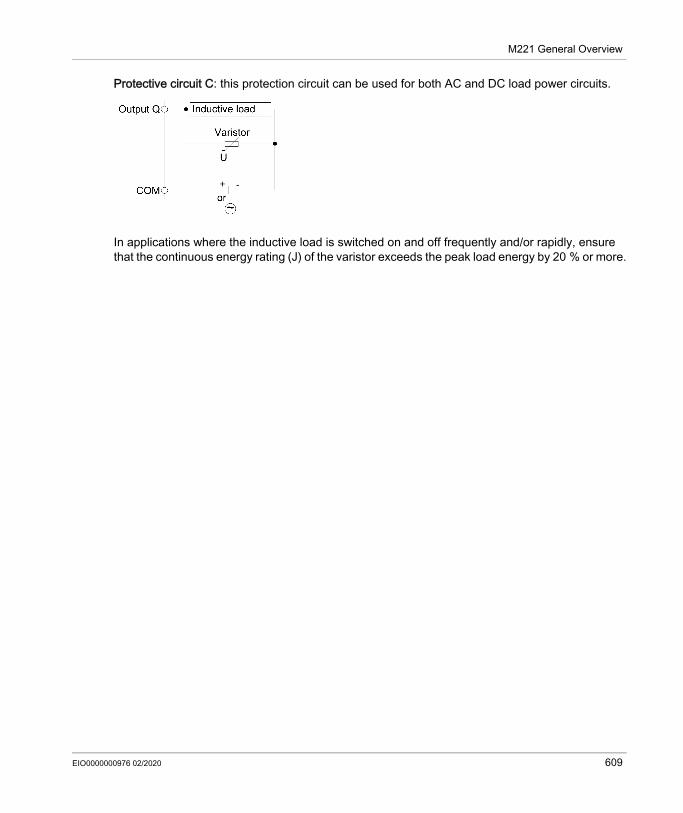
M221 General Overview
Protective circuit C: this protection circuit can be used for both AC and DC load power circuits.
In applications where the inductive load is switched on and off frequently and/or rapidly, ensure that the continuous energy rating (J) of the varistor exceeds the peak load energy by 20 % or more.
EIO0000000976 02/2020 609

M221 General Overview
DC Power Supply Characteristics and Wiring
OverviewThis section provides the characteristics and the wiring diagrams of the DC power supply.
DC Power Supply Voltage RangeIf the specified voltage range is not maintained, outputs may not switch as expected. Use appropriate safety interlocks and voltage monitoring circuits.
DANGERFIRE HAZARD Use only the correct wire sizes for the current capacity of the I/O channels and power supplies. For relay output (2 A) wiring, use conductors of at least 0.5 mm2 (AWG 20) with a temperature
rating of at least 80 °C (176 °F). For common conductors of relay output wiring (7 A), or relay output wiring greater than 2 A,
use conductors of at least 1.0 mm2 (AWG 16) with a temperature rating of at least 80 °C (176 °F).
Failure to follow these instructions will result in death or serious injury.
WARNINGUNINTENDED EQUIPMENT OPERATIONDo not exceed any of the rated values specified in the environmental and electrical characteristics tables.Failure to follow these instructions can result in death, serious injury, or equipment damage.
610 EIO0000000976 02/2020

M221 General Overview
DC Power Supply RequirementsThe M221 Logic Controller and associated I/O (TM2, TM3 and embedded I/O) require power supplies with a nominal voltage of 24 Vdc. The 24 Vdc power supplies must be rated Safety Extra Low Voltage (SELV) or Protective Extra Low Voltage (PELV) according to IEC 61140. These power supplies are isolated between the electrical input and output circuits of the power supply.
1For compliance to UL (Underwriters Laboratories) requirements, the power supply must also be of a type Class 2 with a maximum power output availability of less than 100 VA (approximately 4 A at nominal voltage). A Class 2 circuit requires dry indoor use only in non-hazardous locations, and must be grounded. You must separate Class 2 circuits from other circuits. If a non-Class 2 power source is used, either power supply or transformer, you must impose a current limiting device such as a fuse or a circuit breaker with a maximum rating of 4 A, but never exceeding the limits indicated in the electric characteristics and wiring diagrams for this equipment. If the indicated rating of the electrical characteristics or wiring diagrams are greater than 4 A, multiple Class 2 power supplies may be used.
Controller DC CharacteristicsThe following table shows the DC power supply characteristics:
WARNINGPOTENTIAL OF OVERHEATING AND FIRE Do not connect the equipment directly to line voltage. Use only isolating PELV or SELV power supplies to supply power to the equipment1.Failure to follow these instructions can result in death, serious injury, or equipment damage.
Characteristic ValueRated voltage 24 VdcPower supply voltage range 20.4...28.8 VdcPower interruption time 10 ms at 24 VdcMaximum inrush current 35 A
EIO0000000976 02/2020 611

M221 General Overview
Power interruptionThe TM221M Logic Controller must be supplied by an external 24 V power supply equipment. During power interruptions, the TM221M Logic Controller, associated to the suitable power supply, is able to continue normal operation for a minimum of 10 ms as specified by IEC standards.When planning the management of the power supplied to the controller, you must consider the power interruption duration due to the fast cycle time of the controller.There could potentially be many scans of the logic and consequential updates to the I/O image table during the power interruption, while there is no external power supplied to the inputs, the outputs or both depending on the power system architecture and power interruption circumstances.
Maximum power consumption TM221C16T with 4 expansion modules 10 WTM221CE16T 11 WTM221C16U 10 WTM221CE16U 11 WTM221C24T with 7 expansion modules 13 WTM221CE24T 14 WTM221C24U 13 WTM221CE24U 14 WTM221C40T 16 WTM221CE40T 17 WTM221C40U 16 WTM221CE40U 17 W
Maximum power consumption TM221M16R• with 7 expansion modules 22.5 WTM221ME16R• 23.3 WTM221M16T• 22 WTM221ME16T• 22.9 WTM221M32TK 22.3 WTM221ME32TK 23.2 W
Isolation between DC power supply and internal logic
TM221C Logic Controller 500 Vac TM221M Logic Controller Not isolated
between DC power supply and protective earth ground (PE)
500 Vac
Characteristic Value
612 EIO0000000976 02/2020

M221 General Overview
DC Power Supply Wiring DiagramThe following figure shows the power supply terminal block removal procedure:
The following figure shows the wiring of the DC power supply:
* Type T fuse
For more information, refer to the 5.08 pitch Rules for Removable Screw Terminal block (see page 604).
WARNINGUNINTENDED EQUIPMENT OPERATION Individually monitor each source of power used in the controller system including input power
supplies, output power supplies and the power supply to the controller to allow appropriate system shutdown during power system interruptions.
The inputs monitoring each of the power supply sources must be unfiltered inputs.Failure to follow these instructions can result in death, serious injury, or equipment damage.
EIO0000000976 02/2020 613

M221 General Overview
AC Power Supply Characteristics and Wiring
OverviewThis section provides the wiring diagrams and the characteristics of the AC power supply.
AC Power Supply Voltage RangeIf the specified voltage range is not maintained, outputs may not switch as expected. Use appropriate safety interlocks and voltage monitoring circuits.
Controller AC CharacteristicsThe following table shows the AC power supply characteristics:
DANGERFIRE HAZARD Use only the correct wire sizes for the current capacity of the I/O channels and power supplies. For relay output (2 A) wiring, use conductors of at least 0.5 mm2 (AWG 20) with a temperature
rating of at least 80 °C (176 °F). For common conductors of relay output wiring (7 A), or relay output wiring greater than 2 A,
use conductors of at least 1.0 mm2 (AWG 16) with a temperature rating of at least 80 °C (176 °F).
Failure to follow these instructions will result in death or serious injury.
WARNINGUNINTENDED EQUIPMENT OPERATIONDo not exceed any of the rated values specified in the environmental and electrical characteristics tables.Failure to follow these instructions can result in death, serious injury, or equipment damage.
Characteristic ValueVoltage rated 100...240 Vac
limit (including ripple) 85...264 VacFrequency rated 50/60 Hz
limit 45/66 HzPower interruption time 10 ms at 100 VacMaximum inrush current
at 240 Vac 40 A
614 EIO0000000976 02/2020

M221 General Overview
Power interruptionThe duration of power interruptions where the M221 Logic Controller is able to continue normal operation varies depending upon the load to the power supply of the controller, but generally a minimum of 10 ms is maintained as specified by IEC standards.If there is a minimum load on the controller power supply, the interruption can be as long as 400 ms.When planning the management of the power supplied to the controller, you must consider the duration due to the fast cycle time.There could potentially be many scans of the logic and consequential updates to the I/O image table during the power interruption, while there is no external power supplied to the inputs, the outputs or both depending on the power system architecture and power interruption circumstances.
Maximum power consumption at 100...240 Vac
TM221C16R with 4 expansion modules
46 VATM221CE16R 49 VATM221C24R with 7 expansion
modules55 VA
TM221CE24R 58 VATM221C40R 67 VATM221CE40R 70 VA
Isolation between AC power supply and internal logic 2300 Vacbetween AC power supply and protective earth ground (PE) 1500 Vac
Characteristic Value
WARNINGUNINTENDED EQUIPMENT OPERATION Individually monitor each source of power used in the Modicon M221 Logic Controller system
including input power supplies, output power supplies and the power supply to the controller to allow appropriate system shutdown during power system interruptions.
The inputs monitoring each of the power supply sources must be unfiltered inputs.Failure to follow these instructions can result in death, serious injury, or equipment damage.
EIO0000000976 02/2020 615
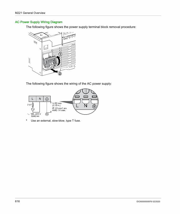
M221 General Overview
AC Power Supply Wiring DiagramThe following figure shows the power supply terminal block removal procedure:
The following figure shows the wiring of the AC power supply:
* Use an external, slow-blow, type T fuse.
616 EIO0000000976 02/2020

M221 General Overview
Grounding the M221 System
OverviewTo help minimize the effects of electromagnetic interference, cables carrying the fast I/O, analog I/O, and field bus communication signals must be shielded.
1Multipoint grounding is permissible if connections are made to an equipotential ground plane dimensioned to help avoid cable shield damage in the event of power system short-circuit currents.The use of shielded cables requires compliance with the following wiring rules: For protective ground connections (PE), metal conduit or ducting can be used for part of the
shielding length, provided there is no break in the continuity of the ground connections. For functional ground (FE), the shielding is intended to attenuate electromagnetic interference and the shielding must be continuous for the length of the cable. If the purpose is both functional and protective, as is often the case for communication cables, the cable must have continuous shielding.
Wherever possible, keep cables carrying one type of signal separate from the cables carrying other types of signals or power.
Protective Ground (PE) on the BackplaneThe protective ground (PE) is connected to the conductive backplane by a heavy-duty wire, usually a braided copper cable with the maximum allowable cable section.
WARNINGUNINTENDED EQUIPMENT OPERATION Use shielded cables for all fast I/O, analog I/O, and communication signals. Ground cable shields for all fast I/O, analog I/O, and communication signals at a single point1. Route communications and I/O cables separately from power cables.Failure to follow these instructions can result in death, serious injury, or equipment damage.
EIO0000000976 02/2020 617

M221 General Overview
Shielded Cables ConnectionsCables carrying the fast I/O, analog I/O, and field bus communication signals must be shielded. The shielding must be securely connected to ground. The fast I/O and analog I/O shields may be connected either to the functional ground (FE) or to the protective ground (PE) of your M221 Logic Controller. The field bus communication cable shields must be connected to the protective ground (PE) with a connecting clamp secured to the conductive backplane of your installation.The shielding of the Modbus cable must be connected to the protective ground (PE).
Protective Ground (PE) Cable ShieldingTo ground the shield of a cable through a grounding clamp:
NOTE: The shielding must be clamped securely to the conductive backplane to ensure a good contact.
DANGERELECTRIC SHOCKMake sure that Modbus cables are securely connected to the protective ground (PE).Failure to follow these instructions will result in death or serious injury.
Step Description1 Strip the shielding for a length of
15 mm (0.59 in.)
2 Attach the cable to the conductive backplane plate by attaching the grounding clamp to the stripped part of the shielding as close as possible to the M221 Logic Controller system base.
618 EIO0000000976 02/2020

M221 General Overview
Functional Ground (FE) Cable ShieldingTo connect the shield of a cable through the Grounding Bar:
Step Description1 Install the
Grounding Bar directly on the conductive backplane below the M221 Logic Controller system as illustrated.
2 Strip the shielding for a length of 15 mm (0.59 in.
3 Tightly clamp on the blade connector (1) using nylon fastener (2)(width 2.5...3 mm (0.1...0.12 in.)) and appropriate tool.
EIO0000000976 02/2020 619

M221 General Overview
NOTE: Use the TM2XMTGB Grounding Bar exclusively for Functional Ground (FE) connections.
WARNINGACCIDENTAL DISCONNECTION FROM PROTECTIVE GROUND (PE) Do not use the TM2XMTGB Grounding Plate to provide a protective ground (PE). Use the TM2XMTGB Grounding Plate only to provide a functional ground (FE).Failure to follow these instructions can result in death, serious injury, or equipment damage.
620 EIO0000000976 02/2020

Modicon M221Modicon TM221C Logic ControllerEIO0000000976 02/2020
Modicon TM221C Logic Controller
Chapter 10Modicon TM221C Logic Controller
What Is in This Chapter?This chapter contains the following sections:
Section Topic Page10.1 Modicon TM221C Logic Controller Presentation 62210.2 Embedded I/O Channels 705
EIO0000000976 02/2020 621

Modicon TM221C Logic Controller
Modicon TM221C Logic Controller Presentation
Section 10.1Modicon TM221C Logic Controller Presentation
What Is in This Section?This section contains the following topics:
Topic PageTM221C16R Presentation 623TM221CE16R Presentation 628TM221C16T Presentation 632TM221CE16T Presentation 636TM221C16U Presentation 640TM221CE16U Presentation 644TM221C24R Presentation 649TM221CE24R Presentation 653TM221C24T Presentation 657TM221CE24T Presentation 661TM221C24U Presentation 665TM221CE24U Presentation 670TM221C40R Presentation 675TM221CE40R Presentation 680TM221C40T Presentation 685TM221CE40T Presentation 690TM221C40U Presentation 695TM221CE40U Presentation 700
622 EIO0000000976 02/2020

Modicon TM221C Logic Controller
TM221C16R Presentation
OverviewThe following features are integrated into the TM221C16R logic controller: 9 digital inputs 4 fast inputs (HSC) 5 regular inputs
7 digital outputs 7 relay outputs
2 analog inputs Communication ports 1 serial line port 1 USB mini-B programming port
The following figure shows the different components of the logic controllers:
EIO0000000976 02/2020 623

Modicon TM221C Logic Controller
N° Description Refer to1 Status LEDs –2 Output removable terminal block Rules for Removable Screw Terminal
Block (see page 604)3 Clip-on lock for 35 mm (1.38 in.) top hat section rail (DIN-rail) DIN Rail (see page 593)4 100...240 Vac power supply Power supply (see page 616)5 USB mini-B programming port / For terminal connection to a
programming PC (EcoStruxure Machine Expert - Basic)USB mini-B programming port (see page 867)
6 Serial line port 1 / RJ45 connector (RS-232 or RS-485) Serial line 1 (see page 872)7 SD Card slot SD Card Slot (see page 571)8 2 analog inputs Analog Inputs (see page 738)9 Run/Stop switch Run/Stop switch (see page 568)10 Input removable terminal block and embedded power supply
used for connecting sensors to the inputs. (1)Rules for Removable Screw Terminal Block (see page 604)
11 I/O expansion connector –12 Cartridge slot –13 Protective cover (SD Card slot, Run/Stop switch and USB mini-
B programming port)–
14 Locking hook –15 Removable analog inputs cover –16 Battery holder Installing and Replacing the Battery
(see page 553)(1) Embedded power supply characteristics: Voltage: 24 V -15%...+10% isolated Imax: 250 mA No protection and no overload detection
Refer to Embedded I/O Channels (see page 705).
624 EIO0000000976 02/2020

Modicon TM221C Logic Controller
Status LEDsThe following figure shows the status LEDs:
The following table describes the status LEDs:
Label Function Type Color Status Description
Controller States(1) Prg Port Communication
Application Execution
PWR Power Green On Indicates that power is applied.Off Indicates that power is removed.
RUN Machine Status Green On Indicates that the controller is running a valid application.
Flashing Indicates that the controller has a valid application that is stopped.
Off Indicates that the controller is not programmed.ERR Error Red On* EXCEPTION Restricted NO
Flashing (with RUN status LED Off)
INTERNAL ERROR
Restricted NO
Slow flash Minor error detected(2)
Yes Depends on the RUN status LED
1 single flash No application Yes Yes* ERR LED is also On during booting process.
NOTE: For information about the LEDs integrated into the Ethernet connector, refer to Ethernet Status LEDs (see page 871)(1) For more information about the controller state description, refer to the M221 Logic Controller - Programming Guide (see page 62).(2) The controller detected an error but remains in RUNNING state. The ERR LED on the controller flashes. For more information, refer to M221 Logic Controller - Programming Guide (see page 213).
EIO0000000976 02/2020 625

Modicon TM221C Logic Controller
SD SD Card Access (see page 571)
Green On Indicates that the SD card is being accessed.Flashing Indicates that an error was detected during the SD card
operation.Off Indicates no access (idle) or no card is present.
BAT Battery (see page 553)
Red On Indicates that the battery needs to be replaced.Flashing Indicates that the battery charge is low.Off Indicates that the battery is OK.
SL Serial line 1 (see page 872)
Green On Indicates the status of Serial line 1.Flashing Indicates activity on Serial line 1.Off Indicates no serial communication.
Label Function Type Color Status Description
Controller States(1) Prg Port Communication
Application Execution
* ERR LED is also On during booting process.
NOTE: For information about the LEDs integrated into the Ethernet connector, refer to Ethernet Status LEDs (see page 871)(1) For more information about the controller state description, refer to the M221 Logic Controller - Programming Guide (see page 62).(2) The controller detected an error but remains in RUNNING state. The ERR LED on the controller flashes. For more information, refer to M221 Logic Controller - Programming Guide (see page 213).
626 EIO0000000976 02/2020

Modicon TM221C Logic Controller
DimensionsThe following figure show the external dimensions of the logic controller:
EIO0000000976 02/2020 627

Modicon TM221C Logic Controller
TM221CE16R Presentation
OverviewThe following features are integrated into the TM221CE16R logic controller: 9 digital inputs 4 fast inputs (HSC) 5 regular inputs
7 digital outputs 7 relay outputs
2 analog inputs Communication ports 1 serial line port 1 USB mini-B programming port 1 Ethernet port
DescriptionThe following figure shows the different components of the logic controller:
628 EIO0000000976 02/2020

Modicon TM221C Logic Controller
N° Description Refer to1 Status LEDs –2 Output removable terminal block Rules for Removable Screw Terminal
Block (see page 604)3 Clip-on lock for 35 mm (1.38 in.) top hat section rail (DIN-rail) DIN Rail (see page 593)4 Ethernet port / RJ45 connector Ethernet port (see page 869)5 100...240 Vac power supply Power supply (see page 616)6 USB mini-B programming port / For terminal connection to a
programming PC (EcoStruxure Machine Expert - Basic)USB mini-B programming port (see page 867)
7 Serial line port 1 / RJ45 connector (RS-232 or RS-485) Serial line 1 (see page 872)8 SD Card slot SD Card Slot (see page 571)9 2 analog inputs Analog Inputs (see page 738)10 Run/Stop switch Run/Stop switch (see page 568)11 Input removable terminal block and embedded power supply
used for connecting sensors to the inputs.(1)Rules for Removable Screw Terminal Block (see page 604)
12 I/O expansion connector –13 Cartridge slot –14 Protective cover (SD Card slot, Run/Stop switch and USB mini-
B programming port)–
15 Locking hook –16 Removable analog inputs cover –17 Battery holder Installing and Replacing the Battery
(see page 553)(1) Embedded power supply characteristics: Voltage: 24 V -15%...+10% isolated Imax: 250 mA No protection and no overload detection
Refer to Embedded I/O Channels (see page 705).
EIO0000000976 02/2020 629

Modicon TM221C Logic Controller
Status LEDsThe following figure shows the status LEDs:
The following table describes the status LEDs:
Label Function Type Color Status Description
Controller States(1) Prg Port Communication
Application Execution
PWR Power Green On Indicates that power is applied.Off Indicates that power is removed.
RUN Machine Status
Green On Indicates that the controller is running a valid application.
Flashing Indicates that the controller has a valid application that is stopped.
Off Indicates that the controller is not programmed.ERR Error Red On* EXCEPTION Restricted NO
Flashing (with RUN status LED Off)
INTERNAL ERROR
Restricted NO
Slow flash Minor error detected(2)
Yes Depends on the RUN status LED
1 single flash No application Yes Yes* ERR LED is also On during booting process.
NOTE: For information about the LEDs integrated into the Ethernet connector, refer to Ethernet Status LEDs (see page 871)(1) For more information about the controller state description, refer to the M221 Logic Controller - Programming Guide (see page 62).(2) The controller detected an error but remains in RUNNING state. The ERR LED on the controller flashes. For more information, refer to M221 Logic Controller - Programming Guide (see page 213).
630 EIO0000000976 02/2020

Modicon TM221C Logic Controller
DimensionsThe following figure shows the external dimensions of the logic controllers:
SD SD Card Access (see page 571)
Green On Indicates that the SD card is being accessed.Flashing Indicates that an error was detected during the SD card
operation.Off Indicates no access (idle) or no card is present.
BAT Battery (see page 553)
Red On Indicates that the battery needs to be replaced.Flashing Indicates that the battery charge is low.Off Indicates that the battery is OK.
SL Serial line 1 (see page 872)
Green On Indicates the status of Serial line 1.Flashing Indicates activity on Serial line 1.Off Indicates no serial communication.
Label Function Type Color Status Description
Controller States(1) Prg Port Communication
Application Execution
* ERR LED is also On during booting process.
NOTE: For information about the LEDs integrated into the Ethernet connector, refer to Ethernet Status LEDs (see page 871)(1) For more information about the controller state description, refer to the M221 Logic Controller - Programming Guide (see page 62).(2) The controller detected an error but remains in RUNNING state. The ERR LED on the controller flashes. For more information, refer to M221 Logic Controller - Programming Guide (see page 213).
EIO0000000976 02/2020 631

Modicon TM221C Logic Controller
TM221C16T Presentation
OverviewThe following features are integrated into the TM221C16T logic controller: 9 digital inputs 4 fast inputs (HSC) 5 regular inputs
7 digital outputs 2 fast source transistor outputs 5 regular source transistor outputs
2 analog inputs Communication ports 1 serial line port 1 USB mini-B programming port
DescriptionThe following figure shows the different components of the logic controllers:
632 EIO0000000976 02/2020

Modicon TM221C Logic Controller
N° Description Refer to1 Status LEDs –2 Output removable terminal block Rules for Removable Screw Terminal
Block (see page 604)3 Clip-on lock for 35 mm (1.38 in.) top hat section rail (DIN-rail) DIN Rail (see page 593)4 24 Vdc power supply Power supply (see page 610)5 USB mini-B programming port / For terminal connection to a
programming PC (EcoStruxure Machine Expert - Basic)USB mini-B programming port (see page 867)
6 Serial line port 1 / RJ45 connector (RS-232 or RS-485) Serial line 1 (see page 872)7 SD Card slot SD Card Slot (see page 571)8 2 analog inputs Analog Inputs (see page 738)9 Run/Stop switch Run/Stop switch (see page 568)10 Input removable terminal block Rules for Removable Screw Terminal
Block (see page 604)11 I/O expansion connector –12 Cartridge slot –13 Protective cover (SD Card slot, Run/Stop switch and USB mini-
B programming port)–
14 Locking hook –15 Removable analog inputs cover –16 Battery holder Installing and Replacing the Battery
(see page 553)
EIO0000000976 02/2020 633

Modicon TM221C Logic Controller
Status LEDsThe following figure shows the status LEDs:
The following table describes the status LEDs:
Label Function Type Color Status Description
Controller States(1) Prg Port Communication
Application Execution
PWR Power Green On Indicates that power is applied.Off Indicates that power is removed.
RUN Machine Status Green On Indicates that the controller is running a valid application.
Flashing Indicates that the controller has a valid application that is stopped.
Off Indicates that the controller is not programmed.ERR Error Red On* EXCEPTION Restricted NO
Flashing (with RUN status LED Off)
INTERNAL ERROR
Restricted NO
Slow flash Minor error detected(2)
Yes Depends on the RUN status LED
1 single flash No application Yes Yes* ERR LED is also On during booting process.
NOTE: For information about the LEDs integrated into the Ethernet connector, refer to Ethernet Status LEDs (see page 871)(1) For more information about the controller state description, refer to the M221 Logic Controller - Programming Guide (see page 62).(2) The controller detected an error but remains in RUNNING state. The ERR LED on the controller flashes. For more information, refer to M221 Logic Controller - Programming Guide (see page 213).
634 EIO0000000976 02/2020

Modicon TM221C Logic Controller
DimensionsThe following figure shows the external dimensions of the logic controllers:
SD SD Card Access (see page 571)
Green On Indicates that the SD card is being accessed.Flashing Indicates that an error was detected during the SD card
operation.Off Indicates no access (idle) or no card is present.
BAT Battery (see page 553)
Red On Indicates that the battery needs to be replaced.Flashing Indicates that the battery charge is low.Off Indicates that the battery is OK.
SL Serial line 1 (see page 872)
Green On Indicates the status of Serial line 1.Flashing Indicates activity on Serial line 1.Off Indicates no serial communication.
Label Function Type Color Status Description
Controller States(1) Prg Port Communication
Application Execution
* ERR LED is also On during booting process.
NOTE: For information about the LEDs integrated into the Ethernet connector, refer to Ethernet Status LEDs (see page 871)(1) For more information about the controller state description, refer to the M221 Logic Controller - Programming Guide (see page 62).(2) The controller detected an error but remains in RUNNING state. The ERR LED on the controller flashes. For more information, refer to M221 Logic Controller - Programming Guide (see page 213).
EIO0000000976 02/2020 635

Modicon TM221C Logic Controller
TM221CE16T Presentation
OverviewThe following features are integrated into the TM221CE16T logic controller: 9 digital inputs 4 fast inputs (HSC) 5 regular inputs
7 digital outputs 2 fast source transistor outputs 5 regular source transistor outputs
2 analog inputs Communication ports 1 serial line port 1 USB mini-B programming port 1 Ethernet port
DescriptionThe following figure shows the different components of the logic controllers:
636 EIO0000000976 02/2020

Modicon TM221C Logic Controller
N° Description Refer to1 Status LEDs –2 Output removable terminal block Rules for Removable Screw Terminal
Block (see page 604)3 Clip-on lock for 35 mm (1.38 in.) top hat section rail (DIN-rail) DIN Rail (see page 593)4 Ethernet port / RJ45 connector Ethernet port (see page 869)5 24 Vdc power supply Power supply (see page 610)6 USB mini-B programming port / For terminal connection to a
programming PC (EcoStruxure Machine Expert - Basic)USB mini-B programming port (see page 867)
7 Serial line port 1 / RJ45 connector (RS-232 or RS-485) Serial line 1 (see page 872)8 SD Card slot SD Card Slot (see page 571)9 2 analog inputs Analog Inputs (see page 738)10 Run/Stop switch Run/Stop switch (see page 568)11 Input removable terminal block Rules for Removable Screw Terminal
Block (see page 604)12 I/O expansion connector –13 Cartridge slot –14 Protective cover (SD Card slot, Run/Stop switch and USB mini-
B programming port)–
15 Locking hook –16 Removable analog inputs cover –17 Battery holder Installing and Replacing the Battery
(see page 553)
EIO0000000976 02/2020 637

Modicon TM221C Logic Controller
Status LEDsThe following figure shows the status LEDs:
The following table describes the status LEDs:
Label Function Type Color Status Description
Controller States(1) Prg Port Communication
Application Execution
PWR Power Green On Indicates that power is applied.Off Indicates that power is removed.
RUN Machine Status Green On Indicates that the controller is running a valid application.
Flashing Indicates that the controller has a valid application that is stopped.
Off Indicates that the controller is not programmed.ERR Error Red On* EXCEPTION Restricted NO
Flashing (with RUN status LED Off)
INTERNAL ERROR
Restricted NO
Slow flash Minor error detected(2)
Yes Depends on the RUN status LED
1 single flash No application Yes Yes* ERR LED is also On during booting process.
NOTE: For information about the LEDs integrated into the Ethernet connector, refer to Ethernet Status LEDs (see page 871)(1) For more information about the controller state description, refer to the M221 Logic Controller - Programming Guide (see page 62).(2) The controller detected an error but remains in RUNNING state. The ERR LED on the controller flashes. For more information, refer to M221 Logic Controller - Programming Guide (see page 213).
638 EIO0000000976 02/2020

Modicon TM221C Logic Controller
DimensionsThe following figure shows the external dimensions of the logic controllers:
SD SD Card Access (see page 571)
Green On Indicates that the SD card is being accessed.Flashing Indicates that an error was detected during the SD card
operation.Off Indicates no access (idle) or no card is present.
BAT Battery (see page 553)
Red On Indicates that the battery needs to be replaced.Flashing Indicates that the battery charge is low.Off Indicates that the battery is OK.
SL Serial line 1 (see page 872)
Green On Indicates the status of Serial line 1.Flashing Indicates activity on Serial line 1.Off Indicates no serial communication.
Label Function Type Color Status Description
Controller States(1) Prg Port Communication
Application Execution
* ERR LED is also On during booting process.
NOTE: For information about the LEDs integrated into the Ethernet connector, refer to Ethernet Status LEDs (see page 871)(1) For more information about the controller state description, refer to the M221 Logic Controller - Programming Guide (see page 62).(2) The controller detected an error but remains in RUNNING state. The ERR LED on the controller flashes. For more information, refer to M221 Logic Controller - Programming Guide (see page 213).
EIO0000000976 02/2020 639

Modicon TM221C Logic Controller
TM221C16U Presentation
OverviewThe following features are integrated into the TM221C16U logic controller: 9 digital inputs 4 fast inputs (HSC) 5 regular inputs
7 digital outputs 2 fast sink transistor outputs 5 regular sink transistor outputs
2 analog inputs Communication ports 1 serial line port 1 USB mini-B programming port
DescriptionThe following figure shows the different components of the logic controllers:
640 EIO0000000976 02/2020

Modicon TM221C Logic Controller
N° Description Refer to1 Status LEDs –2 Output removable terminal block Rules for Removable Screw Terminal
Block (see page 604)3 Clip-on lock for 35 mm (1.38 in.) top hat section rail (DIN-rail) DIN Rail (see page 593)4 24 Vdc power supply Power supply (see page 610)5 USB mini-B programming port / For terminal connection to a
programming PC (EcoStruxure Machine Expert - Basic)USB mini-B programming port (see page 867)
6 Serial line port 1 / RJ45 connector (RS-232 or RS-485) Serial line 1 (see page 872)7 SD Card slot SD Card Slot (see page 571)8 2 analog inputs Analog Inputs (see page 738)9 Run/Stop switch Run/Stop switch (see page 568)10 Input removable terminal block Rules for Removable Screw Terminal
Block (see page 604)11 I/O expansion connector –12 Cartridge slot –13 Protective cover (SD Card slot, Run/Stop switch and USB mini-
B programming port)–
14 Locking hook –15 Removable analog inputs cover –16 Battery holder Installing and Replacing the Battery
(see page 553)
EIO0000000976 02/2020 641

Modicon TM221C Logic Controller
Status LEDsThe following figure shows the status LEDs:
The following table describes the status LEDs:
Label Function Type Color Status Description
Controller States(1) Prg Port Communication
Application Execution
PWR Power Green On Indicates that power is applied.Off Indicates that power is removed.
RUN Machine Status Green On Indicates that the controller is running a valid application.
Flashing Indicates that the controller has a valid application that is stopped.
Off Indicates that the controller is not programmed.ERR Error Red On* EXCEPTION Restricted NO
Flashing (with RUN status LED Off)
INTERNAL ERROR
Restricted NO
Slow flash Minor error detected(2)
Yes Depends on the RUN status LED
1 single flash No application Yes Yes* ERR LED is also On during booting process.
NOTE: For information about the LEDs integrated into the Ethernet connector, refer to Ethernet Status LEDs (see page 871)(1) For more information about the controller state description, refer to the M221 Logic Controller - Programming Guide (see page 62).(2) The controller detected an error but remains in RUNNING state. The ERR LED on the controller flashes. For more information, refer to M221 Logic Controller - Programming Guide (see page 213).
642 EIO0000000976 02/2020

Modicon TM221C Logic Controller
DimensionsThe following figure shows the external dimensions of the logic controllers:
SD SD Card Access (see page 571)
Green On Indicates that the SD card is being accessed.Flashing Indicates that an error was detected during the SD card
operation.Off Indicates no access (idle) or no card is present.
BAT Battery (see page 553)
Red On Indicates that the battery needs to be replaced.Flashing Indicates that the battery charge is low.Off Indicates that the battery is OK.
SL Serial line 1 (see page 872)
Green On Indicates the status of Serial line 1.Flashing Indicates activity on Serial line 1.Off Indicates no serial communication.
Label Function Type Color Status Description
Controller States(1) Prg Port Communication
Application Execution
* ERR LED is also On during booting process.
NOTE: For information about the LEDs integrated into the Ethernet connector, refer to Ethernet Status LEDs (see page 871)(1) For more information about the controller state description, refer to the M221 Logic Controller - Programming Guide (see page 62).(2) The controller detected an error but remains in RUNNING state. The ERR LED on the controller flashes. For more information, refer to M221 Logic Controller - Programming Guide (see page 213).
EIO0000000976 02/2020 643

Modicon TM221C Logic Controller
TM221CE16U Presentation
OverviewThe following features are integrated into the TM221CE16U logic controller: 9 digital inputs 4 fast inputs (HSC) 5 regular inputs
7 digital outputs 2 fast sink transistor outputs 5 regular sink transistor outputs
2 analog inputs Communication ports 1 serial line port 1 USB mini-B programming port 1 Ethernet port
644 EIO0000000976 02/2020

Modicon TM221C Logic Controller
DescriptionThe following figure shows the different components of the logic controllers:
N° Description Refer to1 Status LEDs –2 Output removable terminal block Rules for Removable Screw Terminal
Block (see page 604)3 Clip-on lock for 35 mm (1.38 in.) top hat section rail (DIN-rail) DIN Rail (see page 593)4 Ethernet port / RJ45 connector Ethernet port (see page 869)
EIO0000000976 02/2020 645

Modicon TM221C Logic Controller
5 24 Vdc power supply Power supply (see page 610)6 USB mini-B programming port / For terminal connection to a
programming PC (EcoStruxure Machine Expert - Basic)USB mini-B programming port (see page 867)
7 Serial line port 1 / RJ45 connector (RS-232 or RS-485) Serial line 1 (see page 872)8 SD Card slot SD Card Slot (see page 571)9 2 analog inputs Analog Inputs (see page 738)10 Run/Stop switch Run/Stop switch (see page 568)11 Input removable terminal block Rules for Removable Screw Terminal
Block (see page 604)12 I/O expansion connector –13 Cartridge slot –14 Protective cover (SD Card slot, Run/Stop switch and USB mini-
B programming port)–
15 Locking hook –16 Removable analog inputs cover –17 Battery holder Installing and Replacing the Battery
(see page 553)
N° Description Refer to
646 EIO0000000976 02/2020

Modicon TM221C Logic Controller
Status LEDsThe following figure shows the status LEDs:
The following table describes the status LEDs:
Label Function Type Color Status Description
Controller States(1) Prg Port Communication
Application Execution
PWR Power Green On Indicates that power is applied.Off Indicates that power is removed.
RUN Machine Status Green On Indicates that the controller is running a valid application.
Flashing Indicates that the controller has a valid application that is stopped.
Off Indicates that the controller is not programmed.ERR Error Red On* EXCEPTION Restricted NO
Flashing (with RUN status LED Off)
INTERNAL ERROR
Restricted NO
Slow flash Minor error detected(2)
Yes Depends on the RUN status LED
1 single flash No application Yes Yes* ERR LED is also On during booting process.
NOTE: For information about the LEDs integrated into the Ethernet connector, refer to Ethernet Status LEDs (see page 871)(1) For more information about the controller state description, refer to the M221 Logic Controller - Programming Guide (see page 62).(2) The controller detected an error but remains in RUNNING state. The ERR LED on the controller flashes. For more information, refer to M221 Logic Controller - Programming Guide (see page 213).
EIO0000000976 02/2020 647

Modicon TM221C Logic Controller
DimensionsThe following figure shows the external dimensions of the logic controllers:
SD SD Card Access (see page 571)
Green On Indicates that the SD card is being accessed.Flashing Indicates that an error was detected during the SD card
operation.Off Indicates no access (idle) or no card is present.
BAT Battery (see page 553)
Red On Indicates that the battery needs to be replaced.Flashing Indicates that the battery charge is low.Off Indicates that the battery is OK.
SL Serial line 1 (see page 872)
Green On Indicates the status of Serial line 1.Flashing Indicates activity on Serial line 1.Off Indicates no serial communication.
Label Function Type Color Status Description
Controller States(1) Prg Port Communication
Application Execution
* ERR LED is also On during booting process.
NOTE: For information about the LEDs integrated into the Ethernet connector, refer to Ethernet Status LEDs (see page 871)(1) For more information about the controller state description, refer to the M221 Logic Controller - Programming Guide (see page 62).(2) The controller detected an error but remains in RUNNING state. The ERR LED on the controller flashes. For more information, refer to M221 Logic Controller - Programming Guide (see page 213).
648 EIO0000000976 02/2020

Modicon TM221C Logic Controller
TM221C24R Presentation
OverviewThe following features are integrated into the TM221C24R logic controller: 14 digital inputs 4 fast inputs (HSC) 10 regular inputs
10 digital outputs 10 relay outputs
2 analog inputs Communication ports 1 serial line port 1 USB mini-B programming port
DescriptionThe following figure shows the different components of the logic controller:
EIO0000000976 02/2020 649

Modicon TM221C Logic Controller
N° Description Refer to1 Status LEDs –2 Output removable terminal block Rules for Removable Screw Terminal
Block (see page 604)3 Clip-on lock for 35 mm (1.38 in.) top hat section rail (DIN-rail) DIN Rail (see page 593)4 100...240 Vac power supply Power supply (see page 616)5 USB mini-B programming port / For terminal connection to a
programming PC (EcoStruxure Machine Expert - Basic)USB mini-B programming port (see page 867)
6 Serial line port 1 / RJ45 connector (RS-232 or RS-485) Serial line 1 (see page 872)7 SD Card slot SD Card Slot (see page 571)8 2 analog inputs Analog Inputs (see page 738)9 Run/Stop switch Run/Stop switch (see page 568)10 Input removable terminal block and embedded power supply
used for connecting sensors to the inputs. (1)Rules for Removable Screw Terminal Block (see page 604)
11 I/O expansion connector –12 Cartridge slot –13 Protective cover (SD Card slot, Run/Stop switch and USB mini-
B programming port)–
14 Locking hook –15 Removable analog inputs cover –16 Battery holder Installing and Replacing the Battery
(see page 553)(1) Embedded power supply characteristics: Voltage: 24 V -15%...+10% isolated Imax: 250 mA No protection and no overload detection
Refer to Embedded I/O Channels (see page 705).
650 EIO0000000976 02/2020

Modicon TM221C Logic Controller
Status LEDsThe following figure shows the status LEDs:
The following table describes the status LEDs:
Label Function Type Color Status Description
Controller States(1) Prg Port Communication
Application Execution
PWR Power Green On Indicates that power is applied.Off Indicates that power is removed.
RUN Machine Status Green On Indicates that the controller is running a valid application.
Flashing Indicates that the controller has a valid application that is stopped.
Off Indicates that the controller is not programmed.ERR Error Red On* EXCEPTION Restricted NO
Flashing (with RUN status LED Off)
INTERNAL ERROR
Restricted NO
Slow flash Minor error detected(2)
Yes Depends on the RUN status LED
1 single flash No application Yes Yes* ERR LED is also On during booting process.
NOTE: For information about the LEDs integrated into the Ethernet connector, refer to Ethernet Status LEDs (see page 871)(1) For more information about the controller state description, refer to the M221 Logic Controller - Programming Guide (see page 62).(2) The controller detected an error but remains in RUNNING state. The ERR LED on the controller flashes. For more information, refer to M221 Logic Controller - Programming Guide (see page 213).
EIO0000000976 02/2020 651

Modicon TM221C Logic Controller
DimensionsThe following figure shows the external dimensions of the logic controllers:
SD SD Card Access (see page 571)
Green On Indicates that the SD card is being accessed.Flashing Indicates that an error was detected during the SD card
operation.Off Indicates no access (idle) or no card is present.
BAT Battery (see page 553)
Red On Indicates that the battery needs to be replaced.Flashing Indicates that the battery charge is low.Off Indicates that the battery is OK.
SL Serial line 1 (see page 872)
Green On Indicates the status of Serial line 1.Flashing Indicates activity on Serial line 1.Off Indicates no serial communication.
Label Function Type Color Status Description
Controller States(1) Prg Port Communication
Application Execution
* ERR LED is also On during booting process.
NOTE: For information about the LEDs integrated into the Ethernet connector, refer to Ethernet Status LEDs (see page 871)(1) For more information about the controller state description, refer to the M221 Logic Controller - Programming Guide (see page 62).(2) The controller detected an error but remains in RUNNING state. The ERR LED on the controller flashes. For more information, refer to M221 Logic Controller - Programming Guide (see page 213).
652 EIO0000000976 02/2020

Modicon TM221C Logic Controller
TM221CE24R Presentation
OverviewThe following features are integrated into the TM221CE24R logic controller: 14 digital inputs 4 fast inputs (HSC) 10 regular inputs
10 digital outputs 10 relay outputs
2 analog inputs Communication ports 1 serial line port 1 USB mini-B programming port 1 Ethernet port
DescriptionThe following figure shows the different components of the logic controllers:
EIO0000000976 02/2020 653

Modicon TM221C Logic Controller
N° Description Refer to1 Status LEDs –2 Output removable terminal block Rules for Removable Screw Terminal
Block (see page 604)3 Clip-on lock for 35 mm (1.38 in.) top hat section rail (DIN-rail) DIN Rail (see page 593)4 Ethernet port / RJ45 connector Ethernet port (see page 869)5 100...240 Vac power supply Power supply (see page 616)6 USB mini-B programming port / For terminal connection to a
programming PC (EcoStruxure Machine Expert - Basic)USB mini-B programming port (see page 867)
7 Serial line port 1 / RJ45 connector (RS-232 or RS-485) Serial line 1 (see page 872)8 SD Card slot SD Card Slot (see page 571)9 2 analog inputs Analog Inputs (see page 738)10 Run/Stop switch Run/Stop switch (see page 568)11 Input removable terminal block and embedded power supply
used for connecting sensors to the inputs.(1)Rules for Removable Screw Terminal Block (see page 604)
12 I/O expansion connector –13 Cartridge slot –14 Protective cover (SD Card slot, Run/Stop switch and USB mini-
B programming port)–
15 Locking hook –16 Removable analog inputs cover –17 Battery holder Installing and Replacing the Battery
(see page 553)(1) Embedded power supply characteristics: Voltage: 24 V -15%...+10% isolated Imax: 250 mA No protection and no overload detection
Refer to Embedded I/O Channels (see page 705).
654 EIO0000000976 02/2020

Modicon TM221C Logic Controller
Status LEDsThe following figure shows the status LEDs:
The following table describes the status LEDs:
Label Function Type Color Status Description
Controller States(1) Prg Port Communication
Application Execution
PWR Power Green On Indicates that power is applied.Off Indicates that power is removed.
RUN Machine Status Green On Indicates that the controller is running a valid application.
Flashing Indicates that the controller has a valid application that is stopped.
Off Indicates that the controller is not programmed.ERR Error Red On* EXCEPTION Restricted NO
Flashing (with RUN status LED Off)
INTERNAL ERROR
Restricted NO
Slow flash Minor error detected(2)
Yes Depends on the RUN status LED
1 single flash No application Yes Yes* ERR LED is also On during booting process.
NOTE: For information about the LEDs integrated into the Ethernet connector, refer to Ethernet Status LEDs (see page 871)(1) For more information about the controller state description, refer to the M221 Logic Controller - Programming Guide (see page 62).(2) The controller detected an error but remains in RUNNING state. The ERR LED on the controller flashes. For more information, refer to M221 Logic Controller - Programming Guide (see page 213).
EIO0000000976 02/2020 655

Modicon TM221C Logic Controller
DimensionsThe following figure shows the external dimensions of the logic controllers:
SD SD Card Access (see page 571)
Green On Indicates that the SD card is being accessed.Flashing Indicates that an error was detected during the SD card
operation.Off Indicates no access (idle) or no card is present.
BAT Battery (see page 553)
Red On Indicates that the battery needs to be replaced.Flashing Indicates that the battery charge is low.Off Indicates that the battery is OK.
SL Serial line 1 (see page 872)
Green On Indicates the status of Serial line 1.Flashing Indicates activity on Serial line 1.Off Indicates no serial communication.
Label Function Type Color Status Description
Controller States(1) Prg Port Communication
Application Execution
* ERR LED is also On during booting process.
NOTE: For information about the LEDs integrated into the Ethernet connector, refer to Ethernet Status LEDs (see page 871)(1) For more information about the controller state description, refer to the M221 Logic Controller - Programming Guide (see page 62).(2) The controller detected an error but remains in RUNNING state. The ERR LED on the controller flashes. For more information, refer to M221 Logic Controller - Programming Guide (see page 213).
656 EIO0000000976 02/2020

Modicon TM221C Logic Controller
TM221C24T Presentation
OverviewThe following features are integrated into the TM221C24T logic controller: 14 digital inputs 4 fast inputs (HSC) 10 regular inputs
10 digital outputs 2 fast source transistor outputs 8 regular source transistor outputs
2 analog inputs Communication ports 1 serial line port 1 USB mini-B programming port
DescriptionThe following figure shows the different components of the logic controllers:
EIO0000000976 02/2020 657

Modicon TM221C Logic Controller
N° Description Refer to1 Status LEDs –2 Output removable terminal block Rules for Removable Screw Terminal
Block (see page 604)3 Clip-on lock for 35 mm (1.38 in.) top hat section rail (DIN-rail) DIN Rail (see page 593)4 24 Vdc power supply Power supply (see page 610)5 USB mini-B programming port / For terminal connection to a
programming PC (EcoStruxure Machine Expert - Basic)USB mini-B programming port (see page 867)
6 Serial line port 1 / RJ45 connector (RS-232 or RS-485) Serial line 1 (see page 872)7 SD Card slot SD Card Slot (see page 571)8 2 analog inputs Analog Inputs (see page 738)9 Run/Stop switch Run/Stop switch (see page 568)10 Input removable terminal block Rules for Removable Screw Terminal
Block (see page 604)11 I/O expansion connector –12 Cartridge slot –13 Protective cover (SD Card slot, Run/Stop switch and USB mini-
B programming port)–
14 Locking hook –15 Removable analog inputs cover –16 Battery holder Installing and Replacing the Battery
(see page 553)
658 EIO0000000976 02/2020

Modicon TM221C Logic Controller
Status LEDsThe following figure shows the status LEDs:
The following table describes the status LEDs:
Label Function Type Color Status Description
Controller States(1) Prg Port Communication
Application Execution
PWR Power Green On Indicates that power is applied.Off Indicates that power is removed.
RUN Machine Status Green On Indicates that the controller is running a valid application.
Flashing Indicates that the controller has a valid application that is stopped.
Off Indicates that the controller is not programmed.ERR Error Red On* EXCEPTION Restricted NO
Flashing (with RUN status LED Off)
INTERNAL ERROR
Restricted NO
Slow flash Minor error detected(2)
Yes Depends on the RUN status LED
1 single flash No application Yes Yes* ERR LED is also On during booting process.
NOTE: For information about the LEDs integrated into the Ethernet connector, refer to Ethernet Status LEDs (see page 871)(1) For more information about the controller state description, refer to the M221 Logic Controller - Programming Guide (see page 62).(2) The controller detected an error but remains in RUNNING state. The ERR LED on the controller flashes. For more information, refer to M221 Logic Controller - Programming Guide (see page 213).
EIO0000000976 02/2020 659

Modicon TM221C Logic Controller
DimensionsThe following figure shows the external dimensions of the logic controllers:
SD SD Card Access (see page 571)
Green On Indicates that the SD card is being accessed.Flashing Indicates that an error was detected during the SD
card operation.Off Indicates no access (idle) or no card is present.
BAT Battery (see page 553)
Red On Indicates that the battery needs to be replaced.Flashing Indicates that the battery charge is low.Off Indicates that the battery is OK.
SL Serial line 1 (see page 872)
Green On Indicates the status of Serial line 1.Flashing Indicates activity on Serial line 1.Off Indicates no serial communication.
Label Function Type Color Status Description
Controller States(1) Prg Port Communication
Application Execution
* ERR LED is also On during booting process.
NOTE: For information about the LEDs integrated into the Ethernet connector, refer to Ethernet Status LEDs (see page 871)(1) For more information about the controller state description, refer to the M221 Logic Controller - Programming Guide (see page 62).(2) The controller detected an error but remains in RUNNING state. The ERR LED on the controller flashes. For more information, refer to M221 Logic Controller - Programming Guide (see page 213).
660 EIO0000000976 02/2020

Modicon TM221C Logic Controller
TM221CE24T Presentation
OverviewThe following features are integrated into the TM221CE24T logic controller: 14 digital inputs 4 fast inputs (HSC) 10 regular inputs
10 digital outputs 2 fast source transistor outputs 8 regular source transistor outputs
2 analog inputs Communication ports 1 serial line port 1 USB mini-B programming port 1 Ethernet port
DescriptionThe following figure shows the different components of the logic controllers:
EIO0000000976 02/2020 661

Modicon TM221C Logic Controller
N° Description Refer to1 Status LEDs –2 Output removable terminal block Rules for Removable Screw Terminal
Block (see page 604)3 Clip-on lock for 35 mm (1.38 in.) top hat section rail (DIN-rail) DIN Rail (see page 593)4 Ethernet port / RJ45 connector Ethernet port (see page 869)5 24 Vdc power supply Power supply (see page 610)6 USB mini-B programming port / For terminal connection to a
programming PC (EcoStruxure Machine Expert - Basic)USB mini-B programming port (see page 867)
7 Serial line port 1 / RJ45 connector (RS-232 or RS-485) Serial line 1 (see page 872)8 SD Card slot SD Card Slot (see page 571)9 2 analog inputs Analog Inputs (see page 738)10 Run/Stop switch Run/Stop switch (see page 568)11 Input removable terminal block Rules for Removable Screw Terminal
Block (see page 604)12 I/O expansion connector –13 Cartridge slot –14 Protective cover (SD Card slot, Run/Stop switch and USB mini-
B programming port)–
15 Locking hook –16 Removable analog inputs cover –17 Battery holder Installing and Replacing the Battery
(see page 553)
662 EIO0000000976 02/2020

Modicon TM221C Logic Controller
Status LEDsThe following figure shows the status LEDs:
The following table describes the status LEDs:
Label Function Type Color Status DescriptionController States(1)
Prg Port Communication
Application Execution
PWR Power Green On Indicates that power is applied.Off Indicates that power is removed.
RUN Machine Status Green On Indicates that the controller is running a valid application.
Flashing Indicates that the controller has a valid application that is stopped.
Off Indicates that the controller is not programmed.ERR Error Red On* EXCEPTION Restricted NO
Flashing (with RUN status LED Off)
INTERNAL ERROR
Restricted NO
Slow flash Minor error detected(2)
Yes Depends on the RUN status LED
1 single flash No application Yes Yes* ERR LED is also On during booting process.
NOTE: For information about the LEDs integrated into the Ethernet connector, refer to Ethernet Status LEDs (see page 871)(1) For more information about the controller state description, refer to the M221 Logic Controller - Programming Guide (see page 62).(2) The controller detected an error but remains in RUNNING state. The ERR LED on the controller flashes. For more information, refer to M221 Logic Controller - Programming Guide (see page 213).
EIO0000000976 02/2020 663

Modicon TM221C Logic Controller
DimensionsThe following figure shows the external dimensions of the logic controllers:
SD SD Card Access (see page 571)
Green On Indicates that the SD card is being accessed.Flashing Indicates that an error was detected during the SD
card operation.Off Indicates no access (idle) or no card is present.
BAT Battery (see page 553)
Red On Indicates that the battery needs to be replaced.Flashing Indicates that the battery charge is low.Off Indicates that the battery is OK.
SL Serial line 1 (see page 872)
Green On Indicates the status of Serial line 1.Flashing Indicates activity on Serial line 1.Off Indicates no serial communication.
Label Function Type Color Status DescriptionController States(1)
Prg Port Communication
Application Execution
* ERR LED is also On during booting process.
NOTE: For information about the LEDs integrated into the Ethernet connector, refer to Ethernet Status LEDs (see page 871)(1) For more information about the controller state description, refer to the M221 Logic Controller - Programming Guide (see page 62).(2) The controller detected an error but remains in RUNNING state. The ERR LED on the controller flashes. For more information, refer to M221 Logic Controller - Programming Guide (see page 213).
664 EIO0000000976 02/2020

Modicon TM221C Logic Controller
TM221C24U Presentation
OverviewThe following features are integrated into the TM221C24U logic controller: 14 digital inputs 4 fast inputs (HSC) 10 regular inputs
10 digital outputs 2 fast sink transistor outputs 8 regular sink transistor outputs
2 analog inputs Communication ports 1 serial line port 1 USB mini-B programming port
EIO0000000976 02/2020 665

Modicon TM221C Logic Controller
DescriptionThe following figure shows the different components of the logic controllers:
N° Description Refer to1 Status LEDs –2 Output removable terminal block Rules for Removable Screw Terminal
Block (see page 604)3 Clip-on lock for 35 mm (1.38 in.) top hat section rail (DIN-rail) DIN Rail (see page 593)4 24 Vdc power supply Power supply (see page 610)
666 EIO0000000976 02/2020

Modicon TM221C Logic Controller
5 USB mini-B programming port / For terminal connection to a programming PC (EcoStruxure Machine Expert - Basic)
USB mini-B programming port (see page 867)
6 Serial line port 1 / RJ45 connector (RS-232 or RS-485) Serial line 1 (see page 872)7 SD Card slot SD Card Slot (see page 571)8 2 analog inputs Analog Inputs (see page 738)9 Run/Stop switch Run/Stop switch (see page 568)10 Input removable terminal block Rules for Removable Screw Terminal
Block (see page 604)11 I/O expansion connector –12 Cartridge slot –13 Protective cover (SD Card slot, Run/Stop switch and USB mini-
B programming port)–
14 Locking hook –15 Removable analog inputs cover –16 Battery holder Installing and Replacing the Battery
(see page 553)
N° Description Refer to
EIO0000000976 02/2020 667
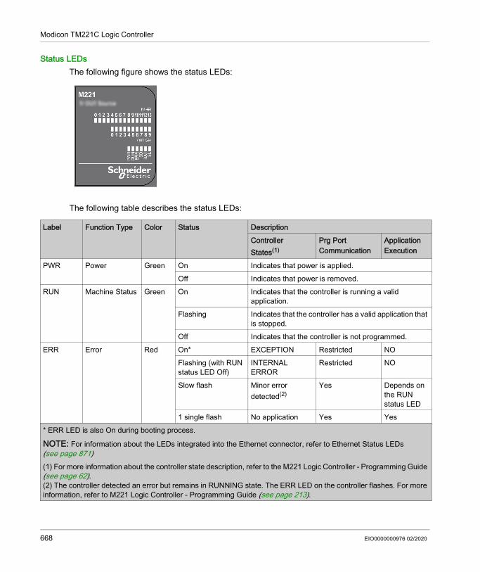
Modicon TM221C Logic Controller
Status LEDsThe following figure shows the status LEDs:
The following table describes the status LEDs:
Label Function Type Color Status DescriptionController States(1)
Prg Port Communication
Application Execution
PWR Power Green On Indicates that power is applied.Off Indicates that power is removed.
RUN Machine Status Green On Indicates that the controller is running a valid application.
Flashing Indicates that the controller has a valid application that is stopped.
Off Indicates that the controller is not programmed.ERR Error Red On* EXCEPTION Restricted NO
Flashing (with RUN status LED Off)
INTERNAL ERROR
Restricted NO
Slow flash Minor error detected(2)
Yes Depends on the RUN status LED
1 single flash No application Yes Yes* ERR LED is also On during booting process.
NOTE: For information about the LEDs integrated into the Ethernet connector, refer to Ethernet Status LEDs (see page 871)(1) For more information about the controller state description, refer to the M221 Logic Controller - Programming Guide (see page 62).(2) The controller detected an error but remains in RUNNING state. The ERR LED on the controller flashes. For more information, refer to M221 Logic Controller - Programming Guide (see page 213).
668 EIO0000000976 02/2020

Modicon TM221C Logic Controller
DimensionsThe following figure shows the external dimensions of the logic controllers:
SD SD Card Access (see page 571)
Green On Indicates that the SD card is being accessed.Flashing Indicates that an error was detected during the SD
card operation.Off Indicates no access (idle) or no card is present.
BAT Battery (see page 553)
Red On Indicates that the battery needs to be replaced.Flashing Indicates that the battery charge is low.Off Indicates that the battery is OK.
SL Serial line 1 (see page 872)
Green On Indicates the status of Serial line 1.Flashing Indicates activity on Serial line 1.Off Indicates no serial communication.
Label Function Type Color Status DescriptionController States(1)
Prg Port Communication
Application Execution
* ERR LED is also On during booting process.
NOTE: For information about the LEDs integrated into the Ethernet connector, refer to Ethernet Status LEDs (see page 871)(1) For more information about the controller state description, refer to the M221 Logic Controller - Programming Guide (see page 62).(2) The controller detected an error but remains in RUNNING state. The ERR LED on the controller flashes. For more information, refer to M221 Logic Controller - Programming Guide (see page 213).
EIO0000000976 02/2020 669

Modicon TM221C Logic Controller
TM221CE24U Presentation
OverviewThe following features are integrated into the TM221CE24U logic controller: 14 digital inputs 4 fast inputs (HSC) 10 regular inputs
10 digital outputs 2 fast sink transistor outputs 8 regular sink transistor outputs
2 analog inputs Communication ports 1 serial line port 1 USB mini-B programming port 1 Ethernet port
670 EIO0000000976 02/2020

Modicon TM221C Logic Controller
DescriptionThe following figure shows the different components of the logic controllers:
N° Description Refer to1 Status LEDs –2 Output removable terminal block Rules for Removable Screw Terminal
Block (see page 604)3 Clip-on lock for 35 mm (1.38 in.) top hat section rail (DIN-rail) DIN Rail (see page 593)4 Ethernet port / RJ45 connector Ethernet port (see page 869)5 24 Vdc power supply Power supply (see page 610)
EIO0000000976 02/2020 671

Modicon TM221C Logic Controller
6 USB mini-B programming port / For terminal connection to a programming PC (EcoStruxure Machine Expert - Basic)
USB mini-B programming port (see page 867)
7 Serial line port 1 / RJ45 connector (RS-232 or RS-485) Serial line 1 (see page 872)8 SD Card slot SD Card Slot (see page 571)9 2 analog inputs Analog Inputs (see page 738)10 Run/Stop switch Run/Stop switch (see page 568)11 Input removable terminal block Rules for Removable Screw Terminal
Block (see page 604)12 I/O expansion connector –13 Cartridge slot –14 Protective cover (SD Card slot, Run/Stop switch and USB mini-
B programming port)–
15 Locking hook –16 Removable analog inputs cover –17 Battery holder Installing and Replacing the Battery
(see page 553)
N° Description Refer to
672 EIO0000000976 02/2020

Modicon TM221C Logic Controller
Status LEDsThe following figure shows the status LEDs:
The following table describes the status LEDs:
Label Function Type Color Status Description
Controller States(1) Prg Port Communication
Application Execution
PWR Power Green On Indicates that power is applied.Off Indicates that power is removed.
RUN Machine Status Green On Indicates that the controller is running a valid application.
Flashing Indicates that the controller has a valid application that is stopped.
Off Indicates that the controller is not programmed.ERR Error Red On* EXCEPTION Restricted NO
Flashing (with RUN status LED Off)
INTERNAL ERROR
Restricted NO
Slow flash Minor error detected(2)
Yes Depends on the RUN status LED
1 single flash No application Yes Yes* ERR LED is also On during booting process.
NOTE: For information about the LEDs integrated into the Ethernet connector, refer to Ethernet Status LEDs (see page 871)(1) For more information about the controller state description, refer to the M221 Logic Controller - Programming Guide (see page 62).(2) The controller detected an error but remains in RUNNING state. The ERR LED on the controller flashes. For more information, refer to M221 Logic Controller - Programming Guide (see page 213).
EIO0000000976 02/2020 673

Modicon TM221C Logic Controller
DimensionsThe following figure shows the external dimensions of the logic controllers:
SD SD Card Access (see page 571)
Green On Indicates that the SD card is being accessed.Flashing Indicates that an error was detected during the SD card
operation.Off Indicates no access (idle) or no card is present.
BAT Battery (see page 553)
Red On Indicates that the battery needs to be replaced.Flashing Indicates that the battery charge is low.Off Indicates that the battery is OK.
SL Serial line 1 (see page 872)
Green On Indicates the status of Serial line 1.Flashing Indicates activity on Serial line 1.Off Indicates no serial communication.
Label Function Type Color Status Description
Controller States(1) Prg Port Communication
Application Execution
* ERR LED is also On during booting process.
NOTE: For information about the LEDs integrated into the Ethernet connector, refer to Ethernet Status LEDs (see page 871)(1) For more information about the controller state description, refer to the M221 Logic Controller - Programming Guide (see page 62).(2) The controller detected an error but remains in RUNNING state. The ERR LED on the controller flashes. For more information, refer to M221 Logic Controller - Programming Guide (see page 213).
674 EIO0000000976 02/2020

Modicon TM221C Logic Controller
TM221C40R Presentation
OverviewThe following features are integrated into theTM221C40R logic controllers: 24 digital inputs 4 fast inputs (HSC) 20 regular inputs
16 digital outputs 16 relay outputs
2 analog inputs Communication ports 1 serial line port 1 USB mini-B programming port
EIO0000000976 02/2020 675

Modicon TM221C Logic Controller
DescriptionThe following figure shows the different components of the logic controllers:
676 EIO0000000976 02/2020

Modicon TM221C Logic Controller
N° Description Refer to1 Status LEDs –2 Output removable terminal block Rules for Removable Screw Terminal
Block (see page 604)3 Clip-on lock for 35 mm (1.38 in.) top hat section rail (DIN-rail) DIN Rail (see page 593)4 100...240 Vac power supply Power supply (see page 616)5 USB mini-B programming port / For terminal connection to a
programming PC (EcoStruxure Machine Expert - Basic)USB mini-B programming port (see page 867)
6 Serial line port 1 / RJ45 connector (RS-232 or RS-485) Serial line 1 (see page 872)7 SD Card slot SD Card Slot (see page 571)8 2 analog inputs Analog Inputs (see page 738)9 Run/Stop switch Run/Stop switch (see page 568)10 Input removable terminal block and embedded power supply
used for connecting sensors to the inputs.(1)Rules for Removable Screw Terminal Block (see page 604)
11 I/O expansion connector –12 Cartridge slot 1 –13 Cartridge slot 2 –14 Protective cover (SD Card slot, Run/Stop switch and USB mini-
B programming port)–
15 Locking hook –16 Removable analog inputs cover –17 Battery holder Installing and Replacing the Battery
(see page 553)(1) Embedded power supply characteristics: Voltage: 24 V -15%...+10% isolated Imax: 250 mA No protection and no overload detection
Refer to Embedded I/O Channels (see page 705).
EIO0000000976 02/2020 677

Modicon TM221C Logic Controller
Status LEDsThe following figure shows the status LEDs:
The following table describes the status LEDs:
Label Function Type Color Status Description
Controller States(1) Prg Port Communication
Application Execution
PWR Power Green On Indicates that power is applied.Off Indicates that power is removed.
RUN Machine Status
Green On Indicates that the controller is running a valid application.
Flashing Indicates that the controller has a valid application that is stopped.
Off Indicates that the controller is not programmed.ERR Error Red On* EXCEPTION Restricted NO
Flashing (with RUN status LED Off)
INTERNAL ERROR
Restricted NO
Slow flash Minor error detected(2)
Yes Depends on the RUN status LED
1 single flash No application Yes Yes* ERR LED is also On during booting process.
NOTE: For information about the LEDs integrated into the Ethernet connector, refer to Ethernet Status LEDs (see page 871)(1) For more information about the controller state description, refer to the M221 Logic Controller - Programming Guide (see page 62).(2) The controller detected an error but remains in RUNNING state. The ERR LED on the controller flashes. For more information, refer to M221 Logic Controller - Programming Guide (see page 213).
678 EIO0000000976 02/2020

Modicon TM221C Logic Controller
DimensionsThe following figure shows the external dimensions of the logic controllers:
SD SD Card Access (see page 571)
Green On Indicates that the SD card is being accessed.Flashing Indicates that an error was detected during the SD card
operation.Off Indicates no access (idle) or no card is present.
BAT Battery (see page 553)
Red On Indicates that the battery needs to be replaced.Flashing Indicates that the battery charge is low.Off Indicates that the battery is OK.
SL Serial line 1 (see page 872)
Green On Indicates the status of Serial line 1.Flashing Indicates activity on Serial line 1.Off Indicates no serial communication.
Label Function Type Color Status Description
Controller States(1) Prg Port Communication
Application Execution
* ERR LED is also On during booting process.
NOTE: For information about the LEDs integrated into the Ethernet connector, refer to Ethernet Status LEDs (see page 871)(1) For more information about the controller state description, refer to the M221 Logic Controller - Programming Guide (see page 62).(2) The controller detected an error but remains in RUNNING state. The ERR LED on the controller flashes. For more information, refer to M221 Logic Controller - Programming Guide (see page 213).
EIO0000000976 02/2020 679

Modicon TM221C Logic Controller
TM221CE40R Presentation
OverviewThe following features are integrated into the TM221CE40R logic controllers: 24 digital inputs 4 fast inputs (HSC) 20 regular inputs
16 digital outputs 16 relay outputs
2 analog inputs Communication ports 1 serial line port 1 USB mini-B programming port 1 Ethernet port
680 EIO0000000976 02/2020

Modicon TM221C Logic Controller
DescriptionThe following figure shows the different components of the logic controllers:
EIO0000000976 02/2020 681

Modicon TM221C Logic Controller
N° Description Refer to1 Status LEDs –2 Output removable terminal block Rules for Removable Screw Terminal
Block (see page 604)3 Clip-on lock for 35 mm (1.38 in.) top hat section rail (DIN-rail) DIN Rail (see page 593)4 Ethernet port / RJ45 connector Ethernet port (see page 869)5 100...240 Vac power supply Power supply (see page 616)6 USB mini-B programming port / For terminal connection to a
programming PC (EcoStruxure Machine Expert - Basic)USB mini-B programming port (see page 867)
7 Serial line port 1 / RJ45 connector (RS-232 or RS-485) Serial line 1 (see page 872)8 SD Card slot SD Card Slot (see page 571)9 2 analog inputs Analog Inputs (see page 738)10 Run/Stop switch Run/Stop switch (see page 568)11 Input removable terminal block and embedded power supply
used for connecting sensors to the inputs.(1)Rules for Removable Screw Terminal Block (see page 604)
12 I/O expansion connector –13 Cartridge slot 1 –14 Cartridge slot 2 –15 Protective cover (SD Card slot, Run/Stop switch and USB mini-
B programming port)–
16 Locking hook –17 Removable analog inputs cover –18 Battery holder Installing and Replacing the Battery
(see page 553)(1) Embedded power supply characteristics: Voltage: 24 V -15%...+10% isolated Imax: 250 mA No protection and no overload detection
Refer to Embedded I/O Channels (see page 705).
682 EIO0000000976 02/2020

Modicon TM221C Logic Controller
Status LEDsThe following figure shows the status LEDs:
The following table describes the status LEDs:
Label Function Type Color Status Description
Controller States(1) Prg Port Communication
Application Execution
PWR Power Green On Indicates that power is applied.Off Indicates that power is removed.
RUN Machine Status Green On Indicates that the controller is running a valid application.
Flashing Indicates that the controller has a valid application that is stopped.
Off Indicates that the controller is not programmed.ERR Error Red On* EXCEPTION Restricted NO
Flashing (with RUN status LED Off)
INTERNAL ERROR
Restricted NO
Slow flash Minor error detected(2)
Yes Depends on the RUN status LED
1 single flash No application Yes Yes* ERR LED is also On during booting process.
NOTE: For information about the LEDs integrated into the Ethernet connector, refer to Ethernet Status LEDs (see page 871)(1) For more information about the controller state description, refer to the M221 Logic Controller - Programming Guide (see page 62).(2) The controller detected an error but remains in RUNNING state. The ERR LED on the controller flashes. For more information, refer to M221 Logic Controller - Programming Guide (see page 213).
EIO0000000976 02/2020 683

Modicon TM221C Logic Controller
DimensionsThe following figure shows the external dimensions of the logic controllers:
SD SD Card Access (see page 571)
Green On Indicates that the SD card is being accessed.Flashing Indicates that an error was detected during the SD card
operation.Off Indicates no access (idle) or no card is present.
BAT Battery (see page 553)
Red On Indicates that the battery needs to be replaced.Flashing Indicates that the battery charge is low.Off Indicates that the battery is OK.
SL Serial line 1 (see page 872)
Green On Indicates the status of Serial line 1.Flashing Indicates activity on Serial line 1.Off Indicates no serial communication.
Label Function Type Color Status Description
Controller States(1) Prg Port Communication
Application Execution
* ERR LED is also On during booting process.
NOTE: For information about the LEDs integrated into the Ethernet connector, refer to Ethernet Status LEDs (see page 871)(1) For more information about the controller state description, refer to the M221 Logic Controller - Programming Guide (see page 62).(2) The controller detected an error but remains in RUNNING state. The ERR LED on the controller flashes. For more information, refer to M221 Logic Controller - Programming Guide (see page 213).
684 EIO0000000976 02/2020

Modicon TM221C Logic Controller
TM221C40T Presentation
OverviewThe following features are integrated into the TM221C40T logic controller: 24 digital inputs 4 fast inputs (HSC) 20 regular inputs
16 digital outputs 2 fast source transistor outputs 14 regular source transistor outputs
2 analog inputs Communication ports 1 serial line port 1 USB mini-B programming port
EIO0000000976 02/2020 685

Modicon TM221C Logic Controller
DescriptionThe following figure shows the different components of the logic controllers:
N° Description Refer to1 Status LEDs –2 Output removable terminal block Rules for Removable Screw Terminal
Block (see page 604)3 Clip-on lock for 35 mm (1.38 in.) top hat section rail (DIN-rail) DIN Rail (see page 593)4 24 Vdc power supply Power supply (see page 610)
686 EIO0000000976 02/2020

Modicon TM221C Logic Controller
5 USB mini-B programming port / For terminal connection to a programming PC (EcoStruxure Machine Expert - Basic)
USB mini-B programming port (see page 867)
6 Serial line port 1 / RJ45 connector (RS-232 or RS-485) Serial line 1 (see page 872)7 SD Card slot SD Card Slot (see page 571)8 2 analog inputs Analog Inputs (see page 738)9 Run/Stop switch Run/Stop switch (see page 568)10 Input removable terminal block Rules for Removable Screw Terminal
Block (see page 604)11 I/O expansion connector –12 Cartridge slot 1 –13 Cartridge slot 2 –14 Protective cover (SD Card slot, Run/Stop switch and USB mini-
B programming port)–
15 Locking hook –16 Removable analog inputs cover –17 Battery holder Installing and Replacing the Battery
(see page 553)
N° Description Refer to
EIO0000000976 02/2020 687

Modicon TM221C Logic Controller
Status LEDsThe following figure shows the status LEDs:
The following table describes the status LEDs:
Label Function Type Color Status DescriptionController States(1)
Prg Port Communication
Application Execution
PWR Power Green On Indicates that power is applied.Off Indicates that power is removed.
RUN Machine Status Green On Indicates that the controller is running a valid application.
Flashing Indicates that the controller has a valid application that is stopped.
Off Indicates that the controller is not programmed.ERR Error Red On* EXCEPTION Restricted NO
Flashing (with RUN status LED Off)
INTERNAL ERROR
Restricted NO
Slow flash Minor error detected(2)
Yes Depends on the RUN status LED
1 single flash No application Yes Yes* ERR LED is also On during booting process.
NOTE: For information about the LEDs integrated into the Ethernet connector, refer to Ethernet Status LEDs (see page 871)(1) For more information about the controller state description, refer to the M221 Logic Controller - Programming Guide (see page 62).(2) The controller detected an error but remains in RUNNING state. The ERR LED on the controller flashes. For more information, refer to M221 Logic Controller - Programming Guide (see page 213).
688 EIO0000000976 02/2020

Modicon TM221C Logic Controller
DimensionsThe following figure shows the external dimensions of the logic controllers:
SD SD Card Access (see page 571)
Green On Indicates that the SD card is being accessed.Flashing Indicates that an error was detected during the SD
card operation.Off Indicates no access (idle) or no card is present.
BAT Battery (see page 553)
Red On Indicates that the battery needs to be replaced.Flashing Indicates that the battery charge is low.Off Indicates that the battery is OK.
SL Serial line 1 (see page 872)
Green On Indicates the status of Serial line 1.Flashing Indicates activity on Serial line 1.Off Indicates no serial communication.
Label Function Type Color Status DescriptionController States(1)
Prg Port Communication
Application Execution
* ERR LED is also On during booting process.
NOTE: For information about the LEDs integrated into the Ethernet connector, refer to Ethernet Status LEDs (see page 871)(1) For more information about the controller state description, refer to the M221 Logic Controller - Programming Guide (see page 62).(2) The controller detected an error but remains in RUNNING state. The ERR LED on the controller flashes. For more information, refer to M221 Logic Controller - Programming Guide (see page 213).
EIO0000000976 02/2020 689

Modicon TM221C Logic Controller
TM221CE40T Presentation
OverviewThe following features are integrated into the TM221CE40T logic controllers: 24 digital inputs 4 fast inputs (HSC) 20 regular inputs
16 digital outputs 2 fast source transistor outputs 14 regular source transistor outputs
2 analog inputs Communication ports 1 serial line port 1 USB mini-B programming port 1 Ethernet port
690 EIO0000000976 02/2020

Modicon TM221C Logic Controller
DescriptionThe following figure shows the different components of the logic controllers:
N° Description Refer to1 Status LEDs –2 Output removable terminal block Rules for Removable Screw Terminal
Block (see page 604)3 Clip-on lock for 35 mm (1.38 in.) top hat section rail (DIN-rail) DIN Rail (see page 593)4 Ethernet port / RJ45 connector Ethernet port (see page 869)5 24 Vdc power supply Power supply (see page 610)
EIO0000000976 02/2020 691

Modicon TM221C Logic Controller
6 USB mini-B programming port / For terminal connection to a programming PC (EcoStruxure Machine Expert - Basic)
USB mini-B programming port (see page 867)
7 Serial line port 1 / RJ45 connector (RS-232 or RS-485) Serial line 1 (see page 872)8 SD Card slot SD Card Slot (see page 571)9 2 analog inputs Analog Inputs (see page 738)10 Run/Stop switch Run/Stop switch (see page 568)11 Input removable terminal block Rules for Removable Screw Terminal
Block (see page 604)12 I/O expansion connector –13 Cartridge slot 1 –14 Cartridge slot 2 –15 Protective cover (SD Card slot, Run/Stop switch and USB mini-
B programming port)–
16 Locking hook –17 Removable analog inputs cover –18 Battery holder Installing and Replacing the Battery
(see page 553)
N° Description Refer to
692 EIO0000000976 02/2020

Modicon TM221C Logic Controller
Status LEDsThe following figure shows the status LEDs:
The following table describes the status LEDs:
Label Function Type Color Status DescriptionController States(1)
Prg Port Communication
Application Execution
PWR Power Green On Indicates that power is applied.Off Indicates that power is removed.
RUN Machine Status Green On Indicates that the controller is running a valid application.
Flashing Indicates that the controller has a valid application that is stopped.
Off Indicates that the controller is not programmed.ERR Error Red On* EXCEPTION Restricted NO
Flashing (with RUN status LED Off)
INTERNAL ERROR
Restricted NO
Slow flash Minor error detected(2)
Yes Depends on the RUN status LED
1 single flash No application Yes Yes* ERR LED is also On during booting process.
NOTE: For information about the LEDs integrated into the Ethernet connector, refer to Ethernet Status LEDs (see page 871)(1) For more information about the controller state description, refer to the M221 Logic Controller - Programming Guide (see page 62).(2) The controller detected an error but remains in RUNNING state. The ERR LED on the controller flashes. For more information, refer to M221 Logic Controller - Programming Guide (see page 213).
EIO0000000976 02/2020 693

Modicon TM221C Logic Controller
DimensionsThe following figure shows the external dimensions of the logic controllers:
SD SD Card Access (see page 571)
Green On Indicates that the SD card is being accessed.Flashing Indicates that an error was detected during the SD
card operation.Off Indicates no access (idle) or no card is present.
BAT Battery (see page 553)
Red On Indicates that the battery needs to be replaced.Flashing Indicates that the battery charge is low.Off Indicates that the battery is OK.
SL Serial line 1 (see page 872)
Green On Indicates the status of Serial line 1.Flashing Indicates activity on Serial line 1.Off Indicates no serial communication.
Label Function Type Color Status DescriptionController States(1)
Prg Port Communication
Application Execution
* ERR LED is also On during booting process.
NOTE: For information about the LEDs integrated into the Ethernet connector, refer to Ethernet Status LEDs (see page 871)(1) For more information about the controller state description, refer to the M221 Logic Controller - Programming Guide (see page 62).(2) The controller detected an error but remains in RUNNING state. The ERR LED on the controller flashes. For more information, refer to M221 Logic Controller - Programming Guide (see page 213).
694 EIO0000000976 02/2020

Modicon TM221C Logic Controller
TM221C40U Presentation
OverviewThe following features are integrated into the TM221C40U logic controller: 24 digital inputs 4 fast inputs (HSC) 20 regular inputs
16 digital outputs 4 fast sink transistor outputs 12 regular sink transistor outputs
2 analog inputs Communication ports 1 serial line port 1 USB mini-B programming port
EIO0000000976 02/2020 695

Modicon TM221C Logic Controller
DescriptionThe following figure shows the different components of the logic controllers:
N° Description Refer to1 Status LEDs –2 Output removable terminal block Rules for Removable Screw Terminal
Block (see page 604)3 Clip-on lock for 35 mm (1.38 in.) top hat section rail (DIN-rail) DIN Rail (see page 593)4 24 Vdc power supply Power supply (see page 610)
696 EIO0000000976 02/2020

Modicon TM221C Logic Controller
5 USB mini-B programming port / For terminal connection to a programming PC (EcoStruxure Machine Expert - Basic)
USB mini-B programming port (see page 867)
6 Serial line port 1 / RJ45 connector (RS-232 or RS-485) Serial line 1 (see page 872)7 SD Card slot SD Card Slot (see page 571)8 2 analog inputs Analog Inputs (see page 738)9 Run/Stop switch Run/Stop switch (see page 568)10 Input removable terminal block Rules for Removable Screw Terminal
Block (see page 604)11 I/O expansion connector –12 Cartridge slot 1 –13 Cartridge slot 2 –14 Protective cover (SD Card slot, Run/Stop switch and USB mini-
B programming port)–
15 Locking hook –16 Removable analog inputs cover –17 Battery holder Installing and Replacing the Battery
(see page 553)
N° Description Refer to
EIO0000000976 02/2020 697

Modicon TM221C Logic Controller
Status LEDsThe following figure shows the status LEDs:
The following table describes the status LEDs:
Label Function Type Color Status DescriptionController States(1)
Prg Port Communication
Application Execution
PWR Power Green On Indicates that power is applied.Off Indicates that power is removed.
RUN Machine Status Green On Indicates that the controller is running a valid application.
Flashing Indicates that the controller has a valid application that is stopped.
Off Indicates that the controller is not programmed.ERR Error Red On* EXCEPTION Restricted NO
Flashing (with RUN status LED Off)
INTERNAL ERROR
Restricted NO
Slow flash Minor error detected(2)
Yes Depends on the RUN status LED
1 single flash No application Yes Yes* ERR LED is also On during booting process.
NOTE: For information about the LEDs integrated into the Ethernet connector, refer to Ethernet Status LEDs (see page 871)(1) For more information about the controller state description, refer to the M221 Logic Controller - Programming Guide (see page 62).(2) The controller detected an error but remains in RUNNING state. The ERR LED on the controller flashes. For more information, refer to M221 Logic Controller - Programming Guide (see page 213).
698 EIO0000000976 02/2020

Modicon TM221C Logic Controller
DimensionsThe following figure shows the external dimensions of the logic controllers:
SD SD Card Access (see page 571)
Green On Indicates that the SD card is being accessed.Flashing Indicates that an error was detected during the SD
card operation.Off Indicates no access (idle) or no card is present.
BAT Battery (see page 553)
Red On Indicates that the battery needs to be replaced.Flashing Indicates that the battery charge is low.Off Indicates that the battery is OK.
SL Serial line 1 (see page 872)
Green On Indicates the status of Serial line 1.Flashing Indicates activity on Serial line 1.Off Indicates no serial communication.
Label Function Type Color Status DescriptionController States(1)
Prg Port Communication
Application Execution
* ERR LED is also On during booting process.
NOTE: For information about the LEDs integrated into the Ethernet connector, refer to Ethernet Status LEDs (see page 871)(1) For more information about the controller state description, refer to the M221 Logic Controller - Programming Guide (see page 62).(2) The controller detected an error but remains in RUNNING state. The ERR LED on the controller flashes. For more information, refer to M221 Logic Controller - Programming Guide (see page 213).
EIO0000000976 02/2020 699

Modicon TM221C Logic Controller
TM221CE40U Presentation
OverviewThe following features are integrated into the TM221CE40U logic controller: 24 digital inputs 4 fast inputs (HSC) 20 regular inputs
16 digital outputs 4 fast sink transistor outputs 12 regular sink transistor outputs
2 analog inputs Communication ports 1 serial line port 1 USB mini-B programming port 1 Ethernet port
700 EIO0000000976 02/2020

Modicon TM221C Logic Controller
DescriptionThe following figure shows the different components of the logic controllers:
N° Description Refer to1 Status LEDs –2 Output removable terminal block Rules for Removable Screw Terminal
Block (see page 604)3 Clip-on lock for 35 mm (1.38 in.) top hat section rail (DIN-rail) DIN Rail (see page 593)4 Ethernet port / RJ45 connector Ethernet port (see page 869)5 24 Vdc power supply Power supply (see page 610)
EIO0000000976 02/2020 701

Modicon TM221C Logic Controller
6 USB mini-B programming port / For terminal connection to a programming PC (EcoStruxure Machine Expert - Basic)
USB mini-B programming port (see page 867)
7 Serial line port 1 / RJ45 connector (RS-232 or RS-485) Serial line 1 (see page 872)8 SD Card slot SD Card Slot (see page 571)9 2 analog inputs Analog Inputs (see page 738)10 Run/Stop switch Run/Stop switch (see page 568)11 Input removable terminal block Rules for Removable Screw Terminal
Block (see page 604)12 I/O expansion connector –13 Cartridge slot 1 –14 Cartridge slot 2 –15 Protective cover (SD Card slot, Run/Stop switch and USB mini-
B programming port)–
16 Locking hook –17 Removable analog inputs cover –18 Battery holder Installing and Replacing the Battery
(see page 553)
N° Description Refer to
702 EIO0000000976 02/2020

Modicon TM221C Logic Controller
Status LEDsThe following figure shows the status LEDs:
The following table describes the status LEDs:
Label Function Type Color Status DescriptionController States(1)
Prg Port Communication
Application Execution
PWR Power Green On Indicates that power is applied.Off Indicates that power is removed.
RUN Machine Status Green On Indicates that the controller is running a valid application.
Flashing Indicates that the controller has a valid application that is stopped.
Off Indicates that the controller is not programmed.ERR Error Red On* EXCEPTION Restricted NO
Flashing (with RUN status LED Off)
INTERNAL ERROR
Restricted NO
Slow flash Minor error detected(2)
Yes Depends on the RUN status LED
1 single flash No application Yes Yes* ERR LED is also On during booting process.
NOTE: For information about the LEDs integrated into the Ethernet connector, refer to Ethernet Status LEDs (see page 871)(1) For more information about the controller state description, refer to the M221 Logic Controller - Programming Guide (see page 62).(2) The controller detected an error but remains in RUNNING state. The ERR LED on the controller flashes. For more information, refer to M221 Logic Controller - Programming Guide (see page 213).
EIO0000000976 02/2020 703

Modicon TM221C Logic Controller
DimensionsThe following figure shows the external dimensions of the logic controllers:
SD SD Card Access (see page 571)
Green On Indicates that the SD card is being accessed.Flashing Indicates that an error was detected during the SD
card operation.Off Indicates no access (idle) or no card is present.
BAT Battery (see page 553)
Red On Indicates that the battery needs to be replaced.Flashing Indicates that the battery charge is low.Off Indicates that the battery is OK.
SL Serial line 1 (see page 872)
Green On Indicates the status of Serial line 1.Flashing Indicates activity on Serial line 1.Off Indicates no serial communication.
Label Function Type Color Status DescriptionController States(1)
Prg Port Communication
Application Execution
* ERR LED is also On during booting process.
NOTE: For information about the LEDs integrated into the Ethernet connector, refer to Ethernet Status LEDs (see page 871)(1) For more information about the controller state description, refer to the M221 Logic Controller - Programming Guide (see page 62).(2) The controller detected an error but remains in RUNNING state. The ERR LED on the controller flashes. For more information, refer to M221 Logic Controller - Programming Guide (see page 213).
704 EIO0000000976 02/2020

Modicon TM221C Logic Controller
Embedded I/O Channels
Section 10.2Embedded I/O Channels
OverviewThis chapter describes the embedded I/O channels.
What Is in This Section?This section contains the following topics:
Topic PageDigital Inputs 706Relay Outputs 721Regular and Fast Transistor Outputs 728Analog Inputs 738
EIO0000000976 02/2020 705

Modicon TM221C Logic Controller
Digital Inputs
OverviewThe Modicon TM221C Logic Controller has digital inputs embedded:
For more information, refer to Input Management (see page 560).
Reference Total number of digital inputs
Fast inputs which can be used as 100 kHz HSC inputs
Regular inputs
TM221C16•TM221CE16•
9 4 5
TM221C24•TM221CE24•
14 4 10
TM221C40•TM221CE40•
24 4 20
DANGERFIRE HAZARD Use only the correct wire sizes for the current capacity of the I/O channels and power supplies. For relay output (2 A) wiring, use conductors of at least 0.5 mm2 (AWG 20) with a temperature
rating of at least 80 °C (176 °F). For common conductors of relay output wiring (7 A), or relay output wiring greater than 2 A,
use conductors of at least 1.0 mm2 (AWG 16) with a temperature rating of at least 80 °C (176 °F).
Failure to follow these instructions will result in death or serious injury.
WARNINGUNINTENDED EQUIPMENT OPERATIONDo not exceed any of the rated values specified in the environmental and electrical characteristics tables.Failure to follow these instructions can result in death, serious injury, or equipment damage.
706 EIO0000000976 02/2020

Modicon TM221C Logic Controller
Regular Input CharacteristicsThe following table describes the characteristics of the TM221C Logic Controller regular inputs:
Characteristic ValueTM221C16•TM221CE16•
TM221C24•TM221CE24•
TM221C40•TM221CE40•
Number of regular inputs 5 inputs (I2, I3, I4, I5, I8)
10 inputs (I2...I5, I8...I13)
20 inputs (I2...I5, I8...I23)
Number of channel groups 1 common line for I0...I8
1 common line for I0...I13
1 common line for I0....I23
Input type Type 1 (IEC/EN 61131-2)Logic type Sink/SourceInput voltage range 24 VdcRated input voltage 19.2...28.8 VdcRated input current 7 mAInput impedance 3.4 kΩInput limit values Voltage at state 1 > 15 Vdc (15...28.8 Vdc)
Voltage at state 0 < 5 Vdc (0...5 Vdc)Current at state 1 > 2.5 mACurrent at state 0 < 1.0 mA
Derating See derating curves (see page 709)Turn on time I2, I3, I4, I5 35 µs + filter value1
I8...I23 100 µs + filter value1
Turn off time I2, I3, I4, I5 35 µs + filter value1
I8...I23 100 µs + filter value1
Isolation Between input and internal logic
500 Vac
Connection type Removable screw terminal blocksConnector insertion/removal durability Over 100 timesCable Type Unshielded
Length Maximum 30 m (98 ft)1 For more information, refer to Integrator Filter Principle (see page 560)
EIO0000000976 02/2020 707

Modicon TM221C Logic Controller
Fast Input CharacteristicsThe following table describes the characteristics of the TM221C Logic Controller fast inputs:
Characteristic ValueNumber of fast inputs 4 inputs (I0, I1, I6, I7)Number of channel groups 1 common lineInput type Type 1 (IEC/EN 61131-2)Logic type Sink/SourceRated input voltage 24 VdcInput voltage range 19.2...28.8 VdcRated input current 5 mAInput impedance 4.9 kΩInput limit values Voltage at state 1 > 15 Vdc (15...28.8 Vdc)
Voltage at state 0 < 5 Vdc (0...5 Vdc)Current at state 1 > 2.6 mACurrent at state 0 < 0.6 mA
Derating See derating curves (see page 709)Turn on time 5 µs + filter value1
Turn off time 5 µs + filter value1
HSC maximum frequency Dual Phase 100 kHzSingle phase 100 kHz Frequency Meter 100 kHz
Supported HSC operation mode Dual Phase [Pulse / Direction] Dual Phase [Quadrature X1] Dual Phase [Quadrature X2] Dual Phase [Quadrature X4] Single Phase Frequency Meter
Isolation Between input and internal logic
500 Vac
Between channel groups
500 Vac
Connection type Removable screw terminal blockConnector insertion/removal durability Over 100 timesCable Type Shielded, including the 24 Vdc power supply
Length Maximum 10 m (32.8 ft)1 For more information, refer to Integrator Filter Principle (see page 560)
708 EIO0000000976 02/2020

Modicon TM221C Logic Controller
Derating Curves (No Cartridge)The following figures show the derating curves of the embedded digital inputs for a configuration without cartridge:
X Input simultaneous ON ratioY Input voltage
X Ambient temperatureY Input simultaneous ON ratio
EIO0000000976 02/2020 709

Modicon TM221C Logic Controller
Derating Curves (with Cartridge)The following figures show the derating curves of the embedded digital inputs for a configuration with cartridge:
X Input simultaneous ON ratioY Input voltage
X Ambient temperatureY Input simultaneous ON ratio
710 EIO0000000976 02/2020

Modicon TM221C Logic Controller
TM221C16R / TM221CE16R Wiring DiagramsThe following figure presents the sink wiring diagram (positive logic) of the inputs to the sensors for TM221C16R and TM221CE16R:
* Type T fuse
The following figure presents the source wiring diagram (negative logic) of the inputs to the sensors for TM221C16R and TM221CE16R:
* Type T fuse
NOTE: The TM221C Logic Controller provides a 24 Vdc supply to the inputs.The following figure presents the connection of the fast inputs:
Ix I0, I1, I6, I7
TM221C24R / TM221CE24R Wiring DiagramsThe following figure presents the sink wiring diagram (positive logic) of the inputs to the sensors for TM221C24R and TM221CE24R:
* Type T fuse
EIO0000000976 02/2020 711

Modicon TM221C Logic Controller
The following figure presents the source wiring diagram (negative logic) of the inputs to the sensors for TM221C24R and TM221CE24R:
* Type T fuse
NOTE: The TM221C Logic Controller provides a 24 Vdc supply to the inputs.The following figure presents the connection of the fast inputs:
Ix I0, I1, I6, I7
TM221C40R / TM221CE40R Wiring DiagramsThe following figure presents the sink wiring diagram (positive logic) of the inputs to the sensors for TM221C40R and TM221CE40R:
* Type T fuse
The following figure presents the source wiring diagram (negative logic) of the inputs to the sensors for TM221C40R and TM221CE40R:
* Type T fuse
NOTE: The TM221C Logic Controller provides a 24 Vdc supply to the inputs.
712 EIO0000000976 02/2020

Modicon TM221C Logic Controller
The following figure presents the connection of the fast inputs:
Ix I0, I1, I6, I7
TM221C••R / TM221CE••R Encoder Examples Wiring Diagrams The following figures show four wiring examples for TM221C••R and TM221CE••R: dual-phase encoder without index dual-phase encoder with a limit switch and no index dual-phase encoder with index dual-phase encoder with index and PNP sensorTM221C••R / TM221CE••R with a dual-phase encoder without index:
(1) Dual phase encoder without index
TM221C••R / TM221CE••R with a dual-phase encoder with a limit switch and no index:
(1) Dual phase encoder without index(2) Limit switch
EIO0000000976 02/2020 713

Modicon TM221C Logic Controller
TM221C••R / TM221CE••R with a dual-phase encoder with index:
(1) Dual phase encoder with index
TM221C••R / TM221CE••R with a dual-phase encoder with index and PNP sensor:
(1) Dual phase encoder with index(2) PNP sensor
TM221C16T / TM221CE16T Wiring DiagramsThe following figure presents the connection of the inputs to the sensors for TM221C16T and TM221CE16T:
* Type T fuseA Sink wiring (positive logic).B Source wiring (negative logic).
714 EIO0000000976 02/2020

Modicon TM221C Logic Controller
The following figure presents the connection of the fast inputs:
Ix I0, I1, I6, I7
TM221C24T / TM221CE24T Wiring DiagramsThe following figure presents the connection of the inputs to the sensors for TM221C24T and TM221CE24T:
* Type T fuseA Sink wiring (positive logic).B Source wiring (negative logic).
The following figure presents the connection of the fast inputs:
Ix I0, I1, I6, I7
WARNINGUNINTENDED EQUIPMENT OPERATIONDo not connect wires to unused terminals and/or terminals indicated as “No Connection (N.C.)”.Failure to follow these instructions can result in death, serious injury, or equipment damage.
EIO0000000976 02/2020 715

Modicon TM221C Logic Controller
TM221C40T / TM221CE40T Wiring DiagramsThe following figure presents the connection of the inputs to the sensors for TM221C40T and TM221CE40T:
* Type T fuseA Sink wiring (positive logic).B Source wiring (negative logic).
The following figure presents the connection of the fast inputs:
Ix I0, I1, I6, I7
TM221C••T / TM221CE••T Encoder Examples Wiring DiagramsThe following figures show four wiring examples for TM221C••T and TM221CE••T: dual-phase encoder without index dual-phase encoder with a limit switch and no index dual-phase encoder with index dual-phase encoder with index and PNP sensor
WARNINGUNINTENDED EQUIPMENT OPERATIONDo not connect wires to unused terminals and/or terminals indicated as “No Connection (N.C.)”.Failure to follow these instructions can result in death, serious injury, or equipment damage.
WARNINGUNINTENDED EQUIPMENT OPERATIONDo not connect wires to unused terminals and/or terminals indicated as “No Connection (N.C.)”.Failure to follow these instructions can result in death, serious injury, or equipment damage.
716 EIO0000000976 02/2020

Modicon TM221C Logic Controller
TM221C••T / TM221CE••T with a dual-phase encoder without index:
(1) Dual phase encoder without index
TM221C••T / TM221CE••T with a dual-phase encoder with a limit switch and no index:
(1) Dual phase encoder without index(2) Limit switch
TM221C••T / TM221CE••T with a dual-phase encoder with index:
(1) Dual phase encoder with index
EIO0000000976 02/2020 717

Modicon TM221C Logic Controller
TM221C••T / TM221CE••T with a dual-phase encoder with index and PNP sensor:
(1) Dual phase encoder with index(2) PNP sensor
TM221C16U / TM221CE16U Wiring DiagramsThe following figure presents the connection of the inputs to the sensors for TM221C16U and TM221CE16U:
* Type T fuseA Sink wiring (positive logic).B Source wiring (negative logic).
The following figure presents the connection of the fast inputs:
Ix I0, I1, I6, I7
WARNINGUNINTENDED EQUIPMENT OPERATIONDo not connect wires to unused terminals and/or terminals indicated as “No Connection (N.C.)”.Failure to follow these instructions can result in death, serious injury, or equipment damage.
718 EIO0000000976 02/2020

Modicon TM221C Logic Controller
TM221C24U / TM221CE24U Wiring DiagramsThe following figure presents the connection of the inputs to the sensors for TM221C24U and TM221CE24U:
* Type T fuseA Sink wiring (positive logic).B Source wiring (negative logic).
The following figure presents the connection of the fast inputs:
Ix I0, I1, I6, I7
WARNINGUNINTENDED EQUIPMENT OPERATIONDo not connect wires to unused terminals and/or terminals indicated as “No Connection (N.C.)”.Failure to follow these instructions can result in death, serious injury, or equipment damage.
WARNINGUNINTENDED EQUIPMENT OPERATIONDo not connect wires to unused terminals and/or terminals indicated as “No Connection (N.C.)”.Failure to follow these instructions can result in death, serious injury, or equipment damage.
EIO0000000976 02/2020 719

Modicon TM221C Logic Controller
TM221C40U / TM221CE40U Wiring DiagramsThe following figure presents the connection of the inputs to the sensors for TM221C40U and TM221CE40U:
* Type T fuseA Sink wiring (positive logic).B Source wiring (negative logic).
The following figure presents the connection of the fast inputs:
Ix I0, I1, I6, I7
WARNINGUNINTENDED EQUIPMENT OPERATIONDo not connect wires to unused terminals and/or terminals indicated as “No Connection (N.C.)”.Failure to follow these instructions can result in death, serious injury, or equipment damage.
720 EIO0000000976 02/2020

Modicon TM221C Logic Controller
Relay Outputs
Overview The Modicon TM221C Logic Controller has 7, 10 or 16 relay outputs embedded:
For more information, refer to Output Management (see page 564).
Reference Number of relay outputsTM221C16R / TM221CE16R 7TM221C24R / TM221CE24R 10TM221C40R / TM221CE40R 16
DANGERFIRE HAZARD Use only the correct wire sizes for the current capacity of the I/O channels and power supplies. For relay output (2 A) wiring, use conductors of at least 0.5 mm2 (AWG 20) with a temperature
rating of at least 80 °C (176 °F). For common conductors of relay output wiring (7 A), or relay output wiring greater than 2 A,
use conductors of at least 1.0 mm2 (AWG 16) with a temperature rating of at least 80 °C (176 °F).
Failure to follow these instructions will result in death or serious injury.
WARNINGUNINTENDED EQUIPMENT OPERATIONDo not exceed any of the rated values specified in the environmental and electrical characteristics tables.Failure to follow these instructions can result in death, serious injury, or equipment damage.
EIO0000000976 02/2020 721

Modicon TM221C Logic Controller
Relay Output CharacteristicsThe following table describes the characteristics of the TM221C Logic Controller with relay outputs:
Characteristic ValueTM221C16R / TM221CE16R
TM221C24R / TM221CE24R
TM221C40R / TM221CE40R
Number of relay outputs 7 outputs 10 outputs 16 outputsNumber of channel groups 1 common line for
Q0...Q31 common line for Q4...Q6
1 common line for Q0...Q31 common line for Q4...Q71 common line for Q8, Q9
1 common line for Q0...Q31 common line for Q4...Q71 common line for Q8...Q111 common line for Q12...Q15
Output type RelayContact type NO (Normally Open)Rated output voltage 24 Vdc, 240 VacMaximum voltage at 2 A 30 Vdc, 264 VacMinimum switching load 5 Vdc at 10 mARated output current 2 AMaximum output current 2 A per output
7 A for common 0 (Q0...Q3)6 A for common 1 (Q4...Q6)
7 A for common 0 (Q0...Q3)7 A for common 1 (Q4...Q7)4 A for common 2 (Q8, Q9)
7 A per common
Maximum output frequency with maximum load
20 operations per minute
Derating No deratingTurn on time Max. 10 msTurn off time Max. 10 msContact resistance 30 mΩ maxMechanical life 20 million operationsElectrical life
Under resistive load See power limitation (see page 723)Under inductive load
Protection against short circuit No
722 EIO0000000976 02/2020

Modicon TM221C Logic Controller
Power LimitationThe following table describes the power limitation of the relay outputs depending on the voltage, the type of load, and the number of operations required.These controllers do not support capacitive loads.
Isolation Between output and internal logic
500 Vac
Between channel groups
500 Vac
Connection type Removable screw terminal blocksConnector insertion/removal durability
Over 100 times
Cable Type UnshieldedLength Max. 30 m (98 ft)
NOTE: Refer to Protecting Outputs from Inductive Load Damage (see page 607) for additional information concerning output protection.
Characteristic ValueTM221C16R / TM221CE16R
TM221C24R / TM221CE24R
TM221C40R / TM221CE40R
WARNINGRELAY OUTPUTS WELDED CLOSED Always protect relay outputs from inductive alternating current load damage using an
appropriate external protective circuit or device. Do not connect relay outputs to capacitive loads.Failure to follow these instructions can result in death, serious injury, or equipment damage.
Power LimitationsVoltage 24 Vdc 120 Vac 240 Vac Number of
operationsPower of resistive loadsAC-12
– 240 VA80 VA
480 VA160 VA
100,000300,000
Power of inductive loadsAC-15 (cos ϕ = 0.35)
– 60 VA18 VA
120 VA36 VA
100,000300,000
Power of inductive loadsAC-14 (cos ϕ = 0.7)
– 120 VA36 VA
240 VA72 VA
100,000300,000
EIO0000000976 02/2020 723

Modicon TM221C Logic Controller
Relay Outputs Wiring Diagrams - Negative Logic (Sink)The following figure presents the sink wiring diagram (negative logic) of the outputs to the load for the TM221C16R / TM221CE16R:
* Type T fuse(1) The COM1 and COM2 terminals are not connected internally.(2) To improve the life time of the contacts, and to protect from potential inductive load damage, you must
connect a free wheeling diode in parallel to each inductive DC load or an RC snubber in parallel of each inductive AC load
B Sink wiring (negative logic)
The following figure presents the sink wiring diagram (negative logic) of the outputs to the load for the TM221C24R / TM221CE24R:
* Type T fuse(1) The COM0, COM1 and COM2 terminals are not connected internally.(2) To improve the life time of the contacts, and to protect from potential inductive load damage, you must
connect a free wheeling diode in parallel to each inductive DC load or an RC snubber in parallel of each inductive AC load
B Sink wiring (negative logic)
Power of resistive loadsDC-12
48 W16 W
– – 100,000300,000
Power of inductive loadsDC-13 L/R = 7 ms
24 W7.2 W
– – 100,000300,000
Power Limitations
724 EIO0000000976 02/2020

Modicon TM221C Logic Controller
The following figure presents the sink wiring diagram (negative logic) of the outputs to the load for the TM221C40R / TM221CE40R:
* Type T fuse(1) The COM0, COM1, COM2 and COM3 terminals are not connected internally.(2) To improve the life time of the contacts, and to protect from potential inductive load damage, you must
connect a free wheeling diode in parallel to each inductive DC load or an RC snubber in parallel of each inductive AC load
B Sink wiring (negative logic)
NOTE: The assigned fuse values have been specified for the maximum current characteristics of the controller I/O and associated commons. You may have other considerations that are applicable based on the unique types of input and output devices you connect, and you should size your fuses accordingly.
EIO0000000976 02/2020 725

Modicon TM221C Logic Controller
Relay Outputs Wiring Diagrams - Positive Logic (Source)The following figure presents the source wiring diagram (positive logic) of the outputs to the load for the TM221C16R / TM221CE16R:
* Type T fuse(1) The COM1 and COM2 terminals are not connected internally.(2) To improve the life time of the contacts, and to protect from potential inductive load damage, you must
connect a free wheeling diode in parallel to each inductive DC load or an RC snubber in parallel of each inductive AC load
A Source wiring (positive logic)
The following figure presents the source wiring diagram (positive logic) of the outputs to the load for the TM221C24R / TM221CE24R:
* Type T fuse(1) The COM0, COM1 and COM2 terminals are not connected internally.(2) To improve the life time of the contacts, and to protect from potential inductive load damage, you must
connect a free wheeling diode in parallel to each inductive DC load or an RC snubber in parallel of each inductive AC load
A Source wiring (positive logic)
726 EIO0000000976 02/2020

Modicon TM221C Logic Controller
The following figure presents the source wiring diagram (positive logic) of the outputs to the load for the TM221C40R / TM221CE40R:
* Type T fuse(1) The COM0, COM1, COM2 and COM3 terminals are not connected internally.(2) To improve the life time of the contacts, and to protect from potential inductive load damage, you must
connect a free wheeling diode in parallel to each inductive DC load or an RC snubber in parallel of each inductive AC load
A Source wiring (positive logic)
NOTE: The assigned fuse values have been specified for the maximum current characteristics of the controller I/O and associated commons. You may have other considerations that are applicable based on the unique types of input and output devices you connect, and you should size your fuses accordingly.
EIO0000000976 02/2020 727

Modicon TM221C Logic Controller
Regular and Fast Transistor Outputs
OverviewThe Modicon TM221C Logic Controller has regular and fast transistor outputs embedded:
For more information, refer to Output Management (see page 564).
Reference Total number of digital outputs
Transistor outputs Fast outputs
TM221C16T / TM221CE16T 7 5 2TM221C16U / TM221CE16U 7 5 2TM221C24T / TM221CE24T 10 8 2TM221C24U / TM221CE24U 10 8 2TM221C40T / TM221CE40T 16 14 2TM221C40U / TM221CE40U 16 12 4
DANGERFIRE HAZARD Use only the correct wire sizes for the current capacity of the I/O channels and power supplies. For relay output (2 A) wiring, use conductors of at least 0.5 mm2 (AWG 20) with a temperature
rating of at least 80 °C (176 °F). For common conductors of relay output wiring (7 A), or relay output wiring greater than 2 A,
use conductors of at least 1.0 mm2 (AWG 16) with a temperature rating of at least 80 °C (176 °F).
Failure to follow these instructions will result in death or serious injury.
WARNINGUNINTENDED EQUIPMENT OPERATIONDo not exceed any of the rated values specified in the environmental and electrical characteristics tables.Failure to follow these instructions can result in death, serious injury, or equipment damage.
728 EIO0000000976 02/2020

Modicon TM221C Logic Controller
Regular Transistor Output CharacteristicsThe following table describes the characteristics of the TM221C Logic Controller regular transistor outputs:
Characteristic ValueTM221C16T / TM221CE16T / TM221C16U / TM221CE16U
TM221C24T / TM221CE24T / TM221C24U / TM221CE24U
TM221C40T / TM221CE40T / TM221C40U / TM221CE40U
Number of regular transistor outputs
5 outputs (Q2...Q6) 8 outputs (Q2...Q9) 14 outputs (Q2...Q15) (TM221C40T / TM221CE40T)12 outputs (Q4...Q15) (TM221C40U / TM221CE40U)
Number of channel groups 1 common line for Q0...Q6 1 common line for Q0...Q9 1 common line for Q0...Q71 common line for Q8...Q15
Output type TransistorLogic type Source for TM221•••T
Sink for TM221•••URated output voltage 24 VdcOutput voltage range 19.2...28.8 VdcRated output current 0.5 ATotal output current 3.5 A for channel group
Q0...Q65 A for channel group Q0...Q9
4 A for channel group Q0...Q74 A for channel group Q8...Q15
Voltage drop 1 Vdc maxLeakage current when switched off 0.1 mAMaximum power of filament lamp 12 W maxDerating See derating curves (see page 732)Turn on time
Q2, Q3 Max. 50 µsOther regular outputs Max. 300 µs
Turn off time
Q2, Q3 Max. 50 µsOther regular outputs Max. 300 µs
Protection against short circuit Yes (TM221C•••T only)Short circuit output peak current 1.3 AAutomatic rearming after short circuit or overload
Yes, every 1 s
EIO0000000976 02/2020 729

Modicon TM221C Logic Controller
Fast Transistor Output CharacteristicsThe following table describes the characteristics of the TM221C Logic Controller fast transistor outputs:
Clamping voltage Max. 39 Vdc ± 1 VdcSwitching frequency
Under resistive load 100 Hz max.
Isolation Between output and internal logic
500 Vac
Connection type Removable screw terminal blocksConnector insertion/removal durability
Over 100 times
Cable Type UnshieldedLength Max 30 m (98 ft)
NOTE: Refer to Protecting Outputs from Inductive Load Damage (see page 607) for additional information concerning output protection.
Characteristic ValueTM221C16T / TM221CE16T / TM221C16U / TM221CE16U
TM221C24T / TM221CE24T / TM221C24U / TM221CE24U
TM221C40T / TM221CE40T / TM221C40U / TM221CE40U
Characteristic ValueNumber of fast transistor outputs 2 fast outputs (Q0, Q1)
4 fast outputs (Q0, Q1, Q2 and Q3) for TM221•••40U
Number of channel groups 1 common lineOutput type TransistorLogic type Source for TM221•••T
Sink for TM221•••URated output voltage 24 VdcOutput voltage range 19.2...28.8 VdcRated output current 0.5 ATotal output current TM221C16T / TM221CE16T
TM221C16U / TM221CE16U3.5 A for channel group Q0...Q6
TM221C24T / TM221CE24TTM221C24U / TM221CE24U
5 A for channel group Q0...Q9
TM221C40T / TM221CE40TTM221C40U / TM221CE40U
4 A for channel group Q0...Q74 A for channel group Q8...Q15
Maximum power of filament lamp 12 W max
730 EIO0000000976 02/2020

Modicon TM221C Logic Controller
Derating See derating curves (see page 732)Turn on time (10 mA < output current < 100 mA) Max. 5 µsTurn off time (10 mA < output current < 100 mA) Max. 5 µsProtection against short circuit Yes (TM221C•••T only)Short circuit output peak current 1.3 A max.Automatic rearming after short circuit or overload Yes, every 1 sProtection against reverse polarity YesClamping voltage Typ. 39 Vdc +/- 1 VdcMaximum output frequency
PLS/PWM/PTO/FREQGEN 100 kHz
Isolation Between output and internal logic 500 VacConnection type Removable screw terminal blocksConnector insertion/removal durability Over 100 timesCable Type Shielded, including 24 Vdc power
supplyLength Maximum 3 m (9.84 ft)
NOTE: Refer to Protecting Outputs from Inductive Load Damage (see page 607) for additional information concerning output protection.
Characteristic Value
EIO0000000976 02/2020 731

Modicon TM221C Logic Controller
Derating Curves (No Cartridge)The following figures show the derating curves of the embedded digital outputs for a configuration without cartridge:
X Output simultaneous ON ratioY Output voltage
X Ambient temperatureY Output simultaneous ON ratio
732 EIO0000000976 02/2020

Modicon TM221C Logic Controller
Derating Curves (with Cartridge)The following figures show the derating curves of the embedded digital outputs for a configuration with cartridge:
X Output simultaneous ON ratioY Output voltage
X Ambient temperatureY Output simultaneous ON ratio
EIO0000000976 02/2020 733

Modicon TM221C Logic Controller
Transistor Outputs Wiring Diagrams The following figure presents the connection of the outputs to the load for the TM221C16T / TM221CE16T:
* Type T fuse
The following figure presents the connection of the fast outputs:
Qx Q0, Q1
The following figure presents the connection of the outputs to the load for the TM221C24T / TM221CE24T:
* Type T fuse(1) The V+ terminals are connected internally.
The following figure presents the connection of the fast outputs:
Qx Q0, Q1
734 EIO0000000976 02/2020

Modicon TM221C Logic Controller
The following figure presents the connection of the outputs to the load for the TM221C40T / TM221CE40T:
* Type T fuse(1) The V0+ and V1+ terminals are not connected internally.(2) The V0- and V1- terminals are not connected internally.
The following figure presents the connection of the fast outputs:
Qx Q0, Q1
Sink Transistor Outputs Wiring Diagrams The following figure presents the connection of the outputs to the load for the TM221C16U / TM221CE16U:
* Type T fuse
EIO0000000976 02/2020 735

Modicon TM221C Logic Controller
The following figure presents the connection of the fast outputs:
Qx Q0, Q1
The following figure presents the connection of the outputs to the load for the TM221C24U / TM221CE24U:
* Type T fuse(1) The V- terminals are connected internally.
The following figure presents the connection of the fast outputs:
Qx Q0, Q1
736 EIO0000000976 02/2020
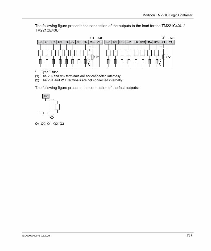
Modicon TM221C Logic Controller
The following figure presents the connection of the outputs to the load for the TM221C40U / TM221CE40U:
* Type T fuse(1) The V0- and V1- terminals are not connected internally.(2) The V0+ and V1+ terminals are not connected internally.
The following figure presents the connection of the fast outputs:
Qx Q0, Q1, Q2, Q3
EIO0000000976 02/2020 737

Modicon TM221C Logic Controller
Analog Inputs
OverviewThe Modicon M221 Logic Controller has 2 analog inputs embedded.
DANGERFIRE HAZARD Use only the correct wire sizes for the current capacity of the I/O channels and power supplies. For relay output (2 A) wiring, use conductors of at least 0.5 mm2 (AWG 20) with a temperature
rating of at least 80 °C (176 °F). For common conductors of relay output wiring (7 A), or relay output wiring greater than 2 A,
use conductors of at least 1.0 mm2 (AWG 16) with a temperature rating of at least 80 °C (176 °F).
Failure to follow these instructions will result in death or serious injury.
WARNINGUNINTENDED EQUIPMENT OPERATIONDo not exceed any of the rated values specified in the environmental and electrical characteristics tables.Failure to follow these instructions can result in death, serious injury, or equipment damage.
738 EIO0000000976 02/2020

Modicon TM221C Logic Controller
Mounting the Analog CablesThe following procedure describes how to mount the analog cables:
Step Action1 Use a screw-driver to remove the protective cover.
2 Push until you hear it “click”.
3 Replace the protective cover.
EIO0000000976 02/2020 739

Modicon TM221C Logic Controller
Analog Input CharacteristicsThe following table describes the characteristics of the M221 Logic Controller with analog inputs:
Characteristic Voltage InputNumber of maximum inputs 2 inputsInput type Single-endedRated input range 0...+10 VdcDigital resolution 10 bitsInput value of LSB 10 mVInput impedance 100 kΩ Input delay time 12 msSample duration time 1 ms per channel + 1 scan timeAccuracy ± 1 % of the full scaleNoise resistance - maximum temporary deviation during perturbations
± 5 % maximum of the full scale when EMC perturbation is applied to the power and I/O wiring
Isolation Between input and internal logic
Not isolated
Connection type Specific connector and cable (supplied)Connector insertion/removal durability Over 100 timesCable Type Proprietary (supplied)
Length 1 m (3.3 ft)
740 EIO0000000976 02/2020

Modicon TM221C Logic Controller
Analog Inputs Wiring DiagramThe following figure shows the wiring diagram of the M221 Logic Controller analog inputs:
The (-) poles are connected internally.
For more information, refer to the Wiring Best Practices (see page 603).
Pin Wire Color0 V BlackAN1 Red0 V BlackAN0 Red
EIO0000000976 02/2020 741

Modicon TM221C Logic Controller
742 EIO0000000976 02/2020

Modicon M221Modicon TM221M Logic ControllerEIO0000000976 02/2020
Modicon TM221M Logic Controller
Chapter 11Modicon TM221M Logic Controller
What Is in This Chapter?This chapter contains the following sections:
Section Topic Page11.1 TM221M16R / TM221M16RG 74411.2 TM221ME16R / TM221ME16RG 76311.3 TM221M16T / TM221M16TG 78211.4 TM221ME16T / TM221ME16TG 80311.5 TM221M32TK 82411.6 TM221ME32TK 844
EIO0000000976 02/2020 743

Modicon TM221M Logic Controller
TM221M16R / TM221M16RG
Section 11.1TM221M16R / TM221M16RG
OverviewThis chapter describes the TM221M16R / TM221M16RG controllers.
What Is in This Section?This section contains the following topics:
Topic PageTM221M16R / TM221M16RG Presentation 745TM221M16R / TM221M16RG Digital Inputs 751TM221M16R / TM221M16RG Digital Outputs 755TM221M16R / TM221M16RG Analog Inputs 759
744 EIO0000000976 02/2020

Modicon TM221M Logic Controller
TM221M16R / TM221M16RG Presentation
OverviewThe following features are integrated into the TM221M16R (screw) and TM221M16RG (spring) controllers: 8 digital inputs 4 regular inputs 4 fast inputs (HSC)
8 digital outputs 8 relay outputs
2 analog inputs Communication port 2 serial line ports 1 USB mini-B programming port
EIO0000000976 02/2020 745

Modicon TM221M Logic Controller
DescriptionThe following figure shows the different components of the controllers:
N° Description Refer to1 Status LEDs –2 Input removable terminal block Rules for Removable Screw Terminal
Block (see page 604)Rules for Removable Spring Terminal Block (see page 605)
3 Output removable terminal block
4 Clip-on lock for 35 mm (1.38 in.) top hat section rail (DIN-rail ) DIN Rail (see page 593)5 USB mini-B programming port / For terminal connection to a
programming PC (EcoStruxure Machine Expert - Basic)USB mini-B programming port (see page 867)
6 24 Vdc power supply Power supply (see page 610)7 Serial line port 2 / RJ45 connector (RS-485) Serial line 2 (see page 876)8 Serial line port 1 / RJ45 connector (RS-232 or RS-485) Serial line 1 (see page 872)9 Run/Stop switch Run/Stop switch (see page 568)
746 EIO0000000976 02/2020

Modicon TM221M Logic Controller
10 Removable analog inputs cover –11 2 analog inputs Analog Inputs (see page 759)12 SD Card slot SD Card Slot (see page 571)13 I/O expansion connector –14 Protective cover (SD Card slot, Run/Stop switch and USB mini-
B programming port)–
15 Locking hook –16 Battery holder Installing and Replacing the Battery
(see page 553)
N° Description Refer to
EIO0000000976 02/2020 747

Modicon TM221M Logic Controller
Status LEDsThe following figure shows the status LEDs:
The following table describes the status LEDs:
Label Function Type Color Status Description
Controller States(1) Prg Port Communication
Application Execution
PWR Power Green On Indicates that power is applied.Off Indicates that power is removed.
RUN Machine Status Green On Indicates that the controller is running a valid application.
Flashing Indicates that the controller has a valid application that is stopped.
Off Indicates that the controller is not programmed.* ERR LED is also On during booting process.(1) For more information about the controller state description, refer to the M221 Logic Controller - Programming Guide (see page 62).(2) The controller detected an error but remains in RUNNING state. The ERR LED on the controller flashes. For more information, refer to M221 Logic Controller - Programming Guide (see page 213).
748 EIO0000000976 02/2020

Modicon TM221M Logic Controller
ERR Error Red On* EXCEPTION Restricted NOFlashing (with RUN status LED Off)
INTERNAL ERROR
Restricted NO
Slow flashing Minor error detected(2)
Yes Depends on the RUN status LED
1 single flash No application Yes YesSD SD Card
Access (see page 571)
Green On Indicates that the SD card is being accessed.Flashing Indicates that an error was detected during the SD card
operation.Off Indicates no access (idle) or no card is present.
BAT Battery (see page 553)
Red On Indicates that the battery needs to be replaced.Flashing Indicates that the battery charge is low.Off Indicates that the battery is OK.
SL1 Serial line 1 (see page 872)
Green On Indicates the status of Serial line 1.Flashing Indicates activity on Serial line 1.Off Indicates no serial communication.
SL2 Serial line 2 (see page 876)
Green On Indicates the status of Serial line 2.Flashing Indicates activity on Serial line 2.Off Indicates no serial communication.
Label Function Type Color Status Description
Controller States(1) Prg Port Communication
Application Execution
* ERR LED is also On during booting process.(1) For more information about the controller state description, refer to the M221 Logic Controller - Programming Guide (see page 62).(2) The controller detected an error but remains in RUNNING state. The ERR LED on the controller flashes. For more information, refer to M221 Logic Controller - Programming Guide (see page 213).
EIO0000000976 02/2020 749

Modicon TM221M Logic Controller
DimensionsThe following figure shows the external dimensions of the controllers:
750 EIO0000000976 02/2020

Modicon TM221M Logic Controller
TM221M16R / TM221M16RG Digital Inputs
OverviewThis M221 Logic Controller has embedded digital inputs: 4 regular inputs 4 fast inputs which can be used as 100 kHz HSC inputsFor more information, refer to Input Management (see page 560).
Regular Input CharacteristicsThe following table describes the characteristics of the TM221M Logic Controller regular inputs:
DANGERFIRE HAZARD Use only the correct wire sizes for the current capacity of the I/O channels and power supplies. For relay output (2 A) wiring, use conductors of at least 0.5 mm2 (AWG 20) with a temperature
rating of at least 80 °C (176 °F). For common conductors of relay output wiring (7 A), or relay output wiring greater than 2 A,
use conductors of at least 1.0 mm2 (AWG 16) with a temperature rating of at least 80 °C (176 °F).
Failure to follow these instructions will result in death or serious injury.
WARNINGUNINTENDED EQUIPMENT OPERATIONDo not exceed any of the rated values specified in the environmental and electrical characteristics tables.Failure to follow these instructions can result in death, serious injury, or equipment damage.
Characteristic ValueNumber of regular inputs 4 inputs (I2, I3, I4, I5)Number of channel groups 1 common line for I0...I7Input type Type 1 (IEC/EN 61131-2)Logic type Sink/SourceInput voltage range 24 VdcRated input voltage 19.2...28.8 VdcRated input current 7 mAInput impedance 3.4 kΩ
EIO0000000976 02/2020 751

Modicon TM221M Logic Controller
Fast Input CharacteristicsThe following table describes the characteristics of the TM221M Logic Controller fast inputs:
Input limit values Voltage at state 1 > 15 Vdc (15...28.8 Vdc)Voltage at state 0 < 5 Vdc (0...5 Vdc)Current at state 1 > 2.5 mACurrent at state 0 < 1.0 mA
Derating No deratingTurn on time 35 µs + filter value1
Turn off time 35 µs + filter value1
Isolation Between input and internal logic
500 Vac
Connection type TM221M16R Removable screw terminal blocksTM221M16RG Removable spring terminal blocks
Connector insertion/removal durability Over 100 timesCable Type Unshielded
Length Maximum 30 m (98 ft)1 For more information, refer to Integrator Filter Principle (see page 560)
Characteristic Value
Characteristic ValueNumber of fast inputs 4 inputs (I0, I1, I6, I7)Number of channel groups 1 common line for I0...I7Input type Type 1 (IEC/EN 61131-2)Logic type Sink/SourceRated input voltage 24 VdcInput voltage range 19.2...28.8 VdcRated input current 4.5 mAInput impedance 4.9 kΩInput limit values Voltage at state 1 > 15 Vdc (15...28.8 Vdc)
Voltage at state 0 < 5 Vdc (0...5 Vdc)Current at state 1 > 2.5 mACurrent at state 0 < 1.0 mA
Derating No deratingTurn on time 5 µs + filter value1
Turn off time 5 µs + filter value1
752 EIO0000000976 02/2020

Modicon TM221M Logic Controller
HSC maximum frequency Dual Phase 100 kHzSingle phase 100 kHz Frequency Meter 100 kHz
HSC supported operation mode Dual Phase [Pulse / Direction] Dual Phase [Quadrature X1] Dual Phase [Quadrature X2] Dual Phase [Quadrature X4] Single Phase Frequency Meter
Isolation Between input and internal logic
500 Vac
Connection type TM221M16R Removable screw terminal blockTM221M16RG Removable spring terminal block
Connector insertion/removal durability Over 100 timesCable Type Shielded, including the 24 Vdc power supply
Length Maximum 10 m (32.8 ft)1 For more information, refer to Integrator Filter Principle (see page 560)
Characteristic Value
EIO0000000976 02/2020 753

Modicon TM221M Logic Controller
Wiring DiagramThe following figure presents the connection of the inputs to the sensors:
(1) The COM0 terminals are connected internally.A Sink wiring (positive logic).B Source wiring (negative logic).
Ix I0, I1, I6, I7
754 EIO0000000976 02/2020

Modicon TM221M Logic Controller
TM221M16R / TM221M16RG Digital Outputs
OverviewM221 Logic Controller with 8 relay outputs embedded.For more information on Output Management (see page 564).
Relay Output CharacteristicsThe following table describes the characteristics of the TM221M Logic Controller with relay outputs:
DANGERFIRE HAZARD Use only the correct wire sizes for the current capacity of the I/O channels and power supplies. For relay output (2 A) wiring, use conductors of at least 0.5 mm2 (AWG 20) with a temperature
rating of at least 80 °C (176 °F). For common conductors of relay output wiring (7 A), or relay output wiring greater than 2 A,
use conductors of at least 1.0 mm2 (AWG 16) with a temperature rating of at least 80 °C (176 °F).
Failure to follow these instructions will result in death or serious injury.
WARNINGUNINTENDED EQUIPMENT OPERATIONDo not exceed any of the rated values specified in the environmental and electrical characteristics tables.Failure to follow these instructions can result in death, serious injury, or equipment damage.
Characteristic ValueNumber of relay outputs 8 outputsNumber of channel groups 1 common line for Q0...Q3
1 common line for Q4...Q7Output type RelayContact type NO (Normally Open)Rated output voltage 24 Vdc, 240 VacMaximum voltage at 2 A 30 Vdc, 264 VacMinimum switching load 5 Vdc at 10 mARated output current 2 A
EIO0000000976 02/2020 755

Modicon TM221M Logic Controller
Power LimitationThe following table describes the power limitation of the TM221M16R / TM221M16RG relay outputs depending on the voltage, the type of load, and the number of operations required.These controllers do not support capacitive loads.
Maximum output current 2 A per output7 A per common
Maximum output frequency with maximum load 20 operations per minuteDerating No deratingTurn on time Max. 10 msTurn off time Max. 10 msContact resistance 30 mΩ maxMechanical life 20 million operationsElectrical life Under resistive load See power limitation (see page 756)
Under inductive loadProtection against short circuit NoIsolation Between output and
internal logic500 Vac
Between channel groups
500 Vac
Connection type TM221M16R Removable screw terminal blocksTM221M16RG Removable spring terminal blocks
Connector insertion/removal durability Over 100 timesCable Type Unshielded
Length Max. 30 m (98 ft)
NOTE: Refer to Protecting Outputs from Inductive Load Damage (see page 607) for additional information concerning output protection.
Characteristic Value
WARNINGRELAY OUTPUTS WELDED CLOSED Always protect relay outputs from inductive alternating current load damage using an
appropriate external protective circuit or device. Do not connect relay outputs to capacitive loads.Failure to follow these instructions can result in death, serious injury, or equipment damage.
756 EIO0000000976 02/2020

Modicon TM221M Logic Controller
Wiring DiagramThe following figure presents the connection of the outputs to the load:
* Type T fuse(1) The COM1 and COM2 terminals are not connected internally.(2) To improve the life time of the contacts, and to protect from potential inductive load damage, you must
connect a free wheeling diode in parallel to each inductive DC load or an RC snubber in parallel of each inductive AC load
A Source wiring (positive logic).B Sink wiring (negative logic).
Power LimitationsVoltage 24 Vdc 120 Vac 240 Vac Number of
operationsPower of resistive loadsAC-12
– 240 VA80 VA
480 VA160 VA
100,000300,000
Power of inductive loadsAC-15 (cos ϕ = 0.35)
– 60 VA18 VA
120 VA36 VA
100,000300,000
Power of inductive loadsAC-14 (cos ϕ = 0.7)
– 120 VA36 VA
240 VA72 VA
100,000300,000
Power of resistive loadsDC-12
48 W16 W
– – 100,000300,000
Power of inductive loadsDC-13 L/R = 7 ms
24 W7.2 W
– – 100,000300,000
EIO0000000976 02/2020 757

Modicon TM221M Logic Controller
NOTE: The assigned fuse values have been specified for the maximum current characteristics of the controller I/O and associated commons. You may have other considerations that are applicable based on the unique types of input and output devices you connect, or conformance to local, national or applicable certification regulations and standards, and you should size your fuses accordingly.
WARNINGUNINTENDED EQUIPMENT OPERATIONDo not connect wires to unused terminals and/or terminals indicated as “No Connection (N.C.)”.Failure to follow these instructions can result in death, serious injury, or equipment damage.
758 EIO0000000976 02/2020

Modicon TM221M Logic Controller
TM221M16R / TM221M16RG Analog Inputs
OverviewThe M221 Logic Controllers have 2 analog inputs embedded.
DANGERFIRE HAZARD Use only the correct wire sizes for the current capacity of the I/O channels and power supplies. For relay output (2 A) wiring, use conductors of at least 0.5 mm2 (AWG 20) with a temperature
rating of at least 80 °C (176 °F). For common conductors of relay output wiring (7 A), or relay output wiring greater than 2 A,
use conductors of at least 1.0 mm2 (AWG 16) with a temperature rating of at least 80 °C (176 °F).
Failure to follow these instructions will result in death or serious injury.
WARNINGUNINTENDED EQUIPMENT OPERATIONDo not exceed any of the rated values specified in the environmental and electrical characteristics tables.Failure to follow these instructions can result in death, serious injury, or equipment damage.
EIO0000000976 02/2020 759
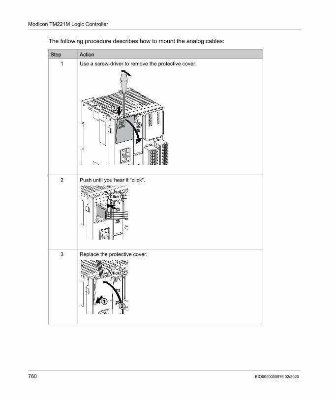
Modicon TM221M Logic Controller
The following procedure describes how to mount the analog cables:
Step Action1 Use a screw-driver to remove the protective cover.
2 Push until you hear it “click”.
3 Replace the protective cover.
760 EIO0000000976 02/2020
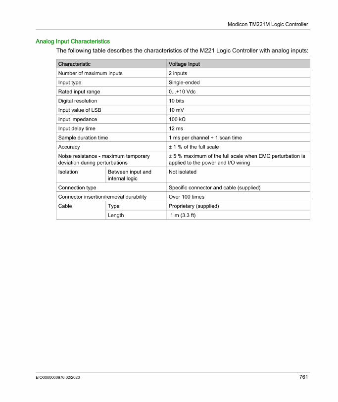
Modicon TM221M Logic Controller
Analog Input CharacteristicsThe following table describes the characteristics of the M221 Logic Controller with analog inputs:
Characteristic Voltage InputNumber of maximum inputs 2 inputsInput type Single-endedRated input range 0...+10 VdcDigital resolution 10 bitsInput value of LSB 10 mVInput impedance 100 kΩ Input delay time 12 msSample duration time 1 ms per channel + 1 scan timeAccuracy ± 1 % of the full scaleNoise resistance - maximum temporary deviation during perturbations
± 5 % maximum of the full scale when EMC perturbation is applied to the power and I/O wiring
Isolation Between input and internal logic
Not isolated
Connection type Specific connector and cable (supplied)Connector insertion/removal durability Over 100 timesCable Type Proprietary (supplied)
Length 1 m (3.3 ft)
EIO0000000976 02/2020 761

Modicon TM221M Logic Controller
Wiring DiagramThe following figure shows the wiring diagram of the M221 Logic Controller analog inputs:
The (-) poles are connected internally.
For more information, refer to the Wiring Best Practices (see page 603).
Pin Wire ColorAN0 Red0 V BlackAN1 Red0 V Black
762 EIO0000000976 02/2020

Modicon TM221M Logic Controller
TM221ME16R / TM221ME16RG
Section 11.2TM221ME16R / TM221ME16RG
OverviewThis chapter describes the TM221ME16R / TM221ME16RG controllers.
What Is in This Section?This section contains the following topics:
Topic PageTM221ME16R / TM221ME16RG Presentation 764TM221ME16R / TM221ME16RG Digital Inputs 770TM221ME16R / TM221ME16RG Digital Outputs 774TM221ME16R / TM221ME16RG Analog Inputs 778
EIO0000000976 02/2020 763

Modicon TM221M Logic Controller
TM221ME16R / TM221ME16RG Presentation
OverviewThe following features are integrated into the TM221ME16R (screw) and TM221ME16RG (spring) controllers: 8 digital inputs 4 regular inputs 4 fast inputs (HSC)
8 digital outputs 8 relay outputs
2 analog inputs Communication port 1 serial line port 1 USB mini-B programming port 1 Ethernet port
764 EIO0000000976 02/2020

Modicon TM221M Logic Controller
DescriptionThe following figure shows the different components of the controllers:
N° Description Refer to1 Status LEDs –2 Input removable terminal block Rules for Removable Screw Terminal
Block (see page 604)Rules for Removable Spring Terminal Block (see page 605)
3 Output removable terminal block
4 Clip-on lock for 35 mm (1.38 in.) top hat section rail (DIN-rail ) DIN Rail (see page 593)5 USB mini-B programming port / For terminal connection to a
programming PC (EcoStruxure Machine Expert - Basic)USB mini-B programming port (see page 867)
6 24 Vdc power supply Power supply (see page 610)7 Ethernet port / RJ45 connector Ethernet port (see page 869)8 Serial line port 1 / RJ45 connector (RS-232 or RS-485) Serial line 1 (see page 872)9 Run/Stop switch Run/Stop switch (see page 568)
EIO0000000976 02/2020 765

Modicon TM221M Logic Controller
10 Removable analog inputs cover –11 2 analog inputs Analog Inputs (see page 778)12 SD Card slot SD Card Slot (see page 571)13 I/O expansion connector –14 Protective cover (SD Card slot, Run/Stop switch and USB mini-
B programming port)–
15 Locking hook –16 Battery holder Installing and Replacing the Battery
(see page 553)
N° Description Refer to
766 EIO0000000976 02/2020

Modicon TM221M Logic Controller
Status LEDsThe following figure shows the status LEDs:
The following table describes the status LEDs:
Label Function Type Color Status Description
Controller States(1) Prg Port Communication
Application Execution
PWR Power Green On Indicates that power is applied.Off Indicates that power is removed.
RUN Machine Status Green On Indicates that the controller is running a valid application.
Flashing Indicates that the controller has a valid application that is stopped.
Off Indicates that the controller is not programmed.* ERR LED is also On during booting process.
NOTE: For information about the LEDs integrated into the Ethernet connector, refer to Ethernet Status LEDs (see page 871)(1) For more information about the controller state description, refer to the M221 Logic Controller - Programming Guide (see page 62).(2) The controller detected an error but remains in RUNNING state. The ERR LED on the controller flashes. For more information, refer to M221 Logic Controller - Programming Guide (see page 213).
EIO0000000976 02/2020 767

Modicon TM221M Logic Controller
ERR Error Red On* EXCEPTION Restricted NOFlashing (with RUN status LED Off)
INTERNAL ERROR
Restricted NO
Slow flash Minor error detected(2)
Yes Depends on the RUN status LED
1 single flash No application Yes YesSD SD Card
Access (see page 571)
Green On Indicates that the SD card is being accessed.Flashing Indicates that an error was detected during the SD card
operation.Off Indicates no access (idle) or no card is present.
BAT Battery (see page 553)
Red On Indicates that the battery needs to be replaced.Flashing Indicates that the battery charge is low.Off Indicates that the battery is OK.
SL Serial line 1 (see page 872)
Green On Indicates the status of Serial line 1.Flashing Indicates activity on Serial line 1.Off Indicates no serial communication.
Label Function Type Color Status Description
Controller States(1) Prg Port Communication
Application Execution
* ERR LED is also On during booting process.
NOTE: For information about the LEDs integrated into the Ethernet connector, refer to Ethernet Status LEDs (see page 871)(1) For more information about the controller state description, refer to the M221 Logic Controller - Programming Guide (see page 62).(2) The controller detected an error but remains in RUNNING state. The ERR LED on the controller flashes. For more information, refer to M221 Logic Controller - Programming Guide (see page 213).
768 EIO0000000976 02/2020

Modicon TM221M Logic Controller
DimensionsThe following figure shows the external dimensions of the controllers:
EIO0000000976 02/2020 769

Modicon TM221M Logic Controller
TM221ME16R / TM221ME16RG Digital Inputs
OverviewThis M221 Logic Controller has embedded digital inputs: 4 regular inputs 4 fast inputs which can be used as 100 kHz HSC inputsFor more information, refer to Input Management (see page 560).
Regular Input CharacteristicsThe following table describes the characteristics of the TM221M Logic Controller regular inputs:
DANGERFIRE HAZARD Use only the correct wire sizes for the current capacity of the I/O channels and power supplies. For relay output (2 A) wiring, use conductors of at least 0.5 mm2 (AWG 20) with a temperature
rating of at least 80 °C (176 °F). For common conductors of relay output wiring (7 A), or relay output wiring greater than 2 A,
use conductors of at least 1.0 mm2 (AWG 16) with a temperature rating of at least 80 °C (176 °F).
Failure to follow these instructions will result in death or serious injury.
WARNINGUNINTENDED EQUIPMENT OPERATIONDo not exceed any of the rated values specified in the environmental and electrical characteristics tables.Failure to follow these instructions can result in death, serious injury, or equipment damage.
Characteristic ValueNumber of regular inputs 4 inputs (I2, I3, I4, I5)Number of channel groups 1 common line for I0...I7Input type Type 1 (IEC/EN 61131-2)Logic type Sink/SourceInput voltage range 24 VdcRated input voltage 19.2...28.8 VdcRated input current 7 mAInput impedance 3.4 kΩ
770 EIO0000000976 02/2020

Modicon TM221M Logic Controller
Fast Input CharacteristicsThe following table describes the characteristics of the TM221M Logic Controller fast inputs:
Input limit values Voltage at state 1 > 15 Vdc (15...28.8 Vdc)Voltage at state 0 < 5 Vdc (0...5 Vdc)Current at state 1 > 2.5 mACurrent at state 0 < 1.0 mA
Derating No deratingTurn on time 35 µs + filter value1
Turn off time 35 µs + filter value1
Isolation Between input and internal logic
500 Vac
Connection type TM221ME16R Removable screw terminal blocksTM221ME16RG Removable spring terminal blocks
Connector insertion/removal durability Over 100 timesCable Type Unshielded
Length Maximum 30 m (98 ft)1 For more information, refer to Integrator Filter Principle (see page 560)
Characteristic Value
Characteristic ValueNumber of fast inputs 4 inputs (I0, I1, I6, I7)Number of channel groups 1 common line for I0...I7Input type Type 1 (IEC/EN 61131-2)Logic type Sink/SourceRated input voltage 24 VdcInput voltage range 19.2...28.8 VdcRated input current 4.5 mAInput impedance 4.9 kΩInput limit values Voltage at state 1 > 15 Vdc (15...28.8 Vdc)
Voltage at state 0 < 5 Vdc (0...5 Vdc)Current at state 1 > 2.5 mACurrent at state 0 < 1.0 mA
Derating No deratingTurn on time 5 µs + filter value1
Turn off time 5 µs + filter value1
EIO0000000976 02/2020 771

Modicon TM221M Logic Controller
HSC maximum frequency Dual Phase 100 kHzSingle phase 100 kHz Frequency Meter 100 kHz
HSC supported operation mode Dual Phase [Pulse / Direction] Dual Phase [Quadrature X1] Dual Phase [Quadrature X2] Dual Phase [Quadrature X4] Single Phase Frequency Meter
Isolation Between input and internal logic
500 Vac
Between channel groups
500 Vac
Connection type TM221ME16R Removable screw terminal blockTM221ME16RG Removable spring terminal block
Connector insertion/removal durability Over 100 timesCable Type Shielded, including the 24 Vdc power supply
Length Maximum 10 m (32.8 ft)1 For more information, refer to Integrator Filter Principle (see page 560)
Characteristic Value
772 EIO0000000976 02/2020

Modicon TM221M Logic Controller
Wiring DiagramThe following figure presents the connection of the inputs to the sensors:
(1) The COM0 terminals are connected internally.A Sink wiring (positive logic).B Source wiring (negative logic).
Ix I0, I1, I6, I7
EIO0000000976 02/2020 773

Modicon TM221M Logic Controller
TM221ME16R / TM221ME16RG Digital Outputs
OverviewM221 Logic Controller with 8 relay outputs embedded.For more information on Output Management (see page 564).
Relay Output CharacteristicsThe following table describes the characteristics of the TM221M Logic Controller with relay outputs:
DANGERFIRE HAZARD Use only the correct wire sizes for the current capacity of the I/O channels and power supplies. For relay output (2 A) wiring, use conductors of at least 0.5 mm2 (AWG 20) with a temperature
rating of at least 80 °C (176 °F). For common conductors of relay output wiring (7 A), or relay output wiring greater than 2 A,
use conductors of at least 1.0 mm2 (AWG 16) with a temperature rating of at least 80 °C (176 °F).
Failure to follow these instructions will result in death or serious injury.
WARNINGUNINTENDED EQUIPMENT OPERATIONDo not exceed any of the rated values specified in the environmental and electrical characteristics tables.Failure to follow these instructions can result in death, serious injury, or equipment damage.
Characteristic ValueNumber of relay outputs 8 outputsNumber of channel groups 1 common line for Q0...Q3
1 common line for Q4...Q7Output type RelayContact type NO (Normally Open)Rated output voltage 24 Vdc, 240 VacMaximum voltage at 2 A 30 Vdc, 264 VacMinimum switching load 5 Vdc at 1 mARated output current 2 A
774 EIO0000000976 02/2020

Modicon TM221M Logic Controller
Power LimitationThe following table describes the power limitation of the TM221ME16R / TM221ME16RG relay outputs controllers depending on the voltage, the type of load, and the number of operations required.These controllers do not support capacitive loads.
Maximum output current 2 A per output7 A per common
Maximum output frequency with maximum load 20 operations per minuteDerating No deratingTurn on time Max. 10 msTurn off time Max. 10 msContact resistance 30 mΩ maxMechanical life 20 million operationsElectrical life Under resistive load See power limitation (see page 775)
Under inductive loadProtection against short circuit NoIsolation Between output and
internal logic500 Vac
Between channel groups
500 Vac
Connection type TM221ME16R Removable screw terminal blocksTM221ME16RG Removable spring terminal blocks
Connector insertion/removal durability Over 100 timesCable Type Unshielded
Length Max. 30 m (98 ft)
NOTE: Refer to Protecting Outputs from Inductive Load Damage (see page 607) for additional information concerning output protection.
Characteristic Value
WARNINGRELAY OUTPUTS WELDED CLOSED Always protect relay outputs from inductive alternating current load damage using an
appropriate external protective circuit or device. Do not connect relay outputs to capacitive loads.Failure to follow these instructions can result in death, serious injury, or equipment damage.
EIO0000000976 02/2020 775

Modicon TM221M Logic Controller
Power LimitationsVoltage 24 Vdc 120 Vac 240 Vac Number of
operationsPower of resistive loadsAC-12
– 240 VA80 VA
480 VA160 VA
100,000300,000
Power of inductive loadsAC-15 (cos ϕ = 0.35)
– 60 VA18 VA
120 VA36 VA
100,000300,000
Power of inductive loadsAC-14 (cos ϕ = 0.7)
– 120 VA36 VA
240 VA72 VA
100,000300,000
Power of resistive loadsDC-12
48 W16 W
– – 100,000300,000
Power of inductive loadsDC-13 L/R = 7 ms
24 W7.2 W
– – 100,000300,000
776 EIO0000000976 02/2020

Modicon TM221M Logic Controller
Wiring DiagramThe following figure presents the connection of the outputs to the load:
* Type T fuse(1) The COM1 and COM2 terminals are not connected internally.(2) To improve the life time of the contacts, and to protect from potential inductive load damage, you must
connect a free wheeling diode in parallel to each inductive DC load or an RC snubber in parallel of each inductive AC load
A Source wiring (positive logic).B Sink wiring (negative logic).
NOTE: The assigned fuse values have been specified for the maximum current characteristics of the controller I/O and associated commons. You may have other considerations that are applicable based on the unique types of input and output devices you connect, or conformance to local, national or applicable certification regulations and standards, and you should size your fuses accordingly.
WARNINGUNINTENDED EQUIPMENT OPERATIONDo not connect wires to unused terminals and/or terminals indicated as “No Connection (N.C.)”.Failure to follow these instructions can result in death, serious injury, or equipment damage.
EIO0000000976 02/2020 777

Modicon TM221M Logic Controller
TM221ME16R / TM221ME16RG Analog Inputs
OverviewThe M221 Logic Controllers have 2 analog inputs embedded.
DANGERFIRE HAZARD Use only the correct wire sizes for the current capacity of the I/O channels and power supplies. For relay output (2 A) wiring, use conductors of at least 0.5 mm2 (AWG 20) with a temperature
rating of at least 80 °C (176 °F). For common conductors of relay output wiring (7 A), or relay output wiring greater than 2 A,
use conductors of at least 1.0 mm2 (AWG 16) with a temperature rating of at least 80 °C (176 °F).
Failure to follow these instructions will result in death or serious injury.
WARNINGUNINTENDED EQUIPMENT OPERATIONDo not exceed any of the rated values specified in the environmental and electrical characteristics tables.Failure to follow these instructions can result in death, serious injury, or equipment damage.
778 EIO0000000976 02/2020

Modicon TM221M Logic Controller
The following procedure describes how to mount the analog cables:
Step Action1 Use a screw-driver to remove the protective cover.
2 Push until you hear it “click”.
3 Replace the protective cover.
EIO0000000976 02/2020 779

Modicon TM221M Logic Controller
Analog Input CharacteristicsThe following table describes the characteristics of the M221 Logic Controller with analog inputs:
Characteristic Voltage InputNumber of maximum inputs 2 inputsInput type Single-endedRated input range 0...+10 VdcDigital resolution 10 bitsInput value of LSB 10 mVInput impedance 100 kΩ Input delay time 12 msSample duration time 1 ms per channel + 1 scan timeAccuracy ± 1 % of the full scaleNoise resistance - maximum temporary deviation during perturbations
± 5 % maximum of the full scale when EMC perturbation is applied to the power and I/O wiring
Isolation Between input and internal logic
Not isolated
Connection type Specific connector and cable (supplied)Connector insertion/removal durability Over 100 timesCable Type Proprietary (supplied)
Length 1 m (3.3 ft)
780 EIO0000000976 02/2020

Modicon TM221M Logic Controller
Wiring DiagramThe following figure shows the wiring diagram of the Modicon M221 Logic Controller analog inputs:
The (-) poles are connected internally.
For more information, refer to the Wiring Best Practices (see page 603).
Pin Wire ColorAN0 Red0 V BlackAN1 Red0 V Black
EIO0000000976 02/2020 781

Modicon TM221M Logic Controller
TM221M16T / TM221M16TG
Section 11.3TM221M16T / TM221M16TG
OverviewThis chapter describes the TM221M16T / TM221M16TG controllers.
What Is in This Section?This section contains the following topics:
Topic PageTM221M16T / TM221M16TG Presentation 783TM221M16T / TM221M16TG Digital Inputs 789TM221M16T / TM221M16TG Digital Outputs 794TM221M16T / TM221M16TG Analog Inputs 799
782 EIO0000000976 02/2020

Modicon TM221M Logic Controller
TM221M16T / TM221M16TG Presentation
OverviewThe following features are integrated into the TM221M16T (screw) and TM221M16TG (spring) controllers: 8 digital inputs 4 regular inputs 4 fast inputs (HSC)
8 digital outputs 6 regular transistor outputs 2 fast transistor outputs
2 analog inputs Communication port 2 serial line ports 1 USB mini-B programming port
EIO0000000976 02/2020 783

Modicon TM221M Logic Controller
DescriptionThe following figure shows the different components of the controllers:
N° Description Refer to1 Status LEDs –2 Input removable terminal block Rules for Removable Screw Terminal
Block (see page 604)Rules for Removable Spring Terminal Block (see page 605)
3 Output removable terminal block
4 Clip-on lock for 35 mm (1.38 in.) top hat section rail (DIN-rail ) DIN Rail (see page 593)5 USB mini-B programming port / For terminal connection to a
programming PC (EcoStruxure Machine Expert - Basic)USB mini-B programming port (see page 867)
6 24 Vdc power supply Power supply (see page 610)7 Serial line port 2 / RJ45 connector (RS-485) Serial line 2 (see page 876)8 Serial line port 1 / RJ45 connector (RS-232 or RS-485) Serial line 1 (see page 872)9 Run/Stop switch Run/Stop switch (see page 568)
784 EIO0000000976 02/2020

Modicon TM221M Logic Controller
10 Removable analog inputs cover –11 2 analog inputs Analog Inputs (see page 799)12 SD Card slot SD Card Slot (see page 571)13 I/O expansion connector –14 Protective cover (SD Card slot, Run/Stop switch and USB mini-
B programming port)–
15 Locking hook –16 Battery holder Installing and Replacing the Battery
(see page 553)
N° Description Refer to
EIO0000000976 02/2020 785

Modicon TM221M Logic Controller
Status LEDsThe following figure shows the status LEDs:
The following table describes the status LEDs:
Label Function Type Color Status DescriptionController States(1)
Prg Port Communication
Application Execution
PWR Power Green On Indicates that power is applied.Off Indicates that power is removed.
RUN Machine Status Green On Indicates that the controller is running a valid application.
Flashing Indicates that the controller has a valid application that is stopped.
Off Indicates that the controller is not programmed.* ERR LED is also On during booting process.(1) For more information about the controller state description, refer to the M221 Logic Controller - Programming Guide (see page 62).(2) The controller detected an error but remains in RUNNING state. The ERR LED on the controller flashes. For more information, refer to M221 Logic Controller - Programming Guide (see page 213).
786 EIO0000000976 02/2020

Modicon TM221M Logic Controller
ERR Error Red On* EXCEPTION Restricted NOFlashing (with RUN status LED Off)
INTERNAL ERROR
Restricted NO
Slow flashing Minor error detected(2)
Yes Depends on the RUN status LED
1 single flash No application Yes YesSD SD Card Access
(see page 571)Green On Indicates that the SD card is being accessed.
Flashing Indicates that an error was detected during the SD card operation.
Off Indicates no access (idle) or no card is present.BAT Battery
(see page 553)Red On Indicates that the battery needs to be replaced.
Flashing Indicates that the battery charge is low.Off Indicates that the battery is OK.
SL1 Serial line 1 (see page 872)
Green On Indicates the status of Serial line 1.Flashing Indicates activity on Serial line 1.Off Indicates no serial communication.
SL2 Serial line 2 (see page 876)
Green On Indicates the status of Serial line 2.Flashing Indicates activity on Serial line 2.Off Indicates no serial communication.
Label Function Type Color Status DescriptionController States(1)
Prg Port Communication
Application Execution
* ERR LED is also On during booting process.(1) For more information about the controller state description, refer to the M221 Logic Controller - Programming Guide (see page 62).(2) The controller detected an error but remains in RUNNING state. The ERR LED on the controller flashes. For more information, refer to M221 Logic Controller - Programming Guide (see page 213).
EIO0000000976 02/2020 787

Modicon TM221M Logic Controller
DimensionsThe following figure shows the external dimensions of the controllers:
788 EIO0000000976 02/2020

Modicon TM221M Logic Controller
TM221M16T / TM221M16TG Digital Inputs
OverviewThis M221 Logic Controller has embedded digital inputs: 4 regular inputs 4 fast inputs which can be used as 100 kHz HSC inputsFor more information, refer to Input Management (see page 560).
Regular Input CharacteristicsThe following table describes the characteristics of the TM221M Logic Controller regular inputs:
DANGERFIRE HAZARD Use only the correct wire sizes for the current capacity of the I/O channels and power supplies. For relay output (2 A) wiring, use conductors of at least 0.5 mm2 (AWG 20) with a temperature
rating of at least 80 °C (176 °F). For common conductors of relay output wiring (7 A), or relay output wiring greater than 2 A,
use conductors of at least 1.0 mm2 (AWG 16) with a temperature rating of at least 80 °C (176 °F).
Failure to follow these instructions will result in death or serious injury.
WARNINGUNINTENDED EQUIPMENT OPERATIONDo not exceed any of the rated values specified in the environmental and electrical characteristics tables.Failure to follow these instructions can result in death, serious injury, or equipment damage.
Characteristic ValueNumber of regular inputs 4 inputs (I2, I3, I4, I5)Number of channel groups 1 common line for I0...I7Input type Type 1 (IEC/EN 61131-2)Logic type Sink/SourceInput voltage range 24 VdcRated input voltage 19.2...28.8 VdcRated input current 7 mAInput impedance 3.4 kΩ
EIO0000000976 02/2020 789

Modicon TM221M Logic Controller
Fast Input CharacteristicsThe following table describes the characteristics of the TM221M Logic Controller fast inputs:
Input limit values Voltage at state 1 > 15 Vdc (15...28.8 Vdc)Voltage at state 0 < 5 Vdc (0...5 Vdc)Current at state 1 > 2.5 mACurrent at state 0 < 1.0 mA
Derating see Derating Curve (see page 792)Turn on time 35 µs + filter value1
Turn off time 35 µs + filter value1
Isolation Between input and internal logic
500 Vac
Connection type TM221M16T Removable screw terminal blocksTM221M16TG Removable spring terminal blocks
Connector insertion/removal durability Over 100 timesCable Type Unshielded
Length Maximum 30 m (98 ft)1 For more information, refer to Integrator Filter Principle (see page 560)
Characteristic Value
Characteristic ValueNumber of fast inputs 4 inputs (I0, I1, I6, I7)Number of channel groups 1 common line for I0...I7Input type Type 1 (IEC/EN 61131-2)Logic type Sink/SourceRated input voltage 24 VdcInput voltage range 19.2...28.8 VdcRated input current 4.5 mAInput impedance 4.9 kΩInput limit values Voltage at state 1 > 15 Vdc (15...28.8 Vdc)
Voltage at state 0 < 5 Vdc (0...5 Vdc)Current at state 1 2.6 mACurrent at state 0 < 1.0 mA
Derating see Derating Curve (see page 792)Turn on time 5 µs + filter value1
Turn off time 5 µs + filter value1
790 EIO0000000976 02/2020

Modicon TM221M Logic Controller
HSC maximum frequency Dual Phase 100 kHzSingle phase 100 kHz Frequency Meter 100 kHz
HSC supported operation mode Dual Phase [Pulse / Direction] Dual Phase [Quadrature X1] Dual Phase [Quadrature X2] Dual Phase [Quadrature X4] Single Phase Frequency Meter
Isolation Between input and internal logic
500 Vac
Between channel groups
500 Vac
Connection type TM221M16T Removable screw terminal blockTM221M16TG Removable spring terminal block
Connector insertion/removal durability Over 100 timesCable Type Shielded, including the 24 Vdc power supply
Length Maximum 10 m (32.8 ft)1 For more information, refer to Integrator Filter Principle (see page 560)
Characteristic Value
EIO0000000976 02/2020 791

Modicon TM221M Logic Controller
Derating CurvesThe following figures show the derating curves of the embedded digital inputs:
X Input simultaneous ON ratioY Input voltage
X Ambient temperatureY Input simultaneous ON ratio
792 EIO0000000976 02/2020

Modicon TM221M Logic Controller
Wiring DiagramThe following figure presents the connection of the inputs to the sensors:
(1) The COM0 terminals are connected internally.A Sink wiring (positive logic).B Source wiring (negative logic).
Ix I0, I1, I6, I7
EIO0000000976 02/2020 793

Modicon TM221M Logic Controller
TM221M16T / TM221M16TG Digital Outputs
OverviewThe TM221M16T and TM221M16TG have digital outputs embedded: 6 regular transistor outputs 2 fast transistor outputsFor more information, refer to Output Management (see page 564).
Regular Transistor Output CharacteristicsThe following table describes the characteristics of the TM221M Logic Controller regular transistor outputs:
DANGERFIRE HAZARD Use only the correct wire sizes for the current capacity of the I/O channels and power supplies. For relay output (2 A) wiring, use conductors of at least 0.5 mm2 (AWG 20) with a temperature
rating of at least 80 °C (176 °F). For common conductors of relay output wiring (7 A), or relay output wiring greater than 2 A,
use conductors of at least 1.0 mm2 (AWG 16) with a temperature rating of at least 80 °C (176 °F).
Failure to follow these instructions will result in death or serious injury.
WARNINGUNINTENDED EQUIPMENT OPERATIONDo not exceed any of the rated values specified in the environmental and electrical characteristics tables.Failure to follow these instructions can result in death, serious injury, or equipment damage.
Characteristic ValueNumber of regular transistor outputs 6 regular outputs (Q2...Q7)Number of channel groups 1 common line for Q0...Q7Output type TransistorLogic type SourceRated output voltage 24 VdcOutput voltage range 19.2...28.8 VdcRated output current 0.5 A
794 EIO0000000976 02/2020

Modicon TM221M Logic Controller
Total output current 4 AVoltage drop 1 Vdc maxLeakage current when switched off 0.1 mAMaximum power of filament lamp 12 W maxDerating see Derating Curve (see page 797)Turn on time Q2...Q3 Max. 50 µs
Q4...Q7 Max. 300 µsTurn off time Q2...Q3 Max. 50 µs
Q4...Q7 Max. 300 µsProtection against short circuit YesShort circuit output peak current 1.3 AAutomatic rearming after short circuit or overload Yes, every 1 sClamping voltage Max. 39 Vdc ± 1 VdcSwitching frequency Under resistive load 100 Hz max.Isolation Between output and
internal logic500 Vac
Connection type TM221M16T Removable screw terminal blocksTM221M16TG Removable spring terminal blocks
Connector insertion/removal durability Over 100 timesCable Type Unshielded
Length Max 30 m (98 ft)
NOTE: Refer to Protecting Outputs from Inductive Load Damage (see page 607) for additional information concerning output protection.
Characteristic Value
EIO0000000976 02/2020 795

Modicon TM221M Logic Controller
Fast Transistor Output CharacteristicsThe following table describes the characteristics of the TM221M Logic Controller fast transistor outputs:
Characteristic ValueNumber of fast transistor outputs 2 outputs (Q0, Q1)Number of channel groups 1 common line for Q0...Q7Output type TransistorLogic type SourceRated output voltage 24 VdcOutput voltage range 19.2...28.8 VdcRated output current 0.5 ATotal output current 4 AMaximum power of filament lamp 12 W maxDerating see Derating Curve (see page 797)Turn on time (10 mA < output current < 100 mA) Max. 5 µsTurn off time (10 mA < output current < 100 mA) Max. 5 µsProtection against short circuit YesShort circuit output peak current 1.3 A max.Automatic rearming after short circuit or overload Yes, every 1 sProtection against reverse polarity YesClamping voltage Typ. 39 Vdc +/- 1 VdcMaximum output frequency PLS/PWM/PTO/FREQGEN 100 kHzIsolation Between output and internal logic 500 VacConnection type TM221M16T Removable screw terminal blocks
TM221M16TG Removable spring terminal blocksConnector insertion/removal durability Over 100 timesCable Type Shielded, including 24 Vdc power supply
Length Maximum 3 m (9.84 ft)
NOTE: Refer to Protecting Outputs from Inductive Load Damage (see page 607) for additional information concerning output protection.
796 EIO0000000976 02/2020

Modicon TM221M Logic Controller
Derating CurvesThe following figures show the derating curves of the embedded digital outputs:
X Output simultaneous ON ratioY Output voltage
X Ambient temperatureY Output simultaneous ON ratio
p
EIO0000000976 02/2020 797

Modicon TM221M Logic Controller
Wiring DiagramThe following figure presents the connection of the outputs to the load:
* Type T fuse(1) The V+ terminals are connected internally.
Qx Q0, Q1
798 EIO0000000976 02/2020

Modicon TM221M Logic Controller
TM221M16T / TM221M16TG Analog Inputs
OverviewThe M221 Logic Controllers have 2 analog inputs embedded.
DANGERFIRE HAZARD Use only the correct wire sizes for the current capacity of the I/O channels and power supplies. For relay output (2 A) wiring, use conductors of at least 0.5 mm2 (AWG 20) with a temperature
rating of at least 80 °C (176 °F). For common conductors of relay output wiring (7 A), or relay output wiring greater than 2 A,
use conductors of at least 1.0 mm2 (AWG 16) with a temperature rating of at least 80 °C (176 °F).
Failure to follow these instructions will result in death or serious injury.
WARNINGUNINTENDED EQUIPMENT OPERATIONDo not exceed any of the rated values specified in the environmental and electrical characteristics tables.Failure to follow these instructions can result in death, serious injury, or equipment damage.
EIO0000000976 02/2020 799

Modicon TM221M Logic Controller
The following procedure describes how to mount the analog cables:
Step Action1 Use a screw-driver to remove the protective cover.
2 Push until you hear it “click”.
3 Replace the protective cover.
800 EIO0000000976 02/2020

Modicon TM221M Logic Controller
Analog Input CharacteristicsThe following table describes the characteristics of the M221 Logic Controller with analog inputs:
Characteristic Voltage InputNumber of maximum inputs 2 inputsInput type Single-endedRated input range 0...+10 VdcDigital resolution 10 bitsInput value of LSB 10 mVInput impedance 100 kΩ Input delay time 12 msSample duration time 1 ms per channel + 1 scan timeAccuracy ± 1 % of the full scaleNoise resistance - maximum temporary deviation during perturbations
± 5 % maximum of the full scale when EMC perturbation is applied to the power and I/O wiring
Isolation Between input and internal logic
Not isolated
Connection type Specific connector and cable (supplied)Connector insertion/removal durability Over 100 timesCable Type Proprietary (supplied)
Length 1 m (3.3 ft)
EIO0000000976 02/2020 801

Modicon TM221M Logic Controller
Wiring DiagramThe following figure shows the wiring diagram of the Modicon M221 Logic Controller analog inputs:
The (-) poles are connected internally.
For more information, refer to the Wiring Best Practices (see page 603).
Pin Wire ColorAN0 Red0 V BlackAN1 Red0 V Black
802 EIO0000000976 02/2020

Modicon TM221M Logic Controller
TM221ME16T / TM221ME16TG
Section 11.4TM221ME16T / TM221ME16TG
OverviewThis chapter describes the TM221ME16T / TM221ME16TG controllers.
What Is in This Section?This section contains the following topics:
Topic PageTM221ME16T / TM221ME16TG Presentation 804TM221ME16T / TM221ME16TG Digital Inputs 810TM221ME16T / TM221ME16TG Digital Outputs 815TM221ME16T / TM221ME16TG Analog Inputs 820
EIO0000000976 02/2020 803

Modicon TM221M Logic Controller
TM221ME16T / TM221ME16TG Presentation
OverviewThe following features are integrated into the TM221ME16T (screw) and TM221ME16TG (spring) controllers: 8 digital inputs 4 regular inputs 4 fast inputs (HSC)
8 digital outputs 6 regular transistor outputs 2 fast transistor outputs
2 analog inputs Communication port 1 serial line port 1 USB mini-B programming port 1 Ethernet port
804 EIO0000000976 02/2020

Modicon TM221M Logic Controller
DescriptionThe following figure shows the different components of the controllers:
N° Description Refer to1 Status LEDs –2 Input removable terminal block Rules for Removable Screw Terminal
Block (see page 604)Rules for Removable Spring Terminal Block (see page 605)
3 Output removable terminal block
4 Clip-on lock for 35 mm (1.38 in.) top hat section rail (DIN-rail ) DIN Rail (see page 593)5 USB mini-B programming port / For terminal connection to a
programming PC (EcoStruxure Machine Expert - Basic)USB mini-B programming port (see page 867)
6 24 Vdc power supply Power supply (see page 610)7 Ethernet port / RJ45 connector Ethernet port (see page 869)8 Serial line port 1 / RJ45 connector (RS-232 or RS-485) Serial line 1 (see page 872)9 Run/Stop switch Run/Stop switch (see page 568)
EIO0000000976 02/2020 805

Modicon TM221M Logic Controller
10 Removable analog inputs cover –11 2 analog inputs Analog Inputs (see page 820)12 SD Card slot SD Card Slot (see page 571)13 I/O expansion connector –14 Protective cover (SD Card slot, Run/Stop switch and USB mini-
B programming port)–
15 Locking hook –16 Battery holder Installing and Replacing the Battery
(see page 553)
N° Description Refer to
806 EIO0000000976 02/2020

Modicon TM221M Logic Controller
Status LEDsThe following figure shows the status LEDs:
The following table describes the status LEDs:
Label Function Type Color Status Description
Controller States(1) Prg Port Communication
Application Execution
PWR Power Green On Indicates that power is applied.Off Indicates that power is removed.
RUN Machine Status
Green On Indicates that the controller is running a valid application.
Flashing Indicates that the controller has a valid application that is stopped.
Off Indicates that the controller is not programmed.* ERR LED is also On during booting process.
NOTE: For information about the LEDs integrated into the Ethernet connector, refer to Ethernet Status LEDs (see page 871)(1) For more information about the controller state description, refer to the M221 Logic Controller - Programming Guide (see page 62).(2) The controller detected an error but remains in RUNNING state. The ERR LED on the controller flashes. For more information, refer to M221 Logic Controller - Programming Guide (see page 213).
EIO0000000976 02/2020 807

Modicon TM221M Logic Controller
ERR Error Red On* EXCEPTION Restricted NOFlashing (with RUN status LED Off)
INTERNAL ERROR
Restricted NO
Slow flash Minor error detected(2)
Yes Depends on the RUN status LED
1 single flash No application Yes YesSD SD Card
Access (see page 571)
Green On Indicates that the SD card is being accessed.Flashing Indicates that an error was detected during the SD card
operation.Off Indicates no access (idle) or no card is present.
BAT Battery (see page 553)
Red On Indicates that the battery needs to be replaced.Flashing Indicates that the battery charge is low.Off Indicates that the battery is OK.
SL Serial line 1 (see page 872)
Green On Indicates the status of Serial line 1.Flashing Indicates activity on Serial line 1.Off Indicates no serial communication.
Label Function Type Color Status Description
Controller States(1) Prg Port Communication
Application Execution
* ERR LED is also On during booting process.
NOTE: For information about the LEDs integrated into the Ethernet connector, refer to Ethernet Status LEDs (see page 871)(1) For more information about the controller state description, refer to the M221 Logic Controller - Programming Guide (see page 62).(2) The controller detected an error but remains in RUNNING state. The ERR LED on the controller flashes. For more information, refer to M221 Logic Controller - Programming Guide (see page 213).
808 EIO0000000976 02/2020

Modicon TM221M Logic Controller
DimensionsThe following figure shows the external dimensions of the controllers:
EIO0000000976 02/2020 809

Modicon TM221M Logic Controller
TM221ME16T / TM221ME16TG Digital Inputs
OverviewThis M221 Logic Controller has embedded digital inputs: 4 regular inputs 4 fast inputs which can be used as 100 kHz HSC inputsFor more information, refer to Input Management (see page 560).
Regular Input CharacteristicsThe following table describes the characteristics of the TM221M Logic Controller with transistor regular inputs:
DANGERFIRE HAZARD Use only the correct wire sizes for the current capacity of the I/O channels and power supplies. For relay output (2 A) wiring, use conductors of at least 0.5 mm2 (AWG 20) with a temperature
rating of at least 80 °C (176 °F). For common conductors of relay output wiring (7 A), or relay output wiring greater than 2 A,
use conductors of at least 1.0 mm2 (AWG 16) with a temperature rating of at least 80 °C (176 °F).
Failure to follow these instructions will result in death or serious injury.
WARNINGUNINTENDED EQUIPMENT OPERATIONDo not exceed any of the rated values specified in the environmental and electrical characteristics tables.Failure to follow these instructions can result in death, serious injury, or equipment damage.
Characteristic ValueNumber of regular inputs 4 inputs (I2, I3, I4, I5)Number of channel groups 1 common line for I0....I7Input type Type 1 (IEC/EN 61131-2)Logic type Sink/SourceRated input voltage 24 VdcInput voltage range 19.2...28.8 VdcRated input current 7 mA
810 EIO0000000976 02/2020

Modicon TM221M Logic Controller
Fast Input CharacteristicsThe following table describes the characteristics of the TM221M Logic Controller fast inputs:
Input impedance 3.4 kΩInput limit values Voltage at state 1 > 15 Vdc (15...28.8 Vdc)
Voltage at state 0 < 5 Vdc (0...5 Vdc)Current at state 1 > 2.5 mACurrent at state 0 < 1.0 mA
Derating see Derating Curve (see page 813)Turn on time 35 µs + filter value1
Turn off time 35 µs + filter value1
Isolation Between input and internal logic
500 Vac
Connection type TM221ME16T Removable screw terminal blocksTM221ME16TG Removable spring terminal blocks
Connector insertion/removal durability Over 100 timesCable Type Unshielded
Length Maximum 30 m (98 ft)1 For more information, refer to Integrator Filter Principle (see page 560)
Characteristic Value
Characteristic ValueNumber of fast inputs 4 inputs (I0, I1, I6, I7)Number of channel groups 1 common line for I0...I7Input type Type 1 (IEC/EN 61131-2)Logic type Sink/SourceRated input voltage 24 VdcInput voltage range 19.2...28.8 VdcRated input current 4.5 mAInput impedance 4.9 kΩInput limit values Voltage at state 1 > 15 Vdc (15...28.8 Vdc)
Voltage at state 0 < 5 Vdc (0...5 Vdc)Current at state 1 > 2.5 mACurrent at state 0 < 1.0 mA
Derating see Derating Curve (see page 813)Turn on time 5 µs + filter value1
EIO0000000976 02/2020 811

Modicon TM221M Logic Controller
Turn off time 5 µs + filter value1
HSC maximum frequency Dual Phase 100 kHzSingle phase 100 kHz Frequency Meter 100 kHz
HSC supported operation mode Dual Phase [Pulse / Direction] Dual Phase [Quadrature X1] Dual Phase [Quadrature X2] Dual Phase [Quadrature X4] Single Phase Frequency Meter
Isolation Between input and internal logic
500 Vac
Between channel groups
500 Vac
Connection type TM221ME16T Removable screw terminal blockTM221ME16TG Removable spring terminal block
Connector insertion/removal durability Over 100 timesCable Type Shielded, including the 24 Vdc power supply
Length Maximum 10 m (32.8 ft)1 For more information, refer to Integrator Filter Principle (see page 560)
Characteristic Value
812 EIO0000000976 02/2020

Modicon TM221M Logic Controller
Derating CurvesThe following figures show the derating curves of the embedded digital inputs:
X Input simultaneous ON ratioY Input voltage
X Ambient temperatureY Input simultaneous ON ratio
EIO0000000976 02/2020 813

Modicon TM221M Logic Controller
Wiring DiagramThe following figure presents the connection of the inputs to the sensors:
(1) The COM0 terminals are connected internally.A Sink wiring (positive logic).B Source wiring (negative logic).
Ix I0, I1, I6, I7
814 EIO0000000976 02/2020

Modicon TM221M Logic Controller
TM221ME16T / TM221ME16TG Digital Outputs
OverviewThe TM221ME16T and TM221ME16TG have 8 digital outputs embedded: 6 regular transistor outputs 2 fast transistor outputsFor more information, refer to Output Management (see page 564).
Regular Transistor Output CharacteristicsThe following table describes the characteristics of the TM221M Logic Controller regular transistor outputs:
DANGERFIRE HAZARD Use only the correct wire sizes for the current capacity of the I/O channels and power supplies. For relay output (2 A) wiring, use conductors of at least 0.5 mm2 (AWG 20) with a temperature
rating of at least 80 °C (176 °F). For common conductors of relay output wiring (7 A), or relay output wiring greater than 2 A,
use conductors of at least 1.0 mm2 (AWG 16) with a temperature rating of at least 80 °C (176 °F).
Failure to follow these instructions will result in death or serious injury.
WARNINGUNINTENDED EQUIPMENT OPERATIONDo not exceed any of the rated values specified in the environmental and electrical characteristics tables.Failure to follow these instructions can result in death, serious injury, or equipment damage.
Characteristic ValueNumber of regular transistor outputs 6 regular outputs (Q2...Q7)Number of channel groups 1 common line for Q0...Q7Output type TransistorLogic type SourceRated output voltage 24 VdcOutput voltage range 19.2...28.8 VdcRated output current 0.5 A
EIO0000000976 02/2020 815

Modicon TM221M Logic Controller
Fast Transistor Output CharacteristicsThe following table describes the characteristics of the TM221M Logic Controller fast transistor outputs:
Total output current 3 AVoltage drop 1 Vdc maxLeakage current when switched off 0.1 mAMaximum power of filament lamp 12 W maxDerating see Derating Curve (see page 818)Turn on time Q2...Q3 Max. 50 µs
Q4...Q7 Max. 300 µsTurn off time Q2...Q3 Max. 50 µs
Q4...Q7 Max. 300 µsProtection against short circuit YesShort circuit output peak current 1.3 AAutomatic rearming after short circuit or overload Yes, every 1 sClamping voltage Max. 39 Vdc ± 1 VdcSwitching frequency Under resistive load 100 Hz max.Isolation Between output and
internal logic500 Vac
Connection type TM221ME16T Removable screw terminal blocksTM221ME16TG Removable spring terminal blocks
Connector insertion/removal durability Over 100 timesCable Type Unshielded
Length Max 30 m (98 ft)
NOTE: Refer to Protecting Outputs from Inductive Load Damage (see page 607) for additional information concerning output protection.
Characteristic Value
Characteristic ValueNumber of fast transistor outputs 2 outputs (Q0, Q1)Number of channel groups 1 common line for Q0...Q7Output type TransistorLogic type SourceRated output voltage 24 VdcOutput voltage range 19.2...28.8 VdcRated output current 0.5 A
816 EIO0000000976 02/2020

Modicon TM221M Logic Controller
Total output current 4 AMaximum power of filament lamp 12 W maxDerating see Derating Curve (see page 818)Turn on time (10 mA < output current < 100 mA) Max. 5 µsTurn off time (10 mA < output current < 100 mA) Max. 5 µsProtection against short circuit YesShort circuit output peak current 1.3 A max.Automatic rearming after short circuit or overload Yes, every 1 sProtection against reverse polarity YesClamping voltage Typ. 39 Vdc +/- 1 VdcMaximum output frequency PLS/PWM/PTO/FREQGEN 100 kHzIsolation Between output and
internal logic500 Vac
Connection type TM221ME16T Removable screw terminal blocksTM221ME16TG Removable spring terminal blocks
Connector insertion/removal durability Over 100 timesCable Type Shielded, including 24 Vdc power supply
Length Maximum 3 m (9.84 ft)
NOTE: Refer to Protecting Outputs from Inductive Load Damage (see page 607) for additional information concerning output protection.
Characteristic Value
EIO0000000976 02/2020 817

Modicon TM221M Logic Controller
Derating CurvesThe following figures show the derating curves of the embedded digital outputs:
X Output simultaneous ON ratioY Output voltage
X Ambient temperatureY Output simultaneous ON ratio
818 EIO0000000976 02/2020

Modicon TM221M Logic Controller
Wiring DiagramThe following figure presents the connection of the outputs to the load:
* Type T fuse(1) The V+ terminals are connected internally.
Qx Q0, Q1
EIO0000000976 02/2020 819

Modicon TM221M Logic Controller
TM221ME16T / TM221ME16TG Analog Inputs
OverviewThe M221 Logic Controllers have 2 analog inputs embedded.
DANGERFIRE HAZARD Use only the correct wire sizes for the current capacity of the I/O channels and power supplies. For relay output (2 A) wiring, use conductors of at least 0.5 mm2 (AWG 20) with a temperature
rating of at least 80 °C (176 °F). For common conductors of relay output wiring (7 A), or relay output wiring greater than 2 A,
use conductors of at least 1.0 mm2 (AWG 16) with a temperature rating of at least 80 °C (176 °F).
Failure to follow these instructions will result in death or serious injury.
WARNINGUNINTENDED EQUIPMENT OPERATIONDo not exceed any of the rated values specified in the environmental and electrical characteristics tables.Failure to follow these instructions can result in death, serious injury, or equipment damage.
820 EIO0000000976 02/2020

Modicon TM221M Logic Controller
The following procedure describes how to mount the analog cables:
Step Action1 Use a screw-driver to remove the protective cover.
2 Push until you hear it “click”.
3 Replace the protective cover.
EIO0000000976 02/2020 821

Modicon TM221M Logic Controller
Analog Input CharacteristicsThe following table describes the characteristics of the M221 Logic Controller with analog inputs:
Characteristic Voltage InputNumber of maximum inputs 2 inputsInput type Single-endedRated input range 0...+10 VdcDigital resolution 10 bitsInput value of LSB 10 mVInput impedance 100 kΩ Input delay time 12 msSample duration time 1 ms per channel + 1 scan timeAccuracy ± 1 % of the full scaleNoise resistance - maximum temporary deviation during perturbations
± 5 % maximum of the full scale when EMC perturbation is applied to the power and I/O wiring
Isolation Between input and internal logic
Not isolated
Connection type Specific connector and cable (supplied)Connector insertion/removal durability Over 100 timesCable Type Proprietary (supplied)
Length 1 m (3.3 ft)
822 EIO0000000976 02/2020

Modicon TM221M Logic Controller
Wiring Diagram The following figure shows the wiring diagram of the Modicon M221 Logic Controller analog inputs:
The (-) poles are connected internally.
For more information, refer to the Wiring Best Practices (see page 603).
Pin Wire ColorAN0 Red0 V BlackAN1 Red0 V Black
EIO0000000976 02/2020 823

Modicon TM221M Logic Controller
TM221M32TK
Section 11.5TM221M32TK
OverviewThis chapter describes the TM221M32TK controllers.
What Is in This Section?This section contains the following topics:
Topic PageTM221M32TK Presentation 825TM221M32TK Digital Inputs 830TM221M32TK Digital Outputs 835TM221M32TK Analog Inputs 840
824 EIO0000000976 02/2020

Modicon TM221M Logic Controller
TM221M32TK Presentation
OverviewThe following features are integrated into the TM221M32TK (HE10) controllers: 16 digital inputs 12 regular inputs 4 fast inputs (HSC)
16 digital outputs 14 regular transistor outputs 2 fast transistor outputs
2 analog inputs Communication port 2 serial line ports 1 USB mini-B programming port
DescriptionThe following figure shows the different components of the controller:
N° Description Refer to1 Status LEDs –2 Input HE10 (MIL20) connector HE10 (MIL 20) connector cable list3 Output HE10 (MIL20) connector
EIO0000000976 02/2020 825

Modicon TM221M Logic Controller
4 Clip-on lock for 35 mm (1.38 in.) top hat section rail (DIN-rail ) DIN Rail (see page 593)5 USB mini-B programming port / For terminal connection to a
programming PC (EcoStruxure Machine Expert - Basic)USB mini-B programming port (see page 867)
6 24 Vdc power supply Power supply (see page 610)7 Serial line port 2 / RJ45 connector (RS-485) Serial line 2 (see page 876)8 Serial line port 1 / RJ45 connector (RS-232 or RS-485) Serial line 1 (see page 872)9 Run/Stop switch Run/Stop switch (see page 568)10 Removable analog inputs cover –11 2 analog inputs Analog Inputs (see page 840)12 SD Card slot SD Card Slot (see page 571)13 I/O expansion connector –14 Protective cover (SD Card slot, Run/Stop switch and USB mini-
B programming port)–
15 Locking hook –16 Battery holder Installing and Replacing the Battery
(see page 553)
N° Description Refer to
826 EIO0000000976 02/2020

Modicon TM221M Logic Controller
Status LEDsThe following figure shows the status LEDs:
The following table describes the status LEDs:
Label Function Type
Color Status Description
Controller States(1) Prg Port Communication
Application Execution
PWR Power Green On Indicates that power is applied.Off Indicates that power is removed.
RUN Machine Status
Green On Indicates that the controller is running a valid application.
Flashing Indicates that the controller has a valid application that is stopped.
Off Indicates that the controller is not programmed.* ERR LED is also On during booting process.(1) For more information about the controller state description, refer to the M221 Logic Controller - Programming Guide (see page 62).(2) The controller detected an error but remains in RUNNING state. The ERR LED on the controller flashes. For more information, refer to M221 Logic Controller - Programming Guide (see page 213).
EIO0000000976 02/2020 827

Modicon TM221M Logic Controller
ERR Error Red On* EXCEPTION Restricted NOFlashing (with RUN status LED Off)
INTERNAL ERROR
Restricted NO
Slow flashing Minor error detected(2)
Yes Depends on the RUN status LED
1 single flash No application Yes YesSD SD Card
Access (see page 571)
Green On Indicates that the SD card is being accessed.Flashing Indicates that an error was detected during the SD card
operation.Off Indicates no access (idle) or no card is present.
BAT Battery (see page 553)
Red On Indicates that the battery needs to be replaced.Flashing Indicates that the battery charge is low.Off Indicates that the battery is OK.
SL1 Serial line 1 (see page 872)
Green On Indicates the status of Serial line 1.Flashing Indicates activity on Serial line 1.Off Indicates no serial communication.
SL2 Serial line 2 (see page 876)
Green On Indicates the status of Serial line 2.Flashing Indicates activity on Serial line 2.Off Indicates no serial communication.
Label Function Type
Color Status Description
Controller States(1) Prg Port Communication
Application Execution
* ERR LED is also On during booting process.(1) For more information about the controller state description, refer to the M221 Logic Controller - Programming Guide (see page 62).(2) The controller detected an error but remains in RUNNING state. The ERR LED on the controller flashes. For more information, refer to M221 Logic Controller - Programming Guide (see page 213).
828 EIO0000000976 02/2020

Modicon TM221M Logic Controller
DimensionsThe following figure shows the external dimensions of the controller:
EIO0000000976 02/2020 829

Modicon TM221M Logic Controller
TM221M32TK Digital Inputs
OverviewThis M221 Logic Controller has embedded digital inputs: 12 regular inputs 4 fast inputs which can be used as 100 kHz HSC inputsFor more information, refer to Input Management (see page 560).
Regular Input CharacteristicsThe following table describes the characteristics of the TM221M Logic Controller regular inputs:
DANGERFIRE HAZARD Use only the correct wire sizes for the current capacity of the I/O channels and power supplies. For relay output (2 A) wiring, use conductors of at least 0.5 mm2 (AWG 20) with a temperature
rating of at least 80 °C (176 °F). For common conductors of relay output wiring (7 A), or relay output wiring greater than 2 A,
use conductors of at least 1.0 mm2 (AWG 16) with a temperature rating of at least 80 °C (176 °F).
Failure to follow these instructions will result in death or serious injury.
WARNINGUNINTENDED EQUIPMENT OPERATIONDo not exceed any of the rated values specified in the environmental and electrical characteristics tables.Failure to follow these instructions can result in death, serious injury, or equipment damage.
Characteristic ValueNumber of regular inputs 12 inputsNumber of channel groups 1 common line for I0...I7
1 common line for I8...I15Input type Type 1 (IEC/EN 61131-2)Logic type Sink/SourceRated input voltage 24 VdcInput voltage range 19.2...28.8 VdcRated input current 7 mA
830 EIO0000000976 02/2020

Modicon TM221M Logic Controller
Fast Input CharacteristicsThe following table describes the characteristics of the TM221M Logic Controller fast inputs:
Input impedance 3.4 kΩInput limit values Voltage at state 1 > 15 Vdc (15...28.8 Vdc)
Voltage at state 0 < 5 Vdc (0...5 Vdc)Current at state 1 > 2.5 mACurrent at state 0 < 1.0 mA
Derating see Derating Curve (see page 833)Turn on time 35 µs + filter value1
Turn off time 35 µs + filter value1
Isolation Between input and internal logic
500 Vac
Connection type HE10 (MIL 20) connectorsConnector insertion/removal durability Over 100 timesCable Type Unshielded
Length Maximum 30 m (98 ft)1 For more information, refer to Integrator Filter Principle (see page 560)
Characteristic Value
Characteristic ValueNumber of fast inputs 4 inputs (I0, I1, I6, I7)Number of channel groups 1 common line for I0...I7Input type Type 1 (IEC/EN 61131-2)Logic type Sink/SourceRated input voltage 24 VdcInput voltage range 19.2...28.8 VdcRated input current 4.5 mAInput impedance 4.9 kΩInput limit values Voltage at state 1 > 15 Vdc (15...28.8 Vdc)
Voltage at state 0 < 5 Vdc (0...5 Vdc)Current at state 1 > 2.5 mACurrent at state 0 < 1.0 mA
Derating see Derating Curve (see page 833)Turn on time 5 µs + filter value1
Turn off time 5 µs + filter value1
EIO0000000976 02/2020 831

Modicon TM221M Logic Controller
HSC maximum frequency Dual Phase 100 kHzSingle phase 100 kHz Frequency Meter 100 kHz
HSC supported operation mode Dual Phase [Pulse / Direction] Dual Phase [Quadrature X1] Dual Phase [Quadrature X2] Dual Phase [Quadrature X4] Single Phase Frequency Meter
Isolation Between input and internal logic
500 Vac
Between channel groups
500 Vac
Connection type TM221M32TK HE10 (MIL 20) connectorConnector insertion/removal durability Over 100 timesCable Type Shielded, including the 24 Vdc power supply
Length Maximum 10 m (32.8 ft)1 For more information, refer to Integrator Filter Principle (see page 560)
Characteristic Value
832 EIO0000000976 02/2020

Modicon TM221M Logic Controller
Derating CurvesThe following figures show the derating curves of the embedded digital inputs:
X Input simultaneous ON ratioY Input voltage
X Ambient temperatureY Input simultaneous ON ratio
EIO0000000976 02/2020 833

Modicon TM221M Logic Controller
Wiring Diagram with Free-Wire CableThe following figure presents the connection of the inputs to the sensors:
(1) The COM terminals are not connected internally.A Sink wiring (positive logic).B Source wiring (negative logic).
Ix I0, I1, I6, I7
For more information on the cable color for TWDFCW30K/TWDFCW50K, refer to TWDFCW••K Cable Description (see page 549).
834 EIO0000000976 02/2020

Modicon TM221M Logic Controller
TM221M32TK Digital Outputs
OverviewThe TM221M32TK has 16 digital outputs embedded: 14 regular transistor outputs 2 fast transistor outputsFor more information, refer to Output Management (see page 564).
Regular Transistor Output CharacteristicsThe following table describes the characteristics of the TM221M Logic Controller regular transistor outputs:
DANGERFIRE HAZARD Use only the correct wire sizes for the current capacity of the I/O channels and power supplies. For relay output (2 A) wiring, use conductors of at least 0.5 mm2 (AWG 20) with a temperature
rating of at least 80 °C (176 °F). For common conductors of relay output wiring (7 A), or relay output wiring greater than 2 A,
use conductors of at least 1.0 mm2 (AWG 16) with a temperature rating of at least 80 °C (176 °F).
Failure to follow these instructions will result in death or serious injury.
WARNINGUNINTENDED EQUIPMENT OPERATIONDo not exceed any of the rated values specified in the environmental and electrical characteristics tables.Failure to follow these instructions can result in death, serious injury, or equipment damage.
Characteristic ValueNumber of regular transistor outputs 14 regular outputs (Q2...Q15)Number of channel groups 1 common line for Q0...Q15Output type TransistorLogic type SourceRated output voltage 24 VdcOutput voltage range 19.2...28.8 VdcRated output current 0.1 A
EIO0000000976 02/2020 835

Modicon TM221M Logic Controller
Total output current (Q0...Q15) 1.6 AVoltage drop 1 Vdc maxLeakage current when switched off 0.1 mAMaximum power of filament lamp 2.4 W maxDerating See Derating Curves (see page 838)Turn on time Q2...Q3 Max. 50 µs
Q4...Q15 Max. 300 µsTurn off time Q2...Q3 Max. 50 µs
Q4...Q15 Max. 300 µsProtection against short circuit YesShort circuit output peak current 0.25 AAutomatic rearming after short circuit or overload Yes, every 1 sClamping voltage Max. 39 Vdc ± 1 VdcSwitching frequency Under resistive load 100 Hz max.Isolation Between output and
internal logic500 Vac
Connection type TM221M32TK HE10 (MIL 20) connectorsConnector insertion/removal durability Over 100 timesCable Type Unshielded
Length Max 30 m (98 ft)
NOTE: Refer to Protecting Outputs from Inductive Load Damage (see page 607) for additional information concerning output protection.
Characteristic Value
836 EIO0000000976 02/2020

Modicon TM221M Logic Controller
Fast Transistor Output CharacteristicsThe following table describes the characteristics of the TM221M Logic Controller fast transistor outputs:
Characteristic ValueNumber of fast transistor outputs 2 outputs (Q0, Q1)Number of channel groups 1 common line for Q0...Q15Output type TransistorLogic type SourceRated output voltage 24 VdcOutput voltage range 19.2...28.8 VdcRated output current 0.1 ATotal output current (Q0...Q15) 1.6 AMaximum power of filament lamp 2.4 W maxDerating See Derating Curves (see page 838)Turn on time (10 mA < output current < 100 mA) Max. 5 µsTurn off time (10 mA < output current < 100 mA) Max. 5 µsProtection against short circuit YesShort circuit output peak current 1.3 A max.Automatic rearming after short circuit or overload Yes, every 1 sProtection against reverse polarity YesClamping voltage Typ. 39 Vdc +/- 1 VdcMaximum output frequency PWM 100 kHz
PLS 100 kHzIsolation Between output
and internal logic500 Vac
Connection type TM221M32TK HE10 (MIL 20) connectorsConnector insertion/removal durability Over 100 timesCable Type Shielded, including 24 Vdc power supply
Length Maximum 3 m (9.84 ft)
NOTE: Refer to Protecting Outputs from Inductive Load Damage (see page 607) for additional information concerning output protection.
EIO0000000976 02/2020 837

Modicon TM221M Logic Controller
Derating CurvesThe following figures show the derating curves of the embedded digital outputs:
X Output simultaneous ON ratioY Output voltage
X Ambient temperatureY Output simultaneous ON ratio
838 EIO0000000976 02/2020

Modicon TM221M Logic Controller
Wiring Diagram with Free-Wire CableThe following figure presents the connection of the outputs to the load:
* Type T fuse
Qx Q0, Q1
For more information on the cable color for TWDFCW30K/TWDFCW50K, refer to TWDFCW••K Cable Description (see page 549).
EIO0000000976 02/2020 839

Modicon TM221M Logic Controller
TM221M32TK Analog Inputs
OverviewThe M221 Logic Controllers have 2 analog inputs embedded.
DANGERFIRE HAZARD Use only the correct wire sizes for the current capacity of the I/O channels and power supplies. For relay output (2 A) wiring, use conductors of at least 0.5 mm2 (AWG 20) with a temperature
rating of at least 80 °C (176 °F). For common conductors of relay output wiring (7 A), or relay output wiring greater than 2 A,
use conductors of at least 1.0 mm2 (AWG 16) with a temperature rating of at least 80 °C (176 °F).
Failure to follow these instructions will result in death or serious injury.
WARNINGUNINTENDED EQUIPMENT OPERATIONDo not exceed any of the rated values specified in the environmental and electrical characteristics tables.Failure to follow these instructions can result in death, serious injury, or equipment damage.
840 EIO0000000976 02/2020

Modicon TM221M Logic Controller
The following procedure describes how to mount the analog cables:
Step Action1 Use a screw-driver to remove the protective cover.
2 Push until you hear it “click”.
3 Replace the protective cover.
EIO0000000976 02/2020 841

Modicon TM221M Logic Controller
Analog Input CharacteristicsThe following table describes the characteristics of the M221 Logic Controller with analog inputs:
Characteristic Voltage InputNumber of maximum inputs 2 inputsInput type Single-endedRated input range 0...+10 VdcDigital resolution 10 bitsInput value of LSB 10 mVInput impedance 100 kΩ Input delay time 12 msSample duration time 1 ms per channel + 1 scan timeAccuracy ± 1 % of the full scaleNoise resistance - maximum temporary deviation during perturbations
± 5 % maximum of the full scale when EMC perturbation is applied to the power and I/O wiring
Isolation Between input and internal logic
Not isolated
Connection type Specific connector and cable (supplied)Connector insertion/removal durability Over 100 timesCable Type Proprietary (supplied)
Length 1 m (3.3 ft)
842 EIO0000000976 02/2020

Modicon TM221M Logic Controller
Wiring DiagramThe following figure shows the wiring diagram of the Modicon M221 Logic Controller analog inputs:
The (-) poles are connected internally.
For more information, refer to the Wiring Best Practices (see page 603).
Pin Wire ColorAN0 Red0 V BlackAN1 Red0 V Black
EIO0000000976 02/2020 843

Modicon TM221M Logic Controller
TM221ME32TK
Section 11.6TM221ME32TK
OverviewThis chapter describes the TM221ME32TK controller.
What Is in This Section?This section contains the following topics:
Topic PageTM221ME32TK Presentation 845TM221ME32TK Digital Inputs 850TM221ME32TK Digital Outputs 855TM221ME32TK Analog Inputs 860
844 EIO0000000976 02/2020

Modicon TM221M Logic Controller
TM221ME32TK Presentation
OverviewThe following features are integrated into the TM221ME32TK (HE10) controllers: 16 digital inputs 12 regular inputs 4 fast inputs (HSC)
16 digital outputs 14 regular transistor outputs 2 fast transistor outputs
2 analog inputs Communication port 1 serial line port 1 USB mini-B programming port 1 Ethernet port
DescriptionThe following figure shows the different components of the controller:
EIO0000000976 02/2020 845

Modicon TM221M Logic Controller
N° Description Refer to1 Status LEDs –2 Input HE10 (MIL20) connector HE10 (MIL 20) connector cable list3 Output HE10 (MIL20) connector4 Clip-on lock for 35 mm (1.38 in.) top hat section rail (DIN-rail ) DIN Rail (see page 593)5 USB mini-B programming port / For terminal connection to a
programming PC (EcoStruxure Machine Expert - Basic)USB mini-B programming port (see page 867)
6 24 Vdc power supply Power supply (see page 610)7 Ethernet port / RJ45 connector Ethernet port (see page 869)8 Serial line port 1 / RJ45 connector (RS-232 or RS-485) Serial line 1 (see page 872)9 Run/Stop switch Run/Stop switch (see page 568)10 Removable analog inputs cover –11 2 analog inputs Analog Inputs (see page 860)12 SD Card slot SD Card Slot (see page 571)13 I/O expansion connector –14 Protective cover (SD Card slot, Run/Stop switch and USB mini-
B programming port)–
15 Locking hook –16 Battery holder Installing and Replacing the Battery
(see page 553)
846 EIO0000000976 02/2020

Modicon TM221M Logic Controller
Status LEDsThe following figure shows the status LEDs:
The following table describes the status LEDs:
Label Function Type Color Status Description
Controller States(1) Prg Port Communication
Application Execution
PWR Power Green On Indicates that power is applied.Off Indicates that power is removed.
RUN Machine Status Green On Indicates that the controller is running a valid application.
Flashing Indicates that the controller has a valid application that is stopped.
Off Indicates that the controller is not programmed.* ERR LED is also On during booting process.
NOTE: For information about the LEDs integrated into the Ethernet connector, refer to Ethernet Status LEDs (see page 871)(1) For more information about the controller state description, refer to the M221 Logic Controller - Programming Guide (see page 62).(2) The controller detected an error but remains in RUNNING state. The ERR LED on the controller flashes. For more information, refer to M221 Logic Controller - Programming Guide (see page 213).
EIO0000000976 02/2020 847

Modicon TM221M Logic Controller
ERR Error Red On* EXCEPTION Restricted NOFlashing (with RUN status LED Off)
INTERNAL ERROR
Restricted NO
Slow flash Minor error detected(2)
Yes Depends on the RUN status LED
1 single flash No application Yes YesSD SD Card
Access (see page 571)
Green On Indicates that the SD card is being accessed.Flashing Indicates that an error was detected during the SD card
operation.Off Indicates no access (idle) or no card is present.
BAT Battery (see page 553)
Red On Indicates that the battery needs to be replaced.Flashing Indicates that the battery charge is low.Off Indicates that the battery is OK.
SL Serial line 1 (see page 872)
Green On Indicates the status of Serial line 1.Flashing Indicates activity on Serial line 1.Off Indicates no serial communication.
Label Function Type Color Status Description
Controller States(1) Prg Port Communication
Application Execution
* ERR LED is also On during booting process.
NOTE: For information about the LEDs integrated into the Ethernet connector, refer to Ethernet Status LEDs (see page 871)(1) For more information about the controller state description, refer to the M221 Logic Controller - Programming Guide (see page 62).(2) The controller detected an error but remains in RUNNING state. The ERR LED on the controller flashes. For more information, refer to M221 Logic Controller - Programming Guide (see page 213).
848 EIO0000000976 02/2020

Modicon TM221M Logic Controller
DimensionsThe following figure shows the external dimension controller:
EIO0000000976 02/2020 849

Modicon TM221M Logic Controller
TM221ME32TK Digital Inputs
OverviewThis M221 Logic Controller has embedded digital inputs: 12 regular inputs 4 fast inputs which can be used as 100 kHz HSC inputsFor more information, refer to Input Management (see page 560).
Regular Input CharacteristicsThe following table describes the characteristics of the TM221M Logic Controller regular inputs:
DANGERFIRE HAZARD Use only the correct wire sizes for the current capacity of the I/O channels and power supplies. For relay output (2 A) wiring, use conductors of at least 0.5 mm2 (AWG 20) with a temperature
rating of at least 80 °C (176 °F). For common conductors of relay output wiring (7 A), or relay output wiring greater than 2 A,
use conductors of at least 1.0 mm2 (AWG 16) with a temperature rating of at least 80 °C (176 °F).
Failure to follow these instructions will result in death or serious injury.
WARNINGUNINTENDED EQUIPMENT OPERATIONDo not exceed any of the rated values specified in the environmental and electrical characteristics tables.Failure to follow these instructions can result in death, serious injury, or equipment damage.
Characteristic ValueNumber of regular inputs 12 inputsNumber of channel groups 1 common line for I0...I7
1 common line for I8...I15Input type Type 1 (IEC/EN 61131-2)Logic type Sink/SourceRated input voltage 24 VdcInput voltage range 19.2...28.8 VdcRated input current 7 mA
850 EIO0000000976 02/2020

Modicon TM221M Logic Controller
Fast Input CharacteristicsThe following table describes the characteristics of the TM221M Logic Controller fast inputs:
Input impedance 3.4 kΩInput limit values Voltage at state 1 > 15 Vdc (15...28.8 Vdc)
Voltage at state 0 < 5 Vdc (0...5 Vdc)Current at state 1 > 2.5 mACurrent at state 0 < 1.0 mA
Derating see Derating Curve (see page 851)Turn on time 35 µs + filter value1
Turn off time I2...I5: 35 µs1
I8...I15: 100 µs1
Isolation Between input and internal logic
500 Vac
Connection type HE10 (MIL 20) connectorsConnector insertion/removal durability Over 100 timesCable Type Unshielded
Length Maximum 30 m (98 ft)1 For more information, refer to Integrator Filter Principle (see page 560)
Characteristic Value
Characteristic ValueNumber of fast inputs 4 inputs (I0, I1, I6, I7)Number of channel groups 1 common line for I0...I7Input type Type 1 (IEC/EN 61131-2)Logic type Sink/SourceRated input voltage 24 VdcInput voltage range 19.2...28.8 VdcRated input current 4.5 mAInput impedance 4.9 kΩInput limit values Voltage at state 1 > 15 Vdc (15...28.8 Vdc)
Voltage at state 0 < 5 Vdc (0...5 Vdc)Current at state 1 > 2.5 mACurrent at state 0 < 1.0 mA
Derating see Derating Curve (see page 853)Turn on time 5 µs + filter value1
EIO0000000976 02/2020 851

Modicon TM221M Logic Controller
Turn off time 5 µs + filter value1
HSC maximum frequency Dual Phase 100 kHzSingle phase 100 kHz Frequency Meter 100 kHz
HSC supported operation mode Dual Phase [Pulse / Direction] Dual Phase [Quadrature X1] Dual Phase [Quadrature X2] Dual Phase [Quadrature X4] Single Phase Frequency Meter
Isolation Between input and internal logic
500 Vac
Between channel groups
500 Vac
Connection type TM221ME32TK HE10 (MIL 20) connectorConnector insertion/removal durability Over 100 timesCable Type Shielded, including the 24 Vdc power supply
Length Maximum 10 m (32.8 ft)1 For more information, refer to Integrator Filter Principle (see page 560)
Characteristic Value
852 EIO0000000976 02/2020

Modicon TM221M Logic Controller
Derating CurvesThe following figures show the derating curves of the embedded digital inputs:
X Input simultaneous ON ratioY Input voltage
X Ambient temperatureY Input simultaneous ON ratio
EIO0000000976 02/2020 853

Modicon TM221M Logic Controller
Wiring Diagram with Free-Wire CableThe following figure presents the connection of the inputs to the sensors:
(1) The COM terminals are not connected internally.A Sink wiring (positive logic).B Source wiring (negative logic).
Ix I0, I1, I6, I7
For more information on the cable color for TWDFCW30K/TWDFCW50K, refer to TWDFCW••K Cable Description (see page 550).
854 EIO0000000976 02/2020

Modicon TM221M Logic Controller
TM221ME32TK Digital Outputs
OverviewThe TM221ME32TK has 16 digital outputs embedded: 14 regular transistor outputs 2 fast transistor outputsFor more information, refer to Output Management (see page 564).
Regular Transistor Output CharacteristicsThe following table describes the characteristics of the TM221M Logic Controller regular transistor outputs:
DANGERFIRE HAZARD Use only the correct wire sizes for the current capacity of the I/O channels and power supplies. For relay output (2 A) wiring, use conductors of at least 0.5 mm2 (AWG 20) with a temperature
rating of at least 80 °C (176 °F). For common conductors of relay output wiring (7 A), or relay output wiring greater than 2 A,
use conductors of at least 1.0 mm2 (AWG 16) with a temperature rating of at least 80 °C (176 °F).
Failure to follow these instructions will result in death or serious injury.
WARNINGUNINTENDED EQUIPMENT OPERATIONDo not exceed any of the rated values specified in the environmental and electrical characteristics tables.Failure to follow these instructions can result in death, serious injury, or equipment damage.
Characteristic ValueNumber of regular transistor outputs 14 regular outputs (Q2...Q15)Number of channel groups 1 common line for Q0...Q15Output type TransistorLogic type SourceRated output voltage 24 VdcOutput voltage range 19.2...28.8 VdcRated output current 0.1 A
EIO0000000976 02/2020 855

Modicon TM221M Logic Controller
Fast Transistor Output CharacteristicsThe following table describes the characteristics of the TM221M Logic Controller fast transistor outputs:
Total output current (Q0...Q15) 1.6 AVoltage drop 1 Vdc maxLeakage current when switched off 0.1 mAMaximum power of filament lamp 2.4 W maxDerating See Derating Curves (see page 858)Turn on time Q2...Q3 Max. 50 µs
Q4...Q15 Max. 300 µsTurn off time Q2...Q3 Max. 50 µs
Q4...Q15 Max. 300 µsProtection against short circuit YesShort circuit output peak current 0.25 AAutomatic rearming after short circuit or overload Yes, every 1 sClamping voltage Max. 39 Vdc ± 1 VdcSwitching frequency Under resistive load 100 Hz max.Isolation Between output and
internal logic500 Vac
Connection type TM221ME32TK HE10 (MIL 20) connectorsConnector insertion/removal durability Over 100 timesCable Type Unshielded
Length Max 30 m (98 ft)
NOTE: Refer to Protecting Outputs from Inductive Load Damage (see page 607) for additional information concerning output protection.
Characteristic Value
Characteristic ValueNumber of fast transistor outputs 2 outputs (Q0, Q1)Number of channel groups 1 common line for Q0...Q15Output type TransistorLogic type SourceRated output voltage 24 VdcOutput voltage range 19.2...28.8 VdcRated output current 0.1 ATotal output current (Q0...Q15) 1.6 A
856 EIO0000000976 02/2020

Modicon TM221M Logic Controller
Maximum power of filament lamp 2.4 W maxDerating See Derating Curves (see page 858)Turn on time (10 mA < output current < 100 mA) Max. 5 µsTurn off time (10 mA < output current < 100 mA) Max. 5 µsProtection against short circuit YesShort circuit output peak current 1.3 A max.Automatic rearming after short circuit or overload Yes, every 1 sProtection against reverse polarity YesClamping voltage Typ. 39 Vdc +/- 1 VdcMaximum output frequency PLS/PWM/PTO/FREQGEN 100 kHzIsolation Between output and internal
logic500 Vac
Connection type TM221ME32TK HE10 (MIL 20) connectorsConnector insertion/removal durability Over 100 timesCable Type Shielded, including 24 Vdc power supply
Length Maximum 3 m (9.84 ft)
NOTE: Refer to Protecting Outputs from Inductive Load Damage (see page 607) for additional information concerning output protection.
Characteristic Value
EIO0000000976 02/2020 857

Modicon TM221M Logic Controller
Derating CurvesThe following figures show the derating curves of the embedded digital outputs:
X Output simultaneous ON ratioY Output voltage
X Ambient temperatureY Output simultaneous ON ratio
858 EIO0000000976 02/2020

Modicon TM221M Logic Controller
Wiring Diagram with Free-Wire CableThe following figure presents the connection of the outputs to the load:
* Type T fuse
Qx Q0, Q1
For more information on the cable color for TWDFCW30K/TWDFCW50K, refer to TWDFCW••K Cable Description (see page 549).
EIO0000000976 02/2020 859

Modicon TM221M Logic Controller
TM221ME32TK Analog Inputs
OverviewThe M221 Logic Controllers have 2 analog inputs embedded.
DANGERFIRE HAZARD Use only the correct wire sizes for the current capacity of the I/O channels and power supplies. For relay output (2 A) wiring, use conductors of at least 0.5 mm2 (AWG 20) with a temperature
rating of at least 80 °C (176 °F). For common conductors of relay output wiring (7 A), or relay output wiring greater than 2 A,
use conductors of at least 1.0 mm2 (AWG 16) with a temperature rating of at least 80 °C (176 °F).
Failure to follow these instructions will result in death or serious injury.
WARNINGUNINTENDED EQUIPMENT OPERATIONDo not exceed any of the rated values specified in the environmental and electrical characteristics tables.Failure to follow these instructions can result in death, serious injury, or equipment damage.
860 EIO0000000976 02/2020

Modicon TM221M Logic Controller
The following procedure describes how to mount the analog cables:
Step Action1 Use a screw-driver to remove the protective cover.
2 Push until you hear it “click”.
3 Replace the protective cover.
EIO0000000976 02/2020 861

Modicon TM221M Logic Controller
Analog Input CharacteristicsThe following table describes the characteristics of the M221 Logic Controller with analog inputs:
Characteristic Voltage InputNumber of maximum inputs 2 inputsInput type Single-endedRated input range 0...+10 VdcDigital resolution 10 bitsInput value of LSB 10 mVInput impedance 100 kΩ Input delay time 12 msSample duration time 1 ms per channel + 1 scan timeAccuracy ± 1 % of the full scaleNoise resistance - maximum temporary deviation during perturbations
± 5 % maximum of the full scale when EMC perturbation is applied to the power and I/O wiring
Isolation Between input and internal logic
Not isolated
Connection type Specific connector and cable (supplied)Connector insertion/removal durability Over 100 timesCable Type Proprietary (supplied)
Length 1 m (3.3 ft)
862 EIO0000000976 02/2020

Modicon TM221M Logic Controller
Wiring DiagramThe following figure shows the wiring diagram of the Modicon M221 Logic Controller analog inputs:
The (-) poles are connected internally.
For more information, refer to the Wiring Best Practices (see page 603).
Pin Wire ColorAN0 Red0 V BlackAN1 Red0 V Black
EIO0000000976 02/2020 863

Modicon TM221M Logic Controller
864 EIO0000000976 02/2020

Modicon M221Modicon M221 Logic Controller CommunicationEIO0000000976 02/2020
Modicon M221 Logic Controller Communication
Chapter 12Modicon M221 Logic Controller Communication
What Is in This Chapter?This chapter contains the following sections:
Section Topic Page12.1 Integrated Communication Ports 86612.2 Connecting the M221 Logic Controller to a PC 879
EIO0000000976 02/2020 865

Modicon M221 Logic Controller Communication
Integrated Communication Ports
Section 12.1Integrated Communication Ports
What Is in This Section?This section contains the following topics:
Topic PageUSB Mini-B Programming Port 867Ethernet Port 869Serial Line 1 872Serial Line 2 876
866 EIO0000000976 02/2020

Modicon M221 Logic Controller Communication
USB Mini-B Programming Port
OverviewThe USB Mini-B Port is the programming port you can use to connect a PC with a USB host port using EcoStruxure Machine Expert - Basic software. Using a typical USB cable, this connection is suitable for quick updates of the program or short duration connections to perform maintenance and inspect data values. It is not suitable for long-term connections such as commissioning or monitoring without the use of specially adapted cables to help minimize electromagnetic interference.
The following figure shows the location of the USB Mini-B programming port on the TM221C Logic Controller:
WARNINGUNINTENDED EQUIPMENT OPERATION OR INOPERABLE EQUIPMENT You must use a shielded USB cable such as a BMX XCAUSBH0•• secured to the functional
ground (FE) of the system for any long-term connection. Do not connect more than one controller at a time using USB connections. Do not use the USB port(s), if so equipped, unless the location is known to be non-hazardous.Failure to follow these instructions can result in death, serious injury, or equipment damage.
EIO0000000976 02/2020 867

Modicon M221 Logic Controller Communication
The following figure shows the location of the USB Mini-B programming port on the TM221M Logic Controller:
CharacteristicsThis table describes the characteristics of the USB Mini-B programming port:
Parameter USB Programming PortFunction Compatible with USB 2.0Connector type Mini-BIsolation NoneCable type Shielded
868 EIO0000000976 02/2020

Modicon M221 Logic Controller Communication
Ethernet Port
OverviewThe TM221•E••• are equipped with an Ethernet communication port.The following figure presents the location of the Ethernet port on the TM221C Logic Controller:
The following figure presents the location of the Ethernet port on the TM221M Logic Controller:
EIO0000000976 02/2020 869

Modicon M221 Logic Controller Communication
CharacteristicsThe following table describes Ethernet characteristics:
Pin AssignmentThe following figure presents the RJ45 Ethernet connector pin assignment:
The following table describes the RJ45 Ethernet connector pins:
NOTE: The controller supports the MDI/MDIX auto-crossover cable function. It is not necessary to use special Ethernet crossover cables to connect devices directly to this port (connections without an Ethernet hub or switch).
Characteristic DescriptionFunction Modbus TCP/IPConnector type RJ45Driver 10 M half duplex (auto negotiation)
100 M full duplex (auto negotiation)
Cable type ShieldedAutomatic cross-over detection Yes
Pin N° Signal1 TD+2 TD-3 RD+4 -5 -6 RD-7 -8 -
870 EIO0000000976 02/2020

Modicon M221 Logic Controller Communication
Status LEDThe following figures show the RJ45 connector status LED:
The following table describes the Ethernet status LEDs:
A change in the value of system bits %S34, %S35, or %S36 may provoke a reinitialization of the Ethernet channel. As a consequence, the Ethernet channel may not be available for several seconds after a change in the values of these System Bits (see page 241).
Label Description LEDColor Status Description
1: ACT Ethernet activity Green Off No activity, or logic controller is connected to a hub.
Flashing Activity2: LINK Ethernet link Yellow Off No link
On Link
EIO0000000976 02/2020 871

Modicon M221 Logic Controller Communication
Serial Line 1
OverviewThe serial line 1: can be used to communicate with devices supporting the Modbus protocol as either master or
slave, ASCII protocol (printer, modem...). provides a 5 Vdc power distribution.The following figure shows the location of the serial line 1 port on the TM221C Logic Controller:
The following figure shows the location of the serial line 1 port on the TM221M Logic Controller:
872 EIO0000000976 02/2020

Modicon M221 Logic Controller Communication
Characteristics
NOTE: Some devices provide voltage on RS485 serial connections. Do not connect these voltage lines to your controller as they may damage the controller serial port electronics and render the serial port inoperable.
Characteristic DescriptionFunction RS485 or RS232 software configuredConnector type RJ45Isolation Non-isolatedMaximum baud rate 1200 up to 115 200 bpsCable Type Shielded
Maximum length (between the controller and an isolated junction box)
15 m (49 ft) for RS4853 m (9.84 ft) for RS232
Polarization No5 Vdc power supply for RS485 Yes
NOTICEINOPERABLE EQUIPMENTUse only the VW3A8306R•• serial cable to connect RS485 devices to your controller.Failure to follow these instructions can result in equipment damage.
EIO0000000976 02/2020 873

Modicon M221 Logic Controller Communication
Pin AssignmentThe following figure shows the pins of the RJ45 connector:
The table below describes the pin assignment of the RJ45 connector:
CTS: Clear To SendN.C.: No ConnectionRTS: Ready To SendRxD: Received DataTxD: Transmitted Data
Pin RS232 RS4851 RxD N.C.2 TxD N.C.3 RTS N.C.4 N.C. D15 N.C. D06 CTS N.C.7 N.C.* 5 Vdc8 Common Common* 5 Vdc delivered by the controller. Do not connect.
WARNINGUNINTENDED EQUIPMENT OPERATIONDo not connect wires to unused terminals and/or terminals indicated as “No Connection (N.C.)”.Failure to follow these instructions can result in death, serious injury, or equipment damage.
874 EIO0000000976 02/2020

Modicon M221 Logic Controller Communication
Status LEDThe following figure shows the serial line 1 status LED of the TM221C Logic Controller:
The following figure shows the serial line 1 status LED of the TM221M Logic Controller:
The table below describes the status LED of the serial line 1:
Label Description LEDColor Status Description
SL1 Serial Line 1 Green On Indicates the activity of the serial line 1
Off Indicates no serial communication
EIO0000000976 02/2020 875

Modicon M221 Logic Controller Communication
Serial Line 2
OverviewThe serial line 2 is used to communicate with devices supporting the Modbus protocol as either a master or slave and ASCII Protocol (printer, modem...) and supports RS485 and terminal block.
Characteristics
Characteristic DescriptionFunction RS485 software configuredConnector type RJ45Isolation Non-isolatedMaximum baud rate 1200 up to 115 200 bpsCable Type Shielded
Maximum length 15 m (49 ft) for RS485Polarization No5 Vdc power supply for RS485 No
876 EIO0000000976 02/2020

Modicon M221 Logic Controller Communication
Pin AssignmentThe following figure presents the pins of the RJ45 connector:
The table below describes the pin assignment for RS485:
Pin RS485 Description1 N.C. No connection2 N.C. No connection3 N.C. No connection4 D1 Modbus SL: D1 (+/B) RS-485 2-wire5 D0 Modbus SL: D0 (-/A) RS-485 2-wire6 N.C. No connection7 N.C. No connection8 Common Common
WARNINGUNINTENDED EQUIPMENT OPERATIONDo not connect wires to unused terminals and/or terminals indicated as “No Connection (N.C.)”.Failure to follow these instructions can result in death, serious injury, or equipment damage.
EIO0000000976 02/2020 877

Modicon M221 Logic Controller Communication
Status LEDThe following graphic presents the status LED:
The table below describes the serial line 2 status LED:
Label Description LEDColor Status Description
SL2 Serial Line 2 Green On Indicates the activity of the serial line 2.
Off Indicates no serial communication.
878 EIO0000000976 02/2020

Modicon M221 Logic Controller Communication
Connecting the M221 Logic Controller to a PC
Section 12.2Connecting the M221 Logic Controller to a PC
Connecting the Controller to a PC
OverviewTo transfer, run, and monitor the applications, connect the controller to a computer, that has EcoStruxure Machine Expert - Basic 1.0 or later installed, using either a USB cable or an Ethernet connection (for those references that support an Ethernet port).
USB Mini-B Port ConnectionTCSXCNAMUM3P: This USB cable is suitable for short duration connections such as quick
updates or retrieving data values.BMXXCAUSBH018: Grounded and shielded, this USB cable is suitable for long duration
connections on a TM221C Logic Controller.BMXXCAUSBH045: Grounded and shielded, this USB cable is suitable for long duration
connections on a TM221M Logic Controller.NOTE: You can only connect 1 controller or any other device associated with EcoStruxure Machine Expert - Basic and its component to the PC at any one time.
NOTICEINOPERABLE EQUIPMENTAlways connect the communication cable to the PC before connecting it to the controller.Failure to follow these instructions can result in equipment damage.
WARNINGINSUFFICENT POWER FOR USB DOWNLOADDo not use a USB cable longer than 3m (9.8 ft) for USB powered download.Failure to follow these instructions can result in death, serious injury, or equipment damage.
EIO0000000976 02/2020 879

Modicon M221 Logic Controller Communication
The USB Mini-B Port is the programming port you can use to connect a PC with a USB host port using EcoStruxure Machine Expert - Basic software. Using a typical USB cable, this connection is suitable for quick updates of the program or short duration connections to perform maintenance and inspect data values. It is not suitable for long-term connections such as commissioning or monitoring without the use of specially adapted cables to help minimize electromagnetic interference.
The communication cable should be connected to the PC first to minimize the possibility of electrostatic discharge affecting the controller.The following illustration shows the USB connection to a PC on a TM221C Logic Controller:
The following illustration shows the USB connection to a PC on a TM221M Logic Controller:
WARNINGUNINTENDED EQUIPMENT OPERATION OR INOPERABLE EQUIPMENT You must use a shielded USB cable such as a BMX XCAUSBH0•• secured to the functional
ground (FE) of the system for any long-term connection. Do not connect more than one controller at a time using USB connections. Do not use the USB port(s), if so equipped, unless the location is known to be non-hazardous.Failure to follow these instructions can result in death, serious injury, or equipment damage.
880 EIO0000000976 02/2020

Modicon M221 Logic Controller Communication
To connect the USB cable to your controller, follow the steps below:
Ethernet Port ConnectionYou can also connect the controller to a PC using an Ethernet cable.The following illustration shows the Ethernet connection to a PC on a TM221C Logic Controller:
The following illustration shows the Ethernet connection to a PC on a TM221M Logic Controller:
To connect the controller to the PC, do the following:
Step Action1 1a If making a long-term connection using the cable BMXXCAUSBH045, or other cable with a
ground shield connection, be sure to securely connect the shield connector to the functional ground (FE) or protective ground (PE) of your system before connecting the cable to your controller and your PC.
1b If making a short-term connection using the cable TCSXCNAMUM3P or other non-grounded USB cable, proceed to step 2.
2 Connect your USB cable to the computer.3 Open the hinged access cover.4 Connect the Mini connector of your USB cable to the controller USB connector.
Step Action1 Connect your Ethernet cable to the PC.2 Connect your Ethernet cable to the Ethernet port on the controller.
EIO0000000976 02/2020 881

Modicon M221 Logic Controller Communication
882 EIO0000000976 02/2020

Modicon M221Modicon TMH2GDB Remote Graphic Display PartEIO0000000976 02/2020
Modicon TMH2GDB Remote Graphic Display Part
Part IVModicon TMH2GDB Remote Graphic Display Part
What Is in This Part?This part contains the following chapters:
Chapter Chapter Name Page13 Presentation 88514 Installation 89315 How to Use the Remote Graphic Display 91116 Setup Menu Functionality 91717 Creating an Operator Interface with EcoStruxure Machine Expert - Basic 929
EIO0000000976 02/2020 883

Modicon TMH2GDB Remote Graphic Display Part
884 EIO0000000976 02/2020

Modicon M221PresentationEIO0000000976 02/2020
Presentation
Chapter 13Presentation
IntroductionThis chapter provides information related to the description, technical presentation, certifications and standards of the Remote Graphic Display.
What Is in This Chapter?This chapter contains the following topics:
Topic PageDescription 886Technical Presentation 888Certifications and Standards 890Compatibility of The Remote Graphic Display 891
EIO0000000976 02/2020 885

Presentation
Description
OverviewThe Remote Graphic Display is a local control unit. It is used in conjunction with the Modicon M221 Logic Controller for monitoring, commissioning, operating, and maintenance activities.
System DescriptionWhen connecting the Remote Graphic Display to your logic controller, you can access the Setup menu (see page 917) page.You can also define customized pages (see page 929) with EcoStruxure Machine Expert - Basic.The Remote Graphic Display can be connected to your logic controller by the serial line (Serial or Serial 1). For more information, refer to Connecting the Remote Graphic Display (see page 903).
Physical DescriptionThis illustration presents the delivery content for a Remote Graphic Display:
1 Remote Graphic Display Instruction Sheet2 Remote Graphic Display3 Anti-rotation tee4 Installation nut5 Socket wrench (ZB5AZ905), tightening tool for the installation nut
886 EIO0000000976 02/2020

Presentation
Remote Graphic Display DescriptionThis illustration presents the Remote Graphic Display:
1 F1 key2 MOD key3 ESC key4 R1 to R4 keys5 Graphic screen6 Home key7 Information key8 F2 key9 Touch wheel/OK/Arrows10 Anti-rotation tee11 Installation nut12 Socket wrench (ZB5AZ905)13 RJ45 serial line (RS-485)14 Connector for functional ground (earth)
EIO0000000976 02/2020 887

Presentation
Technical Presentation
Enclosure RequirementsThe Remote Graphic Display components are designed as Zone B, Class A industrial equipment according to IEC/CISPR Publication 11. If they are used in environments other than those described in these standards, or in environments that do not meet the specifications in this manual, the ability to meet electromagnetic compatibility requirements in the presence of conducted and/or radiated interference may be reduced.All Remote Graphic Display components meet European Community (CE) requirements for open equipment as defined by IEC/EN 61131-2.
Environmental CharacteristicsThis equipment meets CE requirements as indicated in the table below. This equipment is intended for use in a pollution degree 2 industrial environment.
WARNINGUNINTENDED EQUIPMENT OPERATIONDo not exceed any of the rated values specified in the environmental and electrical characteristics tables.Failure to follow these instructions can result in death, serious injury, or equipment damage.
Characteristic SpecificationStandard compliance IEC/EN 61131-2
IEC/EN 61010-2-201Ambient operating temperature -15...50 °C (5...122 °F)Storage temperature -40...70 °C (-40...158 °F)Relative humidity Transport and storage
95 % (non-condensing)Operation
Pollution degree IEC/EN 60664-1 2Protection degree IEC/EN 61131-2 Front face: IP65 (when properly installed as
instructed)Back face: IP20
Corrosion immunity Atmosphere free from corrosive gasesOperating altitude 0...2000 m (0...6560 ft)Storage altitude 0...2000 m (0...6560 ft)
888 EIO0000000976 02/2020

Presentation
Electromagnetic SusceptibilityThe Remote Graphic Display components meet electromagnetic susceptibility specifications as indicated in this table:
Vibration resistance 2 g 3...150 hz maximum 1.5 mmMechanical shock resistance 147 m/s2 (482.285 ft/s2), 15 g for 11 ms
duration
Characteristic Specification
Characteristic Designed to specification RangeElectrostatic discharge IEC/EN 61000-4-2 8 kV (air discharge)
4 kV (contact discharge)Radiated electromagnetic field
IEC/EN 61000-4-3 10 V/m (80 MHz...1 GHz)3 V/m (1.4 GHz...2 GHz)1 V/m (2...3 GHz)
Magnetic field IEC/EN 61000-4-8 30 A/m 50 Hz, 60 HzFast transient burst IEC/EN 61000-4-4 1 kVSurge immunity IEC/EN 61000-4-5
IEC/EN 61131-2CM(1) DM(2)
0.5 kV 0.5 kVInduced electromagnetic field
IEC/EN 61000-4-6 10 Vrms (0.15...80 MHz)
Conducted emission IEC/EN 55011 (IEC/CISPR Publication 11)
DC power line: 10...150 kHz: 120...69 dBμV/m QP 150...1500 kHz: 79...63 dBμV/m QP 1.5...30 MHz: 63 dBμV/m QP
Radiated emission IEC/EN 55011 (IEC/CISPR Publication 11)
Class A, 10 m distance: 30...230 MHz: 40 dBμV/m QP 230 MHz...1 GHz: 47 dBμV/m QP
(1) Common mode(2) Differential mode
EIO0000000976 02/2020 889

Presentation
Certifications and Standards
IntroductionThe Remote Graphic Display is designed to conform to the main national and international standards concerning electronic industrial control devices: IEC/EN 61131-2 UL 508CThe Remote Graphic Display has obtained the following conformity marks: CE UL
890 EIO0000000976 02/2020

Presentation
Compatibility of The Remote Graphic Display
OverviewBefore using the Remote Graphic Display, verify the compatibility of the Remote Graphic Display with the version of EcoStruxure Machine Expert - Basic, the controller firmware version, and the functional level of the application.
Compatibility With EcoStruxure Machine Expert - BasicThe installed version of EcoStruxure Machine Expert - Basic must be equal to or greater than 1.0.NOTE: To display the installed version of EcoStruxure Machine Expert - Basic, click About on the Start Menu.
Compatibility with the Controller FirmwareThe firmware version of the M221 Logic Controller must be equal to or greater than 1.3.x.y.NOTE: To display the firmware version, click Commissioning → Connect, select M221 Logic Controller, and click Login. Under Selected Controller, the firmware version and controller are identified.You can update the firmware using one of the following methods: Controller Updates in EcoStruxure Machine Expert - Basic ExecLoader (Updating Firmware using Executive Loader Wizard (see page 95)) SD card (Firmware Management (see page 205))
Compatibility with the Functional Level of the ApplicationThe functional level of the application must be equal to or greater than level 3.0.NOTE: For more information, refer to functional level.
Incompatibility DetectionIf an incompatibility is detected between Remote Graphic Display and the functional level of the application, the following use cases occur:
EIO0000000976 02/2020 891

Presentation
Logic Controller Firmware Version
Remote Graphic Display Firmware Version
Consequence System Object Updates
>= V1.4.x.y V1.1IE40 for M221 is displayed on TMH2GDB at power-up
%SW185 = 0100 hex
The Remote Graphic Display shows the Incompatible device or incompatible application level screen.
%SW182 = 4: Remote Graphic Display firmware update required(1)
%SW183 = 2: Incompatible version of the display(1)
Update of the Remote Graphic Display firmware is not possible with this Remote Graphic Display firmware version.
>=V1.4.x.y V1.3IEx for M221 is displayed on TMH2GDB at power-up
%SW185 = 0103 hex
The Remote Graphic Display shows the Incompatible device or incompatible application level screen.
%SW182 = 4: Remote Graphic Display firmware update required(1)
%SW183 = 2: Incompatible version of the display(1)
Updating the Remote Graphic Display firmware is possible by using an SD card script (see page 206).
(1) Refer to %SW182 and %SW183 (see page 253) for more details.
892 EIO0000000976 02/2020

Modicon M221InstallationEIO0000000976 02/2020
Installation
Chapter 14Installation
IntroductionThis chapter provides information related to the installation of the Remote Graphic Display.
What Is in This Chapter?This chapter contains the following topics:
Topic PageInstallation and Maintenance Requirements 894Dimensions and Clearances 896Mounting 898Connecting the Remote Graphic Display 903Updating the Firmware 909
EIO0000000976 02/2020 893

Installation
Installation and Maintenance Requirements
Before StartingRead and understand this chapter before beginning the installation of your system.The use and application of the information contained herein require expertise in the design and programming of automated control systems. Only you, the user, machine builder or integrator, can be aware of all the conditions and factors present during installation and setup, operation, and maintenance of the machine or process, and can therefore determine the automation and associated equipment and the related safeties and interlocks which can be effectively and properly used. When selecting automation and control equipment, and any other related equipment or software, for a particular application, you must also consider any applicable local, regional, or national standards and/or regulations.Pay particular attention in conforming to any safety information, different electrical requirements, and normative standards that would apply to your machine or process in the use of this equipment.
Programming Considerations
Operating EnvironmentThis equipment has been designed to operate outside of any hazardous location. Only install this equipment in zones known to be free of a hazardous atmosphere.
DANGERHAZARD OF ELECTRIC SHOCK, EXPLOSION OR ARC FLASHReplace and secure all covers, accessories, hardware, cables, and wires and confirm that a proper ground connection exists before applying power to the unit.Failure to follow these instructions will result in death or serious injury.
WARNINGUNINTENDED EQUIPMENT OPERATION Only use software approved by Schneider Electric for use with this equipment. Update your application program every time you change the physical hardware configuration.Failure to follow these instructions can result in death, serious injury, or equipment damage.
894 EIO0000000976 02/2020

Installation
Installation Considerations
DANGERPOTENTIAL FOR EXPLOSIONInstall and use this equipment in non-hazardous locations only.Failure to follow these instructions will result in death or serious injury.
WARNINGUNINTENDED EQUIPMENT OPERATIONInstall and operate this equipment according to the conditions described in the section Technical Presentation.Failure to follow these instructions can result in death, serious injury, or equipment damage.
WARNINGUNINTENDED EQUIPMENT OPERATION Use appropriate safety interlocks where personnel and/or equipment hazards exist. Do not use this equipment in safety-critical machine functions unless the equipment is
otherwise designated as functional safety equipment and conforming to applicable regulations and standards.
Do not disassemble, repair, or modify this equipment. Do not connect any wiring to reserved, unused connections, or to connections designated as
No Connection (N.C.).Failure to follow these instructions can result in death, serious injury, or equipment damage.
EIO0000000976 02/2020 895

Installation
Dimensions and Clearances
IntroductionThis section describes the dimensions and the mounting clearances for the Remote Graphic Display.
DimensionsThis illustration describes the external dimensions of the Remote Graphic Display:
Minimum Clearances
WARNINGUNINTENDED EQUIPMENT OPERATION Place devices dissipating the most heat at the top of the cabinet and ensure adequate
ventilation. Avoid placing this equipment next to or above devices that might cause overheating. Install the equipment in a location providing the minimum clearances from all adjacent
structures and equipment as directed in this document. Install all equipment in accordance with the specifications in the related documentation.Failure to follow these instructions can result in death, serious injury, or equipment damage.
896 EIO0000000976 02/2020

Installation
The Remote Graphic Display has been designed as an IP65 product when properly installed, excluding the RJ45 connector. The Remote Graphic Display must be installed on the front panel of the cabinet or enclosure to achieve the IP65 rating. Clearances must be respected when installing the product.There are four types of clearances between: The Remote Graphic Display and all sides of the cabinet (including the panel door). The Remote Graphic Display connector and the wiring ducts. This distance reduces
electromagnetic interference between the Remote Graphic Display and the wiring ducts. The Remote Graphic Display and other heat generating devices installed in the same cabinet. The Remote Graphic Display and other Remote Graphic Display on the same panel door.This illustration describes the minimum clearances:
NOTE: Keep adequate spacing for proper ventilation and to maintain the operating temperature specified in the Environmental Characteristics (see page 888).
EIO0000000976 02/2020 897

Installation
Mounting
OverviewThis section presents how to install the Remote Graphic Display on the cabinet panel.
Mounting Hole LayoutThis diagram presents the drilling template for the Remote Graphic Display:
Prerequisites Before Installing the Remote Graphic DisplayBefore installing the Remote Graphic Display, verify that: The gasket must be uniform and undamaged. The installation panel or cabinet surface must be flat and smooth, with a tolerance of 0.5 mm
(0.019 in). The panel thickness must be between 1.5 mm and 6 mm if the cabinet panel is steel sheeting,
or between 3 mm and 6 mm if the cabinet panel is glass fiber reinforced plastic.
898 EIO0000000976 02/2020

Installation
Installing the Remote Graphic DisplayThis procedure describes how to install the Remote Graphic Display:
Step Action1 Insert the anti-rotation tee into the Remote Graphic Display.
NOTE: The rotating torque that can be supported by the Remote Graphic Display is 6 N.m (53.10 in-lb).
EIO0000000976 02/2020 899

Installation
2 Insert the Remote Graphic Display on the cabinet panel.Step Action
900 EIO0000000976 02/2020

Installation
Cleaning the Remote Graphic DisplayWhen the front panel of the Remote Graphic Display needs cleaning, wipe it with a soft cloth. If necessary, use a neutral detergent.
3 Install the nut and tighten it with the socket wrench (ZB5AZ905).
(1) 1,5...6 mm (0.06...0.24 in) if steel sheet or 3...6 mm (0.12...0.24 in) if glass fiber reinforced plastic (minimum GF30)
Step Action
NOTICEINOPERABLE EQUIPMENTDo not use any liquids containing acids, organic solvents, alcohol, or abrasive materials to clean the unit.Failure to follow these instructions can result in equipment damage.
EIO0000000976 02/2020 901

Installation
Care must be taken when wiping the surface of the Remote Graphic Display. Inadvertently pressing the keys while doing so may unintendedly engage programmed machine operations.
WARNINGUNINTENDED EQUIPMENT OPERATIONDo not press any of the keys while cleaning the surface of the equipment.Failure to follow these instructions can result in death, serious injury, or equipment damage.
902 EIO0000000976 02/2020

Installation
Connecting the Remote Graphic Display
OverviewThe Remote Graphic Display must be connected only to the Serial or Serial 1 port of the logic controller. These serial ports of the logic controllers provide the 5 Vdc power supply of the Remote Graphic Display. The Remote Graphic Display must be the only device connected to these serial ports (do not use a Tap-off box). The connection between the Remote Graphic Display and the logic controller is RS-485 (Modbus protocol).
Logic Controller ConnectionThe following graphics present the location of the Serial or Serial 1 port, depending on the logic controller reference:
EIO0000000976 02/2020 903
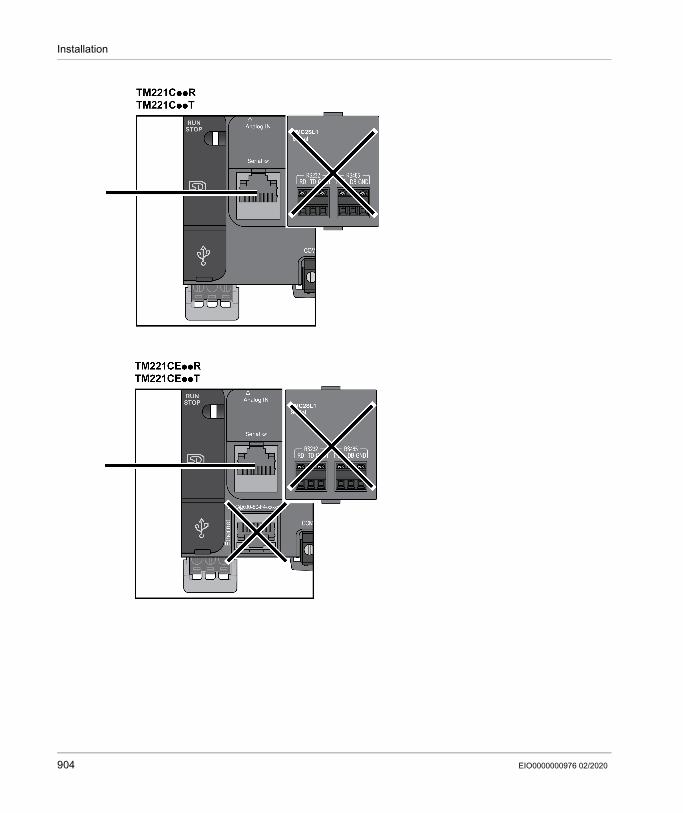
Installation
904 EIO0000000976 02/2020

Installation
EIO0000000976 02/2020 905

Installation
Pin AssignmentThis illustration presents the pin assignment of the RJ45 connector:
GroundingThe grounding lug of the Remote Graphic Display must be connected to the ground terminal screw of the cabinet.This table presents the characteristics of the grounding connection:
Pin Signal Description1 N.C. No connection2 N.C. No connection3 N.C. No connection4 D1 Modbus SL: D1 (+/B) RS-485 2-wire5 D0 Modbus SL: D0 (-/A) RS-485 2-wire6 N.C. No connection7 5 Vdc Power delivered by the logic controller8 0 Vdc -
WARNINGUNINTENDED EQUIPMENT OPERATIONDo not connect wires to unused terminals and/or terminals indicated as “No Connection (N.C.)”.Failure to follow these instructions can result in death, serious injury, or equipment damage.
Characteristic DescriptionMinimum wire gauge 2.5 mm² (AWG 14)Lug size 6.35 x 0.81 mm (0.25 x 0.032 in)Connection Female spade terminal (AMP 6392-1 or similar)
906 EIO0000000976 02/2020

Installation
Connecting CablesYou can use the following cable for connecting the Remote Graphic Display to the logic controller:
This illustration presents the internal wiring of the RJ45 connection:
Reference Description LengthXBTZ9980 Modbus serial link cable (2 RJ45 male connectors) 2.5 m (8.20 ft)VW3A1104R10 Modbus serial link cable (2 RJ45 male connectors) 1.0 m (3.28 ft)
1 No connection 12 No connection 23 No connection 34 D1 45 D0 56 No connection 67 5 Vdc 78 0 Vdc 8Shielding Shield Shielding
EIO0000000976 02/2020 907

Installation
WARNINGUNINTENDED EQUIPMENT OPERATIONDo not connect wires to unused terminals and/or terminals indicated as “No Connection (N.C.)”.Failure to follow these instructions can result in death, serious injury, or equipment damage.
908 EIO0000000976 02/2020

Installation
Updating the Firmware
PresentationFirmware updates can be downloaded to the Remote Graphic Display from the PC that is running EcoStruxure Machine Expert - Basic.For details, refer to Downloading Firmware to the Remote Graphic Display (see page 206).
EIO0000000976 02/2020 909

Installation
910 EIO0000000976 02/2020

Modicon M221How to Use the DisplayEIO0000000976 02/2020
How to Use the Remote Graphic Display
Chapter 15How to Use the Remote Graphic Display
IntroductionThis chapter provides information related to the graphic screen presentations, the navigation, and the password protection of the Remote Graphic Display.
What Is in This Chapter?This chapter contains the following topics:
Topic PageDescription 912Navigation 913Password Protection 915
EIO0000000976 02/2020 911

How to Use the Display
Description
Graphic Screen DescriptionThis is a graphic screen example of the Remote Graphic Display:
This table describes the areas of the graphic screen:
Home PageAfter connecting the Remote Graphic Display, it displays the home page that has been chosen in EcoStruxure Machine Expert - Basic (see page 929).The default home page is the Setup Menu that allows you to configure and monitor the general parameters of your logic controller (see page 917).
Item Name Label Description1 Header Alarm Informs you that at least 1 alarm is active on the Alarm View
page (see page 923).NOTE: This field is empty if no alarm is active or if no Alarm View (see page 952) page has been defined.
Page title –Date and time –
2 Menus or Pages – Menus, submenus, parameters, values, or other content are displayed in scrolling window format on five displayed lines.
3 Footer R1 to R4 Labels corresponding to actions if configured at a page level. For more information, refer to Actions (see page 949).
912 EIO0000000976 02/2020

How to Use the Display
Navigation
OverviewThis table describes the navigation controls of the Remote Graphic Display:
Name Function CommentF1 key Executes actions defined with EcoStruxure Machine
Expert - Basic for that key.For more information, refer to Actions (see page 949).
MOD key Moves to the next selectable object. In a page with a scroll bar, this key is disabled.ESC key Goes back to the previous page. You can go back up to 12 pages.R1 to R4 keys Execute an action. The actions are either fixed, such as those
found in Setup pages, or defined/assigned with EcoStruxure Machine Expert - Basic for Operator Interface pages. For more information, refer to Actions (see page 949).
Home key Goes back to the Home page. For more information, refer to Home Page (see page 912).
Information key
Displays a contextual help page. The help pages are either fixed, such as those found in Setup pages, or defined/assigned with EcoStruxure Machine Expert - Basic for Operator Interface pages. For more information on help pages, refer to the Template Pages (see page 936).
F2 key Executes actions defined with EcoStruxure Machine Expert - Basic for that key.
For more information, refer to Actions (see page 949).
Touch wheelUp/down arrows
Depending on the page, it can either: Select the next/previous elements displayed Increment/decrement the selected object
–
Right/left arrows
Select the next/previous selectable object. In a page with a scroll bar, right/left arrows are disabled.
OK Opens a menu, submenu, or page. Enables modification for the numerical value of a
parameter.
For more information, refer to Edit Pages (see page 920).
NOTICEINOPERABLE EQUIPMENTDo not use hard or pointed objects to operate the device.Failure to follow these instructions can result in equipment damage.
EIO0000000976 02/2020 913

How to Use the Display
Access ProtectionThe access to some pages can be restricted by a password. For more information, refer to Password Protection (see page 915).
914 EIO0000000976 02/2020

How to Use the Display
Password Protection
OverviewYou can use EcoStruxure Machine Expert - Basic software to define a password. If enabled, this unique password helps to protect: the selected page(s) of the Operator Interface The Setup pages that can perform an action on the logic controller: Controller Setup Controller State Data Table Alarm Reset
For more information, refer to Set General Parameters (see page 934).
Password Management in the Remote Graphic DisplayWhen you try to access a protected page on the Remote Graphic Display, you need to enter the password:
If... Then ... CommentThe entered password is correct
You can consult the pages. The password is valid for 10 minutes or until you press the Home key.
The entered password is incorrect
An error message appears. When leaving the error page, you can enter the password again. If you cancel, the Home page is displayed.
EIO0000000976 02/2020 915

How to Use the Display
916 EIO0000000976 02/2020

Modicon M221Setup Menu FunctionalityEIO0000000976 02/2020
Setup Menu Functionality
Chapter 16Setup Menu Functionality
IntroductionThis chapter provides information related to the menus present in the Setup of the Remote Graphic Display.
What Is in This Chapter?This chapter contains the following topics:
Topic PageSetup Menu Presentation 918Controller Setup Menu 919Controller State Menu 921Alarm Menu 923Data Table Menu 925
EIO0000000976 02/2020 917

Setup Menu Functionality
Setup Menu Presentation
Menu StructureThis table lists the menu and submenus present in the Setup Menu of the Remote Graphic Display:
NOTE: Keeping the backlight ON continuously reduces the lifetime of the device.
Menu Submenu CommentController Information Device Name
Firmware VersionLast MAST cycleMin. MAST cycleMax. MAST cycle
–
Controller Setup Date and TimeSerial 2Ethernet
For more information, refer to the Controller Setup Menu (see page 919).
Display Setup LanguageContrastBacklight timeout
The language, the contrast and backlight timeout values are saved inside the Remote Graphic Display.The default backlight timeout is 10 minutes, it can be set from 0 (no timeout) to 10 minutes maximum.
Controller State – For more information, refer to the Controller State Menu (see page 921).
Controller Status ApplicationBoot AppIO BusCartridge
Each status can have these values: OK Not OK
Alarm Menu ViewHistoryDelete History
For more information, refer to the Alarm Menu (see page 923).
Data Table – For more information, refer to the Data Table Menu (see page 925).
SD Card Information – It is a help page that explains how to transfer firmware, application, and post configuration from: The logic controller to the SD card The SD card to the logic controller
NOTICEINOPERABLE EQUIPMENTSet the Backlight timeout of the device between 1 and 10 minutes.Failure to follow these instructions can result in equipment damage.
918 EIO0000000976 02/2020

Setup Menu Functionality
Controller Setup Menu
OverviewThis table lists the submenus that are present in the Controller Setup menu of the Setup:
NOTE: For more information on how to modify the Serial 2 or Ethernet parameters, refer to Edit Pages (see page 920).
Submenu Function CommentDate and Time Allows you to set the logic controller
internal date and time.The format of date and time can only be configured in EcoStruxure Machine Expert - Basic. Refer to Set the General Parameters (see page 934).
Serial 2(depending on the logic controller reference)
Allows you to configure the Serial 2 parameters (1): Physical Medium Baud rate Parity Format Stop Bits Modbus Address Polarization
Serial 1 cannot be configured as it interrupts the ongoing communication with the Remote Graphic Display.
Ethernet(depending on the logic controller reference)
Allows you to configure the Ethernet parameter (1): IP Mode IP Address Mask Gateway Device Name
If the IP Address and Mask are incorrect, your logic controller is automatically configured with the default values.
(1) The entered parameters are saved into the Post Configuration file. The parameters are retained after a power cycle.
EIO0000000976 02/2020 919

Setup Menu Functionality
Edit PagesThis graphic presents the Edit IP page:
This procedure explains how to modify selected parameters in the Serial 2 and Ethernet submenus:
Step Action1 Select Setup → Controller Setup.2 Select Serial 2 or Ethernet.
Result: The Serial 2 or Ethernet page is displayed.3 Select the parameter with the touch wheel and press OK to modify it.
Result: One of these pages is displayed: Edit Parameter Edit IP Edit Name
4 Select the digit using the MOD key or right/left arrows.5 Increment or decrement the selected digit using the touch wheel or up/down arrows. Turn the
touch wheel in the same direction for more than 2 seconds to accelerate the scrolling of digits.6 Press:
R1 (Valid) to apply the modification. R4 (Cancel) to discard the modification.
NOTE: Press the ESC key to discard the modification and go back to the previous page.
920 EIO0000000976 02/2020

Setup Menu Functionality
Controller State Menu
OverviewThe Controller State menu allows you to see the present state of your logic controller and perform commands in the logic controller.
Remote Control ConsiderationsCare must be taken and provisions made for use of this product as a control device to avoid inadvertent consequences of commanded machine operation, state changes, or alteration of data memory or machine operating parameters.
WARNINGUNINTENDED EQUIPMENT OPERATION Place operator devices of the control system near the machine or in a place where you have
full view of the machine. Protect operator commands against unauthorized access. If remote control is a necessary design aspect of the application, ensure that there is a local,
competent, and qualified observer present when operating from a remote location. Configure and install the Run/Stop input, if so equipped, or, other external means within the
application, so that local control over the starting or stopping of the device can be maintained regardless of the remote commands sent to it.
Failure to follow these instructions can result in death, serious injury, or equipment damage.
WARNINGUNINTENDED MACHINE OR PROCESS START-UP Verify the state of security of your machine or process environment before applying power to
the Run/Stop input. Use the Run/Stop input to help prevent the unintentional start-up from a remote location.Failure to follow these instructions can result in death, serious injury, or equipment damage.
EIO0000000976 02/2020 921

Setup Menu Functionality
Logic Controller CommandsThis procedure explains how to perform the logic controller commands:
For more information, refer to the Controller States and Behaviors part of your logic controller programming guide.
Step Action1 Select Setup → Controller State.2 Press:
R1 (Run) to start the logic controller R2 (Stop) to stop the logic controller R3 (Init) to initialize the logic controller
3 When a confirmation page is displayed, select Yes or No.4 Press:
R1 (Valid) R4 (Cancel)
922 EIO0000000976 02/2020

Setup Menu Functionality
Alarm Menu
OverviewThe Alarm Menu contains these submenus: View History Delete History
Alarm ViewThe Alarm View page displays the active alarms. Alarm messages are configured in EcoStruxure Machine Expert - Basic. For more information, refer to the alarm definition (see page 952).Alarms are associated with specific memory bits within the logic controller. Those bits are monitored and, when TRUE, are included in the Alarm View.
When system bit %S122 is set to 1, the Alarm View page is displayed automatically when a rising edge is detected on an alarm bit.When system bit %S123 is set to 1, the backlight on the Remote Graphic Display turns red when an alarm is active. For more information, refer to system bit (%S122 and %S123) description (see page 242).NOTE: Alarm bit must be ON for at least 50 ms before it is included in the Alarm View .
Alarm History
The History page displays a maximum of 40 alarm messages with the date and time when the alarm either became active or was resolved, along with an up arrow to indicate when the alarm became active and a down arrow when it is resolved. The most recent alarm is at the top of the list.
EIO0000000976 02/2020 923

Setup Menu Functionality
Alarm ResetThe Alarm Reset page is used to clear the alarm history:
Step Action1 Select Setup → Alarm Menu → Delete History.
Result: The Alarm Reset page is opened.2 Press R1 (Delete) to clear the alarm history.
Result: The Alarm History page is empty.
924 EIO0000000976 02/2020

Setup Menu Functionality
Data Table Menu
OverviewIn the Data Table page, you can add/delete or modify the value of a variable: Memory objects System objects I/O objectsA maximum of 20 entries is displayed in this page.NOTE: This table is not saved after a power cycle of your logic controller.
Remote Control ConsiderationsCare must be taken and provisions made for use of this product as a control device to avoid inadvertent consequences of commanded machine operation, state changes, or alteration of data memory or machine operating parameters.
Object TypesThese memory objects are available: System bit (%S) System word (%SW) Memory bit (%M) Memory word (%MW) Constant word (%KW) Memory double word (%MD)These I/O objects are available: Input bit (%I) Output bit (%Q) Input word (%IW)
WARNINGUNINTENDED EQUIPMENT OPERATION Place operator devices of the control system near the machine or in a place where you have
full view of the machine. Protect operator commands against unauthorized access. If remote control is a necessary design aspect of the application, ensure that there is a local,
competent, and qualified observer present when operating from a remote location. Configure and install the Run/Stop input, if so equipped, or, other external means within the
application, so that local control over the starting or stopping of the device can be maintained regardless of the remote commands sent to it.
Failure to follow these instructions can result in death, serious injury, or equipment damage.
EIO0000000976 02/2020 925

Setup Menu Functionality
Output word (%QW) Input status word (%IWS) Output status word (%QWS)
Add/Delete a VariableThis procedure explains how to add a variable in the Data Table page:
NOTE: You can delete a variable from the table by pressing R2 (Delete).
Edit a VariableYou can modify the value of an existing variable.NOTE: Editing a variable is not allowed when the logic controller state is EMPTY.
Follow the procedures below when editing: A word or double word variable A memory bit variable An I/O bit variable
Step Action1 Select Setup → Data Table.2 Press R1 (Add).
Result: The Object Type page is displayed.3 Select the object types.
For more information on object types, refer to the list (see page 925).4 Press R1 (Select).5 Enter:
The address for a memory object. The module and channel values for an I/O object.
6 Press R3 (Edit) or use the touch wheel.7 Select the displayed representation (Decimal or hexadecimal).8 Press R1 (Add) to add the variable in the data table.9 Repeat steps 2 to 8 to add another variable to your monitoring list.
926 EIO0000000976 02/2020

Setup Menu Functionality
Edit a Word or a Double Word VariableThis procedure explains how to modify the value of a word or a double word variable in the Data Table page:
Edit a Memory Bit VariableThis procedure explains how to modify the value of a memory bit variable in the Data Table page:
Step Action1 Select Setup → Data Table.2 Select the word or double word variable to modify.3 Press R3 (Edit) to modify the variable.
Result: The Edit Word or Edit DWord page is displayed.4 Select the digit using the MOD key or right/left arrows.5 Increment or decrement the selected digit using the touch wheel or up/down arrows.6 Press:
R1 (Apply) to apply the modification. R4 (Cancel) to discard the modification.
NOTE: Press the ESC key to discard the modification and go back to the previous page.
7 Repeat steps 2 to 6 to modify another word or double word variable.
Step Action1 Select Setup → Data Table.2 Select the memory bit variable to modify.3 Press R3 (Edit) to modify the variable.
Result: The Edit bit page is displayed.4 Select Off or On using the touch wheel or up/down arrows.5 Press:
R1 (Apply) to apply the modification. R4 (Cancel) to discard the modification.
NOTE: Press the ESC key to discard the modification and go back to the previous page.
6 Repeat steps 2 to 5 to modify another memory bit variable.
EIO0000000976 02/2020 927

Setup Menu Functionality
Edit an I/O Bit VariableForcing input and output values in a running logic controller can have serious consequences to the operation of a machine or process. Only those who understand the implications in the controlling logic, and who understand the consequences of forced I/O on the machine or process, should attempt to use this function.
This procedure explains how to modify the value of an I/O bit variable in the Data Table page:
WARNINGUNINTENDED EQUIPMENT OPERATIONYou must have prior knowledge of the process and the controlled equipment before attempting to force logic controller physical inputs/outputs, or writing values to logic controller memory locations.Failure to follow these instructions can result in death, serious injury, or equipment damage.
Step Action1 Select Setup → Data Table.2 Select the I/O bit variable to modify.3 Press R3 (Edit) to modify the variable.
Result: The Edit I/O bit page is displayed.4 Select Off or On using the touch wheel or up/down arrows.5 Press:
R1 (Apply) to apply the modification. R2 (Force) to force the I/O value. R3 (Unforce) to unforce the I/O value. R4 (Cancel) to discard the modification.
NOTE: Press the ESC key to discard the modification and go back to the previous page.
6 Repeat steps 2 to 5 to modify another I/O bit variable.
928 EIO0000000976 02/2020

Modicon M221Creating Operator InterfaceEIO0000000976 02/2020
Creating an Operator Interface with EcoStruxure Machine Expert - Basic
Chapter 17Creating an Operator Interface with EcoStruxure Machine Expert - Basic
IntroductionThis chapter provides information on how to build an Operator Interface in the Display tab of EcoStruxure Machine Expert - Basic.
What Is in This Chapter?This chapter contains the following topics:
Topic PagePrerequisite 930EcoStruxure Machine Expert - Basic Display Tab 932General Properties 934Add/Delete a Page 936Configure a Page 945Export/Import a Page 948Actions 949Alarm Definition 952
EIO0000000976 02/2020 929

Creating Operator Interface
Prerequisite
Serial Line ConfigurationTo configure the Serial/Serial 1 line in EcoStruxure Machine Expert - Basic:
Step Action1 Select the Configuration tab.2 Click the SL1 (Serial Line) node in the hardware tree.3 Select TMH2GDB in the Protocol field.
The Remote Graphic Display uses fixed serial line communication parameters:
4 Click Apply.Result: The serial line is configured to communicate with your Remote Graphic Display and the Display tab is activated.
5 Click the Display node that appears below the SL1 (Serial Line) node in the hardware tree to display device settings.
930 EIO0000000976 02/2020

Creating Operator Interface
This graphic presents the Device settings in the Configuration tab of EcoStruxure Machine Expert - Basic:
EIO0000000976 02/2020 931

Creating Operator Interface
EcoStruxure Machine Expert - Basic Display Tab
OverviewThe Operator Interface is a component of the application. For more information on creating projects, refer to Creating Projects With EcoStruxure Machine
Expert - Basic. For more information on transferring applications, refer to Downloading and Uploading
Applications.The Operator Interface is built with the Display tab in EcoStruxure Machine Expert - Basic:
1 Tree2 Buttons3 Visualization area4 Editable area
932 EIO0000000976 02/2020

Creating Operator Interface
Button DescriptionThe buttons apply to the pages of the Operator Interface:
Tree DescriptionThis table lists the menus and submenus present in the tree in the Display tab:
Button Menu FunctionAddPage Add a page (see page 936).
DeletePage Delete a customized page (see page 944).
ExportPage Export a page (see page 948).
ImportPage Import a page (see page 948).
Menu Submenu CommentMessages – If there is an error detected, a message is displayed.General Properties
F1 KeyF2 Key
To set the general parameters (see page 934).
Setup Alarm View To define a set of alarms (see page 952).Operator Interface
– To create customized menus, submenus and pages with the predefined templates (see page 936).
EIO0000000976 02/2020 933

Creating Operator Interface
General Properties
OverviewThe General Properties node allows you to set the general parameters of the Remote Graphic Display.
You may select time and date formats, the home page for the Operator Interface that you have defined, and the password used for the Remote Graphic Display. The password is effective in helping to protect the Operator pages that you have selected to be protected, and, if you choose, the Setup pages that affect the logic controller state and data.NOTE: The page defined as the home page cannot be protected by password. Setting a page protected by password as the home page automatically removes its password protection.A password, randomly selected, is automatically assigned as a default every time you create a new application. In addition, the Password protect Setup option is selected by default.
Set General PropertiesThis procedure explains how to set the general properties of the Display tab:
Step Action Comments1 Select the General Properties node in the tree. –2 Select the date format in the Date format field. The date and time formats are used in the
standard header and in the alarm history.3 Select the time format in the Time format field.4 Enter a password to protect the selected Operator
Interface pages and, optionally, the Setup.NOTE: You may change the default password, or unselect the optional Setup protection.For more information, refer to Password Protection (see page 915).
5 Activate the Password protect Setup check box to use the password to protect the Setup.
6 Select the home page. The home page is the first page displayed once your application has been downloaded into the controller and also when you press the Home button on the Remote Graphic Display.
The Setup menu page is selected by default. Any other operator interface pages you have created can also be selected. For more information, refer to Add a page (see page 936).
934 EIO0000000976 02/2020

Creating Operator Interface
F1 and F2 Key AssignmentsThis procedure explains how to assign actions to F1 Key and F2 Key:
Step Action1 Select the F1 Key or F2 Key node in the tree.2 Select the Action type that you want to associate with the key. For more information, refer to
Action (see page 949).
EIO0000000976 02/2020 935

Creating Operator Interface
Add/Delete a Page
OverviewTo build your Operator Interface, you need to create pages in the Display tab by using templates.
Add a PageThis table explains how to add a page in the Operator Interface:
Menu TemplateA menu page allows the user to navigate between several pages.The user can press Select (R1) button to display the selected page.To configure a menu page:
Step Action1
Click the (AddPage) button.Result: The Select a page template window is displayed.
2 Select the template page: Menu template (see page 936) Monitor template (see page 937) Control table template (see page 938) Bargraph template (see page 939) Double bargraph template (see page 940) VU meter template (see page 942) Toggle control table template (see page 943)
3 Click Ok to validate.Result: The page is added in the tree (see page 933).
4 Configure the properties of the page as described in Configure a page (see page 945).5 Repeat steps 1 to 3 to add another page in your Operator Interface.
Step Action1 Select the Elements node in the tree.2 Enter the text to display.3 Select a Destination page.4 Click Add.5 Repeat steps 2 to 4 to configure other destination pages. You can add a maximum of 30
elements to the page.6 Configure the R2, R3, and R4 Key assignments (see page 947).
936 EIO0000000976 02/2020

Creating Operator Interface
TMH2GDB example:
Elements node in EcoStruxure Machine Expert - Basic example:
Monitor TemplateA monitor page allows the user to monitor memory or I/O variables.If the Write access is activated, the user can press Edit (R1) button to modify the selected variable value.To configure the monitor page:
Step Action1 Select the Elements node in the tree.2 Enter the text to display.3 Enter the variable to monitor.
Refer to the available variable type (see page 945) or refer to the text that is displayed when the pointer is on Variable.
4 Click Add.5 On the created line, activate the Write access check box to allow the user to modify the variable
value.6 Repeat steps 2 to 5 to configure other variables to monitor. You can add a maximum of 30
elements to the page.7 Configure the R2, R3, and R4 Key assignments (see page 947).
EIO0000000976 02/2020 937

Creating Operator Interface
TMH2GDB view:
Elements node in EcoStruxure Machine Expert - Basic example:
Control Table TemplateA control page allows the user to control memory or I/O bit values.This page allows you to associate a text string to each bit value.If the Write access is activated, the user can press On (R1) or Off (R2) buttons to change the selected bit value.To configure the control page:
Step Action1 Select the Elements node in the tree.2 Enter the variable to control.
Refer to the available variable type (see page 945) or refer to the text that is displayed when the pointer is on Variable.
3 Enter the Text when value is TRUE.4 Enter the Text when value is FALSE.5 Click Add.6 On the created line, activate the Write access check box to allow the user to modify the variable
value.
938 EIO0000000976 02/2020

Creating Operator Interface
TMH2GDB view:
Elements node in EcoStruxure Machine Expert - Basic example:
Bargraph TemplateA bargraph page allows the user to control a memory or I/O variable value with a bargraph representation of the variable value.If the Write access is activated, the user can press Edit (R1) button to change the value.To configure the bargraph page:
7 Repeat steps 2 to 6 to configure other variables to monitor. You can add a maximum of 30 elements to the page.
8 Configure the R3 and R4 Key assignments (see page 947).
Step Action
Step Action1 Select the Elements node in the tree.2 Enter the variable to control.
Refer to the available variable type (see page 945) or refer to the text that is displayed when the pointer is on Variable.
3 Enter the Unit.4 Enter the Minimum scale value.5 Enter the Maximum scale value.
EIO0000000976 02/2020 939

Creating Operator Interface
TMH2GDB view:
Elements node in EcoStruxure Machine Expert - Basic example:
Double Bargraph TemplateA double bargraph page allows the user to control 2 memory or I/O variables value with a bar graph representation for each variable value.If the Write access is activated, the user can edit the BarGraph1 variable with the Edit.1 (R1) button and the BarGraph2 variable with Edit.2 (R2) To configure the double bargraph page:
6 Activate the Write access check box to allow the user to modify the variable value.7 Configure the R2, R3, and R4 Key assignments (see page 947).
Step Action
Step Action1 Select the Elements node in the tree.2 Enter the variable to control.
Refer to the available variable type (see page 945) or refer to the text that is displayed when the pointer is on Variable.
3 Enter the Unit.4 Enter the Minimum scale value.
940 EIO0000000976 02/2020

Creating Operator Interface
TMH2GDB view:
Elements node in EcoStruxure Machine Expert - Basic example:
5 Enter the Maximum scale value.6 Activate the Write access check box to allow the user to modify the variable value.7 Repeat steps 2 to 6 to configure the second variable. You can add a maximum of 30 elements
to the page.8 Configure the R3 and R4 Key assignments (see page 947).
Step Action
EIO0000000976 02/2020 941

Creating Operator Interface
VU Meter TemplateA VU meter page allows the user to control a memory or I/O variable value with a VU meter representation of the variable value.If the Write access is activated, the user can press Edit (R1) button to change the value.To configure the VU meter page:
TMH2GDB view:
Elements node in EcoStruxure Machine Expert - Basic example:
Step Action1 Select the Elements node in the tree.2 Enter the variable to control.
Refer to the available variable type (see page 945) or refer to the text that is displayed when the pointer is on Variable.
3 Enter the Unit.4 Enter the Minimum scale value.5 Enter the Maximum scale value.6 Activate the Write access check box to allow the user to modify the variable value.7 Configure the R2, R3, and R4 Key assignments (see page 947).
942 EIO0000000976 02/2020

Creating Operator Interface
Toggle Control Table TemplateA toggle control page allows the user to control memory or I/O bit value.This page allows you to associate a text string to each bit value.If the Write access is activated, the user can press Not (R1) button to toggle the selected bit (TRUE to FALSE or FALSE to TRUE).To configure the toggle control page:
TMH2GDB view:
Elements node in EcoStruxure Machine Expert - Basic example:
Step Action1 Select the Elements node in the tree.2 Enter the variable to control.
Refer to the available variable type (see page 945) or refer to the text that is displayed when the pointer is on Variable.
3 Enter the Text when value is TRUE.4 Enter the Text when value is FALSE.5 Click Add.6 On the created line, activate the Write access check box to allow the user to modify the variable
value.7 Repeat steps 2 to 6 to configure other variables to control. You can add a maximum of 30
elements to the page.8 Configure the R2, R3, and R4 Key assignments (see page 947).
EIO0000000976 02/2020 943

Creating Operator Interface
Delete a PageThis table explains how to delete a page in the Display tab:
Step Action1 Click the page that you want to delete under the Operator Interface node in the tree.2
Click the (Delete Page) button, or right-click and choose Delete page.Result: A confirmation window appears.
3 Click Yes.Result: The page is deleted.
944 EIO0000000976 02/2020

Creating Operator Interface
Configure a Page
OverviewIn the tree, the added page is represented as follows: Page ID Elements R1 key (if available) R2 key (if available) R3 key R4 key (if available)
Page PropertiesThis procedure explains how to define the Page properties:
The Page index displayed is automatically generated by EcoStruxure Machine Expert - Basic and can be written in a user program to display the page, or read in a user program to detect the page currently being displayed.For more information, refer to system word (%SW184) description (see page 254).
ElementsThe configuration of elements depends on the template.Enter customized text and/or appropriate values according to each template. For more information, refer to Template Pages (see page 936).You can add a maximum of 30 elements to a page.
Step Action Comment1 Click the page ID node in the tree.
Result: The Page properties appear.You can rename the page ID by double-clicking or right-clicking and choosing Rename page.
2 Enter a page title in the Title field. –3 Enter a help text in the Help text field if needed. The help text is displayed when pressing the
Information key on the Remote Graphic Display. (1)
4 Activate/deactivate the Password protect check box to protect this page with the password or to exclude this page from the protection.
For more information, refer to Password Protection (see page 915).
(1) If no text is entered, the Information key has no effect on this page.
EIO0000000976 02/2020 945

Creating Operator Interface
This table describes the object types that can be entered in the Variable, Unit, Minimum, and Maximum fields for the template:
Fill in the fields following the rules described in Language Objects.
%I %Q %IW %QW %IWS %QWS %M or %MWi.Xk
%S %MW %KW %MD %SW Nu-meric value
Text
Variable/Variable1Monitor x x x x x x x x x x x x – –Control table
x x – – – – x x – – – – – –
Toggle Control table
x x – – – – x x – – – – – –
Bargraph – – x x – – – – x – x x – –Double Bargraph
– – x x – – – – x – x x – –
VU meter – – x x – – – – x – x x – –Variable/Variable2Double Bargraph
– – x x – – – – x – x x – –
UnitBargraph – – – – – – – – – – – – – xDouble Bargraph
– – – – – – – – – – – – – x
VU meter – – – – – – – – – – – – – xMinimum/MaximumBargraph – – – – – – – – – – – – x –Double Bargraph
– – – – – – – – – – – – x –
VU meter – – – – – – – – – – – – x –
946 EIO0000000976 02/2020

Creating Operator Interface
R1, R2, R3, and R4 Key AssignmentsWhen a key appears in the tree, you can assign an action and a label to it:
NOTE: The templates have a key configured by default to go to the Alarm View page. You can choose to change the default action and the label of this key.
Step Action1 Select the key node in the tree.2 Select the Action type that you want to associate with the key. For more information, refer to
action (see page 949).3 You can optionally rename the default label that is displayed above the corresponding key of the
Remote Graphic Display. To do so, double-click the node or right-click and choose Rename.
EIO0000000976 02/2020 947

Creating Operator Interface
Export/Import a Page
OverviewAny page of the Operator Interface can be: Exported to the PC Imported from the PC
Export a Page
To export a page, click the (ExportPage) button.The page is saved in a specific format on your PC.
Import a Page
To import a page, click the (ImportPage) button.The page can then be imported in the same application, or in another application, with EcoStruxure Machine Expert - Basic.
948 EIO0000000976 02/2020

Creating Operator Interface
Actions
OverviewAn action can be associated to some keys: R1, R2, R3, or R4 Key (when available) for each page. Refer to R1, R2, R3, and R4 Key
Assignments (see page 947). F1 Key or F2 Key for all the pages. Refer to F1 and F2 Key Assignments (see page 935).The action is executed when pressing the keys.
Defining ActionsThere are two types of actions: Function Navigation
FunctionForcing input and output values in a running logic controller can have serious consequences to the operation of a machine or process. Only those who understand the implications in the controlling logic, and who understand the consequences of forced I/O on the machine or process, should attempt to use this function.
These functions are available: WRITE_VALUE FORCE UNFORCE INCREMENT NOT
WARNINGUNINTENDED EQUIPMENT OPERATIONYou must have prior knowledge of the process and the controlled equipment before attempting to force logic controller physical inputs/outputs, or writing values to logic controller memory locations.Failure to follow these instructions can result in death, serious injury, or equipment damage.
EIO0000000976 02/2020 949

Creating Operator Interface
This graphic presents an example of a function in the Display tab:
Function Object TypesThis table describes the object types that can be entered in the Variable, Value, Increment Step, Minimum and Maximum fields for the functions, when appropriate:
Fill in the fields following the rules described in the part Language Objects.
%I %Q %IW %QW %IWS %QWS
%M or %MWi.Xk
%S %MW %KW %MD %SW Nu-meric value
Text
VariableWRITE_VALUE
– x – x – – x x x – x x – –
FORCE x x – – – – – – – – – – – –UNFORCE x x – – – – – – – – – – – –INCREMENT – – – x – – – – x – x – – –NOT – x – – – – x x – – – – – –ValueWRITE_VALUE
x x x x x x x x x x x x x –
Increment StepINCREMENT – – – – – – – – x – – – x –Minimum/MaximumINCREMENT – – – – – – – – – – – – x –
950 EIO0000000976 02/2020

Creating Operator Interface
NavigationThe Navigation action allows you to go to another page.In a dropdown list, you can choose a Destination page that corresponds to: Any page defined in your Operator Interface A page from the Setup
EIO0000000976 02/2020 951

Creating Operator Interface
Alarm Definition
OverviewThe Alarm View page allows you to define a customized set of alarm messages associated with memory or I/O bits. The text of the alarm is then displayed on the Remote Graphic Display when a rising edge of the associated bit is detected. You can define a maximum of 20 alarm messages.For more information on the alarm in the Remote Graphic Display, refer to the Alarm Menu (see page 923).Alarms have to be first configured in the Alarm View > Elements page of the Display tab in EcoStruxure Machine Expert - Basic.
Alarm ConfigurationThis graphic presents the Alarm View > Elements page of the Display tab:
Enter customized Alarm text and Variable values.The object types that can be entered in the Variable field are: %I %Q %M %S %MWi.XkFill in the field following the rules described in the part Language Objects.
952 EIO0000000976 02/2020

Modicon M221TMC2 Cartridges Programming PartEIO0000000976 02/2020
TMC2 Cartridges Programming Part
Part VTMC2 Cartridges Programming Part
What Is in This Part?This part contains the following chapters:
Chapter Chapter Name Page18 I/O Configuration General Information 95519 TMC2 Standard Cartridges Configuration 96320 TMC2 Application Cartridges Configuration 97721 TMC2 Analog Cartridge Diagnostics 987
EIO0000000976 02/2020 953

TMC2 Cartridges Programming Part
954 EIO0000000976 02/2020

Modicon M221I/O Configuration General InformationEIO0000000976 02/2020
I/O Configuration General Information
Chapter 18I/O Configuration General Information
IntroductionThis chapter provides general information to help you configure TMC2 cartridges in EcoStruxure Machine Expert.
What Is in This Chapter?This chapter contains the following topics:
Topic PageI/O Configuration General Practices 956General Description 957Using Cartridges in a Configuration 958Configuring Cartridges 960
EIO0000000976 02/2020 955

I/O Configuration General Information
I/O Configuration General Practices
Match Software and Hardware ConfigurationThe I/O that may be embedded in your controller is independent of the I/O that you may have added in the form of I/O expansion. It is important that the logical I/O configuration within your program matches the physical I/O configuration of your installation. If you add or remove any physical I/O to or from the I/O expansion bus or, depending on the controller reference, to or from the controller (in the form of cartridges), then you must update your application configuration. This is also true for any field bus devices you may have in your installation. Otherwise, there is the potential that the expansion bus or field bus no longer function while the embedded I/O that may be present in your controller continues to operate.
WARNINGUNINTENDED EQUIPMENT OPERATIONUpdate the configuration of your program each time you add or delete any type of I/O expansions on your I/O bus, or you add or delete any devices on your field bus.Failure to follow these instructions can result in death, serious injury, or equipment damage.
956 EIO0000000976 02/2020

I/O Configuration General Information
General Description
IntroductionThe TMC2 cartridges connect to Modicon TM221C Logic Controllers to increase the number of I/Os or serial lines available on the controller. Cartridges can be either: Analog cartridges Serial line cartridges
Cartridge FeaturesThe following table describes the TMC2 cartridge features:
Reference DescriptionTMC2AI2 (see page 964)
TMC2 cartridge with 2 analog voltage or current inputs (0...10 V, 0...20 mA, 4...20 mA), 12 bits
TMC2TI2 (see page 966)
TMC2 cartridge with 2 analog temperature inputs (thermocouple, RTD), 14 bits
TMC2AQ2V (see page 969)
TMC2 cartridge with 2 analog voltage outputs (0...10 V), 12 bits
TMC2AQ2C (see page 970)
TMC2 cartridge with 2 analog current outputs (4...20 mA), 12 bits
TMC2SL1 (see page 971)
TMC2 cartridge with 1 serial line (RS232 or RS485)
TMC2HOIS01 (see page 978)
TMC2 application cartridge with 2 analog voltage or current inputs for hoisting load cells
TMC2PACK01 (see page 980)
TMC2 application cartridge with 2 analog voltage or current inputs for packaging
TMC2CONV01 (see page 982)
TMC2 application cartridge with 1 serial line for conveying
EIO0000000976 02/2020 957

I/O Configuration General Information
Using Cartridges in a Configuration
Adding a CartridgeTMC2 cartridges can be connected to Modicon TM221C Logic Controller with 1 or 2 cartridge slots.NOTE: It is not possible to add 2 serial line cartridges to the same logic controller. For more information on cartridge compatibility with specific controllers, refer to the Hardware Guide of your logic controller. The following steps explain how to add a cartridge to a logic controller in an EcoStruxure Machine Expert - Basic configuration:
Replacing an Existing CartridgeTo replace an existing cartridge with a difference reference, drag and drop the new cartridge onto the cartridge to be replaced.A message appears asking you to confirm the operation. Click Yes to continue.
Step Description Result1 Click the Configuration tab in the EcoStruxure
Machine Expert - Basic window.–
2 In the hardware catalog area of the window, select M221 Cartridges.
–
3 Select a cartridge reference. A description of the physical characteristics of the selected cartridge appears in the bottom right-hand corner of the EcoStruxure Machine Expert - Basic window.
4 Drag and drop the cartridge onto an empty cartridge slot of a Modicon TM221C Logic Controller logic controller.
The cartridge is added to the MyController → IO Bus area of the device tree.For serial line cartridges, the SL2 (Serial line) node appears. For analog cartridges, the Analog inputs or Analog outputs subnode appears immediately below the cartridge reference.The following information about the selected cartridge is displayed in the lower central area of the EcoStruxure Machine Expert - Basic window: Information about the current status of the
cartridge. For application cartridges, a list of project
templates available for the cartridge.
958 EIO0000000976 02/2020

I/O Configuration General Information
Removing a CartridgeTo remove a cartridge from a controller, either click on the cartridge and press the Delete key, or right-click on the cartridge and click Remove on the contextual menu that appears. If the cartridge contains at least one address being used in the user logic of the program, a message appears asking you to confirm the operation. Click Yes to continue.
EIO0000000976 02/2020 959

I/O Configuration General Information
Configuring Cartridges
OverviewYou can configure cartridges on: The Configuration tab The Programming tab
Displaying Configuration DetailsThe Configuration tab allows you to configure cartridge modules.The steps below describe how to view the configuration of digital inputs on the Configuration tab:
Step Description1 Select the Configuration tab.2 For analog cartridges, select Cartridge 1 or Cartridge 2 in the device tree on the left of the
EcoStruxure Machine Expert - Basic window then click on the Analog inputs or Analog outputs subnode.For serial line cartridges, select SL2 (Serial line) in the device tree on the left of the EcoStruxure Machine Expert - Basic window The properties of the selected cartridge are displayed.
3 Refer to TMC2 Standard Cartridges Configuration (see page 963) or TMC2 Application Cartridges Configuration (see page 977) for configuration details.
960 EIO0000000976 02/2020

I/O Configuration General Information
Displaying Programming Properties The Programming tab allows you to configure programming-related properties of analog cartridges, such as symbols and comments.To display analog cartridge properties in the Programming tab:
Step Description1 Select the Programming tab.2 Click Tools → I/O objects → Analog inputs or Tools → I/O objects → Analog outputs
A list of I/O addresses appears in the lower central area of the EcoStruxure Machine Expert - Basic window.
3 Scroll down to the range of addresses corresponding to the cartridge you are configuring. The following properties are displayed: Used. Whether the address is being used in your program Address. The analog input or analog output address. Refer to I/O Addressing for details. Symbol. An optional symbol associated with the address.
Double-click in the Symbol column and type the name of a symbol to associate with this input.If a symbol already exists, right-click in the Symbol column and choose Search and Replace to find and replace occurrences of this symbol in the application.
Comment. An optional comment associated with the address.Double-click in the Comment column and type a comment to associate with this address.
EIO0000000976 02/2020 961

I/O Configuration General Information
962 EIO0000000976 02/2020

Modicon M221TMC2 Standard Cartridges ConfigurationEIO0000000976 02/2020
TMC2 Standard Cartridges Configuration
Chapter 19TMC2 Standard Cartridges Configuration
IntroductionThis chapter describes how to configure the TMC2 standard cartridges.
What Is in This Chapter?This chapter contains the following topics:
Topic PageTMC2AI2 964TMC2TI2 966TMC2AQ2V 969TMC2AQ2C 970TMC2SL1 971
EIO0000000976 02/2020 963

TMC2 Standard Cartridges Configuration
TMC2AI2
IntroductionThe TMC2AI2 is a standard cartridge featuring 2 analog voltage or current input channels with 12-bit resolution.The channel input types are: 0...10 V 0...20 mA 4...20 mAFor further hardware information, refer to TMC2AI2 (see page 1012).If you have physically wired the analog channel for a voltage signal and you configure the channel for a current signal in EcoStruxure Machine Expert - Basic, you may damage the analog circuit.
NOTICEINOPERABLE EQUIPMENTVerify that the physical wiring of the analog circuit is compatible with the software configuration for the analog channel.Failure to follow these instructions can result in equipment damage.
964 EIO0000000976 02/2020
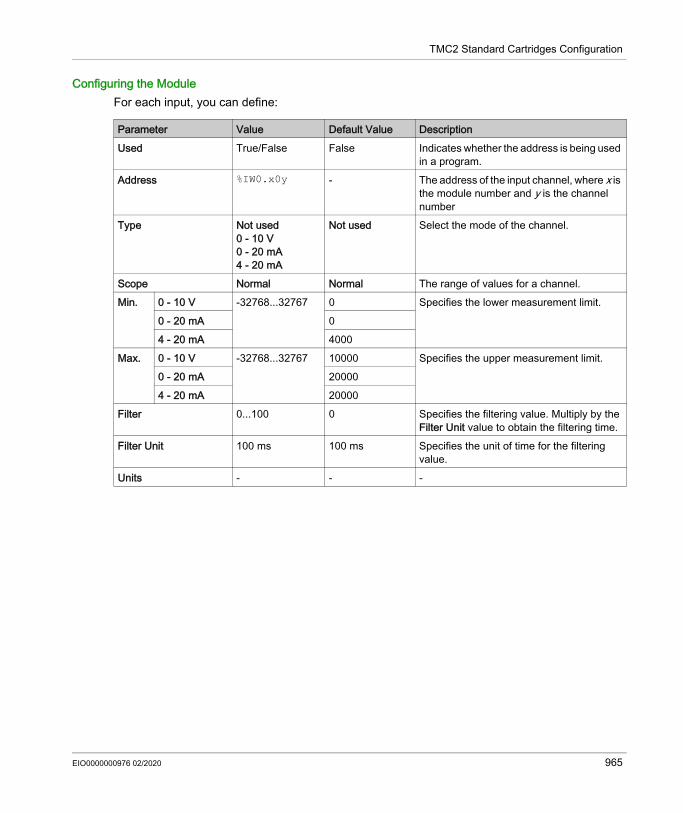
TMC2 Standard Cartridges Configuration
Configuring the ModuleFor each input, you can define:
Parameter Value Default Value DescriptionUsed True/False False Indicates whether the address is being used
in a program.Address %IW0.x0y - The address of the input channel, where x is
the module number and y is the channel number
Type Not used0 - 10 V0 - 20 mA4 - 20 mA
Not used Select the mode of the channel.
Scope Normal Normal The range of values for a channel.Min. 0 - 10 V -32768...32767 0 Specifies the lower measurement limit.
0 - 20 mA 04 - 20 mA 4000
Max. 0 - 10 V -32768...32767 10000 Specifies the upper measurement limit.0 - 20 mA 200004 - 20 mA 20000
Filter 0...100 0 Specifies the filtering value. Multiply by the Filter Unit value to obtain the filtering time.
Filter Unit 100 ms 100 ms Specifies the unit of time for the filtering value.
Units - - -
EIO0000000976 02/2020 965

TMC2 Standard Cartridges Configuration
TMC2TI2
IntroductionThe TMC2TI2 is a standard cartridge featuring 2 analog input channels with 14-bit resolution.The channel input types are: K Thermocouple J Thermocouple R Thermocouple S Thermocouple B Thermocouple E Thermocouple T Thermocouple N Thermocouple C Thermocouple PT100 PT1000 NI100 NI1000For further hardware information, refer to TMC2TI2 (see page 1017).If you have physically wired the analog channel for a voltage signal and you configure the channel for a current signal in EcoStruxure Machine Expert - Basic, you may damage the analog circuit.
NOTICEINOPERABLE EQUIPMENTVerify that the physical wiring of the analog circuit is compatible with the software configuration for the analog channel.Failure to follow these instructions can result in equipment damage.
966 EIO0000000976 02/2020

TMC2 Standard Cartridges Configuration
Configuring the ModuleFor each input, you can define:
Parameter Value Default Value DescriptionUsed True/False False Indicates whether the address is being
used in a program.Address %IW0.x0y - The address of the input channel, where
x is the module number and y is the channel number
Type K ThermocoupleJ ThermocoupleR ThermocoupleS ThermocoupleB ThermocoupleE ThermocoupleT ThermocoupleN ThermocoupleC ThermocouplePT100PT1000NI100NI1000
K Thermocouple Choose the mode of the channel.
Scope NormalCelsius (0.1°C)Fahrenheit (0.1°F) (except Thermocouple B and C)Fahrenheit (0.2°F) (for Thermocouple B and C only)
Normal Choose the temperature units for a channel.
Min. Temperature See the table below Specifies the lower measurement limit.Max. Temperature See the table below Specifies the upper measurement limit.Filter 0...100 0 Specifies the filtering value. Multiply by
the Filter Unit value to obtain the filtering time.
Filter Unit 100 ms 100 ms Specifies the unit of time for the filtering value.
Units See the table below Displays the temperature unit configured.
EIO0000000976 02/2020 967

TMC2 Standard Cartridges Configuration
Type Customized Celsius FahrenheitMin. Max. Min. Max. Units Min. Max. Units
K Thermocouple -32768 32767 -2000 13000 0.1 °C -3280 23720 0.1 °FJ Thermocouple -32768 32767 -2000 10000 0.1 °C -3280 18320 0.1 °FR Thermocouple -32768 32767 0 17600 0.1 °C 320 32000 0.1 °FS Thermocouple -32768 32767 0 17600 0.1 °C 320 32000 0.1 °FB Thermocouple -32768 32767 0 18200 0.1 °C 160 16540 0.2 °FE Thermocouple -32768 32767 -2000 8000 0.1 °C -3280 14720 0.1 °FT Thermocouple -32768 32767 -2000 4000 0.1 °C -3280 7520 0.1 °FN Thermocouple -32768 32767 -2000 13000 0.1 °C -3280 23720 0.1 °FC Thermocouple -32768 32767 0 23150 0.1 °C 160 20995 0.2 °FPT100 -32768 32767 -2000 8500 0.1 °C -3280 15620 0.1 °FPT1000 -32768 32767 -2000 6000 0.1 °C -3280 11120 0.1 °FNI100 -32768 32767 -600 1800 0.1 °C -760 3560 0.1 °FNI1000 -32768 32767 -600 1800 0.1 °C -760 3560 0.1 °F
968 EIO0000000976 02/2020

TMC2 Standard Cartridges Configuration
TMC2AQ2V
IntroductionThe TMC2AQ2V is a standard cartridge featuring 2 analog voltage output channels with 12-bit resolution.The channel output types are: 0...10 VFor further hardware information, refer to TMC2AQ2V (see page 1023).If you have physically wired the analog channel for a voltage signal and you configure the channel for a current signal in EcoStruxure Machine Expert - Basic, you may damage the analog circuit.
Configuring the Cartridge ModuleFor each output, you can define:
NOTICEINOPERABLE EQUIPMENTVerify that the physical wiring of the analog circuit is compatible with the software configuration for the analog channel.Failure to follow these instructions can result in equipment damage.
Parameter Value Default Value DescriptionUsed True/False False Indicates whether the address is being used
in a program.Address %QW0.x0y - Shows the address of the output channel,
where x is the cartridge number and y is the channel number
Type 0 - 10 V 0 - 10 V The mode of the channel.Scope Normal Normal The range of values for a channel.Min. 0 - 10 V -32768...32767 0 Specifies the lower measurement limit.Max. 0 - 10 V -32768...32767 10000 Specifies the upper measurement limit.Fallback value Min....Max. 0 (Min. if 0 is not
in the range)Specifies the fallback value of the output channel.
Units - - -
EIO0000000976 02/2020 969

TMC2 Standard Cartridges Configuration
TMC2AQ2C
IntroductionThe TMC2AQ2C is a standard cartridge featuring 2 analog current output channels with 12-bit resolution.The channel output types are: 4...20 mAFor further hardware information, refer to TMC2AQ2C (see page 1023).If you have physically wired the analog channel for a voltage signal and you configure the channel for a current signal in EcoStruxure Machine Expert - Basic, you may damage the analog circuit.
Configuring the Cartridge ModuleFor each output, you can define:
NOTICEINOPERABLE EQUIPMENTVerify that the physical wiring of the analog circuit is compatible with the software configuration for the analog channel.Failure to follow these instructions can result in equipment damage.
Parameter Value Default Value DescriptionUsed True/False False Indicates whether the address is being used
in a program.Address %QW0.x0y - Shows the address of the output channel,
where x is the cartridge number and y is the channel number
Type 4 - 20 mA 4 - 20 mA The mode of the channel.Scope Normal Normal The range of values for a channel.Min. 4 - 20 mA -32768...32767 4000 Specifies the lower measurement limit.Max. 4 - 20 mA -32768...32767 20000 Specifies the upper measurement limit.Fallback value Min....Max. 0 (Min. if 0 is not
in the range)Specifies the fallback value of the output channel.
Units - -
970 EIO0000000976 02/2020

TMC2 Standard Cartridges Configuration
TMC2SL1
IntroductionThe TMC2SL1 is a standard cartridge module featuring 1 serial line.For further hardware information, refer to TMC2SL1 (see page 1033).The serial line can be configured for any one of the following protocols: Modbus RTU Modbus ASCII ASCIIYou can configure both physical and protocol settings for the serial line. Serial lines are configured for the Modbus RTU protocol by default.NOTE: You can only add one serial line cartridge to the controller.
EIO0000000976 02/2020 971

TMC2 Standard Cartridges Configuration
Serial Line ConfigurationThis table describes how to configure the serial line:
Step Action1 Click the SL2 (Serial line) node in the Hardware Tree to display the serial line properties.
This figure shows the properties of the serial line for Modbus RTU and Modbus ASCII protocols:
This figure shows the properties of the serial line for ASCII protocol:
972 EIO0000000976 02/2020

TMC2 Standard Cartridges Configuration
This table describes each parameter of the serial line:
2 Edit the properties to configure the serial line.For detailed information on the serial line configuration parameters, refer to the table below.
Step Action
Parameter Editable Value Default Value DescriptionPhysical settingsBaud rate Yes 1200
240048009600192003840057600115200
19200 Allows you to select the data transmission rate (bits per second) for the modem from the drop-down list.
Parity Yes NoneEvenOdd
Even Allows you to select the parity of the transmitted data for error detection.Parity is a method of error detection in transmission.When parity is used with a serial port, an extra data bit is sent with each data character, arranged so that the number of 1 bits in each character, including the parity bit, is always odd or always even.If a byte is received with the wrong number of 1 bits, the byte is corrupt. However, an even number of detected errors can pass the parity check.
Data bits Yes(only for the ASCII protocol
78
7 for Modbus ASCII, 8 for Modbus RTU
Allows you to select the number of data bits from the drop-down list.The number of data bits in each character can be 7 (for true ASCII) or 8 (for any kind of data, as this matches the size of a byte). 8 data bits are almost universally used in all applications.
Stop bits Yes 12
1 Allows you to select the number of stop bits from the drop-down list.A stop bit is a bit indicating the end of a byte of data. For electronic devices, 1 stop bit is usually used. For slow devices like electromechanical teleprinters, 2 stop bits are used.
EIO0000000976 02/2020 973

TMC2 Standard Cartridges Configuration
Physical medium Yes RS485True/False
RS232True/False
RS485True
Allows you to select the physical medium for communication.You can only select either the RS485 or RS232 medium. Enabling one medium disables the other one.A physical medium in data communications is the transmission path over which a signal propagates. It is an interface for interconnection of devices with the logic controller.
Polarization Yes YesNo
No Polarization resistors are integrated in the cartridge module. Specify whether to switch on or off polarization.
Protocol settingsProtocol Yes Modbus RTU
Modbus ASCIIASCII
Modbus RTU Allows you to select the protocol transmission mode for communication from the drop-down list.Protocol advanced parameters are displayed based on the selected protocol. Refer to the following figures and tables.
Protocol settings for the Modbus RTU and Modbus ASCII protocols:Addressing Yes Slave
MasterSlave Allows you to select the addressing
mode. You can only select either of the Slave or Master addressing. Enabling one addressing mode disables the other one.
Address [1...247] Yes 1...247 1 Allows you to specify the address ID of the slave.
NOTE: This field is displayed only for the addressing of the slave. For master, this field does not appear on the screen.
Response time (x 100 ms)
Yes 10...255 ms 10 Allows you to specify the response time of the protocol to the queries.
Time between frames (ms)
Yes 3...255 ms 10 Allows you to specify the time between frames of the protocol.
Protocol settings for the ASCII protocol:
Parameter Editable Value Default Value Description
974 EIO0000000976 02/2020

TMC2 Standard Cartridges Configuration
Stop conditionResponse time (x 100 ms)
Yes 1...255 10 Allows you to specify the response time of the protocol to the queries.
Frame length received Yes 0...255 0 Allows you to specify the frame length received.
Frame received timeout (ms)
Yes 0...255 10 Allows you to specify the frame received timeout.
Frame structureStart character Yes 0...255 58 (if check box
is selected)Allows you to specify the start character of the frame.
First end character Yes 0...255 10 (if check box is selected)
Allows you to specify the first end character of the frame.
Second end character Yes 0...255 10 (if check box is selected)
Allows you to specify the second end character of the frame.
Send frame characters
Yes True/False False Allows you to enable or disable sending first end character of the frame to the ASCII protocol.
Parameter Editable Value Default Value Description
EIO0000000976 02/2020 975

TMC2 Standard Cartridges Configuration
976 EIO0000000976 02/2020

Modicon M221TMC2 Application Cartridges ConfigurationEIO0000000976 02/2020
TMC2 Application Cartridges Configuration
Chapter 20TMC2 Application Cartridges Configuration
IntroductionThis chapter describes how to configure the TMC2 application cartridges.
What Is in This Chapter?This chapter contains the following topics:
Topic PageTMC2HOIS01 978TMC2PACK01 980TMC2CONV01 982
EIO0000000976 02/2020 977

TMC2 Application Cartridges Configuration
TMC2HOIS01
IntroductionThe TMC2HOIS01 is an application cartridge module for hoisting, featuring 2 analog voltage or current input channels with 12-bit resolution.The channel input types are: 0...10 V 0...20 mA 4...20 mAFor further hardware information, refer to TMC2HOIS01 (see page 1040).If you have physically wired the analog channel for a voltage signal and you configure the channel for a current signal in EcoStruxure Machine Expert - Basic, you may damage the analog circuit.
NOTICEINOPERABLE EQUIPMENTVerify that the physical wiring of the analog circuit is compatible with the software configuration for the analog channel.Failure to follow these instructions can result in equipment damage.
978 EIO0000000976 02/2020

TMC2 Application Cartridges Configuration
Configuring the ModuleFor each input, you can define:
Parameter Value Default Value DescriptionUsed True/False False Indicates whether the address is being used
in a program.Address %IW0.x0y - The address of the input channel, where x is
the module number and y is the channel number
Type Not used0 - 10 V0 - 20 mA4 - 20 mA
Not used Choose the mode of the channel.
Scope Customized Customized The range of values for a channel.Min. 0 - 10 V -32768...32767 0 Specifies the lower measurement limit.
0 - 20 mA 04 - 20 mA 4000
Max. 0 - 10 V -32768...32767 10000 Specifies the upper measurement limit.0 - 20 mA 200004 - 20 mA 20000
Filter 0...100 0 Specifies the filtering value. Multiply by the Filter Unit value to obtain the filtering time.
Filter Unit 100 ms 100 ms Specifies the unit of time for the filtering value.
Units) - - -
EIO0000000976 02/2020 979

TMC2 Application Cartridges Configuration
TMC2PACK01
IntroductionThe TMC2PACK01 is an application cartridge module for packaging, featuring 2 analog voltage or current input channels with 12-bit resolution.The channel input types are: 0...10 V 0...20 mA 4...20 mAFor further hardware information, refer to TMC2PACK01 (see page 1045).If you have physically wired the analog channel for a voltage signal and you configure the channel for a current signal in EcoStruxure Machine Expert - Basic, you may damage the analog circuit.
NOTICEINOPERABLE EQUIPMENTVerify that the physical wiring of the analog circuit is compatible with the software configuration for the analog channel.Failure to follow these instructions can result in equipment damage.
980 EIO0000000976 02/2020

TMC2 Application Cartridges Configuration
Configuring the ModuleFor each input, you can define:
Parameter Value Default Value DescriptionUsed True/False False Indicates whether the address is being used
in a program.Address %IW0.x0y - The address of the input channel, where x is
the module number and y is the channel number
Type Not used0 - 10 V0 - 20 mA4 - 20 mA
Not used Choose the mode of the channel.
Scope Customized Customized The range of values for a channel.Min. 0 - 10 V -32768...32767 0 Specifies the lower measurement limit.
0 - 20 mA 04 - 20 mA 4000
Max. 0 - 10 V -32768...32767 10000 Specifies the upper measurement limit.0 - 20 mA 200004 - 20 mA 20000
Filter (x 100ms) 0...100 0 Specifies the filtering time (0...10 s).Units) - - -
EIO0000000976 02/2020 981

TMC2 Application Cartridges Configuration
TMC2CONV01
IntroductionThe TMC2CONV01 is an application cartridge module featuring 1 serial line for conveying.For further hardware information, refer to TMC2CONV01 (see page 1050).The serial line can be configured for any one of the following protocols: Modbus RTU Modbus ASCII ASCIIYou can configure both physical and protocol settings for the serial line. Serial lines are configured for the Modbus RTU protocol by default.NOTE: You can only add one serial line cartridge to the controller.
982 EIO0000000976 02/2020

TMC2 Application Cartridges Configuration
Serial Line ConfigurationThis table describes how to configure the serial line:
Step Action1 Click the SL2 (Serial line) node in the Hardware Tree to display the serial line properties.
This figure shows the properties of the serial line for Modbus RTU and Modbus ASCII protocols:
This figure shows the properties of the serial line for ASCII protocol:
EIO0000000976 02/2020 983

TMC2 Application Cartridges Configuration
This table describes each parameter of the serial line:
2 Edit the properties to configure the serial line.For detailed information on the serial line configuration parameters, refer to the table below.
Step Action
Parameter Editable Value Default Value DescriptionPhysical settingsBaud rate Yes 1200
240048009600192003840057600115200
19200 Allows you to select the data transmission rate (bits per second) for the modem from the drop-down list.
Parity Yes NoneEvenOdd
Even Allows you to select the parity of the transmitted data for error detection.Parity is a method of error detection in transmission.When parity is used with a serial port, an extra data bit is sent with each data character, arranged so that the number of 1 bits in each character, including the parity bit, is always odd or always even.If a byte is received with the wrong number of 1 bits, the byte is corrupt. However, an even number of detected errors can pass the parity check.
Data bits Yes(only for the ASCII protocol
78
7 for Modbus ASCII, 8 for Modbus RTU
Allows you to select the number of data bits from the drop-down list.The number of data bits in each character can be 7 (for true ASCII) or 8 (for any kind of data, as this matches the size of a byte). 8 data bits are almost universally used in all applications.
Stop bits Yes 12
1 Allows you to select the number of stop bits from the drop-down list.A stop bit is a bit indicating the end of a byte of data. For electronic devices, 1 stop bit is usually used. For slow devices like electromechanical teleprinters, 2 stop bits are used.
984 EIO0000000976 02/2020

TMC2 Application Cartridges Configuration
Physical medium Yes RS485True/False
RS232True/False
RS485True
Allows you to select the physical medium for communication.You can only select either the RS485 or RS232 medium. Enabling one medium disables the other one.A physical medium in data communications is the transmission path over which a signal propagates. It is an interface for interconnection of devices with the logic controller.
Polarization Yes YesNo
No Polarization resistors are integrated in the cartridge module. Specify whether to switch on or off polarization.
Protocol settingsProtocol Yes Modbus RTU
Modbus ASCIIASCII
Modbus RTU Allows you to select the protocol transmission mode for communication from the drop-down list.Protocol advanced parameters are displayed based on the selected protocol. Refer to the following figures and tables.
Protocol settings for the Modbus RTU and Modbus ASCII protocols:Addressing Yes Slave
MasterSlave Allows you to select the addressing
mode. You can only select either of the Slave or Master addressing. Enabling one addressing mode disables the other one.
Address [1...247] Yes 1...247 1 Allows you to specify the address ID of the slave.
NOTE: This field is displayed only for the addressing of the slave. For master, this field does not appear on the screen.
Response time (x 100 ms)
Yes 10...255 ms 10 Allows you to specify the response time of the protocol to the queries.
Time between frames (ms)
Yes 3...255 ms 10 Allows you to specify the time between frames of the protocol.
Protocol settings for the ASCII protocol:Stop conditionResponse time (x 100 ms)
Yes 1...255 10 Allows you to specify the response time of the protocol to the queries.
Parameter Editable Value Default Value Description
EIO0000000976 02/2020 985

TMC2 Application Cartridges Configuration
Frame length received Yes 0...255 0 Allows you to specify the frame length received.
Frame received timeout (ms)
Yes 0...255 10 Allows you to specify the frame received timeout.
Frame structureStart character Yes 0...255 58 (if check box
is selected)Allows you to specify the start character of the frame.
First end character Yes 0...255 10 (if check box is selected)
Allows you to specify the first end character of the frame.
Second end character Yes 0...255 10 (if check box is selected)
Allows you to specify the second end character of the frame.
Send frame characters
Yes True/False False Allows you to enable or disable sending first end character of the frame to the ASCII protocol.
Parameter Editable Value Default Value Description
986 EIO0000000976 02/2020

Modicon M221TMC2 Analog Cartridge DiagnosticsEIO0000000976 02/2020
TMC2 Analog Cartridge Diagnostics
Chapter 21TMC2 Analog Cartridge Diagnostics
TMC2 Analog Cartridge Diagnostics
IntroductionFor analog cartridges, the operating status of each I/O channel is given by the objects: %IWS0.x0y for input channel y of cartridge x %QWS0.x0y for output channel y of cartridge xThe real-time values of these objects can be read when in online mode, using either an animation table or the application.
Input Channel Status DescriptionThis table describes the possible values of the %IWS input channel status word:
Byte value Description0 Normal1 Data conversion in progress 2 Initialization 3 Input operation setting error or cartridge with no input4 Undefined5 Wiring error detected (input voltage/current high limit exceeded).6 Wiring error detected (input voltage/current low limit exceeded).7 Non-volatile memory error8...255 Undefined
EIO0000000976 02/2020 987

TMC2 Analog Cartridge Diagnostics
Output Channel Status DescriptionThis table describes the possible values of the %QWS output channel status word:
Byte value Description0 Normal1 Undefined2 Initialization3 Output operation setting error or cartridge with no output4 Undefined5 Undefined6 Undefined7 Non-volatile memory error8...255 Undefined
988 EIO0000000976 02/2020

Modicon M221TMC2 Cartridges Hardware PartEIO0000000976 02/2020
TMC2 Cartridges Hardware Part
Part VITMC2 Cartridges Hardware Part
What Is in This Part?This part contains the following chapters:
Chapter Chapter Name Page22 TMC2 Cartridges Description 99123 TMC2 Cartridges Installation 99324 TMC2 Standard Cartridges 101125 TMC2 Application Cartridges 1039
EIO0000000976 02/2020 989

TMC2 Cartridges Hardware Part
990 EIO0000000976 02/2020

Modicon M221TMC2 Cartridges DescriptionEIO0000000976 02/2020
TMC2 Cartridges Description
Chapter 22TMC2 Cartridges Description
General Description
IntroductionThe cartridges are designed to be connected to the Modicon TM221C Logic Controller range.
Cartridges FeaturesThe following table describes the TMC2 cartridges features:
Reference DescriptionTMC2AI2 (see page 1012)
TMC2 cartridge with 2 analog voltage or current inputs (0...10 V, 0...20 mA, 4...20 mA), 12 bits
TMC2TI2 (see page 1017)
TMC2 cartridge with 2 analog temperature inputs (thermocouple, RTD), 14 bits
TMC2AQ2V (see page 1023)
TMC2 cartridge with 2 analog voltage outputs (0...10 V), 12 bits
TMC2AQ2C (see page 1028)
TMC2 cartridge with 2 analog current outputs (4...20 mA), 12 bits
TMC2SL1 (see page 1033)
TMC2 cartridge with 1 serial line (RS232 or RS485)
TMC2HOIS01 (see page 1040)
TMC2 application cartridge with 2 analog voltage or current inputs for hoisting load cells
TMC2PACK01 (see page 1045)
TMC2 application cartridge with 2 analog voltage or current inputs for packaging
TMC2CONV01 (see page 1050)
TMC2 application cartridge with 1 serial line for conveying
EIO0000000976 02/2020 991

TMC2 Cartridges Description
Logic Controller CompatibilityNOTE: For more information on cartridge compatibility with specific controllers, refer to your controller-specific hardware guide.The following table describes the number of TMC2 cartridges that can be installed in a Modicon TM221C Logic Controller:
Reference Cartridge Slots Compatible Cartridges CombinationTMC2AI2TMC2TI2TMC2AQ2VTMC2AQ2CTMC2HOIS01TMC2PACK01
TMC2SL1TMC2CONV01
TM221C16RTM221CE16RTM221C16TTM221CE16TTM221C24RTM221CE24RTM221C24TTM221CE24T
1 1 00 1
TM221C40RTM221CE40RTM221C40TTM221CE40T
2 (1) 1 00 11 12 0
(1) Only one serial line cartridge (TMC2SL1, TMC2CONV01) may be added to a logic controller.
NOTICEELECTROSTATIC DISCHARGE Verify that empty cartridge slots have their covers in place before applying power to the
controller. Do not touch the contacts of the cartridge. Only handle the cartridge on the housing. Take the necessary protective measures against electrostatic discharges.Failure to follow these instructions can result in equipment damage.
992 EIO0000000976 02/2020

Modicon M221TMC2 Cartridges InstallationEIO0000000976 02/2020
TMC2 Cartridges Installation
Chapter 23TMC2 Cartridges Installation
What Is in This Chapter?This chapter contains the following sections:
Section Topic Page23.1 TMC2 General Rules for Implementing 99423.2 TMC2 Installation 99723.3 TMC2 Electrical Requirements 1006
EIO0000000976 02/2020 993

TMC2 Cartridges Installation
TMC2 General Rules for Implementing
Section 23.1TMC2 General Rules for Implementing
What Is in This Section?This section contains the following topics:
Topic PageEnvironmental Characteristics 995Certifications and Standards 996
994 EIO0000000976 02/2020

TMC2 Cartridges Installation
Environmental Characteristics
TMC2TMC2 cartridge environmental characteristics are the same as the Modicon TM221C Logic Controller (see page 579).
EIO0000000976 02/2020 995

TMC2 Cartridges Installation
Certifications and Standards
IntroductionFor more information, refer to Certifications and Standards (see page 582).
996 EIO0000000976 02/2020

TMC2 Cartridges Installation
TMC2 Installation
Section 23.2TMC2 Installation
What Is in This Section?This section contains the following topics:
Topic PageInstallation and Maintenance Requirements 998TMC2 Installation 1000
EIO0000000976 02/2020 997

TMC2 Cartridges Installation
Installation and Maintenance Requirements
Before StartingRead and understand this chapter before beginning the installation of your system.The use and application of the information contained herein require expertise in the design and programming of automated control systems. Only you, the user, machine builder or integrator, can be aware of all the conditions and factors present during installation and setup, operation, and maintenance of the machine or process, and can therefore determine the automation and associated equipment and the related safeties and interlocks which can be effectively and properly used. When selecting automation and control equipment, and any other related equipment or software, for a particular application, you must also consider any applicable local, regional or national standards and/or regulations.Pay particular attention in conforming to any safety information, different electrical requirements, and normative standards that would apply to your machine or process in the use of this equipment.
Disconnecting PowerAll options and modules should be assembled and installed before installing the control system on a mounting rail, onto a mounting plate or in a panel. Remove the control system from its mounting rail, mounting plate or panel before disassembling the equipment.
DANGERHAZARD OF ELECTRIC SHOCK, EXPLOSION OR ARC FLASH Disconnect all power from all equipment including connected devices prior to removing any
covers or doors, or installing or removing any accessories, hardware, cables, or wires except under the specific conditions specified in the appropriate hardware guide for this equipment.
Always use a properly rated voltage sensing device to confirm the power is off where and when indicated.
Replace and secure all covers, accessories, hardware, cables, and wires and confirm that a proper ground connection exists before applying power to the unit.
Use only the specified voltage when operating this equipment and any associated products.Failure to follow these instructions will result in death or serious injury.
998 EIO0000000976 02/2020

TMC2 Cartridges Installation
Programming Considerations
Operating EnvironmentIn addition to the Environmental Characteristics, refer to Product Related Information in the beginning of the present document for important information regarding installation in hazardous locations for this specific equipment.NOTE: For important safety information and the environment characteristics of the TMC2 cartridges, see the M221 Logic Controller Hardware Guide.
Installation Considerations
NOTE: JDYX2 or JDYX8 fuse types are UL-recognized and CSA approved.
WARNINGUNINTENDED EQUIPMENT OPERATION Only use software approved by Schneider Electric for use with this equipment. Update your application program every time you change the physical hardware configuration.Failure to follow these instructions can result in death, serious injury, or equipment damage.
WARNINGUNINTENDED EQUIPMENT OPERATION Use appropriate safety interlocks where personnel and/or equipment hazards exist. Install and operate this equipment in an enclosure appropriately rated for its intended
environment and secured by a keyed or tooled locking mechanism. Use the sensor and actuator power supplies only for supplying power to the sensors or
actuators connected to the module. Power line and output circuits must be wired and fused in compliance with local and national
regulatory requirements for the rated current and voltage of the particular equipment. Do not use this equipment in safety-critical machine functions unless the equipment is
otherwise designated as functional safety equipment and conforming to applicable regulations and standards.
Do not disassemble, repair, or modify this equipment. Do not connect any wiring to reserved, unused connections, or to connections designated as
No Connection (N.C.).Failure to follow these instructions can result in death, serious injury, or equipment damage.
EIO0000000976 02/2020 999

TMC2 Cartridges Installation
TMC2 Installation
Installation ConsiderationsThe TMC2 cartridge is designed to operate within the same temperature range as the controllers, including the controller derating for extended temperature operation, and temperature restrictions associated with the mounting positions. Refer to the controller mounting position and clearance (see page 586) for more information.
Installation
DANGERELECTRIC SHOCK OR ARC FLASH Disconnect all power from all equipment including connected devices prior to removing any
covers or doors, or installing or removing any accessories, hardware, cables, or wires. Always use a properly rated voltage sensing device to confirm the power is off where and when
indicated. Use protective gloves when installing or removing the cartridges. Replace and secure all covers, accessories, hardware, cables, and wires and confirm that a
proper ground connection exists before applying power to the unit. Use only the specified voltage when operating this equipment and any associated products.Failure to follow these instructions will result in death or serious injury.
NOTICEELECTROSTATIC DISCHARGE Verify that empty cartridge slots have their covers in place before applying power to the
controller. Do not touch the contacts of the cartridge. Only handle the cartridge on the housing. Take the necessary protective measures against electrostatic discharges.Failure to follow these instructions can result in equipment damage.
1000 EIO0000000976 02/2020

TMC2 Cartridges Installation
The following table describes the different steps to install a TMC2 cartridge on the controller:
Step Action1 Disconnect all power from all equipment prior to removing any covers or installing a cartridge.2 Remove the cartridge from the packaging.3 Press the locking clip on the top of the cartridge cover with an insulated screwdriver and pull up the
cover gently.
4 Remove by hand the cartridge slot cover from the controller.
NOTE: Keep the cover to reuse it for the de-installation.
EIO0000000976 02/2020 1001

TMC2 Cartridges Installation
5 Place the cartridge in the slot on the controller.
6 Push the cartridge into the slot until it clicks.
Step Action
1002 EIO0000000976 02/2020

TMC2 Cartridges Installation
De-installation
DANGERELECTRIC SHOCK OR ARC FLASH Disconnect all power from all equipment including connected devices prior to removing any
covers or doors, or installing or removing any accessories, hardware, cables, or wires. Always use a properly rated voltage sensing device to confirm the power is off where and when
indicated. Use protective gloves when installing or removing the cartridges. Replace and secure all covers, accessories, hardware, cables, and wires and confirm that a
proper ground connection exists before applying power to the unit. Use only the specified voltage when operating this equipment and any associated products.Failure to follow these instructions will result in death or serious injury.
NOTICEELECTROSTATIC DISCHARGE Verify that empty cartridge slots have their covers in place before applying power to the
controller. Do not touch the contacts of the cartridge. Only handle the cartridge on the housing. Take the necessary protective measures against electrostatic discharges.Failure to follow these instructions can result in equipment damage.
EIO0000000976 02/2020 1003

TMC2 Cartridges Installation
The following table describes the different steps to de-install a TMC2 cartridge from the controller:
Step Action1 Disconnect all power from all equipment, including connected devices, prior to removing a cartridge.2 Press the locking clip on the top of the cartridge with an insulated screwdriver and pull up the
cartridge gently.
3 Remove by hand the cartridge from the controller.
1004 EIO0000000976 02/2020

TMC2 Cartridges Installation
4 Place the cartridge slot cover in the slot on the controller.
5 Push the cartridge slot cover into the slot until it clicks.
Step Action
EIO0000000976 02/2020 1005

TMC2 Cartridges Installation
TMC2 Electrical Requirements
Section 23.3TMC2 Electrical Requirements
What Is in This Section?This section contains the following topics:
Topic PageWiring Best Practices 1007Grounding the M221 System 1010
1006 EIO0000000976 02/2020

TMC2 Cartridges Installation
Wiring Best Practices
OverviewThis section describes the wiring guidelines and associated best practices to be respected when using the M221 Logic Controller system.
1 For additional information, refer to NEMA ICS 1.1 (latest edition), "Safety Guidelines for the Application, Installation, and Maintenance of Solid State Control" and to NEMA ICS 7.1 (latest edition), "Safety Standards for Construction and Guide for Selection, Installation and Operation of Adjustable-Speed Drive Systems" or their equivalent governing your particular location.
DANGERHAZARD OF ELECTRIC SHOCK, EXPLOSION OR ARC FLASH Disconnect all power from all equipment including connected devices prior to removing any
covers or doors, or installing or removing any accessories, hardware, cables, or wires except under the specific conditions specified in the appropriate hardware guide for this equipment.
Always use a properly rated voltage sensing device to confirm the power is off where and when indicated.
Replace and secure all covers, accessories, hardware, cables, and wires and confirm that a proper ground connection exists before applying power to the unit.
Use only the specified voltage when operating this equipment and any associated products.Failure to follow these instructions will result in death or serious injury.
WARNINGLOSS OF CONTROL The designer of any control scheme must consider the potential failure modes of control paths
and, for certain critical control functions, provide a means to achieve a safe state during and after a path failure. Examples of critical control functions are emergency stop and overtravel stop, power outage and restart.
Separate or redundant control paths must be provided for critical control functions. System control paths may include communication links. Consideration must be given to the
implications of unanticipated transmission delays or failures of the link. Observe all accident prevention regulations and local safety guidelines.1 Each implementation of this equipment must be individually and thoroughly tested for proper
operation before being placed into service.Failure to follow these instructions can result in death, serious injury, or equipment damage.
EIO0000000976 02/2020 1007

TMC2 Cartridges Installation
Wiring GuidelinesThe following rules must be applied when wiring a M221 Logic Controller system: I/O and communication wiring must be kept separate from the power wiring. Route these 2 types
of wiring in separate cable ducting. Verify that the operating conditions and environment are within the specification values. Use proper wire sizes to meet voltage and current requirements. Use copper conductors (required). Use twisted pair, shielded cables for analog, and/or fast I/O. Use twisted pair, shielded cables for networks, and fieldbus.Use shielded, properly grounded cables for all analog and high-speed inputs or outputs and communication connections. If you do not use shielded cable for these connections, electromagnetic interference can cause signal degradation. Degraded signals can cause the controller or attached modules and equipment to perform in an unintended manner.
1Multipoint grounding is permissible if connections are made to an equipotential ground plane dimensioned to help avoid cable shield damage in the event of power system short-circuit currents.For more details, refer to Grounding Shielded Cables (see page 1010).NOTE: Surface temperatures may exceed 60 °C (140 °F). To conform to IEC 61010 standards, route primary wiring (wires connected to power mains) separately and apart from secondary wiring (extra low voltage wiring coming from intervening power sources). If that is not possible, double insulation is required such as conduit or cable gains.The cartridge connectors are not removable.
WARNINGUNINTENDED EQUIPMENT OPERATION Use shielded cables for all fast I/O, analog I/O and communication signals. Ground cable shields for all analog I/O, fast I/O and communication signals at a single point1. Route communication and I/O cables separately from power cables.Failure to follow these instructions can result in death, serious injury, or equipment damage.
NOTICEINOPERABLE EQUIPMENTDo not attempt to remove the connectors from the cartridge.Failure to follow these instructions can result in equipment damage.
1008 EIO0000000976 02/2020

TMC2 Cartridges Installation
Rules for Non-Removable Screw Terminal BlockThe following table shows the cable types and wire sizes for a 3.81 mm (0.15 in.) pitch non-removable screw terminal block:
The use of copper conductors is required.
DANGERLOOSE WIRING CAUSES ELECTRIC SHOCKTighten connections in conformance with the torque specifications.Failure to follow these instructions will result in death or serious injury.
DANGERFIRE HAZARD Use only the correct wire sizes for the current capacity of the I/O channels and power supplies. For relay output (2 A) wiring, use conductors of at least 0.5 mm2 (AWG 20) with a temperature
rating of at least 80 °C (176 °F). For common conductors of relay output wiring (7 A), or relay output wiring greater than 2 A,
use conductors of at least 1.0 mm2 (AWG 16) with a temperature rating of at least 80 °C (176 °F).
Failure to follow these instructions will result in death or serious injury.
EIO0000000976 02/2020 1009

TMC2 Cartridges Installation
Grounding the M221 System
OverviewFor more information, refer to Grounding the M221 System (see page 617).
1010 EIO0000000976 02/2020

Modicon M221TMC2 Standard CartridgesEIO0000000976 02/2020
TMC2 Standard Cartridges
Chapter 24TMC2 Standard Cartridges
What Is in This Chapter?This chapter contains the following sections:
Section Topic Page24.1 TMC2AI2 Analog Voltage, Current Inputs 101224.2 TMC2TI2 Analog Temperature Inputs 101724.3 TMC2AQ2V Analog Voltage Outputs 102324.4 TMC2AQ2C Analog Current Outputs 102824.5 TMC2SL1 Serial Line 1033
EIO0000000976 02/2020 1011

TMC2 Standard Cartridges
TMC2AI2 Analog Voltage, Current Inputs
Section 24.1TMC2AI2 Analog Voltage, Current Inputs
OverviewThis chapter describes the TMC2AI2 cartridge, its characteristics, and its connections.
What Is in This Section?This section contains the following topics:
Topic PageTMC2AI2 Presentation 1013TMC2AI2 Characteristics 1014TMC2AI2 Wiring Diagram 1016
1012 EIO0000000976 02/2020

TMC2 Standard Cartridges
TMC2AI2 Presentation
OverviewThe following features are integrated into the TMC2AI2 cartridge: 2 analog inputs (voltage or current) non-removable screw terminal block, 3.81 mm (0.15 in.) pitch
Main Characteristics
Characteristic ValueSignal type Voltage Current
Number of input channels 2Input range 0...10 Vdc 0...20 mA
4...20 mAResolution 12 bits (4096 steps)Connection type 3.81 mm (0.15 in.) pitch, non-removable screw terminal blockWeight 15 g (0.53 oz)
EIO0000000976 02/2020 1013

TMC2 Standard Cartridges
TMC2AI2 Characteristics
IntroductionThis section provides a general description of the TMC2AI2 cartridge characteristics.
NOTE: For important safety information and the environment characteristics of the TMC2 cartridges, see the M221 Logic Controller Hardware Guide.
ConnectorsThe following diagram shows a TMC2AI2 cartridge marking and connectors:
Input CharacteristicsThe following table describes the cartridge input characteristics:
WARNINGUNINTENDED EQUIPMENT OPERATIONDo not exceed any of the rated values specified in the environmental and electrical characteristics tables.Failure to follow these instructions can result in death, serious injury, or equipment damage.
Characteristics ValueSignal Type Voltage Current
Rated input range 0...10 Vdc 0...20 mA4...20 mA
1014 EIO0000000976 02/2020

TMC2 Standard Cartridges
Input impedance > 1 MΩ < 250 ΩSample duration time 10 ms per enabled channelInput type single-endedOperating mode self-scanConversion mode SAR typeMaximum accuracy at ambient temperature: 25 °C (77 °F)
± 0.1 % of full scale
Temperature drift ± 0.02 % of full scale per 1 °C (1.8 °F)Repeatability after stabilization time ± 0.5 % of full scaleNon-linearity ± 0.01 % of full scaleMaximum input deviation ± 1.0 % of full scaleDigital resolution 12 bits (4096 steps)Input value of LSB 2.44 mV (0...10 Vdc range) 4.88 μA (0...20 mA range)
3.91 μA (4...20 mA range)Data type in application program scalable from –32768 to 32767Input data out of detection range yesNoise resistance
maximum temporary deviation during perturbations
± 4.0 % of the full scale maximum when EMC perturbation is applied to the power and I/O wiring
cable type and maximum length
twisted-pair shielded< 30 m (98.4 ft)
crosstalk (maximum) 1 LSBIsolation between inputs and internal logic not isolatedMaximum continuous overload allowed (without damage)
13 Vdc 40 mA
Input filter software filter: 0...10 s (with 0.1 s increment)
Characteristics ValueSignal Type Voltage Current
EIO0000000976 02/2020 1015

TMC2 Standard Cartridges
TMC2AI2 Wiring Diagram
IntroductionThis cartridge has a non-removable screw terminal block for the connection of the inputs.
WiringSee Wiring Best Practices (see page 1007).
Wiring DiagramThe following figure shows an example of the voltage and current input connection:
(1): Current/Voltage analog output device
NOTE: Each input can be connected to either a voltage or current input.
1016 EIO0000000976 02/2020

TMC2 Standard Cartridges
TMC2TI2 Analog Temperature Inputs
Section 24.2TMC2TI2 Analog Temperature Inputs
OverviewThis chapter describes the TMC2TI2 cartridge, its characteristics, and its connections.
What Is in This Section?This section contains the following topics:
Topic PageTMC2TI2 Presentation 1018TMC2TI2 Characteristics 1019TMC2TI2 Wiring Diagram 1022
EIO0000000976 02/2020 1017

TMC2 Standard Cartridges
TMC2TI2 Presentation
OverviewThe following features are integrated into the TMC2TI2 cartridge: 2 analog temperature inputs (thermocouple or RTD) non-removable screw terminal block, 3.81 mm (0.15 in.) pitch
Main Characteristics
Characteristic ValueSignal type Thermocouple 3 wires RTD
Number of input channels 2Input range type: K, J, R, S, B, E, T, N, C type: Pt100, Pt1000, Ni100,
Ni1000Resolution 14 bitsConnection type 3.81 mm (0.15 in.) pitch, non-removable screw terminal blockWeight 15 g (0.53 oz)
1018 EIO0000000976 02/2020

TMC2 Standard Cartridges
TMC2TI2 Characteristics
IntroductionThis section provides a general description of the TMC2TI2 cartridge characteristics.
NOTE: For important safety information and the environment characteristics of the TMC2 cartridges, see the M221 Logic Controller Hardware Guide.
ConnectorsThe following diagram shows a TMC2TI2 cartridge marking and connectors:
WARNINGUNINTENDED EQUIPMENT OPERATIONDo not exceed any of the rated values specified in the environmental and electrical characteristics tables.Failure to follow these instructions can result in death, serious injury, or equipment damage.
EIO0000000976 02/2020 1019

TMC2 Standard Cartridges
Input CharacteristicsThe following table describes the cartridge input characteristics:
Characteristics ValueSignal Type Thermocouple 3 wires RTD
Rated input range thermocouple type:K: –200...+1300 °C
(–328...+2372 °F)J: –200...+1000 °C
(–328...+1832 °F)R: 0...+1760 °C
(+32...+3200 °F)S: 0...+1760 °C
(+32...+3200 °F)B: 0...+1820 °C
(+32...+3308 °F)E: –200...+800 °C
(–328...+1472 °F)T: –200...+400 °C
(–328...+752 °F)N: –200...+1300 °C
(–328...+2372 °F)C: 0...+2315 °C
(+32...+4199 °F)
RTD type:Pt100: –200...+850 °C
(–328...+1562 °F)Pt1000: –200...+600 °C
(–328...+1112 °F)Ni100: –60...+180 °C
(–76...+356 °F)Ni1000: –60...+180 °C
(–76...+356 °F)
Input impedance > 1 MΩSample duration time 125 ms per enabled channel 250 ms per enabled channelInput type single-endedOperating mode self-scanConversion mode SAR typeMaximum accuracy K, J, E, T, N: ± 0.1 % of full
scale at ambient temperature: 25 °C (77 °F)± 0.4 % of full scale at temperature < 0 °C (32 °F)
R, S: ± 6 °C (10.8 °F) of full scale for measured temperature range: 0...200 °C (32...392 °F)
B: not specifiedC: ± 0.1 % of full scale at
ambient temperature: 25 °C (77 °F)
± 0.1 % of full scale at ambient temperature: 25 °C (77 °F)
Temperature drift ± 0.02 % of full scale per 1 °C (1.8 °F)Repeatability after stabilization time ± 0.5 % of full scaleNon-linearity ± 0.01 % of full scale
1020 EIO0000000976 02/2020

TMC2 Standard Cartridges
Maximum input deviation ± 1.0 % of full scaleDigital resolution thermocouple type:
K: 15000 stepsJ: 12000 stepsR: 17600 stepsS: 17600 stepsB: 18200 stepsE: 10000 stepsT: 6000 stepsN: 15000 stepsC: 23150 steps
RTD type:Pt100: 10500 stepsPt1000: 8000 stepsNi100: 2400 stepsNi1000: 2400 steps
Input value of LSB 0.1 °C (0.18 °F)Data type in application program scalable from –32768 to 32767Input data out of detection range yesNoise resistance
maximum temporary deviation during perturbations
± 4.0 % of the full scale maximum when EMC perturbation is applied to the power and I/O wiring
cable type and maximum length
shielded< 30 m (98.4 ft)
crosstalk (maximum) 1 LSBIsolation between inputs and internal logic not isolatedMaximum continuous overload allowed (without damage)
13 Vdc 40 mA
Input filter software filter: 0...10 s (with 0.1 s increment)Behavior when the temperature sensor is disconnected or broken
input value = upper limit
Characteristics ValueSignal Type Thermocouple 3 wires RTD
EIO0000000976 02/2020 1021

TMC2 Standard Cartridges
TMC2TI2 Wiring Diagram
IntroductionThis cartridge has a non-removable screw terminal block for the connection of the inputs.
WiringSee Wiring Best Practices (see page 1007).
Wiring DiagramThe following figure shows an example of RTD and thermocouple probe connection:
(1): Thermocouple
NOTE: Each input can be connected to either an RTD or thermocouple probe.
WARNINGUNINTENDED EQUIPMENT OPERATIONDo not connect wires to unused terminals and/or terminals indicated as “No Connection (N.C.)”.Failure to follow these instructions can result in death, serious injury, or equipment damage.
1022 EIO0000000976 02/2020

TMC2 Standard Cartridges
TMC2AQ2V Analog Voltage Outputs
Section 24.3TMC2AQ2V Analog Voltage Outputs
OverviewThis chapter describes the TMC2AQ2V cartridge, its characteristics, and its connections.
What Is in This Section?This section contains the following topics:
Topic PageTMC2AQ2V Presentation 1024TMC2AQ2V Characteristics 1025TMC2AQ2V Wiring Diagram 1027
EIO0000000976 02/2020 1023

TMC2 Standard Cartridges
TMC2AQ2V Presentation
OverviewThe following features are integrated into the TMC2AQ2V cartridge: 2 analog voltage outputs non-removable screw terminal block, 3.81 mm (0.15 in.) pitch
Main Characteristics
Characteristic ValueSignal type Voltage
Number of output channels 2Output range 0...10 VdcResolution 12 bits (4096 steps)Connection type 3.81 mm (0.15 in.) pitch, non-removable screw terminal blockWeight 15 g (0.53 oz)
1024 EIO0000000976 02/2020

TMC2 Standard Cartridges
TMC2AQ2V Characteristics
IntroductionThis section provides a general description of the characteristics of the TMC2AQ2V cartridge.
NOTE: For important safety information and the environment characteristics of the TMC2 cartridges, see the M221 Logic Controller Hardware Guide.
ConnectorsThe following diagram shows a TMC2AQ2V cartridge marking and connectors:
Output CharacteristicsThe following table describes the cartridge output characteristics:
WARNINGUNINTENDED EQUIPMENT OPERATIONDo not exceed any of the rated values specified in the environmental and electrical characteristics tables.Failure to follow these instructions can result in death, serious injury, or equipment damage.
Characteristics ValueSignal Type Voltage
Rated output range 0...10 VdcLoad impedance > 2 KΩ
EIO0000000976 02/2020 1025

TMC2 Standard Cartridges
Application load type resistive loadConversion time 20 msTotal output system transfer time 40 msMaximum accuracy at ambient temperature: 25 °C (77 °F)
± 0.3 % of full scale
Temperature drift ± 0.02 % of full scale per 1 °C (1.8 °F)Repeatability after stabilization time ± 0.4 % of full scaleNon-linearity ± 0.01 % of full scaleOvershoot 0 %Maximum output deviation ± 1.0 % of full scale (including ripple)Digital resolution 12 bits (4096 steps)Output value of LSB 2.44 mVData type in application program 0...4095 scalable from –32768 to 32767Noise resistance
maximum temporary deviation during perturbations
± 4.0 % of the full scale maximum when EMC perturbation is applied to the power and I/O wiring
cable type and maximum length
twisted-pair shielded< 30 m (98.4 ft)
crosstalk (maximum) 1 LSBIsolation between outputs and internal logic
not isolated
Characteristics ValueSignal Type Voltage
1026 EIO0000000976 02/2020

TMC2 Standard Cartridges
TMC2AQ2V Wiring Diagram
IntroductionThis cartridge has a non-removable screw terminal block for the connection of the outputs.
WiringSee Wiring Best Practices (see page 1007).
Wiring DiagramThe following figure shows an example of the voltage output connection:
(1): Voltage analog input device
WARNINGUNINTENDED EQUIPMENT OPERATIONDo not connect wires to unused terminals and/or terminals indicated as “No Connection (N.C.)”.Failure to follow these instructions can result in death, serious injury, or equipment damage.
EIO0000000976 02/2020 1027

TMC2 Standard Cartridges
TMC2AQ2C Analog Current Outputs
Section 24.4TMC2AQ2C Analog Current Outputs
OverviewThis chapter describes the TMC2AQ2C cartridge, its characteristics, and its connections.
What Is in This Section?This section contains the following topics:
Topic PageTMC2AQ2C Presentation 1029TMC2AQ2C Characteristics 1030TMC2AQ2C Wiring Diagram 1032
1028 EIO0000000976 02/2020

TMC2 Standard Cartridges
TMC2AQ2C Presentation
OverviewThe following features are integrated into the TMC2AQ2C cartridge: 2 analog current outputs non-removable screw terminal block, 3.81 mm (0.15 in.) pitch
Main Characteristics
Characteristic ValueSignal type Current
Number of output channels 2Output range 4...20 mAResolution 12 bits (4096 steps)Connection type 3.81 mm (0.15 in.) pitch, non-removable screw terminal blockWeight 15 g (0.53 oz)
EIO0000000976 02/2020 1029

TMC2 Standard Cartridges
TMC2AQ2C Characteristics
IntroductionThis section provides a general description of the TMC2AQ2C cartridge characteristics.
NOTE: For important safety information and the environment characteristics of the TMC2 cartridges, see the M221 Logic Controller Hardware Guide.
ConnectorsThe following diagram shows a TMC2AQ2C cartridge marking and connectors:
Output CharacteristicsThe following table describes the cartridge output characteristics:
WARNINGUNINTENDED EQUIPMENT OPERATIONDo not exceed any of the rated values specified in the environmental and electrical characteristics tables.Failure to follow these instructions can result in death, serious injury, or equipment damage.
Characteristics ValueSignal Type Current
Rated output range 4...20 mALoad impedance < 500 Ω
1030 EIO0000000976 02/2020

TMC2 Standard Cartridges
Application load type resistive loadConversion time 20 msTotal output system transfer time 40 msMaximum accuracy at ambient temperature: 25 °C (77 °F)
± 0.3 % of full scale
Temperature drift ± 0.02 % of full scale per 1 °C (1.8 °F)Repeatability after stabilization time ± 0.4 % of full scaleNon-linearity ± 0.01 % of full scaleOvershoot 0 %Maximum output deviation ± 1.0 % of full scale (including ripple)Digital resolution 12 bits (4096 steps)Output value of LSB 3.91 μAData type in application program 0...4095 scalable from –32768 to 32767Noise resistance
maximum temporary deviation during perturbations
± 4.0 % of the full scale maximum when EMC perturbation is applied to the power and I/O wiring
cable type and maximum length
twisted-pair shielded< 30 m (98.4 ft)
crosstalk (maximum) 1 LSBIsolation between outputs and internal logic
not isolated
Characteristics ValueSignal Type Current
EIO0000000976 02/2020 1031

TMC2 Standard Cartridges
TMC2AQ2C Wiring Diagram
IntroductionThis cartridge has a non-removable screw terminal block for the connection of the outputs.
WiringSee Wiring Best Practices (see page 1007).
Wiring DiagramThe following figure shows an example of the current output connection:
(1): Current analog input device
WARNINGUNINTENDED EQUIPMENT OPERATIONDo not connect wires to unused terminals and/or terminals indicated as “No Connection (N.C.)”.Failure to follow these instructions can result in death, serious injury, or equipment damage.
1032 EIO0000000976 02/2020

TMC2 Standard Cartridges
TMC2SL1 Serial Line
Section 24.5TMC2SL1 Serial Line
OverviewThis chapter describes the TMC2SL1 cartridge, its characteristics, and its connections.
What Is in This Section?This section contains the following topics:
Topic PageTMC2SL1 Presentation 1034TMC2SL1 Characteristics 1035TMC2SL1 Wiring Diagram 1037
EIO0000000976 02/2020 1033

TMC2 Standard Cartridges
TMC2SL1 Presentation
OverviewThe following features are integrated into the TMC2SL1 cartridge: 1 serial line (RS232 or RS485) non-removable screw terminal block, 3.81 mm (0.15 in.) pitch
Main Characteristics
Characteristic ValueStandard Serial line RS232 Serial line RS485Number of channels 1Connection type 3.81 mm (0.15 in.) pitch, non-removable screw terminal blockWeight 15 g (0.53 oz)
1034 EIO0000000976 02/2020

TMC2 Standard Cartridges
TMC2SL1 Characteristics
IntroductionThis section provides a general description of the TMC2SL1 cartridge characteristics.
NOTE: For important safety information and the environment characteristics of the TMC2 cartridges, see the M221 Logic Controller Hardware Guide.
ConnectorsThe following diagram shows a TMC2SL1 cartridge marking and connectors:
Serial Line CharacteristicsThe following table describes the cartridge serial line characteristics:
WARNINGUNINTENDED EQUIPMENT OPERATIONDo not exceed any of the rated values specified in the environmental and electrical characteristics tables.Failure to follow these instructions can result in death, serious injury, or equipment damage.
Characteristics ValueSoftware configurable standard RS232 RS485Baudrate 1200...115200 bpsWires Rx, Tx, common DA, DB, common
EIO0000000976 02/2020 1035

TMC2 Standard Cartridges
Protocol selection software programmableLine polarization – software programmableLine end adapter in the cartridge nocable type shielded
length < 3 m (9.8 ft) < 15 m (49.2 ft)Isolation between lines and internal logic not isolated
Characteristics ValueSoftware configurable standard RS232 RS485
1036 EIO0000000976 02/2020

TMC2 Standard Cartridges
TMC2SL1 Wiring Diagram
IntroductionThis cartridge has a non-removable screw terminal block for the connection of the serial line wires.
WiringSee Wiring Best Practices (see page 1007).
Wiring DiagramThe following figure shows an example of RS232 serial line connection:
The following figure shows an example of RS485 serial line connection:
NOTE: Only 1 serial line (RS232 or RS485) can be connected to the cartridge.NOTE: Only 1 TMC2SL1 cartridge is managed per logic controller.
EIO0000000976 02/2020 1037

TMC2 Standard Cartridges
1038 EIO0000000976 02/2020

Modicon M221TMC2 Application CartridgesEIO0000000976 02/2020
TMC2 Application Cartridges
Chapter 25TMC2 Application Cartridges
What Is in This Chapter?This chapter contains the following sections:
Section Topic Page25.1 TMC2HOIS01 Hoisting 104025.2 TMC2PACK01 Packaging 104525.3 TMC2CONV01 Conveying 1050
EIO0000000976 02/2020 1039

TMC2 Application Cartridges
TMC2HOIS01 Hoisting
Section 25.1TMC2HOIS01 Hoisting
OverviewThis chapter describes the TMC2HOIS01 cartridge, its characteristics, and its connections.
What Is in This Section?This section contains the following topics:
Topic PageTMC2HOIS01 Presentation 1041TMC2HOIS01 Characteristics 1042TMC2HOIS01 Wiring Diagram 1044
1040 EIO0000000976 02/2020

TMC2 Application Cartridges
TMC2HOIS01 Presentation
OverviewThe following features are integrated into the TMC2HOIS01 cartridge: 2 analog inputs (voltage or current) for hoisting load cells non-removable screw terminal block, 3.81 mm (0.15 in.) pitch
Main Characteristics
Characteristic ValueSignal type Voltage Current
Number of input channels 2Input range 0...10 Vdc 0...20 mA
4...20 mAResolution 12 bits (4096 steps)Connection type 3.81 mm (0.15 in.) pitch, non-removable screw terminal blockWeight 15 g (0.53 oz)
EIO0000000976 02/2020 1041

TMC2 Application Cartridges
TMC2HOIS01 Characteristics
IntroductionThis section provides a general description of the TMC2HOIS01 cartridge characteristics.
NOTE: For important safety information and the environment characteristics of the TMC2 cartridges, see the M221 Logic Controller Hardware Guide.
ConnectorsThe following diagram shows a TMC2HOIS01 cartridge marking and connectors:
WARNINGUNINTENDED EQUIPMENT OPERATIONDo not exceed any of the rated values specified in the environmental and electrical characteristics tables.Failure to follow these instructions can result in death, serious injury, or equipment damage.
1042 EIO0000000976 02/2020

TMC2 Application Cartridges
Input CharacteristicsThe following table describes the cartridge input characteristics:
Characteristics ValueSignal Type Voltage Current
Rated input range 0...10 Vdc 0...20 mA4...20 mA
Input impedance > 1 MΩ < 250 ΩSample duration time 10 ms per enabled channelInput type single-endedOperating mode self-scanConversion mode SAR typeMaximum accuracy at ambient temperature: 25 °C (77 °F)
± 0.1 % of full scale
Temperature drift ± 0.02 % of full scale per 1 °C (1.8 °F)Repeatability after stabilization time ± 0.5 % of full scaleNon-linearity ± 0.01 % of full scaleMaximum input deviation ± 1.0 % of full scaleDigital resolution 12 bits (4096 steps)Input value of LSB 2.44 mV (0...10 Vdc range) 4.88 μA (0...20 mA range)
3.91 μA (4...20 mA range)Data type in application program scalable from –32768 to 32767Input data out of detection range yesNoise resistance
maximum temporary deviation during perturbations
± 4.0 % of the full scale maximum when EMC perturbation is applied to the power and I/O wiring
cable type and maximum length
twisted-pair shielded< 30 m (98.4 ft)
crosstalk (maximum) 1 LSBIsolation between inputs and internal logic not isolatedMaximum continuous overload allowed (without damage)
13 Vdc 40 mA
Input filter software filter: 0...10 s (with 0.1 s increment)
EIO0000000976 02/2020 1043

TMC2 Application Cartridges
TMC2HOIS01 Wiring Diagram
IntroductionThis cartridge has a non-removable screw terminal block for the connection of the inputs.
WiringSee Wiring Best Practices (see page 1007).
Wiring DiagramThe following figure shows an example of the voltage and current input connection:
(1): Current/Voltage analog output device
NOTE: Each input can be connected to either a voltage or current input.
1044 EIO0000000976 02/2020

TMC2 Application Cartridges
TMC2PACK01 Packaging
Section 25.2TMC2PACK01 Packaging
OverviewThis chapter describes the TMC2PACK01 cartridge, its characteristics, and its connections.
What Is in This Section?This section contains the following topics:
Topic PageTMC2PACK01 Presentation 1046TMC2PACK01 Characteristics 1047TMC2PACK01 Wiring Diagram 1049
EIO0000000976 02/2020 1045

TMC2 Application Cartridges
TMC2PACK01 Presentation
OverviewThe following features are integrated into the TMC2PACK01 cartridge: 2 analog inputs (voltage or current) for packaging non-removable screw terminal block, 3.81 mm (0.15 in.) pitch
Main Characteristics
Characteristic ValueSignal type Voltage Current
Number of input channels 2Input range 0...10 Vdc 0...20 mA
4...20 mAResolution 12 bits (4096 steps)Connection type 3.81 mm (0.15 in.) pitch, non-removable screw terminal blockWeight 15 g (0.53 oz)
1046 EIO0000000976 02/2020

TMC2 Application Cartridges
TMC2PACK01 Characteristics
IntroductionThis section provides a general description of the TMC2PACK01 cartridge characteristics.
NOTE: For important safety information and the environment characteristics of the TMC2 cartridges, see the M221 Logic Controller Hardware Guide.
ConnectorsThe following diagram shows a TMC2PACK01 cartridge marking and connectors:
WARNINGUNINTENDED EQUIPMENT OPERATIONDo not exceed any of the rated values specified in the environmental and electrical characteristics tables.Failure to follow these instructions can result in death, serious injury, or equipment damage.
EIO0000000976 02/2020 1047

TMC2 Application Cartridges
Input CharacteristicsThe following table describes the cartridge input characteristics:
Characteristics ValueSignal Type Voltage Current
Rated input range 0...10 Vdc 0...20 mA4...20 mA
Input impedance > 1 MΩ < 250 ΩSample duration time 10 ms per enabled channelInput type single-endedOperating mode self-scanConversion mode SAR typeMaximum accuracy at ambient temperature: 25 °C (77 °F)
± 0.1 % of full scale
Temperature drift ± 0.02 % of full scale per 1 °C (1.8 °F)Repeatability after stabilization time ± 0.5 % of full scaleNon-linearity ± 0.01 % of full scaleMaximum input deviation ± 1.0 % of full scaleDigital resolution 12 bits (4096 steps)Input value of LSB 2.44 mV (0...10 Vdc range) 4.88 μA (0...20 mA range)
3.91 μA (4...20 mA range)Data type in application program scalable from –32768 to 32767Input data out of detection range yesNoise resistance
maximum temporary deviation during perturbations
± 4.0 % of the full scale maximum when EMC perturbation is applied to the power and I/O wiring
cable type and maximum length
twisted-pair shielded< 30 m (98.4 ft)
crosstalk (maximum) 1 LSBIsolation between inputs and internal logic not isolatedMaximum continuous overload allowed (without damage)
13 Vdc 40 mA
Input filter software filter: 0...10 s (with 0.1 s increment)
1048 EIO0000000976 02/2020

TMC2 Application Cartridges
TMC2PACK01 Wiring Diagram
IntroductionThis cartridge has a non-removable screw terminal block for the connection of the inputs.
WiringSee Wiring Best Practices (see page 1007).
Wiring DiagramThe following figure shows an example of the voltage and current input connection:
(1): Current/Voltage analog output device
NOTE: Each input can be connected to either a voltage or current input.
EIO0000000976 02/2020 1049

TMC2 Application Cartridges
TMC2CONV01 Conveying
Section 25.3TMC2CONV01 Conveying
OverviewThis chapter describes the TMC2CONV01 cartridge, its characteristics, and its connections.
What Is in This Section?This section contains the following topics:
Topic PageTMC2CONV01 Presentation 1051TMC2CONV01 Characteristics 1052TMC2CONV01 Wiring Diagram 1054
1050 EIO0000000976 02/2020

TMC2 Application Cartridges
TMC2CONV01 Presentation
OverviewThe following features are integrated into the TMC2CONV01 cartridge: 1 serial line (RS232 or RS485) for conveying non-removable screw terminal block, 3.81 mm (0.15 in.) pitch
Main Characteristics
Characteristic ValueStandard Serial line RS232 Serial line RS485Number of channels 1Connection type 3.81 mm (0.15 in.) pitch, non-removable screw terminal blockWeight 15 g (0.53 oz)
EIO0000000976 02/2020 1051

TMC2 Application Cartridges
TMC2CONV01 Characteristics
IntroductionThis section provides a general description of the TMC2CONV01 cartridge characteristics.
NOTE: For important safety information and the environment characteristics of the TMC2 cartridges, see the M221 Logic Controller Hardware Guide.
ConnectorsThe following diagram shows a TMC2CONV01 cartridge marking and connectors:
WARNINGUNINTENDED EQUIPMENT OPERATIONDo not exceed any of the rated values specified in the environmental and electrical characteristics tables.Failure to follow these instructions can result in death, serious injury, or equipment damage.
1052 EIO0000000976 02/2020

TMC2 Application Cartridges
Serial Line CharacteristicsThe following table describes the cartridge serial line characteristics:
Characteristics ValueSoftware configurable standard RS232 RS485Baudrate 1200...115200 bpsWires Rx, Tx, common DA, DB, commonProtocol selection software programmableLine polarization – software programmableLine end adapter in the cartridge nocable type shielded
length < 3 m (9.8 ft) < 15 m (49.2 ft)Isolation between lines and internal logic not isolated
EIO0000000976 02/2020 1053

TMC2 Application Cartridges
TMC2CONV01 Wiring Diagram
IntroductionThis cartridge has a non-removable screw terminal block for the connection of the serial line wires.
WiringSee Wiring Best Practices (see page 1007).
Wiring DiagramThe following figure shows an example of RS232 serial line connection:
The following figure shows an example of RS485 serial line connection:
NOTE: Only 1 serial line (RS232 or RS485) can be connected to the cartridge.NOTE: Only 1 TMC2CONV01 cartridge is managed per logic controller.
1054 EIO0000000976 02/2020

Modicon M221GlossaryEIO0000000976 02/2020
Glossary
!%I
According to the IEC standard, %I represents an input bit (for example, a language object of type digital IN).
%IWAccording to the IEC standard, %IW represents an input word register (for example, a language object of type analog IN).
%KWAccording to the IEC standard, %KW represents a constant word.
%MWAccording to the IEC standard, %MW represents a memory word register (for example, a language object of type memory word).
%QAccording to the IEC standard, %Q represents an output bit (for example, a language object of type digital OUT).
%QWAccording to the IEC standard, %QW represents an output word register (for example, a language object of type analog OUT).
%SAccording to the IEC standard, %S represents a system bit.
%SWAccording to the IEC standard, %SW represents a system word.
Aabsolute movement
A movement to a position defined from a reference point.
acceleration / decelerationAcceleration is the rate of velocity change, starting from Start Velocity to target velocity. Deceleration is the rate of velocity change, starting from target velocity to Stop Velocity. These velocity changes are implicitly managed by the PTO function in accordance with acceleration, deceleration, and jerk ratio parameters following a trapezoidal or an S-curve profile.
analog inputConverts received voltage or current levels into numerical values. You can store and process these values within the logic controller.
EIO0000000976 02/2020 1055

Glossary
analog outputConverts numerical values within the logic controller and sends out proportional voltage or current levels.
ASCII(American standard code for Information Interchange) A protocol for representing alphanumeric characters (letters, numbers, certain graphics, and control characters).
BBoot application
(boot application) The binary file that contains the application. Usually, it is stored in the controller and allows the controller to boot on the application that the user has generated.
BOOTP(bootstrap protocol) A UDP network protocol that can be used by a network client to automatically obtain an IP address (and possibly other data) from a server. The client identifies itself to the server using the client MAC address. The server, which maintains a pre-configured table of client device MAC addresses and associated IP addresses, sends the client its pre-configured IP address. BOOTP was originally used as a method that enabled diskless hosts to be remotely booted over a network. The BOOTP process assigns an infinite lease of an IP address. The BOOTP service utilizes UDP ports 67 and 68.
bps(bit per second) A definition of transmission rate, also given in conjunction with multiplicator kilo (kbps) and mega (mbps).
Cconfiguration
The arrangement and interconnection of hardware components within a system and the hardware and software parameters that determine the operating characteristics of the system.
CTS(clear to send) A data transmission signal and acknowledges the RDS signal from the transmitting station.
CW/CCWClockWise / Counter ClockWise
1056 EIO0000000976 02/2020

Glossary
DDHCP
(dynamic host configuration protocol) An advanced extension of BOOTP. DHCP is more advanced, but both DHCP and BOOTP are common. (DHCP can handle BOOTP client requests.)
digital I/O(digital input/output) An individual circuit connection at the electronic module that corresponds directly to a data table bit. The data table bit holds the value of the signal at the I/O circuit. It gives the control logic digital access to I/O values.
DIN(Deutsches Institut für Normung) A German institution that sets engineering and dimensional standards.
DWORD(double word) Encoded in 32-bit format.
EEDS
(electronic data sheet) A file for fieldbus device description that contains, for example, the properties of a device such as parameters and settings.
EIA rack(electronic industries alliance rack) A standardized (EIA 310-D, IEC 60297, and DIN 41494 SC48D) system for mounting various electronic modules in a stack or rack that is 19 inches (482.6 mm) wide.
ENEN identifies one of many European standards maintained by CEN (European Committee for Standardization), CENELEC (European Committee for Electrotechnical Standardization), or ETSI (European Telecommunications Standards Institute).
EthernetA physical and data link layer technology for LANs, also known as IEEE 802.3.
EtherNet/IP(Ethernet industrial protocol) An open communications protocol for manufacturing automation solutions in industrial systems. EtherNet/IP is in a family of networks that implement the common industrial protocol at its upper layers. The supporting organization (ODVA) specifies EtherNet/IP to accomplish global adaptability and media independence.
EtherNet/IP AdapterAn EtherNet/IP Adapter, sometimes also called a server, is an end-device in an EtherNet/IP network. I/O blocks and drives can be EtherNet/IP Adapter devices.
EIO0000000976 02/2020 1057

Glossary
FFE
(functional Earth) A common grounding connection to enhance or otherwise allow normal operation of electrically sensitive equipment (also referred to as functional ground in North America). In contrast to a protective Earth (protective ground), a functional earth connection serves a purpose other than shock protection, and may normally carry current. Examples of devices that use functional earth connections include surge suppressors and electromagnetic interference filters, certain antennas, and measurement instruments.
FreqGen(frequency generator) A function that generates a square wave signal with programmable frequency.
functionA programming unit that has 1 input and returns 1 immediate result. However, unlike FBs, it is directly called with its name (as opposed to through an instance), has no persistent state from one call to the next and can be used as an operand in other programming expressions.Examples: boolean (AND) operators, calculations, conversions (BYTE_TO_INT)
GGRAFCET
The functioning of a sequential operation in a structured and graphic form.This is an analytical method that divides any sequential control system into a series of steps, with which actions, transitions, and conditions are associated.
HHE10
Rectangular connector for electrical signals with frequencies below 3 MHz, complying with IEC 60807-2.
HMI(human machine interface) An operator interface (usually graphical) for human control over industrial equipment.
homingThe method used to establish the reference point for absolute movement.
HSC(high-speed counter) A function that counts pulses on the controller or on expansion module inputs.
1058 EIO0000000976 02/2020

Glossary
II/O
(input/output)
ID(identifier/identification)
IEC(international electrotechnical commission) A non-profit and non-governmental international standards organization that prepares and publishes international standards for electrical, electronic, and related technologies.
IEC 61131-3Part 3 of a 3-part IEC standard for industrial automation equipment. IEC 61131-3 is concerned with controller programming languages and defines 2 graphical and 2 textual programming language standards. The graphical programming languages are ladder diagram and function block diagram. The textual programming languages include structured text and instruction list.
IL(instruction list) A program written in the language that is composed of a series of text-based instructions executed sequentially by the controller. Each instruction includes a line number, an instruction code, and an operand (refer to IEC 61131-3).
Input AssemblyAssemblies are blocks of data exchanged between network devices and the logic controller. An Input Assembly generally contains status information from a network device read by the controller.
instruction list languageA program written in the instruction list language that is composed of a series of text-based instructions executed sequentially by the controller. Each instruction includes a line number, an instruction code, and an operand (see IEC 61131-3).
IP(Internet protocol Part of the TCP/IP protocol family that tracks the Internet addresses of devices, routes outgoing messages, and recognizes incoming messages.
IP 20(ingress protection) The protection classification according to IEC 60529 offered by an enclosure, shown by the letter IP and 2 digits. The first digit indicates 2 factors: helping protect persons and for equipment. The second digit indicates helping protect against water. IP 20 devices help protect against electric contact of objects larger than 12.5 mm, but not against water.
EIO0000000976 02/2020 1059

Glossary
Jjerk ratio
The proportion of change of the acceleration and deceleration as a function of time.
Lladder diagram language
A graphical representation of the instructions of a controller program with symbols for contacts, coils, and blocks in a series of rungs executed sequentially by a controller (see IEC 61131-3).
LAN(local area network) A short-distance communications network that is implemented in a home, office, or institutional environment.
LD(ladder diagram) A graphical representation of the instructions of a controller program with symbols for contacts, coils, and blocks in a series of rungs executed sequentially by a controller (refer to IEC 61131-3).
LSB(least significant bit/byte) The part of a number, address, or field that is written as the right-most single value in conventional hexadecimal or binary notation.
Mmaster task
A processor task that is run through its programming software. The master task has 2 sections: IN: Inputs are copied to the IN section before execution of the master task. OUT: Outputs are copied to the OUT section after execution of the master task.
ModbusThe protocol that allows communications between many devices connected to the same network.
ms(millisecond)
MSB(most significant bit/byte The part of a number, address, or field that is written as the left-most single value in conventional hexadecimal or binary notation.
1060 EIO0000000976 02/2020

Glossary
NNEMA
(national electrical manufacturers association) The standard for the performance of various classes of electrical enclosures. The NEMA standards cover corrosion resistance, ability to help protect from rain, submersion, and so on. For IEC member countries, the IEC 60529 standard classifies the ingress protection rating for enclosures.
OOutput Assembly
Assemblies are blocks of data exchanged between network devices and the logic controller. An Output Assembly generally contains command sent by the controller to network devices.
PPE
(Protective Earth) A common grounding connection to help avoid the hazard of electric shock by keeping any exposed conductive surface of a device at earth potential. To avoid possible voltage drop, no current is allowed to flow in this conductor (also referred to as protective ground in North America or as an equipment grounding conductor in the US national electrical code).
periodic executionThe task is executed either cyclically or periodically. In periodic mode, you determine a specific time (period) in which the task is executed. If it is executed under this time, a waiting time is generated before the next cycle. If it is executed over this time, a control system indicates the overrun. If the overrun is too high, the controller is stopped.
periodic taskThe periodic task is a periodic, high-priority task of short duration that runs on a logic controller through its programming software. The short duration of the periodic task prevents it from interfering with the execution of slower, lower priority tasks. A periodic task is useful when fast periodic changes in digital inputs need to be monitored.
PID(proportional, integral, derivative) A generic control loop feedback mechanism (controller) widely used in industrial control systems.
post configuration(post configuration) An option that allows to modify some parameters of the application without changing the application. Post configuration parameters are defined in a file that is stored in the controller. They are overloading the configuration parameters of the application.
EIO0000000976 02/2020 1061

Glossary
POU(program organization unit) A variable declaration in source code and a corresponding instruction set. POUs facilitate the modular re-use of software programs, functions, and function blocks. Once declared, POUs are available to one another.
protocolA convention or standard definition that controls or enables the connection, communication, and data transfer between 2 computing system and devices.
PTO(pulse train outputs) A fast output that oscillates between off and on in a fixed 50-50 duty cycle, producing a square wave form. PTO is especially well suited for applications such as stepper motors, frequency converters, and servo motor control, among others.
PWM(pulse width modulation) A fast output that oscillates between off and on in an adjustable duty cycle, producing a rectangular wave form (though you can adjust it to produce a square wave).
RRJ45
A standard type of 8-pin connector for network cables defined for Ethernet.
RS-232A standard type of serial communication bus, based on 3 wires (also known as EIA RS-232C or V.24).
RS-485A standard type of serial communication bus, based on 2 wires (also known as EIA RS-485).
RTC(real-time clock) A battery-backed time-of-day and calender clock that operates continuously, even when the controller is not powered for the life of the battery.
RTS(request to send) A data transmission signal and CTS signal that acknowledges the RTS from the destination node.
RxDThe line that receives data from one source to another.
1062 EIO0000000976 02/2020

Glossary
SS-curve ramp
An acceleration / deceleration ramp with a JerkRatio parameter greater than 0%.
security parametersA set of configuration parameters used to enable or disable specific protocols and features relating to the cybersecurity of an application.
SFC(sequential function chart) A language that is composed of steps with associated actions, transitions with associated logic condition, and directed links between steps and transitions. (The SFC standard is defined in IEC 848. It is IEC 61131-3 compliant.)
SMS(short message service) A standard communication service for telephones (or other devices) that send short text messages over the mobile communications system.
start velocityThe minimum frequency at which a stepper motor can produce movement, with a load applied, without the loss of steps.
stop velocityThe maximum frequency at which a stepper motor stops producing movement, with a load applied, without the loss of steps.
Tterminal block
(terminal block) The component that mounts in an electronic module and provides electrical connections between the controller and the field devices.
trapezoidal rampAn acceleration / deceleration ramp with a JerkRatio parameter set to 0%.
TxDThe line that sends data from one source to another.
WWORD
A type encoded in a 16-bit format.
EIO0000000976 02/2020 1063

Glossary
1064 EIO0000000976 02/2020

Modicon M221IndexEIO0000000976 02/2020
Index
Symbols Short-circuit or Over-current on Sink Transis-tor Outputs, 566%C, 48%DR, 48%DRV, 334%FC, 48, 295%FREQGEN, 48%HSC, 48
high speed counter, 301%I, 48, 219%IN, 231%IW, 48, 221%IWE, 48, 227%IWM, 48, 230%IWM/%QWM, 147%IWN, 235%IWNS (IOScanner network diagnostic codes), 239%IWS (input channel status), 278%IWS input channel status, 987%KD, 48%KF, 48%KW, 48%M, 48%MD, 48%MF, 48%MSG, 48%MW, 48%PARAM, 48%PLS, 48, 319%PWM, 48, 327%Q, 48, 220%QN, 233%QW, 48, 223%QWE, 48, 225%QWM, 48, 228%QWN, 237%QWS (Output channel status), 280%QWS output channel status, 987%R, 48
EIO0000000976 02/2020
%S, 48%S (system bits), 241%S93, 72%S94, 73, 73%SBR, 48%SC, 48%SW, 48%SW (system words), 253%SW118, 91%SW119, 91%SW120, 91%SW148, 72, 73, 73%SW6, 64, 67%TM, 48%VAR, 48
Aacceleration ramp, 370accessories, 547acknowldeging and resetting error
MC_Reset_ATV, 358action
definition, 949function, 949key assignments, 935, 947navigation, 951object types, 950
active I/O bus error handling, 127adapter
EtherNet/IP, 158adding/deleting pages in operator interface, 936alarm
alarm reset, 924configuration, 952
alarm history, 923alarm view, 923alarms, defining, 952Altivar devices
adding to Modbus Serial IOScanner, 187
1065

Index
analog cartridges, 957analog input modules
specifications, 537analog inputs, 104
configuration, 104introduction, 104properties, 221
analog mixed I/O modulesspecifications, 539
analog output modulesspecifications, 539
analog outputsproperties, 223
application cartridgesTMC2CONV01, 982TMC2HOIS01, 978TMC2PACK01, 980
application download, 68
Bbacklash, 376backup controller memory, 216bargraph templates, 939boot controller, 68BUFFER_MODE, 408
Ccartridge
adding to an EcoStruxure Machine Expert
1066
- Basic configuration, 958compatibility, 992configuring, 960description, 957, 991features, 957, 991removing, 959replacing, 958TMC2, 1011, 1039TMC2AI2, 1012TMC2AQ2C, 1028TMC2AQ2V, 1023TMC2CONV01, 1050TMC2HOIS01, 1040TMC2PACK01, 1045TMC2SL1, 1033TMC2TI2, 1017
cartridgesconfiguration, 135TMC2, 135
certifications and standards, 582, 890, 996channel assistant
Modbus Serial IOScanner, 191Modbus TCP IOScanner, 154
channelsModbus Serial IOScanner, 193Modbus TCP IOScanner, 156
clearances, 896Cold Start, 71comments
displaying, 961Communication Ports, 866
Ethernet Port, 869Serial Line 1, 872Serial Line 2, 876USB Programming Port, 867
compatibilitycartridge, 992
configurationbuilding a configuration, 85configuration introduction, 85Frequency Meter, 114HSC, 109Modbus Serial IOScanner, 186
EIO0000000976 02/2020

Index
configuringcartridges, 960Drive function blocks, 341
connecting the controller to a PCM221, 879
connection, 903control table templates, 938controller
configuration, 84, 94configuration features, 39
controller state, 63, 64BOOTING, 65EMPTY, 66HALTED, 67POWERLESS, 67RUNNING, 66STOPPED, 66
conveying application cartridge, 982cyber security, 140
Ddeceleration ramp, 370description
cartridge, 957, 991display, 887physical, 886system, 886
device tree, 958devices
adding to Modbus Serial IOScanner, 187diagnostic bytes (%IWS, %QWS)), 987digital I/O modules
specifications, 534, 535, 537, 543, 543Digital I/O modules
Specifications, 544digital inputs, 97
configuration, 97introduction, 97of IOScanner, properties, 231properties, 219
EIO0000000976 02/2020
digital outputs, 101configuration, 101configuration parameters, 101configuring fallback values for, 101introduction, 101of IOScanner, properties, 233properties, 220
dimensions, 896DIRECTION, 408display tab
button description, 933prerequisite, 930set properties, 934tree description, 933
displayingprogramming details, 961
double bargraph templates, 940downloading applications, 67Drive function blocks
configuring, 341Drive function blocks: error codes, 360
EEcoStruxure Machine Expert - Basic
device tree, 958project, 958
EDS file, Modbus TCP, 160Electrical Requirements
Installation, 602electromagnetic susceptibility, 889Electromagnetic Susceptibility, 580embedded communication
configuration, 137embedded input/output
configuration, 96enabling/disabling power stage
MC_Power_ATV, 342enclosure requirements, 888environment, 995environmental characteristics, 888Environmental Characteristics, 579error codes
Drive function blocks, 360
1067

Index
error handlingErrID, 292Error, 292
Ethernetconfiguration, 140cyber security, 140device and channel diagnostic bits, 239introduction, 138
Ethernet services, 139EtherNet/IP
adapter, 158configuration, 158
executive loader, 95expansion modules
configuration, 135TM2, 136TM3, 135
Ffallback
configuring modes, 565values, configuring, 101
fallback behavior configuration, 75fallback execution, 75fallback management, 75fallback values, 76, 225, 228fast counter
configuration, 297description, 295programming example, 299
featurescartridge, 957, 991key features, 28, 33
FilterBounce Filter, 560
firmware, 95updating with executive loader, 95updating with SD card, 205
firmware updates, 67FREQGEN
function block, 474function block configuration, 476
1068
frequency generatorconfiguration, 125function block, 474
Frequency Meterconfiguration, 114
function, 949object types, 950
Function Block Object CodesBUFFER_MODE, 408DIRECTION, 408HOMING_MODE, 409PTO_PARAMETER, 409
function blocks FC (Fast Counter, 295frequency generator (%FREQGEN), 474HSC (high speed counter), 301MC_Halt_PTO, 448MC_Home_PTO, 440MC_Jog_ATV, 344MC_Motion_PTO, 419MC_MoveAbs_PTO, 436MC_MoveRel_PTO, 431MC_MoveVel_ATV, 347MC_MoveVel_PTO, 426MC_Power_ATV, 342MC_Power_PTO, 423MC_ReadMotionState_ATV, 355MC_ReadStatus_ATV, 352MC_Reset_ATV, 358MC_SetPost_PTO, 443MC_Stop_ATV, 350MC_Stop_PTO, 445MV_AbortTrigger_PTO, 467MV_ReadActPos_PTO, 454MV_ReadActVel_PTO, 452MV_ReadAxis_PTO, 460MV_ReadMotionState_PTO, 458MV_ReadPar_PTO, 469MV_ReadSts_PTO, 456MV_Reset_PTO, 462MV_TouchProbe_PTO, 464MV_WritePar_PTO, 471pulse, 319pulse width modulation, 327
EIO0000000976 02/2020

Index
functionalitiesPTO, 365
Ggeneral properties, 934generic slave device, 187graphic screen, 912grounding, 906Grounding, 617, 1010
HHALTED state, 70hardware initialization values, 74high speed counter
counting mode, 305description, 301frequency meter mode, 313
high speed counters, 106configuration, 107introduction, 106
hoisting application cartridge, 978home page, 912HOMING_MODE, 409HSC
configuration, 109
II/O assignment, 106I/O bus
configuration, 126I/O bus error handling
active, 127, 128I/O configuration general information
general practices, 127, 956I/O expansion bus
restarting, 129I/O objects
analog inputs, 221Analog Outputs, 223digital inputs, 219digital outputs, 220
EIO0000000976 02/2020
inductive load, output protectionoutput protection, inductive load, 607
Init command, 178initialization request assistant
Modbus Serial IOScanner, 189Modbus TCP IOScanner, 152
initialization values, 74Initialize controller, 68Input assembly
properties, 225input channel status (%IWS), 987input channel status (%IWS)), 278Input Management, 560input registers
properties, 228Input registers (IOScanner)
properties, 235Installation, 578
Electrical Requirements, 602intended use, 16IOScanner, Modbus Serial, 186
JJerkRatio, 370
Kkeys, assigning in operator interface, 949
LLatching, 561
MM221
connecting the controller to a PC, 879TM221M16R / TM221M16RG, 744TM221M16T, 782TM221M32TK, 824TM221ME16R / TM221ME16RG, 763TM221ME16T / TM221ME16TG, 803TM221ME32TK, 844
Machine.cfg (post configuration file), 81
1069

Index
maintain values fallback mode, 225, 228management of Function Block Inputs and In-put Objects
Execute, 292management of Function Block Outputs and Output Objects
Busy, 292CmdAborted, 292Done, 292ErrID, 292Error, 292
mapping table, Modbus TCP, 147, 197, 228, 230MC_Halt_PTO
controlled motion stop until velocity is 0, 448
MC_Home_PTOcommand axis to perform homing se-quence, 440
MC_Jog_ATVstarting jog mode, 344
MC_Motion_PTOcalling a Motion Task Table, 419
MC_MoveAbs_PTOmoving axis to a given position at speci-fied speed, 436
MC_MoveRel_PTOmoving axis an incremental distance at specified speed, 431
MC_MoveVel_ATVmoving at specified velocity, 347
MC_MoveVel_PTOmoving an axis at specified speed, 426
MC_Power_ATVenabling/disabling power stage, 342
MC_Power_PTOenabling power to an axis, 423
MC_ReadMotionState_ATVreading motion state, 355
MC_ReadStatus_ATVreading device status, 352
MC_Reset_ATVacknowledging and resetting error, 358
MC_SetPost_PTOmoving axis to specified position, 443
1070
MC_Stop_ATVstopping movement, 350
MC_Stop_PTOcommanding a controlled motion stop, 445
memory objectsbacking up and restoring, 216
menu templates, 936Modbus mapping table, 146, 147Modbus Serial IOScanner
adding devices on, 187channel assistant, 191configuring, 186configuring channels, 193device and channel diagnostic bits, 239initialization request assistant, 189
Modbus TCPconfiguring client mode, 148configuring Modbus mapping, 146EDS file, 160mapping table, 197, 228remote devices, 149
Modbus TCP IOScannerchannel assistant, 154configuring channels, 156
Modbus TCP IOScannerconfiguring client mode, 148configuring Modbus mapping, 146device and channel diagnostic bits, 239
Modbus TCP IOScannerinitialization request assistant, 152
monitor templates, 937motion task table
PTO, 383mounting, 898mounting positions, 586, 593moving at specified velocity
MC_MoveVel_ATV, 347MV_AbortTrigger_PTO
aborting function blocks connected to trig-ger events, 467
MV_ReadActPos_PTOgetting the position of the axis, 454
MV_ReadActVel_PTOgetting the velocity of the axis, 452
EIO0000000976 02/2020

Index
MV_ReadAxisError_PTOgetting an axis control error, 460
MV_ReadMotionState_PTOgetting the motion status of the axis, 458
MV_ReadPar_PTOgetting parameters from the PTO, 469
MV_ReadSts_PTOgetting the status of the axis, 456
MV_Reset_PTOresetting axis-related errors, 462
MV_TouchProbe_PTOactivating a trigger event on probe input, 464
MV_WritePar_PTOwriting parameters to the PTO, 471
Nnetwork diagnostic codes (%IWNS), 239network objects, 147, 224
%IN, 231 %QN, 233 Input assembly (EtherNet/IP), 225 Input registers (IOScanner), 235 Input registers (Modbus TCP), 228 Output assembly (EtherNet/IP), 227 Output registers (IOScanner), 237 Output registers (Modbus TCP), 230
notice loss of application data, 571
Oobject types, 925objects
addressing, 48addressing examples, 48definition of, 41introduction, 42maximum number allowed, 52network, 224object types, 42
operating interfacecreating, 929
EIO0000000976 02/2020
operator interfaceadding/deleting pages in, 936assigning keys in, 949defining alarms in, 952
Output assembly (EtherNet/IP)properties, 227
output behavior, 74, 76output channel status (%QWS), 280, 987output forcing, 76output management, 564output rearming, 77output registers
properties, 230Output registers (IOScanner)
properties, 237
Ppackaging application cartridge, 980page
add, 936configuring, 945deleting, 944edit, 920export, 948home, 912import, 948properties, 945
passive I/O bus error handling, 128password
management, 915password-protecting the Remote Graphic Display, 915persistent variables, 72
1071

Index
PIDAT tab, 509auto-tuning, 482closed loop adjustment, 523configuration assistant, 500description, 514general tab, 502Input tab, 505open loop adjustment, 523operating modes, 480output tab, 511parameter, 521PID tab, 507programming and configuring, 516standard configuration, 486states and detected error codes, 517
pin assignment, 906Post Conf
Presentation, 79post configuration
file management, 81Post Configuration
Presentation, 79Power Supply, 610, 614presentation
TM221M16R / TM221M16RG, 745TM221M16T / TM221M16TG, 783TM221M32TK, 825TM221ME16R / TM221ME16RG, 764TM221ME16T / TM221ME16TG, 804TM221ME32TK, 845
programming detailsdisplaying, 961
programming languagesIL, LD, 33IL, LD, Grafcet, 28
properties, general, 934PTO
configuration, 382functionalities, 365motion task table, 383
PTO_ERROR, 410, 411PTO_PARAMETER, 409
1072
pulsedescription, 319function block configuration, 321programming example, 325
pulse generators, 116configuration, 116FREQGEN configuration, 125introduction, 116PLS configuration, 118PTO configuration, 122PWM configuration, 120
pulse width modulationdescription, 327function block configuration, 329programming example, 333
Qqualification of personnel, 16
Rreading device status
%MC_ReadStatus_ATV, 352reading motion state
MC_ReadMotionState_ATV, 355real time clock, 553rearming outputs, 77regular inputs, 534, 535, 537regular transistor outputs, 534, 535, 537relay outputs, 534, 535, 537remote devices
adding to Modbus TCP, 149Remote Graphic Display firmware, updating, 909removing a cartridge, 959replacing
a cartridge, 958restarting I/O expansion bus, 129restore controller memory, 216RS232, 1033RS485, 1033RUN Controller, 69Run/Stop, 99, 568
configuring digital input as, 99
EIO0000000976 02/2020

Index
SSD card, 205SD Card, 571SD card
application management, 209cloning, 203post configuration management, 211updating firmware, 205
serial line, 177, 185configuration, 178, 972, 983configuring Modbus Serial IOScanner, 186configuring to use %SEND_RECV_SMS, 178introduction, 177, 971, 982
Serial Line 1Communication Ports, 872
Serial Line 2Communication Ports, 876
serial line cartridges, 957, 971, 982serial line configuration, 930setup menus, 917short-circuit or over-current on relay outputs, 567short-circuit or over-current on transistor out-puts, 565software initialization values, 74specifications
analog input modules, 537analog mixed I/O modules, 539analog output modules, 539digital I/O modules, 534, 535, 537, 543
SpecificationsDigital I/O modules, 543, 544
specificationsmodules, 540transmitter and receiver modules, 542
starting jog mode, MC_Jog_ATV, 344STOP Controller, 69stopping movement
MC_Stop_ATV, 350supported devices, 135symbols, displaying, 961
EIO0000000976 02/2020
system bits%S106, 128%S107, 129%S93, 72%S94, 73, 73
system words%SW118, 91%SW119, 91%SW120, 91%SW148, 72, 73, 73
Ttemplate
elements, 945Tesys modules
specifications, 540TM221C16R, 623TM221C16T, 632, 695TM221C16U, 640TM221C24T, 657TM221C24U, 665TM221C40R, 675TM221C40T, 685TM221CE16R, 628TM221CE16T, 636TM221CE16U, 644TM221CE24R, 649, 653TM221CE24T, 661TM221CE24U, 670TM221CE40R, 680TM221CE40T, 690TM221CE40U, 700TM3 expansion modules
updating firmware, 205TMC2, 532
cartridge, 1011, 1039TMC2 analog cartridges
diagnostics, 987
1073

Index
TMC2 analog I/O modulesTMC2AI2, 964TMC2AQ2C , 970TMC2AQ2V , 969TMC2HOIS01, 978TMC2PACK01, 980TMC2TI2 , 966
TMC2 cartridgesadding to a configuration , 958
TMC2AI2, 964cartridge, 1012
TMC2AQ2C, 970cartridge, 1028
TMC2AQ2V, 969cartridge, 1023
TMC2CONV01, 982cartridge, 1050
TMC2HOIS01, 978cartridge, 1040
TMC2PACK01, 980cartridge, 1045
TMC2SL1, 971cartridge, 1033
TMC2TI2, 966cartridge, 1017
TMH2GDBconnecting the Remote Graphic Display, 903creating an operator interface for the, 929general properties of, 934operator interface, adding/deleting pages in, 936password-protecting the Remote Graphic Display, 915setup menus, 917using the Remote Graphic Display, 911
toggle control table template, 943transmitter and receiver modules
specifications, 542
Uunit ID, 147updating firmware, 95, 205updating the Remote Graphic Display firm-
1074
ware, 909uploading applications, 67USB Programming Port
Communication Ports, 867
Vvariable
add, 926delete, 926edit, 926, 927, 927, 928
VU meter templates, 942
WWarm start, 71wiring, 603, 1007
EIO0000000976 02/2020
Related Documents


