Catalog October 2015 Modicon M171/M172 logic controllers for HVAC and Pumping solutions

Welcome message from author
This document is posted to help you gain knowledge. Please leave a comment to let me know what you think about it! Share it to your friends and learn new things together.
Transcript

Catalog
October 2015
Modicon M171/M172 logic controllers for HVAC and Pumping solutions
Catalog October 2015 - V2.0
Modicon M171/M172 logic controllers for HVAC and Pumping solutions
1
General contents
2
1
3
4
5
General presentation . . . . . . . . . . . . . . . . . . . . . .
Solutions overview . . . . . . . . . . . . . . . . . . . . . . . .
Hardware control platforms . . . . . . . . . . . . . . .
Programming software . . . . . . . . . . . . . . . . . . . .
Connectivity . . . . . . . . . . . . . . . . . . . . . . . . . . . . . . .
Related products . . . . . . . . . . . . . . . . . . . . . . . . . .
Product reference index . . . . . . . . . . . . . . . . . . .
6
7

Chapter 1General presentation
b Technical data relating to products listed in this chapter is available online at www.schneider-electric.com/m171-m172
2
1
3
4
5
6
7
8
9
10
1/1
b General presentation
v MachineStruxureTM: Automation solutions at your service ................ page 1/2
v Design green machines: 4 energy efficiency principles ................... page 1/3
v Service & support: Stage in the product life cycle:
Design ...................................................................................................... page 1/4
Build ......................................................................................................... page 1/4
Operate .................................................................................................... page 1/5
Improve .................................................................................................... page 1/5
Contents Modicon M171/M172 logic controllers for HVAC and Pumping solutions
1/1

2
1
3
4
5
6
7
8
9
10
1/2
Improve your HVAC and Pumping system and business performance
Challenges Whatever your area of focus in fluid systems - chillers, heat pumps, Air Handling Units, pumping stations, etc. for residential, building, or industrial applications - Schneider Electric has the right solution for you.
To keep your customers satisfied, you need to offer machines with intuitive automation, flexible and scalable performance, all-embedded functionality, and to be connected everywhere to the machines.
Your customers also expect a seamless integration into their Building Management Systems and the best service, anytime and anywhere in the world. Now more than ever, your choice of control solutions is key to distinguish yourself at every stage of the process, from design and development to implementation and machine maintenance.
Ready-to-use architectures and function blocksTested, Validated, and Documented Architectures (TVDAs) help reduce design time. They include system user guides, CAD files, and dedicated Pumping and HVAC Application Functions Blocks (AFBs) that make system design fast and easy.
Flexible and scalable machine control platformsScalable drive, HMI, logic, and motion controllers provide the foundation for a wide range of machine applications. Advanced drive technology and on-board energy efficiency solutions help you quickly design a cost-optimized system.
Your partner throughout the entire machine lifecycleOur experts help you every step of the way, from engineering and perfecting machine design, to onsite service and optimization of the finished machine. For special product requirements, customization services are also available. Once installed, our global technical support, 24/7 hotline services, and replacement parts centers around the world help you deliver superior customer support and satisfaction.
Maximize your business and machine performanceWith MachineStruxureTM, you can maximize performance throughout the machine’s entire life cycle. MachineStruxureTM solutions allow you to: > Reduce your machine’s time-to-market > Increase profitability > Improve efficiency > Simplify integration and maintenance
Automation solutions at your service
Flexible & scalable
Customization & services
machine control
A
rchitectures & engineering
intelligence
Hardware, software, and an extensive array of HVAC and Pumping specific know-how and services: MachineStruxureTM integrates it all in a single solution
Presentation General presentationMachineStruxure
2
1
3
4
5
6
7
8
9
10
1/3
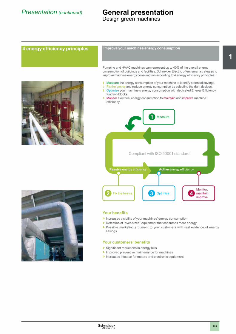
4 energy efficiency principles Improve your machines energy consumption
Pumping and HVAC machines can represent up to 40% of the overall energy consumption of buildings and facilities. Schneider Electric offers smart strategies to improve machine energy consumption according to 4 energy efficiency principles:
1 Measure the energy consumption of your machine to identify potential savings. 2 Fix the basics and reduce energy consumption by selecting the right devices.3 Optimize your machine’s energy consumption with dedicated Energy Efficiency
function blocks.4 Monitor electrical energy consumption to maintain and improve machine
efficiency.
Compliant with ISO 50001 standard
Active energy efficiencyPassive energy efficiency
Measure1
Fix the basics2 Optimize3 Monitor,maintain,improve
4
Your benefits > Increased visibility of your machines’ energy consumption > Detection of “over-sized” equipment that consumes more energy > Possible marketing argument to your customers with real evidence of energy savings
Your customers’ benefits > Significant reductions in energy bills > Improved preventive maintenance for machines > Increased lifespan for motors and electronic equipment
Presentation (continued) General presentationDesign green machines

2
1
3
4
5
6
7
8
9
10
1/4
Make your machines stand out from the start
Service and support behind you every step of the way
Stage in the product life cycle: DesignWhat we can bring you at this stage...
We find the optimum solution for your needs > Based on your needs, our Solution Application Experts and Application Design Experts (SAE/ADE) work out innovative technical solutions including: > Co-engineering > Tests > Validation
We understand your challenges > Consulting
> Audits
We execute the solution with a comprehensive service agreement > Our solution design and delivery centers (Flex Centers) are committed to quality and results and provide tests, validation, and commissioning
We improve your team’s competencies > In-class and on-site training
Stage in the product life cycle: BuildWhat we can bring you at this stage...
We take care of the delivery of your solution > Availability of components through a large worldwide network of distributors > Collaboration, management, and delivery through local partners > With Schneider Electric as your turnkey solution partner, your solutions will include:
> Project management and responsibility > Engineered systems > Third-party components management > Customizations and adaptations
We provide on-site services and support > Secondment of qualified personnel to deliver on-site engineering and technical services
We improve your service team’s competencies > Service and commissioning training > Supply chain optimization
Design
Build
Presentation (continued) General presentationService & support

2
1
3
4
5
6
7
8
9
10
1/5
Contact your HVAC and Pumping experts right now at your Customer Care Center at www.schneider-electric.com
Service and support behind you every step of the way
Operate
Improve
Stage in the product life cycle: OperateWhat we can bring you at this stage...
We provide international sales and after-sales services for you and your customers > Maintenance contracts > Spare parts and repairs > Just-in-time delivery > Return of goods > Service expertise > Diagnosis and repair > Environmental measurements (EMC, fieldbus, thermography, power quality analyses, etc.)
> Customer International Support (CIS) as a single point of contact > A network of dedicated local country experts > Web-based collaborative platform for efficient communication
We improve your customers’ competencies > In-class customer training and on-site training > Customer service and commissioning training
Stage in the product life cycle: ImproveWhat we can bring you at this stage...
We improve your pumping machine ranges > Consulting
We improve your customers’ pumping machines in their production line > Audits > Training > Migration and upgrade > Services expertise:
> Consultancy > Retrofitting
Presentation (continued) General presentationService & support

Chapter 2Solutions overview
Technical data relating to products listed in this chapter is available online at www.schneider-electric.com/hvacmachineswww.schneider-electric.com/pumping
2
1
3
4
5
6
7
8
9
10
2/1
b Application solutions for HVAC
v Air/Water cooled chillers - Flexible solution (inc. TVDA). . . . . . . . . page 2/2
v Air Handling Units - Flexible solution . . . . . . . . . . . . . . . . . . . . . . . . page 2/3
v Air/Water cooled chillers - Customized solution . . . . . . . . . . . . . . . .page 2/4
v Global overview of related functions for HVAC control solutions . . page 2/5
v Related functionsCompressor management ........................................................................ page 2/6Floating High Pressure advanced control ............................................... page 2/7Fan management .................................................................................... page 2/8Plant mode control ................................................................................... page 2/9Air Handling Unit temperature control .................................................... page 2/10PID ..........................................................................................................page 2/11Drive communication control ............................................................. page 2/12Energy management ..............................................................................page 2/13
b Application solutions for pumping
v Booster multi-drive . . . . . . . . . . . . . . . . . . . . . . . . . . . . . . . . . . . . . . . page 2/14
v Booster single-drive . . . . . . . . . . . . . . . . . . . . . . . . . . . . . . . . . . . . . . page 2/15
v Global overview of related functions for pumping control solutions . . . . . . . . . . . . . . . . . . . . . . . . . . . . . . . . . page 2/16
v Related functionsBooster working mode ......................................................................page 2/17Pump Stage and De-Stage ................................................................ page 2/18Cavitation protection .......................................................................... page 2/18Friction loss ............................................................................................ page 2/19PID ..........................................................................................................page 2/19
Contents Modicon M171/M172 logic controllers for HVAC and Pumping solutions
2/1
2
1
3
4
5
6
7
8
9
10
2/2
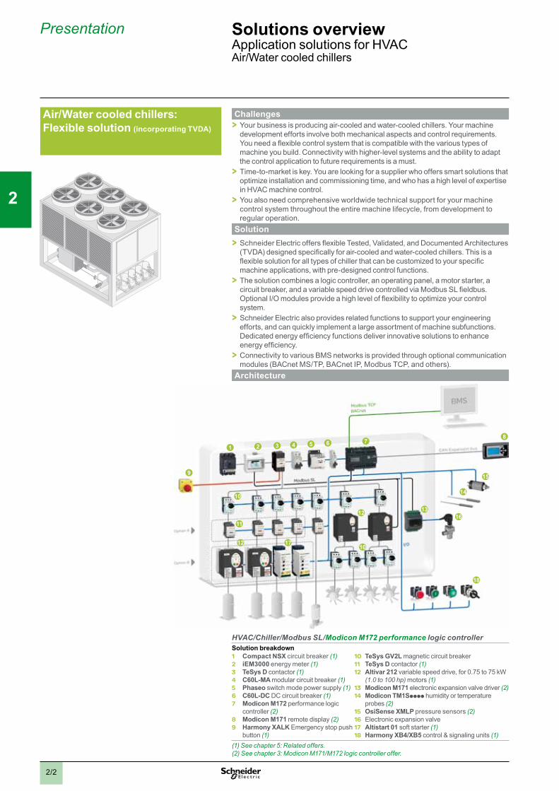
Challenges > Your business is producing air-cooled and water-cooled chillers. Your machine development efforts involve both mechanical aspects and control requirements. You need a flexible control system that is compatible with the various types of machine you build. Connectivity with higher-level systems and the ability to adapt the control application to future requirements is a must. > Time-to-market is key. You are looking for a supplier who offers smart solutions that optimize installation and commissioning time, and who has a high level of expertise in HVAC machine control. > You also need comprehensive worldwide technical support for your machine control system throughout the entire machine lifecycle, from development to regular operation.
Solution > Schneider Electric offers flexible Tested, Validated, and Documented Architectures (TVDA) designed specifically for air-cooled and water-cooled chillers. This is a flexible solution for all types of chiller that can be customized to your specific machine applications, with pre-designed control functions. > The solution combines a logic controller, an operating panel, a motor starter, a circuit breaker, and a variable speed drive controlled via Modbus SL fieldbus. Optional I/O modules provide a high level of flexibility to optimize your control system. > Schneider Electric also provides related functions to support your engineering efforts, and can quickly implement a large assortment of machine subfunctions. Dedicated energy efficiency functions deliver innovative solutions to enhance energy efficiency. > Connectivity to various BMS networks is provided through optional communication modules (BACnet MS/TP, BACnet IP, Modbus TCP, and others).
Architecture
17
3 4 5 68
9
11
12
14
15
16
1 27
10
12
13
18
10
HVAC/Chiller/Modbus SL/Modicon M172 performance logic controllerSolution breakdown1 Compact NSX circuit breaker (1)2 iEM3000 energy meter (1)3 TeSys D contactor (1)4 C60L-MA modular circuit breaker (1)5 Phaseo switch mode power supply (1)6 C60L-DC DC circuit breaker (1)7 Modicon M172 performance logic
controller (2)8 Modicon M171 remote display (2)9 Harmony XALK Emergency stop push
button (1)
10 TeSys GV2L magnetic circuit breaker11 TeSys D contactor (1)12 Altivar 212 variable speed drive, for 0.75 to 75 kW
(1.0 to 100 hp) motors (1)13 Modicon M171 electronic expansion valve driver (2)14 Modicon TM1Spppp humidity or temperature
probes (2)15 OsiSense XMLP pressure sensors (2)16 Electronic expansion valve17 Altistart 01 soft starter (1)18 Harmony XB4/XB5 control & signaling units (1)
(1) See chapter 5: Related offers.(2) See chapter 3: Modicon M171/M172 logic controller offer.
Air/Water cooled chillers: Flexible solution (incorporating TVDA)
Presentation Solutions overviewApplication solutions for HVACAir/Water cooled chillers

2
1
3
4
5
6
7
8
9
10
2/3
Challenges > Your business is producing Air Handling Units (AHUs). Your machine development efforts involve both mechanical aspects and control requirements. You need a flexible control system that is compatible with the various types of machine you build. Connectivity with higher-level systems, the ability to integrate mobile machine access, and the adaptability of the control application to future requirements is a must. > Time-to-market is key. You are looking for a supplier who offers smart solutions that optimize installation and commissioning time, and who has a high level of expertise in HVAC machine control. > You also need comprehensive worldwide technical support for your machine control system throughout the entire machine lifecycle, from development to regular operation.
Solution > Schneider Electric offers a flexible, fully-tested, complete control system designed specifically for Air Handling Units. This is an optimized solution for AHUs that can be customized to your specific machine applications, with pre-designed control functions. > The solution combines a controller, an operating panel, a motor starter, a circuit breaker, and a variable speed drive controlled via Modbus SL field bus. Optional I/O modules provide a high level of flexibility for optimizing your control system. > Schneider Electric also provides related functions to support your engineering efforts and quickly implement a large assortment of machine subfunctions. Dedicated energy efficiency functions deliver innovative solutions to enhance energy efficiency. > Connectivity to various BMS networks is provided through native Modbus SL connectivity and optional communication modules (BACnet MS/TP, BACnet/IP , Modbus TCP, and others).
Architecture
3 4 5 6 8
9
11
14
1 27
10
12
13
HVAC/AHU /Modbus SL/Modicon M172 performance logic controllerSolution breakdown
1 Compact NSX circuit breaker (1)2 iEM3000 energy meter (1)3 TeSys D contactor (1)4 C60L-MA modular circuit breaker (1)5 Phaseo switch mode power supply (1)6 C60L-DC DC circuit breaker (1)7 Modicon M172 performance logic controller (2)8 Modicon M171 remote display (2)9 Harmony XALK Emergency stop push button (1)
10 TeSys GV2L magnetic circuit breaker11 Altivar 212 variable speed drive, for
0.75 to 75 kW (1.0 to 100 hp) motors (1)12 TeSys D contactor (1)13 Harmony XB4/XB5 control & signaling
units (1)14 Differential pressure switch (1)
(1) See chapter 5: Related offers.(2) See chapter 3: Modicon M171/M172 logic controller offer.
Air Handling Units: Flexible solution
Presentation Solutions overviewApplication solutions for HVACAir Handling Units
2
1
3
4
5
6
7
8
9
10
2/4
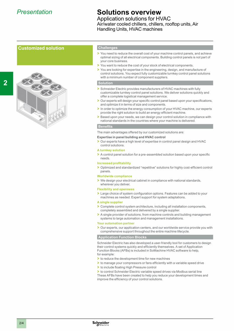
Challenges > You need to reduce the overall cost of your machine control panels, and achieve optimal sizing of all electrical components. Building control panels is not part of your core business. > You want to reduce the cost of your stock of electrical components. > You are looking for expertise in the engineering, design, and manufacture of control solutions. You expect fully customizable turnkey control panel solutions with a minimum number of component suppliers.
Solution > Schneider Electric provides manufacturers of HVAC machines with fully customizable turnkey control panel solutions. We deliver solutions quickly and offer a complete logistical management service. > Our experts will design your specific control panel based upon your specifications, and optimize it in terms of size and components. > In order to optimize the energy consumption of your HVAC machine, our experts provide the right solution to build an energy efficient machine. > Based upon your needs, we can design your control solution in compliance with national standards in the countries where your machine is delivered.
BenefitsThe main advantages offered by our customized solutions are:Expertise in panel building and HVAC control > Our experts have a high level of expertise in control panel design and HVAC control solutions.
A turnkey solution > A control panel solution for a pre-assembled solution based upon your specific needs.
Increased profitability > Optimized and standardized “repetitive” solutions for highly cost-efficient control panels.
Worldwide compliance > We design your electrical cabinet in compliance with national standards, wherever you deliver.
Flexibility and openness > Large choice of system configuration options. Features can be added to your machines as needed. Expert support for system adaptations.
A single supplier > Complete control system architecture, including all installation components, completely assembled and delivered by a single supplier. > A single provider of solutions, from machine controls and building management systems to large automation and management installations.
Your automation partner > Our experts, our application centers, and our worldwide service provide you with comprehensive support throughout the entire machine lifecycle.
Application Function BlocksSchneider Electric has also developed a user-friendly tool for customers to design their control systems quickly and efficiently themselves. A set of Application Function Blocks (AFBs) is included in SoMachine HVAC software to help, for example: > to reduce the development time for new machines > to manage your compressors or fans efficiently with a variable speed drive > to include floating High Pressure control > to control Schneider Electric variable speed drives via Modbus serial line
These AFBs have been created to help you reduce your development times and improve the efficiency of your control solutions.
Customized solution
Presentation Solutions overviewApplication solutions for HVACAir/water cooled chillers, chillers, rooftop units, Air Handling Units, HVAC machines

2
1
3
4
5
6
7
8
9
10
2/5
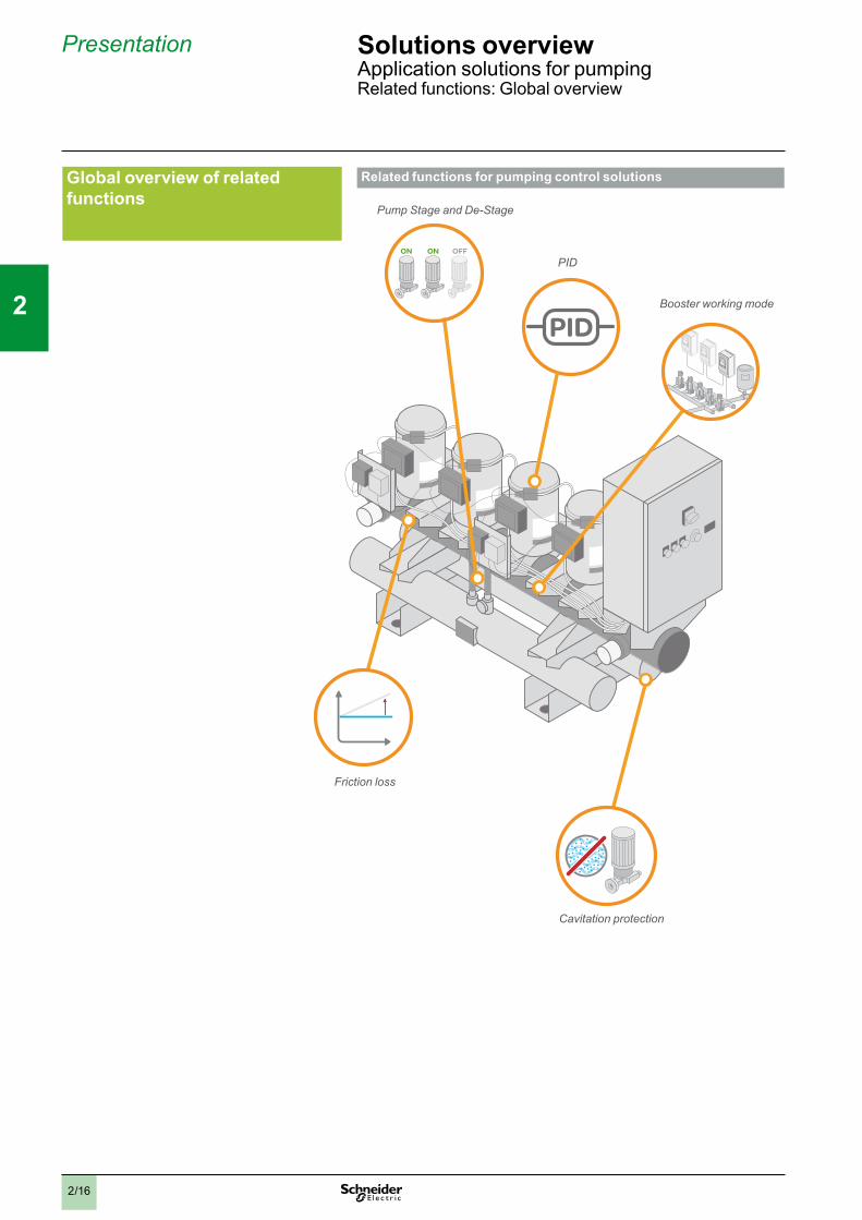
Global overview of related functions
Related functions for HVAC control solutions involving chillers
HP
+ -
Fan management
Floating High Pressure control
Compressor management
Drive communication control
Energy management
PID with autotuning
Related functions for HVAC control solutions involving Air Handling Units
Plant mode control
Air Handling Unittemperature
control
Drive communication control
Energy management
PID with autotuning
Presentation Solutions overviewApplication solutions for HVACRelated functions: Global overview

2
1
3
4
5
6
7
8
9
10
2/6
Compressor management DescriptionThe compressor management function controls a combination of fixed and variable speed compressors to maintain a constant pressure or water temperature in a chiller system.
BenefitsPerformance > Maintains the required temperature or pressure by controlling:
> the capacity of the compressors in a system with a variable speed drive > or the number of compressors
Response > Makes the system energy efficient by controlling compressor capacity prior to switching compressors on/off > Facilitates smooth operation by monitoring compressor availability and changing over to the next available compressor if an error is detected
Operating principleThe main objective of this function block is to perform control and switching of multiple compressors to maintain a pre-defined temperature or pressure in a chiller system. The temperature and pressure are measured through sensors while the setpoints are entered through the HMI. The function uses intelligent algorithms to manage switching by assigning priorities to the compressors based on availability and energy optimization.
CharacteristicsMain characteristics: > Controls scroll, screw, or reciprocating compressors > Balances operating hours based on first in first out (FIFO), last in first out (LIFO), or runtime algorithms > Supports minimum on timer, minimum off timer, and minimum cycle timer to help prevent frequent compressor switching > Supports timers to help prevent frequent compressor switching > Oil recovery function helps prevent compressor damage during partial load conditions > Helps eliminate resonance frequencies during compressor operation, thereby helping to increase compressor lifetime and reduce noise > Supports up to 8 compressors per refrigerant circuit > Allows variable speed drive regulation > Supports heating or cooling mode
Typical applications > Air and water cooled chillers > Heat pumps > Rooftop units > Compressor racks
Presentation Solutions overviewApplication solutions for HVACRelated functions: Compressor management
2
1
3
4
5
6
7
8
9
10
2/7
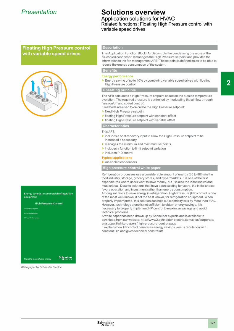
Floating High Pressure control with variable speed drives
+ -HP
DescriptionThis Application Function Block (AFB) controls the condensing pressure of the air-cooled condenser. It manages the High Pressure setpoint and provides the information to the fan management AFB. The setpoint is defined so as to be able to reduce the energy consumption of the system.
BenefitsEnergy performance > Energy saving of up to 40% by combining variable speed drives with floating High Pressure control
Operating principleThe AFB calculates a High Pressure setpoint based on the outside temperature evolution. The required pressure is controlled by modulating the air flow through fans (on/off and speed control).3 methods are used to calculate the High Pressure setpoint: > fixed High Pressure setpoint > floating High Pressure setpoint with constant offset > floating High Pressure setpoint with variable offset
CharacteristicsThis AFB: > includes a heat recovery input to allow the High Pressure setpoint to be increased if necessary > manages the minimum and maximum setpoints > includes a function to limit setpoint variation > includes PID control
Typical applications > Air-cooled condensers
High pressure control white paper
Refrigeration processes use a considerable amount of energy (30 to 80%) in the food industry, storage, grocery stores, and hypermarkets. It is one of the first expenditures where users want to save money, but it is also the least known and most critical. Despite solutions that have been existing for years, the initial choice favors operation and investment rather than energy consumption.Among solutions to save energy in refrigeration, High Pressure (HP) control is one of the most well-known, if not the best known, for refrigeration equipment. When properly implemented, this solution can help cut electricity bills by more than 30%.However, technology alone is not sufficient to obtain energy savings. It is necessary to properly implement HP control to maximize savings and avoid technical problems.A white paper has been drawn up by Schneider experts and is available to download from our website: http://www2.schneider-electric.com/sites/corporate/en/support/white-papers/high-pressure-control.pageIt explains how HP control generates energy savings versus regulation with constant HP, and gives technical constraints.
Presentation Solutions overviewApplication solutions for HVACRelated functions: Floating High Pressure control with variable speed drives
White paper by Schneider Electric

2
1
3
4
5
6
7
8
9
10
2/8
Presentation Solutions overviewApplication solutions for HVACRelated functions: Fan management
Fan management DescriptionIn order to control the condensing pressure of air-cooled condensers, this function block controls the frequency, starting, and stopping of the fans in a predetermined order to optimize their energy consumption, operating time, and availability.
BenefitsReliability > Fans with detected errors are automatically replaced in the sequence by operational fans. > Fan service life is optimized through operation sequences (FIFO, balancing hours, LIFO).
Performance > Fan switch-on and operating frequency are optimized in order to reduce the energy consumption of the air-cooled condenser.
Operating principleDepending on the input, this AFB manages the number of stages of fans to be used. Up to 12 fans per stage can be used, with a maximum of 4 stages.Regulation allows the maximum surface of the condenser to be used in order to reduce the consumption of the fans.
CharacteristicsThis AFB provides: > Linear action between PID and flow > Management of detected errors and subsequent compensation of fan operation > Operation with no delay and management of frequencies: this function increases control stability and reduces the number of fan starts/stops.
Typical applications > Air-cooled condensers
2
1
3
4
5
6
7
8
9
10
2/9
Plant mode control
OUTDOOR ROOMFREEZE FAN FIRE SCHEDULE PRESENCE
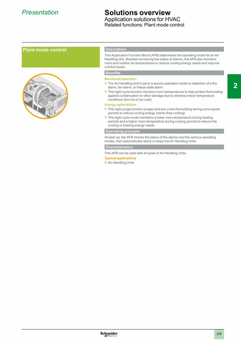
DescriptionThis Application Function Block (AFB) determines the operating mode for an Air Handling Unit. Besides monitoring the status of alarms, the AFB also monitors room and outdoor air temperatures to reduce cooling energy needs and improve comfort levels.
BenefitsMonitored operation > The Air Handling Unit is set to a secure operation mode on detection of a fire alarm, fan alarm, or freeze state alarm > The night cycle function monitors room temperatures to help protect the building against condensation or other damage due to extreme indoor temperature conditions (too hot or too cold).
Energy optimization > The night purge function purges and pre-cools the building during unoccupied periods to reduce cooling energy needs (free cooling). > The night cycle mode maintains a lower room temperature during heating periods and a higher room temperature during cooling periods to reduce the cooling or heating energy needs.
Operating principleAt start-up, the AFB checks the status of the alarms and the various operating modes, then automatically starts or stops the Air Handling Units.
CharacteristicsThis AFB can be used with all types of Air Handling Units.Typical applications > Air Handling Units
Presentation Solutions overviewApplication solutions for HVACRelated functions: Plant mode control
2
1
3
4
5
6
7
8
9
10
2/10
Air Handling Unit temperature control
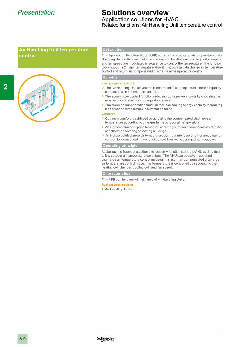
DescriptionThis Application Function Block (AFB) controls the discharge air temperature of Air Handling Units with or without mixing dampers. Heating coil, cooling coil, dampers, and fan speed are modulated in sequence to control the temperature. The function block supports 2 major temperature algorithms: constant discharge air temperature control and return air compensated discharge air temperature control.
BenefitsEnergy performance > The Air Handling Unit air volume is controlled to keep optimum indoor air quality conditions with minimum air volume. > The economizer control function reduces cooling energy costs by choosing the most economical air for cooling indoor space. > The summer compensation function reduces cooling energy costs by increasing indoor space temperature in summer seasons.
Comfort > Optimum comfort is achieved by adjusting the compensated discharge air temperature according to changes in the outdoor air temperature. > An increased indoor space temperature during summer seasons avoids climate shocks when entering or leaving buildings. > An increased discharge air temperature during winter seasons increases human comfort by compensating conductive cold from walls during winter seasons.
Operating principleAt startup, the freeze protection and recovery function stops the AHU cycling due to low outdoor air temperature conditions. The AHU can operate in constant discharge air temperature control mode or in a return air compensated discharge air temperature control mode. The temperature is controlled by sequencing the heating coil, damper, cooling coil, and fan speed.
CharacteristicsThis AFB can be used with all types of Air Handling Units.Typical applications > Air Handling Units
Presentation Solutions overviewApplication solutions for HVACRelated functions: Air Handling Unit temperature control
2
1
3
4
5
6
7
8
9
10
2/11
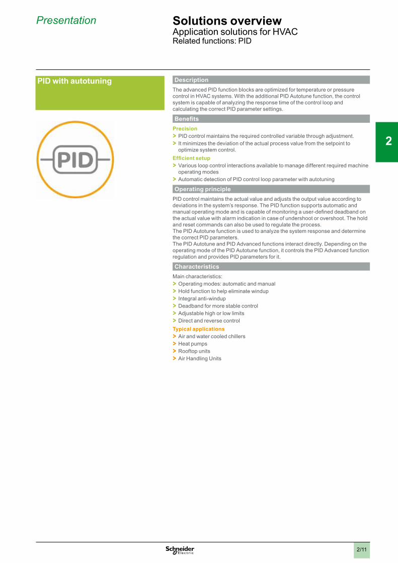
PID with autotuning DescriptionThe advanced PID function blocks are optimized for temperature or pressure control in HVAC systems. With the additional PID Autotune function, the control system is capable of analyzing the response time of the control loop and calculating the correct PID parameter settings.
BenefitsPrecision > PID control maintains the required controlled variable through adjustment. > It minimizes the deviation of the actual process value from the setpoint to optimize system control.
Efficient setup > Various loop control interactions available to manage different required machine operating modes > Automatic detection of PID control loop parameter with autotuning
Operating principlePID control maintains the actual value and adjusts the output value according to deviations in the system’s response. The PID function supports automatic and manual operating mode and is capable of monitoring a user-defined deadband on the actual value with alarm indication in case of undershoot or overshoot. The hold and reset commands can also be used to regulate the process.The PID Autotune function is used to analyze the system response and determine the correct PID parameters.The PID Autotune and PID Advanced functions interact directly. Depending on the operating mode of the PID Autotune function, it controls the PID Advanced function regulation and provides PID parameters for it.
CharacteristicsMain characteristics: > Operating modes: automatic and manual > Hold function to help eliminate windup > Integral anti-windup > Deadband for more stable control > Adjustable high or low limits > Direct and reverse control
Typical applications > Air and water cooled chillers > Heat pumps > Rooftop units > Air Handling Units
Presentation Solutions overviewApplication solutions for HVACRelated functions: PID

2
1
3
4
5
6
7
8
9
10
2/12
Drive communication control DescriptionThese function blocks provide an easy and efficient way to integrate one or several Altivar variable speed drive(s) connected, via Modbus SL fieldbus, in the Modicon M171/M172 system. The function blocks manage communication with the drives and provide control and monitoring capabilities.
BenefitsEasy integration > Easy and efficient integration of Altivar variable speed drives in the Modicon M171/M172 logic controller offer.
Complete drive control > Control and monitoring of Altivar variable speed drives on a Modicon M171/M172 logic controller without any additional development.
Operating principleThe drive communication function blocks are designed to control and monitor Altivar variable speed drives connected to a Modicon M171/M172 logic controller via Modbus SL. The function blocks completely manage the Modbus SL communication with the drive and provide direct control of the speed and drive modes. Communication and drive status are monitored permanently and detected faults are indicated on the function block.
CharacteristicsThese function blocks are designed for the Modicon M171/M172 logic controllers. They can be used with all types of HVAC machine and pumping application requiring an Altivar variable speed drive to operate e.g. compressors, fans, and pumps. Function blocks are available for Altivar 12, Altivar 21, Altivar 212, Altivar 31, Altivar 312, Altivar 32, Altivar 61, and Altivar 71 variable speed drives.Typical applications > HVAC machines > Pumping applications
Chiller OR Air Handling Unit
Altivar 212 variable speed drive
Modicon M171 logic controller
Presentation Solutions overviewApplication solutions for HVACRelated functions: Drive communication control
2
1
3
4
5
6
7
8
9
10
2/13
Energy management DescriptionThe energy management function blocks are designed for applications where the machine energy consumption needs to be metered and energy efficiency information is required. The function blocks provide an easy integration of metering devices into the system and offer calculations methods to determine the machine efficiency, COP, or ESEER (1).
BenefitsQuick and easy integration > Preprogrammed and fully tested metering functions are provided for a quick and easy integration of energy metering devices and machine efficiency calculation methods. > The function blocks provide an efficient integration of electrical metering devices either connected via Modbus SL or hardwired by using pulses. > A thermal energy calculation function block is embedded to determine the produced thermal energy. With dedicated trending and COP (1) calculation functions, machine efficiency can be monitored and analyzed in detail. > The function block allows the cooling capacity to be calculated without adding a flow meter.
Operating principleA wide range of functions are covered by a comprehensive set of metering function blocks, from retrieving energy information to energy efficiency calculations and trending.
CharacteristicsThe following function blocks are designed to be used in the Modicon M171/M172 logic controller application: > Digital input pulse totalizer: counts the digital input pulses from an energy meter > Converter of totalized pulses from energy meter: converts the digital input pulses into the consumption > Thermal power calculation: calculates the thermal power, an energy based on the flow (for water chillers) > Coefficient of performance calculation: calculates the COP based on the consumption and the thermal power > Energy meter data trend: Trend of consumption data over time
To calculate the thermal energy, a flow meter must be installed in the system and the heat capacity of the medium must be known.Thanks to a new AFB named “COPMonitor”, which combines 6 other AFBs, the COP can be calculated without the need for a flow meter. The flow is calculated based on the compressor characteristics and the thermal power produced by the machine is calculated based on the enthalpies of the machine.Typical applications > Air and water cooled chillers > Heat pumps > Rooftop units > Compressor racks
(1) COP = Coefficient Of Performance. Efficiency of the chiller or heat pump calculated by thecooling or heating power divided by electrical power consumption.ESEER = European Seasonal Energy Efficiency Ratio: seasonal efficiency of refrigeration equipment, chillers, and air conditioners calculated by the cooling or heating power divided by the electrical power consumption at different loads.
Presentation Solutions overviewApplication solutions for HVACRelated functions: Energy management
2
1
3
4
5
6
7
8
9
10
2/14
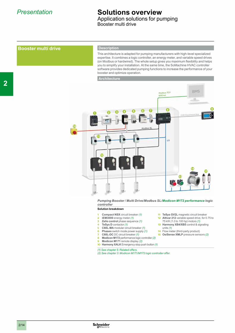
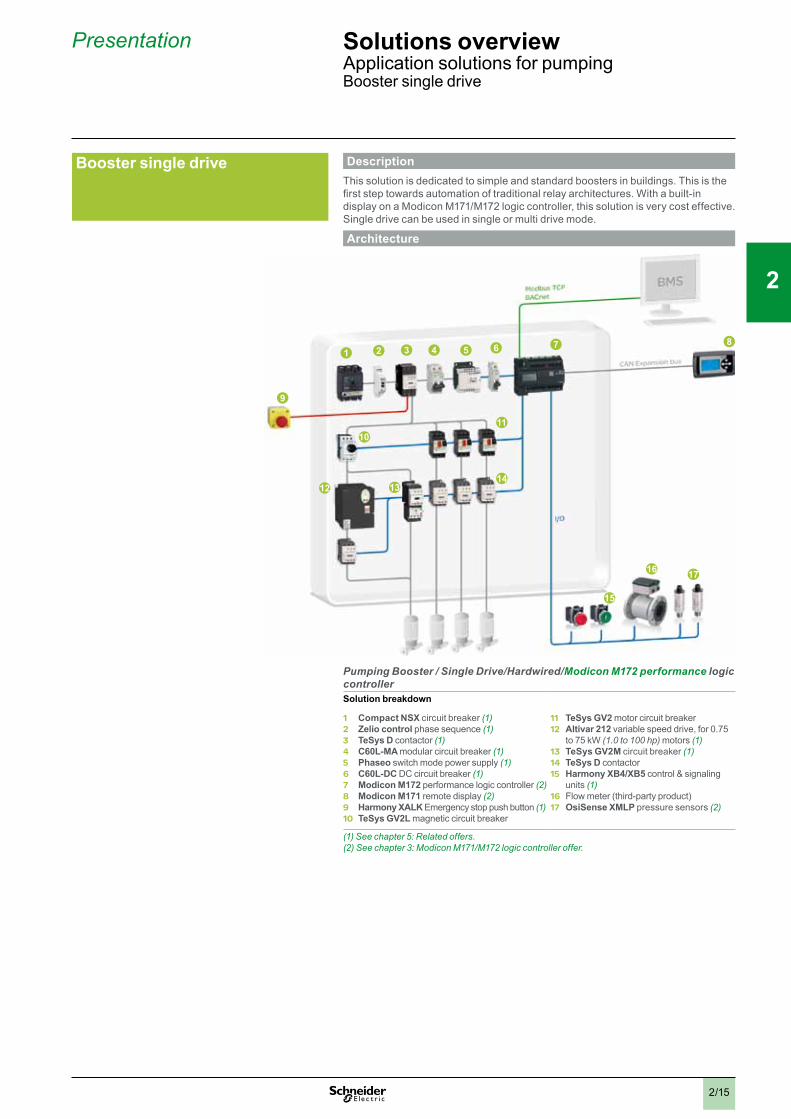
DescriptionThis architecture is adapted for pumping manufacturers with high-level specialized expertise. It combines a logic controller, an energy meter, and variable speed drives (on Modbus or hardwired). The whole setup gives you maximum flexibility and helps you to simplify your installation. At the same time, the SoMachine HVAC controller software provides dedicated pumping functions to increase the performance of your booster and optimize operation.
Architecture
3 4 5 6 8 91 2 7
11
12
10
13
1415
Pumping Booster / Multi Drive/Modbus SL/Modicon M172 performance logic controllerSolution breakdown
1 Compact NSX circuit breaker (1)2 iEM3000 energy meter (1)3 Zelio control phase sequence (1)4 TeSys D contactor (1)5 C60L-MA modular circuit breaker (1)6 Phaseo switch mode power supply (1)7 C60L-DC DC circuit breaker (1)8 Modicon M172 performance logic controller (2)9 Modicon M171 remote display (2)10 Harmony XALK Emergency stop push button (1)
11 TeSys GV2L magnetic circuit breaker12 Altivar 212 variable speed drive, for 0.75 to
75 kW (1.0 to 100 hp) motors (1)13 Harmony XB4/XB5 control & signaling
units (1) 14 Flow meter (third-party product)15 OsiSense XMLP pressure sensors (2)
(1) See chapter 5: Related offers.(2) See chapter 3: Modicon M171/M172 logic controller offer.
Booster multi drive
Presentation Solutions overviewApplication solutions for pumpingBooster multi drive
2
1
3
4
5
6
7
8
9
10
2/15
DescriptionThis solution is dedicated to simple and standard boosters in buildings. This is the first step towards automation of traditional relay architectures. With a built-in display on a Modicon M171/M172 logic controller, this solution is very cost effective. Single drive can be used in single or multi drive mode.
Architecture
3 4 5 6 81 2 7
1011
9
12 1314
15
16 17
Pumping Booster / Single Drive/Hardwired/Modicon M172 performance logic controllerSolution breakdown
1 Compact NSX circuit breaker (1)2 Zelio control phase sequence (1)3 TeSys D contactor (1)4 C60L-MA modular circuit breaker (1)5 Phaseo switch mode power supply (1)6 C60L-DC DC circuit breaker (1)7 Modicon M172 performance logic controller (2)8 Modicon M171 remote display (2)9 Harmony XALK Emergency stop push button (1)10 TeSys GV2L magnetic circuit breaker
11 TeSys GV2 motor circuit breaker12 Altivar 212 variable speed drive, for 0.75
to 75 kW (1.0 to 100 hp) motors (1)13 TeSys GV2M circuit breaker (1)14 TeSys D contactor 15 Harmony XB4/XB5 control & signaling
units (1) 16 Flow meter (third-party product)17 OsiSense XMLP pressure sensors (2)
(1) See chapter 5: Related offers.(2) See chapter 3: Modicon M171/M172 logic controller offer.
Booster single drive
Presentation Solutions overviewApplication solutions for pumpingBooster single drive
2
1
3
4
5
6
7
8
9
10
2/16
Global overview of related functions
Related functions for pumping control solutions
ON ON OFF
Friction loss
Cavitation protection
Pump Stage and De-Stage
Booster working mode
PID
Presentation Solutions overviewApplication solutions for pumpingRelated functions: Global overview

2
1
3
4
5
6
7
8
9
10
2/17
Booster working mode DescriptionThis function is used to run in the “single drive” or “multi drive” operating mode in a booster system.Definition and benefits
Multi drive > Definition: in this mode, each pump in the system is connected to an individual drive. > Main advantage: this type of arrangement provides the most energy efficient systems and a higher level of pump protection. Systems are easy to maintain.
Single drive, multi-lead > Definition: In this mode, a single drive is used to start the first pump in the system. Pump selection is based on pump operating hours or detected error status, or a user-defined priority. > Main advantage: these types of arrangement are cost effective.
Single drive, single-lead > Definition: In this mode, a single drive is used to start one pump only in the system and there is no switching of drives to another pump. > Main advantage: these types of arrangement are cost effective.
Operating principleThe main purpose of this function is to enable the user to select the optimum operating mode for the booster system. By selecting multi-lead systems, multiple pumps, connected to drives or contactors, can be controlled to switch different pumps to operate them in the most optimized manner. Switching is based upon pressure, operating hours, and the available pumps in the system.Single drive systems can select the pump to be connected and started with the only drive present in the system. The other fixed-speed pumps are started or stopped based upon pressure requirements. If an error is detected on the pump connected to the drive or it experiences a stoppage, the drive will be connected to the first available pump based upon the operating hours or detected error status of the pump, or a user-defined priority.In single drive, single-lead systems the single drive in the system is connected to only one pump and there is no switching of the drive to other pumps in the system. The other fixed-speed pumps are started by DOL based upon pressure requirements.
CharacteristicsMain characteristics: > Pump switching is performed to operate the pumps in the most optimized and energy efficient manner. > The function detects the next available pump based on operating hours, detected errors, and pressure requirements. > The function is capable of bypassing drives in the event of a detected error. > Switching values can be set from the HMI.
Typical applications > Booster pumping system consisting of multiple pumps
Presentation Solutions overviewApplication solutions for pumpingRelated functions: Booster working mode

2
1
3
4
5
6
7
8
9
10
2/18
DescriptionThe Pump Stage and De-Stage function switches a combination of fixed and variable speed pumps to maintain a constant pressure in a booster system.
BenefitsPerformance > Maintains the required pressure by performing switching between the pumps available in the system
Optimization > Makes the system energy efficient by defining the operational combination of pumps in such a way that the pumps operated by drives are given priority > Facilitates smooth operation by monitoring pump availability and changing over to the next available pump if an error is detected
Operating principleThe main objective of this function is to perform switching of multiple pumps to maintain a pre-defined pressure in the booster system. The flow and pressure are measured through sensors while the setpoints are entered from the HMI.The function uses intelligent algorithms to manage switching by assigning priorities to the pumps based on availability and energy optimization.
CharacteristicsMain characteristics: > This function is capable of maintaining the required pressure in the booster system using an energy efficient algorithm to determine optimum pump operation. > Pump switching is based on the principle of assigning higher priority to variable speed pumps and pumps with fewer operating hours. > In the event of a detected error, the function uses an intelligent algorithm to switch to the next available pump.
Typical applications > Booster pumping system consisting of multiple pumps
Pump Stage and De-Stage
ON ON OFF
Presentation Solutions overviewApplication solutions for pumpingRelated functions: Pump Stage and De-Stage
Cavitation protection DescriptionThis function stops pumps from operating under conditions of cavitation.
BenefitsOptimization > Promotes a longer service life by helping to ensure pumps do not operate in cavitation > Adapts setpoints to optimize pump operation
Monitoring > Generates alarms in case of detection of cavitation in the system
Operating principleThe main purpose of this function is to help ensure pumps do not operate under cavitation conditions. If cavitation is detected, the function immediately stops the pumps. This is achieved by reducing the pressure setpoint/flow in the system. After completing this task and resetting the alarm, the function checks the suction pressure. If the suction pressure is within the permissible limits, the function restarts the pumps in normal mode.
Characteristics > Detects abnormality in pressure using the actual suction feedback pressure value > Activates algorithms to adjust setpoints to avoid cavitation conditions > Uses a limit switch function to avoid toggling of the cavitation mode > Generates alarms on detection of cavitation conditions
Typical applications > Booster pumping system consisting of single or multiple pumps
2
1
3
4
5
6
7
8
9
10
2/19
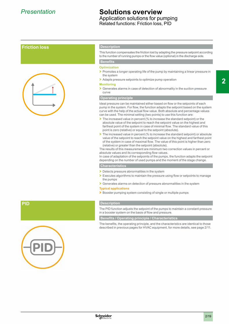
Friction loss DescriptionThis function compensates the friction lost by adapting the pressure setpoint according to the number of running pumps or the flow value (optional) in the discharge side.
BenefitsOptimization > Promotes a longer operating life of the pump by maintaining a linear pressure in the system > Adapts pressure setpoints to optimize pump operation
Monitoring > Generates alarms in case of detection of abnormality in the suction pressure curve
Operating principleIdeal pressure can be maintained either based on flow or the setpoints of each pump in the system. For flow, the function adapts the setpoint based on the system curve with the help of the actual flow value. Both absolute and percentage values can be used. The minimal setting (two points) to use this function are: > The increased value in percent (% to increase the standard setpoint) or the absolute value of the setpoint to reach the setpoint value on the highest and farthest point of the system in case of minimal flow. The standard value of this point is zero (relative) or equal to the setpoint (absolute). > The increased value in percent (% to increase the standard setpoint) or absolute value of the setpoint to reach the setpoint value on the highest and farthest point of the system in case of maximal flow. The value of this point is higher than zero (relative) or greater than the setpoint (absolute).
The results of this measurement are minimum two correction values in percent or absolute values and its corresponding flow values.In case of adaptation of the setpoints of the pumps, the function adapts the setpoint depending on the number of used pumps and the moment of the stage change.
Characteristics > Detects pressure abnormalities in the system > Executes algorithms to maintain the pressure using flow or setpoints to manage the pumps > Generates alarms on detection of pressure abnormalities in the system
Typical applications > Booster pumping system consisting of single or multiple pumps
Presentation Solutions overviewApplication solutions for pumpingRelated functions: Friction loss, PID
PID DescriptionThe PID function adjusts the setpoint of the pumps to maintain a constant pressure in a booster system on the basis of flow and pressure.
Benefits / Operating principle / CharacteristicsThe benefits, the operating principle, and the characteristics are identical to those described in previous pages for HVAC equipment, for more details, see page 2/11.
Chapter 3Hardware control platforms
b Technical data relating to products listed in this chapter is available online at www.schneider-electric.com/m171-m172

2
1
3
4
5
6
7
8
9
10
b General presentation v Maximize your business and machine performance
with MachineStruxureTM . . . . . . . . . . . . . . . . . . . . . . . . . . . . . . . . . . . . page 3/2 v Improve efficiency . . . . . . . . . . . . . . . . . . . . . . . . . . . . . . . . . . . . . . . . . page 3/3 v Increase profitability . . . . . . . . . . . . . . . . . . . . . . . . . . . . . . . . . . . . . . . page 3/4 v Reduce time-to-market . . . . . . . . . . . . . . . . . . . . . . . . . . . . . . . . . . . . . page 3/4 v Simplify integration and maintenance . . . . . . . . . . . . . . . . . . . . . . . . page 3/5
b Modicon M171/M172 logic controllers v Presentation: range, system components . . . . . . . . . . . . . . . . . . . . . page 3/6 v Modicon M171 optimized logic controllers
for simple and compact machines . . . . . . . . . . . . . . . . . . . . . . . . . . . . . . page 3/8 v Modicon M171 performance logic controllers
for complex and BMS connectable machines . . . . . . . . . . . . . . . . . . . . . page 3/8 v Modicon M172 performance logic controllers
for large and connected machines . . . . . . . . . . . . . . . . . . . . . . . . . . . . . . page 3/9 v Selection guide . . . . . . . . . . . . . . . . . . . . . . . . . . . . . . . . . . . . . . . . . . . page 3/10
b Modicon M171 optimized logic controllers > Presentation, Description ............................................................... page 3/12 > References .................................................................................... page 3/13 > Accessories ................................................................................... page 3/13
v Remote display, Wall thermostats > Presentation, Description ............................................................... page 3/14 > References .................................................................................... page 3/15 > Accessories ................................................................................... page 3/15
b Modicon M171 performance logic controllers > Presentation, Description ............................................................... page 3/16 > References .................................................................................... page 3/17 > Accessories ................................................................................... page 3/17
v Remote display > References .................................................................................... page 3/17 > Accessories ................................................................................... page 3/17
b Modicon M172 performance logic controllers > Presentation, Description ............................................................... page 3/18 > References .................................................................................... page 3/19 > Accessories ................................................................................... page 3/19
v Remote display > References .................................................................................... page 3/19 > Accessories ................................................................................... page 3/19
b I/O expansion modules v For Modicon M171 optimized logic controllers
> Presentation, Description ............................................................... page 3/20 > References .................................................................................... page 3/21
v For Modicon M171 and M172 performance logic controllers > Presentation, Description ............................................................... page 3/20 > References .................................................................................... page 3/21
v Accessories > References .................................................................................... page 3/21
b Communication modules v For M171 performance and M172 performance logic controllers
> Presentation, Description ............................................................... page 3/22 > References .................................................................................... page 3/23
b Electronic expansion valve drivers > Presentation, Description ............................................................... page 3/24 > References .................................................................................... page 3/25
v Accessories > References .................................................................................... page 3/25
b Measurement accessories v Humidity and temperature probes, NTC probes, PT1000 probes
> References .................................................................................... page 3/26 v XMLP Pressure transmitters
> Presentation ................................................................................... page 3/27 > Functions ....................................................................................... page 3/27
Contents Modicon M171/M172 logic controllers for HVAC and Pumping solutions
3/13/1

3/2
General presentation Hardware control platformModicon M171/M172 logic controllersMaximize your business and machine performance with MachineStruxure
Flexible & scalable
Customization & services
machine control
A
rchitectures & engineering
intelligence
Maximize your business and machine performance with MachineStruxure
Application Function Blocks (AFBs)
+ -HP
Fan management
Floating High Pressure control
Compressor management
Energy management
Machine builders are constantly looking for new ways to design and build more innovative machines in less time and at lower costs. MachineStruxureTM can help.The NEXT generation of MachineStruxureTM is a complete machine automation solution that provides flexible and scalable machine control, ready-to-use architectures, efficient engineering solutions, and comprehensive customization and engineering support services. It can help to meet your challenges for improved efficiency and greater productivity, as well as allow to deliver higher added value to your customers throughout the entire machine life cycle.
Ready-to-use architectures and function blocks > Tested, Validated, and Documented Architectures (TVDAs) are just one of the
ways we help to reduce design time. > Whether machines are simple or complex, Application Function Blocks (AFBs)
make system design fast and easy.
Modicon M171/M172 is part of MachineStruxure
17
3 4 5 68
9
1112
14
15
16
1 27
10
12
13
18
10
HVAC/Chiller/Modbus SL/Modicon M172 performance logic controller
Solution breakdown1 Compact NSX circuit breaker2 iEM3000 energy meter3 TeSys D contactor4 C60L-MA modular circuit breaker5 Phaseo switch mode power supply6 C60L-DC DC circuit breaker7 Modicon M172 performance logic
controller8 Modicon M171 remote display9 Harmony XALK Emergency stop push
button10 TeSys GV2L magnetic circuit breaker11 TeSys D contactor
12 Altivar 212 variable speed drive, for 0.75 to 75 kW (1.0 to 100 hp) motors
13 Modicon M171 electronic expansion valve driver
14 Modicon TM1Spppp humidity and temperature probes
15 OsiSense XMLP pressure sensors16 Electronic expansion valve 17 Altistart 01 soft starter18 Harmony XB4/XB5 control &
signaling units
2
1
3
4
5
6
7
8
9
10
2
1
3
4
5
6
7
8
9
10

3/3
Flexible and scalable performance
Whether you focus on chillers, Air Handling Units for commercial buildings, residential, or industrial applications...With the range of Modicon M171/M172 logic controllers, the next generation of MachineStruxureTM is now better positioned than ever.Multiple BMS (Building Management System) connectivity, embedded or in option, and an embedded web server enable ease in remote control; while a unique software environment supports the development of algorithms and functions that can be used on all platforms.
> Modicon™ M171 optimized logic controller for simple and compact machines is one of the smallest programmable controllers on the market. Available also for flush mounting, it requires minimal installation time and offers tremendous versatility.
> Modicon™ M171 performance logic controller for complex and BMS connectable machines can be adapted to virtually any application.
> Modicon™ M172 performance logic controller for large and connected machines with more scalability and connectivity.
Performance and connectivity
General presentation (continued)
Hardware control platformModicon M171/M172 logic controllersImprove efficiency
Improve efficiency
> Best-in-class versatility and compact size > Best-in-class performance
Scal
abili
ty
Modicon M171 optimized logic controllers
Modicon M171 performance logic controllers
Modicon M172 performance logic controllers
2
1
3
4
5
6
7
8
9
10
2
1
3
4
5
6
7
8
9
10
3/4
General presentation (continued)
Hardware control platformModicon M171/M172 logic controllersIncrease profitabilityReduce time-to-market
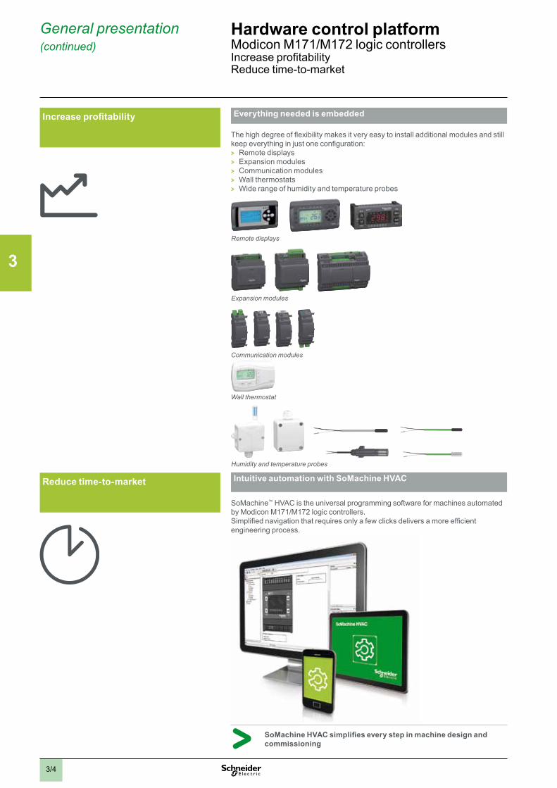
Everything needed is embedded
The high degree of flexibility makes it very easy to install additional modules and still keep everything in just one configuration:
> Remote displays > Expansion modules > Communication modules > Wall thermostats > Wide range of humidity and temperature probes
Communication modules
Remote displays
Expansion modules
Wall thermostat
Humidity and temperature probes
Intuitive automation with SoMachine HVAC
SoMachine™ HVAC is the universal programming software for machines automated by Modicon M171/M172 logic controllers.Simplified navigation that requires only a few clicks delivers a more efficient engineering process.
SoMachine HVAC simplifies every step in machine design and commissioning
Increase profitability
Reduce time-to-market
2
1
3
4
5
6
7
8
9
10
2
1
3
4
5
6
7
8
9
10
3/5
General presentation (continued)
Hardware control platformModicon M171/M172 logic controllersSimplify integration and maintenance
Connected everywhere
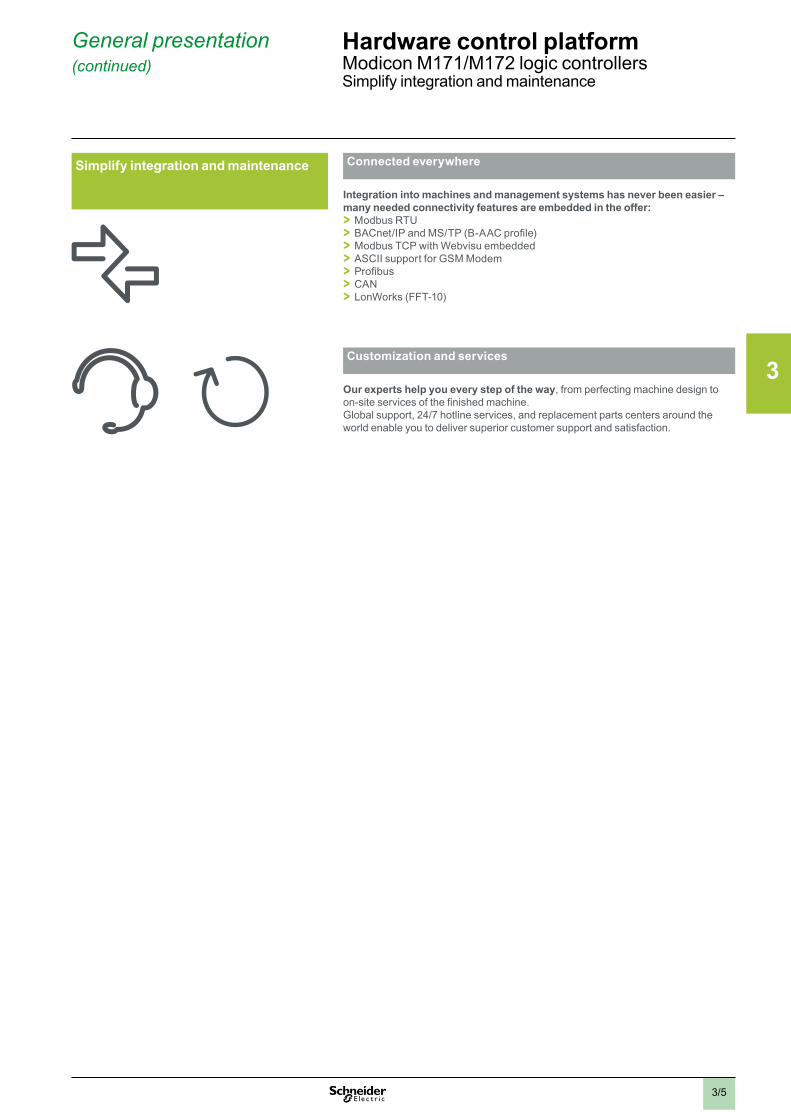
Integration into machines and management systems has never been easier – many needed connectivity features are embedded in the offer: > Modbus RTU > BACnet/IP and MS/TP (B-AAC profile) > Modbus TCP with Webvisu embedded > ASCII support for GSM Modem > Profibus > CAN > LonWorks (FFT-10)
Customization and services
Our experts help you every step of the way, from perfecting machine design to on-site services of the finished machine.Global support, 24/7 hotline services, and replacement parts centers around the world enable you to deliver superior customer support and satisfaction.
Simplify integration and maintenance
2
1
3
4
5
6
7
8
9
10
2
1
3
4
5
6
7
8
9
10

3/6
Presentation Hardware control platformModicon M171/M172 logic controllersGeneral presentation
PresentationThe Modicon M171/M172 logic controller range has been developed to manage digital and analog inputs and outputs, to offer numerous possibilities for connection to different Building Management System communication networks.
Modicon M171/M172 range
The range of Modicon M171/M172 comprises 21 logic controllers, programmable with SoMachine HVAC software, and is divided in 3 types: M171 optimized logic controllers, M171 performance logic controllers and M172 performance logic controllers.
b M171 optimized logic controllers are suitable for customized applications designed to control simple and compacts machines:
v Air/water-cooled chiller v Rooftop unit v Heat pump v Compressor rack v Ventilation unit b M171 performance logic controllers type are suitable for customized applications
designed to control complex and BMS connectable machines: v Air/water-cooled chiller v Rooftop unit v Heat pump v Precision air conditioner v Booster station v Compressor rack v Heat recovery unit b M172 performance logic controllers increase the scalability and the connectivity
achieved by M171 performance controllers. They control the same type of applications as the Modicon M171 performance do, and embed more universality and connectivity.
System components
The offer range comprises: b 21 logic controllers: v 10 M171 optimized logic controllers, v 5 M171 performance logic controllers v 6 M172 performance logic controllers
The Modicon M171/M172 logic controllers are available with or without embedded display. See pages 3/12, 3/16 and 3/18.
b 5 I/O expansion module types (mixed digital and analog): v 2 TM171EPppR for M171 and M172 performance logic controllers v 3 TM171EOppR for M171 optimized logic controllers. See page 3/20. b 5 remote displays (LED or LCD technology): v 1 TM171DGRP for for M171 and M172 performance logic controllers v 4 TM171Dpppp for M171 optimized logic controllers. See pages 3/14, 3/17 and
3/19. b 8 TM171Apppp communication modules (BMS fieldbus interfaces) to provide
to the M171 and M172 performance logic controllers a connection to: v BACnet MS/TP (B-AAC profile) or IP v Modbus SL (Serial Link) v Modbus TCP v LonWorks (FFT-10) v Profibus v CAN bus v etc, see page 3/21. b 3 TM171VEVpp electronic expansion valve drivers compatible with the entire
Modicon M171/M172 logic controller range and also with third party controllers and electronic expansion valves. See page 3/24
b 23 specific measurement accessories: TM1Spppp humidity and temperature probes. See page 3/26.
b Pressure sensors from our partner Telemecanique sensors, see page 3/27. b Adapted connection accessories: I/O connectors and cables. See pages 3/15
and 3/21. b SoMachine HVAC programming software. See page 4/2. b Programming accessories. See page 4/3.
5
1 Remote LCD display2 Communication module3 M171 performance logic controller4 I/O expansion module5 Electronic expansion valve driver
1
2 34
Measurement accessories
1 Remote LED display2 Wall thermostat3 M171 optimized logic controller4 I/O expansion module
12
3 4
1 Remote LCD display2 Communication module3 M172 performance logic controller4 I/O expansion module5 Electronic expansion valve driver
Pressure transmitters
5
1
2 34
2
1
3
4
5
6
7
8
9
10
2
1
3
4
5
6
7
8
9
10
3/7
Presentation (continued) Hardware control platformModicon M171/M172 logic controllersGeneral presentation
SoMachine HVAC programming software
General presentation (continued)Configuration software
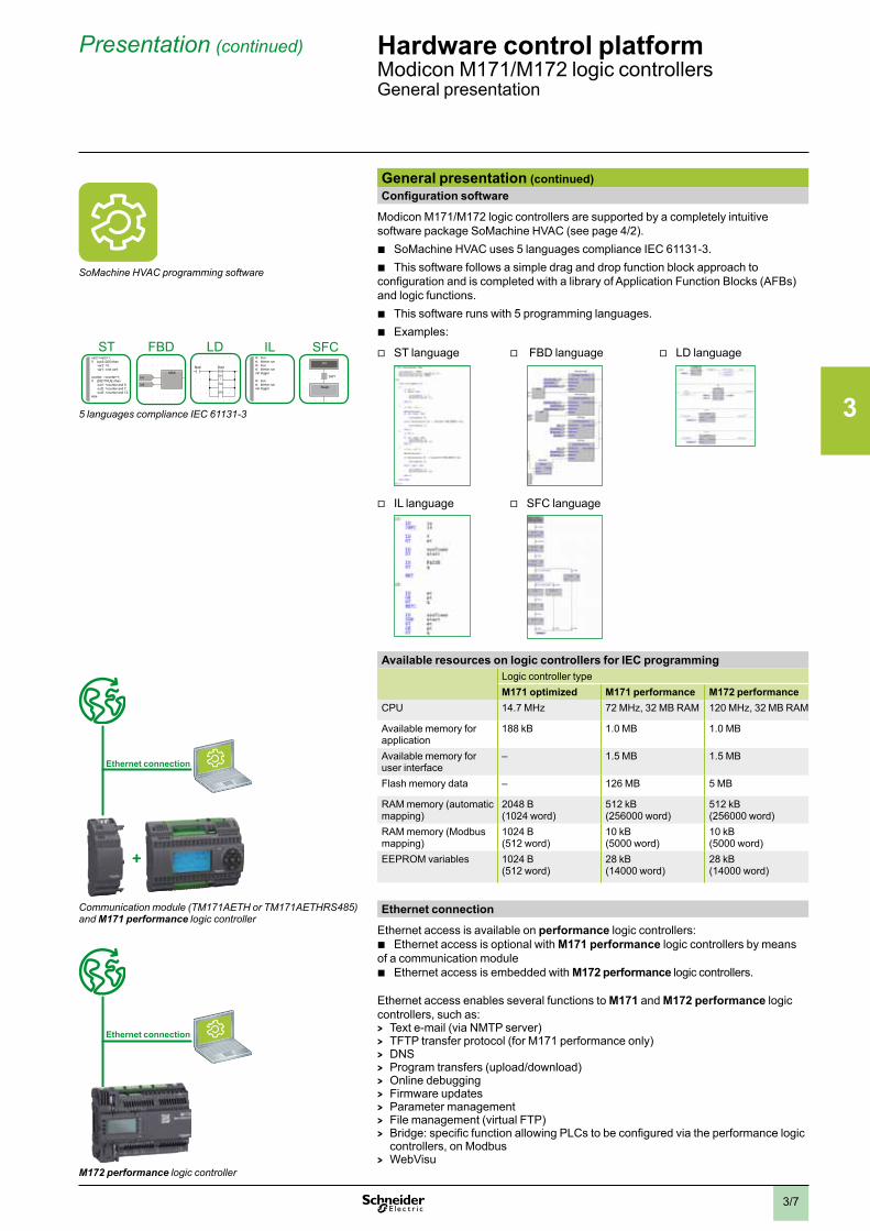
Modicon M171/M172 logic controllers are supported by a completely intuitive software package SoMachine HVAC (see page 4/2).
b SoMachine HVAC uses 5 languages compliance IEC 61131-3. b This software follows a simple drag and drop function block approach to
configuration and is completed with a library of Application Function Blocks (AFBs) and logic functions.
b This software runs with 5 programming languages. b Examples:
v ST language v FBD language v LD language
v IL language v SFC language
Available resources on logic controllers for IEC programmingLogic controller typeM171 optimized M171 performance M172 performance
CPU 14.7 MHz 72 MHz, 32 MB RAM 120 MHz, 32 MB RAM
Available memory for application
188 kB 1.0 MB 1.0 MB
Available memory for user interface
– 1.5 MB 1.5 MB
Flash memory data – 126 MB 5 MB
RAM memory (automatic mapping)
2048 B(1024 word)
512 kB(256000 word)
512 kB(256000 word)
RAM memory (Modbus mapping)
1024 B(512 word)
10 kB(5000 word)
10 kB(5000 word)
EEPROM variables 1024 B(512 word)
28 kB(14000 word)
28 kB(14000 word)
Ethernet connection
Ethernet access is available on performance logic controllers: b Ethernet access is optional with M171 performance logic controllers by means
of a communication module b Ethernet access is embedded with M172 performance logic controllers.
Ethernet access enables several functions to M171 and M172 performance logic controllers, such as: > Text e-mail (via NMTP server) > TFTP transfer protocol (for M171 performance only) > DNS > Program transfers (upload/download) > Online debugging > Firmware updates > Parameter management > File management (virtual FTP) > Bridge: specific function allowing PLCs to be configured via the performance logic
controllers, on Modbus > WebVisu
Communication module (TM171AETH or TM171AETHRS485) and M171 performance logic controller
Ethernet connection
M172 performance logic controller
Ethernet connection
. . . . . .
. . . . . . . .
. . . . . . . .
. . . . . . . .
. . . . . . . .
. . . . . . . .
. . . . . .
Init
Step0
SW1
. . . . . .
. . . . . . . .
. . . . . . . .
. . . . . . . .
. . . . . . . .
. . . . . . . .
. . . . . .
Main Start
En1
En2
En3
N
/
. . . . . .
. . . . . . . .
. . . . . . . .
. . . . . . . .
. . . . . . . .
. . . . . . . .
. . . . . .
MAXIn1
In2
ld truest blinker.runld truest blinker.runcal trigger
ld truest blinker.runcal trigger
var2:=var2+1;if (var2=200) then var2: =0; var1: =not var1;
counter: =counter+1;if (DI2=TRUE) then out1: =counter and 5; out2: =counter and 7; out3: =counter and 12;else
ST FBD IL SFCLD
5 languages compliance IEC 61131-3
2
1
3
4
5
6
7
8
9
10
2
1
3
4
5
6
7
8
9
10
3/8
Presentation (continued) Hardware control platformModicon M171/M172 logic controllersGeneral presentation
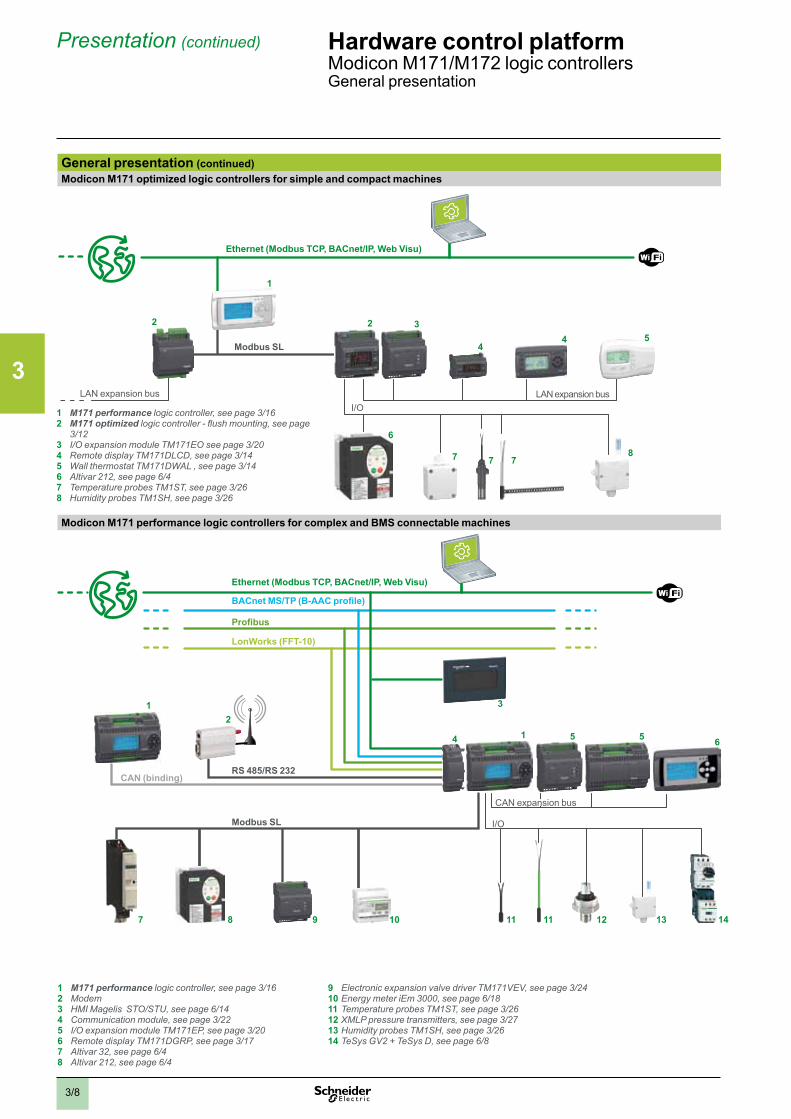
General presentation (continued)Modicon M171 optimized logic controllers for simple and compact machines
Ethernet (Modbus TCP, BACnet/IP, Web Visu)
LAN expansion bus
Modbus SL
I/O
1
3
44 5
6
7 7 78
2
LAN expansion bus
2
Modicon M171 performance logic controllers for complex and BMS connectable machines
Ethernet (Modbus TCP, BACnet/IP, Web Visu)
BACnet MS/TP (B-AAC profile)
Profibus
LonWorks (FFT-10)
RS 485/RS 232
CAN expansion bus
Modbus SL I/O
CAN (binding)
3
1 5 5 6
2
7 8 9 10 11 11 12 13 14
4
1
1 M171 performance logic controller, see page 3/162 M171 optimized logic controller - flush mounting, see page
3/123 I/O expansion module TM171EO see page 3/204 Remote display TM171DLCD, see page 3/145 Wall thermostat TM171DWAL , see page 3/146 Altivar 212, see page 6/47 Temperature probes TM1ST, see page 3/268 Humidity probes TM1SH, see page 3/26
1 M171 performance logic controller, see page 3/162 Modem3 HMI Magelis STO/STU, see page 6/144 Communication module, see page 3/225 I/O expansion module TM171EP, see page 3/206 Remote display TM171DGRP, see page 3/177 Altivar 32, see page 6/48 Altivar 212, see page 6/4
9 Electronic expansion valve driver TM171VEV, see page 3/2410 Energy meter iEm 3000, see page 6/1811 Temperature probes TM1ST, see page 3/2612 XMLP pressure transmitters, see page 3/2713 Humidity probes TM1SH, see page 3/2614 TeSys GV2 + TeSys D, see page 6/8
2
1
3
4
5
6
7
8
9
10
2
1
3
4
5
6
7
8
9
10

3/9
Presentation (continued) Hardware control platformModicon M171/M172 logic controllersGeneral presentation
General presentation (continued)M172 performance logic controllers for large and connected machines
Ethernet (Modbus TCP, BACnet/IP, Web Visu)BACnet MS/TP (B-AAC profile)
LonWorks (FFT-10)
Konnex (KNX)
RS 485/RS 232
CAN expansion bus
Modbus TCP
Modbus SL 2
I/O
CAN (binding)
5 6 62
7
8 9 10 11 1312 13 14 15
3 4
1
1
Modbus SL 1
16
1 M172 performance logic controller, see page 3/182 Modem3 spaceLYnk gateway, see page 5/54 HMI Magelis STO/STU, see page 6/45 Communication module TM171ALON, see page 3/226 I/O expansion module TM171EP, see page 3/207 Remote display TM171DGRP, see page 3/178 Altivar 32, see page 6/49 Altivar 212, see page 6/4
10 Electronic expansion valve driver TM171VEV, see page 3/2411 Energy meter iEm 3000, see page 6/1812 Room controller SE8000, see page 6/213 Temperature probes TM1ST, see page 3/2614 XMLP pressure transmitters, see page 3/2715 Humidity probes TM1SH, see page 3/2616 TeSys GV2 + TeSys D, see page 6/8
2
1
3
4
5
6
7
8
9
10
2
1
3
4
5
6
7
8
9
10
3/113/10
8.0
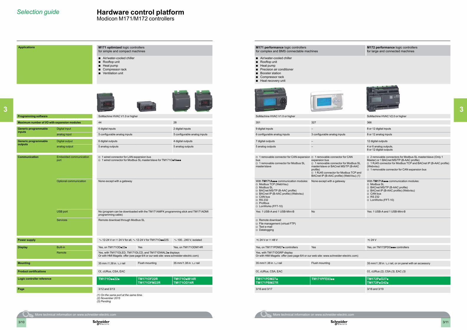
Selection guide Hardware control platformModicon M171/M172 controllers
Applications M171 optimized logic controllersfor simple and compact machines
M171 performance logic controllersfor complex and BMS connectable machines
M172 performance logic controllersfor large and connected machines
b Air/water-cooled chiller b Rooftop unit b Heat pump b Compressor rack b Ventilation unit
b Air/water-cooled chiller b Rooftop unit b Heat pump b Precision air conditioner b Booster station b Compressor rack b Heat recovery unit
Programming software SoMachine HVAC V1.0 or higher SoMachine HVAC V1.0 or higher SoMachine HVAC V2.0 or higher
Maximum number of I/O with expansion modules 44 28 351 327 366
Generic programmable inputs
Digital input 6 digital inputs 2 digital inputs 9 digital inputs – 8 or 12 digital inputs
analog input 5 configurable analog inputs 5 configurable analog inputs 6 configurable analog inputs 3 configurable analog inputs 8 or 12 analog inputs
Generic programmable outputs
Digital output 6 digital outputs 4 digital outputs 7 digital outputs – 12 digital outputs
analog output 5 analog outputs 5 analog outputs 5 analog outputs – 4 or 6 analog outputs, 8 or 12 digital outputs
Communication Embedded communication port
v 1 wired connector for LAN expansion bus v 1 wired connector for Modbus SL master/slave for TM171OpMppp
v 1 removable connector for CAN expansion bus
v 1 removable connector for Modbus SL master/slave
v 1 removable connector for CAN expansion bus
v 1 removable connector for Modbus SL master/slave or BACnet MS/TP (B-AAC profile)
v 1 RJ45 connector for Modbus TCP and BACnet IP (B-AAC profile) (WebVisu) (1)
v 2 removable connectors for Modbus SL master/slave (Only 1 Master) or 1 BACnet MS/TP (B-AAC profile)
v 1 RJ45 connector for Modbus TCP and BACnet IP (B-AAC profile) (Webvisu)
v 1 removable connector for CAN expansion bus
Optional communication None except with a gateway With TM171Appp communication modules: v Modbus TCP (WebVisu) v Modbus SL v BACnet MS/TP (B-AAC profile) v BACnet IP (B-AAC profile) (Webvisu) v CAN bus v RS 232 v Profibus v LonWorks (FFT-10)
None except with a gateway With TM171Appp communication modules: v Modbus SL v BACnet MS/TP (B-AAC profile) v BACnet IP (B-AAC profile) (Webvisu) v CAN bus v RS 232 v LonWorks (FFT-10)
USB port No (program can be downloaded with the TM171AMFK programming stick and TM171ADMI programming cable)
Yes: 1 USB-A and 1 USB-Mini-B No Yes: 1 USB-A and 1 USB-Mini-B
Services Remote download through Modbus SL v Remote download v File management (virtual FTP) v Text e-mail v Datalogging
Power supply a 12-24 V or c 24 V for all, a 12-24 V for TM171Opp22S a 100...240 V, isolated z 24 V or c 48 V z 24 V
Display Built-in Yes, on TM171ODp22p Yes Yes, on TM171ODM14R Yes, on TM171PDM27p controllers Yes Yes, on TM172PDGppp controllers
Remote Yes, with TM171DLED, TM171DLCD, and TM171DWAL2p displaysOr with HMI Magelis offer (see page 6/4 or our web site: www.schneider-electric.com)
Yes, with TM171DGRP displayOr with HMI Magelis offer (see page 6/4 or our web site: www.schneider-electric.com)
Mounting 35 mm /1.38 in. rail Flush mounting 35 mm/1.38 in. rail 35 mm/1.38 in. rail Flush mounting 35 mm/1.38 in. rail, or on panel with an accessory
Product certifications e, cURus, CSA, EAC e, cURus, CSA, EAC e, cURus (2), CSA (3), EAC (3)
Logic controller reference TM171Opp22p TM171OF22RTM171OFM22R
TM171OpM14RTM171OD14R
TM171PDM27pTM171PBM27R
TM171PFE03pp TM172PpG27pTM172PpG42p
Page 3/12 and 3/13 3/16 and 3/17 3/18 and 3/19
(1) On the same port at the same time.(2) November 2015(3) Pending
2
1
3
4
5
6
7
8
9
10
2
1
3
4
5
6
7
8
9
10
2
1
3
4
5
6
7
8
9
10
2
1
3
4
5
6
7
8
9
10
3/12
Presentation, description
Hardware control platformModicon M171/M172 logic controllersM171 optimized logic controllers
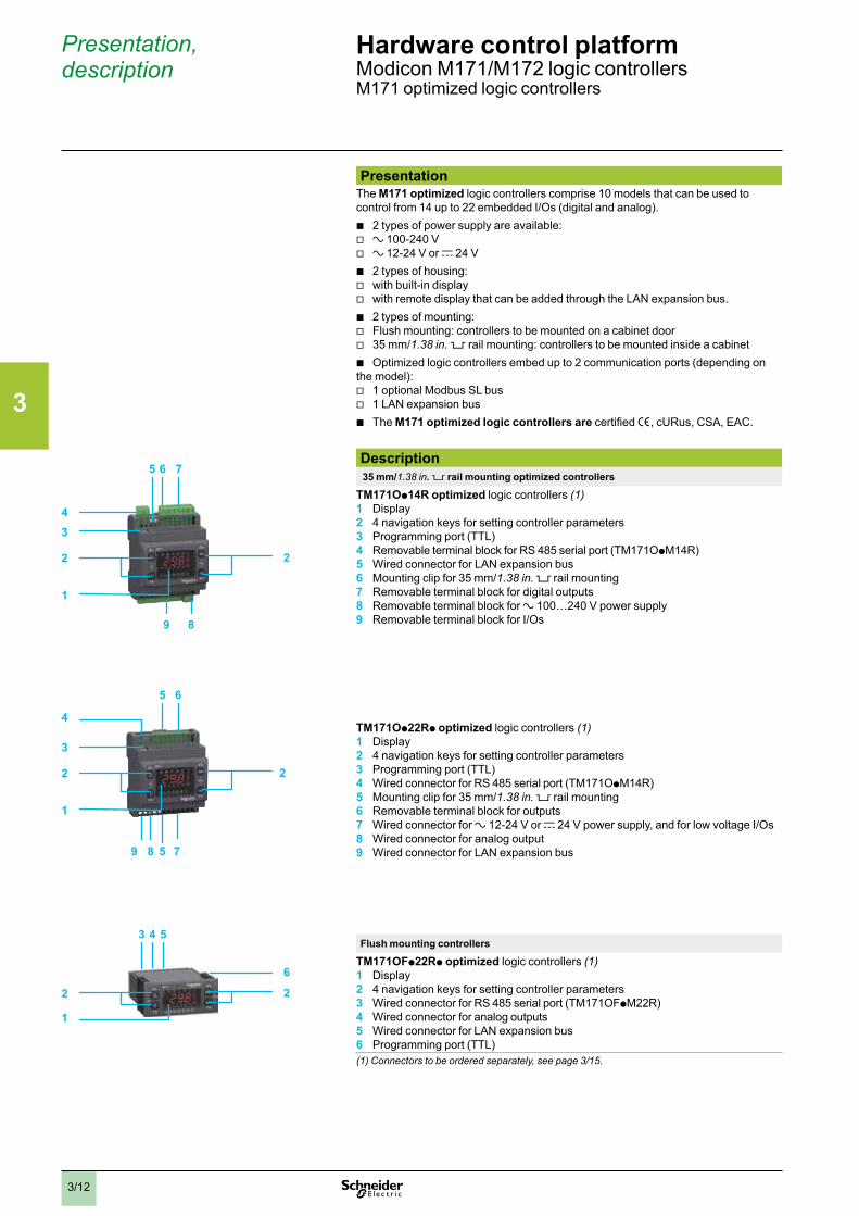
PresentationThe M171 optimized logic controllers comprise 10 models that can be used to control from 14 up to 22 embedded I/Os (digital and analog).
b 2 types of power supply are available: v a 100-240 V v a 12-24 V or c 24 V b 2 types of housing: v with built-in display v with remote display that can be added through the LAN expansion bus. b 2 types of mounting: v Flush mounting: controllers to be mounted on a cabinet door v 35 mm/1.38 in. 5 rail mounting: controllers to be mounted inside a cabinet b Optimized logic controllers embed up to 2 communication ports (depending on
the model): v 1 optional Modbus SL bus v 1 LAN expansion bus b The M171 optimized logic controllers are certified e, cURus, CSA, EAC.
Description 35 mm/1.38 in . 5 rail mounting optimized controllers
TM171Op14R optimized logic controllers (1)1 Display2 4 navigation keys for setting controller parameters3 Programming port (TTL)4 Removable terminal block for RS 485 serial port (TM171OpM14R)5 Wired connector for LAN expansion bus6 Mounting clip for 35 mm/1.38 in. rail mounting7 Removable terminal block for digital outputs8 Removable terminal block for a 100…240 V power supply9 Removable terminal block for I/Os
TM171Op22Rp optimized logic controllers (1)1 Display 2 4 navigation keys for setting controller parameters3 Programming port (TTL)4 Wired connector for RS 485 serial port (TM171OpM14R)5 Mounting clip for 35 mm/1.38 in. rail mounting6 Removable terminal block for outputs7 Wired connector for a 12-24 V or c 24 V power supply, and for low voltage I/Os8 Wired connector for analog output9 Wired connector for LAN expansion bus
Flush mounting controllers
TM171OFp22Rp optimized logic controllers (1)1 Display2 4 navigation keys for setting controller parameters3 Wired connector for RS 485 serial port (TM171OFpM22R)4 Wired connector for analog outputs5 Wired connector for LAN expansion bus6 Programming port (TTL)(1) Connectors to be ordered separately, see page 3/15.
5 6 7
89
1
2
43
2
5
5
6
7
1
2
4
3
2
89
53 4
1
2 2
6
2
1
3
4
5
6
7
8
9
10
2
1
3
4
5
6
7
8
9
10
3/13
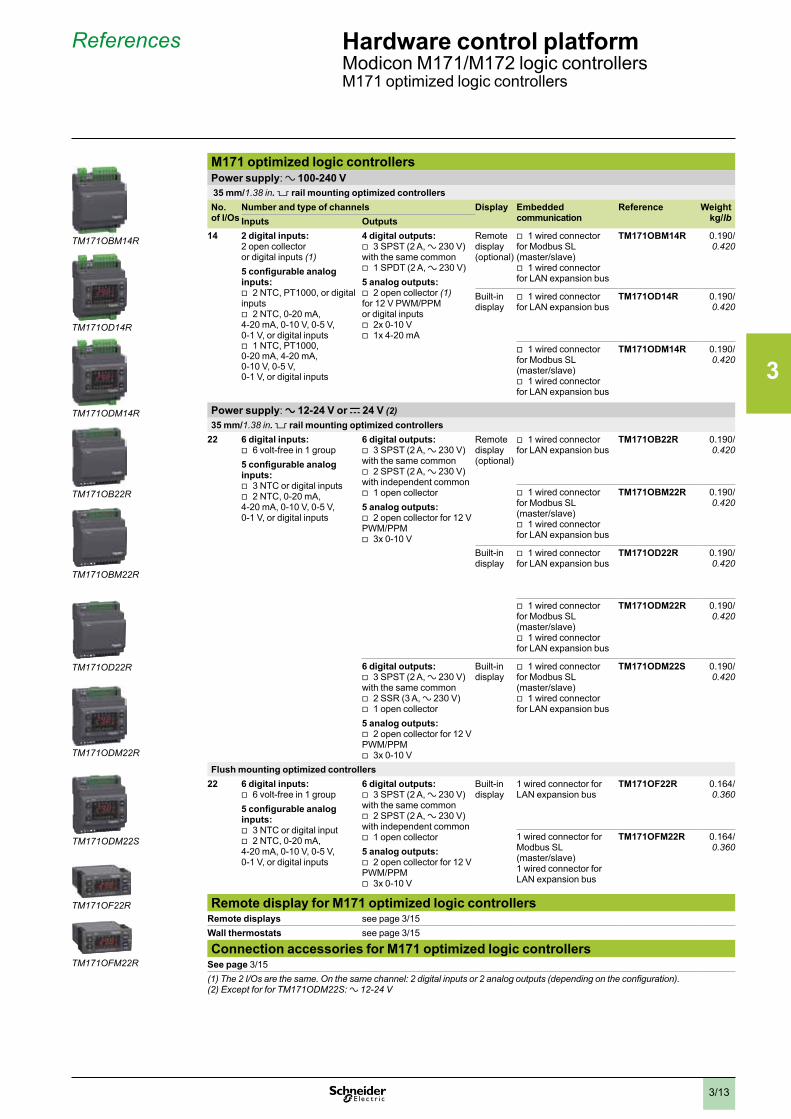
References Hardware control platformModicon M171/M172 logic controllersM171 optimized logic controllers
M171 optimized logic controllersPower supply: a 100-240 V 35 mm/1.38 in . 5 rail mounting optimized controllersNo. of I/Os
Number and type of channels Display Embedded communication
Reference Weightkg/lbInputs Outputs
14 2 digital inputs:2 open collectoror digital inputs (1)5 configurable analog inputs:
v 2 NTC, PT1000, or digital inputs
v 2 NTC, 0-20 mA, 4-20 mA, 0-10 V, 0-5 V, 0-1 V, or digital inputs
v 1 NTC, PT1000, 0-20 mA, 4-20 mA, 0-10 V, 0-5 V, 0-1 V, or digital inputs
4 digital outputs: v 3 SPST (2 A, a 230 V)
with the same common v 1 SPDT (2 A, a 230 V)
5 analog outputs: v 2 open collector (1)
for 12 V PWM/PPM or digital inputs
v 2x 0-10 V v 1x 4-20 mA
Remote display (optional)
v 1 wired connector for Modbus SL (master/slave)
v 1 wired connector for LAN expansion bus
TM171OBM14R 0.190/0.420
Built-in display
v 1 wired connector for LAN expansion bus
TM171OD14R 0.190/0.420
v 1 wired connector for Modbus SL (master/slave)
v 1 wired connector for LAN expansion bus
TM171ODM14R 0.190/0.420
Power supply: a 12-24 V or c 24 V (2)35 mm/1.38 in . 5 rail mounting optimized controllers
22 6 digital inputs: v 6 volt-free in 1 group
5 configurable analog inputs:
v 3 NTC or digital inputs v 2 NTC, 0-20 mA,
4-20 mA, 0-10 V, 0-5 V, 0-1 V, or digital inputs
6 digital outputs: v 3 SPST (2 A, a 230 V)
with the same common v 2 SPST (2 A, a 230 V)
with independent common v 1 open collector
5 analog outputs: v 2 open collector for 12 V
PWM/PPM v 3x 0-10 V
Remote display (optional)
v 1 wired connector for LAN expansion bus
TM171OB22R 0.190/0.420
v 1 wired connector for Modbus SL (master/slave)
v 1 wired connector for LAN expansion bus
TM171OBM22R 0.190/0.420
Built-in display
v 1 wired connector for LAN expansion bus
TM171OD22R 0.190/0.420
v 1 wired connector for Modbus SL (master/slave)
v 1 wired connector for LAN expansion bus
TM171ODM22R 0.190/0.420
6 digital outputs: v 3 SPST (2 A, a 230 V)
with the same common v 2 SSR (3 A, a 230 V) v 1 open collector
5 analog outputs: v 2 open collector for 12 V
PWM/PPM v 3x 0-10 V
Built-in display
v 1 wired connector for Modbus SL (master/slave)
v 1 wired connector for LAN expansion bus
TM171ODM22S 0.190/0.420
Flush mounting optimized controllers22 6 digital inputs:
v 6 volt-free in 1 group5 configurable analog inputs:
v 3 NTC or digital input v 2 NTC, 0-20 mA,
4-20 mA, 0-10 V, 0-5 V, 0-1 V, or digital inputs
6 digital outputs: v 3 SPST (2 A, a 230 V)
with the same common v 2 SPST (2 A, a 230 V)
with independent common v 1 open collector
5 analog outputs: v 2 open collector for 12 V
PWM/PPM v 3x 0-10 V
Built-in display
1 wired connector for LAN expansion bus
TM171OF22R 0.164/0.360
1 wired connector for Modbus SL (master/slave)1 wired connector for LAN expansion bus
TM171OFM22R 0.164/0.360
Remote display for M171 optimized logic controllersRemote displays see page 3/15Wall thermostats see page 3/15
Connection accessories for M171 optimized logic controllersSee page 3/15(1) The 2 I/Os are the same. On the same channel: 2 digital inputs or 2 analog outputs (depending on the configuration).(2) Except for for TM171ODM22S: a 12-24 V
TM171ODM22S
TM171OB22R
TM171OBM22R
TM171ODM14R
TM171OF22R
TM171OFM22R
TM171OBM14R
TM171OD14R
TM171ODM22R
TM171OD22R
2
1
3
4
5
6
7
8
9
10
2
1
3
4
5
6
7
8
9
10
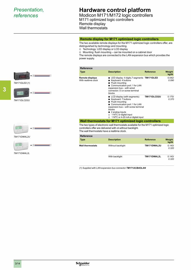
3/14
Presentation, references
Hardware control platformModicon M171/M172 logic controllersM171 optimized logic controllersRemote displayWall thermostats
Remote display for M171 optimized logic controllersThe two available remote displays for the M171 optimized logic controllers offer, are distinguished by technology and mounting.
v Technology: LED display or LCD display v Mounting: flush mounting – can be mounted on a cabinet door
The remote displays are connected to the LAN expansion bus which provides the power supply.
ReferenceType Description Reference Weight
kg/lbRemote displaysWith realtime clock
b LED display: 4 digits,7 segments b Keyboard: 4 buttons b Flush mounting b Communication port: 1 for LAN
expansion bus – with wired connector (1) or screw terminal blocks
TM171DLED 0.042/0.090
b LCD display (with segments) b Keyboard: 7 buttons b Flush mounting b Communication port: 1 for LAN
expansion bus – with screw terminal blocks
b 2 analog inputs v 1 NTC or digital input v 1 NTC or 4-20 mA or digital input
TM171DLCD2U 0.170/0.370
Wall thermostats for M171 optimized logic controllersThe two types of electronic wall thermostats available for the M171 optimized logic controllers offer are delivered with ot without backlight.The wall thermostats have a realtime clock.
ReferenceType Description Reference Weight
kg/lbWall thermostats Without backlight TM171DWAL2U 0.143/
0.320
With backlight TM171DWAL2L 0.143/0.320
(1) Supplied with LAN expansion bus connector TM171ACB4OLAN
TM171DLED (1)
TM171DLCD2U
TM171DWAL2U
TM171DWAL2L
+
+
+
+
2
1
3
4
5
6
7
8
9
10
2
1
3
4
5
6
7
8
9
10
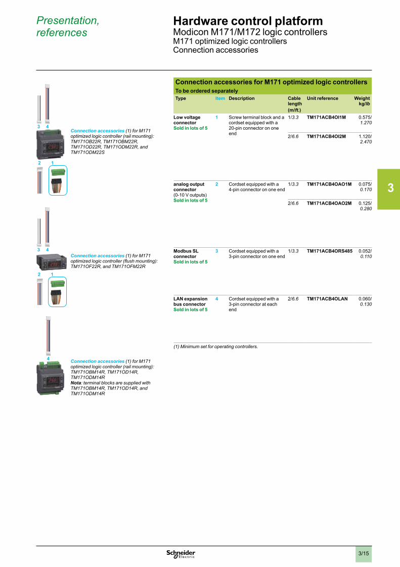
3/15
Presentation, references
Hardware control platformModicon M171/M172 logic controllersM171 optimized logic controllersConnection accessories
Connection accessories for M171 optimized logic controllersTo be ordered separatelyType Item Description Cable
length(m/ft .)
Unit reference Weightkg/lb
Low voltage connectorSold in lots of 5
1 Screw terminal block and a cordset equipped with a 20-pin connector on one end
1/3.3 TM171ACB4OI1M 0.575/1.270
2/6.6 TM171ACB4OI2M 1.120/ 2.470
analog output connector(0-10 V outputs)Sold in lots of 5
2 Cordset equipped with a 4-pin connector on one end
1/3.3 TM171ACB4OAO1M 0.075/ 0.170
2/6.6 TM171ACB4OAO2M 0.125/0.280
Modbus SL connectorSold in lots of 5
3 Cordset equipped with a 3-pin connector on one end
1/3.3 TM171ACB4ORS485 0.052/0.110
LAN expansion bus connectorSold in lots of 5
4 Cordset equipped with a 3-pin connector at each end
2/6.6 TM171ACB4OLAN 0.060/0.130
(1) Minimum set for operating controllers.
Connection accessories (1) for M171 optimized logic controller (rail mounting): TM171OB22R, TM171OBM22R, TM171OD22R, TM171ODM22R, and TM171ODM22S
3 4
2 1
Connection accessories (1) for M171 optimized logic controller (flush mounting): TM171OF22R, and TM171OFM22R
3 4
2 1
Connection accessories (1) for M171 optimized logic controller (rail mounting): TM171OBM14R, TM171OD14R, TM171ODM14RNota: terminal blocks are supplied with TM171OBM14R, TM171OD14R, and TM171ODM14R
4
2
1
3
4
5
6
7
8
9
10
2
1
3
4
5
6
7
8
9
10
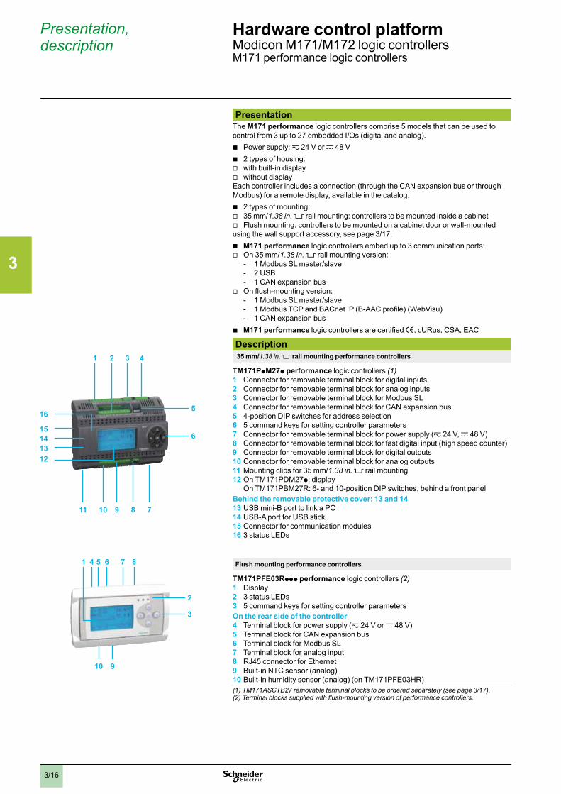
3/16
Presentation, description
Hardware control platformModicon M171/M172 logic controllersM171 performance logic controllers
PresentationThe M171 performance logic controllers comprise 5 models that can be used to control from 3 up to 27 embedded I/Os (digital and analog).
b Power supply: z 24 V or c 48 V b 2 types of housing: v with built-in display v without display
Each controller includes a connection (through the CAN expansion bus or through Modbus) for a remote display, available in the catalog.
b 2 types of mounting: v 35 mm/1.38 in. 5 rail mounting: controllers to be mounted inside a cabinet v Flush mounting: controllers to be mounted on a cabinet door or wall-mounted
using the wall support accessory, see page 3/17. b M171 performance logic controllers embed up to 3 communication ports: v On 35 mm/1.38 in. 5 rail mounting version:
- 1 Modbus SL master/slave - 2 USB - 1 CAN expansion bus
v On flush-mounting version: - 1 Modbus SL master/slave - 1 Modbus TCP and BACnet IP (B-AAC profile) (WebVisu) - 1 CAN expansion bus
b M171 performance logic controllers are certified e, cURus, CSA, EAC
Description 35 mm/1.38 in . 5 rail mounting performance controllers
TM171PpM27p performance logic controllers (1)1 Connector for removable terminal block for digital inputs2 Connector for removable terminal block for analog inputs3 Connector for removable terminal block for Modbus SL4 Connector for removable terminal block for CAN expansion bus5 4-position DIP switches for address selection6 5 command keys for setting controller parameters7 Connector for removable terminal block for power supply (z 24 V, c 48 V)8 Connector for removable terminal block for fast digital input (high speed counter)9 Connector for removable terminal block for digital outputs10 Connector for removable terminal block for analog outputs11 Mounting clips for 35 mm/1.38 in. rail mounting12 On TM171PDM27p: display
On TM171PBM27R: 6- and 10-position DIP switches, behind a front panelBehind the removable protective cover: 13 and 1413 USB mini-B port to link a PC14 USB-A port for USB stick15 Connector for communication modules16 3 status LEDs
Flush mounting performance controllers
TM171PFE03Rppp performance logic controllers (2)1 Display2 3 status LEDs3 5 command keys for setting controller parametersOn the rear side of the controller4 Terminal block for power supply (z 24 V or c 48 V)5 Terminal block for CAN expansion bus6 Terminal block for Modbus SL7 Terminal block for analog input8 RJ45 connector for Ethernet9 Built-in NTC sensor (analog)10 Built-in humidity sensor (analog) (on TM171PFE03HR)(1) TM171ASCTB27 removable terminal blocks to be ordered separately (see page 3/17).(2) Terminal blocks supplied with flush-mounting version of performance controllers.
1 2 3 4
5
2
6
3
7891011
12131415
16
1 4 5 6 7 8
910
2
1
3
4
5
6
7
8
9
10
2
1
3
4
5
6
7
8
9
10
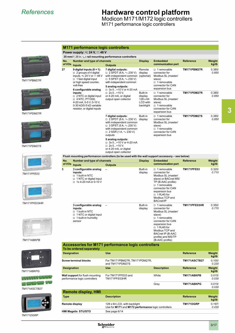
3/17
References Hardware control platformModicon M171/M172 logic controllersM171 performance logic controllers
M171 performance logic controllersPower supply: z 24 V, c 48 V 35 mm/1.38 in . 5 rail mounting performance controllersNo. of I/Os
Number and type of channels Display Embedded communication port
Reference Weightkg/lbInputs Outputs
27 9 digital inputs (8 + 1): v 2 groups of 4 digital
inputs, z 24 V or c 48 V v 1 fast digital input
or high speed counter, volt-free6 configurable analog inputs:
v 2 NTC or digital input v 4 NTC, PT1000,
4-20 mA, 0-5 V, 0-10 V, 0-30 kΩ/0-5 kΩ variable resistor, or digital inputs
7 digital outputs: v 2 SPDT (8 A, a 230 V)
with independent common v 5 SPST (5 A, a 230 V)
with independent common5 analog outputs:
v 3x 0...+10 V or 4-20 mA v 2x 0...+10 V,
or 4-20 mA, or digital output open collector
Remote display (optional)
v 1 removable connector for Modbus SL (master/slave)
v 1 removable connector for CAN expansion bus
TM171PBM27R 0.385/0.850
Built-in display 128 x 64 LCD with backlight
v 1 removable connector for Modbus SL (master/slave)
v 1 removable connector for CAN expansion bus
TM171PDM27R 0.385/0.850
7 digital outputs: v 2 SPDT (8 A, a 230 V)
with independent common v 3 SPST (5 A, a 230 V)
with independent common v 2 SSR (1 A, a 230 V)
outputs5 analog outputs:
v 3x 0...+10 V or 4-20 mA v 2x 0...+10 V,
or 4-20 mA, or digital output open collector
Built-in display
v 1 removable connector for Modbus SL (master/slave)
v 1 removable connector for CAN expansion bus
TM171PDM27S 0.385/0.850
Flush mounting performance controllers (to be used with the wall support accessory – see below)No. of I/Os
Number and type of channels Display Embedded communication port
Reference Weightkg/lbInputs Outputs
3 3 configurable analog inputs:
v 1 built-in NTC v 1 NTC or digital input v 1x 4-20 mA or 0-10 V
– Built-in display
v 1 removable connector for Modbus SL (master/slave) or BACnet MS/TP (B-AAC profile)
v 1 removable connector for CAN expansion bus
v 1 RJ45 for Modbus TCP and BACnet/IP
TM171PFE03 0.320/ 0.710
3 configurable analog inputs:
v 1 built-in NTC v 1 NTC or digital input v 1 built-in humidity
sensor
– Built-in display
v 1 removable connector for Modbus SL (master/slave)
v 1 removable connector for CAN expansion bus
v 1 RJ45 for Modbus TCP and BACnet IP (B-AAC profile) and MS/TP (B-AAC profile)
TM171PFE03HR 0.350/0.770
Accessories for M171 performance logic controllersTo be ordered separatelyDesignation Use Reference Weight
kg/lbScrew terminal blocks For TM171PBM27R, TM171PDM27R,
and TM171PDM27STM171ASCTB27 0.100/
0.220Designation Use Description Reference Weight
kg/lbWall support for flush mounting performance logic controllers
For TM171PFE03 and TM171PFE03HR
White TM171ABKPB 0.015/0.030
Grey TM171ABKPG 0.015/0.030
Remote display, HMIType Description Reference Weight
kg/lbRemote display 128 x 64 LCD, with backlight
Use for M171 and M172 performance logic controllersTM171DGRP 0.197/
0.430HMI Magelis STU/STO See page 6/14
TM171PDM27R
TM171PDM27S
TM171PBM27R
TM171DGRP
TM171ASCTB27
TM171PFE03
TM171PFE03HR
TM171ABKPB
TM171ABKPG
2
1
3
4
5
6
7
8
9
10
2
1
3
4
5
6
7
8
9
10
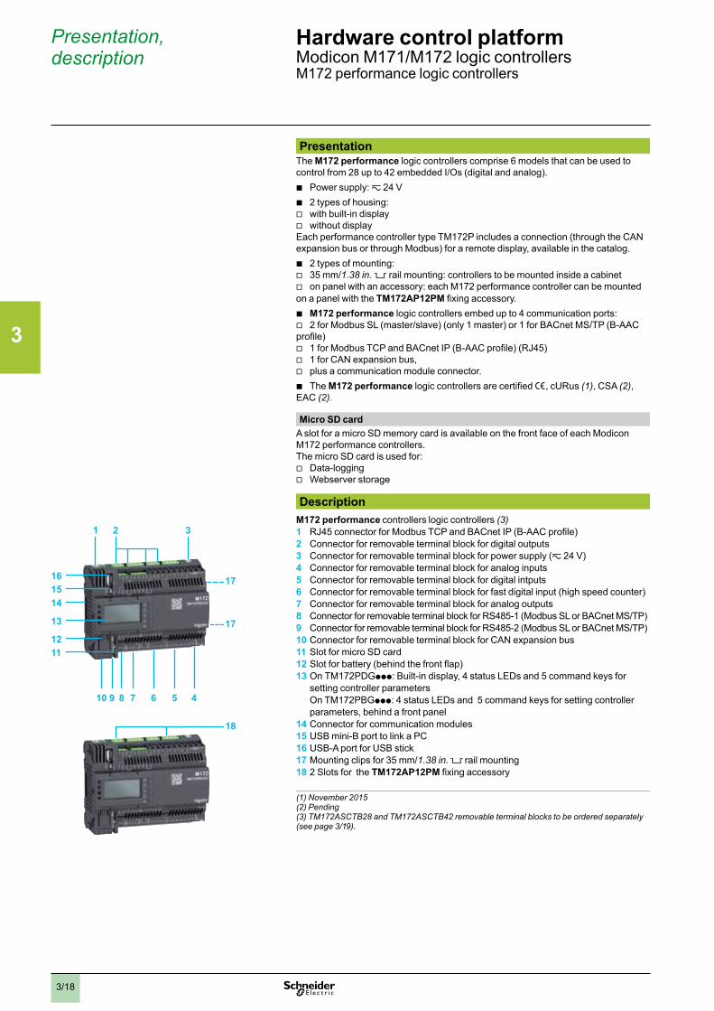
3/18
Presentation, description
Hardware control platformModicon M171/M172 logic controllersM172 performance logic controllers
PresentationThe M172 performance logic controllers comprise 6 models that can be used to control from 28 up to 42 embedded I/Os (digital and analog).
b Power supply: z 24 V b 2 types of housing: v with built-in display v without display
Each performance controller type TM172P includes a connection (through the CAN expansion bus or through Modbus) for a remote display, available in the catalog.
b 2 types of mounting: v 35 mm/1.38 in. 5 rail mounting: controllers to be mounted inside a cabinet v on panel with an accessory: each M172 performance controller can be mounted
on a panel with the TM172AP12PM fixing accessory. b M172 performance logic controllers embed up to 4 communication ports: v 2 for Modbus SL (master/slave) (only 1 master) or 1 for BACnet MS/TP (B-AAC
profile) v 1 for Modbus TCP and BACnet IP (B-AAC profile) (RJ45) v 1 for CAN expansion bus, v plus a communication module connector. b The M172 performance logic controllers are certified e, cURus (1), CSA (2),
EAC (2).
Micro SD cardA slot for a micro SD memory card is available on the front face of each Modicon M172 performance controllers. The micro SD card is used for:
v Data-logging v Webserver storage
DescriptionM172 performance controllers logic controllers (3)1 RJ45 connector for Modbus TCP and BACnet IP (B-AAC profile) 2 Connector for removable terminal block for digital outputs3 Connector for removable terminal block for power supply (z 24 V)4 Connector for removable terminal block for analog inputs5 Connector for removable terminal block for digital intputs6 Connector for removable terminal block for fast digital input (high speed counter)7 Connector for removable terminal block for analog outputs8 Connector for removable terminal block for RS485-1 (Modbus SL or BACnet MS/TP)9 Connector for removable terminal block for RS485-2 (Modbus SL or BACnet MS/TP)10 Connector for removable terminal block for CAN expansion bus11 Slot for micro SD card12 Slot for battery (behind the front flap)13 On TM172PDGppp: Built-in display, 4 status LEDs and 5 command keys for
setting controller parameters On TM172PBGppp: 4 status LEDs and 5 command keys for setting controller parameters, behind a front panel
14 Connector for communication modules15 USB mini-B port to link a PC16 USB-A port for USB stick17 Mounting clips for 35 mm/1.38 in. rail mounting 18 2 Slots for the TM172AP12PM fixing accessory
(1) November 2015(2) Pending(3) TM172ASCTB28 and TM172ASCTB42 removable terminal blocks to be ordered separately (see page 3/19).
18
1 2 3
45678
1112
13
141516 17
17
910
2
1
3
4
5
6
7
8
9
10
2
1
3
4
5
6
7
8
9
10
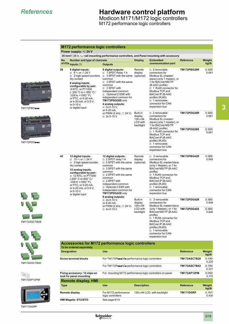
3/19
References Hardware control platformModicon M171/M172 logic controllersM172 performance logic controllers
M172 performance logic controllersPower supply: z 24 V 35 mm/1.38 in . 5 rail mounting performance controllers, and Panel mounting with accessoryNo. of I/Os
Number and type of channels Display Embedded communication port
Reference Weightkg/lbInputs (1) Outputs
28 8 digital inputs: v 6 a or c 24 V v 2 high speed counters,
dry contact8 analog inputs, configurable by pair: 8 NTC, or PT1000 (- 200 °C to + 850 °C/-328 to +1562 °F), or PTC, or 0-20 mA , or 4-20 mA, or 0-5 V, or 0-10 V, or digital input
8 digital outputs: v 1 SPDT Relay 1 A v 3 SPST with the same
common v 2 SPST with the same
common v 2 SPST with
independent common v Optional 2 SSR with
independent common for TM172PDG28S only4 analog outputs:
v 2x 0-10 V, or 4-20 mA, or PWM (2 kHz, c 24 V)
v 2x 0-10 V
Remote display (optional)
v 2 removable connectors for Modbus SL (master/slave) (only 1 master), or 1 for BACnet MS/TP (B-AAC profile)
v 1 RJ45 connector for Modbus TCP and BACnet IP (B-AAC profile) (RJ45)
v 1 removable connector for CAN expansion bus
TM172PBG28R 0.300/0.661
Built-in display 128 x 64 LCD with backlight
v 2 removable connectors for Modbus SL (master/slave) (only 1 master), or 1 for BACnet MS/TP (B-AAC profile)
v 1 RJ45 connector for Modbus TCP and BACnet IP (B-AAC profile) (RJ45)
v 1 removable connector for CAN expansion bus
TM172PDG28R 0.300/0.661
TM172PDG28S 0.300/0.661
42 12 digital inputs: v 10 a or c 24 V v 2 high speed counter,
dry contact12 analog inputs, configurable by pair:
v 12 NTC, or PT1000 (-200° C to 850° C/-328 to +1562 °F), or PTC, or 0-20 mA, or 4-20 mA, or 0-5 V, or 0-10 V, or digital input
12 digital outputs: v 2 SPDT relay 1 A v 3 SPST with the same
common v 3 SPST with the same
common v 2 SPST with the same
common v 2 SPST with
independent common v Optional 2 SSR with
independent common for TM172PDG42S only6 analog outputs:
v 2x 0-10 V, or 4-20 mA, or PWM (2 kHz, c 24 V)
v 4x 0-10 V
Remote display (optional)
v 2 removable connectors for Modbus SL master/slave (only 1 Master), or 1 for BACnet MS/TP (B-AAC profile)
v 1 RJ45 connector for Modbus TCP and BACnet IP (B-AAC profile) (RJ45)
v 1 removable connector for CAN expansion bus
TM172PBG42R 0.385/0.849
Built-in display 128 x 64 LCD with backlight
v 2 removable connectors for Modbus SL master/slave (only 1 Master), or 1 for BACnet MS/TP (B-AAC profile)
v 1 RJ45 connector for Modbus TCP and BACnet IP (B-AAC profile) (RJ45)
v 1 removable connector for CAN expansion bus
TM172PDG42R 0.385/0.849
TM172PDG42S 0.385/0.849
Accessories for M172 performance logic controllersTo be ordered separatelyDesignation Use Reference Weight
kg/lbScrew terminal blocks For TM172Pppp28p performance logic controllers TM172ASCTB28 0.100/
0.220For TM172Pppp42p performance logic controllers TM172ASCTB42 0.150/
0.331Fixing accessory: 12 clips-on lock for panel mounting
For mounting M172 performance logic controllers on panel TM172AP12PM 0.050/0.110
Remote display, HMIType Use Description Reference Weight
kg/lbRemote display For M172 performance
logic controllers128 x 64 LCD, with backlight TM171DGRP 0.197/
0.430HMI Magelis STU/STO See page 6/14
TM171DGRP
TM172ASCTB42
TM172ASCTB28
TM172PBGppp
TM172PDGppp
TM172AP12PM
2
1
3
4
5
6
7
8
9
10
2
1
3
4
5
6
7
8
9
10
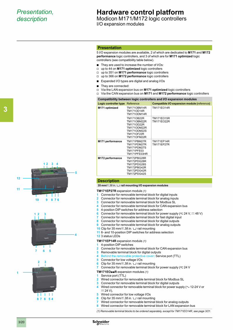
3/20
Presentation, description
Hardware control platformModicon M171/M172 logic controllersI/O expansion modules
Presentation5 I/O expansion modules are available, 2 of which are dedicated to M171 and M172 performance logic controllers, and 3 of which are for M171 optimized logic controllers (see compatibility table below).
b They are used to increase the number of I/Os: v up to 44 on M171 optimized logic controllers v up to 351 on M171 performance logic controllers v up to 366 on M172 performance logic controllers b Expanded I/O types are digital and analog I/Os b They are connected: v Via the LAN expansion bus on M171 optimized logic controllers v Via the CAN expansion bus on M171 and M172 performance logic controllers
Compatibility between logic controllers and I/O expansion modulesLogic controller type Reference Compatible I/O expansion module (reference)M171 optimized TM171OBM14R
TM171OD14R TM171ODM14R
TM171EO14R
TM171OB22R TM171OBM22R TM171OD22R TM171ODM22R TM171ODM22S TM171OF22R TM171OFM22R
TM171EO15R TM171EO22R
M171 performance TM171PBM27R TM171PDM27R TM171PDM27S TM171PFE03 TM171PFE03HR
TM171EP14R TM171EP27R
M172 performance TM172PBG28R TM172PDG28R TM172PDG28S TM172PBG42R TM172PDG42R TM172PDG42S
Description35 mm/1.38 in . 5 rail mounting I/O expansion modules
TM171EP27R expansion module (1)1 Connector for removable terminal block for digital inputs2 Connector for removable terminal block for analog inputs3 Connector for removable terminal block for Modbus SL4 Connector for removable terminal block for CAN expansion bus5 4-position DIP switches for address selection6 Connector for removable terminal block for power supply (z 24 V, c 48 V)7 Connector for removable terminal block for fast digital input8 Connector for removable terminal block for digital outputs9 Connector for removable terminal block for analog outputs10 Clip for 35 mm/1.38 in. 5 rail mounting11 6- and 10-position DIP switches for address selection12 3 status LEDsTM171EP14R expansion module (1)1 4-position DIP switches2 Connector for removable terminal block for CAN expansion bus3 Removable terminal block for digital outputs4 Behind the removable protective cover: Service port (TTL)5 Connector for low voltage I/Os6 Clip for 35 mm/1.38 in. 5 rail mounting7 Connector for removable terminal block for power supply (z 24 VTM171EOppR expansion modules (1)1 Service port (TTL)2 Wired connector for removable terminal block for Modbus SL3 Connector for removable terminal block for digital outputs4 Wired connector for removable terminal block for power supply (a 12-24 V or
c 24 V),5 Wired connector for low voltage I/Os6 Clip for 35 mm/1.38 in. 5 rail mounting7 Wired connector for removable terminal block for analog outputs8 Wired connector for removable terminal block for LAN expansion bus
(1) Removable terminal blocks to be ordered separately, except for TM171EO14R, see page 3/21.
10
1 2 3 4
6789
11
5
12
1 2 3
567
4
8 4567
1
2 3
2
1
3
4
5
6
7
8
9
10
2
1
3
4
5
6
7
8
9
10
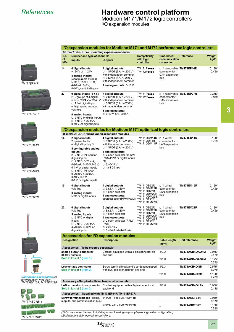
3/21
References Hardware control platformModicon M171/M172 logic controllersI/O expansion modules
I/O expansion modules for Modicon M171 and M172 performance logic controllers 35 mm/1.38 in . 5 rail mounting expansion modulesNo. of I/Os
Number and type of channels Compatibility with logic controller
Embedded communication connection
Reference Weightkg/lbInputs Outputs
14 4 digital inputs:a 24 V or c 24V4 analog inputs:(configurable by pair)NTC, PT1000, PTC,4-20 mA, 0-5 V,0-10 V, or digital inputs
4 digital outputs: v 1 SPDT (5 A, a 230 V)
with independent common v 3 SPST (3 A, a 230 V)
with independent common2 analog outputs: 0-10 V
TM171PppppTM172Ppppp
v 1 removable connector for CAN expansion bus
TM171EP14R 0.190/0.420
27 9 digital inputs (8 + 1): v 2 groups of 4 digital
inputs, z 24 V or c 48 V v 1 fast digital input
or high speed counter, volt-free
6 analog inputs: v 2 NTC or digital inputs v 4 NTC, 4-20 mA,
0-10 V, or digital inputs
7 digital outputs: v 2 SPDT (8 A, a 230 V)
with independent common v 5 SPST (5 A, a 230 V)
with independent common5 analog outputs:
v 0-10 V, or 4-20 mA
TM171PppppTM172Ppppp
v 1 removable connector for CAN expansion bus
TM171EP27R 0.385/0.850
I/O expansion modules for Modicon M171 optimized logic controllers35 mm/1.38 in . 5 rail mounting expansion modules
14 2 digital inputs:2 open collectoror digital inputs (1)5 configurable analog inputs:
v 2 NTC, PT1000 or digital inputs
v 2 NTC, 0-20 mA, 4-20 mA, 0-10 V, 0-5 V, 0-1 V, or digital inputs
v 1 NTC, PT1000, 0-20 mA, 4-20 mA, 0-10 V, 0-5 V, 0-1 V, or digital inputs
4 digital outputs: v 3 SPST (2 A, a 230 V)
with the same common v 1 SPDT (2 A, a 230 V)
5 analog outputs: v 2 open collector for 12 V
PWM/PPM or digital inputs (1)
v 2x 0-10 V v 1x 4-20 mA
TM171OBM14RTM171OD14RTM171ODM14R
v 1 wired connector for LAN expansion bus
TM171EO14R 0.190/0.420
15 6 digital inputs:volt-free3 analog inputs:NTC or digital inputs
4 digital outputs: v 3x 2 A, a 250 V v 1 open collector
2 analog outputs:open collector (PPM/PWM)
TM171OB22RTM171OBM22RTM171OD22RTM171ODM22RTM171ODM22STM171OF22RTM171OFM22R
v 1 wired connector for LAN expansion bus
TM171EO15R 0.190/0.420
22 6 digital inputs:volt-free5 analog inputs:
v 3 NTC or digital inputs
v 2 NTC, 0-20 mA, 4-20 mA, 0-10 V, or digital inputs
6 digital outputs: v 5x 2 A, a 250 V v 1 open collector
5 analog outputs: v 2 open collector (PPM/
PWM) v 2x 0-10 V v 1x 0-20 mA/4-20 mA
TM171OB22RTM171OBM22RTM171OD22RTM171ODM22RTM171ODM22STM171OF22RTM171OFM22R
v 1 wired connector for LAN expansion bus
TM171EO22R 0.190/0.420
Accessories for I/O expansion modulesDesignation Description Cable length
(m/ft .)Unit reference Weight
kg/lbAccessories – To be ordered separately
analog output connector(0-10 V outputs)Sold in lots of 5 (item 1)
Cordset equipped with a 4-pin connector on one end
1/3.3 TM171ACB4OAO1M 0.075/ 0.170
2/6.6 TM171ACB4OAO2M 0.125/0.280
Low voltage connectorSold in lots of 5 (item 2)
Screw terminal block and a cordset equipped with a 20-pin connector on one end
1/3.3 TM171ACB4OI1M 0.575/1.270
2/6.6 TM171ACB4OI2M 1.120/ 2.470
Accessory – Supplied with each expansion moduleLAN expansion bus connectorSold in lots of 5 (item 3)
Cordset equipped with a 3-pin connector at each end
2/6.6 TM171ACB4OLAN 0.060/0.130
Accessories – Supplied with TM171EP14R TM171EP27RScrew terminal blocks (inputs, outputs, and communication bus)
14 I/Os – For TM171EP14R _ TM171ASCTB14 0.050/0.110
27 I/Os – For TM171EP27R _ TM171ASCTB27 0.100/0.220
(1) On the same channel: 2 digital inputs or 2 analog outputs (depending on the configuration).(2) Minimum set for operating controllers.
TM171EP14R
TM171EP27R
TM171EO14R
TM171EO15R
TM171EO22R
TM171ASCTB14
TM171ASCTB27
2
3
1
Connection accessories (2) for expansion modules: TM171EO15R, M171EO22R
2
1
3
4
5
6
7
8
9
10
2
1
3
4
5
6
7
8
9
10
3/22
Presentation, description
Hardware control platformModicon M171/M172 logic controllersCommunication modules for M171 performance and M172 performance logic controllers
PresentationThe communication module offer is dedicated to the 35 mm/1.38 in. rail mounting version of M171 performance and M172 performance logic controllers (1).The 8 optional modules provide specific connections:
b To fieldbuses, including: v CAN bus v Modbus TCP v Profibus v Modbus SL (RS 485) v BACnet MS/TP (B-AAC profile) v BACnet IP (B-AAC profile) v RS 232 serial link v LonWorks (FFT-10) v Konnex (KNX) via Schneider Electric’ spaceLYnk gateway, see page 5/5 b To services, including: v Ethernet v WebVisu and remote download functions b They are mounted by simple interlocking on the left-hand side of an M171
performance or an M172 performance logic controller (1). b Only one communication module can be added to a performance logic controller.
The communication module is powered by the controller. b Each communication module has its own type of connector, adapted to the bus
or communication network (see details in the reference table, page 3/23).
Description 35 mm/1.38 in . rail mounting
TM171Apppp I/O communication modules1 Communication connector (2)2 Locking device3 Expansion connector to the performance controller type TM171P or TM172P (1)4 Clip for 35 mm/1.38 in. rail mounting
(1) Compatibility between M171 and M172 performance logic controllers and communication modules, see table below:
Compatibility between performance logic controllers and communication modulesLogic controller Compatible communication
modulesType ReferenceM171 performance logic controller
TM171PBM27RTM171PDM27RTM171PDM27S
TM171ACANTM171AETHTM171APBUSTM171AMBTM171ARS485TM171ARS232TM171AETHRS485TM171ALON
M172 performance logic controller
TM172PBG28RTM172PDG28RTM172PDG28STM172PBG42RTM172PDG42RTM172PDG42S
TM171ACANTM171AMBTM171ARS485TM171ARS232TM171ALON
(2) Communication connector type depends on communication modules, see detail next page.
4
3
2
2
2
1
1
1
2
1
3
4
5
6
7
8
9
10
2
1
3
4
5
6
7
8
9
10

3/23
References Hardware control platformModicon M171/M172 logic controllersCommunication modules for M171 performance and M172 performance logic controllers
Communication modulesFor M171 and M172 performance logic controllers (35 mm/1.38 in . rail mounting version)Designation Compatibility with
logic controllerFieldbus, services access
Communication port Reference(1)
Weightkg/lb
Communication modules M171 performance, M172 performance
v CAN v 2 screw terminal blocks (1)
TM171ACAN 0.077/0.170
M171 performance v Modbus TCP v Ethernet v BACnet IP (B-AAC
profile) v WebVisu and remote
download functions
v 1 RJ45 TM171AETH 0.077/0.170
M171 performance v Profibus v 1 SUB-D 9 TM171APBUS 0.077/0.170
M171 performance, M172 performance
v Modbus SL (RS 485) v 2 screw terminal blocks (1)
TM171AMB 0.077/0.170
M171 performance, M172 performance
v Modbus SL or BACnet MS/TP (B-AAC profile)
v 2 screw terminal blocks (1)
TM171ARS485 0.077/0.170
M171 performance, M172 performance
v RS 232 serial link v Relay output
v 1 SUB-D 9 for RS 232
v 1 screw terminal block for relay output (1)
TM171ARS232 0.077/0.170
M171 performance v Modbus TCP and BACnet/IP
v Modbus SL or BACnet MS/TP (B-AAC profile)
v WebVisu and remote download functions
v Ethernet
v 1 RJ45 for Ethernet v 2 screw terminal
blocks for RS 485 (1)
TM171AETHRS485 0.077/0.170
M171 performance, M172 performance
v LonWorks (FFT-10) v 1 screw terminal block for LON bus
TM171ALON 0.077/0.170
(1) Removable terminal blocks supplied with communication modules.
TM171AETH
TM171APBUS
TM171AMB
TM171ARS485
TM171ARS232
TM171AETHRS485
TM171ACAN
TM171ALON
2
1
3
4
5
6
7
8
9
10
2
1
3
4
5
6
7
8
9
10
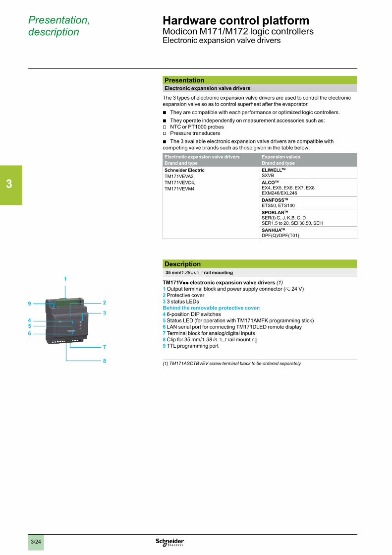
3/24
Presentation, description
Hardware control platformModicon M171/M172 logic controllersElectronic expansion valve drivers
PresentationElectronic expansion valve drivers
The 3 types of electronic expansion valve drivers are used to control the electronic expansion valve so as to control superheat after the evaporator.
b They are compatible with each performance or optimized logic controllers. b They operate independently on measurement accessories such as: v NTC or PT1000 probes v Pressure transducers b The 3 available electronic expansion valve drivers are compatible with
competing valve brands such as those given in the table below:
Electronic expansion valve driversBrand and type
Expansion valvesBrand and type
Schneider ElectricTM171VEVA2,TM171VEVD4,TM171VEVM4
ELIWELLTM
SXVBALCOTM
EX4, EX5, EX6, EX7, EX8EXM246/EXL246DANFOSSTM
ETS50, ETS100SPORLANTM
SER(I) G, J, K,B, C, DSER1.5 to 20, SEI 30,50, SEHSANHUATM
DPF(Q)/DPF(T01)
Description 35 mm/1.38 in . rail mounting
TM171Vpp electronic expansion valve drivers (1)1 Output terminal block and power supply connector (z 24 V)2 Protective cover3 3 status LEDsBehind the removable protective cover:4 6-position DIP switches5 Status LED (for operation with TM171AMFK programming stick)6 LAN serial port for connecting TM171DLED remote display7 Terminal block for analog/digital inputs8 Clip for 35 mm/1.38 in. rail mounting9 TTL programming port
(1) TM171ASCTBVEV screw terminal block to be ordered separately.8
7
9
1
3
2
456
2
1
3
4
5
6
7
8
9
10
2
1
3
4
5
6
7
8
9
10
3/25
References Hardware control platformModicon M171/M172 logic controllersElectronic expansion valve drivers
TM171VEVA2
TM171VEVD4
TM171VEVM4
TM171ASCTBVEV
Electronic expansion valve driversApplication Number and type of channels Reference Weight
kg/lbInputs OutputsActuator, convert 0-10 V or 4-20 mA in opening position contact
1 analog input: v 1x 4-20 mA, 0-5 V, or 0-10V
1 digital output: v 1 open collector
(100 mA, c 12 V)
TM171VEVA2 0.190/0.420
Autonomous, wired to manage On/Off contact
2 digital inputs: v 2 volt-free
4 analog inputs: v 2 NTC
(-50…+110 °C, -40…+150 °C /-58…+203 °F, -40…+302 °F), PT1000, 4-20 mA, 0-5 V, or 0-10 V
v 2 NTC (-50…+110 °C, -40…+150 °C /-58…+203 °F, -40…+302 °F),or PT1000 (1)
2 digital outputs: v 1 open collector
(100 mA, c 12 V) v 1 SPST NO relay contact,
5 A, a 250 V
TM171VEVD4 0.190/0.420
Autonomous, managed by Modbus (RS 485)
2 digital inputs: v 2 volt-free
4 analog inputs: v 2 NTC
(-50…+110 °C, -40…+150 °C/ -58…+203 °F, -40…+302 °F),PT1000, 4-20 mA, 0-5 V, or 0-10 V (1)
v 2 NTC (-50…+110 °C, -40…+150 °C/ -58…+203 °F, -40…+302 °F),or PT1000 (1)
2 digital outputs: v 1 open collector
(100 mA, c 12 V) v 1 SPST NO relay contact,
5 A, a 250 V
TM171VEVM4 0.190/0.420
Accessories for Electronic expansion valve driversTo be ordered separatelyDesignation For connecting Reference Weight
kg/lbScrew terminal block for electronic expansion valve drivers
Power supply, sensor power supply, digital and analog I/O, Modbus link
TM171ASCTBVEV 0.050/0.110
(1) 2 PT1000 (-50…+99.9 ° C / -58… + 211.82 °F)
2
1
3
4
5
6
7
8
9
10
2
1
3
4
5
6
7
8
9
10
3/26
References Hardware control platformModicon M171/M172 logic controllersMeasurement accessories
Measurement accessoriesApplication Description Sold in
lots of Cablelengthm/ft .
Unit reference Weightkg/lb
Humidity & temperature probe
v IP 65 v 4-20 mA v Wall mounting v Measuring ranges: 0…100%,
- 40…60 °C / -40...140 °F
– – TM1SH314 0.176/0.390
Humidity probe v IP 65 v 4-20 mA v Wall mounting v Measuring ranges: 0…100%
– – TM1SH304 0.170/0.370
Humidity probe (sensor equipped with a cable)
v IP 54 v 4-20 mA v Measuring ranges: 15…90%
– 3/9.84 TM1SH284 0.138/0.300
NTC probes (sensor equipped with a cable)
v IP 67 v Sensor 6x 15 mm / 0,591 in. v -50…+110 °C/-122…+230 °F v Grey
8 1.5/4.92 TM1STNTCRN61515 0.104/0.230
5 3/9.84 TM1STNTCRN61530 0.125/0.280
4 5/16.40 TM1STNTCRN61550 0.164/ 0.360
v FAST IP 67 v 4x 40 mm / 1.57 in. v -50…+110 °C/-122…+230 °F v Grey
8 1.5/4.92 TM1STNTCSF44015 0.144/0.320
5 3/9.84 TM1STNTCSF44030 0.175/0.390
v IP 68 v 6x 20 mm / 0,79 in. v -50…+110 °C/-122…+230 °F v Grey
8 1.5/4.92 TM1STNTCSN62015 0.144/0.320
5 3/9.84 TM1STNTCSN62030 0.175/0.390
4 5/16.40 TM1STNTCSN62050 0.232/ 0.510
v IP 68 v 6x 20 mm / 0,79 in. v TPE v with strap v Grey
8 1.5/4.92 TM1STNTCTN62015 0.152/0.340
5 3/9.84 TM1STNTCTN62030 0.180/ 0.400
v IP 68 v 5x 20 mm / 0,79 in. v -50…+110 °C/-122…+230 °F v Grey
8 1.5/4.92 TM1STNTCRN52015 0.144/0.320
5 3/9.84 TM1STNTCRN52030 0.180/ 0.400
4 5/16.40 TM1STNTCRN52050 0.228/0.500
NTC probes for air wall mounting
v Outdoor mounting – – TM1STNTCWN65605 0.050/0.110
v Indoor mounting – – TM1STNTCWN75750 0.050/0.110
PT1000 probes v IP 68 v 6x 20 mm / 0,79 in. v -50…+110 °C/-122…+230 °F v Green
8 1.5/4.92 TM1STPTTSN62015 0.144/0.320
5 3/9.84 TM1STPTTSN62030 0.175/0.390
v IP 68 v 5x 20 mm / 0,79 in. v -50…+110 °C/-122…+230 °F v Green
8 1.5/4.92 TM1STPTTSN52015 0.136/0.300
5 3/9.84 TM1STPTTSN52030 0.175/0.390
4 5/16.40 TM1STPTTSN52050 0.232/0.510
TM1STNTCWN65605pp
TM1SH284
TM1SH3p4
TM1STNTCRN615pp
TM1STNTCSF440pp
TM1STNTCTN620pp
TM1STPTTSN620pp
TM1STPTTSN520pp
TM1STNTCRN520pp
TM1STNTCWN75750pp
TM1STNTCSN620pp
2
1
3
4
5
6
7
8
9
10
2
1
3
4
5
6
7
8
9
10
3/27
Presentation Hardware control platformModicon M171/M172 logic controllersMeasurement accessories
Schneider Electric recommends his partner Telemecanique Sensors, which proposes a range of pressure transmitters: XMLP
PresentationXMLP pressure transmitters are characterised by their “thin film” technology. The stainless steel capsule holding the sensing element is welded directly onto the transmitter’s stainless steel body, which provides the following advantages: > No gasket comes into contact with the fluid > Compatibility with a large number of fluids:
- Hydraulic oils - Air - Fresh water - Refrigeration fluids - All fluids or gases compatible with stainless steel AISI 304
XMLP pressure transmitters can control fluids from - 30 to 120°C / 86 to 248 °F. Their power supply depends on the type of analog output: > 5 V +/- 5% for the 0.5…4.5 V ratiometric output > 12 or 24 V (nominal), operating from 8 to 30 V for the 4…20 mA output > 24 V (nominal), operating from 14 to 30 V for the 0…10 V output
Made of 304 stainless steel, XMLP pressure transmitters are compact and rugged. Their degree of protection varies according to the type of connector: > IP 65 for versions with connector EN 175301-803-A > IP 65 and IP 67 for Packard Metri-Pack connector versions > IP 65, IP 67 and IP 69K for M12 connector versions
With typical precision better than 0.5% of the rating, these transmitters are particularly suitable for industrial applications such as: > Machine tools > Moulding presses > Stamping presses > Lifting gear > Air-conditioning systems (HVAC)
FunctionsXMLP pressure transmitters have an analog output which delivers a signal proportional to the measured pressure. This output can be one of the following types: > 4…20 mA > 0…10 V > 0.5…4.5 V
The pressure ranges available are: > 0…10 bar to 0…600 bar or > 0…100 psi to 0…10,000 psi
The XMLP offer is available in three types of electrical connection: > M12, 4-pin connector > EN 175301-803-A connector (ex-DIN 43650) > Packard Metri-Pack 150 connector
Several types of fluid connection are available: > G1/4 A male > SAE 7/16-20UNF-2A male > SAE 7/16-20UNF-2B female (with Schrader pin) > 1/4”-18 NPT male
Nota: XMLP pressure transmitters are sold individually or in lots of 40.
> Discover XMLP offer on the web site: http://www.tesensors.com/global > Access to the catalog by product at this URL: http://www.tesensors.com/global/en/product/catalog/
XMLP pressure transmitters
2
1
3
4
5
6
7
8
9
10
2
1
3
4
5
6
7
8
9
10

Chapter 4Programming software
b Technical data relating to products listed in this chapter is available online at www.schneider-electric.com/modicon-m171-m172

2
1
3
4
5
6
7
8
9
10
4/1
b SoMachine HVAC programming software for Modicon M171/M172 logic controllers
v Presentation . . . . . . . . . . . . . . . . . . . . . . . . . . . . . . . . . . . . . . . . . . . . . . page 4/2
v General characteristics . . . . . . . . . . . . . . . . . . . . . . . . . . . . . . . . . . . . . page 4/2
v Product offer . . . . . . . . . . . . . . . . . . . . . . . . . . . . . . . . . . . . . . . . . . . . . . page 4/3
v References > Programming Software ......................................................................... page 4/3 > Programming accessories: - for M171 and M172 performance logic controllers ......................... page 4/3 - for M171 optimized logic controllers .............................................. page 4/3
Contents Modicon M171/M172 logic controllers for HVAC and Pumping solutions
4/1
4/2
Presentation Programming software SoMachine HVAC programming softwarefor Modicon M171/M172 logic controllers
SoMachine HVAC programming software
PresentationSoftware solution
SoMachine HVAC programming software is compliant with IEC 61131-3. It can be used to develop, configure, and commission entire HVAC or Pumping solution systems.
It includes: b Programming Modicon M171/M172 logic controllers (performance and
optimized) and remote display units b Setting up expansion buses and networks b Creating the screen of the displays (built-in and displays of the M171/M172 logic
controller offer) b Configuring BMS communication modules on BACnet MS/TP (B-AAC profile), Modbus
SL, Modbus TCP, BAcnet MS/TP, BACnet IP (B-AAC profile), and LonWorks (FFT-10) b Dedicated libraries such as: v a library of application function blocks (1) v a library of Tested, Validated, and Documented Applications (TVDA) b Full simulation mode
General characteristicsOverview
Programming languages b ST (Structured Text) b FBD (Function Block Diagram) b LD (Ladder) b IL (Instruction List) b SFC (Sequential Function Chart)
Applications b Graphical and text-based languages: v Adaptation to each developer background v Library management v Code debugging v Parameter definition v Simulation mode b Advanced programming: v Vectors v Pointers
System solutions management b Multi-target project b Management of Modbus data b Data exchange between several Modicon M171/M172 performance logic controllers
Graphical user interface b Graphic display: v Multipage v Buttons v Edit box v Static text v Images v Animations v Bars v Lists of data (parameters/variables/alarms) b Configurable buttons b Multilanguage b Automatic documentation
Communication bus configurators b Control networks: Modbus TCP, Modbus SL, Profibus b Expansion bus fieldbus: CAN expansion bus b BMS connectivity: BACnet MS/TP (B-AAC profile), BACnet IP (B-AAC profile), LonWorks
(FFT-10)
Advanced simulation options b Full simulation v I/O emulation v HMI v IEC code v Live debug v Triggers v Oscilloscope
Advanced debugging and simulation options b Remote control/download: v Modbus SL & TCP v CAN v Modem b Parameter management b Status monitoring b Field test: v Oscilloscope v Debug window v Export to Excel
(1) For more information about Application Function Blocks, see chapter 2.
2
1
3
4
5
6
7
8
9
10
2
1
3
4
5
6
7
8
9
10

4/3
References Programming software SoMachine HVAC programming softwarefor Modicon M171/M172 logic controllers
Product offerSoMachine HVAC software is supplied on a DVD or can be downloaded from our web site: www.schneider-electric.com > Solutions > Systems > Machine Control > HVAC control.The product version concerned offers the SoMachine HVAC functions associated with logic controllers.
ReferencesSystem configuration:
b Processor: Pentium 1.6 GHz or higher b RAM: 1 GB; 2 GB recommended b Hard disk: 500 MB minimum b OS: 32-bit Windows; XP Pro SP3 or Windows 7 (32-bit or 64-bit) or Windows 8 b Drive: DVD drive b Display: SVGA video card; 800×600, 128 MB; 1024×768, 256 MB recommended b Peripheral device: A mouse or compatible pointing device b Peripheral device: USB interface
SoMachine HVAC programming softwareApplication Reference Weight
kg/lbM171 optimized logic controllers, M171 performance logic controllers, and M172 performance logic controllers
TM171SW 0.050/0.110
Programming accessories for M171 and M172 performance logic controllers b The USB cable is recommanded for local programmation. b Ethernet port is recommanded for remote download or remote programmation.
Description Characteristics and use Lengthm/ft .
Reference Weightkg/lb
Programming through USB portProgramming cables (1)
From the PC USB-A port to the USB mini-B port on M171 (2) and M172 performance logic controllers (2)
3/0.98 TCSXCNAMUM3P(1)
0.065/ 0.143
1.8/5.90 BMXXCAUSBH018 0.065/ 0.143
Programming through Modbus SL and/or EthernetUSB to RS485 converter (3)
To be used on M171 (2) and M172 performance logic controllers (2)Equipped with 1 RJ45 connector on the controller side and 1 USB-A connector on the PC side
0.4/1.31 TSXCUSB485 0.144/0.320
Connection cable for Modbus serial link (4)
Equipped with 1 RJ45 connector at one end and flying leads at the other end
3/9.84 VW3A8306D30 0.250/0.550
Ethernet connection cableEthernet ConneXium cable - shielded twisted pair straight cord (5)e compatible
For connection to terminal devices (DTE) Equipped with 1 RJ45 connector at each end
2/6.56(2)
490NTW00002 –
(1) Unshielded cable without grounding. To be used only for temporary connections. For permanent connections, use the reference BMXXCAUSBH018.(2) Other length available: 5 m/16.40 ft, 12 m/39.37 ft, 40 m/131.23 ft, and 80 m/262.47 ft, see page 5/4.Programming accessories for M171 optimized logic controllersProgramming through TTL programming port Description Characteristics and use Reference Weight
kg/lbProgramming cable (6) To be used between a PC and the TTL
programming port of M171 optimized logic controllers (8)
TM171ADMI 0.157/0.350
Programming stick (7) To be used to transfer parameters from one M171 optimized logic controller (8) to another, or to download the program
TM171AMFK 0.010/0.020
Programming through USB port USB to RS485 converter (3) See aboveConnection cable for Modbus serial link (4) See above
USB
TTL
8
6
7
Local programming, download - M171 optimized - through TTL port
8
45
Remote programming - M171 optimized
Modbus SL
USB
2
34
Ethernet connection
Remote programming - M171 performance
Modbus SL
USB 5
Modbus SL
Modbus SL
2
1
Local programming, download - M171 & M172 performance - through USB port
USB
USB
2
34
Ethernet connection
Remote programming - M172 performance
Modbus SL
USB 5
Modbus SL
2
1
3
4
5
6
7
8
9
10
2
1
3
4
5
6
7
8
9
10

Chapter 5Connectivity
Technical data relating to products listed in this chapter is available online at www.schneider-electric.com
2
1
3
4
5
6
7
8
9
10
5/1
b MachineStruxure architectures . . . . . . . . . . . . . . . . . . page 5/2
b Communication modules for Modicon M171 and M172 performance logic controllers
v Presentation . . . . . . . . . . . . . . . . . . . . . . . . . . . . . . . . . . . . . . . . . . . . . . page 5/3
v References . . . . . . . . . . . . . . . . . . . . . . . . . . . . . . . . . . . . . . . . . . . . . . . page 5/3
b ConneXium - Connecting Ethernet devices: Shielded copper connection cables
v Presentation . . . . . . . . . . . . . . . . . . . . . . . . . . . . . . . . . . . . . . . . . . . . . . page 5/4
v References . . . . . . . . . . . . . . . . . . . . . . . . . . . . . . . . . . . . . . . . . . . . . . . page 5/4
b spaceLYnk gateway
v Presentation . . . . . . . . . . . . . . . . . . . . . . . . . . . . . . . . . . . . . . . . . . . . . . page 5/5
v References . . . . . . . . . . . . . . . . . . . . . . . . . . . . . . . . . . . . . . . . . . . . . . . page 5/5
b Universal automation Wifi interface
v Presentation . . . . . . . . . . . . . . . . . . . . . . . . . . . . . . . . . . . . . . . . . . . . . . page 5/5
v References . . . . . . . . . . . . . . . . . . . . . . . . . . . . . . . . . . . . . . . . . . . . . . . page 5/5
b WebVisu . . . . . . . . . . . . . . . . . . . . . . . . . . . . . . . . . . . . . . . . . . . . . . . . . . page 5/6
b StruxureWare application . . . . . . . . . . . . . . . . . . . . . . . . . . . . . . . page 5/7
Contents Modicon M171/M172 logic controllers for HVAC and Pumping solutions
5/1

5/2
Presentation ConnectivityModicon M171/M172 logic controllersMachineStruxure architectures
Easy integration into Building Management System (BMS)Your customers demand comprehensive solutions that include enterprise-wide management of power, IT, HVAC, Pumping, and security and with a level of efficiency that includes system dynamics across segments, platforms, and providers. That’s why MachineStruxureTM architectures can be easily integrated.
Modicon M171/M172, logic controllers for booster stations
Modbus TCP & BACnet/IProuter controller
Mod
bus
TCP,
BAC
net M
S/T
P &
BAC
net/I
PAltivar 61 variablespeed drive forpumps and fans
HVAC machinecontrol solutions
Building Management SystemServerCyberStation BACnet/IP:
Operator workstation + Server
Modbus TCP & BACnet/IProuter controller
BACnet MS/TP router controller Access controller
>>> 2...8 doors
Digital Sentry andVideo ManagementSystems
Third-Party interfacesvia Modbus SL,BACnet/IP,proprietary protocols
Third-Partyinterfaces viaModbus SL,BACnet/IP,proprietaryprotocols
Networkcamera
Modicon M171/M172, Logic controllers for Air Handling Unit
Modicon M171logic controller
Mod
bus
TCP,
BAC
net M
S/T
P &
BAC
net/I
P
BAC
net M
S/TP
InfiN
et o
r Wire
less
InfiN
et
Modicon M171/M172, Logic controllers for chiller
Terminalcontroller
Variableair volumecontroller
Systemcontroller
Localcontroller
Localcontroller
Powercontroller
Fan coilcontroller
Altivar 61 variablespeed drive forpumps and fans
Mobile phone Web interface Smart device
HVAC buildingcontrol solutions
Building accesscontrol solutions
Building videocontrol solutions
Automatic gates and doors
Video cameras
Pumping boostercontrol solutions
Your benefits > Modicon M171/M172 makes it easy to integrate your machines into your customers’ BMS architectures > Compliance with open BMS standards:
> BACnet/IP, BACnet MS/TP (B-AAC profile), Modbus TCP, Modbus RTU, and LonWorks
> BACnet/IP & Modbus TCP Ethernet modules offering easy maintenance through embedded data logging, text e-mail, and web server
> Maintenance and monitoring efficiency > Provided on Ethernet modules, offering embedded data logging, e-mail notification, and web server capabilities
> Late-point configuration with Modicon M171/M172 interchangeable communication plug-in
MachineStruxure architectures
(Pending)
2
1
3
4
5
6
7
8
9
10
2
1
3
4
5
6
7
8
9
10
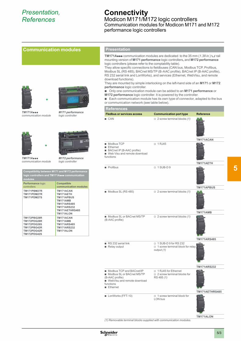
5/3
Presentation, References
ConnectivityModicon M171/M172 logic controllersCommunication modules for Modicon M171 and M172 performance logic controllers
Presentation
TM171Appp communication modules are dedicated to the 35 mm (1.38 in.) rail mounting version of M171 performance logic controllers, and M172 performance logic controllers (please refer to the comptability table). They allow specific connections to fieldbuses (CAN bus, Modbus TCP, Profibus, Modbus SL (RS 485), BACnet MS/TP (B-AAC profile), BACnet IP (B-AAC profile), RS 232 serial link and LonWorks), and services (Ethernet, WebVisu, and remote download functions). They are mounted by simple interlocking on the left-hand side of an M171 or M172 performance logic controller.
b Only one communication module can be added to an M171 performance or M172 performance logic controller. It is powered by the controller.
b Each communication module has its own type of connector, adapted to the bus or communication network (see table below).
ReferencesFIedbus or services access Communication port type Reference b CAN v 2 screw terminal blocks (1)
TM171ACAN b Modbus TCP b Ethernet b BACnet IP (B-AAC profile) b Web Visu and remote download
functions
v 1 RJ45
TM171AETH b Profibus v 1 SUB-D 9
TM171APBUS b Modbus SL (RS 485) v 2 screw terminal blocks (1)
TM171AMB b Modbus SL or BACnet MS/TP
(B-AAC profile) v 2 screw terminal blocks (1)
TM171ARS485 b RS 232 serial link b Relay output
v 1 SUB-D 9 for RS 232 v 1 screw terminal block for relay
output (1)
TM171ARS232 b Modbus TCP and BACnet/IP b Modbus SL or BACnet MS/TP
(B-AAC profile) b WebVisu and remote download
functions b Ethernet
v 1 RJ45 for Ethernet v 2 screw terminal blocks for
RS 485 (1)
TM171AETHRS485 b LonWorks (FFT-10) v 1 screw terminal block for
LON bus
TM171ALON(1) Removable terminal blocks supplied with communication modules.
+
TM171Appp communication module
M171 performance logic controller
Communication modules
Compatibility between M171 and M172 performance logic controllers and TM171Appp communication modulesPerformance logic controllers
Compatible communication modules
TM171PBM27RTM171PDM27RTM171PDM27S
TM171ACANTM171AETHTM171APBUSTM171AMBTM171ARS485TM171ARS232TM171AETHRS485TM171ALON
TM172PBG28RTM172PDG28RTM172PDG28STM172PBG42RTM172PDG42RTM172PDG42S
TM171ACANTM171AMBTM171ARS485TM171ARS232TM171ALON
+
TM171Appp communication module
M172 performance logic controller
2
1
3
4
5
6
7
8
9
10
2
1
3
4
5
6
7
8
9
10
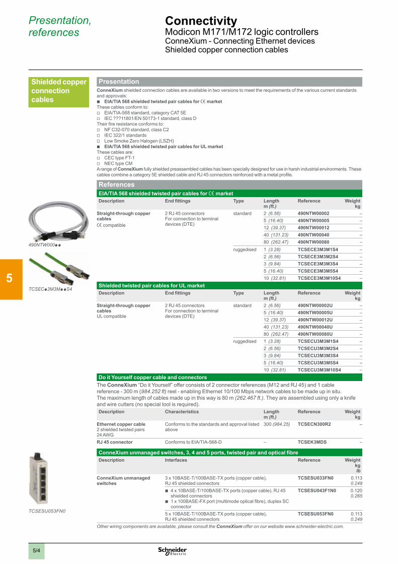
5/4
Presentation, references
ConnectivityModicon M171/M172 logic controllers ConneXium - Connecting Ethernet devicesShielded copper connection cables
PresentationConneXium shielded connection cables are available in two versions to meet the requirements of the various current standards and approvals:
b EIA/TIA 568 shielded twisted pair cables for e marketThese cables conform to:
v EIA/TIA-568 standard, category CAT 5E v IEC ???11801/EN 50173-1 standard, class D
Their fire resistance conforms to: v NF C32-070 standard, class C2 v IEC 322/1 standards v Low Smoke Zero Halogen (LSZH) b EIA/TIA 568 shielded twisted pair cables for UL market
These cables are: v CEC type FT-1 v NEC type CM
A range of ConneXium fully shielded preassembled cables has been specially designed for use in harsh industrial environments. These cables combine a category 5E shielded cable and RJ 45 connectors reinforced with a metal profile.
ReferencesEIA/TIA 568 shielded twisted pair cables for e marketDescription End fittings Type Length
m (ft .)Reference Weight
kgStraight-through copper cablese compatible
2 RJ 45 connectorsFor connection to terminal devices (DTE)
standard 2 (6.56) 490NTW00002 –5 (16.40) 490NTW00005 –12 (39.37) 490NTW00012 –40 (131.23) 490NTW00040 –80 (262.47) 490NTW00080 –
ruggedised 1 (3.28) TCSECE3M3M1S4 –2 (6.56) TCSECE3M3M2S4 –3 (9.84) TCSECE3M3M3S4 –5 (16.40) TCSECE3M3M5S4 –10 (32.81) TCSECE3M3M10S4 –
Shielded twisted pair cables for UL marketDescription End fittings Type Length
m (ft .)Reference Weight
kgStraight-through copper cablesUL compatible
2 RJ 45 connectorsFor connection to terminal devices (DTE)
standard 2 (6.56) 490NTW00002U –5 (16.40) 490NTW00005U –12 (39.37) 490NTW00012U –40 (131.23) 490NTW00040U –80 (262.47) 490NTW00080U –
ruggedised 1 (3.28) TCSECU3M3M1S4 –2 (6.56) TCSECU3M3M2S4 –3 (9.84) TCSECU3M3M3S4 –5 (16.40) TCSECU3M3M5S4 –10 (32.81) TCSECU3M3M10S4 –
Do it Yourself copper cable and connectorsThe ConneXium “Do it Yourself” offer consists of 2 connector references (M12 and RJ 45) and 1 cable reference - 300 m (984.252 ft) reel - enabling Ethernet 10/100 Mbps network cables to be made up in situ. The maximum length of cables made up in this way is 80 m (262.467 ft.). They are assembled using only a knife and wire cutters (no special tool is required).Description Characteristics Length
m (ft .)Reference Weight
kgEthernet copper cable2 shielded twisted pairs24 AWG
Conforms to the standards and approval listed above
300 (984.25) TCSECN300R2 –
RJ 45 connector Conforms to EIA/TIA-568-D – TCSEK3MDS –
ConneXium unmanaged switches, 3, 4 and 5 ports, twisted pair and optical fibreDescription Interfaces Reference Weight
kglb
ConneXium unmanaged switches
3 x 10BASE-T/100BASE-TX ports (copper cable), RJ 45 shielded connectors
TCSESU033FN0 0.1130.249
b 4 x 10BASE-T/100BASE-TX ports (copper cable), RJ 45 shielded connectors
b 1 x 100BASE-FX port (multimode optical fibre), duplex SC connector
TCSESU043F1N0 0.1200.265
5 x 10BASE-T/100BASE-TX ports (copper cable), RJ 45 shielded connectors
TCSESU053FN0 0.1130.249
Other wiring components are available, please consult the ConneXium offer on our website www.schneider-electric.com.
TCSECp3M3MppS4
TCSESU053FN0
490NTW000pp
Shielded copper connection cables
2
1
3
4
5
6
7
8
9
10
2
1
3
4
5
6
7
8
9
10

5/5
Presentation, references
ConnectivityModicon M171/M172 logic controllersspaceLYnk gatewayUniversal automation WiFi interface
Presentation spaceLYnk is designed to build a complete Building Automation Solutions for commercial segments : > Complete Building Automation solution for Small and Medium building with a complete architecture including Light and Room Control (KNX, DALI Control), Metering (Modbus offer, Smartlink RTU and IP), and boiler management (SSL) > Complete Building Automation solution for Large Building with a complete architecture managed by SBO (BMS from Schneider Electric) and including Light and Room Control (KNX, DALI Control) and Metering (Modbus offer, Smartlink RTU and IP)
spaceLYnk is compliance with the Modicon M171/M172 logic controller and allows to add KNX to the embedded protocolsspaceLYnk can be used in several ways: > As a gateway to translate and enable communication between different products > As an aggregator to stock, analyze, and send the data (.csv file for example) > As an user interface to display relevant informations on mobile devices > As an event controler that sends email in case of issues
Applications > Cross-standard gateway between KNX and Modbus RTU/TCP > Logical functions > WEB SCADA visualization for PC and touch-devices > BACnet Server (500 points) > Integration with third party devices over RS 232 (IR, AV) > Scheduling > Camera streaming > Data logger with trends
Technical feature > Supply voltage: 24 V DC > Interface: 1x KNX, 1x10BaseT/100BaseTX, 1x RS 485, 1x RS 232, 1x USB2.0
ReferencesDesignation Communication port protocol Reference
spaceLYnk logic controller v BACnet v Modbus v IP (Internet Protocol) v KNX
LSS100200
PresentationThe universal automation Wifi interface TCSEGWB13FA0 is a communication accessory, giving a wireless access point to several equipment as PC, PLC, Variable speed drive, Smart phone, Tablet, and Phablet.
References Designation Description Reference
universal automation Wifi Interface - IP20 - with RJ45 and USB connectors
v For connection of WiFi equipment (PC, tablet, smartphone, etc.)
v Powered by internal rechargeable battery
v Provided with : USB cable, Battery, Quick start guide, Power adaptor, and Ethernet cable (RJ45/RJ45)
TCSEGWB13FA0
spaceLYnk gateway
Ethernet (Modbus TCP, BACnet / IP, Web Visu)BACnet MS/TP (B-AAC profile)LonWorksKonnex (KNX)
RS 485 / RS 232
CAN Exp. bus
Modbus TCPModbus SL2
I/O
CAN (binding)
Modbus SL 1
Universal automation WiFi Interface
RJ45
RJ4
5
2
1
3
4
5
6
7
8
9
10
2
1
3
4
5
6
7
8
9
10

5/6
WebVisu is embedded to simplify the web page creation and to create directly your page in SoMachine HVAC
SoMachine HVAC programming software is used to create in the webserver customized pages for viewing and monitoring devices.These pages can also be accessed on any mobile device such as a tablet or smart phone with any operating system (iOS, Android, Windows).
External HTML5 tool can be also used to customize the pages with your logo and your company look and feel.WebVisu (Web server) can allow to reduce solution cost !
How many time are you using an HMI for commissioning ? if not more than twice a year, you can replace the HMI with a webserver and a WiFi access point (Universal automation WiFi interface, see page 5/5), allows you more features by using your smart phone to set, to check or to maintain the machine.
WebVisu is not displaying only ready values, you can write parameters or start/stop a device. During maintenance, start and stop a device (fan, pump, compressor, coil,...) with a smart phone allows to stay close to this device. Maintenance is quicker and more efficient.
Result - Web page in classic browser
Web page creation with SoMachine HVAC software
WebVisu
Presentation ConnectivityModicon M171/M172 logic controllersWebVisu (Web servers)
2
1
3
4
5
6
7
8
9
10
2
1
3
4
5
6
7
8
9
10

5/7
Presentation ConnectivityModicon M171/M172 logic controllersStruxureWare application
Discover StruxureWare Building Operation on our web site: http://www.schneider-electric.com/sites/corporate/en/solutions/struxureware/applications/building-operation.page
Start small and grow, and build on what you own
StruxureWare applications allow you to add additional applications incrementally, while a ‘plug and play’ design helps to ensure the applications will connect seamlessly. Additionally, open standards mean StruxureWare applications will work with virtually any software, hardware, or system that you are already using, so there is no need to start over.
StruxureWare Building Operation Delivering energy efficient and effectively-managed facilitiesStruxureWare Building Operation provides integrated monitoring, control, and management of energy, lighting, fire, and HVAC systems.Part of a SmartStruxure solution, the application optimizes energy consumption, maintains a healthy and productive environment, updates aging facilities, and delivers anytime/anywhere access to building systems.Benefits > Personalize the modern, attractive interface for ease of use > Simplify day-to-day operations > Gain freedom of choice through embedded open protocols > Receive actionable intelligence through one-click reporting > Get the right information when, where, and how you want it
StruxureWare application
2
1
3
4
5
6
7
8
9
10
2
1
3
4
5
6
7
8
9
10
Chapter 6Related products
b Technical data relating to products listed in this chapter is available online at www.schneider-electric.com
2
3
4
6
7
8
9
10
6/1
v SE8000 room controllersPresentation ....................................................................................... page 6/2Panorama . . . . . . . . . . . . . . . . . . . . . . . . . . . . . . . . . . . . . . . . . . . . . . . . . . . . . . . . . . . . . . . . . . . . . . . . . . . . . . . . . . . . . . . . . page 6/2References ......................................................................................... page 6/3
b Operator dialog terminals
v MagelisTM Small panelsSelection guide . . . . . . . . . . . . . . . . . . . . . . . . . . . . . . . . . . . . . . . . . . . . . . . . . . . . . . . . . . . . . . . . . . . . . . . . . . . . . . . . page 6/4
b Variable speed drives
v Variable speed drives for compressorsPanorama . . . . . . . . . . . . . . . . . . . . . . . . . . . . . . . . . . . . . . . . . . . . . . . . . . . . . . . . . . . . . . . . . . . . . . . . . . . . . . . . . . . . . . . . . page 6/6
v Variable speed drives for fans and pumpsPanorama . . . . . . . . . . . . . . . . . . . . . . . . . . . . . . . . . . . . . . . . . . . . . . . . . . . . . . . . . . . . . . . . . . . . . . . . . . . . . . . . . . . . . . . . . page 6/7
v Variable speed drives for asynchronous and synchronous motorsSelection guide . . . . . . . . . . . . . . . . . . . . . . . . . . . . . . . . . . . . . . . . . . . . . . . . . . . . . . . . . . . . . . . . . . . . . . . . . . . . . . . page 6/8
b Soft starters for asynchronous and synchronous motorsSelection guide . . . . . . . . . . . . . . . . . . . . . . . . . . . . . . . . . . . . . . . . . . . . . . . . . . . . . . . . . . . . . . . . . . . . . . . . . . . . . . page 6/10
b Control and protection components
v Control panel technical guideOptimize your motor starter solutions ............................................. page 6/11
v Motor starter solutions with 1, 2, or 3 productsPanorama . . . . . . . . . . . . . . . . . . . . . . . . . . . . . . . . . . . . . . . . . . . . . . . . . . . . . . . . . . . . . . . . . . . . . . . . . . . . . . . . . . . . . . . . page 6/12
v Short-circuit and overload protectionPanorama . . . . . . . . . . . . . . . . . . . . . . . . . . . . . . . . . . . . . . . . . . . . . . . . . . . . . . . . . . . . . . . . . . . . . . . . . . . . . . . . . . . . . . . . page 6/14
v Incoming protection and switching
Panorama . . . . . . . . . . . . . . . . . . . . . . . . . . . . . . . . . . . . . . . . . . . . . . . . . . . . . . . . . . . . . . . . . . . . . . . . . . . . . . . . . . . . . . . . page 6/16
b Regulated switch mode power supplies and function mo-dules: Phaseo power supplies
Selection guide . . . . . . . . . . . . . . . . . . . . . . . . . . . . . . . . . . . . . . . . . . . . . . . . . . . . . . . . . . . . . . . . . . . . . . . . . . . . . . page 6/18
b Indication and meteringPanorama . . . . . . . . . . . . . . . . . . . . . . . . . . . . . . . . . . . . . . . . . . . . . . . . . . . . . . . . . . . . . . . . . . . . . . . . . . . . . . . . . . . . . . . page 6/20
Contents Modicon M171/M172 logic controllers for HVAC and Pumping solutions
6/1

2
1
3
4
5
6/26/2
Presentation, panorama
Related productsModicon M171/M172 logic controllersSE8000 room controllers
Presentation
Ethernet (Modbus TCP, BACnet/IP, Web Visu)BACnet (B-AAC profile)LonWorks (FFT-10)
CAN exp.bus
I/Os
Modbus TCP
Modbus SL
Fan coil Heat pump Roof top unit Indoor Air Quality (IAQ) Zone temperature
SE8000 room controllers
The SE8000 Series is a sophisticated addition to the Schneider Electric product portfolio of room controllers. With rich, customizable features, the SE8000 enables significant energy savings with accurate temperature control in any space, and can be easily integrated into most Building Management Systems (BMS).Designed for new construction and retrofit projects, the SE8000 decreases project delivery costs by reducing installation, configuration and commissioning time. No complex software or tools are required to customize functionality in order to meet your applications requirements. The SE8000 provides the advanced features and monitoring functions required by modern building automation systems, in a simple and compact enclosure.Common features > Customizable colour digital touch screen interface > Configurable sequence of operations > Proportional integral control of HVAC equipment > BACnet MS/TP (BTL certificed) and Modbus RTU (slave) integration > Each model supports over 100 configurable points/parameters > Scheduler > Upload custom standby screen images to higlight the brand or logo of your customers > Programmable with Lua4RC to modify control sequences or override inputs and outputs > Multi-language support (user interface): English, French, Spanish, Chinese, Russian, Arabic, Czech, Danish, Dutch, Finnish, German, Hungarian, Indonesian, Italian, Norwegian, Polish, Portuguese, Slovak, Swedish, and Turkish
Options > Different models address different types of HVAC equipment (fan coil units, roof top units, heat pumps, indoor air quality applications, and zone temperature control applications). This includes extra inputs to integrate remote temperature, humidity, and CO2 sensors, depending on the SE8000 model and application > Optional on-board relative humidity sensor with dehumidification control sequence > Optional on-board PIR motion sensor with occupancy-based control sequence (modes: occupied, standby, unoccupied)
Uploader SE8000 > The Firmware of the SE8000 can be ugraded using the Uploader SE8000. This free downloadable tool also enables the upload of standby screen images and scripts
PanoramaSeries SER8300 with SC3000 relay pack SE8300 SE8600
Application Line voltage fan coil units Low voltage fan coil units Rooftop units, heat pumps and indoor air quality
Description v Requires SC3000 relay pack v Fan speed and sequence of operation v Two pipes v Four pipes
v Fan speed and sequence of operation v Two pipes v Four pipes
v Economizer v CO2 sensor input v Fresh Air Station input
Mixed voltage fan coil units Configurable stages v Requires SC1300/SC2300 relay pack v 1 heat/1 cool
v 2 heat/2 cool v Modulation heat/2 cool v 3 heat/2 cool
Zone control v Cooling only VVT zone with reheat v Fin-tube radiators v Cabinet heaters v Radiant panel heaters v Electric re-heat zones v Pressure dependent VAV system v Terminal reheat
Voltage SER8000:6.5 - 28 VDC or 20 - 28 VAC, 50/60Hz / 2.4 W Min.SC3000: 90-277 VAC universal, 50/60Hz
6.5 - 28 VDC or 20 - 28 VAC,50/60Hz / 4 VA + Output Load (64 VA Max.)
28 VDC or 20 - 28 VAC,50/60Hz / 4 VA + Output Load (64 VA Max.)
Communication v Modbus SL v BACnet MS/TP
v Modbus SL v BACnet MS/TP
v Modbus SL v BACnet MS/TP
More information on Room controllers,Please visit our web site: https://ecobuilding.schneider-electric.com/room-controllers
6
7
8
9
10
2
1
3
4
5
6
7
8
9
10
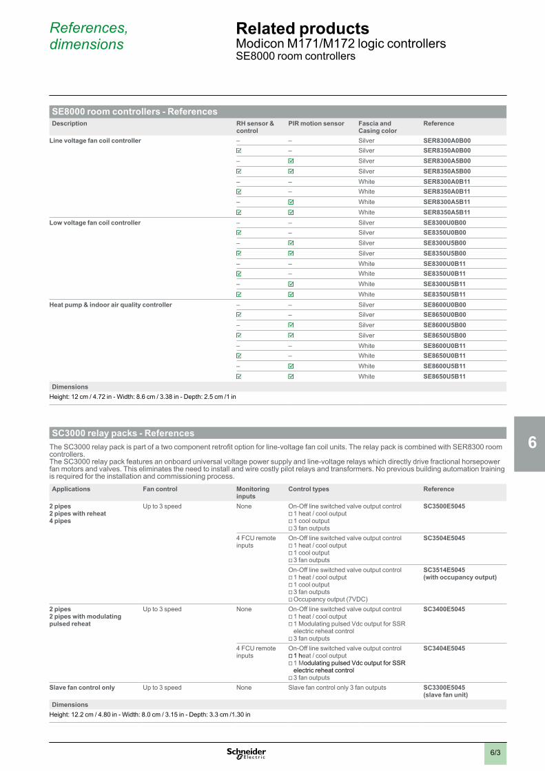
2
1
3
4
5
6
7
8
9
10
2
1
3
4
5
6
7
8
9
10
6/36/3
References, dimensions
Related productsModicon M171/M172 logic controllersSE8000 room controllers
SE8000 room controllers - ReferencesDescription RH sensor &
control PIR motion sensor Fascia and
Casing colorReference
Line voltage fan coil controller – – Silver SER8300A0B00 – Silver SER8350A0B00
– Silver SER8300A5B00 Silver SER8350A5B00
– – White SER8300A0B11 – White SER8350A0B11
– White SER8300A5B11 White SER8350A5B11
Low voltage fan coil controller – – Silver SE8300U0B00– Silver SE8350U0B00
– Silver SE8300U5B00Silver SE8350U5B00
– – White SE8300U0B11– White SE8350U0B11
– White SE8300U5B11White SE8350U5B11
Heat pump & indoor air quality controller – – Silver SE8600U0B00– Silver SE8650U0B00
– Silver SE8600U5B00Silver SE8650U5B00
– – White SE8600U0B11– White SE8650U0B11
– White SE8600U5B11White SE8650U5B11
DimensionsHeight: 12 cm / 4.72 in - Width: 8.6 cm / 3.38 in - Depth: 2.5 cm /1 in
SC3000 relay packs - ReferencesThe SC3000 relay pack is part of a two component retrofit option for line-voltage fan coil units. The relay pack is combined with SER8300 room controllers.The SC3000 relay pack features an onboard universal voltage power supply and line-voltage relays which directly drive fractional horsepower fan motors and valves. This eliminates the need to install and wire costly pilot relays and transformers. No previous building automation training is required for the installation and commissioning process.
Applications Fan control Monitoring inputs
Control types Reference
2 pipes2 pipes with reheat4 pipes
Up to 3 speed None On-Off line switched valve output control v 1 heat / cool output v 1 cool output v 3 fan outputs
SC3500E5045
4 FCU remote inputs
On-Off line switched valve output control v 1 heat / cool output v 1 cool output v 3 fan outputs
SC3504E5045
On-Off line switched valve output control v 1 heat / cool output v 1 cool output v 3 fan outputs v Occupancy output (7VDC)
SC3514E5045(with occupancy output)
2 pipes2 pipes with modulating pulsed reheat
Up to 3 speed None On-Off line switched valve output control v 1 heat / cool output v 1 Modulating pulsed Vdc output for SSR electric reheat control v 3 fan outputs
SC3400E5045
4 FCU remote inputs
On-Off line switched valve output control v 1 heat / cool output v 1 Modulating pulsed Vdc output for SSR electric reheat control v 3 fan outputs
SC3404E5045
Slave fan control only Up to 3 speed None Slave fan control only 3 fan outputs SC3300E5045(slave fan unit)
DimensionsHeight: 12.2 cm / 4.80 in - Width: 8.0 cm / 3.15 in - Depth: 3.3 cm /1.30 in

6/56/4
8.0
Selection guide Related productsModicon M171/M172 logic controllersOperator dialog terminals: MagelisTM Small panels
Applications Display of graphic pages Display of graphic pages
Type of terminal Small panels with monochrome or color touch screen Small panels with color touch screen
Display Type Monochrome STN LCD (200 x 80 pixels), backlit- Green, orange, and red, or- White, pink, and red
Color TFT LCD (480 x 272 pixels)
Color QVGA TFT LCD (320 x 240 pixels)
Capacity 3.4" (monochrome) 4.3” (color) 3.5" (color) 5.7" (color)
Data entry Via touch screen Via touch screen
Memory capacity Application 16 MB Flash 32 MB Flash 32 MB Flash
Expansion – –
Functions Maximum number of pages Limited by internal FLASH EPROM memory capacity
8999 Limited by internal FLASH EPROM memory capacity
Variables per page Unlimited 384 Unlimited
Representation of variables Alphanumeric, bitmap, bargraph, gauge, curves, buttons, LEDs Alphanumeric, bitmap, bargraph, gauge, curves, buttons, LEDs
Recipes 32 groups of 64 recipes max Ingredients 8192 32 groups of 64 recipes
Curves Yes, with log Yes, with log
Alarm logs Yes Yes
Real-time clock Access to the PLC real-time clock Option: RTC battery set Access to the PLC real-time clock
Alarm relay – –
Buzzer Yes Yes
Communication Asynchronous serial link RS 232C/RS 485 (1)RS 232C using Zelio protocol (2)
RS 232C/RS 485 (1)RS 232C (2)
RS 232C/RS 485
Downloadable protocols Uni-TE, Modbus and for PLC brands: Allen-Bradley, Omron, Mitsubishi, Siemens Uni-TE, Modbus and for PLC brands: Allen-Bradley, Omron, Mitsubishi, Siemens
Printer link USB for serial or parallel printer – USB for serial or parallel printer
USB ports 1 host type A and 1 device type mini-B 1 host type A and 1 device type mini-B
Networks 1 Ethernet TCP/IP port (10BASE-T/100BASE-TX) (3) 1 Ethernet TCP/IP port (10BASE-T/100BASE-TX)
Development software Vijeo Designer (on Windows XP Professional and Windows 7 Business 32-bit and 64-bit)
Vijeo XD (on Windows 7 and Windows 8) Vijeo Designer (on Windows XP Professional and Windows 7 Business 32-bit and 64-bit)
Operating system Magelis Magelis
References HMISTO5pp HMISTO7p5 ( ) HMISTU655 HMISTU655W
HMISTU855 HMISTU855W
(1) Only HMISTO511, HMISTO512, HMISTO715(2) Only HMISTO501, HMISTO705(3) Only HMISTO531, HMISTO532, HMISTO735
Available 1st quarter 2016
2
1
3
4
5
2
1
3
4
5
6
7
8
9
10
2
1
3
4
5
6
7
8
9
10
6
7
8
9
10
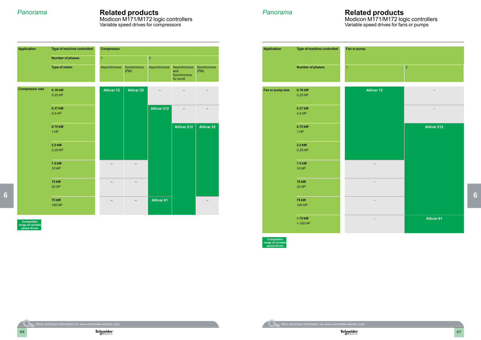
Application Type of machine controlled Compressor
Number of phases 1 3
Type of motor Asynchronous Synchronous (PM)
Asynchronous Asynchronous and Synchronous for scroll
Synchronous (PM)
Compressor size 0.18 kW0.25 HP
Altivar 12 Altivar 32 – – –
0.37 kW0.5 HP
Altivar 312 – –
0.75 kW1 HP
Altivar 212 Altivar 32
2.2 kW0.25 HP
7.5 kW10 HP
– –
15 kW20 HP
– –
75 kW100 HP
– – Altivar 61 –
Compatible range of variable
speed drives
Application Type of machine controlled Fan or pump
Number of phases 1 3
Fan or pump size 0.18 kW0.25 HP
Altivar 12 –
0.37 kW0.5 HP
–
0.75 kW1 HP
Altivar 212
2.2 kW0.25 HP
7.5 kW10 HP
–
15 kW20 HP
–
75 kW100 HP
–
> 75 kW> 100 HP
– Altivar 61
Compatible range of variable
speed drives
Panorama Related productsModicon M171/M172 logic controllersVariable speed drives for fans or pumps
Related productsModicon M171/M172 logic controllersVariable speed drives for compressors
Panorama
6/76/6
2
1
3
4
5
6
7
8
9
10
2
1
3
4
5
2
1
3
4
5
2
1
3
4
5
6
7
8
9
10
6
7
8
9
10
6
7
8
9
10
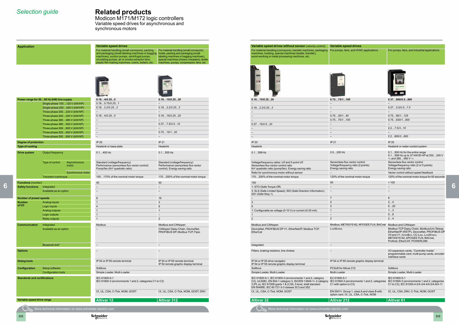
Application Variable speed drives Variable speed drives without sensor (velocity control) Variable speed drivesFor material handling (small conveyors), packing and packaging (small labeling machines or bagging machines), suction pumps, centrifugal pumps, circulating pumps, air or smoke extractor fans, plastic film making machines, ovens, boilers, etc.
For material handling (small conveyors), hoists, packing and packaging (small labeling machines or bagging machines), special machines (mixers, kneaders), textile machines, pumps, compressors, fans, etc.
For material handling (conveyors), transfer machines, packaging machines, hoisting, special machines (textile, transfer), wood-working or metal processing machines, etc.
For pumps, fans, and HVAC applications For pumps, fans, and industrial applications
Power range for 50…60 Hz (kW) line supply 0.18…4/0.25...5 0.18…15/0.25...20 0.18…15/0.25...20 0.75…75/1...100 0.37…800/0.5...900Single-phase 100…120 V (kW/HP) 0.18…0.75/0.25...1 – – – –Single-phase 200…240 V (kW/HP) 0.18…2.2/0.25...3 0.18…2.2/0.25...3 0.18…2.2/0.25...3 – 0.37…5.5/0.5...7.5Three-phase 200…230 V (kW/HP) – – – – –Three-phase 200…240 V (kW/HP) 0.18…4/0.25...5 0.18…15/0.25...20 – 0.75…30/1...40 0.75…90/1...125Three-phase 380…480 V (kW/HP) – – – 0.75…75/1...100 0.75…630/1...900Three-phase 380…500 V (kW/HP) – 0.37…7.5/0.5...10 0.37…15/0.5...20 – –Three-phase 500…600 V (kW/HP) – – – – 2.2…7.5/3...10Three-phase 525…600 V (kW/HP) – 0.75…15/1...20 – – –Three-phase 500…690 V (kW/HP) – – – – 2.2…800/3...800
Degree of protection IP 20 IP 21 IP 20 IP 21 IP 20Type of cooling Heatsink or base plate Heatsink Heatsink Heatsink or water-cooled system
Drive system Output frequency 0.1…400 Hz 0.1…500 Hz 0.1…599 Hz 0.5…200 Hz 0.1…500 Hz for the entire range 0.1…599 Hz up to 37 kW/50 HP at 200…240 V a and 380…480 V a
Type of control Asynchronous motor
Standard (voltage/frequency)Performance (sensorless flux vector control)Pump/fan (Kn2 quadratic ratio)
Standard (voltage/frequency)Performance (sensorless flux vector control). Energy saving ratio
Voltage/frequency ratios: U/f and 5-point U/fSensorless flux vector control ratioKn2 quadratic ratio (pump/fan). Energy saving ratio
Sensorless flux vector controlVoltage/frequency ratio (2 points)Energy saving ratio
Sensorless flux vector controlVoltage/frequency ratio (2 or 5 points) Energy saving ratio
Synchronous motor – Ratio for synchronous motor without sensor – Vector control without speed feedbackTransient overtorque 150…170% of the nominal motor torque 170…200% of the nominal motor torque 170…200% of the nominal motor torque 120% of the nominal motor torque 120% of the nominal motor torque for 60 seconds
Functions (number) 40 50 150 50 > 100Safety functions Integrated – – 1: STO (Safe Torque Off) – –
Available as an option – – 3: SLS (Safe Limited Speed), SDI (Safe Direction Information), SS1 (Safe Stop 1)
– –
Number of preset speeds 8 16 – 7 8Number of I/O
Analog inputs 1 3 3 2 2…4Logic inputs 4 6 6 3 6…20Analog outputs 1 1 1: Configurable as voltage (0-10 V) or current (0-20 mA) 1 1…3Logic outputs 1 – 1 – 0…8Relay outputs 1 2 2 2 2…4
Communication Integrated Modbus Modbus and CANopen Modbus and CANopen Modbus, METASYS N2, APOGEE FLN, BACnet Modbus and CANopenAvailable as an option – CANopen Daisy Chain, DeviceNet,
PROFIBUS DP, Modbus TCP, FipioDeviceNet, PROFIBUS DP V1, EtherNet/IP, Modbus TCP, EtherCat
LonWorks Modbus TCP Daisy Chain, Modbus/Uni-Telway, EtherNet/IP (RSTP), DeviceNet, PROFIBUS DP V0 and V1, InterBus, CC-LInk, LonWorks, METASYS N2, APOGEE FLN, BACnet, Profinet, EtherCAT, POWERLINK
Bluetooth link® – – Integrated –
Options – – Filters, braking resistors, line chokes – I/O expansion cards, “Controller Inside” programmable card, multi-pump cards, encoder interface cards
Dialog tools IP 54 or IP 65 remote terminal IP 54 or IP 65 remote terminalIP 54 remote graphic display terminal
IP 54 or IP 55 drive navigatorIP 54 or IP 55 remote graphic display terminal
IP 54 or IP 65 remote graphic display terminal
Configuration Setup software SoMove SoMove PCSoft for Altivar 212 SoMoveConfiguration tools Simple Loader, Multi-Loader Simple Loader, Multi-Loader Multi-Loader Simple Loader, Multi-Loader
Standards and certifications IEC 61800-5-1 IEC 61800-3 (environments 1 and 2, categories C1 to C3)
IEC 61800-5-1, IEC 61800-3 (environments 1 and 2, category C2), UL508C, EN 954-1 category 3, ISO/EN 13849-1/- 2 category 3 (PL e), IEC 61508 (parts 1 & 2) SIL 3 level, draft standard EN 50495E, IEC 60 721-3-3 classes 3C3 and 3S2
EC 61800-5-1 IEC 61800-3 (environments 1 and 2, categories C1 with option to C3)
IEC 61800-5-1 IEC 61800-3 (environments 1 and 2, categories C1 to C3), IEC 61000-4-2/4-3/4-4/4-5/4-6/4-11
e, UL, CSA, C-Tick, NOM, GOST e, UL, CSA, C-Tick, NOM, GOST, DNV e, UL, CSA, C-Tick, NOM, GOST EN 55011: Group 1, class A and class B with option card. e, UL, CSA, C-Tick, NOM
e, UL, CSA, DNV, C-Tick, NOM, GOST
Variable speed drive range Altivar 12 Altivar 312 Altivar 32 Altivar 212 Altivar 61
Selection guide Related productsModicon M171/M172 logic controllersVariable speed drives for asynchronous and synchronous motors
6/96/8
2
1
3
4
5
2
1
3
4
5
2
1
3
4
5
6
7
8
9
10
6
7
8
9
10
6
7
8
9
10
6
7
8
9
10
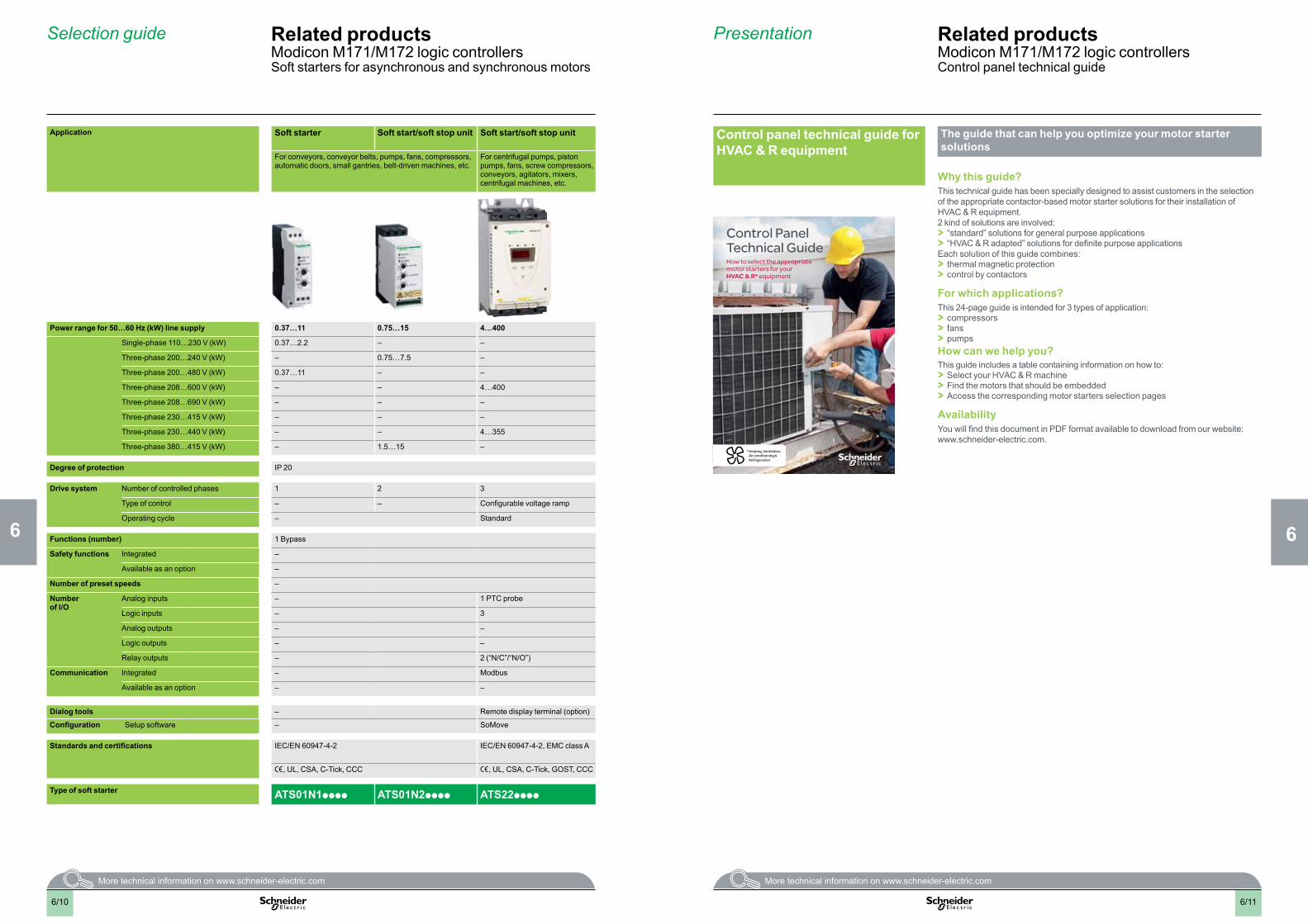
Application Soft starter Soft start/soft stop unit Soft start/soft stop unit
For conveyors, conveyor belts, pumps, fans, compressors, automatic doors, small gantries, belt-driven machines, etc.
For centrifugal pumps, piston pumps, fans, screw compressors, conveyors, agitators, mixers, centrifugal machines, etc.
Power range for 50…60 Hz (kW) line supply 0.37…11 0.75…15 4…400
Single-phase 110…230 V (kW) 0.37…2.2 – –
Three-phase 200…240 V (kW) – 0.75…7.5 –
Three-phase 200…480 V (kW) 0.37…11 – –
Three-phase 208…600 V (kW) – – 4…400
Three-phase 208…690 V (kW) – – –
Three-phase 230…415 V (kW) – – –
Three-phase 230…440 V (kW) – – 4…355
Three-phase 380…415 V (kW) – 1.5…15 –
Degree of protection IP 20
Drive system Number of controlled phases 1 2 3
Type of control – – Configurable voltage ramp
Operating cycle – Standard
Functions (number) 1 Bypass
Safety functions Integrated –
Available as an option –
Number of preset speeds –
Number of I/O
Analog inputs – 1 PTC probe
Logic inputs – 3
Analog outputs – –
Logic outputs – –
Relay outputs – 2 (“N/C”/“N/O”)
Communication Integrated – Modbus
Available as an option – –
Dialog tools – Remote display terminal (option)
Configuration Setup software – SoMove
Standards and certifications IEC/EN 60947-4-2 IEC/EN 60947-4-2, EMC class A
e, UL, CSA, C-Tick, CCC e, UL, CSA, C-Tick, GOST, CCC
Type of soft starter ATS01N1pppp ATS01N2pppp ATS22pppp
Selection guide Related productsModicon M171/M172 logic controllersSoft starters for asynchronous and synchronous motors
Presentation Related productsModicon M171/M172 logic controllersControl panel technical guide
Control panel technical guide for HVAC & R equipment
The guide that can help you optimize your motor starter solutions
Why this guide?This technical guide has been specially designed to assist customers in the selection of the appropriate contactor-based motor starter solutions for their installation of HVAC & R equipment.2 kind of solutions are involved: > “standard” solutions for general purpose applications > “HVAC & R adapted” solutions for definite purpose applications
Each solution of this guide combines: > thermal magnetic protection > control by contactors
For which applications?This 24-page guide is intended for 3 types of application: > compressors > fans > pumps
How can we help you?This guide includes a table containing information on how to: > Select your HVAC & R machine > Find the motors that should be embedded > Access the corresponding motor starters selection pages
AvailabilityYou will find this document in PDF format available to download from our website:www.schneider-electric.com.
Control Panel Technical GuideHow to select the appropriate motor starters for your HVAC & R* equipment
* Heating, Ventilation, Air conditioning & Refrigeration
6/116/10
666
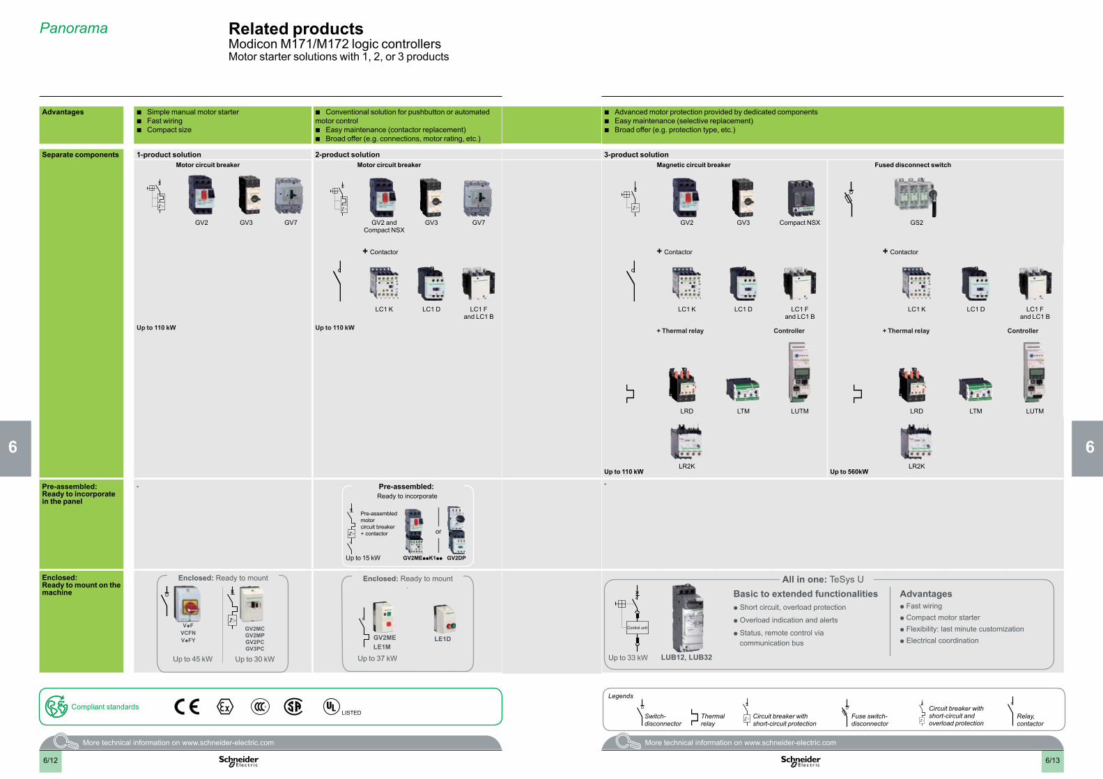
Advantages b Simple manual motor starter b Fast wiring b Compact size
b Conventional solution for pushbutton or automated motor control
b Easy maintenance (contactor replacement) b Broad offer (e.g. connections, motor rating, etc.)
b Advanced motor protection provided by dedicated components b Easy maintenance (selective replacement) b Broad offer (e.g. protection type, etc.)
Separate components 1-product solution 2-product solution 3-product solutionMotor circuit breaker Motor circuit breaker Magnetic circuit breaker Fused disconnect switch
GV2 GV3 GV7 GV2 and Compact NSX
GV3 GV7 GV2 GV3 Compact NSX GS2
+ Contactor + Contactor + Contactor
LC1 K LC1 D LC1 F and LC1 B
LC1 K LC1 D LC1 F and LC1 B
LC1 K LC1 D LC1 F and LC1 B
Up to 110 kW Up to 110 kW + Thermal relay Controller + Thermal relay Controller
LRD LTM LUTM LRD LTM LUTM
LR2K LR2KUp to 110 kW Up to 560kW
Pre-assembled: Ready to incorporate in the panel
- Pre-assembled: Ready to incorporate
Up to 15 kW GV2MEppK1pp
or
Pre-assembled motor circuit breaker + contactor
GV2DP
-
Enclosed: Ready to mount on the machine
Enclosed: Ready to mount
Up to 30 kWUp to 45 kW
GV2MC GV2MP GV2PC GV3PC
VpF VCFN VpFY
Enclosed: Ready to mount
Up to 37 kW
LE1DGV2ME LE1M
Up to 33 kW
Control unit
Basic to extended functionalities p Short circuit, overload protection
p Overload indication and alerts
p Status, remote control via communication bus
Advantages p Fast wiringp Compact motor starterp Flexibility: last minute customizationp Electrical coordination
All in one: TeSys U
LUB12, LUB32
Panorama Related productsModicon M171/M172 logic controllersMotor starter solutions with 1, 2, or 3 products
Switch-disconnector
Circuit breaker with short-circuit protection
Fuse switch- disconnector
Circuit breaker with short-circuit and overload protection
Thermal relay
Relay, contactor
Legends
Compliant standardsLISTED
6/136/12
2
1
3
4
5
6
7
8
9
10
2
1
3
4
5
6
7
8
9
10
2
1
3
4
5
6
7
8
9
10
2
1
3
4
5
6
7
8
9
10

Panorama Related productsModicon M171/M172 logic controllersShort-circuit and overload protection
Applications DC circuit protection and disconnection: DC power supplies, generators, batteries, etc.
AC circuit protection and disconnection of machines, electrical distribution in buildings
Protection and disconnection of electrical circuits
Protection of operators against electrical shocks in event of direct or indirect contact with live equipment
Protection of operators against electrical shocks in event of direct or indirect contact with live equipment
Protection of operators against electrical shocks in event of direct or indirect contact with live equipment
Protection of sensitive equipment against voltage surges due to lightning, high power switching, etc.
Acti 9 Multi 9 Acti 9 Multi 9 TeSys DF Acti 9 Multi 9 Acti 9 Multi 9
Description Miniature circuit breaker
Miniature circuit breaker
Miniature circuit breaker
Miniature circuit breaker
Fuse holder RCBO (3) RCBO (3) RCCB (4) Surge arrester
Characteristics Voltage 60 V DC/pole 250 V DC/pole 230/400 V AC 500 V AC
690 V AC
230/400 V AC
Number of poles 1 or 2 1, 2, 3, and 4 – 1P+N 2, 3, and 4P
Nominal current (A) 1 to 63 63 to 125 25 32 50 25 6 to 32 25 to 63 –
8 x 32 mm (0.32 x 1.26 in.)
10 x 38 mm (0.39 x 1.5 in.)
14 x 51 mm (0.5 x 2 in.)
22 x 58 mm (0.87 x 2.28 in.)
Breaking capacity (kA) 6 10 20 120 – – – 20
Load type/Tripping curve (1) B, C, D C B, C, D – C class A 30 or 300 mA C class A 30 or 300 mA Type 2
Width 18 mm (0.71 in.)/pole 27 mm (1.07 in.)/pole
– 36 mm (1.42 in.) 27 to 63 mm (1.06 x 2.48 in.)
36 to 72 mm (1.42 x 2.84 in.)
72 to 120 mm (2.84 x 4.72 in.)
Product reference
IEC Acti 9 iC60N Acti 9 C60H-DC Acti 9 iC60N Acti 9 C120N – Acti 9 DPN Vigi Acti 9 Vigi iC60 blocks (2) Acti 9 RCCB ID Quick PRD 20r
IEC/UL Multi 9 C60N Multi 9 C60H-DC Multi 9 C60N – DF8 DF10 DF14 DF22 – – Multi9 GFP –
(1) Tripping curve: B (3 In < Im < 5 In) standard C (5 In < Im < 10 In) inrush current D (10 In < Im < 14 In) electronics or long cable length
6/156/14
2
1
3
4
5
6
7
8
9
10
2
1
3
4
5
6
7
8
9
10
2
1
3
4
5
6
7
8
9
10
2
1
3
4
5
6
7
8
9
10

Panorama Related productsModicon M171/M172 logic controllersIncoming protection and switching
Applications On-load switching of motors, resistive and inductive loads
Control and disconnection of electrical distribution circuits
Protection and switching of motors
Protection in industrial and tertiary applications
Feeder protection and circuit disconnection for multistandard motor circuit design
Power circuit protection and disconnection in industrial, infrastructure, and building applications
TeSys Vario Compact TeSys GS NG Powerpact Compact
Description Switch disconnectorsRotary switch with fully visible breaking
Switch disconnectors Fuse switch disconnector Circuit breakers Molded case circuit breakers with optional embedded communication and metering possibilities
Isolation and disconnection
Protection –
Characteristics Rated operational current (A)
12 to 175 40 to 2,500 32 to 1,250 10 to 125 15 to 600 16 to 3,200
Number of poles 3 to 6 3 and 4 3 and 4
Short-circuit making capacity at 400 V Icm (kA)
0.5 to 3 50 to 220 5 to 90 10 to 50 18 to 65 25 to 150
Product name V INS GS NG125 NH, NJ, NL NSX/NS
Embedded metering – – – – Micrologic metering adapters
Standards and certifications IEC 60947-3UL508
IEC 60947-3UL508
IEC 60947-3 IEC 60947-2 IEC 60947-2UL508
IEC 60947-2
6/176/16
2
1
3
4
5
6
7
8
9
10
2
1
3
4
5
6
7
8
9
10
2
1
3
4
5
6
7
8
9
10
2
1
3
4
5
6
7
8
9
10

Related productsModicon M171/M172 logic controllersRegulated switch mode power supplies and function modulesPhaseo power supplies
Selection guide
Power suppliesFunction modules
Regulated switch modeFunction modules (Only compatible with Phaseo ABL8RP/ABL8WP power supplies)
ABL8MEM, ABL7RM: 7 to 60 W - Mounting on railABL8REM, ABL7RP: 60 to 144 W - Mounting on rail
ABL8RPS/8RPM/8WPS: 72 to 960 W - Wide input voltage rangeMounting on rail
ABL8DCC: converter modules c 24 V/c 5-12 V
ABL8B: solutions to microbreaks and power outages
ABL8RED24400 : redundancy solution
ABL8PRP24100: solution for discriminating protection of the application
Input voltage 100...240 V a 120...250 V c
100...120 V a and 200...500 V a (1)
380...500 V a 24 V c 24 V c 24 V c 24 V c
Connection to world-wide line supplies
United States- 120 V (in phase-to-neutral)- 240 V (in phase-to-phase)
Single-phase (N-L1) or 2-phase (L1-L2) connection Single-phase (N-L1) or 2-phase (L1-L2) connection
– – – – –
Europe- 230 V (in phase-to-neutral)- 400 V (in phase-to-phase)
Single-phase (N-L1) connection 3-phase (L1-L2-L3) connection
– – – –
United States- 277 V (in phase-to-neutral)- 480 V (in phase-to-phase)
– 3-phase (L1-L2-L3) connection
– – – –
IEC/EN 61000-3-2 conformity Yes for ABL7RP, not for ABL8REM and not applicable for ABL8MEM and ABL7RM Yes – – – –Protection against undervoltage Yes Yes – – – –Protection against overloads and short-circuits Yes, voltage detection. Automatic restart on elimination on the fault Yes, current limitation or undervoltage
detectionYes, current limitation – – –
Diagnostic relay – Yes, depending on model Yes Yes –Compatibility with function modules – Yes with buffer module, battery and battery control modules, redundancy module and
discriminating downstream protection module– – –
with power supplies – – ABL8RP/8WP ABL8RP/8WP ABL8RP/8WP ABL8RP/8WPPower reserve (Boost) 1,25 to 1,4 In during 1 minute, depending on model (with ABL8MEM) No 1,5 In during 4 secondes No – – –
Output voltage 5 V c 12 V c 24 V c 48 V c 24 V c 5 V c 7...12 V c 24 V c 24 V c 24 V c Output current 0.3 A ABL8MEM24003
0.6 A ABL8MEM24006
1.2 A ABL8MEM24012
2 A ABL8MEM12020 ABL8DCC12020
2.5 A ABL7RM24025 ABL7RP4803
3 A ABL8REM24030 ABL8RPS24030
4 A ABL8MEM05040
5 A ABL7RP1205 ABL8REM24050 ABL8RPS24050
6 A ABL8DCC05060
10 A ABL8RPS24100 ABL8PRP24100
20 A ABL8RPM24200 ABL8WPS24200 ABL8BBU24200 ABL8RED24400
40 A ABL8WPS24400 ABL8BUF24400ABL8BBU24400
2x ABL8RED24400
More information Please consult our catalogue “Phaseo, Power supplies & Transformers”, n° DIA3ED2131105EN Please consult our catalogue “Phaseo, Power supplies & Transformers”, n° DIA3ED2131105EN
(1) Except ABL8RPM24200. a 100...120 V and a 200...240 V.
6/196/18
2
1
3
4
5
6
7
8
9
10
2
1
3
4
5
6
7
8
9
10
2
1
3
4
5
6
7
8
9
10
2
1
3
4
5
6
7
8
9
10
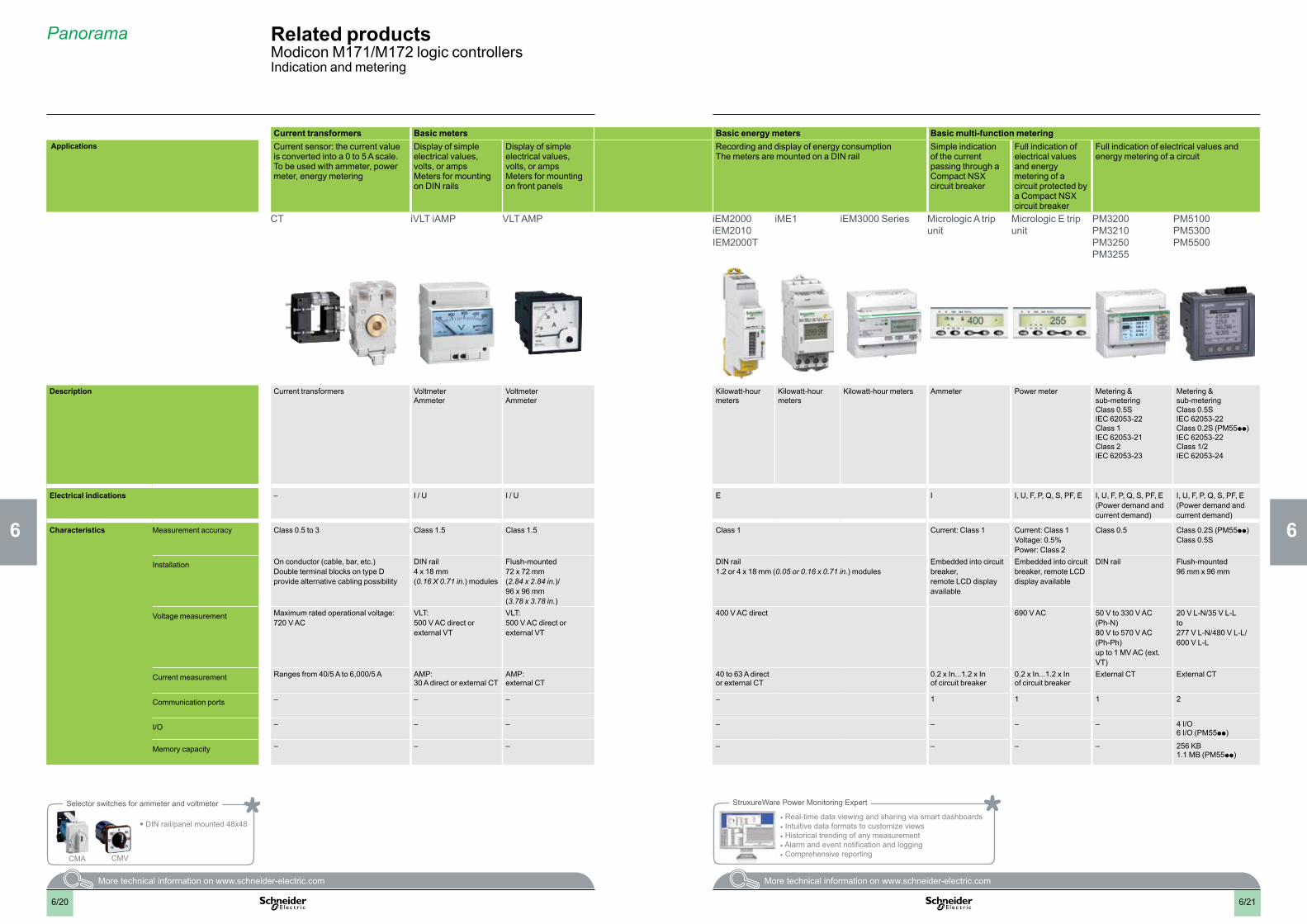
Panorama Related productsModicon M171/M172 logic controllersIndication and metering
Current transformers Basic meters Basic energy meters Basic multi-function metering Applications Current sensor: the current value
is converted into a 0 to 5 A scale.To be used with ammeter, power meter, energy metering
Display of simple electrical values, volts, or ampsMeters for mounting on DIN rails
Display of simple electrical values, volts, or amps Meters for mounting on front panels
Recording and display of energy consumptionThe meters are mounted on a DIN rail
Simple indication of the current passing through a Compact NSX circuit breaker
Full indication of electrical values and energy metering of a circuit protected by a Compact NSX circuit breaker
Full indication of electrical values and energy metering of a circuit
CT iVLT iAMP VLT AMP iEM2000iEM2010IEM2000T
iME1 iEM3000 Series Micrologic A trip unit
Micrologic E trip unit
PM3200PM3210PM3250PM3255
PM5100 PM5300PM5500
Description Current transformers VoltmeterAmmeter
VoltmeterAmmeter
Kilowatt-hour meters
Kilowatt-hour meters
Kilowatt-hour meters Ammeter Power meter Metering & sub-meteringClass 0.5SIEC 62053-22Class 1IEC 62053-21Class 2IEC 62053-23
Metering & sub-meteringClass 0.5SIEC 62053-22Class 0.2S (PM55pp)IEC 62053-22Class 1/2IEC 62053-24
Electrical indications – I / U I / U E I I, U, F, P, Q, S, PF, E I, U, F, P, Q, S, PF, E(Power demand and current demand)
I, U, F, P, Q, S, PF, E(Power demand andcurrent demand)
Characteristics Measurement accuracy Class 0.5 to 3 Class 1.5 Class 1.5 Class 1 Current: Class 1 Current: Class 1Voltage: 0.5% Power: Class 2
Class 0.5 Class 0.2S (PM55pp)Class 0.5S
Installation On conductor (cable, bar, etc.)Double terminal blocks on type D provide alternative cabling possibility
DIN rail 4 x 18 mm (0.16 X 0.71 in.) modules
Flush-mounted 72 x 72 mm (2.84 x 2.84 in.)/ 96 x 96 mm (3.78 x 3.78 in.)
DIN rail1.2 or 4 x 18 mm (0.05 or 0.16 x 0.71 in.) modules
Embedded into circuit breaker,remote LCD display available
Embedded into circuit breaker, remote LCD display available
DIN rail Flush-mounted96 mm x 96 mm
Voltage measurement Maximum rated operational voltage: 720 V AC
VLT: 500 V AC direct or external VT
VLT: 500 V AC direct or external VT
400 V AC direct 690 V AC 50 V to 330 V AC (Ph-N)80 V to 570 V AC (Ph-Ph)up to 1 MV AC (ext. VT)
20 V L-N/35 V L-L to 277 V L-N/480 V L-L/600 V L-L
Current measurement Ranges from 40/5 A to 6,000/5 A AMP: 30 A direct or external CT
AMP: external CT
40 to 63 A director external CT
0.2 x In...1.2 x In of circuit breaker
0.2 x In...1.2 x In of circuit breaker
External CT External CT
Communication ports – – – – 1 1 1 2
I/O – – – – – – – 4 I/O6 I/O (PM55pp)
Memory capacity – – – – – – – 256 KB1.1 MB (PM55pp)
Selector switches for ammeter and voltmeter
• DIN rail/panel mounted 48x48
CMA CMV
StruxureWare Power Monitoring Expert
• Real-time data viewing and sharing via smart dashboards• Intuitive data formats to customize views• Historical trending of any measurement• Alarm and event notification and logging• Comprehensive reporting
6/216/20
2
1
3
4
5
6
7
8
9
10
2
1
3
4
5
6
7
8
9
10
2
1
3
4
5
6
7
8
9
10
2
1
3
4
5
6
7
8
9
10
Chapter 7Product reference index
b Technical data relating to products listed in this chapter is available online at www.schneider-electric.com
2
3
4
7
8
9
10
7/1
b Product reference index
v Index ........................................................................................................ page 7/2
Contents Modicon M171/M172 logic controllers for HVAC and Pumping solutions
7/1
7/2
Index Product reference indexModicon M171/M172 logic controllers for HVAC and Pumping solutions
TM171APBUS 3/235/3
TM171ARS232 3/235/3
TM171ARS485 3/235/3
TM171ASCTB14 3/21
TM171ASCTB27 3/173/21
TM171ASCTBVEV 3/25
TM171DGRP 3/173/19
TM171DLCD2U 3/14
TM171DLED 3/14
TM171DWAL2L 3/14
TM171DWAL2U 3/14
TM171EO14R 3/21
TM171EO15R 3/21
TM171EO22R 3/21
TM171EP14R 3/21
TM171EP27R 3/21
TM171OB22R 3/13
TM171OBM14R 3/13
TM171OBM22R 3/13
TM171OD14R 3/13
TM171OD22R 3/13
TM171ODM14R 3/13
TM171ODM22R 3/13
TM171ODM22S 3/13
TM171OF22R 3/13
TM171OFM22R 3/13
TM171PBM27R 3/17
TM171PDM27R 3/17
TM171PDM27S 3/17
TM171PFE03 3/17
TM171PFE03HR 3/17
TM171SW 4/3
TM171VEVA2 3/25
TM171VEVD4 3/25
TM171VEVM4 3/25
TM172AP12PM 3/19
TM172ASCTB28 3/19
TM172ASCTB42 3/19
TM172PBG28R 3/19
TM172PBG42R 3/19
TM172PDG28R 3/19
TM172PDG28S 3/19
TM172PDG42R 3/19
TM172PDG42S 3/19
TSXCUSB485 4/3
V
VW3A8306D30 4/3
TCSEGWB13FA0 5/5
TCSEK3MDS 5/4
TCSESU033FN0 5/4
TCSESU043F1N0 5/4
TCSESU053FN0 5/4
TCSXCNAMUM3P 4/3
TM1SH284 3/26
TM1SH304 3/26
TM1SH314 3/26
TM1STNTCRN52015 3/26
TM1STNTCRN52030 3/26
TM1STNTCRN52050 3/26
TM1STNTCRN61515 3/26
TM1STNTCRN61530 3/26
TM1STNTCRN61550 3/26
TM1STNTCSF44015 3/26
TM1STNTCSF44030 3/26
TM1STNTCSN62015 3/26
TM1STNTCSN62030 3/26
TM1STNTCSN62050 3/26
TM1STNTCTN62015 3/26
TM1STNTCTN62030 3/26
TM1STNTCWN65605 3/26
TM1STNTCWN75750 3/26
TM1STPTTSN52015 3/26
TM1STPTTSN52030 3/26
TM1STPTTSN52050 3/26
TM1STPTTSN62015 3/26
TM1STPTTSN62030 3/26
TM171ABKPB 3/17
TM171ABKPG 3/17
TM171ACAN 3/235/3
TM171ACB4OAO1M 3/153/21
TM171ACB4OAO2M 3/153/21
TM171ACB4OI1M 3/153/21
TM171ACB4OI2M 3/153/21
TM171ACB4OLAN 3/153/21
TM171ACB4ORS485 3/15
TM171ADMI 4/3
TM171AETH 3/235/3
TM171AETHRS485 3/235/3
TM171ALON 3/235/3
TM171AMB 3/235/3
TM171AMFK 4/3
4
490NTW00002 4/35/4
490NTW00002U 5/4
490NTW00005 5/4
490NTW00005U 5/4
490NTW00012 5/4
490NTW00012U 5/4
490NTW00040 5/4
490NTW00040U 5/4
490NTW00080 5/4
490NTW00080U 5/4
A
ABL7RM24025 6/18
ABL7RP1205 6/18
ABL7RP4803 6/18
ABL8BBU24200 6/18
ABL8BBU24400 6/18
ABL8BUF24400 6/18
ABL8DCC05060 6/18
ABL8DCC12020 6/18
ABL8MEM05040 6/18
ABL8MEM12020 6/18
ABL8MEM24003 6/18
ABL8MEM24006 6/18
ABL8MEM24012 6/18
ABL8PRP24100 6/18
ABL8RED24400 6/18
ABL8REM24030 6/18
ABL8REM24050 6/18
ABL8RPM24200 6/18
ABL8RPS24030 6/18
ABL8RPS24050 6/18
ABL8RPS24100 6/18
ABL8WPS24200 6/18
ABL8WPS24400 6/18
B
BMXXCAUSBH018 4/3
T
TCSECE3M3M1S4 5/4
TCSECE3M3M2S4 5/4
TCSECE3M3M3S4 5/4
TCSECE3M3M5S4 5/4
TCSECE3M3M10S4 5/4
TCSECN300R2 5/4
TCSECU3M3M1S4 5/4
TCSECU3M3M2S4 5/4
TCSECU3M3M3S4 5/4
TCSECU3M3M5S4 5/4
TCSECU3M3M10S4 5/4
2
1
3
4
5
6
7
8
9
10
2
1
3
4
5
6
7
8
9
10


The information provided in this documentation contains general descriptions and/or technical characteristics of the performance of the products contained herein. This documentation is not intended as a substitute for and is not to be used for determining suitability or reliability of these products for specific user applications. It is the duty of any such user or integrator to perform the appropriate and complete risk analysis, evaluation and testing of the products with respect to the relevant specific application or use thereof. Neither Schneider Electric nor any of its affiliates or subsidiaries shall be responsible or liable for misuse of the information contained herein.
Design: Schneider ElectricPhotos: Schneider Electric
October 2015 - V2.0
DIA
3ED
2140
905E
N
www.schneider-electric.com/pumpingwww.schneider-electric.com/hvacmachines
Head Office35, rue Joseph MonierF-92500 Rueil-MalmaisonFrance
Schneider Electric Industries SAS
www.schneider-electric.com/msx
Related Documents