www.moeller.net – Modern Switching Installations Efficiently Fitted, and Wired Securely Technical Essay Dipl.-Ing. Wolfgang Esser The complete range of contac tors, efficient motor- starters and variable speed drives for the motor circuit. New simple to install solutions based on clever communication. Contactors DIL Motor-protective circuit-breakers PKZ Motor-starters MSC Softstarters DS/DM Frequency inverters DF/DV Rapid Link

Welcome message from author
This document is posted to help you gain knowledge. Please leave a comment to let me know what you think about it! Share it to your friends and learn new things together.
Transcript

www.moeller.net
–
Modern Switching Installations
Efficiently Fitted, and Wired Securely
Technical EssayDipl.-Ing. Wolfgang Esser
The complete range ofcontac tors, efficient motor-starters and variable speeddrives for the motor circuit.New simple to install solutions based on clevercommunication.
Contactors DIL
Motor-protectivecircuit-breakers PKZ
Motor-starters MSC
Softstarters DS/DM
Frequency invertersDF/DV
Rapid Link
VER1200_2100-938.indd 1VER1200_2100-938.indd 1 29.10.2008 13:34:52 Uhr29.10.2008 13:34:52 Uhr
2
Overview of Contentsand Preface
Page
Contents and preface Overview 2
xStart – modern switching installations 2efficently fitted, and wired securely –
Excerpt from the system 3
Summary for readers in a hurry Brief description 4
Differentiation between switching installations Switching installation types 5
Volume applications in the lower rating range Distribution of motor ratings 6
xStart – the 45 mm engineering dimension continues to advance – Width standardisation expanded 6
xStart – a contribution towards interface optimisation Compatibility with electronics 8
xStart – connection made to measure Termination technology 8
Rationalisation potential in power distribution Evolutionary stages of 8for relatively large groups of operating media power distribution
Busbar systems – efficient power distribution Busbar systems – 9 with added value in centralised switching installations – busbar adapters
Changes in systems building brought about by Advantages of decentralisation 10the trend towards decentralisation
Three-phase commoning links and mounting rail adapters – efficient Three-phase commoning links, 10power distribution for relatively small groups of switching devices mounting rail adapters
Rapid Link – the decentralised switching installation – System Rapid Link 12
Systematic connection = tool-less plug connection Tool-less plug connection 13
Ready-for-connection starter combinations Reversing and star-delta starters 15
Switching and protecting motors using UL 508 Type F motor-starters Self-Protected 16to North American directives – for worldwide application Combination Motor Controllers
The smallest switching installation – motor-protective circuit-breaker PKZM motor-protective 19in a surface mounting enclosure circuit-breakers
Handy motor-starter selection aid The selection slide 20
Validity Status of development 21 and of the Standards
The type-tested system of switching installations specifically for the panel builder 22
Literature Further information 23
–Modern Switching Installations Efficiently Fitted, and Wired SecurelyAt the Hannover Fair 2004, and also at the Light & Building exhibition in Frankfurt, Moeller presented its new motor-starter system, xStart (Figure 1), for rated currents up to 170A [1]. At both these venues, the company also introduced the new switching cabinet system, xEnergy [2, 3].
The two systems optimally complement one another. Switching and protective devices are means to an end. In the final analysis, they are intended for the implementation of power distribution or automation applications for machines
or systems. Switching devices, in the style that is normal for the application in question, must also always be housed in the proper way. Power distribution systems in switching cabinets provide the essential main current connections to the switchgear.
Moeller intends to work even closer together with its system builder partners in the future, in order to hand over to them even more of the implementation tasks. It was logical therefore to make the two product systems compatible and design them in a way that would make their application childs play for existing and new partners alike, by ensuring that all the components could be safely, reliably, quickly and efficiently combined with one another.
This article aims to focus particularly on how the xStart switching and protective devices contribute to rational engineering work.
VER1200_2100-938.indd 2VER1200_2100-938.indd 2 29.10.2008 13:34:55 Uhr29.10.2008 13:34:55 Uhr

3
Range (s)
66
10
Time
1 100
58
65
57
NC
NO
16
26
27
6
18
17
19
2522
24
23
2229
20
21 3433
32
31
35
28
30
15
51
210
8
10
9
6
12
7
3 123
111111
13 14
4
10
14
Contactors
Contactor up to 12 A
Contactor up to 32 A
Suppressor circuit
Motorentstörglied
Side-mounted auxiliary contact
Top-mounted auxiliary contact
Electronic Timer
Contactor up to 65 A
Contactor up to 150 A
Side-mounted auxiliary contact
Top mounted auxiliary contact
Overload Relays
Overload relay up to 32 A
Overload relay up to 65 A
Overload relay up to 150 A
For separate mounting
Motor-Protective Switches
Motor-Protective Switch
with rotary actuation
Motor-Protective Switch
with pushbutton actuation
Current limiter module
Shunt- and undervoltage releases
Trip-indicating auxiliary contact
Side-mounted auxiliary contact
Front auxiliary contact
Early-make auxiliary contact
Door-coupling rotary handle
and extension shaft
Early-make auxiliary contact
Insulated flush mounting enclosure
Insulated surface mounting enclosure
with Emergency-Stop pushbutton
Starter
Electrical link
Mechanical link
Combination plug-in connector
Motorstarter with
combination plug-in technology
Clip plate
Busbar adapter
Top-hat rail adapter
SmartWire module
Figure 1: This diagrammatic representation shows the main components of the xStart product system and how they fit together.
Excerpt from the SystemView without PKZM 4 and contactors up to 150A. For the complete range, see the current Main Catalogue.Auxiliary and main current connections up to 12A, either with screw terminals or spring-loaded terminals.
1
2
3
4
5
6
7
8
9
10
11
12
13
14
15
16
17
18
19
20
21
22
23
24
25
26
27
28
29
30
31
32
33
34
35
VER1200_2100-938.indd 3VER1200_2100-938.indd 3 29.10.2008 13:34:56 Uhr29.10.2008 13:34:56 Uhr

4
Summary for Readers in a Hurry
The article briefly describes various types of switching installation and their specific requirements for switching and protective devices to be fitted. The remainder of the article deals chiefly with the advantages that the new product system, xStart, brings for engineering and device assembly. The components of the xStart system switch and protect operating media up to 170A, in this way covering the current range of equipment for the potentially most numerous applications for power distribution and automation in machine and system building. Beyond this, for the higher current ranges, the fully compatible NZM circuit-breakers and large DIL M contactors are available. These devices were developed in the last three to four years and were equipped with progressive properties that make them suitable for worldmarkets [4 to 6].
In addition to the advantages of the xStart components by reduction in mounting width and in heat dissipation, specific benefits can also be achieved by selecting the optimum power distribu-tion system for the switching installation in question. Depending on the current ratings involved, these can be busbar systems or compact three-phase commoning links. The critical magnitude of the current to be taken into account
in this, may also depend on whether centralised or decentralised switching installations are to be created. Moeller is introducing the fully modular system, Rapid Link, as a particularly advantageous
concept for decentralised systems. Outstanding operational benefits for system building result from the time-savings and error reduction achievedby applying the new tool-less plug connection technology, by using busbar or mounting rail adapters and by the availability of ready-for-connection switchgear combinations. All the components introduced are suitable for use the world over and have the required approvals. The specialrequirements and solutions for motor-starters for the North American market are described, and that the motor-starters designed for the North American market are also suitable for use worldwide. The solutions presented meet the expectations of many machine equipment producers for a switching installation concept comprising aminimum of country-specific variants. All the switchgear presented is housed in the new enclosures from the xEnergy range, which are normal and optimal for the application in question. As an alternative to the Protection Class I enclosures, for systems with protective earth terminal, Moeller can also supply totally insulated enclosures and distribution boards to Protection Class II (Figure 2).
Figure 2: Example of a totally insulated distribution board (Protection Class II), ideal for installation ajacent to operating media in demanding environments.
VER1200_2100-938.indd 4VER1200_2100-938.indd 4 29.10.2008 13:34:57 Uhr29.10.2008 13:34:57 Uhr

5
1 EVU = Electricity supply company2 VNB = Distribution network operator3 TTA = Type-Tested Assemblies4 PTTA = Partially Type-Tested Assemblies
5 MCC = Motor Control Centre6 Inherently short-circuit proof protective switches have internal resistance (bimetals) of such a
magnitude that it protects them from destruction by short-circuit currents (in this case of up to 150kA).
Differentiation between switching installations
There is a great heterogeneity of demands made on switchgear cabinets and their mounting and wiring systems. There are considerable differences depending on the application purpose of a switching installation, its geometrical size, its current rating and the size of devices to be built in. Roughly, one can distinguish between purely power distribution
installations (Figure 3) and electrical equipment for machines and systems, i.e. machine and installation control systems including circuit-breakers and protective devices (Figure 4).Among the power distribution systems to DIN EN 60439-1 [7], there are further structural differences between installations for industrial use:
they sometimes carry higher • operational voltages, higher short-circuit ratings, • higher demands of selectivity• higher accessibility standards for • example by means of withdrawability or using the Arcon arc-fault protection system from Moeller, higher individual ratings of • operating media to be supplied, e.g. motor-starters,
and for use in the equipment of buildings (Figure 5),
with optimisation of modular • installation devices (service distribution boards), a less heavy enclosure construction • for lower current ratings, optimisation of the design for • residential and special purpose buildings,
as well as more focused national • and regional requirements of EVUs1 and VNBs2, additional requirements to • IEC / EN 60 439-3 [8], release for application in locations • where laymen have access to the equipment, for switching or for exchange of fuses.
Power distribution installations are typically engineered in sections with a relatively high level of standardisation facilitating compliance with TTA3 or
PTTA4 requirements (Table 1). Often, even in the industrial power distribution boards, there are motor-starter sections and/or smaller panels containing modular rail-mounted devices mixed in. In the motor-starter sections of power distribution installations, one often finds withdrawable modules with one or two drives being supplied from a single module where the packing density is high (MCC5 distribution boards).
In power distribution installations, but also in the electrical equipment for systems in the raw materials industry, one finds ever higher levels of operational voltages (500V, 690V and sometimes 1000V) and an increase in short-circuit ratings to be controlled to up to 150kA.Such trends are also apparent for the ‘small’ stand-alone power supply on large cargo ships. For such stringent requirements, the xStart system offers motor-protective circuit-breakers that are inherently short-circuit proof6 up to 150kA, for example.
Figure 3: Example of a typical power distribution installation in sections.
Figure 4: Example of a switching installation for the automation of machines and systems, each with a share of the power section and control section.
Figure 5: Example of a power distribution instal-lation for supply to the infrastructure and for the automation of building services.
Type tests for type-tested low-voltage switchgear and controlgear assemblies (TTA), to IEC / EN 60 439-1
Verification of short-circuit withstand strength,
Verification of overtemperature limit,
Verification of protective conductor continuity,
Verification of creepage distances and air clearances,
Verification of dielectric strength,
Verification of mechanical function,
Verification of IP degree of protection,
and other verifications.
Table 1: With the xEnergy system, Moeller offers type-tested switching installations that have successfully passed the above type tests, as well as meeting the building instructions (BA) and installation instructions (AWA) for the further equipment by external system buil-ders. Such system builders then rank as respon-sible manufacturers of switching installations in accordance with IEC/EN 60 439-1[7]. The system builder has to carry out and document routine tests on the completed switching installations.
VER1200_2100-938.indd 5VER1200_2100-938.indd 5 29.10.2008 13:34:58 Uhr29.10.2008 13:34:58 Uhr

6
The efficient NZM circuit-breakers too are designed to withstand such high short-circuits, with a view to future requirements. Increasingly high currents, at present about 2000A to 5000A, must be controlled in wind farms nowadays, and for this application, powerful vacuum contactors with a long electrical service life and open-type IZM circuit-breakers are available.
Switching installations involving more control functions (e.g. machine equipment) are normally engineered to individual requirement. There are often specific, safety-related requirements to IEC / EN 60 204-1 [9], the directive for the electrical equipment of machines, to be taken into account. With such switching installations, particularly when there are volume orders, additional requirements may arise in terms of the rational handling of components. For series-manufactured machines for stock, for which no specific order exists at the time, components must be as universally applicable as possible to as yet unknown user locations with hard to predict characteristics such as:
system type and short-circuit ratings, • unknown reliability of power supply, • regionally customary fuse systems • and problematic logistics for spares, as well as nationally special conditions • and approval requirements.
Differentiation is frequently made nowadays between centralised and decentralised system concepts. Each makes different demands on the enclosures and the concepts differ in terms of current ratings, as well as the operating media to be provided with power (Table 2). In switching installations for power distribution, as well as those for the electrical equipment of machines, networking tasks occur with increasing frequency these days. However, they differ in their requirement in terms of processing speed and of information data content [10, 11]. Networking is an essential prerequisite for implementation of decentralised system concepts.
Volume applications in the lower rating range
Of course, the superlative technical data described are impressive and effective in the market and benefit the image of a manufacturer of switching and protective devices. Moeller covers such spectacular applications very well technically, as well as economically, with its outstanding xStart system, the large DIL contactors, the NZM and IZM circuit-breakers, as well as the high-level switching installations of the MODAN system. The volume business, however, continues to lie in the lower rating range. Figure 6 shows the ratings distribution of three-phase motors produced in Germany, according to production-statistical data issued by the ZVEI7. Worldwide, the distribution is similar. The statistics on which the data are based covers all motors of ≤ 75 kW. 97% of all three-phase motors have a rating of ≤ 15 kW. The tool-less plug technology presented in this article, covers the 7.5 kW rating range. Potentially, more than 80% of all motors can be switched and protected using this new technology.
xStart – the 45 mm engineering dimension continues to advance
The application range of the PKZM 0 motor-protective circuit-breakers, only 45 mm in width, has been expanded by 28 % by the xStart system extending the ratings from 25A to 32A. At the same time, the width of the 15kW contactors was reduced by 25 %, from 60mm to 45mm. This means that, at Moeller, all the protective circuit-breakers and contactors for the volume business up to 15kW are now uniformly only 45mm in width. A critical factor for the success of this very effective grid dimension, was the introduction a few years ago, of the one- or two-contact auxiliary contact modules for front mounting to motor-protective circuit-breakers. In this way, six switches with front mounted auxiliary contacts can be fitted into the mounting width of five motor-protective circuit-breakers with side mounted auxiliary contacts. This represents an improvement by 20%. The auxiliary contacts on contactors have been accommodated in a component width of 45mm for some time, but within the xStart system, the rating range of
Figure 6: The distribution, within the total of three-phase motors produced, allows a sufficiently accurate deduction of the ratings-related distribution of the switching and protective devices involved. More accurate analyses of the distribution among motors are possible via production figures of motor-protective devices that give exact current ratings within a range of 0.75kW to 3kW. The ratio between quantitative potential of large motors and small motors is about 1:1000.
7 ZVEI = Trade association for electrical manufacturers in Germany
Excerpt from the cumulative distribution of three-phase motor sizes According to ZVEI production statistics 2002 and 2003
Total of all LV three-phase motors < 75 kW = 100 %
Motor rating in kW
Cu
mu
lati
ve d
istr
ibu
tio
n in
%
IMD-MS / Esser 07.05.2004
VER1200_2100-938.indd 6VER1200_2100-938.indd 6 29.10.2008 13:35:10 Uhr29.10.2008 13:35:10 Uhr
7
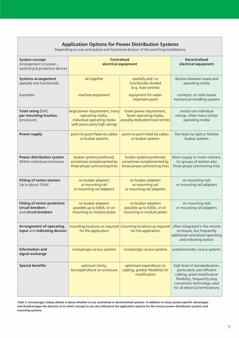
Application Options for Power Distribution SystemsDepending on size and spatial and functional division of the switching installations
System concept Arrangement of power-,switching & protective devices
Centralised electrical equipment
Decentralised electrical equipment
Systems arrangementspatially and functionally
all together spatially and / or functionally divided (e.g. load centres)
division between loads and operating media
Examples: machine equipment equipment for water treatment plant
conveyor- or roller based mechanical handling systems
Total rating [kW]per mounting location(enclosure)
large power requirement, many operating media,
individual operating media with particularly high ratings
lower power requirement,fewer operating media,
possibly dedicated load centres
mostly low individual ratings, often many similar
operating media
Power supply point-to-point feed via cables or busbar systems
point-to-point feed via cables or busbar systems
line feed via rigid or flexible busbar systems
Power distribution systemWithin individual enclosures
busbar systems preferred,sometimes complemented by three-phase commoning links
busbar systems preferred,sometimes complemented by three-phase commoning links
direct supply to motor-starters, for groups of starters also
three-phase commoning links
Fitting of motor-startersUp to about 15kW
on busbar adaptersor mounting rail
or mounting rail adapters
on busbar adaptersor mounting rail
or mounting rail adapters
on mounting railsor mounting rail adapters
Fitting of motor-protective circuit-breakers – and circuit-breakers
on busbar adapterspossible up to 630A, or onmounting or module plates
on busbar adapterspossible up to 630A, or onmounting or module plates
on mounting railsor mounting rail adapters
Arrangement of operating, input and indicating devices
mounting locations as required for the application
mounting locations as required for the application
often integrated in the remote enclosure, but frequently
additional centralised operating and indicating station
Information andsignal exchange
increasingly via bus systems increasingly via bus systems predominantly via bus systems
Special benefits optimum clarity,less expenditure on enclosure
optimised expenditure on cabling, greater flexibility for
modification
high level of standardisation,particularly cost-efficient
cabling, great modification flexibility, frequently plug
connection technology used for all electrical terminations
Table 2: Increasingly, todays debate is about whether to use centralised or decentralised systems. In addition to many system-specific advantages and disadvantages the decision as to which concept to use also influences the application options for the various power distribution systems and mounting systems.
VER1200_2100-938.indd 7VER1200_2100-938.indd 7 29.10.2008 13:35:10 Uhr29.10.2008 13:35:10 Uhr
8
the 45mm contactors with integrated auxiliary contact in the base unit has been expanded to 15kW as well. This engineering dimension is further supported by the fact that the mechanical interlock between two reversing starters now no longer requires additional mounting width. This means yet another width reduction (by 15%) compared to conventional solutions with reversing starter combinations in this rating range. For the busbar adapters and mounting rail adapters described later, the assertion of this engineering dimension means that the number of necessary variants is reduced to 1 or 2 times 45mm, thereby improving the economic aspect of these systems.
The mounting width of contactors with ratings above 38 A was also significantly reduced and matched to the width of protective circuit-breakers. The width saving on contactors up to 72 A is 22%, on contactors up to 170 A it is as much as 25%. The fact that a reduction of heat losses has been achieved at the same time, means that these savings can translate into a higher component packing density.
xStart – a contribution towards interface optimisation
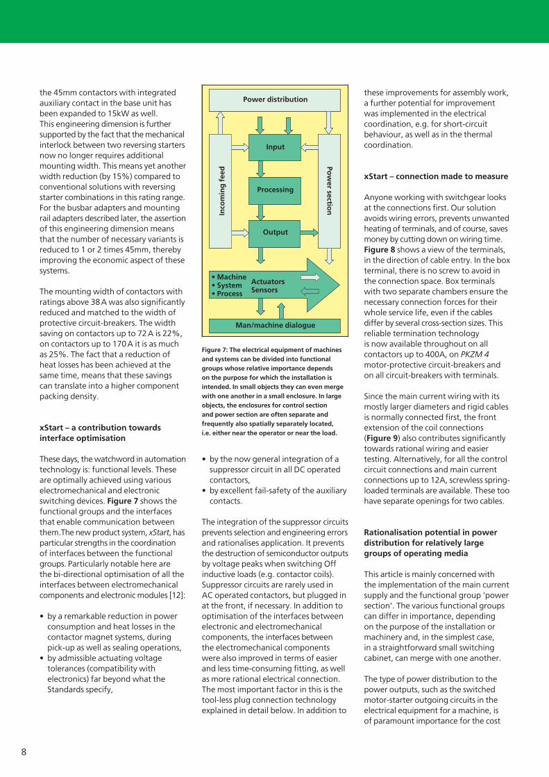
These days, the watchword in automation technology is: functional levels. These are optimally achieved using various electromechanical and electronic switching devices. Figure 7 shows the functional groups and the interfaces that enable communication between them.The new product system, xStart, has particular strengths in the coordination of interfaces between the functional groups. Particularly notable here are the bi-directional optimisation of all the interfaces between electromechanical components and electronic modules [12]:
by a remarkable reduction in power • consumption and heat losses in the contactor magnet systems, during pick-up as well as sealing operations, by admissible actuating voltage • tolerances (compatibility with electronics) far beyond what the Standards specify,
by the now general integration of a • suppressor circuit in all DC operated contactors, by excellent fail-safety of the auxiliary • contacts.
The integration of the suppressor circuits prevents selection and engineering errors and rationalises application. It prevents the destruction of semiconductor outputs by voltage peaks when switching Off inductive loads (e.g. contactor coils). Suppressor circuits are rarely used in AC operated contactors, but plugged in at the front, if necessary. In addition to optimisation of the interfaces between electronic and electromechanical components, the interfaces between the electromechanical components were also improved in terms of easier and less time-consuming fitting, as well as more rational electrical connection. The most important factor in this is the tool-less plug connection technology explained in detail below. In addition to
these improvements for assembly work, a further potential for improvement was implemented in the electrical coordination, e.g. for short-circuit behaviour, as well as in the thermal coordination.
xStart – connection made to measure
Anyone working with switchgear looks at the connections first. Our solution avoids wiring errors, prevents unwanted heating of terminals, and of course, saves money by cutting down on wiring time. Figure 8 shows a view of the terminals, in the direction of cable entry. In the box terminal, there is no screw to avoid in the connection space. Box terminals with two separate chambers ensure the necessary connection forces for their whole service life, even if the cables differ by several cross-section sizes. This reliable termination technology is now available throughout on all contactors up to 400A, on PKZM 4 motor-protective circuit-breakers and on all circuit-breakers with terminals.
Since the main current wiring with its mostly larger diameters and rigid cables is normally connected first, the front extension of the coil connections (Figure 9) also contributes significantly towards rational wiring and easier testing. Alternatively, for all the control circuit connections and main current connections up to 12A, screwless spring-loaded terminals are available. These too have separate openings for two cables.
Rationalisation potential in power distribution for relatively large groups of operating media
This article is mainly concerned with the implementation of the main current supply and the functional group ‘power section’. The various functional groups can differ in importance, depending on the purpose of the installation or machinery and, in the simplest case, in a straightforward small switching cabinet, can merge with one another.
The type of power distribution to the power outputs, such as the switched motor-starter outgoing circuits in the electrical equipment for a machine, is of paramount importance for the cost
Figure 7: The electrical equipment of machines and systems can be divided into functional groups whose relative importance depends on the purpose for which the installation is intended. In small objects they can even merge with one another in a small enclosure. In large objects, the enclosures for control section and power section are often separate and frequently also spatially separately located, i.e. either near the operator or near the load.
Power distribution
Input
Processing
Output
• Machine Actuators • System Sensors • Process
Man/machine dialogue
Inco
min
g f
eed Po
wer sectio
n
VER1200_2100-938.indd 8VER1200_2100-938.indd 8 29.10.2008 13:35:11 Uhr29.10.2008 13:35:11 Uhr

9
4
5
structure of the power sections. There is a historical development here, as well as interesting new trends. Both of these are markedly dependent on the magnitude of the currents to be distributed and on the basic topological structure of the electrical equipment.
Historically, we are going to leave aside the period of ‘aesthetic’ flat wiring on marble or Perinax plates, and rather begin with the introduction of the early busbar systems. There were of course, also evolutionary stages in the development of the busbar systems. At
first, they were mostly used as junctions for the power distribution to fuse elements that were fixed to mounting plates. The next step was, to mount these fuse elements in rows, like ‘riders’, directly on the busbars. Sometime later, came the first fuseless products with instantaneous magnetic trips for system and motor protection. Until then, short-circuit protection was exclusively handled by fuses. Moeller, with its legendary PKZM motor-protective circuit-breaker, was an important pathfinder of this advantageous fuseless technology. At first, these motor-protective circuit-breakers, and the circuit-breakers for the higher current ratings, as well as the contactors continued to be fixed to a mounting plate in the enclosure.The screw-fixed, or later snap-fastened to mounting rails [13], switching and protective devices, were at first still protected by the busbar-mounted fuses.
Improvements to the motor-protective circuit-breakers led to inherently short-circuit proof protective switches whose internal resistances were able to reduce the short-circuit currents to a level that did not damage the switches. As far as the machine and system building sector was concerned, this developmental step was accompanied by the changeover from large central drives to several individual drives for the main functions of machines and systems (about 1930 brought the introduction of the squirrel-cage motor and the first machine tools). Instead of a few powerful switching and
protective devices, therefore, increasingly, the demand was for a number of smaller units, and more and more inherently short-circuit proof protective switches were used for this. This trend has continued to this day due to the rising tide of automation of many auxiliary drives that mostly have low ratings. Since inherently short-circuit proof protective switches do not need back-up fuses, there was no longer a need for busbar mounted fuses for them. Consequently, the protective switches themselves were mounted via adapters on the busbars. A few years later, the first busbar adapters were modified to accept contactors, and since then, the space for the busbar systems in the switching cabinet could be utilised even more effectively. Busbar systems are used for several functions: power distribution on the one hand, often for several switching cabinets adjacent to one another, and utilisation of the same space as mounting and wiring level for complete fuseless motor-starter combinations on the other hand. What is an additional benefit, the busbars are rendered virtually touch-proof by being covered by the busbar adapters. Any uncovered or spare busbars can be protected by push-on insulated profiles that can be cut to length as required.
Busbar systems– efficient power distribution, with added value in centralised switching installations
At Moeller, the bandwidth of busbar rated currents goes up to 6300A. Such high currents are employed in power distribution installations for the power supply to individual distribution sections. Busbar systems for the lower ratings are fitted within the sections. This article describes only busbar systems that are used for example in the electrical equipment of machines and systems, and in addition to their power distribution function, act as carriers of switching devices. It examines the fitting of fuse elements, but here mainly the preferred fuseless busbar equipment with adaptable incoming and outgoing circuit-breakers and with motor-starter combinations.The current ratings of these busbar systems lie mainly between 200A and 630A. Table 3 shows an
Figure 8: Superb termination technology. Its value proven for many years on circuit-breakers, large motor-protective circuit-breakers and contactors, it is now also to be found where the ratings are low: the solid box terminal with separate connection spaces for two conductors per connection. This means the same termination technology throughout for contactors up to 400A.
Contactor relay,Contactor up to 15 A Contactor up to 38 A
Figure 9: Now the coil connections are located at the front of the contactor. Since, therefore, they are no longer obstructed by the often rigid main current cabling, wiring and voltage testing is simpler and takes less time. The second level contains the connections to the integrated auxiliary contact.
1 2 3 4 5
On contactors 1...3 = Main current connections 4 = Auxiliary contact connection 5 = Coil connection
On contactor relays 1...4 = Auxiliary contact connections 5 = Coil connection
1st conductor
2nd conductor
VER1200_2100-938.indd 9VER1200_2100-938.indd 9 29.10.2008 13:35:11 Uhr29.10.2008 13:35:11 Uhr
10
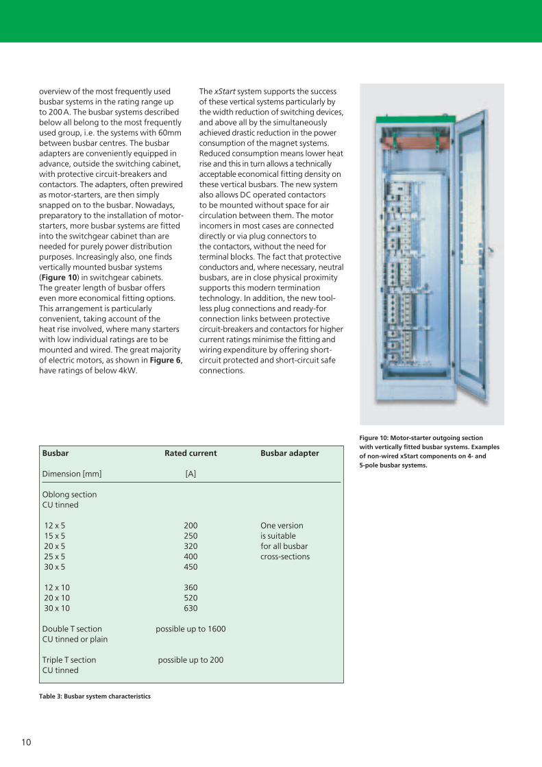
overview of the most frequently used busbar systems in the rating range up to 200 A. The busbar systems described below all belong to the most frequently used group, i.e. the systems with 60mm between busbar centres. The busbar adapters are conveniently equipped in advance, outside the switching cabinet, with protective circuit-breakers and contactors. The adapters, often prewired as motor-starters, are then simply snapped on to the busbar. Nowadays, preparatory to the installation of motor-starters, more busbar systems are fitted into the switchgear cabinet than are needed for purely power distribution purposes. Increasingly also, one finds vertically mounted busbar systems (Figure 10) in switchgear cabinets. The greater length of busbar offers even more economical fitting options. This arrangement is particularly convenient, taking account of the heat rise involved, where many starters with low individual ratings are to be mounted and wired. The great majority of electric motors, as shown in Figure 6, have ratings of below 4kW.
The xStart system supports the success of these vertical systems particularly by the width reduction of switching devices, and above all by the simultaneously achieved drastic reduction in the power consumption of the magnet systems. Reduced consumption means lower heat rise and this in turn allows a technically acceptable economical fitting density on these vertical busbars. The new system also allows DC operated contactors to be mounted without space for air circulation between them. The motor incomers in most cases are connected directly or via plug connectors to the contactors, without the need for terminal blocks. The fact that protective conductors and, where necessary, neutral busbars, are in close physical proximity supports this modern termination technology. In addition, the new tool-less plug connections and ready-for connection links between protective circuit-breakers and contactors for higher current ratings minimise the fitting and wiring expenditure by offering short-circuit protected and short-circuit safe connections.
Busbar Rated current Busbar adapter Dimension [mm] [A] Oblong sectionCU tinned 12 x 5 200 One version 15 x 5 250 is suitable 20 x 5 320 for all busbar 25 x 5 400 cross-sections 30 x 5 450 12 x 10 360 20 x 10 520 30 x 10 630 Double T section possible up to 1600 CU tinned or plain Triple T section possible up to 200 CU tinned
Table 3: Busbar system characteristics
Figure 10: Motor-starter outgoing section with vertically fitted busbar systems. Examples of non-wired xStart components on 4- and5-pole busbar systems.
VER1200_2100-938.indd 10VER1200_2100-938.indd 10 29.10.2008 13:35:23 Uhr29.10.2008 13:35:23 Uhr
11
Changes in systems building brought about by the trend towards decentralisation
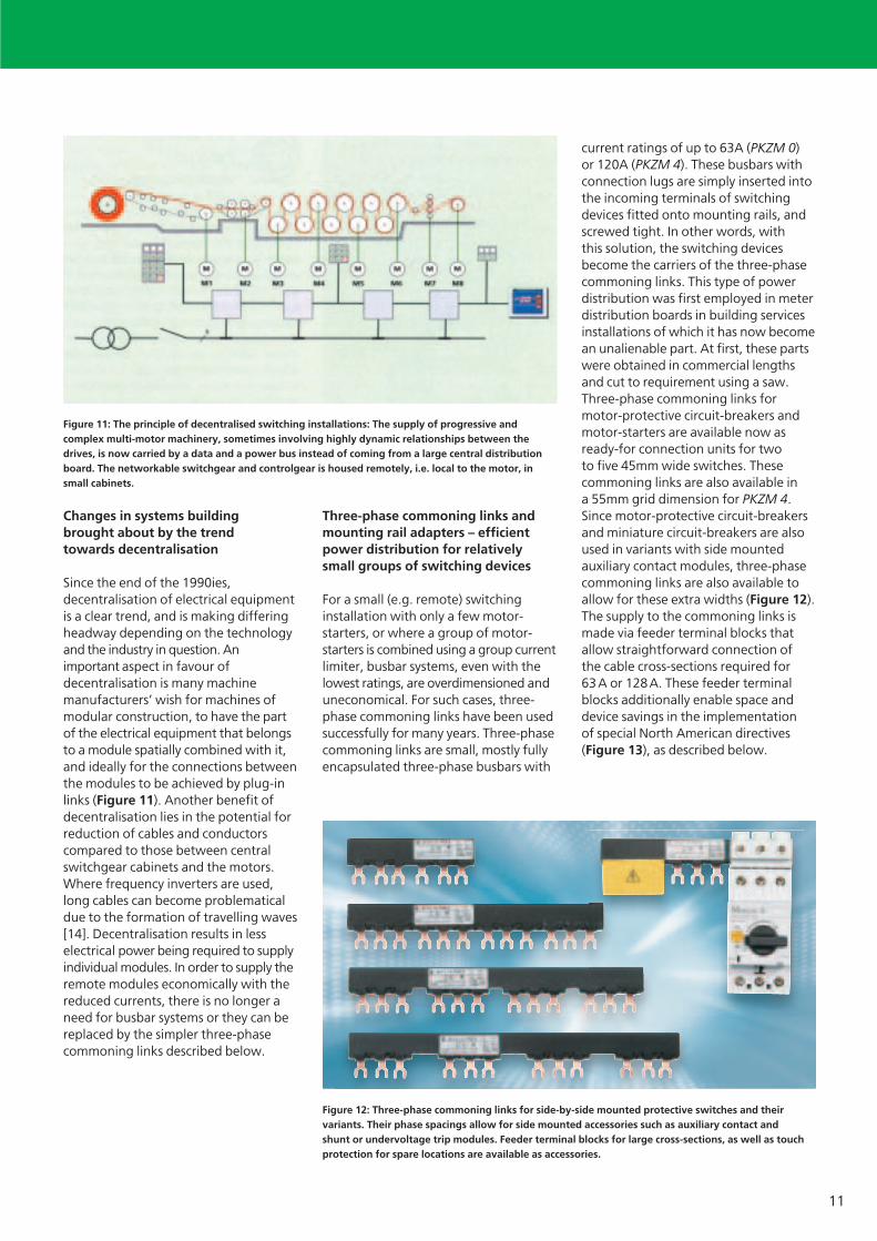
Since the end of the 1990ies, decentralisation of electrical equipment is a clear trend, and is making differing headway depending on the technology and the industry in question. An important aspect in favour of decentralisation is many machine manufacturers’ wish for machines of modular construction, to have the part of the electrical equipment that belongs to a module spatially combined with it, and ideally for the connections between the modules to be achieved by plug-in links (Figure 11). Another benefit of decentralisation lies in the potential for reduction of cables and conductors compared to those between central switchgear cabinets and the motors. Where frequency inverters are used, long cables can become problematical due to the formation of travelling waves [14]. Decentralisation results in less electrical power being required to supply individual modules. In order to supply the remote modules economically with the reduced currents, there is no longer a need for busbar systems or they can be replaced by the simpler three-phase commoning links described below.
Three-phase commoning links and mounting rail adapters – efficient power distribution for relatively small groups of switching devices
For a small (e.g. remote) switching installation with only a few motor-starters, or where a group of motor-starters is combined using a group current limiter, busbar systems, even with the lowest ratings, are overdimensioned and uneconomical. For such cases, three-phase commoning links have been used successfully for many years. Three-phase commoning links are small, mostly fully encapsulated three-phase busbars with
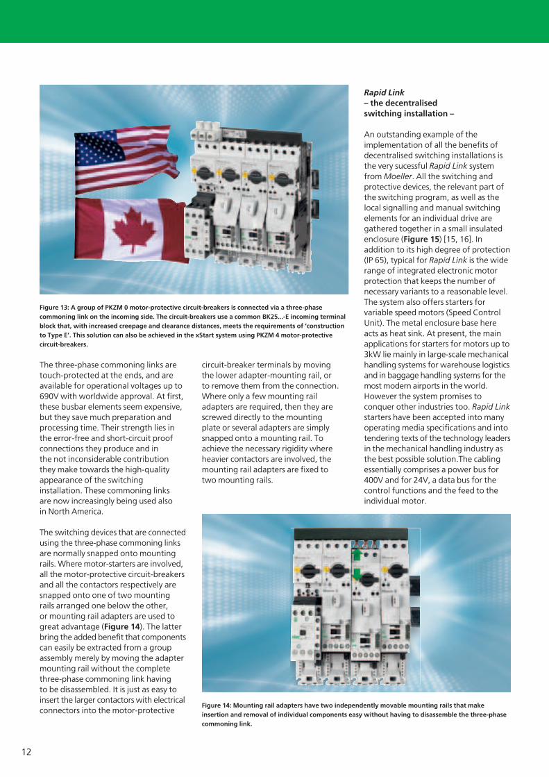
current ratings of up to 63A (PKZM 0) or 120A (PKZM 4). These busbars with connection lugs are simply inserted into the incoming terminals of switching devices fitted onto mounting rails, and screwed tight. In other words, with this solution, the switching devices become the carriers of the three-phase commoning links. This type of power distribution was first employed in meter distribution boards in building services installations of which it has now become an unalienable part. At first, these parts were obtained in commercial lengths and cut to requirement using a saw. Three-phase commoning links for motor-protective circuit-breakers and motor-starters are available now as ready-for connection units for two to five 45mm wide switches. These commoning links are also available in a 55mm grid dimension for PKZM 4. Since motor-protective circuit-breakers and miniature circuit-breakers are also used in variants with side mounted auxiliary contact modules, three-phase commoning links are also available to allow for these extra widths (Figure 12). The supply to the commoning links is made via feeder terminal blocks that allow straightforward connection of the cable cross-sections required for 63 A or 128 A. These feeder terminal blocks additionally enable space and device savings in the implementation of special North American directives (Figure 13), as described below.
Figure 11: The principle of decentralised switching installations: The supply of progressive and complex multi-motor machinery, sometimes involving highly dynamic relationships between the drives, is now carried by a data and a power bus instead of coming from a large central distribution board. The networkable switchgear and controlgear is housed remotely, i.e. local to the motor, in small cabinets.
Figure 12: Three-phase commoning links for side-by-side mounted protective switches and their variants. Their phase spacings allow for side mounted accessories such as auxiliary contact and shunt or undervoltage trip modules. Feeder terminal blocks for large cross-sections, as well as touch protection for spare locations are available as accessories.
VER1200_2100-938.indd 11VER1200_2100-938.indd 11 29.10.2008 13:35:24 Uhr29.10.2008 13:35:24 Uhr
12
The three-phase commoning links are touch-protected at the ends, and are available for operational voltages up to 690V with worldwide approval. At first, these busbar elements seem expensive, but they save much preparation and processing time. Their strength lies in the error-free and short-circuit proof connections they produce and in the not inconsiderable contribution they make towards the high-quality appearance of the switching installation. These commoning links are now increasingly being used also in North America.
The switching devices that are connected using the three-phase commoning links are normally snapped onto mounting rails. Where motor-starters are involved, all the motor-protective circuit-breakers and all the contactors respectively are snapped onto one of two mounting rails arranged one below the other, or mounting rail adapters are used to great advantage (Figure 14). The latter bring the added benefit that components can easily be extracted from a group assembly merely by moving the adapter mounting rail without the complete three-phase commoning link having to be disassembled. It is just as easy to insert the larger contactors with electrical connectors into the motor-protective
circuit-breaker terminals by moving the lower adapter-mounting rail, or to remove them from the connection. Where only a few mounting rail adapters are required, then they are screwed directly to the mounting plate or several adapters are simply snapped onto a mounting rail. To achieve the necessary rigidity where heavier contactors are involved, the mounting rail adapters are fixed to two mounting rails.
Rapid Link– the decentralised switching installation –
An outstanding example of the implementation of all the benefits of decentralised switching installations is the very sucessful Rapid Link system from Moeller. All the switching and protective devices, the relevant part of the switching program, as well as the local signalling and manual switching elements for an individual drive are gathered together in a small insulated enclosure (Figure 15) [15, 16]. In addition to its high degree of protection (IP 65), typical for Rapid Link is the wide range of integrated electronic motor protection that keeps the number of necessary variants to a reasonable level. The system also offers starters for variable speed motors (Speed Control Unit). The metal enclosure base here acts as heat sink. At present, the main applications for starters for motors up to 3kW lie mainly in large-scale mechanical handling systems for warehouse logistics and in baggage handling systems for the most modern airports in the world. However the system promises to conquer other industries too. Rapid Link starters have been accepted into many operating media specifications and into tendering texts of the technology leaders in the mechanical handling industry as the best possible solution.The cabling essentially comprises a power bus for 400V and for 24V, a data bus for the control functions and the feed to the individual motor.
Figure 13: A group of PKZM 0 motor-protective circuit-breakers is connected via a three-phase commoning link on the incoming side. The circuit-breakers use a common BK25...-E incoming terminal block that, with increased creepage and clearance distances, meets the requirements of ‘construction to Type E’. This solution can also be achieved in the xStart system using PKZM 4 motor-protective circuit-breakers.
Figure 14: Mounting rail adapters have two independently movable mounting rails that make insertion and removal of individual components easy without having to disassemble the three-phase commoning link.
VER1200_2100-938.indd 12VER1200_2100-938.indd 12 29.10.2008 13:35:36 Uhr29.10.2008 13:35:36 Uhr

13
The electrical connection technology was designed to allow individual drive modules to be exchanged without interruption of the power and data bus. Flexibility in application, optimised cabling and a particularly high level of accessibility are among the special characteristics of the system. In the ideal case, the cabling is fully pluggable, either using round or flat band cables. The latter can be used with piercing connection elements similar to those used first with the AS-Interface bus. The Disconnect Control Unit is the main and maintenance switch, as well as cable protection in one. In addition, this unit can be used to implement remote Emergency-Stop concepts. The Interface Control Unit represents the interface to the open fieldbus. The Motor Control Unit functions as direct-on line or reversing starter with electronic motor protection from 0.09 to 3kW. The drive specific settings are made simply via AS-Interface or DIP switches. Optionally, there is a Logic Control Unit that can be used as application oriented local small control unit where autonomous preprocessing of the I/O signals is required, for example for actuation of accumulating conveyors. A superordinate control system merely tells the Unit how the goods are to be
transported. In addition, the integrated display shows the operating states as plain text messages. xStart components are also integrated into the Rapid Link system. Any application that can be implemented using the described
system properties of Rapid Link will certainly achieve the highest possible level of rationalisation of its electrical equipment.
Systematic connection = tool-less plug connection
Manual work represents a potential weakness in a control system. It is also highly expensive. The time taken is difficult to calculate and often there are bottlenecks regarding suitable personnel. Where manual work is done under time pressure, errors creep in easily. All these are reasons for seeking practical compromise solutions between manual fitting and automation. There are many repetitive actions involved in control system building. This is where the idea of the tool-less plug-in technology comes in: on each motor-starter, the connection must be made between motor-protective circuit-breaker and contactor. On reversing starters, in addition, the reversing wiring to the second contactor for the main and control circuits must be put in place. Where these links are made using wires the regulations covering operating media specify in many cases that both ends of the connection must be labelled, not to mention the ferrules.
Figure 15: The individual enclosures of the decentralised motor-starter system, Rapid Link, are mounted locally to the drives. Electrical power is supplied error-free via a power and a data bus. Connection to the motor in most cases is also via a plug connector. Looped, round-section cables could be used instead of the flat band power cable shown here.
Figure 16: Connections for the tool-less plug-in technology on PKZM 0 motor-protective circuit-breakers with rotary actuation, for currents up to 16 A, as well as on DIL A contactor relays and DIL M contactors up to 15 A
Rapid LinkRapid Link
PKZM 0 motor-protective circuit-breaker withrotary actuation,up to 16 A
Additional front plugsockets for tool-less plug-in technology
DIL A contactor relays,DIL M contactors up to 15 A
VER1200_2100-938.indd 13VER1200_2100-938.indd 13 29.10.2008 13:35:44 Uhr29.10.2008 13:35:44 Uhr

14
This is mindless work, on which expensive, specialised personnel are wasted.
Up to 15 A, PKZM 0 motor-protective circuit-breakers with rotary actuation, and contactors in the xStart system generally have additional oblong plug sockets on the front (Figure 16). 15 A at 400V equates roughly to 7.5 kW, a rating that is higher than that of most motors in today’s automation technology. On the contactors, even the built-in auxiliary contact modules and coil connections are equipped with the plug connections. Here for example, the reversing interlock in the control circuit is simply plugged in. High-quality springy plug-in lugs ensure reliable electrical connection. The plug connectors reliably cope with the entire current and voltage spectrum, from control circuit connections in the mA range with low control voltages, up to motor currents of 15 A and voltages up to 415 V. The new tool-less plug-in connection technology was developed jointly with the world market leader in electrical plug connectors.
Figure 17 shows the tool-less plug-in connection technology by the example of a direct-on-line starter up to 12A. Mechanical plug modules connect
motor-protective circuit-breakers and contactors to produce stable assemblies that can be securely snap-fitted on to just one top-hat rail. When the plug connector is pulled out, there remains
a visible isolating gap. The user can choose between connection sets for the assembly of standard motor-protective circuit-breakers with standard contactors (PKZM0-XD M12 or PKZM0-XR M12), or, for the most popular control voltages, 230V50HZ / 240V60HZ and 24 VDC, he can have ready assembled and mounted MSC-D-… direct-on-line starters or MSC-R-… reversing starters supplied ex-factory.
The contactor apertures for the tool-less plug-in connectors, as shown in Figure 16, are also suitable for accepting reversing or star-delta bridges. Furthermore, the apertures of the tool-less plug connectors are used for solder pin adapters. Using the solder pin adapter (Figure 18), it is simply possible to plug on circuit boards with direct contact to the main circuit connections and the contactor coil connections, on contactors or reversing contactor combinations. The customer can mount electronic components on these circuit boards for their own applications such as additional functions for delay circuits, pulse circuits or customized networking tasks (keywords: alternative printable contactor combinations).Further modular components that also have plug connections to the contactor
Figure 17: Tool-less plug-in connection technology on a direct-on-line starter with the advantages of secure fixing on just one carrier rail and positive and error-free connection between motor-protective circuit-breaker and contactor. The physical volume of the mechanical link is used for ancillary functions of the tool-less plug-in connection technology in a further development stage of the system.
Figure 18: The new tool-less plug-in connection technology enables pcb’s to be plugged on to switchgear to connect directly with the terminals. The user can design the layout of the printed circuit board and equip it as required.
VER1200_2100-938.indd 14VER1200_2100-938.indd 14 29.10.2008 13:35:56 Uhr29.10.2008 13:35:56 Uhr

15
coils are fitted onto the contactors (Figure 19) and/or the main circuit connections. In this form motor filters for contactors up to15 A or electronic timing relays simply need to be plugged onto the contactors. In addition, it is possible for feedback to be monitored via auxiliary contact modules, or to build in especially dust-proofed, highly fail-safe auxiliary contacts for extra low currents and voltages. The tool-less plug connections thus open up a whole new range of applications for the future.
The system allows a flexible modularity while offering a dependable fixed mounting dimension using standard contactors and motor-protective circuit-breakers. It reduces the costs for fitting and testing, and it increases the serviceability of installations by the facility for rapid exchange of components. The tool-less plug-in connection technology, what is more, does not limit the ways in which components have always been customarily handled / fitted. The system interfaces on contactors and motor-protective circuit-breakers cost the same. New costs only arise from using the cost-efficient plug connectors.But these costs are more than compensated for by the systematic savings described.
The combinations using the tool-less plug-in connection technology are only 45mm or 90mm wide and can be employed to great advantage fitted on busbar adapters. For a sufficient, continuous and defined demand, it will be possible to supply these starters fitted on busbar adapters, ready for connection.
Ready-for-connection starter combinations
One of the main purposes of low-voltage switchgear is the switching and protection of motors. In fact, this is the task of motor-starters, and these are available in a wide variety of versions for standard applications. A number of different technical levels offer from manually operated starters via current and voltage limited solutions to the frequency inverters for variable motor speeds. What is common to most solutions is that they combine several components for the necessary switching and protective functions. Selection of the components is made easier by the selection aids described later. Here, the emphasis is on optimisation of error-free fitting and wiring. Standard, universally applicable components are combined in each case. These standard components are produced in large quantities and therefore offer high, constant quality at favourable prices. The main current bridges, DILM12-XSL or DILM12-XRL, for the contactors <15 A, are inserted into the sockets of the tool-less plug connectors (Figure 20) quickly and in a space-saving manner. The new reversing and star-delta main current bridges for contactors above 15 A and <32 A (DILM32-XRL and DILM32-XSL), have been made significantly more compact (Figures 21, 22) and now also fit between contactors and motor-protective relays.
Figure 19: An enclosure that is plugged onto the contactor and mechanically latched with it, can accommodate standard circuits from the catalogue or customised circuits. These, e.g. an electronic timing relay, are then in direct contact with the coil connections and so enable the switchgear to be monitored if required.
Figure 20: Ready-for-connection fitted and wired switchgear assemblies from the xStart system cut the time needed for fitting and testing.
External 24V DC auxiliary voltage
Thermistor-protective modulebased on
tool-less plug-in technology
Motor with built-inthermistor sensor
VER1200_2100-938.indd 15VER1200_2100-938.indd 15 29.10.2008 13:36:16 Uhr29.10.2008 13:36:16 Uhr
16
The time saving using these prepared bridges in comparison to individual wires should not be underestimated. The contactors are mechanically linked to form a unit using DILM32-XVB or DILM150-XVB clips.
The user can fit and wire all the combinations either by using the mounting and wiring aids offered by Moeller, or by his own preferred method. Particular time-savings can be had by employing combinations already preassembled, ready for connection, as well as functionally tested in Moeller’s own workshops. For a sufficient, continuous and defined requirement, customer-specific combinations can also be built. In order to avoid having to deal with quantities of waste from the packaging of individual assemblies for customised solutions that are often needed in large quantities, it makes sense to supply these in volume packaging rather than individually wrapped.
Switching and protecting motors using UL 508 Type F motor-starters to North American directives – for worldwide application (Self-Protected Combination Motor Controllers)
In the past, the export of switching installations to North America often brought nasty surprises for the installation
and machine manufacturers. The reason was that in North America additional short-circuit protective elements are mandatory, which are not specified by the electrical Standards in the rest of the world. Additional protective devices require extra space in the switchgear cabinet, as well as added coordination, and must be included in the documentation. Taking into account the different switching installation layouts, they result in the manufacture of an undesirable number of system variants. As far as conformance to the Standard is concerned, there are now helpful new layout solutions for motor-starters that support the European type motor-protective circuit-breakers and now enable a uniform cabinet layout for North America and the IEC world. However, alongside these improvements described below, there are still special requirements to be taken into account by exporters to North America, such as mandatory approval of all components and systems, and wiring using AWG cables.
In the USA and Canada a distinction is made, as shown in Table 4, between distribution equipment and devices for the switching of industrial loads, i.e. industrial control equipment. Separate Standards apply to these two types of equipment, also making differing demands on it. Above all, the specifications for creepage and clearance distances in air and for
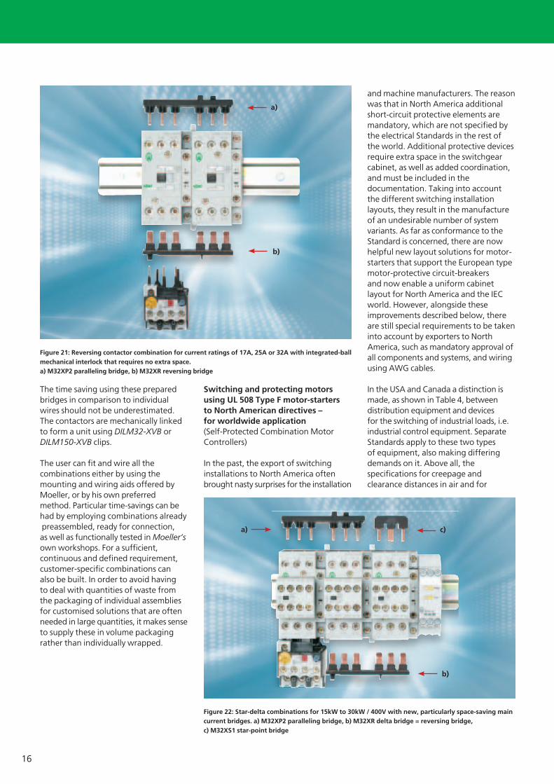
Figure 21: Reversing contactor combination for current ratings of 17A, 25A or 32A with integrated-ball mechanical interlock that requires no extra space.a) M32XP2 paralleling bridge, b) M32XR reversing bridge
Figure 22: Star-delta combinations for 15kW to 30kW / 400V with new, particularly space-saving main current bridges. a) M32XP2 paralleling bridge, b) M32XR delta bridge = reversing bridge, c) M32XS1 star-point bridge
a) c)
b)
a)
b)
VER1200_2100-938.indd 16VER1200_2100-938.indd 16 29.10.2008 13:36:40 Uhr29.10.2008 13:36:40 Uhr
17
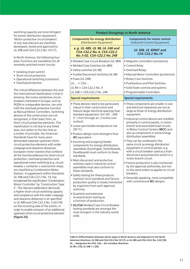
switching capacity are more stringent for power distribution equipment. ‘Motor-protective circuit-breakers’ of any manufacture are classified, developed, tested and approved to UL 508 and CSA-C22.2 No.14 [17].
In North America, the following four basic functions are mandatory for all remotely switched motor circuits:
Isolating (main switch)• Short-circuit protection• Operational switching (contactor)• Overload protection •
The critical difference between this and the international classification is that in America, the motor-protective circuit-breakers marketed in Europe, such as PKZM or comparable devices, can only fulfil the overload protective function as Manual Motor Controllers. Switching devices of this construction are not recognised, in their basic form, as short-circuit protective elements. This classification is not due to any failed tests, but rather to the fact that as a matter of principle, the American Standards have for many years demanded separate upstream short-circuit protective elements with wider creepage and clearance distances. European motor-starters that combine all the functions/devices for short-circuit protection, overload protection and operational motor switching (e.g. circuit-breaker + contactor + overcurrent relay), are classified as Combination Motor Starters. A supplement within Standards UL 508 and CSA-C22.2 No. 14, has broadened the classification ‘Combination Motor Controller’ by ‘Construction Type E’. The relevant addendum demands a higher short-circuit switching capacity and compliance with the wider creepage and clearance distances in air specified in UL 489 and CSA-C22.2 No. 5-02 [18] on the incoming side of the switch, in order to enable omission of an additional upstream short-circuit protective element (Figure 23).
Table 4: Differentiation between device types in North America and alignment to the North American directives, UL 508 and CSA-C22.2 No.14 [17], or UL 489 and CSA-C22.2 No. 5-02 [18]. UL ... designates the USA, CSA... the Canadian directives.UL 98 = [19], UL 248-1 = [20]
Product Groupings in North America
Components for energy distribution(Distribution Equipment)
Components for motor control(Industrial Control Equipment)
e. g. UL 489, UL 98, UL 248 and CSA-C22.2 No. 4, CSA-C22.2 No. 5-02, CSA-C22.2 No. 248
UL 508, UL 60947 and CSA-C22.2 No.14
• Molded Case Circuit Breakers (UL 489)
• Molded Case Switches (UL 489)
• Safety switches (UL 98)
• Fusible Disconnect Switches (UL 98)
• Fuses (UL 248)
UL… � CSA…
UL 98 � CSA-C22.2 No. 4
UL 248 � CSA-C22.2 No. 248
• Magnetic controllers (contactors)
• Control Relay
• Overload Relays
• Manual Motor Controllers (protectors)
• Rotary Cam Switches
• Pushbuttons and Pilot Switches
• Solid State controls and systems
• Programmable Controllers
Special requirements: Special requirements:
• These devices need to be particularly robust in their construction and feature larger electrical spacings than standard equipment: (for 301...600 V: 1 Inch through air, 2 Inches over surface).
• Lower permissible temperature rise(50 °C).
• Product design more divergent than IEC equivalent.
• Incoming and outgoing feeder components for energy distribution assemblies (Switchgear, Switchboards, Panelboards) must conform to these standards.
• Main disconnect and protective switches used in industrial control assemblies must also conform tothese standards.
• Safety testing for these products maintain strict standards and factory production quality is closely monitored by inspectors from each approval authority.
• Quarterly and extensive re-examination testing as a function of production.
• UL/CSA Molded Case Circuit Breaker testing standards are amongst the most stringent in the industry world-wide.
• These components are smaller in size and electrical clearances are not as large as those of energy distribution equipment.
• Industrial control devices are installed primarily in control panels, in motor branch and associated load circuits, in Motor Control Centers (MCC) and also as components in some energy distribution assemblies.
• They can be combined in the same circuit as energy distribution equipment in control panels, e.g. with a circuit breaker used as a main disconnect and protective switch in a motor branch circuit.
• Factory production is also monitored by the approval authorities, but not to the same extent as applies to circuit breakers.
• Generally speaking, more compatible with conventional IEC-designs.
VER1200_2100-938.indd 17VER1200_2100-938.indd 17 29.10.2008 13:36:52 Uhr29.10.2008 13:36:52 Uhr

18
The PKZM 0 and PKZM 4 motor-protective circuit-breakers enable interesting implementation possibilities as UL 508 Type E starters within the xStart system. In modular systems, PKZM 0 or PKZM 4 together with the three-phase commoning links described and special BK25...-E or BK50/3-PKZ4-E feeder terminal blocks (Figure 13) can be used. These feeder blocks are decisive for Type E approval. But they must have the enhanced creepage and clearance distances to UL 489. The fact that the three-phase commoning links are permitted, is a welcome additional benefit. Since they allow several motor-protective circuit-breakers to be supplied on the incoming side via three-phase commoning links, these solutions enable economical and space-saving control system layouts as they are customary in the IEC world. It is the new, now slightly bigger feeder terminal block that makes the difference to the previous international solution, and can now be used in all switching installations worldwide. It must be noted that UL 508 Type E starters must be used only in earthed mains systems (e.g. 480Y/277 V). The utilisation of UL 508 Type E starters brings the following benefits:
Simplified engineering, since there • is no need for coordination with an (often unknown) external upstream short-circuit protective element, and
because no such element needs to be built into the system additionally, space saving in terms of device fitting, No wiring between additional • components, Lower equipment cost and therefore • overall cost of the switching installation, A rapprochement to the control • system construction usual in the IEC world.
The described ‘manual UL 508 Type E’ protective devices, e.g. PKZM0-.. with BK25-..-E incoming feeder terminal, are merely an interim solution for the export problem. As a rule with machine equipment, motors are to be switched automatically using contactors. This is where the next expansion of the directive helps out. ‘Manual UL 508 Type E starters’ become UL 508 Type F Combination Starters (Figure 24) by combination with contactors. As shown in Figure 25, ‘Type F Combination Starters’ also need no series protective device. It must be noted that Type F starters, like Type E starters, must be used only in earthed mains systems (e.g. 480Y/277 V). ‘UL 508 Type F’ starters are at present available only for the USA, because Canada has not yet adopted the changed directive.
A purely modular system, where the manufacturer or the builder of the switching installation combines approved modules at his own responsibility, does not exist in North America. Only combinations that are named in the Moeller Approvals files are acceptable. In the Approvals files, Moeller has included all the admissible or sensible combinations that produce Type-starters. All the three-phase commoning links already had UL and CSA approvals.
Figure 24: Example of UL 508 Type F Combination Starter combined from manually operated UL 508 Type E devices and contactors. The combinations have to be listed in switchgear manufacturer’s Approvals files.
Figure 23: UL 508 Type E devices to UL / CSA directives, due to their enhanced creepage and clearance distances on the incoming side of the motor-protective circuit-breaker and their high switching capacity, provide all four functions of a motor-starter, and the upstream protective device therefore, can be omitted. Type E devices are designated in North America as Self-Protected Motor Starters.
UL 508 ‘Type E’
‘Type E’- devices fulfil all four functions (isolating, short-circuit protection, overload protection, operational switching), therefore the upstream protective device can be omitted.
Upstream protective device
VER1200_2100-938.indd 18VER1200_2100-938.indd 18 29.10.2008 13:36:52 Uhr29.10.2008 13:36:52 Uhr

19
„Type F“-Geräte
1 = (Manual) „Type E“-Gerät
When selecting combinations, it makes sense to consult the current selection lists from manufacturers, since these are constantly developing and at times offer considerable technical and economic benefits. Detailed information regarding the difficult topic of ‘Motor-starters for utilisation in North America’ is offered in another article [21].
The smallest switching installation – motor-protective circuit-breaker in a surface mounting enclosure –
Among the most versatile switching and protective devices are the motor-protective circuit-breakers.They are in themselves already complete motor-starters and represent the first choice for many applications not involving very frequent or remote switching.
UL 508 ‘Type F‘
‘Type F’-devices are combinations of Manual ‘Type E’ devices and additional contactors.Here too, the series element can be omitted.
Upstream protective element
1 = (Manual) ‘Type E’ device2 = Contactor
Figure 25: ‘Type F Combination Starters’ provide all four functions of a motor-starter to UL 508, the upstream protective device can be omitted here as well therefore.
Table 5: Motor-protective circuit-breakers become universal switching and protective devices due to their design characteristics.
Characteristics that make motor-protective circuit-breakers into universal switching and protective devices
Basic properties of PKZM 0 and PKZM 4 motor-protective circuit-breakers:
Circuit-breakers optimised for motor protection,• Operational switching by hand,• Clear indication of the switch position,• Current-dependent, inherent short-circuit protection possible up to 150kA,• At higher rated currents, application oriented short-circuit protection up to 50kA at 400V or group protection for • several breakers,Usable up to 690V,• Personnel protection through all-pole de-energization and quick tripping,• Fixed, simultaneous short-circuit protection for cables and operating media,• Adjustable overload protection for cables and operating media,• Suitable for rated currents up to 65A, i.e. for 90 % of all three-phase motors,• Equally suited to the switching and protection of resistive loads,• Their phase-failure sensitivity makes them suitable for the protection of EEx e motors, with approval to ATEX 100a [22],• Short recovery time after fault removal,• Suitable for world markets, with all the necessary approvals and acceptances,•
Optional functions of PKZM 0 and PKZM 4 motor-protective circuit-breakers:
Mounting and encapsulation with high degree of protection,• Occasional remote tripping,• Protection by undervoltage trips against automatic restart, • Usable as main switch or Emergency-Stop switch in the main circuit,• Isolation of the Emergency-Stop circuit by early-make auxiliary contacts,• Versatile locking facilities,• Multiple, differential status indication, even a networkable solution,• Comprehensive system accessories.•
VER1200_2100-938.indd 19VER1200_2100-938.indd 19 29.10.2008 13:36:58 Uhr29.10.2008 13:36:58 Uhr

20
All the many functions are combined in the smallest of spaces in a single device as shown in Table 5. Motor-protective circuit-breakers are small circuit-breakers developed and tested to the Standard IEC / EN 60 947-2 [23] and the motor-starter Directive IEC / EN 60 947-4-1 [24]. The isolating characteristics comply with IEC / EN 60 947-3 [25].
The PKZM is synonymous in the market with the term motor-protective circuit-breaker. PKZM motor-protective circuit-breakers in decentralised electrical systems are increasingly used as main or Emergency-Stop switches in the main current circuit. Breakers with rotary drives offer benefits for use inside the switching cabinet (Figure 26, middle and left), with their ratings now expanded up to 65A. The typical door-coupling rotary handles with or without door interlocking are designed for this type of fitting. Extension shafts with centring guides facilitate adaptation to various cabinet depths.
Within the new xStart product system from Moeller, the popular pushbutton actuation was being reintroduced. When the switch is fitted directly to simple machines, actuation by pushbutton is the most ergonomicand efficient
(Figure 26, right). In an emergency, the breaker can thus be simply ‘knocked out’. Many users want the pushbutton actuation because they do not regard toggle or rocker actuations as equivalent. In addition to the rotary operation, Moeller is therefore bringing back the classical push actuation in the shape of the PKZM 01 for currents up to 16A, complete with mushroom button for Emergency-Stop actuation on simple machines. PKZM can be used either
open, in an insulated surface mounting enclosure with high degree of protection, or fitted on the proven flush mounting plate for mounting in the machine or instrument enclosure (Figure 27).
Handy motor-starter selection aid
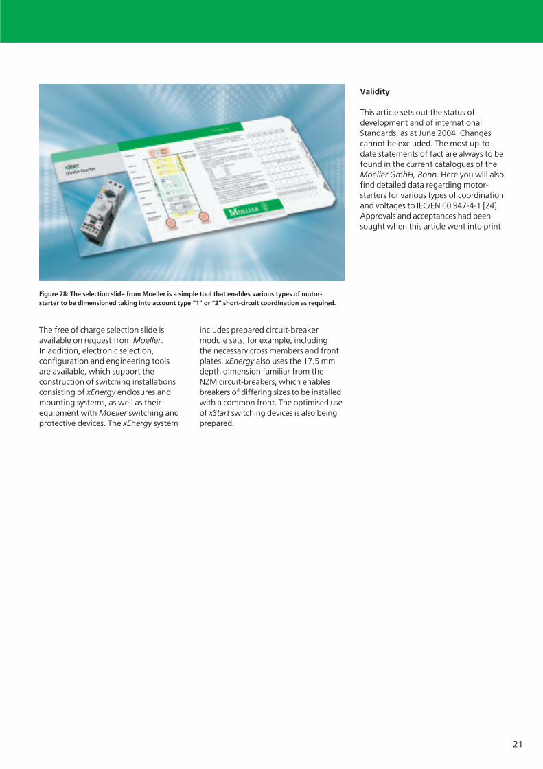
Complementary to the comprehensive selection pages in the Moeller Main Catalogue, Moeller also offers a PC-based electronic selection program for motor-starters. In addition to the different operational voltages, short-circuit ratings and types of coordination [24], it takes into account fuseless as well as fused combinations. Moeller offers this little program free of charge on the Internet (www.moeller.net). For the practician, there is also the well-known and popular selection slide card that has been issued for many years now. It guides you to the correct device dimensions with short-circuit coordination to types “1” or “2”, via the required operational voltage and the motor rating, without the need for a PC (Figure 28). In addition, it shows standard cable cross-sections and admissible cable lengths to achieve Standard-compliant tripping of the protective elements, and how they can be adapted as required for the installation conditions on site. The selection slide can be provided with several different slide inserts giving the figures for direct-on line and reversing starters, as well as star-delta starters.
Figure 26: Shown middle and left are motor-protective circuit-breakers PKZM 4 and PKZM 0 with rotary drives, on the right the new PKZM 01 with pushbutton actuation.
Figure 27: The smallest, complete switching installations: fitted into surface mounting enclosures, with or without mushroom actuator for Emergency-Stop, or PKZM 01 fitted directly into the machine enclosure on a flush mounting plate.
VER1200_2100-938.indd 20VER1200_2100-938.indd 20 29.10.2008 13:37:00 Uhr29.10.2008 13:37:00 Uhr
21
The free of charge selection slide is available on request from Moeller. In addition, electronic selection, configuration and engineering tools are available, which support the construction of switching installations consisting of xEnergy enclosures and mounting systems, as well as their equipment with Moeller switching and protective devices. The xEnergy system
includes prepared circuit-breaker module sets, for example, including the necessary cross members and front plates. xEnergy also uses the 17.5 mm depth dimension familiar from the NZM circuit-breakers, which enables breakers of differing sizes to be installed with a common front. The optimised use of xStart switching devices is also being prepared.
Validity
This article sets out the status of development and of international Standards, as at June 2004. Changes cannot be excluded. The most up-to-date statements of fact are always to be found in the current catalogues of the Moeller GmbH, Bonn. Here you will also find detailed data regarding motor-starters for various types of coordination and voltages to IEC/EN 60 947-4-1 [24]. Approvals and acceptances had been sought when this article went into print.
Figure 28: The selection slide from Moeller is a simple tool that enables various types of motor-starter to be dimensioned taking into account type “1” or “2” short-circuit coordination as required.
VER1200_2100-938.indd 21VER1200_2100-938.indd 21 29.10.2008 13:37:13 Uhr29.10.2008 13:37:13 Uhr
22
I/ON
X
12
3
10
45
9
11
87
8
12
6
SmartWire – connecting motor starters instead of wiring
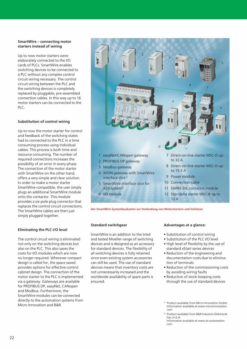
Up to now motor starters were elaborately connected to the I/O cards of PLCs. SmartWire enables switching devices to be connected to a PLC without any complex control circuit wiring necessary. The control circuit wiring between the PLC and the switching devices is completely replaced by pluggable, pre-assembled connection cables. In this way up to 16 motor starters can be connected to the PLC.
Substitution of control wiring
Up to now the motor starter for control and feedback of the switching states had to connected to the PLC in a time consuming process using individual cables. This process is both time and resource consuming. The number of required connections increases the possibility of an error in every phase. The connection of the motor starter with SmartWire on the other hand, offers a very simple and clear solution. In order to make a motor starter SmartWire-compatible, the user simply plugs an additional SmartWire module onto the contactor. This module provides a six-pole plug connector that replaces the control circuit connections. The SmartWire cables are then just simply plugged together.
Eliminating the PLC I/O level
The control circuit wiring is eliminated not only on the switching devices but also on the PLC. This also saves the costs for I/O modules which are now no longer required. Wherever compact design is called for, the space saved provides options for effective control cabinet design. The connection of the motor starter to the PLC is implemented via a gateway. Gateways are available for PROFIBUS DP, easyNet, CANopen and Modbus. Furthermore, the SmartWire modules can be connected directly to the automation systems from Micro Innovation and B&R.
Standard switchgear
SmartWire is an addition to the tried and tested Moeller range of switching devices and is designed as an accessory for standard devices. The flexibility of all switching devices is fully retained since even existing system accessories can still be used. The use of standard devices means that inventory costs are not unnecessarily increased and the worldwide availability of spare parts is ensured.
Advantages at a glance:
• Substitution of control wiring• Substitution of the PLC I/O level• High level of flexibility by the use of
standard xStart series devices• Reduction of the engineering and
documentation costs due to elimina-tion of terminals
• Reduction of the commissioning costs by avoiding wiring faults
• Reduction of stock-keeping costs through the use of standard devices
1 easyNet/CANopen gateway
2 PROFIBUS DP gateway
3 Modbus gateway
4 XI/ON gateway with SmartWire interface slice1)
5 SmartWire interface slice forX20 system2)
6 I/O module
7 Direct-on-line-starter MSC-D up to 32 A
8 Direct-on-line-starter MSC-D up to 15.5 A
9 Power module
10 Connection cable
11 SWIRE-DIL contactor module
12 Star-delta starter MSC-R up to 12 A
1) Product available from Micro Innovation GmbH. Information available at www.microinnovation.
com2) Product available from B&R Industrie-Elektronik
Ges.m.b.H. Information available at www.br-automation.com
Der SmartWire Systembaukasten zur Verbindung von Motorstartern und Schützen
VER1200_2100-938.indd 22VER1200_2100-938.indd 22 29.10.2008 13:37:15 Uhr29.10.2008 13:37:15 Uhr

23
Further Literature:
[1] Product information “xStart: Efficient solutions for the motor circuit“W1200+2100-7548DMoeller GmbH, Bonn, 04/2004
[2] Specialist catalogue “Type-tested switching installation system for the infrasctructure in buildings, up to 4000A“FK4810-1143D,Moeller GmbH, Bonn, 04/2004
[3] “Prepare for the future. Use xEnergy for switching“W4600-7553D,Moeller GmbH, Bonn, 04/2004
[4] Wolfgang Esser,“Switching and protective devices in machine control systems“The magazine for electrical practitioners, Berlin 57 (2003) 11
[5] Wolfgang Esser,“Chief applications for circuit-breakers“The magazine for electrical practitioners, Berlin 57 (2003) 9
[6] Wolfgang Esser, Dr. Johannes Meissner,“Switching powerful operating media economically usingvacuum contactors“VER2100-929D,Moeller GmbH, Bonn, 2003
[7] IEC 60 439-1, DIN EN 60 439-1,VDE 0660 Part 500: 2000-08,“Low-voltage switchgear assemblies – Part 500: Type-tested and partially type-tested combinations.“VDE-Verlag, Berlin-Offenburg
[8] IEC 60 439-3, DIN EN 60 439-3(VDE 0660 Teil 504): 2002-05,“Low-voltage switchgear assemblies – Part 3: Special requirements of low-voltage switchgear assemblies to which unqualified operators have access – Service distribution boards“VDE-Verlag, Berlin-Offenburg
[9] IEC / EN 60 204-1, “Machine safety – Electrical equipment of machines– Part 1: General requirements “
[10] Wolfgang Esser,“The increasing importance of communication in circuit-breakers“The magazine for electrical practitioners, Berlin 57 (2003) 1,Special edition VER 1230-930,Moeller GmbH, Bonn
[11] Wolfgang Esser,“Software solutions improve the economy of automated machines and systems“Automation technology in practice, 44 (2002) Volume 9 atp
[12] Wolfgang Esser,“xStart, the new generation of motor-starters, –again with application-orientated special features!“,VER 2100-937 D,Moeller GmbH, Bonn, 2004
[13] IEC 60 715, DIN EN 60 715: 2001“Dimensions of low-voltage switchgear, standard mounting rails for mechanically securing electrical devices in switching installations “
[14] Wolfgang Esser,“Moving More than MotorsAnalysis and development of drives for machine and system builders.“VER 2100+2300-920 D,Moeller GmbH, Bonn, 2000
[15] Manfred Hilger“RAPID LINK: The quick connection for the materials flow“Special excerpt from the ETZ magazine, VER 0000-927D,Moeller GmbH, Bonn, 02 /2002
[16] Otmar Feurstein,“Waiting efficiently – starting remotely“Special excerpt from the materials handling magazine, VER 0000-933D,Moeller GmbH, Bonn, 07/2003
[17] USA: UL 508, „Industrial Control Equipment”Canada: CSA-C22.2 No. 14, “Industrial Control Equipment, Industrial Products”
[18] USA: UL 489, “Molded Case CircuitBreakers, Molded Case Switchesand Circuit Breaker Enclosures“Canada: CSA-C22.2 No. 5-02, “Moulded Case Circuit Breakers“
[19] UL 98, Standards for Safety,“Enclosed and Dead-Front Switches”
[20] UL 248-1 … 16, Standards forSafety, “Low Voltage Fuses“
[21] Wolfgang Esser,“Special considerations governing the application of Manual Motor Controllers and Motor Startersin North America“,VER1210+1280-928GBMoeller GmbH, Bonn, 2003,or in the Internet: German: http://www.moeller.net/binary/ver_motor-starterna_de.pdf,English: http://www.moeller.net/binary/ver_motor-starterna_en.pdf
[22] ATEX 100a, Directive 94/9/EG, dated 23.3.94, for the harmonisation of statutory regulations within member states for devices and protective systems for Standard-compliant use in potentially explosive areas, ABI. L 100 dated 19.4.1994
[23] IEC / EN 60 947-2 and DIN VDE 0660 Part 101 “Low-voltage switchgearPart 2: Circuit-breakers“
[24] IEC / EN 60 947-4-1 and DIN VDE 0660 Part 102 “Low-voltage switchgearPart 4-1: Electromechanical contactors and motor-starters“
[25] IEC / EN 60 947-3 and VDE 0660Part 107 “Low-voltage switchgearPart 3: “Load-break switches, isolators, switch-disconnectors and fuse combination units “
VER1200_2100-938.indd 23VER1200_2100-938.indd 23 29.10.2008 13:37:17 Uhr29.10.2008 13:37:17 Uhr
Moeller addresses worldwide:www.moeller.net/address
E-Mail: [email protected]: www.moeller.net
www.eaton.com
Issued by Moeller GmbHHein-Moeller-Str. 7-11D-53115 Bonn
© 2008 by Moeller GmbHSubject to alterationsVER2100-938GB ip 10/08Printed in Germany (10/08)Article No.: 289194
Eaton’s electrical business is a global leaderin electrical control, power distribution,uninterruptible power supply and industrialautomation products and services.
Eaton’s global electrical brands, includingCutler-Hammer®, MGE Office ProtectionSystems™, Powerware®, Holec®, MEM®,Santak and Moeller, provide customer-drivenPowerChain Management® solutions to servethe power system needs of the industrial,institutional, government, utility, commercial,residential, IT, mission critical and OEMmarkets worldwide.
www.eaton.com
VER1200_2100-938.indd U24VER1200_2100-938.indd U24 29.10.2008 13:34:51 Uhr29.10.2008 13:34:51 Uhr
Related Documents