4/5/2012 1 An Introduction to Modern Surveying Techniques A. K. Sarma Civil Engineering Department Indian Institute of Technology Guwahati History of Surveying • What is surveying • History of surveying techniques – In ancient Egypt (3000 BCE), when the Nile River overflowed its banks and washed out farm boundaries, boundaries were re-established by surveyor, through the application of simple geometry. • History of surveying in India – Some form of mapping was practiced in India during the Indus Civilization (ca. 2500–1900 BCE). – Construction of large-scale plans and other cartographic works has occurred continuously at least since the late Vedic age (first millennium BCE) Modernization • Development in other field of science – Modernization in surveying equipments – Modernization in surveying technique • Many a time both goes hand in hand – Example: Triangulation Trilateration Survey Equipments and Systems • Rope, measuring tap • Chain • Compass • Plane Table • Level • Theodolite • Electronic theodolite • EDM (Electronic Distance Measuring Equipment) • Total Station, Automatic Total Station • Sounding equipments (Hydrographic survey) • Aerial Photogrammetric survey (1858, 1906) • Satellite Remote Sensing(1972, 1988(India)) • GPS, DGPS • GIS has improved utility of Remote Sensing and GPS

Welcome message from author
This document is posted to help you gain knowledge. Please leave a comment to let me know what you think about it! Share it to your friends and learn new things together.
Transcript

4/5/2012
1
An Introduction to Modern Surveying Techniques
A. K. Sarma
Civil Engineering Department
Indian Institute of Technology Guwahati
History of Surveying
• What is surveying
• History of surveying techniques – In ancient Egypt (3000 BCE), when the Nile River
overflowed its banks and washed out farm boundaries, boundaries were re-established by surveyor, through the application of simple geometry.
• History of surveying in India– Some form of mapping was practiced in India during
the Indus Civilization (ca. 2500–1900 BCE).
– Construction of large-scale plans and other cartographic works has occurred continuously at least since the late Vedic age (first millennium BCE)
Modernization
• Development in other field of science
– Modernization in surveying equipments
– Modernization in surveying technique
• Many a time both goes hand in hand
– Example: Triangulation Trilateration
Survey Equipments and Systems• Rope, measuring tap
• Chain
• Compass
• Plane Table
• Level
• Theodolite
• Electronic theodolite
• EDM (Electronic Distance Measuring Equipment)
• Total Station, Automatic Total Station
• Sounding equipments (Hydrographic survey)
• Aerial Photogrammetric survey (1858, 1906)
• Satellite Remote Sensing(1972, 1988(India))
• GPS, DGPS
• GIS has improved utility of Remote Sensing and GPS

4/5/2012
2
Fundamentals of EDM
• For distance measuring EDM uses either
– Infrared (light wave) [ 0.5 to 20Km]
– Microwaves (radio wave) [up to 50Km]
• Microwave requires transmitter/receiver at
both end
• Infrared requires a reflector at one end
• EDM can be mounted on a standard
theodolite or Electronic theodolite
Fundamentals of Electronic Theodolite
• It contains circular encoders, which can sense the rotation of the spindles and the telescope
• These rotations are converted to horizontal and vertical angles and displayed digitally
• The angle recorded can be entered in filed book or can be stored in digital form and can be downloaded to a computer for future use
• Circle can be set to zero by simply pressing the button
• Laser theodolite has additional facility for more accurately bisecting the target.
Fundamentals of Total Station
• Basically TS (also called Electronic Techeometer) is a combination of EDM and Electronic Theodolite
• They are equipped with a microprocessor for reduction of observed data
• It can display– horizontal angle, vertical angle, slope distance
– Horizontal distance, elevation difference,
– Coordinates
• Automatic Total Station has – motorized EDM and Theodolite, and
– Automatic Target Reorganization
– This makes the survey a single man job
Art and Science of obtaining
information about an object
without being in direct physical
contact with the object
Fundamentals of Remote Sensing
4/5/2012
3
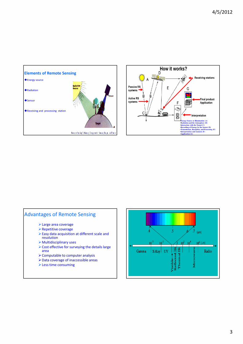
Elements of Remote Sensing
�Energy source
�Radiation
�Sensor
�Receiving and processing station
•Energy Source or Illumination (A)
•Radiation and the Atmosphere (B)
•Interaction with the Target (C)
•Recording of Energy by the Sensor (D)
•Transmission, Reception, and Processing (E)
•Interpretation and Analysis (F)
•Application (G)
Advantages of Remote Sensing
�Large area coverage
�Repetitive coverage
�Easy data acquisition at different scale and resolution
�Multidisciplinary uses
�Cost effective for surveying the details large area
�Computable to computer analysis
�Data coverage of inaccessible areas
�Less time consuming
4/5/2012
4
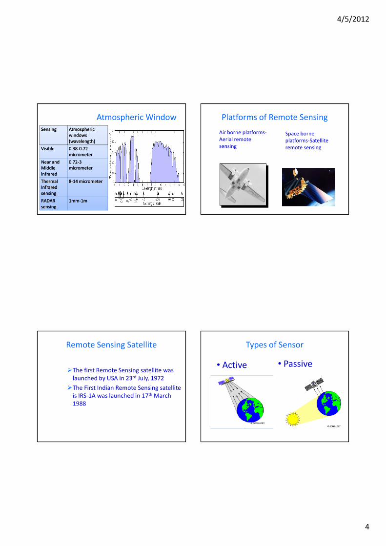
Atmospheric Window
SensingSensing Atmospheric Atmospheric
windows windows
(wavelength)(wavelength)
VisibleVisible 0.380.38--0.72 0.72
micrometermicrometer
Near and Near and
Middle Middle
infraredinfrared
0.720.72--3 3
micrometermicrometer
Thermal Thermal
Infrared Infrared
sensingsensing
88--14 micrometer14 micrometer
RADAR RADAR
sensingsensing
1mm1mm--1m1m
Platforms of Remote Sensing
Air borne platforms-
Aerial remote
sensing
Space borne
platforms-Satellite
remote sensing
Remote Sensing Satellite
�The first Remote Sensing satellite was
launched by USA in 23rd July, 1972
�The First Indian Remote Sensing satellite
is IRS-1A was launched in 17th March
1988
Types of Sensor
• Active • Passive
4/5/2012
5
Passive Sensor Vs. Active Sensor
Passive� Sun is the source of illumination� Operates in the visible and infrared region of the
electromagnetic spectra
Active� Own energy source for illumination
� Can use wavelengths (1mm to 100m) that are not sufficiently provided by the sun
� All weather capability to acquire data
� Day and night capability to acquire data
� Have better control the way is illuminatedExample:
RADAR( Radio Detection and Ranging)
LIDAR (Light Detection and Ranging)
RESOLUTIONQuality of information derived from RS images stronglyinfluenced by spatial, spectral, radiometric and temporalresolution of the sensor
• Spatial Resolutioninstrument resolving power needed to spatially discriminatethe smallest object
• Spectral resolutionencompasses the width of bands used from the wavelengthsof the EM spectrum.
• Radiometric resolutionquantify No. of discernible signal levels in a band, {sensor’sability to discriminate radiance differences (NE∆ρ)}
• Temporal resolutiontime interval between imaging collections over the samegeographic location
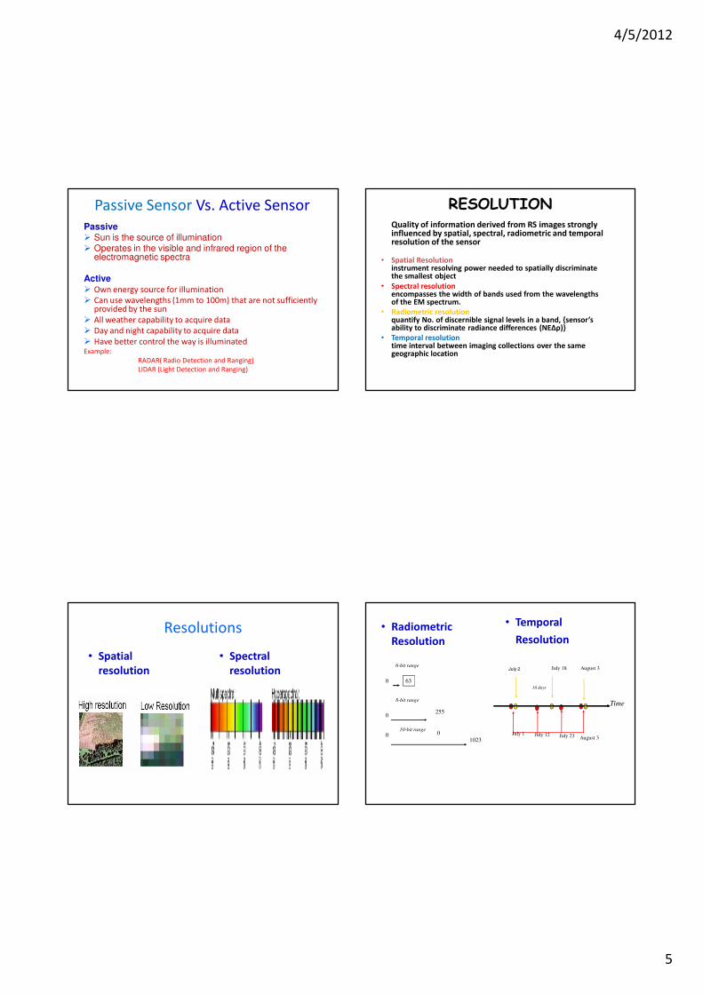
Resolutions
• Spatial
resolution
• Spectral
resolution
• Radiometric
Resolution
• Temporal
Resolution
0July 23
0
10-bit range
0 63
8-bit range
255
10230
6-bit range
Time
July 1 July 12August 3
16 days
July 18 August 3July 2

4/5/2012
6
Interaction of EMR with atmosphere
• Transmission
• Scattering
• Reflection
• Absorption
SpectralReflectance
High
Spectral Region
Blue Green Red Near IR Mid IR
Water
Vegetation
Soil
Spectral Signature
Estimating Elevation Information
• How elevations are measured
– Single image analysis
– Analyzing image pair
• Stereo Image
• What kind of errors there can be
Scale Variation
2 cm
• Occurs in all photography
Scale varies across the photography
6 cm
House width = 8m
Scale is 1:400
Scale is 1:133

4/5/2012
7
Scale Variation
• Same effect seen in vertical photography
House width constant (8m), width in photographs varies,
therefore scale varies
Sensor Attitude/Orientation
Oblique
More Oblique
Vertical
2
3
11
Internal Sensor Errors
Lens distortion and errors cause the light rays to deviate
IMAGE or EXPOSURE PLANE
Stereo Pair• A block should have at least one pair of images which
overlap:
Stereo Pair
Overlap Region
60% Overlap

4/5/2012
8
Global Positioning System: Principle and Applications
Location of an un-know point in a 2D plane with reference to
object in the same plane
Working Principle of GPS
Location of an un-known point in 3D Space
Distance =
Speed of light x
time
Distance = Speed of
sound x travel time
Distance =
Speed of the signal
X
Time to receive the
signal
Determining Location with the help of satellite
Unknowns are:
Horizontal position: X
and Y coordinates
Vertical Position: Z
coordinate
Receiver Clock Error

4/5/2012
9
Importance of
Time Synchronization of Clocksfor
Accuracy in Distance [Time required for a signal to reach receiver from a
overhead satellite position is just 0.06s]
Location of a point with reference to satellite
• Need minimum of four satellites whose positions are known at the time of measurement
• US Defense Department launched 24 satellites (NAVSTAR GPS (Navigation Satellite and Ranging GPS (1978-94)) in such a way that at least 6 satellites remain in view from any point of earth surface at any instant of time
• Distance from the satellites to the receiver need to be calculated accurately
Need of 4 Satellites• Measured pseudo-ranges are contaminated by the
satellite and receiver clock synchronization errors
• Correcting the satellite clock errors may be done by applying the satellite clock correction in the navigation message
• The receiver clock error is treated as an additional unknown parameter in the estimation process
• Thus unknowns are: three for the receiver coordinates and one for the receiver clock error.
• As the satellite coordinates are given in the WGS 84 system, the obtained receiver coordinates will also be in the WGS 84 system

4/5/2012
10
Datum, Mean Sea Level, Geoid…• The World Geodetic System (WGS) is a standard for use
in Cartography, Geodesy, and Navigation.
• It comprises a standard Coordinate Frame for the Earth, a standard Spheroidal reference surface (the datum or reference ellipsoid) for raw altitude data.
• The latest revision is WGS 84 (dating from 1984 and last revised in 2004), which will be valid up to about 2010.
• Earlier schemes included WGS 72, WGS 66, and WGS 60.
• WGS 84 is the reference coordinate system used by the Global Positioning System.
Distance Measuring• Receiver identifies each satellite's signal by its
transmitted distinct Coarse/Acquisition (C/A) code pattern (for general application, 1,023 Bit long ) or Precise (P) code pattern (for military application, 6.1871 × 1012 bits long )
• To measure the received time for each satellite, the receiver produces an identical code sequence using the same referenced to its local clock, starting at the same time the satellite sent it
• It then computes the offset to the local clock that generates the maximum correlation. This offset is the time delay from the satellite to the receiver, as told by the receiver's clock.
Errors in GPS and Scope of Elimination
• Errors include: – Ephemeris errors (giving the satellite's own
precise orbit) [Orbit shifting due to gravitational forces]
– Residual satellite clock errors – Multipath error (reflection of signals from Hill,
Building etc.)
– Atmospheric error (Ionospheric, Troposphericdelays
– Satellite geometry
– Satellite attitude– Site displacement effect
– Selective Availability
General ranges of error
Ionospheric effects ± 5.0m
Shifts in the satellite orbits ± 2.5m Clock
errors of the satellites' clocks ± 2.0m
Multipath effect ± 1m
Tropospheric effects ± 0.5 m
Calculation- rounding errors ± 1 meter

4/5/2012
11
Differential GPS (DGPS)• DGPS uses One stationary GPS at known location
and others moving to unknown locations (May be within 100Km or so)
• Base station and Roving GPS receiver
• It may be of Post Processing type or Real time type
• Stationary GPS calculates the error and implement correction in the moving GPS accordingly
• Accuracy gets improved to within two meters for moving objects and even better for stationary situations
Some Application of Remote Sensing, GIS and GPS
GPS Survey at Dhubri
4/5/2012
12
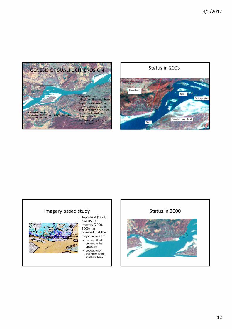
GENESIS OF SUALKUCHI EROSION
• located between two hillocks on the north bank
• As per curvature of the major channel, erosion should not have occurred in this portion of the channel reach
• But devastating Erosion has occurred
It is located between
Longitudes: 91º32‘E and 91º36‘E Latitudes:26º9‘N and 26º11‘N
Status in 2003
Eroded area
D/s
U/s
Soil deposited
Elevated river island
Imagery based study• Toposheet (1973)
and LISS-3 Imagery (2000, 2003) has revealed that the major causes are:
– natural hillock, present in the upstream
– deposition of sediment in the southern bank
Status in 2000

4/5/2012
13
Field Investigation
• Field investigation was carried out to measure the River Cross section and Flow Velocity
•GPS was used to record the location while flow meter, echo sounder and heavy weight were used for sounding.
Grid
Bathymetries
• Data collected from thesurvey carried out on 20-10-04 has been used along withthe other information forpreparing the bathymetry.
• For each cell the depthinformations are given asinput in the bathymetry fileon the basis of:– Observed depth
– General gradient (1: 10,000)
– Information from imageries
– Logical interpolation
Simulation Results
• Original condition

4/5/2012
14
Present conditionPUBLIC MEMORY
4/5/2012
15
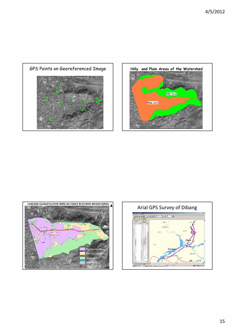
GPS Points on Georeferenced Image Hilly and Plain Areas of the Watershed
Arial GPS Survey of Dibang
Dibang
Bramaputra

4/5/2012
16
Dam break
Inundation
map
Maximum
Probable Inundation
(time=2300sec
s)
Bor gul i
Ser am
Bi j ar i
B ango
Anpum
Namsi ng
A mar apur
M er
B or l ung
P ar buk
Ji yaNogpok
Ol d A bal i
K undi l
M ani pur i Bast i
Rani
Si ka T odeng
Si l l i
Kemi
Oyr amghat
3 2 km d / s
2 8 0 5' 3 9 ' 'N
4 8 km d / s
16 km d / s
28 14 ' 18 ' ' N
2 7 56 ' 57' ' N
11 km d / s
6 3 km d / s
Ni z amghat ar ea
Bomj i r
D eopani P r ot ect ed For est
D ense M i xed For est
D ense mi xed f or est
P asi ghat T own
P ugl am
Sant i pur
Nepal i Gaon
B ur abur i D eor i Gaon
Bor pukhur i
Chapakhowa
I s l ampur
Kukur mor a
Bosagaon
Ker i m P r ot ect ed For est
Reser ved For est
N
Bang o
Related Documents


