Welcome message from author
This document is posted to help you gain knowledge. Please leave a comment to let me know what you think about it! Share it to your friends and learn new things together.
Transcript

Modern HFC Network

Forward
3

Return
4

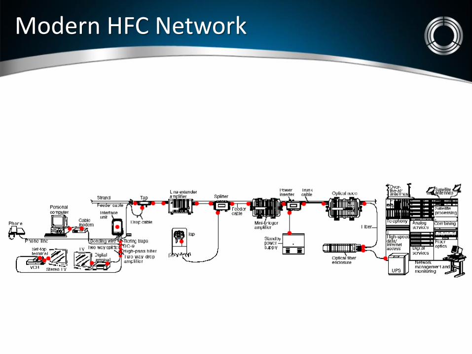
HFC Network
Cable operators use their network to provide a whole range of services to their customers: • Analogue TV services. • Digital TV services • DVR • Video-on-demand services. • High-speed data services. • Telephony services. • Commercial Services.

MoCA
Today, MoCA versions 1.0/1.1 are widely used by TV operators to offer multi-room digital video recorder (DVR) service, IP based video-on-demand (VOD) and bring broadband connectivity to set-top boxes and networked televisions. • Verizon, with its FIOS data/TV/voice service uses MoCA extensively to deliver broadband data service
and VOD. • Satellite TV operators features MoCA in its latest generation of STBs and DVRs and uses DIRECTV
Ethernet to Coax Adapters (DECA) to attach to the broadband router and move older equipment onto the network.
• Dish Networks also uses MoCA enabled STB, DVR and MoCA adapters.
• MoCA 2.0 more than doubles the available throughput of MoCA 1.1. Providing a minimum of 400 Mbps of useable MAC throughput in its baseline profile and is able to keep pace and distribute more video and even greater levels of broadband service brought about by DOCSIS 3.0 deployments.
• MoCA was designed to transport high-speed streaming video data over the existing coax cable distribution plants in homes.
• Coax cable is the ideal medium but, the challenge of sending high-speed data over coax is that the distribution is not designed for room-to-room signal flow but are designed to feed a common signal to different rooms in the house.
• The consequences of this topology are that room-to-room channel characteristics are not well controlled and may include severe multipath and high path loss.
• The MoCA system deals with these channels by using bit-loaded OFDM to adapt to each channel independently and by transmitting high signal power.
• MoCA is capable of operating on various frequencies to avoid existing signals. For example, in a home with CATV signals below 1 GHz, MoCA operates above 1125 MHz in a band called D.
NOTE: In a home with satellite, MoCA can operate between 475 and 625 MHz in a band called E.
MoCA over Coax
MoCA
Majority of service issues inside the home are caused by wiring faults. Such as QAM video tiling and distortions usually due to coax impairments and ingress As capacity is increased smaller coax impairments have greater impacts It is estimated that between 90% troubleshooting inside a home is coax path related • Replacing connectors, splitters, faulty coax, etc… • Place POE Filter at input of splitter to minimize reflections from ground block to
minimize reflection from ground block cable length
MoCA can have issues that QAM would not be affected by: • High End roll off (splitters, faulty coax, home amplifiers, water in passives) • High attenuation Wall plate to Wall plate (node-to-node) • High Frequency ingress • Ingress occurring in the higher MoCA frequency band • CPE issues • STB with a bad MoCA circuit but QAM demod is operational

• Without a MoCA filter, MoCA signals will bleed over to adjacent users and create interference.
MoCA POE

•The MoCA Ground Block contains signals within each user preventing interference
• MoCA Aqua can be used when a Ground Block is not required
MoCA POE
Customer
Unfortunately the in-house cable network is not under control of the cable operator. The customer is free to use any type of connector, cable and other devices (splitters, amplifiers,...). In many cases the quality of the installation (connector mounting, cable preparation…) is bad at best. In addition un - terminated ports on splitters are open holes, where the interfering signal can easily enter the cable network.

Customer Premises
12
Dish Direct Broadband

Customer Experience with Noise

New Noise

New Noise – LTE (4G)
Unlocking the LTE opportunity has been the re-allocation of the broadcast spectrum. The conversion of analog TV stations to digital transmission standards has freed-up portions of the UHF band enabling new cellular technologies. LTE differs from previous cellular technologies in a number of ways, primarily in terms of frequency allocations, bandwidths, and modulation types. . This has important ramifications for operators of CATV networks with regards to the possibility of both ingress and egress interference. Reports of both types of interference have already been received from both cellular carriers as well as MSOs. The number and severity of these incidents is expected to increase as LTE becomes more widely deployed.
Why Is LTE Different
While LTE deployments are currently in the UHF bands, plans have been proposed for using additional spectrum, which is lower in frequency, will be used to make room for new cellular services. Although it is impossible to predict, it is likely to assume that a significant part of this spectrum will be at lower frequencies, even as low as 500 Mhz. Propagation and attenuation characteristics of UHF signals are very different from signals at lower frequencies : lower frequency signals tend to travel further and be less strongly attenuated by structures, etc. than higher frequency signals. An understanding of LTE technology and the means by which LTE-related interference can be identified, localized, and resolved is critical for the efficient operation of both cellular and CATV networks.
Additional Testing
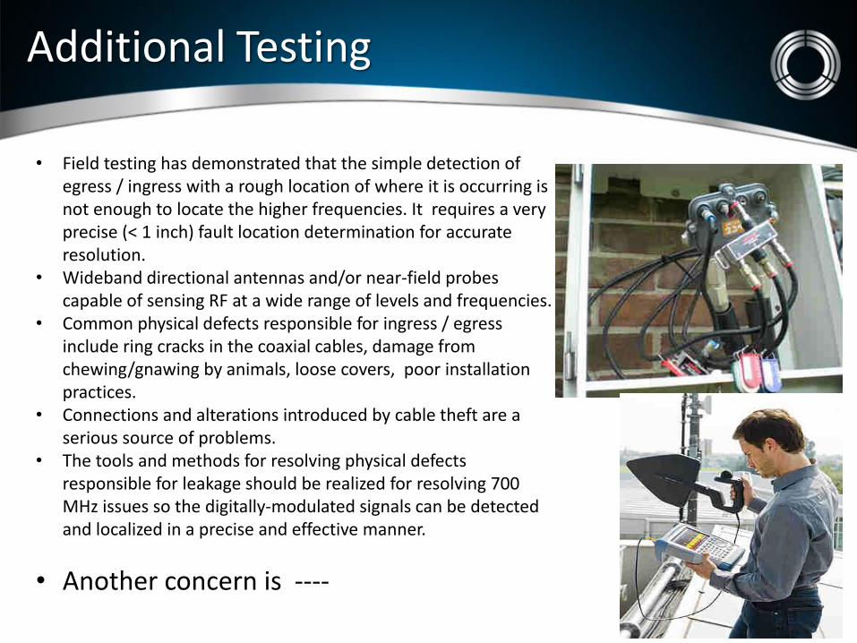
• Field testing has demonstrated that the simple detection of egress / ingress with a rough location of where it is occurring is not enough to locate the higher frequencies. It requires a very precise (< 1 inch) fault location determination for accurate resolution.
• Wideband directional antennas and/or near-field probes capable of sensing RF at a wide range of levels and frequencies.
• Common physical defects responsible for ingress / egress include ring cracks in the coaxial cables, damage from chewing/gnawing by animals, loose covers, poor installation practices.
• Connections and alterations introduced by cable theft are a serious source of problems.
• The tools and methods for resolving physical defects responsible for leakage should be realized for resolving 700 MHz issues so the digitally-modulated signals can be detected and localized in a precise and effective manner.
• Another concern is ----

Bonding & Grounding
Purpose?
– Protect people... • personal injury
• loss of life
– Protect property... • live wires
• structure fire
• lightning...
- Minimize noise

Induction, Transient, Foreign Currents
Electrostatic or magnetic force from power lines...
Current surges travel along coax surface...
Any current on Coax
Source includes... – Power
– Telephone
– Lightning
– Static charge
– Cellular
– Satellite DVR (hopper)
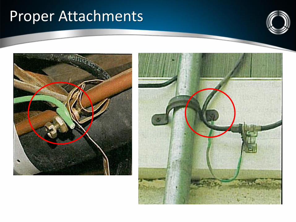
Proper Attachments

48 hrs.
336 hrs.
672 hrs.
Start With the Right Hardware
– Mechanical galvanizing means durability
Diamond Competitor
Salt Spray Testing Per ASTM
DIAMOND® HARDWARE

DIAMOND® HARDWARE

The drop

Interference
The convergence of advanced subscriber services and advancements in connector design which has defined a new category of connector – the Continuity Connector. With the majority of f‐connectors residing within a subscriber’s premises and are beyond the control of the system operator, there is a high likelihood that connections will be disturbed or adjusted by the subscriber and virtual certainty that any given residence will have connectors which are no longer fully fastened to their respective ports.
In addition to customers modifying the initial installation, ports on the majority of customer premise equipment (CPE) cannot withstand torque in excess of 10inlb, so these connections are often intentionally left loose to avoid damage. Which Causes :
Video pixilation Tiling and stuttering Packet loss and reduced data rates Poor signal‐to‐noise performance
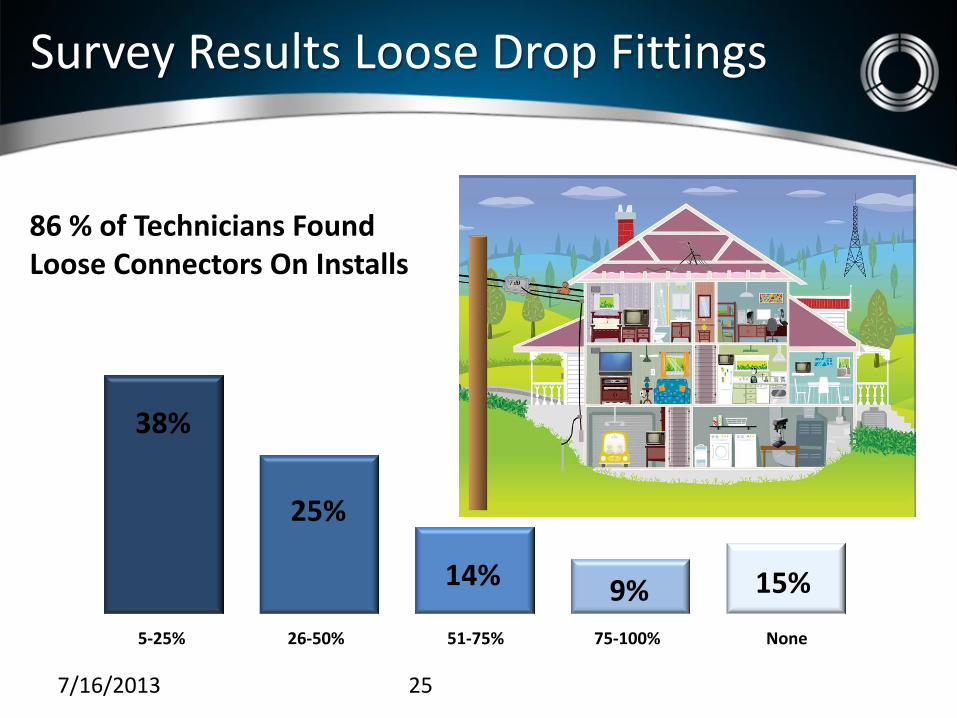
Survey Results Loose Drop Fittings
7/16/2013 25
38%
14% 9% 15%
5-25% of the time
26-50% of the time
51-75% of the time
75-100% of the time
None of the time
25%
89% of TWC Carolinas Technicians Found Loose Connectors On Installs
86 % of Technicians Found Loose Connectors On Installs

Loose connectors
• The problem of loose connectors arises from the traditionally simplistic design of an f‐connector. As a cost‐effective and mechanically robust feed‐through, the connection has only one moving part, the nut, which spins freely around the post.
• When properly installed, the post which is permanently bonded to the shield of the coaxial cable (leaving only the nut free to rotate). It is this free rotation and the clearance between nut and post necessary to enable this rotation which can lead to intermittent contact.
• This can occur even on a clean, new connector when the nut is not clamping the post firmly to the equipment port. If movement is possible in this state, a slight shifting of the equipment or cable can result in an open ground for the signal path and for the DC loop if there is power on the line. An open ground creates many undesirable electrical effects including non‐zero potential on the shield, variable loop resistance, ingress and egress of RF energy, micro‐arcing, etc... These lead, in turn, to degraded video performance and greater data congestion driven by high packet retransmission rates.
• Loose connectors inside and outside the home have been observed by many systems within the cable and satellite television industry.
• It is a common misconception that “connectors are never left loose outdoors” but the data from numerous technician surveys proves otherwise.
• While it is true that the percentage of loose connectors outdoors tends to be lower than inside the home, our findings indicate that it remains a significant problem despite the recommended practice of using a wrench outdoors.

What happens
Connector interface in tightened state Nut in contact with post
Connector interface not tight Nut not in contact with post

Measurement
In the Installed State as compared to a fully tightened connector: 1. Negligible degradation in return loss with only one thread of engagement 2. Negligible degradation in insertion loss with only one thread of engagement 3. Negligible difference in ingress with only one thread of engagement
< 0.05

Return Path before
Pre‐Study Return Path Noise Readings

Return Path after
Post‐Study Return Path Noise Readings

Signal Leakage results
Conclusion
• Our research and field testing confirms both the significant presence of loose connectors indoors and out as well as the adverse effects they have on network performance due to the variety of signal transmission impairments caused by an intermittent loss of ground.
• Continuity Connectors are a viable solution to the problem of connectors in
the loose state or otherwise loosened by subscriber tampering. • Numerous lab and field tests show conclusively that Continuity Connectors
can provide significant improvements to network performance when compared to standard connectors that are left loose to the degree that is typically found in the field.

Ingress / Egress from loose fitting
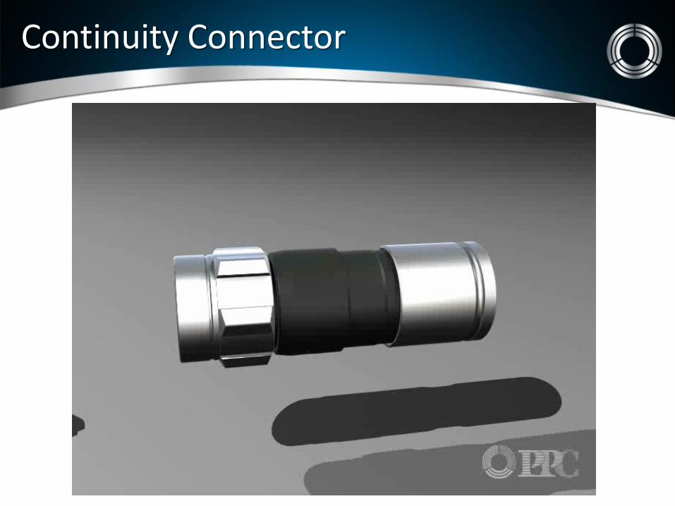
Continuity Connector

Network Conditioning

42 54 860
Reverse Forward Future
Services
-9 dB
•Provides a flat loss response across the full band
•Primary application in Headends
•Starting to be used in the drop plant
0 dB
Full Band Attenuator

42 54 860
Reverse Forward Future Services
-10 dB
•Provides an inverted response to cable loss
•Used to correct excessive cable loss at end of line
•May need drop amplifier
0 dB
Full Band Equalizer

42 54 860
Reverse Forward Future Services
-10 dB
•Equalizes the forward path only
•Corrects tilt from excessive cable loss without affecting the return
0 dB
Forward Band Equalizer

Cable Simulator
42 54 860
Reverse Forward Future
-12 dB
•Simulates drop cable loss with slope
•Opposite condition of exessive cable loss
•Usually after the distribution amplifier
0 dB
Cable Simulator

Forward Path Attenuator
42 54 860
Reverse Forward Future
-15 dB
•Provides flat loss attenuation to forward path only
•Used mostly at high value taps
•Can be used to with drop amplifiers
0 dB
Forward Path Attenuator

5
Modem Carrier STB
-12 dB
30 54 42 15 18
0 dB
Step Attenuator – Reverse Path
•Compensates for lack of return path attenuation on low value taps.
•Low value taps allow high levels of ingress to funnel back
•Modems transmit at a lower level and creates poor Signal to Noise Ratio (SNR)
•Step Attenuators reduce noise levels minimizing laser clipping
•Reduces the negative effects of micro - reflections
An all digital network doesn’t mean you should ignore analogue symptom's. CSO / CTB C/N Passive Losses Operating Levels Leakage abatement Customer meddling
Fundamental’s

Entry Series simplify installs
43
Eliminates 6 F-connectors, Amp,
2-way and 4- way splitters
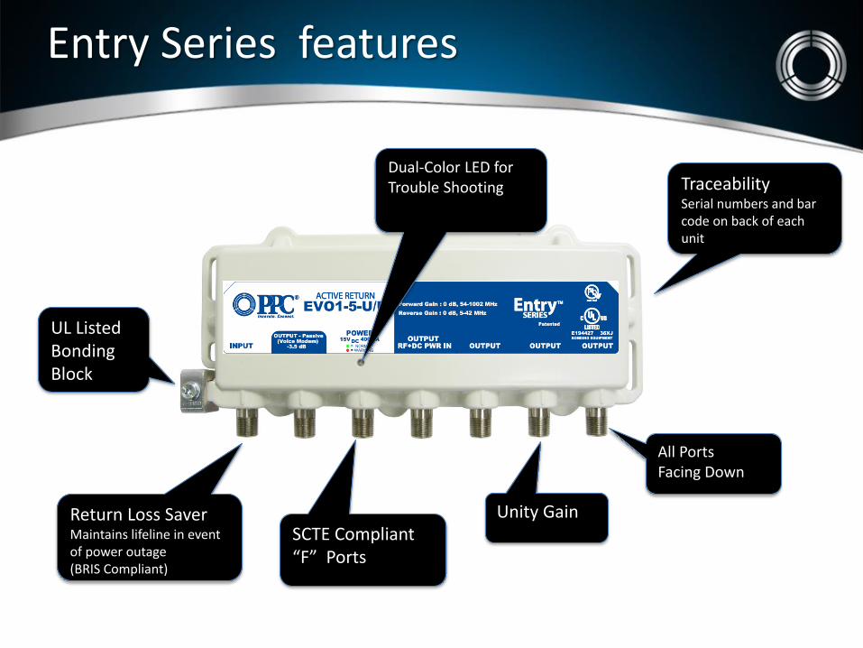
Return Loss Saver Maintains lifeline in event of power outage (BRIS Compliant)
SCTE Compliant “F” Ports
UL Listed Bonding Block
Traceability Serial numbers and bar code on back of each unit
All Ports Facing Down
Entry Series features
Feature Set
Dual-Color LED for Trouble Shooting
Unity Gain

Surge Protection -40 kV, 20 kA on Input -B3 combo wave on all RF ports
Dedicated Power Port (BRIS Compliant)
EISA Compliant Power Supplies (BRIS Compliant)
One power supply for all models 15 VDC, 400 mA
Power Supply with built-in Power Inserter (optional)
Entry Series continued
Feature Set
MoCA POE Filter Built in


Thank you for your time!!
Related Documents