© 2008 QuickL ogic Corporation www.quicklogic.com • • • • • 1 • • • • • Introduction ModelSim by Model T echnology is a popular VHDL, V erilog, and mixed VHDL/Ver ilog simulator. This Quick Note describes: • The ModelSi m flow for pre-layout and post-layout simulations when using QuickLog ic devices . • The file s neede d for VHDL and V erilo g simula tion. • How to make a macro fi le and e xecute it with the do command. For the examples provided, a simple RAM design is run through the simulation flow in ModelSim SE Plus 5.6d. Using ModelSim for Verilog Simulation Pre-Layout (Functional) Verilog Simulation Necessary Files The files required to run a function al simulation are: 1. If QuickLogic macros have been instantiated in the design, m acr os. v, m acr os- 25. v, or macr os- 35 . v is needed. They are located in the C : \ pasi c\ spde\ dat a directory. 2. Design source files, < filename>. v. 3. The test fixture file, < toplevel_file_name>. t f . Creating the Project and Running the Simulation To create a project and run the simulation: 1. Start ModelSim. QuickLogic ® Quick Note 87 Using ModelSim for Simulations with QuickLogic Devices

Welcome message from author
This document is posted to help you gain knowledge. Please leave a comment to let me know what you think about it! Share it to your friends and learn new things together.
Transcript

7/27/2019 modelsim quick note
http://slidepdf.com/reader/full/modelsim-quick-note 1/22
© 2008 QuickLogic Corporation www.quicklogic.com
•
•
•
•
•
1
• • • • •
Introduction
ModelSim by Model Technology is a popular VHDL, Verilog, and mixed VHDL/Verilog simulator. This Quick Note describes:
• The ModelSim flow for pre-layout and post-layout simulations when using QuickLogic devices.
• The files needed for VHDL and Verilog simulation.
• How to make a macro file and execute it with the do command.
For the examples provided, a simple RAM design is run through the simulation flow in ModelSim SE Plus 5.6d.
Using ModelSim for Verilog Simulation
Pre-Layout (Functional) Verilog Simulation
Necessary Files
The files required to run a functional simulation are:
1. If QuickLogic macros have been instantiated in the design, macr os. v, macr os- 25. v, ormacr os- 35. v is needed. They are located in the C: \ pasi c\ spde\ dat a directory.
2. Design source files, <filename>. v.
3. The test fixture file, <toplevel_file_name>. t f .
Creating the Project and Running the Simulation
To create a project and run the simulation:
1. Start ModelSim.
QuickLogic ®
Quick Note 87
Using ModelSim for Simulationswith QuickLogic Devices

7/27/2019 modelsim quick note
http://slidepdf.com/reader/full/modelsim-quick-note 2/22
www.quicklogic.com © 2008 QuickLogic Corporation•
•
•
•
•
•
Using ModelSim for Simulations with QuickLogic Devices Rev. B
2
2. Select File -> New -> Project.The Create Project screen is displayed.
3. Type the name of the project in the Project Name field.
4. Type the location of the project in the Project Location field.
5. Type the name of the default library in the Default Library Name field.
6. Click OK.The Add Items to the Project screen is displayed.

7/27/2019 modelsim quick note
http://slidepdf.com/reader/full/modelsim-quick-note 3/22

7/27/2019 modelsim quick note
http://slidepdf.com/reader/full/modelsim-quick-note 4/22
www.quicklogic.com © 2008 QuickLogic Corporation•
•
•
•
•
•
Using ModelSim for Simulations with QuickLogic Devices Rev. B
4
14. Select Simulate -> Simulate to simulate the design.The Simulate screen is displayed.
15. Select the Design tab.
16. Select the module name of the test fixture (from the Default Library that you specified instep 5. on page 2) in the Name field.
17. Click Load to load the simulation.

7/27/2019 modelsim quick note
http://slidepdf.com/reader/full/modelsim-quick-note 5/22
© 2008 QuickLogic Corporation www.quicklogic.com•
•
•
•
•
•
Using ModelSim for Simulations with QuickLogic Devices Rev. B
5
18. Select View -> Wave to begin adding the waveform signals.The Wave screen is displayed.
19. Select View Signals to view signals.The Signals screen is displayed.

7/27/2019 modelsim quick note
http://slidepdf.com/reader/full/modelsim-quick-note 6/22
www.quicklogic.com © 2008 QuickLogic Corporation•
•
•
•
•
•
Using ModelSim for Simulations with QuickLogic Devices Rev. B
6
20. Select View -> Structure to view the hierarchy of the design and see the internal signals within the regionselected in the main window.The Structure screen is displayed.
21. In the Signals screen, select Add -> Wave -> Signals in Design to add the waveform signals to thewaveform viewer. You can also drag and drop the signals from the Signals screen onto the waveformviewer screen.

7/27/2019 modelsim quick note
http://slidepdf.com/reader/full/modelsim-quick-note 7/22
© 2008 QuickLogic Corporation www.quicklogic.com•
•
•
•
•
•
Using ModelSim for Simulations with QuickLogic Devices Rev. B
7
22. In the waveform viewer, click the Run - All icon to run the simulation.
23. To make this process easier, all these commands can be entered in a macro file (. do) and run in a singlestep. This is shown later in the Quick Note.
Post-Layout (Timing) Verilog Simulation
Necessary Files
The files required to run a timing simulation are:
1. QuickLogic primitive file: ql pr i m. v which describes the functionality of primitive components specified
in the . vq file.
2. Back Annotated verilog netlist, <toplevel_file_name>. vq file that is generated during Back Annotation run on SpDE.
3. Back Annotated timing file, <toplevel_file_name>. sdf that is generated during Back Annotationrun on SpDE.
4. The test fixture file, <toplevel_file_name>. t f .
NOTE: For Back Annotation in SpDE, select Tools->Options->Back Annotation and select Verilog fromthe list of simulators.
Run - All
7/27/2019 modelsim quick note
http://slidepdf.com/reader/full/modelsim-quick-note 8/22
www.quicklogic.com © 2008 QuickLogic Corporation•
•
•
•
•
•
Using ModelSim for Simulations with QuickLogic Devices Rev. B
8
Creating the Project and Running the Simulation
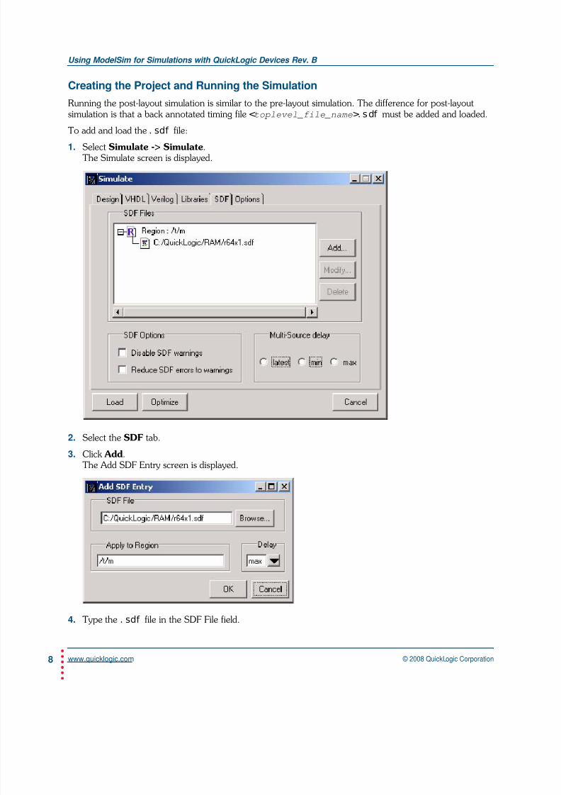
Running the post-layout simulation is similar to the pre-layout simulation. The difference for post-layoutsimulation is that a back annotated timing file <toplevel_file_name>. sdf must be added and loaded.
To add and load the . sdf file:
1. Select Simulate -> Simulate.The Simulate screen is displayed.
2. Select the SDF tab.
3. Click Add.The Add SDF Entry screen is displayed.
4. Type the . sdf file in the SDF File field.

7/27/2019 modelsim quick note
http://slidepdf.com/reader/full/modelsim-quick-note 9/22
© 2008 QuickLogic Corporation www.quicklogic.com•
•
•
•
•
•
Using ModelSim for Simulations with QuickLogic Devices Rev. B
9
5. Type the region it will apply to in the Apply to Region field.For example:
/t/m where: t is the module name and m is the instance name.
6. Select the type of delay (min., typ. and max.) from the Delay pull-down menu.
7. Click OK.
8. In the Simulate screen, select the Design tab.The Design screen is displayed.
9. Select the module name of the test fixture in the Name field.
10. Click Load to load the simulation.
The reset of the process is the same as described in “Pre-Layout (Functional) Verilog Simulation” on page 1.

7/27/2019 modelsim quick note
http://slidepdf.com/reader/full/modelsim-quick-note 10/22
www.quicklogic.com © 2008 QuickLogic Corporation•
•
•
•
•
•
Using ModelSim for Simulations with QuickLogic Devices Rev. B
10
Using ModelSim for VHDL Simulation
Pre-Layout (Functional) VHDL Simulation
Necessary Files
The files required to run a functional simulation:
1. If QuickLogic macros have been instantiated in the design, the macr os. vhd, macr os- 25. vhd ormacr os- 35. vhd file is needed. They are located in C: \ pasi c\ spde\ data directory.
2. Design source files, <filename>. vhd.
3. The test bench file, <toplevel_file_name_tb>. vhd.
Creating the Project and Running the Simulation
To create a project and run the simulation:
1. Start ModelSim.
2. Select File -> New -> Project.The Create Project screen is displayed.
3. Type the name of the project in the Project Name field.
4. Type the location of the project in the Project Location field.
5. Type the name of the default library in the Default Library Name field.

7/27/2019 modelsim quick note
http://slidepdf.com/reader/full/modelsim-quick-note 11/22
© 2008 QuickLogic Corporation www.quicklogic.com•
•
•
•
•
•
Using ModelSim for Simulations with QuickLogic Devices Rev. B
11
6. Click OK.The Add Items to the Project screen is displayed.
7. Click on the Add Existing File icon.The Add File to Project screen is displayed.
8. Browse to select the file in the File Name field.
9. Select VHDL from the pull-down menu in the Add file as type field.
10. Click OK.Repeat step 8. on page 11 through step 10. on page 11 for each file to be added.
11. Select Compile -> Compile Order to set the compile order.Always have macr os. vhd as the first file in the compile order and the test bench as the last file to becompiled. For example:
macr os. vhd
r am64x18. vhd
r 64x1. vhd
r 64x1. t b.
12. Click OK.
7/27/2019 modelsim quick note
http://slidepdf.com/reader/full/modelsim-quick-note 12/22
www.quicklogic.com © 2008 QuickLogic Corporation•
•
•
•
•
•
Using ModelSim for Simulations with QuickLogic Devices Rev. B
12
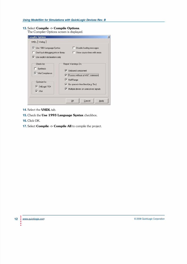
13. Select Compile -> Compile Options.The Compiler Options screen is displayed.
14. Select the VHDL tab.
15. Check the Use 1993 Language Syntax checkbox.
16. Click OK.
17. Select Compile -> Compile All to compile the project.

7/27/2019 modelsim quick note
http://slidepdf.com/reader/full/modelsim-quick-note 13/22
© 2008 QuickLogic Corporation www.quicklogic.com•
•
•
•
•
•
Using ModelSim for Simulations with QuickLogic Devices Rev. B
13
18. Select Simulate -> Simulate to simulate the design.The Simulate screen is displayed.
19. Select the Design tab.
20. Select the module name of the test fixture (from the Default Library that you specified instep 5. on page 10) in the Name field.
21. Click Load to load the simulation.

7/27/2019 modelsim quick note
http://slidepdf.com/reader/full/modelsim-quick-note 14/22
www.quicklogic.com © 2008 QuickLogic Corporation•
•
•
•
•
•
Using ModelSim for Simulations with QuickLogic Devices Rev. B
14
22. Select View -> Wave to begin adding the waveform signals.The Wave screen is displayed.
23. Select View Signals to view signals.The Signals screen is displayed.
7/27/2019 modelsim quick note
http://slidepdf.com/reader/full/modelsim-quick-note 15/22
© 2008 QuickLogic Corporation www.quicklogic.com•
•
•
•
•
•
Using ModelSim for Simulations with QuickLogic Devices Rev. B
15
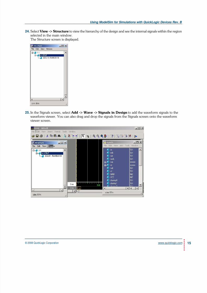
24. Select View -> Structure to view the hierarchy of the design and see the internal signals within the regionselected in the main window.The Structure screen is displayed.
25. In the Signals screen, select Add -> Wave -> Signals in Design to add the waveform signals to thewaveform viewer. You can also drag and drop the signals from the Signals screen onto the waveformviewer screen.

7/27/2019 modelsim quick note
http://slidepdf.com/reader/full/modelsim-quick-note 16/22
www.quicklogic.com © 2008 QuickLogic Corporation•
•
•
•
•
•
Using ModelSim for Simulations with QuickLogic Devices Rev. B
16
26. In the waveform viewer, click the Run - All icon to run the simulation.
To make this process easier, all these commands can be entered in a macro file (. do) and run in a single step.This is shown later in the Quick Note.
Post-Layout (Timing) VHDL Simulation
Necessary Files
The files required to run a timing simulation:
1. QuickLogic primitive file, ql vt l 95. vhd which describes the functionality of primitive components
specified in the . vhq file.
2. Back Annotated vhdl netlist, <toplevel_file_name>. vhq file that is generated during Back Annotation run on SpDE.
3. Back Annotated timing file, <toplevel_file_name>. sdf that is generated during Back Annotationrun on SpDE.
4. The test bench file, <toplevel_file_name>. t b.
NOTE: For Back Annotation in SpDE, Select Tools -> Options -> Back Annotation and select ModeltechVital 3.0 from the list of simulators.
Creating the Project and Running the Simulation
Running the post-layout simulation is similar to the pre-layout simulation. The difference for post-layoutsimulation is:
• A back-annotated timing file <toplevel_file_name>. sdf must be added and loaded.
• ql vt 195. vhd must be compiled in within the ql pr i ms library.
Run - All

7/27/2019 modelsim quick note
http://slidepdf.com/reader/full/modelsim-quick-note 17/22
© 2008 QuickLogic Corporation www.quicklogic.com•
•
•
•
•
•
Using ModelSim for Simulations with QuickLogic Devices Rev. B
17
To add and load the . sdf file:
1. Select Simulate -> Simulate.The Simulate screen is displayed.
2. Select the SDF tab.
3. Click Add.
The Add SDF Entry screen is displayed.
4. Type the . sdf file in the SDF File field.

7/27/2019 modelsim quick note
http://slidepdf.com/reader/full/modelsim-quick-note 18/22
www.quicklogic.com © 2008 QuickLogic Corporation•
•
•
•
•
•
Using ModelSim for Simulations with QuickLogic Devices Rev. B
18
5. Type the region it will apply to in the Apply to Region field.For example:
/t/m where: t is the module name and m is the instance name.
6. Select the type of delay (min., typ. and max.) from the Delay pull-down menu.
7. Click OK.
8. In the Simulate screen, select the Design tab.The Design screen is displayed.
9. Select the module name of the test fixture in the Name field.
10. Click Load to load the simulation.
7/27/2019 modelsim quick note
http://slidepdf.com/reader/full/modelsim-quick-note 19/22
© 2008 QuickLogic Corporation www.quicklogic.com•
•
•
•
•
•
Using ModelSim for Simulations with QuickLogic Devices Rev. B
19
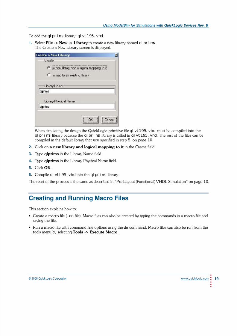
To add the ql pr i ms library, ql vt 195. vhd:
1. Select File -> New -> Library to create a new library named ql pr i ms.The Create a New Library screen is displayed.
When simulating the design the QuickLogic primitive file ql vt 195. vhd must be compiled into theql pr i ms library because the ql pr i ms library is called in ql vt 195. vhd. The rest of the files can becompiled in the default library that you specified in step 5. on page 10.
2. Click on a new library and logical mapping to it in the Create field.
3. Type qlprims in the Library Name field.
4. Type qlprims in the Library Physical Name field.
5. Click OK.
6. Compile ql vt l 95. vhd into the ql pr i ms library.The reset of the process is the same as described in “Pre-Layout (Functional) VHDL Simulation” on page 10.
Creating and Running Macro Files
This section explains how to:
• Create a macro file (. do file). Macro files can also be created by typing the commands in a macro file andsaving the file.
• Run a macro file with command line options using the do command. Macro files can also be run from thetools menu by selecting Tools -> Execute Macro.

7/27/2019 modelsim quick note
http://slidepdf.com/reader/full/modelsim-quick-note 20/22
www.quicklogic.com © 2008 QuickLogic Corporation•
•
•
•
•
•
Using ModelSim for Simulations with QuickLogic Devices Rev. B
20
To create a macro file:
1. Create a . do file.Continuing with the simple RAM design example in the previous section, create a . do file using thefollowing macro as an example:
# before running this script change the current directory# in ModelSim to access the simulation files by using the cd command
cd c:/current_working_directory
# create work library
vlib work
# compile design files
vlog -work work macros.v
vlog -work work ram64x18.v
vlog -work work r64x1.v
# compile test bench files
vlog -work work r64x1.tf
# start simulation
vsim -t 100ps work.t
# open a waveform window
view wave
# add signals
add wave /t/i
add wave /t/wclk
add wave /t/rclkadd wave /t/we
add wave /t/re
add wave /t/wa(5:0)
add wave /t/ra(5:0)
add wave /t/wd
add wave /t/rd
# run simulation
run -all
2. Save as <filename>. do.

7/27/2019 modelsim quick note
http://slidepdf.com/reader/full/modelsim-quick-note 21/22
© 2008 QuickLogic Corporation www.quicklogic.com•
•
•
•
•
•
Using ModelSim for Simulations with QuickLogic Devices Rev. B
21
To run a macro file:
All the commands run from the command line window and can be written to a specified file. The resulting filecan be run using the do command.
1. The syntax for writing a transcript file is:
wr i t e t r anscr i pt [ <filename>]
2. The do command executes commands contained in a macro file. The syntax for the do command is:
do <filename>
ModelSim Support Information
• ModelSim includes help files and tutorials that describe features and instructions for use.
• To contact ModelSim Support: http://www.model.com/support/default.asp
Contact Information
Phone: (408) 990-4000 (US)
(905) 940-4149 (Canada)
+(44) 1932-57-9011 (Europe)
+(852) 2567-5441 (Asia)
E-mail: [email protected]
Sales: [email protected]
Support:www.quicklogic.com/support
Internet: www.quicklogic.com
Revision History
Revision Date Originator and Comments
A April 2003Mehul Kochar and Kathleen Murchek
First release.
B November 2008
Kathleen Murchek
Updated banner, contact info, and copyright info.
Added disclaimer.

7/27/2019 modelsim quick note
http://slidepdf.com/reader/full/modelsim-quick-note 22/22
www.quicklogic.com © 2008 QuickLogic Corporation•
•
•
•
•
Using ModelSim for Simulations with QuickLogic Devices Rev. B
22
Notice of Disclaimer
QuickLogic is providing this design, product or intellectual property "as is." By providing the design, product or intellectual property as
one possible implementation of your desired system-level feature, application, or standard, QuickLogic makes no representation that this
implementation is free from any claims of infringement and any implied warranties of merchantability or fitness for a particular purpose.You are responsible for obtaining any rights you may require for your system implementation. QuickLogic shall not be liable for any
damages arising out of or in connection with the use of the design, product or intellectual property including liability for lost profit, business
interruption, or any other damages whatsoever. QuickLogic products are not designed for use in life-support equipment or applications
that would cause a life-threatening situation if any such products failed. Do not use QuickLogic products in these types of equipment or
applications.
QuickLogic does not assume any liability for errors which may appear in this document. However, QuickLogic attempts to notify
customers of such errors. QuickLogic retains the right to make changes to either the documentation, specification, or product without
notice. Verify with QuickLogic that you have the latest specifications before finalizing a product design.
Copyright and Trademark Information
Copyright © 2008 QuickLogic Corporation. All Rights Reserved.The information contained in this document is protected by copyright. All rights are reserved by QuickLogic Corporation. QuickLogic
Corporation reserves the right to modify this document without any obligation to notify any person or entity of such revision. Copying,
duplicating, selling, or otherwise distributing any part of this product without the prior written consent of an authorized representative of
QuickLogic is prohibited.
QuickLogic, pASIC, and QuickWorks are registered trademarks, and QuickLogic logo is a trademark of QuickLogic. Other trademarks
are the property of their respective companies.
Related Documents


