Models: G, GC & GM Series (25,000 BTU/HR Open Top Burners) These instructions should be read thoroughly before attempting installation. Set up and installation should be performed by qualified installation personnel. Keep area around appliances free and clear from combustibles. PLEASE RETAIN THIS MANUAL FOR FUTURE REFERENCE.

Welcome message from author
This document is posted to help you gain knowledge. Please leave a comment to let me know what you think about it! Share it to your friends and learn new things together.
Transcript

Models: G, GC & GM Series
(25,000 BTU/HR Open Top Burners)
These instructions should be read thoroughly before attempting installation. Set up and installation should be performed by qualified installation
personnel.
Keep area around appliances free and clear from combustibles.
PLEASE RETAIN THIS MANUAL FOR FUTURE
REFERENCE.

CONTENTS INSTALLATION 1 MAINTENANCE 10
OPERATION 8 SERVICE 13 RENEWAL PARTS 21
IMPORTANT
FOR YOUR SAFETY
Do not store or use gasoline or other flammable vapors and liquids in the vicinity of this or any other appliance
INSTRUCTIONS TO BE FOLLOWED IN THE EVENT THE USER SMELLS GAS MUST BE POSTED IN A
PROMINENT LOCATION THIS INFORMATION MAY BE OBTAINED BY CONSULTING THE LOCAL GAS
SUPPLIER
The information contained in this manual is important for the proper installation, use, and maintenance of this broiler Adherence to prescribed procedures and instructions will result in satisfactory operation and trouble-free service Please read this manual carefully and retain it for future reference
SHIPPING DAMAGE CLAIM PROCEDURE
For your protection, please note that equipment in this shipment was carefully inspected and packed by skilled personnel before leaving the factory The transportation company assumed full responsibility for safe delivery upon acceptance of this shipment
If shipment arrives damaged:
1 VISIBLE LOSS OR DAMAGE - Be certain this is noted on freight bill or express receipt, and signed by person making delivery
2 FILE CLAIM FOR DAMAGES IMMEDIATELY - Regardless of extent of damage
3 CONCEALED LOSS OR DAMAGE - If damage is unnoticed until merchandise is unpacked, notify transportation company or carrier immediately, and file a "concealed damage" claim with them This should be done within fifteen (15) days of date delivery is made to you Be sure to retain container for inspection
We cannot assume responsibility for damage or loss incurred in transit We will, however, be glad to furnish you with necessary documents to support your claim
INSTALLATION
The Montague Grizzly gas oven ranges are manufactured for use with the type of gas indicated on the nameplate.
The Montague Grizzly gas convection oven type ranges are produced with the best possible material and workmanship. PROPER INSTALLATION IS ESSENTIAL FOR SAFE AND EFFICIENT TROUBLE-FREE OPERATION.
THE INSTALLATION INSTRUCTIONS CONTAINED HEREIN ARE FOR THE USE OF QUALIFIED INSTALLATION AND SERVICE PERSONNEL ONLY. INSTALLATION OR SERVICE BY OTHER THAN QUALIFIED PERSONNEL MAY RESULT IN DAMAGE TO THE OVEN AND/OR INJURY TO THE OPERATOR.
Qualified installation personnel are individuals, a firm, corporation or company which either in person, or through a representative are engaged in, and are responsible for:
A. The installation or replacement of gas piping or the connection, installation, repair or servicing of equipment, who is experienced in such work, familiar with all precautions required, and has complied with all requirements of state or local authorities having jurisdiction. Reference: National Fuel Gas Code Z223.1, Section 1.4.
B. The installation of electrical wiring from the electric meter, main control box or service outlet to the electric appliance. Qualified installation personnel must be experienced in such work, be familiar with all precautions required and have complied with all requirements of state and local authorities having jurisdiction. Reference: National Electric Code, NFPA No. 70.
READ CAREFULLY AND FOLLOW THESE INSTRUCTIONS
THE RANGE(S) MUST BE INSTALLED IN ACCORDANCE WITH LOCAL CODES, OR IN THE ABSENCE OF LOCAL CODES, WITH THE NATIONAL FUEL GAS CODE, ANSI Z223.1, NATURAL GAS INSTALLATION CODE, CAN/CGA-B149.1, OR THE PROPANE INSTALLATION CODE, CAN/CGA-B149.2, AS APPLICABLE, INCLUDING:
1. The appliance and its individual shutoff valve must be disconnected from the gas supply piping system during any pressure testing of that system at test pressures in excess of 1/2 psig. (3.45 kPa).
2. The appliance must be isolated from the gas supply piping system by closing its individual manual shutoff valve during any pressure testing of the gas supply piping system at test pressure equal to or less than 1/2 psig. (3.45 kPa).
1

INSTALLATION
PROVISIONS MUST BE MADE FOR ADEQUATE AIR SUPPLY TO THE UNIT.
THE UNIT, WHEN INSTALLED, MUST BE ELECTRICALLY GROUNDED IN ACCORDANCE WITH LOCAL CODES, OR IN ABSENCE OF LOCAL CODES, WITH THE NATIONAL ELECTRICAL CODE, ANSI/NFPA 70, OR THE CANADIAN ELECTRICAL CODE, CSA C22.2, AS APPLICABLE.
Ventilating Hood
The range(s) must be installed under a properly designed ventilating hood. The hood should extend at least 6" beyond all sides of the unit. The hood should be connected to an adequate mechanical exhaust system.
Information on the construction and installation of ventilating hoods may be obtained from the 'Standard for the Installation of Equipment for the Removal of Smoke and Grease Laden Vapors from Commercial Cooking Equipment", NFPA 96, available from the National Fire Protection association. Batterymarch Park, Quincy, MA 02269.
It is also necessary that sufficient room air ingress be allowed to compensate for the amount of air removed by the ventilating system. Otherwise, a subnormal atmospheric pressure will occur which may interfere with burner performance or may extinguish the pilot flame. In case of unsatisfactory range performance, check with the exhaust fan in the "OFF" position.
Clearances
Adequate clearance must be provided at the side, back and in the aisle to allow the doors to open sufficiently to permit the removal of the racks and for serviceability. Adequate clearance for air openings into the combustion chamber must be provided.
Back: Left & Right Side:
CLEARANCES COMBUSTIBLE
CONSTRUCTION
2" (5.1cm) 11 "(27.9cm)
NONCOMBUSTIBLE
CONSTRUCTION
2" (5.1cm) 2" (5.1cm)
6" (15.2cm) HIGH LEGS: SUITABLE FOR INSTALLATION ON COMBUSTIBLE FLOORS. WITHOUT LEGS: FOR USE ONLY ON NONCOMBUSTIBLE FLOORS.
CAUTION DO NOT OBSTRUCT THE FLOW OF COMBUSTION AND VENTILATION AIR. KEEP THE APPLIANCE AREA FREE AND CLEAR FROM COMBUSTIBLES.
2

INSTALLATION
ASSEMBLY
DO NOT LIFT RANGE BY THE FRONT RAIL.
Uncrate range as near to final location as possible. Remove all shipping wire from burners and all packing material and accessories from oven interior.
IF RANGE IS EQUIPPED WITH A FRYTOP SECTION, REMOVE WOOD SHIPPING STRIPS LOCATED BELOW THE GREASE TROUGH.
Then assemble as follows:
Floor Mounted Range:
1. Screw the adjustable feet of the legs in all the way. Then tightly screw the complete leg assembly into mounting holes at each corner of the range. If the unit is intended for curb installation, no legs are provided. The curb must be noncombustible material.
2. Install door handle and secure with screws that are provided. See diagram for correct orientation.
3. Lift high shelf above the range and slide channels into position. Secure to range back with screws that are provided.
3

INSTALLATION
Cabinet or Skeleton Ranges: Follow above instructions.
Modular Ranges: Assemble modular base and set in place. Adjust feet as explained above.
Counter Ranges: Set unit in desired position and secure to counter using holes provided at rear and bracket at front.
All Ranges: 1. Install Open Top and Hot Top sections as shown in diagram
below. Install burner bowls and grates on Open Top section.
2. Install top burner valve handles and thermostat knob(s). If top burner valve handles fit loose on valve shaft, spread slot on end of shaft slightly with screwdriver blade so that handle will fit snug.
3. When range is in permanent position, level unit by placing carpenter's level on oven bottom and level from front to back and side to side.
Adjust as follows:
FLOOR INSTALLATION ON LEGS: Adjust by turning the foot of the adjustable leg. Make sure the leg does not turn.
COUNTER OR CURB INSTALLATION: Level range from front to rear and side to side using a carpenter's level. Place shim under low side.
4

INSTALLATION
Fry Top Ranges:
Leveling bolts are at the rear of the range under the Fry Top plate. Adjust leveling bolts so that the plate is pitched to the front to provide for grease runoff. Be sure wooden strips have been removed from below the grease trough.
GAS PRESSURE REGULATOR
THIS RANGE IS DESIGNED FOR USE WITH A GAS PRESSURE REGULATOR. THE REGULATOR SUPPLIED WITH THIS UNIT MUST BE USED.
FOR NATURAL GAS: This gas pressure regulator is factory adjusted for 6.0" W.C. manifold pressure. The rated inlet pressure to the regulator is 1/2 psig (3.45kPa).
FOR PROPANE GAS: This gas pressure regulator is factory adjusted for 10.0" W.C. manifold pressure. The rated inlet pressure to the regulator is 1/2 psig (3.45kPa).
Unless otherwise specified, the range is equipped with fixed orifices for use with a manifold pressure of 6.0" water column for natural gas and 10.0" water column for propane gas.
GAS CONNECTION
Before connecting the range to the gas supply line, be sure that all new piping has been cleaned and purged to prevent any foreign matter from being carried into the controls by the gas. In some cases, filters or drops are recommended. A separate Gas Shut Off Valve must be installed upstream from the gas pressure regulator adjacent to the range and be located in an accessible area.
It is important that adequately sized piping be run directly to the point of connection at the range, with as few elbows and tees as possible. Consult local gas company for proper piping size and gas pressure.
5

INSTALLATION
PIPE JOINT COMPOUND OR THREAD SEALANT THAT IS USED SHOULD BE RESISTANT TO ACTION OF LIQUEFIED PETROLEUM GASES.
Install the gas pressure regulator with gas flowing as indicated by the arrow on the regulator. Use pipe compound or thread sealant and carefully thread regulator to pipe so that there is no cross threading, etc., which could cause leakage.
Apply wrench only to the flat areas around the pipe tapping at the end being threaded to the pipe to avoid possible damage to the regulator body which could result in leakage.
Connect the gas supply line from the Service Gas Shut Off valve to the inlet side of the gas pressure regulator using 3/4" pipe. If flexible or semi-flexible connectors are used, an AGA listed flexible connector with an I.D. equal to 3/4" pipe must be used. DO NOT USE A DOMESTIC APPLIANCE TYPE GAS FLEXIBLE CONNECTOR. Avoid kinks or sharp bends that could restrict gas flow.
Turn Gas Shut Off Valve "ON" and immediately check carefully for gas leaks. Do this before attempting to operate the range.
TEST ALL PIPE JOINTS FOR LEAKS BEFORE OPERATING RANGE. THIS INCLUDES ALL GAS CONNECTIONS THAT MAY HAVE LOOSENED DURING SHIPMENT. USE A RICH SOAP SOLUTION (OR OTHER ACCEPTED LEAK TESTER) AROUND ALL PIPE CONNECTIONS AND ALL OTHER JOINTS. DO NOT USE AN OPEN FLAME. ABSOLUTELY NO LEAKAGE SHOULD OCCUR, OTHERWISE THERE IS A DANGER OF FIRE OR EXPLOSION DEPENDING UPON CONDITIONS. NEVER USE IF LEAKAGE IS DETECTED.
6
INSTALLATION
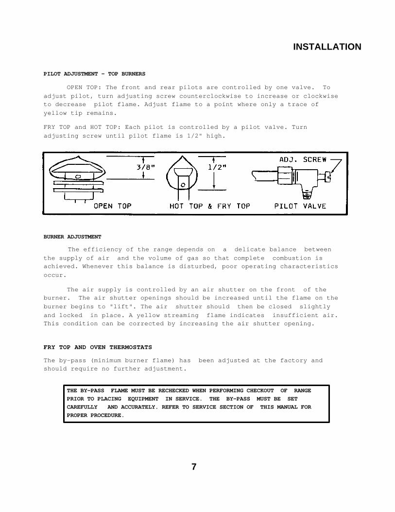
PILOT ADJUSTMENT - TOP BURNERS
OPEN TOP: The front and rear pilots are controlled by one valve. To adjust pilot, turn adjusting screw counterclockwise to increase or clockwise to decrease pilot flame. Adjust flame to a point where only a trace of yellow tip remains.
FRY TOP and HOT TOP: Each pilot is controlled by a pilot valve. Turn adjusting screw until pilot flame is 1/2" high.
BURNER ADJUSTMENT
The efficiency of the range depends on a delicate balance between the supply of air and the volume of gas so that complete combustion is achieved. Whenever this balance is disturbed, poor operating characteristics occur.
The air supply is controlled by an air shutter on the front of the burner. The air shutter openings should be increased until the flame on the burner begins to "lift". The air shutter should then be closed slightly and locked in place. A yellow streaming flame indicates insufficient air. This condition can be corrected by increasing the air shutter opening.
FRY TOP AND OVEN THERMOSTATS
The by-pass (minimum burner flame) has been adjusted at the factory and should require no further adjustment.
THE BY-PASS FLAME MUST BE RECHECKED WHEN PERFORMING CHECKOUT OF RANGE PRIOR TO PLACING EQUIPMENT IN SERVICE. THE BY-PASS MUST BE SET CAREFULLY AND ACCURATELY. REFER TO SERVICE SECTION OF THIS MANUAL FOR PROPER PROCEDURE.
7

OPERATION
OPERATING INFORMATION FOR THE RANGE HAS BEEN PREPARED FOR USE BY QUALIFIED AND/OR PROFESSIONAL OPERATING
PERSONNEL.
CAUTION DO NOT OBSTRUCT THE FLOW OF COMBUSTION AND VENTILATION AIR. KEEP THE
APPLIANCE AREA FREE AND CLEAR FROM COMBUSTIBLES.
IN THE EVENT A GAS ODOR IS DETECTED, SHUT DOWN UNITS AT MAIN SHUT OFF VALVE AND CONTACT THE LOCAL GAS COMPANY OR GAS
SUPPLIER FOR SERVICE.
GAS CONTROLS
Top Burners—Open Top, Hot Top and Manual Fry Top Check that pilots are burning. Then rotate valve handles counterclockwise to full on, burner will ignite automatically. Adjust flame height as desired. To shut down, rotate valve handle clockwise to "OFF" Position. Fry Top—Thermostat Controlled Check that pilot(s) are burning. Then push thermostat dial inward and rotate dial counterclockwise to maximum thermostat setting, bumer(s) will ignite automatically. After ignition turn thermostat dial to desired setting. To shut down, rotate thermostat dial clockwise to "OFF" Position.
OVEN A. Lighting
Turn thermostat knob to "OFF" position and wait five (5) minutes.
1. Remove burner compartment cover and open pilot access door.
2. Locate the Piezo Igniter in front of the pilot access door.
3. Press and hold red button in (Safety Pilot Valve) and repeatedly depress the button on the Piezo Igniter until the pilot burner ignites.
4. After pilot burner ignites, continue to hold red button depressed for 30 to 45 seconds or until pilot remains burning when button is released. If pilot goes out, repeat process.
5. If the pilot burner is unable to be lit with the piezo igniter, apply a lighted match to the pilot burner.
6. Close pilot access door and replace burner access panel.
8
OPERATION
7. Push thermostat dial inward and rotate dial counterclockwise to desired temperature setting.
8. IN THE EVENT OF PILOT FAILURE, ROTATE THERMOSTAT DIAL CLOCKWISE TO "OFF" POSITION AND WAIT FIVE (5) MINUTES FOR UNBURNED GAS TO ESCAPE FROM RANGE.
B. Shut Down
Rotate thermostat dial clockwise to "OFF" position.
Oven Operation
1. Turn thermostat dial to desired temperature.
2. Limit preheat time to 10-20 minutes.
3. Place food in oven. Make sure pans do not touch each other, or the oven walls.
4. Do not cover racks with aluminum foil.
5. Load and unload quickly. Avoid frequent opening of doors.
6. Turn off when not in use.
SUGGESTIONS
* There is no need to preheat an Open Top burner. Use full flame to start foods cooking quickly; reduce flame to simmer foods. Regulate the burner so that flame tips Just touch the bottom of the utensil. Use lids on pots to keep heat in. Turn burner off when not in use.
* Preheat Fry Top 10-15 minutes prior to use. Usually, a medium to low flame is adequate for light frying. If Fry Top has a thermostat, use it to avoid wasting gas and for best results. During slack periods, turn the burner down.
9

MAINTENANCE
CARE AND CLEANING
The complete range should be given a periodic general cleaning. Lint and grease suspended in the air tend to collect in air passages. Therefore, all flueways, air passages and openings, burner ports, primary air openings, etc., should be periodically cleaned to prevent clogging.
EXTERIOR
PAINTED SURFACE: Allow equipment to cool after use and wash with a mild detergent or soap solution. Dry thoroughly with a clean cloth.
STAINLESS STEEL SURFACE: To remove normal dirt, grease, or product residue from stainless steel, use ordinary soap and water (with or without detergent) applied with a sponge or cloth. Dry thoroughly with a clean cloth.
To remove grease and food splatter, or condensed vapors that have baked on the equipment, apply cleanser to a damp cloth or sponge and rub cleanser on the metal in the direction of the polished lines on the metal. Rubbing cleanser as gently as possible in the direction of the polished lines will not mar the finish of the stainless steel. NEVER RUB WITH A CIRCULAR MOTION . Soil and burnt deposits which do not respond to the above procedure can usually be removed by rubbing the surface with SCOTCH-BRITE scouring pads or STAINLESS scouring pads. DO NOT USE ORDINARY STEEL WOOL as any particles left on the surface will rust and further spoil the appearance of the finish. NEVER USE A WIRE BRUSH, STEEL SCOURING PADS (EXCEPT STAINLESS), SCRAPER, FILE OR OTHER STEEL TOOLS. Surfaces which are marred collect dirt more rapidly and become more difficult to clean. Marring also increases the possibility of corrosive attack.
To remove heat tint: Darkened areas sometimes appear on stainless steel surfaces where the area has been subjected to excessive heat. These darkened areas are caused by thickening of the protective surface of the stainless steel and are not harmful. Heat tint can normally be removed by the foregoing, but tint which does not respond to this procedure calls for a vigorous scouring in the direction of the polish lines, using SCOTCH-BRITE scouring pads or a STAINLESS scouring pad in combination with a powdered cleanser. Heat tint action may be lessened by not applying or by reducing heat to equipment during slack periods.
10

MAINTENANCE
OPEN TOP SECTION
DAILY: After grates and burner bowls are cooled, soak in solution of sal soda or other grease solvent. Thoroughly wash open top section with a damp cloth using a mild detergent soap. Rinse with clean, damp cloth and dry thoroughly. Remove and clean drip pan(s) under burners.
WEEKLY: Brush burner head with a stiff wire brush and clean clogged ports with a stiff wire or ice pick.
Excessive grease build up may be removed from burners by soaking in a solution of washing soda or any good grease solvent. Dry burners by inverting on oven rack in a low temperature oven.
FRY TOP SECTION
DAILY: Use flat edge of spatula or metal scraper to keep surface free of encrusted material during use, wipe frequently with heavy absorbent cloth. After griddle is cooled, polish with soft griddle stone or a good grade grill pad. DO NOT SCRATCH. The griddle may be washed with warm water and a cleanser. Water will not crack this griddle plate.
Empty grease container as often as necessary.
To oil the griddle, use a hydrogenated shortening. Never use salad oils, margarine or butter, as these shortenings cannot withstand temperatures greater than 300 degrees Fahrenheit
HOT TOP SECTION
DAILY: Wipe top with heavy burlap or steel wool. Rub briskly until clean. The Hot Top plate may be washed with warm water and a cleanser. Water will not crack this Hot Top plate.
11

MAINTENANCE
OVEN INTERIOR Aluminized Steel—Top, Sides and Back:
CAUTION Do not use wire brushes, steel wool or caustic solutions such as spray type cleaners, ammonia, lye or soda ash. Damage to the aluminum coating will result. USE ONLY CLEANERS THAT ARE RECOMMENDED FOR USE ON ALUMINUM.
Porcelain Enamel—Bottom and Door Liner:
Wipe up spillovers while oven is hot. Wait until oven is cool for complete cleaning. Spray type oven cleaners may be used. A mild abrasive nylon cleaning pad can be used for stubborn spillovers or stains. After cleaning, rinse well with 1/4 cup of vinegar to 1 quart water solution to neutralize any caustic residue of cleaning compound. Wipe dry.
12

SERVICE
WHEN SERVICE IS NEEDED, CONTACT A LOCAL SERVICE COMPANY, DEALER, OR FACTORY TO PERFORM MECHANICAL MAINTENANCE AND REPAIRS. THESE INSTRUCTIONS ARE INTENDED FOR USE BY COMPETENT SERVICE PERSONNEL.
CAUTION DISCONNECT POWER BEFORE DOING ANY SERVICE WORK. EACH SECTION HAS SEPARATE ELECTRICAL SUPPLY CONNECTION. TURN OFF GAS SUPPLY WHEN SERVICING GAS CONTROL SYSTEM.
SAFETY PILOT VALVE
Model TS-1 1J IS AN AUTOMATIC 100% safety pilot which provides complete gas shut off in event of pilot failure. The safety valve is held closed by spring pressure. When red button is pushed by hand, gas flows to pilot. Pilot heats thermocouple creating a very small amount of electricity. This energizes a magnetic coil under red button and holds valve open, permitting gas to flow to main burner and pilot without holding pressure on red button. In the event of pilot failure, the flow of electricity will stop and spring will stop flow of gas to both pilot and oven burner.
PIEZO IGNITER
The PIEZO IGNITER creates an ignition spark at the pilot burner when the red button is depressed until it clicks. The spark is generated at the tip of the OVEN ELECTRODE, which is positioned inside of the pilot burner hood. The spark jumps from the OVEN ELECTRODE to the pilot burner hood, across the pilot gas exit.
13
PILOT BURNER NAT. GAS - P/N 11809-5 PROPANE - P/N 14061-9
THERMOCOUPLE
P/N
01013-8
OVEN PILOT BURNER
Pilot Service In The Event Of Pilot Failure
1. If pilot flame burns yellow, clean pilot orifice and pilot burner to insure a steady blue flame. The orifice can be cleaned by washing in a solvent and/or blowing out with air.
2. Flame must surround the thermocouple tip for approxi-mately 1/2 Inch.

SERVICE
THERMOCOUPLE OUTPUT
OPEN CIRCUIT MV RANGE
NORMAL NOT LESS THAN
15-25 8
If the closed circuit check shows thermocouple output is greater than 8 millivolts and pilot will not remain lit when reset button is released, replace safety pilot magnet assembly.
3. Thermocouple lead connections must be tight, clean and free of grease. The thermocouple nut should be started and turned all the way by hand. An additional quarter turn with a small wrench will then be sufficient.
CAUTION OVERTIGHTENING MAY CAUSE DAMAGE TO THE THERMOCOUPLE OR MAGNET AND IS UNNECESSARY SINCE THIS IS AN ELECTRIC CONNECTION.
FRY TOP THERMOSTAT
The Model BJ Robertshaw is a combination thermostat and gas valve. The gas is turned on and the temperature setting made by a single rotation of the dial. This valve automatically locks itself in the "OFF" position. To use, push dial inward, rotate counterclockwise to the desired temperature. To shut gas off, rotate clockwise to the "OFF" position.
This thermostat is a precision instrument carefully made and properly calibrated (i.e. the dial is properly set) at the factory to control temperatures accurately. It should control temperatures for the proper cooking of food without recalibration. The calibration of the thermostat should not be changed until considerable experience with cooking results has definitely proved that the thermostat is not maintaining the proper temperature.
CAUTION THE RECALIBRATION SHOULD NOT BE MADE UNTIL THE BYPASS (MINIMUM BURNER) FLAME HAS BEEN PROPERLY ADJUSTED.
14

SERVICE
THERMOSTAT INSTALLATION
With front of the griddle plate raised, slide the thermostat bulb assembly into the support brackets attached to the underside of the Fry Top plate. Tighten the two holding screws. The excess capillary tube should be pulled forward out of the heat zone so that there is no chance of it coming in contact with the burner flame. Push the sleeving up against the bulb holder. A loose fit between the bulb holder and plate may damage the thermostat so that it will not control the temperature of the Fry Top plate accurately.
THERMOSTAT SENSING BULB HOLDER ASSEMBLY P/N 03386-3
ADJUSTMENT OF BYPASS (MINIMUM BURNER) FLAME
This is the flame which must be maintained on the burners when the Fry Top has reached the temperature set on the dial. Enough gas must be bypassed by the control to keep the entire burner lit. The thermostat regulates the flame from high to low in accordance with the Fry Top temperature and will automatically turn down to this bypass flame when the temperature set on the dial is attained.
Special care should be taken to see that the thermostat bulb is in its proper place and no part of the capillary tube is in any flame or heat zone. The Fry Top plate should never be removed without first removing the thermostat bulb(s) from beneath the plate. Never allow capillary tube to be kinked or crushed.
15

SERVICE
CALIBRATION STEM (C)—/ *NOTE - The dial assembly for this control has four (4) notches
at the orange end of the dial sleeve. Do not use any other dial sleeve than the type shown with the four (4) notches.
FRY TOP THERMOSTAT P/N 0358A-7
THE BYPASS MUST BE SET CAREFULLY AND ACCURATELY AS FOLLOWS:
1. Light burners and turn Dial (A) counterclockwise and to a point midway between the "Gas On" mark and the next gradutation to the right of it (shown by "X"). If the burner goes out entirely, the bypass is closed.
2. Slip off Dial (A). Remove the valve panel from the front of the range.
3. With a screwdriver, turn bypass adjuster (B). Turning it out counterclockwise increases the bypass flame; turning it in clockwise decreases the bypass flame. Adjust until there is a flame approximately 1/8" high over the entire burner.
4. Replace dial, rotating dial clockwise until it snaps into its original position.
5. Reinstall the valve panel on front of the range.
FRY TOP THERMOSTAT CALIBRATION CHECK:
The Fry Top temperature should be checked or recalibrated with the Fry Top hot. NOTE: See "Adjustment of Bypass (Minimum Burner) Flame" before recalibrating this thermostat.
16

SERVICE
HOT CHECK METHOD:
1. Place reliable thermometer in center of the top of the Fry Top over the thermal bulb.
2. Set Dial (A) to 350° F.
3. Wait until temperature rises and remains constant.
4. If dial does not agree with thermometer readings, slip off Dial (A) and push out metal insert.
5. Replace dial, turn to 350° F mark.
6. Hold dial firmly, insert screwdriver through center of dial and push calibration stem (C) inward. DO NOT TURN THIS STEM.
7. While holding calibration stem (C) in firmly with screwdriver, turn dial until it is set at the actual Fry Top temperature as it is shown by the thermometer. Release pressure on calibration stem. Replace dial insert.
OVEN THERMOSTAT
The Model BJ Robertshaw is a combination thermostat and gas valve. The gas is turned on and the temperature setting is made by a single rotation of the dial. This valve automatically locks itself in the "OFF" position. To use, push dial inward, rotate counterclockwise to the desired temperature. To shut gas off, rotate clockwise to "OFF" position.
This thermostat is a precision instrument carefully made and properly calibrated (i.e. the dial is properly set) at the factory to control temperatures accurately. It should control temperatures for the proper cooking of food without recalibration. The calibration of this thermostat should not be changed until considerable experience with cooking results has definitely proved that the thermostat is not maintaining the proper temperature.
CAUTION
THE RECALIBRATION SHOULD NOT BE MADE UNTIL THE BYPASS (MINIMUM BURNER) FLAME HAS BEEN PROPERLY ADJUSTED.
17

SERVICE
ADJUSTMENT OF BYPASS (MINIMUM BURNER) FLAME
This is the flame that must be maintained on the burners when the oven has come up to the temperature set on the dial. Enough gas must be bypassed by the control to keep the entire burner lit. The thermostat regulates the flame from high to low in accordance with the oven temperature and will automatically turn down to this bypass flame when the temperatures set on the dial is attained in the oven.
CALIBRATION STEM (C) *NOTE - The dial assembly for this control has four (4) notches at the orange end of the dial sleeve. Do not use any other dial sleeve than the type shown with the four (4) notches.
OVEN THERMOSTAT P/N 11810-9
THE BYPASS MUST BY SET CAREFULLY AND ACCURATELY AS FOLLOWS:
1. Light burners and turn Dial (A) counterclockwise and to a point midway between the "Gas On" mark and next graduation to the right of it (shown by "X"). If the burner goes out entirely, the bypass is closed.
2. Slip off Dial (A). Remove valve panel from front of range.
3. With a screwdriver, turn Bypass Adjuster (B). Turning it out counterclockwise increases the bypass flame;
turning it in clockwise decreases the bypass flame. Adjust until there is a flame approximately 1/8" high over the entire burner.
4. Replace dial, rotating dial clockwise until it snaps into its original position.
5. Reinstall valve panel on front of range.
18

SERVICE
OVEN THERMOSTAT CALIBRATION CHECK
The oven temperature should be checked or recalibrated with oven hot. NOTE: see "Adjustment of Bypass (Minimum Burner) Flame" above before recalibrating this thermostat.
HOT CHECK METHOD:
1. Place reliable thermometer in center of oven.
2. Set Dial (A) at 350° F.
3. Wait until temperature rises and remains constant.
4. If dial does not agree with thermometer readings, slip off Dial (A) and push out metal insert.
5. Replace dial, turn to 550° F mark.
6. Hold dial firmly, insert screwdriver through center of dial and push calibration stem (C) inward. DO NOT TURN THIS STEM.
7. While holding calibration stem (C) in firmly with screwdriver, turn dial until it is set at the actual oven temperature as shown by your test instrument or thermometer. Release pressure on calibration stem. Replace dial insert.
GAS PRESSURE REGULATOR
WARNING NO UNTRAINED PERSON SHOULD ATTEMPT TO MAINTAIN OR SERVICE THE GAS PRESSURE REGULATOR.
ORIFICE SIZE CHART—DRILL SIZE
INPUT RATING NATURAL GAS PROPANE GAS BTU/HR 6.0 i.w.c. 10.0 i.w.c. G26 OVEN 35,000 39 51
G16 20,000 48 55 VG26 OVEN 40,000 37 50 OPEN TOP 20,000 48 55
25,000 45 N/A FRY TOP 20,000 48 55 HOT TOP 20,000 48 55 COMB. FRYTOP/
BROILER 18,000 50 56
19

SERVICE
OPERATIONAL DIFFICULTIES AND PROBABLE CAUSES
Oven Pilot Burner Goes Out:
1. Gas shut off. 2. Poor draft in flue snuffs out flame.
3. Too much draft pulls flame away from thermocouple. 4. Pilot flame too low. 5. Thermocouple defective. 6. Thermocouple connection on safety pilot valve loose. 7. Pilot orifice dirty. 8. Safety pilot valve defective. 9. Gas leak at pilot orifice fitting. 10. Restricted or plugged vent on gas pressure regulator. 11. Incorrect gas pressure setting on pressure regulator. 12. Make up air blowing at flue outlet.
Oven Burner Fails To Come On (Pilot On):
1. Burner valve off. 2. Burner orifice plugged. 3. Thermostat out of calibration. 4. Minimum flame adjustment closed and thermostat setting
too low.
Oven Temperature Higher Than Dial Setting:
1. Oven thermostat out of calibration. 2. Minimum flame too high. (Do not lower under 1/8"). 3. Broken capillary tube on thermostat. 4. Dirt under thermostat valve seat.
20

Montague Fry Top Section, Manual Control—Exploded View
ITEM PART DESCRIPTION 1 2403-1 Valve, Top Burner—Nat (40" WC)
1006-5 Valve, Top Burner—LP (100" WC)
14608-0 Valve, Top Burner—Nat (60 WC, Chg#1) 2 11790-0 Handle, Valve—Blue 3 1055-3 Valve, Pilot Adjustment 4 3415-0 Lighter, Pilot 5 2038-9 Air Mixer 6 3447-9 Burner Assy—'H" Style 7 14127-5 Grease Container, Frytop 8 2202-0 Nut, Compression—3/16" 9 2203-9 Sleeve, Compression—3/16" 10 11875-3 Shield, Front Valve—34" unit 11 14123-2 Fry Top—1 FT
14122-4 Fry Top—2FT
14111-9 FryTop—3FT
14119-4 Fry Top—4FT
14120-8 FryTop—5FT
14114-3 Fry Top—6FT 12 1920-8 Nut, Retainer 13 1869-4 Bolt, Adjusting—Frytop 14 14043-0 Deflector, Drip—Right 14A 14039-2 Deflector, Drip—Left 15 14027-9 Manifold Assy—34" unit 16 4485-7 Container, Drip—Pan 17 14126-7 Panel, Control 18 3361-8 Burner Assy, Complete—1FT only 19 14146-1 Support, Burner—Rear 20 14042-2 Angle, Rear Structural—34" unit 21 1279-3 Plug, Manifold—1/8"
22 11787-0 Rail, Front Guard—34" unit

Montague Fry Top Section, Thermostat Control—Exploded View
Item Part Description 1 3384-7 Thermostat, BJWA 2 2336-1 Nipple, Flange Mount 3 1982-8 Dial, Thermostat 4 1055-3 Valve, Pilot Adjustment 5 3415-0 Lighter, Pilot 6 2038-9 Air Mixer 7 3447-9 Burner Assy 8 14127-5 Grease Container, Frytop 9 2202-0 Nut, Compression—3/16"
2203-9 Sleeve, Compression—3/16" 10 11875-3 Shield, Front Valve—34" unit 11 15982-4 Fry Top—1 FT
15988-3 Fry Top—2FT
15981-6 Fry Top—3FT
15983-2 Fry Top—4FT
15984-0 Fry Top—5FT
15985-9 Fry Top—6FT 12, 1920-8 Nut, Retainer 13 1864-4 Bolt, Adjusting—Frytop 14 14043-0 Deflector, Drip—Right 14A 14039-2 Deflector, Drip—Left 15 17441-6 Manifold Assy—34" unit 16 4485-7 Container, Drip—Pan 17 14126-7 Panel, Control 18 2411-2 Orifice, Elbow Assy—Nat (40 WC) 14612-9 “ —Nat(60"WC,Chg#1) 3385-5 Orifice, Elbow Assy—LP 19 1285-8 Elbow, Male—1/4" x 3/8"CC 20 1286-6 Tee, Tubing—3/8"CC 21 3386-3 Holder Assy, Sensing Bulb 22 8569-3 Shield, Thermostat 23 3361-8 Burner Assy—1 FT only 24 1279-3 Plug, Manifold—1/8" 25 14146-1 Support, Burner—Rear 26 14042-2 Angle, Rear Structural—34" unit 27 11787-0 Rail, Front Guard—34" unit 28 1985-2 Bezel, Thermostat 29 7125-0 Insulation Sleeving, T’stat Bulb

Montague Open Top Section—Exploded View
Item Part # Description 1 11758-7 Grate, Top 2 1551-2 Bowl, Burner 3 11834-6 Open Top Section—2 Hole 4 14040-6 Deflector, Drip 5 11873-7 Support, Burner 6 1388-9 Clamp, Burner Support 7 3371 -5 Burner, Head— Round 7A 15589-6 Burner, Front— Complete 7B 15591-8 Burner, Rear— Complete 8 2115-6 Gasket, Burner 9 11778-1 Venturi—Front Burner 10 11777-3 Venturi—Rear Burner 11 6976-0 Screw, Cap— Burner 12 2403-1 Valve, Top Burner-Nat (40" WC)
1006-5 Valve, Top Burner— LP (100- WC)
14608-0 Valve, Top Burner—Nat (60" WC,Chg#1) 13 14051-1 Lighter, Pilot 13A 14033-3 Pilot Kit, Open Top—(Less valve) 14 1055-3 Valve, Pilot Adjustment 15 11790-0 Handle Valve—Blue 16 14027-9 Manifold Assy—34" unit 17 11875-3 Shield, Front Valve—34" unit 18 4485-7 Container, Drip—34" unit 19 14062-7 Panel, Control—34" unit 20 11787-0 Rail, Front Guard—34" unit

Montague Grizzly G26 Oven—Exploded View
Item Part# Description 1 14017-1 Baffle, Air—Left 2 6075-5 Riser, Flu 3 1942-9 Clip, Thermostat Bulb (2) 4 11609-2 Liner, Right Side—Interior 5 7223-0 Guide, Rack—RT/LT (2) 6 9005-0 Rack, Oven 7 11602-5 Liner, Bottom—Oven 8 3572-6 Baffle, Flame 9 14019-8 Baffle, Air—Right 10 11794-3 Liner, Oven Door 11 1424-9 Insulation, Door 12 17440-8 Panel, Door—Ptd, w/nameplate 13 11776-5 Handle, Door 14 14064-3 Name Plate 15 6077-1 Trunnion, Door—RT 16 3390-1 Pin, Door (2) 17 11350-6 Washer, Door Spacer (4) 18 6079-8 Trunnion, Door—LT 19 14076-7 Panel, Firebox—Ptd, 34" unit 20 11810-9 Thermostat, Oven—BJWA 21 2346-9 Nipple, Flange Mount 22 15910-7 Tubing, AI—T'stat to SV, 3/8" 23 1231-9 Tubing, Al-Man to SV, 1/4" 24 1985-2 Bezel, Thermostat 25 1984-4 Dial, Thermostat 26 11853-2 Burner Box—Front Assy 27 3447-9 Burner Assy 28 17439-4 Door, Pilot Access—Ptd 29 11786-2 Bracket, Safety Valve Mtg 30 11811 -7 Spacer, Safety Valve Mtg 31 2409-0 Orifice, Elbow Assy—Nat(40" WC) 14609-9 " —Nat (60" WC, Chg#1)
1064-2 0rifice, Elbow Assy—LP 32 1282-3 Connector, Mate—3/8" CC 33 1065-0 Valve, Pilot Safety 34 11809-5 Pilot, Oven—Natural
14061-9 Pilot, Oven—LP 35 6065-8 Bracket, Pilot Mtg 36 2190-3 Pilot Orifice, Oven—Natural
2191-1 Pilot Orifice, Oven—Propane 37 6155-7 Extension Nut—1/4" Tubing 38 1230-8 Tubing, At—Safety to Pilot, 1/4" 39 1013-8 Thermocouple 40 11608-4 Liner, Left Side—Interior 41 1039-1 Regulator—Nat (40" WC) 14605-6 Regulator—Nat (60" WC) 1040-5 Regulator—LP
Related Documents