As population increases, municipal water and wastewater treatment facilities must also increase in size in order to supply and treat the greater demand for water. As the plants increase in size, so do the distribution and piping systems carrying this water to and from the population. These piping systems cover many, many miles making it difficult to maintain suitable disinfection and stable residuals using manual chlorine, sulfur dioxide and ammonia gas feed systems. The REGAL SMARTVALVES™ discussed in this bulletin solve the problem whenever varying water flow needs to be controlled accurately (and automatically) to provide the correct ratio of chemical to water at all times. NO WASTED CHEMICAL. Model 7001......................................................................Flow Proportional Control (10 to 500 PPD) Model 7006....................................................................Flow Proportional Control (1000/2000 PPD) REGAL SMARTVALVE ™ Models 7001 and 7006 Flow Proportional Control INTRODUCTION 1. All software including design, appearance, algorithms, and source codes are copyrighted and owned by Chlorinators Incorporated. 2. The entire contents of this manual MUST be read and under- stood prior to installing and operating this equipment. 3. DO NOT discard this instruction manual upon completion of the installation as this manual contains information essential to the safe handling, operation, and maintenance of this equipment. 4. Additional instruction manuals are available at nominal cost from Chlorinators Incorporated. 5. Plastic pipe or tubing connector fittings may be broken or damaged if tightened excessively. HAND TIGHTEN ONLY. 6. For optimum operation, the installation should be indoors so that the minimum and maximum temperature limitations as listed in the “TECHNICAL SPECIFICATIONS” section of this manual are not exceeded. IMPORTANT NOTES WARNINGS INSTRUCTION BULLETIN 17000 1. This equipment is suitable for use only with the gases specified. DO NOT USE THIS EQUIPMENT WITH OTHER GASES. Such use can result in failures having hazardous consequences. 2. This equipment is designed FOR VACUUM SERVICE ONLY. 3. To insure proper and safe operation of this equipment, use only REGAL parts. The use of non-REGAL parts can result in equip- ment failures having hazardous consequences and voids the REGAL warranty and insurance coverage. 4. Maintenance should be performed by competent personnel familiar with this type of equipment, such as Chlorinators Incorporated themselves. 5. It is essential that all external wiring be done exactly as shown on the wiring diagrams depicted in this manual. Incorrect wiring or improper grounding of this equipment WILL cause improper operation and presents a safety hazard. 6. Field wiring MUST conform to national and local electrical codes. 7. DISCONNECT POWER BEFORE removing the cover or servicing this equipment. 8. ALWAYS make sure that the cover is in place and securely fastened to prevent the entry of moisture, water, or corrosive gases and also to eliminate the potential for electric shock. 9. Any equipment powered by AC line voltage presents a potential shock hazard. Installation and servicing of this equipment should only be attempted by qualified electronics technicians. 10. This non-metallic enclosure DOES NOT automatically provide grounding between the conduit connections. Grounding MUST be provided as part of the installation. 11. Damage to the circuit boards or internal components incurred by drilling the enclosure for field wiring or connecting power lines to low voltage signal terminals voids the warranty. 12. Changing parameter settings and selections WILL affect the operation of this equipment. If unsure, consult Chlorinators Incorporated BEFORE changing parameters or selections. 1044 SE Dixie Cutoff Road, Stuart, Florida 34994 USA Phone: (772) 288-4854 Fax: (772) 287-3238 www.regalchlorinators.com Email: [email protected]

Welcome message from author
This document is posted to help you gain knowledge. Please leave a comment to let me know what you think about it! Share it to your friends and learn new things together.
Transcript
As population increases, municipal water and wastewater treatment facilities must also increase in size in order to supply and treat the greater demand for water. As the plants increase in size, so do the distribution and piping systems carrying this water to and from the population. These piping systems cover many, many miles making it difficult to maintain suitable disinfection and stable residuals using manual chlorine, sulfur dioxide and ammonia gas feed systems.
The REGAL SMARTVALVES™ discussed in this bulletin solve the problem whenever varying water flow needs to be controlled accurately (and automatically) to provide the correct ratio of chemical to water at all times. NO WASTED CHEMICAL.
Model 7001......................................................................Flow Proportional Control (10 to 500 PPD) Model 7006....................................................................Flow Proportional Control (1000/2000 PPD)
REGAL SMARTVALVE™ Models 7001 and 7006
Flow Proportional Control
INTRODUCTION
1. All software including design, appearance, algorithms, and source codes are copyrighted and owned by Chlorinators Incorporated.
2. The entire contents of this manual MUST be read and under- stood prior to installing and operating this equipment.
3. DO NOT discard this instruction manual upon completion of the installa tion as this manual contains information essential to the safe handling, operation, and maintenance of this equipment.
4. Additional instruction manuals are available at nominal cost from Chlorinators Incorporated.
5. Plastic pipe or tubing connector fittings may be broken or damaged if tightened excessively. HAND TIGHTEN ONLY.
6. For optimum operation, the installation should be indoors so that the minimum and maximum temperature limitations as listed in the “TECHNICAL SPECIFICATIONS” section of this manual are not exceeded.
IMPORTANT NOTES
WARNINGS
INSTRUCTION BULLETIN 17000
1. This equipment is suitable for use only with the gases specified. DO NOT USE THIS EQUIPMENT WITH OTHER GASES. Such use can result in failures having hazardous consequences.
2. This equipment is designed FOR VACUUM SERVICE ONLY.
3. To insure proper and safe operation of this equipment, use only REGAL parts. The use of non-REGAL parts can result in equip- ment failures having hazardous consequences and voids the REGAL warranty and insurance coverage.
4. Maintenance should be performed by competent personnel familiar with this type of equipment, such as Chlorinators Incorporated themselves.
5. It is essential that all external wiring be done exactly as shown on the wiring diagrams depicted in this manual. Incorrect wiring or improper grounding of this equipment WILL cause improper operation and presents a safety hazard.
6. Field wiring MUST conform to national and local electrical codes.
7. DISCONNECT POWER BEFORE removing the cover or servicing this equipment.
8. ALWAYS make sure that the cover is in place and securely fastened to prevent the entry of moisture, water, or corrosive gases and also to eliminate the potential for electric shock.
9. Any equipment powered by AC line voltage presents a potential shock hazard. Installation and servicing of this equipment should only be attempted by qualified electronics technicians.
10. This non-metallic enclosure DOES NOT automatically provide grounding between the conduit connections. Grounding MUST be provided as part of the installation.
11. Damage to the circuit boards or internal components incurred by drilling the enclosure for field wiring or connecting power lines to low voltage signal terminals voids the warranty.
12. Changing parameter settings and selections WILL affect the operation of this equipment. If unsure, consult Chlorinators Incorporated BEFORE changing parameters or selections.
1044 SE Dixie Cutoff Road, Stuart, Florida 34994 USA Phone: (772) 288-4854 Fax: (772) 287-3238
www.regalchlorinators.com Email: [email protected]
CHLORINATORS INCORPORATED ONE (1) YEAR LIMITED WARRANTY
Chlorinators Incorporated (hereinafter called “C.I.”) sets forth the follow ing warranties with respect to its REGAL Series 7000 SMARTVALVE™. This war ranty does not apply to the purchase of spare parts or other services performed by C.I. or its authorized dealers. This represents the entire agreement between C.I. and Buyer (also referred to as “end-user”) and shall apply unless modified in writing and signed by a C.I. Officer, and this warranty and its intended terms shall supersede any prior negotiations, correspondence, understand ings, or agreements, written or oral. The Buyer agrees to and accepts all terms of this warranty by its contracting for or acceptance of C.I.’s prod ucts, and forms or other documents or statements issued by Buyer or any other person shall not modify or otherwise affect any of the following terms. Buyer should be aware that reseller must rely entirely upon Chlo rinators Incorporated’s warranties, or assume their own responsibility.
The following states C.I.’s entire warranty and represents Buyer’s exclu sive remedy with respect to its product. Such warranties are expressly given in lieu of any other warranty, expressed or implied, including but not limited to those of merchantability and fitness for a particular purpose. This expressed warranty or any other warranty implied by law shall not cover defects due to accident, improper use, or non-compliance with C.I.’s operating and main tenance, assembly, installation manual and instructions. Recommendations and advice as to specifications, capabilities, design, in stallation, engineering, application, and use of products are provided as an accommodation and are intended only as suggestions. C.I. assumes no lia bility for such recommendations and advice and they are not to be con strued as constituting any warranty, expressed or implied. TERMS OF WARRANTY C.I. warrants its REGAL Series 7000 SMARTVALVE™ for a period of one (1) year from date of shipment from C.I. Date of shipment from the factory shall be determined solely on the basis of the serial code affixed to the SMARTVALVE’s enclosure. The serial number contains a date code. All serial numbers are also registered by Chlorinators Incorporated as to date of shipment, model number, accessories, options, and billing name. If the serial number is missing, defaced, changed, or in any way ren dered un readable, Chlorinators Incorporated shall, at its option, have the right to declare the warranty void. If the serial number does not match the regis tered model number as to, but not limited to, such items as accessories or options, the same shall apply. The warranty shall apply against material defects in components and work manship occurring in the course of manufacture. Buyer’s sole remedy for breach of said warranty shall be, at C.I.’s option, either repair or replace ment of any unit which is received by C.I. at its plant in Stuart, Florida (shipping charges prepaid by buyer), within the time period set forth above and which is found by C.I. to be defective by reason of manufacture.
Not withstanding the foregoing, C.I. shall not be liable to Buyer for damages, including personal injury or death to any person or persons, or claims of any kind by a third party or property damage or loss of business or profits. In no event shall C.I. be liable to Buyer for consequential or accidental damages of any kind, even if C.I. was aware of the possibility of such damages. There are no remedies except those set forth. Further, that there are no other authorized warranty repair facilities other than those at the Chlorinators Incorporated factory in Stuart, Florida. EXCLUSIONS The following are considered external environmental factors beyond the control of C.I., and which may cause damage and/or need for service which will be specifically excluded from this warranty (i.e., not a material defect in components and workmanship occurring in the course of manufacture). 1. Damage by extraneous causes such as fire, water, lightning,
chemical or galvanic attack, etc. 2. Damage to the circuit boards or internal components incurred by
drilling the enclosure for field wiring. 3. Damage due to the connection of power lines to low voltage signal
terminals. 4. Physical damage due to force, dropping, misuse or other abuse. 5. Use other than that as described in this Instruction Manual
(misapplication). 6. Repair by someone other than Chlorinators Incorporated. 7. Improperly installed. 8. This warranty DOES NOT cover wear items subject to periodic
replacement such as sensors, generating cells, fuses, batteries, o-rings, gaskets, seals, packing, etc.
The exclusions listed above are provided for purposes of clarification, and are not intended to, in any way, limit or eliminate other possible exclu sions. NO OTHER WARRANTIES Unless otherwise explicitly agreed in writing, and signed by a C.I. officer, it is understood that this is the only written warranty given by C.I. for the systems and components stated. The dealers or representatives of C.I. may not make verbal representations that add, modify or change the written warranties contained herein or change the extent and nature of C.I.’s liability. In no event shall C.I. be liable for direct, consequential, special, incidental or punitive damages of any kind with respect to the product, including but not limited to those which may allegedly arise out of breach of warran ty, breach of contract, negligence, strict liability, or any other law, gov ernmental regulation, or court decision, except as provided herein.
2
1. Read these and all related instructions thoroughly and follow them carefully.
2. Make certain all required safety equipment is in place and operational.
3. Whether it is required or not, a gas mask (DEMAND TYPE AIR PACK) should be available in the immediate area of the gas feed equipment and all operating personnel should be properly trained in its use. OPERATORS SHOULD NOT ENTER AREAS WHERE CHLORINE EXISTS, UNESCORTED.
4. Chlorine and Sulfur Dioxide gas or the fumes from Chlorine and Sulfur Dioxide solutions can be lethal in large enough doses. Always have a coworker observe from a safe location when you are working on any part or component of the gas feed system.
5. Avoid breathing the gas fumes of Chlorine and Sulfur Dioxide solutions and AVOID contact with your skin. Work only in a well ventilated area.
6. Before working on the gas feed system, make certain that the cylinder/container/manifold valve(s) are shut off. If the cylinder/container/manifold valve(s) seem to be shut off, open them one quarter turn, and immediately close them again to make certain they are not frozen in the open position. If you cannot turn the valve(s) in either direction, ALWAYS ASSUME THEY ARE OPEN, and call your chemical supplier.
7. Do not use wrenches larger than the standard cylinder/container wrench (approximately 8˝ long) and DO NOT hit the wrench with a heavy object to open or close the valve.
8. Do not reuse lead gaskets. They may not seal properly thereby permitting the release of gas.
9. Use only lead gaskets. Other types may contract with temperature variations resulting in the escape of gas.
10. Check for gas leaks every time the vacuum regulator(s) are connected or remounted onto the cylinder/container/manifold valve.
11. The rate valve IS NOT a shut-off valve. To shut off the gas supply, CLOSE THE CYLINDER/CONTAINER/MANIFOLD VALVE(S).
PRECAUTIONS FOR PERSONAL AND SYSTEM PROTECTION
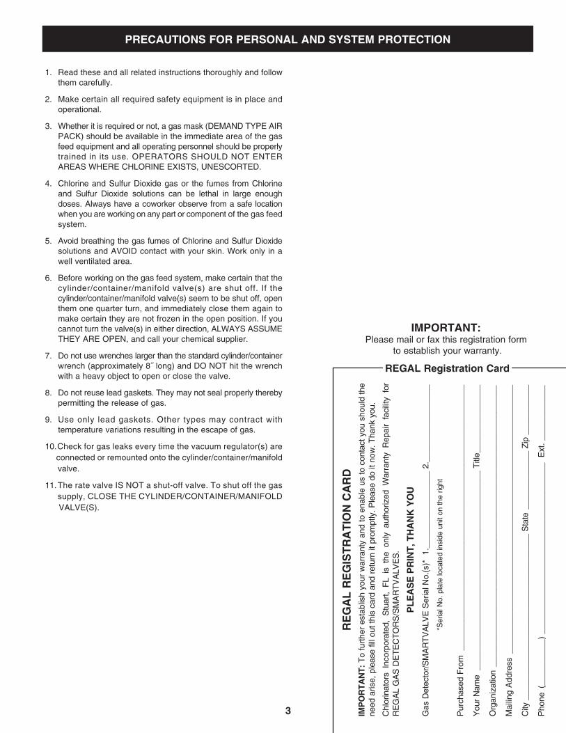
IMPORTANT: Please mail or fax this registration form
to establish your warranty. R
EG
AL
RE
GIS
TR
AT
ION
CA
RD
IMP
OR
TA
NT
: T
o fu
rthe
r es
tabl
ish
your
war
rant
y an
d to
ena
ble
us to
con
tact
you
sho
uld
the
need
aris
e, p
leas
e fil
l out
this
car
d an
d re
turn
it p
rom
ptly
. Ple
ase
do it
now
. Tha
nk y
ou.
Chl
orin
ator
s In
corp
orat
ed,
Stu
art,
FL
is t
he o
nly
auth
oriz
ed W
arra
nty
Rep
air
faci
lity
for
RE
GA
L G
AS
DE
TE
CT
OR
S/S
MA
RT
VA
LVE
S.
P
LE
AS
E P
RIN
T, T
HA
NK
YO
U
G
as D
etec
tor/
SM
AR
TV
ALV
E S
eria
l No.
(s)*
1.
____
____
____
____
_ 2.
____
____
____
____
_
*S
eria
l No.
pla
te lo
cate
d in
side
uni
t on
the
right
Pur
chas
ed F
rom
___
____
____
____
____
____
____
____
____
____
____
____
____
____
___
You
r N
ame
___
____
____
____
____
____
____
____
____
____
____
_ T
itle_
____
____
____
__
Org
aniz
atio
n _
____
____
____
____
____
____
____
____
____
____
____
____
____
____
____
_
Mai
ling
Add
ress
___
____
____
____
____
____
____
____
____
____
____
____
____
____
____
City
___
____
____
____
____
____
____
____
____
__ S
tate
___
____
____
__ Z
ip _
____
____
__
Pho
ne (
____
____
__)
____
____
____
____
____
____
____
____
____
_ E
xt.
____
____
____
REGAL Registration Card
3
A) Location of Components
B) Pipes, Tubing and Fittings
C) Electrical Interconnections
2.0 INSTALLATION
A) To Enter the Engineering Mode
B) Engineering Parameters
C) To Exit the Engineering Mode
4.0 ENGINEERING MODE
A) Linearizing (Calibrating) the SMARTVALVE
6.0 SYSTEM START-UP
A) Manual Operation
B) Automatic Operation
7.0 OPERATIONAL MODE
A) Calibrating the Analog Input(s)
B) Calibrating the Analog Output
C) Setting the Mechanical Zero
8.0 MAINTENANCE
9.0 SPECIFICATIONS
A) To Enter the Configuration Mode
B) Configuration Parameters
C) To Exit the Configuration Mode
5.0 CONFIGURATION MODE
A) The Importance of Mixing
B) The Importance of Proper Sizing of System Components
C) Transient Voltage Surge Suppression
1.0 INTRODUCTION 3.0 GENERAL INFORMATION PRIOR TO START-UP
IMPORTANT: Fill out and mail or fax the form on the reverse side
to establish your warranty.
CONTENTS
PLA
CE
S
TA
MP
H
ER
E
CH
LO
RIN
AT
OR
S IN
CO
RP
OR
AT
ED
1044 S
E D
ixie Cutoff R
oad S
tuart, FL 34994-3436
4
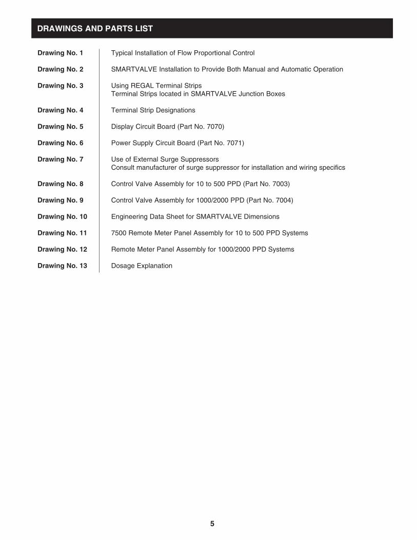
Drawing No. 1 Typical Installation of Flow Proportional Control Drawing No. 2 SMARTVALVE Installation to Provide Both Manual and Automatic Operation Drawing No. 3 Using REGAL Terminal Strips
Terminal Strips located in SMARTVALVE Junction Boxes Drawing No. 4 Terminal Strip Designations Drawing No. 5 Display Circuit Board (Part No. 7070) Drawing No. 6 Power Supply Circuit Board (Part No. 7071)
Drawing No. 7 Use of External Surge Suppressors
Consult manufacturer of surge suppressor for installation and wiring specifics Drawing No. 8 Control Valve Assembly for 10 to 500 PPD (Part No. 7003) Drawing No. 9 Control Valve Assembly for 1000/2000 PPD (Part No. 7004) Drawing No. 10 Engineering Data Sheet for SMARTVALVE Dimensions Drawing No. 11 7500 Remote Meter Panel Assembly for 10 to 500 PPD Systems Drawing No. 12 Remote Meter Panel Assembly for 1000/2000 PPD Systems Drawing No. 13 Dosage Explanation
DRAWINGS AND PARTS LIST
5
6
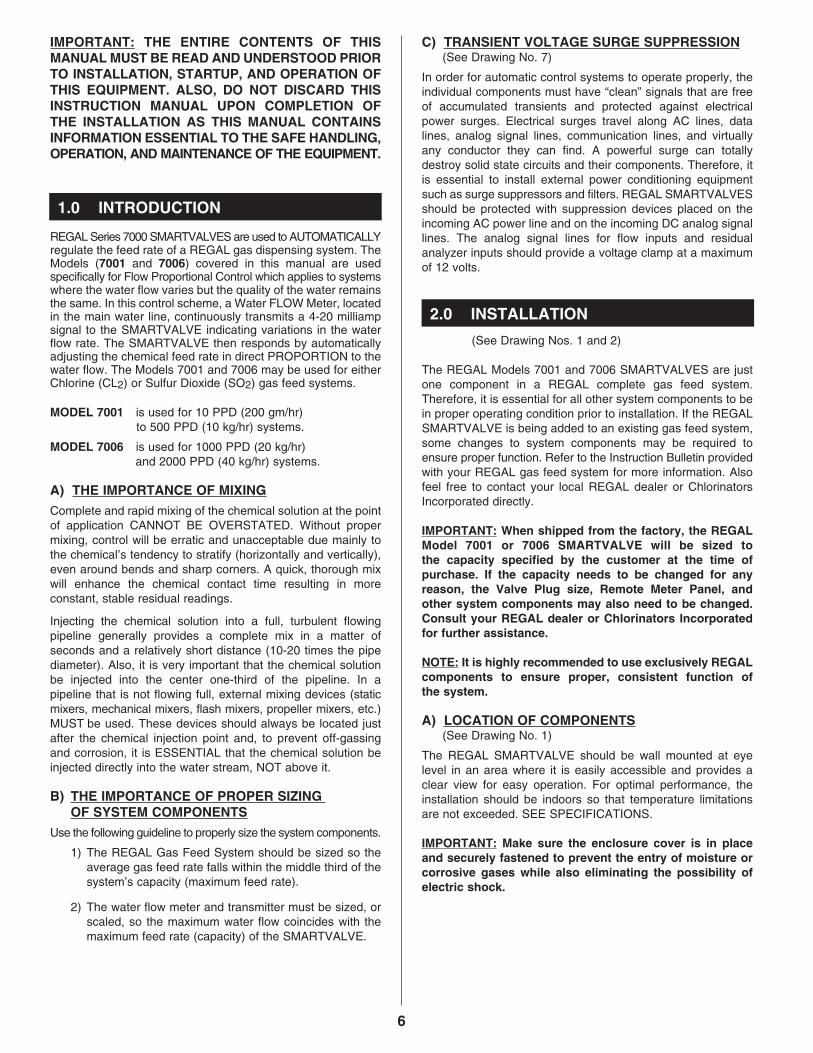
IMPORTANT: THE ENTIRE CONTENTS OF THIS MANUAL MUST BE READ AND UNDERSTOOD PRIOR TO INSTALLATION, STARTUP, AND OPERATION OF THIS EQUIPMENT. ALSO, DO NOT DISCARD THIS INSTRUCTION MANUAL UPON COMPLETION OF THE INSTALLATION AS THIS MANUAL CONTAINS INFORMATION ESSENTIAL TO THE SAFE HANDLING, OPERATION, AND MAINTENANCE OF THE EQUIPMENT.
REGAL Series 7000 SMARTVALVES are used to AUTOMATICALLY regulate the feed rate of a REGAL gas dispensing system. The Models (7001 and 7006) covered in this manual are used specifically for Flow Proportional Control which applies to systems where the water flow varies but the quality of the water remains the same. In this control scheme, a Water FLOW Meter, located in the main water line, continuously transmits a 4-20 milliamp signal to the SMARTVALVE indicating variations in the water flow rate. The SMARTVALVE then responds by automatically adjusting the chemical feed rate in direct PROPORTION to the water flow. The Models 7001 and 7006 may be used for either Chlorine (CL2) or Sulfur Dioxide (SO2) gas feed systems. MODEL 7001 is used for 10 PPD (200 gm/hr) to 500 PPD (10 kg/hr) systems. MODEL 7006 is used for 1000 PPD (20 kg/hr) and 2000 PPD (40 kg/hr) systems. A) THE IMPORTANCE OF MIXING Complete and rapid mixing of the chemical solution at the point of application CANNOT BE OVERSTATED. Without proper mixing, control will be erratic and unacceptable due mainly to the chemical’s tendency to stratify (horizontally and vertically), even around bends and sharp corners. A quick, thorough mix will enhance the chemical contact time resulting in more constant, stable residual readings. Injecting the chemical solution into a full, turbulent flowing pipeline generally provides a complete mix in a matter of seconds and a relatively short distance (10-20 times the pipe diameter). Also, it is very important that the chemical solution be injected into the center one-third of the pipeline. In a pipeline that is not flowing full, external mixing devices (static mixers, mechanical mixers, flash mixers, propeller mixers, etc.) MUST be used. These devices should always be located just after the chemical injection point and, to prevent off-gassing and corrosion, it is ESSENTIAL that the chemical solution be injected directly into the water stream, NOT above it.
B) THE IMPORTANCE OF PROPER SIZING
OF SYSTEM COMPONENTS Use the following guideline to properly size the system components.
1) The REGAL Gas Feed System should be sized so the average gas feed rate falls within the middle third of the system’s capacity (maximum feed rate).
2) The water flow meter and transmitter must be sized, or
scaled, so the maximum water flow coincides with the maximum feed rate (capacity) of the SMARTVALVE.
C) TRANSIENT VOLTAGE SURGE SUPPRESSION (See Drawing No. 7)
In order for automatic control systems to operate properly, the individual components must have “clean” signals that are free of accumulated transients and protected against electrical power surges. Electrical surges travel along AC lines, data lines, analog signal lines, communication lines, and virtually any conductor they can find. A powerful surge can totally destroy solid state circuits and their components. Therefore, it is essential to install external power conditioning equipment such as surge suppressors and filters. REGAL SMARTVALVES should be protected with suppression devices placed on the incoming AC power line and on the incoming DC analog signal lines. The analog signal lines for flow inputs and residual analyzer inputs should provide a voltage clamp at a maximum of 12 volts.
(See Drawing Nos. 1 and 2)
The REGAL Models 7001 and 7006 SMARTVALVES are just one component in a REGAL complete gas feed system. Therefore, it is essential for all other system components to be in proper operating condition prior to installation. If the REGAL SMARTVALVE is being added to an existing gas feed system, some changes to system components may be required to ensure proper function. Refer to the Instruction Bulletin provided with your REGAL gas feed system for more information. Also feel free to contact your local REGAL dealer or Chlorinators Incorporated directly. IMPORTANT: When shipped from the factory, the REGAL Model 7001 or 7006 SMARTVALVE will be sized to the capacity specified by the customer at the time of purchase. If the capacity needs to be changed for any reason, the Valve Plug size, Remote Meter Panel, and other system components may also need to be changed. Consult your REGAL dealer or Chlorinators Incorporated for further assistance. NOTE: It is highly recommended to use exclusively REGAL components to ensure proper, consistent function of the system. A) LOCATION OF COMPONENTS
(See Drawing No. 1) The REGAL SMARTVALVE should be wall mounted at eye level in an area where it is easily accessible and provides a clear view for easy operation. For optimal performance, the installation should be indoors so that temperature limitations are not exceeded. SEE SPECIFICATIONS. IMPORTANT: Make sure the enclosure cover is in place and securely fastened to prevent the entry of moisture or corrosive gases while also eliminating the possibility of electric shock.
1.0 INTRODUCTION
2.0 INSTALLATION
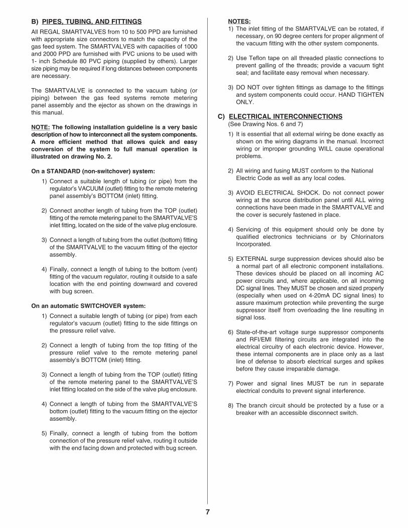
B) PIPES, TUBING, AND FITTINGS All REGAL SMARTVALVES from 10 to 500 PPD are furnished with appropriate size connectors to match the capacity of the gas feed system. The SMARTVALVES with capacities of 1000 and 2000 PPD are furnished with PVC unions to be used with 1- inch Schedule 80 PVC piping (supplied by others). Larger size piping may be required if long distances between components are necessary. The SMARTVALVE is connected to the vacuum tubing (or piping) between the gas feed systems remote metering panel assembly and the ejector as shown on the drawings in this manual. NOTE: The following installation guideline is a very basic description of how to interconnect all the system components. A more efficient method that allows quick and easy conversion of the system to full manual operation is illustrated on drawing No. 2. On a STANDARD (non-switchover) system:
1) Connect a suitable length of tubing (or pipe) from the regulator’s VACUUM (outlet) fitting to the remote metering panel assembly’s BOTTOM (inlet) fitting.
2) Connect another length of tubing from the TOP (outlet)
fitting of the remote metering panel to the SMARTVALVE’S inlet fitting, located on the side of the valve plug enclosure.
3) Connect a length of tubing from the outlet (bottom) fitting
of the SMARTVALVE to the vacuum fitting of the ejector assembly.
4) Finally, connect a length of tubing to the bottom (vent)
fitting of the vacuum regulator, routing it outside to a safe location with the end pointing downward and covered with bug screen.
On an automatic SWITCHOVER system:
1) Connect a suitable length of tubing (or pipe) from each regulator’s vacuum (outlet) fitting to the side fittings on the pressure relief valve.
2) Connect a length of tubing from the top fitting of the
pressure relief valve to the remote metering panel assembly’s BOTTOM (inlet) fitting.
3) Connect a length of tubing from the TOP (outlet) fitting
of the remote metering panel to the SMARTVALVE’S inlet fitting located on the side of the valve plug enclosure.
4) Connect a length of tubing from the SMARTVALVE’S
bottom (outlet) fitting to the vacuum fitting on the ejector assembly.
5) Finally, connect a length of tubing from the bottom
connection of the pressure relief valve, routing it outside with the end facing down and protected with bug screen.
NOTES: 1) The inlet fitting of the SMARTVALVE can be rotated, if
necessary, on 90 degree centers for proper alignment of the vacuum fitting with the other system components.
2) Use Teflon tape on all threaded plastic connections to
prevent galling of the threads; provide a vacuum tight seal; and facilitate easy removal when necessary.
3) DO NOT over tighten fittings as damage to the fittings
and system components could occur. HAND TIGHTEN ONLY.
C) ELECTRICAL INTERCONNECTIONS (See Drawing Nos. 6 and 7)
1) It is essential that all external wiring be done exactly as shown on the wiring diagrams in the manual. Incorrect wiring or improper grounding WILL cause operational problems.
2) All wiring and fusing MUST conform to the National
Electric Code as well as any local codes.
3) AVOID ELECTRICAL SHOCK. Do not connect power wiring at the source distribution panel until ALL wiring connections have been made in the SMARTVALVE and the cover is securely fastened in place.
4) Servicing of this equipment should only be done by
qualified electronics technicians or by Chlorinators Incorporated.
5) EXTERNAL surge suppression devices should also be
a normal part of all electronic component installations. These devices should be placed on all incoming AC power circuits and, where applicable, on all incoming DC signal lines. They MUST be chosen and sized properly (especially when used on 4-20mA DC signal lines) to assure maximum protection while preventing the surge suppressor itself from overloading the line resulting in signal loss.
6) State-of-the-art voltage surge suppressor components
and RFI/EMI filtering circuits are integrated into the electrical circuitry of each electronic device. However, these internal components are in place only as a last line of defense to absorb electrical surges and spikes before they cause irreparable damage.
7) Power and signal lines MUST be run in separate
electrical conduits to prevent signal interference.
8) The branch circuit should be protected by a fuse or a breaker with an accessible disconnect switch.
7
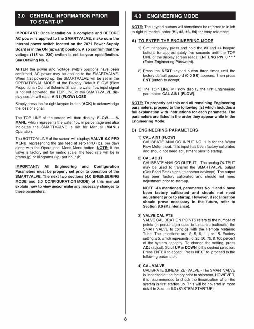
IMPORTANT: Once installation is complete and BEFORE AC power is applied to the SMARTVALVE, make sure the internal power switch located on the 7071 Power Supply Board is in the ON (upward) position. Also confirm that the voltage (115 vs. 230) switch is set to your specification. See Drawing No. 6. AFTER the power and voltage switch positions have been confirmed, AC power may be applied to the SMARTVALVE. When first powered up, the SMARTVALVE will be set in the OPERATIONAL MODE of the Factory Default FLOW (Flow Proportional) Control Scheme. Since the water flow input signal is not yet activated, the TOP LINE of the SMARTVALVE dis-play screen will read: AIN1 (FLOW) LOSS Simply press the far right keypad button (ACK) to acknowledge the loss of signal. The TOP LINE of the screen will then display: FLOW------% MANL, which represents the water flow in percentage and also indicates the SMARTVALVE is set for Manual (MANL) Operation. The BOTTOM LINE of the screen will display: VALVE 0.0 PPD MENU, representing the gas feed at zero PPD (lbs. per day) along with the Operational Mode Menu button. NOTE: If the valve is factory set for metric scale, the feed rate will be in grams (g) or kilograms (kg) per hour (h). IMPORTANT: All Engineering and Configuration Parameters must be properly set prior to operation of the SMARTVALVE. The next two sections (4.0 ENGINEERING MODE and 5.0 CONFIGURATION MODE) of this manual explain how to view and/or make any necessary changes to these parameters.
NOTE: The keypad buttons will sometimes be referred to in left to right numerical order (#1, #2, #3, #4) for easy reference. A) TO ENTER THE ENGINEERING MODE
1) Simultaneously press and hold the #3 and #4 keypad buttons for approximately five seconds until the TOP LINE of the display screen reads: ENT ENG PW 0 * * * (Enter Engineering Password).
2) Press the NEXT keypad button three times until the
factory default password (0 0 0 0) appears. Then press ENT (enter) to accept.
3) The TOP LINE will now display the first Engineering
parameter: CAL AIN1 (FLOW).
NOTE: To properly set this and all remaining Engineering parameters, proceed to the following list which includes a full explanation with instructions for each parameter. The parameters are listed in the order they appear while in the Engineering Mode. B) ENGINEERING PARAMETERS
1) CAL AIN1 (FLOW)
CALIBRATE ANALOG INPUT NO. 1 is for the Water Flow Meter Input. This input has been factory calibrated and should not need adjustment prior to startup.
2) CAL AOUT
CALIBRATE ANALOG OUTPUT – The analog OUTPUT may be used to transmit the SMARTVALVE output (Gas Feed Rate) signal to another device(s). The output has been factory calibrated and should not need adjustment prior to start-up.
NOTE: As mentioned, parameters No. 1 and 2 have been factory calibrated and should not need adjustment prior to startup. However, if recalibration should prove necessary in the future, refer to Section 8.0 (Maintenance).
3) VALVE CAL PTS
VALVE CALIBRATION POINTS refers to the number of points (in percentage) used to Linearize (calibrate) the SMARTVALVE to coincide with the Remote Metering Tube. The selections are: 2, 5, 6, 11, or 15. Factory setting is 5, which represents: 0, 25, 50, 75, & 100 percent of the system capacity. To change the setting, press ADJ (adjust). Scroll UP or DOWN to the desired selection. Press ENTER to accept. Press NEXT to proceed to the following parameter.
4) CAL VALVE
CALIBRATE (LINEARIZE) VALVE - The SMARTVALVE is linearized at the factory prior to shipment. HOWEVER, it is recommended to check the linearization when the system is first started up. This will be covered in more detail in Section 6.0 (SYSTEM STARTUP).
8
4.0 ENGINEERING MODE3.0 GENERAL INFORMATION PRIOR TO START-UP
5) VALVE SPEED VALVE SPEED allows the user to vary the speed of the SMARTVALVE stepper motor as it moves the position of the Valve Plug to adjust the Gas Feed Rate. The selections refer to seconds per revolution. Choices are: 0.5, 1.0, 1.5, 2.0, 3.0, 5.0, 7.5, & 10.0. Factory setting is 1.5.
NOTE: To change this and all remaining Engineering parameters, simply press ADJ. Scroll UP or DOWN to the desired value. Press ENTER to accept. Press NEXT to proceed to the following parameter.
6) VALVE HYS
VALVE HYSTERESIS places a “dead band” around the input signal(s) to limit response to minor signal variations. This helps prevent wear and tear on the stepper motor and feedback potentiometer. Selections in percentage are: Off, 0.06, 0.13, 0.25, 0.38, 0.50, 0.75, 1.00 and 2.00 %. Factory setting is 0.13 %.
7) FAIL OPERATION
FAIL OPERATION allows the user to choose how the SMARTVALVE will respond to a loss of the analog input signal(s). Selections are HOLD or DROP. HOLD will keep the Feed Rate at its current level and DROP will lower the Feed Rate to Zero.
NOTE: FAIL OPERATION is the final parameter to check/change before exiting the Engineering Mode.
C) TO EXIT THE ENGINEERING MODE
1) Press ESC (Escape).
2) After pressing Escape, you will be asked if you would like to ENTER NEW ENG PWD (Enter a new Engineering Password?).
3) Press NO to keep the existing password and to return to
the Main Operating Screen.
4) Press YES to change the password. The TOP LINE of the display will read: NEW ENG PW 0 ? ? ? a) Press the UP or DOWN keypad button(s) repeatedly
until the preferred FIRST digit is displayed. Then press NEXT to accept the new value.
b) The number 0 will appear as the second digit. Once
again, use UP or DOWN to scroll to the preferred number. Then press NEXT to accept and continue to the third digit.
c) Repeat the same steps to select the third and fourth digit.
d) Finally, press ENT (Enter) to accept the New
Password and return to the Main Operating Screen.
NOTE: At this time, if any changes to the settings were made while in the Engineering Mode, you will be asked if you want to SAVE CHANGES? Press YES or NO accordingly and you will return to the Main Operating Screen.
IMPORTANT: Once all Engineering parameter settings have been confirmed, proceed directly to the next section (5.0 CONFIGURATION MODE) to check and/or change the Configuration parameter settings. The Configuration Mode is used to set the basic valve parameters. Each parameter MUST be checked and/or changed prior to placing the system into operation. Simply enter the configuration mode as explained below and the para-meters will be displayed individually in the order they are listed. The list includes a detailed description of each parameter along with the settings and control schemes that apply. A) TO ENTER THE CONFIGURATION MODE
1) Press and hold the far right (#4) keypad button for approximately five seconds and you will be asked to enter the Configuration Password. The TOP LINE of the screen will read: ENTER CFG PW 0 * * * .
2) Press the NEXT keypad button three times until the
factory default password (0 0 0 0) is displayed.
3) Press ENT (Enter) and the first Configuration Parameter (FLOW UNITS) will appear.
NOTE: See page 10 for Configuration Parameters.
9
5.0 CONFIGURATION MODE
B) CONFIGURATION PARAMETERS PARAMETER DESCRIPTION AND SETTINGS
1) FLOW UNITS 2) FLOW RANGE 3) FLOW AVERAGE 4) VALVE UNITS 5) VALVE FS 6) SP1 MODE 7) SP2 MODE
8) SP3 MODE
The Water FLOW UNITS are available in % (percent), GPM (gallons per minute), MGD (million gallons per day), L/s (liters per second), m3s (cubic meters per second), and m3d (cubic meters per day). Factory set in %.
NOTE: To change this parameter and any other Configuration parameter, simply press (ADJ) adjust. Use the UP and DOWN buttons to scroll to the preferred selection. Press ENTER to accept, then press NEXT to continue to the following parameter. Sets the maximum WATER flow according to the selected FLOW UNITS. Since the factory setting for Flow Units is percent, the FLOW RANGE is set to 100 (%). Allows the Flow Signal to be averaged over a specific time period before the SMARTVALVE makes any adjustments. This helps prevent wear and tear on the stepper motor and feedback potentiometer. The settings available are 0.2, 0.4, 0.6, 0.8, 1, 2, 3, 5, 8 & 10 seconds. Factory set at 1. Units used to monitor and regulate the gas feed rate. The choices are PPD (lbs. per day), g/h (grams per hour) and kg/h (kilograms per hour). Factory setting is PPD. Valve Full Scale is the maximum gas feed rate (capacity) of the SMARTVALVE based upon the Valve Units. IMPORTANT: The SMARTVALVE is sized to the customer’s specification at the time of purchase. If the Full Scale of the SMARTVALVE needs to be changed, the valve plug and other system components may also need to be changed. SET POINT ONE MODE refers to the first of THREE available alarm Set Points. The Set Point Mode is used to activate alarm devices (if desired) and designate what condition the alarm represents. The selections are: OFF, LOW, or HIGH. If the SET POINT MODE setting is left in the factory default OFF position, no additional parameters will be made available for that particular alarm set point. However, if LOW or HIGH Mode is selected, the alarm is activated and the first of four (A thru D) Set Point parameters will be displayed as follows. A) SP1 SRC (SET POINT ONE SOURCE) refers to the source of the alarm. The choices will be FLOW (water flow level) and VALVE (gas feed rate). B) SP1 RELAY (SET POINT ONE RELAY). There are three (K1, K2, and K3) relay switches available on the SMARTVALVE’s Power Supply Board (7071). Each active alarm Set Point MUST be assigned to one relay. Each relay may be used for more than one set point. C) SP1 DELAY (SET POINT ONE DELAY) allows the user to set a time delay from when the alarm set point level is reached until the alarm actually turns on. The range available is 0 to 60 seconds. Factory setting is 0. D) SP1 HYS (SET POINT ONE HYSTERESIS) allows the user to set a level above (or below) the set point that the source must return to before the alarm turns off. This setting is based upon the units used to measure the alarm source. e.g.- If the water FLOW level is the alarm source and the range is in percentage (%) with a LOW level set point of 10%, a 2% hysteresis setting would require the water level to reach 12% before the alarm turns off. Factory setting is 0. SET POINT TWO MODE is used to activate (or de-activate) alarm Set Point No. 2. As is the case with Set Point No.1, the choices are: OFF, LOW, or HIGH. The factory setting (OFF) will de-activate the alarm and LOW or HIGH will activate it. If the alarm is activated, follow the same steps explained for alarm Set Point No. 1. SET POINT THREE MODE. Follow the same steps as explained for Set Points No. 1 and 2.
10
11
C) TO EXIT THE CONFIGURATION MODE
1) Follow the same steps as explained in Section 4C (TO EXIT THE ENGINEERING MODE).
NOTE: The system is now ready for start-up.
After all wiring and plumbing has been completed, and the Engineering and Configuration parameters have been confirmed, the system is ready for startup. Once the system is up and running, the TOP LINE of the SMARTVALVE display screen will show the water FLOW rate in the selected units. The ball float in the remote metering tube should read the same gas feed rate as shown on the bottom line of the SMARTVALVE display screen. ALWAYS READ THE CENTER OF THE BALL FLOAT.
IMPORTANT: The REGAL 7500 Remote Meter Panel MUST be configured for AUTOMATIC control. A) LINEARIZING (CALIBRATING) THE SMARTVALVE IMPORTANT: As previously mentioned, the SMARTVALVE has been calibrated (linearized) at the factory, however, it is still recommended that the user/installer checks and becomes familiar with the linearization process at startup, especially if all system components HAVE NOT been supplied by Chlorinators Incorporated. To check the linearization, proceed as follows:
1) ENTER THE ENGINEERING MODE as explained in Section 5.0.
2) Once in the Engineering Mode, scroll to the CAL VALVE
parameter. NOTE: Linearization will be based upon the factory set, 5-point linearization curve. Confirm this setting by checking the previous (LAST) parameter, VALVE CAL PTS (Valve Calibration Points).
3) While observing the ball float in the Remote Metering
Tube, press the ADJ (adjust) keypad button and the SMARTVALVE will start to drive to the ZERO feed rate position. The ball should come to rest on the bottom stop of the metering tube at exactly the same time the motor stops driving.
4) The Top Line of the SMARTVALVE display screen will
show a ZERO VOLTAGE reading of 0.45 V. NOTE: A voltage reading from 0.41 to 0.49 is acceptable. IMPORTANT: If for some reason the voltage reading falls outside of the acceptable range, contact Chlorinators Incorporated for assistance.
5) Once the correct ZERO voltage reading has been confirmed, press the NEXT keypad button and the SMARTVALVE will automatically open to the second linearization point which represents 25% of the system’s Full Scale (capacity). e.g.- For a 50 PPD system, 25% would be 12.5 PPD.
6) If the reading on the metering tube panel equals the
reading on the SMARTVALVE display screen, press ENTER and proceed to step 8.
7) If the readings DO NOT match, press ADJ (adjust). Use
the UP and DOWN keypad buttons to move the ball float to the correct (12.5 PPD) reading on the metering tube. Once the value matches the reading on the display, press ENTER to accept.
8) Press NEXT and the SMARTVALVE will automatically
open to the third linearization point representing 50% of the valve’s capacity. e.g.- 50% of a 50 PPD system equals 25 PPD. NOTE: Follow the same procedure described in steps 6 and 7 to complete the 50% point. Then continue on to the fourth linearization point (75%) and the fifth linearization point (100%).
9) Once the five linearization points have been set, press
the LAST button four times to return the valve back to the first point (0%). IMPORTANT: If the valve is not returned to 0%, it will continue to feed gas at 100% until you exit the Engineering Mode and reset the operation setting from Manual (MANL) to Automatic (AUTO).
10) Once the valve is reset to 0%, the Linearization is complete.
Simply press escape (ESC) to accept the Linearization settings. The CAL VALVE parameter is once again displayed. Press escape (ESC) a second time and you will be asked to SAVE CHANGES?. Press YES to confirm and you will return to the Main Operating Screen. Press MENU, then AUTO to return the valve to automatic operation.
NOTE: THE SMARTVALVE IS NOW READY FOR OPERATION. CONTINUE ON TO THE NEXT SECTION.
6.0 SYSTEM START-UP
12
The SMARTVALVE may be set to operate either automatically (AUTO) or manually (MANL), as needed. While in the Operational Mode, the TOP LINE of the main screen displays the water flow rate and also indicates if the valve is set for AUTO or MANL operation.To change the means of operation, press the MENU button. Only the non-active choice will appear on the screen. Press MANL or AUTO accordingly. The selection will be activated and appear on the top line (far right) of the display screen. A) MANUAL OPERATION The SMARTVALVE provides four separate ways to manually adjust the gas feed rate which include:
1) Fully Electric – In the event of loss of the analog input signal, you can use the keypad and digital display. To adjust the feed rate, place the SMARTVALVE into manual (MANL) operation as previously explained. Then press the VALVE button. Use the OPEN and CLOSE buttons to change the feed rate while using the digital display or metering tube as a guide.
2) Electric Manual – If the remote meter assembly is
temporarily out of service, use the thumbwheel and digital display. To adjust the feed rate, place the valve into MANL (manual) operation. Then turn the thumbwheel while using the digital display as a guide. IMPORTANT: To avoid gear damage and possibly upset the electrical zero setting, it is ESSENTIAL to place the valve into MANL operation PRIOR to turning the thumbwheel. Also, be sure to bypass the remote meter assembly by connecting the vacuum tubing from the regulator directly to the SMARTVALVE inlet fitting.
3) Manual – In the event of a power loss, use the thumb- wheel and remote meter assembly. To adjust the feed rate, simply turn the thumbwheel while using the remote meter ball float as a guide.
4) Fully Manual – If it is necessary to temporarily bypass
the SMARTVALVE entirely, use the remote meter rate valve assembly. See drawing No. 2 for proper installation.
B) AUTOMATIC OPERATION The Dosage and Alarm Set Point(s) are the only operational parameters for Flow Proportional Control.
1) DOSAGE – The dosage setting allows the user to adjust a ratio of the gas feed rate with respect to both the VARIABLE water flow and the NON-VARIABLE water quality. Settings are 0.0 to 4.0. Factory setting is 1.0.
NOTE: For a better understanding of DOSAGE, refer to page 27 and Drawing No. 13.
a) To view or change the Dosage setting, press the
MENU button, then press DOSE.
b) Use the UP and DOWN buttons to reach the preferred value. Press ENTER to accept and automatically return to the Main Operating Screen.
2) ALARM Set Point(s) – If any alarms were activated in
the Configuration Mode, the alarm Set Point Levels MUST then be set (or changed) in the Operational Mode. If no alarms have been activated, the ALARM selection will not appear when the MENU button is pressed. The alarm set points available for Flow Proportional Control are VALVE (gas feed rate) or FLOW (water flow).
a) To set, or change, the active alarm levels, press the
MENU button, then press ALARM. The display will read the set point number (SP1, SP2 or SP3); followed by the source (FLOW or VALVE); followed by the level (LOW or HIGH) in the applicable units.
b) To change the level, press ADJ (adjust). Use the UP
and DOWN buttons to display the preferred value. Then press ENTER to accept.
c) Press NEXT to proceed to any additional activated
Set Points.
d) Follow the same instructions for all Set Points. Then press ESC (escape) to return to the main operating screen.
7.0 OPERATIONAL MODE
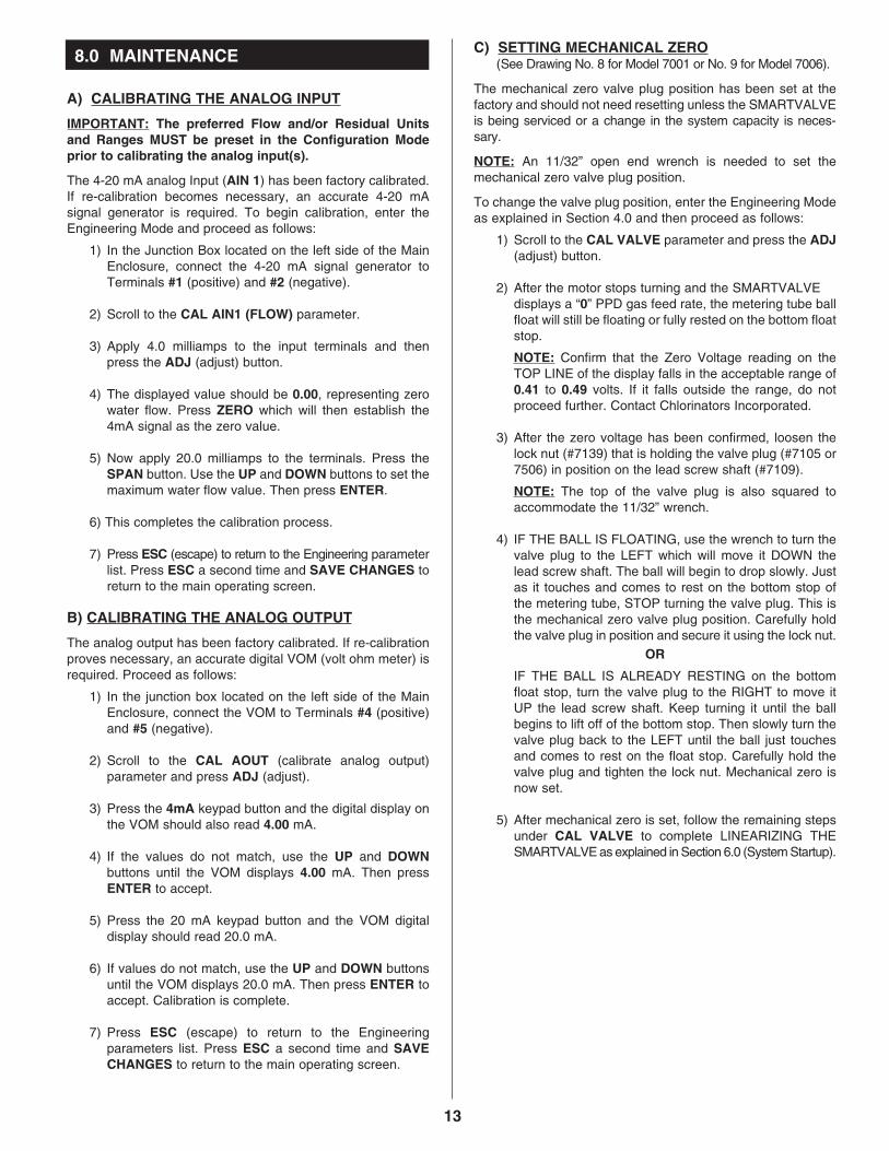
A) CALIBRATING THE ANALOG INPUT IMPORTANT: The preferred Flow and/or Residual Units and Ranges MUST be preset in the Configuration Mode prior to calibrating the analog input(s). The 4-20 mA analog Input (AIN 1) has been factory calibrated. If re-calibration becomes necessary, an accurate 4-20 mA signal generator is required. To begin calibration, enter the Engineering Mode and proceed as follows:
1) In the Junction Box located on the left side of the Main Enclosure, connect the 4-20 mA signal generator to Terminals #1 (positive) and #2 (negative).
2) Scroll to the CAL AIN1 (FLOW) parameter.
3) Apply 4.0 milliamps to the input terminals and then
press the ADJ (adjust) button.
4) The displayed value should be 0.00, representing zero water flow. Press ZERO which will then establish the 4mA signal as the zero value.
5) Now apply 20.0 milliamps to the terminals. Press the
SPAN button. Use the UP and DOWN buttons to set the maximum water flow value. Then press ENTER.
6) This completes the calibration process.
7) Press ESC (escape) to return to the Engineering parameter
list. Press ESC a second time and SAVE CHANGES to return to the main operating screen.
B) CALIBRATING THE ANALOG OUTPUT The analog output has been factory calibrated. If re-calibration proves necessary, an accurate digital VOM (volt ohm meter) is required. Proceed as follows:
1) In the junction box located on the left side of the Main Enclosure, connect the VOM to Terminals #4 (positive) and #5 (negative).
2) Scroll to the CAL AOUT (calibrate analog output)
parameter and press ADJ (adjust).
3) Press the 4mA keypad button and the digital display on the VOM should also read 4.00 mA.
4) If the values do not match, use the UP and DOWN
buttons until the VOM displays 4.00 mA. Then press ENTER to accept.
5) Press the 20 mA keypad button and the VOM digital
display should read 20.0 mA.
6) If values do not match, use the UP and DOWN buttons until the VOM displays 20.0 mA. Then press ENTER to accept. Calibration is complete.
7) Press ESC (escape) to return to the Engineering
parameters list. Press ESC a second time and SAVE CHANGES to return to the main operating screen.
C) SETTING MECHANICAL ZERO (See Drawing No. 8 for Model 7001 or No. 9 for Model 7006).
The mechanical zero valve plug position has been set at the factory and should not need resetting unless the SMARTVALVE is being serviced or a change in the system capacity is neces-sary. NOTE: An 11/32” open end wrench is needed to set the mechanical zero valve plug position. To change the valve plug position, enter the Engineering Mode as explained in Section 4.0 and then proceed as follows:
1) Scroll to the CAL VALVE parameter and press the ADJ (adjust) button.
2) After the motor stops turning and the SMARTVALVE
displays a “0” PPD gas feed rate, the metering tube ball float will still be floating or fully rested on the bottom float stop. NOTE: Confirm that the Zero Voltage reading on the TOP LINE of the display falls in the acceptable range of 0.41 to 0.49 volts. If it falls outside the range, do not proceed further. Contact Chlorinators Incorporated.
3) After the zero voltage has been confirmed, loosen the
lock nut (#7139) that is holding the valve plug (#7105 or 7506) in position on the lead screw shaft (#7109). NOTE: The top of the valve plug is also squared to accommodate the 11/32” wrench.
4) IF THE BALL IS FLOATING, use the wrench to turn the
valve plug to the LEFT which will move it DOWN the lead screw shaft. The ball will begin to drop slowly. Just as it touches and comes to rest on the bottom stop of the metering tube, STOP turning the valve plug. This is the mechanical zero valve plug position. Carefully hold the valve plug in position and secure it using the lock nut. OR IF THE BALL IS ALREADY RESTING on the bottom float stop, turn the valve plug to the RIGHT to move it UP the lead screw shaft. Keep turning it until the ball begins to lift off of the bottom stop. Then slowly turn the valve plug back to the LEFT until the ball just touches and comes to rest on the float stop. Carefully hold the valve plug and tighten the lock nut. Mechanical zero is now set.
5) After mechanical zero is set, follow the remaining steps
under CAL VALVE to complete LINEARIZING THE SMARTVALVE as explained in Section 6.0 (System Startup).
13
8.0 MAINTENANCE
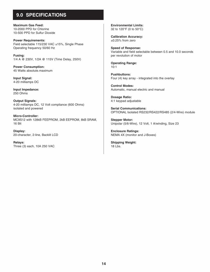
Maximum Gas Feed: 10-2000 PPD for Chlorine 10-500 PPD for Sulfur Dioxide Power Requirements: Field selectable 115/230 VAC ±15%, Single Phase Operating frequency 50/60 Hz Fusing: 1/4 A @ 230V, 1/2A @ 115V (Time Delay, 250V) Power Consumption: 45 Watts absolute.maximum Input Signal: 4-20 milliamps DC Input Impedance: 250 Ohms Output Signals: 4-20 milliamps DC, 12 Volt compliance (600 Ohms) isolated and powered Micro-Controller: MC9S12 with 128kB FEEPROM, 2kB EEPROM, 8kB SRAM, 16 Bit Display: 20-character, 2-line, Backlit LCD Relays: Three (3) each, 10A 250 VAC
Environmental Limits: 32 to 120°F (0 to 50°C) Calibration Accuracy: ±0.25% from zero Speed of Response: Variable and field selectable between 0.5 and 10.0 seconds per revolution of motor Operating Range: 10:1 Pushbuttons: Four (4) key array - integrated into the overlay Control Modes: Automatic, manual electric and manual Dosage Ratio: 4:1 keypad adjustable Serial Communications: OPTIONAL Isolated RS232/RS422/RS485 (2/4-Wire) module Stepper Motor: Unipolar (5/6-Wire), 12 Volt, 1 A/winding, Size 23 Enclosure Ratings: NEMA 4X (monitor and J-Boxes) Shipping Weight: 18 Lbs.
9.0 SPECIFICATIONS
14
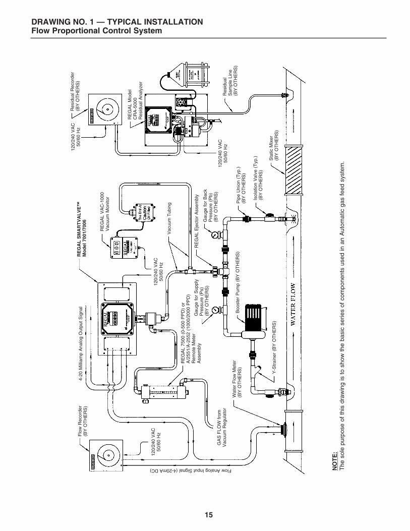
DRAWING NO. 1 — TYPICAL INSTALLATION Flow Proportional Control System
Flo
w R
ecor
der
(BY
OT
HE
RS
)4-
20 M
illia
mp
Ana
log
Out
put
Sig
nal
Vac
uum
Tub
ing
GA
S F
LOW
from
V
acuu
m R
egul
ator
RE
GA
L 75
00 (
0-50
0 P
PD
) or
A
/255
1/A
-255
2 (1
000/
2000
PP
D)
Rem
ote
Met
er
Ass
embl
y
Isol
atio
n V
alve
(T
yp.)
(B
Y O
TH
ER
S)
Boo
ster
Pum
p (B
Y O
TH
ER
S)
RE
GA
L E
ject
or A
ssem
bly
Y-S
trai
ner
(BY
OT
HE
RS
)
Pip
e U
nion
(T
yp.)
(B
Y O
TH
ER
S)
Gau
ge f
or S
uppl
y P
ress
ure
(Ps)
(B
Y O
TH
ER
S)
Gau
ge f
or B
ack
Pre
ssur
e (P
b)
(BY
OT
HE
RS
)
RE
GA
L M
odel
C
RA
-500
0
Res
idua
l Ana
lyze
r
RE
GA
L V
AC
-100
0 V
acuu
m M
onito
r
Sta
tic M
ixer
(B
Y O
TH
ER
S)
Res
idua
l S
ampl
e Li
ne
(BY
OT
HE
RS
)
120/
240
VA
C
50/6
0 H
z
120/
240
VA
C
50/6
0 H
z
120/
240
VA
C
50/6
0 H
z
120/
240
VA
C
50/6
0 H
zR
EG
AL
SM
AR
TV
AL
VE
™
Mo
del
700
1/70
06
Res
idua
l Rec
orde
r (B
Y O
TH
ER
S)
Wat
er F
low
Met
er
(BY
OT
HE
RS
)
Flow Analog Input Signal (4-20mA DC) NO
TE
: T
he s
ole
purp
ose
of t
his
draw
ing
is t
o sh
ow t
he b
asic
ser
ies
of c
ompo
nent
s us
ed in
an
Aut
omat
ic g
as f
eed
syst
em.
15
16
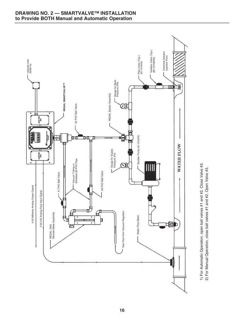
DRAWING NO. 2 — SMARTVALVE™ INSTALLATION to Provide BOTH Manual and Automatic Operation
RE
GA
L 75
00
Rem
ote
Met
er A
ssem
bly
Gas
Flo
w fr
om V
acuu
m R
egul
ator
Vac
uum
Tub
ing
or
Sch
edul
e 80
PV
C P
ipe
Boo
ster
Pum
p (B
Y O
TH
ER
S)
RE
GA
L E
ject
or A
ssem
bly
#2 P
VC
Bal
l Val
ve
#1 P
VC
Bal
l Val
ve
#3 P
VC
Bal
l Val
ve
Che
mic
al S
olut
ion
In
ject
ion
Poi
nt
Wat
er F
low
Met
er
4-20
mA
Ana
log
Flo
w I
nput
Sig
nal
4-20
Mill
iam
p A
nalo
g O
utpu
t S
igna
l
1) F
or A
utom
atic
Ope
ratio
n, o
pen
ball
valv
es #
1 an
d #2
. C
lose
Val
ve #
3.
2) F
or M
anua
l Ope
ratio
n, c
lose
bal
l val
ves
#1 a
nd #
2. O
pen
Val
ve #
3.Gau
ge f
or S
uppl
y P
ress
ure
(Ps)
G
auge
for
Bac
k P
ress
ure
(Pb)
Isol
atio
n V
alve
(T
yp.)
(B
Y O
TH
ER
S)
Pip
e U
nion
(T
yp.)
(B
Y O
TH
ER
S)
120/
240
VA
C
50/6
0 H
z
RE
GA
L S
MA
RT
VA
LV
E™
17
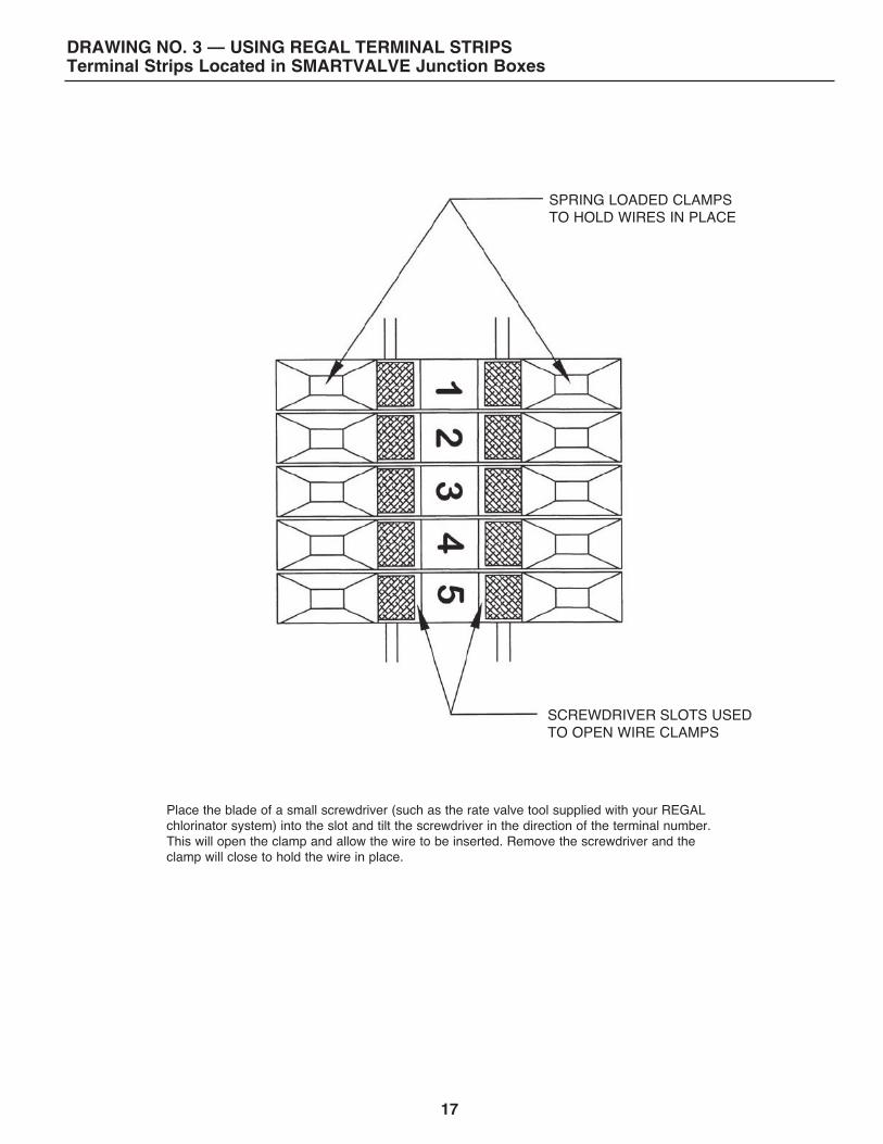
DRAWING NO. 3 — USING REGAL TERMINAL STRIPS Terminal Strips Located in SMARTVALVE Junction Boxes
Place the blade of a small screwdriver (such as the rate valve tool supplied with your REGAL chlorinator system) into the slot and tilt the screwdriver in the direction of the terminal number. This will open the clamp and allow the wire to be inserted. Remove the screwdriver and the clamp will close to hold the wire in place.
SCREWDRIVER SLOTS USED TO OPEN WIRE CLAMPS
SPRING LOADED CLAMPS TO HOLD WIRES IN PLACE
18
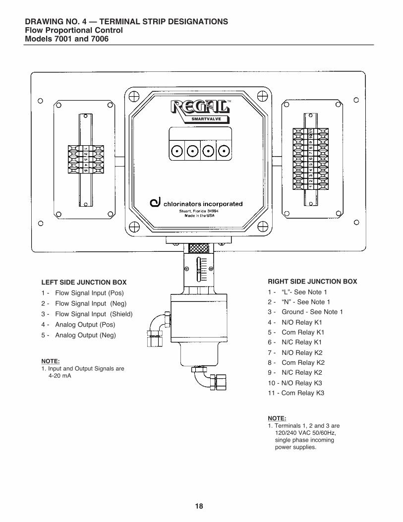
LEFT SIDE JUNCTION BOX
1 - Flow Signal Input (Pos)
2 - Flow Signal Input (Neg)
3 - Flow Signal Input (Shield)
4 - Analog Output (Pos)
5 - Analog Output (Neg)
NOTE: 1. Input and Output Signals are 4-20 mA
RIGHT SIDE JUNCTION BOX
1 - “L”- See Note 1
2 - “N” - See Note 1
3 - Ground - See Note 1
4 - N/O Relay K1
5 - Com Relay K1
6 - N/C Relay K1
7 - N/O Relay K2
8 - Com Relay K2
9 - N/C Relay K2
10 - N/O Relay K3
11 - Com Relay K3
NOTE: 1. Terminals 1, 2 and 3 are 120/240 VAC 50/60Hz, single phase incoming power supplies.
DRAWING NO. 4 — TERMINAL STRIP DESIGNATIONS Flow Proportional Control Models 7001 and 7006
SMARTVALVE
19
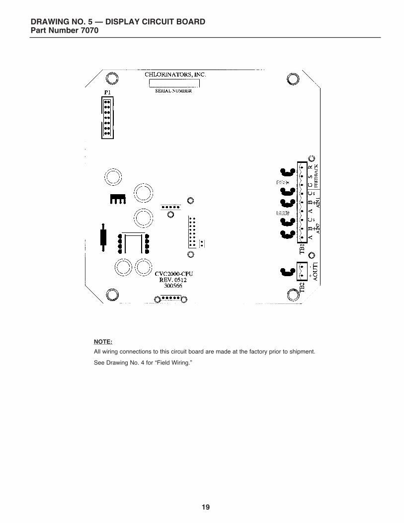
DRAWING NO. 5 — DISPLAY CIRCUIT BOARD Part Number 7070
NOTE: All wiring connections to this circuit board are made at the factory prior to shipment. See Drawing No. 4 for “Field Wiring.”
20
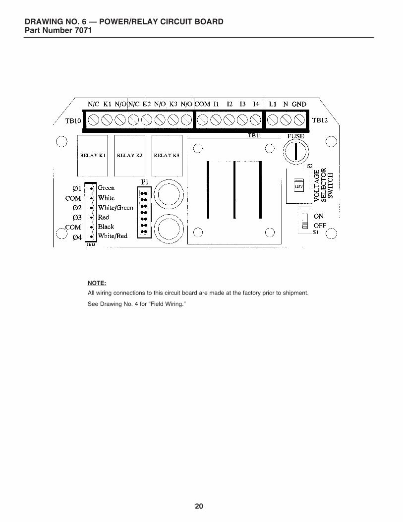
DRAWING NO. 6 — POWER/RELAY CIRCUIT BOARD Part Number 7071
NOTE: All wiring connections to this circuit board are made at the factory prior to shipment. See Drawing No. 4 for “Field Wiring.”
21
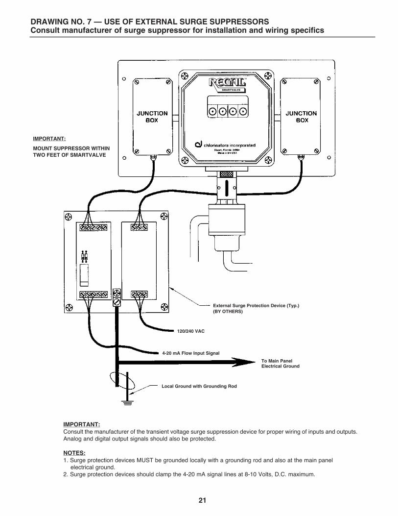
DRAWING NO. 7 — USE OF EXTERNAL SURGE SUPPRESSORS Consult manufacturer of surge suppressor for installation and wiring specifics
IMPORTANT: MOUNT SUPPRESSOR WITHIN TWO FEET OF SMARTVALVE
120/240 VAC
4-20 mA Flow Input Signal
To Main Panel Electrical Ground
Local Ground with Grounding Rod
External Surge Protection Device (Typ.) (BY OTHERS)
IMPORTANT: Consult the manufacturer of the transient voltage surge suppression device for proper wiring of inputs and outputs. Analog and digital output signals should also be protected. NOTES: 1. Surge protection devices MUST be grounded locally with a grounding rod and also at the main panel electrical ground. 2. Surge protection devices should clamp the 4-20 mA signal lines at 8-10 Volts, D.C. maximum.
SMARTVALVE
22
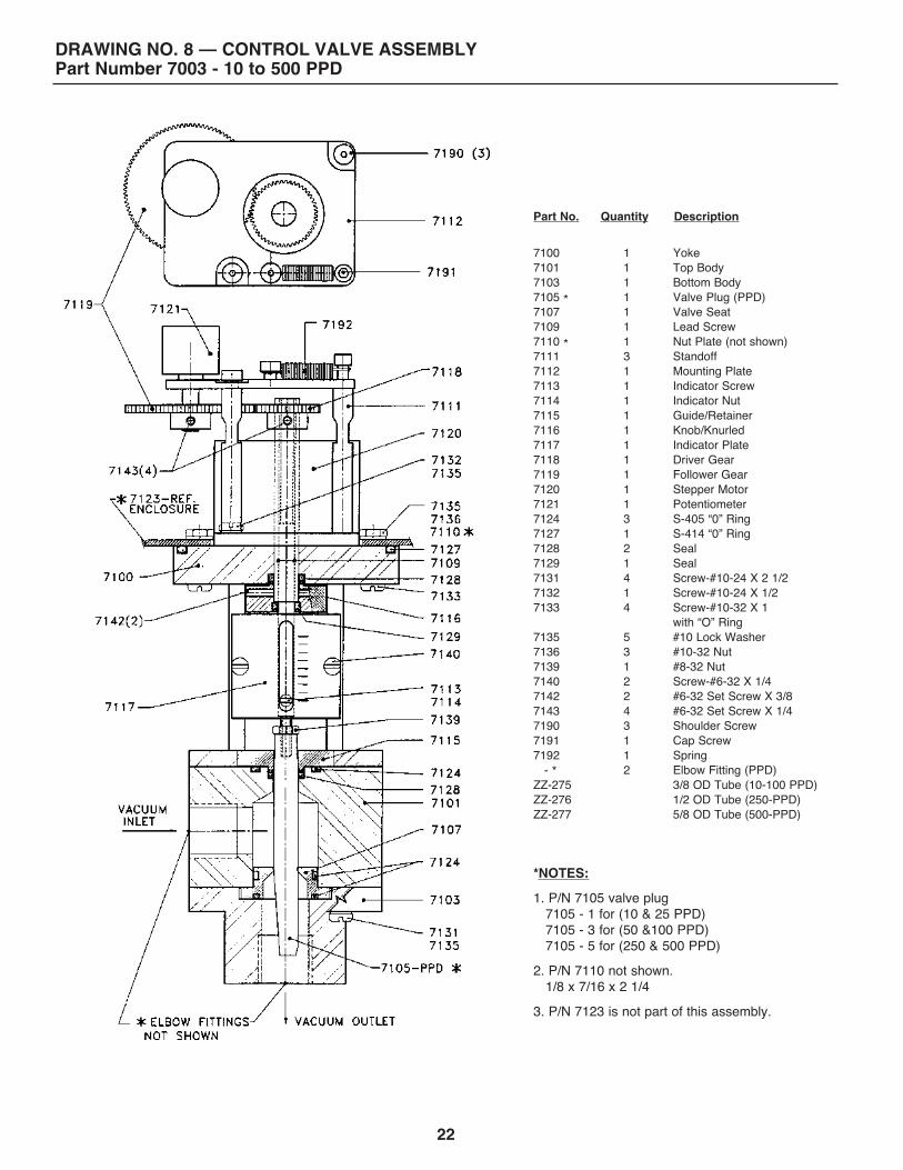
DRAWING NO. 8 — CONTROL VALVE ASSEMBLY Part Number 7003 - 10 to 500 PPD
Part No. Quantity Description 7100 1 Yoke 7101 1 Top Body 7103 1 Bottom Body 7105 * 1 Valve Plug (PPD) 7107 1 Valve Seat 7109 1 Lead Screw 7110 * 1 Nut Plate (not shown) 7111 3 Standoff 7112 1 Mounting Plate 7113 1 Indicator Screw 7114 1 Indicator Nut 7115 1 Guide/Retainer 7116 1 Knob/Knurled 7117 1 Indicator Plate 7118 1 Driver Gear 7119 1 Follower Gear 7120 1 Stepper Motor 7121 1 Potentiometer 7124 3 S-405 “0” Ring 7127 1 S-414 “0” Ring 7128 2 Seal 7129 1 Seal 7131 4 Screw-#10-24 X 2 1/2 7132 1 Screw-#10-24 X 1/2 7133 4 Screw-#10-32 X 1 with “O” Ring 7135 5 #10 Lock Washer 7136 3 #10-32 Nut 7139 1 #8-32 Nut 7140 2 Screw-#6-32 X 1/4 7142 2 #6-32 Set Screw X 3/8 7143 4 #6-32 Set Screw X 1/4 7190 3 Shoulder Screw 7191 1 Cap Screw 7192 1 Spring - * 2 Elbow Fitting (PPD) ZZ-275 3/8 OD Tube (10-100 PPD) ZZ-276 1/2 OD Tube (250-PPD) ZZ-277 5/8 OD Tube (500-PPD) *NOTES: 1. P/N 7105 valve plug 7105 - 1 for (10 & 25 PPD) 7105 - 3 for (50 &100 PPD) 7105 - 5 for (250 & 500 PPD) 2. P/N 7110 not shown. 1/8 x 7/16 x 2 1/4 3. P/N 7123 is not part of this assembly.
23
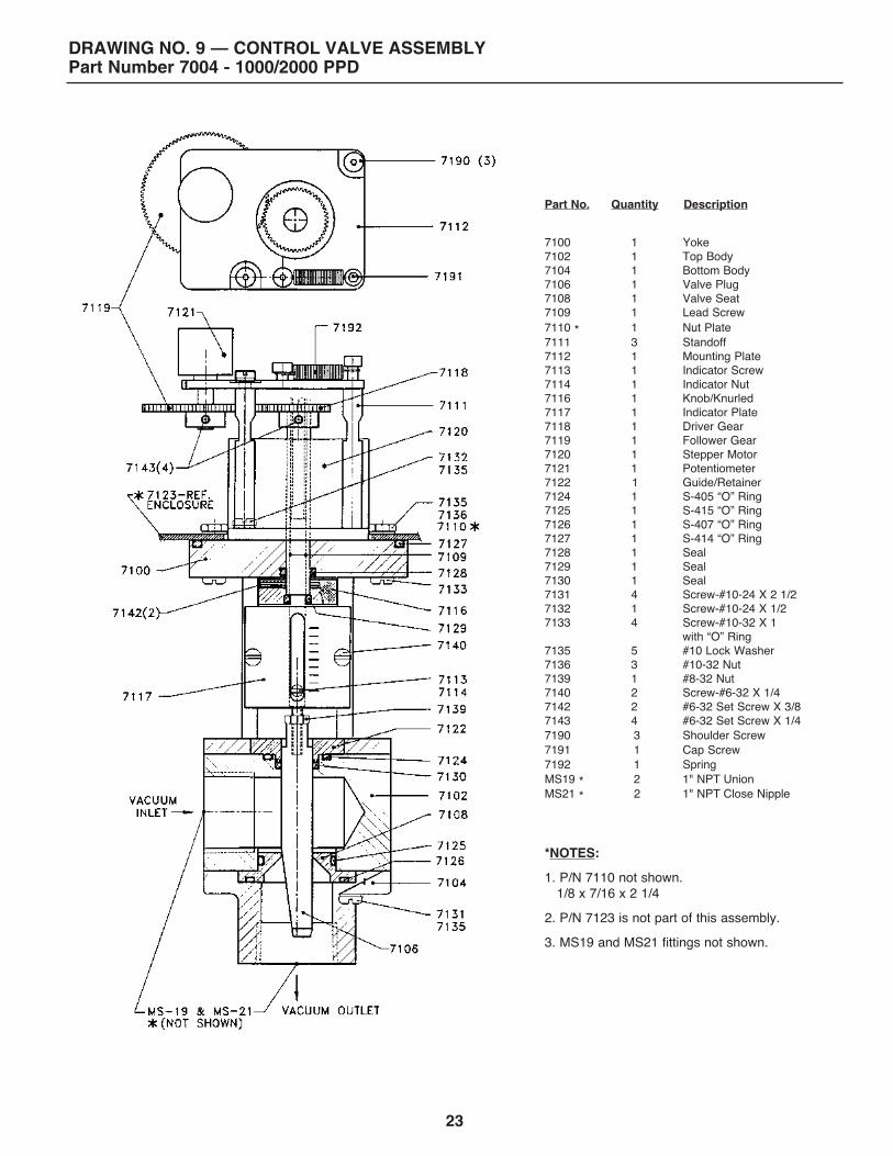
DRAWING NO. 9 — CONTROL VALVE ASSEMBLY Part Number 7004 - 1000/2000 PPD
Part No. Quantity Description 7100 1 Yoke 7102 1 Top Body 7104 1 Bottom Body 7106 1 Valve Plug 7108 1 Valve Seat 7109 1 Lead Screw 7110 * 1 Nut Plate 7111 3 Standoff 7112 1 Mounting Plate 7113 1 Indicator Screw 7114 1 Indicator Nut 7116 1 Knob/Knurled 7117 1 Indicator Plate 7118 1 Driver Gear 7119 1 Follower Gear 7120 1 Stepper Motor 7121 1 Potentiometer 7122 1 Guide/Retainer 7124 1 S-405 “O” Ring 7125 1 S-415 “O” Ring 7126 1 S-407 “O” Ring 7127 1 S-414 “O” Ring 7128 1 Seal 7129 1 Seal 7130 1 Seal 7131 4 Screw-#10-24 X 2 1/2 7132 1 Screw-#10-24 X 1/2 7133 4 Screw-#10-32 X 1 with “O” Ring 7135 5 #10 Lock Washer 7136 3 #10-32 Nut 7139 1 #8-32 Nut 7140 2 Screw-#6-32 X 1/4 7142 2 #6-32 Set Screw X 3/8 7143 4 #6-32 Set Screw X 1/4 7190 3 Shoulder Screw 7191 1 Cap Screw 7192 1 Spring MS19 * 2 1" NPT Union MS21 * 2 1" NPT Close Nipple *NOTES: 1. P/N 7110 not shown. 1/8 x 7/16 x 2 1/4 2. P/N 7123 is not part of this assembly. 3. MS19 and MS21 fittings not shown.
24
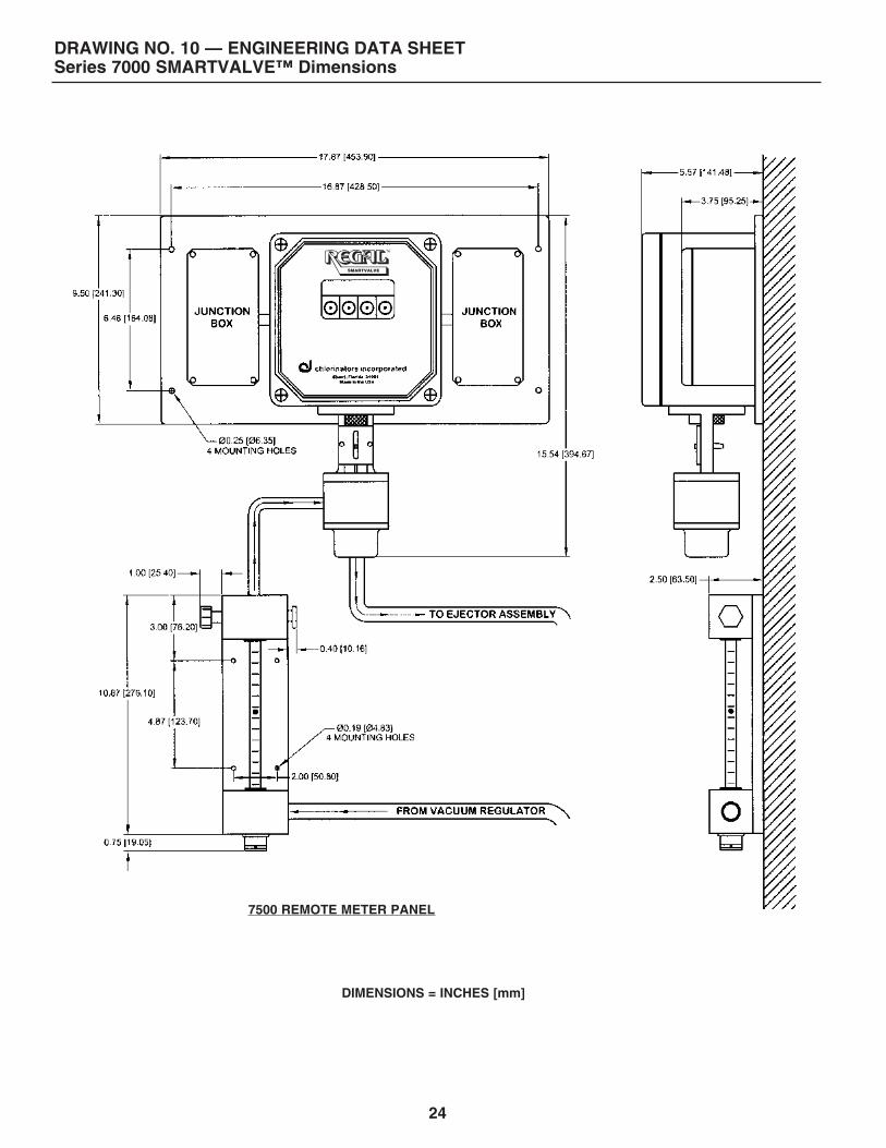
DRAWING NO. 10 — ENGINEERING DATA SHEET Series 7000 SMARTVALVE™ Dimensions
DIMENSIONS = INCHES [mm]
7500 REMOTE METER PANEL
SMARTVALVE
25
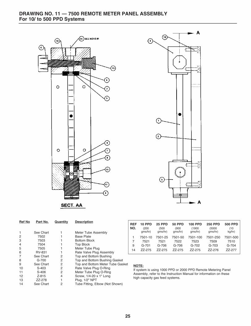
DRAWING NO. 11 — 7500 REMOTE METER PANEL ASSEMBLY For 10/ to 500 PPD Systems
Ref No Part No. Quantity Description 1 See Chart 1 Meter Tube Assembly 2 7502 1 Base Plate 3 7503 1 Bottom Block 4 7504 1 Top Block 5 7505 1 Meter Tube Plug 6 RV-831 1 Rate Valve Plug Assembly 7 See Chart 2 Top and Bottom Bushing 8 G-700 2 Top and Bottom Bushing Gasket 9 See Chart 2 Top and Bottom Meter Tube Gasket 10 S-403 2 Rate Valve Plug O-Ring 11 S-406 2 Meter Tube Plug O-Ring 12 Z-815 4 Screw, 1/4-20 x 1" Long 13 ZZ-278 1 Plug, 1/2" NPT 14 See Chart 2 Tube Fitting, Elbow (Not Shown)
NOTE: If system is using 1000 PPD or 2000 PPD Remote Metering Panel Assembly, refer to the Instruction Manual for information on these high capacity gas feed systems.
REF 10 PPD 25 PPD 50 PPD 100 PPD 250 PPD 500 PPD NO. (200 (500 (900 (1900 (5000 (10 gms/hr) gms/hr) gms/hr) gms/hr) gms/hr) kg/hr)
1 7501-10 7501-25 7501-50 7501-100 7501-250 7501-500 7 7521 7521 7522 7523 7509 7510 9 G-701 G-706 G-706 G-702 G-703 G-704 14 ZZ-275 ZZ-275 ZZ-275 ZZ-275 ZZ-276 ZZ-277
26
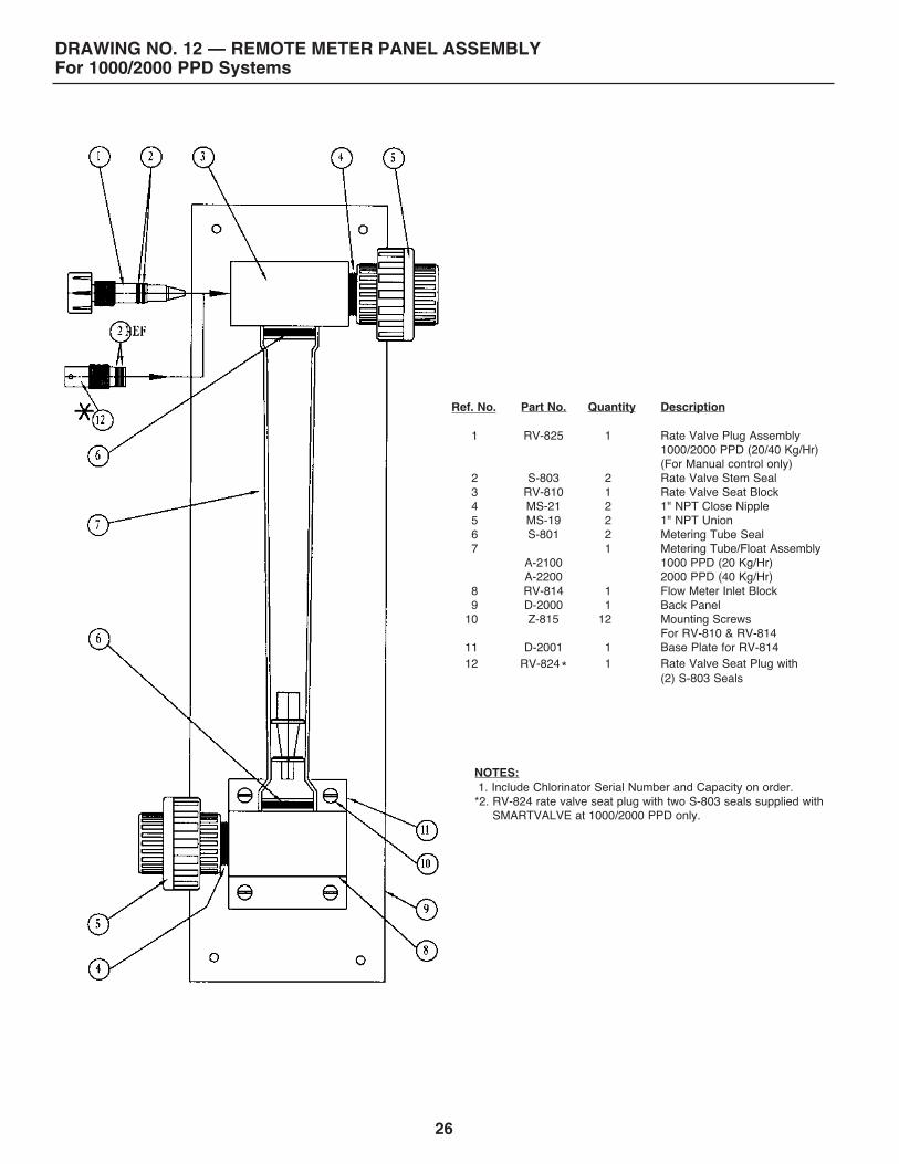
DRAWING NO. 12 — REMOTE METER PANEL ASSEMBLY For 1000/2000 PPD Systems
Quantity
1 2 1 2 2 2 1 1 1 12 1 1
Description Rate Valve Plug Assembly 1000/2000 PPD (20/40 Kg/Hr) (For Manual control only) Rate Valve Stem Seal Rate Valve Seat Block 1" NPT Close Nipple 1" NPT Union Metering Tube Seal Metering Tube/Float Assembly 1000 PPD (20 Kg/Hr) 2000 PPD (40 Kg/Hr) Flow Meter Inlet Block Back Panel Mounting Screws For RV-810 & RV-814 Base Plate for RV-814 Rate Valve Seat Plug with (2) S-803 Seals
NOTES: 1. Include Chlorinator Serial Number and Capacity on order. *2. RV-824 rate valve seat plug with two S-803 seals supplied with SMARTVALVE at 1000/2000 PPD only.
Part No.
RV-825
S-803 RV-810 MS-21 MS-19 S-801
A-2100 A-2200 RV-814 D-2000 Z-815
D-2001
RV-824*
Ref. No. 1 2 3 4 5 6 7 8 9 10 11 12
DRAWING NO. 13 — DOSAGE EXPLANATION
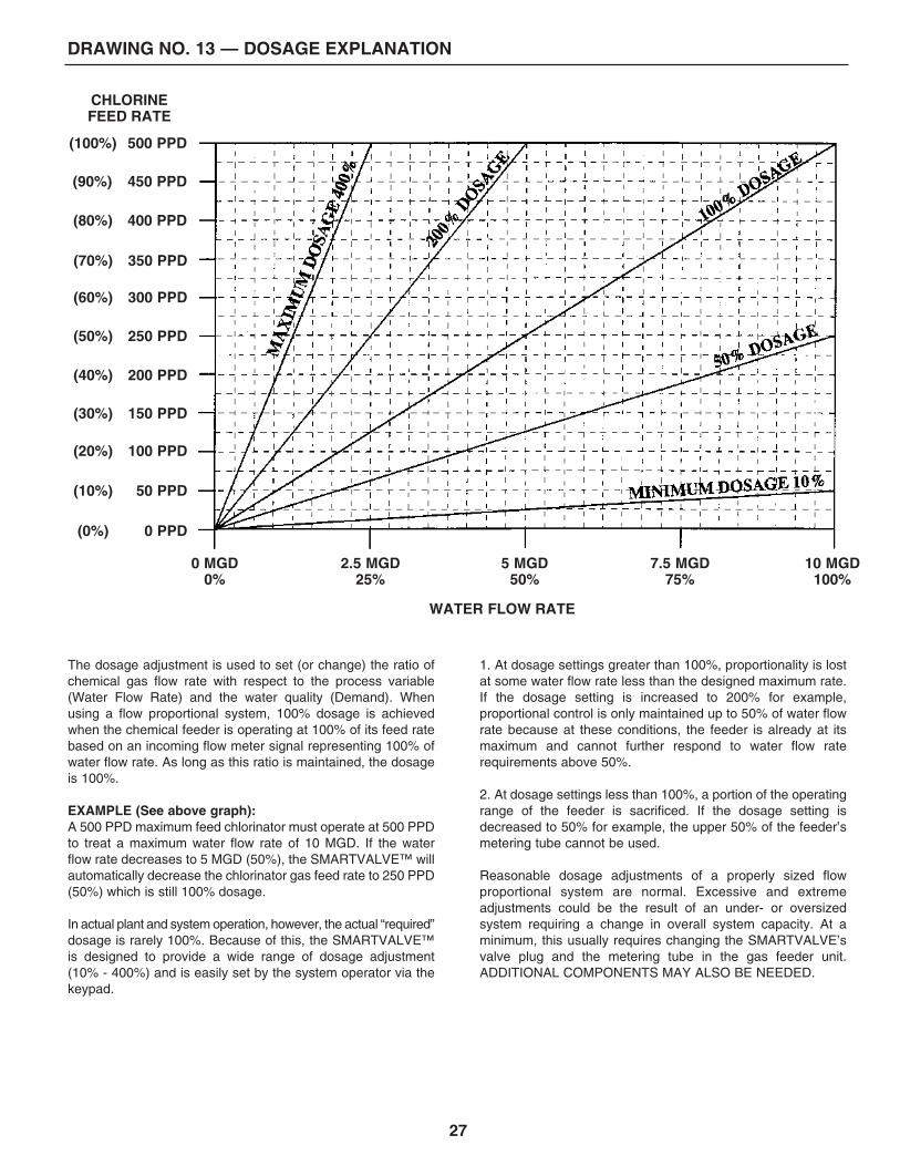
The dosage adjustment is used to set (or change) the ratio of chemical gas flow rate with respect to the process variable (Water Flow Rate) and the water quality (Demand). When using a flow proportional system, 100% dosage is achieved when the chemical feeder is operating at 100% of its feed rate based on an incoming flow meter signal representing 100% of water flow rate. As long as this ratio is maintained, the dosage is 100%. EXAMPLE (See above graph): A 500 PPD maximum feed chlorinator must operate at 500 PPD to treat a maximum water flow rate of 10 MGD. If the water flow rate decreases to 5 MGD (50%), the SMARTVALVE™ will automatically decrease the chlorinator gas feed rate to 250 PPD (50%) which is still 100% dosage. In actual plant and system operation, however, the actual “required” dosage is rarely 100%. Because of this, the SMARTVALVE™ is designed to provide a wide range of dosage adjustment (10% - 400%) and is easily set by the system operator via the keypad.
1. At dosage settings greater than 100%, proportionality is lost at some water flow rate less than the designed maximum rate. If the dosage setting is increased to 200% for example, proportional control is only maintained up to 50% of water flow rate because at these conditions, the feeder is already at its maximum and cannot further respond to water flow rate requirements above 50%. 2. At dosage settings less than 100%, a portion of the operating range of the feeder is sacrificed. If the dosage setting is decreased to 50% for example, the upper 50% of the feeder’s metering tube cannot be used. Reasonable dosage adjustments of a properly sized flow proportional system are normal. Excessive and extreme adjustments could be the result of an under- or oversized system requiring a change in overall system capacity. At a minimum, this usually requires changing the SMARTVALVE’s valve plug and the metering tube in the gas feeder unit. ADDITIONAL COMPONENTS MAY ALSO BE NEEDED.
CHLORINE FEED RATE
WATER FLOW RATE
0 MGD 0%
2.5 MGD 25%
5 MGD 50%
7.5 MGD 75%
10 MGD 100%
500 PPD
450 PPD
400 PPD
350 PPD
300 PPD
250 PPD
200 PPD
150 PPD
100 PPD
50 PPD
0 PPD
(100%)
(90%)
(80%)
(70%)
(60%)
(50%)
(40%)
(30%)
(20%)
(10%)
(0%)
27

Copyright 2019 Chlorinators Incorporated Printed in U.S.A. Pub. No. 0919-3
1044 SE Dixie Cutoff Road, Stuart, Florida 34994 USA Phone: (772) 288-4854 • Fax: (772) 287-3238 • www.regalchlorinators.com • Email: [email protected]
Related Documents