INSTALLATION AND SERVICE INSTRUCTION Siemens Energy & Automation 1 SD61 Rev 7 November 2005 Supersedes Rev 6 Models 61F, 61FE, 61L & 610F Booster Relays INTRODUCTION Booster relays are used to reproduce pneumatic signals in a 1:1 ratio when increased flow capacity and/or input isolation is required. The 61L is used primarily to supply and exhaust large volumes of air to increase the speed of response of a valve. Models 61F, 61FE and 610F are typically used in measurement circuits where a higher degree of accuracy of the 1:1 transmission is required. These models have preformed diaphragms for maximum accuracy and sensitivity. The Model 610F has an external zero adjustment for correction of an offset between the input and output pressures. Model 61FE has a tapped exhaust. This instruction has six major sections: Introduction, Installation, Principle of Operation, Maintenance, Warranty, and Parts List. Specifications Parameter Model 61L Models 61F, 61FE, & 610F Input and Output Ranges Normal Maximum 3 to 15 psig 0 to 100 psig 3 to 15 psig 0 to 50 psig Supply Pressure Normal Minimum Maximum 20 psi 1 psi above the highest output 100 psi 20 psi 1 psi above the highest output 50 psi Zero Adjustment None +/- 0.5 psi (Model 610F only) Ambient Temperature Limits -40°C to 82°C (-40°F to 180°F) INSTALLATION Shipping And Storage If the relay is to be stocked, stored, or shipped to another location prior to piping, make sure that the factory installed plastic plugs are in the ports to prevent entry of moisture, dirt, or other contaminants. Mounting Refer to Figure 1 for mounting dimensions. Mount the relay in a reasonably vibration free location. It can be mounted indoors or outdoors in any position. Operating temperature limits are listed in the Specifications section of this Instruction. The temperature in the selected location must not exceed the specified operating temperatures. CAUTION Exceeding the specified ambient temperature limits can adversely affect performance and may cause damage to the instrument.

Welcome message from author
This document is posted to help you gain knowledge. Please leave a comment to let me know what you think about it! Share it to your friends and learn new things together.
Transcript
INSTALLATION AND SERVICE INSTRUCTIONSiemensEnergy & Automation
1
SD61 Rev 7 November 2005 Supersedes Rev 6
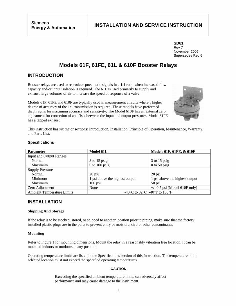
Models 61F, 61FE, 61L & 610F Booster Relays INTRODUCTION Booster relays are used to reproduce pneumatic signals in a 1:1 ratio when increased flow capacity and/or input isolation is required. The 61L is used primarily to supply and exhaust large volumes of air to increase the speed of response of a valve. Models 61F, 61FE and 610F are typically used in measurement circuits where a higher degree of accuracy of the 1:1 transmission is required. These models have preformed diaphragms for maximum accuracy and sensitivity. The Model 610F has an external zero adjustment for correction of an offset between the input and output pressures. Model 61FE has a tapped exhaust. This instruction has six major sections: Introduction, Installation, Principle of Operation, Maintenance, Warranty, and Parts List. Specifications Parameter Model 61L Models 61F, 61FE, & 610F Input and Output Ranges Normal Maximum
3 to 15 psig 0 to 100 psig
3 to 15 psig 0 to 50 psig
Supply Pressure Normal Minimum Maximum
20 psi 1 psi above the highest output 100 psi
20 psi 1 psi above the highest output 50 psi
Zero Adjustment None +/- 0.5 psi (Model 610F only) Ambient Temperature Limits -40°C to 82°C (-40°F to 180°F) INSTALLATION Shipping And Storage If the relay is to be stocked, stored, or shipped to another location prior to piping, make sure that the factory installed plastic plugs are in the ports to prevent entry of moisture, dirt, or other contaminants. Mounting Refer to Figure 1 for mounting dimensions. Mount the relay in a reasonably vibration free location. It can be mounted indoors or outdoors in any position. Operating temperature limits are listed in the Specifications section of this Instruction. The temperature in the selected location must not exceed the specified operating temperatures.
CAUTION
Exceeding the specified ambient temperature limits can adversely affect performance and may cause damage to the instrument.

SD61
2
Figure 1 Mounting Dimensions
Pneumatic Connections Refer to Figure 1 for the locations of pneumatic connections. The supply and output connections are 1/4" NPT. For all models except the 610F, the input connection is 1/8" NPT. The input connection for the 610F is 1/4" NPT.
Recommended piping to the relay is 1/4" O.D. Blow out all piping before connections are made to prevent the possibility of dirt or chips entering the relay. Use pipe sealant sparingly and then only on the male threads. A non-hardening sealant is strongly recommended.
CAUTION
Pressure in excess of 100 psi to any connection to a Model 61L may cause damage to the relay. Pressure in excess of 50 psi to any connection to a Model 61F, 61FE or 610F may damage the relay.
SD61
3
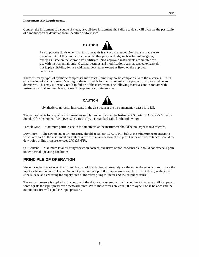
Instrument Air Requirements Connect the instrument to a source of clean, dry, oil-free instrument air. Failure to do so will increase the possibility of a malfunction or deviation from specified performance.
CAUTION
Use of process fluids other than instrument air is not recommended. No claim is made as to the suitability of this product for use with other process fluids, such as hazardous gases, except as listed on the appropriate certificate. Non-approved instruments are suitable for use with instrument air only. Optional features and modifications such as tapped exhaust do not imply suitability for use with hazardous gases except as listed on the approval certificate.
There are many types of synthetic compressor lubricants. Some may not be compatible with the materials used in construction of the instrument. Wetting of these materials by such an oil mist or vapor, etc., may cause them to deteriorate. This may ultimately result in failure of the instrument. The following materials are in contact with instrument air: aluminum, brass, Buna-N, neoprene, and stainless steel.
CAUTION
Synthetic compressor lubricants in the air stream at the instrument may cause it to fail.
The requirements for a quality instrument air supply can be found in the Instrument Society of America's "Quality Standard for Instrument Air" (ISA-S7.3). Basically, this standard calls for the following: Particle Size — Maximum particle size in the air stream at the instrument should be no larger than 3 microns. Dew Point — The dew point, at line pressure, should be at least 10°C (18°F) below the minimum temperature to which any part of the instrument air system is exposed at any season of the year. Under no circumstances should the dew point, at line pressure, exceed 2°C (35.6°F). Oil Content — Maximum total oil or hydrocarbon content, exclusive of non-condensable, should not exceed 1 ppm under normal operating conditions. PRINCIPLE OF OPERATION Since the effective areas on the top and bottom of the diaphragm assembly are the same, the relay will reproduce the input as the output in a 1:1 ratio. An input pressure on top of the diaphragm assembly forces it down, seating the exhaust face and unseating the supply face of the valve plunger, increasing the output pressure. The output pressure is applied to the bottom of the diaphragm assembly. It will continue to increase until its upward force equals the input pressure's downward force. When these forces are equal, the relay will be in balance and the output pressure will equal the input pressure.
SD61
4
MAINTENANCE
Normally, these instruments require no routine maintenance. It may become necessary to clean the plunger and seats if they accumulate enough foreign matter to prevent the valve plunger from seating properly. The valve plunger can be removed for cleaning by removing the retaining nut in the bottom forging. Access to the supply and exhaust seats is available after the valve plunger is removed.
CAUTION
Before disassembling the instrument, turn off supply air pressure to the instrument. When disassembling the instrument, make sure all parts are clean and free of dirt and debris. Reassembly is the reverse order of disassembly. Troubleshooting
If output pressure will not decrease with a decrease in input pressure: 1. Valve plunger is not seating correctly on the supply seat. Clean the valve plunger and seat. 2. Clogged exhaust.
If output pressure does not increase with an increase in input pressure: 1. Supply pressure may be too low. 2. Valve plunger is not seating properly in the exhaust seat. Clean the valve plunger and seat.
Parts Replacement Refer to the appropriate Parts List at the back of this instruction when performing maintenance on the relay. It provides a list of replacement parts and an exploded view. Product Support This section provides the Internet site addresses, e-mail addresses, telephone numbers, and related information for customers to access Siemens product support. When contacting Siemens for support:
• Please have complete product information at hand:
• For hardware, this information is provided on the product nameplate (part number or model number, serial number, and/or version).
• For most software, this information is given in the Help > About screen.
• If there is a problem with product operation:
• Is the problem intermittent or repeatable? What symptoms have been observed?
• What steps, configuration changes, loop modifications, etc. were performed before the problem occurred?
• What status messages, error messages, or LED indications are displayed?
• What troubleshooting steps have been performed?
• Is the installation environment (e.g. temperature, humidity) within the product’s specified operating parameters? For software, does the PC meet or exceed the minimum requirements (e.g. processor, memory, operating system)?
• A copy of the product Service Instruction, User’s Manual, or other technical literature should be at hand. The Siemens public Internet site (see the table) has current revisions of technical literature, in Portable Document Format (PDF), for downloading.
SD61
5
• To send an instrument to Siemens for repair, request a Return Material Authorization (RMA).
IMPORTANT
An instrument must be thoroughly cleaned (decontaminated) to remove any process materials, hazardous materials, or blood born pathogens prior to return for repair. Read and complete the Siemens RMA form(s).
Contact Information
Telephone +1 800 569 2132, option 2 for Siemens and Moore brand instruments Fax +1 215 646 3547 E-mail [email protected] Hours of Operation 8 a.m. to 4:45 p.m. eastern time Monday – Friday (except holidays) Public Internet Site www.sea.siemens.com/ia/
United States of America
Repair Service +1 215 646 7400 extension 3187
For contact information outside the U.S.A., visit the Siemens public Internet site (see the above table for the URL), locate “Customer Support Process Instrumentation,” and click on the Contact Tech Support link to access the Global Support link. Current revisions of technical publications for Siemens instruments can be found at the Siemens public Internet site. The publications are in Portable Document Format (PDF). WARRANTY (a) Seller warrants that on the date of shipment the goods are of the kind and quality described herein and are free of non-conformities in workmanship and material. This warranty does not apply to goods delivered by Seller but manufactured by others. (b) Buyer's exclusive remedy for a nonconformity in any item of the goods shall be the repair or the replacement (at Seller's option) of the item and any affected part of the goods. Seller’s obligation to repair or replace shall be in effect for a period of one (1) year from initial operation of the goods but not more than eighteen (18) months from Seller’s shipment of the goods, provided Buyer has sent written notice within that period of time to Seller that the goods do not conform to the above warranty. Repaired and replacement parts shall be warranted for the remainder of the original period of notification set forth above, but in no event less than 12 months from repair or replacement. At its expense, Buyer shall remove and ship to Seller any such nonconforming items and shall reinstall the repaired or replaced parts. Buyer shall grant Seller access to the goods at all reasonable times in order for Seller to determine any nonconformity in the goods. Seller shall have the right of disposal of items replaced by it. If Seller is unable or unwilling to repair or replace, or if repair or replacement does not remedy the nonconformity, Seller and Buyer shall negotiate an equitable adjustment in the contract price, which may include a full refund of the contract price for the nonconforming goods. (c) SELLER HEREBY DISCLAIMS ALL OTHER WARRANTIES, EXPRESS OR IMPLIED, EXCEPT THAT OF TITLE. SPECIFICALLY, IT DISCLAIMS THE IMPLIED WARRANTIES OF MERCHANTABILITY, FITNESS FOR A PARTICULAR PURPOSE, COURSE OF DEALING AND USAGE OF TRADE. (d) Buyer and successors of Buyer are limited to the remedies specified in this article and shall have no others for a nonconformity in the goods. Buyer agrees that these remedies provide Buyer and its successors with a minimum adequate remedy and are their exclusive remedies, whether Buyer's or its successors’ remedies are based on contract, warranty, tort (including negligence), strict liability, indemnity, or any other legal theory, and whether arising out of warranties, representations, instructions, installations, or non-conformities from any cause. (e) Note: The above does not apply to any software which may be furnished by Seller. In such cases, the attached Software License Addendum applies.

SD61
6
PARTS LIST Siemens Booster Relay, Model 61L
Drawing 4850PL
Rev 11/77 Supersedes 7/75
B/M 4850S12
* Recommended on-hand spare part. Always specify range, serial number, or other nameplate information when ordering spare parts.
IMPORTANT Service Parts Kits are available for servicing the instrument. Contact Siemens for available kits; refer to the Product Support section of this instruction. Some parts in this Parts List may not be available for separate purchase.
SD61
7
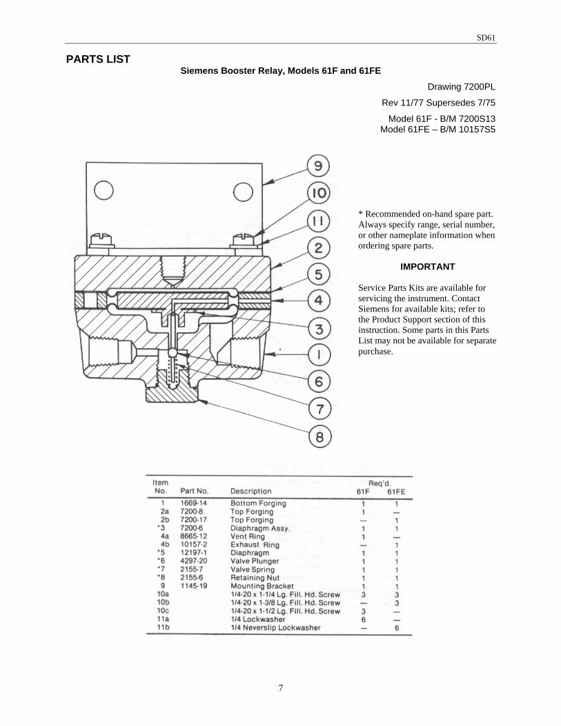
PARTS LIST Siemens Booster Relay, Models 61F and 61FE
Drawing 7200PL
Rev 11/77 Supersedes 7/75
Model 61F - B/M 7200S13 Model 61FE – B/M 10157S5
* Recommended on-hand spare part. Always specify range, serial number, or other nameplate information when ordering spare parts.
IMPORTANT Service Parts Kits are available for servicing the instrument. Contact Siemens for available kits; refer to the Product Support section of this instruction. Some parts in this Parts List may not be available for separate purchase.

SD61
8
PARTS LIST Siemens Booster Relay, Model 610F
Drawing 12196PL
Rev 5/80 Supersedes 12196-10, 1/76
B/M 12196S4
* Recommended on-hand spare part. Always specify range, serial number, or other nameplate information when ordering spare parts.
IMPORTANT Service Parts Kits are available for servicing the instrument. Contact Siemens for available kits; refer to the Product Support section of this instruction. Some parts in this Parts List may not be available for separate purchase.
Related Documents