Modelling the system dynamics of islanding asynchronous generators Håkon Molland Edvardsen Oslo, Norway [email protected] Dietmar Winkler Telemark University College, Norway [email protected] Abstract Asynchronous generators are often used for small hydro power stations with an installed power capa- city of under 1 MW . The reason for this is their ro- bustness and low cost. In order do be able to pro- duce active electrical power with an asynchronous generator once needs to provide enough excitation by means of reactive power provided by either the electrical grid or additional capacitors. But in asynchronous generators we can also find the phenomenon of self-excitation which allows the asynchronous generator to operate as a standalone unit. Investigation of the self-excitation process shows that significant over-voltages can occur if a generator with sufficient capacitors is suddenly dis- connected from the utility grid. The precondition for a successive voltage build-up is that the gener- ator is left with enough capacitive power and a low load after the disconnection. The Lønnestad radial in Seljord, Norway, is a distribution radial with both asynchronous and syn- chronous generators connected. In order to investig- ate the system dynamics in the radial after it is dis- connected from the rest of the 22kV distribution grid, the radial was modelled and simulated using Model- ica as modelling language. Keywords: modelica, asynchronous generators, self-excitation, islanding, electric power library 1 Introduction The main share of the electricity produced in Nor- way is based on utilisation of the nation’s large po- tential of hydro power. Today are nearly all the large waterfalls profitable for hydro power produc- tion already utilised, or protected against encroach- ment on nature. Due to this, there has for the last dec- ades been an expansion in the number of small hydro power stations below 10 MW . This is often minor projects where the power station is located near a small waterfall owned by a local landowner. These small hydro power stations are often con- nected to already existing distribution grids, due to the geographical location and installed capacity of these stations. This is often grids constructed for low capacities with purpose to distribute the electri- city out to the local consumers. Connection of power stations in these types of grids will therefore often change the situation of power flow in the grid, and lead to challenges regarding voltage stability and re- quirements for faults detection. 2 Theory The system that will be described in this paper consists of a electrical distribution radial to which one synchronous generator and several asynchronous generators are connected. This theory section will only cover the most important aspects of the complex power systems. 2.1 Asynchronous generators In the industry the asynchronous machine, or in- duction machine, is used in a wide variety of applic- ations with purpose of converting electrical power to mechanical work. The asynchronous machine is very economical, reliable, and easy to control, which are some of the reasons for its popularity. There are two main types of asynchronous machines based on the rotor construction; squirrel cage type, and wound ro- tor type. The simplicity and low cost, and the fact that they can be driven as a generator as well as a mo- tor, makes these machines very beneficial for wind power generation and small hydro power stations up to 1 MW . Unlike in wind power applications, the wound gen- erator is seldom used in small hydro power stations. The reason for this is that generators used in small hydro power stations generally is operated on the DOI 10.3384/ECP14096969 Proceedings of the 10 th International ModelicaConference March 10-12, 2014, Lund, Sweden 969

Welcome message from author
This document is posted to help you gain knowledge. Please leave a comment to let me know what you think about it! Share it to your friends and learn new things together.
Transcript

Modelling the system dynamics of islanding asynchronous generators
Håkon Molland EdvardsenOslo, Norway
Dietmar WinklerTelemark University College, Norway
Abstract
Asynchronous generators are often used for smallhydro power stations with an installed power capa-city of under 1MW . The reason for this is their ro-bustness and low cost. In order do be able to pro-duce active electrical power with an asynchronousgenerator once needs to provide enough excitationby means of reactive power provided by either theelectrical grid or additional capacitors.
But in asynchronous generators we can also findthe phenomenon of self-excitation which allows theasynchronous generator to operate as a standaloneunit. Investigation of the self-excitation processshows that significant over-voltages can occur if agenerator with sufficient capacitors is suddenly dis-connected from the utility grid. The preconditionfor a successive voltage build-up is that the gener-ator is left with enough capacitive power and a lowload after the disconnection.
The Lønnestad radial in Seljord, Norway, is adistribution radial with both asynchronous and syn-chronous generators connected. In order to investig-ate the system dynamics in the radial after it is dis-connected from the rest of the 22kV distribution grid,the radial was modelled and simulated using Model-ica as modelling language.
Keywords: modelica, asynchronous generators,self-excitation, islanding, electric power library
1 Introduction
The main share of the electricity produced in Nor-way is based on utilisation of the nation’s large po-tential of hydro power. Today are nearly all thelarge waterfalls profitable for hydro power produc-tion already utilised, or protected against encroach-ment on nature. Due to this, there has for the last dec-ades been an expansion in the number of small hydropower stations below 10MW . This is often minor
projects where the power station is located near asmall waterfall owned by a local landowner.
These small hydro power stations are often con-nected to already existing distribution grids, due tothe geographical location and installed capacity ofthese stations. This is often grids constructed forlow capacities with purpose to distribute the electri-city out to the local consumers. Connection of powerstations in these types of grids will therefore oftenchange the situation of power flow in the grid, andlead to challenges regarding voltage stability and re-quirements for faults detection.
2 Theory
The system that will be described in this paperconsists of a electrical distribution radial to whichone synchronous generator and several asynchronousgenerators are connected. This theory section willonly cover the most important aspects of the complexpower systems.
2.1 Asynchronous generators
In the industry the asynchronous machine, or in-duction machine, is used in a wide variety of applic-ations with purpose of converting electrical power tomechanical work. The asynchronous machine is veryeconomical, reliable, and easy to control, which aresome of the reasons for its popularity. There are twomain types of asynchronous machines based on therotor construction; squirrel cage type, and wound ro-tor type. The simplicity and low cost, and the factthat they can be driven as a generator as well as a mo-tor, makes these machines very beneficial for windpower generation and small hydro power stations upto 1MW .
Unlike in wind power applications, the wound gen-erator is seldom used in small hydro power stations.The reason for this is that generators used in smallhydro power stations generally is operated on the
DOI10.3384/ECP14096969
Proceedings of the 10th International ModelicaConferenceMarch 10-12, 2014, Lund, Sweden
969
principle of self-excitation without any rotor excita-tion. For such applications, generators with the squir-rel cage rotors can with advantage be used instead ofgenerators with wound rotor, since the squirrel cagemachine has lower cost.
2.1.1 The phenomena of self-excitation
Unlike the synchronous generator which gets itsmagnetisation from an internal magnetising source,and can be controlled to operate at a given fre-quency, the induction generator has no independentcontrol over the air-gap field. The induction gen-erator needs lagging reactive power to produce themain air-gap and winding leakage flux [1]. This phe-nomenon is referred to as self-excitation since thegenerator achieves its magnetising from a grid, orcapacitors which are connected to the stator termin-als. The phenomena permit utilisation of an induc-tion generator as a standalone unit without a voltagesource connected. Due to this the induction generatoris often referred to as a SEIG (Self-Excited InductionGenerator).
The phenomenon of self-excitation has beenknown for a long time, and a great deal of researchhas been done in the field of describing the phe-nomena and its transient behaviour. Various typesof models have been proposed, but the main part ofthem is rather complicated models expressed by thePark’s transform[2].
Initiation of the self-excitation process Self-excitation of a standalone generator may take place ifa sufficient amount of capacitors is connected to thegenerator. In order to initiate the self-excitation pro-cess, the residual flux in the rotor iron has to be highenough. The residual flux will induce a voltage in thestator when the generator is accelerated to a certainspeed. By connecting capacitors to the terminals ofthe generator, the induced stator voltage will cause aflow of current from the stator [3].
For a given capacitor, an SEIG running at no loadrequires only a minimum speed for the self-excitationto initiate [4].
Voltage build-up in the generator Once the pro-cess of self-excitation is initiated, the generatorvoltage builds up. The voltage build up can more eas-ily be understood by looking at the phasor diagram inFigure 1.
Figure 1: Phasor diagram before and after the self-excitation is initiated [3]
In this figure it can be observed that a current,Ic, starts to flow from the capacitors once the self-excitation is initiated. This current generates a flux,Ψgen, into the generator, with the same directionas the residual flux, Ψres. Therefore, the current,Igen, circulating in the stator reinforces the total flux,Ψtotal . This reinforced total flux causes an evenhigher stator voltage leading to successive increasein current and flux [3].
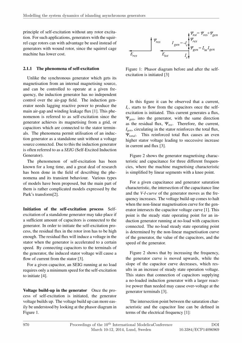
Figure 2 shows the generator magnetising charac-teristic and capacitance for three different frequen-cies, where the machine magnetising characteristicis simplified by linear segments with a knee point.
For a given capacitance and generator saturationcharacteristic, the intersection of the capacitance lineand the V-I-curve of the generator moves as the fre-quency increases. The voltage build-up comes to haltwhen the non-linear magnetisation curve for the gen-erator intersects the capacitor voltage curve [1]. Thispoint is the steady state operating point for an in-duction generator running at no-load with capacitorsconnected. The no-load steady state operating pointis determined by the non-linear magnetisation curveof the generator, the value of the capacitors, and thespeed of the generator.
Figure 2 shows that by increasing the frequency,the generator curve is moved upwards, while theslope of the capacitor curve decreases, which res-ults in an increase of steady state operation voltage.This states that connection of capacitors supplyinga no-loaded induction generator with a larger react-ive power than needed may cause over-voltage at thegenerator terminals [3].
The intersection point between the saturation char-acteristic and the capacitor line can be defined interms of the electrical frequency [1]:
Modelling the system dynamics of islanding asynchronous generators
970 Proceedings of the 10th International ModelicaConferenceMarch 10-12, 2014, Lund, Sweden
DOI10.3384/ECP14096969
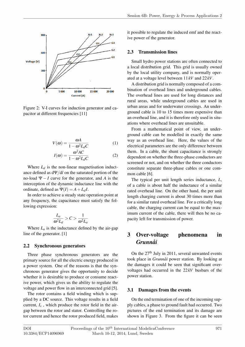
Figure 2: V-I curves for induction generator and ca-pacitor at different frequencies [11]
V (ω) =ωA
1−ω2LdC(1)
I(ω) =ω2AC
1−ω2LdC(2)
Where Ld is the non-linear magnetisation induct-ance defined as dΨ/dl on the saturated portion of theno-load Ψ− I curve for the generator, and A is theinterception of the dynamic inductance line with theordinate, defined as Ψ(I) = A + LdI.
In order to achieve a steady state operation point atany frequency, the capacitance must satisfy the fol-lowing expression:
La
ω2Ld>C >
1ω2La
Where La is the inductance defined by the air-gapline of the generator. [1]
2.2 Synchronous generators
Three phase synchronous generators are theprimary source for all the electric energy produced ina power system. One of the reasons is that the syn-chronous generator gives the opportunity to decidewhether it is desirable to produce or consume react-ive power, which gives us the ability to regulate thevoltage and power flow in an interconnected grid [5].
The rotor contains a field winding which is sup-plied by a DC source. This voltage results in a fieldcurrent, Ix , which produce the rotor field in the air-gap between the rotor and stator. Controlling the ro-tor current and hence the rotor produced field, makes
it possible to regulate the induced emf and the react-ive power of the generator.
2.3 Transmission lines
Small hydro power stations are often connected toa local distribution grid. This grid is usually ownedby the local utility company, and is normally oper-ated at a voltage level between 11kV and 22kV .
A distribution grid is normally composed of a com-bination of overhead lines and underground cables.The overhead lines are used for long distances andrural areas, while underground cables are used inurban areas and for underwater crossings. An under-ground cable is 10 to 15 times more expensive thanan overhead line, and it is therefore only used in situ-ations where overhead lines are unsuitable.
From a mathematical point of view, an under-ground cable can be modelled in exactly the sameway as an overhead line. Here, the values of theelectrical parameters are the only difference betweenthem. In a cable, the shunt capacitance is stronglydependent on whether the three-phase conductors arescreened or not, and on whether the three conductorsconstitute separate three-phase cables or one com-mon cable [6].
The typical per unit length series inductance, L,of a cable is about half the inductance of a similarrated overhead line. On the other hand, the per unitlength charging current is about 30 times more thanfor a similar rated overhead line. For a critically longcable, the charging current can be equal to the max-imum current of the cable, there will then be no ca-pacity left for transmission of power.
3 Over-voltage phenomena inGrunnåi
On the 27th July in 2011, several unwanted eventstook place in Grunnåi power station. By looking atthe damages it could be seen that significant over-voltages had occurred in the 22kV busbars of thepower station.
3.1 Damages from the events
On the end termination of one of the incoming sup-ply cables, a phase to ground fault had occurred. Twopictures of the end termination and its damage areshown in Figure 3. From the figure it can be seen
Session 6B: Power, Energy & Process Applications 2
DOI10.3384/ECP14096969
Proceedings of the 10th International ModelicaConferenceMarch 10-12, 2014, Lund, Sweden
971
that there has been heat generation in the end termin-ation.
Figure 3: Phase to ground fault on end terminationof supply cable
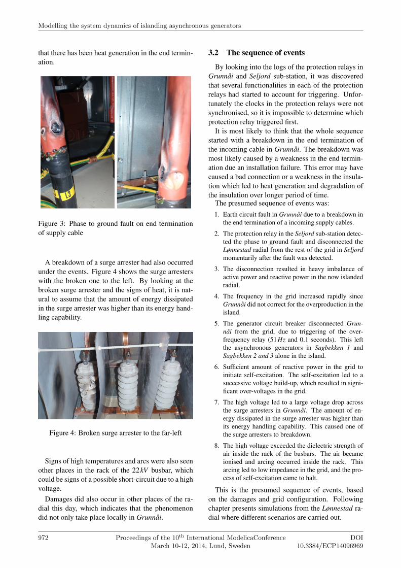
A breakdown of a surge arrester had also occurredunder the events. Figure 4 shows the surge arresterswith the broken one to the left. By looking at thebroken surge arrester and the signs of heat, it is nat-ural to assume that the amount of energy dissipatedin the surge arrester was higher than its energy hand-ling capability.
Figure 4: Broken surge arrester to the far-left
Signs of high temperatures and arcs were also seenother places in the rack of the 22kV busbar, whichcould be signs of a possible short-circuit due to a highvoltage.
Damages did also occur in other places of the ra-dial this day, which indicates that the phenomenondid not only take place locally in Grunnåi.
3.2 The sequence of events
By looking into the logs of the protection relays inGrunnåi and Seljord sub-station, it was discoveredthat several functionalities in each of the protectionrelays had started to account for triggering. Unfor-tunately the clocks in the protection relays were notsynchronised, so it is impossible to determine whichprotection relay triggered first.
It is most likely to think that the whole sequencestarted with a breakdown in the end termination ofthe incoming cable in Grunnåi. The breakdown wasmost likely caused by a weakness in the end termin-ation due an installation failure. This error may havecaused a bad connection or a weakness in the insula-tion which led to heat generation and degradation ofthe insulation over longer period of time.
The presumed sequence of events was:
1. Earth circuit fault in Grunnåi due to a breakdown inthe end termination of a incoming supply cables.
2. The protection relay in the Seljord sub-station detec-ted the phase to ground fault and disconnected theLønnestad radial from the rest of the grid in Seljordmomentarily after the fault was detected.
3. The disconnection resulted in heavy imbalance ofactive power and reactive power in the now islandedradial.
4. The frequency in the grid increased rapidly sinceGrunnåi did not correct for the overproduction in theisland.
5. The generator circuit breaker disconnected Grun-nåi from the grid, due to triggering of the over-frequency relay (51Hz and 0.1 seconds). This leftthe asynchronous generators in Sagbekken 1 andSagbekken 2 and 3 alone in the island.
6. Sufficient amount of reactive power in the grid toinitiate self-excitation. The self-excitation led to asuccessive voltage build-up, which resulted in signi-ficant over-voltages in the grid.
7. The high voltage led to a large voltage drop acrossthe surge arresters in Grunnåi. The amount of en-ergy dissipated in the surge arrester was higher thanits energy handling capability. This caused one ofthe surge arresters to breakdown.
8. The high voltage exceeded the dielectric strength ofair inside the rack of the busbars. The air becameionised and arcing occurred inside the rack. Thisarcing led to low impedance in the grid, and the pro-cess of self-excitation came to halt.
This is the presumed sequence of events, basedon the damages and grid configuration. Followingchapter presents simulations from the Lønnestad ra-dial where different scenarios are carried out.
Modelling the system dynamics of islanding asynchronous generators
972 Proceedings of the 10th International ModelicaConferenceMarch 10-12, 2014, Lund, Sweden
DOI10.3384/ECP14096969
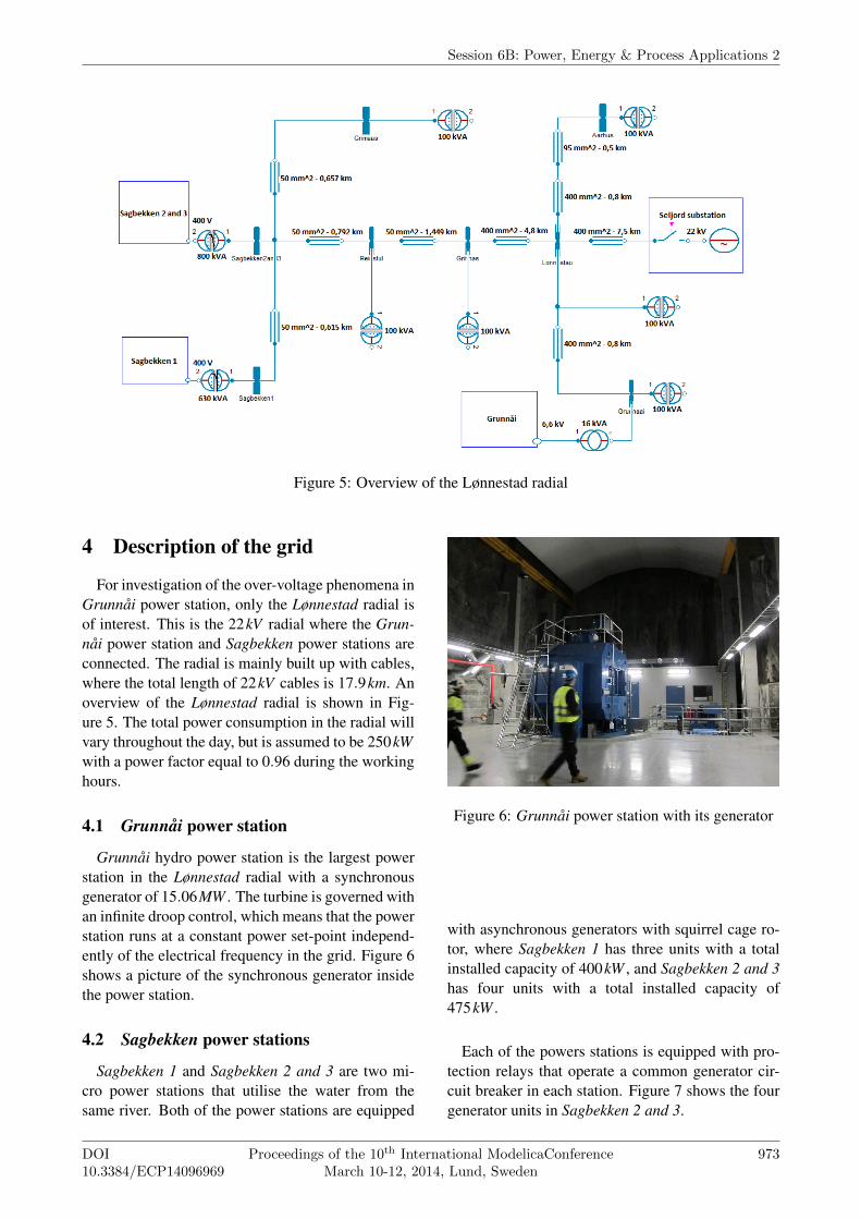
Figure 5: Overview of the Lønnestad radial
4 Description of the grid
For investigation of the over-voltage phenomena inGrunnåi power station, only the Lønnestad radial isof interest. This is the 22kV radial where the Grun-nåi power station and Sagbekken power stations areconnected. The radial is mainly built up with cables,where the total length of 22kV cables is 17.9km. Anoverview of the Lønnestad radial is shown in Fig-ure 5. The total power consumption in the radial willvary throughout the day, but is assumed to be 250kWwith a power factor equal to 0.96 during the workinghours.
4.1 Grunnåi power station
Grunnåi hydro power station is the largest powerstation in the Lønnestad radial with a synchronousgenerator of 15.06MW . The turbine is governed withan infinite droop control, which means that the powerstation runs at a constant power set-point independ-ently of the electrical frequency in the grid. Figure 6shows a picture of the synchronous generator insidethe power station.
4.2 Sagbekken power stations
Sagbekken 1 and Sagbekken 2 and 3 are two mi-cro power stations that utilise the water from thesame river. Both of the power stations are equipped
Figure 6: Grunnåi power station with its generator
with asynchronous generators with squirrel cage ro-tor, where Sagbekken 1 has three units with a totalinstalled capacity of 400kW , and Sagbekken 2 and 3has four units with a total installed capacity of475kW .
Each of the powers stations is equipped with pro-tection relays that operate a common generator cir-cuit breaker in each station. Figure 7 shows the fourgenerator units in Sagbekken 2 and 3.
Session 6B: Power, Energy & Process Applications 2
DOI10.3384/ECP14096969
Proceedings of the 10th International ModelicaConferenceMarch 10-12, 2014, Lund, Sweden
973
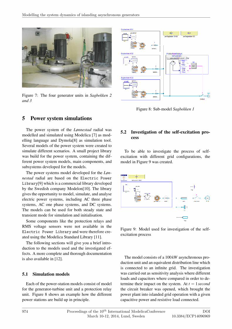
Figure 7: The four generator units in Sagbekken 2and 3
5 Power system simulations
The power system of the Lønnestad radial wasmodelled and simulated using Modelica [7] as mod-elling language and Dymola[8] as simulation tool.Several models of the power system were created tosimulate different scenarios. A small project librarywas build for the power system, containing the dif-ferent power system models, main components, andsubsystems developed for the models.
The power systems model developed for the Løn-nestad radial are based on the Electric PowerLibrary[9] which is a commercial library developedby the Swedish company Modelon[10]. The librarygives the opportunity to model, simulate, and analyseelectric power systems, including AC three phasesystems, AC one phase systems, and DC systems.The models can be used for both steady state andtransient mode for simulation and initialisation.
Some components like the protection relays andRMS voltage sensors were not available in theElectric Power Library and were therefore cre-ated using the Modelica Standard Library [11].
The following sections will give you a brief intro-duction to the models used and the investigated ef-fects. A more complete and thorough documentationis also available in [12].
5.1 Simulation models
Each of the power-station models consist of modelfor the generator-turbine unit and a protection relayunit. Figure 8 shows an example how the differentpower stations are build up in principle.
Figure 8: Sub-model Sagbekken 1
5.2 Investigation of the self-excitation pro-cess
To be able to investigate the process of self-excitation with different grid configurations, themodel in Figure 9 was created.
Figure 9: Model used for investigation of the self-excitation process
The model consists of a 100kW asynchronous pro-duction unit and an equivalent distribution line whichis connected to an infinite grid. The investigationwas carried out as sensitivity analysis where differentloads and capacitors where compared in order to de-termine their impact on the system. At t = 1secondthe circuit breaker was opened, which brought thepower plant into islanded grid operation with a givencapacitive power and resistive load connected.
Modelling the system dynamics of islanding asynchronous generators
974 Proceedings of the 10th International ModelicaConferenceMarch 10-12, 2014, Lund, Sweden
DOI10.3384/ECP14096969
5.2.1 Self-excited induction generator withoutcapacitors
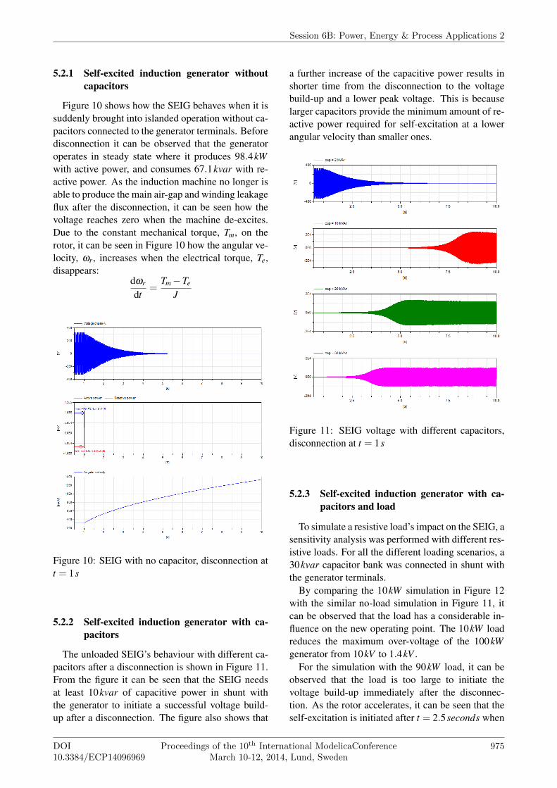
Figure 10 shows how the SEIG behaves when it issuddenly brought into islanded operation without ca-pacitors connected to the generator terminals. Beforedisconnection it can be observed that the generatoroperates in steady state where it produces 98.4kWwith active power, and consumes 67.1kvar with re-active power. As the induction machine no longer isable to produce the main air-gap and winding leakageflux after the disconnection, it can be seen how thevoltage reaches zero when the machine de-excites.Due to the constant mechanical torque, Tm, on therotor, it can be seen in Figure 10 how the angular ve-locity, ωr, increases when the electrical torque, Te,disappears:
dωr
dt=
Tm−Te
J
Figure 10: SEIG with no capacitor, disconnection att = 1s
5.2.2 Self-excited induction generator with ca-pacitors
The unloaded SEIG’s behaviour with different ca-pacitors after a disconnection is shown in Figure 11.From the figure it can be seen that the SEIG needsat least 10kvar of capacitive power in shunt withthe generator to initiate a successful voltage build-up after a disconnection. The figure also shows that
a further increase of the capacitive power results inshorter time from the disconnection to the voltagebuild-up and a lower peak voltage. This is becauselarger capacitors provide the minimum amount of re-active power required for self-excitation at a lowerangular velocity than smaller ones.
Figure 11: SEIG voltage with different capacitors,disconnection at t = 1s
5.2.3 Self-excited induction generator with ca-pacitors and load
To simulate a resistive load’s impact on the SEIG, asensitivity analysis was performed with different res-istive loads. For all the different loading scenarios, a30kvar capacitor bank was connected in shunt withthe generator terminals.
By comparing the 10kW simulation in Figure 12with the similar no-load simulation in Figure 11, itcan be observed that the load has a considerable in-fluence on the new operating point. The 10kW loadreduces the maximum over-voltage of the 100kWgenerator from 10kV to 1.4kV .
For the simulation with the 90kW load, it can beobserved that the load is too large to initiate thevoltage build-up immediately after the disconnec-tion. As the rotor accelerates, it can be seen that theself-excitation is initiated after t = 2.5seconds when
Session 6B: Power, Energy & Process Applications 2
DOI10.3384/ECP14096969
Proceedings of the 10th International ModelicaConferenceMarch 10-12, 2014, Lund, Sweden
975
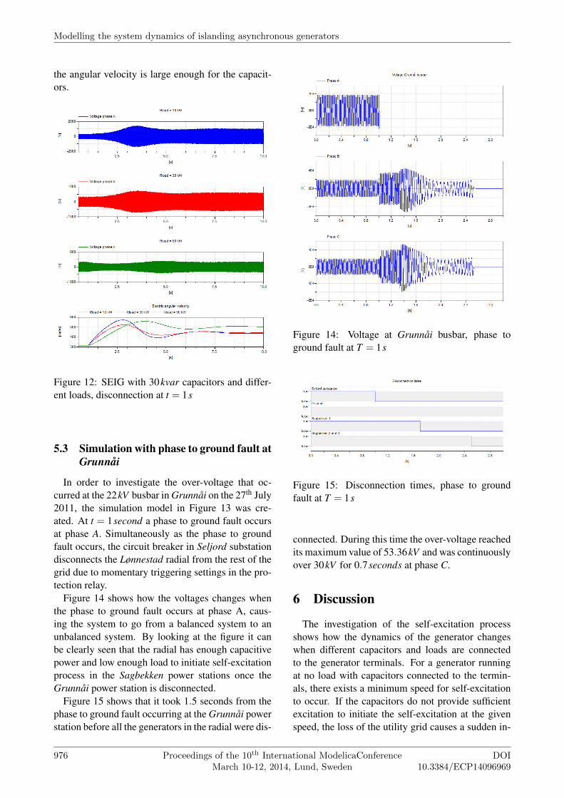
the angular velocity is large enough for the capacit-ors.
Figure 12: SEIG with 30kvar capacitors and differ-ent loads, disconnection at t = 1s
5.3 Simulation with phase to ground fault atGrunnåi
In order to investigate the over-voltage that oc-curred at the 22kV busbar in Grunnåi on the 27th July2011, the simulation model in Figure 13 was cre-ated. At t = 1second a phase to ground fault occursat phase A. Simultaneously as the phase to groundfault occurs, the circuit breaker in Seljord substationdisconnects the Lønnestad radial from the rest of thegrid due to momentary triggering settings in the pro-tection relay.
Figure 14 shows how the voltages changes whenthe phase to ground fault occurs at phase A, caus-ing the system to go from a balanced system to anunbalanced system. By looking at the figure it canbe clearly seen that the radial has enough capacitivepower and low enough load to initiate self-excitationprocess in the Sagbekken power stations once theGrunnåi power station is disconnected.
Figure 15 shows that it took 1.5 seconds from thephase to ground fault occurring at the Grunnåi powerstation before all the generators in the radial were dis-
Figure 14: Voltage at Grunnåi busbar, phase toground fault at T = 1s
Figure 15: Disconnection times, phase to groundfault at T = 1s
connected. During this time the over-voltage reachedits maximum value of 53.36kV and was continuouslyover 30kV for 0.7seconds at phase C.
6 Discussion
The investigation of the self-excitation processshows how the dynamics of the generator changeswhen different capacitors and loads are connectedto the generator terminals. For a generator runningat no load with capacitors connected to the termin-als, there exists a minimum speed for self-excitationto occur. If the capacitors do not provide sufficientexcitation to initiate the self-excitation at the givenspeed, the loss of the utility grid causes a sudden in-
Modelling the system dynamics of islanding asynchronous generators
976 Proceedings of the 10th International ModelicaConferenceMarch 10-12, 2014, Lund, Sweden
DOI10.3384/ECP14096969

Figure 13: Model of Lønnestad radial with phase to ground fault
crease in the slope of the equivalent capacitor lineseen by the generator [1]. This change may cause acomplete or partial loss of the generator excitation.Due to this, the generator fails to produce an electro-magnetic torque large enough to overcome the mech-anical torque, which results in acceleration of the ro-tor.
Unless the residual flux is lost, the self-excitationcan be initiated when the angular velocity has in-creased such that the reactive power from the capacit-ors is sufficient. Once the process of self-excitationis initiated, the terminal voltage starts to build up.The generator reaches its new stable operating pointwhen the dynamic magnetisation line of the gener-ator intersects the linear capacitor line.
For asynchronous generators connected to a utilitygrid with much reactive power in form of capacitorsor cables, it is crucial with quick detection and lowtrigger time for over-frequencies to avoid unwantedover-voltages.
The simulations shows that the reactive power inthe grid is great enough initiate self-excitation thatresults in harmful over-voltages, independently ofwhether the load is connected or not. It is seen thatthe voltage build-up happens quickly. It takes below0.4 seconds from the radial is brought into islandedoperation to the voltage reaches its peak value.
Significant over-voltages can also occur when a
phase to ground fault arise at Grunnåi busbar. Re-gardless of whether Grunnåi power station is con-nected or a phase to ground fault arise, the self-excitation of the Sagbekken stations will result inharmful over-voltages. For all the simulations, themagnitude and length of the over-voltages are greaterthan the thermal stability limit of the surge arrestersin Grunnåi power station.
Correct parameters for the protection relays are es-sential for providing sufficient protection of the grid.This is also the easiest way to protect the Lønnestadradial against harmful over-voltages. Simulationsshow that the peak value of the angular velocity canvary dependent on the load scenario. Correct para-meters for detection of over-voltages are thereforemost important for the protection relays.
7 Conclusion
This paper investigates the system dynamics in theLønnestad radial when it is brought into islanded op-eration. Modelling and simulation of the transientbehaviour of an asynchronous generator is a fairlycomplex task that requires good knowledge of elec-tric machinery and dynamic systems. Due to this,there is often a lack of knowledge in small utilitycompanies when it comes to the asynchronous gen-
Session 6B: Power, Energy & Process Applications 2
DOI10.3384/ECP14096969
Proceedings of the 10th International ModelicaConferenceMarch 10-12, 2014, Lund, Sweden
977

erator.The asynchronous generator has the opportunity to
operate as a standalone unit if the amount of reactivepower in the cables or capacitors is sufficient. For theLønnestad radial, it was proven that the amount ofreactive power in the grid is large enough to initiateself-excitation of all the seven asynchronous gener-ators in the radial.
The self-excitation leads to fast voltage build-upsthat results in a harmful over-voltage in the distribu-tion grid. For the simulations with load connected,it was observed that the over-voltage in the distribu-tion grid reached its maximum voltage of circa 50kV ,only 0.4 seconds after the radial was brought into is-landed operation.
This is a type of over-voltage that requires a greatdeal of knowledge regarding self-excitation to en-sure good protection of the grid. Normal protectionmethods as surge arresters will not be adequate, sincethese are designed to protect against surge voltages,and not transient over-voltages with several secondsduration. Simulations performed in this paper showthat it is crucial with correct protection parametersin the Sagbekken stations to protect equipment inthe Lønnestad radial against over-voltages caused bythe generators. To avoid unwanted voltage build-ups, correct parameters for over-voltage detection isthe most important protection. It is recommendedto have momentarily disconnection when the voltageexceeds a given value.
8 Acknowledgements
The work was carried out as part of the Masterthesis of Håkon Molland Edvardsen [12] in cooper-ation with Skagerak Energi, Porsgrunn, Norway andunder supervision of Dietmar Winkler.
References
[1] L. Tang and R. Zavadil. “Shunt capacitorfailures due to windfarm induction generatorself-excitation phenomenon”. In: IEEE Trans-actions on Energy Conversion 8.3 (1993),pp. 513–519. DOI: 10 . 1109 / 60 . 257067.URL: http : / / ieeexplore . ieee . org /stamp / stamp . jsp ? tp = &arnumber =257067.
[2] Robert H. Park. “Two-reaction theory of syn-chronous machines generalized method ofanalysis-part I”. In: Transactions of the Amer-ican Institute of Electrical Engineers 48.3(1929), pp. 716–727. DOI: 10 . 1109 / T -AIEE . 1929 . 5055275. URL: http : / /ieeexplore . ieee . org / stamp / stamp .jsp?tp=&arnumber=5055275.
[3] F. Sulla. Island Operation with Induction Gen-erators: Fault Analysis and Protection. De-partment of Measurement Technology andIndustrial Electrical Engineering, Lund Uni-versity, 2009. ISBN: 9789188934512. URL:http://books.google.no/books?id=PiQbtwAACAAJ.
[4] Dawit Seyoum, C Grantham and F Rahman.“Analysis of an isolated self-excited induc-tion generator driven by a variable speedprime mover”. In: Proc. AUPEC. Vol. 1. 2001,pp. 49–54.
[5] Ned Mohan. Electric Power Systems: A FirstCourse (Coursesmart). Wiley, 2012. ISBN:1118074793.
[6] Jan Machowski, Janusz Bialek and Dr JimBumby. Power System Dynamics and Stabil-ity. Wiley, 1997. ISBN: 0471956430.
[7] Modelica Association. Modelica - A UnifiedObject-Oriented Language for Physical Sys-tems Modeling - Language Specification. Ver-sion 3.2. 2012.
[8] Dassault Systèmes. Dymola. 2013. URL:http://www.dymola.com.
[9] Modelon. Electric Power Library. 2013. URL:http : / / www . modelon . com / products /modelica - libraries / electrical -power-library/.
[10] Modelon. Homepage. URL: http : / / www .modelon.com.
[11] Modelica Association. Modelica - Free lib-rary from the Modelica Association. 2010.URL: https : / / github . com / modelica /Modelica.
[12] Håkon Molland Edvardsen. “System dynam-ics of asynchronous generators at islandedgrid operation”. MA thesis. Telemark Univer-sity College, 2013. DOI: 2282 / 2125. URL:https://teora.hit.no/handle/2282/2125.
Modelling the system dynamics of islanding asynchronous generators
978 Proceedings of the 10th International ModelicaConferenceMarch 10-12, 2014, Lund, Sweden
DOI10.3384/ECP14096969
Related Documents