BAND 15 SCHRIFTENREIHE DES INSTITUTS FÜR ANGEWANDTE MATERIALIEN Zhiming Chen MODELLING THE PLASTIC DEFORMATION OF IRON

Welcome message from author
This document is posted to help you gain knowledge. Please leave a comment to let me know what you think about it! Share it to your friends and learn new things together.
Transcript

BAND 15SCHRIFTENREIHE DES INSTITUTS FÜR ANGEWANDTE MATERIALIEN
Zhiming Chen
MODELLING THE PLASTIC DEFORMATION OF IRON
Z. C
HEN
Mo
del
ling
th
e p
last
ic d
efo
rmat
ion
of
iro
n


Zhiming Chen
Modelling the plastic deformation of iron

Eine Übersicht über alle bisher in dieser Schriftenreihe erschienenen Bände finden Sie am Ende des Buches.
Schriftenreihedes Instituts für Angewandte Materialien
Band 15
Karlsruher Institut für Technologie (KIT)Institut für Angewandte Materialien (IAM)

Modelling the plastic deformation of iron
byZhiming Chen

Dissertation, Karlsruher Institut für Technologie (KIT)Fakultät für Maschinenbau, 2012Tag der mündlichen Prüfung: 9. Juli 2012
Impressum
Karlsruher Institut für Technologie (KIT)KIT Scientific PublishingStraße am Forum 2D-76131 Karlsruhewww.ksp.kit.edu
KIT – Universität des Landes Baden-Württemberg und nationales Forschungszentrum in der Helmholtz-Gemeinschaft
KIT Scientific Publishing 2013Print on Demand
ISSN 2192-9963ISBN 978-3-86644-968-8
Diese Veröffentlichung ist im Internet unter folgender Creative Commons-Lizenz publiziert: http://creativecommons.org/licenses/by-nc-nd/3.0/de/


Modelling the plastic deformation of iron
Zur Erlangung des akademischen Grades
Doktor der Ingenieurwissenschaften
Der Fakultät für Maschinenbau
Karlsruher Institut für Technologie (KIT)
genehmigte
Dissertation
von
M. Sc. Zhiming Chen aus China
Tag der mündlichen Prüfung: 09 July 2012
Hauptreferent: Prof. Dr. rer. nat. Peter Gumbsch
Korreferent: Prof. Dr. -Ing. Erik Bitzek


I
Acknowledgements
It would not have been possible to write this doctoral thesis without the
help and supports from all kind people around me, to only some of whom
it is possible to give particular mention here.
First and foremost I offer my sincerest gratitude to my supervisor, Prof.
Dr. rer. nat. Peter Gumbsch, who has supported me throughout this disser-
tation with his patience and encouragement. I attribute my level of Ph.D.
degree to his excellent scientific guidance, never-ending encouragement
and willingness to share his extensive knowledge and invaluable experi-
ences. This work would not have been possible without his support. His
limitless interests and enthusiasm in scientific research serve as a deep
source of inspiration for me.
I would also like to express my greatest thanks to Dr. Matous Mrovec, for
his patient guidance throughout my whole work, valuable discussions and
countless help in developing my extensive research skills and shaping my
scientific writing.
I would like to thank Prof. Vaclav Vitek from University of Pennsylvania
for providing his valuable suggestions and deep scientific insight. I am
also indebted to Dr. Roman Gröger from Academy of Sciences of Czech
Republic for his comments and suggestions. Many thanks are due to Dr.
Daniel Weygand, Prof. Dr. -Ing. Erik Bitzek and Kinshuk Srivastava for
helpful discussions and valuable advices.

II
I am indebted to Prof. Ke Lu from Chinese Academy of Sciences and
Prof. Zhaohui Jin from Shanghai Jiaotong University, who provide me the
initial impulse of research and endless encouragement to pursue my Ph.D.
degree in Germany.
The members of the Gumbsch group have contributed immensely to my
professional time at Karlsruhe. The group has been a source of friendship
as well as good advices and collaborations. I owe my greatest appreciation
to Dr. Christoph Eberl, Rudolf Baumbusch, Dr. Jochen Senger, Melanie
Syha, Dr. Matthias Weber, Dr. Sandfeld Stefan, Dr. Diana Courty, Dr.
Katrin Schulz, Dr. Thomas Gnielka, Valentina Pavlova, Jia Lin and all
other current and former group members. Special thanks are due to Dr.
Dmitry Bachurin, for sharing most work hours in the same office with
help and good humor that delight my stay in the past 4 years. Many thanks
should be directed towards Mrs. Andrea Doer and Mrs. Daniela Leisinger
for their help with many administrative issues and to Mrs. Yiyue Li for her
technique support.
I also appreciate my Dissertation committee, Prof. Dr. rer. nat. Peter
Gumbsch and Prof. Dr. -Ing. Erik Bitzek, for their time, interests, helpful
comments and suggestions.
The funding from Karlsruhe Institute of Technology that made my Ph.D.
work possible is greatly acknowledged.
My time at Karlsruhe was made enjoyable in large part due to all my
friends here, with whom I am grateful for time spent together.
Finally, my greatest thanks belong to my parents, for their unconditional
love and endless supports, which provide all my inspiration and are forev-
er my driving force.

III
Abstract
The plastic deformation of body-centered cubic (bcc) iron at low tempera-
tures is governed by the a0/2<111> screw dislocations. Their non-planar
core structure gives rise to a strong temperature dependence of the yield
stress and overall plastic behavior that does not follow the Schmid law
common to close-packed metals. In this work the properties of the screw
dislocations in Fe is studied by means of static atomistic simulations using
a state-of-the-art magnetic bond order potential (BOP). The core structures
at equilibrium as well as under various external loadings are examined.
Based on the atomistic studies an analytical yield criterion is formulated
that captures correctly the non-Schmid plastic response of iron single crys-
tal under general deformation. The yield criterion was used to identify op-
erative slip systems for uniaxial loadings in tension and compression
along all directions within the standard stereographic triangle. A good
agreement between our theoretical predictions and experimental data
demonstrates the robustness and reliability of such atomistically-based
yield criterion. In order to develop a link between the atomistic modeling
of the a0/2<111> screw dislocations at 0 K and their thermally activated
motion via nucleation and propagation of kinks at finite temperatures, a
model Peierls potential is introduced which is able to reproduce all aspects
of the dislocation glide resulting from the non-planar core structure. Using
the transition state theory, the predicted temperature dependences of the
yield stress as well as some characteristic features of the non-Schmid be-
havior such as the twinning-antitwinning and tension-compression asym-

IV
metries agree well with experimental observations. The results presented
in the thesis therefore establish a consistent bottom-up model that provides
an insight into the microscopic origins of the peculiar macroscopic plastic
behavior of bcc iron at low temperatures. In addition, the results obtained
in this work can be utilized directly in mesoscopic modeling approaches
such as discrete dislocation dynamics.

V
Kurzfassung
Bei niedrigen Temperaturen wird die plastische Verformung von kubisch-
raumzentriertem (krz) Eisen durch a0/2<111> Schraubenversetzung kon-
trolliert. Ihre nicht-planare Kernstruktur führt zu einer großen Tempera-
turabhängigkeit der Fließspannung und das gesamte plastische Verhalten
lässt sich nicht durch das für dichtgepackte Metalle geltende Schmidgesetz
beschreiben. In dieser Arbeit werden die Eigenschaften von Schrauben-
versetzungen in Eisen mit Hilfe einer statischen Atomistiksimulation un-
tersucht, das ein sich auf dem aktuellen Stand der Technik befindendes
magnetisches Bindungspotential, das sogenannte "Bond-Order Potential"
verwendet. Die Kernstruktur wird bei Gleichgewicht und unter verschie-
denen externen Belastungszuständen untersucht. Basierend auf den ato-
mistischen Untersuchungen wird ein analytisches Fließkriterium formu-
liert, welches das sogenannte "non-Schmid" Verhalten von einkristallinem
Eisen bei allgemeiner Verformung wiedergibt. Das Fließkriterium wird
verwendet, um die aktiven Gleitsysteme bei einachsiger Belastung im Zug
und Druck entlang aller Richtungen des stereographischen Dreiecks her-
auszufinden. Eine gute Übereinstimmung zwischen unseren theoretischen
Vorhersagen und den experimentellen Daten zeigt die Robustheit und die
Zuverlässigkeit des Fließkriteriums basierend auf der atomistischen Simu-
lation. Um eine Verbindung zwischen der atomischen Modellierung von
a0/2<111> Schraubenversetzung bei 0 K und ihrer thermisch aktivierter
Bewegung bei endlichen Temperaturen durch die Nukleation und Ausbrei-
tung von kink-paaren zu knüpfen, wird ein Peierls potential Modell einge-
VI
führt, welches alle Aspekte des Versetzungsgleitens resultierend aus der
nicht-planar Kernstruktur reproduzieren kann. Unter Verwendung der
"Transition State Theory" stimmen sowohl die vorhergesagten Tempera-
turenabhängigkeiten als auch die bestimmten charakteristischen Eigen-
schaften des "non-Schmid"-Verhaltens, wie die Zwillings-Antizwillings-
sowie die Zugdruckasymmetrie sehr gut mit experimentellen Beobachtun-
gen überein. Die in diese Arbeit präsentierten Ergebnisse bauen ein kon-
sistentes "Bottom-up" Modell auf, das einen Einblick in den mikroskopi-
schen Ursprung des eigenartigen makroskopischen plastischen Verhaltens
von krz Eisen bei niedrigen Temperaturen liefert. Zusätzlich können die in
dieser Arbeit erzielten Ergebnisse in mesoskopische Modellierungsansätze
wie die diskrete Versetzungsdynamik direkt übertragen werden.

VII
Contents
1 Introduction 1
1.1 Historical background and experimental overview 1
1.2 Modeling and simulations of screw dislocations in
bcc metals 6
1.2.1 Intrinsic properties at 0 K 6
1.2.2 Finite temperature behavior 9
1.3 Objectives of this work 18
2 Methods 21
2.1 Bond order potential 21
2.2 Nudged elastic band method 26
2.3 Simulation geometry 30
3 Results 33
3.1 Atomistic study of the a0/2<111> screw dislocation 33
3.1.1 Loading by pure shear stress parallel to the
slip direction 36
3.1.2 Loading in tension and compression 38
3.1.3 Loading by shear stress perpendicular to
the slip direction combined with shear
stress parallel to the slip direction 41
3.2 Yield criterion for single crystal 45
3.2.1 24 slip systems in bcc metals 46

VIII
3.2.2 Construction of analytical yield criterion 53
3.2.3 Yielding polygons for single crystal 59
3.3 Thermally activated motion of screw dislocation 65
3.3.1 Construction of the Peierls potential and
the Peierls barrier 67
3.3.2 Stress dependence of the activation enthalpy 77
4 Discussion 83
4.1 Dislocation mobility by atomistic simulations 83
4.2 Yielding of the single crystal by yield criterion 94
4.2.1 Slip behavior under uniaxial loadings 96
4.2.2 Yield stress asymmetry in tension and
compression 102
4.3 Thermally activated dislocation mobility 105
4.3.1 Temperature dependence of the yield stress 107
4.3.2 Temperature dependence of the
twinning-antitwinning asymmetry 113
4.3.3 Temperature dependence of the
tension-compression asymmetry 115
4.3.4 Temperature dependence of the slip system 117
5 Summary and outlooks 125
References 133

IX
Abbreviations
AM Ackland and Mendelev potential bcc body-centered cubic BOP bond order potential CRSS critical resolved shear stress DDD discrete dislocation dynamics DFT density functional theory DOS density of states EAM embedded atom method EI elastic interaction Exp experiment fcc face-centered cubic FIRE fast inertial relaxation engine FS Finnis-Sinclair potential hcp hexagonal close packed HRTEM high-resolution transmission electronic microscopy LP large positive LT line tension MD molecular dynamic MEP minimum energy path MRSSP maximum resolved shear stress plane NEB nudged elastic band PES potential energy surface RSS resolved shear stress SD strength differential factor SN small nagative SP small positive TB tight-binding TEM transmission electron microscopy TST transition state theory

X
List of Symbols
0a lattice constant a kink height a lattice parameter of m-function
ia parameters of the analytical yield criterion b Burgers vector
iC fitting parameters of the Peierls potential ijC elastic constants
ddσ bond integral of sigma molecular orbital ddπ bond integral of pi molecular orbital ddδ bond integral of delta molecular orbital E line tension of dislocation
bE dislocation energy bindingE bingding energy bondE bond energy cohE cohesive energy repE electrostatic and overlap repulsive energy magE magnetic energy
F force on NEB images f̂ flat top operator
( )H σ stress-dependent activation enthalpy kH energy of isolated kink kpH activation enthalpy
k spring constant k Peierls potential parameter
Bk Boltzmann constant ( )Kσ χ dependent Peierls potential parameter ( )Kτ χ dependent Peierls potential parameter
αl dislocation line direction αn slip plane

XI
1αn reference slip plane
αm slip direction R nudeged elastic band coordinate ijr atom distance
T temperature kT knee temperature
u flat top factor V Peierls potential
0V maximum height of the Peierls potential Vσ dependent Peierls potential Vτ dependent Peierls potential
iv i component of dislocation velocity v total velocity W work
zΔ kink-pair width α slip system index χ angle between MRSSP and (101) plane γ& strain rate
αη loading path λ angle between loading direction and Burgers vector μ shear modulus θ Peierls potential parameter σ shear stress component parallel to the Burgers vector σ athermal stress
*σ applied stress pσ Peierls stress tσ critical stress for tension cσ critical stress for compression stress tensor in MRSSP coordination
τ shear stress component perpendicular to the Burgers vector
*crτ critical shear stress for yield criterion
ˆ i tangent vector between NEB images
XII
ξ dislocation coordinate 0ξ initial dislocation position cξ critical dislocation position
ψ angle between slip plane and (101) plane

1 Introduction
1.1 Historical background and experimental overview
Starting from the 1920s, the earliest systematic studies of the mechanical
properties of single crystals concentrated on the plasticity of the hexagonal
close packed (hcp) and face-centered cubic (fcc) metals. The basic find-
ings on the plasticity of these metals were (i) an essentially athermal na-
ture of the deformation by crystallographical slip, and (ii) a universal de-
scription for the onset of slip known as the Schmid’s law [1] (for review
see [2, 3]). According to the Schmid law, the yield on the slip plane for a
particular material occurs at a constant projected shear stress called the
critical resolved shear stress (CRSS). The CRSS value depends neither on
the slip system nor on the sense of slip. Additionally, the Schmid law as-
sumes that the resolved shear stress on the activated slip system in the di-
rection of slip (this stress is usually called the Schmid stress) is the only
stress component triggering the plastic flow; the other components of the
stress tensor do not affect the plastic deformation.
However, almost simultaneous investigations on -iron [4] and -brass [5]
conducted by G.I. Taylor and his co-workers indicated that the slip behav-

1 Introduction
2
iour in materials with the body-centered cubic (bcc) structures was com-
pletely different from that of the close-packed fcc and hcp metals, indicat-
ing that the Schmid law is not universally applicable. In the course of
time, owing to the development of modern techniques for growing crystals
and purification [6], extensive investigations have been performed on a
broad variety metals and alloys with bcc structure including -iron and
iron-silicon alloys [7-21], the refractory metals of Groups VB and VIB
[22-35], and the alkali metals [36-41]. All these experimental studies have
unequivocally shown that all bcc materials exhibit certain common fea-
tures in their deformation behavior, which distinguish the whole group
from the fcc and hcp metals and alloys. These general features include: 1)
a rapid increase of the yield and flow stresses with decreasing temperature
and increasing strain rate, 2) a strong dependence of the CRSS on the ori-
entation of the loading and overall breakdown of the Schmid law in single
crystals of bcc metals [42-47].
Two distinct intrinsic non-Schmid effects have been observed in bcc met-
als [44]. The first one is the variation of the CRSS with the sense of shear
called the twinning/anti-twinning asymmetry. The second one is the ten-
sion–compression asymmetry [48], where the critical stresses for tension
and compression are different for the same loading orientation. It is now
generally accepted that the origin of both these non-Schmid effects is re-
lated to a non-planar core structure of the a0/2<111> screw dislocations in
the bcc lattice. The fact that the mechanical behaviour and flow stress of
bcc metals below the so-called knee temperature Tk [49] is governed by
the motion of the a0/2<111> screw dislocations was first proposed by
Hirsch in 1960. These dislocations were expected to possess a high lattice
friction as a consequence of the three-fold symmetry of the dislocation
core structure in the bcc lattice [50]. This concept was supported later by

1.1 Historical background and experimental overview
3
transmission electron microscopy (TEM) observations in which long
screw dislocation segments were observed in samples deformed at low
temperatures (for example, see [51]). After decades, being confirmed by
many experimental and theoretical studies, it is now well accepted that the
strong temperature, strain-rate, and orientational dependence of the flow
stress indeed results from intrinsic properties of the a0/2<111> screw dis-
locations at the atomic scale (for reviews see Refs. [52-56]). In order to
fully understand the macroscopic mechanical behaviour of bcc iron, it is
therefore necessary to analyze and describe the properties and the behav-
iour of the screw dislocations at the nanoscale, both with and without ex-
ternally applied loadings. This investigation is one of the main topics of
this thesis presented in Chapter 3.
A number of experimental studies examining fundamental characteristics
of slip deformation in iron at low temperatures had been done in the past
by, e.g. Allen et al. [57], Basinski and Christian [58], Conrad and Scheock
[59], and Refs. [18, 60-67]. However, since the plastic deformation by dis-
location slip is at very low temperatures competing with deformation by
twinning or even with cleavage fracture, it took rather long time before the
fundamental aspects of dislocation plasticity, such as the yield stress for
slip or the operating slip systems, have been examined in the whole tem-
perature range. Only in 1981, Aono et al. carried out a detailed systematic
study of deformation of Fe single crystals down to liquid He temperatures
[68]. The authors showed that the deformation mode depends on the spec-
imen size and they succeeded to plastically deform specimens of smaller
sizes at temperatures of 4.2 K and to investigate various fundamental
characteristics of slip deformation. Similar to most other bcc metals, the
twinning-antitwinning effect was also observed in Fe with the twinning-
antitwinning ratio ranging between 1.12 and 1.22 for different loading di-

1 Introduction
4
rections. The variation of the yield stress as a function of temperature and
orientation showed also characteristic features of bcc deformation behav-
ior being divided into three temperature ranges: T < 100 K, 100 K < T <
250 K, and 250 K < T < 340 K [69, 70]. Above 340 K lies the athermal
region in which the value of yield stress was ~15 MPa independent of
loading orientation. The regime between 250 K and 340 K is assigned to
the fully developed kink-pairs governed by the elastic-interaction (EI) ap-
proximation [49]. Below 100 K it is governed by the formation of kink-
pairs in a manner of bow-out on the primary {110} slip plane according to
the line-tension (LT) approximation [71]. Regarding the regime between
100 K and 250 K, there is a discrepancy in the basic slip mechanism.
While Brunner and Diehl argued that in this region the screw dislocations
glide on {110} planes alternatively [72], in Seeger’s explanation the kink-
pair formation is assumed to be on the {112} planes [49].
The first attempts to determine the elementary slip mechanisms of the
screw dislocation go back to studies of Taylor and Elam [4], who intro-
duced the pencil glide mechanism where the slip was assumed to occur in
the <111> crystallographic direction but the mean plane of slip was the
one with the maximal projected shear stress. This plane might be a crystal-
lographic but also a non-crystallographic plane. After this pioneering re-
search, there have been several contradicting statements regarding the ac-
tive slip planes in bcc metals [73]. Gough [74] and Barrett et al [75] stated
that the slip takes place on the {110}, {112}, and {123} families of crys-
tallographic planes. Other studies claimed that only the {110} and {112}
slip planes are activated at ambient temperatures, whereby the {123}
planes need a higher temperature for activation. More recent studies sug-
gest that the elementary slip at the microscopic level takes place exclu-
sively on the {110} planes, and the apparent slip on both the {112} and

1.1 Historical background and experimental overview
5
{123} planes is actually composed of multiple elementary slip steps on
two non-parallel {110} planes [76]. A systematic observation of the slip
planes in single crystal iron was also presented by Aono et al. [68]. Ac-
cording to their results, the deformation below 200 K is clearly governed
by the screw dislocations whose slip plane is exclusively the (101) plane
at liquid He temperature for any loading orientation with straight slip lines
parallel to each other. However, as temperature being increased, the mac-
roscopically observed slip plane approaches the maximum shear stress
plane.
Another interesting feature observed in experiments was the phenomenon
of anomalous slip [77, 78]. The anomalous slip occurs in bcc crystals at
low and moderate plastic strains when the deformation proceeds on a set
of {110} planes on which the resolved shear stress is substantially lower
than that on the primary, i.e. with the highest Schmid factor, {110} slip
plane. All these experimentally observed phenomena can not be fully un-
derstood without knowledge of microscopic processes associated with the
glide of the screw dislocations. In order to establish a link between the
macroscopic mechanical properties and the dislocation core structure, our
first task is to determine the elementary slip behavior of the a0/2<111>
screw dislocation in iron at the atomic scale.
Unfortunately, direct observations of the atomic core structures of the
a0/2<111> screw dislocation in bcc metals are difficult and only very few
attempts have been made so far [79, 80]. This is because the atoms around
a screw dislocation are displaced primarily along the dislocation line di-
rection while their displacements perpendicular to the dislocation line,
which can be detected by the modern high-resolution transmission elec-
tronic microscopy (HRTEM), are usually very small (their magnitude is

1 Introduction
6
given by the elastic anisotropy of the material). Thus, the understanding of
the screw dislocation behaviour at the atomic level relies ultimately on the
modelling and simulation techniques.
1.2 Modeling and simulations of screw dislocations in bcc metals
1.2.1 Intrinsic properties at 0 K
First computer-based atomistic modelling studies of the structure and en-
ergetic of the a0/2<111> screw dislocations were carried out in the 1970s
by Duesbery [26], Vitek et al. [81], and Basinski et al. [82] using simple
pair potentials. Already these pioneering calculations revealed the non-
planar core of the screw dislocation and confirmed thus the initial assump-
tions about the limited mobility of these line defects. As indicated by
Neumann’s principle [83], the main factor controlling the core spreading
is the symmetry of the crystal structure. The most important symmetry
consideration relevant to the a0/2<111> screw dislocation in a bcc crystal
is that <111> is the direction of a threefold screw axis. The first computer
simulations showed that the screw dislocation core indeed possessed the
three-fold symmetry and extended along three {110} glide planes contain-
ing the <111> slip direction. Two energetically degenerate conjugate con-
figurations were found that were related to each other by a rotation of /3
in terms of the <111> diad [Fig. 1-1(a)]. These core structures were later
termed as degenerate. In the following years, the degenerate core structure
of the a0/2<111> screw dislocation was found in many bcc metals using

1.2 Modeling and simulations of screw dislocations in bcc metals
7
more advanced many-body interatomic potentials such as the Finnis-
Sinclair (FS) potential or potentials based on the embedded atom method
(EAM) [54, 84-87]. However, it was found that there exists also another
variant of the screw core termed as non-degenerate, which is characterized
by the <110> diad symmetry operation. This non-degenerate core struc-
ture had already been found by some central-force potentials [88-92], and
it has been primarily identified as the ground-state structure in recent cal-
culations employing accurate first-principles methods based on the density
functional theory (DFT) [93-97], closely related tight-binding (TB) mod-
els, and TB-based bond-order potentials (BOP) [98-100]. Based on the
high credibility of these recent calculations, it is now thought that the non-
degenerate core structure is indeed the equilibrium structure of the
a0/2<111> screw dislocation for most bcc metals [Fig. 1-1(b)].
The determination of the correct ground-state dislocation core structure is
only the first step. In order to build a link to macroscopic plasticity, it is
necessary to examine how the dislocation responds to externally applied
loads (see, for example, [44, 101]). The purpose is to identify the compo-
nents of the stress tensor that influence the motion of an individual screw
dislocation and subsequently to quantify their effects on the magnitude of
the Peierls stress. For fcc metals according to the Schmid law, the disloca-
tion starts to move when the resolved shear stress (RSS) in the slip plane
parallel to the direction of the Burgers vector reaches a critical value, i.e.,
CRSS (critical resolved shear stress). The Peach-Köhler force is in this
case the only contribution driving the dislocation forward. The sense of
the shearing and the components of the stress tensor other than the shear
stress parallel to the slip direction in the slip plane have no effects on the
dislocation motion [52]. In contrast to the fcc metals, it was proved by
both experimental and atomistic studies [89, 101, 102] that the Schmid

1 Introduction
8
law is not valid in bcc metals and the glide of the screw dislocation is also
significantly affected by stress components other than those parallel to the
slip direction. Direct manifestations of these effects in bcc metals are the
experimentally observed twinning-antitwinning and tension-compression
asymmetries [44]. These macroscopic phenomena are already clearly visi-
ble at the atomic level. For example, in [101] a set of pure shear stresses
parallel to the slip direction in different maximum resolved shear stress
planes (MRSSP) were applied to the a0/2<111> screw dislocation to verify
the twinning-antitwinning effect. In addition, uniaxial loadings in tension
and compression with corresponding MRSSP were performed to examine
the tension-compression asymmetry. The purpose of these calculations
was also to reveal that the shear stress parallel to the slip direction, which
exerts Peach-Köhler force to drive the screw dislocation, is not the only
stress component controlling the motion of the dislocation. Instead, the
shear stresses perpendicular to the slip direction, which do not drive the
screw dislocation directly, can change the core structure, and consequently
affect the CRSS of the screw dislocation.
Figure 1-1. The degenerate (a) and non-degenerate (b) core structures of bcc lattice.
(101)
(110)
(011)
(101)
(110)
(011)
(a) (b)

1.2 Modeling and simulations of screw dislocations in bcc metals
9
Apart from the intrinsic properties of a single a0/2<111> screw dislocation
that determine the onset of the plastic deformation in single crystals, con-
tinuum yield criterions are highly desirable for macroscopic engineering
calculations. With such yield criterions the microscopic behaviour can be
represented using a small number of fundamental parameters. The early
framework of the continuum description for single crystal plasticity was
developed by Hill [103] and Rice [104]. These theories are commonly
based on the Schmid law for close-packed metals. These first models have
been later extended to include the non-Schmid effects but only in a limited
manner [105, 106]. More systematic work on the non-Schmid description
has been developed in the early 1990’s by Qin and Bassani for Ni3Al [107,
108]. In their model, the critical resolved shear stress in the primary slip
system is a function of both the orientation of the loading axis and the
sense of shear. A simple form of an effective yield criterion was con-
structed in which the yield stress is written as a linear combination of the
Schmid stress and other non-Schmid stresses. Recently, the analytical
yield criterion proposed in [107, 108] was further developed by Gröger et
al. [109] to determine the commencement of the motion of the a0/2<111>
screw dislocations in Mo and W under general external loading. This yield
criterion was shown to reproduce closely the atomistic results including
the non-Schmid effects such as, the twinning-antitwinning and tension-
compression asymmetries, and therefore to be able to determine reliably
the slip behaviour of a single crystal under any loading orientation.
1.2.2 Finite temperature behavior
Most of the atomistic studies mentioned above are static calculations that
provide information about an ideal, infinitely long and straight a0/2<111>

1 Introduction
10
screw dislocation at 0 K. Owing to the non-planar core structure, the lat-
tice resistance is very large indicating a high Peierls barrier between two
neighbouring sites that the dislocation has to overcome [52, 110-113]. The
corresponding critical resolved shear stress required to surmount this bar-
rier at 0 K is called the Peierls stress.
As mentioned above, it is observed experimentally that the yield stress for
the whole group of bcc metals including Fe is not constant but it strongly
depends on temperature. There exist two main regions of the yield stress
in terms of temperature [49]: at temperatures T > Tk , above the so-called
critical temperature Tk, the yield stress is only weakly dependent on tem-
perature and can be approximated by a constant athermal stress σ . For T
< Tk there is a rapid increase of the yield stress, *σ , with decreasing tem-
perature.
Seeger [49] suggested that the flow stress of metals with bcc structure is
determined by the thermally activated formation of kink pairs on the
a0/2<111> screw dislocations and their subsequent migration along the
dislocation line. The model of the formation and propagation of kink-pairs
was originally developed for fcc metals where the dislocation glides on a
well-defined slip plane and the Peierls barrier is a periodic function of the
dislocation position [114-117]. The application of this concept to bcc met-
als enabled to account for the temperature dependence of the flow stress,
however, the model parameters need to be determined by empirical fitting
to experimental data. Such a study was conducted by Brunner and Diehl
[72, 118, 119], in which the high purity -iron single crystals were meas-
ured via stress-relaxation measurements by successive tensile deformation
steps at different temperatures from 4K to 380K [69, 70]. Several charac-
teristic kink and dislocation parameters were evaluated quantitatively from

1.2 Modeling and simulations of screw dislocations in bcc metals
11
the experiments providing a rather good agreement between the experi-
mental results and the theoretical predictions for the dependence of the
flow stress on temperature.
In Seeger’s model, the screw dislocation is expected to surpass the Peierls
barrier with the aid of thermal activation via nucleation of kink-pairs,
which subsequently migrate relatively easier along the dislocation line
[52, 120, 121]. Since a part of the energy required to activate the disloca-
tion is supplied by thermal fluctuations, the corresponding CRSS required
to trigger the motion of the screw dislocation in this way is thus smaller
than the Peierls stress at 0K for the ideal straight desolation. Following the
transition state theory of thermally activated processes [122-124], a simple
Arrhenius equation representing the strain rate
0B
( )exp[ ]Hk T
σγ γ= −& & (1-1)
can be applied for the description of the process. The pre-exponential fac-
tor 0γ depends on the details of the mechanism of kink-pair formation but
can be considered to a good approximation as constant. H( ) is the activa-
tion enthalpy, which is a function of the applied stress tensor , kB is the
Boltzmann constant and T is the absolute temperature. Eq. 1-1 therefore
describes the dependence of the flow stress on temperature, where the cru-
cial quantity which governs the process is the stress dependent activation
enthalpy H( ).
(1) High-temperature/low-stress regime
At high temperatures close to Tk, the critical yield stress is significantly
lower than the Peierls stress at 0 K and approaches the athermal yield

1 Introduction
12
stress. In this region, the thermal fluctuations are so large that fully devel-
oped kink pairs can form on the dislocations [See Fig. 1-2(a)].
The formed kinks interact elastically with each other via the attractive
Eshelby potential which can be expressed as:
2 2 / 8a b zμ π− Δ (1-2)
in the framework of isotropic elasticity [52]. In Eq. 1-2, is the shear
modulus; a is the kink height corresponding to the distance between two
neighbouring Peierls valleys; b is the magnitude of the Burgers vector, and
z is the kink-pair width. During the formation of a kink-pair, the work
done by the applied stress, *, which is the shear stress projected on the
Figure 1-2. The saddle-point configurations for the nucleation of a pair of kinks on the a0/2<111> screw dislocation: (a) a pair of well-developed kinks at low stresses and high temperatures; (b) a bow-out at high stresses and low temperatures. is the coordinate along the activation path and V( ) is the Peierls barrier along this path.
ξ ξ
ξ ξξ0 ξ0ξc ξc
V(ξ) V(ξ)
(a) (b)

1.2 Modeling and simulations of screw dislocations in bcc metals
13
glide plane and parallel to the slip direction, is *ab zσ Δ . The enthalpy as-
sociated with this configuration is then given as
2 2 *k2 / 8H a b z ab zμ π σ− Δ − Δ (1-3)
where 2Hk is the energy of two isolated kinks at zero stress, which can be
determined from either simulations [125, 126] or experiments [118].
The competition between the attractive interaction between the kinks and
the repulsive interaction produced by the loading, *, during the nucleation
depends on the separation distance z. Kink pair separated by less than the
critical distance will attract each other and annihilate; more distantly sepa-
rated kink pairs will continue to spread apart under the action of the ap-
plied stress.
The critical separation of kinks for which the enthalpy of Eq. 1-3 reaches
the maximum defines the saddle-point configuration. The corresponding
activation enthalpy is:
*3/2
kp k2 ( )2
H H ab μσπ
= − (1-4)
One should note that the shear stress * is the only component of the ap-
plied stress tensor that drives the dislocation forward. The effects of other
stress components, e.g., the shear stresses perpendicular to the slip direc-
tion, which may affect the Peierls potential, are not considered in this
model.
Therefore the thermally activated motion of the screw dislocation in the
low-stresses/high-temperature regime is therefore assumed not to be de-
pendent on the height and the shape of the Peierls potential.

1 Introduction
14
(2) Low-temperature/high-stress regime
At low temperatures, the thermal fluctuations are too small to be able to
surmount the Peierls barrier. It is therefore necessary to lift the dislocation
from the bottom of the Peierls valley with the aid of the applied stress. In
the line tension model, the dislocation shift by the applied stress to posi-
tion 0 is determined from the condition [Fig. 1-2(b)]
0
* d ( )dVb ξ ξ
ξσξ == (1-5)
At this position, the force pushing the dislocation back to the bottom of
the Peierls valley is equal to the Peach–Köhler force *b due to the applied
stress. The energy associated with the dislocation bow-out in a given Pei-
erls potential is then given as [116]:
'2b 0{[ ( ) ] 1 [ ( ) ]}dE V E V E zξ ξ ξ
+∞
−∞= + + − + (1-6)
Figure 1-3. The activation energy Hb. *b is the Peach–Köhler force.
ξξ0 ξc
V(ξ)
V0
*bσ
Η (σ)
work of stres
sb

1.2 Modeling and simulations of screw dislocations in bcc metals
15
where E is the line tension of the straight dislocation and the bowed seg-
ment is described by a function [x(z), y(z)], where the coordinate z lies
along the slip direction. The work done by the bow-out is
*0( )dW b zσ ξ ξ
+∞
−∞= − (1-7)
and the enthalpy associated with this process is then the difference
b .E W− In most cases, the bow-out returns back to the original straight
position. However if the saddle point is reached, corresponding to a criti-
cal value of cξ ξ= , the bow-out continues to extend as a pair of fully de-
veloped kinks. Following Dorn and Rajnak [116], this leads to the follow-
ing condition determining c:
*c c 0( ) ( ) ( )V b Vξ σ ξ ξ ξ= − + (1-8)
The activation enthalpy of this configuration is finally given as
c
0
2 * 2b 0 02 [ ( ) ] [ ( ) ( ) ] dH V E b V E
ξ
ξξ σ ξ ξ ξ ξ= + − − + + (1-9)
where the Peierls barrier V( ) needs to be determined either theoretically
or from experimental data. The activation enthalpy Hb from Eq. 1-9 is
schematically illustrated in Fig. 1-3 as an area bounded by the Peierls bar-
rier and the line with the slope *b. 0 is the initial position of the disloca-
tion under external loading and c can then be evaluated numerically ac-
cording to Eq. 1-8.
(3) Determination of the activation enthalpy
A possible way to determine the activation enthalpy and its dependence on
stress using atomistic simulations is to investigate the transition path be-

1 Introduction
16
tween two neighbouring stable positions of the screw dislocation using the
Nudged Elastic Band (NEB) method [127-130]. The NEB method is a
powerful method for identifying the saddle-point configurations and can
be applied even for complex activation processes. The procedure was
adopted for degenerate cores in [131-134] and kink-pairs were observed in
the commencement of the dislocation motion. The activation enthalpy for
this process was then determined as a function of the pure shear stress ap-
plied along the (101) glide plane.
However, as noted above, the Peierls barrier, and therefore also the activa-
tion enthalpy, can be influenced by all components of the applied stress
tensor. This is especially true in the case of the a0/2<111> screw disloca-
tions in bcc metals, whose core structure may be altered strongly by the
non-Schmid stresses [101]. In order to take into account all contributions
from the shear stress parallel as well as perpendicular to the slip direction,
one would have to investigate the transition process for all possible com-
binations of the stress components. Such a procedure is obviously too
computationally demanding and cannot be applied for the determination of
the dependence of the activation enthalpy on the stress tensor.
An alternative approach for determining the temperature dependence of
the yield stress is to study the motion of the a0/2<111> screw dislocations
at finite temperatures directly by molecular dynamic (MD) simulations
[91, 92, 133, 135, 136]. In these calculations the simulation block contain-
ing a single dislocation is loaded at a given temperature until the disloca-
tions starts to move. The performed simulations show that the glide mech-
anism is indeed the nucleation and propagation of kink pairs on {110}
planes, and the computed values of the flow stress decrease with increas-
ing temperature. However, due to time and size limitations of MD simula-

1.2 Modeling and simulations of screw dislocations in bcc metals
17
tions these calculations have to be performed at extremely high strain rates
(typically 105 to 109 s-1 compared to 10-4 to 10-2 s-1 in experiments). Thus,
MD simulations cannot be used for a systematic study of dislocation be-
haviour under realistic conditions.
Instead of the direct atomistic studies, Edagawa et al. [137] proposed in
1997 an analytical description of the Peierls potential, which is a periodi-
cal function of the position of the dislocation with three-fold rotating
symmetry. Since this potential correctly satisfies the periodicity of the bcc
lattice, it can be applied for analysis of the screw dislocation motion and
the kink pair formation on any of the three adjacent {110} planes. For in-
stance, the saddle-point configuration of a critical kink pair in three-
dimensional space and the associated activation energy as a function of the
shear stress parallel to the Burgers vector can be evaluated using the line-
tension model of a dislocation [121, 122]. Recently, Gröger and his col-
leagues extended this model [138] and constructed the Peierls potential for
bcc metals Mo and W based on results of atomistic simulations. The main
advantage of this atomistically-based Peierls potential is that it correctly
reflects features resulting from the non-planarity of the dislocation cores
and its stress-induced transformations, e.g. the dependence of the Peierls
stress on the MRSSP orientation and shear stresses perpendicular to the
Burgers vector.

1 Introduction
18
1.3 Objectives of this work
The main objective of this thesis is to develop a theoretical description of
the low temperature plastic deformation governed primarily by the
a0/2<111> screw dislocations in iron. To achieve this goal, the work starts
with investigation of the basic properties of the straight a0/2[111] screw
dislocation that are presented in Chapter 3. It focuses first on the effect of
the pure shear stress parallel to the Burgers vector, to demonstrate the de-
pendence of CRSS on the sense and orientation of the shearing and to re-
veal the so-called twinning-antitwinning asymmetry observed in experi-
ments [44, 54]. Then the CRSS for the screw dislocation under uniaxial
loadings in tension and compression is determined, in order to verify the
experimentally observed tension-compression asymmetry. These calcula-
tions also reveal whether the shear stress parallel to the slip direction,
which exerts the Peach-Köhler force to drive the screw dislocation, is the
only stress component controlling the motion of the dislocation. As in [89,
102], the current work will prove that the non-Schmid stresses, i.e., the
shear stresses perpendicular to the Burgers vector, also affect the disloca-
tion motion in iron. These results will enable us to explain the anomalous
slip observed in experiments, and to analyse in detail how the CRSS is
influenced by the changes of the non-planar core structure of the
a0/2<111> screw dislocation.
By applying reduced stress tensors with stress components only parallel
and perpendicular to the slip direction, the critical resolved shear stress as
a function of the orientation of the MRSSP as well as of the magnitude of

1.3 Objectives of this work
19
the shear stress perpendicular to the slip direction is determined. These
results can be used to determine the macroscopic yielding of single crys-
tals containing a0/2<111> screw dislocations with all possible Burgers
vectors. An analytical yield criterion will be formulated to determine the
commencement of the motion of the a0/2<111> screw dislocations under
external loadings at 0 K [109]. This criterion can predict the slip behaviour
of Fe single crystal under any loading orientation.
In the last section of Chapter 3, a Peierls potential will be developed that
captures all features resulting from the non-planarity of the screw disloca-
tion core and its stress-induced transformations. Since the constructed Pei-
erls potential is based on the results of atomistic simulations, it closely
reproduces the dependence of the Peierls stress on the MRSSP orientation
and on the shear stresses perpendicular to the Burgers vector. The thermal-
ly activated dislocation motion via formation of kink-pairs can then be
treated using the line tension model at low temperatures and the elastic
interaction model at high temperatures [121, 122].
Since direct atomistic simulations of dislocations by MD techniques are
limited by small length and time scales, the understanding of the defor-
mation behaviour at finite temperatures requires an employment of phe-
nomenological models that describes only the key properties of disloca-
tions, e.g., the dislocation mobility in terms of the activation enthalpy and
the loading stress, instead of covering all atomistic details. In recent years,
the newly developed Discrete Dislocation Dynamics (DDD) models pro-
vided a mesoscopic description of dislocation ensembles based on the sin-
gle dislocation mobility. The dislocation mobility laws in most existing
DDD models is based on Kocks law [120, 139], which describes the acti-
vation enthalpy as a function of the resolved shear stress by fitting the pa-

1 Introduction
20
rameters to experiments. Such a mobility law cannot reflect the non-
Schmid effects, e.g., the twinning-antitwinning and tension-compression
asymmetries originating from non-planar cores of the screw dislocations
in bcc metals. Thus, one of the ultimate goals of our work is to establish a
bottom-up modelling approach which will enable transparent and well de-
fined transfer of the achieved information on dislocation properties from
the microscopic through the mesoscopic to the macroscopic level. This
multiscale framework is elaborated in Chapter 4, where it starts from the
fundamental dislocation properties at the atomic level and build up a link
between the atomic-level modelling of the glide of a0/2<111> screw dislo-
cations at 0 K and the mesoscopic modelling of the thermally activated
motion of screw dislocations via nucleation of kink-pairs at finite tempera-
tures. The approach developed here provides a consistent multiscale pic-
ture about the low temperature plastic deformation of bcc iron. The results
obtained in our work can be utilized directly as input data in higher level
modelling schemes such as DDD.

2 Methods
2.1 Bond order potential
One of the most critical aspects of all atomistic modelling and simulations
is their dependence on the description of the interatomic interactions. This
is particularly important near the defects such as vacancies and disloca-
tions. Methods for evaluation of interatomic forces can be divided roughly
into three classes. The first class employing a full quantum mechanical
treatment of the electronic structure, for instance within DFT, provides the
description of chemical bonding most reliably and have been employed in
many investigations of the physical and mechanical properties of materials
(for reviews, see e.g., [55, 140-142]). However, the first-principles calcu-
lations are limited to small block sizes and restricted by the use of periodic
boundary conditions. Studies of large and complex systems, e.g., those
with dislocations, typically require approximations and significant simpli-
fications when describing the interatomic interactions. Such studies are
nowadays mostly carried out using a second class of methods, namely
empirical potentials. These methods are very computational efficient but
often sacrifice reliability and transferability. For instance, many-body FS
[143] or EAM [144, 145] potentials are able to describe well simple and

2 Methods
22
noble metals, in which the bonding is almost nearly free-electron-like, but
not transition metals such as iron, where the bonding between atoms is
mediated by the d-electrons and further complicated by magnetic effects.
In the present work, a third class of methods is therefore employ. This
third class presents a compromise between the former two classes in terms
of reliability and speed, and is hence best suited for studying the proper-
ties of the a0/2<111> screw dislocations in iron. The model used in this
work is a recently developed magnetic bond-order potential (BOP) for Fe
[99, 100], which is based on the tight-binding approximation to the elec-
tronic structure and therefore it is able to describe correctly the angular
character of bonding in Fe. Despite its quantum mechanical origin, BOP is
also sufficiently computationally efficient for the modelling of extended
defects, and due to its real space formalism it is not limited by the periodic
boundary conditions.
Here we only briefly review the fundamental aspects of BOP necessary for
understanding of the model. In transition metals the d-states have energies
comparable to the valence s-states. Owing to greater angular momentum,
d-electrons do not extend so far from the nucleus. As a result, the wave
functions of the d-states are quite localized in comparison with the s-
states, and the behaviour of the d-electrons is intermediate between that of
the valence and core electrons. Since the d-orbitals are constrained, they
overlap only slightly with orbitals on neighbouring atoms and it is there-
fore natural to describe them within the tight binding theory rather than
the free electron model.
In practice, the densities of states of the transition metals display a struc-
ture that is characteristic of a given crystal lattice. This structure is mainly
determined by the interference of the d-orbitals and their mutual orienta-

2.1 Bond order potential
23
tions given by the particular atomic arrangement. For d-orbitals, it is pos-
sible to form three types of bonds for which the angular momentum about
the bond axis is preserved. In accordance with the molecular orbital theory
these bonds are called sigma, pi, and delta, and their strengths are charac-
terized by three bond integrals, labelled as dd , dd and dd . Among them
the bond is strongest, since the lobes of the d-orbitals point towards each
other and overlap most, followed by the bond where the overlap is still
significant. The bond is the weakest of the three, because the lobes of the
d-orbitals are parallel to each other with only minimal overlapping. The
ratios of the corresponding bond integrals computed within the canonical
band theory [146] are as follows:
: : ( 6) : ( 4) : ( 1)dd dd ddσ π δ = − + − (2-1)
Based on the first-principles calculations it was shown that the d-bond in-
tegrals scale roughly as the inverse fifth power of the bond length [99].
The angular variations of these integrals as one atom is rotated around the
other is of fundamental importance in understanding the angular depend-
ence of bonding as discussed in [99]. The actual variations for the d–d in-
teractions can then be specified in terms of directional cosines as the bond
axis varies [147]. The detailed description of the d-bond integrals in the
bond-order potential formalism can be found in the literature (e.g., [98,
148-150]). Within BOP, the binding energy of iron can be written as:
binding bond rep magE E E E= + + (2-2)
where bondE is the attractive bond energy, repE is a repulsive term repre-
senting electrostatic and overlap repulsions and magE is the magnetic con-
tribution obtained according to the Stoner model of itinerant magnetism
[151-153].

2 Methods
24
The most important quantities determining bondE in Eq. 2-2 are the two-
center bond integrals dd , dd , and dd . Their distance dependence is rep-
resented by a continuous analytical function ( )ijrτβ that takes the general-
ized Goodwin-Skinner-Pettifor (GSP) form [154]:
00
0
( ) ( )( ) exp{ [( ) ( ) ]}a c cij ijn n nij b
c c
r rrr r nr r rτ τβ β= − (2-3)
where rij is the distance between atoms i and j, r0 the equilibrium separa-
tion of first nearest neighbors, and na, nb, nc and rc are parameters deter-
mined directly from first-principles calculations [155]. The angular de-
pendence of the intersite Hamiltonian matrix elements takes the usual
Slater-Koster form [147].
The magnetic contribution magE in Eq. 2-2 is crucial for correct descrip-
tion of magnetic iron phases. The Stoner model [151-153] introduces
magnetism by including the presence of local exchange fields within the
band energy. A comparison of densities of states (DOS) shows a good
agreement between k-space TB and BOP for bcc and fcc phases of iron
[100]. The accurate evaluation of the local DOS is necessary for correct
determination of the magnetic energy that governs the relative stability of
different magnetic bulk phases. The physically based description of bond-
ing and magnetism is also crucial for the behaviour of lattice defects such
Table 2-1. Fundamental properties of the ground-state ferromagnetic bcc iron used for fitting of BOP: lattice parameter a0 [Å], cohesive energy per atom [eV], and elastic moduli [GPa].
0a cohE 11C 12C 44C
2.85 145.0243.34.40 119.0

2.1 Bond order potential
25
as dislocations that induce changes in bond lengths, bond angles and local
magnetic moments [100]. The simple pair repulsive term in Eq. (2-2) is
fitted to reproduce the fundamental properties of the equilibrium bcc fer-
romagnetic Fe (Table 2-1). The magnetic BOP for Fe has been shown
[100] to reproduce correctly properties of ideal bulk phases as well as var-
ious crystal defects including dislocations.
In Fig. 2-1 it presents the comparison of the Peierls barriers for the
a0/2<111> screw dislocation moving between two neighbouring equilibri-
um lattice positions calculated using BOP, FS potential of Ackland and
Mendelev (AM) [90, 156], and DFT together with an experimental estima-
tion [100]. The AM potential is the only empirical potential that yields the
non-degenerate core structure for iron. However, as shown in Fig 2-1, it
predicts a double-hump shape of the energy barrier with a meta-stable dis-
location configuration in the middle, which is unphysical. In contrast to
Figure 2-1. Peierls barriers for the straight a0/2<111> screw dislocation moving between two neighbouring sites calculated using BOP, FS poten-tial (AM) and DFT together with an experimental estimation (Exp) [100].
Reaction coordinate
0.01
0.02
0.03
0.04
0.05
Ener
gy [e
V/b
]
BOPAMDFTExp
0.00

2 Methods
26
the AM potential, the BOP energy barrier contains a single maximum lo-
cated in the half-way position that agrees both qualitatively and quantita-
tively with the DFT calculations [157] and the experimental estimation
[158]. Although the minimum energy path obtained from the NEB calcu-
lation can only be used for an estimation of the Peierls stress, it correctly
reflects the lattice resistance to dislocation motion. As shown in Fig. 2-1,
the agreement of the energy barriers between BOP and DFT/experimental
results demonstrates its accuracy and reliability in predicting dislocation
behaviour.
2.2 Nudged elastic band method
As mentioned in Chapter 1 the activation energy of the kink-pair for-
mation can be determined by the integration of Eq. 1-9 in terms of the re-
action coordinate along which the transformation of the dislocation core
takes place. The nudged elastic band method is extensively used in our
calculations to determine such transformations and in the following the
method will be briefly summarized.
The phase transition is normally defined as a geometric and topological
transformation process of a system from one phase to another, each of
which has a unique and homogeneous physical property. The most im-
portant step involved in studying the phase transition is the knowledge of
the activation energy barrier and the rate constant. In 1931, Erying and
Polanyi proposed the transition state theory (TST) in terms of the activa-
tion energy and rate constants for characterizing reactions [159, 160]. In

2.2 Nudged elastic band method
27
order to simulate a reaction or transition, a potential energy surface (PES)
that characterizes the process is first generated. Then, a minimum energy
path (MEP) is computed which represents the transition pathway in the
reaction coordinate space. Finally, the activation energy and the rate con-
stant that define the speed of the process can be calculated using TST.
A major challenge in searching MEP is the generation of the potential en-
ergy surface accurately. Reference [161] provides a detailed review of
available methods to generate the PES characterizing information regard-
ing the interatomic and intermolecular interactions that characterize the
reaction. The MEP can be interpreted as the steepest descent path on the
PES connecting the reactant and the product [162]. An important property
of the MEP is that the direction of the gradient of the potential energy at
any point on the MEP is the tangent direction along the MEP at that point.
At the same time, for any degree of freedom perpendicular to the MEP at
that point, the gradient of the potential energy is zero [162, 163]. Mathe-
matically speaking, on the potential energy surface, the transition state is
the first-order saddle point located between the local minima, i.e. the reac-
tant and product along the MEP. Once the MEP is generated, the saddle
point can be extrapolated. Then, using the transition state theory, one can
estimate the activation energy and the transition rate constant. Various
numerical methods to search transition paths and saddle points have been
developed in the recent years (see [164-166] for review). Among them, the
Nudged Elastic Band (NEB) method [130] and its improvements [128,
129, 167, 168] have become widely used due to their relative simplicity
and easy implementation.
Here we briefly introduce this technique. The NEB method requires that
the initial and final states are known. A number of intermediate states,

2 Methods
28
usually between four and thirty, are iteratively adjusted and finally con-
verge to the MEP keeping the initial and final state fixed. In general, the
transition path is described by a set of 1P + images in configuration space
with reactive coordinates:
0 1 2[ , , , ]P=R R R R RL (2-4)
Images are connected by an imaginary elastic band. The target MEP is a
group of images where the total forces acting on them reach equilibrium,
i.e., for any degree of freedom perpendicular to the MEP the energy is sta-
tionary.
The force acting on each image is a combination of the perpendicular
component of the true force from the potential energy and the parallel
component of the spring force projected along the unit tangent vector to
the path. The force acting on image i is given by:
||( ) | |si i iV ⊥= −∇ +F R F (2-5)
The perpendicular component of the true force is written as:
ˆ( ) | ( ) ( )i i i iV V V⊥−∇ = ∇ − ∇ ⋅R R R (2-6)
The parallel components of spring force can be expressed as:
|| 1 1 ˆ| (| | | |)si i i i i ik + −= − − − ⋅F R R R R (2-7)
where V is the potential energy of the system and k is the spring constant.
The tangent vector i is determined by the coordination of the neighbor-
ing images 1i−R , iR and 1i+R .

2.2 Nudged elastic band method
29
To reduce the kinks in the MEP, only the adjacent image with higher en-
ergy is used in computing the tangent, unless i is at a maximum or a min-
imum. The tangent vector is calculated as following:
{ 1 1
1 1
i i i ii
i i i i
V V VV V V
++ −
−+ −
→ > >=
→ < < (2-8)
in which
{ 1
1
i i i
i i i
++
−−
= −= −
R RR R
(2-9)
If the image i is at a maximum or a minimum the tangent vector is calcu-
lated based on a weighted average from the energy differences as follow-
ing:
{max min
1 1min max
1 1
i i i i i ii
i i i i i i
V V V VV V V V
+ −+ −
+ −+ −
Δ + Δ → >=
Δ + Δ → < (2-10)
where
{max
1 1min
1 1
max(| |,| |)min(| |,| |)
i i i i i
i i i i i
V V V V VV V V V V
+ −
+ −
Δ = − −Δ = − −
(2-11)
With the determined forces both parallel and perpendicular to the tangent,
the elastic band can be relaxed using any optimization algorithm. At each
iteration, the forces acting on all images are minimized at the same time.
As a result, the whole elastic band iteratively converges to the MEP.

2 Methods
30
2.3 Simulation geometry
The atomic simulation block used in our calculations is depicted schemat-
ically in Fig. 2-2 and its main characteristics are given below. The rectan-
gular block is periodic along the z-direction, which coincides with the di-
rection of the [111] dislocation line. The periodic length of the block in
the z direction equals to the Burgers vector 03 / 2b a= ( 0 2.85a = Å, the
lattice parameter of Fe). Therefore, the dislocation in our simulations is
always straight and infinite without any kinks or jogs. The y-axis is per-
pendicular to the (101) plane, and the x-axis is perpendicular to the (121)
plane. In the x and y directions perpendicular to the dislocation line rigid
Figure 2-2. Simulation block used in the atomistic calculations. The a0/2<111> screw dislocation is introduced in the center according to the an-isotropic elastic displacement. The inactive region (black) extends effec-tively to infinity. The orientation of the MRSSP is defined by the angle .
(101)
(112)
(211)
(110)(011)
(101)
(110) (011)
χ
active region
inactive region
[111] x
y
z
MRSSP

2.3 Simulation geometry
31
boundary conditions are used. In this setup, the atoms in the outmost ‘in-
active’ region are kept fixed so that the dislocation is effectively placed in
an infinite crystal environment. The dimensions of the block in the x and y
directions are about 20 20× lattice parameters, which is large enough for a
single screw dislocation. The a0/2<111> screw dislocation is introduced in
the center of the perfect lattice by displacing the atoms according to the
anisotropic elastic displacement field in an infinite medium [52]. In order
to obtain realistic core structures, the atomic positions in the active region
of the block are fully relaxed while those in the inactive region are fixed to
maintain the infinite elasticity field of the screw dislocation. The relaxa-
tion is considered complete when the forces on all atoms fall below 0.001
eV/Å. In all our calculations, an efficient relaxation algorithm, the fast in-
ertial relaxation engine (FIRE) [169], was implemented.


3 Results
3.1 Atomistic study of the 1/2<111> screw dislocation
As mentioned in Chapter 1, the most prominent features of deformation
behavior of bcc metals and alloys are the breakdown of the Schmid law
[42-47], and the rapid increase of the yield and flow stresses with decreas-
ing temperature and increasing strain rate. These macroscopic mechanical
properties are consequences of intrinsic properties of the a0/2<111> screw
dislocations at the atomic scale [52-56].
Fig. 3-1 shows the relaxed core structure of the a0/2<111> screw disloca-
tion in iron computed using the magnetic BOP. The atomic arrangements
are shown using the differential displacement map [81, 84, 170] in the
planes perpendicular to the dislocation line. The lengths of the arrows
connecting atoms correspond to the relative displacements of two neigh-
boring atoms parallel to the Burgers vector. Each of the three longest ar-
rows in the center of the figure corresponds to a relative displacement
equal to 1/3b, defining a circuit that gives a complete Burgers vector of
1 2[111] of the dislocation. The same net product can be also obtained for
any other circuit going around the center of the screw dislocation. The

3 Results
34
core structure is non-degenerate, extended symmetrically on three {110}
planes, virtually identical to that found in DFT calculations [93-97].
In addition to the core structure, the magnetic BOP can also reveal the
changes of the local magnetic moments of Fe atoms. For the a0/2<111>
screw dislocation these changes are relatively small, since the main struc-
tural changes occur in bond angles rather than in bond lengths. The screw
dislocation therefore possesses the least distorted core structure relative to
the perfect lattice among all dislocations. In contrast to the screw disloca-
tion, much larger distortions and much larger changes (decreases) of the
magnetic moments were found at the cores of a0/2<111> edge and [100]
dislocations [100].
Figure 3-1. Core structure of the a0/2[111] screw dislocation. The arrows are the displacement of two neighboring atoms in the [111] direction parallel to the Burgers vector relative to their separation in the perfect lattice. The blue shading is used to highlight the form of the core spread-ing. The coloring of the atoms shows the relative decrease of atomic magnetic moments from their bulk value.

3.1 Atomistic study of the 1/2<111> screw dislocation
35
In this section the mechanical response of the 1 2[111] screw dislocation
to a series of external loadings will be examined. The purpose is to identi-
fy the stress components that affect the motion of individual screw dislo-
cation and subsequently to quantify their effects on the magnitude of the
Peierls stress. To study these phenomena at the atomic level, the following
loadings were applied to the simulation block containing a 1 2[111] screw
dislocation in its center:
a) a set of pure shear stresses parallel to the slip direction in different max-
imum resolved shear stress planes, to verify the twinning-antitwinning ef-
fect;
b) a set of uniaxial loadings in tension and compression with MRSSPs
corresponding to those in a) to examine the tension-compression asym-
metry;
c) a set of combined stress tensors with stress components both parallel
and perpendicular to the slip direction to quantitatively determine the ef-
fects of the stress components on the motion of the dislocation.
In all calculations, the applied stresses were superimposed on the simula-
tion block by displacing atoms in both the active and inactive regions ac-
cording to the corresponding strain field determined using anisotropic
elasticity theory [52]. The atoms in the active region were then fully re-
laxed while those in the inactive region were kept fixed to maintain the
applied stress. The applied stress was increased gradually and full relaxa-
tion was carried out after every stress increment until the dislocation start-
ed to move.

3 Results
36
3.1.1 Loading by pure shear stress parallel to the slip direction
The loadings with pure shear stress, which cannot be easily applied in ex-
periments, are the simplest and most direct measurements of the Peierls
stress that reveal whether the material behaves according to the Schmid
law. The loading geometries are illustrated in Fig. 2-2. The orientation of
the MRSSP is defined by the angle that it makes with the (101) plane.
The pure shear stress parallel to the slip direction was applied in different
MRSSPs using the following stress tensor:
0 0 00 00 0
σ σσ
= (3-1)
σ is defined in the right-handed coordinate system with the y-axis nor-
mal to the MRSSP, the z-axis parallel to the [111] direction and the x-axis
lying in the MRSSP. The shear stress was built up incrementally in steps
of 0.0005C44, where C44 is the elastic modulus. When the resolved shear
stress in the MRSSP reached the critical value (CRSS), the dislocation
started to glide. This “visual” determination of CRSS corresponds to a
discontinuity on the energy-stress plot, so that an accurate value CRSS can
be determined unequivocally from the simulations. In order to investigate
the twinning-antitwinning asymmetry, a set of MRSSPs are chosen as il-
lustrated in Fig. 3-2. Owing to the lattice symmetry, it is only necessary to
consider 30 30χ− ≤ ≤o o .
The resulting dependence of the CRSS on the orientation of the MRSSP is
plotted in Fig. 3-3. For all loadings with pure shear stress parallel to the

3.1 Atomistic study of the 1/2<111> screw dislocation
37
slip direction, the observed glide plane is the (101) plane. The Schmid
law is plotted in the figure as dashed line. If the Schmid law applies, the
projection of the CRSS onto the (101) plane should be the same for any
orientation of the MRSSP and the CRSS should be proportional to cos-1
as plotted in Fig. 3-3. Not surprisingly, the calculated CRSS- dependence
for iron evidently deviates from the Schmid law. The orientations with
positive and negative are not equivalent, and the CRSS is higher for pos-
itive than for negative values. This is the well-known twinning-
antitwinning asymmetry observed in bcc metals both in experiments (e.g.
[44, 54]) and in other atomistic calculations (e.g. [101]). In our calcula-
tions with positive , the pure shear stresses with 0 30χ≤ ≤o o bounded by
(211) and (101) planes are in the antitwinning sense while those with
30 0χ− ≤ ≤o o bounded by (112) and (101) are in the twinning sense.
Figure 3-2. Standard stereographic triangle for which the (101) plane is the most highly stressed {110} plane in the [111] zone. Uni-axial loading orientations are in square brackets and their corre-sponding MRSSPs are in parenthesis. The angle is colored by red along the [001]-[011] side and by green.
[0 1 14]
(945)
(312)
(615)
(101)
(516)
(213)
(549)
[001]
[111]
[011]
[2 3 8]
[01 2]
MRSSP
[1 3 10]
[1 6 34]
[5 9 17]
[8 20 27]
[5 8 9]
χ
52
49
49
54
39
59
49
58
-26 -19 -9 0 +9 +19 +26

3 Results
38
3.1.2 Loading in tension and compression
Experimentally, iron shows not only the twinning-antitwinning asymmetry
but also the tension-compression asymmetry, which is again the conse-
quence of the non-planar core structure of the a0/2<111> screw disloca-
tion. In simulations, the tension and compression loadings are important
tests, since they can disclose whether or not the shear stress parallel to the
slip direction is the only stress component that affects the dislocation mo-
tion. Such simulations can be also directly compared to experimental re-
sults as most experiments are performed under uniaxial loadings.
The loading orientations for tension investigated in our study are shown in
Fig. 3-2 as solid circles. The MRSSP of each of these uniaxial loadings
corresponds to the MRSSP which has been used in the previous section
Figure 3-3. Dependence of the CRSS on the orientation of the MRSSP, , for loadings by pure shear stress parallel to the slip direc-tion in the MRSSP (circles), in tension (up-triangles) and compres-sion (down-triangles).
[2 3 8]
-30 -20 -10 0 10 20 30χ [degree]
0.01
0.02
0.03
0.04C
RSS
/C44
pure sheartensioncompressionSchmid law
[0 1 14][2 3 8]
[01 2]
[1 3 10][1 6 34][5 9 17]
[8 20 27]
[5 8 9]
[5 8 9]
[8 20 27] [5 9 17]
[01 2]
[1 3 10]
[1 6 34]
[0 1 14]

3.1 Atomistic study of the 1/2<111> screw dislocation
39
for the pure shear loadings with only shear stress parallel to the slip direc-
tion. One should note that with the same loading direction the signs of the
shear stress components parallel to the slip direction are reversed for ten-
sion and compression. It means that when comparing the compression re-
sults to those of tension, the sign of should also be reversed. The reason
is the twinning-antitwinning asymmetry: the CRSS depends on the sense
of the shearing so that changing the sign of the shear stress components
parallel to the slip direction is equivalent to changing the sign of while
keeping the shear stress fixed.
The critical value of the uniaxial loadings projected on the MRSSP paral-
lel to the [111] direction can be directly compared to the CRSS deter-
mined with pure shear stress parallel to the slip direction in the last sec-
tion. The purpose is to verify whether the CRSSs are the same for the pure
shear loadings and the uniaxial loadings with the same . If they are the
same - no other stress component affects the CRSS; if they are not the
same, other components of the stress tensor influencing the Peierls stress
can be qualitatively determined. Such analysis was first performed by Ito
and Vitek [89] for molybdenum and tantalum using the FS potential, and
more recently by Gröger et al. [101] for tungsten and molybdenum using
BOP. Both studies confirmed that the shear stress perpendicular to the slip
direction indeed strongly affected the glide of the screw dislocation in bcc
metals.
Our results for Fe, displayed in Fig. 3-3, show that for a given the CRSS
for compression is always considerably higher than that for tension and
the CRSS for the pure shear loading lies in between. This confirms that
it’s the same for iron, the glide of the screw dislocation is significantly
affected by other stress components, which make the screw dislocation

3 Results
40
either easier to glide (in tension) or harder (in compression). For all load-
ings in tension the screw dislocation glided on the (101)plane, which is
also the glide plane for loadings with pure shear stress parallel to the slip
direction. For most loadings in compression (the solid down-triangles in
Fig. 3-3), the glide plane changes from (101) to (110) , although the
Schmid factor is two times higher on the former slip system. This indi-
cates that the shear stress perpendicular to the slip direction strongly af-
fects the dislocation core and makes its glide easier on the inclined {110}
planes of the [111] zone.
The empty triangles in Fig. 3-3 present special cases. With compression in
[012] direction, the first jump of the screw dislocation was not a single
elementary step on a {110} plane but a multi-step motion, seemingly on
the (211) plane. A careful analysis of the atomic structures however
showed that such glide is a combination of alternating jumps on two
Figure 3-4. Differential displacement plot for the slip core structure, induced by high non-Schmid stress components in compression. The shading is used to highlight the distribution of the Burgers vector.
[121]
[101
]

3.1 Atomistic study of the 1/2<111> screw dislocation
41
{110} glide planes. A calculation with smaller increment of the loading
step confirmed that two glide planes, (101) and (110) , were activated one
after the other, so that the elementary motion is always of {110} type and
no direct jump of the screw dislocation along the (211) plane occurs.
For loadings in compression with 19χ = + o or 26+ o the dislocation core
structure markedly changes at the applied stress of about 0.05C44. The
large non-Schmid stresses cause the core to extend significantly on the
inclined (110) plane (Fig. 3-4). The CRSS to move this extended core is
so high that other slip systems will be activated before such stress level is
reached (see later).
The CRSS for uniaxial loadings with various directions in Fig. 3-3 con-
firmed the experimentally observed tension-compression asymmetry [44].
Most importantly, these simulations show that the shear stress components
other than those parallel to the slip direction significantly affect the glide
of the screw dislocation. In the following, this aspect of dislocation behav-
ior will be investigated in detail, using loadings with both shear stress par-
allel and perpendicular to the slip direction.
3.1.3 Loading by shear stress perpendicular to the slip direction combined with shear stress parallel to the slip direction
Previous atomistic studies on bcc metals [53, 89, 101, 170] have shown
that the influences on the CRSS by the shear stress perpendicular to the
slip direction are related to changes of the core structure induced by these
non-Schmid stresses. For example, the change of the dislocation core in
bcc molybdenum under shear stress perpendicular to the slip direction

3 Results
42
with = 0 was examined in [101]. The authors showed, that the core either
extends or constricts on the glide planes in the [111] zone, depending on
the magnitude and direction of the non-Schmid stresses. As a conse-
quence, the motion of the dislocation was either promoted or suppressed,
e.g., the CRSS will increase if the core is constricted on the glide plane
and, vice versa, it will decease when the core extends along the glide
plane. The same explanation applies also for iron, and it will be discussed
in detail in Chapter 4.
In order to investigate the dependence of the CRSS on the magnitude of
the shear stress, , perpendicular to the slip direction, a set of simulations
of the a0/2[111] screw dislocation, subjected to simultaneous loading by
various combination of shear stresses both parallel and perpendicular to
the slip direction, were carried out. The specific stress tensor applied is:
,
0 000 0
σ τ
ττ σσ
−= (3-2)
This stress tensor is similar to that in Eq. 3-1, except of the presence of the
additional diagonal stress components ± , which represent the shear
stresses perpendicular to the [111] direction in the coordinate system ro-
tated by 45− o around the z-axis.
By reducing the stress tensor, e.g. of uniaxial loadings, into the format of
Eq. 3-2 with only shear stresses parallel and perpendicular to the slip di-
rection, it can be verified that only the shear stresses parallel and perpen-
dicular to the slip direction determine the motion of the dislocation and,
all other non-zero stress components, e.g. hydrostatic stress [171], have no
effect on the dislocation motion. If this is indeed so, the results should be

3.1 Atomistic study of the 1/2<111> screw dislocation
43
identical to (or at least very similar to) the CRSS- relationship obtained
for the uniaxial loadings in tension and compression described in the pre-
vious section.
The application of the combined stress tensor in Eq. 3-2 was again done in
several steps. First, for a given the shear stress perpendicular to the slip
direction was superimposed on the block according to the elasticity theory.
Then the shear stress was built up incrementally in steps of 0.0005C44,
until the resolved shear stress in the MRSSP reached the CRSS and con-
sequently the dislocation started to move. By repeating this process with
different values of , the dependencies of the CRSS on the shear stress
perpendicular to the slip direction are obtained for values corresponding
to the orientations investigated in the uniaxial loadings.
Fig. 3-5 shows the dependences of the CRSS on for five MRSSP orienta-
tions, which are the (213) plane with 19χ = − o , the (516) plane with
9χ = − o , the (101) plane with 0χ = o , the (615) plane with 9χ = + o , and
the (312) plane with 19χ = + o . For all of these orientations, the CRSS is
lower for positive than that of = 0, and in this region the dislocation
always glides on the (101) plane. In contrast, negative makes the glide
on the (101) plane more difficult. In the region of negative , the CRSS
increases with decreasing until the glide plane changes from the (101)
plane to the (011) plane. The transitions of the glide plane are indicated
by the arrows in the bottom of Fig. 3-5. When 440.01Cτ ≈ − , two slip sys-
tems, (101)[111] and (011)[111], become activated for orientations corre-
sponding to 0χ = o , 9− o , and 19− o . For these loadings, the motion of the
screw dislocation is therefore expected to be composed of alternating ele-

3 Results
44
mentary jumps on neighboring {110} planes, leading to macroscopic glide
along the (112) plane.
Figure 3-5. Dependence of the CRSS on the shear stress perpendicular to the slip direction, , for different MRSSPs with (a) 0χ = o , (b) 9χ = ± o , and (c) 19χ = ± o . Triangles correspond to the uniaxial loadings.
-0.04 -0.02 0 0.02 0.04τ / C44
0
0.01
0.02
0.03
0.04C
RSS
/ C
44χ=0
(011) slip(101) slip
[01 2] T
T[2 3 8]
C[01 2]
C[2 3 8]
(a)
-0.04 -0.02 0 0.02 0.04τ / C44
0
0.01
0.02
0.03
0.04
CR
SS /
C44
χ = +9χ = -9
(011) slip(101) slip
[5 9 17] T
[1 3 10]C
[1 3 10] T
[5 9 17] C
(b)
-0.04 -0.02 0 0.02 0.04τ / C44
0
0.01
0.02
0.03
0.04
CR
SS /
C44
χ = +19χ = -19
(011) slip(101) slip
[1 6 34] C
[8 20 27] T
T[1 6 34]
C[8 20 27]
(c)

3.2 Yield criterion for single crystal
45
Fig. 3-5 also contains the CRSS- results, labeled as triangles, from the
corresponding uniaxial loading simulations described in Section 3.1.2 (cf.
Fig. 3-3). The shear stress perpendicular to the slip direction and its cor-
responding CRSS were extracted from the general stress tensor of uniaxial
loadings. It should be noted that only the deviatoric part of the stress ten-
sor should be taken into account when evaluating the CRSS and , since
the hydrostatic stresses do not affect the dislocation motion [171]. Then
the results from uniaxial loadings can be directly compared with the
CRSS- dependence obtained using the combined stress tensor in Eq. 3-2
with shear stresses both parallel and perpendicular to the slip direction. It
can be seen from Fig. 3-5 that there is a good agreement between them.
This agreement confirms that for any loading only two shear stress com-
ponents, those parallel and perpendicular to the slip direction, determine
the motion of the a0/2<111> screw dislocation in Fe.
As a brief conclusion for the static atomistic studies, our simulations show
that the CRSS of the a0/2[111] screw dislocation depends only on two fac-
tors: the orientation of the slip system given by and the non-Schmid
shear stresses given by . The physical origins of these effects will be dis-
cussed in detail in Chapter 4.1.
3.2 Yield criterion for single crystal
Despite the fact that the onset of the plastic deformation is determined by
properties of single dislocations, engineering calculations are based on
continuum yield criterions that represent the microscopic behavior by few

3 Results
46
fundamental parameters. The early framework of the continuum descrip-
tion for single crystal plasticity was developed by Hill [103] and Rice
[104]. These theories are commonly based on the Schmid law for close-
packed fcc and hcp metals. However, it was shown by atomistic simula-
tions in the last section that for iron the non-Schmid stress, i.e. the stress
components perpendicular to the slip direction which do not drive the dis-
location glide in the slip plane, also affect the CRSS. This indicates the
common continuum model assuming Schmid-type plastic behaviour is not
well suited for bcc iron. Thus, in the current section an appropriate yield
criterion will be formulated that accommodates to the effects of both the
shear stresses parallel and perpendicular to the slip direction. This is done
following the works of Qin and Bassani [107, 108] and Gröger [109]. As
the next step, the constructed yield criterion will be employed to deter-
mine the yield surface and compare the results to those obtained with
Schmid law.
3.2.1 24 slip systems in bcc metals
Owing to the lattice symmetry the atomistic results obtained in the last
section are also applicable for the other two glide planes, i.e. the (011)
and (110) planes, in the [111] zone if one rotates the coordinate system
and the loading around the [111] direction (z-axis) by ±2 /3. Furthermore,
in any bcc crystals there are four equivalent {111} directions and in each
of them three independent {110} glide planes exist [52, 54]. In addition,
the positive and negative slip directions need to be distinguished due to
the twinning-antitwinning asymmetry [44, 53]. A convenient way to cap-
ture this effect is to change the sign of while keeping the sense of the

3.2 Yield criterion for single crystal
47
shear fixed. This increases the number of {111} directions from four to
eight. Thus, there are in total 24 {110}<111> reference systems, in which
only loadings with positive shear stress parallel to the slip direction need
to be considered. The complete list of these slip systems was given in
[109] and is presented it in Table 3-1 for later use. Note that the systems
13 to 24 are conjugate to the systems 1 to 12. A pair of systems and +
12 have identical glide plane but opposite slip direction.
The derivation of the yield stress for iron single crystal is performed in the
following way: first a particular {110} reference plane is defined in the
zone of the slip direction from which the angle of the MRSSP, , and the
angle of the slip plane, , can be measured. Each of the 24 reference sys-
tems defined by a reference plane and a slip direction can be determined in
Table 3-1. The 24 slip systems in bcc crystals.
1 (011)[111] [110] 13 (011)[111] [101]
2 (101)[111] [011] 14 (101)[111] [110]
3 (110)[111] [101] 15 (1 10)[111] [011]
4 (101)[111] [110] 16 (101)[111] [01 1]
5 (011)[111] [101] 17 (011)[111] [110]
6 (110)[111] [011] 18 (110)[111] [101]
7 (011)[1 11] [110] 19 (0 11)[111] [101]
8 (101)[111] [011] 20 (101)[11 1] [110]
9 (110)[111] [101] 21 (110)[111] [011]
10 (101)[1 11] [110] 22 (101)[111] [011]
11 (011)[111] [101] 23 (011)[111] [110]
12 (110)[111] [011] 24 (110)[111] [101]
α ( )[ ]α αn m 1[ ]αn α ( )[ ]α αn m 1[ ]αn

3 Results
48
the same way. If one neglects the interactions between dislocations, the
motion of each individual dislocation is governed by the same CRSS χ−
and CRSS τ− dependencies obtained for the isolated a0/2[111] dislocation
from the atomistic simulations. To apply these dependencies to any refer-
ence system, the angle αχ of the MRSSP in the zone of the corresponding
<111> slip direction is required to lie within the 30± o angular region
measured from the respective {110} reference plane. Additionally, it is
required that the shear stress parallel to the slip direction resolved in each
of these MRSSP, ασ , is positive. Consequently, there are only 4 out of the
total 24 reference systems satisfying all requirements, which can be acti-
vated for slip by the applied stress. For the opposite sense of loading, the
four reference systems are sheared in the opposite sense and thus the 4 slip
systems that can be activated change to the conjugate ones (cf. Table. 3-1).
The atomistic study of the a0/2[111] screw dislocation in the last chapter
indicated that the relationship between the CRSS and is unique for a giv-
en , independently of the loading history how the corresponding shear
stresses and were attained. The dependences of CRSS on were
achieved for a set of discrete values ( 26− o , 19− o , 9− o , 0o , 9+ o , 19+ o
and 26+ o ) in our studies (Fig. 3-5). For each of the four reference systems
, the shear stresses parallel and perpendicular to the slip direction, asso-
ciated with a certain loading, can be determined as a stress pair, ( , )α ασ τ .
Since all a0/2<111> dislocations are equivalent, the shear stresses ( , )α ασ τ
of the four {110}<111> slip systems can now be directly compared with
atomistic results obtained for the isolated a0/2[111] dislocation. One
should note, in order to develop a complete description of the yielding of a
single crystal, the simulations performed in Chapter 3.1.3 have to be re-
peated for all values between 30− o and 30o . Then for any loading, the

3.2 Yield criterion for single crystal
49
shear stress components parallel and perpendicular to the slip direction
can be extracted into the corresponding MRSSP coordinate system and
then used to determine the commencement of the dislocation motion in
each of these 24 slip systems [109]. Here this process is demonstrated us-
ing a special loading for which our on-hand atomistic data can be used.
Figure 3-6. Evolution of the same loading in two different {110}<111> slip systems. Squares correspond to the atomistic data calculated for a single a0/2[111] dislocation in Section 3.1.3. The points A and B in the two panels correspond to the yield point in the two slip systems.
-0.04 -0.02 0 0.02 0.04τ / C44
0
0.01
0.02
0.03
0.04
CR
SS /
C44
χ=0
(011) slip(101) slip
(101)[111] Slip system
(a)
A
B
-0.04 -0.02 0 0.02 0.04τ / C44
0
0.01
0.02
0.03
0.04
CR
SS /
C44
χ = -9
(101) slip(011) slip
(011)[111] Slip system
(b)
A
B

3 Results
50
Let us consider a reduced stress tensor in the format of Eq. 3-2, with both
shear stresses parallel and perpendicular to the slip direction and = 0,
applied on the slip system (101)[111] ( = 2). The corresponding CRSS-
dependence is shown in Fig. 3-5(a). Obviously, when is close to zero,
(101)[111] is the primary slip system. However, as the magnitude of in-
creases the shear stresses, both parallel and perpendicular to the slip direc-
tion, evolve also in other slip systems. For a given loading, the loading
path which defines a unique dependence of and , in each slip system
is different, e.g., with unique /α α αη τ σ= (note αη are usually not the
same in different slip systems). For example in Fig. 3-6(a), the loading
path with 2 = 2.26 in the (101)[111] slip system ( 2α = ) is plotted as the
straight line passing through the origin and extending towards the points
representing the dependence of the CRSS on for = 0. If only a0/2[111]
dislocations were gliding, the (101)[111] system would become operative
at the point where this line intersects the CRSS- dependence, i.e. at the
point marked as B. However, if dislocations with Burgers vector other
than [111] but, for example, [111] are considered, while the loading in the
(101)[111]reference system proceeds along the path shown in Fig. 3-6(a),
another reference system, (011)[111]( 5α = ), in which the orientation of
the MRSSP corresponds to 9χ = − o , is subjected to the shear stress pairs,
5 and 5, that evolve along the loading path 5 = -0.19. This path is shown
as a straight line in Fig. 3-6(b) passing through the origin. The path was
determined employing the procedure outlined previously using the re-
duced stress tensor translated into the corresponding MRSSP coordinate
system in the format of Eq. 3-2. As already emphasized, the CRSS- de-
pendence achieved in atomistic simulations is the same for every system

3.2 Yield criterion for single crystal
51
. This means that the CRSS- dependence with 9χ = − o for the 1 2[111]
dislocation [see Fig. 3-5(b) in Chapter 3.1.3] can be directly applied to the
1 2[111] dislocation with the same MRSSP angle. The system (011)[111]
becomes operative at the point where the loading path in Fig. 3-6(b) inter-
sects the CRSS- dependence, i.e. at the point marked A. We see as the
loading increasing from zero, it reaches first point A, which corresponds
to the critical yield point in the slip system 5α = . Consequently, the
(011)[111] system will become operative before the (101)[111] system,
and it is thus the active slip system for the loading considered.
The above example applies only for the particularly designed loading, for
which the previous atomistic data (Fig. 3-5) can be utilized. Nevertheless,
it has to be mentioned that the analysis proves that the CRSS- depend-
ences from the atomistic simulations can be used to estimate the yielding
point for any type of loading. However, when considering an arbitrary
loading, this procedure is extremely computational expensive since the
CRSS- dependences for all values have to be established from the atom-
istic calculations. Instead, it is much more efficient and intelligent to for-
mulate an analytical yield criterion that applies to all 24 {110}<111> slip
systems and can reproduce with sufficient accuracy the achieved atomistic
results.
The Schmid law is the simplest yield criterion, which is well established
for plastic deformation of fcc and hcp metals. When only the shear stress
component in the slip direction determines the yielding, the plastic flow is
called associated and the criterion is virtually the Schmid law. However, if
other stress components, which do not directly drive the dislocation glide
in the slip plane, also affect the yielding and the plastic flow, the flow is
called non-associated. To accommodate such non-Schmid behavior, Qin

3 Results
52
and Bassani [107, 108] proposed a generalized Schmid law in which the
stress components other than the Schmid stress also enter the yield criteri-
on. This generalization of the Schmid law showed its accuracy in predict-
ing the tension-compression asymmetry and the orientation dependence of
the CRSS observed in L12 intermetallic compounds. Following this work,
a yield criterion employing two shear stresses parallel to the slip direction,
resolved on two {110} planes in the same <111> zone, was used to repro-
duce the twinning-antitwinning asymmetry obtained from the atomistic
studies using both central-force many-body potential and BOP for molyb-
denum [172, 173]. Based on these studies, Vitek [174] and Gröger [109]
formulated a general form of yield criteria for the non-associated flow in
bcc metals. In order to capture the dependences of the CRSS on both the
loading orientation and on the stress components other than those parallel
to the slip direction, the analytical yield criterion comprises two shear
stresses parallel and two shear stresses perpendicular to the slip direction,
both resolved in two different {110} planes of the [111] zone. This ap-
proach was illustrated in [109] and reproduced both the twinning-
antitwinning and the tension-compression asymmetries observed experi-
mentally and atomistically (for more details see [101, 109]).
In the following, the analytical yield criterion will be developed for the
yielding and the plastic flow in iron which will reproduce closely the de-
pendences of the CRSS on and obtained from the atomistic simulations
for iron. This yield criterion can be employed to determine the yield sur-
face projected onto the CRSS- plot and compared to the atomistic results
to verify its accuracy. Furthermore, the results can be used to predict the
active slip systems that operate for any loading conditions at 0K.

3.2 Yield criterion for single crystal
53
3.2.2 Construction of analytical yield criterion
From the atomistic results obtained in Chapter 3.1.3, one can see that for a
given the CRSS depends to a good approximation linearly on . This in-
dicates that a linear yield criterion can be formulated to reproduce the at-
omistic data. In 2008 Gröger et al. [109] formulated a general form of
yield criterion for the non-associated flow in bcc metals. This general
yield criterion is able to capture both the and dependence of the CRSS
by including two shear stresses parallel and two shear stresses perpendicu-
lar to the slip direction, both resolved in two different {110} planes of the
[111] zone. For the a0/2[111] screw dislocation, this general yield criterion
is written as:
(101) (0 11) (101) (0 11) *1 2 3 cra a aσ σ τ τ τ+ + + = (3-3)
where {110}σ and {110}τ are the shear stresses parallel and perpendicular to
the slip direction, resolved in the corresponding {110} planes. One should
note that the selection of the second {110} plane, other than the (101)
primary glide plane, can be arbitrary. Different choices may lead to differ-
ent fitting results, but the overall outcome of the criterion remains inde-
pendent of this choice. The first term in Eq. 3-3 corresponds to the stress
that drives the dislocation to move in the (101) glide plane. By neglecting
the remaining terms on the left, Eq. 3-3 simply reduces to the Schmid law:
(101) *crσ τ= (3-4)
so that (101)σ is commonly called as the Schmid stress. In contrast, the
other stresses (011)σ , (101)τ and (011)τ in Eq. 3-3 affect the structure of the

3 Results
54
dislocation core but do not directly exert any driving force on the disloca-
tion. These stresses are therefore referred as the non-Schmid stresses. The
second term, (011)σ , is the shear stress parallel to the slip direction in the
(011) plane and, together with (101)σ , reproduces the effect of the twin-
ning-antitwinning asymmetry on the CRSS. The yield criterion employing
only the first two terms was employed earlier in [172, 173] and success-
fully reproduced the twinning-antitwinning asymmetry obtained from the
results of the atomistic studies for molybdenum. The third and fourth
terms are two shear stresses perpendicular to the slip direction in two
{110} planes.
The coefficients a1, a2, and a3, as well as *crτ in Eq. 3-3 are parameters
which are determined by fitting the yield criterion to the dependences of
CRSS on and obtained from atomistic calculations. Typically, a1 and *crτ are fitted first using the CRSS vs. dependence under loadings with
pure shear stress parallel to the slip direction on different MRSSPs. In this
case Eq. 3-3 reduces to:
(101) (0 11) *1 craσ σ τ+ = (3-5)
The two shear stresses in Eq. 3-5 can be written in terms of the CRSS and
the MRSSP orientation :
(101) cosCRSSσ χ= (3-6)
and
(0 11) cos( / 3)CRSSσ χ π= + (3-7)
Then for a given the corresponding CRSS can be determined as:

3.2 Yield criterion for single crystal
55
*
1
( )cos cos( / 3)
crCRSSa
τχχ χ π
=+ +
(3-8)
Parameters a1 and *crτ are then obtained by the least squares fitting of
CRSS vs. dependence. It can be seen in Fig. 3-7 that Eq. 3-5 and Eq. 3-8
reproduce very closely the atomistic data for all values of .
In the second step, keeping a1 and *crτ fixed, the parameters a2 and a3 are
determined by fitting the CRSS vs. dependence found in the atomistic
calculations using the combined stress tensor with shear stresses perpen-
dicular and parallel to the slip direction (cf. Fig. 3-5 in Chapter 3.1.3). In
this case,
(101) sin(2 )τ τ χ= (3-9)
and
(0 11) cos(2 / 6)τ τ χ π= + (3-10)
Figure 3-7. Fitting to the twinning-antitwinning asymmetry (curve) and the atomistically calculated CRSS for pure shear stress parallel to the slip direction (circles).
-30 -20 -10 0 10 20 30χ
0.01
0.015
0.02
0.025
0.03
CR
SS/C
44
Atomistic datatwinning-antitwinning asymmetry

3 Results
56
For a given angle and shear stress , the CRSS can be determined by Eq.
3-3:
*2 3
1
[ sin(2 ) cos(2 / 6)]( , )cos cos( / 3)
cr a aCRSSa
τ τ χ χ πχ τχ χ π
− + +=+ +
(3-11)
The coefficients a2 and a3 are again determined by the least squares fitting
of this relation to the CRSS vs. dependencies calculated with various .
In [109] the yield criterion for molybdenum and tungsten was fitted to at-
omistic data for 44| / C | 0.02τ ≤ and only three orientations of the MRSSP,
namely 0χ = o and 9χ = ± o . The reason for using this limited range of at-
omistic data was two-fold. First, the CRSS vs. dependences for Mo and
W were linear only for 44| / C | 0.02τ ≤ . Second, the fitting data used were
limited to those for which the dislocation glided on the (101) plane. The
limitation of yield criterion fitted to such reduced data set is that it can
hardly produce correctly the CRSS for the anomalous slip, for which the
angle between the MRSSP and real slip plane is larger than 30o . For ex-
ample, in the atomistic simulations in Chapter 3.1.3, when the shear stress,
, perpendicular to the slip direction is smaller than 440.02C− , the disloca-
tion glides on the (011) plane instead of the most highly stressed (101)
plane. In this case the angle between the MRSSP and the glide plane is
larger than 30o . It therefore requires the yield criterion to cover not only
the glide on the primary (101) plane but also the anomalous slip on the
other {110} planes in the [111] zone. Since the CRSS for iron with all
MRSSP orientations in our atomistic simulations present a good linear de-
pendence on , even when -0.02C44 where the slip plane changes to the
(011) plane, it allows us to fit to all the atomistic data with -0.04C44
0.04C44. Moreover, our fitting database includes five MRSSP orientations

3.2 Yield criterion for single crystal
57
instead of three, namely 0χ = o , 9χ = ± o and 19χ = ± o (Fig. 3-8). The an-
gle between the MRSSP and the glide plane, , is no longer limited by
30 30χ− ≤ ≤o o but extends to 90 90χ− ≤ ≤o o . For anomalous slips in Fig.
3-5, the MRSSP orientations are determined as:
(011) (101)
3πχ χ= − − (3-12)
where (101)χ is the angle between the MRSSP and the (101) plane in the
[111] zone. The positive direction of used in Eq. 3-12 is defined accord-
ing to the twinning-antitwinning asymmetry, e.g., the positive shear stress
parallel to the slip direction in the zone bounded by the (011) and (101)
planes are in twinning sense where should be negative. The coefficients
Figure 3-8. Fitting of the full yield criterion in Eq. 3-3 (dashed surface) to the atomistic data (dots).
Table 3-2. Coefficients in the yield criterion (Eq. 3-3) for iron determined by fitting to the atomistic results at 0 K.
-60-40
-20 0
20
-0.04
-0.02
0.00
0.02
0.04
0
0.02
0.04
0.06
χ
τ
1a
0.56450.14540.4577 0.0234
2a 3a *44/ Ccrτ

3 Results
58
a1, a2, and a3, as well as *crτ entering the yield criterion Eq. 3-3 for iron,
which were determined as described above, are listed in Table. 3-2.
The generalized yield criterion presents a convenient and efficient way to
predict the yielding of the iron single crystal at 0K. However, since the
accuracy of the yield criterion in reproducing the atomistic results is criti-
cal for all subsequent calculations that are based upon it, it is necessary to
perform an extensive validation tests. In Fig. 3-9, the predicted yielding
surfaces for the commencement of the motion of the a0/2[111] screw dis-
location are plotted by dashed lines for five MRSSP orientations, namely
0χ = o , 9χ = ± o and 19χ = ± o , together with atomistic results shown by
symbols. Each point on the yielding surface corresponds to a pair of criti-
cal stresses ασ and ατ in the MRSSP- graph at which the dislocation
starts to glide. At the crossing points of the dashed lines, the slip systems
change between = 2 (right) and = 13 (left). It can be seen that the
agreement between the predictions of the yield criterion and the atomistic
Figure 3-9. Comparison between the predictions from the yield crite-rion (dashed lines) and results from the atomistic calculations (points), for 0χ = o , 9χ = ± o and 19χ = ± o .
-0.04 -0.02 0 0.02 0.04τ/C44
0
0.01
0.02
0.03
CR
SS/C
44
-19-90+9+19

3.2 Yield criterion for single crystal
59
results is very good, not only for the magnitudes of the CRSS but also for
the slip planes. This implies that both the normal slip on the (101) prima-
ry glide plane and the anomalous slips on the inclined {110} planes can be
reproduced reliably by our yield criterion.
3.2.3 Yielding polygons for single crystal
The yield criterion formulated in the last section can be used to obtain the
CRSS vs. dependencies for real single crystals of iron. Since any of the
24 {110}<111> systems could be activated, the yielding can be regarded
as the first commencement of the dislocation motion on the most favora-
ble slip system. In order to identify this slip system and its CRSS value,
the MRSSP for the eight distinct slip directions need to be determined first
using the following formula
MRSSP [( ) ]α α α α= × ⋅ ×n l b l (3-13)
where MRSSPαn , αl , αb , and are the directions of the MRSSP normal, the
dislocation line, the Burgers vector and the externally applied stress tensor
respectively. The function in the square bracket is the Peach-Koehler force
[52, 175] which drives the dislocation to move. The externally applied
stress tensor needs to be transformed into the right-handed MRSSP coor-
dinate system with the z-axis parallel to the corresponding <111> direction
( αl or αb ), the y-axis parallel to the direction of the MRSSP ( MRSSPαn ), and
the x-axis in the MRSSP (or parallel to the direction of the Peach-Koehler
force). In general, all components of the transformed stress tensor can be
nonzero. However, as already proved by the atomistic studies, the only
stress components affecting the glide of the screw dislocations are the re-

3 Results
60
solved shear stresses and , parallel and perpendicular to the slip direc-
tion of the reference system , respectively. Hence, the full transformed
stress tensor can be reduced to a form [109]:
0 0( ) 0
0 0
αα
α α α
α
τχ τ σ
σ
−= (3-14)
which contains only the values of and that enter the yield criterion.
As explained above, only positive shear stresses parallel to the slip direc-
tions are considered, thus all reference systems for which ασ are negative
are excluded. This means that only four slip directions remain in the sub-
sequent analysis. As the applied loading increases from zero to the crit-
ical value (at which the crystal yields), the shear stresses and develop
accordingly. The stress tensor ( )ααχ then defines a unique dependence
of and , which is called the loading path characterized by /α α αη τ σ=
. Since for a given the CRSS depends only on the value of and not
on the history how the corresponding combination of and was
achieved, the yielding criterion can be expressed using the ratio as:
*
1 2 3cos cos( / 3) [ sin(2 ) cos(2 / 6)]crCRSS
a a aαα α α α α
τχ χ π η χ χ π
=+ + + + +
(3-15)
The angle is the angle the MRSSP makes with the corresponding {110}
reference plane for a glide system . Note that the range of this angle is no
longer limited by 30 30χ− ≤ ≤o o but 90 90χ− ≤ ≤o o to accommodate pos-
sible anomalous slips. The sign of is defined according to the sense of
the shearing, i.e., < 0 corresponds to shearing in the twinning sense
while > 0 corresponds to shearing in the antitwinning sense. This defi-
nition conforms to that used in the atomistic studies in the last section

3.2 Yield criterion for single crystal
61
where = 2. Then a reference system is considered to become activated
when increases to the CRSS . The system with the lowest critical load-
ing is the active slip system on which the plastic deformation commences
first.
To develop a complete description of the yielding of a single crystal, the
procedure described above has to be repeated for all possible loading
paths, i.e. - < < + . For each loading path four reference systems, each
associated with a distinct slip direction, are evaluated, and for every slip
system the yielding point (a pair of critical stresses ασ and ατ in the
MRSSP- graph) is determined. In order to obtain a clear view of the
yielding, it is convenient to project the yielding points for systems other
than (101)[111] into the CRSS- graph for the (101)[111] reference sys-
tem. The point on the straight loading path starting from the origin of the
CRSS- graph that is closest to the origin marks the stress that causes the
primary {110}<111> system to become activated, or, equivalently, the
stress at which the single crystal starts to deform plastically. The lines
connecting the points of minimum CRSS along all loading paths then
compose the yield polygon, which is the projection of the yield surface on
the MRSSP- graph for a certain in system . This analysis can be car-
ried out for each of the 24 slip systems in any orientation of MRSSP.
In Fig. 3-10, the critical points marking the onset of activation, predicted
following the procedure described above, are plotted for 0χ = o , 9χ = ± o
and 19χ = ± o in the slip system (101)[111] ( = 2). The colors are used to
distinguish between different slip systems. The projections of the yield
surface on these MRSSP- graphs are the inner polygons surrounded by
the solid lines.

3 Results
62
-0.04 -0.03 -0.02 -0.01 0 0.01 0.02 0.03 0.04 0
0.01
0.02
0.03
0.04 24
1
13
2
1721
5
CR
SS/C
44
/C44
0χ = o
τ
24
1
0
0.01
0.02
0.03
0.04
-0.04 -0.03 -0.02 -0.01 0 0.01 0.02 0.03 0.04
13
1721
2
9
CR
SS/C
44
/C44
9χ = + o
τ
0
0.01
0.02
0.03
0.04
-0.04 -0.03 -0.02 -0.01 0 0.01 0.02 0.03 0.04
24
12
13
17 5
CR
SS/C
44
/C44
9χ = − o
τ

3.2 Yield criterion for single crystal
63
We see from these plots how the glide plane changes for different loading
paths, . If the magnitude of the shear stress perpendicular to the slip di-
rection is small, roughly -0.01C44 0.02C44, the primary slip system
Figure 3-10. The yield surfaces projected on the (101)[111] slip sys-tem for 0χ = o , 9χ = ± o and 19χ = ± o , for all slip systems distin-guished by different colors (legend bar). The inner solid polygons in-dicate the active slip systems predicted by the yield criterion while the dashed one is from the Schmid law. The black dots are the atomistic results in Secction 3.1.3.
-0.04 -0.03 -0.02 -0.01 0 0.01 0.02 0.03 0.04 0
0.01
0.02
0.03
0.04C
RSS
/C44
/C44
+19χ = o24
121
17
132
9
τ
-0.04 -0.03 -0.02 -0.01 0 0.01 0.02 0.03 0.04 0
0.01
0.02
0.03
0.04
CR
SS/C
44
/C44
-19χ = o24
1
17
6
13
2
5
τ

3 Results
64
coincides with the most highly stressed (101)[111] system. However, as
| |τ becomes larger, other {110}<111> systems become dominant. Since
the values of at which the plastic deformation of real crystals takes place
are bounded by the yield polygon, | | can never be larger than ~0.03C44.
If the loading path falls within a close vicinity of the corners of the inner
polygon, more slip systems become activated simultaneously and a multi-
ple slip occurs. For example, in the atomistic simulations in Section 3.1.3
[see Fig. 3-5(a)] two slip systems, namely = 2 and 13, are observed to be
activated simultaneously under loading with = 0 and ~ -0.01C44. This
feature is correctly predicted by our yield criterion in Fig. 3-10(a) where
the purple dot line ( = 2) intersects with the green dot line ( = 13) at one
of the corners of the yield polygon where ~ -0.01C44.
For illustration, it also shows by dashed lines how the projection of the
yield surface looks if the effective yield criterion reduces to the Schmid
law. In this case, the CRSS for the most highly stressed (101)[111] system
is independent of . At larger , the yield polygon is bounded by the in-
clined critical lines that correspond to different reference systems other
than (101)[111] . These critical lines are inclined because of the projection,
which does not mean that the CRSS is a function of at large . Since the
(101) plane is a mirror plane in bcc crystals, the Schmid-law yield surface
projected in the CRSS- graph for = 0 is completely symmetrical with
respect to = 0. In comparison, the yield polygons for 9χ = ± o are not
symmetrical with respect to = 0 since their MRSSP are no longer coinci-
dent with the (101) mirror plane. However, since the Schmid factor is an
odd function of the MRSSP orientation, the yield polygons predicted us-
ing only the Schmid law for 9χ = ± o are mirror images of each other. All

3.3 Thermally activated motion of screw dislocation
65
these symmetries are broken in iron if the non-Schmid stresses are consid-
ered. As shown in Fig. 3-10 as a consequence of the twinning-
antitwinning asymmetry and the strong effect of the shear stresses perpen-
dicular to the slip direction, the real yield behavior in single crystal iron is
much more complex than that predicted from the Schmid law.
Up to now following the atomistic simulations on the motion of a single
a0/2[111] screw dislocation in bcc iron presented in section 3.1, we stud-
ied the macroscopic yielding of single crystals containing a0/2<111>
screw dislocations with all possible Burgers vectors based upon the yield
criterion, which can closely reproduce the atomistic results. The construct-
ed yield criterion shows its ability in predicting the commencement of the
motion of the a0/2<111> screw dislocations under external loadings at 0
K. One should note the yield criterion did not include any temperature ef-
fects. However it has been proved experimentally that the temperature de-
pendence of the yield stress is very important in plastic deformations of
bcc metals. Thus in the next section a link between the achieved results at
0 K and the thermally activated motion of the a0/2<111> screw disloca-
tions will be developed.
3.3 Thermally activated motion of screw dislocation
According to the atomistic studies, owing to the non-planar core structure
of the a0/2<111> screw dislocations, the lattice resistance is very high at 0
K compared with that of dislocations in face-centered cubic metals [26,

3 Results
66
44, 53, 56, 81, 82, 170, 176, 177]. This indicates a strong Peierls barrier
between two neighboring stable sites of the periodic lattice that the dislo-
cation has to overcome [52, 110-113]. The Peierls stress determined from
the static atomistic calculations presents the limiting value at zero temper-
ature. However, it is observed experimentally that the yield stress decreas-
es with increasing temperature. In the following, we will concentrate on
the motion of the screw dislocations at finite temperatures between 0 K
and the critical temperature Tk.
As mentioned in Chapter 1, in this region the Peierls barrier for the
straight dislocation can be surpassed with the aid of thermal activation via
nucleation of kink-pairs, which subsequently migrate relatively easier
along the dislocation line [52, 120, 121], so that a part of the energy need-
ed to activate the dislocation is supplied by thermal fluctuations. This part
of energy used in the formation of the kink-pairs is called activation en-
thalpy, which is a function of the applied stress according to the transition
state theory of thermally activated processes [122-124]. One way to obtain
the activation enthalpy in terms of stress is to investigate the activation
path between two neighboring stable positions of the screw dislocation
using the NEB method (for example [131-134]). An alternative approach
is to study the glide of the a0/2<111> screw dislocations at finite tempera-
tures by means of molecular dynamic simulations [91, 92, 133, 135, 136].
However, as discussed already in Chapter 1, both methods are problematic
for loadings with arbitrary orientation, when considering the effects of
non-Schmid stresses.
Instead in this chapter, a phenomenological description of the Peierls po-
tential for the a0/2<111> screw dislocation in iron will be developed fol-
lowing a recent work of Gröger and Vitek [138]. The main advantage of

3.3 Thermally activated motion of screw dislocation
67
the constructed Peierls potential is that it can reflect the dependence of the
Peierls stress on the MRSSP orientation, , and the shear stresses perpen-
dicular to the Burgers vector [138]. The thermally activated dislocation
motion can then be treated using the line tension (LT) model at low tem-
peratures and elastic interaction (EI) model at high temperatures [121,
122]. In the following, it first introduces the construction of the Peierls
potential based on the yield criterion developed in Chapter 3.2. Using the
constructed Peierls barrier, the activation enthalpy for the formation of
kink-pairs can be determined as a function of the applied stress tensor, and
the corresponding temperature and strain rate dependence of the yield
stress can be evaluated using the Arrhenius equation (Eq. 1-1).
3.3.1 Construction of the Peierls potential and the Peierls barrier
In the high stress regime (at low temperatures), according to the classical
Peierls potential model, the dislocation is first shifted as a straight line
along the Peierls potential, which is a one-dimensional periodic function
of the reaction coordinates [Fig. 1-2(b)]. With the aid of thermal fluctua-
tions, segments of the dislocation vibrate and bow out to various interme-
diate configurations. This applies to dislocations in fcc metals which have
planar core structures and thereafter specified glide planes. However, ow-
ing to the non-planar core structure, the a0/2<111> screw dislocations in
bcc metals do not have unique slip planes and the Peierls barrier is also a
function of the core transformation. Hence, in the current work it follows
the suggestions in [137], where the Peierls potential, V(x, y), is regarded as
a function of two variables, x and y, which represent the position of the
intersection of the dislocation line with the {111} plane perpendicular to

3 Results
68
the corresponding <111> slip direction. The transition of the screw dislo-
cation between two stable sites at 0K is then regarded as a motion along
the MEP, described by a coordinate of the Peierls barrier V( ). In this
representation, the Peierls barrier is dependent on the Peierls potential,
which will be a function of the applied stress tensor with both shear stress
components parallel and perpendicular to the slip direction.
Following the first implementation of the Peierls potential by Edagawa et
al. [137] and then developed by Gröger et al. [138], to capture the three-
fold rotation symmetry associated with <111> directions, the Peierls po-
tential is based on the product of three sinusoidal functions. For the screw
dislocation along the [111] direction this so-called m-function can be ex-
pressed as:
Figure 3-11. Contour plot of the mapping function m(x, y) determined by Eq. 3-16. The straight dashed line is the initial path between two neighboring stable sites and the solid curve is the minimum energy path of the transition. Color maps the height of the potential.
2
1 0
-1 -2
-2-1
0 1
2
0.0
0.5
1.0
0.0
0.5
1.0

3.3 Thermally activated motion of screw dislocation
69
1 4 2( , ) sin (2 3 )sin ( )sin ( )2 3 3 33 3 3 3
y a y am x y y a x xa a a
π π π= + + − − + +
(3-16)
where (x, y) are the coordinates along the [121] and [101] directions, re-
spectively. The m-function is depicted as a contour plot in Fig. 3-11,
where the blue shading corresponds to minima and the red shading to
maxima. It is threefold symmetric with extreme 0 m(x, y) 1. The min-
ima and maxima of m(x, y) form a triangular lattice with the lattice param-
eter 0 2 / 3a a= , where a0 is the lattice constant of the bcc lattice. The
Peierls barrier, V( ), is regarded as energetic maximum of the minimum
energy path between two neighboring stable sites with lowest energy in
the two dimensional Peierls potential field V(x, y).
For a given potential V(x, y), the coordination path can be determined
using the NEB method. The link between the Peierls barrier and the Pei-
erls stress, p, is:
d ( )max[ ]dpVb ξσ
ξ= (3-17)
which is the fundamental relationship that allows us to construct the Pei-
erls potential as a function of the applied stress tensor, based on the re-
sults of the atomistic studies.
The development of the Peierls potential includes the determination of the
height of the potential without external loading, the dependence of the po-
tential on the shear stress parallel to the slip direction and the dependence
on the shear stress perpendicular to the slip direction. They are achieved in
steps in a self-consistent manner using NEB method [138].

3 Results
70
(1) Height of the Peierls potential
The height of the Peierls potential is simply set as:
0( , ) ( , )V x y V m x y= (3-18)
where V0 is the maximum height of the potential. The prefactor V0 is de-
termined by the following self-consistent procedure. First, a trial value of
V0 is chosen and the NEB method is used to determine the minimum ener-
gy path, , between the adjacent minima along the (101) glide plane. Us-
ing the Peierls barrier V( ) obtained in this way, max[d ( ) / d ]V ξ ξ is eval-
uated and compared with p, which is the CRSS of the loading with = 0
for pure shear stress parallel to the [111] direction in the (101) plane, de-
termined by either atomistic simulation or the yield criterion. We then ad-
just V0 and repeat the whole process until the difference between
max[d ( ) / d ]V ξ ξ and pσ becomes less than 10-4 eV/Å2. The height of the
Peierls potential in Eq. 3-18 for iron determined by this approach yields V0
= 0.05195 eV.
(2) Effect of the shear stress parallel to the slip direction
If the Peierls potential was independent on the applied stress tensor, the
orientation dependence of the CRSS would follow exactly the Schmid law
as CRSS ~ 1/cos . However as shown in Fig. 3-3, this is not true for Fe
and other bcc metals. Providing that only the shear stress parallel to the
slip direction is applied, the CRSS varies with the orientation of the
MRSSP in such a way that it is higher for the antitwinning shear ( > 0)
and lower for the twinning shear ( < 0), relative to the value for = 0
when the MRSSP coincides with the (101) plane. The orientation depend-

3.3 Thermally activated motion of screw dislocation
71
ence of the CRSS implies that the activation energy barrier for the motion
of the dislocation is higher when > 0 and lower when < 0. This effect
can be implemented into Peierls potential in the following way.
With the fixed V0 achieved in the previous step, the dependence of the
Peierls potential on the shear stress parallel to the slip direction can be ex-
presses as:
0( , ) ( , )[ ( , )]V x y m x y V Vσ χ θ= + (3-19)
where the Peierls barrier now also varies with the orientation of the
MRSSP and the magnitude of the shear stress via an angularly depend-
ent function:
2( , ) ( ) cosV K bσ σχ θ χ σ θ= (3-20)
where θ is the angle between the x-axis and the line connecting the origin
and the point (x, y). The function ( )Kσ χ is determined in a similar self-
consistent way as the height V0 : for a given , it starts with an initial guess
of Kσ to obtain a trial Peierls potential using Eqs. 3-19 and 3-20. The
Figure 3-12. Fitting the dependence of Kσ to the MRSSP angle .
-30 -20 -10χ
-0.1
-0.05
0
0.05
0.1
K σ(χ
)
calculated by NEBfitting by Kσ(χ)
0 10 20 30

3 Results
72
NEB method is then used to find the minimum energy path, , between
two adjacent potential minima on the (101) plane. Then max[d ( ) / d ]V ξ ξ
is evaluated for the Peierls barrier V( ) obtained in this way and compared
with pbσ for which
( )cosp CRSSσ χ χ= (3-21)
and
*
1
( )cos cos( / 3)
crCRSSa
τχχ χ π
=+ +
(3-22)
which is the yield criterion for loadings with only pure shear stress parallel
to the slip direction. Kσ is then adjusted and the whole process is repeated
until the Peierls stress, pσ , is reproduced with the precision of 10-4 eV/Å2
compared to the value achieved by the yield criterion.
Fig. 3-12 shows the value of Kσ as a function of a set of orientations of
the MRSSP. Apparently, the value of Kσ depends linearly on the MRSSP
angle.
Thus, ( )Kσ χ can be well approximated by a linear function:
( )K kσ χ χ= (3-23)
When = 0, no non-glide stresses are present and ( )Kσ χ becomes zero.
In this case, the dislocation glide is governed by the Schmid law, and the
Peierls potential (Eq. 3-19) reduces to that given by Eq. 3-18. For positive
, i.e. shearing in the antitwinning sense, ( , )Vσ χ θ is positive, and both the
Peierls barrier and the Peierls stress for the (101) slip increase relative to

3.3 Thermally activated motion of screw dislocation
73
= 0. In contrast, for negative , i.e. twinning shear, ( , )Vσ χ θ is negative
and both the Peierls barrier and the Peierls stress decrease compared to =
0. Therefore, Eq. 3-19 represents the Peierls potential that reproduces the
twinning-antitwinning asymmetry of glide for loading by the shear stress
parallel to the slip direction.
Besides, the term ( , )Vσ χ θ in Eq. 3-20 is also capable to reflect the sym-
metry operation of the twinning-antitwinning effect. For example, upon
reversing the sense of shearing, Eq. 3-20 becomes
2
2
( , ) ( )( )
( )( , )
V K b
K bV
σ σ
σ
σ
χ θ χ σχ σ
χ θ
− = −
= −= −
(3-24)
This implies that the reversal of the sense of shearing is identical to keep-
ing the stress and reversing the sign of the angle . This is why in Fig. 3-3
(Chapter 3.1.2), when comparing the CRSS of compression with that of
tension for the same loading orientation, the angle of MRSSP, , has to be
reversed.
(3) Effect of the shear stress perpendicular to the slip direction
In order to incorporate the effect of the shear stress, , perpendicular to the
slip direction, V(x, y) is supplemented by a third term ( , )Vτ χ θ , which rep-
resents the distortion of the Peierls potential by . The Peierls potential
that comprises the effects of both the shear stress parallel and the shear
stress perpendicular to the slip direction is then:
0( , ) [ ( , ) ( , )] ( , )V x y V V V m x yσ τχ θ χ θ= + + (3-25)

3 Results
74
for which
2( , ) ( ) cos(2 / 3)V K bτ τχ θ χ τ θ π= + (3-26)
( )Kτ χ can be determined for a given in a similar way as ( )Kσ χ . One
can start again with an initial guess of ( )Kτ χ and determine a trial Peierls
potential by Eqs. 3-25 and 3-26. The values of V0 and ( )Kσ χ entering Eq.
3-25 are those determined as described previously. The minimum energy
path, , between two adjacent potential minima on the (101) glide plane is
then determined using the NEB method. For this path, max[d ( ) / d ]V ξ ξ is
evaluated and compared again with pbσ , which can be determined using
Eq. 3-21 and
*2 3
1
[ sin(2 ) cos(2 / 6)]( , )cos cos( / 3)
cr a aCRSSa
τ τ χ χ πχ τχ χ π
− + +=+ +
(3-27)
Figure 3-13. Fitting the dependence of ( )Kτ χ to the MRSSP angle, , with two values of .
χ
-0.25
-0.2
-0.15
-0.1
-0.05
0
calculated by NEBfitting by Kτ(χ)
Kτ(
χ)
-30 -20 -10 0 10 20 30

3.3 Thermally activated motion of screw dislocation
75
This equation is the complete yield criterion for loadings with pure shear
stresses both parallel and perpendicular to the slip direction. ( )Kτ χ is ad-
justed accordingly and the whole process is then repeated until the value
of ( )Kτ χ , for which the Peierls stress pσ is reproduced with the precision
of 10-4 eV/Å2 comparing to the value attained by the yield criterion, is ob-
tained.
In order to keep the calculation of ( )Kτ χ simple, only two different shear
stresses perpendicular to the slip direction, namely 440.01Cτ = ± , are con-
sidered. The dependence of ( )Kτ χ on is plotted in Fig. 3-13.
For iron, ( )Kτ χ can be closely approximated by a quadratic polynomial:
20 1 2( )K C C Cτ χ χ χ= + + (3-28)
This variation of the Peierls potential reflects the transformation of the
dislocation core and consequently changes of the glide plane, as will be
discussed in more detail in Chapter 4.1.
Fig. 3-14 shows contour plots of the final Peierls potentials (Eq. 3-25) for
three different loadings with only shear stress perpendicular to the slip direc-
tion. In these plots the blue domains correspond to minima and red domains to
maxima. The corresponding minimum energy paths between adjacent po-
tential minima, determined by the NEB method, are superimposed as
dashed curves. It is obvious that positive shear stress perpendicular to the
slip direction lowers the potential barrier for the slip on both (101) and
(110) planes. Considering the Schmid factor, the resolved shear stress on
the (101) plane is higher than that on the (110) plane; the dislocation
therefore prefers to glide on the (101) plane. In contrast, for negative the

3 Results
76
Figure 3-14. Contour plots of the Peierls potential for three different applied loadings with only shear stress perpendicular to the slip direction, in which the blue domains correspond to minima and red domains to maxima. The active reaction paths with lowest energy are drawn as dashed curves. For comparison, the corresponding atom-istic data and their slip orientations are given in the lower panel.

3.3 Thermally activated motion of screw dislocation
77
Peierls barrier for the (101) and (110) slip are higher than that for the
(011) plane, so the glide on the latter is more likely. For = 0, although
the Peierls barriers for the three glide planes are the same, since the
Schmid factor on the (101) plane is two times higher than that on the oth-
er two planes, the dislocation prefers to glide on the (101) plane. All these
conclusions agree perfectly with the findings of atomistic simulations,
which demonstrate that the predictions based on the Peierls potential are
consistent with the results of atomistic calculations at 0K.
It should be noted that the Peierls barrier V( ) obtained from the m-
function has a sharp maximum due to its sinusoidal character. However, it
has been shown in [117, 178-182] that a better agreement between calcu-
lated temperature dependence of the yield stress and the experimental data
is obtained if the Peierls barrier is flat, i.e. the MEP has a flat plateau in-
stead of the sharp maximum. In Chapter 4, it will show in detail how the
constructed Peierls potential with flat top, which provids better agree-
ments between our predictions and experimental results, is developed by
using a flatting operator f̂ .
3.3.2 Stress dependence of the activation enthalpy
Two models for thermally activated dislocation motion at both high and
low temperatures were introduced in Chapter 1. At high temperatures, ful-
ly developed kink pairs are formed by thermal fluctuations. Once a critical
configuration is reached, the kinks propagate and consequently the screw
dislocation moves. The activation enthalpy H( ) required to reach this crit-
ical point can be determined in terms of the elastic Eshelby attraction be-

3 Results
78
tween these two fully developed kinks and the repulsive interaction be-
tween them produced by the external loading. In this case the activation
enthalpy is only dependent on the shear stress component *, which is the
projection of the applied stress on the {110} glide plane for a given
<111>{110} slip system and parallel to the slip direction. The shear stress
perpendicular to the slip direction does not affect the activation enthalpy,
indicating it is independent on the shape of the Peierls barrier. To deter-
mine the activation enthalpy, Hkp, at high temperatures using Eq. 1-4, one
needs the energy of an isolated kink Hk. This energy can be either calcu-
lated atomistically, as was done by Duesbery [125, 126] or estimated from
experiments. For iron the value of 2Hk determined experimentally equals
to 0.927 eV by Brunner [118]. Theoretical calculations predict values be-
tween 0.6 and 1.1 eV [92, 183].
At low temperatures, it is assumed that the straight dislocation is pushed
up from its equilibrium position in the Peierls potential valley by high ap-
plied stresses, and then bows out by thermal fluctuations. When the bow-
out reaches a critical configuration it continues to expand as a fully devel-
oped kink-pair and the dislocation moves forward. The activation enthalpy
can then be determined using Eq. 1-9 by integrating the Peierls barrier en-
ergy in terms of the coordinate , and then subtracting the work done by
the shear stress *, which is the projection of the applied stress on the glide
plane and parallel to the slip direction. In contrast to the high temperature
model, for the low temperature model the Peierls potential is a function of
the MRSSP orientation and the stress components both parallel and per-
pendicular to the slip direction (Eq. 3-25). Consequently, for a given
<111>{110} slip system the activation enthalpy is a function of the full
applied stress tensor, unlike in the high-temperature regime, in which it is
dependent on the shear stress * only. To determine the activation enthal-
3.3 Thermally activated motion of screw dislocation
79
py Hb using Eq. 3-25 at low temperatures, one needs the value of the line
tension E. Since there is no data from either atomistic simulations or ex-
periments, a theoretical value is used, i.e. E ~ b2/4 [138], where b is the
magnitude of the Burgers vector and is the shear modulus for the
<111>{110} slip system studied which can be determined as (C11 - C12 +
C44)/3.
Up to now all parameters required to determine the activation enthalpy for
the thermally activated motion of the a0/2<111>{110} screw dislocations
are achieved and summarized in Table 3-3. The Peierls potential (Eq. 3-
25) in conjunction with the line-tension model (Dorn-Rajnak expression,
Eq. 1-9) at low temperatures, and the elastic-interaction model (Eq. 1-4) at
high temperatures, can be used to predict the dependence of the activation
enthalpy on the applied stress. The transition between the low and high
temperature models occurs at the stress where the activation enthalpies
coincide, i.e. Hkp = Hb.
Fig. 3-15 shows an example of the dependence of the activation enthalpy
on the shear stress * for the (101)[111] slip system ( = 2) loaded in ten-
sion along the [149] direction. With this loading the corresponding
MRSSP is the (101) plane for which = 0. The ratio of the two resolved
shear stresses is 0.51η = . In the low stress region (red curve), the elastic
interaction model applies. When the thermal component of the yield stress
Table 3-3. Parameters for the Peierls potential in Eq. 3-25.
0C
0.1216-0.23760.2202 0.4447
1C 2C0V k0.0520

3 Results
80
* is zero, the activation enthalpy equals to 2Hk ~ 0.927 eV, and the dislo-
cation is driven purely by the athermal stress σ . As the applied stress in-
creases, the activation enthalpy required to develop the kink-pairs de-
creases. The transition between the elastic interaction model at high tem-
peratures and the line tension model at low temperatures, occurs at * ~
250 MPa. In the low temperature region, the activation enthalpy continues
to decrease with increasing applied stress. When the activation enthalpy
decreases to zero, the corresponding * is about 1800 MPa. One should
note, when comparing to the experimental results, the Peierls stress of the
screw dislocation at 0K, computed by atomistic simulations, is typically 3-
5 times higher than the value estimated from experiments [34, 68, 92, 95,
98, 132, 184-187]. This kind of deviations exists between experiments and
atomistic simulations for all bcc metals regardless the description scheme
of the atomic interaction. Several explanations have been proposed [187],
but so far none provided a satisfactory clarification of this problem (see
more in Chapter 4). In order to compare the experimental and theoretical
data, it is customary to rescale the calculated shear stresses. This scaling
factor will be discussed in the next Chapter 4.3.
The enthalpy-stress dependence shown in Fig. 3-15 is only for the
a0/2[111] screw dislocation on the (101)[111] slip system, which possess-
es the highest effective Schmid factor and the lowest activation energy.
Generally, when considering single crystal with dislocations of all possi-
ble Burgers vectors, the total plastic strain rate should be determined from
the Arrhenius law using a summation:
0B
( )exp[ ]Hk T
α
α
σγ γ= −& & (3-29)

3.3 Thermally activated motion of screw dislocation
81
One should note that γ& is not the strain rate belonging to a certain glide
system but the total plastic strain rate. In general, the summation should
cover all possible slip systems that can be activated for the given load-
ing. However, since the activation enthalpy appears in Eq. 3-29 in expo-
nent, the contribution of most slip systems with larger H( ) can be safely
neglected. For example, in Fig. 3-15 it shows also the activation enthalpies
for the other two slip planes, i.e., (011) and (110) , that belong to the
same [111] zone of the a0/2[111] screw dislocation. One can see that the
calculated activation enthalpy for the (101)[111] system is at any stress
significantly lower than that for the other two slip systems. This means
that the rate equation 3-29 is dominated by the term involving the activa-
Figure 3-15. Dependence of the activation enthalpy, b ( )H σ , on the shear stress, *σ , projected on the {110} slip planes for the a0/2[111] screw dislocation, with tensile loading in the [149] direction. At low temperatures, the line tension model applies (green curves) and, the glide on the primary slip plane, (101) , has the lowest activation ener-gy. At high temperatures, the elastic interaction model applies (red curve).
0 500 1000 1500 2000σ* (MPa)
0
0.2
0.4
0.6
0.8
Hk (e
V)
Line Tension (Low T) ModelElastic Interaction (High T) Model
(011)
(101)
(110)

3 Results
82
tion enthalpy for the (101)[111] system only. Eq. 3-29 can be therefore
safely reduced to the single rate equation:
0B
( )exp[ ]Hk T
α σγ γ= −& & (3-30)
for which = 2.

4 Discussion
4.1 Dislocation mobility by atomistic simulations
In Chapter 3.1, the critical yield stress for the 1 2[111] screw dislocation
was determined by means of static atomistic simulations using the BOP
model. The different values of CRSS for loadings with pure shear stress
parallel to the slip direction and for uniaxial loadings in tension and com-
pression with the same MRSSP orientation clearly showed that the shear
stress parallel to the slip direction is not the only stress determining the
critical yield stress of the screw dislocation. The non-Schmid stresses, or
more specifically the shear stresses perpendicular to the slip direction, also
markedly affect the Peierls barrier.
In the previous Chapter, it describes how these atomistic results can be
utilized in the formulation of phenomenological yield criteria as well as in
the description of macroscopic plasticity at finite temperatures. In the pre-
sent section, the underlying microscopic mechanism will be analyzed and
it will show that most of the macroscopic mechanical properties can be
linked to changes of dislocation core structures.

4 Discussion
84
The differential displacement plot in Fig. 3-1 shows that under zero stress
the core structure of the a0/2<111> screw dislocation in Fe spreads sym-
metrically on the three {110} planes of the [111] zone. However, under
applied stress the dislocation core changes as a function of shear stresses
parallel as well as perpendicular to the Burgers vector. Before commence
of yielding, this change is purely elastic in that the structure returns into its
original configuration if the stress is removed. However, once the applied
shear stress reaches CRSS and the dislocation starts moving, the trans-
formation is no more elastic and the gliding core remains distorted. This is
in contrast to fcc metals and hexagonal crystals, where the screw disloca-
tions (or partial dislocations) move at very low stresses without significant
changes in the dislocation cores.
Figure 4-1. Change of the differential displacements around the core under pure shear stress equal to 0.015C44 applied on the (101) plane. The magnitude of change is multiplied by a factor of 20. The shading is used to highlight the initial position of the dislocation center.
−
−
+
+
+
+
+
+
+
−
+
−
−
−
−
−
−
−
+
−
−
+
−
+
−
+
+
+
+
+
+ −
−
−
− +
− +−
−− +
− +
+
−
+ −
− +
+
−
+ −
− +
−
−
−
−
−
−
−
−
−
−
−
−
−
−
+
−
+
+
+
+
+
+
+
+
+
+
+
+
+
+
+
+
−
−
−
−
−
−
−
+
−
+
+
+
+
− −
+
+
−
+
−
−
− −
−
−
−
−
+
+
+
+
+
+
+
+
+
+
+
+
+
+
−
−
−
−
−−
−
+
−
+
−
−
−
−
−
+
−
−
−
−
−
−
−
−
+
−
+
−
−
−
−
−
−
++
++
+
+
+
−
+
++
−
+ +
+
+
+
−
−
−
−
−
−
−
−
−
−
−
−
−
−
−
+
−
−
+
+
+
+
+
+
+
+
+
+
+
+
+ +
+
+
−
+
+
+
+
+
+
+
−
−
−
−
−
+
−
−
+
−
−
+
−
−
+
+
+
−
+
−
−
−
−
−
−
−
−
−
−
+
+
+
+
+
+
+
+
+
−
+
−
−
−
−
−
+
+
+
+
+
+
+
−
+
−
−−
−
−
−
+
−
−
+
−
−
−
−
−
+
−
+
++
+
+
+
+
+
−
−
−
−
−
−
−
−
+
+
+
+
+
+
[121]
[101
]

4.1 Dislocation mobility by atomistic simulations
85
For pure shear stress parallel to the Burgers vector, i.e., without any non-
Schmid stresses, the dislocation core gradually transforms from its sym-
metric non-degenerate configuration to a less symmetric form as the load-
ing increases. It has been assumed that during the glide the ‘arms’ on the
inclined {110} planes shorten while those on the (101) plane become
more extended rendering the core more glissile [101]. Fig. 4-1 showing
the changes of the differential displacements around the core under pure
shear stress on the (101) plane equal to 0.015C44 (smaller than the Peierls
stress) reveals that this assumption is not completely correct. One can see
that the largest changes of the core indeed occur on the horizontal (101)
glide plane, but they are limited to the very core center only: there is a
marked reduction on the left from the initial position and a large increase
on the right at the final position. This corresponds to the shift of the Burg-
ers vector from the original core position to the neighbouring stable site.
The symbols in Fig. 4-1 also clearly reveal the twinning-antitwinning ef-
fect. Although the pure shear stress parallel to the slip direction is applied
along the horizontal (101) plane, which is a mirror plane, the change of
the core is not symmetric in terms of the (101) plane. The core under
stress prefers to extend more in the twinning region above the (101) plane
( 60 0χ− < <o o ), while it contracts in the anti-twinning region below the
(101) plane (0 60χ< <o o ). This also explains the twinning-antitwinning
asymmetry obtained for the CRSS vs. .
Apart from the pure shear stress calculations, it also showed (cf. Fig. 3-3)
that the CRSS for tension is always lower than that for compression in the
same loading direction. The CRSS for pure shear with the same MRSSP
lies in between of those for tension and compression. This is the so-called

4 Discussion
86
tension-compression asymmetry observed in experiments. The tension-
compression asymmetry clearly indicates that the CRSS depends not only
on the Schmid stresses but also on the shear stresses other than those par-
allel to the slip direction. More specifically, the glide of the screw disloca-
tion is affected by the shear stress perpendicular to the slip direction. Alt-
hough this stress component does not drive directly the screw dislocation
to move, it changes the symmetry of the core and makes the dislocation
either easier or harder to slip on different {110} planes. The change of the
dislocation core in bcc molybdenum under shear stress perpendicular to
the slip direction for the = 0 orientation was examined in [101]. The au-
thors found that the core indeed either extended or constricted on the glide
plane and, as a consequence, its motion was either promoted or sup-
pressed. In order to investigate the dependence of the CRSS on the magni-
tude of the shear stress perpendicular to the slip direction, a set of simu-
lations of the a0/2[111] screw dislocation subjected to loadings with vari-
ous combination of shear stresses both parallel and perpendicular to the
slip direction, as described by Eq. 3-2, are carried out.
The results in Fig. 3-5 show that for positive the CRSS is lower than that
for = 0, and that in this region the dislocation always glides on the (101)
plane. In contrast, negative makes the glide on the (101) plane more dif-
ficult. With decreasing the CRSS increases until the glide plane changes
from the (101) plane to the (011) plane. The above results indicate that
although the shear stress perpendicular to the slip direction does not drive
directly the screw dislocation to move, it influences the CRSS by altering
the dislocation core structure.
In the following, it presents an example on how the core changes in terms
of , again by comparing the differential displacement plots with and

4.1 Dislocation mobility by atomistic simulations
87
without loading. A special stress tensor applied in the coordinate system
where the y-axis is normal to the plane defined by the angle and the z-
axis is parallel to the dislocation line was used:
Figure 4-2. Changes of the differential displacements around the core with only pure shear stresses perpendicular to the slip direction applied on the (101) plane for (a) 440.02Cτ = + and (b) 440.02Cτ = − . The magnitude of change is multi-plied by a factor of 20. The shading is the center of the dislocation core and the ellipses are used to highlight the changes of the distribution of the Burgers vector.
+
+
+
+
+
+
+
+
+
+
+
+
+
+ +
+
+
+
-
-
-
-
-
-
-
+
+
+
+
+
+
+
+
+
+
+
+
+
+
+
+
-
-
-
- -
-
-
- -
-
- -
-
-
- -
- -
-
-
- -
- -
-
-- -
++-
-- -- -
-
-
- -
- -
-
-
- -
- -
-
-
- -
-
-
- -
-
-
-
+ +
+
+
++
+
+
+
+
+
+
+
+
+
-
-
+
-
-
-
-
-
-
-
+
+
+ +
+
+
+
+
+
+
+
+
+
+
+
+
+
+
+
-
+
+
+
+
+
+
+
+
+
+
+
+
+
+
+
+
+
+
+
+
-
-
-
-
- -
-
-
-
-
-
-
-
-
-
+
+
-
--
++
+
++
+
-
-
-
-
-
-
-
-
-
-
-
-
-
-
-
- -
-
-
-
-
-
-
-
-
-
-
-
-
-
+
+
+++
+
+
+
-
-
-
-
-
-
-
-
-
-
-
-
-
-
-
+
+
+
+
+
+
+
+
+
+
+
+
+
+
+
+
+
+
+
+
-
- -
+
+
+
+
+
+
+
+
+
+
+
-
-
-
-
-
+
+
+
+
+
+
+
-
-
-
-
-
-
-
-
-
-
-
-+
-
-+-
--
-
-
-
-
-
-
-
-
-
-
+
+
+
+
+
+
+
+
+
-
-
-
+
+
+
+
-
+
+
+
+
+
+
+
+
+
-
-
-
-
-
-
-
+
+-
+-
-
-
-
-
-
-
-
-
-
-
-
-
-
-
+
++
+
+
-
-
-
-
-
-
+
+
+
+
+
+
+
+
+
+ [121]
[101
](a)
-
-
-
-
-
-
-
-
-
-
-
-
-
-
- -
+
+
-
-
-
-
-
-
-
-
-
-
-
-
- -
-
-
+
+
+
+ +
+
+
+
+ +
+ +
+
+
+ +
+ +
+
+
+ +
+ +
+
++ +
- -+
++ +
+ +
+
+
+ +
+ +
+
+
+ +
+
+ +
-
-
-
- -
-
-
-
-
-
-
-
-
-
-
-
+
+ +
+
+
+
+
-
-
-
-
-
-
-
-
-
-
-
-
-
-
+
+
+
-
-
-
-
-
-
-
-
-
-
-
-
-
-
-
-
-
+
+
+
+
+ +
+
+
+
+
+
+
+
+
-
-
+
+
-
-
-
--
-
+
-
+
+
+
+
+
+
+
+
+
+
+
+ +
+
+
+
+
+
+
+
+
+
+
+
-
-
--
-
-
-
+
+
+
-
-
+
+
+
+
+
+
+
+
+
- -
-
-
- -
-
-
-
-
-
-
-
-
-
-
-
+
+
+
-
-
-
-
-
-
-
-
-
-
+
+
-
-
-
-
-
-
+
+
+
+
+
+
+
+
+
+
+
+-
+
+ -+
++
+
+
+
+
-
-
-
-
-
-
-
-
-
+
+
-
-
-
-
-
-
-
-
-
-
-
-
-
+
+
+
+
+
+
+
+
+
-
-+
-
-
+
+
+
+
+
+
+
+
+
+
-
--
-
-
+
+
+
+
+
+
-
-
-
-
-
-
-
-
-
-
-
+
[121]
[101
](b)

4 Discussion
88
0 00 00 0 0
τ
ττ
−= (4-1)
where is the magnitude of the shear stress perpendicular to the slip direc-
tion, resolved in this orientation as a combination of two normal stresses.
For = 0, the extension and constriction of the core has to be symmetric
with the (101) plane being the mirror plane. The redistribution of the
Burgers vector by loading with 440.02Cτ = ± is shown in Fig. 4-2.
For positive , the dislocation core extends on the (101) plane and con-
stricts on both (011) and (110) planes which suggests that the dislocation
will move most easily on the (101) plane. On the other hand, for negative
, the core constricts on the (101) plane and extends on both (011) and
(110) planes. If this spreading is large, the dislocation becomes easier to
move on the low stressed (011) or (110) planes than on the primary
(101) glide plane. Hence, one can expect that the subsequent loading by
the shear stress parallel to the slip direction will move the dislocation on
the (101) plane for > 0, while for < 0 the preferred glide planes will be
(011) or (110) .
Besides the preference for slip on a particular {110} plane, the changes in
the structure of the dislocation core also suggest how large CRSS is need-
ed to drive the dislocation. For example, let us assume again that the crys-
tal is loaded by the stress tensor τ (Eq. 4-1) defined in the MRSSP coor-
dinate system where the y-axis coincides with the normal to the (101)
plane ( 0χ = o ). If positive is applied, the core extension on the (101)

4.1 Dislocation mobility by atomistic simulations
89
plane makes the glide on this plane easier compared to the symmetric core
for = 0. Hence, one may expect that if > 0, CRSS will decrease with
increasing . This is fully consistent with atomistic result shown in Fig. 3-
5(a), in which the CRSS decreases with increasing , when 0χ = o . On the
other hand, applying a negative makes the glide on the (101) plane in-
creasingly more difficult and, at larger negative , the (101) glide may be
suppressed completely. Instead, the dislocation glide may proceed exclu-
sively on one of the other two {110} planes of the [111] zone. This ex-
plains why in Fig. 3-5(a) for < 0, the CRSS increases first and then the
glide plane changes from the (101) plane to the (011) plane. However,
because the shear stress parallel to the slip direction resolved on the in-
clined planes is only half of the resolved shear stress in the primary (101)
plane, larger CRSS for slip of the dislocation is expected for larger nega-
tive .
With the above analysis, one can now fully understand the results in Fig.
3-5 of Section 3.1.3. For all tested MRSSP orientations , with positive
the CRSS is lower than that with = 0 and the dislocation always glides
on the (101) plane. The reason is that the positive shear stress perpendicu-
lar to the slip direction extends the dislocation core on the (101) glide
plane and constricts it on the other two {110} planes in the [111] zone.
The change of the core promotes the glide of the dislocation on the (101)
plane by lowering the corresponding Peierls stress. In contrast, negative
makes the glide on the (101) plane more difficult. Here the CRSS increas-
es with decreasing until the glide plane changes from the (101) plane to
the (011) plane. The reason is the negative shear stress perpendicular to

4 Discussion
90
the slip direction constricts the dislocation on the (101) plane and extends
it on the inclined (011) and (110) planes. This makes the glide on the
(101) plane harder. When reaches a critical value, the preferred glide
plane changes from (101) to (011) . The changes of the glide plane are
indicated by arrows in the bottom of Fig. 3-5. For 0χ = o , 9− o and 19− o
the slip systems (101)[111]and(011)[111] are activated at the same time
for 440.01Cτ ≈ − . In these cases, the motion of the screw dislocation is
composed of alternating jumps on both of these slip systems so that the
apparent macroscopic slip takes place on the (112) plane. Such {112}
slip occurs as well for loading in compression in the [012] direction. Addi-
tionally, there exists an extensive experimental evidence of non-
crystallographic slip or slip on high index planes for certain uniaxial load-
ings in pure single crystals of iron and other refractory metals. This mac-
roscopic phenomenon originates from stochastic transitions between the
neighbouring {110} slip systems. When the CRSS’s on the two glide
planes are close or identical, both slip systems will be activated at the
same time. Thus, the macroscopically observed (112) or non-
crystallographic slips result from dislocation moving in a zigzag fashion
by elementary steps on both (101) and (011) planes. However, for large
negative the extension of the core on the (011) plane becomes so over-
whelming that the dislocation starts to glide only on this plane, despite the
Schmid factor being only half of that for the most highly stressed
(101)[111] slip system.
For structures with the cubic lattice symmetry, the change of the disloca-
tion core with ( , ) should be equal to the change of the core with (- , )

4.1 Dislocation mobility by atomistic simulations
91
by a rotation of in terms of the = 0 diad. It means that if the glide plane
is (011) for ( , ), the glide plane for (- , ) should be (110) . However,
this applies only if the effect of the shear stress perpendicular to the slip
direction is considered. One can see (cf. Fig. 3-5) that for < -0.01C44 the
dislocation always glides on the (011) plane independent of the sign of .
The reason is there is a competition between the Schmid factor, the effect
of the shear stress perpendicular to the slip direction, and the effect of the
twinning-antitwinning asymmetry. For example, when is negative, alt-
hough the core extends more along the (110) plane than the (011) plane,
the Schmid factor is higher on the (011) plane and the crystal is sheared
in the twinning sense. Thus, the Schmid factor and the twinning-
antitwinning effect determine together the (011) as the glide plane. When
is positive, although the Schmid factor on the (011) plane is smaller
than that on the (110) plane, the shear is in the antitwinning sense around
the (110) plane and the core extension on the (011) plane is larger than
that on the (110) plane. In this case, the effects of the perpendicular shear
stress and of the twinning-antitwinning asymmetry dominate and the
screw dislocation glides on the (011) plane. Finally, for = 0, although
the Schmid factor is 2 times higher on the (101) plane than that on the
(011) or (110) planes, the core is constricted on the (101) plane. The ex-
tension of the core on the (011) and the (110) planes is the same, but
since the crystal shears in twinning sense, the dislocation prefers to glide
on the (011) plane. In this case, the effect of the shear stress perpendicu-
lar to the slip direction and the twinning-antitwinning asymmetry deter-
mine the glide plane.

4 Discussion
92
Fig. 4-3 summarizing the dependence of the CRSS on both and is the
major results of the atomistic calculations. The colour shading in this con-
tour graph represents the change of the CRSS from low (blue) to high
(red). As mentioned previously, the CRSS of the screw dislocation is
proved atomistically to be determined by the competition of three effects,
which are the Schmid factor, the shear stress perpendicular to the slip di-
rection and the twinning-antitwinning asymmetry. One can see in this plot
in detail how these effects work competitively. Let us first consider the
results for positive in the right part of the plot, for which the glide plane
is the (101) plane. In the horizontal direction, the general decrease of
CRSS with increasing for any MRSSP orientation originates from the
effect of the shear stress perpendicular to the slip direction. In the vertical
direction, the variations of CRSS with a constant are governed by the
twinning-antitwinning asymmetry and the Schmid factor. The CRSS var-
ies strongly only in the antitwinning zone ( > 0) while in the twinning
Figure 4-3. The dependence of CRSS on the Schmid factor, the MRSSP angle, , and the shear stress, , perpendicular to the slip direction.
0.00
6
00.
09
0.01
20.01
5
0.01
5
.0018
0.01
8
00.
21
0.02
1 0.02
4
0.024
0.02
4
τ/C44
χ[D
eg]
-0.04 -0.02 0 0.02 0.04
-15
-10
-5
0
5
10
15
(011) slip (101) slip

4.1 Dislocation mobility by atomistic simulations
93
zone ( < 0) it remains almost constant. This can be explained qualitative-
ly in the following way. For positive , as increasing, the Schmid factor
increases and the MRSSP rotates towards the anti-twinning plane (211) .
Both effects increase the CRSS and together cause the strong dependence
of CRSS on . However, for negative , the Schmid factor increases with
decreasing while the MRSSP rotates towards the twinning plane (112) .
Since they have opposite effect on CRSS and compensate each other, the
CRSS remains almost constant as varies. As can be seen in the left part
of Fig. 4-3, the analysis for negative is similar but more complex. Alt-
hough the three effects together determine (011) as the glide plane, for
the CRSS the competition occurs mainly between the effects of the
Schmid factor and the shear stress perpendicular to the slip direction. On
one hand, as decreases from 19+ o to 19− o , the Schmid factor increases
on the (011) plane, indicating that CRSS should decrease for a constant .
On the other hand, as decreases the core extension along the (011) glide
plane is gradually reduced. This constriction has an opposite effect than
the Schmid factor leading to an increase of CRSS with decreasing . The
effect of the Schmid factor dominates only for small | | , e.g. = -0.01C44,
so the CRSS decreases when changes from 19+ o to 19− o . For larger
negative values of ( < -0.02C44), the effect of the shear stress perpendic-
ular to the slip direction prevails and CRSS increases with decreasing .
The knowledge of the dependence of CRSS on and obtained from our
atomistic studies enabled us to formulate a phenomenological yield crite-
rion (Eq. 3-3 in Chapter 3) for the non-associated flow in bcc iron. Predic-
tions based on this analytical yield criterion and their comparisons to ex-
perimental results are the topics of the following section.

4 Discussion
94
4.2 Yielding of the single crystal by yield criterion
The atomistic simulations provide reliable information about the behav-
iour of a single a0/2[111] screw dislocation under stress, but they are too
time consuming to investigate large number of loading orientations.
Therefore an analytical yield criterion is developed that can determine
both quickly and reliably the commencement of the motion of any
a0/2<111> screw dislocation on the 24 slip systems under arbitrary exter-
nal loadings at 0K.
In order to capture the dependences of the CRSS on both the loading ori-
entation and the non-Schmid stress components, a linear combination of
two shear stresses parallel and perpendicular to the slip direction, both re-
solved in two different {110} planes of the [111] zone, was used in the
formulation of the yield criterion (Eq. 3-3).
The yield criterion was used to obtain the CRSS vs. dependencies for
real single crystals of iron. In addition, the yield polygon, which is the
yielding surface projected on the CRSS- graph for a given MRSSP, was
determined. It was found that if the magnitude of the shear stress perpen-
dicular to the slip direction is small, approximately 44 440.01C 0.02Cτ− ≤ ≤
, the primary slip system coincides with the most highly stressed
(101)[111] system. However, as | |τ becomes larger, other {110}<111>
system becomes dominant. If the loading line falls in the close vicinity of
the crossing point of two critical lines, both corresponding slip systems

4.2 Yielding of the single crystal by yield criterion
95
will be activated leading to macroscopic slip on the average {211} or
some other high-index plane. Since the values of at which the plastic de-
formation of real crystals takes place are bounded by the yield polygon,
| |τ can never be larger than about 0.03C44.
The yield criterion can be also expressed in a more convenient and effi-
cient form using a tensorial representation [109]. This tensorial form is
written as follows:
*1 1 2 3 1 1( ) ( ) cra a aα α α α α α α α α α τ+ + × + × =m n m n n m n n m nΣ Σ Σ Σ (4-2)
where is the external stress tensor, αm is the unit vector of the slip di-
rection, αn is the unit vector perpendicular to the reference plane, and 1αn
the unit vector perpendicular to the {110} plane in the zone of αm that
makes the angle 60− o with the reference plane.
Corresponding to the yield criterion in Eq. 3-3, the first term of the tenso-
rial expression represents the Schmid factor and, together with the second
term, they reproduce the twinning-antitwinning asymmetry. The last two
terms are projections of on the two inclined {110} planes representing
the effect of the shear stress perpendicular to the slip direction. The pa-
rameters used in Eq. 4-2 are the same as those in Eq. 3-3. The complete
list of the vectors, αm , αn and 1αn , for all 24 {110}<111> systems has
been given in Table. 3-1.
For any applied loading one can assess the activity of each of these 24
reference systems by evaluating the left side of Eq. 4-2. The plastic de-
formation at 0K then starts when the resolved stress on one of the 24 slip
systems reaches *crτ as the applied stress tensor increases from zero to

4 Discussion
96
the critical value cαΣ . The tensorial form of the yield criterion is conven-
ient because it only requires the applied stress tensor defined in the
Cartesian coordinate system and no tensorial transformations are required
as the evaluation of Eq. 3-3.
4.2.1 Slip behavior under uniaxial loadings
With the help of the yield polygon one can obtain a complete description
of the macroscopic yielding behaviour of Fe single crystal. The procedure
described in Chapter 3.2.3 can be repeated for any loading using the corre-
sponding stress tensor with only shear stresses parallel and perpendicular
to the slip direction in the MRSSP coordinate system. For each loading
path such calculations yield four reference systems, each associated with a
distinct slip direction, and for every system a yielding point (a pair of
critical shear stresses and in the MRSSP- graph) at which the plastic
deformation commences on this system can be determined.
One can now employ the tensorial yield criterion to determine the primary
slip systems for loadings in tension and compression along all directions
in the standard stereographic triangle for which (101)[111] is the most
highly stressed {110}<111> slip system.
In Chapter 3.1.1 eight uniaxial loading directions (see Fig. 3-3) were stud-
ied by atomistic simulations. For all loadings in tension the most easily
activated glide plane is (101) while for compressions it is the (110)
plane. One should note that in the atomistic studies, only the a0/2[111]
screw dislocation exists, indicating that only 6 reference systems, i.e. sys-
tems of 1-3 and 13-15, could be operative. However, when considering a
4.2 Yielding of the single crystal by yield criterion
97
real single crystal, all 24 slip systems in Table. 3-1 can be activated since
the crystal contains dislocations with all possible Burgers vectors.
Now considering an unit uniaxial applied stress tensor in system , one
can first look up the corresponding vectors αm , αn and 1αn defined in Ta-
ble. 3-1. Then, the left side of Eq. 4-2 can be evaluated and marked as */t cατ .
According to the yield criterion, the uniaxial tensile/compressive stress for
which the system becomes activated is * */ //t c t c
α ασ τ τ= . By repeating this
procedure for each of the 24 reference systems one obtain a set of all criti-
cal stresses. The actual yield stress inducing the plastic flow is then the
smallest of these stresses, i.e. / /min( )t c t cασ σ= , and the corresponding slip
system is the primary slip system.
The primary slip systems predicted by both the Schmid law and the yield
criterion are plotted in Fig. 4-4. In the stereographic triangle, regions with
different colours indicate different activated slip systems which are la-
belled with numbers corresponding to Table 3-1.
We consider that a second slip system (labelled with II) can also be acti-
vated provided that the required loading in the second system is less than
2% larger than that of the first activated slip system (labelled with I). Such
“multi-slip” has been frequently observed in low-temperature deformation
experiments on bcc metals [44]. In real situations, the number of the acti-
vated slip systems is likely not to be limited by two and the threshold of
2% is only an estimated value for assessing the possibility of the multi-slip
phenomenon. Apart from the intrinsic origins of the multi-slip behaviour,
this anomalous phenomenon also depends on external loading conditions,
e.g., temperature and strain rate.

4 Discussion
98
As illustrated in Fig. 4-4(a) and (b), the predicted primary slip system for
tension along any orientation within the standard stereographic triangle,
according to both the yield criterion and the Schmid law, is the (101)[111]
system with the highest Schmid factor. This slip system has been also
Figure 4-4. Primary slip systems for loadings with all possible orienta-tions within the stereographic triangle in tension (a, b) and compression (c, d) predicted by the Schmid law (a, c) and the yield criterion shown in Eq. 4-2 (b, d). Two slip systems, marked as I and II, are considered to be activated simultaneously when their difference is within 2%.
(a) (b)
(c) (d)

4.2 Yielding of the single crystal by yield criterion
99
found in all atomistic calculations presented in Chapter 3.1.2, where the
loadings in tension were applied on the a0/2[111] screw dislocation for
eight different orientations.
The yield criterion and the Schmid law also agree closely in predictions of
the second slip system, with only small differences. For example, the
Schmid law predicts a multi-slip along the [011] [111]− boundary, while
according to the yield criterion only the (101)[111] system is activated.
In the area close to the [001] [011]− boundary, both of the (101)[111] ( =
2) and (101)[111] ( = 16) slip systems can be activated. This indicates
that dislocations with the a0/2[111] and a0/2[111] Burgers vectors will be
activated simultaneously. This prediction agrees with experimental find-
ings of Aono and co-workers [68], in which high purity iron single crystal
specimens were deformed in tension at very low temperatures, namely 4.2
and 77 K, for various loading orientations. It was found that for most ori-
entations in the stereographic triangle the observed slip system was indeed
(101)[111] . However, for orientations near to the [001] [011]− side, the
multi-slips on both (101)[111] and (101)[111] slip systems were observed.
Another experimental support for our theoretical predictions comes from
Spitzig and Keh [188], who deformed high purity Fe single crystals in ten-
sion for orientations 0 20χ≤ ≤o o and 45λ ≈ o between 143-295 K. The
observed primary slip occurred on the (101) plane in the [111] zone, but
also the second (101)[111] slip system was observed. Since the studied
loading orientations fall in the middle of the stereographic triangle, the
observation of the second slip system is not on the first sight consistent
with our theoretical predictions. The second slip system is predicted to be
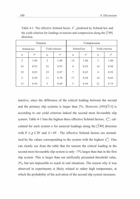
4 Discussion
100
inactive, since the difference of the critical loading between the second
and the primary slip systems is larger than 2%. However, (101)[111] is
according to our yield criterion indeed the second most favourable slip
system. Table 4-1 lists the highest three effective Schmid factors, */t cατ , cal-
culated for each system for uniaxial loadings along the [149] direction
with 0 20χ≤ ≤o o and 45λ ≈ o . The effective Schmid factors are normal-
ized by the values corresponding to the system with the highest */t cατ . One
can clearly see from the table that for tension the critical loading in the
second most favourable slip system is only ~7% larger than that in the first
slip system. This is larger than our artificially presumed threshold value,
2%, but not impossible to reach in real situations. The reason why it was
observed in experiments is likely related to rather high temperature, at
which the probability of the activation of the second slip system increases.
Table 4-1. The effective Schmid factor, *τ , predicted by Schmid law and the yield criterion for loadings in tension and compression along the [149] direction.
5
11
19
16
2
0.690.5015
0.700.585
0.870.6519
0.930.9316
1.001.002
21
18
4
14
3
0.750.503
0.850.5817
0.930.657
0.960.934
1.001.0014
Tension
Schmid law Yield criterion
Compression
Schmid law Yield criterion
α α α ατ* τ* τ* τ*

4.2 Yielding of the single crystal by yield criterion
101
The map of the most operative slip systems for compressive loadings pre-
dicted by the Schmid law [Fig. 4-4(c)] is identical to that for tensile load-
ings, only the predicted slip systems for the two loading orientations are
conjugate to each other (see Table 3-1). This is because the only differ-
ence between tension and compression is that the sense of the shear stress
parallel to the slip direction is reversed, so that (101)[111] ( = 2) for ten-
sion corresponds to (101)[111] ( = 14) for compression. In contrast to
tension, the predictions of the yield criterion for compression [Fig. 4-4(d)]
vary considerably with the orientation of the loading axis and are overall
much more complex than those of the Schmid law. The most striking dif-
ference is that our yield criterion predicts completely different primary
slip system ( = 3) than the Schmid law ( = 14). As found in the atomis-
tic simulations, this result is related to the strong effect of the shear stress
perpendicular to the slip direction, which causes the preferential activation
of the = 3 over the = 14 slip system, although the latter possesses a
much higher Schmid factor. Only close to the [011] corner, = 14 is pre-
dicted to be the primary slip system. The dislocation motion on slip sys-
tems other than (101)[111] is the well-known anomalous slip observed in
most bcc metals [44]. Unfortunately, to our knowledge there are currently
no experimental results from low temperature compression testings avail-
able to verify our theoretical predictions. However, our study shows the
ability of the yield criterion to predict a very complex mechanical behav-
iour for the iron single crystal under compression.

4 Discussion
102
4.2.2 Yield stress asymmetry in tension and compression
The tension-compression asymmetry in bcc metals was observed experi-
mentally [32, 34, 189-197] in both separate tension/compression tests and
successive tension-compression cycles for different loading orientations
and temperatures. In most orientations of the standard stereographic trian-
gle, the CRSS for compression was found to be higher than that for ten-
sion. This agrees with our atomistic results for iron presented in Chapter
3.1.1. It should be noted that since the tension-compression asymmetry is
related to intrinsic properties of screw dislocation, it is obvious at low
temperatures but usually becomes negligible as the temperature increases
(see later).
Koss concluded already in the 1980’s that the tension-compression asym-
metry is closely related to the twinning-antitwinning asymmetry [198].
However, based on our atomistic results and the analytical yield criterion,
it will show in the following that the tension-compression asymmetry is a
consequence of not only the twinning-antitwinning asymmetry but also
the strong effect of the shear stress perpendicular to the slip direction, via
the so-called strength differential (SD) factor:
( ) / 2t c
t c
SD σ σσ σ
−=−
(4-3)
where t and c are the uniaxial yield stresses in tension and compression,
respectively. For any orientation of the loading axis these yield stresses
can be determined from the yield criterion as described above. Performing
this calculation for all orientations of tension/compression axes, a map of
the strength differential can be obtained for the whole standard stereo-
graphic triangle. This is displayed in Fig. 4-5 by shading the interior of the

4.2 Yielding of the single crystal by yield criterion
103
standard triangle by the value of SD according to Eq. 4-3 (One should note
the comparison between loadings in tension and compression in the same
direction is regardless of slip systems).
The results drawn in Fig. 4-5(a) were obtained when only the twinning-
antitwinning asymmetry was considered by using the first two terms in
Eq. 3-3. The distribution of SD is in this case anti-symmetric with respect
to , and SD equals to zero for = 0. When is positive, the loadings in
Figure 4-5. Tension-compression asymmetry factor calculated with (a) only twinning-antitwinning asymmetry and (b) the full yield criterion.
(a)
(b)

4 Discussion
104
tension are in the anti-twinning sense while loadings in compression are in
the twinning sense. The value of SD is positive in this region and its max-
imum reaches about 0.4 at [111] corner. Vice versa, SD is negative for <
0 where the senses of the twining/anti-twinning are reversed. The mini-
mum value of SD is -0.4 corresponding to uniaxial loading along the [001]
direction.
Fig. 4-5(b) contains the SD map calculated with both the effects of the
twining-antitwinning asymmetry and the shear stress perpendicular to the
slip direction. It is clearly very different from the predictions made with
the twinning-antitwinning effect only. Comparing to Fig. 4-5(a), one of
the most prominent changes in Fig. 4-5(b) is that the region with positive
SD value is greatly reduced to the [011] corner. The complete yield crite-
rion predicts that for most orientations of the uniaxial loadings in the
standard stereographic triangle the yield stress for compression is larger
than that for tension and thus SD < 0. For loading axis close to the
[011] [111]− side, the critical stress for tension gradually increases rela-
tive to the critical stress for compression and then SD becomes positive.
The distribution of SD is no longer anti-symmetric with respect to = 0,
but the boundary is markedly shifted towards the [011] corner. The maxi-
mum positive tension-compression asymmetry lies at the [011] corner
with SD ~ 0.2, while the minimum value of the strength differential corre-
sponds to the loading axis along [001] where SD ~ -0.6.
In experiments, the tension-compression asymmetry in iron single crystal
was measured by Zwiesele and Diehl [17]. The sample was uniaxial de-
formed along the direction for which 11 12χ≤ ≤o o and ~ 0.72 (note is
an estimated value since the exact value of is not provided in Ref. [17]).
The critical resolved shear stresses at the lowest measured temperature of

4.3 Thermally activated dislocation mobility
105
77 K were ~240MPa for tension and ~280MPa for compression so that SD
is about -0.15. As seen in Fig. 4-5, the predicted SD values at 0 K for the
same loading orientation are +0.17 when only twinning-antitwinning
asymmetry is considered and -0.20 using the full yield criterion. The later
value agrees very well with the experimental result, and shows the ability
of the atomistically-based yield criterion to predict accurately the yield
behavior of Fe single crystal at low temperatures.
4.3 Thermally activated dislocation mobility
In Chapter 3.3 it developed a link between the behaviour of the a0/2<111>
screw dislocations in bcc iron at 0 K studied by static atomistic simula-
tions and the thermally activated dislocation motion at finite temperatures.
The commencement of the dislocation motion is regarded as nucleation
and subsequent propagation of kink-pairs that overcome the Peierls barrier
with the aid of thermal fluctuations and applied stress. In the line tension
model, the Peierls barrier is considered to be dependent on the applied
stress tensor and is a function of the MRSSP orientation of the loading and
both shear stress components parallel and perpendicular to the slip direc-
tion. This dependence has the same origin as that found for the Peierls
stress at 0 K by atomistic studies. The crucial connection between the 0 K
atomistic data and the thermally activated dislocation motion model is
achieved via the construction of the Peierls potential, whose derivative in
terms of the dislocation position (Eq. 3-17) gives the Peierls stress.

4 Discussion
106
The Peierls potential is constructed based on the m-function (Eq. 3-16),
which has the same symmetry as the {111} plane of the bcc lattice. The
height of the Peierls potential under zero stress, the twinning-antitwinning
asymmetry, and the dependence of the Peierls potential on the shear stress
perpendicular to the slip direction are described by parameter functions
multiplying the m-function. These functions are determined in a self-
consistent manner from the analytical yield criterion. The main advantage
of the constructed Peierls potential is that it reflects the dependence of the
Peierls stress on , and described in Chapter 4.1 and 4.2.
When comparing the stresses obtained by our calculations to those meas-
ured in experiments, one should note, deviations of the stresses between
the experimental data and the atomistic simulations exist for all bcc metals
regardless of the description scheme of the atomic interaction [34, 68, 92,
95, 98, 132, 184-187]. For example, the CRSS of the loading in tension
along the [149] direction for iron predicted at 0 K in Fig. 3-15 (or ob-
tained by atomistic studies in Chapter 3.1.2) is about 1800 MPa. In con-
trast, the critical resolved shear stress for approximately the same loading
orientation obtained by extrapolating low-temperature experimental meas-
urements of the yield stresses to 0K is between 340 MPa (loaded in ten-
sion with axis close to the [149] direction but small negative ,
8 6χ− ≤ ≤ −o o ) and 390 MPa (loaded in tension with axis close to the
[149] direction but small positive , 0 8χ≤ ≤o o ) [70]. Hence, the experi-
mentally estimated critical resolved shear stress is ~1/5 of the Peierls
stress obtained by the atomistic studies with the similar loading orientation
using BOP at 0 K.
Possible explanations that have been discussed in literature are following:
(1) a quantum mechanical tunnelling at low temperatures that aids the dis-

4.3 Thermally activated dislocation mobility
107
location to overcome the Peierls barrier [199-202]; (2) a quantum effect on
the vibration mode of the dislocation due to discrete energy levels and the
zero-point vibration [203-206]; (3) dynamical effects during dislocation
motion caused by finite velocity of dislocations, i.e. dislocation inertia
[207, 208]; (4) collective effects where a group of dislocations consisting
of both non-screws and screws can move at lower applied stress due to
mutual interactions [187]. All these effects may contribute to lowering the
CRSS at 0 K, thus when comparing the stresses obtained by our calcula-
tions to those measured in experiments, it is necessary to reduce the theo-
retical results by a rescaling factor of ~1/5, with which the predicted * at
0 K, where the required activation enthalpy vanishes, equals to the 0 K
yield stress estimated from experiments.
4.3.1 Temperature dependence of the yield stress
The knowledge of the Peierls potential enables us to describe the thermal-
ly activated dislocation motion via formation of kink-pairs using standard
dislocation models [52, 120-124].
In Chapter 3.3.2 the stress dependence of the activation enthalpy was ex-
emplified for loadings in tension along the [149] direction (see Fig. 3-15).
With the determined activation enthalpy, the temperature dependence of
the yield stress * for a given slip system at a fixed plastic strain rate γ&
can be expressed as [122-124]:
0( ) ln( )BH k T γσγ
=&
& (4-4)

4 Discussion
108
where H( ) is a function of the applied stress. With fixed plastic strain rate
γ& , the factor 0γ& can be determined from the temperature Tk at which the
thermal component of the yield stress vanishes. At this temperature the
activation enthalpy is equal to 2Hk, and thus the prefactor can be obtained
from:
0ln( ) 2 /k B kH k Tγγ
=&
& (4-5)
With fixed strain rate, the prefactor may vary with both temperature and
stress. However, in certain temperature interval it can be considered as a
constant virtually independent of stress and temperature [69, 72, 119].
This approximation is kept also in all our calculations and a constant
prefactor is used for a fixed strain rate as in [138].
Experimentally, the temperature dependence of the yield stress in iron sin-
gle crystal loaded in tension along the axis close to the [149] direction
was measured between 4 and 350 K by Brunner and Diehl [69, 70, 209]
(See Fig. 4-6). The loading orientation is characterized by 0 8χ≤ ≤o o and
43 45λ≤ ≤o o with ~ 0.51. The plastic strain rate was γ& = 8.5×10⁻⁴ s-1
and the temperature Tk at which the thermal component of the yield stress
vanished was approximately 350 K. The corresponding value of the
prefactor 0ln( / )γ γ& & is then ~30 (see [72, 118, 119]). Fig. 4-6 also includes
results of Kuramoto et al. [68, 210] for a high purity iron sample deformed
in a similar temperature range (4.2 to 300 K) in tension along axis close to
the [149] direction with = 0 and 45λ ≈ o . The strain rate in this study
was γ& = 1.7×10⁻⁴ s-1 which is also similar to the strain rate used in [69, 70,
209]. The corresponding prefactor 0ln( / )γ γ& & of ~27 agrees well with the

4.3 Thermally activated dislocation mobility
109
value obtained in studies of Brunner and Diehl. Based on these experi-
mental data, for our calculations it takes 0ln( / )γ γ& & = 30.
Fig. 4-6 is the comparison between the experimental results and our calcu-
lations. As mentioned previously the calculated stresses are rescaled by a
factor of ~1/5. The dashed blue curve corresponds to our prediction based
on the line tension model at low temperatures. It can be seen in this region
obvious differences existing between the prediction and the experimental
data. However one should note that the Peierls barrier V( ) (Eq. 3-25) de-
rived from the m-function has a sharp maximum due to its sinusoidal
character. It has been shown in [117, 178-182] that a better agreement be-
Figure 4-6. Temperature dependence of the yield stress in iron single crystal for loading in tension along the [149] direction predicted at high temperatures by the elastic interaction model (red curve), at low temperatures by the line tension model using Peierls potential with flat top (solid blue curve) and without flat top (dashed blue curve), and their comparisons to the experimental data [68-70, 209, 210] (sym-bols). One should note the calculated shear stresses are rescaled by a factor of ~1/5.
0 100 200 300 400T (K)
0
100
200
300
400
σ (M
Pa)
Exp. BrunnerExp. KuramotoEI modelLT modelLT model (NFT)
IIIIII

4 Discussion
110
tween calculated temperature dependence of the yield stress and the exper-
imental data is obtained if the Peierls barrier is flat, i.e. the MEP has a flat
plateau instead of the sharp maximum. Mathematically, a truncating of the
m-function producing the flat plateau, the so-called “flat top”, can be ob-
tained [138] by using a flatting operator f̂ . The important feature of the
operator f̂ is that it is only applied to every saddle point, i.e. only the
sharp maximum of the MEP are removed while the positions and heights
of the minima and maxima of m remain unaffected. In the current work, a
simplified f̂ operator which imposes a sharp flatting on the top of the
MEP is probed in the following way:
( ) if f fV V V Vξ = > (4-6)
so that if the energy along the MEP is higher than fV , it will be set to a
constant value fV . This simple truncating scheme makes the Peierls bar-
rier flat with the critical value fV determined by:
1 2( ) ( )2f
V VV ξ ξ+= (4-7)
where
1 max
2 max
( )( )VV
ξ ξ ξξ ξ ξ
= − Δ= + Δ
(4-8)
and
max[ ( ) ]cV uξ ξ ξΔ = − ⋅ (4-9)
in which max( )Vξ and cξ are the positions of the dislocation on the transi-
tion path with maximum energy and maximum force respectively. The
variable u in Eq. 4-9 is the only parameter determining the position of the
flat top. The choice of u is not unique. The basic requirements for its se-

4.3 Thermally activated dislocation mobility
111
lection are that, firstly, fV must be higher than ( )cV ξ and consequently
the reasonable value of u is between 0 and 1, and, secondly, the modified
MEP should give a better temperature dependence of stress than that with-
out the flat top.
Fig. 4-7 shows the Peierls barrier with the flat top with u equal to 0.65,
which was found to be the best choice for Fe. However it is important to
emphasize here that the m-function (Eq. 3-16) is just an empirical and
therefore possibly crude representation of the shape of the Peierls barrier.
The flat-top approximation is based on empirical fitting rather and does
not have any solid physical background. A better way to obtain the shape
of the Peierls barrier is to determine the MEP directly by means of atomis-
tic calculation using the NEB method to follow the dislocation crossing
the barrier. This work is still in progress.
The solid blue curve in Fig. 4-6 based upon the line tension model with
flat-topped Peierls potential shows us the temperature dependence of the
Figure 4-7. The original Peierls barrier V( ) without flat top by m-function (dashed curve) and the modified one with flat plateau (solid curve) by the flatting operation in Eq. 4-6.
fV
maxV
[Å]
()
Vξ
cξξ

4 Discussion
112
yield stress of iron at low temperatures. Comparing to the dashed blue
curve, it shows that with the flat-top approximation our predictions
matches better the experimental data. In this region, the straight disloca-
tion is first shifted away from its minimum position in the Peierls potential
by the applied stress and then bows out by thermal fluctuations. When
enough energy is provided, the bow-out reaches the critical configuration
and continues to expand as a fully developed kink-pair. The activation
process depends on the stress components both parallel and perpendicular
to the slip direction.
With increasing temperature and decreasing *, the influence of the stress
on the shape of the Peierls potential vanishes and the controlling mecha-
nism of the kink-pair formation gradually changes from the line tension
model at low temperatures to the elastic interaction model at high tem-
peratures.
For the latter mechanism the fully developed kink pairs are formed by
thermal fluctuations. Once enough energy is gained to overcome the ener-
gy barrier, the kinks propagate and consequently the screw dislocation
moves. This process is determined only by the shear stress component *.
The curves describing the two models intersect at T ~ 250 K and stress
~50 MPa, where the activation enthalpies of both models become equal.
In the high temperature region, the yield stress * continues to decrease
with increasing temperature until it vanishes at T ~ 350 K. Above this
temperature only the constant athermal stress σ is sufficient to move the
dislocations.

4.3 Thermally activated dislocation mobility
113
4.3.2 Temperature dependence of the twinning-antitwinning asymmetry
The general formulation of the Peierls potential developed above provides
also a natural description of the twinning-antitwinning asymmetry at finite
temperatures. The dependence of the yield stress on the orientation of the
Figure 4-8. Temperature dependences of the twinning-antitwinning asymmetry in iron single crystal predicted by the line tension model (curves) at low temperatures and their comparisons to the experimental data [69, 70] (symbols), by loadings in tension along three orientations with 18 22χ≤ ≤o o (LP), 0 8χ≤ ≤o o (SP), 8 6χ− ≤ ≤ −o o (SN) and the same value. One should note the calculated shear stresses are rescaled by a factor of ~1/5.
0 20 40 60 80 100 120T (K)
100
150
200
250
300
350
400
σ (M
Pa)
LPSNSP
χ = 0λ = 45
οο

4 Discussion
114
MRSSP at different temperatures can be compared directly to available
experimental results.
The twinning-antitwinning asymmetry in iron single crystal loaded in ten-
sion was experimentally measured between 4 and 110 K by Brunner and
Diehl [69, 70] (See Fig. 4-8). Three different angles between the primary
slip plane (101) and the MRSSP were selected, namely 18 22χ≤ ≤o o ,
0 8χ≤ ≤o o and 8 6χ− ≤ ≤ −o o for samples marked as large positive (LP),
small positive (SP), and small negative (SN), respectively. For all sam-
ples, the angle between the tension direction and the [111] slip direction
was 43 45λ≤ ≤o o , which corresponds to ~ 0.51. The plastic strain rate
was γ& = 8.5×10⁻⁴ s-1 and the corresponding value of the prefactor was
0ln( / )γ γ& & =30 [119].
Calculations with the same loading orientations as those in the above ex-
periments are performed. The curves in Fig. 4-8 are our predictions based
on the line tension model at low temperatures (One should note the calcu-
lated stresses are rescaled by a factor of ~1/5). We see that in the whole
temperature range the yield stress with positive is higher than that with
negative at the same temperature, while the values for = 0 lie inbe-
tween. This agrees with our atomistic simulations shown in Fig. 3-3 in
Chapter 3.1.1 where the same twinning-antitwinning tendency was ob-
tained at 0 K.
The result also shows an excellent agreement between our predictions and
the experimental data, which demonstrates the ability of our model to pre-
dict accurately the twinning-antitwinning asymmetry. In addition, it can be
seen from both the experimental data and our theoretical predictions that
the twinning-antitwinning asymmetry decreases with increasing tempera-

4.3 Thermally activated dislocation mobility
115
ture. The magnitude of the twinning-antitwinning asymmetry is therefore
inversely proportional to T in this temperature region. It can be expected
that the twinning-antitwinning asymmetry vanishes when the controlling
mechanism of the kink-pair formation changes from the low temperature
model to the high temperature model at ~250K where the mechanism of
fully developed kink-pair becomes applicable. Above this temperature, the
energy barrier does not change significantly during the loading, and the
activation enthalpy becomes only a function of the shear stress * project-
ed on the slip plane (Eq. 1-4).
4.3.3 Temperature dependence of the tension-compression asymmetry
Similar to the twinning-antitwinning asymmetry, the tension-compression
asymmetry is usually obvious at low temperatures but negligible at room
temperature [44]. For example, the tension-compression asymmetry was
observed to decrease smoothly with increasing temperature for a loading
orientation in the center of the stereographic triangle in single crystal nio-
bium despite a transition in the slip behaviour [197].
The tension-compression asymmetry in iron single crystal was measured
at temperatures between 77 and 410 K by Zwiesele and Diehl [17] (See
Fig. 4-9). The sample was uniaxial deformed along the direction for which
11 12χ≤ ≤o o and ~ 0.72 ( is an estimated value since the exact value of
was not provided in Ref. [17]). The plastic strain rate was γ& = 5.6×10⁻⁴
s-1 and the corresponding prefactor 0ln( / )γ γ& & = 29±1. In this temperature
range, the experimentally observed glide system for both tension and
compression is the (101)[111] slip system. Recalling Fig. 4-4(d) in Chap-

4 Discussion
116
ter 4.2.1, the predicted slip system for compression with the same loading
orientation at 0 K is however (110)[111] . The explanation of this discrep-
ancy lies in an increasing probability for the activation of the (101)[111]
slip system, which possesses the second lowest critical loading stress at 0
K (Table 4-1), with increasing temperature. Such temperature dependent
slip behaviour will be discussed in detail in the next section.
Fig. 4-9 presents our theoretical predictions, with a rescaling factor of
~1/5 for the calculated stresses, and their comparison with the experi-
mental data. It is seen that the model reproduces closely the experimental
Figure 4-9. Temperature dependence of tension-compression asym-metry in iron single crystal predicted by the line tension model (curves) at low temperatures and its comparison to the experimental data [17] (symbols), by loadings in tension and compression along orientation with 11 12χ≤ ≤o o and ~ 0.72. One should note the cal-culated shear stresses are rescaled by a factor of ~1/5.
0 100 200 300T (K)
0
50
100
150
200
250
300
350σ
(MPa
)tensioncompression
χ = 0λ = 45
οο

4.3 Thermally activated dislocation mobility
117
results, and predicts a significant tension-compression asymmetry mainly
at low temperatures. The magnitude of the difference decreases with in-
creasing temperature or decreasing *, and vanishes at T > 250K, at which
the saddle-point configuration for the formation of kink-pairs changes
from the bow-out to a pair of fully formed kinks. As already discussed in
Chapter 4.2.2, the tension-compression asymmetry is the consequence of
the twinning-antitwinning asymmetry and the effect of the shear stress
perpendicular to the slip direction [101, 109]. With increasing tempera-
ture, both effects diminish and, consequently, also the tension-
compression asymmetry decreases until it vanishes completely.
The tension-compression asymmetry predicted by our model shows again
a very good agreement with the experimental data. It indicates that the
constructed two-dimensional Peierls potential is capable of describing the
temperature dependence behaviour originating from the shear stresses
perpendicular to the slip direction, which is one of the most important fac-
tors distinguishing bcc and close-packed metals.
4.3.4 Temperature dependence of the slip system
We have illustrated in Chapter 3.2.3 that one can predict the glide of screw
dislocations at 0 K on all 24 slip systems in bcc Fe single crystal. The dis-
location may glide on the slip plane with lower Schmid factor, owing to
the shear stress perpendicular to the slip direction. However, as shown in
the previous section, this effect decreases with increasing temperature.
This indicates that the anomalous slip at low temperatures can be replaced
by the normal slip on the glide plane with higher Schmid factor at high
temperatures. Thus, when the temperature is taken into account, the yield

4 Discussion
118
criterion of Eq. 3-3 in terms of stress only is no longer adequate to deter-
mine the slip behaviour of the a0/2<111> dislocations in bcc iron. In the
current section it will show in detail how the slip system varies with tem-
perature.
At finite temperatures, the yielding occurs firstly on the slip system with
the lowest activation enthalpy. Since the Peierls potential V (x,y) depends
strongly on the loading orientation, its variations are not the same for dif-
ferent slip systems characterized by a unique set of values ( αχ , ασ , ατ ).
Consequently, also the dependencies of the activation enthalpies on the
Figure 4-10. Temperature dependence of the activated slip system for loadings in compression along the [149] direction in iron single crystal. The temperature dependences of the critical yield stress for the a0/2[111] screw dislocation were predicted by the line tension model on three {110} slip planes of the [111] zone. One should note the calculated shear stresses are rescaled by a factor of ~1/5.
0 50 100 150 200 250 300T (K)
0
200
400
600
800
1000σ
(MPa
)
[110][101][011]
χ = 0λ = 45
οο
0.0ΔH (eV)
0.2 0.4 0.6 0.8

4.3 Thermally activated dislocation mobility
119
applied loading can be different, and therefore different slip systems with
the lowest activation enthalpy may be activated as temperature changes.
An illustrative example of such behaviour is the loading in compression
along the [149] direction. Table 4-1 in Section 4.2.1 listed the three larg-
est effective Schmid factors */t cατ among all possible slip systems. One can
see that at 0 K the critical loading for the second most favourable slip sys-
tem, (101)[111] ( = 14), is only ~4% larger than that for the primary slip
system, (110)[111] ( = 3).
Fig. 4-10 shows the temperature dependences of the CRSS for compres-
sion along the [149] direction ( = 0 and = -0.5) for the screw disloca-
tion with a0/2[111] Burgers vector on the three glide planes in the [111]
zone. To consistent with previous discussion, the calculated stresses are
again rescaled by a factor of ~1/5.
At very low temperatures close to 0 K, the primary slip system is indeed
(110)[111] ( = 3) as predicted by our yield criterion [cf. Fig. 4-4(d)] .
However, as the temperature increases to ~40K, the slip plane with the
lowest critical stress changes from (110)[111] ( = 3) to (101)[111] (
= 14). This change of the primary slip system helps to resolve the apparent
disagreement between our theoretical predictions based on the yield crite-
rion and the experimental observations. As already mentioned, Zwiesele
and Diehl [17] found that the slip above 77 K indeed occurs on
(101)[111] ( = 14) and not on (110)[111] ( = 3) for both tension and
compression, in perfect agreement with results shown in Fig. 4-10. As dis-
cussed in Chapter 4.2.1, similar discrepancies, where the experimentally
observed slip system is the one with the second lowest critical yield stress,
exist for other tensile loadings. The explanation of these apparent discrep-

4 Discussion
120
ancies is likely equivalent to that presented here. The predictions in Fig. 4-
4 are based on the yield criterion developed for 0 K, while experimental
observations are always performed at finite temperatures. As the tempera-
ture increases, the effect of the shear stress perpendicular to the slip direc-
tion decreases and the slip changes from the anomalous slip plane to the
normal slip plane, which has usually a higher Schmid factor than the for-
mer. It is therefore necessary to consider the effect of temperature when
comparing the theoretical predictions with experiments as changes of the
slip systems with temperature have been observed frequently in bcc metals
[44, 68, 188]. If the activation enthalpies for two slip systems are similar
(for instance, in the vicinity of the crossing of the curves in Fig. 4-10),
both of these slip systems can be activated at the same time. In this case,
the macroscopically observed slip plane could be a {211} plane or any
high index plane in the zone of the [111] slip direction.
Figure 4-11. Zig-zag slip (green lines) of the a0/2[111] screw dislocation glide macroscopically on a high-index slip plane (red) in the [111] zone under compression.
(101)
(110)
(011)
χ[111]
MRSSP
ψ
1nv
0nv
1−n v

4.3 Thermally activated dislocation mobility
121
Finally, the total plastic strain rate can be determined by summation of
contributions of dislocations on all possible glide planes (cf. Eq. 3-29).
Thus for the a0/2[111] dislocation, the total velocity can be written as:
1 1 0 0 1 1− −= + +v v n v n v nv v v (4-10)
where inv are the unit vectors of the three glide planes in the [111] zone
(Fig. 4-11) and iv are the corresponding velocities:
0B
exp[ ]ii
Hvk TΔ= −v (4-11)
Eq. 4-10 enables us to determine the dependence of the angle between
the (101) plane and the macroscopic slip plane as a function of tempera-
ture. This dependence is plotted in Fig. 4-12.
At temperatures below 25 K, the dislocation velocity in Eq. 4-10 is entire-
ly determined by 1−v along the (110) plane of the lowest activation en-
thalpy 1H−Δ so that 60ψ = − o . Since the activation enthalpy appears in Eq.
4-11 in exponent, the contribution from the other two slip systems with
higher iHΔ can be safely neglected (see Fig. 4-10).
In the transition region between 25 and 40 K the (110) plane possesses
still the lowest activation enthalpy, but the difference between the (110)
and (101) planes becomes smaller. Both contributions need to be included
and consequently ψ starts increasingly deviating from 60− o . The critical
point where the activation enthalpies for the (110) and (101) planes be-
come equal occurs at T ~ 40K. At this temperature both planes are equally
active and the macroscopic slip plane is the (211) plane.
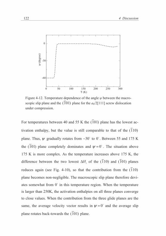
4 Discussion
122
For temperatures between 40 and 55 K the (101) plane has the lowest ac-
tivation enthalpy, but the value is still comparable to that of the (110)
plane. Thus, ψ gradually rotates from 30− o to 0o . Between 55 and 175 K
the (101) plane completely dominates and 0ψ = o . The situation above
175 K is more complex. As the temperature increases above 175 K, the
difference between the two lowest iHΔ of the (110) and (101) planes
reduces again (see Fig. 4-10), so that the contribution from the (110)
plane becomes non-negligible. The macroscopic slip plane therefore devi-
ates somewhat from 0o in this temperature region. When the temperature
is larger than 250K, the activation enthalpies on all three planes converge
to close values. When the contribution from the three glide planes are the
same, the average velocity vector results in 0ψ = o and the average slip
plane rotates back-towards the (101) plane.
Figure 4-12. Temperature dependence of the angle between the macro-scopic slip plane and the (101) plane for the a0/2[111] screw dislocation under compression.
0 50 100 150 200 250 300T (K)
-60
-30
0ψ
(deg
ree)

4.3 Thermally activated dislocation mobility
123
Fig. 4-12 reveals that the macroscopic slip plane can vary considerably
depending on the loading orientation and temperature. According to the
Schmid law, the slip of the a0/2[111] screw dislocation should always oc-
cur on the plane with the highest resolved shear stress, i.e. the (101) plane.
However, our predictions show the possible occurrence of the anomalous
slip [44, 77, 78] at low temperatures. As the temperature increases, the
effect of the perpendicular shear stress is reduced, and the Schmid factor
gradually dominates. Consequently, the macroscopic slip plane rotates
from the anomalous (110) slip plane to the normal (101) slip plane. The
slip behaviour of real single or polycrystalline materials at finite tempera-
tures can be still much more complex, since dislocations with other Burg-
ers vector can be also involved.


5 Summary and outlooks
The main goal of this thesis was to study the properties of the a0/2<111>
screw dislocations in bcc -iron, and to establish a link between the mi-
croscopic behavior of these defects and the macroscopic plasticity.
It started with investigation of the dislocation core structure by means of
static atomistic simulations. The inter-atomic interactions were described
by the recently developed magnetic bond-order potential [100] that is able
to describe correctly both the angular character of bonding and the mag-
netic interactions in iron. Despite its quantum mechanical origin, BOP is
not limited by the periodic boundary conditions and is sufficiently compu-
tationally efficient for the modeling of dislocations. The core structure of
the a0/2<111> screw dislocation with this magnetic BOP was found to be
non-degenerate and invariant with respect to both the [111] threefold axis
and the [101] diad. This is the core structure found in all DFT calculations
for bcc metals [93-97], in contrast to the degenerate core structures ob-
tained by most empirical potentials [54, 84-87]. BOP is also able to pre-
dict the Peierls barrier for screw dislocation moving between two neigh-
boring stable sites in quantitative agreement with DFT calculations [157]
as well as experimental estimations [158] (Fig. 2-1).
In the next step, the focus is on the behavior of the 1 2[111] screw disloca-
tion under externally applied stress. In Chapter 3.1 it studied loadings by

5 Summary and outlooks
126
pure shear stress parallel to the slip direction. The loadings were applied
on different MRSSP defined by the angle between the MRSSP and the
(101) plane. The dependence of the CRSS on in Fig. 3-3 shows the de-
viation of the CRSS between the atomistically obtained data and the pre-
dictions from the Schmid law. This twinning-antitwinning asymmetry was
observed in experiments (see for example [44, 68]). For all loadings with
pure shear stress parallel to the slip direction the slip is always observed to
be on the (101) glide plane which has the highest Schmid factor within
30 30χ− ≤ ≤o o . It is also the glide plane for the 1 2[111] screw dislocation
in molybdenum and tungsten under the same loadings [101].
Beside the pure shear stresses, the uniaxial loadings in both tension and
compression were performed. Our results show that the CRSS for tension
is always lower than that for compression in the same loading direction,
and that the CRSS for pure shear with the same MRSSP lies in between of
the two. This so-called tension-compression asymmetry observed in ex-
periments is a consequence of the non-planar core structure. The origins of
the tension-compression asymmetry were analyzed by further calculations
in which a special stress tensor (Eq. 4-1) with only shear stresses perpen-
dicular to the slip direction was applied. The differential displacement
plots in Fig. 4-2 show that although it does not drive directly the screw
dislocation to move, the shear stress perpendicular to the slip direction
changes the symmetry of the core and makes the dislocation either easier
or harder to slip on different {110} planes in the <111> zone. The out-
come of our static atomistic simulations showed that the complex depend-
ence of the CRSS is governed by three factors, namely, the Schmid factor,
the shear stress perpendicular to the slip direction, and the twinning- an-
titwinning asymmetry.

5 Summary and outlooks
127
Based on the atomistic results, a description of the macroscopic yielding
of single crystals containing a0/2<111> screw dislocations with all possi-
ble Burgers vectors was formulated in terms of an analytical yield criteri-
on. The motion of the screw dislocations is considered to be triggered
once the external loading satisfies the yield criterion in any of the 24 slip
systems. In order to capture the dependences of the CRSS on both the
MRSSP orientation and the non-Schmid stress components, a linear com-
bination of two shear stresses parallel to and two shear stresses perpendic-
ular to the slip direction, both resolved in two different {110} planes of
the [111] zone, was used to construct the analytical yield criterion (Eq. 3-
3), following the studies in [109]. The obtained yield criterion was shown
to reproduce closely the atomistic data for not only the CRSS of the glide
on the primary (101) plane but also that of the anomalous slip on the other
{110} planes. In addition, the yield criterion was used to obtain the yield
polygon, which is the yielding surface projected on the CRSS- graph for
a given MRSSP. This yield polygon shows a more complex deformation
behavior carried by the a0/2<111> screw dislocations in single crystal iron
than yield polygon derived from the Schmid law.
A convenient tensorial representation of the yield criterion was then uti-
lized to determine the first activated slip systems under a given uniaxial
loading for all orientations in the stereographic triangle. The results pre-
sented in Fig. 4-4 show that the primary slip system for most tensile load-
ings is the (101)[111] slip system, which possesses the highest Schmid
factor. Possible secondary slip systems exist only in the vicinity of the
[001] [111]− and [001] [011]− borders of the stereographic triangle. The
theoretical predictions agree with available experiments [68]. While the
predictions for tension are similar to those of the Schmid law, the slip sys-

5 Summary and outlooks
128
tems for compressions determined using the yield criterion are much more
complex than those using Schmid law. Most striking is the prediction of
different primary slip systems in the central region of the stereographic
triangle, which is clearly a consequence of the strong effect of the shear
stress perpendicular to the slip direction. Furthermore, the first activated
slip system varies considerably with the orientation of the loading axis,
showing a large complexity of the deformation behavior of iron single
crystals in compression.
Based on the calculations above, the tension-compression asymmetry is
analyzed for all orientations of the loading axis in the stereographic trian-
gle using the strength differential. It showed that the tension-compression
behavior originates mainly due to the effect of the shear stress perpendicu-
lar to the slip direction. Our results again agree well with experiments ac-
cording to which in most regions of the stereographic triangle the critical
loading for compression is higher than that for tension [44].
The third main topic of the thesis was to develop a link between the glide
of the a0/2<111> screw dislocations in bcc iron at 0 K studied by the static
atomistic simulations and the thermally activated glide of dislocations at
finite temperatures. For the latter the commencement of the dislocation
motion is regarded as a nucleation and subsequent propagation of kink-
pairs, which overcome the Peierls barrier under the effect of the applied
stress and the aid of thermal fluctuations. The Peierls barrier is considered
to be dependent on the applied stress tensor and is a function of the
MRSSP orientation of the loading and both shear stress components paral-
lel and perpendicular to the slip direction. This dependence has the same
origin as that found for the Peierls stress in the atomistic studies for a sin-
gle a0/2<111>{110} dislocation. The connection between them is that the

5 Summary and outlooks
129
Peierls stress along the glide plane should equal to the derivative of the
Peierls potential in terms of the dislocation position.
The Peierls potential was constructed based on the m-function [137, 138],
which satisfies the symmetry of the {111} plane in the bcc lattice. The
heights of the Peierls potential under zero stress as well as its changes un-
der general applied stress were described by parameter functions multiply-
ing the m-function. These parameter functions were determined in a self-
consistent manner using the yield criterion. In this way, the Peierls poten-
tial inherited all the properties of the yield criterion i.e., its dependences
on the Schmid factor, the twinning-antitwinning asymmetry, and the shear
stress perpendicular to the slip direction.
Using the atomistically consistent Peierls potential, the thermally activated
dislocation motion via formation of kink-pairs is treated using standard
dislocation models [52, 120-124]. The application of these models leads to
a correct description of the temperature dependence of the yield stress.
The dependence of the twinning-antitwinning asymmetry on temperature
is also predicted successfully, and compares well with the experimental
data for three loading orientations in tension with different but the same
value (Fig. 4-8). The twinning-antitwinning asymmetry decreases with
increasing temperature, and is expected to vanish when the activation
model changes from the bow-out mechanism (line tension model) to the
fully formed kink-pairs (elastic interaction model). There is also an excel-
lent agreement between our predictions and experimental results [17] for
the tension-compression asymmetry. Similar to the twinning-antitwinning
asymmetry, the predicted magnitude of the tension-compression asym-
metry also decreases with increasing temperature since the activation en-
thalpies for tension and compression converge. This occurs when the

5 Summary and outlooks
130
kink-pair formation mechanism changes from the low temperature model
to the high temperature model at which fully developed kink pairs domi-
nate.
It has been mentioned that the experimentally observed slip system for
loading in compression along the direction studied in [17] is the
(101)[111] slip system, which is different to the predicted slip systems for
the same loading orientation at 0 K using the yield criterion (Fig. 4-4).
The reason is that the predictions in Fig. 4-4 are based on the yield criteri-
on which is developed for 0K while experiments are performed at finite
temperatures. When considering the single crystal with dislocations of all
possible Burgers vectors, the yielding happens on the slip system with the
lowest activation enthalpy. Since the activation enthalpy varies with tem-
perature, the slip system may also change. For the compression along the
[149] direction, the predicted slip system at low temperatures close to 0 K
is (110)[111] . However, as temperature increases to ~40 K, the slip sys-
tem changes to (101)[111] , in good agreement with experimental observa-
tions.
As mentioned above, it is necessary to apply a scaling factor of 1/5 when
comparing the CRSS obtained from our atomistic calculations to that es-
timated from low-temperature experimental measurements of the yield
and flow stresses by extrapolating to 0 K. This discrepancy between the
experimental and atomistic results exists for all bcc metals regardless the
description of the atomic interaction [34, 68, 92, 95, 98, 132, 184-187]. A
satisfactory explanation is still lacking. However, since this constant factor
only rescales the absolute CRSS values, it should not alter any of the qual-
itative results presented here.

5 Summary and outlooks
131
Finally, the author believes this work reached the goal to describe the plas-
tic deformation behavior of iron single crystal at finite temperatures based
on the microscopic properties of the screw dislocations. However, since
the atomistic simulations of dislocation are limited by short accessible
length and time scales, there is still room for other modeling schemes.
Probably the most natural mesoscopic approach is the Discrete Disloca-
tion Dynamics (DDD) that is able to follow evolution of dislocation en-
sembles based upon the single dislocation mobility laws to study the mac-
roscopic deformation behavior in metals in real time. The dislocation mo-
bility laws in DDD models is currently based almost exclusively on the
Kocks law [120, 139], which describes the activation enthalpy as a func-
tion of the resolved shear stress by fitting the parameters to experimental
results. This mobility law does not reflect the non-Schmid effects, e.g., the
twinning-antitwinning and tension-compression asymmetries observed in
both experiments and atomistic studies. In the current work, it established
a bottom-up model which can deliver information about dislocation mo-
bilities directly from the microscopic level. The results obtained in this
work therefore can be utilized in the future as input data in higher level
modeling schemes such as DDD simulations.


References
1. Schmid, E. Zn - normal stress law. in 1st International Congress for Applied Mechanics. 1924. Delft: Technische Boekhandel en Drukkerij J.Waltman Jr.
2. Schmid, E. and Boas, W., Kristallplastizität unter besonderer berücksichtigung der metalle. 1935, Berlin: Springer.
3. Seeger, A., in Encyclopedia of physics, Flugge, S., Editor 1958, Springer: Berlin. p. 1.
4. Taylor, G. I. and Elam, C. F., The distortion of iron crystals. Proc. Roy. Soc. Lond. A, 1926. 112: p. 337-361.
5. Taylor, G. I., The deformation of crystals of beta-brass. Proc. Roy. Soc. Lond. A, 1928. 118: p. 1-24.
6. Waseda, Y. and Isshiki, M., Purification process and characterization of ultra purity metals: Application of basic science to metallurgical processing. 2002, Berlin: Springer.
7. Cox, J. J., Horne, G. T., and Mehl, R. F., Slip, twinning and fracture in single crystals of iron. Trans. ASM, 1957. 49: p. 118-131.
8. Hull, D., Orientation and temperature dependence of plastic deformation processes in 3.25% silicon iron. Proc. R. Soc. Lond. A., 1963. 274: p. 5-20.
9. Matsui, H., et al., Mechanical properties of high purity iron. Trans. JIM, 1978. 19: p. 163-170.
10. Nine, H. D., Asymmetry of slip in fatigue of iron single crystals. Scr. Metall., 1970. 4: p. 887-891.
11. Šesták, B. and Zárubová, N., Asymmetry of slip in Fe-Si alloy single crystals. Phys. Stat. Sol. B, 1965. 10: p. 239-250.
12. Šesták, B., Zárubová, N., and Sladek, V., Slip planes in Fe-3 percent Si single crystals deformed at 77 degrees K. Can. J. Phys., 1967. 45: p. 1031.
13. Steijn, R. P. and Brick, R. M., Flow and fracture of single crystals of high purity ferrite. Trans. ASM, 1953. 46: p. 1406-1448.
14. Tadami Taoka, Shin Takeuchi, and Furubayashi, E., Slip systems and their critical shear stress in 3% silicon iron. J. Phys. Soc. Jpn., 1964. 19: p. 701-711.

References
134
15. Taoka, T., Takeuchi, S., and Furubayashi, E., Slip systems and their critical shear stress in 3% silicon iron. J. Phys. Soc. Jpn., 1964. 19: p. 701-711.
16. Tseng, D. and Tangri, K., Temperature and strain rate sensitivities of flow stress for the high purity AISI iron. Scr. Metall., 1977. 11: p. 719-723.
17. Zwiesele, S. and Diehl, J. Temperature and strain rate dependence of the macro yield stress of high purity iron single crystals. in 5-th Internat. Conf. Strength of Metals and Alloys. 1979. Pergamon Press.
18. Altshuler, T. L. and Christian, J. W., The mechanical properties of pure iron tested in compression over the temperature range 2 to 293 degrees K. Phil. Trans. R. Soc. Lond. A., 1967. 261: p. 253-287.
19. Takeuchi, S., Furubayashi, E., and Taoka, T., Orientation dependence of yield stress in 4.4% silicon iron single crystals. Acta Metall., 1967. 15: p. 1179-1191.
20. Tomalin, D. S. and McMahon Jr, C. J., On the plastic asymmetry in iron crystals. Acta Metall., 1973. 21: p. 1189-1193.
21. Zarubova, N. and Sestak, B., Plastic deformation of Fe-3% Si single crystals in the range from 113 to 473 K - 1. Thermally activated plastic flow. Phys. Status Solidi A, 1975. 30: p. 365-374.
22. Mitchell, T. E., Foxall, R. A., and Hirsch, P. B., Work-hardening in niobium single crystals. Philos. Mag., 1963. 8: p. 1895-1920.
23. Mitchell, T. E. and Spitzig, W. A., Three-stage hardening in tantalum single crystals. Acta Metall., 1965. 13: p. 1169-1179.
24. Bowen, D. K., Christian, J. W., and Taylor, G., Deformation properties of niobium single crystals. Can. J. Phys., 1967. 45: p. 903-938.
25. Foxall, R. A., Duesbery, M. S., and Hirsch, P. B., The deformation of niobium single crystals. Can. J. Phys., 1967. 45: p. 607-629.
26. Duesbery, M. S., The influence of core structure on dislocation mobility. Philos. Mag., 1969. 19: p. 501-526.
27. Duesbery, M. S. and Foxall, R. A., A detailed study of the deformation of high purity niobium single crystals. Phil. Mag. A, 1969. 20: p. 719-751.
28. Statham, C. D., Vesely, D., and Christian, J. W., Slip in single crystals of niobium-molybdenum alloys deformed in compression. Acta Metall., 1970. 18: p. 1243-1252.
29. Irwin, G. J., Guiu, F., and Pratt, P. L., Influence of orientation on slip and strain hardening of molybdenum single crystals. Phys. Status Solidi A, 1974. 22: p. 685-698.

References
135
30. Nawaz, M. H. A. and Mordike, B. L., Slip geometry of tantalum and tantalum alloys. Phys. Status Solidi A, 1975. 32: p. 449-458.
31. Nagakawa, J. and Meshii, M., Deformation of niobium single crystals at temperatures between 77 and 4. 2 K. Philos. Mag. A, 1981. 44: p. 1165-1191.
32. Hollang, L., Hommel, M., and Seeger, A., The flow stress of ultra-high-purity molybdenum single crystals. Phys. Status Solidi A, 1997. 160: p. 329-354.
33. Hollang, L. and Seeger, A., The flow-stress asymmetry of ultra-pure molybdenum single crystals. Mater. Trans. JIM, 2000. 41: p. 141.
34. Hollang, L., Brunner, D., and Seeger, A., Work hardening and flow stress of ultrapure molybdenum single crystals. Mater. Sci. Eng., A, 2001. 319-321: p. 233-236.
35. Lassila, D. H., Goldberg, A., and Becker, R., The effect of grain boundaries on the athermal stress of tantalum and tantalum-tungsten alloys. Metall. Mater. Trans. A, 2002. 33: p. 3457-3464.
36. Kirchner, H. O. K., Plastic deformation of the alkali metals sodium and potassium. Acta Phys. Austriaca, 1978. 48: p. 111-129.
37. Basinski, Z. S., Duesbery, M. S., and Murty, G. S., The orientation and temperature dependence of plastic flow in potassium. Acta Metall., 1981. 29: p. 801-807.
38. Siedersleben, M. E. and Taylor, G., Slip systems in bcc Li-Mg alloys. Philos. Mag. A, 1989. 60: p. 631-647.
39. Duesbery, M. S. and Basinski, Z. S., The flow stress of potassium. Acta Metall. Mater., 1993. 41: p. 643-647.
40. Pichl, W. and Krystian, M., The flow stress of high purity alkali metals. Phys. Status Solidi A, 1997. 160: p. 373-383.
41. Krystian, M. and Pichl, W., Investigation of the slip geometry of high-purity potassium by in situ x-ray diffraction. Mater. Sci. Eng., A, 2004. 387-389: p. 115-120.
42. Christian, J. W. and Vitek, V., Dislocations and stacking faults. Rep. Prog. Phys., 1970. 33: p. 307-411.
43. Kubin, L. P., Reviews on the deformation behavior of materials. Reviews on the deformation behavior of materials, 1982. 4: p. 181-275.
44. Christian, J., Some surprising features of the plastic deformation of body-centered cubic metals and alloys. Metall. Mater. Trans. A, 1983. 14: p. 1237-1256.
45. Taylor, G., Thermally-activated deformation of bcc metals and alloys. Prog. Mater Sci., 1992. 36: p. 29-61.
46. Seeger, A., J Phys IV, 1995. 5: p. 45-65.

References
136
47. Pichl, W., Slip geometry and plastic anisotropy of body-centered cubic metals. Phys. Status Solidi A, 2002. 189: p. 5-25.
48. Bassani, J. L., Plastic flow of crystals. Advances in Applied Mechanics, 1994. 30: p. 191-257.
49. Seeger, A., The temperature and strain-rate dependence of the flow stress of body-centred cubic metals: A theory based on kink-kink interactions. Z. Metallkde, 1981. 72: p. 369-380.
50. Suzuki, H., in Dislocation dynamics, Rosenfield, A. R., Editor 1968, Macgraw-Hill. p. 679.
51. Foxall, R. A. and Statham, C. D., Dislocation arrangements in deformed single crystals of niobium-molybdenum alloys and niobium-9% rhenium. Acta Metall., 1970. 18: p. 1147-1158.
52. Hirth, J. P. and Lothe, J., Theory of dislocations. 1982, New York: Wiley.
53. Duesbery, M. S., Dislocations in solids. 1989, Amsterdam: North-Holland.
54. Duesbery, M. S., The dislocation core and plasticity. Dislocations in Solids, 1989. 8: p. 67-173.
55. Yip, S., Handbook of materials modeling. 2005, New York: Spinger.
56. Vitek, V. and Paidar, V., in Dislocations in solids, Hirth, J. P., Editor 2008, Elsevier: Amsterdam. p. 439.
57. Allen, N. P., Hopkings, B. E., and Mclennan, L. E., The tensile properties of single crystals of high-purity iron at temperatures from 100 to -253 C. Proc. R. Soc. Lond. A., 1956. 234: p. 221-246.
58. Basinski, Z. S. and Christian, J., The influence of temperature and strain rate on the flow stress of annealed and decarburized iron at subatmospheric temperatures. Austr. J. Phys, 1960. 13: p. 299-308.
59. Conrad, H. and Schoeck, G., Cottrell locking and the flow stress in iron. Acta Mater., 1960. 8: p. 791-796.
60. Conte, R., Groh, P., and Escaig, B., Étude de l'écoulement plastique de monocristaux filamentaires de fer entre 300 et 4°k par. Phys. Status Solidi B., 1968. 28: p. 475-488.
61. Conrad, H. and Frederik, S., The effect of temperature and strain rate on the flow stress of iron. Acta Metal., 1962. 10: p. 1013-1020.
62. Stein, D. T., Low Jr., J. R., and Seybolt, A. U., The mechanical properties of iron single crystals containing less than 5×10E-3 ppm carbon. Acta Metall., 1963. 11: p. 1253-1262.
63. Stein, D. T. and Low Jr., J. R., Effects of orientation and carbon on the mechanical properties of iron single crystals. Acta Metall., 1966. 14: p. 1183-1194.

References
137
64. Arsenault, R. J., Low-temperature creep of alpha iron. Acta. Matall., 1964. 12: p. 547-554.
65. Keh, A. S. and Nakada, Y., Plasticity of iron single crystals. Canad. J. Phys., 1967. 45: p. 1101-1120.
66. Spitzig, W. A. and Keh, A. S., Orientation dependence of the strain-rate sensitivity and thermally activated flow in iron single crystals. Acta Metall., 1970. 18: p. 1021-1033.
67. Spitzig, W. A., Analysis of thermally-activated flow in iron single crystals. Acta Metall., 1970. 18: p. 1275-1284.
68. Aono, Y., Kuramoto, E., and Kitajima, K., Reports of research institute for applied mechanics, 1981, Kyushu University. p. 127-193.
69. Brunner, D. and Diehl, J., The use of stress-relaxation measurements for investigations on the flow-stress of alpha-iron. Phys. Status Solidi A, 1987. 104: p. 145-155.
70. Brunner, D. and Diehl, J., Extension of measurements of the tensile flow-stress of high-purity alpha-iron single-crystals to very low-temperatures. Zeitschrift Fur Metallkunde, 1992. 83: p. 828-834.
71. Seeger, A., in Dislocations, Veyssiere, P., Kubin, L., and Castaing, J., Editors. 1984, C.N.R.S.: Paris. p. 141.
72. Brunner, D. and Diehl, J., Temperature and strain-rate dependence of the tensile flow-stress of high-purity alpha-iron below 250-k .2. Stress temperature regime-II and its transitions to regime-I and regime-III. Phys. Status Solidi A, 1991. 125: p. 203-216.
73. Havner, K. S., Finite plastic deformation of crystalline solids, in Cambridge monographs on mechnics and applied mathematics, 1992, Cambridge University Press: Cambridge.
74. Gough, H. J., The behaviour of a single crystal of alpha-iron subjected to alternating torsional stresses. Proc. R. Soc. Lond. A, 1928. 118: p. 498-534.
75. Barrett, C. S., Ansel, G., and Mehl, R. F., Slip, twinning and cleavage in iron and silicon ferrite. Trans. Am. Soc. Met., 1937. 25: p. 702-733.
76. Chen, N. K. and Maddin, R., Slip planes and the energy of dislocations in a body centered cubic structure. Acta Metall., 1954. 2: p. 49-51.
77. Seeger, A., Why anomalous slip in body-centred cubid metals? Mat. Sci. Eng. A, 2001. A319-321: p. 254-260.
78. Seeger, A. and Wasserbaech, W., Anomalous slip - a feature of high-purity body-centred cubic metals. Phys. Stat. Sol. A, 2002. 189: p. 27-50.

References
138
79. Sigle, W., High-resolution electron microscopy and molecular dynamics study of the (a/2)[111] screw dislocation in molybdenum. Philos. Mag. A, 1999. 79: p. 1009-1020.
80. Mendis, B. G., et al., Use of the nye tensor in analyzing hrem images of bcc screw dislocations. Philos. Mag., 2006. 86: p. 4607-4640.
81. Vitek, V., Perrin, R. C., and Bowen, D. K., The core structure of 1/2(111) screw dislocations in bcc crystals. Phil. Mag., 1970. 21: p. 1049-1073.
82. Basinski, Z. S., Duesbery, M. S., and Taylor, R., Influence of shear stress on screw dislocations in a model sodium lattice. Can. J. Phys., 1971. 49.
83. Neumann, F., Vorlesungen über die theorie der elasticität 1885, Leipzig.
84. Vitek, V., Theory of the core structures of dislocations in body-centered-cubic metals. Cryst Lattice Defects, 1974. 5: p. 1-34.
85. Duesbery, M. S. and Richardson, G. Y., Dislocation core in crystalline materials. Critical Reviews in Solid State and Materials Sciences, 1991. 17: p. 1-46.
86. Duesbery, M. S., Vitek, V., and Cserti, J., Non-schmid plastic behaviour in bcc metals and alloys. Understanding materials, a festschrift for Sir Peter hirsch, ed. Humphreys, C. J.2002, London: The Institute of Materials. 165-192.
87. Moriarty, J. A., et al., Atomistic simulations of dislocations and defects. J. Comput.-Aided Mater. Des., 2002. 9: p. 99-132.
88. Duesbery, M. S. and Vitek, V., Overview no. 128: Plastic anisotropy in bcc Transition metals. Acta Mater., 1998. 46: p. 1481-1492.
89. Ito, K. and Vitek, V., Atomistic study of non-schmid effects in the plastic yielding of bcc metals. Philos. Mag. A, 2001. 81: p. 1387-1407.
90. Mendelev, M. I., et al., Development of new interatomic potentials appropriate for crystalline and liquid iron. Philos. Mag., 2003. 83: p. 3977-3994.
91. Domain, C. and Monnet, G., Simulation of screw dislocation motion in iron by molecular dynamics simulations. Phys. Rev. Lett., 2005. 95: p. 215506.
92. Chaussidon, J., Fivel, M., and Rodney, D., The glide of screw dislocations in bcc Fe: Atomistic static and dynamic simulations. Acta Mater., 2006. 54: p. 3407-3416.
93. Ismail-Beigi, S. and Arias, T. A., Ab initio study of screw dislocations in Mo and Ta: A new picture of plasticity in bcc transition metals. Phys. Rev. Lett., 2000. 84: p. 1499-1502.

References
139
94. Woodward, C. and Rao, S. I., Ab-initio simulation of isolated screw dislocations in bcc Mo and Ta. Philos. Mag. A, 2001. 81: p. 1305-1316.
95. Woodward, C. and Rao, S. I., Flexible ab initio boundary conditions: Simulating isolated dislocations in bcc Mo and Ta. Phys. Rev. Lett., 2002. 88: p. 216402.
96. Frederiksen, S. L. and Jacobsen, K. W., Density functional theory studies of screw dislocation core structures in bcc metals. Philos. Mag., 2003. 83: p. 365-375.
97. Segall, D. E., et al., Ab initio and finite-temperature molecular dynamics studies of lattice resistance in tantalum. Phys. Rev. B, 2003. 68: p. 014104.
98. Mrovec, M., et al., Bond-order potential for molybdenum: Application to dislocation behavior. Phys. Rev. B, 2004. 69: p. 094115.
99. Mrovec, M., et al., Bond-order potential for simulations of extended defects in tungsten. Physical Review B, 2007. 75: p. 104119.
100. Mrovec, M., et al., Magnetic bond-order potential for iron. Phys. Rev. Lett., 2011. 106: p. 246402.
101. Gröger, R., Bailey, A. G., and Vitek, V., Multiscale modeling of plastic deformation of molybdenum and tungsten: I. Atomistic studies of the core structure and glide of 1/2<111> screw dislocations at 0K. Acta Mater., 2008. 56: p. 5401-5411.
102. Duesbery, M. S., On non-glide stresses and their influence on the screw dislocation core in body-centred cubic metals. I. The peierls stress. Proc. R. Soc. Lond. A, 1984. 392: p. 145-173.
103. Hill, R., Continuum micro-mechanics of elastoplastic polycrystals. J. Mech. Phys. Solids, 1965. 13: p. 89-101.
104. Rice, J. R., Inelastic constitutive relations for solids: An internal-variable theory and its application to metal plasticity. J. Mech. Phys. Solids, 1971. 19: p. 433-455.
105. Hill, R. and Havner, K. S., Perspectives in the mechanics of elastoplastic crystals. J. Mech. Phys. Solids, 1982. 30: p. 5-22.
106. Hill, R. and Rice, J. R., Constitutive analysis of elastic-plastic crystals at arbitrary strain. J. Mech. Phys. Solids, 1972. 20: p. 401-413.
107. Qin, Q. and Bassani, J. L., Non-associated plastic flow in single crystals. J. Mech. Phys. Solids, 1992. 40: p. 835-862.
108. Qin, Q. and Bassani, J. L., Non-schmid yield behavior in single crystals. J. Mech. Phys. Solids, 1992. 40: p. 813-833.
109. Gröger, R., et al., Multiscale modeling of plastic deformation of molybdenum and tungsten: II. Yield criterion for single crystals

References
140
based on atomistic studies of glide of 1/2<111> screw dislocations. Acta Mater., 2008. 56: p. 5412-5425.
110. Nabarro, F. R. N., Dislocations in a simple cubic lattice Proc. Phys. Soc., 1947. 59: p. 256-272.
111. Friedel, J., Dislocations. 1964, Oxford: Pergamon.
112. Nabarro, F. R. N., Theory of crystal dislocations. 1967, Oxford: Oxford University Press.
113. Peierls, R. E., The size of a dislocation. Proc. Phys. Soc., 1940. 52: p. 34-37.
114. Seeger, A., On the theory of the low-temperature internal friction peak observed in metals. Phil. Mag., 1956. 1: p. 651-662.
115. Seeger, A. and Schiller, P., Bildung und diffusion von kinken als grundprozess der versetzungsbewegung bei der messung der inneren reibung. Acta Metall., 1962. 10: p. 348-357.
116. Dorn, J. E. and Rajnak, S., Nucleation of kink pairs and the peierls mechanism of plastic deformation. Trans. AIME, 1964. 230: p. 1052-1064.
117. Guyot, P. and Dorn, J. E., A critical review of the peierls mechanism. Canad. J. Phys., 1967. 45: p. 983-1016.
118. Brunner, D. and Diehl, J., Strain-rate and temperature-dependence of the tensile flow-stress of high-purity alpha-iron above 250K (regime I) studied by means of stress-relaxation tests. Phys. Status Solidi A, 1991. 124: p. 155-170.
119. Brunner, D. and Diehl, J., Temperature and strain-rate dependence of the tensile flow-stress of high-purity alpha-iron below 250K .1. Stress temperature regime III. Phys. Status Solidi A, 1991. 124: p. 455-464.
120. Kocks, U. F., Argon, A. S., and Ashby, M. F., Thermodynamics and kinetics of slip. Prog. Mater. Sci., 1975. 19: p. 1-291.
121. Suzuki, T., Takeuchi, S., and Yoshinaga, H., Dislocation dynamics and plasticity. 1985, Berlin: Springer.
122. Caillard, D. and Martin, J., Thermally activated mechanisms in crystal plasticity. 2003, Oxford: Elsevier-Pergamon.
123. Christian, J., The theory of transformations in metals and alloys. 2002, Oxford: Elsevier-Pergamon.
124. Seeger, A. and Sestak, B., Z. Metallk, 1978. 69: p. 195;355;425.
125. Duesbery, M. S., On kinked screw dislocations in the bcc lattice--I. The structure and peierls stress of isolated kinks. Acta Metall., 1983. 31: p. 1747-1758.

References
141
126. Duesbery, M. S., On kinked screw dislocations in the bcc lattice--II. Kink energies and double kinks. Acta Metall., 1983. 31: p. 1759-1770.
127. Henkelman, G., Johannesson, G., and Jonsson, H., Methods for finding saddle points and minimum energy paths. Progress on Theoretical Chemistry and Physics, 2000: p. 269-300.
128. Henkelman, G. and Jonsson, H., Improved tangent estimate in the nudged elastic band method for finding minimum energy paths and saddle points. J. Chem. Phys., 2000. 113: p. 9978-9985.
129. Henkelman, G., Uberuaga, B. P., and Jonsson, H., A climbing image nudged elastic band method for finding saddle points and minimum energy paths. J. Chem. Phys., 2000. 113: p. 9901-9904.
130. Jonsson, H., Mills, G., and Jacobsen, K. W., Nudged elastic band method for finding minimum energy paths of transitions. Classical and Quantum Dynamics in Condensed Phase Simulations, 1998: p. 385-404.
131. Ngan, A. H. W. and Wen, M., Atomistic simulation of energetics of motion of screw dislocations in bcc Fe at finite temperatures. Comput. Mater., 2002. 23: p. 139-145.
132. Wen, M. and Ngan, A. H. W., Atomistic simulation of kink-pairs of screw dislocations in body-centred cubic iron. Acta Mater., 2000. 48: p. 4255-4265.
133. Rodney, D., Activation enthalpy for kink-pair nucleation on dislocations: Comparison between static and dynamic atomic-scale simulations. Physical Review B, 2007. 76: p. 144108.
134. Rodney, D. and Proville, L., Stress-dependent peierls potential: Influence on kink-pair activation. Physical Review B, 2009. 79: p. 094108.
135. Marian, J., Cai, W., and Bulatov, V. V., Dynamic transitions from smooth to rough to twinning in dislocation motion. Nat. Mater., 2004. 3: p. 158-163.
136. Voter, A. F., Montalenti, F., and Germann, T. C., Extending the time scale in atomistic simulation of materials. Annu. Rev. Mater. Sci., 2002. 32: p. 321-346.
137. Edagawa, K., Suzuki, T., and Takeuchi, S., Motion of a screw dislocation in a two-dimensional peierls potential. Phys. Rev. B, 1997. 55: p. 6180.
138. Gröger, R. and Vitek, V., Multiscale modeling of plastic deformation of molybdenum and tungsten. III. Effects of temperature and plastic strain rate. Acta Mater., 2008. 56: p. 5426-5439.
139. Tang, M., Kubin, L. P., and Canova, G. R., Dislocation mobility and the mechanical response of bcc single crystals: A mesoscopic approach. Acta. Mater., 1998. 9: p. 3221-3235.

References
142
140. Cottrell, A. H. and Pettifor, D. G., Electron theory in alloy design. 1992, London: Institute of Materials, Minerals and Mining.
141. Hafner, J., Atomic-scale computational materials science. Acta Mater., 2000. 48: p. 71-92.
142. Woodward, C. First-principles simulations of dislocation cores. in Intenational Conference on Fundamentals of Plastic Deformation. 2004. La Colle sur Loup, FRANCE: Elsevier Science Sa.
143. Finnis, M. W. and Sinclair, J. E., Simple empirical n-body potential for transition metals. Philos. Mag. A, 1984. 50: p. 45-55.
144. Daw, M. S. and Baskes, M. I., Semiempirical, quantum mechanical calculation of hydrogen embrittlement in metals. Phys. Rev. Lett., 1983. 50: p. 1285-1288.
145. Daw, M. S. and Baskes, M. I., Embedded-atom method: Derivation and application to impurities and other defects in metals. Phys. Rev. B, 1984. 29: p. 6443-6453.
146. Andersen, O. K., Simple approach to the band-structure problem. Solid State Comm, 1973. 13: p. 133-136.
147. Slater, J. C. and Koster, G. F., Simplified LCAO method for the periodic potential problem. Phys. Rev., 1954. 94: p. 1498-1524.
148. Horsfield, A. P., et al., Bond-order potentials: Theory and implementation. Physical Review B, 1996. 53: p. 12694.
149. Aoki, M., et al., Atom-based bond-order potentials for modelling mechanical properties of metals. Prog. Mater Sci., 2007. 52: p. 154-195.
150. Znam, S., et al., Atomistic modelling of TiAl I. Bond-order potentials with environmental dependence. Philos. Mag., 2003. 83: p. 415-438.
151. Stoner, E. C., Collective electron ferromagnetism. Proc. Roy. Soc. London A, 1938. 165: p. 372–414.
152. Stoner, E. C., Collective electron ferromagnetism: II. Energy and specific heat. Proc. Roy. Soc. London A, 1939. 169: p. 339-371.
153. Liu, G., et al., Magnetic properties of point defects in iron within the tight-binding-bond stoner model. Physical Review B, 2005. 71: p. 174115.
154. Goodwin, L. and et al., Generating transferable tight-binding parameters: Application to silicon. EPL (Europhysics Letters), 1989. 9: p. 701-706.
155. Urban, A., et al., Parameterization of tight-binding models from density functional theory calculations. Phys. Rev. B, 2011. 84: p. 155119.

References
143
156. Ackland, G., et al., Development of an interatomic potential for phosphorus impurities in -iron. J. Phys.: Condens. Matter, 2004. 16: p. 2629-2642.
157. Ventelon, L. and Willaime, F., Core structure and peierls potential of screw dislocations in alpha-Fe from first principles: Cluster versus dipole approach. J. Computer-Aided Mater. Des., 2007. 14: p. 85-94.
158. Caillard, D., Kinetics of dislocations in pure Fe. Part II. In situ straining experiments at low temperature. Acta Mater., 2010. 58: p. 3504-3515.
159. Eyring, H. and Polanyi, M., Ueber einfache gasreaktionen. Z. Phy. Chem., 1931. B12: p. 279-311.
160. Laidler, K. and King, C., Development of transition-state theory. J. Phys. Chem., 1983. 87: p. 2238-2256.
161. Mansoori, A., Principles of nanotechnology: Molecular-based study of condensed matter in small systems. 2005, MA: World Scientific.
162. Quapp, W. and Heidrich, D., Analysis of the concept of minimum enery path on the potential energy surface of chemically reacting systems. Theo. Chem. Acc., 1984. 66: p. 245-260.
163. Jonsson, H., Mills, G., and Jacobsen, K. W., Classical and quantum dynamics in condensed phase systems. ed. Berne, B. J., Cicotti, G., and Coker, D. F.1998: World Scientific.
164. Olsen, R., et al., Comparison of methods for finding saddle points without knowledge of the final states. J. Chem. Phys., 2004. 121: p. 9776-9792.
165. Henkelman, G., Johannesson, G., and Jonsson, H., Theoretical ethods in condensed phase chemistry, in Theoretical chemistry and physics2002, Springer: Netherlands. p. 269-302.
166. Schlegel, H., Exploring potential energy surfaces for chemical reactions: An overview of some practical methods. J. Comp. Chem, 2003. 24: p. 1514-1527.
167. Galvan, I. and Field, M., Improving the efficiency of the NEB reaction path finding algorithm. J. Comp. Chem, 2008. 29: p. 139-143.
168. Trygubenko, S. and Wales, D., A doubly nudged elastic band method for finding transition states. J. Chem. Phys., 2004. 120: p. 2082-2094.
169. Bitzek, E., et al., Structural relaxation made simple. Phys. Rev. Lett., 2006. 97: p. 170201.
170. Vitek, V., Structure of dislocation cores in metallic materials and its impact on their plastic behaviour. Prog. Mater Sci., 1992. 36: p. 1-27.
References
144
171. Yang, L. H., Soderlind, P., and Moriarty, J. A., Atomistic simulation of pressure dependent screw dislocation properties in bcc tantalum. Mat. Sci. Eng. A, 2001. 309-310: p. 102-107.
172. Bassani, J. L., Ito, K., and Vitek, V., Complex macroscopic plastic flow arising from non-planar dislocation core structures. Mater. Sci. Eng., A, 2001. 319-321: p. 97-101.
173. Vitek, V., Mrovec, M., and Bassani, J. L., Influence of non-glide stresses on plastic flow: From atomistic to continuum modeling. Mater. Sci. Eng., A, 2004. 365: p. 31-37.
174. Vitek, V., et al., Effects of non-glide stresses on the plastic flow of single and polycrystals of molybdenum. Mater. Sci. Eng., A, 2004. 387-389: p. 138-142.
175. Peach, M. O. and Koehler, J. S., The forces exerted on dislocations and the stress fields produced by them. Phys. Rev., 1950. 80: p. 436-439.
176. Vitek, V., in Dislocations and properties of real materials, Lorretto, M., Editor 1985, The Institute of Metals: London. p. 30.
177. Vitek, V., in Handbook of materials modeling part B: Models, Yip, S., Editor 2005, Springer: New York. p. 2883.
178. Takeuchi, S. and Kuramoto, E., Thermally activated motion of a screw dislocation in a model bcc crystal. J. Phys. Soc. Japan, 1975. 38: p. 480-487.
179. Koizumi, H., Kirchner, H. O. K., and Suzuki, T., Kink pair nucleation and critical shear stress. Acta Metall. Mater., 1993. 41: p. 3483-3493.
180. Suzuki, T., Kamimura, Y., and Kirchner, H. O. K., Plastic homology of bcc metals. Philos. Mag. A, 1999. 79: p. 1629-1642.
181. Suzuki, T., Koizumi, H., and Kirchner, H. O. K., Plastic flow stress of bcc transition metals and the peierls potential. Acta Metall. Mater., 1995. 43: p. 2177-2187.
182. Takeuchi, S., Core structure of a screw dislocation in the bcc lattice and its relation to slip behaviour of -iron. Phil. Mag. A, 1979. 39: p. 661-671.
183. Terentyev, D. A. and Malerba, L., Effect of Cr atoms on the formation of double kinks in screw dislocations in Fe and its correlation with solute hardening and softening in FeCr alloys. Comput. Mater., 2008. 43: p. 855-866.
184. Dagens, L., Rasolt, M., and Taylor, R., Charge-densities and interionic potentials in simple metals - nonlinear effects .2. Phys. Rev. B, 1975. 11: p. 2726-2734.
185. Moriarty, J. A., Analytic representation of multiion interatomic potentials in transition-metals. Phys. Rev. B, 1990. 42: p. 1609-1628.

References
145
186. Gröger, R. and Vitek, V., Breakdown of the schmid law in bcc molybdenum related to the effect of shear stress perpendicular to the slip direction. Mater. Sci. Forum, 2005. 482: p. 123-126.
187. Gröger, R. and Vitek, V., Explanation of the discrepancy between the measured and atomistically calculated yield stresses in body-centred cubic metals. Philos. Mag. Lett., 2007. 87: p. 113 - 120.
188. Spitzig, W. A. and Keh, A. S., Orientation and temperature dependence of slip in iron single crystals. Metall. Trans., 1970. 1: p. 2751-2757.
189. Nine, H. D., J. Appl. Phys., 1973. 44: p. 4875-4881.
190. Etemad, B. and Guiu, F., Flow stress asymmetry in cyclic deformation of molybdenum crystals. Scr. Metall., 1974. 8: p. 931-935.
191. Anglada, M., et al., Stress asymmetry and shape changes in cyclically deformed Mo single crystals. Scr. Metall., 1980. 14: p. 1319-1322.
192. Seeger, A. and Hollang, L., The flow-stress asymmetry of ultra-pure molybdenum single crystals. Mater. Trans. JIM, 2000. 41: p. 141-151.
193. Anglada, M. and Guiu, F. in 5th Int. Conf. on Strength of Metals and Alloys. 1979. Aachen: Pergamon Press.
194. Anglada, M. and Guiu, F., Cyclic deformation of Nb single crystals I. Influence of temperature and strain rate on cyclic hardening, shape changes and stress asymmetry. Philos. Mag. A, 1981. 44: p. 499 - 522.
195. Anglada, M. and Guiu, F., Cyclic deformation of Nb single crystals II. Influence of orientation on cyclic hardening, shape changes and stress asymmetry. Philos. Mag. A, 1981. 44: p. 523 - 541.
196. Chang, L. N., Taylor, G., and Christian, J. W., A stress asymmetry in niobium single crystals deformed at 77 K. Scr. Metall., 1982. 16: p. 95-98.
197. Chang, L. N., Taylor, G., and Christian, J. W., Stress asymmetries in the deformation behaviour of niobium single crystals. Acta Metall., 1983. 31: p. 37-42.
198. Koss, D. A. Mechanical properties of bcc metals. in TMS-AIME. 1982. Warrendale, PA.
199. Mott, N. F., Creep in metal crystals at very low temperatures. Phil. Mag., 1956. 1: p. 568-572.
200. Weertman, J., Dislocation model of low temperature creep. J. Appl. Phys., 1958. 29: p. 1685-1689.
201. Gilman, J., Escape of dislocations from bound states by tunneling. J. Appl. Phys., 1968. 39: p. 6086-6090.

References
146
202. Petukhov, B. V. and Pokrovskii, V. L., Quantum and classical motion of dislocations in a Peierls potential relief. Sov. Phys. JETP, 1972. 36.
203. Leibfried, G., Dislocation and mechanical properties of crystals. 1957, New York: John Wiley.
204. Alefeld, G., Rate theory in solids at low temperatures. Phys. Rev. Lett., 1964. 12: p. 372-375.
205. Suzuki, H., Fundamental aspects of dislocation theory. 1970: U. S. National Bureau Standards.
206. Nastik, V. D., et al., Phys. Stat. Sol. B 1972. 34: p. 99.
207. Suzuki, T. and Ishii, T., Physics of strength and plasticity. 1969, Cambridge: MIT Press.
208. Suenaga, M. and Galligan, J. M., in Physical acoustics, Mason, W. P., Editor 1972, Academic Press: NewYork. p. 1.
209. Brunner, D. and Diehl, J., The effect of atomic lattice defects on the softening phenomena of high-purity alpha-iron. Phys. Status Solidi A, 1997. 160: p. 355-372.
210. Kuramoto, E., Aono, Y., and Kitajima, K., Thermally activated slip deformation of high purity iron single crystals between 4.2 K and 300 K. Scr. Metall., 1979. 13: p. 1039-1042.


Band 1 Prachai Norajitra Divertor Development for a Future Fusion Power Plant. 2011 ISBN 978-3-86644-738-7
Band 2 Jürgen Prokop Entwicklung von Spritzgießsonderverfahren zur Herstellung von Mikrobauteilen durch galvanische Replikation. 2011 ISBN 978-3-86644-755-4
Band 3 Theo Fett New contributions to R-curves and bridging stresses – Applications of weight functions. 2012 ISBN 978-3-86644-836-0
Band 4 Jérôme Acker Einfluss des Alkali/Niob-Verhältnisses und der Kupferdotierung auf das Sinterverhalten, die Strukturbildung und die Mikrostruktur von bleifreier Piezokeramik (K0,5Na0,5)NbO3. 2012 ISBN 978-3-86644-867-4
Band 5 Holger Schwaab Nichtlineare Modellierung von Ferroelektrika unter Berücksich- tigung der elektrischen Leitfähigkeit. 2012 ISBN 978-3-86644-869-8
Band 6 Christian Dethloff Modeling of Helium Bubble Nucleation and Growth in Neutron Irradiated RAFM Steels. 2012 ISBN 978-3-86644-901-5
Band 7 Jens Reiser Duktilisierung von Wolfram. Synthese, Analyse und Charakterisierung von Wolframlaminaten aus Wolframfolie. 2012 ISBN 978-3-86644-902-2
Band 8 Andreas Sedlmayr Experimental Investigations of Deformation Pathways in Nanowires. 2012 ISBN 978-3-86644-905-3
Schriftenreihedes Instituts für Angewandte MaterialienISSN 2192-9963
Die Bände sind unter www.ksp.kit.edu als PDF frei verfügbar oder als Druckausgabe bestellbar.

Band 9 Matthias Friedrich Funk Microstructural stability of nanostructured fcc metals during cyclic deformation and fatigue. 2012 ISBN 978-3-86644-918-3
Band 10 Maximilian Schwenk Entwicklung und Validierung eines numerischen Simulationsmodells zur Beschreibung der induktiven Ein- und Zweifrequenz randschicht - härtung am Beispiel von vergütetem 42CrMo4. 2012 ISBN 978-3-86644-929-9
Band 11 Matthias Merzkirch Verformungs- und Schädigungsverhalten der verbundstrang gepressten, federstahldrahtverstärkten Aluminiumlegierung EN AW-6082. 2012 ISBN 978-3-86644-933-6
Band 12 Thilo Hammers Wärmebehandlung und Recken von verbundstranggepressten Luftfahrtprofilen. 2013 ISBN 978-3-86644-947-3
Band 13 Jochen Lohmiller Investigation of deformation mechanisms in nanocrystalline
metals and alloys by in situ synchrotron X-ray diffraction. 2013 ISBN 978-3-86644-962-6
Band 14 Simone Schreijäg Microstructure and Mechanical Behavior of Deep Drawing DC04 Steel at
Different Length Scales. 2013 ISBN 978-3-86644-967-1
Band 15 Zhiming Chen Modelling the plastic deformation of iron. 2013 ISBN 978-3-86644-968-8


KARLSRUHER INSTITUT FÜR TECHNOLOGIE (KIT)SCHRIFTENREIHE DES INSTITUTS FÜR ANGEWANDTE MATERIALIEN
The properties of the a0/2<111> screw dislocations, which govern the plastic de-formation in body-centered cubic (bcc) iron, are studied at equilibrium as well as under various external loadings by means of static atomistic simulations. An ana-lytical yield criterion is formulated that captures correctly the non-Schmid plastic response of iron single crystal under general deformations. A model Peierls poten-tial is introduced to develop a link between the atomistic modeling at 0 K and the thermally activated dislocation motion via nucleation and propagation of kinks. The predicted temperature dependences of the yield stress as well as some characte-ristic features of the non-Schmid behavior such as the twinning-antitwinning and tension-compression asymmetries agree well with experimental observations. This work therefore establishes a consistent bottom-up model that provides an insight into the microscopic origins of the peculiar macroscopic plastic behavior of bcc iron at finite temperatures.
ISSN 2192-9963 ISBN 978-3-86644-968-8 9 783866 449688
ISBN 978-3-86644-968-8
Z. C
HEN
Mo
del
ling
th
e p
last
ic d
efo
rmat
ion
of
iro
n
Related Documents