1 Modelling Software Development Methodologies: A Conceptual Foundation Cesar Gonzalez-Perez and Brian Henderson-Sellers [email protected] · [email protected] Department of Software Engineering Faculty of Information Technology University of Technology, Sydney P.O. Box 123 Broadway NSW 2007 Australia Abstract Current modelling approaches often purport to be based on a strong theoretical underpinning but, in fact, contain many ill-defined concepts or even contradictions leading to potential misinterpretation. Although much modelling in object-oriented contexts is focussed on the use of the Unified Modelling Language (UML), this paper presents a technology-agnostic approach that analyses the basic concepts of structural models and modelling in software engineering, using an approach based on representation theory. We examine the different kinds of interpretive mappings (either isotypical, prototypical or metatypical) that are required in order to trace model entities back to the SUS (subject under study) entities that they represent. The difference between forward- and backward-looking models is also explained, as are issues relating to the appropriate definition of modelling languages in general based on representation theory. The need for product and process integration in methodologies is then addressed, leading to the conclusion that a mesh of verbal plus nominal nodes is necessary in any methodology metamodel. Finally, the need for a common, cross-cutting modelling infrastructure is established, and a solution proposed in the form of an ontologically universal modelling language, OOLang. Examples of the application of these theoretical analyses to the suite of OMG products (particularly SPEM, UML and MOF) are given throughout, with the hope that awareness of the importance of a better modelling infrastructure can be developed. Keywords Modelling; Metamodelling; Software development methodologies; Theoretical basis 1. Introduction From an intuitive point of view, modelling is usually linked to representing, describing and explaining concepts and systems in the real world. Similarly, the idea of a model is often related to the notions of reproduction, specification and description. Although these instinctive connections are useful for many everyday activities, software engineers often need to go beyond them and into a more formal understanding of models and modelling. Current trends such as Model-Driven Architecture (MDA) (OMG, 2003a) or other model- centric approaches are positioning modelling under the spotlight more than ever before (Davies et al., 2004; Bézivin, 2005). This paper delves into what structural models are and how structural modelling can be used to successfully describe software development methodologies 1 , approaching it from a technology-agnostic perspective so that unnecessary constraints are avoided. Works such as (Seidewitz, 2003) are valuable in their analyses, but their heavy and implicit reliance on specific solutions (the OMG general approach, or “strict metamodelling”, in the cited case) makes their value a small fraction of what it could have been. In our work, we present a purely theoretical discourse that establishes a basic conceptual set and a collection of structural modelling needs, expanding significantly on our previous work (Gonzalez-Perez and Henderson-Sellers, 2005a). However, although our examples predominantly use OMG products, especially UML, SPEM and MOF, since these will 1 Our modelling discussion is not restricted to models of work products (Kühne, 2005) but also includes models of process and people elements – together these constitute methodology models.

Welcome message from author
This document is posted to help you gain knowledge. Please leave a comment to let me know what you think about it! Share it to your friends and learn new things together.
Transcript

1
Modelling Software Development Methodologies: A Conceptual Foundation Cesar Gonzalez-Perez and Brian Henderson-Sellers
[email protected] · [email protected]
Department of Software Engineering Faculty of Information Technology University of Technology, Sydney
P.O. Box 123 Broadway NSW 2007 Australia
Abstract
Current modelling approaches often purport to be based on a strong theoretical underpinning but, in fact, contain many ill-defined concepts or even contradictions leading to potential misinterpretation. Although much modelling in object-oriented contexts is focussed on the use of the Unified Modelling Language (UML), this paper presents a technology-agnostic approach that analyses the basic concepts of structural models and modelling in software engineering, using an approach based on representation theory. We examine the different kinds of interpretive mappings (either isotypical, prototypical or metatypical) that are required in order to trace model entities back to the SUS (subject under study) entities that they represent. The difference between forward- and backward-looking models is also explained, as are issues relating to the appropriate definition of modelling languages in general based on representation theory. The need for product and process integration in methodologies is then addressed, leading to the conclusion that a mesh of verbal plus nominal nodes is necessary in any methodology metamodel. Finally, the need for a common, cross-cutting modelling infrastructure is established, and a solution proposed in the form of an ontologically universal modelling language, OOLang. Examples of the application of these theoretical analyses to the suite of OMG products (particularly SPEM, UML and MOF) are given throughout, with the hope that awareness of the importance of a better modelling infrastructure can be developed.
Keywords
Modelling; Metamodelling; Software development methodologies; Theoretical basis
1. Introduction
From an intuitive point of view, modelling is usually linked to representing, describing and explaining concepts and systems in the real world. Similarly, the idea of a model is often related to the notions of reproduction, specification and description. Although these instinctive connections are useful for many everyday activities, software engineers often need to go beyond them and into a more formal understanding of models and modelling. Current trends such as Model-Driven Architecture (MDA) (OMG, 2003a) or other model-centric approaches are positioning modelling under the spotlight more than ever before (Davies et al., 2004; Bézivin, 2005).
This paper delves into what structural models are and how structural modelling can be used to successfully describe software development methodologies1, approaching it from a technology-agnostic perspective so that unnecessary constraints are avoided. Works such as (Seidewitz, 2003) are valuable in their analyses, but their heavy and implicit reliance on specific solutions (the OMG general approach, or “strict metamodelling”, in the cited case) makes their value a small fraction of what it could have been. In our work, we present a purely theoretical discourse that establishes a basic conceptual set and a collection of structural modelling needs, expanding significantly on our previous work (Gonzalez-Perez and Henderson-Sellers, 2005a). However, although our examples predominantly use OMG products, especially UML, SPEM and MOF, since these will
1 Our modelling discussion is not restricted to models of work products (Kühne, 2005) but also includes models of process and people elements – together these constitute methodology models.
2
probably be most familiar to the reader, the approach is not constrained to OMG-style models. The modelling of dynamic or functional aspects (as opposed to structural) is not addressed by this paper.
Once this is clear, we proceed to the analysis of how existing technologies can support the identified needs. The next section builds the basic modelling concepts and explains how they are applied in software engineering. Section 3 examines how models can be chained into multi-layer constructs, while Section 4 introduces modelling languages and their role in modelling. Section 5 deals with the problem of nodes and arcs, i.e. how relationships between concepts (as opposed to the concepts themselves) are dealt with in modelling languages. Section 6 presents the need for a semantic mesh, focussing on the need of integrating product and process issues in the context of software development methodologies. Section 7 introduces the need for a modelling infrastructure that is common to all the models in a modelling stack, and Section 8 presents the conclusions.
2. Models and Modelling
From a simplistic point of view, we could say that a model is a statement about a given subject under study (SUS), expressed in a given language. This definition is similar to that given by (Seidewitz, 2003) (“a set of statements about some system under study”), but it incorporates an explicit reference to the language the model is expressed in. Also, it condenses “a set of statements” into “a statement”, since a set of statements can be seen as a composite statement. If we accept this definition, then the sentence “today it’s raining” would be a model of the real world, since it is a statement about a given subject (my perceived real world), expressed in a given language (English). Since today it’s raining (I can verify it looking through the window), the statement expressed by the sentence can be evaluated as being either true or false (true here!). Thus, the prospective model is a valid model. Figure 1 shows a model and the SUS that it represents.
(figure 1 goes here)
We could call the sentence “today it’s raining” a model, but it would be of little use. The value of models usually resides in our ability to reason about the SUS by looking at the model only; this is sometimes called abstraction. At the same time, we need to acknowledge that modelling is often performed to fight complexity, which usually appears in the form of SUSs that are not simple monolithic entities but intricate composites. This applies to function (e.g. different tasks in a workflow description, transaction against an online shop) as well as structure (e.g. the parts of a car, the hierarchy in an organisation). Therefore, we can say that the major reason that we need models for is to reason about the complexity of the SUS without having to deal with it directly; see also (Jackson, 2002). As a result, a suitable model would have to exhibit the appropriate structure for it to be useful. For this reason, we prefer to say that, for a statement about an SUS (expressed in a given language) to be a model, it needs to be homomorphic with the SUS that it represents. This means that the structure of the model and the structure of the SUS must coincide to some degree, and the operations that are possible on the SUS are also possible on the model. This use of the word “homomorphic”, i.e. meaning “related via a structure-preserving mapping”, is not purely algebraic, and has been utilised in this sense before in software engineering (Sabetzadeh and Easterbrook, 2005) and other disciplines such as linguistics (Harkema, 1995). For example, consider a car and the parts it is made of. This is the subject under study (SUS). By looking at it, we can (albeit with a big effort) enumerate all its parts, sub-parts etc. recursively in a tree-wise fashion. A model that represents a car and its parts should exhibit the same structure and allow for the same operation, i.e. enumerate parts and sub-parts recursively (Figure 2). If a model were not homomorphic with its SUS, i.e. the structure of the SUS were not copied into the model, then the model could not be used as a surrogate for the SUS, thus violating a definitional property of models. Therefore, models must be homomorphic with their SUSs.
These characteristics of homomorphism, abstraction and purpose correspond to the three key features of mapping, reduction and pragmatics of (Stachowiak, 1973) – see also (Ludewig, 2003; Kühne, 2005).
(figure 2 goes here)
At this point, some authors —especially those with less positivistic attitudes, such as (Lakoff, 1990)— would claim that the particular structure of an SUS is but an artefact
3
generated by the mere act of observation. This means that we create the structure of reality as we perceive it, as opposed to perceiving a pre-existing structure. If this is true, then the structure of a model would replicate the structure that our minds have created of the SUS, and other people’s models could well be completely different. Consequently, model homomorphism is not an absolute concept but happens to varying degrees. To make things more complicated, we could add to this the fact that a model is often created as the result of a representation process, which, according to (Gonzalez-Perez, 2002), p. 184-185, is conditioned by temporal, subjective and socio-cultural parameters. Such issues, however, are beyond the scope of this paper.
We have established that models represent SUSs. This statement, however, raises two additional questions. First of all, what kind of entities are the model and the SUS? Secondly, what is the nature of this “representation”? In order to answer the first question, we need to take into account that the usual depiction of modelling activities that is found in most software engineering works suffers from a very peculiar problem: they show the model as being a representation of a fragment of reality (whatever “reality” means) and external to it. A very good example can be found in (Martin and Odell, 1992) — see Figure 3.
(figure 3 goes here)
Although this may seem a simple matter of notation, it reveals the underlying assumption that a model is different to its SUS in a very particular way, namely, it does not belong to the same realm. However, even the most simplistic thought experiment would show that, if an SUS is part of reality, then a model of it is also part of reality, as vividly explained by (Meyer, 1997), p. 230-231. Therefore, models are not external to reality but components of it (Figure 4), and, similarly, we (as modellers) are not outside reality, looking at it, but inside it (Lakoff, 1990), p. 261. Precisely because of this, we can create models that represent other models, thus creating a model chain, as will be discussed later.
(figure 4 goes here)
Answering our first question (what kind of entities are the model and the SUS?), we can conclude that anything that can be observed can be an SUS, and that a model, once created, becomes part of reality and, therefore, is a potential SUS for further models. With regard to our second question (what is the nature of the connection between a model and its SUS?), two different scenarios are often found, as described by (Seidewitz, 2003). Sometimes a model is created to describe an existing SUS and enable reasoning about the SUS in its absence. For example, a training flight simulator is a model of a real aeroplane that is better suited for training pilots than the SUS it models. Some other times, a model is created to specify an SUS that does not exist but can be somehow envisioned. For example, blueprints of a building are created to define what the building will look like and how it will be built. We will call the former backward-looking models since they look backward (as far as temporality is concerned) to the SUS they model, and we will call the latter forward-looking models since they look forward into the future (Figure 5).
(figure 5 goes here)
Backward- and forward-looking models are sometimes called descriptive and prescriptive, respectively, as in (Bézivin, 2005; Ludewig, 2003). Although it is true that backward-looking models usually describe a SUS and their form is therefore constrained to some extent by the form of the SUS, whereas forward-looking models often prescribe a SUS that does not (usually) yet exist (few if any constraints), these terms (“descriptive” and “prescriptive”) do not express a property of the models but of the usage that is made of them. In addition, these properties are not exclusive and can be combined in different proportions. For example, consider a use case model. One could argue that it describes the dynamics of the application domain, but it is also true that it prescribes the functionality of the system to build. Is this model descriptive or prescriptive? In fact, it is inherently neither; it can, however, be used for both purposes, i.e. to gain an understanding of the application domain and to serve as guide when developing the system. All we can say about the use case model is that it has been created as a representation of the dynamics of the application domain, and, therefore, it is a backward-looking model. If this model has been created to explain the dynamics of the application domain to third parties (but no system is ever developed from it), then its prescriptive dimension is non-existent. However, if some day a system is developed based
4
on this use case model, then the model is strongly prescriptive. It is clear that whether a model is prescriptive or descriptive cannot be established by looking at the model; its usage over time needs to be considered. The backward/forward-looking concepts, on the contrary, describe why the model was created (as opposed to how it was, is and will be used), which usually can be determined easily. This point of view coincides with that expressed in (Greenfield and Short, 2004) with regard to system requirements.
Software development makes use of both kinds of models – although they may well not be distinguished as such. At the beginning of a software development project, models of an application domain are created. These models try to represent an existing reality, and for this reason they are backward-looking models. However, the last stages of a project involve models that specify the final system to be built and help us create it by detailing every single aspect of it. These are forward-looking models. Almost all the models created through the whole lifecycle are used both descriptively and prescriptively to certain and varying extent. At some point during the project, however, the focus shifts from backward-looking to forward-looking (Figure 6). We can observe this by realising that the main reason for creating backward-looking models is to get rid of unnecessary detail so that the resulting model is simpler than (but, hopefully, homomorphically equivalent to) the real thing; on the other hand, the main reason why we create forward-looking models is to explicitly specify as much detail as possible about an SUS that we intend to create. Detail is actively removed when looking back, but actively added when looking forward. We may assume that the nature of these two kinds of details is not the same. This issue, together with the mechanisms by which the back-to-forward shift happens, are certainly interesting topics by themselves, and will be considered as the theme for further research.
(figure 6 goes here)
For both types of models (backward- and forward-looking), homomorphism dictates that the structure of the model must match the structure of the SUS at some relevant level of detail; in other words, for each relevant entity in the SUS there must be an entity in the model that plays the same structural roles. At the same time, every entity in the model must have some corresponding entity (perhaps multiple) in the SUS; otherwise, the model entity would not represent anything2. What is the nature of the connection between a relevant entity inside the SUS and its “surrogate”, homomorphic entity inside the model? This might be too general a question as to have a single answer, but there is something that we can say: whatever the nature of the connection, any model must have access to the information necessary to find out what the SUS entity is that is represented by a given model entity (please note that all model entities must be connected to SUS entities, but not all SUS entities need to be connected to a model entity). Without this information, interpretation of the model —as described by (Seidewitz, 2003)— is not possible and, therefore, the model is meaningless. We will use the term “interpretive mappings” to refer to the collection of information that allows finding out these connections when necessary (Figure 7).
(figure 7 goes here)
Interpretive mappings are not always one-to-one relationships as shown in Figure 7. In fact, the “cardinality” of the mappings depends on the characteristics of the representation process employed to create the model. For example, an architectonic scale model of a building usually contains a simplified, small-scale version of each room of the real building. In this case, each small room in the model is mapped to a real room in the real building; the cardinality is one to one. If the same model contains a figurine to exemplify how people would interact with the building in the real world, this figurine does not correspond to any particular person in the SUS, but to the prototypical idea of a person in the SUS interacting with the building. A number of persons in the SUS can play the structural role that the figurine plays in the model and, therefore, the interpretive mapping between the figurine and the persons it represents is one-to-many. There is a second way in which an interpretive mapping can be one-to-many; consider a label attached to the above mentioned architectonic scale model that reads something like “persons walk through this way”. Rather than incorporating a prototype of potential SUS
2 In a backward looking model, the SUS is (typically) reality whereas in a forward looking model the SUS is the target “system-to-be”. In either case, entities in the model and entities in the SUS must be homomorphic.
5
entities, this model entity declares what kind of entities in the SUS are suitable for interpretive mapping. Summarising, we can identify three different kinds of interpretive mappings:
Isotypical mappings are those that map one model entity to one SUS entity. The model entity straightforwardly represents the SUS entity.
Prototypical mappings are those that map one model entity to a set of SUS entities given by example, i.e. the model entity exemplifies the kind of SUS entities that can be mapped to it.
Metatypical mappings are those that map one model entity to a set of SUS entities given declaratively, i.e. the model entity is a description of the properties that SUS entities must comply with in order to be mapped to it.
Figure 8 shows examples of the three kinds. Notice that, in principle, there is nothing that prevents the three kinds to coexist within the same model.
(figure 8 goes here)
We can find these three kinds of mappings in software development methodologies. Consider a UML class diagram, for example. This diagram depicts a model and, as such, can be thought of as a model of that model. Each box in the class diagram that a UML-aware expert identifies as “a class” is really a representation of a class in the class model. The box on the paper is just a visual artefact that represents a conceptual (i.e. cognitive or mental) construct (the class). We must emphasise here that boxes on the paper are not classes but represent classes. Therefore, each box on the diagram is isotypically mapped to the corresponding class in the model. Because this is an isotypical mapping, the cardinality is one on the SUS side, i.e. there is exactly one SUS entity for any given model entity, and we often equate the box on the paper to the class in the model, thus confounding the model and its representation3. This is convenient but does not mean that the box and the class are the same thing. Now, each class in the model is a declaration of what kinds of objects can appear in the system being modelled; therefore, each class in the model is metatypically mapped to a number of potential objects in the running system. At the same time, we could argue that each class in the model is isotypically mapped to a class in the source code. Finally, let’s consider what UML 1.5 (OMG, 2003b) calls object diagrams, i.e. structural diagrams in which objects can appear. A box drawn on a piece of paper that is identified by an expert as “an object” is an ambiguous thing. Some people would interpret it as a representation of a particular object in the running system (an isotypical mapping) while others would interpret it as an example of an object that may occur in the running system (a prototypical mapping). Since the cardinalities of these two mappings, as well as their semantics, are different, we claim that UML 1.5 is ambiguous in relation to object diagrams. UML 2 (OMG, 2004) removes the concept of Object as a model entity, and introduces InstanceSpecification. Indeed, the term “object” has driven some people to believe that the “objects” in UML 1.5 (a.k.a. 1.4.1) object diagrams are real objects (and the associated confusion related to objects being in the same layer together with their classes), when they are just a representation of objects. In this sense, the term “instance specification” is much better suited, since it clearly reflects that the model element is just a specification (i.e. an entity in a forward-looking model) of an instance in the SUS. However, the same ambiguity that we found in UML 1.5 remains, since the definition, description and semantics of InstanceSpecification in UML 2 —see (OMG, 2004), p. 62-64— allow for both isotypical (“An instance specification may specify the existence of an entity in a modeled system.”) and prototypical (“An instance specification may provide an illustration or example of a possible entity in a modeled system.”) mappings. Whether this open definition enhances expressiveness or hinders interpretation is in practice something that only time will tell.
3. Model Chains
We have pointed out in the previous section that a model, once created, is part of the same “reality” (whatever this means) as the SUS it represents. In other words, the model is just one more entity in that reality and, therefore, is potentially available for further
3 This confusion is fostered by UML’s strong orientation towards diagramming and documentation rather than true modelling, as explained by (Greenfield and Short, 2004), p. 215.
6
representation processes. This means that a second model can be built that represents the first one. In this case, the first model acts as the SUS in the second representation process (Figure 9).
(figure 9 goes here)
One of the first well-known examples of model chaining in software engineering is the ANSI X3.138 standard (ANSI, 1989; Dolk and Kirsch, 1987) introduced in 1988, which implemented a beautiful idea: rather than hard-coding the schema of application data into a database (as most systems did and still do), X3.138 chose to store the schema of application data as a changeable, forward-looking model that specified the structure of any possible valid set of data (Figure 10).
(figure 10 goes here)
In order to achieve this, X3.138 defined a structure of two “levels” of modelling in which each level was a model of the level immediately to its right (or left, top or bottom, depending on the diagrammatic layout conventions used). Naturally, the leftmost and rightmost levels in this structure were exceptions; X3.138 was not an SUS of any model (it was not formally specified by another model but by a collection of English descriptions) and the application data do not have to be a model of anything. Interpretive mappings in X3.138 were always metatypical, i.e. X3.138 declares what types of entities can exist in an application data schema, and each application data schema, in turn, declares what types of application data may exist.
X3.138 was withdrawn by ANSI in 1997, but the same structure is used today by more recent approaches such as OMG’s MOF (OMG, 2002), UML (OMG, 2003b) and SPEM (OMG, 2005a). In the OMG world, a four-layer structure is assumed, in which each layer is a model of models in the layer immediately below it, except for the topmost and bottom layers (Figure 11). The top layer, MOF, is supposedly a self-model, i.e. a model of itself.
(figure 11 goes here)
In general, we can say that OMG standards, as an example, use metatypical mappings between layers with only one exception: InstanceSpecification in UML 2 (or Object in UML 1.5) can exhibit both isotypical and prototypical mappings to user models, as explained in the previous section. In all the remaining cases, OMG’s products not only use metatypical mappings but they choose a very special kind of metatypical mapping, namely, instance-of relationships. As noted in the previous section, a metatypical mapping is one in which the set of SUS entities that can be mapped to a given model entity is specified declaratively, i.e. the model entity is a description of the properties that SUS entities must comply with in order to be mapped to it. A type (in the UML sense) is definitely a declaration of its instances, so an instance-of relationship between a type and its instances does establish a metatypical mapping. However, other ways exist, but OMG’s line of products does not use them: a subtype-of relationship between a subtype and its supertype also implements a metatypical mapping, since the supertype can be seen as a specification of what properties SUS entities must exhibit so that they can be mapped to it. For example, consider an SUS that contains the classes Oak, Elm and Haystack. Consider now a model of that SUS that contains the class Tree. We can say that the semantics of Tree specify what other classes (in the SUS) can be mapped to it (i.e. what SUS elements may be represented by Tree). Since the Tree class in our example states that trees have leaves and a root system, it is easy to find that Oak and Elm in the SUS do comply with such a specification and, therefore, they can be metatypically mapped to Tree. Haystack, however, does not comply, so it cannot be metatypically mapped to Tree. Consequently, it is our claim that subtype-of relationships are also a form of metatypical mapping, and that there is no reason why software engineering modelling structures should not use it.
Both instance-of and subtype-of relationships establish metatypical mappings between model entities (the class or superclass, respectively) and the corresponding SUS entities (the instances or subclasses, respectively). From a representational perspective, these two kinds of relationships (instance-of and subtype-of), consequently, share common properties that make them fall within the category of metatypical mappings.
Furthermore, not only instance-of and subtype-of relationships are valid implementations of metatypical mappings; “exotic” relationships such as deep instantiation (Atkinson and Kühne, 2001a) and powertype instantiation (Gonzalez-Perez and Henderson-Sellers,

7
2005b; Henderson-Sellers and Gonzalez-Perez, 2005) have been recently defined in the literature. The latter combines both metatypical mappings and thus provides (in an OMG context) a type/supertype relationship between “layers” not present in OMG products.4
The need for these new, “exotic” relationships arises from the fact that the concept of representation is transitive, meaning that a model of a model of an SUS is also a model of the same SUS. On the other hand, when a number of models (or indeed methodologies) are classified and represented by a model, transitivity is lost since the model-model relationship is now one of instantiation.5 However, the instance-of relationship, the only one adopted by OMG, not only is not transitive, but is also representation-blind, i.e. it is not aware of the representation process. This means that an instance-of relationship allows us to describe the properties of an instance from the perspective of its type, but it cannot take into account further chained representation processes that may involve the specified SUS entity in a forward-looking model. For example, consider the class Class in UML 2 (OMG, 2004; OMG, 2005b). Class has a name attribute (inherited from NamedElement) as well as an isAbstract attribute. Together with the semantics of Class as described by the UML 2 specification, this is sufficient to metatypically map Class to any class in a user model (the SUS of UML 2, see Figure 11). However, from the perspective of UML, a class in the user model (such as Book) is just an instance-of Class, and therefore an object (since Class is a class and therefore its instance – here Book – is an object). Let us call this object ob1. As an object, ob1 will have a value for the name attribute (“Book” in our example) and a value for the isAbstract attribute (false in our example). ob1 is not the class Book, but only a representation of the class Book, very much like an instance of the class Customer is not a customer but a representation of a customer; ob1 is not the actual book class. However, the purpose of creating a Book class is to instantiate it into book objects in the running system, but since UML can only generate an object that represents the Book class, and not the Book class itself, this cannot (strictly speaking) be done.
The solution to this quandary comes from the fact that the object ob1 in our example is a specification of the class Book, and therefore can be associated to Book via an isotypical mapping (Figure 12).
(figure 12 goes here)
Of course, software engineers are well accustomed to do the mental trick of automatically navigating the isotypical mapping between the object that represents the Book class (ob1), generated from UML, and the real Book class (its SUS entity, synthesised on the fly). This means that we rarely miss not having a real Book class, since its representation given by the ob1 object is enough for us to imagine, for all intents and purposes, the Book class. However, and from a formal modelling perspective, this is only a trick and, in our view, far from acceptable as part of the foundational ideas of an engineering discipline. The reasons are twofold: first of all, UML (or any other approach that is limited to instance-of relationships as a means to implement metatypical mappings) can only generate objects that represent classes, as explained above. The real classes are not derived from UML but from the objects derived from UML, by developers that use their subjective judgement to synthesize them as necessary. For example, when a developer introduces the Book class into a model, supposedly by instantiating the Class class in UML, an object representing the Book class is actually created. The box in the diagram labelled “Book”, strictly speaking, represents an object that can be isotypically mapped to a class that does not yet exist. This class is created by the developer (or, even worse, separately by each person that reads the diagram) on demand. For example, when some code needs to be written from the diagram, a real class (for example, a C# class) is created. This class, as we have explained, is not an instance of UML’s Class but a class that is isotypically mapped to an instance of UML’s Class (Figure 12). The second reason is that modelling tools implemented as software systems (as most are) need to implement a fully formalised modelling infrastructure in order to support the necessary functionality. In our experience as both modellers and modelling tool implementers, using instance-of relationships only is not enough to achieve this, and additional workarounds must be added to traverse the “hidden” isotypical mapping that we have described. We describe our own experience in this area in Section 7.
4 A deficiency noted to us by one of the anonymous reviewers. 5 These two kinds of model linkages are called token models and type models respectively in (Kühne, 2005).

8
4. Modelling Languages
We started this paper by stating that a model is always expressed in some language. This section deals with the issues of defining what modelling languages are, what they are made of and how their properties can affect the resulting models. We have repeatedly referred to models as being composed of entities. These entities can be called, more specifically, model units. A model unit is, therefore, an atomic component of a model, which represents a cohesive fragment of information in the SUS being modelled. Model units are the basic unit of homomorphism and can be classified into different types; for example, consider the architectonic scale model described in a previous section. Discrete entities in this model (i.e. model units), such as rooms, walls or stairs, can be mapped to entities in its SUS. A room in the model can be mapped to a room in the real building, and a wall in the model to a wall in the real building. Several rooms can exist in the model, each of them being mapped to a different room in the SUS. All the model rooms, however, can be said to belong to the same model unit kind, since all of them are rooms and can be described by their commonalities. A model unit kind, then, is a specific kind of model unit, characterised by the nature of the information that it represents and the intention of using such a representation. In an architectonic scale model, we are likely to find model units of several kinds, such as Wall, Room or Door (we will show model unit kinds with an initial capital letter). It is sensible to say that many of these model unit kinds will appear in different architectonic scale models or, expressed differently, models of a certain “kind” will make use of a common set of model unit kinds. What do we mean by models of a certain kind? Intuitively, architectonic scale models form one “kind”, while UML class models may form a different “kind”. It could seem that the kind of model is given by the nature of the subject under study (i.e. models of buildings are one kind, models of software systems are a second kind), but this is not the case, since it is possible to construct a UML class model of a building and, as such, it will be made of classes and associations rather than walls and rooms. We can define a model kind as a specific kind of model, characterised by its focus, purpose and level of abstraction. Therefore, the “kind” of models is not given by the nature of the subject being represented but by the collection of model unit kinds being used, which define the focus of the models that can be created, their purpose and their level of abstraction. For example, a model that is made of instances of Wall, Room and Door will be an architectonic model regardless of the subject being modelled. Similarly, a model made of instances of Class, Association and Attribute will be an object-oriented class model, no matter what the SUS is. Linking the definition of model kind to a specific focus and purpose fits well within the task-fit and user-fit dimensions of representation (Peterson, 1996), p. 9-10; furthermore, linking the said definition to a particular level of abstraction acknowledges the existence of basic-level and gestalt perception effects as described by (Lakoff, 1990), p. 37-38.
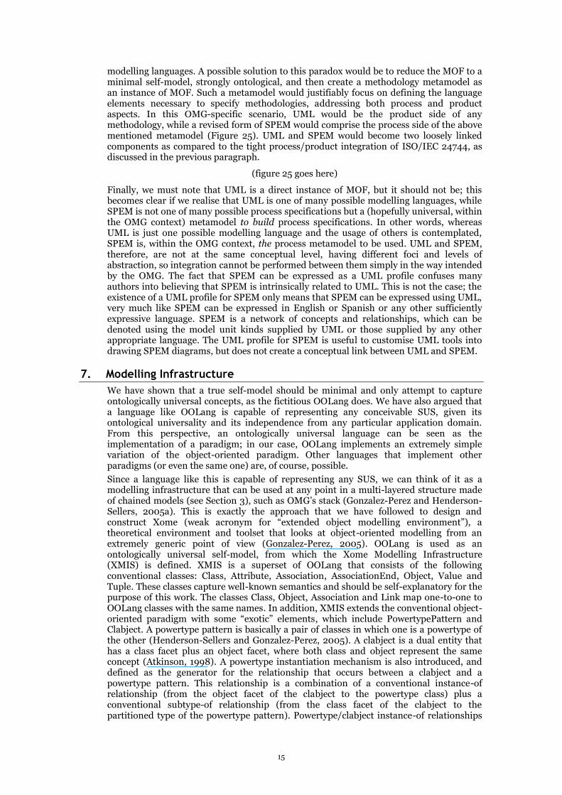
We can formalise our previous description (“models of a certain kind will make use of a common set of model unit kinds”, see above) by saying that each model kind uses a given set of model unit kinds. For example, architectonic scale models use Wall, Room and Door while UML class models use Class, Association and Attribute. Since model unit kinds tend to appear in semantically cohesive clusters, we can name these clusters “modelling languages” or simply “languages”, and define a (modelling) language as an organised collection of model unit kinds that focus on a particular modelling perspective. This is not too different from the idea of idealised cognitive models (Lakoff, 1990), chapter 4. For example, we can define an Architectonic Modelling Language as the organised collection of Wall, Room, Door, etc., or the UML Class Modelling Language as the organised collection of Class, Attribute, Association, etc. Since any model always belongs to a given model kind, and every model kind is related to a particular modelling language, the set of model unit kinds that a model uses is easy to determine (Figure 13).
(figure 13 goes here)
We must make three points here. First of all, a modelling language is an organised collection of model unit kinds. By “organised”, we mean that the model unit kinds that form part of a language must be carefully related to each other so that their semantics are valid. For example, UML defines how Class and Attribute are related to each other, and that definition governs how UML class models can make use of model units of these kinds. Model unit kinds, in this sense, are not defined independently but usually as a
9
metamodel, i.e. a model of potential models6. From this perspective, the specification of UML’s abstract syntax (OMG, 2004; OMG, 2005b) is a metamodel. Secondly, a language does not need to be composed of words or other conventionally-looking units; our architectonic example describes a language composed of concepts such as Wall, Room, Door, etc. This is well illustrated by the pattern language of Alexander described in (Alexander et al., 1977). Finally, concrete syntax (also known as “notation”, i.e. the visual or otherwise perceivable artefacts that depict elements in the language) is not part of a modelling language. UML, and OMG’s suite of technologies in general, use a different definition of “language”, one that often allows for the inclusion of concrete syntax as a component of the language. This, however, is different to the line of discourse that we are following here. Indeed, many works equate “notation” with “modelling language” (for example, (Fowler and Kendall, 2000), p. 1: “The modelling language is the […] notation that…”) or do not differentiate between the abstract syntax of the language (i.e. the model unit kinds) and its concrete syntax or true “notation” (for example, (Eriksson and Penker, 1998), p. 7). However, we need to acknowledge two facts. Firstly, a language can be fully specified by formalising its abstract syntax and semantics; notation is not necessary for this purpose — see (Greenfield and Short, 2004), chapter 6. In fact, there are good examples of modelling languages, such as ISO/IEC 24744 (ISO/IEC, 2007), that exist without a notation. Secondly, multiple notations can be obtained that are capable of depicting the model unit kinds of a given language. For example, a UML class model can be shown as boxes and lines on a sheet of paper (one notation, eminently graphical), or as a sequence of XML tags in a file (another notation, textual). For these reasons, we prefer to consider the concept of notation as separate from the concept of language, although closely related (Figure 14). An analogy here is that the same concepts may be expressed (or “notated”) using different languages and even alphabets (e.g. Roman, Cyrillic).
(figure 14 goes here)
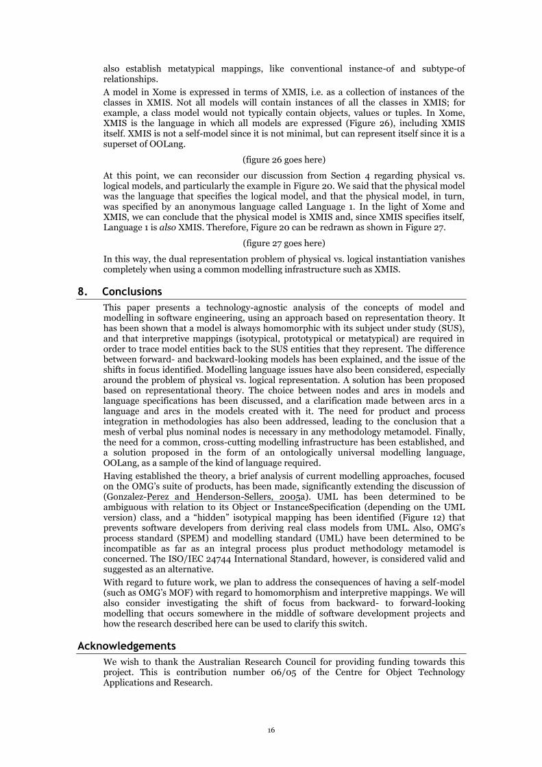
Since every model belongs to a given model kind, which in turn uses a particular language, we can state that every model uses a particular language (Figure 15).
(figure 15 goes here)
Furthermore, we must realise that a model is built by creating and assembling model units of the appropriate model unit kinds. The available model unit kinds, of course, are defined by the language associated with the corresponding model kind (see Figure 14). Each model unit in the model, therefore, is “of” a given model unit kind. This relationship, although shown in Figure 14 as an association, has strong instance-of semantics. For example, it is easy to understand that each class in a class model is an instance of a Class model unit kind, and each attribute in the same model is an instance of an Attribute model unit kind. Similarly, each door in an architectural scale model is an instance of a Door model unit kind. Since the relationship between model units and their associated model unit kinds is that of instance-of, we can say that a metatypical interpretive mapping between them can be established and, for that matter, model unit kinds in a language actually represent the associated model units in the model. As a consequence, we can state that a language not only serves to express models, but it also represents (metatypically) any possible model of the associated model kinds (Figure 16).
(figure 16 goes here)
Different models in a model chain may use different languages. For example, it is possible to construct a UML class model of a program that, in turn, is expressed in C#. The UML class model uses UML as its language, while the computer program uses C# as its (modelling) language. In this context, the C# program is the SUS of the UML class model, and also a model of the final system. We have established in Section 2 that a model and its SUS must be homomorphic, so we should expect, in our example, that the UML model and its SUS, namely the C# program, are homomorphic too. This means that each individual structural element of the UML model must be unequivocally mapped to one or more structural elements of the C# program. Since both the UML model and the C# program are models, we can argue that the structural elements to consider in any homomorphism are, precisely, the model unit kinds that compose such models.
6 A metamodel is often incorrectly defined as “a model of a model” rather than (correctly) as “a model of models” (Favre, 2005).

10
Consequently, the homomorphism between the UML class model and the C# program is given by a set of interpretive mappings from the model units of the UML class model and the model units of the C# program. For example, an association in the UML model could be mapped to a referenced object in the C# program. Since model units can be classified into model unit kinds, we can abstractly define the interpretive mappings between these models by looking at the model unit kinds that compose their respective languages and by establishing the appropriate language-level mappings between them. For example, we could state that the Association model unit kind of the UML modelling language can be mapped to a ReferencedObject model unit kind of the C# language. We need to emphasise that these language-level mappings are not interpretive mappings; they operate between model unit kinds rather than between model units. Specifically, the cardinalities of such mappings can be many-to-one or many-to-many (i.e. multiple model unit kinds in the model can be mapped to the same model unit kind in the SUS). This does not mean that the language-level mappings are useless; quite the contrary, they form the infrastructure on which code can be generated from models or, more generically, models can be transformed into other models, perhaps automatically as proposed by MDA (OMG, 2003a).
A particularly interesting case of language-level mappings is that of “seamless transition”. This term has been used in the literature —for example, (Henderson-Sellers, 1992), p. 10-12; (Meyer, 1997), p. 22-23— to claim that object-orientation provides a seamless transition between development phases, i.e. the same concepts (namely, object and class) are used along the development process from the beginning to the end of a project. If this claim is true, we should be able to define Object and Class model unit kinds and make them components of every single language that is used along an object-oriented software development project. Again using our previous example, we can see, in fact, that both UML and C# incorporate the concepts of Class and Object. Having reached this point, we must ask, is the UML Class the same thing as the C# Class (ditto for Object)? In other words, do UML Class and C# Class have the same semantics? If they do, the language-level mapping between them is straightforward, and the promised seamlessness is achieved. However, it is easily shown that this is not the case. Although a UML class and a C# class correspond roughly to the same idea, they differ significantly in the details. As we have explained in this Section, model unit kinds are not defined in isolation but in close relationship to each other within a given language. Therefore, we should expect that the semantics of any model unit kind are strongly conditioned by the neighbouring model unit kinds within that specific modelling language. For example, C# Class is related to C# Property, which does not have a matching concept in UML; therefore, C# Class is somewhat different to UML Class. The necessarily cumulative effect of little differences like this makes the language-level mappings between UML Class and C# Class non-trivial although not too complex either, since, as we have said, they correspond to the same overall idea. We must conclude, therefore, that seamlessness in object-oriented modelling exists only at certain level of abstraction rather than being an absolute truth. In this sense, seamlessness is a useful concept to illustrate the fact that most languages in an object-oriented environment do incorporate a core of closely related concepts, but it should not be used as a formal statement at a more detailed level.
Another interesting issue related to modelling languages is that of “logical” vs. “physical” representation (the terms “logical” and “physical”, in this context, are taken from (Atkinson and Kühne, 2002), although these contrasting names are much, much older). Consider a book object in a library management system; is this object an instance of the Book class, or is it an instance of the Object class? In other words: is the book object a book or an object? It is correct to say that the book object is-a7 book, but it is also correct to say that it is-an object (Figure 17).
(figure 17 goes here)
From a representational perspective, the book object is represented by two different model entities: the Book class and Object class. From a UML perspective, the book object seems to be an instance of two unrelated classes, which is illegal. To answer this apparent contradiction, we must realise that Book and Object do not belong to the same model. Two different models are involved here: a physical model containing the Object class, plus
7 In different contexts, is-a can refer to either is-an-instance-of or is-a-kind-of (Atkinson et al., 2000). Clearly here it means the former.

11
a logical model containing the Book class – as hinted at in (Atkinson and Kühne, 2003). Both models represent the SUS in which the book object exists (Figure 18).
(figure 18 goes here)
We have defined a model kind as a specific kind of model, characterised by its focus, purpose and level of abstraction. The two models involved in Figure 18 have different purposes and different levels of abstraction, so we can say that they are of different kinds. Physical models represent SUS ontologically, i.e. using model unit kinds that correspond to the most generic and universal ideas that we can think of, such as Object or Class, sometimes called Entity and Category, arguably inherent to the human mind according to (Barkow et al., 1992) and (Lakoff, 1990). On the other hand, logical models represent SUS epistemologically, i.e. using context-dependent and domain-specific model unit kinds. The general idea of object (or entity) is widely applicable and perhaps universal, while the idea of a book is dependent on a specific socio-cultural environment and application domain. Notice that our use of the word “ontologically” is not related to the common use of “ontology” in computer science, which we (and most dictionaries) deem inappropriate8, but rather to the definition of ontology as given by e.g. (Bunge, 1977; Bunge, 1979).
Some observations can be made with regard to Language 1 and Language 2 in Figure 18. Applying conventional object-oriented wisdom, we can see that the class Book in the logical model can be expressed as a subtype of the class Object in the physical model. In fact, most object-oriented programming languages and class libraries contain a class (often called “Object” or something similar) that acts as the default supertype of any other class possibly defined. What would be the implications of defining Book as a subtype of Object? The most evident consequence would be that the subtype-of relationship from Book to Object defines a metatypical interpretive mapping, which, in turn, suggests that the physical model represents the logical model, which becomes a SUS of the former. This makes sense, since the physical model has been described as ontologically universal and, therefore, we can assume that it is capable of representing any possible SUS. Given this, the logical model can, consequently, be represented by both the physical model and Language 2 (Figure 19).
(figure 19 goes here)
Given that the physical model has been determined to represent the logical model, the fact that it also represents the SUS (the Book Management System in our example) is given by the transitiveness of the representation process. We must consider, at this point, whether the physical model is not simply the same thing as Language 2. By reorganising the diagram in Figure 19 it is shown that, in fact, Physical Model is just another name for Language 2 (Figure 20).
(figure 20 goes here)
The problem of dual representation (i.e. physical vs. logical), explicitly exposed in the context of software development methodologies by several works, such as (Atkinson and Kühne, 2002; Henderson-Sellers and Gonzalez-Perez, 2005), is thus solved when we consider it in the light of representation theory since the physical model is not a model of the SUS but is the language used to express the model of the SUS.
There is a final issue regarding modelling languages that is worth considering. How are modelling languages defined? Usually, a modelling language is formally or semi-formally specified as a forward-looking model that represents any possible SUS that can be created with the language. For example, UML is defined by the so-called UML metamodel, which is simply a specification (a forward-looking model) of any potential valid UML user model (see Figure 11). It should be noted that the UML metamodel is not a specification of UML,
8 Ontology refers to the being of the world as it exists, and independently of any perception or cognition that may be performed on it; epistemology, more correctly, refers to how humans perceive and conceptualise the observed world. In other words, the ontology of the world would not change had human beings never existed, whereas epistemology is tightly tied to human existence, perception and cognition. It can be argued that other intelligent species would enjoy different epistemologies, but their existence (or inexistence) does not alter the ontology of the world. In computer science today, the word “ontology” is commonly used to mean a conceptual (and therefore human-mediated) model, a meaning that is more closely related to epistemology than to true ontology.
12
but is the UML language itself, like the phonetics, syntax, grammar, semantics and pragmatics of English is not a specification of English but English itself. If we want a specification of UML, we need to look for a forward-looking model that represents UML; MOF is the supposed answer. MOF can be seen as either the language in which UML is expressed, or a model of UML. In fact, it is both, since languages represent the models that they express, as we have shown above. In turn, UML is both a model of UML user models and the language in which they are expressed (Figure 21), a language that will evolve by focussing on “the most pragmatic concepts will survive and thrive, and those that are impractical will be garbage collected” (Kobryn, 2004).
(figure 21 goes here)
Both MOF and UML contain a Class model unit kind. As we have established earlier, these two Class model unit kinds are different, although roughly associated with the same ontological idea of a class. Some authors have pointed out that the fact that MOF contains a Class model unit kind makes it an invalid metamodel of UML, since Class belongs to UML. We must emphasise here that the two Class model unit kinds are completely different entities and therefore this argument is not valid. We agree that, in both cases, Class corresponds to the well-known concept of a class in the object-oriented paradigm; however, their formal semantics are different and, consequently, they comprise slightly different formal variations of such a common, non-formalised object-oriented paradigm.
5. Nodes and Arcs
We have described, in the previous section, how physical models take an ontological view of the SUS that they represent — see also (Guizzardi et al., 2002). We can argue that the very basic core model unit kinds at this level are Object, Class, Association and Link. In general, Object is useful to represent SUS entities isotypically or prototypically, while Class is useful to represent them metatypically. We can also say that Link is useful to represent connections between SUS entities isotypically or prototypically, while Association can be used to represent connections between SUS entities metatypically. Put differently, the very basic ontological ideas that we need to model are those of “things” (captured by the Object and Class model unit kinds) and “connections between things” (captured by Link and Association) (Lakoff, 1990). These four model unit kinds can be grouped into a universal object-oriented language tentatively called OOLang.9
Since OOLang is ontologically universal, we can argue that anything can be represented by a model that uses OOLang. This means that any SUS can be represented as a collection of “things” and “connections between things”. In other words, as a graph of nodes and arcs. Ontologically speaking, we can say that relevant entities in the SUS are represented as nodes (either objects or classes), and relevant semantic connections between entities in the SUS are represented as arcs (either links or associations). But, what is a “relevant entity”? Since any model has a purpose, we need to assess relevance on a case by case basis. For example, when constructing a library management system, the relevant entities that are detected may include books, clients and loans. In addition, relevant connections can be identified, namely between books and loans and between loans and clients. The three identified relevant entities can be represented in a model (let’s assume we use the UML language) by three classes, namely Book, Client and Loan, and the connections between them by the appropriate associations. An alternative way of modelling the same SUS would be to consider only two classes, Book and Client, and model Loan as an association between them (Figure 22).
(figure 22 goes here)
Although software modelling best practices would perhaps advocate modelling loans as a class, the mere fact that some people consider the option of representing loans as an arc (rather than a node), while nobody would consider modelling books or clients as arcs, is significant. This difference underscores that the decision of modelling a relevant entity as a node or as an arc is not entirely objective or completely pre-determined by the nature of
9 OOLang is not a proposal for a new language. Neither have we tried to assess whether ER could be used instead. The label OOLang is given merely as a convenience for the group of ideas we are exploring in the context of this paper and the theory development i.e. OOLang is fictitious and temporary.

13
the SUS entity. The focus, purpose and level of abstraction of the model being constructed can, in fact, influence this decision.
This issue gets particularly complicated when specifying modelling languages. As we have seen in the previous section, a modelling language (let’s call it the target) is specified by using another modelling language, which represents the target. For example, Figure 21 shows how MOF specifies UML. Some classes in UML, such as Class and Attribute, represent SUS entities that are unequivocally seen as nodes. Other UML classes, however, represent SUS entities that are often referred to as “connections between things”, such as Association and Generalization. The concept of an association, for example, clearly refers to the connection between two things, but UML has chosen to represent it as a class (in the metamodel) rather than an association between classes because it is of key relevance. Furthermore, Association in UML must be a “thing” rather than a “connection between things” because it must be connected to other things itself. MOF, the language in which UML is specified, allows for a higher amount of detail in classes than in associations, so it makes sense that key SUS entities are modelled by UML as classes rather than associations. Other “connections between things”, such as the relationship between a class and each of its attributes, are not judged as being so important as to deserve a class in UML, so they are represented by an association between the involved classes. We must realise, at this point, that models are often represented by graphical depictions, and such depictions are models themselves that represent the said models. For example, the UML diagram shown in Figure 22 is a representation of a UML model that resides in my mind. Note the emphasis on the words “diagram” and “model”. The UML model in my mind, in turn, is the SUS of the UML diagram and, at the same time, represents some other SUS. Diagrams also use the concepts of nodes and arcs. For example, in the bottom half of Figure 22, two nodes (the Book and Client class boxes) are shown, as well as an arc between them (the HasLoanOn association line). However, it would be wrong to think that an arc in the diagram (or in the model, since the diagram and its SUS are isotypical) is always a representation of a “connection between things” in the SUS. For example, all three model entities (the two classes plus the association) are represented in the UML specification by nodes, namely the classes Class and Association. Arcs in the UML specification (such as the association between Class and Association) are not explicitly represented in the diagram, but topology or location is used. For example, the association line corresponding to the HasLoanOn association touches the class boxes corresponding to Book and Client; this is implicit notation for the association, in the UML specification, between Class and Association. Although this is a matter of pure convention, UML tends to use explicit graphical artefacts for nodes in its specification, while implicit notation is often used for arcs.
Finally, we must stress that the choice of arc vs. node when representing an SUS entity pertains ultimately to the language designer; it is not entirely given by the SUS being represented. By making decisions in this respect, the language designer injects a given bias into the language that makes it more (or less) appropriate for different purposes and levels of abstraction.
6. Integrating Product and Process
The term “metamodel” has been used so far in this paper to mean “a model of models” (Favre, 2005). This is one of the two meanings often found in the literature, especially in the context of information modelling. The second meaning is usually found in the process modelling and method engineering literature, and roughly corresponds to “a model of methodologies”. An example of the first meaning is the UML metamodel (OMG, 2004); an example of the second, the OPEN metamodel (Firesmith and Henderson-Sellers, 2002). In the context of software development methodologies, metamodels are simply forward-looking models that represent any possible methodology that can be created. Like their model-oriented cousins (see first meaning of “metamodel”, above), methodology metamodels can be seen also as languages that can be used to express, in this case, methodologies. In any case, the content of a methodology metamodel depends on what the metamodel authors understand by “methodology”. We will adopt the definition that we proposed and justified (Gonzalez-Perez and Henderson-Sellers, 2006): a methodology is a specification of the process to follow and the work products to be generated, plus consideration of the people and tools involved, during a software development effort. Since a methodology needs to consider both process and product
14
aspects, and a methodology metamodel must be able to represent any possible relevant methodology, then process and product aspects must be integrated within the metamodel (Atkinson and Kühne, 2001b; Rolland, 2005). The only publicly available standard metamodel, as far as we know, that achieves this, is ISO/IEC 24744 “Software Engineering Metamodel for Development Methodologies” (ISO/IEC, 2007) (Figure 23) built on top of the Australian Standard AS 4651-2004 “Standard Metamodel for Software Development Methodologies” (SA, 2004). The philosophy underpinning such integration is a linguistic simile: meaningful messages are built by applying actions to objects or, more specifically, complete sentences are constructed by combining verbs and nouns. Verbs specify the actions that are performed, while nouns denote the authors and receivers of the said actions. Verbs without nouns can only specify actions, but an action needs a noun on which to be performed; similarly, nouns without verbs can only specify receivers or authors of actions, but not the actions themselves. Translating this into the methodology field, a software development process defines the actions to be performed when developing software, but these actions are meaningless without a detailed definition of the producers that execute the actions and the products that are involved. Similarly, products of software development (such as models or documents) alone are not enough; an indication of the process appropriate to create and employ them is necessary.
(figure 23 goes here)
ISO/IEC 24744 is intended to be used by methodologists in creating specific, tailored methodologies (see Method Domain in Figure 24). On the process side, ISO/IEC 24744 offers classes that allow the methodologist to define kinds of activities, tasks, techniques and phases, among others (Metamodel Domain in Figure 24). This falls within the same scope as OMG’s SPEM (OMG, 2005a). From the product side, ISO/IEC 24744 offers classes that allow the methodologist to define model kinds, languages and model unit kinds. This falls within the same scope as OMG’s MOF (OMG, 2002). ISO/IEC 24744 defines associations between process-related classes and product-related classes. Consequently, the appropriate links can be defined between process and product elements in the methodology. For example, a methodologist could define a task kind named “Write class code”, which specifies what to do in order to write the source code for any given class. This task specification, however, is meaningless unless there is a clear understanding of what a class is. SPEM, for example, would allow the methodologist to define this task too, but since it does not integrate product modelling aspects, no meaningful link could be established between this task and the concept of a class. In other words, the designer might (inadvertently) use a definition for Class that is incompatible, ambiguous or unintelligible to other users. With ISO/IEC 24744, on the other hand, the methodologist could define a model unit kind named “Class” and attach the appropriate definition, and then link the “Write class code” task kind to the “Class” model unit kind to reflect the fact that the said task refers to the said model unit kind. The capability of ISO/IEC 24744 to allow the methodologist to define both process and product aspects does not imply that both must be defined every time a methodology is needed; a method engineering approach (Brinkkemper, 1996) guarantees that a significant repository of pre-defined methodology components is maintained and re-used as necessary.
(figure 24 goes here)
In contrast, the OMG suite of products would need to be integrated at the most abstract level possible in order to achieve a similar degree of power. MOF would seem to be an appropriate candidate for such as integration but, unfortunately, MOF mixes together two different concerns: on the one hand, MOF tries to define the infrastructure necessary to define modelling languages (such as UML); on the other hand, it tries to be a self-model so it can fulfil its role at the top of the hierarchy. Our claim here is that a true self-model should be minimal and as close as possible to the ontologically universal OOLang language introduced in Section 5 or to the metametamodel of CDIF (ISO/IEC, 1998). If the self-model is not minimal (i.e. contains entities that are not used by the self-model itself), then these entities would not have any interpretive mappings to any SUS entities, which violates one of the premises in our theory (see Section 2). From this perspective, and for MOF to be a self-model, every class in it should have instances that are part of MOF itself. Since MOF is a language specification, structural by nature, classes such as Operation and Exception cannot have instances that are part of MOF. Therefore, we must conclude that it contains more classes than it needs to define itself. Of course, this may well be a consequence of trying to offer the necessary infrastructure to represent
15
modelling languages. A possible solution to this paradox would be to reduce the MOF to a minimal self-model, strongly ontological, and then create a methodology metamodel as an instance of MOF. Such a metamodel would justifiably focus on defining the language elements necessary to specify methodologies, addressing both process and product aspects. In this OMG-specific scenario, UML would be the product side of any methodology, while a revised form of SPEM would comprise the process side of the above mentioned metamodel (Figure 25). UML and SPEM would become two loosely linked components as compared to the tight process/product integration of ISO/IEC 24744, as discussed in the previous paragraph.
(figure 25 goes here)
Finally, we must note that UML is a direct instance of MOF, but it should not be; this becomes clear if we realise that UML is one of many possible modelling languages, while SPEM is not one of many possible process specifications but a (hopefully universal, within the OMG context) metamodel to build process specifications. In other words, whereas UML is just one possible modelling language and the usage of others is contemplated, SPEM is, within the OMG context, the process metamodel to be used. UML and SPEM, therefore, are not at the same conceptual level, having different foci and levels of abstraction, so integration cannot be performed between them simply in the way intended by the OMG. The fact that SPEM can be expressed as a UML profile confuses many authors into believing that SPEM is intrinsically related to UML. This is not the case; the existence of a UML profile for SPEM only means that SPEM can be expressed using UML, very much like SPEM can be expressed in English or Spanish or any other sufficiently expressive language. SPEM is a network of concepts and relationships, which can be denoted using the model unit kinds supplied by UML or those supplied by any other appropriate language. The UML profile for SPEM is useful to customise UML tools into drawing SPEM diagrams, but does not create a conceptual link between UML and SPEM.
7. Modelling Infrastructure
We have shown that a true self-model should be minimal and only attempt to capture ontologically universal concepts, as the fictitious OOLang does. We have also argued that a language like OOLang is capable of representing any conceivable SUS, given its ontological universality and its independence from any particular application domain. From this perspective, an ontologically universal language can be seen as the implementation of a paradigm; in our case, OOLang implements an extremely simple variation of the object-oriented paradigm. Other languages that implement other paradigms (or even the same one) are, of course, possible.
Since a language like this is capable of representing any SUS, we can think of it as a modelling infrastructure that can be used at any point in a multi-layered structure made of chained models (see Section 3), such as OMG’s stack (Gonzalez-Perez and Henderson-Sellers, 2005a). This is exactly the approach that we have followed to design and construct Xome (weak acronym for “extended object modelling environment”), a theoretical environment and toolset that looks at object-oriented modelling from an extremely generic point of view (Gonzalez-Perez, 2005). OOLang is used as an ontologically universal self-model, from which the Xome Modelling Infrastructure (XMIS) is defined. XMIS is a superset of OOLang that consists of the following conventional classes: Class, Attribute, Association, AssociationEnd, Object, Value and Tuple. These classes capture well-known semantics and should be self-explanatory for the purpose of this work. The classes Class, Object, Association and Link map one-to-one to OOLang classes with the same names. In addition, XMIS extends the conventional object-oriented paradigm with some “exotic” elements, which include PowertypePattern and Clabject. A powertype pattern is basically a pair of classes in which one is a powertype of the other (Henderson-Sellers and Gonzalez-Perez, 2005). A clabject is a dual entity that has a class facet plus an object facet, where both class and object represent the same concept (Atkinson, 1998). A powertype instantiation mechanism is also introduced, and defined as the generator for the relationship that occurs between a clabject and a powertype pattern. This relationship is a combination of a conventional instance-of relationship (from the object facet of the clabject to the powertype class) plus a conventional subtype-of relationship (from the class facet of the clabject to the partitioned type of the powertype pattern). Powertype/clabject instance-of relationships
16
also establish metatypical mappings, like conventional instance-of and subtype-of relationships.
A model in Xome is expressed in terms of XMIS, i.e. as a collection of instances of the classes in XMIS. Not all models will contain instances of all the classes in XMIS; for example, a class model would not typically contain objects, values or tuples. In Xome, XMIS is the language in which all models are expressed (Figure 26), including XMIS itself. XMIS is not a self-model since it is not minimal, but can represent itself since it is a superset of OOLang.
(figure 26 goes here)
At this point, we can reconsider our discussion from Section 4 regarding physical vs. logical models, and particularly the example in Figure 20. We said that the physical model was the language that specifies the logical model, and that the physical model, in turn, was specified by an anonymous language called Language 1. In the light of Xome and XMIS, we can conclude that the physical model is XMIS and, since XMIS specifies itself, Language 1 is also XMIS. Therefore, Figure 20 can be redrawn as shown in Figure 27.
(figure 27 goes here)
In this way, the dual representation problem of physical vs. logical instantiation vanishes completely when using a common modelling infrastructure such as XMIS.
8. Conclusions
This paper presents a technology-agnostic analysis of the concepts of model and modelling in software engineering, using an approach based on representation theory. It has been shown that a model is always homomorphic with its subject under study (SUS), and that interpretive mappings (isotypical, prototypical or metatypical) are required in order to trace model entities back to the SUS entities that they represent. The difference between forward- and backward-looking models has been explained, and the issue of the shifts in focus identified. Modelling language issues have also been considered, especially around the problem of physical vs. logical representation. A solution has been proposed based on representational theory. The choice between nodes and arcs in models and language specifications has been discussed, and a clarification made between arcs in a language and arcs in the models created with it. The need for product and process integration in methodologies has also been addressed, leading to the conclusion that a mesh of verbal plus nominal nodes is necessary in any methodology metamodel. Finally, the need for a common, cross-cutting modelling infrastructure has been established, and a solution proposed in the form of an ontologically universal modelling language, OOLang, as a sample of the kind of language required.
Having established the theory, a brief analysis of current modelling approaches, focused on the OMG’s suite of products, has been made, significantly extending the discussion of (Gonzalez-Perez and Henderson-Sellers, 2005a). UML has been determined to be ambiguous with relation to its Object or InstanceSpecification (depending on the UML version) class, and a “hidden” isotypical mapping has been identified (Figure 12) that prevents software developers from deriving real class models from UML. Also, OMG’s process standard (SPEM) and modelling standard (UML) have been determined to be incompatible as far as an integral process plus product methodology metamodel is concerned. The ISO/IEC 24744 International Standard, however, is considered valid and suggested as an alternative.
With regard to future work, we plan to address the consequences of having a self-model (such as OMG’s MOF) with regard to homomorphism and interpretive mappings. We will also consider investigating the shift of focus from backward- to forward-looking modelling that occurs somewhere in the middle of software development projects and how the research described here can be used to clarify this switch.
Acknowledgements
We wish to thank the Australian Research Council for providing funding towards this project. This is contribution number 06/05 of the Centre for Object Technology Applications and Research.

17
References
Alexander, C., Ishikawa, S. and Silverstein, M. (1977) A Pattern Language, Oxford University Press, New York.
American National Standards Institute (1989). X3.138. Information Resource Dictionary System.
Atkinson, C. (1998). Supporting and Applying the UML Conceptual Framework. In «UML» 1998: Beyond the Notation. LNCS 1618. Springer-Verlag: Berlin (Germany). 21-36.
Atkinson, C. and Kühne, T. (2001a). The Essence of Multilevel Metamodelling. In «UML» 2001: Modeling Languages, Concepts and Tools. LNCS 2185. Springer-Verlag: Berlin (Germany). 19-33.
Atkinson, C. and Kühne, T. (2001b), Processes and Products in a Multi-level Metamodeling Architecture, Int. J. Software Eng. and Knowledge Eng., 11, 761-783.
Atkinson, C. and Kühne, T. (2002), Rearchitecting the UML Infrastructure, ACM Transactions on Modeling and Computer Simulation, 12, 290-321.
Atkinson, C. and Kühne, T. (2003), Model-Driven Development: a Metamodeling Foundation, IEEE Software, 20, 36-41.
Atkinson, C., Kühne, T. and Henderson-Sellers, B. (2000), To Meta or Not To Meta - That Is the Question, Journal of Object-Oriented Programming, 13, 32-25.
Barkow, J. H., Cosmides, L. and Tooby, J. (1992) The Adapted Mind: Evolutionary Psychology and the Generation of Culture, Oxford University Press, New York.
Bézivin, J. (2005), On the Unification Power of Models, Software and Systems Modelling, 4, 171-188.
Brinkkemper, S. (1996), Method Engineering: Engineering of Information Systems Development Methods and Tools, Information and Software Technology, 38, 275-280.
Bunge, M. (1977) Treatise on Basic Philosophy - Ontology I: The Furniture of the World, Reidel, Boston, MA.
Bunge, M. (1979) Treatise on Basic Philosophy - Ontology II: A World of Systems, Reidel, Boston, MA.
Davies, I., Green, P., Rosemann, M. and Gallo, S. (2004). Conceptual Modelling - What and Why in Current Practice. In 23rd International Conference on Conceptual Modelling (ER 2004). 8-12 November 2004. LNCS 3288. Springer-Verlag. 30-42.
Dolk, D. R. and Kirsch, R. A., II (1987), A Relational Information Resource Dictionary System, Communications of the ACM, 30, 48-61.
Eriksson, H.-E. and Penker, M. (1998) UML Toolkit, John Wiley & Sons, New York.
Favre, J.-M. (2005). Foundations of model (driven) (reverse) engineering: models; Episode I: Stories of The Fidus Papyrus and of The Solarus. In Seminar 04101 "Language Engineering for Model-Driven Software Development". Dagstuhl Seminar Proceedings Internationales Begegnungs
Firesmith, D. G. and Henderson-Sellers, B. (2002) The OPEN Process Framework, Addison-Wesley, London.
Fowler, M. and Kendall, S. (2000) UML Distilled, Addison-Wesley, Reading, MA.
Gonzalez-Perez, C. (2002) Sistemas de Información para Arqueología: Teoría, Metodología y Tecnologías, Archaeopress, Oxford (UK).
Gonzalez-Perez, C. (2005). Tools for an Extended Object Modelling Environment. In 10th IEEE International Conference on Engineering of Complex Computer Systems (ICECCS). 16-20 June 2005. IEEE Computer Society. 20-23.

18
Gonzalez-Perez, C. and Henderson-Sellers, B. (2005a). A Representation-Theoretical Analysis of the OMG Modelling Suite. In The 4th International Conference on Software Methodologies, Tools and Techniques. 28-30 September 2005. Frontiers in Artificial Intelligence and Applications 129. IOS Press: Amsterdam. 252-262.
Gonzalez-Perez, C. and Henderson-Sellers, B. (2005b), Templates and Resources in Software Development Methodologies, Journal of Object Technology, 4, 173-190.
Gonzalez-Perez, C. and Henderson-Sellers, B. (2006), A Powertype-Based Metamodelling Framework, Software and Systems Modelling, 5, 72-90.
Greenfield, J. and Short, K. (2004) Software Factories, John Wiley & Sons.
Guizzardi, G., Herre, H. and Wagner, G. (2002). On the General Ontological Foundations of Conceptual Modelling. In 21st International Conference on Conceptual Modeling (ER). 7-11 October 2002. LNCS 2503. Springer-Verlag. 65-78.
Harkema, H. (1995). Automatic Detection and Correction of Syntax Errors in Tutoring Systems for Language Instruction. In Sixth Computational Linguistics in the Netherlands Meeting. UIA Center for Dutch Language and Speech: Antwerp (Belgium)
Henderson-Sellers, B. (1992) A Book of Object-Oriented Knowledge, Prentice-Hall, New York.
Henderson-Sellers, B. and Gonzalez-Perez, C. (2005). The Rationale of Powertype-Based Metamodelling. In Second Asia-Pacific Conference on Conceptual Modelling. 30 January - 4 February 2005. Australian Computer Science Communications vol. 7, number 6. Australian Computer Society. 7-16.
International Organization for Standardization / International Electrotechnical Commission (1998). ISO/IEC 15474-1. CDIF Framework - Part 1: Overview.
International Organization for Standardization / International Electrotechnical Commission (2007). ISO/IEC 24744. Software Engineering - Metamodel for Development Methodologies.
Jackson, M. (2002), Some Basic Tenets of Description, Software and Systems Modelling, 1, 5-9.
Kobryn, C. (2004), UML 3.0 and the Future of Modeling, Software and Systems Modelling, 3, 4-8.
Kühne, T. (2005). What Is a Model? In Seminar 04101 "Language Engineering for Model-Driven Software Development". Dagstuhl Seminar Proceedings Internationales Begegnungs
Lakoff, G. (1990) Women, Fire, and Dangerous Things, University of Chicago Press.
Ludewig, J. (2003), Models in Software Engineering —an Introduction, Software and Systems Modelling, 2, 5-14.
Martin, J. and Odell, J. (1992) Object-Oriented Analysis and Design, Prentice-Hall, Englewood Cliffs, NJ.
Meyer, B. (1997) Object-Oriented Software Construction, Prentice-Hall, Upper Saddle River, NJ.
Object Management Group (2002). formal/2002-04-03. Meta Object Facility (MOF) Specification, version 1.4.
OMG (2003a). MDA Guide, Object Management Group.
Object Management Group (2003b). formal/03-03-01. Unified Modelling Language Specification, version 1.5.
Object Management Group (2004). ptc/04-10-14. Unified Modelling Language Specification: Infrastructure, version 2.

19
Object Management Group (2005a). formal/05-01-06. Software Process Engineering Metamodel Specification, version 1.1.
Object Management Group (2005b). formal/05-07-04. Unified Modelling Language Specification: Superstructure, version 2.
Peterson, D. (Ed.) (1996) Forms of Representation, Intellect, Exeter (UK).
Rolland, C. (2005). Modelling Multi-Facetted Purposes of Artefacts. In The 4th International Conference on Software Methodologies, Tools and Techniques. 28-30 September 2005. Frontiers in Artificial Intelligence and Applications 129. IOS Press: Amsterdam. 3-17.
Standards Australia (2004). Standard Metamodel for Software Development Methodologies.
Sabetzadeh, M. and Easterbrook, S. (2005). An Algebraic Framework for Merging Incomplete and Inconsistent Views. In 13th IEEE International Conference on Requirements Engineering. IEEE Computer Society: Paris (France)
Seidewitz, E. (2003), What Models Mean, IEEE Software, 20, 26-31.
Stachowiak, H. (1973) Allgemeine Modelltheorie, Springer-Verlag, Wien.

20
Figures
SUS Model
Figure 1. A model and the SUS that it represents. A rectangular box represents a model. A rounded rectangle box represents a SUS. The arrow can be read as “represents”.
SUS Model
Figure 2. A model must be homomorphic with its SUS so the operations that are possible on the SUS are also possible on the model.
OO Model
of Reality
OO Design
Code
Reality
Figure 3. A model as an entity external to reality. Based on figure 5.1, page 68, of (Martin and Odell, 1992). Reprinted by permission of Pearson Education, Inc., Upper Saddle River, New Jersey.
reality
SUS Model
reality
SUS Model
Figure 4. A model is part of the same reality as its SUS.

21
SUS Model
SUSModel
Figure 5. On the top, a backward-looking model, which represents a pre-existing SUS. On the bottom, a forward-looking model, which represents an SUS that does not exist yet. Time is assumed to flow from left to right, and, therefore, the direction of the “represents” arrow depends on the kind of model.
Application
Domain
Final
System
… ? ...
Model 2
Model n-1
Model 1
Model n
Figure 6. Backward- and forward-looking models in a software development project. At some point during the project, focus shifts from looking back to the application domain into looking forward to the final system being built. Note that all the models in this diagram are represented as slightly rounded rectangles, meaning that they are models but also used as SUSs by other models.
SUSModel
Figure 7. Interpretive mappings between model entities and SUS entities, depicted by dotted-line arrows. For the sake of clarity, not all the mappings are shown in this figure.
SUSModelpentagon
Figure 8. Examples of isotypical, prototypical and metatypical interpretive mappings. A circle is shown to have an isotypical mapping. The shaded square on the model is an example (prototype) for any square in the SUS. The declaration of “pentagon” in the model is metatypically mapped to all possible pentagons in the SUS.

22
SUS Model 1 Model 2
Figure 9. A model that is the SUS for another model. Model 1 is a model of SUS, and Model 2 is a model of Model 1. Recall that rounded rectangles represent SUSs and rectangles represent models. In addition, slightly rounded rectangles represent models that are also used as SUSs by other models.
Application
DataX3.138
Application Data
Schema
Figure 10. Model chaining applied to data structure definition in X3.138. The standard defined a forward-looking model useful to specify application data schemata which, in turn, would be forward-looking models of the application data.
MOF
UML
User Model
Running
System
Figure 11. The four-layer OMG approach to model chaining. The top layer, MOF, is a self-model, i.e. it represents itself. Languages other than UML may appear under MOF and beside UML.
Book
name
isAbstract
Class
name
isAbstract
ob1 : Class
book1 : Book
name
isAbstract
Class
book1 : Book
Book
*
Figure 12. On the left-hand side, Book is shown as a class that is also an instance of Class, which is impossible within the conventional object-oriented paradigm; the asterisk signals this diagram as illegal. On the right-hand side, Book is shown as a class that is specified by the object ob1 through a forward-looking isotypical interpretive mapping (depicted as a solid arrow).
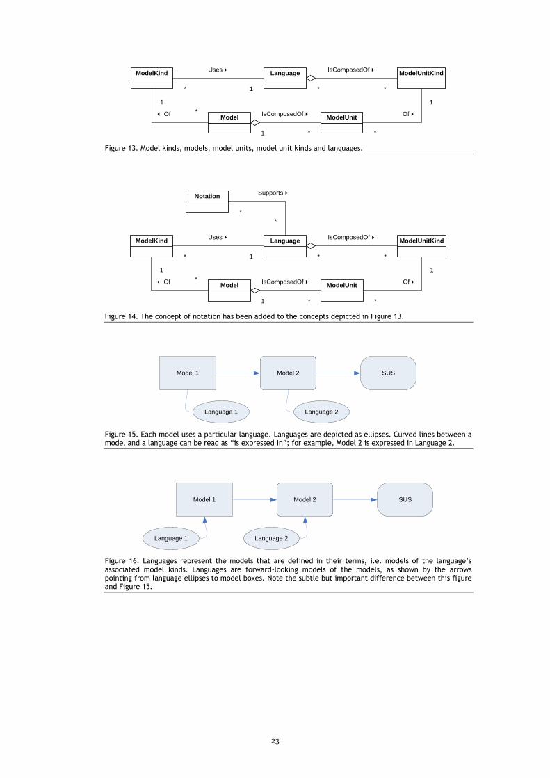
23
ModelKind
Model ModelUnit
ModelUnitKindLanguage
* *
IsComposedOf4
1 *
IsComposedOf4
* 1
Uses4
*
1
3 Of
*
1
Of4
Figure 13. Model kinds, models, model units, model unit kinds and languages.
ModelKind
Model ModelUnit
ModelUnitKindLanguage
* *
IsComposedOf4
1 *
IsComposedOf4
* 1
Uses4
*
1
3 Of
*
1
Of4
Notation
*
*
Supports4
Figure 14. The concept of notation has been added to the concepts depicted in Figure 13.
SUSModel 2Model 1
Language 1 Language 2
Figure 15. Each model uses a particular language. Languages are depicted as ellipses. Curved lines between a model and a language can be read as “is expressed in”; for example, Model 2 is expressed in Language 2.
SUSModel 2Model 1
Language 2Language 1
Figure 16. Languages represent the models that are defined in their terms, i.e. models of the language’s associated model kinds. Languages are forward-looking models of the models, as shown by the arrows pointing from language ellipses to model boxes. Note the subtle but important difference between this figure and Figure 15.
24
+Title
Book
Id = 197
Title = Alfanhuí
b
+Id
Object
«instanceOf»«instanceOf»
*
Figure 17. An object as instance of two classes. The object “b” is a book (it has a title) and also an object (it as an object id). This is not a valid UML diagram, as indicated by the asterisk, since an object must be a direct instance of only one class.
Book
Management
System
Physical
Model
Language 1
Language 2
Logical
Model
b
Object
Book
Figure 18. An SUS entity represented by two different model entities. The Book Management System is the SUS for two different models, Physical Model and Logical Model. The object “b” in this SUS is represented by one model entity in each of these two models.
Logical
Model
Book
Management
System
Physical
Model
Language 1
Language 2
b
Object
Book
Figure 19. Since Object is mapped to Book, Logical Model is represented by Physical Model as well as Language 2. Notice that Logical Model is now depicted with slightly rounded angles, trying to convey the idea that it is also a SUS (of Physical Model) as well as a model. This raises a question regarding the relationship between Physical Model and Language 2, since both represent the Logical Model.

25
Logical
Model
Book
Management
System
Language 1
Physical
Model
b
Object
Book
Figure 20. Physical Model is Language 2. The representation relationships and interpretive mappings given by transitiveness are not shown.
MOF
UML
Running
SystemUser Model
Book
Class
Class
b
Figure 21. MOF and UML as languages and models. Please compare with Figure 11.
+Title
Book Loan
+Name
Client
1 *
3 RefersTo
* 1
HeldBy4
+Title
Book
+Name
Client
* *
3 HasLoanOn
Figure 22. Two alternative ways (top and bottom) of modelling loans that clients have on books.
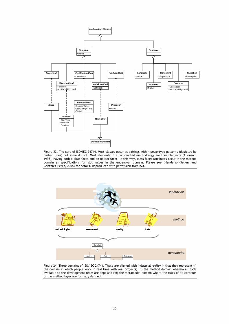
26
MethodologyElement
+Purpose
+MinCapabilityLevel
WorkUnitKind
+Description
WorkProductKind
+Definition
ModelUnitKind
+Name
Template Resource
+Name
Language
+Name
Notation
+Expression
Constraint
+Description
+MinCapabilityLevel
Outcome
EndeavourElement
+StartTime
+EndTime
+Duration
WorkUnit
+CreationTime
+LastChangeTime
+Status
WorkProduct
ModelUnit
+Description
GuidelineProducerKind
+Name
ProducerStage
StageKind
Figure 23. The core of ISO/IEC 24744. Most classes occur as pairings within powertype patterns (depicted by dashed lines) but some do not. Most elements in a constructed methodology are thus clabjects (Atkinson, 1998), having both a class facet and an object facet. In this way, class facet attributes occur in the method domain as specifications for slot values in the endeavour domain. Please see (Henderson-Sellers and Gonzalez-Perez, 2005) for details. Reproduced with permission from ISO.
endeavour
method
metamodelActivity
WorkUnit
Task Technique
* *
methodologies assessment quality tools
endeavourendeavour
methodmethod
metamodelmetamodelActivity
WorkUnit
Task Technique
* *
methodologies assessment quality toolsmethodologiesmethodologies assessmentassessment qualityquality toolstools
Figure 24. Three domains of ISO/IEC 24744. These are aligned with industrial reality in that they represent (i) the domain in which people work in real time with real projects; (ii) the method domain wherein all tools available to the development team are kept and (iii) the metamodel domain where the rules of all contents of the method layer are formally defined.

27
Methodology
MOF
User Model
Running
System
UML
Methodology Metamodel
Product
SideSPEM
Process Side
Figure 25. Reorganising OMG’s product suite into a meaningful hierarchy. The box labelled “MOF” on top represents a “distilled” MOF that is a true self-model. Notice how SPEM and UML reside at different conceptual levels.
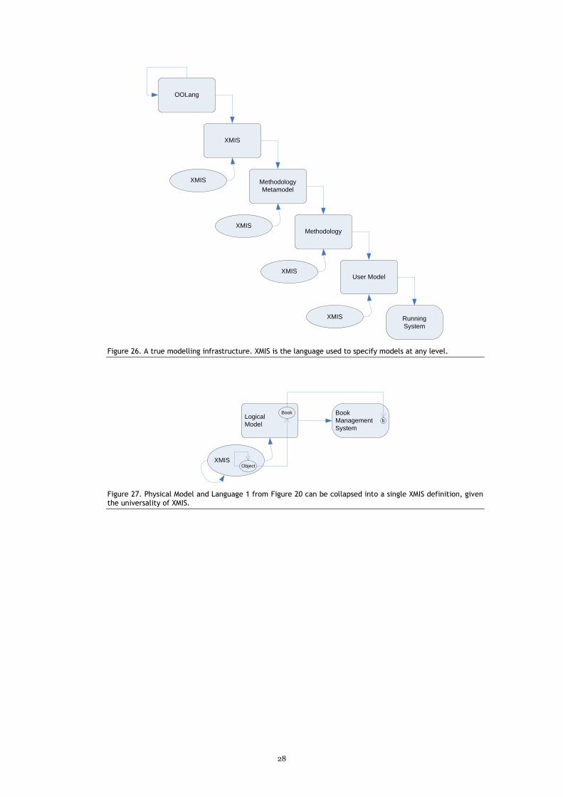
28
Methodology
Metamodel
Methodology
User Model
Running
System
XMIS
XMIS
XMIS
XMIS
XMIS
OOLang
Figure 26. A true modelling infrastructure. XMIS is the language used to specify models at any level.
Logical
Model
Book
Management
System
XMIS
b
Object
Book
Figure 27. Physical Model and Language 1 from Figure 20 can be collapsed into a single XMIS definition, given the universality of XMIS.

29
Bios
Cesar Gonzalez-Perez is a research project leader at the European Software Institute, where he leads research efforts in the areas of conceptual modelling, metamodelling and development methodologies. Previously, he worked over 3 years at the Faculty of IT of the University of Technology, Sydney. He is the founder and former technical director of Neco, a company based in Spain specialising in software development support services, which include the deployment and use of OPEN/Metis at small and mid-sized organisations. Cesar has also worked for the University of Santiago de Compostela in Spain as a researcher in computing & archaeology, and got his PhD in this topic in 2000. Cesar has published over 30 academic papers in software engineering and other areas.
Brian Henderson-Sellers is Director of the Centre for Object Technology Applications and Research and Professor of Information Systems at the University of Technology, Sydney (UTS). He is author or editor of 27 books and is well-known for his work in object-oriented and agent-oriented methodologies (MOSES, COMMA, OPEN, OOSPICE, FAME), object-oriented metrics and metamodelling. More recently, he has chaired workshops on these topics at OOPSLA and AOIS (Agent-Oriented Information Systems). He is Editor of the International Journal of Agent-Oriented Software Engineering and on the editorial board of Journal of Object Technology, Software and Systems Modeling and International Journal of Cognitive Informatics and Natural Intelligence. In July 2001, Professor Henderson-Sellers was awarded a Doctor of Science (DSc) from the University of London for his research contributions in object-oriented methodologies.
Related Documents