Modelling of thermally induced desiccation of geosynthetic clay liners in double composite liner systems Farzad M. Azad a , Abbas El-Zein a, * , R. Kerry Rowe b, ** , David W. Airey a a School of Civil Engineering, University of Sydney, Building J05, Sydney NSW 2006, Australia b GeoEngineering Centre at Queen’s-RMC, Queen’s University, Kingston, K7L 3N6 Canada article info Article history: Received 21 April 2011 Received in revised form 19 January 2012 Accepted 11 February 2012 Available online xxx Keywords: Geosynthetic clay liner Desiccation Double composite liner system Numerical model abstract Double composite liner systems (DCLSs) for municipal or hazardous waste landfills often include geo- membranes (GMBs) and geosynthetic clay liners (GCLs). Heat generated within such landfills due to exothermic degradation of organic matter or hydration of incinerator ash creates thermal gradients across the liner. These thermal gradients have the potential to induce a movement of moisture and create a risk of desiccation of the mineral component of the GCLs. This paper presents the results of a simulation of moisture redistribution and discusses the potential for desiccation of GCLs in DCLSs when subjected to thermal gradients using a numerical model developed by Zhou and Rowe (2003). The results from a series of laboratory experiments previously reported by the authors (Azad et al., 2011) are compared with model predictions. Two alternative soil water characteristic curves (SWCC), proposed by van Genuchten (1980) and Fredlund and Xing (1994), are implemented and their effects on the model’s accuracy assessed. The original model is found to predict reasonably well water distribution and the likelihood of thermal desiccation of the GCL. Ó 2012 Published by Elsevier Ltd. 1. Introduction Modern landfill barrier systems include a composite liner comprised of a geomembrane (GMB) and a geosynthetic clay liner (GCL) intended to reduce the outward transport of contaminants to a negligible level (Rowe et al., 2004). Although GMBs represent the primary barrier to leachate flow, leakage through perforated wrinkles and other defects in the GMB can occur and a GCL serves to minimize that leakage (El-Zein and Rowe, 2008; Rowe, 1998, 2005, 2012). In many parts of the world, 50e70% of the dry unit weight of the waste in municipal solid waste is organic matter (USEPA, 2003). The decomposition of organic matter is an exothermic process. The temperature increases due to this decay process have potential undesirable impacts on the long term performance of landfills due to temperature related changes in soil properties, a decrease in the service life of the GMB, and an increase in the risk of desiccation of clay liners (Abu-Hejleh and Znidarcic, 1995; Rowe et al., 1997, 2010; Rowe and Hoor, 2009; Southen and Rowe, 2005a, 2011). Field monitoring of temperature at or near the liner systems has shown that heat generated by waste material can reach 45 C in the underlying landfill liners (Koerner and Koerner, 2006; Rowe and Islam, 2009; Yesiller et al., 2005; Yoshida and Rowe, 2003), with temperatures of up to 60 C, and in unusual cases even higher, being reported (Collins, 1993; Koerner et al., 2008; Lefebvre et al., 2000; Rowe, 2005). Since the temperatures within the aquifer are typically 5e25 C (depending on location), this scenario leads to high temperature gradients. Due to the dependence of vapour density on temperature, this temperature gradient induces down- ward vapour migration from areas of higher temperature to areas of lower temperature. The resulting decrease in water content in the warmer areas causes liquid water to move upward because of the capillary pressure gradient (matric suction). Air also moves from areas of higher air pressure to those of lower air pressure. The combined effect of liquid water, vapour water, and air flow causes moisture movement and consequently, creates the potential for desiccation of the mineral component of GCL. Traditionally, two models have been used to simulate soil moisture movement in clay liners under non-isothermal conditions (Milly, 1982; Philip and de Vries, 1957). Milly’s model in particular can be applied to both saturated and unsaturated media because it uses capillary pressure, rather than moisture content, and temperature as the primary variables. Döll (1997) developed a numerical model based on two partial differential equations for * Corresponding author. Tel.: þ61 2 9351 7351; fax: þ61 2 9351 3343. ** Corresponding author. Tel.: þ61 3 533 6933; fax: þ61 3 533 6934. E-mail addresses: [email protected] (F.M. Azad), abbas.elzein@ sydney.edu.au (A. El-Zein), [email protected] (R.K. Rowe), david.airey@ sydney.edu.au (D.W. Airey). Contents lists available at SciVerse ScienceDirect Geotextiles and Geomembranes journal homepage: www.elsevier.com/locate/geotexmem 0266-1144/$ e see front matter Ó 2012 Published by Elsevier Ltd. doi:10.1016/j.geotexmem.2012.02.012 Geotextiles and Geomembranes 34 (2012) 28e38

Welcome message from author
This document is posted to help you gain knowledge. Please leave a comment to let me know what you think about it! Share it to your friends and learn new things together.
Transcript
at SciVerse ScienceDirect
Geotextiles and Geomembranes 34 (2012) 28e38
Contents lists available
Geotextiles and Geomembranes
journal homepage: www.elsevier .com/locate/geotexmem
Modelling of thermally induced desiccation of geosynthetic clay liners in doublecomposite liner systems
Farzad M. Azad a, Abbas El-Zein a,*, R. Kerry Rowe b,**, David W. Airey a
a School of Civil Engineering, University of Sydney, Building J05, Sydney NSW 2006, AustraliabGeoEngineering Centre at Queen’s-RMC, Queen’s University, Kingston, K7L 3N6 Canada
a r t i c l e i n f o
Article history:Received 21 April 2011Received in revised form19 January 2012Accepted 11 February 2012Available online xxx
Keywords:Geosynthetic clay linerDesiccationDouble composite liner systemNumerical model
* Corresponding author. Tel.: þ61 2 9351 7351; fax** Corresponding author. Tel.: þ61 3 533 6933; fax:
E-mail addresses: [email protected] (A. El-Zein), [email protected] (D.W. Airey).
0266-1144/$ e see front matter � 2012 Published bydoi:10.1016/j.geotexmem.2012.02.012
a b s t r a c t
Double composite liner systems (DCLSs) for municipal or hazardous waste landfills often include geo-membranes (GMBs) and geosynthetic clay liners (GCLs). Heat generated within such landfills due toexothermic degradation of organic matter or hydration of incinerator ash creates thermal gradientsacross the liner. These thermal gradients have the potential to induce a movement of moisture and createa risk of desiccation of the mineral component of the GCLs. This paper presents the results of a simulationof moisture redistribution and discusses the potential for desiccation of GCLs in DCLSs when subjected tothermal gradients using a numerical model developed by Zhou and Rowe (2003). The results froma series of laboratory experiments previously reported by the authors (Azad et al., 2011) are comparedwith model predictions. Two alternative soil water characteristic curves (SWCC), proposed by vanGenuchten (1980) and Fredlund and Xing (1994), are implemented and their effects on the model’saccuracy assessed. The original model is found to predict reasonably well water distribution and thelikelihood of thermal desiccation of the GCL.
� 2012 Published by Elsevier Ltd.
1. Introduction
Modern landfill barrier systems include a composite linercomprised of a geomembrane (GMB) and a geosynthetic clay liner(GCL) intended to reduce the outward transport of contaminants toa negligible level (Rowe et al., 2004). Although GMBs represent theprimary barrier to leachate flow, leakage through perforatedwrinkles and other defects in the GMB can occur and a GCL servesto minimize that leakage (El-Zein and Rowe, 2008; Rowe, 1998,2005, 2012).
In many parts of the world, 50e70% of the dry unit weight of thewaste inmunicipal solid waste is organicmatter (USEPA, 2003). Thedecomposition of organic matter is an exothermic process. Thetemperature increases due to this decay process have potentialundesirable impacts on the long term performance of landfills dueto temperature related changes in soil properties, a decrease in theservice life of the GMB, and an increase in the risk of desiccation ofclay liners (Abu-Hejleh and Znidarcic, 1995; Rowe et al., 1997, 2010;Rowe and Hoor, 2009; Southen and Rowe, 2005a, 2011). Field
: þ61 2 9351 3343.þ61 3 533 6934..au (F.M. Azad), abbas.elzein@(R.K. Rowe), david.airey@
Elsevier Ltd.
monitoring of temperature at or near the liner systems has shownthat heat generated by waste material can reach 45 �C in theunderlying landfill liners (Koerner and Koerner, 2006; Rowe andIslam, 2009; Yesiller et al., 2005; Yoshida and Rowe, 2003), withtemperatures of up to 60 �C, and in unusual cases even higher,being reported (Collins, 1993; Koerner et al., 2008; Lefebvre et al.,2000; Rowe, 2005). Since the temperatures within the aquifer aretypically 5e25 �C (depending on location), this scenario leads tohigh temperature gradients. Due to the dependence of vapourdensity on temperature, this temperature gradient induces down-ward vapourmigration from areas of higher temperature to areas oflower temperature. The resulting decrease in water content in thewarmer areas causes liquid water to move upward because of thecapillary pressure gradient (matric suction). Air also moves fromareas of higher air pressure to those of lower air pressure. Thecombined effect of liquid water, vapour water, and air flow causesmoisture movement and consequently, creates the potential fordesiccation of the mineral component of GCL.
Traditionally, two models have been used to simulate soilmoisture movement in clay liners under non-isothermal conditions(Milly, 1982; Philip and de Vries, 1957). Milly’s model in particularcan be applied to both saturated and unsaturated media because ituses capillary pressure, rather than moisture content, andtemperature as the primary variables. Döll (1997) developeda numerical model based on two partial differential equations for
F.M. Azad et al. / Geotextiles and Geomembranes 34 (2012) 28e38 29
transport of heat and moisture to describe desiccation of mineralliners. Her model was extended by Heibrock (1997) by combining itwith a procedure to predict tensile failure taken from Morris et al.(1992). While these models have succeeded to some extent inaccounting for observed experimental behaviour, they were alllimited in a number of ways including, most importantly, theirinability to account for the deformation of the medium (Southenand Rowe, 2005b).
A number of models have been proposed to simulate thethermoehydroemechanical behaviour of unsaturated soils(Dakshanamurthy and Fredlund, 1981; Geraminejad and Saxena,1986; Thomas and He, 1995; Zhou et al., 1998). Zhou and Rowe(2003) have developed one such fully-coupled model, henceforthreferred to as ZR3, specifically aimed at modelling thethermoehydroemechanical behaviour of landfill liners.
ZR3 incorporates the effects of temperature and stress onmoisture transfer, as well as temperature effects on stress and thatof air flow on moisture. However, ZR3 has a number of limitations.First, the model does not explicitly simulate cracking but, rather, itpredicts the net total horizontal stress and the user can infer thatcracking is likely to have occurred when the calculated net totalhorizontal stress within the clay liner becomes tensile. Second, themodel ignores the thermo-plasticity of the GCL. It has been shownthat up to temperatures of approximately 40 �C, changes intemperature have a relatively small effect on void ratio (Devillerset al., 1996; Saix et al., 2000). Therefore, this limitation is notlikely to be significant in this study because the temperature on theprimary geomembrane is between 32 �C and 45 �C and thetemperature on PGCL is even lower (Azad, 2011). Third, the modelemploys a soil water characteristic curve e SWCC e (water reten-tion curve) developed by Lloret and Alonso (1985) that for a givenstress level may not offer the most accurate representation of theSWCC of a GCL (Beddoe, 2009; Southen and Rowe, 2007). Howeverit is the only commonly available model that also considers theeffect of the change in stress/void ratio on the SWCC of the GCL. Theeffect of the limitation of the Lloret and Alonso SWCC for GCLs wasminimized by selecting the parameters to provide a good fit overthe range of suction expected in the cases modelled.
Notwithstanding the limitations of ZR3, predictions made withthe model have been found to be in good agreement with experi-mental results and observed field behaviour of single lined landfillbarrier systems (Southen, 2005; Zhou and Rowe, 2003, 2005) and itis, presently, the only available model potentially suitable forexamining desiccation cracking of GCLs in composite liners at thebase of MSW landfills.
The primary objective of this present study is to examine theability of the ZR3model to explainmoisture changes under thermaland mechanical stress in a double composite liner system (DCLS)containing two GCLs. The results of four laboratory experimentsspecifically designed to examine the potential for desiccation ofGCLs in DCLSs (Azad et al., 2011), will be compared with modelpredictions for the ZR3 model using the Lloret and Alonso (1985)representation of the SWCC. Then, the predictions obtained byincorporating the soil water characteristic curve equationsproposed by van Genuchten (1980) and Fredlund and Xing (1994)will be examined to assess their ability to improve (or not) theaccuracy of the results.
2. Thermal consolidation model
2.1. Non-linear thermo-poro-elastic theory
2.1.1. Background and assumptionsIn a deformable unsaturated soil medium, there are three
different phases (solid, liquid and gas) and transfer of heat, moisture
and air in this medium involves interaction among three differentfields (thermal, mechanical and hydraulic). To establish the equa-tions of this complex system, various assumptions are made:
(1) the porous medium is deformable, homogeneous and isotropic;(2) deformations are small and strains are infinitesimal;(3) thermal equilibrium exists between different phases;(4) vapour movement is due to convection and diffusion;(5) the velocities of liquid water and air both follow Darcy’s law;(6) heat flow is due to heat conduction, heat convection and latent
heat transfer;(7) soil grains are incompressible and their density is constant.
The governing equations in the ZR3 model are based on theequations of equilibrium, watermass balance, air mass balance, andheat energy balance. Vertical displacement, capillary pressure, airpressure and temperature are chosen as basic variables in thismodel. In what follows, the full set of equations for the ZR3 modelare presented. A detailed derivation of these equations is beyondthe scope of this paper and can be found in Zhou and Rowe (2003).
2.1.2. Mechanical equationsThe equilibrium, volumetric strain and thermo-poro-elastic
constitutive equations can be written respectively as:�dsij
�;j þ dbi ¼ 0 (1)
d 3v ¼ ds*
Kþ B1dpc þ B2dT (2)
dsij ¼ 2G�d 3ij þ dij
m
1� 2md 3kk
�� KB1dijdpc � dijdpa � KB2dijdT
(3)
where sij and 3ij are the stress and strain tensors, respectively; bi arethe body forces; 3v is the volumetric strain; s* is the net mean stress( ¼ (s1 þ s2 þ s3)/3 þ pa); pa is the air pressure; pl is the pore waterpressure; pc is the capillary pressure ( ¼ pl � pa); T is the temper-ature increase; G is the shear modulus; dij is the Kronecker’s delta; mis the Poisson’s ratio; K is the bulk modulus of the medium withrespect to change in net mean stress ( ¼ (ve/vs*)/(1 þ e0)); B1 is thecompressibility of the soil structure with respect to a change incapillary pressure ( ¼ (ve/vpc)/(1 þ e0)); and B2 is the thermalexpansion coefficient of the unsaturated medium ( ¼ (ve/vT)/(1 þ e0)).
2.1.3. Water mass balanceThe fluxes of liquid (ql) and vapour (qv) water can be expressed
by the following relationships:
ql ¼ �rlklVðpc þ pa þ rlgzÞ (4)
qv ¼ �D*Vrv þ rvva (5)
where rl and rv are the liquid and vapour water densities, respec-tively; kl is the mobility coefficient of liquid water ( ¼ Kl/(rlg)); Kl isthe hydraulic conductivity; g is the gravitational acceleration; z isthe vertical coordinate (positive upward) in a Cartesian coordinatesystem (x,y,z); D* is the effective molecular diffusion coefficient ofwater vapour; and va is air velocity. Both liquid and vapour densi-ties are allowed to change with temperature and capillary pressureaccording to:
rl ¼ rl0½1þ blðpc þ paÞ � alT � (6)
F.M. Azad et al. / Geotextiles and Geomembranes 34 (2012) 28e3830
rv ¼ r0h ¼ r0ðTkÞexp�
pcr R T
�(7)
l v k
where rl0 is initial density of liquid water; al is the thermalexpansion coefficient of liquid water and bl is compressibility ofliquid water; r0 is density of vapour at saturaconstant tiondepending on temperature; h is relative humidity; Rv is specific gasconstant for water vapour; Tk is current temperature in �K; and T0kis reference absolute temperature in �K (Tk ¼ T0k þ T,T0k ¼ T0 þ 273.15).
Applying a mass conservation statement for liquid and vapourwater, in conjunction with Eqs. (4) and (5), the following equationcan be derived:
ðL11 þ L21Þv 3v
vtþ ðL12 þ L22Þ
vpcvt
þ ðL13 þ L23Þvpavt
þðL14 þ L24ÞvTvt
¼ Vh�
rlkl þ D*1
�Vpc
iþVh�
rvka þ rlkl þ D*2
�Vpa
iþ V
�D*3VT
�þV½rlklVðrlgzÞ� (8)
where
L11 ¼ rl
�qþ B=3
�; L12 ¼ rlB
=4 þ rl0blq
L13 ¼ rl0blq; L14 ¼ rlB=5 � rl0alq
(9)
L21 ¼ rv
�1� q� B=3
�; L22 ¼ �rvB
=4 þ ðn� qÞD
*1
D*
L23 ¼ ðn� qÞD*2
D*; L24 ¼ �rvB
=5 þ ðn� qÞD
*3
D*
(10)
D*1 ¼ D*rv
"1
rlRvTk� pcrl0bl
r2l RvTk
#; D*
2 ¼ �D*rvpcrl0blr2l RvTk
D*3 ¼ D*
"hdr0dT
� rvpcrlRvT2k
þ rvpcrloalr2l RvTk
# (11)
B=3 ¼ B3K; B=4 ¼ B4 � B1B3K; B=5 ¼ B5 � B2B3K (12)
and t is time; q is the water content; n is the porosity; and B3, B4 andB5 are coefficients of the water content changes due to changes inthe s*, pc and T, respectively.
2.1.4. Dry air mass balanceAir velocity in the pores va can be described by Darcy’s law:
va ¼ �kaVpa (13)
where ka is the mobility of air in the pores.Dry air flow is assumed to be due to solubility and convection
and its flux qda is given by:
qda ¼ Hrdarl
ql þ rdava (14)
where H is Henry’s law coefficient of solubility of air in water; rda isthe density of dry air which depends on air pressure, temperatureand vapour density.
Applying a mass-conservation statement for dry air, in conjunc-tion with Eqs. (13) and (14), the following equation can be derived:
L31v 3v
vtþ L32
vpcvt
þ L33vpavt
þ L34vTvt
¼ VðHrdaklVpcÞþV½rdaðka þ HklÞVpa� þ V½HrdaklVðrlgzÞ� (15)
where
L31 ¼ rda
h1ð1�HÞ
�qþB=3
�i( )
L32 ¼ � ð1�HÞrdaB=4þ½n�ð1�HÞq� RvD*1
RdaD*
L33 ¼ ½n�ð1�HÞq�"
1RdaTk
� RvD*2
RdaD*
#
L34 ¼ �(ð1�HÞrdaB=5þ½n�ð1�HÞq�
"pa
RdaT2kþ RvD*
3RdaD*
#)(16)
and Rda is the gas constant of dry air.
2.1.5. Heat energy balanceThe equilibrium total heat flux qT due to conduction, convection
and radiation, in unsaturated soil can be written as:
qT ¼ �l=VT þ qlClT þ qvCvT þ qdaCdaT þ L0qv (17)
where l/ is the Fourier thermal conductivity of the unsaturatedmedium and represents heat conduction. Cl, Cv and Cda denote thegravimetric specific heats of liquid water, water vapour and dry air,which represent heat flux due to convection. The last term repre-sents the latent heat transfer in which L0 is the latent heat ofevaporation at the reference temperature T0.
The heat content of the medium can be expressed by:
F ¼ frsCs þ rlð1þ eÞqCl þ rv½e� ð1þ eÞq�Cv þ rda½e� ð1� HÞð1þ eÞq�CdagT þ L0rv½e� ð1þ eÞq� þ rlð1þ eÞqW
(18)
where e is the void ratio; rs is the density of the soil; Cs is thespecific heat of the soil skeleton; W is the differential heat ofwetting associated with the exothermic process of wetting of theporous medium (Milly, 1984), given by:
W ¼ Hu
rlde�q=dS (19)
where S is the specific surface of the material, Hu and d are materialproperties.
Applying an energy conservation statement and combining itwith Eqs. (17) and (18):
L41v 3v
vtþ L42
vpcvt
þ L43vpavt
þ L44vTvt
¼ VhD*c2Vpc þ D*
a2Vpa þ D*T2VT þ ðClrl þ CdardaHÞklTVðrlgzÞ
i(20)
where
L41¼�qþB=3
�1� q
dS
�Hu
de�q=dS�TkKB2þClTL11
þðL0þCvTÞL21þCdaTL31
L42¼B=4
�1� q
dS
�Hu
de�q=dSþClTL12þðL0þCvTÞL22þCdaTL32
L43¼ClTL13þðL0þCvTÞL23þCdaTL33
L44¼ðrCÞ*mþB=5
�1� q
dS
�Hu
de�q=dSþClTL14þðL0þCvTÞL24
þCdaTL34
(21)
F.M. Azad et al. / Geotextiles and Geomembranes 34 (2012) 28e38 31
D*c2 ¼
�rlklClþD*
1CvþCdaklrdaH�TþL0D*
1
D*a2 ¼
hrlklClþ
�rvkaþD*
2
�CvþCdardaðkaþHklÞ
iTþL0
�rvkaþD*
2
�
D*T2 ¼ D*
3CvTþl=theyþL0D*3
(22)
and volumetric specific heat ðrCÞ*m can be written as:
ðrCÞ*m ¼ ½rsCs þ rlð1þ eÞqCl þ rvðe� ð1þ eÞqÞCv þ rdaðe� ð1� HÞð1þ eÞqÞCda�ð1þ eÞ (23)
Eqs. (1), (8), (15) and (20) are a set of coupled non-linear governingequations for the thermoehydroemechanical behaviour ofdeformable unsaturated medium expressed in terms of four basicvariables: displacements (u), capillary pressure (pc), air pressure(pa), and temperature increase (T). These equations are non-linearso they must be solved numerically. Zhou and Rowe (2003)proposed a mass conservative finite element technique to obtaina solution to the governing simultaneous equations.
2.2. Constitutive relations
The following state surface has been shown to give an accuratedescription of the behaviour of deformable unsaturated soil (Lloretand Alonso, 1985; Thomas et al., 1996):
e ¼ aþbln��s*
�þclnð�pcÞþdln
��s*
�lnð�pcÞþð1þe0ÞaTT
(24)
where e0 is the initial void ratio; aT is the thermal coefficient ofvolume change; and a, b, c and d are the model parameters.
The thermal coefficient of volume change can be expressed as(Thomas et al., 1996):
aT ¼ a0 þ a2T þ ða1 þ a3TÞln"s*
s0
#(25)
where s0 is the reference stress and a0, a1, a2, and a3 are the modelparameters.
The SWCC for isothermal deformable unsaturated soil may bedefined using the equation given by Lloret and Alonso (1985):
q ¼ e1þ e
ha1 �
�b1 � c1s
*�tan hð�d1pcÞ
i(26)
where q is the liquid volumetric water content and a1, b1, c1, and d1are the model parameters.
The effect of temperature on the SWCC is considered throughcapillary pressure temperature correction using the equation givenby Milly (1984):
pcc ¼ pcexp��CpcT
�(27)
where Cpc is the temperature coefficient of water retention; andPcc ¼ temperature-corrected capillary pressure term. In the presentstudy, Cpc ¼ �0.0068 �C�1 (Scanlon and Milly, 1994).
The hydraulic conductivity (Kl) of the deformable unsaturatedsoil under isothermal conditions may be taken as (Alonso et al.,1988):
Kl ¼ klrlg ¼ A�Sr � Sru
310ake (28)
1� Sru
where Sr is the degree of saturation; A, Sru and ak are the modelconstants. The effect of temperature on the unsaturated hydraulicconductivity function due to the variation of water viscosity isaccounted for by modifying the mobility coefficient of water (kl) toconsider capillary pressure temperature correction in a similarmanner to that discussed for the SWCC.
The thermal conductivity of unsaturated soil can be expressedby:
l ¼ ldryð1� SlÞ þ lsatSl (29)
where ldry and lsat are the coefficients of thermal conductivity fordry and fully saturated states, respectively.
3. Modelling of thermally induced desiccation of GCLs inDCLSs
3.1. Laboratory testing
The authors have previously reported the results of a laboratoryinvestigation into the thermal behaviour of GCLs in DCLSs (Azadet al., 2011). The tests utilized columns that were 160 mm indiameter. These columns were filled with 250 mm silty-sand soilrepresentative of a suitable subsoil for landfill construction. On thetop of this soil was placed a double composite liner comprised ofGMBs and GCLs. The top and bottom of the columnwere sealed andheat and pressure were applied to the upper surface, where thelower surface was not heated. The cell was also heavily insulated toprovide, as far as possible, one-dimensional conditions.
The soil was silty-sand with 12% silt content, optimum watercontent of 11%, and maximum dry density of 1.73 g/cm3. The GCLexamined (ELCOSEAL X1000) was fibre reinforced by needle-punching and the carrier geotextile had been thermally treated tobond the needle-punched fibres to the carrier geotextile. This typeof GCL is comprised of a nominal 4000 g/m2 of essentially drypremium grade sodium bentonite core sandwiched betweena polypropylene nonwoven cover geotextile (270 g/m2) anda polypropylene woven carrier geotextile (110 g/m2). A fulldescription of the experimental procedure and results may befound in Azad et al. (2011).
Four tests, including three tests in which desiccation hasoccurred, out of a total of 15, are selected here for the purpose ofnumerical simulation. Table 1 presents pertinent data regardingthese four tests. Tests G1-T8 and G1-T9 were DCLSs withouta foundation layer (Fig. 1) and tests G2-T1 and G2-T4 includeda foundation layer between the two composite liners (Fig. 2). Ineach of these tests the GCL was left for approximately 100 daysunder isothermal conditions and a nominal applied pressure of1.7 kPa to allow the GCLs to approach an initial hydraulic equilib-riumwith the adjacent materials after which a pressure of 100 kPaand thermal gradient were applied. The thermal gradient in G2-T1was 24 �C/m, compared to 59e67 �C/m in G1-T8, G1-T9 and G2-T4.Finally, the initial subsoil water content in G1-T9 (4.8%) was lowerthan that in the other three tests (10.7e11.6%, Table 1).
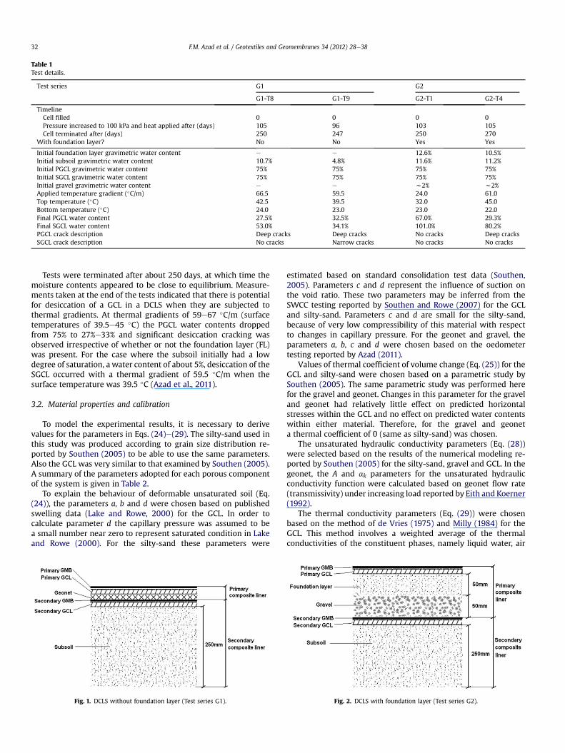
Table 1Test details.
Test series G1 G2
G1-T8 G1-T9 G2-T1 G2-T4
TimelineCell filled 0 0 0 0Pressure increased to 100 kPa and heat applied after (days) 105 96 103 105Cell terminated after (days) 250 247 250 270
With foundation layer? No No Yes Yes
Initial foundation layer gravimetric water content e e 12.6% 10.5%Initial subsoil gravimetric water content 10.7% 4.8% 11.6% 11.2%Initial PGCL gravimetric water content 75% 75% 75% 75%Initial SGCL gravimetric water content 75% 75% 75% 75%Initial gravel gravimetric water content e e w2% w2%Applied temperature gradient (�C/m) 66.5 59.5 24.0 61.0Top temperature (�C) 42.5 39.5 32.0 45.0Bottom temperature (�C) 24.0 23.0 23.0 22.0Final PGCL water content 27.5% 32.5% 67.0% 29.3%Final SGCL water content 53.0% 34.1% 101.0% 80.2%PGCL crack description Deep cracks Deep cracks No cracks Deep cracksSGCL crack description No cracks Narrow cracks No cracks No cracks
F.M. Azad et al. / Geotextiles and Geomembranes 34 (2012) 28e3832
Tests were terminated after about 250 days, at which time themoisture contents appeared to be close to equilibrium. Measure-ments taken at the end of the tests indicated that there is potentialfor desiccation of a GCL in a DCLS when they are subjected tothermal gradients. At thermal gradients of 59e67 �C/m (surfacetemperatures of 39.5e45 �C) the PGCL water contents droppedfrom 75% to 27%e33% and significant desiccation cracking wasobserved irrespective of whether or not the foundation layer (FL)was present. For the case where the subsoil initially had a lowdegree of saturation, a water content of about 5%, desiccation of theSGCL occurred with a thermal gradient of 59.5 �C/m when thesurface temperature was 39.5 �C (Azad et al., 2011).
3.2. Material properties and calibration
To model the experimental results, it is necessary to derivevalues for the parameters in Eqs. (24)e(29). The silty-sand used inthis study was produced according to grain size distribution re-ported by Southen (2005) to be able to use the same parameters.Also the GCL was very similar to that examined by Southen (2005).A summary of the parameters adopted for each porous componentof the system is given in Table 2.
To explain the behaviour of deformable unsaturated soil (Eq.(24)), the parameters a, b and d were chosen based on publishedswelling data (Lake and Rowe, 2000) for the GCL. In order tocalculate parameter d the capillary pressure was assumed to bea small number near zero to represent saturated condition in Lakeand Rowe (2000). For the silty-sand these parameters were
Fig. 1. DCLS without foundation layer (Test series G1).
estimated based on standard consolidation test data (Southen,2005). Parameters c and d represent the influence of suction onthe void ratio. These two parameters may be inferred from theSWCC testing reported by Southen and Rowe (2007) for the GCLand silty-sand. Parameters c and d are small for the silty-sand,because of very low compressibility of this material with respectto changes in capillary pressure. For the geonet and gravel, theparameters a, b, c and d were chosen based on the oedometertesting reported by Azad (2011).
Values of thermal coefficient of volume change (Eq. (25)) for theGCL and silty-sand were chosen based on a parametric study bySouthen (2005). The same parametric study was performed herefor the gravel and geonet. Changes in this parameter for the graveland geonet had relatively little effect on predicted horizontalstresses within the GCL and no effect on predicted water contentswithin either material. Therefore, for the gravel and geoneta thermal coefficient of 0 (same as silty-sand) was chosen.
The unsaturated hydraulic conductivity parameters (Eq. (28))were selected based on the results of the numerical modeling re-ported by Southen (2005) for the silty-sand, gravel and GCL. In thegeonet, the A and ak parameters for the unsaturated hydraulicconductivity function were calculated based on geonet flow rate(transmissivity) under increasing load reported by Eith and Koerner(1992).
The thermal conductivity parameters (Eq. (29)) were chosenbased on the method of de Vries (1975) and Milly (1984) for theGCL. This method involves a weighted average of the thermalconductivities of the constituent phases, namely liquid water, air
Fig. 2. DCLS with foundation layer (Test series G2).
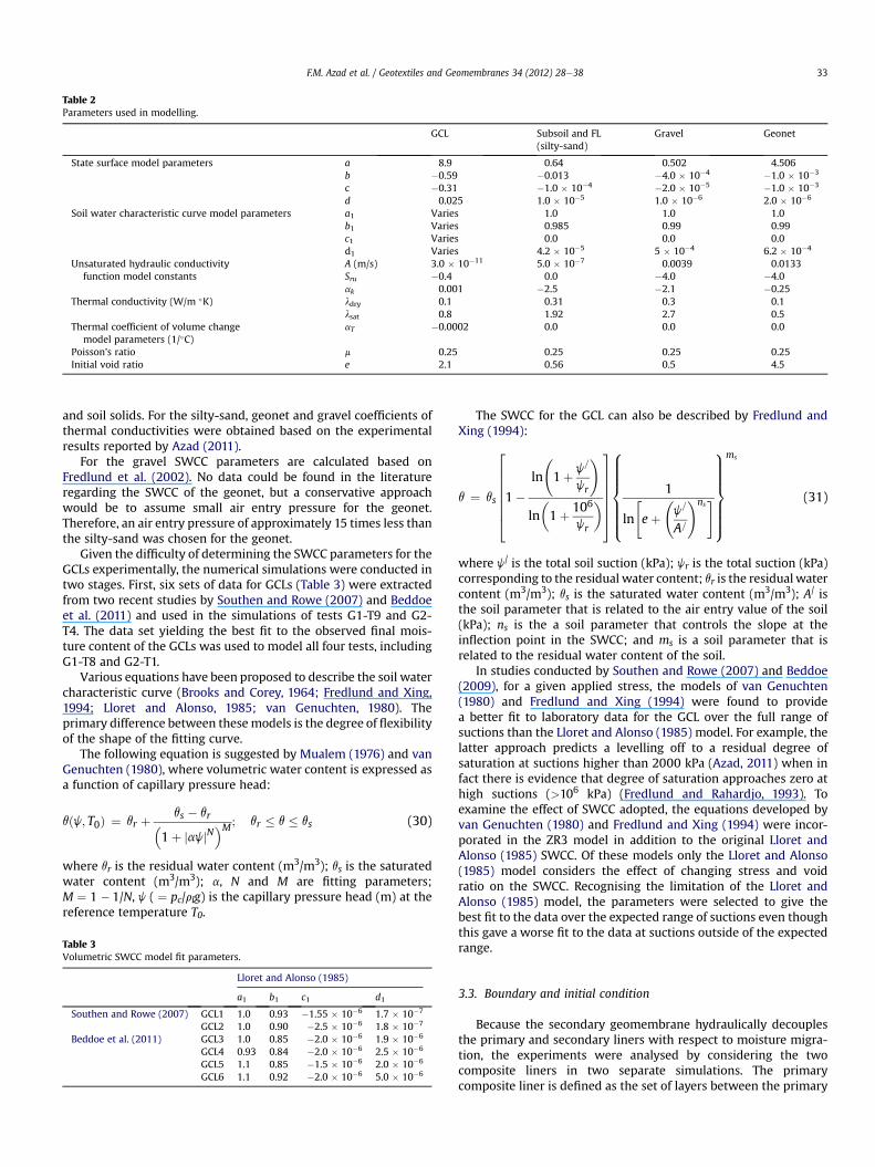
Table 2Parameters used in modelling.
GCL Subsoil and FL(silty-sand)
Gravel Geonet
State surface model parameters a 8.9 0.64 0.502 4.506b �0.59 �0.013 �4.0 � 10�4 �1.0 � 10�3
c �0.31 �1.0 � 10�4 �2.0 � 10�5 �1.0 � 10�3
d 0.025 1.0 � 10�5 1.0 � 10�6 2.0 � 10�6
Soil water characteristic curve model parameters a1 Varies 1.0 1.0 1.0b1 Varies 0.985 0.99 0.99c1 Varies 0.0 0.0 0.0d1 Varies 4.2 � 10�5 5 � 10�4 6.2 � 10�4
Unsaturated hydraulic conductivityfunction model constants
A (m/s) 3.0 � 10�11 5.0 � 10�7 0.0039 0.0133Sru �0.4 0.0 �4.0 �4.0ak 0.001 �2.5 �2.1 �0.25
Thermal conductivity (W/m �K) ldry 0.1 0.31 0.3 0.1lsat 0.8 1.92 2.7 0.5
Thermal coefficient of volume changemodel parameters (1/�C)
aT �0.0002 0.0 0.0 0.0
Poisson’s ratio m 0.25 0.25 0.25 0.25Initial void ratio e 2.1 0.56 0.5 4.5
F.M. Azad et al. / Geotextiles and Geomembranes 34 (2012) 28e38 33
and soil solids. For the silty-sand, geonet and gravel coefficients ofthermal conductivities were obtained based on the experimentalresults reported by Azad (2011).
For the gravel SWCC parameters are calculated based onFredlund et al. (2002). No data could be found in the literatureregarding the SWCC of the geonet, but a conservative approachwould be to assume small air entry pressure for the geonet.Therefore, an air entry pressure of approximately 15 times less thanthe silty-sand was chosen for the geonet.
Given the difficulty of determining the SWCC parameters for theGCLs experimentally, the numerical simulations were conducted intwo stages. First, six sets of data for GCLs (Table 3) were extractedfrom two recent studies by Southen and Rowe (2007) and Beddoeet al. (2011) and used in the simulations of tests G1-T9 and G2-T4. The data set yielding the best fit to the observed final mois-ture content of the GCLs was used to model all four tests, includingG1-T8 and G2-T1.
Various equations have been proposed to describe the soil watercharacteristic curve (Brooks and Corey, 1964; Fredlund and Xing,1994; Lloret and Alonso, 1985; van Genuchten, 1980). Theprimary difference between thesemodels is the degree of flexibilityof the shape of the fitting curve.
The following equation is suggested by Mualem (1976) and vanGenuchten (1980), where volumetric water content is expressed asa function of capillary pressure head:
qðj; T0Þ ¼ qr þ qs � qr�1þ jajjN
�M; qr � q � qs (30)
where qr is the residual water content (m3/m3); qs is the saturatedwater content (m3/m3); a, N and M are fitting parameters;M ¼ 1 � 1/N, j ( ¼ pc/rlg) is the capillary pressure head (m) at thereference temperature T0.
Table 3Volumetric SWCC model fit parameters.
Lloret and Alonso (1985)
a1 b1 c1 d1
Southen and Rowe (2007) GCL1 1.0 0.93 �1.55 � 10�6 1.7 � 10�7
GCL2 1.0 0.90 �2.5 � 10�6 1.8 � 10�7
Beddoe et al. (2011) GCL3 1.0 0.85 �2.0 � 10�6 1.9 � 10�6
GCL4 0.93 0.84 �2.0 � 10�6 2.5 � 10�6
GCL5 1.1 0.85 �1.5 � 10�6 2.0 � 10�6
GCL6 1.1 0.92 �2.0 � 10�6 5.0 � 10�6
The SWCC for the GCL can also be described by Fredlund andXing (1994):
q ¼ qs
266666641�
ln
1þ j=
jr
!
ln�1þ 106
jr
�
37777775
8>>>>>><>>>>>>:
1
ln
"eþ
j=
A=
!ns#
9>>>>>>=>>>>>>;
ms
(31)
where j/ is the total soil suction (kPa); jr is the total suction (kPa)corresponding to the residual water content; qr is the residual watercontent (m3/m3); qs is the saturated water content (m3/m3); A/ isthe soil parameter that is related to the air entry value of the soil(kPa); ns is the a soil parameter that controls the slope at theinflection point in the SWCC; and ms is a soil parameter that isrelated to the residual water content of the soil.
In studies conducted by Southen and Rowe (2007) and Beddoe(2009), for a given applied stress, the models of van Genuchten(1980) and Fredlund and Xing (1994) were found to providea better fit to laboratory data for the GCL over the full range ofsuctions than the Lloret and Alonso (1985) model. For example, thelatter approach predicts a levelling off to a residual degree ofsaturation at suctions higher than 2000 kPa (Azad, 2011) when infact there is evidence that degree of saturation approaches zero athigh suctions (>106 kPa) (Fredlund and Rahardjo, 1993). Toexamine the effect of SWCC adopted, the equations developed byvan Genuchten (1980) and Fredlund and Xing (1994) were incor-porated in the ZR3 model in addition to the original Lloret andAlonso (1985) SWCC. Of these models only the Lloret and Alonso(1985) model considers the effect of changing stress and voidratio on the SWCC. Recognising the limitation of the Lloret andAlonso (1985) model, the parameters were selected to give thebest fit to the data over the expected range of suctions even thoughthis gave a worse fit to the data at suctions outside of the expectedrange.
3.3. Boundary and initial condition
Because the secondary geomembrane hydraulically decouplesthe primary and secondary liners with respect to moisture migra-tion, the experiments were analysed by considering the twocomposite liners in two separate simulations. The primarycomposite liner is defined as the set of layers between the primary
Fig. 3. Measured and predicted PGCL gravimetric water contents for Test G1-T9.
F.M. Azad et al. / Geotextiles and Geomembranes 34 (2012) 28e3834
and secondary GMB. The secondary composite liner is the set oflayers between the secondary GMB and the bottom boundary,including SGCL and subsoil (Figs. 1 and 2). The GMBs were notexplicitly included in the model. Instead, GMBs were considered ashydraulic and air flux barriers represented by the boundarycondition described below. The thickness of each layer, totalnumber of one-dimensional two-node elements and number ofelements in each layer are given in Table 4. To ensure numericalconvergence, analyses were performed using different levels ofmesh refinement. Finally, the adopted mesh had 70 elements overthe primary composite liner of test series G1 and 160 elements forthe other composite liners. All elements were uniformly distributedwithin a layer.
The boundary conditions at the top of both composite linerswere zero air flux, zero moisture flux (due to the presence of theoverlying GMB), a stress increase ðDsÞ of 100 kPa at the appropriatetime and prescribed temperature. The boundary conditions at thebottom of the subsoil below both composite liners were zero airflux, zero moisture flux, zero displacement and a prescribedtemperature.
It was assumed that the temperature of the waste materialincreased immediately after landfilling so ZR3 was first run withthe boundary conditions for the isothermal stage then the resultswere used as initial conditions for the non-isothermal condition. Itwas found that while the temperature reached a steady-statewithin hours to days, the moisture redistribution requires muchlonger (100e260 days) to reach equilibrium. In addition, it wasfound that, for the liner materials studied, the temperatureprofile at steady-state was not very sensitive to the thermal prop-erties of the liner materials (Azad, 2011). Therefore in the presentanalysis, it was assumed that: (a) the temperature was constant atthe steady-state values, (b) the thermal conductivities were inde-pendent of the degree of saturation.
The temperature profile at steady-state was calculated sepa-rately by solving the heat conduction equation using Comsol Mul-tiphysics software and the thermal diffusivities reported by Azad(2011). It was then included as initial and boundary conditionsfor ZR3 simulation.
4. Results
4.1. Model calibration
The SWCC fitting parameters are listed in Table 3. Theseparameters vary between GCL types. This is likely due to the highdependence of the SWCC on the susceptibility of a given product tothe pullout of needle-punched fibres. The difference in themagnitude of parameter d1 (air-entry value) between these two
Table 4Thickness of barrier components and number of elements in each layer.
Test G1-T8 and G1-T9
Layers Thickness (mm)
Primary composite liner PGCL 8Geonet 6FL e
e
Gravel e
Total 14Secondary composite liner SGCL 8
Subsoil 2575
150Total 258
(negative compressive).
groups of studies is probably due to ameasurement error as a resultof the lack of contact between the GCL and the porousmembrane ofthe pressure plate apparatus reported during the experimentsconducted by Southen and Rowe (2007). The small differences inthe parameter c1 are due to differences in residual water contents indifferent products.
Themeasured and predicted PGCL gravimetric water contents atthe termination of Test G1-T9 are compared in Fig. 3. For this test,the PGCL exhibited a significant decrease inwater content from 75%to 32.5% whereupon desiccation cracking was observed at thetermination of the test. It may be seen from Fig. 3 that the prop-erties of GCL products can affect the predicted final GCL moisturecontent. The best fit to the experimental data was for GCL3parameters (which is the GCLmost similar to that tested in terms ofhow the GCL was manufactured). It appears that the ZR3 modelover predicted the water content in this GCL. The reason for thisdiscrepancy is discussed in the next section.
Fig. 4 shows a similar comparison for the secondary compositeliner for test G1-T9. The upper portion of the figure depicts thebehaviour within the SGCL at an exaggerated scale, while the lowerportion depicts the response within the silty-sand subsoil. Predic-tions of gravimetric water content are in reasonable agreementwith experimentally obtained values. The best fit to the test resultswas achieved using the GCL3 and GCL5 parameters (which are theGCLs with a woven carrier but only GCL3 is thermally treated). Fortest G2-T4 the best fit was generated by data sets GCL3 and GCL1,for PGCL and SGCL, respectively. Thus, GCL3 data set is adopted(along with the other parameters listed in Table 2).
The SWCC models of van Genuchten (1980) and Fredlund andXing (1994) were also incorporated into the ZR3 model as alter-natives to the SWCC proposed by Lloret and Alonso (1985). Thewater contents predicted in G1-T9 using Lloret and Alonso (1985)are compared with those based on the two alternative models inFigs. 5 and 6 for the PGCL and the SGCL of G1-T9, respectively. Lloretand Alonso (1985) gives a better prediction of the final moisturecontents. This is most probably due to the fact that Fredlund andXing (1994) and van Genuchten (1980) models do not consider
G2-T1 and G2-T4
Number of elements Thickness (mm) Number of elements
40 8 4030 e e
e 25 50e 25 25e 50 4570 108 16040 8 4050 25 5025 75 2545 150 45
160 258 160
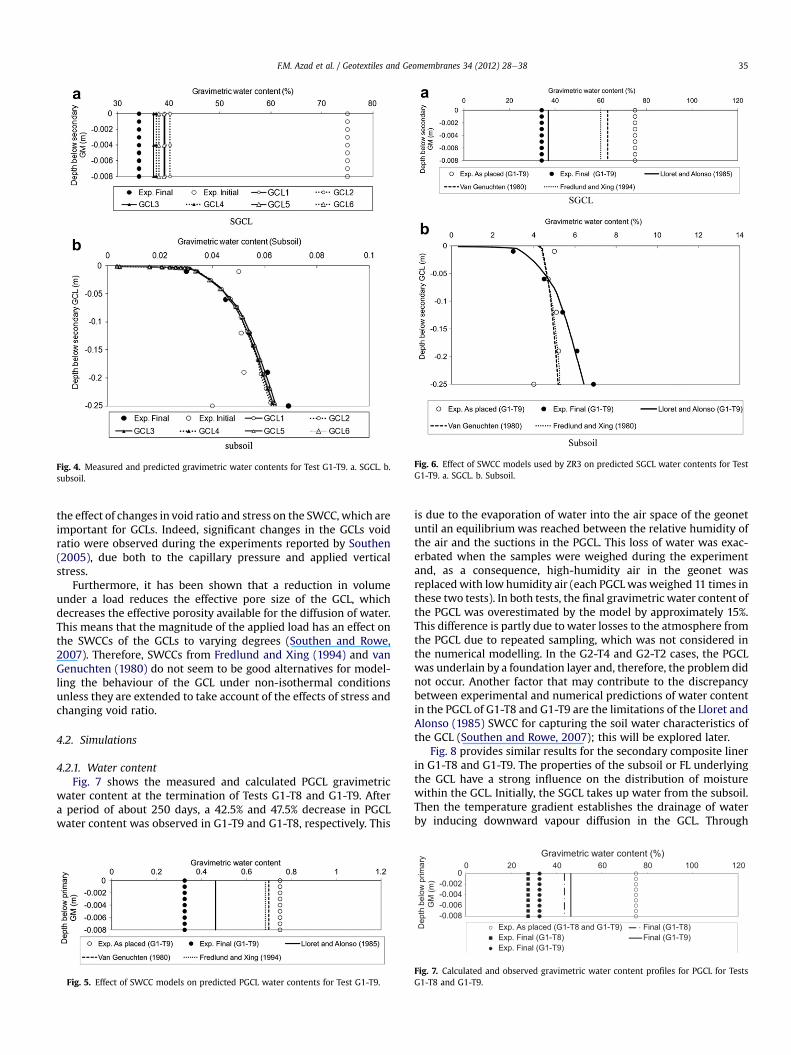
Fig. 6. Effect of SWCC models used by ZR3 on predicted SGCL water contents for TestG1-T9. a. SGCL. b. Subsoil.
Fig. 4. Measured and predicted gravimetric water contents for Test G1-T9. a. SGCL. b.subsoil.
F.M. Azad et al. / Geotextiles and Geomembranes 34 (2012) 28e38 35
the effect of changes in void ratio and stress on the SWCC, which areimportant for GCLs. Indeed, significant changes in the GCLs voidratio were observed during the experiments reported by Southen(2005), due both to the capillary pressure and applied verticalstress.
Furthermore, it has been shown that a reduction in volumeunder a load reduces the effective pore size of the GCL, whichdecreases the effective porosity available for the diffusion of water.This means that the magnitude of the applied load has an effect onthe SWCCs of the GCLs to varying degrees (Southen and Rowe,2007). Therefore, SWCCs from Fredlund and Xing (1994) and vanGenuchten (1980) do not seem to be good alternatives for model-ling the behaviour of the GCL under non-isothermal conditionsunless they are extended to take account of the effects of stress andchanging void ratio.
4.2. Simulations
4.2.1. Water contentFig. 7 shows the measured and calculated PGCL gravimetric
water content at the termination of Tests G1-T8 and G1-T9. Aftera period of about 250 days, a 42.5% and 47.5% decrease in PGCLwater content was observed in G1-T9 and G1-T8, respectively. This
Fig. 5. Effect of SWCC models on predicted PGCL water contents for Test G1-T9.
is due to the evaporation of water into the air space of the geonetuntil an equilibrium was reached between the relative humidity ofthe air and the suctions in the PGCL. This loss of water was exac-erbated when the samples were weighed during the experimentand, as a consequence, high-humidity air in the geonet wasreplacedwith low humidity air (each PGCLwasweighed 11 times inthese two tests). In both tests, the final gravimetric water content ofthe PGCL was overestimated by the model by approximately 15%.This difference is partly due to water losses to the atmosphere fromthe PGCL due to repeated sampling, which was not considered inthe numerical modelling. In the G2-T4 and G2-T2 cases, the PGCLwas underlain by a foundation layer and, therefore, the problem didnot occur. Another factor that may contribute to the discrepancybetween experimental and numerical predictions of water contentin the PGCL of G1-T8 and G1-T9 are the limitations of the Lloret andAlonso (1985) SWCC for capturing the soil water characteristics ofthe GCL (Southen and Rowe, 2007); this will be explored later.
Fig. 8 provides similar results for the secondary composite linerin G1-T8 and G1-T9. The properties of the subsoil or FL underlyingthe GCL have a strong influence on the distribution of moisturewithin the GCL. Initially, the SGCL takes up water from the subsoil.Then the temperature gradient establishes the drainage of waterby inducing downward vapour diffusion in the GCL. Through
-0.008-0.006-0.004-0.002
00 20 40 60 80 100 120
Dep
th b
elow
prim
ary
GM
(m)
Gravimetric water content (%)
Exp. As placed (G1-T8 and G1-T9) Final (G1-T8)Exp. Final (G1-T8) Final (G1-T9)Exp. Final (G1-T9)
Fig. 7. Calculated and observed gravimetric water content profiles for PGCL for TestsG1-T8 and G1-T9.
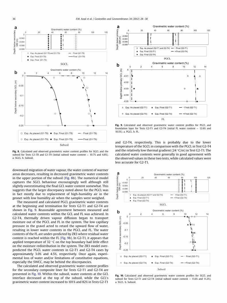
Fig. 9. Calculated and observed gravimetric water content profiles for PGCL andfoundation layer for Tests G2-T1 and G2-T4 (initial FL water content ¼ 12.6% and10.5%). a. PGCL. b. FL.
-0.008
-0.006
-0.004
-0.002
00 20 40 60 80 100 120
Dep
th b
elow
sec
onda
ry
GM
(m)
Gravimetric water content (%)
Exp. As placed (G1-T8 and G1-T9) Final (G1-T8)
Exp. Final (G1-T8) Final (G1-T9)
Exp. Final (G1-T9)
SGCL
-0.25
-0.2
-0.15
-0.1
-0.05
00 2 4 6 8 10 12 14
Dep
th b
elow
sec
onda
ry G
CL
(m)
Gravimetric water content (%)
Exp. As placed (G1-T8) Exp. Final (G1-T8) Final (G1-T8)
Exp. As placed (G1-T9) Exp. Final (G1-T9) Final (G1-T9)
Subsoil
a
b
Fig. 8. Calculated and observed gravimetric water content profiles for SGCL and thesubsoil for Tests G1-T8 and G1-T9 (initial subsoil water content ¼ 10.7% and 4.8%).a. SGCL. b. Subsoil.
-0.008-0.006-0.004-0.002
00 20 40 60 80 100 120
Dep
th b
elow
sec
onda
ry
GM
(m)
Gravimetric water content (%)
Exp. As placed (G2-T1 and G2-T4) Final (G2-T1)Exp. Final (G2-T1) Final (G2-T4)Exp. Final (G2-T4)
SGCL
-0.25
-0.2
-0.15
-0.1
-0.05
00 2 4 6 8 10 12 14
Dep
th b
elow
sec
onda
ry G
CL
(m)
Gravimetric water content (%)
Exp. As placed (G2-T1) Exp. Final (G2-T1) Final (G2-T1)
Exp. As placed (G2-T4) Exp. Final (G2-T4) Final (G2-T4)
Subsoil
a
b
Fig. 10. Calculated and observed gravimetric water content profiles for SGCL andsubsoil for Tests G2-T1 and G2-T4 (initial subsoil water content ¼ 11.6% and 11.2%).a. SGCL. b. Subsoil.
F.M. Azad et al. / Geotextiles and Geomembranes 34 (2012) 28e3836
downward migration of water vapour, the water content of warmerareas decreases, resulting in decreased gravimetric water contentsin the upper portion of the subsoil (Fig. 8b). The numerical modelcaptures the SGCL behaviour encouragingly well although stillslightly overestimating the final GCL water content somewhat. Thissuggests that the larger discrepancy noted above for the PGCL wasin fact mostly due to replacement of high-humidity air in thegeonet with low humidity air when the samples were weighed.
The measured and calculated PGCL gravimetric water contentsat the beginning and termination for Tests G2-T1 and G2-T4 areshown in Fig. 9. Reasonable agreement between measured andcalculated water contents within the GCL and FL was achieved. InG2-T4, thermally driven vapour diffusion began to transportmoisture out of the PGCL and FL in the system. The low capillarypressure in the gravel acted to retard the upward flow of water,resulting in lower water contents in the PGCL and FL. The watercontents of the FL are under-predicted by ZR3 where residual watercontent is reached within the FL (Fig. 9b). In G2-T1, it appears thatapplied temperature of 32 �C on the top boundary had little effecton the moisture redistribution in the system. The ZR3 model over-predicted the PGCL water contents in G2-T1 and G2-T4 cases byapproximately 3.0% and 4.5%, respectively. Once again, experi-mental loss of water and/or limitations of constitutive equations,especially the SWCC, may be behind the discrepancies.
The calculated and observed gravimetric water content profilesfor the secondary composite liner for Tests G2-T1 and G2-T4 arepresented in Fig. 10. Within the subsoil, water contents at the GCLinterface decreased at the top of the subsoil, while the GCL’sgravimetric water content increased to 101% and 82% in Tests G2-T1
and G2-T4, respectively. This is probably due to the lowertemperature of the SGCL in comparisonwith the PGCL in Test G2-T4and the relatively low thermal gradient (24 �C/m) in Test G2-T1. Thecalculated water contents were generally in good agreement withthe observed values in these two tests, while calculated values wereless accurate for G2-T1.
a
b
Fig. 13. Net total horizontal stress profiles for SGCL and subsoil (G1-T8 and G1-T9)(negative compressive). a. SGCL. b. Subsoil.
Fig. 11. Net total horizontal stress profiles for PGCL (G1-T8 and G1-T9).
F.M. Azad et al. / Geotextiles and Geomembranes 34 (2012) 28e38 37
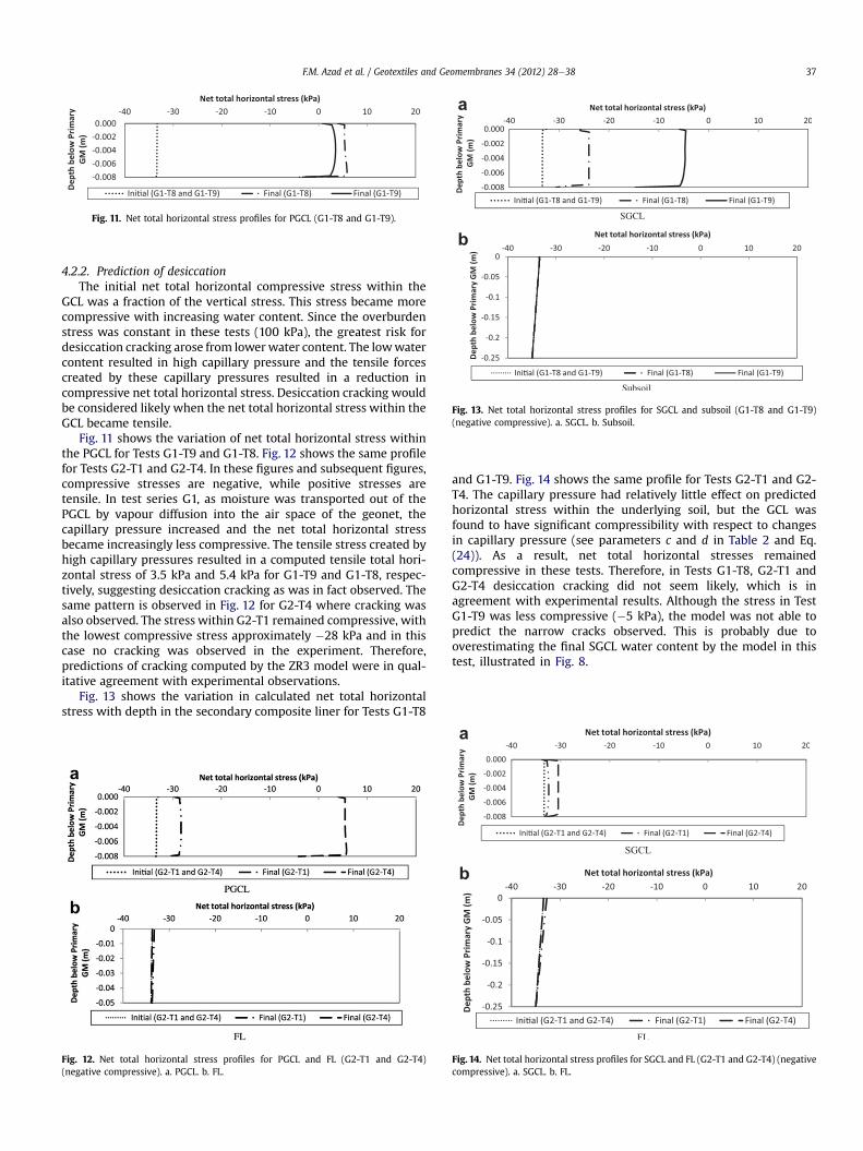
4.2.2. Prediction of desiccationThe initial net total horizontal compressive stress within the
GCL was a fraction of the vertical stress. This stress became morecompressive with increasing water content. Since the overburdenstress was constant in these tests (100 kPa), the greatest risk fordesiccation cracking arose from lowerwater content. The lowwatercontent resulted in high capillary pressure and the tensile forcescreated by these capillary pressures resulted in a reduction incompressive net total horizontal stress. Desiccation cracking wouldbe considered likely when the net total horizontal stress within theGCL became tensile.
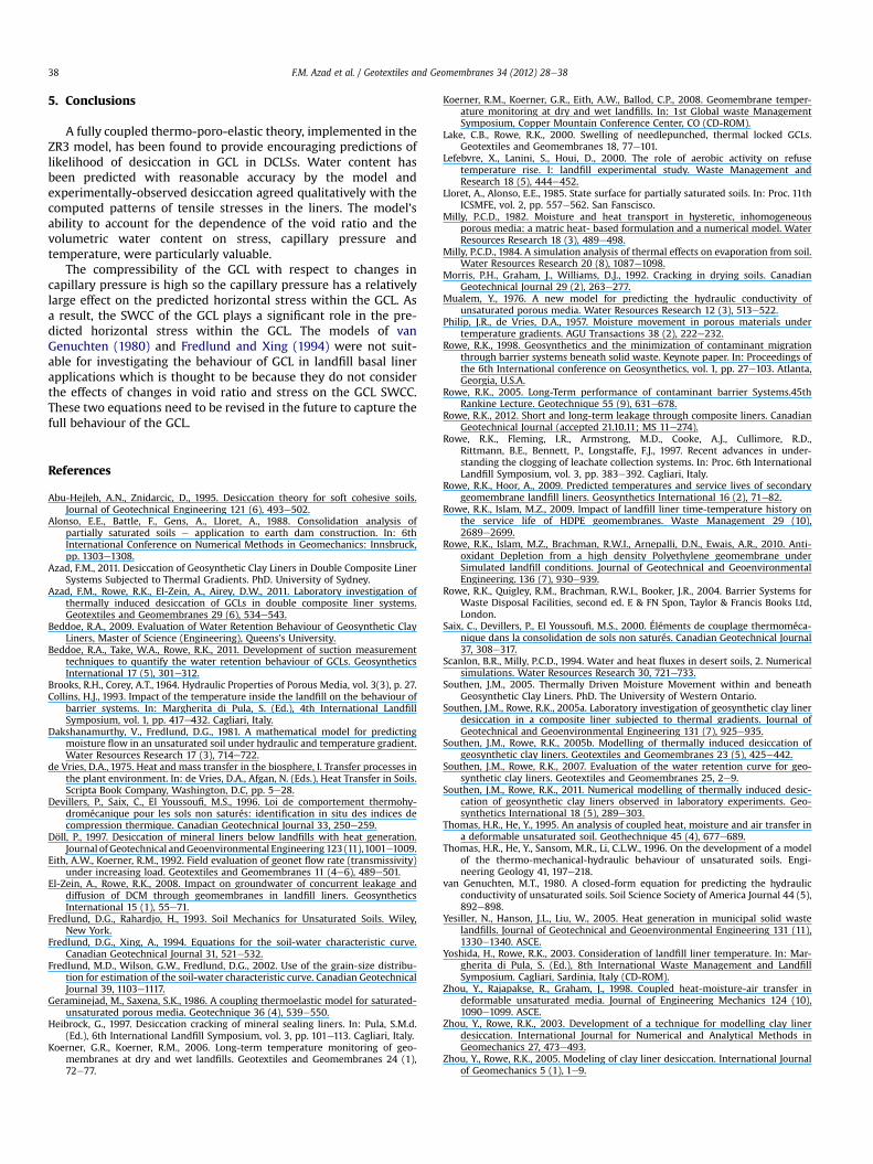
Fig. 11 shows the variation of net total horizontal stress withinthe PGCL for Tests G1-T9 and G1-T8. Fig. 12 shows the same profilefor Tests G2-T1 and G2-T4. In these figures and subsequent figures,compressive stresses are negative, while positive stresses aretensile. In test series G1, as moisture was transported out of thePGCL by vapour diffusion into the air space of the geonet, thecapillary pressure increased and the net total horizontal stressbecame increasingly less compressive. The tensile stress created byhigh capillary pressures resulted in a computed tensile total hori-zontal stress of 3.5 kPa and 5.4 kPa for G1-T9 and G1-T8, respec-tively, suggesting desiccation cracking as was in fact observed. Thesame pattern is observed in Fig. 12 for G2-T4 where cracking wasalso observed. The stress within G2-T1 remained compressive, withthe lowest compressive stress approximately �28 kPa and in thiscase no cracking was observed in the experiment. Therefore,predictions of cracking computed by the ZR3 model were in qual-itative agreement with experimental observations.
Fig. 13 shows the variation in calculated net total horizontalstress with depth in the secondary composite liner for Tests G1-T8
Fig. 12. Net total horizontal stress profiles for PGCL and FL (G2-T1 and G2-T4)(negative compressive). a. PGCL. b. FL.
and G1-T9. Fig. 14 shows the same profile for Tests G2-T1 and G2-T4. The capillary pressure had relatively little effect on predictedhorizontal stress within the underlying soil, but the GCL wasfound to have significant compressibility with respect to changesin capillary pressure (see parameters c and d in Table 2 and Eq.(24)). As a result, net total horizontal stresses remainedcompressive in these tests. Therefore, in Tests G1-T8, G2-T1 andG2-T4 desiccation cracking did not seem likely, which is inagreement with experimental results. Although the stress in TestG1-T9 was less compressive (�5 kPa), the model was not able topredict the narrow cracks observed. This is probably due tooverestimating the final SGCL water content by the model in thistest, illustrated in Fig. 8.
a
b
Fig. 14. Net total horizontal stress profiles for SGCL and FL (G2-T1 and G2-T4) (negativecompressive). a. SGCL. b. FL.
F.M. Azad et al. / Geotextiles and Geomembranes 34 (2012) 28e3838
5. Conclusions
A fully coupled thermo-poro-elastic theory, implemented in theZR3 model, has been found to provide encouraging predictions oflikelihood of desiccation in GCL in DCLSs. Water content hasbeen predicted with reasonable accuracy by the model andexperimentally-observed desiccation agreed qualitatively with thecomputed patterns of tensile stresses in the liners. The model’sability to account for the dependence of the void ratio and thevolumetric water content on stress, capillary pressure andtemperature, were particularly valuable.
The compressibility of the GCL with respect to changes incapillary pressure is high so the capillary pressure has a relativelylarge effect on the predicted horizontal stress within the GCL. Asa result, the SWCC of the GCL plays a significant role in the pre-dicted horizontal stress within the GCL. The models of vanGenuchten (1980) and Fredlund and Xing (1994) were not suit-able for investigating the behaviour of GCL in landfill basal linerapplications which is thought to be because they do not considerthe effects of changes in void ratio and stress on the GCL SWCC.These two equations need to be revised in the future to capture thefull behaviour of the GCL.
References
Abu-Hejleh, A.N., Znidarcic, D., 1995. Desiccation theory for soft cohesive soils.Journal of Geotechnical Engineering 121 (6), 493e502.
Alonso, E.E., Battle, F., Gens, A., Lloret, A., 1988. Consolidation analysis ofpartially saturated soils e application to earth dam construction. In: 6thInternational Conference on Numerical Methods in Geomechanics: Innsbruck,pp. 1303e1308.
Azad, F.M., 2011. Desiccation of Geosynthetic Clay Liners in Double Composite LinerSystems Subjected to Thermal Gradients. PhD. University of Sydney.
Azad, F.M., Rowe, R.K., El-Zein, A., Airey, D.W., 2011. Laboratory investigation ofthermally induced desiccation of GCLs in double composite liner systems.Geotextiles and Geomembranes 29 (6), 534e543.
Beddoe, R.A., 2009. Evaluation of Water Retention Behaviour of Geosynthetic ClayLiners, Master of Science (Engineering), Queens’s University.
Beddoe, R.A., Take, W.A., Rowe, R.K., 2011. Development of suction measurementtechniques to quantify the water retention behaviour of GCLs. GeosyntheticsInternational 17 (5), 301e312.
Brooks, R.H., Corey, A.T., 1964. Hydraulic Properties of Porous Media, vol. 3(3), p. 27.Collins, H.J., 1993. Impact of the temperature inside the landfill on the behaviour of
barrier systems. In: Margherita di Pula, S. (Ed.), 4th International LandfillSymposium, vol. 1, pp. 417e432. Cagliari, Italy.
Dakshanamurthy, V., Fredlund, D.G., 1981. A mathematical model for predictingmoisture flow in an unsaturated soil under hydraulic and temperature gradient.Water Resources Research 17 (3), 714e722.
de Vries, D.A., 1975. Heat and mass transfer in the biosphere, I. Transfer processes inthe plant environment. In: de Vries, D.A., Afgan, N. (Eds.), Heat Transfer in Soils.Scripta Book Company, Washington, D.C, pp. 5e28.
Devillers, P., Saix, C., El Youssoufi, M.S., 1996. Loi de comportement thermohy-dromécanique pour les sols non saturés: identification in situ des indices decompression thermique. Canadian Geotechnical Journal 33, 250e259.
Döll, P., 1997. Desiccation of mineral liners below landfills with heat generation.Journal of Geotechnical andGeoenvironmental Engineering 123 (11),1001e1009.
Eith, A.W., Koerner, R.M., 1992. Field evaluation of geonet flow rate (transmissivity)under increasing load. Geotextiles and Geomembranes 11 (4e6), 489e501.
El-Zein, A., Rowe, R.K., 2008. Impact on groundwater of concurrent leakage anddiffusion of DCM through geomembranes in landfill liners. GeosyntheticsInternational 15 (1), 55e71.
Fredlund, D.G., Rahardjo, H., 1993. Soil Mechanics for Unsaturated Soils. Wiley,New York.
Fredlund, D.G., Xing, A., 1994. Equations for the soil-water characteristic curve.Canadian Geotechnical Journal 31, 521e532.
Fredlund, M.D., Wilson, G.W., Fredlund, D.G., 2002. Use of the grain-size distribu-tion for estimation of the soil-water characteristic curve. Canadian GeotechnicalJournal 39, 1103e1117.
Geraminejad, M., Saxena, S.K., 1986. A coupling thermoelastic model for saturated-unsaturated porous media. Geotechnique 36 (4), 539e550.
Heibrock, G., 1997. Desiccation cracking of mineral sealing liners. In: Pula, S.M.d.(Ed.), 6th International Landfill Symposium, vol. 3, pp. 101e113. Cagliari, Italy.
Koerner, G.R., Koerner, R.M., 2006. Long-term temperature monitoring of geo-membranes at dry and wet landfills. Geotextiles and Geomembranes 24 (1),72e77.
Koerner, R.M., Koerner, G.R., Eith, A.W., Ballod, C.P., 2008. Geomembrane temper-ature monitoring at dry and wet landfills. In: 1st Global waste ManagementSymposium, Copper Mountain Conference Center, CO (CD-ROM).
Lake, C.B., Rowe, R.K., 2000. Swelling of needlepunched, thermal locked GCLs.Geotextiles and Geomembranes 18, 77e101.
Lefebvre, X., Lanini, S., Houi, D., 2000. The role of aerobic activity on refusetemperature rise. I: landfill experimental study. Waste Management andResearch 18 (5), 444e452.
Lloret, A., Alonso, E.E., 1985. State surface for partially saturated soils. In: Proc. 11thICSMFE, vol. 2, pp. 557e562. San Fanscisco.
Milly, P.C.D., 1982. Moisture and heat transport in hysteretic, inhomogeneousporous media: a matric heat- based formulation and a numerical model. WaterResources Research 18 (3), 489e498.
Milly, P.C.D., 1984. A simulation analysis of thermal effects on evaporation from soil.Water Resources Research 20 (8), 1087e1098.
Morris, P.H., Graham, J., Williams, D.J., 1992. Cracking in drying soils. CanadianGeotechnical Journal 29 (2), 263e277.
Mualem, Y., 1976. A new model for predicting the hydraulic conductivity ofunsaturated porous media. Water Resources Research 12 (3), 513e522.
Philip, J.R., de Vries, D.A., 1957. Moisture movement in porous materials undertemperature gradients. AGU Transactions 38 (2), 222e232.
Rowe, R.K., 1998. Geosynthetics and the minimization of contaminant migrationthrough barrier systems beneath solid waste. Keynote paper. In: Proceedings ofthe 6th International conference on Geosynthetics, vol. 1, pp. 27e103. Atlanta,Georgia, U.S.A.
Rowe, R.K., 2005. Long-Term performance of contaminant barrier Systems.45thRankine Lecture. Geotechnique 55 (9), 631e678.
Rowe, R.K., 2012. Short and long-term leakage through composite liners. CanadianGeotechnical Journal (accepted 21.10.11; MS 11e274).
Rowe, R.K., Fleming, I.R., Armstrong, M.D., Cooke, A.J., Cullimore, R.D.,Rittmann, B.E., Bennett, P., Longstaffe, F.J., 1997. Recent advances in under-standing the clogging of leachate collection systems. In: Proc. 6th InternationalLandfill Symposium, vol. 3, pp. 383e392. Cagliari, Italy.
Rowe, R.K., Hoor, A., 2009. Predicted temperatures and service lives of secondarygeomembrane landfill liners. Geosynthetics International 16 (2), 71e82.
Rowe, R.K., Islam, M.Z., 2009. Impact of landfill liner time-temperature history onthe service life of HDPE geomembranes. Waste Management 29 (10),2689e2699.
Rowe, R.K., Islam, M.Z., Brachman, R.W.I., Arnepalli, D.N., Ewais, A.R., 2010. Anti-oxidant Depletion from a high density Polyethylene geomembrane underSimulated landfill conditions. Journal of Geotechnical and GeoenvironmentalEngineering. 136 (7), 930e939.
Rowe, R.K., Quigley, R.M., Brachman, R.W.I., Booker, J.R., 2004. Barrier Systems forWaste Disposal Facilities, second ed. E & FN Spon, Taylor & Francis Books Ltd,London.
Saix, C., Devillers, P., El Youssoufi, M.S., 2000. Éléments de couplage thermoméca-nique dans la consolidation de sols non saturés. Canadian Geotechnical Journal37, 308e317.
Scanlon, B.R., Milly, P.C.D., 1994. Water and heat fluxes in desert soils, 2. Numericalsimulations. Water Resources Research 30, 721e733.
Southen, J.M., 2005. Thermally Driven Moisture Movement within and beneathGeosynthetic Clay Liners. PhD. The University of Western Ontario.
Southen, J.M., Rowe, R.K., 2005a. Laboratory investigation of geosynthetic clay linerdesiccation in a composite liner subjected to thermal gradients. Journal ofGeotechnical and Geoenvironmental Engineering 131 (7), 925e935.
Southen, J.M., Rowe, R.K., 2005b. Modelling of thermally induced desiccation ofgeosynthetic clay liners. Geotextiles and Geomembranes 23 (5), 425e442.
Southen, J.M., Rowe, R.K., 2007. Evaluation of the water retention curve for geo-synthetic clay liners. Geotextiles and Geomembranes 25, 2e9.
Southen, J.M., Rowe, R.K., 2011. Numerical modelling of thermally induced desic-cation of geosynthetic clay liners observed in laboratory experiments. Geo-synthetics International 18 (5), 289e303.
Thomas, H.R., He, Y., 1995. An analysis of coupled heat, moisture and air transfer ina deformable unsaturated soil. Geothechnique 45 (4), 677e689.
Thomas, H.R., He, Y., Sansom, M.R., Li, C.L.W., 1996. On the development of a modelof the thermo-mechanical-hydraulic behaviour of unsaturated soils. Engi-neering Geology 41, 197e218.
van Genuchten, M.T., 1980. A closed-form equation for predicting the hydraulicconductivity of unsaturated soils. Soil Science Society of America Journal 44 (5),892e898.
Yesiller, N., Hanson, J.L., Liu, W., 2005. Heat generation in municipal solid wastelandfills. Journal of Geotechnical and Geoenvironmental Engineering 131 (11),1330e1340. ASCE.
Yoshida, H., Rowe, R.K., 2003. Consideration of landfill liner temperature. In: Mar-gherita di Pula, S. (Ed.), 8th International Waste Management and LandfillSymposium. Cagliari, Sardinia, Italy (CD-ROM).
Zhou, Y., Rajapakse, R., Graham, J., 1998. Coupled heat-moisture-air transfer indeformable unsaturated media. Journal of Engineering Mechanics 124 (10),1090e1099. ASCE.
Zhou, Y., Rowe, R.K., 2003. Development of a technique for modelling clay linerdesiccation. International Journal for Numerical and Analytical Methods inGeomechanics 27, 473e493.
Zhou, Y., Rowe, R.K., 2005. Modeling of clay liner desiccation. International Journalof Geomechanics 5 (1), 1e9.
Related Documents