ICRA2003, Modelling of the human paralysed lower limb under FES 1 Abstract — The new generation of implanted neuroprostheses allows muscles to be controlled with fine accuracy, high selectivity and the repeatability of the muscle’s response can be achieved. Thus, the closed loop control of such systems becomes possible. The SUAW project succeeded in the implantation of an advanced neuroprosthetic device on two patients, but the movement generation remains open loop and is tuned empirically. Nevertheless, the good results obtained give us the opportunity to envisage the system evolves towards closed loop control and automatic synthesis of the stimulation patterns generating the desired movement. To achieve this goal, some preliminary researches have to be carried out, beginning with a specific modelling that can be used in the context of Functional Electrical Stimulation (FES). The main issues concern muscle modelling including the interaction with the skeleton, fatigue, FES parameters as inputs, and the identification of dynamic parameters, and afterwards, the motion synthesis and the closed loop control based on this model. Besides, the scientific approach is the same as in robotics so that the theoretical tools used in the control theory are the same and directly applicable. This paper describes the results obtained in the previous project SUAW and how we attempt, through the new project DEMAR, to enhance the global performances of the system. Index Terms — FES, implant, identification, model, paraplegia. 1 LIRMM, 161 Rue Ada F-34392 Montpellier Cedex 5 2 INRIA, UR Sophia Antipolis, 2004 Route des Lucioles, 06902 F- Sophia Antipolis 3 INRIA, UR Rhône Alpes, ZIRST, 655 Avenue de l’Europe, F-38330 Montbonnot 4 MXM, 2720 Chemin Saint Bernard, F-06224 Vallauris 5 Faculté de médecine de Montpellier, 1 Rue Ecole de médecine F- 34000 Montpellier I. INTRODUCTION UNCTIONAL Electrical Stimulation (FES) has been used for more than thirty years in order to restore movements in paraplegic and tetraplegic patients. External FES is used only for rehabilitation purposes in dedicated clinical centres. Implanted neuroprostheses then arose during the 80s using different approaches, for instance : i) epimysial and intra muscular stimulations [7], ii) neural stimulation [5], iii) distributed intramuscular stimulation unit BION TM , iv) and sacral roots stimulation [6]. Only one is commercially available for the upper limb, none for the lower limb and even abandoned for the last one. The SUAW project succeeded in a mixed implant with both neural and epimysial stimulations working together [8, 10]. Regarding the synthesis and the control of the movement very few complete results are available. Recent work has been carried out mainly with external FES [1, 2, 3, 4, 9]. Although the technique provides good results as regards reliability, repeatability and selectivity of muscle contraction, the movement is still generated with open loop control and the stimulation sequences are tuned empirically. To enhance the performances of the system, a control theory approach becomes necessary. Recent work has been carried out to explore the possibility of using the tools of the control theory. To do so, the first main obstacles remain modelling and sensors feedbacks. The present paper deals with the results obtained through the SUAW project, and within the new DEMAR project, how we attempt to introduce control theory to enhance results. II. BACKGROUND : SUAW PROJECT FIRST RESULTS A. Hardware and software developments The SUAW project began in 1996 with the following partners : IBM France was responsible for the ASIC development, Thomson France, for the RF transmission and extra discrete electronic design within the implant, MXM France, for the packaging and the final packaging of the implant, IBMT Germany, for the epimysial Modelling of the human paralysed lower limb under FES D. Guiraud 1,2 , P. Poignet 1 , P.B. Wieber 3 , H. El Makksoud 1 , F. Pierrot 1 , B. Brogliato 3 , P. Fraisse 1 , E. Dombre 1 , J.L. Divoux 4 , P. Rabischong 5 F inria-00390865, version 1 - 2 Jun 2009 Author manuscript, published in "IEEE International Conference on Robotics & Automation (2003)"

Welcome message from author
This document is posted to help you gain knowledge. Please leave a comment to let me know what you think about it! Share it to your friends and learn new things together.
Transcript
ICRA2003, Modelling of the human paralysed lower limb under FES
1
Abstract — The new generation of implanted
neuroprostheses allows muscles to be controlled with fine accuracy, high selectivity and the repeatability of the muscle’s response can be achieved. Thus, the closed loop control of such systems becomes possible. The SUAW project succeeded in the implantation of an advanced neuroprosthetic device on two patients, but the movement generation remains open loop and is tuned empirically. Nevertheless, the good results obtained give us the opportunity to envisage the system evolves towards closed loop control and automatic synthesis of the stimulation patterns generating the desired movement. To achieve this goal, some preliminary researches have to be carried out, beginning with a specific modelling that can be used in the context of Functional Electrical Stimulation (FES). The main issues concern muscle modelling including the interaction with the skeleton, fatigue, FES parameters as inputs, and the identification of dynamic parameters, and afterwards, the motion synthesis and the closed loop control based on this model. Besides, the scientific approach is the same as in robotics so that the theoretical tools used in the control theory are the same and directly applicable. This paper describes the results obtained in the previous project SUAW and how we attempt, through the new project DEMAR, to enhance the global performances of the system.
Index Terms — FES, implant, identification, model, paraplegia.
1LIRMM, 161 Rue Ada F-34392 Montpellier Cedex 5 2INRIA, UR Sophia Antipolis, 2004 Route des Lucioles, 06902 F-
Sophia Antipolis 3INRIA, UR Rhône Alpes, ZIRST, 655 Avenue de l’Europe, F-38330
Montbonnot 4MXM, 2720 Chemin Saint Bernard, F-06224 Vallauris 5Faculté de médecine de Montpellier, 1 Rue Ecole de médecine F-
34000 Montpellier
I. INTRODUCTION UNCTIONAL Electrical Stimulation (FES) has been
used for more than thirty years in order to restore movements in paraplegic and tetraplegic patients. External FES is used only for rehabilitation purposes in dedicated clinical centres. Implanted neuroprostheses then arose during the 80s using different approaches, for instance : i) epimysial and intra muscular stimulations [7], ii) neural stimulation [5], iii) distributed intramuscular stimulation unit BIONTM, iv) and sacral roots stimulation [6]. Only one is commercially available for the upper limb, none for the lower limb and even abandoned for the last one. The SUAW project succeeded in a mixed implant with both neural and epimysial stimulations working together [8, 10]. Regarding the synthesis and the control of the movement very few complete results are available. Recent work has been carried out mainly with external FES [1, 2, 3, 4, 9]. Although the technique provides good results as regards reliability, repeatability and selectivity of muscle contraction, the movement is still generated with open loop control and the stimulation sequences are tuned empirically. To enhance the performances of the system, a control theory approach becomes necessary. Recent work has been carried out to explore the possibility of using the tools of the control theory. To do so, the first main obstacles remain modelling and sensors feedbacks. The present paper deals with the results obtained through the SUAW project, and within the new DEMAR project, how we attempt to introduce control theory to enhance results.
II. BACKGROUND : SUAW PROJECT FIRST RESULTS
A. Hardware and software developments The SUAW project began in 1996 with the following
partners : IBM France was responsible for the ASIC development, Thomson France, for the RF transmission and extra discrete electronic design within the implant, MXM France, for the packaging and the final packaging of the implant, IBMT Germany, for the epimysial
Modelling of the human paralysed lower limb under FES
D. Guiraud1,2, P. Poignet1, P.B. Wieber3, H. El Makksoud1, F. Pierrot1, B. Brogliato3, P. Fraisse1, E. Dombre1, J.L. Divoux4, P. Rabischong5
F
inria
-003
9086
5, v
ersi
on 1
- 2
Jun
2009
Author manuscript, published in "IEEE International Conference on Robotics & Automation (2003)"
ICRA2003, Modelling of the human paralysed lower limb under FES
2
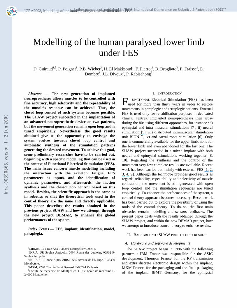
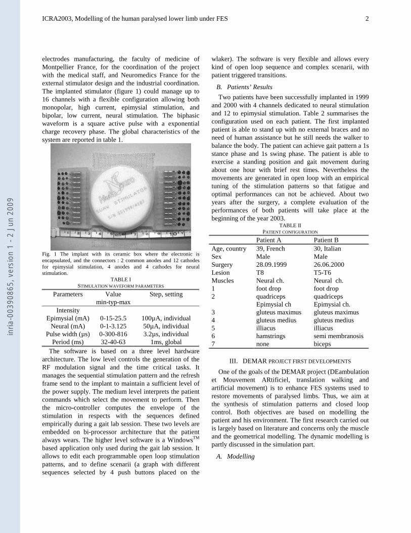
electrodes manufacturing, the faculty of medicine of Montpellier France, for the coordination of the project with the medical staff, and Neuromedics France for the external stimulator design and the industrial coordination. The implanted stimulator (figure 1) could manage up to 16 channels with a flexible configuration allowing both monopolar, high current, epimysial stimulation, and bipolar, low current, neural stimulation. The biphasic waveform is a square active pulse with a exponential charge recovery phase. The global characteristics of the system are reported in table 1.
Fig. 1 The implant with its ceramic box where the electronic is encapsulated, and the connectors : 2 common anodes and 12 cathodes for epimysial stimulation, 4 anodes and 4 cathodes for neural stimulation.
TABLE I STIMULATION WAVEFORM PARAMETERS
Parameters Value min-typ-max
Step, setting
Intensity Epimysial (mA)
Neural (mA)
0-15-25.5 0-1-3.125
100µA, individual 50µA, individual
Pulse width (µs) 0-300-816 3.2µs, individual Period (ms) 32-40-63 1ms, global
The software is based on a three level hardware architecture. The low level controls the generation of the RF modulation signal and the time critical tasks. It manages the sequential stimulation pattern and the refresh frame send to the implant to maintain a sufficient level of the power supply. The medium level interprets the patient commands which select the movement to perform. Then the micro-controller computes the envelope of the stimulation in respects with the sequences defined empirically during a gait lab session. These two levels are embedded on bi-processor architecture that the patient always wears. The higher level software is a WindowsTM based application only used during the gait lab session. It allows to edit each programmable open loop stimulation patterns, and to define scenarii (a graph with different sequences selected by 4 push buttons placed on the
wlaker). The software is very flexible and allows every kind of open loop sequence and complex scenarii, with patient triggered transitions.
B. Patients’ Results Two patients have been successfully implanted in 1999
and 2000 with 4 channels dedicated to neural stimulation and 12 to epimysial stimulation. Table 2 summarises the configuration used on each patient. The first implanted patient is able to stand up with no external braces and no need of human assistance but he still needs the walker to balance the body. The patient can achieve gait pattern a 1s stance phase and 1s swing phase. The patient is able to exercise a standing position and gait movement during about one hour with brief rest times. Nevertheless the movements are generated in open loop with an empirical tuning of the stimulation patterns so that fatigue and optimal performances can not be achieved. About two years after the surgery, a complete evaluation of the performances of both patients will take place at the beginning of the year 2003.
TABLE II PATIENT CONFIGURATION
Patient A Patient B Age, country 39, French 30, Italian Sex Male Male Surgery 28.09.1999 26.06.2000 Lesion T8 T5-T6 Muscles 1 2 3 4 5 6 7
Neural ch. foot drop quadriceps Epimysial ch gluteus maximus gluteus medius illiacus hamstrings none
Neural ch. foot drop quadriceps Epimysial ch. gluteus maximus gluteus medius illiacus semi membranosis biceps
III. DEMAR PROJECT FIRST DEVELOPMENTS One of the goals of the DEMAR project (DEambulation
et Mouvement ARtificiel, translation walking and artificial movement) is to enhance FES systems used to restore movements of paralysed limbs. Thus, we aim at the synthesis of stimulation patterns and closed loop control. Both objectives are based on modelling the patient and his environment. The first research carried out is largely based on literature and concerns only the muscle and the geometrical modelling. The dynamic modelling is partly discussed in the simulation part.
A. Modelling
inria
-003
9086
5, v
ersi
on 1
- 2
Jun
2009
ICRA2003, Modelling of the human paralysed lower limb under FES
3
The complexity of this topic is due to the modelling itself but also to the identification procedure. A very accurate and complex model has a high number of parameters that can not all be identified. Thus data coming from statistical databases or measurements done on cadavers are used and but do not exactly reflect the behaviour expected on any given patient. In order to limit these difficulties, we try to keep only the elements necessary to our application. Three considerations were the basis of all the assumptions done to define a simple, but realistic model : i) our study is limited to balanced standing, gait assisted with a walker, and eventually walking up or down stairs, ii) the upper body is not controlled, iii) a limited number of muscles are activated.
1) Muscle modelling
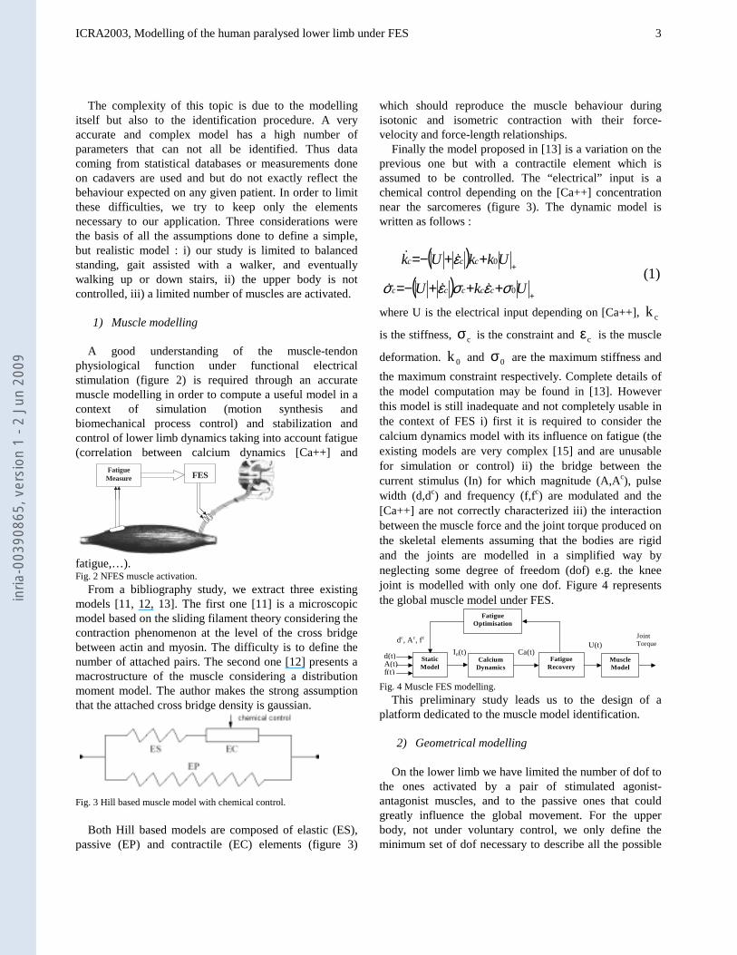
A good understanding of the muscle-tendon
physiological function under functional electrical stimulation (figure 2) is required through an accurate muscle modelling in order to compute a useful model in a context of simulation (motion synthesis and biomechanical process control) and stabilization and control of lower limb dynamics taking into account fatigue (correlation between calcium dynamics [Ca++] and
fatigue,…). Fig. 2 NFES muscle activation.
From a bibliography study, we extract three existing models [11, 12, 13]. The first one [11] is a microscopic model based on the sliding filament theory considering the contraction phenomenon at the level of the cross bridge between actin and myosin. The difficulty is to define the number of attached pairs. The second one [12] presents a macrostructure of the muscle considering a distribution moment model. The author makes the strong assumption that the attached cross bridge density is gaussian.
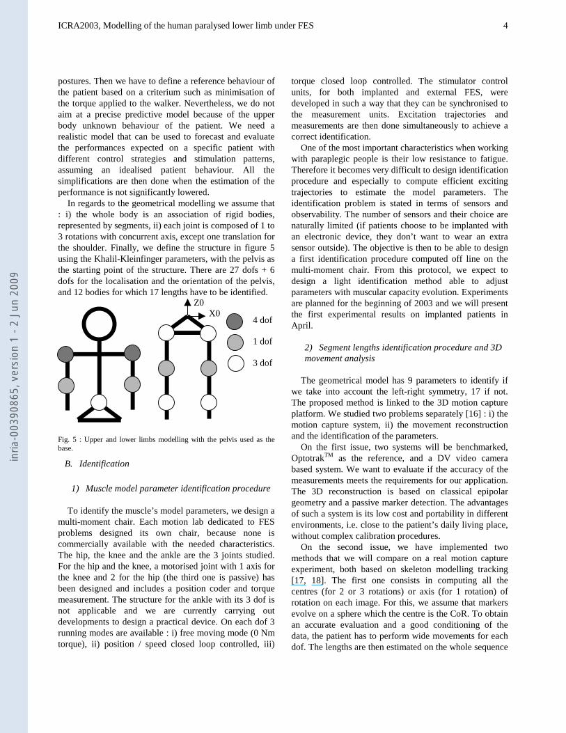
Fig. 3 Hill based muscle model with chemical control. Both Hill based models are composed of elastic (ES),
passive (EP) and contractile (EC) elements (figure 3)
which should reproduce the muscle behaviour during isotonic and isometric contraction with their force-velocity and force-length relationships.
Finally the model proposed in [13] is a variation on the previous one but with a contractile element which is assumed to be controlled. The “electrical” input is a chemical control depending on the [Ca++] concentration near the sarcomeres (figure 3). The dynamic model is written as follows :
where U is the electrical input depending on [Ca++], ck
is the stiffness, cσ is the constraint and cε is the muscle
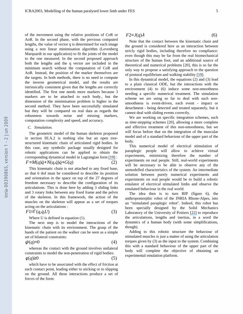
deformation. 0k and 0σ are the maximum stiffness and the maximum constraint respectively. Complete details of the model computation may be found in [13]. However this model is still inadequate and not completely usable in the context of FES i) first it is required to consider the calcium dynamics model with its influence on fatigue (the existing models are very complex [15] and are unusable for simulation or control) ii) the bridge between the current stimulus (In) for which magnitude (A,Ac), pulse width (d,dc) and frequency (f,fc) are modulated and the [Ca++] are not correctly characterized iii) the interaction between the muscle force and the joint torque produced on the skeletal elements assuming that the bodies are rigid and the joints are modelled in a simplified way by neglecting some degree of freedom (dof) e.g. the knee joint is modelled with only one dof. Figure 4 represents the global muscle model under FES.
Fig. 4 Muscle FES modelling. This preliminary study leads us to the design of a
platform dedicated to the muscle model identification. 2) Geometrical modelling
On the lower limb we have limited the number of dof to
the ones activated by a pair of stimulated agonist-antagonist muscles, and to the passive ones that could greatly influence the global movement. For the upper body, not under voluntary control, we only define the minimum set of dof necessary to describe all the possible
Fatigue Measure
FES
Static Model
d(t)A(t)f(t)
Calcium Dynamics
In(t)Fatigue
Recovery
Ca(t)U(t)
Muscle Model
Fatigue Optimisation
dc, Ac, fc Joint Torque
( )( )
)1(0
0
+
+
+++−=
++−=
UkU
UkkUk
ccccc
ccc
σεσεσ
ε
&&&
&&
inria
-003
9086
5, v
ersi
on 1
- 2
Jun
2009
ICRA2003, Modelling of the human paralysed lower limb under FES
4
postures. Then we have to define a reference behaviour of the patient based on a criterium such as minimisation of the torque applied to the walker. Nevertheless, we do not aim at a precise predictive model because of the upper body unknown behaviour of the patient. We need a realistic model that can be used to forecast and evaluate the performances expected on a specific patient with different control strategies and stimulation patterns, assuming an idealised patient behaviour. All the simplifications are then done when the estimation of the performance is not significantly lowered.
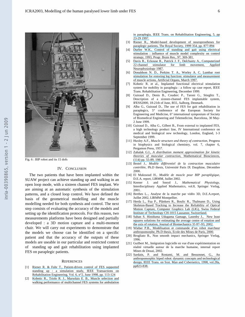
In regards to the geometrical modelling we assume that : i) the whole body is an association of rigid bodies, represented by segments, ii) each joint is composed of 1 to 3 rotations with concurrent axis, except one translation for the shoulder. Finally, we define the structure in figure 5 using the Khalil-Kleinfinger parameters, with the pelvis as the starting point of the structure. There are 27 dofs + 6 dofs for the localisation and the orientation of the pelvis, and 12 bodies for which 17 lengths have to be identified.
Fig. 5 : Upper and lower limbs modelling with the pelvis used as the base.
B. Identification 1) Muscle model parameter identification procedure
To identify the muscle’s model parameters, we design a
multi-moment chair. Each motion lab dedicated to FES problems designed its own chair, because none is commercially available with the needed characteristics. The hip, the knee and the ankle are the 3 joints studied. For the hip and the knee, a motorised joint with 1 axis for the knee and 2 for the hip (the third one is passive) has been designed and includes a position coder and torque measurement. The structure for the ankle with its 3 dof is not applicable and we are currently carrying out developments to design a practical device. On each dof 3 running modes are available : i) free moving mode (0 Nm torque), ii) position / speed closed loop controlled, iii)
torque closed loop controlled. The stimulator control units, for both implanted and external FES, were developed in such a way that they can be synchronised to the measurement units. Excitation trajectories and measurements are then done simultaneously to achieve a correct identification.
One of the most important characteristics when working with paraplegic people is their low resistance to fatigue. Therefore it becomes very difficult to design identification procedure and especially to compute efficient exciting trajectories to estimate the model parameters. The identification problem is stated in terms of sensors and observability. The number of sensors and their choice are naturally limited (if patients choose to be implanted with an electronic device, they don’t want to wear an extra sensor outside). The objective is then to be able to design a first identification procedure computed off line on the multi-moment chair. From this protocol, we expect to design a light identification method able to adjust parameters with muscular capacity evolution. Experiments are planned for the beginning of 2003 and we will present the first experimental results on implanted patients in April.
2) Segment lengths identification procedure and 3D movement analysis
The geometrical model has 9 parameters to identify if
we take into account the left-right symmetry, 17 if not. The proposed method is linked to the 3D motion capture platform. We studied two problems separately [16] : i) the motion capture system, ii) the movement reconstruction and the identification of the parameters.
On the first issue, two systems will be benchmarked, OptotrakTM as the reference, and a DV video camera based system. We want to evaluate if the accuracy of the measurements meets the requirements for our application. The 3D reconstruction is based on classical epipolar geometry and a passive marker detection. The advantages of such a system is its low cost and portability in different environments, i.e. close to the patient’s daily living place, without complex calibration procedures.
On the second issue, we have implemented two methods that we will compare on a real motion capture experiment, both based on skeleton modelling tracking [17, 18]. The first one consists in computing all the centres (for 2 or 3 rotations) or axis (for 1 rotation) of rotation on each image. For this, we assume that markers evolve on a sphere which the centre is the CoR. To obtain an accurate evaluation and a good conditioning of the data, the patient has to perform wide movements for each dof. The lengths are then estimated on the whole sequence
4 dof
1 dof
3 dof
Z0 X0
inria
-003
9086
5, v
ersi
on 1
- 2
Jun
2009
ICRA2003, Modelling of the human paralysed lower limb under FES
5
of the movement using the relative positions of CoR or AoR. In the second phase, with the previous computed lengths, the value of vector q is determined for each image using a non linear minimisation algorithm (Levenberg Marquardt in our application) to fit the joints of the model to the one measured. In the second proposed approach both the lengths and the q vector are included in the minimum search without the computation of CoR and AoR. Instead, the position of the marker themselves are the targets. In both methods, there is no need to compute the inverse geometrical model, and the results are intrinsically consistent given that the lengths are correctly identified. The first one needs more markers because 3 markers are to be attached to each body., but the dimension of the minimisation problem is higher in the second method. They have been successfully simulated but they will be compared on real data as regards the robustness towards noise and missing markers, computation complexity and speed, and accuracy.
C. Simulation. The geometric model of the human skeleton proposed
in section III.A.2 is nothing else but an open tree-structured kinematic chain of articulated rigid bodies. In this case, any symbolic package usually designed for robotic applications can be applied to obtain the corresponding dynamical model in Lagrangian form [19] :
)2()(),()( qGqqqNqqMF ++= &&&& This kinematic chain is not attached to any fixed base,
so that 6 dof must be considered to describe its position and orientation in the space on top of the 27 degrees of freedom necessary to describe the configuration of its articulations. This is done here by adding 3 sliding links and 3 rotary links between any fixed frame and the pelvis of the skeleton. In this framework, the action of the muscles on the skeleton will appear as a set of torques acting on the articulations :
)3(),,(1 UqqF &Γ= Where U is defined in equation (1). The next step is to model the interactions of the
kinematic chain with its environment. The grasp of the hands of the patient on the walker can be seen as a simple set of bilateral constraints:
)4(0)( =qψ whereas the contact with the ground involves unilateral
constraints to model the non-penetration of rigid bodies: )5(0)( ≥qφ
which have to be associated with the effect of friction at each contact point, leading either to sticking or to slipping on the ground. All these interactions produce a set of forces of the form:
)6()(2 λqJF = Note that the contact between the kinematic chain and
the ground is considered here as an interaction between stricly rigid bodies, including therefore no compliance: even though this may be far from the real biomechanical structure of the human foot, and an additional source of theoretical and numerical problems [20], this is so far the only way to propose a satisfying approach to the question of postural equilibrium and walking stability [19].
In this dynamical model, the equations (2) and (3) lead to a plain classical ODE, but the interactions with the environment (4) to (6) induce some non-smoothness needing a specific numerical treatment. The simulation scheme we are using so far to deal with such non-smoothness is event-driven, each event - impact or detachment - being detected and treated separately, but it cannot deal with sliding events correctly.
We are working on specific integration schemes, such as time-stepping schemes [20], allowing a more complete and effective treatment of this non-smoothness, but we will focus before that on the integration of the muscular model and of a standard behaviour of the upper part of the body.
This numerical model of electrical stimulation of paraplegic people will allow to achieve virtual experiments, minimizing therefore the number of experiments on real people. Still, real-world experiments will be necessary to be able to observe any of the unmodelled characteristics of the system. An intermediate solution between purely numerical experiments and experiments on real people would be to build a robotic emulator of electrical stimulated limbs and observe the emulated behaviour in the real world.
The idea then is to turn BIP (figure 6), the anthropomorphic robot of the INRIA Rhone-Alpes, into an “stimulated paraplegic robot''. Indeed, this robot has been specially designed by the Solid Mechanics Laboratory of the University of Poitiers [22] to reproduce the articulations, lengths and inertias, in a word the dynamics of a human body (with some simplifications, though).
Adding to this robotic structure the behaviour of stimulated muscles is just a matter of using the articulation torques given by (3) as the input to the system. Combining this with a standard behaviour of the upper part of the body will complete the objective of obtaining an experimental emulation platform.
inria
-003
9086
5, v
ersi
on 1
- 2
Jun
2009
ICRA2003, Modelling of the human paralysed lower limb under FES
6
Fig. 6 : BIP robot and its 15 dofs
IV. CONCLUSION The two patients that have been implanted within the
SUAW project can achieve standing up and walking in an open loop mode, with a sixteen channel FES implant. We are aiming at an automatic synthesis of the stimulation patterns, and a closed loop control. We have defined the basis of the geometrical modelling and the muscle modelling needed for both synthesis and control. The next step consists of evaluating the accuracy of the models and setting up the identification protocols. For this reason, two measurements platforms have been designed and partially developed : a 3D motion capture and a multi-moment chair. We will carry out experiments to demonstrate that the models we choose can be identified on a specific patient and that the accuracy of the outputs of these models are useable in our particular and restricted context of standing up and gait rehabilitation using implanted FES on paraplegic patients.
REFERENCES [1] Riener R. & Fuhr T., Patient-driven control of FES supported
standing up : a simulation study, IEEE Transactions on Rehabilitation Engineering, Vol. 6, n°2, June 1998, pp. 113-124
[2] Kobetic R., Triolo R. J., Marsolais E. B., Muscle selection and walking performance of multichannel FES systems for ambulation
in paraplegia, IEEE Trans. on Rehabilitation Engineering, 5, pp 23-29 1997.
[3] Riener R., Model-based development of neuroprostheses for paraplegic patients, The Royal Society, 1999 354, pp. 877-894
[4] Durfee W.K., Control of standing and gait using electrical stimulation : influence of muscle model complexity on control strategy, 1993, Progr. Brain Res., 97, 369-381.
[5] Davis R., Eckouse R., Patrick J. F., Delchanty A., Computerized 22-channel stimulator for limb movement, Applied Neurophysiology 1987.
[6] Donaldson N. D., Perkins T. A., Worley A. C. Lumbar root stimulation for restoring leg function: stimulator and measurement of muscle actions, Artificial Organs, March 1997.
[7] Kobetic R. et al., Implanted functional electrical stimulation system for mobility in paraplegia : a follow up case report, IEEE Trans. Rehabilitation Engineering, December 1999.
[8] Guiraud D., Denis B., Couderc P., Taroni G., Stieglitz T., Description of a sixteen-channel FES implantable system, IFESS2000, 18-21th of June, B55, Aalborg, Denmark.
[9] Alba G., Guiraud D., The use of FES for gait rehabilitation in paraplegics, 5° conference of the European Society for Engineering and Medicine, 6° international symposium of Society of Biomedical Engineering and Telemedicine, Barcelona, 30 May-2 June 1999.
[10] Guiraud D., Alba G., Gilbert B., From external to implanted FES, a high technology product line, IV International conference on medical and biological new technology, London, England, 1-3 September 1999.
[11] Huxley A.F., Muscle structure and theory of contraction, Progress in biophysics and biological chemistry, vol. 7, chapter 6, Pergamon Press, 1957.
[12] Zahalak G.I., A distribution moment approximation for kinetic theories of muscular contraction, Mathematical Biosciences, (114) pp. 55-89, 1981.
[13] Bestel J., Modèle différentiel de la contraction musculaire contrôlée, Ph.D thesis, Université Paris IX Dauphine, Décembre 2000.
[14] El Makssoud H., Modèle de muscle pour BIP paraplégique, D.E.A. report, LIRMM, Juillet 2002.
[15] Keener J. and Sneyd J., Mathematical Physiology, Interdisciplinary Applied Mathematics, vol.8, Springer Verlag, 2001.
[16] Brethes L.., Analyse de la marche par vidéo 3D, D.E.A.report, Juillet 2002, LIRMM Montpellier.
[17] Herda L., Fua P., Plänkers R., Boulic R., Thalmann D., Using Skeleton-Based Tracking to Increase the Reliability of Optical Motion Capture, Computer Graphics Lab (LIG), Swiss Federal Institute of Technology CH-1015 Lausanne, Switzerland.
[18] Sahan S. Hiniduma Udugama Gamage, Lasenby J., New least squares solutions for estimating the average centre of rotation and the axis of rotation, Journal of Biomechanics 35 87–93, 2002.
[19] Wieber P.B., Modélisation et commande d’un robot marcheur anthropomorphe, Ph.D thesis, Ecole des Mines de Paris, 2000.
[20] Brogliato B., Non smooth impact mechanics, Springer Verlag, 1996.
[21] Guilbert M., Intégration logicielle en vue d'une expérimentation en réalité virtuelle autour de la marche humaine, internal report Mines de Douai, 2002.
[22] Sardain, P. and Rostami, M. and Bessonnet, G., An anthropomorphic biped robot: dynamic concepts and technological design, IEEE Trans. on Syst. Man and Cybernetics, 1998, vol.28a, pp823-838.
inria
-003
9086
5, v
ersi
on 1
- 2
Jun
2009
Related Documents