http://ijd.sagepub.com/ Mechanics International Journal of Damage http://ijd.sagepub.com/content/22/3/356 The online version of this article can be found at: DOI: 10.1177/1056789512446820 2013 22: 356 originally published online 26 April 2012 International Journal of Damage Mechanics JL Curiel Sosa, S Phaneendra and JJ Munoz velocity impact Modelling of mixed damage on fibre reinforced composite laminates subjected to low Published by: http://www.sagepublications.com can be found at: International Journal of Damage Mechanics Additional services and information for http://ijd.sagepub.com/cgi/alerts Email Alerts: http://ijd.sagepub.com/subscriptions Subscriptions: http://www.sagepub.com/journalsReprints.nav Reprints: http://www.sagepub.com/journalsPermissions.nav Permissions: http://ijd.sagepub.com/content/22/3/356.refs.html Citations: What is This? - Apr 26, 2012 OnlineFirst Version of Record - Mar 14, 2013 Version of Record >> at University of Sheffield on April 1, 2013 ijd.sagepub.com Downloaded from

Welcome message from author
This document is posted to help you gain knowledge. Please leave a comment to let me know what you think about it! Share it to your friends and learn new things together.
Transcript
http://ijd.sagepub.com/Mechanics
International Journal of Damage
http://ijd.sagepub.com/content/22/3/356The online version of this article can be found at:
DOI: 10.1177/1056789512446820
2013 22: 356 originally published online 26 April 2012International Journal of Damage MechanicsJL Curiel Sosa, S Phaneendra and JJ Munoz
velocity impactModelling of mixed damage on fibre reinforced composite laminates subjected to low
Published by:
http://www.sagepublications.com
can be found at:International Journal of Damage MechanicsAdditional services and information for
http://ijd.sagepub.com/cgi/alertsEmail Alerts:
http://ijd.sagepub.com/subscriptionsSubscriptions:
http://www.sagepub.com/journalsReprints.navReprints:
http://www.sagepub.com/journalsPermissions.navPermissions:
http://ijd.sagepub.com/content/22/3/356.refs.htmlCitations:
What is This?
- Apr 26, 2012OnlineFirst Version of Record
- Mar 14, 2013Version of Record >>
at University of Sheffield on April 1, 2013ijd.sagepub.comDownloaded from

Article
Modelling of mixed damage onfibre reinforced compositelaminates subjected to lowvelocity impact
JL Curiel Sosa1, S Phaneendra2 and JJ Munoz2
Abstract
This article presents a numerical technique for the computation of damage in fibre-reinforced laminated
composites which is embedded into an explicit finite element method. The technique is composed of two
main components. First, a novel characterisation of the directions in which the various modes of damage
propagate, which produces an effective damage localisation. This is conducted taking into consideration
the strain-rate dependence. Second, a new mapping between the strain and stress spaces for the com-
putation of the damage surfaces whereby time-stepping convergence is enhanced. Additionally, new
damage initiation criteria in terms of strain damage surfaces are presented. Details of the in-house code
developed are presented as well as the programming features. The capabilities of the technique are shown
by means of tests on single fibre-reinforced element and low velocity impact on the laminate. It is shown that
delamination is located in the expected regions by gradual progression of internal damage variables.
Keywords
damage, composite, finite element method, impact, laminate, failure
Introduction
From a computational point of view, numerical techniques based on a progressive evolution ofdamage in composite materials, e.g. Maimi et al. (2007a, 2007b), Tan (1991), Harris et al. (1995),Raimondo et al. (2012), Donadon et al. (2008), Liu and Zheng (2010), Singh and Talreja (2008) andSingh and Talreja (2010), are more stable than stress failure criteria, e.g. Hashin (1980), Tsai and Wu(1971), Puck and Schurmann (1998), Chang and Chang (1987), Hinton and Soden (1998) and Sodenet al. (1998a), with respect to the erosion – deletion – of finite elements as these progressivelydegrade, matching stiffness deterioration and mitigating in that manner the undesirable instabilitiesof the numerical method. Advantages and disadvantages of these two general trends mentioned are
International Journal of Damage
Mechanics
22(3) 356–374
! The Author(s) 2012
Reprints and permissions:
sagepub.co.uk/journalsPermissions.nav
DOI: 10.1177/1056789512446820
ijd.sagepub.com
1Mechanical Engineering Subject Group, Department of Engineering and Mathematics, Sheffield Hallam University, UK2LaCaN, Department of Applied Mathematics III, School of Civil Engineering, Polytechnic University of Catalonia, Spain
Corresponding author:
JL Curiel Sosa, Mechanical Engineering Subject Group, Department of Engineering and Mathematics, Sheffield Hallam University,
Howard Street, Sheffield, S11WB, UK.
Email: [email protected]
at University of Sheffield on April 1, 2013ijd.sagepub.comDownloaded from

still recurring subjects of debate (Daniel, 2007). Cohesive elements have become very popular asdiscontinuities may efficiently be simulated, e.g. splitting due to delamination (Camanho andMathews, 1999; Camanho et al., 2003; Tvergaard, 2004; Iannucci and Willows, 2006). An up-to-date review can be found in Wisnom (2010). The proposed technique admits linkage to cohesiveelements, although this is not attempted at this time.
The proposed technique is framed on the thermodynamics of irreversible process following Chaboche(1992). Other interesting thermodynamical approaches for damage mechanics of composites are alsofound in literature, e.g. Simo and Ju (1987), Turon et al. (2006), Allen et al. (1987), amongst others. Froma purely damage mechanics point of view, the main features of the proposed technique are the compu-tation of paths of damages which provide an effective localisation of the different damage modes and,second, the computation of damage on the strain space through the generation of amapping between thestrain and stress spaces where the so-called normalised energy release rates are readily computed. Thus,the undamaged domain is defined on the strain space bounded for a set of quadratic damage surfaces.The approach is based on computing the damage at quadrature points, i.e. gauss points, within eachfiniteelement, forming the mesh of the composite which is performed in the strain space. Moreover, fractureenergy – modes I and II – can be added to the model and mapped onto to the strain space following ananalogous strategy. This last point permits to treat all the variables associated to failure on the compositein a progressive manner which provides higher stability and convergence in the explicit finite elementmethod (XPFEM) procedure, as the removal of a finite element often causes oscillations when usingXPFEM, creating instability, and, eventually, divergence (Camanho et al., 2001).
This article is outlined as follows. First, the thermodynamical background, in which the techniqueis framed, is briefly presented. Second, definition of the measurements of stress utilised are provided.Third, damage components of the technique are described. Fourth, the integration within XPFEM ispresented in some detail. Finally, numerical results and discussion are provided. Additionally, anappendix containing relevant tensors is included.
Thermodynamics of damage in dissipative materials
The case of irreversible process in dissipative materials considered follows the framework byChaboche (1992). A brief summary is highlighted in this section to frame the background of thestudy. The definition of the damage state is described by a set of internal damage variables (Germainet al., 1983; Talreja, 1987; Lundmark and Varna, 2005; Talreja, 2006; Desmorat et al., 2010; Yanget al., 2010). The thermodynamic potential is represented by the specific free energy, �. Since non-metallic composites are approached, plasticity and hardening terms may be ignored. In this case, thefree energy � takes the following expression
� :¼1
2e : C : e ð1Þ
Here and henceforth, bold symbols and bold characters denote tensor and vector variables. Thesymbol e denotes the second-order strain tensor and ‘:’ the inner product. The constitutive law isrepresented by the damaged secant stiffness, C, which is, in general, a fourth-order tensor (Simo andJu, 1987). This tensor is a function of the internal damage variables �ij, equation (2). These variablesare integrated in the tensor g.
CðgÞ ¼ 2@�
@ ðe� eÞr ¼
@�
@ e¼ C : e ð2Þ
Sosa et al. 357
at University of Sheffield on April 1, 2013ijd.sagepub.comDownloaded from

where � is the tensor product. Chaboche (1992) defines the energy release rates as the derivative ofthis potential respect to the internal damage variables,
Yðe , gÞ :¼ �@�
@ g¼ �
1
2e :@C
@ g: e ð3Þ
where Y denotes a second-order tensor containing the thermodynamic forces Yij. The dissipativepotential is related to the irreversibility of the process which is caused by distinct damage modes inthe case of composites. The dissipative potential is a function of the thermodynamic forces Yij andthe damage state itself. Following Chaboche (1992), the dissipative potential is replaced by damagecriteria. Equation (4) defines the elastic undamaged domain on the strain space.
g :¼ gðe� e , gÞ � 0 ð4Þ
In the proposed technique (‘Damage computation’), a new criteria is proposed as a substitute forthe dissipative potential which takes into account the so-called normalised energy release rates asconstituents.
Measurement of stress
Although the stress–strain relationship, in general, for composites with potential anisotropic damageimplies the formulation in terms of a fourth-order tensor (Simo and Ju, 1987), the attempt, here, isrestricted to orthotropic fibre-reinforced laminae and, therefore, the constitutive tensor can be rep-resented by a second-order tensor as described below. The stress is measured using the definition ofeffective stress r by Chaboche (1981), that is equation (5). In Figure 1, the different measurements ofstress, effective and nominal, are schematically depicted. Furthermore, the principle of strain equiva-lence (Lemaitre and Chaboche, 1990) is applied on the constitutive law. Following Simo and Ju(1987), the damage matrix D is formed by the internal damage variables �ij, equation (6), which arerelated to stiffness degradation of the composite in the corresponding directions.
rn ¼ DðgnÞ � rn ð5Þ
⟩
σ
εε
σ
A
D
⟩ ] ]
A
Figure 1. Schematic representation of the principle of strain equivalence (Lemaitre and Chaboche, 1990) relating both
measures of stress used, effective � and nominal �.
The red line indicates the final deformed configuration. This principle asserts that the effective stress acting over A,
total area minus area of the microcracks or defects, produces the same strain as that of the nominal stress acting over
the total area A.
358 International Journal of Damage Mechanics 22(3)
at University of Sheffield on April 1, 2013ijd.sagepub.comDownloaded from

Material axis {1, 2, 3} are used for the definition of tensors and vectors at plies – unidirectional(UD) layers. They are local in the ply and are rotated to a global axis {x, y, z} for the final couplingof the global system of momentum equations. The transformation of tensors from an off-axis con-figuration can be consulted in any standard reference for mechanics of laminar composites such asStaab (1999). Material axis at the ply level are defined following the conventional standards:
. 1-direction: longitudinal to fibres,
. 2-direction: in-plane perpendicular to fibres, and
. 3-direction: out-of-plane perpendicular to fibres.
The stress is introduced as a contracted vector, rn ¼ �11 , �22 , �33 , �12 , �23 , �31½ �T
n, equation (5), andthe diagonal of the damage tensor contains the damage variables �ij linked to the deterioration of thestiffness components, as shown in equation (6). g denotes a vector – from a contracted tensor –containing the internal damage variables, gn ¼ �11 , �22 , �33 , �12 , �23 , �31½ �
T
n, which define the damagestate. Henceforth, subscript n denotes that the computation of the variable or tensor affected by itrefers to the time step tn of the proposed time-marching technique.
DijðgnÞ ¼ �ij=ð1� �ijjnÞ ð6Þ
where �ij is the Kronecker delta.a The stress–strain relationship is provided in equation (7), whereC0 is a second-order constitutive tensor that contains the initial values of stiffness components,unaffected by any damage. Finally, the stress–strain relationship may be written through aconstitutive matrix that integrates the deterioration of its components due to the damage modes,equation (7).
rn ¼ D�1ðgnÞ � C0 � en ¼ Cn � en ð7Þ
Damage computation
Mapping and characterisation of undamaged domain
The damage surfaces bound the undamaged domain composed for as many as the numbers ofdamage modes x modelled. In other words, every damage mode is linked to a stress damage surfacethat in turn is mapped onto the strain space as explained next. Normalised energy release rates areprovided in equation (8). These strain damage surfaces are obtained by the mapping in equation(11), from normalised energy release rates on the stress space
�Yijðrn , gnÞ :¼
�2ii2Eið1��2iiÞX
ðtÞii
jn if i ¼ j and �ii� 0
�2ii2Eið1��2iiÞX
ðcÞii
jn if i ¼ j and �ii5 0
�2ij2Sijð1��2ijÞXij
jn if i 6¼j
8>>>>><>>>>>:
ð8Þ
aThe Kronecker delta, �ij, is 1 if i¼ j and, 0 otherwise.
Sosa et al. 359
at University of Sheffield on April 1, 2013ijd.sagepub.comDownloaded from

where Ei denotes the Young’s modulus in direction i, Sij the elastic shear modulus associated todirections i and j, XðtÞ
iithe direct tensile strength of the laminate in direction i and Xij the shear
strength related to the corresponding directions. The stress damage surfaces are
f �ðrn , gnÞ :¼ f �ð �Yijðrn , gnÞÞ � ¼ 1 , 2 , . . . ,m ð9Þ
For convenience, equation (9) is rearranged as follows in equation (10).
f � ðrn , gnÞ :¼ rT
n � F�ðgnÞ � rn � 1 � ¼ 1 , 2 , . . . ,m ð10Þ
where Fx denotes the tensor associated to the damage mode x and m the total number of damagemodes modelled, see Appendix. The mapping in equation (11) is obtained by previous computationof these damage surfaces on the stress space. Thus, these stress damage surfaces are built as functionof the so-called normalised energy release rates in equation (8) due to the propagation of damagevariables. The stress damage surfaces fx shrink with the progression and development of any damagemode affecting them. The initial spherical damage quadratic form turns into an ellipsoid (Figure (2))due to the progression of damage and the volume is re-shaped and, therefore, the undamageddomain on the strain space is consequently reduced. Once fx is calculated, the corresponding gx
damage surface on the strain space is computed at each quadrature point on the finite element undercalculation according to
G�ðgnÞ ¼ CT
n � F�ðgnÞ � Cn � ¼ 1 , 2 , . . . ,m ð11Þ
g�ðen , gnÞ :¼ eTn �G�ðgnÞ � en � 1 � ¼ 1 , 2 , . . . ,m ð12Þ
−50
0
50
−50
0
50−20
0
20
σ22σ12
σ 23
Figure 2. Stress damage surface due to fibre rupture (x1) on a tensile test. The initial spherical damage quadratic
form turns into an ellipsoid due to the progression of damage.
360 International Journal of Damage Mechanics 22(3)
at University of Sheffield on April 1, 2013ijd.sagepub.comDownloaded from
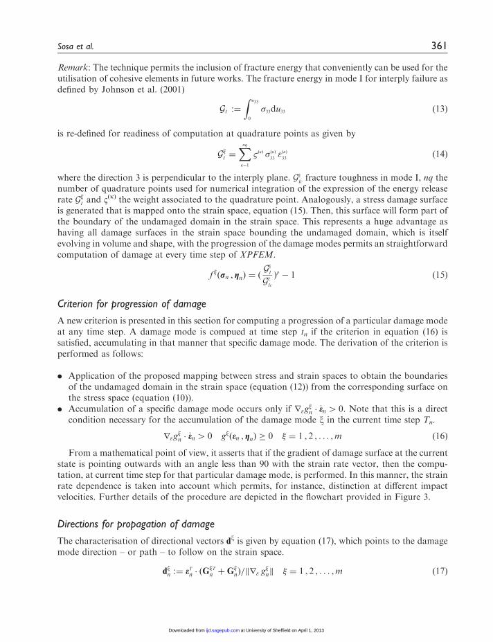
Remark: The technique permits the inclusion of fracture energy that conveniently can be used for theutilisation of cohesive elements in future works. The fracture energy in mode I for interply failure asdefined by Johnson et al. (2001)
GI :¼
Zu33
0
�33du33 ð13Þ
is re-defined for readiness of computation at quadrature points as given by
G�I¼Xnq�¼1
&ð�Þ �ð�Þ33"ð�Þ33
ð14Þ
where the direction 3 is perpendicular to the interply plane. G�Icfracture toughness in mode I, nq the
number of quadrature points used for numerical integration of the expression of the energy releaserate G�
Iand �(k) the weight associated to the quadrature point. Analogously, a stress damage surface
is generated that is mapped onto the strain space, equation (15). Then, this surface will form part ofthe boundary of the undamaged domain in the strain space. This represents a huge advantage ashaving all damage surfaces in the strain space bounding the undamaged domain, which is itselfevolving in volume and shape, with the progression of the damage modes permits an straightforwardcomputation of damage at every time step of XPFEM.
f �ðrn , gnÞ ¼ ðG�
I
G�
Ic
Þp� 1 ð15Þ
Criterion for progression of damage
A new criterion is presented in this section for computing a progression of a particular damage modeat any time step. A damage mode is compued at time step tn if the criterion in equation (16) issatisfied, accumulating in that manner that specific damage mode. The derivation of the criterion isperformed as follows:
. Application of the proposed mapping between stress and strain spaces to obtain the boundariesof the undamaged domain in the strain space (equation (12)) from the corresponding surface onthe stress space (equation (10)).
. Accumulation of a specific damage mode occurs only if r"g�n � _en 4 0. Note that this is a direct
condition necessary for the accumulation of the damage mode x in the current time step Tn.
r"g�n � _en 4 0 g�ðen , gnÞ � 0 � ¼ 1 , 2 , . . . ,m ð16Þ
From a mathematical point of view, it asserts that if the gradient of damage surface at the currentstate is pointing outwards with an angle less than 90 with the strain rate vector, then the compu-tation, at current time step for that particular damage mode, is performed. In this manner, the strainrate dependence is taken into account which permits, for instance, distinction at different impactvelocities. Further details of the procedure are depicted in the flowchart provided in Figure 3.
Directions for propagation of damage
The characterisation of directional vectors dx is given by equation (17), which points to the damagemode direction – or path – to follow on the strain space.
d�n :¼ eTn � ðG�Tn þG�
nÞ=kr" g�nk � ¼ 1 , 2 , . . . ,m ð17Þ
Sosa et al. 361
at University of Sheffield on April 1, 2013ijd.sagepub.comDownloaded from

Damage Stiffness Tensor
Loop over quadrature points ,qp
Loop over damage modes
Normalised Energy Release Rates , Eq.(8)
Stress Damage Tensor, Eq.(10)
Stress Damage Surfaces, Eq.(9)
Mapping onto Strain Space, Eq.(11)
Damage Strain Surface, Eq.(12)
Yes
Yes
Yes
No
No
No
Update damage rate, Eq.(19)
Increment of damage mode, Eq.(18)
Damage direction, Eq.(17)
NextMode
Nextq.p.?
Criteria,Eq.(16)?
Figure 3. Detailed flowchart of the calculation of damage progression associated to the different modes computed
at the quadrature point level.
This algorithm is nested within the loop over finite elements and embedded into the time-stepping scheme as
described in ‘Explicit time-stepping scheme’. Note that in XPFEM, there is a spatial discretisation by finite elements
and a time discretisation by finite differences (Belytschko et al., 2001).
Progression of damage
Once the criterion in equation (16) is accomplished, the progression of the damage mode x con-cerned is conducted by the description given by
�n :¼ ðr"g�n � _enÞ
1=p � ¼ 1 , 2 , . . . ,m ð18Þ
362 International Journal of Damage Mechanics 22(3)
at University of Sheffield on April 1, 2013ijd.sagepub.comDownloaded from
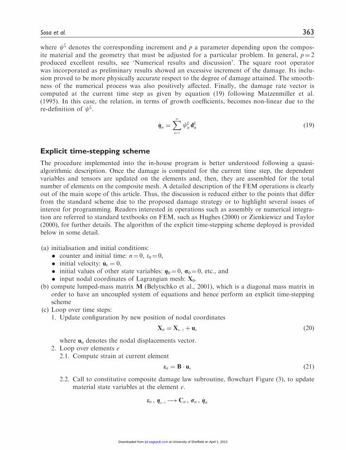
where x denotes the corresponding increment and p a parameter depending upon the compos-ite material and the geometry that must be adjusted for a particular problem. In general, p¼ 2produced excellent results, see ‘Numerical results and discussion’. The square root operatorwas incorporated as preliminary results showed an excessive increment of the damage. Its inclu-sion proved to be more physically accurate respect to the degree of damage attained. The smooth-ness of the numerical process was also positively affected. Finally, the damage rate vector iscomputed at the current time step as given by equation (19) following Matzenmiller et al.(1995). In this case, the relation, in terms of growth coefficients, becomes non-linear due to there-definition of x.
_gn ¼Xm
�¼1
�n d�n ð19Þ
Explicit time-stepping scheme
The procedure implemented into the in-house program is better understood following a quasi-algorithmic description. Once the damage is computed for the current time step, the dependentvariables and tensors are updated on the elements and, then, they are assembled for the totalnumber of elements on the composite mesh. A detailed description of the FEM operations is clearlyout of the main scope of this article. Thus, the discussion is reduced either to the points that differfrom the standard scheme due to the proposed damage strategy or to highlight several issues ofinterest for programming. Readers interested in operations such as assembly or numerical integra-tion are referred to standard textbooks on FEM, such as Hughes (2000) or Zienkiewicz and Taylor(2000), for further details. The algorithm of the explicit time-stepping scheme deployed is providedbelow in some detail.
(a) initialisation and initial conditions:. counter and initial time: n¼ 0, t0¼ 0,. initial velocity: _u0 ¼ 0;. initial values of other state variables: g0¼ 0, p0¼ 0, etc., and. input nodal coordinates of Lagrangian mesh: X0.
(b) compute lumped-mass matrix M (Belytschko et al., 2001), which is a diagonal mass matrix inorder to have an uncoupled system of equations and hence perform an explicit time-steppingscheme
(c) Loop over time steps:1. Update configuration by new position of nodal coordinates
Xn ¼ Xn�1 þ un ð20Þ
where un denotes the nodal displacements vector.2. Loop over elements e
2.1. Compute strain at current element
en ¼ B � un ð21Þ
2.2. Call to constitutive composite damage law subroutine, flowchart Figure (3), to updatematerial state variables at the element e.
en , gn�1�!Cn , rn , _gn
Sosa et al. 363
at University of Sheffield on April 1, 2013ijd.sagepub.comDownloaded from
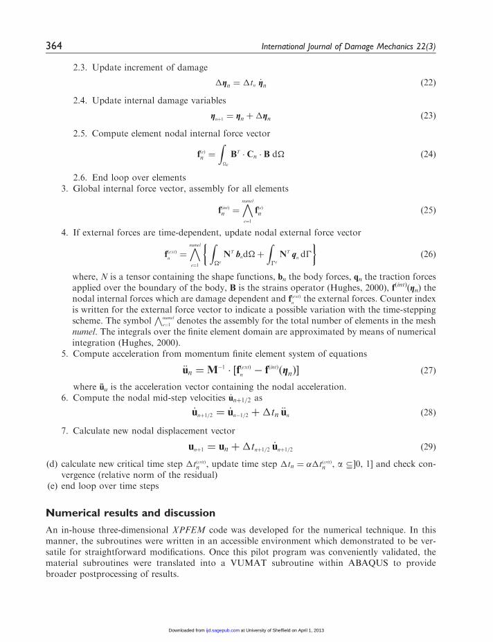
2.3. Update increment of damage
�gn ¼ �tn _gn ð22Þ
2.4. Update internal damage variables
gnþ1 ¼ gn þ�gn ð23Þ
2.5. Compute element nodal internal force vector
fðeÞn ¼
Z�e
BT � Cn � B d� ð24Þ
2.6. End loop over elements3. Global internal force vector, assembly for all elements
fðintÞn ¼
numel
e¼1
fðeÞn ð25Þ
4. If external forces are time-dependent, update nodal external force vector
fðextÞn¼
numel
e¼1
� Z�e
NT bnd�þ
Z�e
NT qn d�
�ð26Þ
where, N is a tensor containing the shape functions, bn the body forces, qn the traction forcesapplied over the boundary of the body, B is the strains operator (Hughes, 2000), f(int)(gn) thenodal internal forces which are damage dependent and fðextÞ
nthe external forces. Counter index
is written for the external force vector to indicate a possible variation with the time-steppingscheme. The symbol
Vnumel
e¼1denotes the assembly for the total number of elements in the mesh
numel. The integrals over the finite element domain are approximated by means of numericalintegration (Hughes, 2000).
5. Compute acceleration from momentum finite element system of equations
€un ¼M�1 � ½fðextÞn� fðintÞðgnÞ� ð27Þ
where uu is the acceleration vector containing the nodal acceleration.6. Compute the nodal mid-step velocities _unþ1=2 as
_unþ1=2 ¼ _un�1=2 þ�tn €un ð28Þ
7. Calculate new nodal displacement vector
unþ1 ¼ un þ�tnþ1=2 _unþ1=2 ð29Þ
(d) calculate new critical time step �tðcritÞn , update time step �tn ¼ ��tðcritÞn , a 7]0, 1] and check con-vergence (relative norm of the residual)
(e) end loop over time steps
Numerical results and discussion
An in-house three-dimensional XPFEM code was developed for the numerical technique. In thismanner, the subroutines were written in an accessible environment which demonstrated to be ver-satile for straightforward modifications. Once this pilot program was conveniently validated, thematerial subroutines were translated into a VUMAT subroutine within ABAQUS to providebroader postprocessing of results.
364 International Journal of Damage Mechanics 22(3)
at University of Sheffield on April 1, 2013ijd.sagepub.comDownloaded from
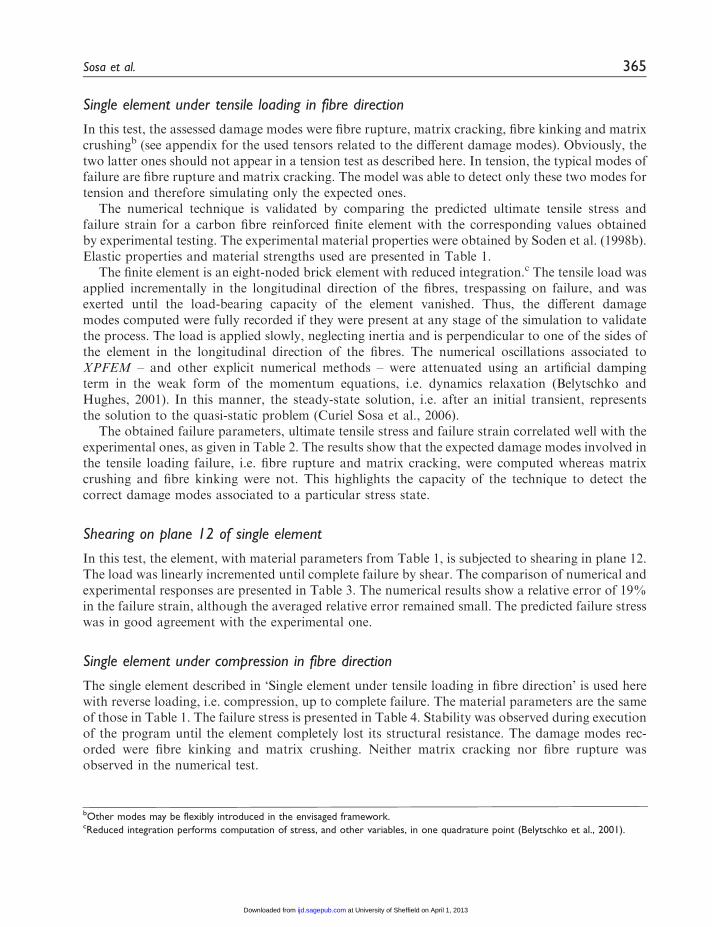
Single element under tensile loading in fibre direction
In this test, the assessed damage modes were fibre rupture, matrix cracking, fibre kinking and matrixcrushingb (see appendix for the used tensors related to the different damage modes). Obviously, thetwo latter ones should not appear in a tension test as described here. In tension, the typical modes offailure are fibre rupture and matrix cracking. The model was able to detect only these two modes fortension and therefore simulating only the expected ones.
The numerical technique is validated by comparing the predicted ultimate tensile stress andfailure strain for a carbon fibre reinforced finite element with the corresponding values obtainedby experimental testing. The experimental material properties were obtained by Soden et al. (1998b).Elastic properties and material strengths used are presented in Table 1.
The finite element is an eight-noded brick element with reduced integration.c The tensile load wasapplied incrementally in the longitudinal direction of the fibres, trespassing on failure, and wasexerted until the load-bearing capacity of the element vanished. Thus, the different damagemodes computed were fully recorded if they were present at any stage of the simulation to validatethe process. The load is applied slowly, neglecting inertia and is perpendicular to one of the sides ofthe element in the longitudinal direction of the fibres. The numerical oscillations associated toXPFEM – and other explicit numerical methods – were attenuated using an artificial dampingterm in the weak form of the momentum equations, i.e. dynamics relaxation (Belytschko andHughes, 2001). In this manner, the steady-state solution, i.e. after an initial transient, representsthe solution to the quasi-static problem (Curiel Sosa et al., 2006).
The obtained failure parameters, ultimate tensile stress and failure strain correlated well with theexperimental ones, as given in Table 2. The results show that the expected damage modes involved inthe tensile loading failure, i.e. fibre rupture and matrix cracking, were computed whereas matrixcrushing and fibre kinking were not. This highlights the capacity of the technique to detect thecorrect damage modes associated to a particular stress state.
Shearing on plane 12 of single element
In this test, the element, with material parameters from Table 1, is subjected to shearing in plane 12.The load was linearly incremented until complete failure by shear. The comparison of numerical andexperimental responses are presented in Table 3. The numerical results show a relative error of 19%in the failure strain, although the averaged relative error remained small. The predicted failure stresswas in good agreement with the experimental one.
Single element under compression in fibre direction
The single element described in ‘Single element under tensile loading in fibre direction’ is used herewith reverse loading, i.e. compression, up to complete failure. The material parameters are the sameof those in Table 1. The failure stress is presented in Table 4. Stability was observed during executionof the program until the element completely lost its structural resistance. The damage modes rec-orded were fibre kinking and matrix crushing. Neither matrix cracking nor fibre rupture wasobserved in the numerical test.
bOther modes may be flexibly introduced in the envisaged framework.cReduced integration performs computation of stress, and other variables, in one quadrature point (Belytschko et al., 2001).
Sosa et al. 365
at University of Sheffield on April 1, 2013ijd.sagepub.comDownloaded from

Low-velocity impact on laminate
The proposed technique is used to simulate maps of damage in a cross-ply laminate when impactedby a projectile at low velocity. Hou et al. (2000) performed this test. Their experimental workinvolved the use of a titanium projectile of 260 g, 9.55mm in diameter and ended with a spherical
Table 1. Material properties of the carbon reinforced epoxy lamina (Soden et al., 1998b) used in single-element
tests.
Lamina properties (single-element tests)
Young’s modulus, E1 (GPa) 126
Young’s modulus, E2, E3 (GPa) 11
Shear modulus, S12, S31 (GPa) 6.6
Shear modulus, S23 (GPa) 3.93
Poisson ratios, �12, �31 0.28
Poisson ratio, �23 0.4
Tensile strength in fibre direction, XðtÞ11
(MPa) 1950
Compressive strength in fibre direction, XðcÞ11
(MPa) �1480
Perpendicular to fibre tensile strength, XðtÞ22
, XðtÞ33
(MPa) 48
Perpendicular to fibre compressive strength, XðcÞ22
, XðcÞ33
(MPa) �200
Shear strength, X12, X31 (MPa) 79
Shear strength, X23 (MPa) 17.14
Superscripts (t) and (c) denote tension and compression respectively.
Table 4. Results for single element under compression in fibre direction.
Experimental Numerical Relative error (%)
�11,f (MPa) �1480 �1558 5.2
Table 2. Values of ultimate stress, �11,UTS, and failure strain, e11,f from longitudinal (fibre direction) tensile loading
tests on a lamina with mechanical properties given in Table 1.
Experimentala Numerical Relative error (%)
�11,UTS (MPa) 1950 1966.7 0.82
e11,f (%) 0.0138 0.0157 14.5
aExperimental results were obtained by Soden et al. (1998b)
Table 3. Results from shearing on plane 12 of single element.
Experimental Numerical Relative error (%)
�12,f (MPa) 79 84.3 6.7
e12,f (%) 0.021 0.025 19.07
366 International Journal of Damage Mechanics 22(3)
at University of Sheffield on April 1, 2013ijd.sagepub.comDownloaded from
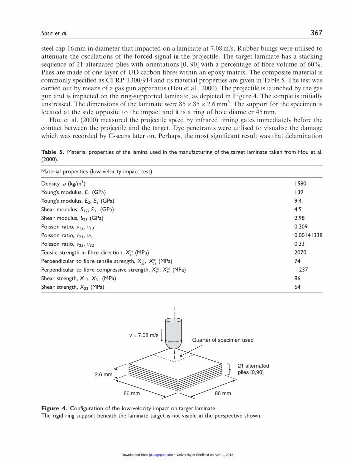
steel cap 16mm in diameter that impacted on a laminate at 7.08m/s. Rubber bungs were utilised toattenuate the oscillations of the forced signal in the projectile. The target laminate has a stackingsequence of 21 alternated plies with orientations [0, 90] with a percentage of fibre volume of 60%.Plies are made of one layer of UD carbon fibres within an epoxy matrix. The composite material iscommonly specified as CFRP T300/914 and its material properties are given in Table 5. The test wascarried out by means of a gas gun apparatus (Hou et al., 2000). The projectile is launched by the gasgun and is impacted on the ring-supported laminate, as depicted in Figure 4. The sample is initiallyunstressed. The dimensions of the laminate were 85� 85� 2.6mm3. The support for the specimen islocated at the side opposite to the impact and it is a ring of hole diameter 45mm.
Hou et al. (2000) measured the projectile speed by infrared timing gates immediately before thecontact between the projectile and the target. Dye penetrants were utilised to visualise the damagewhich was recorded by C-scans later on. Perhaps, the most significant result was that delamination
Quarter of specimen usedv = 7.08 m/s
2.6 mm
21 alternatedplies [0,90]
86 mm86 mm
Figure 4. Configuration of the low-velocity impact on target laminate.
The rigid ring support beneath the laminate target is not visible in the perspective shown.
Table 5. Material properties of the lamina used in the manufacturing of the target laminate taken from Hou et al.
(2000).
Material properties (low-velocity impact test)
Density, (kg/m3) 1580
Young’s modulus, E1 (GPa) 139
Young’s modulus, E2, E3 (GPa) 9.4
Shear modulus, S12, S31 (GPa) 4.5
Shear modulus, S23 (GPa) 2.98
Poisson ratio, �12, �13 0.209
Poisson ratio, �21, �31 0.00141338
Poisson ratio, �23, �32 0.33
Tensile strength in fibre direction, XðtÞ11
(MPa) 2070
Perpendicular to fibre tensile strength, XðtÞ22
, XðtÞ33
(MPa) 74
Perpendicular to fibre compressive strength, XðcÞ22
, XðcÞ33
(MPa) �237
Shear strength, X12, X31 (MPa) 86
Shear strength, X23 (MPa) 64
Sosa et al. 367
at University of Sheffield on April 1, 2013ijd.sagepub.comDownloaded from

was not observed in the through-thickness compressive region beneath the projectile impact zone,i.e. the centre of the target laminate (Figure 5). Our proposed technique replicates this effect, seeFigure 6. This effect is caused because of the symmetry of the configuration.
The target laminate was modelled using one finite element per ply in the transversal direction,making 21 elements through the thickness of the laminate in total. The finite element used is an eightnoded hexahedra element with reduced integration. For this test, the numerical technique wasimplemented in FORTRAN language into a VUMAT subroutine for ABAQUS software. Thenumber of state variables representing damage was set to six and the number of damage modesmodelled was six. These were fibre rupture, fibre kinking, matrix cracking (in both normal-to-fibredirections) and matrix crushing (also in both normal-to-fibre directions). The main expressions oftensors and other variables can be found in ‘Appendix’. Thanks to the symmetry and, in order tosave computational cost, the configuration was reduced to one quarter of the original geometry forall components, i.e. projectile, specimen and rigid support.
Although the proposed technique is mesh-dependent, regularisation, e.g. Petrinic et al. (2006), isnot attempted here as the interest is to replicate experimental response for matrix crushing anddelamination mainly with the same mesh as Hou et al. (2000). However, it is encouraged to developnon-local strategies within the proposed technique for simulation of damage independent of the sizeof the finite elements in future works. Because of the utilisation of reduced integration, hourglassingcontrold was used to avoid unrealistic distortion of elements. The contact condition was set forsurface–surface. The shear stress fields are depicted in Figures 7 and Figure 8. Shear stresses play amajor role in the initiation and development of delamination in these type of problems. Figure 9shows the final matrix crushing once the projectile has bounced back. The crushing damage is
Figure 5. Approximated localisation of delamination from experimental results by Hou et al. (2000).
The figure represents a through-thickness view of a quarter of the target laminate. Middle vertical line indicates the
corner.
Figure 6. View through section-cut interply damage (delamination) on a quarter laminate.
Localisation of delamination correlates well with the experimental map of damage provided by Hou et al. (2000). In
that work, a delamination-free region was recorded just beneath the projectile, in through-thickness impact zone. The
simulation was able to model that delamination-free zone as can be observed in this figure.
dprovided by ABAQUS software.
368 International Journal of Damage Mechanics 22(3)
at University of Sheffield on April 1, 2013ijd.sagepub.comDownloaded from

Figure 7. Contour plot of shear stress �23. �ðmaxÞ
23¼ 36:17 MPa (red contour); �ðminÞ
23¼ �15:48 MPa (blue
contour).
Figure 8. Contour plot of shear stress �13. �ðmaxÞ
13¼ 36:15 MPa (red contour); �ðminÞ
13¼ �14:76 MPa (blue
contour).
Figure 9. Detail of matrix crushing map of damage in the through-thickness impact zone, under the impactor.
The crushed region was observed in the expected location.
Sosa et al. 369
at University of Sheffield on April 1, 2013ijd.sagepub.comDownloaded from
located in the contact zone beneath the impactor which correlates with the results by Hou et al.(2000). Figure 6 represents the delamination region, with grades, matching the experimental map,Figure 5, of damage obtained from the gas gun in a significant region and leaving efficiently withoutdelamination of the central part.
Conclusion
The development of a new technique for simulation of damage modes in fibre reinforced compositelaminates was presented in this article. The explicit time-stepping technique embedded within theFEM was shown in detail as well as novel features, which included:
(a) formulation of damage directions whereby propagation of the different damage modes wascomputed,
(b) increment of damage, i.e. growth, posed as a function of normalised energy release rates mappedonto strain space for smoother and stable computational executions, and
(c) criteria of damage based on shrinkage of strain damage surfaces and positive accumulation ofdamage.
Results proved that the proposed technique is able to address the initiation of failure followed bya suddenly disappearing non-linear regime, that eventually precipitates in complete failure. In par-ticular, excellent prediction of delamination was observed in low-velocity impact numerical test,correlating with experiments in great detail.
The evolution of damage is gradually evolving without losing completely the load-bearing capacityof the element once the damage criteria are fulfilled. In this manner, the stability and, therefore, theconvergence of the numerical techniques are improved. The technique is sensible to mesh element size,and hence, regularisation techniques are recommended for future works. Furthermore, the use ofcohesive elements in conjunction with the technique would possibly provide a more accurate descrip-tion of discontinuities associated to damage although this has not been attempted at this time.
Funding
This research received no specific grant from any funding agency in the public, commercial, or not-for-profitsectors.
References
Allen DH, Harris C and Groves SE (1987) A thermomechanical constitutive theory for elastic composites with
distributed damage. Part I: Theoretical development. International Journal of Solids and Structures 23(9):
1301–1318.Belytschko T and Hughes TJR (2001) Computational Methods for Transient Analysis. The Netherlands: Elsevier
Science B.V.Belytschko T, Liu WK and Moran B (2001) Nonlinear Finite Elements for Continua and Structures. New York:
John Wiley & Sons.
Camanho PP, Davila CG and Ambur DR (2001) Numerical simulation of delamination growth in composite
materials. NASA/TP-2001-211041, Hampton, VA.Camanho PP and Mathews FL (1999) A progressive damage model for mechanically fastened joints in com-
posite laminates. Journal of Composite Materials 33(24): 2248–2280.Camanho PP, Davila CG and de Moura MF (2003) Numerical simulation of mixed-modes progressive delam-
ination in composite materials. Journal of Composite Materials 37(16): 1415–1438.
370 International Journal of Damage Mechanics 22(3)
at University of Sheffield on April 1, 2013ijd.sagepub.comDownloaded from

Chaboche J-L (1981) Continuous damage mechanics – a tool to describe phenomena before crack initiation.
Nuclear Engineering and Design 64: 233–247.Chaboche J-L (1992) Damage induced anisotropy: on the difficulties associated with the active/passive unilat-
eral condition. International Journal of Damage Mechanics 1: 148–171.
Chang F-K and Chang KY (1987) A progressive damage model for laminated composites containing stress
concentration. Journal of Composite Materials 21: 834–855.Curiel Sosa JL, de Souza Neto EA and Owen DRJ (2006) A combined implicit-explicit algorithm in time for
non-linear finite element analysis. Communications in Numerical Methods Engineering 22: 63–75.Daniel IM (2007) Failure of composite materials. Strain 43: 4–12.Desmorat R, Gatuingt F and Ragueneau F (2010) Nonstandard thermodynamics framework for robust
computations with induced anisotropic damage. International Journal of Damage Mechanics 19(1):
53–73.Donadon MV, Iannucci L, Falzon BG, et al. (2008) A progressive failure model for composite laminates
subjected to low velocity impact damage. Computers and Structures 86: 1232–1252.Germain P, Nguyen QS and Suquet P (1983) Continuous thermodynamics. Journal of Applied Mechanics,
ASME 50: 1010–1020.Harris CE, Coats TW, Allen DH, et al. (1995) A progressive damage model and analysis methodology for
predicting the residual strength of composite laminates. Journal of Composites Technology and Research 29:
926–981.Hashin Z (1980) Failure criteria for unidirectional fiber composites. Journal of Applied Mechanics 47:
329–334.Hinton MJ and Soden PD (1998) Predicting failure in composite laminates, the background to the exercise.
Composites Science and Technology 58: 1001–1010.
Hou JP, Petrinic N, Ruiz C and Hallet SR (2000) Prediction of impact damage in composite plates. Composites
Science and Technology 60: 273–281.Hughes TJR (2000) The Finite Element Method. Linear Static and Dynamic Finite Element Analysis. New York:
Dover.Iannucci L and Willows ML (2006) An energy based damage mechanics approach to modelling impact onto
woven composite materials. Part I: Numerical models. Composites: Part A 37: 2041–2056.Johnson AF, Pickett AK and Rozycki P (2001) Computational methods for predicting impact damage in
composite structures. Composites Science and Technology 61: 2183–2192.Lemaitre J and Chaboche JL (1990) Mechanics of Solids Materials. Cambridge: Cambridge University
Press.
Liu PF and Zheng JY (2010) Recent developments on damage modeling and finite element analysis for com-
posite laminates: a review. Materials and Design 31: 3825–3834.Lundmark P and Varna J (2005) Constitutive relationships for laminates with ply cracks in inplane loading.
International Journal of Damage Mechanics 14: 235–259.Maimi P, Camanho PP, Mayugo JA, et al. (2007a) A continuum damage model for composite laminates: Part I
– Constitutive model. Mechanics of Materials 39(10): 897–908.
Maimi P, Camanho PP, Mayugo JA, et al. (2007b) A continuum damage model for composite laminates:
Part II – Computational implementation and validation. Mechanics of Materials 39(10): 909–919.Matzenmiller A, Lubliner J and Taylor RL (1995) A constitutive model for anisotropic damage in fiber-
composites. Mechanics of Materials 20: 125–152.
Petrinic N, Curiel Sosa JL, Siviour CR, et al. (2006) Improved predictive modelling of strain localisation
and ductile fracture in a Ti-6Al-4V alloy subjected to impact loading. Journal of Physics IV 134:
147–155.
Puck A and Schurmann H (1998) Failure analysis of FRP laminates by means of physically based phenom-
enological models. Composites Science and Technology 58: 1045–1067.Raimondo L, Iannucci L, Robinson P, et al. (2012) A progressive failure model for mesh-size-independent FE
analysis of composite laminates subject to low-velocity impact damage. Composites Science and Technology
72: 624–632.
Sosa et al. 371
at University of Sheffield on April 1, 2013ijd.sagepub.comDownloaded from

Simo JC and Ju JW (1987) Strain- and stress-based continuum damage models – I. Formulation. InternationalJournal of Solids and Structures 23(7): 821–840.
Singh CV and Talreja R (2008) Analysis of multiple off-axis ply cracks in composite laminates. InternationalJournal of Solids and Structures 45(16): 4574–4589.
Singh CV and Talreja R (2010) Evolution of ply cracks in multidirectional composite laminates. InternationalJournal of Solids and Structures 47(10): 1338–1349.
Soden PD, Hinton MJ and Kaddour AS (1998a) A comparison of the predictive capabilities of current failure
theories for composite laminates. Composites Science and Technology 58(7): 1225–1254.Soden PD, Hinton MJ and Kaddour AS (1998b) Lamina properties, lay-up configurations and loading con-
ditions for a range of fibre-reinforced composite laminates. Composites Science and Technology 58(7):
1011–1022.Staab GH (1999) Laminar Composites. Oxford: Butterworth–Heinemann.Talreja R (1987) Modelling of damage development in composites using internal variables concepts.
Proceedings of the ASME, Damage Mechanics in Composites, AD 12: 11–16.Talreja R (2006) Damage analysis for structural integrity and durability of composite materials. Fatigue and
Fracture of Engineering Materials and Structures 29: 481–506.Tan SC (1991) A progressive failure model for composite laminates containing openings. Journal of Composite
Materials 25(5): 556–577.Tsai SW and Wu EM (1971) General theory of strength for anisotropic materials. Journal of Composite
Materials 5: 58–80.
Turon A, Camanho PP, Costa J, et al. (2006) A damage model for the simulation of delamination in advancedcomposites under variable–mode loading. Mechanics of Materials 38(11): 1072–1089.
Tvergaard V (2004) Predictions of mixed mode interface crack growth using a cohesive zone model for ductile
fracture. Journal of Mechanics and Physics of Solids 52(4): 925–940.Wisnom MR (2010) Modelling discrete failures in composites with interface elements. Composites Part A:
Applied Science and Manufacturing 41(7): 795–805.Yang Q, Zhou W-Y and Chen X (2010) Thermodynamic significance and basis of damage variables and
equivalences. International Journalof Damage Mechanics 19(08): 898–910.Zienkiewicz OC and Taylor RL (2000) The Finite Element Method: The Basis, 1. 5th edn. Oxford: Butterworth–
Heinemann.
Appendix
Second-order tensors
‘Damaged’ stiffness matrix in orthotropic directions for a lamina
Cð�Þ ¼
ð1��11Þð1��23�32ÞE22E33
ð1��11Þð�12þ�32�13ÞE11E33
ð1��11Þð�13þ�12�23ÞE11E22
0 0 0
ð1��22Þð�12þ�32�13ÞE11E33
ð1��22Þð1��13�31ÞE11E33
ð1��22Þð�23þ�21�13ÞE11E22
0 0 0
ð1��33Þð�13þ�12�23ÞE11E22
ð1��33Þð�23þ�21�13ÞE11E22
ð1��33Þð1��12�21ÞE11E22
0 0 0
0 0 0 ð1� �12S12Þ 0 0
0 0 0 0 ð1� �23S23Þ 0
0 0 0 0 0 ð1� �31S31Þ
266666666666666664
377777777777777775
¼ð1� �12�21 � �23�32 � �31�13 � 2�21�32�13Þ
E11E22E33
372 International Journal of Damage Mechanics 22(3)
at University of Sheffield on April 1, 2013ijd.sagepub.comDownloaded from

Second-order tensors used in the tests for distinct damage modes (m¼ 6)
Superscript index denotes damage mode. The tensors evolve with time as internal damage variableschange. Thus, the subscript n – time step counter – is written to emphasise this time dependence.
. Fibre rupture or breakage (x¼ 1)
F1
n ¼
1=ð2E1ð1� �2
11ÞXðtÞ
11Þ 0 0 0 0 0
0 0 0 0 0 0
0 0 0 0 0 0
0 0 0 1=ð2S12ð1� �2
12ÞX12Þ 0 0
0 0 0 0 0 0
0 0 0 0 0 1=ð2E31ð1� �2
31ÞX31Þ
2666666664
3777777775
n
ð30Þ
. Fibre kinking (x¼ 2)
F2
n ¼
1=ð2E1ð1� �2
11ÞXðcÞ
11Þ 0 0 0 0 0
0 0 0 0 0 0
0 0 0 0 0 0
0 0 0 1=ð2S12ð1� �2
12ÞX12Þ 0 0
0 0 0 0 0 0
0 0 0 0 0 1=ð2E31ð1� �2
31ÞX31Þ
2666666664
3777777775
n
ð31Þ
. Interply damage, mode II (x¼ 3)
F3
n ¼
0 0 0 0 0 0
0 1=ð2E2ð1� �2
22ÞXðtÞ
22Þ 0 0 0 0
0 0 0 0 0 0
0 0 0 1=ð2E12ð1� �2
12ÞX12Þ 0 0
0 0 0 0 1=ð2E23ð1� �2
23ÞX23Þ 0
0 0 0 0 0 0
2666666664
3777777775
n
ð32Þ
. Matrix crushing in 2-direction – in-plane perpendicular to fibre – (x¼ 4)
F4
n ¼
0 0 0 0 0 0
0 1=ð2E2ð1� �2
22ÞXðcÞ
22Þ 0 0 0 0
0 0 0 0 0 0
0 0 0 1=ð2E12ð1� �2
12ÞX12Þ 0 0
0 0 0 0 1=ð2E23ð1� �2
23ÞX23Þ 0
0 0 0 0 0 0
2666666664
3777777775
n
ð33Þ
Sosa et al. 373
at University of Sheffield on April 1, 2013ijd.sagepub.comDownloaded from

. Interply damage, mode I (x¼ 5)
F5
n ¼
0 0 0 0 0 00 0 0 0 0 00 0 1=ð2E3ð1� �
2
33ÞXðtÞ
33Þ 0 0 0
0 0 0 0 0 00 0 0 0 1=ð2E23ð1� �
2
23ÞX23Þ 0
0 0 0 0 0 1=ð2E31ð1� �2
31ÞX31Þ
26666664
37777775
n
ð34Þ
. Matrix crushing in 3-direction through thickness, i.e. out-of-plane perpendicular to fibres (x¼ 6)
F6
n ¼
0 0 0 0 0 00 0 0 0 0 00 0 1=ð2E3ð1� �
2
33ÞXðcÞ
33Þ 0 0 0
0 0 0 0 0 00 0 0 0 1=ð2E23ð1� �
2
23ÞX23Þ 0
0 0 0 0 0 1=ð2E31ð1� �2
31ÞX31Þ
26666664
37777775
n
ð35Þ
374 International Journal of Damage Mechanics 22(3)
at University of Sheffield on April 1, 2013ijd.sagepub.comDownloaded from
Related Documents