Modelling of defects and failure in composites Prof. Stephen Hallett www.bris.ac.uk/composites

Welcome message from author
This document is posted to help you gain knowledge. Please leave a comment to let me know what you think about it! Share it to your friends and learn new things together.
Transcript
Modelling of defects and failure in composites
Prof. Stephen Hallett
www.bris.ac.uk/composites
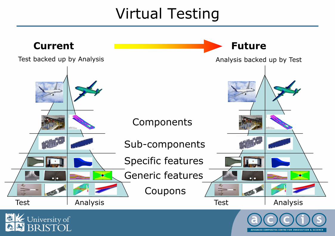
Virtual Testing
Coupons
Generic features
Specific features
Sub-components
Components
Test Analysis
Current Future
Test Analysis
Test backed up by Analysis Analysis backed up by Test
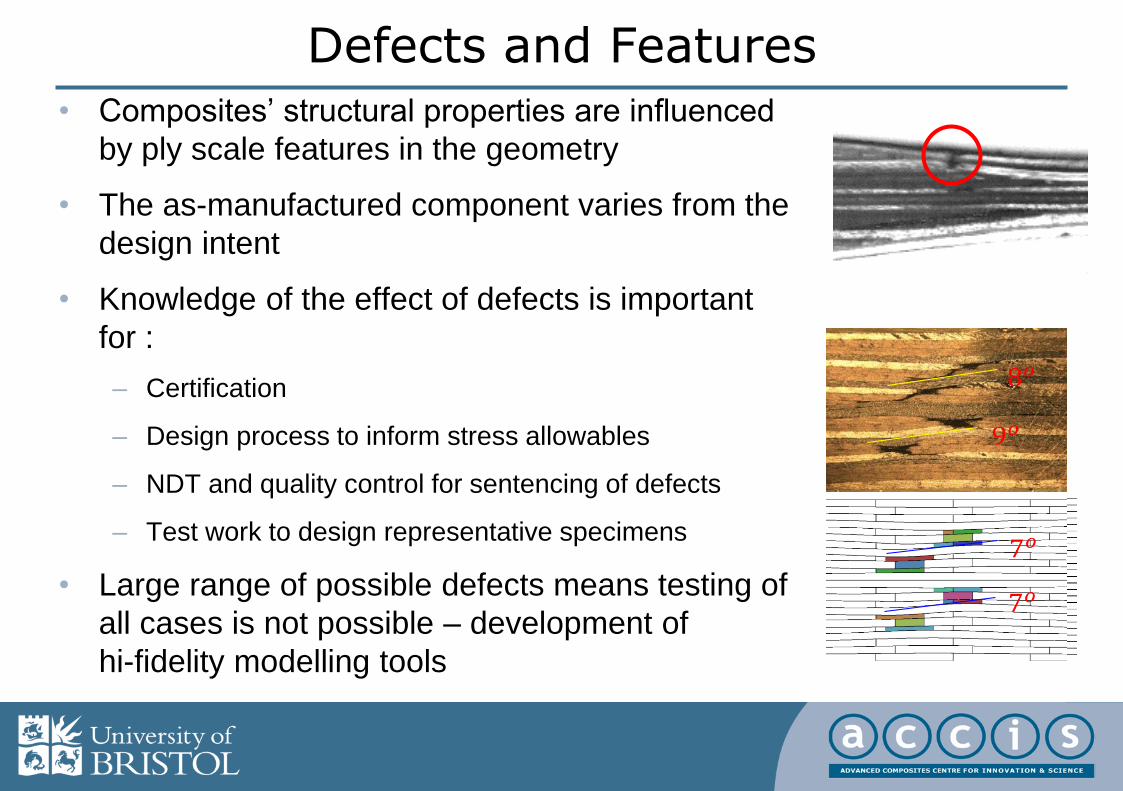
Defects and Features
• Composites’ structural properties are influenced
by ply scale features in the geometry
• The as-manufactured component varies from the
design intent
• Knowledge of the effect of defects is important
for :
– Certification
– Design process to inform stress allowables
– NDT and quality control for sentencing of defects
– Test work to design representative specimens
• Large range of possible defects means testing of
all cases is not possible – development of
hi-fidelity modelling tools

As-Manufactured Virtual Composites
• Process
modelling
• Formation
of defects
• Influence of
process
parameters
• Advanced
failure
prediction
• High fidelity
simulations
• Effect of defects
• Complex loading
• As
manufactured geometry
• Mesh creation
• Acceptance limits
• Inspection limits
6 mm
Effect of wrinkles
Ply drops and embedded delaminations
Textile composites
Process modelling
FE models from NDTdata

• Out of plane waviness
– Critical defect in terms of reduction in
compressive strength
• Gaps and overlaps
– Caused by automated tape laying process
• Delamination defects
– E.g. small inclusions or imperfections during layup
– Simplified specimen used, combined with ply drops
– Low velocity impact damage
• Voids and Porosity
Defect Types

Wrinkle Experiments
• Coupons with wrinkle angle θ (8° and 12° for tension, 10° and 12°for compression)
• Produced by varying the number of inserted 90° strips, together with pristine specimen for comparison.
0
50
100
150
200
250
300
350
400
0 0.5 1 1.5 2
Ten
sile
str
ess
(M
Pa)
Crosshead displacement (mm)
* Mukhopadhyay S., Jones M.I. & Hallett S.R. Composites 2013, Azores

Wrinkle Modelling
• Modelled with ply-by-ply hi-fidelity analysis in Abaqus/explicit
• Cohesive interface elements for delamination
• In-plane damage models for matrix cracking and fibre failure
6 mm
+45°
90°
-45°
0°
Compressive stress at final failure
* Mukhopadhyay S., Jones M.I. & Hallett S.R. Composites 2013, Azores

A
A’
B
B’
Hi-fidelity Gaps & Overlaps Modelling
preprocessor1 preprocessor2 preprocessor3 preprocessor4
A
A’
B
B’
A
A’
B
B’
preprocessor5
AA’
Improved Ply waviness by Spline curve interpolating in X, Y direction-1st derivative of waviness is continuous at every node
• Internal geometry of plies and Gaps & Overlaps features is highly complex
• Requires custom tools for generating models with Gaps & Overlaps
* Li X. et al, ICMAC, 2015, Bristol

Gaps & Overlaps Models
• Cross-section images
A
A’
A
A’
A
A’
* Li X. et al, ICMAC, 2015, Bristol

Compression Testing of Gaps and Overlaps
* Li X. et al, ICMAC, 2015, Bristol
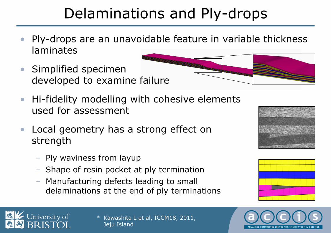
Delaminations and Ply-drops
• Ply-drops are an unavoidable feature in variable thickness laminates
• Simplified specimen developed to examine failure
• Hi-fidelity modelling with cohesive elementsused for assessment
• Local geometry has a strong effect on strength
– Ply waviness from layup
– Shape of resin pocket at ply termination
– Manufacturing defects leading to small delaminations at the end of ply terminations
* Kawashita L et al, ICCM18, 2011, Jeju Island

Ply-Level Meshing Algorithms
• As-manufactured geometries and internal features captured initially by an image-based meshing technique
• Virtual testing can then be used to augment the building block approach –here considering a wide range of delamination defect locations
* Kawashita L et al, ICCM18, 2011, Jeju Island

Virtual Testing of Defects• Example: 4mm long delaminations (NDT detection threshold) introduced
near ply terminations
• Automatic mesh generation, job submission & post-processing in a Linux cluster; hundreds of runs completed overnight
Runtime for each
slice model:
20-40 min*
*previous generation
8-core HPC node
01a
defects
resin
pockets
01b 02a 02b
03a 03a 04a 04a
05a 05a 06a 06a
07a 07a 08a 08a
* Kawashita L et al, ICCM18, 2011, Jeju Island
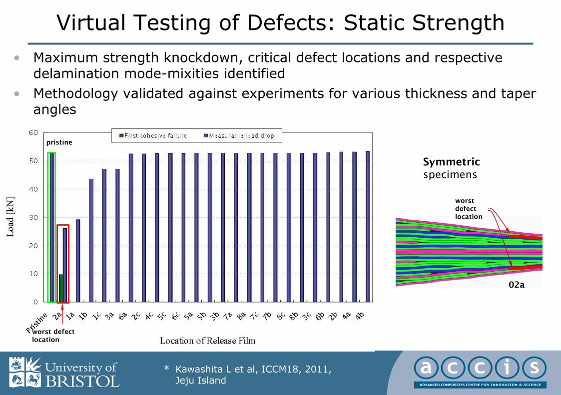
Virtual Testing of Defects: Static Strength
• Maximum strength knockdown, critical defect locations and respective delamination mode-mixities identified
• Methodology validated against experiments for various thickness and taper angles
worst
defect
location
pristine
worst defect
location
02a
Symmetric
specimens
* Kawashita L et al, ICCM18, 2011, Jeju Island

Laminated Composite Plate
Supporting Window
Indenter/ Impactor
m n
b a
d
X Y
Z
90o
0o
-45o
45o
0
1
2
3
4
5
6
0 1 2 3 4 5
Load (
kN
)
Time (ms)
FS-6J
FS-4J
* Hallett S.R. and Sun X., ICILLS,2014, Cape Town
Impact Damage
• Low velocity impact is well known for introducing delamination damage (BVID)
• This dramatically reduces the Compression After Impact (CAI) strength
• Hi-fidelity models are able to accurately predict impact damage in the form of delamination, matrix cracks and fibrefailure
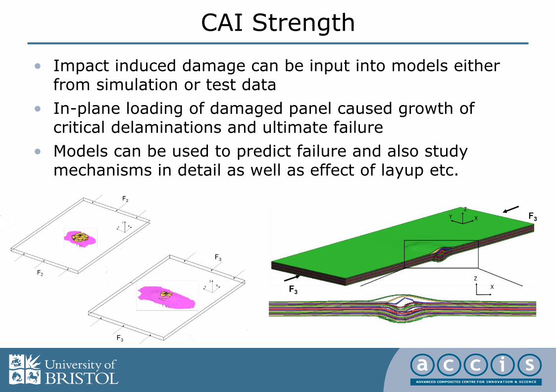
• Impact induced damage can be input into models either from simulation or test data
• In-plane loading of damaged panel caused growth of critical delaminations and ultimate failure
• Models can be used to predict failure and also study mechanisms in detail as well as effect of layup etc.
CAI Strength

Voids
• Modelling of voids is not as well advanced as other defect types
• More challenging because the exact mechanism of failure from voids is not well understood
• Most work considers the knock-down due to global void volume fraction, but not local void morphology
• Current work is focussed on the detailed understanding of failure from voids to embed into future models

Process Modelling
• As well as failure behaviour, for design it is also important to understand the origin of defects
• Modelling can be used to predict the formation of defects, especially fibre waviness
• Compaction during processsing is a major driver of the excess length needed for creation of wrinkles
• FE models recently developed that can capture this behaviour

Future Challenges
• How to model a full component when a feature model takes >500,000 elements?– Homogenised models
– Shell elements
• Bridging the length scales– Micro-meso
– Meso-macro
– Multi-scale models
• Modelling the as manufactured condition– Statistical variance
• New materials and manufacturing processes– 3D woven textiles
– Fibre placement
• Computational resource– Very large numbers of CPU
– Used efficiently
• Advanced Numerical Methods– XFEM
Related Documents


