Review Modelling bone tissue fracture and healing: a review q M. Doblar e * , J.M. Garc ıa, M.J. G omez Mechanical Engineering Department, Group of Structures and Material Modelling, Arag on Institute of Engineering Research (I3A), University of Zaragoza, Maria de Luna s/n, Zaragoza 50018, Spain Received 13 November 2002; received in revised form 27 June 2003; accepted 28 August 2003 Abstract This paper reviews the available literature on computational modelling in two areas of bone biomechanics: fracture and healing. Bone is a complex material, with a multiphasic, heterogeneous and anisotropic microstructure. The processes of fracture and healing can only be understood in terms of the underlying bone structure and its mechanical role. Bone fracture analysis attempts to predict the failure of musculoskeletal structures by several possible mechanisms under different loading conditions. However, as opposed to structurally inert materials, bone is a living tissue that can repair itself. An exciting new field of research is being developed to better comprehend these mechanisms and the mechanical behaviour of bone tissue. One of the main goals of this work is to demonstrate, after a review of computational models, the main similarities and differences between normal engineering materials and bone tissue from a structural point of view. We also underline the importance of computational simulations in biomechanics due to the difficulty of obtaining experimental or clinical results. Ó 2003 Elsevier Ltd. All rights reserved. Keywords: Biomechanics; Bone fracture; Fracture healing; Computational simulation Contents 1. Introduction ........................................................ 1811 2. Basic concepts of bone biology ........................................... 1812 3. Bone mechanical properties ............................................. 1815 4. Mechanisms of bone fracture ............................................ 1817 5. Bone fracture criteria .................................................. 1820 q Research partially supported by Diputaci on General de Arag on, project P-008/2001. * Corresponding author. Tel.: +34-9767-61912; fax: +34-9767-62578. E-mail address: [email protected] (M. Doblar e). 0013-7944/$ - see front matter Ó 2003 Elsevier Ltd. All rights reserved. doi:10.1016/j.engfracmech.2003.08.003 Engineering Fracture Mechanics 71 (2004) 1809–1840 www.elsevier.com/locate/engfracmech

Welcome message from author
This document is posted to help you gain knowledge. Please leave a comment to let me know what you think about it! Share it to your friends and learn new things together.
Transcript

Engineering Fracture Mechanics 71 (2004) 1809–1840
www.elsevier.com/locate/engfracmech
Review
Modelling bone tissue fracture and healing: a review q
M. Doblar�e *, J.M. Garc�ıa, M.J. G�omez
Mechanical Engineering Department, Group of Structures and Material Modelling, Arag�on Institute of Engineering Research (I3A),
University of Zaragoza, Maria de Luna s/n, Zaragoza 50018, Spain
Received 13 November 2002; received in revised form 27 June 2003; accepted 28 August 2003
Abstract
This paper reviews the available literature on computational modelling in two areas of bone biomechanics: fracture
and healing. Bone is a complex material, with a multiphasic, heterogeneous and anisotropic microstructure. The
processes of fracture and healing can only be understood in terms of the underlying bone structure and its mechanical
role.
Bone fracture analysis attempts to predict the failure of musculoskeletal structures by several possible mechanisms
under different loading conditions. However, as opposed to structurally inert materials, bone is a living tissue that can
repair itself. An exciting new field of research is being developed to better comprehend these mechanisms and the
mechanical behaviour of bone tissue.
One of the main goals of this work is to demonstrate, after a review of computational models, the main similarities
and differences between normal engineering materials and bone tissue from a structural point of view. We also underline
the importance of computational simulations in biomechanics due to the difficulty of obtaining experimental or clinical
results.
� 2003 Elsevier Ltd. All rights reserved.
Keywords: Biomechanics; Bone fracture; Fracture healing; Computational simulation
qRe*Co
E-m
0013-7
doi:10.
Contents
1. Introduction . . . . . . . . . . . . . . . . . . . . . . . . . . . . . . . . . . . . . . . . . . . . . . . . . . . . . . . . 1811
2. Basic concepts of bone biology . . . . . . . . . . . . . . . . . . . . . . . . . . . . . . . . . . . . . . . . . . . 1812
3. Bone mechanical properties . . . . . . . . . . . . . . . . . . . . . . . . . . . . . . . . . . . . . . . . . . . . . 1815
4. Mechanisms of bone fracture . . . . . . . . . . . . . . . . . . . . . . . . . . . . . . . . . . . . . . . . . . . . 1817
5. Bone fracture criteria . . . . . . . . . . . . . . . . . . . . . . . . . . . . . . . . . . . . . . . . . . . . . . . . . . 1820
search partially supported by Diputaci�on General de Arag�on, project P-008/2001.
rresponding author. Tel.: +34-9767-61912; fax: +34-9767-62578.
ail address: [email protected] (M. Doblar�e).
944/$ - see front matter � 2003 Elsevier Ltd. All rights reserved.
1016/j.engfracmech.2003.08.003

Nome
Emrc
rt
qa
aBVTV
qt
qn�nXij
adDKDNNf
ri
rij
Fi; FijA
Gij; Firþi
r�i
sijNi
civtmw�fprolifer
1810 M. Doblar�e et al. / Engineering Fracture Mechanics 71 (2004) 1809–1840
6. Modelling traumatic and pathologic fractures. . . . . . . . . . . . . . . . . . . . . . . . . . . . . . . . . 1824
7. Bone fracture healing . . . . . . . . . . . . . . . . . . . . . . . . . . . . . . . . . . . . . . . . . . . . . . . . . . 1825
8. Conclusions. . . . . . . . . . . . . . . . . . . . . . . . . . . . . . . . . . . . . . . . . . . . . . . . . . . . . . . . . 1833
References . . . . . . . . . . . . . . . . . . . . . . . . . . . . . . . . . . . . . . . . . . . . . . . . . . . . . . . . . . . . . 1834
nclature
elastic modulus
Poisson�s ratiocompression strength
tension strengthapparent ash density
ash fraction
bone volume fraction
true tissue density
bone apparent density
bone porosity
directional bone porosity defined in Eq. (10)
symmetric traceless tensor that describes the porosity distributionthe crack length
the average spacing of bone cement lines
range of cyclic stress density [115]
unidimensional damage variable
number of cycles
number of cycles to failure
principal stresses
stress componentstensors that define Tsai–Wu quadratic failure criterion
fabric tensor that takes account the bone mass distribution
jkm tensors used by Cowin [18] in order to define the Tsai–Wu failure criterion
ultimate strength in tension along the principal direction iultimate strength in compression along the principal direction istress deviatoric tensor
number of cells for each cell type i (where subscripts �s�, �b�, �f� and �c� indicate stem cells,
osteoblasts, fibroblasts and chondrocytes respectively)cell concentration for each cell type iboundary growth rate
time that cells need to differentiate (maturation time)
mechanical stimulus that controls the evolution of the different cellular events
ationðx;wÞ function that defines the number of stem cells that proliferate and cause the callus
growth

fproliferationðcs; x;wÞ function that defines the number of stem cells that proliferate causing an increase
of the concentrationfmigrationðcs; xÞ function that defines how stem cells migrate
fdifferentiationðx;w; tmÞ function that characterizes how stem cells differentiate into specialized cells
ggrowthðx;w;tmÞ function that quantifies the change of volume that chondrocytes experiment by swelling
hdifferentiationðw; tmÞ function that determines the evolution of osteoblast population produced by in-
tramembranous ossification
hremodellingðwÞ function that estimates the rate of osteoblast population by endochondral ossification
pi proportion in volume of each component i (where each subscript means mi: mineral, cI:
collagen type I, cII: collagen type II, cIII: collagen type III, gs: ground substance)
M. Doblar�e et al. / Engineering Fracture Mechanics 71 (2004) 1809–1840 1811
1. Introduction
The main role of the musculoskeletal system is to transmit forces from one part of the body to another
under controlled strain and to protect vital organs (e.g. lungs, brain). It also performs other important
functions such as serving as mineral reservoir.
Several skeletal tissues participate in this mechanical objective of transmission and protection: bone,
cartilage, tendons, ligaments and muscles. Bone mainly determines global structural stiffness and strength,
whereas other tissues transmit loads between bones. The mechanical properties of bone are a result ofa compromise between the need for a certain stiffness (to reduce strain and achieve a more efficient kine-
matics), and the need for enough ductility to absorb impacts (to reduce the risk of fracture and minimize
skeletal weight).
As a result of this compromise, thousands of years of evolution have produced a complex, multiphasic,
heterogeneous, anisotropic microstructure. In the first section of this paper we present the main aspects of
bone biology in terms of its mechanical properties and constitutive behaviour. Another important aspect of
bone behaviour is its self-adaptive capacity, modifying its microstructure and properties according to the
specific mechanical environment. Bone is not like inert engineering materials. It undergoes substantialchanges in structure, shape and composition according to the mechanical and physiological environment,
an adaptive process known as bone remodelling. A brief explanation of the basic aspects of bone re-
modelling is included in Section 2.
Bone adaptability allows for efficient repair, which in turn helps to prevent fractures. However, fractures
are still quite common, usually caused by the sudden appearance of a load that exceeds bone strength, or
the cyclic activity of loads (well below bone strength) that gradually accumulate damage at a rate that
cannot be repaired. The stiffness and strength of the bone are reduced until a failure of the first type occurs
under a much lower load. Predicting and preventing bone fractures is an important topic in orthopaedicsdue to their high frequency, surgical complications and socio-economic impact. For example, the number
of hip fractures world-wide was estimated to be 1.66 million in 1990 and expected to increase to 6.26 million
by 2050 [1]. In the third section of this paper we review the main studies and models developed to predict
bone fractures.
Once a fracture occurs, the basic healing process is auto-activated naturally to repair the site. Healing
involves the differentiation of several tissues (cartilage, bone, granulation, etc.), with different patterns that
are directly influenced by the mechanical environment, which is in turn governed by the load applied and
the stability of the fracture site. In fact, not all fractures are completely repaired. Sometimes there are non-unions or delayed fractures depending on specific geometric, mechanical and biological factors, justifying
the many different kinds of fixations used to improve fracture stabilisation. In Section 4 we review the
fracture healing process and the different computer simulation models.

1812 M. Doblar�e et al. / Engineering Fracture Mechanics 71 (2004) 1809–1840
Finally, the last section includes important conclusions on modelling bone fracture and fracture healing,
indicating the main new trends.
2. Basic concepts of bone biology
Bone tissue has very interesting structural properties. This is essentially due to the composite structure of
bone, composed by hydroxyapatite, collagen, small amounts of proteoglycans, noncollagenous proteins
and water [2–5]. Inorganic components are mainly responsible for the compression strength and stiffness,while organic components provide the corresponding tension properties. This composition varies with
species, age, sex, the specific bone and whether or not the bone is affected by a disease [6]. Another im-
portant aspect that also characterizes this peculiar mechanical behaviour of bone is its hierarchical orga-
nization. Weiner and Wagner [2] described this, starting from the nanometric level and ending at the
macroscopic levels, relating the latter to the mechanical properties.
From a macroscopic point of view, bone tissue is non-homogeneous, porous and anisotropic. Although
porosity can vary continuously from 5 to 95%, most bone tissues have either very low or very high porosity.
Accordingly, we usually distinguish between two types of bone tissue (see Fig. 1). The first type is trabecularor cancellous bone with 50–95% porosity, usually found in cuboidal bones, flat bones and at the ends of
long bones. The pores are interconnected and filled with marrow (a tissue composed of blood vessels, nerves
and various types of cells, whose main function is to produce the basic blood cells), while the bone matrix
has the form of plates and struts called trabeculae, with a thickness of about 200 lm and a variable
arrangement [7].
The second type is cortical or compact bone with 5–10% porosity and different types of pores [9].
Vascular porosity is the largest (50 lm diameter), formed by the Haversian canals (aligned with the long
axis of the bone) and Volkmanns�s canals (transverse canals connecting Haversian canals) with capillariesand nerves. Other porosities are associated with lacunae (cavities connected through small canals known as
canaliculi) and with the space between collagen and hydroxyapatite (very small, around 10 nm). Cortical
bone consists of cylindrical structures known as osteons or Haversian systems (see Fig. 2), with a diameter
of about 200 lm formed by cylindrical lamellae surrounding the Haversian canal. The boundary between
the osteon and the surrounding bone is know as the cement line.
Fig. 1. Bone section showing cortical and trabecular bone (From [8] with permission).

Fig. 2. Microscopical structure of cortical bone. (a) 3D sketch of cortical bone, (b) cut of a Haversian system, (c) photomicrograph of
a Haversian system (From [11] with permission).
M. Doblar�e et al. / Engineering Fracture Mechanics 71 (2004) 1809–1840 1813
Cortical bone is usually found in the shafts of long bones and surrounding the trabecular bone forming
the external shell of flat bones. This combination of trabecular and cortical bone forms a ‘‘sandwich-type’’
structure, well known in engineering for its optimal structural properties [10].
Throughout their useful life, both types of bone are formed by two different tissues: woven and lamellar
bone. The skeletal embryo consists of woven bone, which is later replaced by lamellar bone. Normally there
is no woven bone in the skeleton after four or five years but it reappears during the healing process afterfracture. The two types of bone have many differences in composition, organization, growth and me-
chanical properties. Woven bone is quickly formed and poorly organized with a more or less random
arrangement of collagen fibers and mineral crystals. Lamellar bone is slowly formed, highly organized and
has parallel layers or lamellae that make it stronger than woven bone.
Bones can grow, modify their shape (external remodelling or modelling), self-repair when fractured
(fracture healing) and continuously renew themselves by internal remodelling. All these processes are
governed by mechanical, hormonal and physiological patterns. Growth and modelling mostly occur during
childhood, fracture healing only occurs during fracture repair and internal remodelling occurs throughoutour lifetime, playing a fundamental role in the evolution of the bone microstructure and, consequently, in
the adaptation of structural properties and microdamage repair.
Bone remodelling only occurs on the internal surfaces of the bone matrix (trabecular surfaces of
cancellous bone and Haversian systems of cortical bone). Bone can only be added or removed by bone
cells on these surfaces. There are four types of bone cells, which can be classified according to their
functions.

1814 M. Doblar�e et al. / Engineering Fracture Mechanics 71 (2004) 1809–1840
Osteoblasts are the differentiated mesenchymal cells that produce bone. They are created at the peri-
osteum layer or stromal tissue of bone marrow.
Osteoclasts remove bone, demineralizing it with acid and dissolving collagen with enzymes. These cells
originate from the bone marrow.Bone lining cells are inactive osteoblasts that are not buried in new bone. They remain on the surface
when bone formation stops and can be reactivated in response to chemical and/or mechanical stimuli [12].
Like bone lining cells, osteocytes are former osteoblasts that are buried in the bone matrix. They are
located in lacunae [9] and communicate with the rest of cells via canaliculi. Many authors [13–16] suggest
that osteocytes are the mechanosensor cells that control bone remodelling, but this has not been proven yet.
Furthermore, it is quite reasonable to assume that osteocytes, the only cells embedded in the bone matrix,
are affected by processes that damage the bone matrix. Matrix disruption may be expected to directly injure
osteocytes, disrupting their attachments to bone matrix, interrupting their communication through cana-licular or altering their metabolic exchange. Fatigue microdamage may therefore create a situation re-
sembling disuse at the level of the osteocyte cell body and lead to bone remodelling starting with osteoclast
recruitment.
The remodelling process is not performed individually by each cell, but by groups of cells functioning as
organized units, which Frost named ‘‘basic multicellular units’’ (BMUs) [17]. They operate on bone peri-
osteum, endosteum, trabecular surfaces and cortical bone, replacing old bone by new bone in discrete
Fig. 3. A–R–F sequence in cortical bone (a) and in trabecular bone (b) (From [11] with permission).

M. Doblar�e et al. / Engineering Fracture Mechanics 71 (2004) 1809–1840 1815
packets. The BMUs always follow a well-defined sequence of processes, normally known as the A–R–F
sequence: activation–resorption–formation (Fig. 3).
Bone is also anisotropic. Cortical bone has a very low porosity and its anisotropy is mainly controlled by
lamellar and osteonal orientation. On the contrary, trabecular bone has a higher porosity and its anisotropyis determined by trabecular orientation. It is difficult to quantify anisotropy experimentally. In fact, only
recently have several measures of bone mass directional distribution been proposed for trabecular bone.
Cowin [18] defines bone anisotropy by means of the so-called fabric tensor: a second order tensor that
defines the principal values and directions of the bone mass distribution (for different ways of measuring the
fabric tensor see also [19–22]).
In fact, structural anisotropy has a direct influence on stiffness properties as well as strength. For
example, the average strength of a compact human bone in Reilly and Burstein [23] was 105 MPa in a
longitudinal compression test, and 131 MPa in a transversal compression test. The average longitudinalstrength in tension in the same experiment was 53 MPa.
3. Bone mechanical properties
As shown in Section 2, the mechanical properties of bone depend on composition and structure.
However, composition is not constant in living tissues. It changes permanently in terms of the mechanical
environment, ageing, disease, nutrition and other factors. Many reports try to correlate mechanical
properties with composition [24–29]. Vose and Kubala [30] were possibly the first to quantify how much
mechanical properties depend on composition, obtaining a correlation between ultimate bending strength
and mineral content. One of the most cited works is Carter and Hayes [24], who found that elastic modulus
and the strength of trabecular and cortical bone are closely related to the cube and square of the apparent
wet bone density, respectively.Although these preliminary models only took into account the apparent density, several authors [10,31–
34] have shown that the mechanical properties of cortical and cancellous bone depend on apparent density
and mineral content. The most representative compositional variable is the ash density with the following
correlation:
E ðMPaÞ ¼ 10500 � q2:57�0:04a rc ðMPaÞ ¼ 117 � q1:93�0:04
a ð1Þ
where qa is ash density. This expression explains over 96% of the statistical variation in the mechanicalbehaviour of combined vertebral and femoral data over the range of ash density (0.03–1.22 g cm�3).
Keyak et al. [35] also studied the relationship between mechanical properties and ash density for
trabecular bone, obtaining the following expressions with 92% correlation:
E ðMPaÞ ¼ 33900 � q2:2a if qa 6 0:27 g cm�3
rc ðMPaÞ ¼ 137 � q1:88a if qa 6 0:317 g cm�3
�ð2Þ
One limitation of these models is that they do not separate the influence of bone volume fraction from the
ash fraction. So, Hern�andez et al. [36] express the apparent density as a function of the bone volume
fraction (bone volume/total volume) and the ash fraction (a):
q ¼ BV
TVqt ¼
BV
TVð1:41þ 1:29aÞ ð3Þ
where qt is the true tissue density of the bone, that is linearly related to the ash fraction a. They determined
the elastic modulus and compressive strength, independently of bone volume fraction and ash fraction, witha 97% correlation:
1816 M. Doblar�e et al. / Engineering Fracture Mechanics 71 (2004) 1809–1840
E ðMPaÞ ¼ 84370 BVTV
� �2:58�0:02a2:74�0:13
rc ðMPaÞ ¼ 749:33 BVTV
� �1:92�0:02a2:79�0:09
(ð4Þ
In these expressions, the exponent related to ash fraction is larger than that associated with bone volumefraction, suggesting that a change in mineral content will produce a larger change in mechanical properties.
We have focused on compression strength because the ultimate tension strength of bone tissue is usually
established as a percentage of the compression strength. Different values have been used for this ratio, from
0.33 to 0.7 in bovine trabecular bone [37,38], to 0.5 to 0.7 for human cortical bone, depending on the test
direction [23]. Keyak and Rossi [39] performed a FE analysis on the influence of this parameter and found
that the best agreement was between 0.7 and 1. However, they considered that the parameter was constant,
even though it should also depend on structural variables, as suggested by Keaveny et al. [37,40].
Although all these correlations can predict the main mechanical properties, they do not consider theinfluence of structural and microstructural features or the different behaviours in each direction. This aspect
was first considered by Lotz et al. [41]. They determined the Young�s modulus and the compressive strength
of cortical and trabecular femoral bone in the axial and transversal directions using the apparent density as
a control variable. The elastic modulus and the compressive strength for cortical femoral bone in the axial
direction was approximated by
E ðMPaÞ ¼ 2065 � q3:09 rc ðMPaÞ ¼ 72:4 � q1:88 ð5Þ
and in the transversal direction by the correlationE ðMPaÞ ¼ 2314 � q1:57 rc ðMPaÞ ¼ 37 � q1:51 ð6Þ
Similarly, the compressive strength for trabecular bone was defined as,E ðMPaÞ ¼ 1904 � q1:64 ðaxial directionÞ1157 � q1:78 ðtransversal directionÞ
�ð7Þ
rc ðMPaÞ ¼ 40:8 � q1:89 ðaxial directionÞ21:4 � q1:37 ðtransversal directionÞ
�ð8Þ
A different idea was suggested by Pietruszczak et al. [42], who included the directional dependence of
strength using the expression:
rcðlÞ ¼ rc0
1� nðlÞ1� n0
� �c
ð9Þ
where n0, rc0 are reference properties (the first is the average porosity, and the second the corresponding
strength for this level of porosity), c a constant in the interval ð1; 2Þ, and �nðlÞ is the directional porosity that
can be approximated as
nðlÞ � nð1þ XijliljÞ ð10Þ
being n the average porosity, li the orientation relative to a fixed Cartesian coordinate system and Xij
a symmetric traceless tensor, which describes the distribution of voids.
These mathematical relationships have been used to predict proximal femoral fractures with finite ele-
ments. The 3D finite element model is generated from a geometrical model usually recovered from a CT
scan of the specific organ. It is also calibrated in terms of K2HPO4 equivalent density. Then apparent
density, porosity or apparent ash density are estimated using different correlations to model the hetero-
genous distribution of mechanical properties. Most models consider isotropic behaviour, since it is notpossible to quantify the whole anisotropic structure of a bone organ with current techniques. Only [42]
includes this effect in femoral fracture simulations, but with a spatially constant anisotropy ratio, even

M. Doblar�e et al. / Engineering Fracture Mechanics 71 (2004) 1809–1840 1817
though it changes widely in the femur at different locations [21,43]. One way to overcome this limitation is
to employ anisotropic internal bone remodelling models [44–48] that can predict density and anisotropy
distribution, and some of them with sufficient accuracy.
Another assumption of most FE analyses in the literature is the linearity of the constitutive behaviour ofbone tissue. This is usually accurate enough, but some authors obtain more accurate results by considering
nonlinear material properties for cortical and trabecular bone [49,50].
An additional limitation is the lack of analyses on fracture initiation and growth until complete failure.
Most studies obtain a stress distribution and a possible fracture load. The extension of the principles of
Fracture Mechanics to bone fracture analysis is clearly underdeveloped, although it will probably be an
important research field in the near future.
4. Mechanisms of bone fracture
The first mechanism of bone fracture appears when an accidental load exceeds the physiological range,
inducing stresses over the strength that bone tissue has achieved after adaptation during growth and de-
velopment (traumatic fracture). Following the clinical literature [51–53], there are two main causes for this
type of fracture: an external impact produced, for example, by a fall, or fractures that occur ‘‘spontane-
ously’’ by a muscular contraction without trauma (see Fig. 4). The latter are quite common in elderly
people with osteoporosis. Several authors suggest that the main cause of hip fracture is contraction of the
iliopsoas muscle and gluteus medius [53,54].
This kind of fracture is often produced by normal loads acting on a bone that has been weakened bydisease or age [55]. This type of fracture is normally called pathologic. Most are provoked by osteoporosis
in the elderly and are more frequent in women than men. Another important cause of pathologic fractures
are bone tumours, which modify bone mechanical properties and produce stress concentrators. Removing
the tumour usually increases the risk of fracture. In fact, the higher risk of bone fracture in the elderly is not
only due to the progressive reduction of bone consistency (osteoporosis), and therefore strength, but also to
additional factors such as the inability of soft tissues to absorb the energy generated in a fall and the change
Fig. 4. Scheme of two usual mechanisms of bone fracture.

1818 M. Doblar�e et al. / Engineering Fracture Mechanics 71 (2004) 1809–1840
of the kinematic variables of the gait. Lotz and Hayes [56] report that only a small amount of energy is
needed to break a bone (i.e. 5% of the energy available in a fall), what is due to the energy absorbing action
of soft tissues that are deformed in the impact.
The second type of fracture is produced by creep or fatigue. Bones often support more or less constantloads for prolonged periods of time and cyclic loads that may produce microdamage. If the accumulation of
microdamage is faster than repair by remodelling, microcracks (or other kinds of microdamage) can
multiply to produce macrocracks and complete fracture. Clinically, this is called a stress fracture. It nor-
mally occurs in individuals who have increased repetitive-type physical activities such as soldiers, ballet
dancers, joggers, athletes and racehorses [7,57–59]. It also occurs at lower activity levels in bones weakened
by osteoporosis, especially at advanced ages when bone remodelling is almost inactive.
Many experimental [60–64] and theoretical [58,59,65–71] works have suggested that bone tissue can
repair microdamage by remodelling. Indeed, some authors consider that the accumulation of microdamageis the mechanical stimulus for remodelling [66,69,70,120,121].
However, the prevention of stress fractures does not only depend on repair by remodelling. It is also
controlled by the specific process of crack initiation and propagation. The microstructure of cortical bone is
similar to fiber-reinforced composite materials. Osteons are analogous to fibers, interstitial bone tissue is
analogous to the composite matrix and the cement line acts as a weak interface where cracks may initiate
[72]. Many authors have tried to explain the mechanical behaviour of cortical bone tissue through com-
posite models. Katz [73] considers the anisotropy of cortical moduli using a hierarchical composite model
of osteons made of hollow, right circular cylinders of concentric lamellae. Crolet et al. [74] appliedhomogenization techniques to develop a hierarchical osteonal cortical bone model with several levels of
microstructure: osteons, interstitial bone, and layers of lamellae with collagen fibers and hydroxyapatite.
The results obtained agree well with the experimental data. Other authors suggest that osteons increase the
toughness and fatigue resistance of cortical bone [71,75–79]. For example, Corondan and Haworth [79]
found that crack propagation in bone is inhibited by more or larger osteons. Prendergast and Huiskes [80]
also employed microstructural finite element analysis (FEA) to explore the relationship between damage
formation and local strain of osteocyte containing lacunae for various types of damage. The high local
strain around lacuna formed stress bands between lacunae, providing sites for crack nucleation and pathsfor crack growth, effectively unloading the lacunae adjacent to the damaged region.
Linear elastic fracture mechanics (LFM) have also been used widely to characterize bone resistance to
fracture [76,81–87] by measuring the fracture toughness of cortical bone under various loading modes (see
Table 1). However, changes in fracture toughness with age, microstructure and composition are not always
the same in different species or bone locations in the same species, as shown by Yeni and Norman [88]. Only
a few studies have addressed the fracture mechanics of microcracks in osteonal cortical bone [77,89,90]
by analysing the interaction between microcracks and the distribution and type of osteon.
In general, fractures are caused by two main mechanisms: when the damage rate exceeds the remodel-ling/repair rate (excess damage) or when a normal damage rate is not repaired properly due to a defective
remodelling/repair mechanism (deficient repair).
Damage accumulation in bone is similar to artificial structural materials. Schaffler et al. [93,94] showed
that fatigue damage is similar in vitro and in vivo. The microdamage (related to the load and number of
cycles), may appear in different ways at the microstructural level: debonding of the collagen–hydroxiapatite
composite [95], slipping of lamellae along cement lines [96], cracking along cement lines or lacunae [97,98],
shear cracking in cross-hatched patterns [99] and progressive failure of the weakest trabeculae [100]. At the
macroscopic level damage is hardly visible before there is a large crack and global failure, even though themechanical functionality may have altered substantially in earlier stages. In general, the evolution of mi-
crodamage during cyclic loading can be quantified in four ways [101] by measuring: (1) defects at microscale
(number/density of cracks), (2) changes in different properties (material density, acoustic emission re-
cordings, electrical resistivity, ultrasonic waves, microhardness measurements, etc.), (3) the remaining life to

Table 1
Experimental measures of Kc and Gc for cortical bone (from [7,10])
Bone type Kc (MPam1=2) Gc (Jm�2)
Mode I: Transverse fracture
Bovine femur [81] 5.49 3100–5500
Bovine tibia [82] 2.2–4.6 780–1120
Equine metacarpus [83] 7.5 2340–2680
Human tibia [84] 2.2–5.7 350–900
Mode I: Longitudinal fracture
Bovine femur [81] 3.21 1388–2557
Bovine femur [91] 2.4–5.2 920–2780
Bovine tibia [85] 2.8–6.3 630–2238
Human femur [84] 2.2–5.7 350–900
Human tibia [76] 4.32–4.05 897–595
Human tibia [92] 3.7 360
Mode II
Human tibia [84] 2.2–2.7 365
M. Doblar�e et al. / Engineering Fracture Mechanics 71 (2004) 1809–1840 1819
failure, and (4) variations of macromechanical behaviour (changes in elastic, plastic or viscoplastic prop-erties). The last measurement is often used to quantify fatigue cycling by a macroscopic analysis of stiffness,
strength and creep relaxation [93,94,102–110], in addition to other methods [103,109–114].
Taylor and Prendergast [115] express the crack growth rate in terms of the cyclic stress intensity and
crack length, concluding that the crack growth rate decreases rapidly with increasing length. This behaviour
is typical of short-crack fatigue in many materials and can be interpreted in terms of microstructural
barriers to growth. They propose the following equation for compact bone:
dadN
¼ fCðDK � DKthÞng þ C0DKn0 d � ad
� �m� �ð11Þ
where symbols {} means
fAg ¼ A for AP 00 for A < 0
�ð12Þ
and a is the crack length, d the average spacing of cement lines, DK is the range of cyclic stress density and
the rest of parameters are constants determined by Prendergast and Taylor [115]. The first term describes
the behaviour of cracks when they are long, and the second one is used for short cracks.
Carter and Caler [109,110,116] propose a damage variable, D, between 0 and 1, that increases at a rate
inversely proportional to the number of cycles to failure Nf :
dDdN
¼ 1
Nf
ð13Þ
that is, a remaining lifetime criterion that identifies the damage level with proximity to failure. One of the
main disadvantages is that it does not account for the current damage state or stress history.
Several years later, Zioupos et al. [117] and Pattin et al. [118] defined damage as the ratio between the
elastic modulus in the current and the initial state:
D ¼ 1� EE0
ð14Þ
depending on the stress history and the mechanical properties of the material. In fact, the accumulated
damage at each stress level is a non-linear function of the number of cycles [117,118].

1820 M. Doblar�e et al. / Engineering Fracture Mechanics 71 (2004) 1809–1840
Many theoretical models have been developed in order to predict the accumulation of microdamage in
bone. Recently Davy and Jepsen [119] have performed a detailed revision of the most important contri-
bution in this field.
It is important to understand that fatigue failure is not only prevented by lamellar structure but also byremodelling. Several theories have been developed to explain how bone remodelling is activated by damage
and mechanical load. The models hypothesise that bone tries to optimise strength and stiffness by regu-
lating porosity and local damage generated by fatigue or creep.
Martin and co-workers have proposed several models where bone remodelling is activated by damage
produced by fatigue or creep [66,70,120]. In their last work [66], a more realistic theory is proposed that
includes the most important mechanical and biological processes. It assumes that bone remodelling is
controlled by packets of cells, so-called BMUs. The BMUs act in a sequence of events that require three to
four months based on measurements from biopsies. The events control the remodelling response and de-pend on the mechanical environment, microdamage accumulation and the surface available for remodel-
ling.
Prendergast and Taylor [69] proposed a full bone internal remodelling model where damage occurs as a
microcrack distribution even in the equilibrium situation. The stimulus that controls repair is the difference
between the actual damage and the damage in the equilibrium situation. Ramtani and Zidi [121] also
propose a model to explain the physiological process of couple damaged-bone remodelling, following the
general framework of continuum thermodynamics.
Skeletal biomechanics is more and more focused on how skeletal tissues are produced, maintained andadapted as an active response to biophysical stimuli in their environment, currently known as mechano-
biology [122]. Now that the human genome has been sequenced, it is apparent that the genetic code is only
the beginning. It provides few answers about how skeletal tissues are generated and maintained. This
emphasises the importance of understanding the role of environmental influence, especially mechanical
factors. The development of mechanobiology will bring great benefits to tissue engineering and to the
treatment and prevention of different skeletal problems, such as congenital deformities, osteoporosis,
osteoarthritis and bone fractures.
5. Bone fracture criteria
Different fracture criteria have been proposed for bone tissue and many experiments have been per-
formed to validate them [37,40,123–127]. Many reports use FE models to evaluate fracture patterns andloads in terms of fracture criteria, especially in the proximal femur [39,125,128–131]. Here we review the
most important criteria and their limitations.
The Von Mises–Hencky formula is an isotropic criterion traditionally used to predict yielding of ductile
materials like metals. It assumes equal strength (ultimate stress) in tension and compression, which is not
very realistic in bone tissue. Failure results when the equivalent Von Mises–Hencky stress equals the
ultimate strength of the material
ffiffiffiffiffiffiffiffiffiffiffiffiffiffiffiffiffiffiffiffiffiffiffiffiffiffiffiffiffiffiffiffiffiffiffiffiffiffiffiffiffiffiffiffiffiffiffiffiffiffiffiffiffiffiffiffiffiffiffiffiffiffiffiffiffiffiffiffiffiffiffiffiffiðr2 � r3Þ2 þ ðr3 � r1Þ2 þ ðr1 � r2Þ2q¼ rc ð15Þ
with ri principal stresses and rc the ultimate strength in compression (or tension).
Although this criterion is not very realistic, it has been widely used for estimating proximal femoral
fracture load and assessing hip fracture risk [39,126,128,129,132]. In fact, Keyak et al. [39] analysed that,
when isotropic material properties are used, the Von Mises–Hencky criterion may be the most accurate for
predicting fracture location, even after accounting for differences in the tensile and compressive strengthof bone.

M. Doblar�e et al. / Engineering Fracture Mechanics 71 (2004) 1809–1840 1821
However, the experimental results obtained by Fenech and Keaveny [123] for bovine trabecular bone
indicated that the Von Mises–Hencky criterion was not a good predictor of fracture load in trabecular
bone, particularly when the stress state was dominated by shear.
Hoffman (1967) [164] proposed a fracture criterion for brittle materials that also takes into account thedifferent strength in tension and compression. Nevertheless, it assumes the same behaviour in all directions:
C1ðr2 � r3Þ2 þ C2ðr3 � r1Þ2 þ C3ðr1 � r2Þ2 þ C4r1 þ C5r2 þ C6r3 ¼ 1 ð16Þ
where ri are the principal stresses, Ci material parameters defined as C1 ¼ C2 ¼ C3 ¼ 12rtrc
; C4 ¼ C5 ¼ C6 ¼1rt� 1
rc, and rc, rt are the ultimate strengths in compression and in tension, respectively. In expression (16),
the linear terms represent the difference between tension and compression. The Hoffman criterion is
equivalent to the Von Mises–Hencky criterion when rc ¼ rt.
This criterion has been also used to predict load and pattern of proximal femoral fractures [39,132]
obtaining results slightly worse than the Von Mises–Hencky criterion.The maximum stress criterion (Rankine criterion) was initially introduced to predict failure of brittle
materials. It assumes that failure takes places when the highest principal stress exceeds the ultimate strength
in tension or compression. Keyak and Rossi [39] used it to predict the ultimate fracture load of bone tissue
with less than 30% error in all cases. The parallel criterion in strains (Saint–Venant criterion) is even more
correlated with the experimental data (less than 20% error), which is also a well-known situation in brittle
materials. Fenech and Keaveny [123] were able to predict the failure of trabecular bone reasonably well
using the principal strain criterion.
Keyak and Rossi [39] also obtained reasonably accurate results with the maximum shear stress (alsoknown as the Tresca theory) and the maximum shear strain criteria.
The Mohr–Coulomb criterion is commonly used for materials with different behaviour in tension and
compression, such as soils [133]. It is an isotropic criterion that is expressed as follows for non-cohesive
materials, in the space of principal stresses:
r1
rt
� r3
rc
¼ 1 ð17Þ
where r1 P r2 P r3 are the principal stresses and rc, rt the ultimate strengths in compression and tension
(rt ¼ arc), respectively. Keyak and Rossi [39] used this criterion to predict the ultimate fracture load of
bone tissue. It agreed well with the experimental data when coefficient a tended to one. For smaller values,
the results are on the safety side, that is, the predicted fracture load is always lower than the experimental
one [128].
The modified Mohr–Coulomb criterion solves some of the original problems [133]. It is expressed as
rtr1¼ 1 when r1
r36 � 1
rc�rtrcrt
� r1 � r3rc¼ 1 otherwise
�ð18Þ
This criterion was used to predict fracture load due to a fall [39]. The results were better than the standardMohr–Coulomb when coefficient a was low, but worse when a was above 0.5.
Other authors have tried to validate experimental tests using cellular solid multiaxial criteria [123,127].
These models are better than their predecessors but very difficult to implement in a general way for FE
analyses of whole bones. They could be very useful to validate other more phenomenological criteria.
The Tsai–Wu quadratic criterion [134] is an obvious candidate for a multiaxial anisotropic failure cri-
terion since it accounts for strength asymmetry (different tensile and compressive strengths) and anisotropy,
as well as interactions between strengths under different loading conditions. Tsai and Wu [134] expressed
this criterion in terms of the stress tensor and two material dependent tensors. The basic hypothesis is theexistence of a failure surface in the stress space of the following form:
Fig. 5.
1822 M. Doblar�e et al. / Engineering Fracture Mechanics 71 (2004) 1809–1840
f ðrkÞ ¼ Firi þ Fijrirj ¼ 1 for i; j; k ¼ 1; 2; . . . ; 6 ð19Þ
being Fi and Fij tensors of material dependent constants of second and fourth rank respectively and ri the
principal stresses. The interaction terms must verify:
FiiFjj � F 2ij P 0 ð20Þ
which implies that all the diagonal terms of Fij must be positive. The inequality guarantees that each
principal stress axis intersects with the fracture surface. The linear terms in (19) take into account the
difference between positive and negative ultimate stresses. Finally, it is interesting to remark that the Von
Mises–Hencky and Hoffman criteria are particular cases of the Tsai–Wu criterion. The main disadvantage
of the latter is the high number of constants that have to be determined by multiple experimental tests and
the subsequent correlation procedure. For instance, for orthotropic material this number goes up to 12 andfor a heterogeneous anisotropic material the correlation is almost impossible. However, the Tsai–Wu
criterion has been used as the point of departure for simplified criteria [18,123], which strongly reduces the
number of constants. Fenech and Keaveny [123] used a simplified Tsai–Wu criterion to predict the fracture
load on trabecular bovine femurs with less than 20% error. Keaveny et al. [127] estimated the Tsai–Wu
coefficients as a functions of apparent density, using uniaxial strength-density data from 139 bovine tibial
specimens and multiaxial data from 9 similar specimens. So they predicted the failure criterion at different
apparent densities indicating that the orientation of this surface depended on apparent density and was
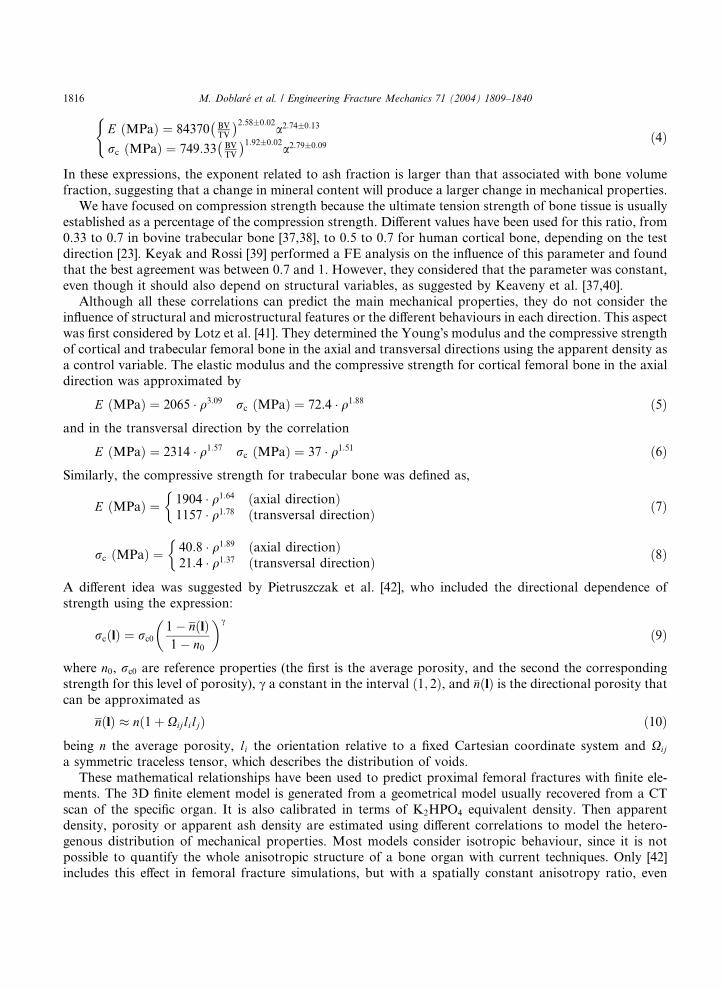
relatively well aligned with the principal material directions (see Fig. 5). This Tsai–Wu criterion has beenalso applied with varying degrees of success to cortical bone [135–137], and has been formulated in terms
of the fabric tensor [18], as will be shown below.
Cowin [18] proposed a fracture criterion useful for porous materials and/or composites, based on the
properties of the homogenized microstructure. The fracture criterion is a function f of the stress state, the
porosity n and the fabric tensor A as follows:
f ðA; r; nÞ ¼ f ðQAQT;QrQT; nÞ ¼ 1; 8Q orthogonal tensor ð21Þ
Cowin [18] considers that a quadratic function obtains a good compromise between reliability and com-
putational cost, with the criterion expressed as
Gijrij þ Fijkmrijrkm ¼ 1 ð22Þ
where rij are the stress components and Gij, Fijkm functions of A, n.Eq. (22) may be simplified by working in the space of principal stresses and considering a symmetrical
criterion with respect to the principal axes. It then depends on only three constants Gii and six Fiikk of thematerial as follows:
Tsai–Wu failure criterion for general triaxial normal loading for an apparent density of 0.6 g/cc. (From [127] with permission).

M. Doblar�e et al. / Engineering Fracture Mechanics 71 (2004) 1809–1840 1823
G11r11 þ G22r22 þ G33r33 þ F1111r211 þ F2222r2
22 þ F3333r233 þ 2F1122r11r22 þ 2F1133r11r33
þ 2F2233r22r33 ¼ 1 ð23Þ
Cowin [18] gives some indications to determine the constants from the ultimate strengths of the material
in the different directions and orientations. Thus
Gii ¼1
rþi� 1
r�i
Fiiii ¼1
rþi r
�i
ð24Þ
Fiijj ¼1
2
1
rþi r
�i
þ 1
rþj r
�j� 1
2r2ij
!� gðAÞ ð25Þ
where rþi , r
�i , rij are the ultimate strengths in tension, compression and in shear, respectively, along each
direction and plane and gðAÞ is a function of the fabric tensor. The main innovation with respect to Tsai–
Wu is the assumption that the tensors Fijkm, Gij are functions of the porosity and the fabric tensor, that is,
of the properties of the homogenized microstructure of the material.
Although this criterion has been cited by several authors [42,138], it has not been used in computational
simulations due to the difficulty of determining all the parameters involved. Only Gomez et al. [131] cor-related the different directional parameters of the Cowin criterion with the apparent density and the fabric
tensor, that were obtained after simulating the anisotropic bone remodelling and computing the density and
fabric tensor distribution on femoral bone. The approach was used to predict hip fractures and the results
were in accordance with the experimental work of Yang et al. [53].
Pietruszczak formulated a theory to explain fractures in concrete [139]. It has also been applied to
frictional materials [140] and bone tissue [42], with behave differently in terms of tension and compression.
This criterion takes into account the stress state rij, the fabric tensor Aij and the porosity n that defines the
failure criterion:
F ¼ b1�r
gðhÞ � rc
!þ b2
�rgðhÞ � rc
!2
� b3
�þ Irc
�¼ 0 ð26Þ
where I ¼ �rii is the (negative) trace of the stress tensor (negative first stress invariant); �r ¼ sijsij2
� �1=2(re-
lated to the second stress invariant) being sij the stress deviatoric tensor, h ¼ sen�1ffiffiffi3
psijsjkskl=2�r3
� �=3
(related to the third stress invariant), b1, b2, b3 are adimensional material constants and rc the ultimate
uniaxial compression strength. The g function of the third invariant is expressed as
gðhÞ ¼ ðffiffiffiffiffiffiffiffiffiffiffi1þ b
p�
ffiffiffiffiffiffiffiffiffiffiffi1� b
pÞK
Kffiffiffiffiffiffiffiffiffiffiffi1þ b
p�
ffiffiffiffiffiffiffiffiffiffiffi1� b
pþ ð1� KÞ
ffiffiffiffiffiffiffiffiffiffiffiffiffiffiffiffiffiffiffiffiffiffiffiffiffiffi1þ b � sin 3h
p ð27Þ
with b a constant close to 1, K a material dependent constant that represents the ratio between the ultimatevalue of �r in compression and in tension. This criterion was used by Pietruszcak et al. [42] to determine the
risk of fracture in human femurs, simulating the fracture produced by a fall. G�omez et al. [131] obtained
similar results when they compared this criterion with Cowin�s criterion.Finally, we can observe that there is a lack of agreement between different studies. Several authors
[37,125] suggest that strain-based failure theories are better than stress-based ones, but others indicate the
opposite [39]. For example, Keyak and several collaborators [39,49,129] mostly use distortion energy
theories (Von Mises–Hencky or Tresca criterion) to represent femoral bone fracture. But Fenech and
Keaveny [123], prefer maximum normal strain criterion in their study of trabecular bovine bone for uni-axial tensile or compressive loading along the principal trabecular direction combined with torsional
loading about the same direction.
1824 M. Doblar�e et al. / Engineering Fracture Mechanics 71 (2004) 1809–1840
There may be several causes for this discrepancy. Most computational simulations do not differentiate
between cortical and trabecular bone (only in porosity), but their structure is completely different, which
could affect their failure mechanisms. Also, most of the criteria assume isotropic behaviour, which is un-
realistic. All this controversy suggests that we are still far from getting a mechanobiologically based failurecriterion for bone and that more experimental, analytical and simulation works should be performed in
order to determine the appropriate bone failure theory. Some of the available results on the simulation of
bone fractures according to the previously explained criteria are shown in Section 6.
6. Modelling traumatic and pathologic fractures
The importance and high cost of treating bone fractures has promoted the development of non-invasive
methods of assessing fracture risk and prevention. The methods usually involve radiographic techniques to
measure bone mineral density, such as dual-energy X-ray absorptiometry (DXA) or quantitative compu-
ted tomography (QCT) [56,141–147]. The methodology has been somewhat successful but it is still lim-
ited by a more precise estimation of fracture load and the identification of subjects with a high risk of
fracture. It does not take into account different loading conditions, the distribution of bone material within
the entire structure and the properties of the distributed bone material [148]. In order to solve some of
these limitations, FEA have been widely used to predict and prevent the occurrence of hip fractures[39,42,49,50,126,128,129,132,138,149–151]. FEA helps to identify the most probable fracture mecha-
nisms, the regions where the fracture initially appears and the forces and orientations needed to produce
them.
All these models have similarities and differences that must be analysed in order to perform a com-
parative analysis that highlights their main limitations and the ideal properties that should be verified in
future developments.
Lotz et al. [132] studied the stress distributions in the proximal femur during a one-legged stance and for
a fall to the lateral greater trochanter. In the first case, the peak stresses were in the subcapital region. Forthe simulated fall, the peak stresses appeared in the intertrochanteric region. Cheal et al. [138] studied the
fracture strength of the proximal femur with a lesion in the femoral neck due to a tumor. They considered
four loading conditions corresponding to level gait and stair climbing. Lotz et al. [151] also examined the
evolution of stress distribution in the proximal femur during the three phases of the gait cycle, but they did
not compute fracture loads. Ford et al. [126] analyzed the effect of internal/external rotations on femoral
strength for loading that represented impact from a fall onto the hip. Sabick and Goel [150] compared the
failure loads for a posterolateral impact on the greater trochanter with a fall onto the buttocks, but they did
not study other load directions. Keyak et al. [129] analysed the ability of finite element models to predict thefracture location and/or type for two different loading conditions: one similar to joint loading during single-
limb stance and one simulating impact from a fall (the same fall that was simulated by Lotz et al. [132]). In
the first condition, the FE models predicted that only cervical fractures occurred (72% agreement with
experimental results). In the second case they predicted trochanteric and cervical fractures, obtaining a 79%
agreement with laboratory tests. Keyak et al. [152] also determined the force directions associated with the
lowest fracture loads for two types of loading: one simulating the impact from a fall and the other cor-
responding to joint loading during daily activities (atraumatic condition). For the fall, the force direction
with lowest fracture load was an impact onto the greater trochanter at an angle of 60� or 70� respect to theshaft. For atraumatic loading, the lowest fracture load was determined in conditions very similar to
standing on one leg or climbing stairs.
Gomez et al. [131] reproduced the experimental work performed by Yang et al. [53] using FEA. A
computational simulation was developed to characterize the heterogenous structural distribution in the

Fig. 6. (a) Factor of risk to fracture in the case of iliopsoas contraction; (b) X-ray of neck fracture (From [53] with permission).
M. Doblar�e et al. / Engineering Fracture Mechanics 71 (2004) 1809–1840 1825
femur and determine porosity and anisotropic properties. They were able to use the Cowin criterion as a
function of the porosity and fabric tensor [18], obtaining promising results that will be below reviewed.
They examined hip fracture patterns due to two possible contractions: iliopsoas and gluteus medius
muscle, in order to obtain a risk factor that is defined by the ratio between the Cowin equivalent stress and
the considered ultimate stress.
In the case of psoas-iliac contraction, a high risk factor is obtained in the neck area (Figs. 6 and 7). Theresults obtained indicate that a neck fracture probably occurs since the risk factor is over the limit value 1 in
this area, in a similar way that happened in Yang�s experiments for which all the seven femurs supporting
this type of load broke along the neck zone.
They [131] also studied hip fracture patterns due to contractions of the gluteus medius muscle and were
able to predict different subtrochanteric or intertrochanteric fractures (Figs. 8 and 9). It appears that
subtrochanteric fracture (or fracture in region D) is the most probable, although neck and trochanteric
fracture can also occur. Similar results were obtained in the Yang�s tests [53], where three femurs suffered
intertrochanteric fracture and four of them were subtrochanteric.
7. Bone fracture healing
Bone is a living material that is routinely exposed to mechanical environments that challenge its
structural integrity. As explained above, there are several causes of bone fractures. However, in contrast
with inert materials, bone can regenerate to form new osseous tissue where it is damaged or missing. In fact,
the healing of a fracture is one of the most remarkable of all the biological processes in the body.Understanding tissue regeneration is also essential to explain similar biological processes such as skeletal
embriogenesis and growth.
Bone ossification in the embryo and the growing child can occur in different forms: endochondral, in-
tramembranous or appositional ossification. In the first, cartilage is formed, calcified and replaced by bone.

Fig. 7. (a) Regions of proximal femur; (b) volume percentage of factor of risk for different femoral regions in the case of iliopsoas
contraction.
Fig. 8. (a) Factor of risk to fracture due to contractions of the gluteus medius muscle; (b) X-ray of intertrochanteric fracture (From [53]
with permission).
1826 M. Doblar�e et al. / Engineering Fracture Mechanics 71 (2004) 1809–1840

Fig. 9. Factor of risk in different regions in the case of gluteus medium contraction.
M. Doblar�e et al. / Engineering Fracture Mechanics 71 (2004) 1809–1840 1827
In the second, bone is formed directly by osteoblasts (flat bones like skull or pelvis). In the third, ossifi-
cation is adjacent to membrane layers of mesenchymal cells that differentiate into osteoblasts. Whenosteoblasts are not part of a membrane (i.e., endosteal, trabecular or Haversian canal surface) ossification
is called appositional. The last type of ossification is normally the only one found in healthy adults but
the two types can be activated during the fracture healing process. Therefore, this process is important to
understand tissue repair as well as tissue generation.
Fracture healing is a natural process that can reconstitute injured tissue and recover its original function
and form. It is a very complex process that involves the coordinated participation of immigration, differ-
entiation and proliferation of inflammatory cells, angioblasts, fibroblasts, chondroblasts and osteoblasts
which synthesize and release bioactive substances of extracellular matrix components (e.g., different typesof collagen and growth factors).
We can differentiate between primary or secondary fracture healing. Primary healing occurs in cases of
extreme stability and negligible gap size, involving a direct attempt by the bone to form itself directly [153].
Secondary healing occurs when there is not enough stabilisation and gap size is moderate. In this case,
healing activates responses within the periosteum and external soft tissues that form an external callus,
which reduces the initial movement by increasing stiffness. Most fractures are repaired by secondary
healing, which does a more thorough job of replacing old and damaged bone.
Secondary fracture healing has a series of sequential stages than can overlap to a certain extent, in-cluding inflammation, callus differentiation, ossification and remodelling.
The first stage begins after bone fracture. Blood emanates from the ruptured vessels and a hemorrhage
quickly fills the fracture gap space. Macrophages remove the dead tissue and generate initial granulation
tissue for the migration of undifferentiated mesenchymal cells, originating an initial stabilizing callus. These
cells proliferate and migrate from the surrounding soft tissue [153–156].
In the next stage, mesenchymal cells may differentiate into chondrocytes, osteoblasts or fibroblasts (Fig.
10), depending on the biological and mechanical conditions. These differentiated cells begin to synthesize
the extracellular matrix of their corresponding tissue. Intramembranous woven bone is produced by directdifferentiation of the stem cells into osteoblasts and appears adjacent to each side of the gap site, advancing
to the center of the callus. At the same time, at the center of the callus, cartilage is formed by chondro-
genesis, except right beside the gap where the stability is still very small and high relative displacement
prevents the differentiation of mesenchymal cells (Fig. 11).
Once the callus is filled (mainly by cartilage), endochondral ossification begins following a complex
sequence of cellular events including cartilage maturation and degradation, vascularity and osteogenesis.

Fig. 10. The mesengenic process (From [157] with permission).
Fig. 11. Callus at day 9 after fracture showing more mature bone under the periosteum (intramembranous ossification) and an
abundance of chondroid tissue adjacent to the fracture site (chondrogenesis) (From [153] with permission).
1828 M. Doblar�e et al. / Engineering Fracture Mechanics 71 (2004) 1809–1840
The ossification continues until all the cartilage has been replaced by bone and a bony bridge surrounds the
fracture gap, achieving a good stabilization and sufficient stiffness. When the fracture is completely sta-
bilized, mesenchymal cells begin to invade the gap (Fig. 11). Once the gap has ossified, remodelling of the
fracture site begins gradually in order to restore the original internal structure and shape (internal and

Fig. 12. Pauwels� concept of tissue differentiation (From [158] with permission).
M. Doblar�e et al. / Engineering Fracture Mechanics 71 (2004) 1809–1840 1829
external bone remodelling). The last stage is much longer than the previous one (1 year compared to several
weeks, depending on the animal species).
This summarizes the most important stages of bone fracture healing, although the evolution depends on
many factors such as mechanical, type of fracture, gap size, blood supply, hormones, growth factors, etc.
Fracture healing is an important topic of research in biomechanics. During the last years, many theories
and simulation models have been proposed to develop a comprehensive view of the mechanisms that
control bone morphogenesis. Pauwels [158] was one of the first authors to propose a theory of tissue
differentiation in response to local mechanical stress and strain (Fig. 12). He assumed that deviatoricstresses are the specific stimulus for the formation of fibrous connective tissue or bone, whereas hydrostatic
stresses control the formation of cartilaginous tissue.
Perren and Cordey [159,160] proposed that tissue differentiation is controlled by the resistance of various
tissues to strain. Their main idea is that a tissue that ruptures or fails at a certain strain level cannot
be formed in a region experiencing strains greater than this level. This theory is normally know as ‘‘the
interfragmentary strain theory’’ [161].
Carter et al. [162,163] developed a new tissue differentiation theory, which correlates new tissue for-
mation with the local stress/strain history. They described qualitatively the relationship between the ossi-fication pattern and the loading history, using finite elements to quantify the local stress/strain level,
assuming that the tissue in the callus is formed by a single solid phase. They proposed several interesting
differentiation rules that are graphically summarized in Fig. 13. In this figure there are two lines that
separate the different tissue regions. On the contrary, to the left of the pressure line, the tissue is supporting
a high hydrostatic pressure, which serves as stimulus for the production of cartilaginous matrix, to the right

Fig. 13. Relationship between mechanical stimuli and tissue differentiation (From [162] with permission).
1830 M. Doblar�e et al. / Engineering Fracture Mechanics 71 (2004) 1809–1840
of this line the hydrostatic pressure is very low, causing the production of bone matrix. There is a limit from
which this tissue is not differentiated, this one is limited by the boundary line of the right. When the tissue is
subjected to high tensile strains (above the tension line) fibrous matrix is produced with cartilage or bone
depending on the hydrostatic pressure level.
Many authors have also used computational models (mainly based on finite elements), to estimate local
strains and stresses during the different stages of fracture healing [161–163,165–168], since there is experi-
mental evidence [156,169] that tissue differentiation is mechanically dependent.Kuiper et al. [170–172] developed a differentiation tissue theory using the tissue shear strain and fluid
shear stress as the mechanical stimuli regulating tissue differentiation and the strain energy as the me-
chanical stimulus regulating bone resorption. They used an axisymmetric biphasic model of finite elements
of a fracture and applied movements on the cortical bone in an attempt to predict typical healing patterns
including callus growth. The results were that larger movements increased callus size and delayed bone
healing.
Lacroix et al. [161,173,174] used the differentiation rules proposed by Prendergast et al. [175] (see Fig. 14)
in combination with FEA to predict different fracture healing patterns depending on the origin of thestem cells. The model can predict the callus resorption produced in the last stage of the fracture healing
process, but cannot predict callus growth during the initial reparative phase (assuming a determined callus
size).
Ament and Hofer [176] proposed a tissue regulation model based on a set of fuzzy logic rules derived
from medical experiments, using the strain energy density as the mechanical stimulus that controls the
process of cell differentiation.
Fig. 14. Tissue differentiation law based on mechanical strain and fluid flow (From [174] with permission).
M. Doblar�e et al. / Engineering Fracture Mechanics 71 (2004) 1809–1840 1831
Bailon-Plaza and Van der Meulen [177] studied the fracture healing process produced by growth factors.
They used the finite differences method to simulate the sequential tissue regulation and the different cellular
events, studying the evolution of the several cells that exists in the callus.
More recently, Garc�ıa et al. [178] developed a continuum mathematical model that simulates the processof tissue regulation and callus growth, taking into account different cellular events (i.e., mesenchymal cell
migration, mesenchymal cell, chondrocyte, fibroblast and osteoblast proliferation, differentiation and
dead), and matrix synthesis, degradation, damage, calcification and remodelling over time. They also
analysed the evolution of the main components that form the matrix of the different tissues (i.e., different
collagen types, proteoglycans, mineral and water) to determine mechanical properties and permeability
according to this composition.
In order to define all these processes, the fundamental variables were the number of cells N and the
concentration c of each cell type (independent variables), with subscripts �s�, �b�, �f� and �c� indicating stemcells, osteoblasts, fibroblasts and chondrocytes respectively. They used the second invariant of the devia-
toric strain tensor w as the mechanical stimulus that controls the differentiation process, which also depends
on location and time. The rate of change of the number of cells in a control volume V of tissue at a point is
defined via the continuity equation to take into account changes in concentration and boundary growth valong the surface normal:
1 In
osteob
_Ni ¼ociðx; tÞ
ot
�þ grad ðciÞvþ ciðx; tÞdivðvÞ
�V ð28Þ
where they assume that each term evolves differently for each cell type, influenced by mechanical condi-
tions. When no growth occurs, cell concentration only changes by proliferation, migration, differentiation
or cell death. However, stem cells proliferate so much that a saturation concentration csat can be reached.In that case, the boundary has to move to give space for the extra cells, which is described as
divðvÞ ¼0 if cs < csat�fproliferationðx;wÞ
csatif cs ¼ csat
(ð29Þ
ocsðx; tÞot
¼ fproliferationðcs; x;wÞ þ fmigrationðcs; xÞ � fdifferentiationðx;w; tmÞ ð30Þ
being tm the maturation time. Growth also occurs when cartilage cells (chondrocytes) swell. In that case, the
number of cells in the volume does not change, but their concentration decreases:
divðvÞ ¼ � 1
ccðx; tÞoccðx; tÞ
otð31Þ
1
ccðx; tÞ¼ ggrowthðx;w;tmÞ ð32Þ
During osteoblast and fibroblast differentiation we assume a constant volume. The evolution of number
of osteoblasts depends on whether intramembranous or endochondral ossification 1 is produced:
_Nb ¼hdifferentiationðw; tmÞ intramembranous ossification
hremodellingðwÞ endochondral ossification
�ð33Þ
intramembranous ossification osteoblasts appear directly by differentiation from stem cells, while in endochondral ossification
lasts appear as consequence of calcification of cartilage and replacement by bone.

1832 M. Doblar�e et al. / Engineering Fracture Mechanics 71 (2004) 1809–1840
The different functions fproliferation, fmigration, fdifferentiation, ggrowth, hdifferentiation and hremodelling have to be defined
according to specific physiological features [178]. The underlying assumption in this work is that the level
of mechanical deviatoric strains in different regions of the callus is the main factor determining differen-
tiation of mesenchymal cells and consequently the process of tissue regeneration. It is very interestingthat the hypothesis used by Garc�ıa et al. [178] agrees with the experimental work by Bishop et al. [179],
who concluded that deviatoric strains may stimulate ossification more than volumetric strains.
Garc�ıa et al. [178] also characterized the composition and density of the extracellular matrix, assuming
that composition is independent of density and the main components are water, minerals, ground sub-
stances and different types of collagen. With these hypotheses and assuming all tissues are isotropic and
linear elastic, they evaluated the mechanical properties of the tissues using the next mixture rule depending
on the proportion of each component pi:
E ðMPaÞ ¼ 20000pmi þ 430pcI þ 200pcII þ 100pcIII þ 0:7pgsm ¼ 0:33pmi þ 0:48pcoll þ 0:49pgs
�ð34Þ
However the mechanical properties in the lamellar bone are computed using the following structural rule
where each subscript means mi: mineral, cI: collagen type I, cII: collagen type II, cIII: collagen type III, gs:ground substance:
E ¼ 2014q2:5; m ¼ 0:2 if q6 1:2 g cm�3
E ¼ 1763q3:2; m ¼ 0:32 if qP 1:2 g cm�3
�ð35Þ
The rate of matrix production and degradation depends directly on the cell population, except for the
lamellar bone that is controlled by bone remodelling.
This model has been implemented in a finite element code Marc. It correctly predicts tissue differenti-
ation and callus shape during fracture healing and quantifies the regulatory role of mechanical influences.
For example, Fig. 15 summarizes the evolution of the bone cells predicted by the model (human tibia with a
2 mm fracture), after applying a typical pattern of fracture movement. The model also predicts the damage
that is generated in soft tissues during fracture healing, which allows the study of pathological conditions
such as non-unions.Although the model is a good predictor of qualitative tissue differentiation and callus growth, it still
involves many simplifications that must be improved in the future. One example is the combination of
mechanical and growth factors and the role of vascularisation [170–172,180] and macrophages [181].
Most of the models analyze the course of differentiation tissue from a known interfragmentary move-
ment, which seems to be the main stimuli under sufficient vascularity [167,170–172,182–184]. However, this
movement depends on the applied load and the stability of the fixation used in the treatment. The load
sharing mechanism between the fractured bone and stiffness of the fixation should also be considered. Most
fracture healing models only analyze fractures under compression, while there are some important situa-tions (distraction osteogenesis) where tension is the main acting load.
Anisotropy should also be included in computational models, distinguishing between woven (more
isotropic) and lamellar bone (more anisotropic).
From a purely numerical point of view, mesh evolution should also be treated correctly, including
remeshing, rezoning and smoothing approaches. More recently, meshless methods that are less sensitive,
such as natural elements, have been used on similar problems [185].
Several authors [122,186] have also remarked that computer models evaluate mechanical stimuli from a
macroscopic (homogenized) continuum level. However, physiological cellular mechanisms are not yet wellunderstood and it is not clear whether the continuum approach is completely valid.

Fig. 15. Bone cell population: (a) initial condition, (b) 8 days, (c) 2 weeks, (d) 4 weeks, (e) 6 weeks and (f) 8 weeks after fracture.
M. Doblar�e et al. / Engineering Fracture Mechanics 71 (2004) 1809–1840 1833
8. Conclusions
More and more departments of Continuum Mechanics are becoming involved in orthopaedic research,
especially in the analysis of mechanical behaviour of living tissues (bone, ligaments and tendons) and the
design of implants. Both areas require in depth understanding of the behaviour of bone as a structural
material, especially the mechanisms of bone failure under different loading conditions and how the
mechanical factors affect bone fracture treatment.
It is very important to develop clinical and research tools to assess bone failure and healing in order to
improve the treatment and diagnoses of skeletal diseases. At the same time this helps to unravel theinteraction between mechanical and biochemical regulatory pathways.
Many experiments on skeletal failure and repair have been performed in the last century that include a
range of factors (biological, mechanical, hormonal, sex, age, etc.). Despite this effort, there are still many
unanswered questions. Some of the challenges arise from the difficulty of performing in vivo experiments
and interpreting their results, which are very difficult to compare across species, ages, patients, geometries,
bones, loading conditions and so on. All these facts indicate the complexity of the biological problems and
have stimulated the development of computational models that can analyze the influence of all factors and
make predictions under different conditions. These models must also be validated with experimental work.However, in many cases the computational models cannot be validated directly because some mea-
surements cannot be performed in vivo. Despite this, indirect validations can be performed if the con-
clusions of the computer simulations are similar to the experimental or clinical results. Indeed, simulations

1834 M. Doblar�e et al. / Engineering Fracture Mechanics 71 (2004) 1809–1840
of fracture healing are one of the clearest examples of this situation since it is impossible to measure the
stress or strain level in each tissue during differentiation. But most computational works reviewed here has
been helpful to study the influence of mechanical factors in this complex process.
Despite the limitations of computer models (e.g., lack of validation and biological information) muchprogress has been made on a clinical level, for example:
• Many designs of joint replacement prostheses have been studied using finite element models, either by
the manufacturer or by university institutes [187].
• Automated patient-specific finite element models have been useful in the assessment of femur and spine
fracture risk [188].
• Well-constructed computer models of bones have been used to investigate the effects of regional differ-
ences in age-related bone loss under different loading conditions [188].
Nevertheless, it is very difficult to obtain quantitative conclusions from computer simulations because of
anthropometric and metabolical differences between patients and animal species. Thus, research groups
should make an effort to quantify the range of variability of physiological parameters between individuals
and animals species.
Moreover, most computational models make important simplifications, especially in terms of the
characterization of material and boundary/loading conditions. Many computer analyses proceed without a
precise determination of material behaviour. So, we believe that the critical task for biomechanics is todetermine constitutive laws for living tissues. In particular, biomechanical models can be most improved by
including time-dependent mechanical properties, damage and repair of living tissues. In this paper, we have
focused on comparing the current theories of bone fracture and healing, indicating the fundamental con-
siderations to take into account for future improvements.
In the near future, it will be important to focus research on the integration of simulations, experiments
and theoretical aspects [122].
Use of computational simulations for the parametric examination of factors that are difficult or im-
possible to examine experimentally will contribute to the advance of biomechanics, as other authors havealso indicated [187,189].
All these facts suggest that future research programs in bone biomechanics will probably use more
complex and realistic computer simulations to reduce animal experimentation and clinical trials, with
important economic benefits. Perhaps it will be possible to develop computer analysis as a methodology to
perform realistic preoperative mechanical analysis of musculoskeletal disruptions, their prevention and
clinical treatment.
References
[1] Cooper C, Melton LJ. Hip fractures in the elderly: a world-wide projection. Osteoporosis Int 1992;2:285–9.
[2] Weiner S, Wagner HD. The material bone: structure-mechanical function relations. Ann Rev Mater Sci 1998;28:271–98.
[3] Robinson RA, Elliot SR. The water content of bone. I. The mass of water, inorganic crystals, organic matrix, and ‘‘CO2 space’’
components in a unit volume of dog bone. J Bone Joint Surg 1957;39A:167–88.
[4] Martin RB. Porosity and specific surface of bone. CRC Critical Reviews in Biomedical Engineering, 1984.
[5] Lucchinetti E. Composite models of bone properties. In: Bone mechanics handbook, 2nd ed. Boca Raton, FL: CRC Press; 2001.
p. 12.1–19 [chapter 3].
[6] Ginebra MP, Planell JA, Onta~n�on M, Aparicio C. Structure and mechanical properties of cortical bone. In: Structural biological
materials. New York: Pergamon Press; 2000. p. 33–71 [chapter 3].
[7] Martin RB, Burr DB, Sharkey NA. Skeletal tissue mechanics. New York: Springer-Verlarg; 1998.
[8] Williams PL. Gray�s anatomy. 38th ed. Churchill Livingstone; 1995.
[9] Cowin SC. Bone poroelasticity. J Biomech 1999;32(3):217–38.

M. Doblar�e et al. / Engineering Fracture Mechanics 71 (2004) 1809–1840 1835
[10] Currey JD. Bones. Structure and mechanics. Princeton, NJ: Princeton University Press; 2002.
[11] Fridez P. Mod�elisation de l�adaptation osseuse externe. PhD thesis, In Physics Department, EPFL, Lausanne, 1996.
[12] Miller SC, Jee WSS. Bone lining cells. In: Bone, vol. 4. Boca Raton, FL: CRC Press; 1992. p. 1–19.
[13] Cowin SC, Moss-Salentijn L, Moss ML. Candidates for the mechanosensory system in bone. J Biomech Engng 1991;113(2):191–
7.
[14] Lanyon LE. Osteocytes, strain detection and bone modelling and remodeling. Calcified Tiss Int 1993;53:102–7.
[15] Burger EH. Experiments on cell mechanosensivity: bone cells as mechanical engineers. In: Bone mechanics handbook. Boca
Raton, FL: CRC Press; 2001 [chapter 28].
[16] Skerry TM, Bitensky L, Chayen J, Lanyon LE. Early strain-related changes in enzyme activity in osteocytes following bone
loading in vivo. J Bone Miner Res 1989;4(5):783–8.
[17] Frost HM. Bone remodeling dynamics. Springfield, IL: Charles C. Thomas; 1963.
[18] Cowin SC. Fabric dependence of an anisotropic strength criterion. Mech Mater 1986;5:251–60.
[19] Odgaard A, Jensen EB, Gundersen HJG. Estimation of structural anisotropy based on volume orientation. A new concept.
J Microscopy 1990;157:149–82.
[20] Whitehouse WJ. The quantitative morphology of anisotropic trabecular bone. J Microscopy 1974;101:153–68.
[21] Whitehouse WJ, Dyson ED. Scanning electron microscope studies of trabecular bone in the proximal end of the human femur.
J Anatomy 1974;118:417–44.
[22] Odgaard A. Quantification of cancellous bone architecture. In: Bone mechanics handbook, 2nd ed. Boca Raton, FL: CRC Press;
2001. p. 14.1–14.19 [chapter 3].
[23] Reilly DT, Burstein AH. The elastic and ultimate properties of compact bone tissue. J Biomech 1975;8:393–405.
[24] Carter DR, Hayes WC. The compressive behavior of bone as a two-phase porous structure. J Bone Joint Surg 1977;59A:954–62.
[25] Carter DR, Spengler DR. Mechanical properties and composition of cortical bone. Clin Orthop Rel Res 1978;135:192–217.
[26] Gibson LJ. The mechanical behaviour of cancellous bone. J Biomech 1985;18:317–28.
[27] Goldstein SA. The mechanical properties of trabecular bone: dependence on anatomic location and function. J Biomech
1987;20:1055–61.
[28] Rice JC, Cowin SC, Bowman JA. On the dependence of the elasticity and strength of cancellous bone on apparent density.
J Biomech 1988;21:155–68.
[29] Martin RB. Determinants of the mechanical properties of bones. J Biomech 1991;24(S1):79–88.
[30] Vose GP, Kubala AL. Bone strength––its relationship to X-ray-determined ash content. Human Biol 1959;31:261–70.
[31] Currey JD. The mechanical consequences of variation in the mineral content of bone. J Biomech 1969;2:1–11.
[32] Currey JD. The effect of porosity and mineral content on the Young�s modulus of elasticity of compact bone. J Biomech
1988;21:131–9.
[33] Schaffler MB, Burr DB. Stiffness of compact bone: effects of porosity and density. J Biomech 1988;21:13–6.
[34] Keller TS. Predicting the compressive mechanical behavior of bone. J Biomech 1994;27:1159–68.
[35] Keyak JH, Lee I, Skinner HB. Correlations between orthogonal mechanical properties and density of trabecular bone: use of
different densitometric measures. J Biomech Mater Res 1994;28:1329–36.
[36] Hern�andez CJ, Beaupr�e GS, Keller TS, Carter DR. The influence of bone volume fraction and ash fraction on bone strength
and modulus. Bone 2001;29(1):74–8.
[37] Keaveny TM, Wachtel EF, Ford CM, Hayes WC. Differences between the tensile and compressive strengths of bovine tibial
trabecular bone depend on modulus. J Biomech 1994;27:1137–46.
[38] Stone JL, Beaupr�e GS, Hayes WC. Multiaxial strength characteristics of trabecular bone. J Biomech 1983;9:743–52.
[39] Keyak JH, Rossi SA. Prediction of femoral fracture load using finite elements models: an examination of stress- and strain-based
failure theories. J Biomech 1983;33:209–14.
[40] Keaveny TM. Strength of trabecular bone. In: Bone mechanics handbook. Boca Raton, FL: CRC Press; 2001 [chapter 16].
[41] Lotz JC, Gerhart TN, Hayes WC. Mechanical properties of metaphyseal bone in the proximal femur. J Biomech 1991;24:317–29.
[42] Pietruszczak S, Inglis D, Pande GN. A fabric-dependent fracture criterion for bone. J Biomech 1999;32(10):1071–9.
[43] Wirtz DC, Schiffers N, Pandorf T, Radermacher K, Weichert D, Forst R. Critical evaluation of known bone material properties
to realize anisotropic Fe-simulation of the proximal femur. J Biomech 2000;33(10):1325–30.
[44] Doblar�e M, Garc�ıa JM. Anisotropic bone remodelling model based on a continuum damage–repair theory. J Biomech
2002;35(1):1–17.
[45] Doblar�e M, Garc�ıa JM. Application of an anisotropic bone-remodelling model based on a damage–repair theory to the analysis
of the proximal femur before and after total hip replacement. J Biomech 2001;34(9):1157–70.
[46] Jacobs CR, Simo JC, Beaupr�e GS, Carter DR. Adaptive bone remodeling incorporating simultaneous density and anisotropy
considerations. J Biomech 1997;30(6):603–13.
[47] Fernandes P, Rodrigues H, Jacobs CR. A model of bone adaptation using a global optimisation criterion based on the
trajectorial theory of wolff. Comput Methods Biomech Biomed Engng 1999;2(2):125–38.
[48] Bagge M. A model of bone adaptation as an optimization process. J Biomech 2000;33(11):1349–57.

1836 M. Doblar�e et al. / Engineering Fracture Mechanics 71 (2004) 1809–1840
[49] Keyak JH. Improved prediction of proximal femoral fracture load using nonlinear finite element models. Med Engng Phys
2001;23:165–73.
[50] Lotz JC, Cheal EJ, Hayes WC. Fracture prediction for the proximal femur using finite element models: Part II––Nonlinear
analysis. J Biomech Engng 1991;113:361–5.
[51] Sloan J, Holloway G. Fractured neck of femur: the cause of the fall. Injury 1981;13:230–2.
[52] Horiuchi T, Igarashi M, Karube S, Oda H, Tokuyama H, Huang T, et al. Spontaneous fractures of the hip in the elderly.
Orthopedics 1988;11(9):1277–80.
[53] Yang KH, Shen KL, Demetropoulos CK, King AI. The relationship between loading conditions and fracture patterns of the
proximal femur. J Biomech Engng 1996;118:575–8.
[54] Smith LD. Hip fractures. The role of muscle contraction on intrinsic force in the causation of fractures of femoral feck. J Bone
Joint Surg 1953;35A:367–83.
[55] Zioupos P, Currey JD. Changes in the stiffness, strength, and toughness of human cortical bone with age. J Biomech
1998;22(1):57–66.
[56] Lotz JC, Hayes WC. The use of quantitative computed tomography to estimate risk of fracture of the hip from falls. J Bone Joint
Surg 1990;72a:689–700.
[57] Burr DB, Forwood MR, Schaffler MB, Fyhrie DP, Martin RB, Turner CH. Bone microdamage and skeletal fragility in
osteoporotic and stress fractures. J Bone Miner Res 1997;12:6–15.
[58] Schaffler MB, Jepsen JJ. Fatigue and repair in bone. Int J Fatigue 2000;22:839–46.
[59] Lee TC, O�Brien FJ, Taylor D. The nature of fatigue damage in bone. Int J Fatigue 2000;22:847–53.
[60] Hsieh YF, Silva MJ. In vivo fatigue loading of the rat ulna induces both bone formation and resorption and leads to time-related
changes in bone mechanical properties and density. J Orthop Res 2002;22:764–71.
[61] Verbogt O, Gibson GJ, Schaffler MB. Loss of osteocyte integrity in association with microdamage and bone remodelling after
fatigue in vivo. J Bone Miner Res 2000;15:60–7.
[62] Muir P, Johnson KA, Ruaux-Mason CP. In vivo matrix microdamage in a naturally occurring canine fatigue fracture. Bone
1999;25:571–6.
[63] Bentolila V, Boyce TM, Fyhrie DP, Drumb R, Skerry TM, Schaffler MB. Intracortical remodeling in adult rat long bones after
fatigue loading. Bone 1998;23(3):275–81.
[64] Burr DB, Martin RB, Schaffler MB, Radin EL. Bone remodeling in response to in vivo fatigue microdamage. J Biomech
1985;18:189–200.
[65] Martin RB. Is all cortical bone remodelling initiated by microdamage? Bone 2002;30(19):8–13.
[66] Hazelwood SJ, Martin RB, Rashid MM, Rodrigo JJ. A mechanistic model for internal bone remodeling exhibits different
dynamic responses in disuse and overload? J Biomech 2001;34(3):299–308.
[67] Martin RB. Toward a unifying theory of bone remodelling. Bone 2000;26:1–6.
[68] Martin RB. A theory of fatigue damage accumulation and repair in cortical bone. J Orthop Res 1992;10:818–25.
[69] Prendergast PJ, Taylor D. Prediction of bone adaptation using damage accumulation. J Biomech 1994;27:1067–76.
[70] Martin RB, Burr DB. A hypothetical mechanism for the simulation of osteonal remodelling by fatigue damage. J Biomech
1982;15:137–9.
[71] Carter DR, Hayes WC. Compact bone fatigue damage: a microscopic examination. Clin Orthop 1977;127:265–74.
[72] Burr DB, Schaffler MB, Frederickson RG. Composition of the cement line and its possible mechanical role as a local interface in
human compact bone. J Biomech 1988;21:939–45.
[73] Katz JL. Composite material models for cortical bone. In: Mechanical properties of bone. New York: Americal Society of
Mechanical Engineers; 1981. p. 171–84.
[74] Crolet JM, Aoubiza B, Meunier A. Compact bone: numerical simulation of mechanical characteristics. J Biomech
1993;26(6):677–87.
[75] Carter DR, Hayes WC. Fatigue life of compact bone. I. Effects of stress amplitude, temperature and density. J Biomech
1976;9(1):27–34.
[76] Norman TL, Vashishth D, Burr DB. Fracture toughness of human bone under tension. J Biomech 1995;28(3):309–20.
[77] Guo XE, Liang LC, Goldstein SA. Micromechanics of osteonal cortical bone fracture. J Biomech Engng 1998;120:112–7.
[78] Martin RB, Burr DB. Structure function and adaptation of compact bone. New York: Raver Press; 1989.
[79] Corondan G, Haworth WL. A fractographic study of human long bone. J Biomech 1986;19(3):207–18.
[80] Prendergast PJ, Huiskes R. Microdamage and osteocyte-lacuna strain in bone: a microstructural finite element analysis. J
Biomech Engng 1996;118(2):240–6.
[81] Melvin JW, Evans FG. Crack propagation in bone. Biomaterials Symposium, Americal Society of Mechanical Engineers, 1973.
[82] Bonfield W, Datta PK. Fracture toughness of compact bone. J Biomech 1976;9(3):131–4.
[83] Alto A, Pope MH. On the fracture toughness of equine metacarpi. J Biomech 1979;12:415–21.
[84] Norman TL, Vashishth D, Burr DB. Effect of groove on bone fracture toughness. J Biomech 1992;25:1489–92.

M. Doblar�e et al. / Engineering Fracture Mechanics 71 (2004) 1809–1840 1837
[85] Behiri JC, Bonfield W. Fracture mechanics of bone––the effects of density, specimen thickness and crack velocity on longitudinal
fracture. J Biomech 1984;17:25–34.
[86] Moyle DD, Gavens AJ. Fracture properties of bovine tibial bone. J Biomech 1986;19(11):919–27.
[87] Wright TM, Hayes WC. Fracture mechanics parameters for compact bone––effects of density and specimen thickness. J Biomech
1977;10(7):419–30.
[88] Yeni YN, Norman TL. Fracture toughness of human femoral neck: effect of microstructure, composition and age. Bone
2000;26(5):499–504.
[89] Lakes RS, Nakamura S, Behiri JC. Fracture mechanics of bone with short cracks. J Biomech 1990;23:967–75.
[90] Advani SH, Lee TS, Martin RB. Analysis of crack arrest by cement lines in osteonal bone. In: Proc ASME Annual Winter
Meeting, vol. 3, 1987. p. 57–8.
[91] Grynpas MD, Bonfield W, Young RJ. Crack velocity and the fracture of bone. J Biomech 1978;11:473–9.
[92] Vashishth D, Norman TL, Burr DB. Mode I fracture toughness of human bone. Advances in bioengineering, vol. 20. New York:
BED, ASME, 1991. p. 361–4.
[93] Schaffler MB, Radin EL, Burr DB. Mechanical and morphological effects of strain rate on fatigue of compact bone. Bone
1989;10:207–14.
[94] Schaffler MB, Radin EL, Burr DB. Long-term fatigue behaviour of compact bone at low strain magnitude and rate. Bone
1990;11:321–6.
[95] Mammone JF, Hudson SM. Micromechanics of bone strength and fracture. J Biomech 1993;26:439–46.
[96] Lee TC. Detection and accumulation of microdamage in bone. PhD thesis, University of Dublin, 1997.
[97] Lakes RS, Saha S. Cement line motion in bone. Science 1979;204:501–3.
[98] Reilly GC. Observations of microdamage around osteocyte lacunae in bone. J Biomech 2000;33:1131–4.
[99] Choi K, Godstein SA. A comparison of the fatigue behaviour of human trabecular and cortical bone tissue. J Biomech
1992;25:1371–81.
[100] Choi K, Fyhrie DP, Schaffler MB. Failure mechanisms of compact bone in bending: a microstructural analysis. In: Trans 40th
Orthop Res Soc, 1994. p. 425.
[101] Zioupos P, Casinos A. Cumulative damage and the response of human bone in two-step loading fatigue. J Biomech
1998;31(9):825–33.
[102] Yeni YN, Fyhrie DP. Fatigue damage-fracture mechanics interaction in cortical bone. Bone 2002;30(3):509–14.
[103] Arthur Moore TL, Gibson LJ. Microdamage accumulation in bovine trabecular bone in uniaxial compression. J Biomech Engng
2002;124(1):63–71.
[104] Reilly GC, Currey JD. The effects of damage and microcracking on the impact strength of bone. J Biomech 2000;33:337–43.
[105] Taylor D. Fatigue of bone and bones: an analysis based on stressed volume. J Orthop Res 1998;16:163–9.
[106] Burr DB, Turner CH, Naick P, Forwood MR, Ambrosius W, Hasan MS, et al. Does microdamage accumulation affect the
mechanical properties of bone? J Biomech 1998;31:337–45.
[107] Martin RB, Stover SM, Gibson VA, Gibeling JC, Griffin LV. In vitro fatigue behaviour of the equine third: remodelling and
microcrack damage analysis. J Orthop Res 1996;14:794–801.
[108] Schaffler MB, Pitchford WC, Choi K, Riddle JM. Examination of compact bone microdamage using back-scattered electron
microscopy. Bone 1994;15:483–8.
[109] Carter DR, Caler WE. Cycle-dependent and time-dependent bone fracture with repeated loading. J Biomech Engng
1983;105:166–70.
[110] Carter DR, Caler WE. A cumulative damage model for bone fracture. J Orthop Res 1985;3:84–90.
[111] Vashishth D, Tanner KE, Bonfield W. Contribution, development and morphology of microcracking in cortical bone during
crack propagation. J Biomech 2000;33:1169–74.
[112] Taylor D, Prendergast PJ. A model for fatigue crack propagation and remodelling in compact bone. Proc Inst Mech Engng
1997;211(5):369–75.
[113] Zioupos P, Currey JD, Sedman AJ. An examination of the micromechanics of failure of bone and antler by acoustic emission
tests and laser scanning confocal microscopy. Med Engng Phys 1994;16(3):203–12.
[114] Taylor D, Lee TC. Measuring the shape and size of microcracks in bone. J Biomech 1998;31:1177–80.
[115] Taylor D, Prendergast PJ. Damage accumulation in compact bone: a fracture mechanics approach to estimate damage and repair
rates. Adv Bioeng BED 1995;13:337–8.
[116] Caler WE, Carter DR. Bone creep-fatigue damage accumulation. J Biomech 1989;22:625–35.
[117] Zioupos P, Wang TW, Currey JD. Experimental and theoretical quantification of the development of damage in fatigue tests of
bone and antler. J Biomech 1996;29:989–1002.
[118] Pattin CA, Caler WE, Carter DR. Cyclic mechanical property degradation during fatigue loading of cortical bone. J Biomech
1996;29(1):69–79.
[119] Davy DT, Jepsen KJ. Bone damage mechanics. In: Bone mechanics handbook, 2nd ed. Boca Raton, FL: CRC Press; 2001.
p. 18.1–18.125 [chapter 3].

1838 M. Doblar�e et al. / Engineering Fracture Mechanics 71 (2004) 1809–1840
[120] Martin RB. A mathematical model for fatigue damage repair and stress fracture osteonal bone. J Orthop Res 1995;13:309–16.
[121] Ramtani S, Zidi M. A theoretical model of the effect of continuum damage on a bone adaptation model. J Biomech
2001;34(4):471–9.
[122] van der Meulen MCH, Huiskes R. Why mechanobiology? A survey article. J Biomech 2002;35:401–14.
[123] Fenech CM, Keaveny TM. A cellullar solid criterion for predicting the axial-shear failure properties of bovine trabecular bone.
J Biomech Engng 1999;121:414–22.
[124] Fenech CM, Keaveny TM. Successful prediction of axial-shear failure properties of bovine trabecular bone using simple
mechanistic criteria. In: Transactions of the Orthopaedic Research Society, vol. 22, 1997. p. 38.
[125] Ford CM, Keaveny TM. The dependence of shear failure properties of trabecular bone on apparent density and trabecular
orientation. J Biomech 1996;29:1309–17.
[126] Ford CM, Keaveny TM, Hayes WC. The effect of impact direction on the structural capacity of the proximal femur during falls.
J Bone Miner Res 1996;11:377–83.
[127] Keaveny TM, Wachtel EF, Zadesky SP, Arramon YP. Application of the Tsai–Wu quadratic multiaxial failure criterion to
bovine trabecular bone. J Biomech Engng 1999;121(1):99–107.
[128] Keyak JH, Rossi SA, Jones KA, Skinner HB. Prediction of femoral fracture load using automated finite elements modeling.
J Biomech 1998;31:125–33.
[129] Keyak JH, Rossi SA, Jones KA, Les CM, Skinner HB. Prediction of fracture location in the proximal femur using finite element
models. Med Engng Phys 2001;23(9):657–64.
[130] Oden ZM, Selvitelly DM, Bouxsein ML. Effect of local density changes on the failure load of the proximal femur. J Orthop Res
1999;17(5):661–7.
[131] G�omez MJ, Garc�ıa JM, Doblar�e M. Prediction of bone femoral fractures by means of the finite element method: 2nd European
Conference on Computational Mechanics. Cracow (Poland), 2001 (Proceedings in CD-Rom).
[132] Lotz JC, Cheal EJ, Hayes WC. Fracture prediction for the proximal femur using finite element models: Part I––Linear analysis.
J Biomech Engng 1991;113:353–60.
[133] Shigley JE. Mechanical engineering design. New York: Raver Press; 1977.
[134] Tsai SW, Wu EM. A general theory of strength for anisotropic materials. J Compos Mater 1971;5:58–80.
[135] Hayes WC, Wright TM. An empirical strength theory for compact bone. Fracture 1977;3:1173–9.
[136] Cowin SC. On the strength anisotropy of bone and wood. J Appl Mech 1979;4:137–47.
[137] Cezayirlioglu H, Bahniuk E, Davy DT, Heiple KG. Anisotropic yield behaviour of bone under combined axial force and torque.
J Biomech 1985;18:61–9.
[138] Cheal EJ et al. Evaluation of finite element analysis for prediction of strength reduction due to metastatic lesions in femoral neck.
J Biomech 1993;26(3):251–64.
[139] Pietruszczak S, Jiang J, Mirza FA. An elastoplastic constitutive model for concrete. Int J Solids Struct 1988;24(7):705–22.
[140] Pietruszczak S. An inelastic behaviour of anisotropic frictional materials. Mech Cohesive Frictional Mater 1999;4:281–93.
[141] Cummings SR, Black DM, Nevitt MC, Browner W, Cauley J, Ensrud K, et al. Bone density at various sites for prediction of hip
fractures. Lancet 1993;341:72–5.
[142] Gluer CC, Cummings SR, Pressman A, Li J, Gluer K, Faulkner KG, et al. Prediction of hip fractures from pelvic radiographs:
the study of osteoporotic fractures. The study of osteoporotic fractures research group. J Bone Miner Res 1994;9(5):671–7.
[143] Melton LJ, Wahner HW, Richelson LS, O�Fallon WM, Riggs BL. Osteoporosis and the risk of hip fracture. Am J Epidemiol
1986;124(2):254–61.
[144] Perloff JJ, McDermott MT, Perloff KG, Blue PW, Enzenhauer R, Sieck E, et al. Reduced bone-mineral content is a risk factor
for hip fractures. Orthop Rev 1991;20:690–8.
[145] Beck TJ, Ruff CB, Warden KE, Scott WW, Rao GU. Predicting femoral neck strength from bone mineral data. A structural
approach. Invest Radiol 1990;25:6–18.
[146] Esses SI, Lotz JC, Hayes WC. Biomechanical properties of the proximal femur determined in vitro by single-energy quantitative
computed tomography. J Bone Miner Res 1989;4:715–22.
[147] Lang P, Steiger P, Faulkner K, Gluer C, Genant HK. Osteoporosis. Current techniques and recent developments in quantitative
bone densitometry. Radiol Clin North Am 1997;29:49–76.
[148] Cody DD, Gross GJ, Hou FJ, Spencer HJ, Goldstein SA, Pyhrie DP. Femoral strength is better predicted by finite element
models than QCT and DXA. J Biomech 1999;32:1013–20.
[149] Keyak JH. Relationships between femoral fracture loads for two load configurations. J Biomech 2000;33(4):499–502.
[150] Sabick MS, Goel VK. Force needed to fracture and location of fracture region for two simulated fall positions. Trans Orthop Res
Soc 1997;22:833.
[151] Lotz JC, Cheal EJ, Hayes WC. Stress distributions within the proximal femur during gait and falls: implications for osteoporotic
fracture. Osteoporos Int 1995;5:252–61.
[152] Keyak JH, Skinner HB, Fleming JA. Effect of force direction on femoral fracture load for two types of loading conditions.
J Orthop Res 2001;19:539–44.

M. Doblar�e et al. / Engineering Fracture Mechanics 71 (2004) 1809–1840 1839
[153] Einhorn TA. The cell and molecular biology of fracture healing. Clin Orthop Rel Res 1998;355:S7–S21.
[154] McKibbin B. The biology of fracture healing in long bones. J Bone Joint Surg 1978;60B(2):150–62.
[155] Iwaki A, Jingushi S, Oda Y, Izumi T, Shida JI, Tsuneyoshi M, et al. Localization and quantification of proliferating cells during
rat fracture repair: detection of proliferating cell nuclear antigen by immunochemistry. J Bone Miner Res 1997;12:96–102.
[156] Sandberg MM, Aro HT, Vuorio EI. Gene expression during bone repair. Clin Orthop Rel Res 1993.
[157] Caplan AI, Boyan BD. Endochondral bone formation: the lineage cascade. In: Mechanism of bone development and growth.
Boca Raton, FL: CRC Press; 1994.
[158] Pauwels F. Eine neue theorie €uber den einflub mechanischer reize auf die differenzierung der st€utzgewebe. Z Anat
Entwicklungsgeschichte 1960;121:478–515.
[159] Perren SM. Physical and biological aspects of fracture healing with special reference to internal fixation. Clin Orthop Rel Res
1979;138:175–96.
[160] Perren SM, Cordey J. The concept of interfragmentary strain. In: Current concepts of internal fixation of fractures. Berlin:
Springer-Verlarg; 1980. p. 63–77.
[161] Lacroix D. Simulation of tissue differentiation during fracture healing. PhD thesis, University of Dublin, 2000.
[162] Carter DR, Beaupr�e GS, Giori NJ, Helms JA. Mechanobiology of skeletal regeneration. Clin Orthop Rel Res 1998;S355:S41–55.
[163] Carter DR, Blenman PR, Beaupr�e GS. Correlations between mechanical stress history and tissue differentiation in initial fracture
healing. J Orthop Res 1988;6:736–48.
[164] Hoffman O. The brittle strength of orthotropic materials. J Compos Mater 1967;1:200.
[165] Blenman PR, Carter DR, Beaupr�e GS. Role of mechanical loading in the progressive ossification of a fracture callus. J Orthop
Res 1989;7:398–407.
[166] Cheal EJ, Mansmann KA, DiGioia AM, Hayes WC, Perren SM. Role of interfragmentary strain in fracture healing: ovine model
of a healing osteotomy. J Orthop Res 1991;9:131–42.
[167] Claes LE, Heigele CA. Magnitudes of local stress and strain along bony surfaces predict the course and type of fracture healing.
J Biomech 1999;32:255–66.
[168] Gardner TN, Stoll T, Marks L, Mishra S, Knothe Tate M. The influence of mechanical stimulus on the pattern of tissue
differentiation in a long bone fracture-an FEM study. J Biomech 2000;33:415–25.
[169] Ashhurst DE. The influence of mechanical stability on the healing of experimental fractures in the rabbit: a microscopical study.
Series B 313 (1986) 271–302.
[170] Kuiper JH, Richardson JB, Ashton BA. Mechanical signals in early fracture callus. In: Vander Sloten J, Lowet G, Van
Audekercke R, Van der Perre G, editors. Proc 10th Europ Soc Biomech, 1996. p. 154.
[171] Kuiper JH, Ashton BA, Richardson JB. Computer simulation of fracture callus formation and stiffness restoration. In:
Prendergast PJ, Lee TC, Carr AJ, editors. Proc 12th Europ Soc Biomech, 2000. p. 61.
[172] Kuiper JH, Richardson JB, Ashton BA. Computer simulation to study the effect of fracture site movement on tissue formation
and fracture stiffness restoration. In: European Congress on Computational Methods in Applied Sciences and Engineering
ECCOMAS, 2000.
[173] Lacroix D, Prendergast PJ, Marsh D, Li G. Simulation of tissue differentiation during fracture healing. Trans Orthop Res Soc
2000;25:869.
[174] Lacroix D, Prendergast PJ. A mechano-regulation model for tissue differentiation during fracture healing: analysis of gap size
and loading. J Biomech 2002;35:1163–71.
[175] Prendergast PJ, Huiskes R, Soballe K. Biophysical stimuli on cells during tissue differentiation at implant interfaces. J Biomech
1997;6:539–48.
[176] Ament Ch, Hofer EP. A fuzzy logic model of fracture healing. J Biomech 2000;33:961–8.
[177] Bail�on-Plaza A, Van Der Meulen MCH. A mathematical framework to study the effects of growth factor influences on fracture
healing. J Theor Biol 2001;212:191–209.
[178] Garc�ıa JM, Kuiper JH, Doblar�e M, Richardson JB. A numerical model to study the mechanical influences on bone fracture
healing. Acta of Bioengineering and Biomechanics, 4(S1), pp. 394–395, 2002 (Proceedings of the 13th Conference of European
Society of Biomechanics).
[179] Bishop NE, Tami I, Schneider E, Ito K. In vivo comparison of early fracture healing under deviatoric and volumetric
deformation. Acta Bioeng Biomech 2002;4(S1):754–5.
[180] Simon U, Augat P, Utz M, Claes L. Dynamical simulation of the fracture healing process including vascularity. Acta Bioeng
Biomech 2002;4(S1):772–3.
[181] Hankemeier S, Gr€assel S, Plenz G, Spiegel HU, Bruckner P, Probst A. Alteration of fracture stability influences chondrogenesis,
osteogenesis and immigration of macrophages. J Orthop Res 2001;19:531–8.
[182] Goodship AE, Kenwright J. The influence of induced micromovement upon the healing of experimental tibial fractures. J Bone
Joint Surg 1987;20:1055–61.
[183] Claes LE, Wilke HJ, Augat P, R€ubenacker S, Margevicius K. Effect of dynamization of gap healing of diaphyseal fractures under
external fixation. Clin Biomech 1995;8:227–34.
1840 M. Doblar�e et al. / Engineering Fracture Mechanics 71 (2004) 1809–1840
[184] Gardner TN, Evans M, Simpson H. Temporal variation of applied inter fragmentary displacement at a bone fracture in harmony
with maturation of the fracture callus. Med Engng Phys 1998;20:480–4.
[185] Doblar�e M, Cueto E, Cego~nino J, Garc�ıa JM. On the use of meshless methods in numerical biomechanical simulation. Acta
Bioeng Biomech 2002;4(S1):126–7.
[186] Humphrey JD. Stress, strain and mechanotransduction in cells. J Biomech Engng 2001;123:638–41.
[187] Prendergast PJ. Finite element models in tissue mechanics and orthopaedic implant design. Clin Biomech 1997;12(6):343–66.
[188] Villarraga ML, Ford CM. Applications of bone mechanics. In: Bone mechanics handbook. Boca Raton, FL: CRC Press; 2001
[chapter 33].
[189] Huiskes R. The law of adaptive bone remodelling: a case for crying Newton? In: Structure and remodelling. Singapore: Wold
Scientific; 1995. p. 15–24.
Related Documents