TALLINN UNIVERSITY OF TECHNOLOGY Faculty of Information Technology Department of Informatics Chair of Software Engineering Modelling and Simulation of Physical Environment for Training Scenarios in Crisis Management Master’s Thesis Student: Jishu Guin Student’s code: 113674 Supervisor: Professor Kuldar Taveter, PhD Tallinn 2014

Welcome message from author
This document is posted to help you gain knowledge. Please leave a comment to let me know what you think about it! Share it to your friends and learn new things together.
Transcript

TALLINN UNIVERSITY OF TECHNOLOGY
Faculty of Information Technology
Department of Informatics
Chair of Software Engineering
Modelling and Simulation of Physical Environment
for Training Scenarios in Crisis Management
Master’s Thesis
Student: Jishu Guin
Student’s code: 113674
Supervisor: Professor Kuldar Taveter, PhD
Tallinn
2014

Copyright Declaration
I hereby declare that this master’s thesis is my original investigation and achievement, and
it has not been previously submitted by anyone for the defence. All works, major
viewpoints, data taken from existing literature and elsewhere that were used for writing this
paper are referenced.
03.06.2014
(date) (signature)

Acknowledgement
I thank professor Kuldar Taveter for giving me the opportunity to take part in this work, through
which I have gained knowledge that I hope will be of great value in my future endeavours. His
support has been of great help and encouragement. I would like to thank professor Juri Vain for
the inspiration that he provided through his lectures and appreciation.
I thank the faculty at the Department of Computer Science for being of great help in building my
interests in various areas which I was able to consider for this work. I would like to thank Tallinn
University of Technology for access to various databases without which I could not have
completed this work. I am thankful to Marlon Dumas at the University of Tartu for extending his
support and advice, which helped me take decisions on various occasions during the curriculum.
I thank my family for their valuable support and encouragement.
Abstract
The thesis is based on a research done at Tallinn University of Technology, addressing the
development of an agent-oriented system for simulating training scenarios in urban operation. An
urban operation is defined as all operations planned and conducted across the range of military
operations on, or against objectives within, a terrain, where man-made construction and presence
of non-combatants are the dominant features. The research establishes that agent oriented
modelling has the potential to deal with the challenges posed by the dynamic nature of urban
environment in designing realistic scenarios for the simulation of urban operation. The research
proposes the development of realistic training scenarios in the direction of modelling human
behaviour using agent oriented behaviour models. In such training scenarios, a software agent can
be replaced by a real player. This thesis advances the work in that direction by implementing a
highly simplified exemplary scenario of urban operation using an existing agent based modelling
toolkit called Repast Simphony. The system simulates a simple building evacuation scenario.
Some key characteristics of the scenario are based on the urban operation scenario of the parent
work. The implementation is based on platform independent models developed by following the
viewpoint framework.
One of the main areas of focus in this simulation is the urban environment. The exemplary
scenario simulates a simplified building evacuation operation. The building environment is
modelled using a formal method for modelling indoor spaces, called Weighted Indoor Routing
Graph. The thesis also discusses two ontologies which support representation of city models -
IFC and CityGML, with the aim to consider using industry standard ontologies to model realistic
environments in agent based simulations. Based on a preliminary comparative study made on
these two ontologies, CityGML is found to be more suitable to model environment in an agent
based urban operation simulation.
The future enhancements to this work includes as a first immediate step to use a simple building
model in CityGML to create the environment of the prototype application developed for this
thesis, which will provide an insight into the technicalities of integrating an ontology with the
system. Further onwards, the work can lead to the development of realistic simulations for
training scenarios using CityGML models.

Glossary of the Abbreviations and Acronyms
AOM Agent Oriented Modelling
ABMS Agent Based Modelling and Simulation
AUML Agent Unified Modelling Language
CityGML City Geographic Markup Language
IFC Industry Foundation Classes
GIS Geographic Information System
GML Geography Markup Language

List of Figures
Figure 1. Goal Model ............................................................................................................... 12
Figure 2. Environment Model .................................................................................................. 13
Figure 3. Basic Agent ............................................................................................................... 17
Figure 4. Abstract agent architecture ........................................................................................ 18
Figure 5. Building evacuation goal model................................................................................ 22
Figure 6. Goal model for “Search for victim” .......................................................................... 23
Figure 7. Goal model for Evacuation ....................................................................................... 23
Figure 8. Organization model ................................................................................................... 25
Figure 9. Domain Model .......................................................................................................... 27
Figure 10. Acquaintance model ................................................................................................ 29
Figure 11. Interaction frame diagram ....................................................................................... 30
Figure 12. Interaction Protocol ................................................................................................. 31
Figure 13. Knowledge Model ................................................................................................... 33
Figure 14. Behaviour model ..................................................................................................... 39
Figure 15. GuardAgent execution cycle ................................................................................... 40
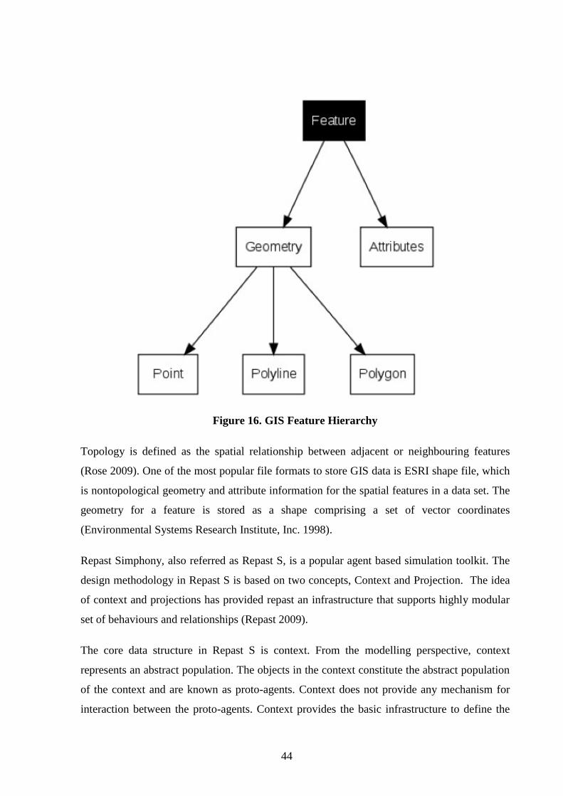
Figure 16. GIS Feature Hierarchy ............................................................................................ 44
Figure 17. Repast context hierarchy ......................................................................................... 45
Figure 18. Context with agents, projections and a sub-context ................................................ 46
Figure 19. Building Shapefile ................................................................................................... 47
Figure 20. Routing Graph ......................................................................................................... 48
Figure 21. Shapefile Edge attributes ........................................................................................ 49
Figure 22. Build Network ......................................................................................................... 50
Figure 22. Door block trigger ................................................................................................... 51
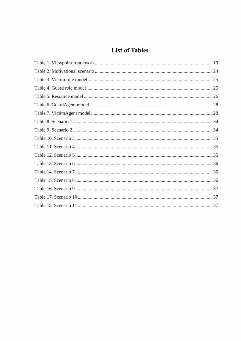
List of Tables
Table 1. Viewpoint framework ................................................................................................. 19
Table 2. Motivational scenario ................................................................................................. 24
Table 3. Victim role model ....................................................................................................... 25
Table 4. Guard role model ........................................................................................................ 25
Table 5. Resource model .......................................................................................................... 26
Table 6. GuardAgent model ..................................................................................................... 28
Table 7. VictimAgent model .................................................................................................... 28
Table 8. Scenario 1 ................................................................................................................... 34
Table 9. Scenario 2 ................................................................................................................... 34
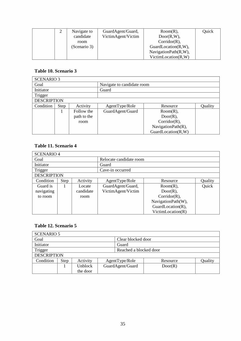
Table 10. Scenario 3 ................................................................................................................. 35
Table 11. Scenario 4 ................................................................................................................. 35
Table 12. Scenario 5 ................................................................................................................. 35
Table 13. Scenario 6 ................................................................................................................. 36
Table 14. Scenario 7 ................................................................................................................. 36
Table 15. Scenario 8 ................................................................................................................. 36
Table 16. Scenario 9 ................................................................................................................. 37
Table 17. Scenario 10 ............................................................................................................... 37
Table 18. Scenario 11 ............................................................................................................... 37
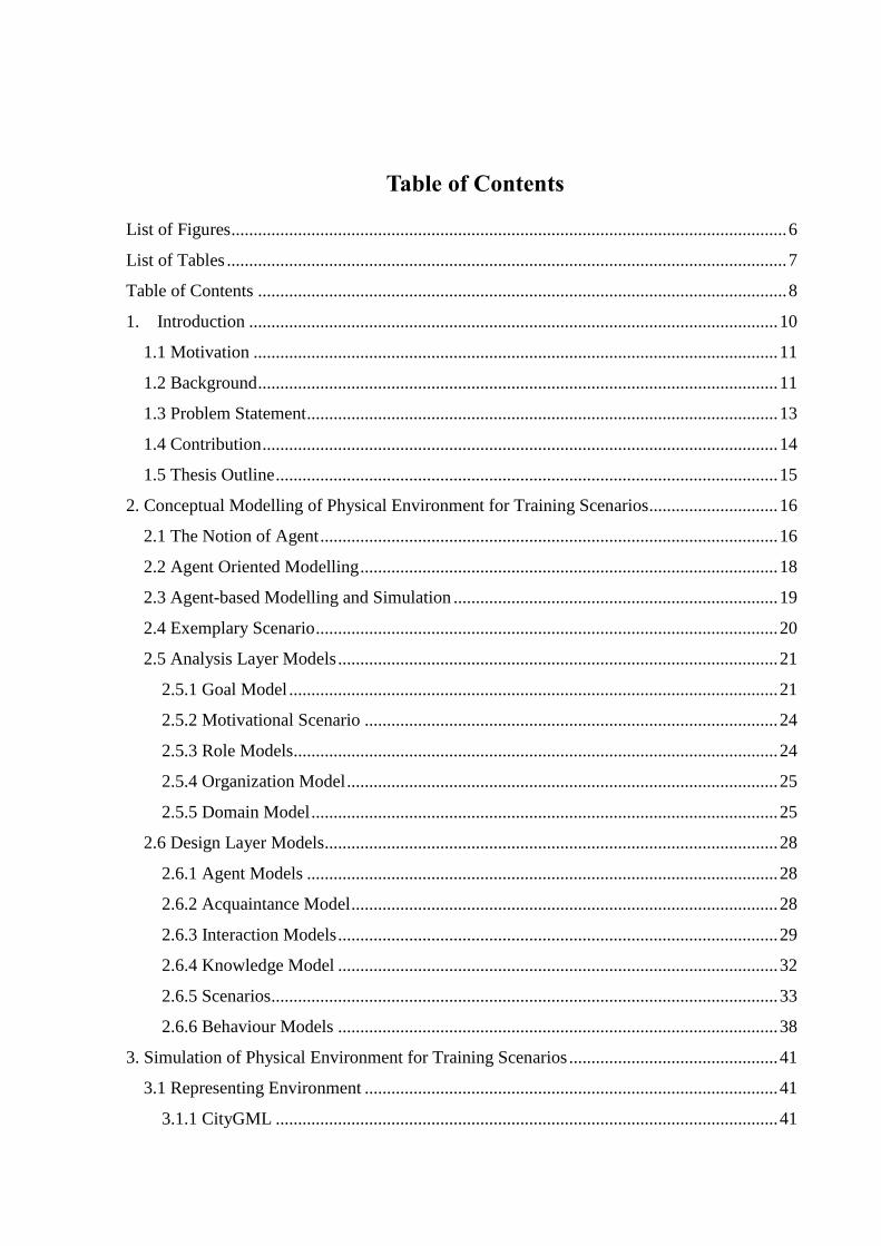
Table of Contents
List of Figures ............................................................................................................................. 6
List of Tables .............................................................................................................................. 7
Table of Contents ....................................................................................................................... 8
1. Introduction ....................................................................................................................... 10
1.1 Motivation ...................................................................................................................... 11
1.2 Background ..................................................................................................................... 11
1.3 Problem Statement .......................................................................................................... 13
1.4 Contribution .................................................................................................................... 14
1.5 Thesis Outline ................................................................................................................. 15
2. Conceptual Modelling of Physical Environment for Training Scenarios............................. 16
2.1 The Notion of Agent ....................................................................................................... 16
2.2 Agent Oriented Modelling .............................................................................................. 18
2.3 Agent-based Modelling and Simulation ......................................................................... 19
2.4 Exemplary Scenario ........................................................................................................ 20
2.5 Analysis Layer Models ................................................................................................... 21
2.5.1 Goal Model .............................................................................................................. 21
2.5.2 Motivational Scenario ............................................................................................. 24
2.5.3 Role Models ............................................................................................................. 24
2.5.4 Organization Model ................................................................................................. 25
2.5.5 Domain Model ......................................................................................................... 25
2.6 Design Layer Models...................................................................................................... 28
2.6.1 Agent Models .......................................................................................................... 28
2.6.2 Acquaintance Model ................................................................................................ 28
2.6.3 Interaction Models ................................................................................................... 29
2.6.4 Knowledge Model ................................................................................................... 32
2.6.5 Scenarios .................................................................................................................. 33
2.6.6 Behaviour Models ................................................................................................... 38
3. Simulation of Physical Environment for Training Scenarios ............................................... 41
3.1 Representing Environment ............................................................................................. 41
3.1.1 CityGML ................................................................................................................. 41

3.1.2 IFC ........................................................................................................................... 42
3.1.3 GIS and Repast Simphony ....................................................................................... 42
3.2 Simulation of Physical Environment by Repast Simphony............................................ 47
4. Conclusion ............................................................................................................................ 52
Resümee ................................................................................................................................... 54
References ................................................................................................................................ 56
10
1. Introduction
Social interaction in a population is an important factor that shapes the characteristics of both
an individual and the population due to the impact they have on each other. The effect of this
mutual interaction may range from symbiotic to catastrophic. In either case the prominence of
such outcomes pose a demand to understand and predict the dynamic behaviour of these
scenarios. The need to grasp the behaviour of real world dynamic scenarios accompanied by
the advancement of research in various fields, especially in the dynamics of social interaction
in a population, has increasingly motivated the development of numerous technologies to
model real world scenarios. Crisis is one such scenario that is of key importance because of its
obvious disastrous impact on society and individual life.
As defined from a management perspective, an organizational crisis is a low-probability,
high-impact event that threatens the viability of the organization and is characterized by
ambiguity of cause, effect, and means of resolution, as well as by a belief that decisions must
be made swiftly. Organizational crisis management is a systematic attempt by organizational
members with external stakeholders to avert crises or to effectively manage those that do
occur (Pearson 1998). The complexity of the dynamics of a crisis event makes crisis
simulation a reasonable and popular method for the study of crisis scenarios and provide
training environment for crisis management.
The crisis environment is a real world environment with various autonomous entities e.g.
Victims, Rescuers, Animals, Robots, etc. The interaction between these entities, or agents in
terms of Agent Oriented Modelling paradigm, is complex and important from the perspective
of the dynamics of a crisis event. This structure of a crisis environment makes AOM a
suitable methodology for crisis simulation. Agent based simulation of crisis management is a
progressive and active field of research (Quillinan 2009).
The work presented in this thesis is based the research done by Shvartsman et al.
(Shvartsman 2010), where an agent based simulation is modelled for training scenarios in
urban operation. A proposal made in the research is the development of realistic training
scenarios in the direction of modelling human behaviour. Such training simulation can replace
a software agent by a human player. The benefit of this approach is its usability to observe
11
how real subjects for their decision to behave in certain situation. One of the key elements of
such training scenarios is the environment of the simulation. The simulated environment
includes the model of the physical environment for the training. The environment in a crisis
scenario is of critical importance as it is one of the prominent factors driving the interactions
and behaviour of the agents situated in it. The environment of a simulation plays a key role in
determining the accuracy of the simulation compared to real scenarios. This poses a demand
on the simulation environment to be as realistic as possible to the real physical terrain of the
urban operation. In this thesis we take a preliminary step towards realizing this demand and
thereby making way to accomplish the vision of the background work.
1.1 Motivation
The uncertainties of a crisis situation pose a challenge to create realistic training scenarios for
urban operations. It is difficult to train a person for something that is not defined. It is possible
to explore human behaviour with training scenarios where human players can replace
software agents. This knowledge about human behaviour can be useful to create
computational models of interactive human behaviour, thereby helping to simulate complex
socio-technical systems.
The ability to create realistic training scenarios has various beneficial implications, especially
in crisis management. Simulating the physical environment is an important part of the training
scenario. The work in this thesis is a small but significant step to assist this cause.
1.2 Background
The term crisis management primarily refers to any disaster management in an urban
environment in the context of this thesis. The environment mostly includes man-made urban
structures like buildings and roads. The urban operation modelled in the original research is to
rescue victims from inside buildings.
This agent-based system aims to simulate a training environment to train professionals in the
rescue operation. The role of the professional can be played either by human or a software
agent. There are different roles that coordinate with each other. The simulation allows altering
the attributes of the agent to simulate a different personality of the rescuer based on certain
criteria. This is a useful feature, which gives an insight into two important aspects. First, it
12
helps us understand how a particular profile performs in a role. Second, it gives a metric of
the overall performance of the operation with a particular set of profiles for different roles.
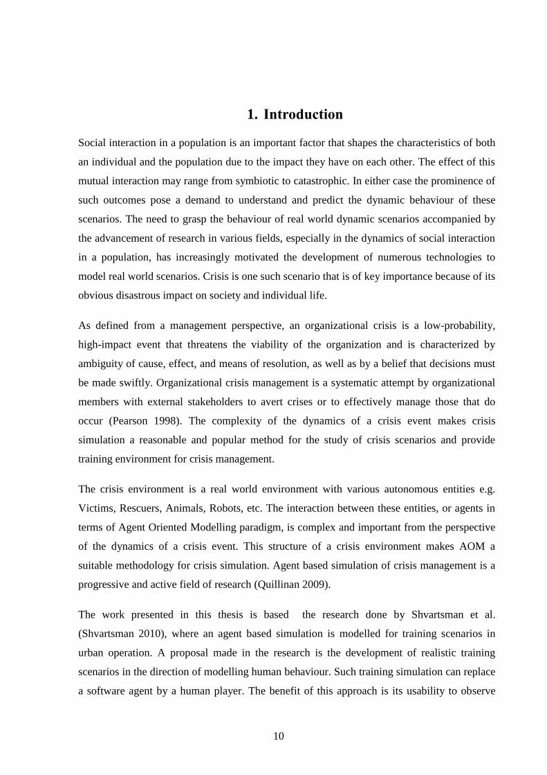
The system follows the Agent oriented modelling paradigm, which is explained in more
details in the subsequent sections of the thesis. The AOM paradigm is compliant with the
Model Driven Architecture, thus, it uses various models (as shown in Figure 1 and Figure 2)
at different layers of abstraction. These platform independent abstract models provide the
premise for a platform dependent implementation of the agent oriented simulation.
Figure 1. Goal Model
In this thesis a small exemplary scenario of urban operation is developed on an agent based
platform. The selection of the agent-based platform was made as a background work. Three
popular platforms – Madkit, Repast Simphony and Mason, were surveyed and a high level
comparative study was made on them based on their features and the application architecture
supported. These three platforms were selected based on the following criteria, which they all
satisfy:
Freeware
Open source
Deployable
Java based

13
Experience of research group.
Figure 2. Environment Model
The preliminary study on the platforms selected Repast Simphony as the most suitable one for
developing the exemplary scenario. The primary reason for the selection of repast is the direct
support it provides for context awareness, which is an important concept in the context-aware
crisis management, where the context has an impact on the behaviour and interactions of the
agent. Repast symphony provides platform support for the concept of context, which is
significant from the environment perspective. The later sections of the thesis will provide
more details about the platform.
1.3 Problem Statement
The aim of the urban operation simulation is to provide training scenarios in which both
human and software agents can participate. The quality of the training scenario depends on

14
how realistic the system can simulate the dynamics of a real urban operation environment.
The realistic nature of the simulation environment is not only in terms of the semantic
knowledge it provides but also from a visual aspect. The environment more than any other
factor, strongly influences combat identification (e.g., cognitive processes, situational
awareness, and visual discrimination), movement and capabilities of (the system of) the
contending parties (Shvartsman 2010).
The original research identified the difficulties in realistic training in urban operations due to
their asymmetric nature. The work in Shvartsman et al. (Shvartsman 2010) proposes the
development of realistic training scenarios to model human behaviour. The use of agent
oriented modelling is suggested to explore human behaviour using these training scenarios.
The development of training scenarios would require simulation of realistic scenarios of urban
operations. Simulation of an urban operation involves simulation of a complex environment,
of which, the physical environment is an important part. The development of a realistic urban
operation scenario is difficult because of the large scope and complexity of the domain, but
never the less important. The thesis is a step towards addressing this specific problem.
1.4 Contribution
The contribution of the author in this thesis addresses the problem in two parts. The first part
targets the scope and complexity of the scenario by implements a highly simplified version of
an urban operation scenario on an agent based simulation platform called Repast Simphony.
The simplicity of the simulation reduces the scope for the initial development. The prototype
models a building evacuation scenario with a simple visual environment using “Shapefiles”.
Shapefile is a standard format to represent geo-spatial environment data. The system is
developed following the viewpoint framework for agent oriented modelling. Agent oriented
modelling was chosen to address the complexity of the simulation in terms of the interaction,
information and behaviour aspects.
One of the requirements for the simulation is that it should be realistic. Shapefiles can capture
the geospatial layout of geographical terrains, based on the location of objects. However, they
do not support any semantic structure of urban environments. The realistic expectation from
visual environments in simulation of urban scenario demands more advanced means of
capturing the environment knowledge. A preliminary comparative study is made on two
15
industry standards, which support representation of urban environments - IFC and CityGML
to find a suitable alternative to “Shapefiles” to be used for the simulation in future.
1.5 Thesis Outline
The contents of the thesis further onwards are presented as three main sections – Section two
three and four. The first describes the modelling of the physical environment for the training
scenarios. It has two parts – the first part provides some required background theory about
AOM paradigm and the second part presents the various platform independent models for a
simulation system for building evacuation. The next section presents the platform dependent
aspects captured in the implementation of the system in Repast Simphony. It has again two
parts. The first part introduces two advanced industry standards for representing environment
– IFC and CityGML. It also describes a well-known basic format to capture geo spatial
information – Shapefiles and its support in a popular agent based simulation platform –
Repast Simphony. The section ends with the description of the implementation of physical
environment for the building evacuation simulation developed in Repast using Shapefiles.
The final section provides the conclusion of the work with proposals for future enhancements.

16
2. Conceptual Modelling of Physical Environment for Training
Scenarios
This chapter presents the various steps into modelling the exemplary scenario for the
simulation of a building evacuation operation. The simulation is motivated by the urban
operation scenario presented in Shvartsman et al. (Shvartsman 2010). The modelling
paradigm used is the agent oriented modelling as described in Sterling et al. (Sterling 2009).
The subsequent sections of the chapter briefly describe the concepts related to the AOM
paradigm followed by the various models of to capture a complete platform independent view
of the system.
2.1 The Notion of Agent
Agent based modelling and simulation is an approach to modelling systems comprising of
autonomous interacting agents (Castle 2006). ABMS approach has become popular for
modelling and simulation of real world scenarios. Real world scenarios are complex from the
aspect of the number of entities involved and the autonomous behaviour of those entities.
ABMS provides a way to capture the complexity and bring an order to the apparent chaos by
providing a model of the system. The model enables us to control certain parameters of the
system to observe and study the effects, which makes this paradigm suitable for simulation.
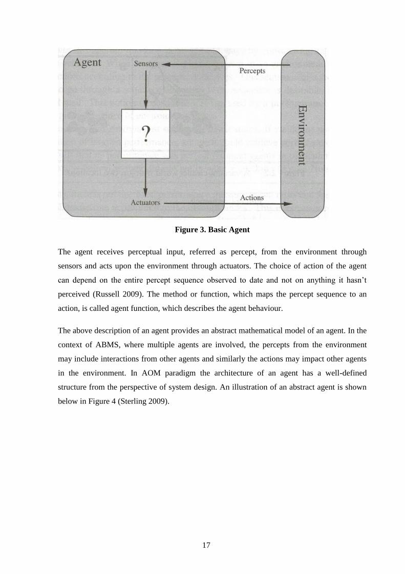
An agent is anything that can be viewed as perceiving its environment through sensors and
acting upon that environment through actuators (Russell 2009). A basic illustration of an
agent form is shown in Figure 3 (Russell 2009).
17
Figure 3. Basic Agent
The agent receives perceptual input, referred as percept, from the environment through
sensors and acts upon the environment through actuators. The choice of action of the agent
can depend on the entire percept sequence observed to date and not on anything it hasn’t
perceived (Russell 2009). The method or function, which maps the percept sequence to an
action, is called agent function, which describes the agent behaviour.
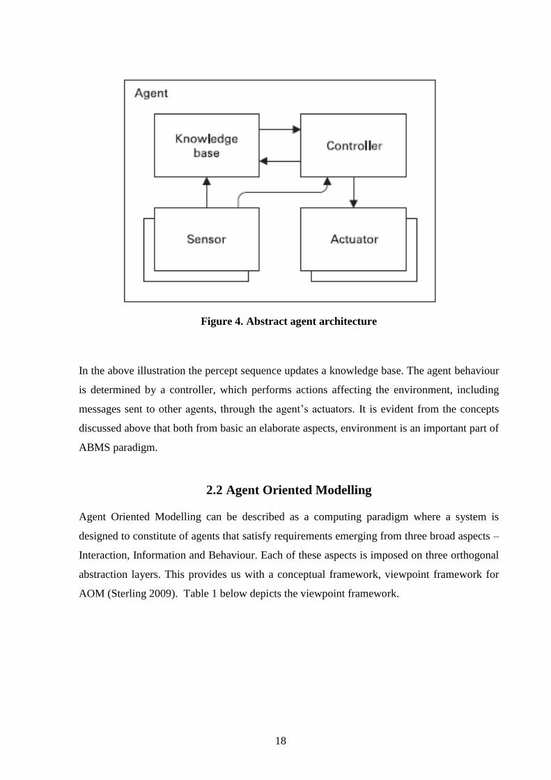
The above description of an agent provides an abstract mathematical model of an agent. In the
context of ABMS, where multiple agents are involved, the percepts from the environment
may include interactions from other agents and similarly the actions may impact other agents
in the environment. In AOM paradigm the architecture of an agent has a well-defined
structure from the perspective of system design. An illustration of an abstract agent is shown
below in Figure 4 (Sterling 2009).
18
Figure 4. Abstract agent architecture
In the above illustration the percept sequence updates a knowledge base. The agent behaviour
is determined by a controller, which performs actions affecting the environment, including
messages sent to other agents, through the agent’s actuators. It is evident from the concepts
discussed above that both from basic an elaborate aspects, environment is an important part of
ABMS paradigm.
2.2 Agent Oriented Modelling
Agent Oriented Modelling can be described as a computing paradigm where a system is
designed to constitute of agents that satisfy requirements emerging from three broad aspects –
Interaction, Information and Behaviour. Each of these aspects is imposed on three orthogonal
abstraction layers. This provides us with a conceptual framework, viewpoint framework for
AOM (Sterling 2009). Table 1 below depicts the viewpoint framework.

19
Table 1. Viewpoint framework
The abstraction layers represent three hierarchical levels of abstraction. Each intersection of
aspect and abstraction demands one or more models, which capture the details of the specific
layer from the viewpoint of the particular intersecting aspect.
The concept of viewpoint framework is important with regards to the problem statement of
this thesis in ways of reassuring the importance of environment modelling. Of major
importance for this work is the Information aspect, which denotes the knowledge of the
environment. A clear, structured and discrete representation of domain knowledge can be
efficiently interpreted and used by the agents. This clear representation of knowledge can be
described by the term ontology.
Ontology describes the concepts and relationships that are important in a particular domain,
providing a vocabulary for that domain as well as a computerized specification of the
meaning of terms used in the vocabulary.
Typically ontology describes (Giudice 2010):
Classes of things in the domain of interest
Relationships existing among things
Properties (attributes) of things.
2.3 Agent-based Modelling and Simulation
Agent based modelling and simulation is a paradigm that visualizes a system as consisting of
agents and tries to manipulate these agents to simulate a real world scenario. The focus is on
the behaviour of the individual agents. The execution of such individual agents produces the
overall simulation. However, complex environments as that of an urban environment are

20
characterized by uncertainty and interactions. In other words in addition to the behaviour of
the agent, there are intense interaction of agents with other agents and their environment
(Shvartsman 2010). Agent oriented modelling provides a method to grasp this complexity of
interactions and uncertainty by using abstract models of the system from different viewpoints.
The view points are interaction, information and behaviour. This provides a holistic picture of
the system beyond individual behaviour of the agents.
2.4 Exemplary Scenario
The paper (Nikolai 2009) provided some valuable insight into the approach of creating
exemplary scenario. The exemplary scenario of building evacuation is based the urban
operation scenario discussed the in the original research. There are few important
considerations for the exemplary scenario given the objective of the work. Firstly, it must try
to best simulate an urban operation scenario, however at a miniature scale. Secondly it will
use the agent oriented modelling paradigm for its development.
Identifying some key points from the original urban operation scenario and considering them
to build the theme of the exemplary scenario realize the first objective. These key points are
listed below:
1) Multiple environments – The system supports multiple environments (Indoor, outdoor,
etc.). Various dynamics associated with multiple environments are simulated in the system.
Agents move across these environments in urban operation. They may have different
behaviour in different environments. Environments can also be monitored.
2) Multiple roles – The system supports multiple roles, which are mapped to different agent
types.
3) Navigation and search – Navigation within building environment and search for injured
victims is one of the key tasks in the system.
4) Leading another agent – Another form of navigation where one agent follows another is
used in the system.
5) Interaction with information transfer – Agent interactions involving knowledge or
information transfer between the interacting agents.
6) Exogenous events – The urban operation environment has various exogenous events like
cave-ins or appearance of strangers.

21
The system is created with the above key points. In addition to the points to ensure that the
exemplary system is able to demonstrate the real system from both functional and non-
functional perspectives, an urban operation theme is used.
The system models a simple building evacuation scenario where a guard evacuates victims
from the rooms of a building and leads them to an internal shelter. A Shelter is a safe area in
build to protect from threats during a crisis situation. An internal shelter is a specially
designed and constructed room or area within or attached to a larger building that is designed
and constructed to be structurally independent of the larger building and to withstand the
range of natural and manmade hazards (Federal Emergency Management Agency (FEMA)
2006). The safe area in this exemplary simulation is a safe-room and the safe-room door. The
system is modelled based on the top two layers of the viewpoint framework, which are
platform independent. The following sections describe the models used for the systems where
it will be shows how the above key points are used in the design of the system.
2.5 Analysis Layer Models
This layer captures the real world perspective of the system. It omits any computational
element. The models represent the three aspect of the viewpoint framework.
2.5.1 Goal Model
The goal model for the building evacuation simulation is shows below on Figure 5. The goal
model is a graphical presentation of the goals to be achieved by the system. A motivational
scenario accompanies the goal model, which is a textual description of the system.

22
Rescue
Search for
Victims
Evacuation to
Safe Area
Collection of
Injury Information
Selection
of Victim
Evacuation to
Safe Room
Guard
Victim
Quick
Safe
Figure 5. Building evacuation goal model
The primary goal of the system is to “Rescue” and the roles involved in the operation are
“Guard” and “Victim”. This satisfies the requirement of multiple roles as per the key points
stated above. The primary goal is expanded into sub-goals in the lower layers. The order of
the sub goals in the model does not specify any particular order of the execution of goals. The
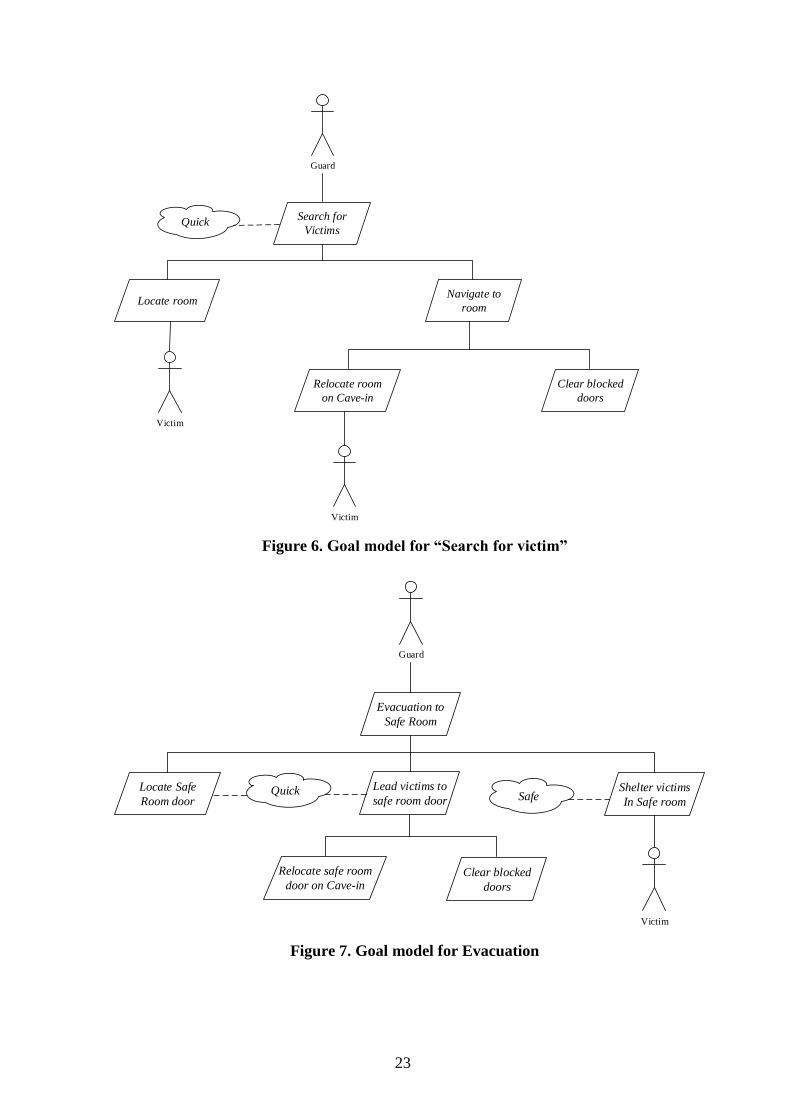
goals “Search for Victims” and “Evacuation to Safe Room” is expanded in other models as
shown in Figure 6 and Figure 7 respectively. The quality goals “Safe” and “Quick” associated
to specific goals motivates the design of the system to achieve those quality goals.
23
Search for
VictimsQuick
Guard
Locate roomNavigate to
room
Clear blocked
doors
Victim
Relocate room
on Cave-in
Victim
Figure 6. Goal model for “Search for victim”
Evacuation to
Safe Room
Guard
Locate Safe
Room door
Shelter victims
In Safe room
Clear blocked
doors
Victim
SafeLead victims to
safe room door
Relocate safe room
door on Cave-in
Quick
Figure 7. Goal model for Evacuation
24
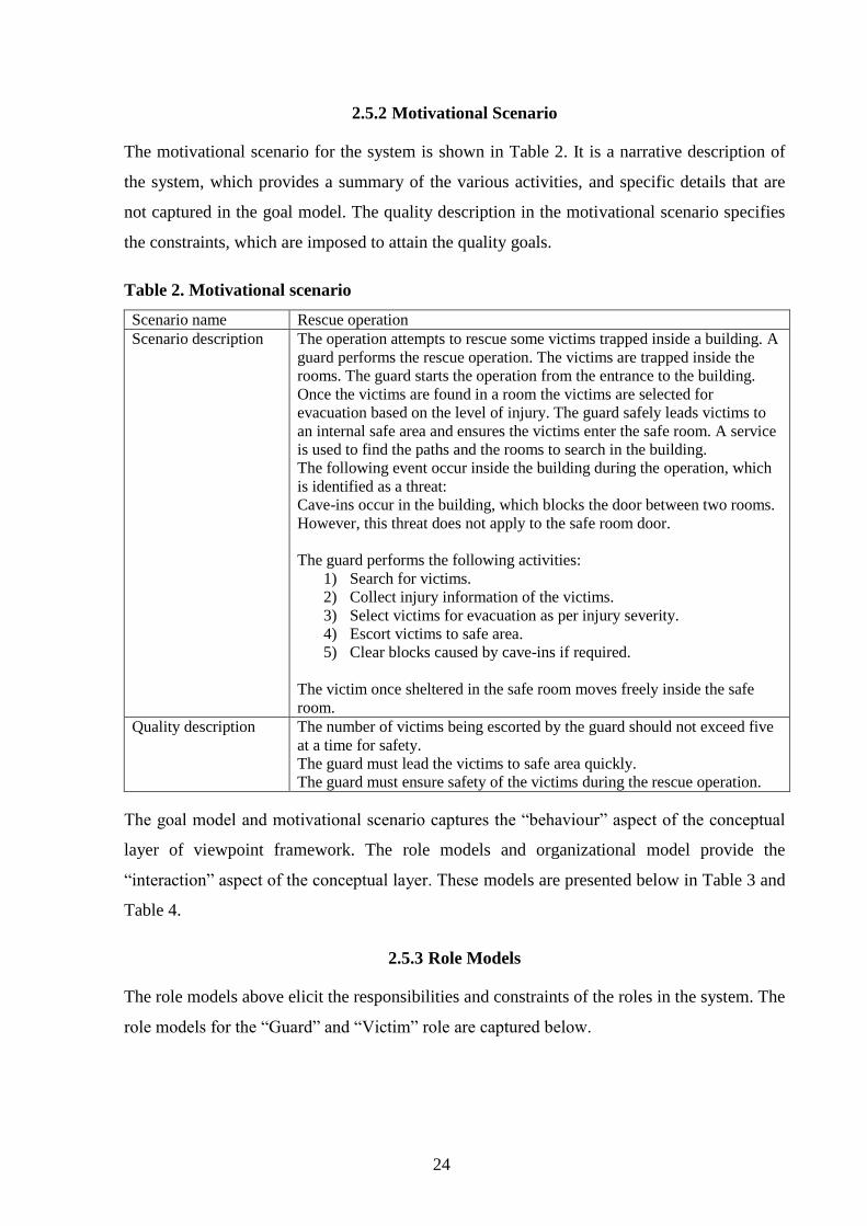
2.5.2 Motivational Scenario
The motivational scenario for the system is shown in Table 2. It is a narrative description of
the system, which provides a summary of the various activities, and specific details that are
not captured in the goal model. The quality description in the motivational scenario specifies
the constraints, which are imposed to attain the quality goals.
Table 2. Motivational scenario
Scenario name Rescue operation
Scenario description The operation attempts to rescue some victims trapped inside a building. A
guard performs the rescue operation. The victims are trapped inside the
rooms. The guard starts the operation from the entrance to the building.
Once the victims are found in a room the victims are selected for
evacuation based on the level of injury. The guard safely leads victims to
an internal safe area and ensures the victims enter the safe room. A service
is used to find the paths and the rooms to search in the building.
The following event occur inside the building during the operation, which
is identified as a threat:
Cave-ins occur in the building, which blocks the door between two rooms.
However, this threat does not apply to the safe room door.
The guard performs the following activities:
1) Search for victims.
2) Collect injury information of the victims.
3) Select victims for evacuation as per injury severity.
4) Escort victims to safe area.
5) Clear blocks caused by cave-ins if required.
The victim once sheltered in the safe room moves freely inside the safe
room.
Quality description The number of victims being escorted by the guard should not exceed five
at a time for safety.
The guard must lead the victims to safe area quickly.
The guard must ensure safety of the victims during the rescue operation.
The goal model and motivational scenario captures the “behaviour” aspect of the conceptual
layer of viewpoint framework. The role models and organizational model provide the
“interaction” aspect of the conceptual layer. These models are presented below in Table 3 and
Table 4.
2.5.3 Role Models
The role models above elicit the responsibilities and constraints of the roles in the system. The
role models for the “Guard” and “Victim” role are captured below.
25
Table 3. Victim role model
Role Name Victim
Description The role of the victim in the building
Responsibility Follow the instructions of the guard.
Move freely inside safe room
Constraints The victim must remain stationary till instructed to follow the guard.
Victim must not leave the safe room.
The victim must follow the guards strictly and promptly.
Table 4. Guard role model
Role Name Guard
Description The role of the guard in the building
Responsibility Find victims in the building
Collect injury information from the victims.
Select the victims to escort based on injury severity.
Lead victims to the safe room door.
Ensure rescued victims enter the safe room.
Clear blocks caused by cave-ins if required.
Constraints The search and rescue must be quick.
Navigation will prefer unblocked routes.
The guard must not leave the safe room door before rescued victims have
entered the safe room.
Severely injured victims will have higher priority in the evacuation.
Ensure victims are lead to safe room in shortest time.
2.5.4 Organization Model
The organizational model captures the relation between the roles. The roles in this system are
related by a control relationship, in which the guard controls the victim (see Figure 8).
Guard Victim
isContrlledBy
Figure 8. Organization model
2.5.5 Domain Model
The domain model captures the “information” aspect of the conceptual layer. The domain
model is of important consideration, especially for this work, because of the significance of
environment in urban operations. The domain model captures the domain entities. A domain
entity is a modular unit of knowledge handled by a sociotechnical system. A domain entity is
conceptually an object type. An instance of a domain entity is hence called an environment
26
object. An environment itself can be modelled as one of the domain entities (Sterling 2009).
The domain model captures the relations between the various entities of the system. However,
to build the domain model of the systems, it is important to identify the environment and
resources in the domain of the system. A resource model, as shown below in Table 5, depicts
the information about resources.
Table 5. Resource model
Resources(s) Roles(s) Environment(s)
Room Guard, Victim Hazard Area
Gate Guard Building
Door Guard Hazard Area
Route Guard Hazard Area
Safe room door Guard, Victim Safe Area
Safe room Victim Safe Area
The resource model identifies the resources in the system and the various environments they
are created or stored. The system identified two environments in a parent environment called
“Building”. The two environments – “Safe Area” and “Hazard Area” are domain entities in
the domain model. The roles column shows the roles that have a relation with the resources.
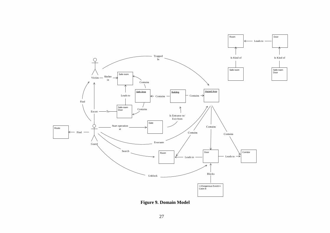
The domain model for the system is shown below in Figure 9. An environment itself can be
modelled as a domain entity (Sterling 2009). The entities “Hazard Area” and “Safe Area” are
environments inside the “Building” entity. The model captures the relations between the roles
and resources. As seen in the diagram, there are two parts of the domain model. This is in
attempt to capture the hierarchical relation between “Door” / “Safe Room Door” and “Room”/
”Safe Room”. It has been shows separately not to obscure the main diagram. The entities
“Building”, “Safe Area” and “Hazard Area” are underlines to denote their role as
environments in addition to domain entities.
One of the issues the author came across during the modelling of domain is with the
exogenous event “Cave-In”. Events are not modelled as domain entities but “Cave-in” event
is significant due to its relation with the domain entity door. Cave-in blocks a door, which is
important information to be captured in the domain model, as “Unblock” is a relation between
the door and the guard role. Considering the significance of the event, it was added to the
domain model using the stereotype <<Exogenous Event>>
27
Hazard Area
Gate
Victim
Corridor
Guard
Escort
Room
Contains
Door
Leads to
<<Exogenous Event>>Cave-in
Find
Trapped
In
Evacuate
Safe-room Door
Building
Contains
Unblock
Leads to
Start operation
at
Search
Safe Area
Safe room
Contains
Contains
Shelter
in
Is Entrance to/
Exit from
Leads to
Blocks
Room Door
Leads to
Is Kind of Is Kind of
Safe room Safe-room Door
Route
Find
Figure 9. Domain Model
28
2.6 Design Layer Models
The design models view the system from a platform independent computational perspective.
The three aspects of interaction, information and behaviour present the system using a set of
models. The subsequent sections describe the models for the design layer.
2.6.1 Agent Models
Agent model is part of the interaction aspect models. It captures the agents in the system,
which can play various roles as of the analysis layer. The developed system has two agents –
GuardAgent and VictimAgent. The agent models are shown below in Table 6 and Table 7
accordingly. The models describe the roles that the agent will be playing in the system and
also the environment considerations, which relate the agent with the various domain resources
that it will have to consider in some ways.
Table 6. GuardAgent model
Agent Type Name GuardAgent
Description The agent representing as Guard.
Role(s) Guard
Environmental consideration Room, Door, Cave-in, Safe room door, Gate,
Route
Table 7. VictimAgent model
Agent Type Name VictimAgent
Description The agent representing as Injured
Role(s) Injured
Environmental consideration Room, Safe Room, Safe room door
2.6.2 Acquaintance Model
The acquaintance model depicts the relationship between the agent types and the roles they
play. The model shows the cardinality of the agent types and roles in their relations among
each other. The acquaintance model is as shown below on Figure 10.

29
Guard Victim
GuardAgent VictimAgent
1
1 1
1
1 *
Figure 10. Acquaintance model
2.6.3 Interaction Models
Interaction models as the name suggests constitutes the view of interaction aspect. There are
two types of interaction model used for this system – Interaction frame diagram and
Interaction protocol. The diagram below (see Figure 11) shows the interaction frame
diagram. It captures the various interactions between the guard and the victim, however it
does not indicate any sequence of the interaction. In addition to the interaction between agent
types it also depicts the interaction on exogenous events, like the one shown for “Cave-in”.

30
GuardVictim
Provide Injury Information
Injury Information provided
Follow me
Follow Guard
Move to Safe room
Moved into safe room
Cave-inGuardPerform navigation Query
Figure 11. Interaction frame diagram
The second interaction model – Interaction protocol provides the information of the sequence
of interaction between the agents. The protocol diagram is elaborate and is capable of
capturing details of the communication. The protocol diagram is shown below for the system
on Figure 12.

31
sd Rescue protocol
:Victim :Guard
Loop [Victims trapped]
Alternative
Option
Loop[Lead victims not in safe room]
[In Room]
[First Visit to Room][Trapped inthe room] Provide injury information
Injury Information
<<blocking>> [Victims Selected]
Follow me1 <= i <= 5
Guard is followed
[at Safe room door]
<<blocking>>[Victim has not
arrived atSafe room door]
Move into safe room
Entered Safe room
[At safe room door]
Figure 12. Interaction Protocol
The diagram has constructs for loop, option and alternate flows to capture the sequence and
conditions for the interaction between the agents. The notations use the standard AUML
notations, explained in Huget et al. (Huget 2004) and Winikoff (Winikoff 2005). The Loop
block repeats the interaction till the condition in square brackets is true. The option block
executes the interaction only if the guard condition is true. The alternative blocks have
multiple compartments, where only one is executed if the guard condition for the block is
satisfied. The protocol in addition captures the wait between interaction sequence for a
condition to be satisfied using the <<blocking>> constraint.

32
2.6.4 Knowledge Model
The knowledge model for the system is as shown below. The knowledge mode is a part of the
information aspect of the viewpoint framework. It depicts the knowledge resource that agents
carry. Many of the knowledge elements are derived from the domain model of the analysis
layer. The knowledge model identifies the information that the agents “know about”. The
diagram also shows the relationship between the various knowledge items.
Some important points to be considered in the knowledge model are:
The Building agent object holds the information of all building elements and their
relationships.
The Guard agent does not have full knowledge of the building item, as the guard is not
aware of the routes in the building and how they are connected. The guard also has no
knowledge about the safe room.
The Victim has knowledge about the safe room and the location of the guard.
The service “NavigationService” has access to the building data.
The guard agent has some data knowledge items of its own. These items are used in
executing the responsibilities of the guard.
As shown on the Figure 13, it tries to avoid proposing complex data structure, as it may
impose an implementation, which may not be best choice for a specific platform. Therefore
the model attempts to capture the knowledge entities and the cardinality relation between
them, however not complete implementation details.
An important point observed in the modelling task is that the modelling order of the models of
the viewpoint framework can be iterative. The previous models provide the basic information
for the next models in many cases. However, it may so happen that in the process of creating
a model, some important insights are discovered in the previous models. In this task some
important knowledge items like “PathNode” and “VictimInjury” were found during modelling
the behaviour models.

33
GuardAgent/Guard
numberOfVictimsLead: Integer
Building
Corridor
SafeRoomDoor
Location
SafeRoom
Geometry
Room
Identifier: Integer
Geometry
Door
Identifier: IntegerisBlocked: Boolean
Location
1
*
1
*
1
1
Gate
Location
1
1
1 1
<<Service>>NavigationService
NavigationPath findRoom(PathNode current)
Knows about
Knows about
1 1
1 *
Knows about1 *
Knows about
1
1
Knows about
Knows about
1
1
NavigationPath findSafeArea(PathNode current)
1
1
*
Knows about
1
*
VictimAgent/Victim
Identifier: Integer
VictimLocationKnows about
*
1
1
1
Injury: Integer
NavigationPath
GuardLocation
AssessedVictims
RoomsToRevisit
VictimInjury
victimID: Integer injury: Integer
1*
1*
Location
node: PathNode
Knows about
PathNode
type: Enumeration {ROOM, DOOR,CORRIDORSAFEROOM,SAFEDOOR, GATE}
id: Integer
1
1
1
1
*VictimInjury next()isEmpty()
PathNode next()isEmpty()
Figure 13. Knowledge Model
2.6.5 Scenarios
Scenarios are part of the behaviour aspect of the viewpoint framework. Scenarios identify the
activities involved in achieving the goals by the agents of the system. The scenarios are either
triggered or they are executed as part of another scenario. The scenarios for the system are as
shown below in Table 8 - Table 18. These scenarios primarily capture the sequence of the
activities based on the “Conditions” column, the agents who are taking part in the activity in
the “AgentType/Role” column and the knowledge resources that are accessed for the activity.
The access is classified as Read (R)/Write (W). It should be noted that presence of a
knowledge resource for an activity does not imply that the resource is used on every instance
of execution of the activity, it may be accessed only during the first time for example for

34
initialization. An example of this can be found in scenario 1 (see Table 8), where the activity
“Search for victims” uses the resource Gate, only the first time when the guard is at the gate.
Another point is that a resource can be mentioned as being accessed for an activity, even if it
is used only to check the condition for the activity. An example can be found in scenario 6 –
“Evacuation of victims to safety”, where the resource “RoomsToRevisit” is accessed in
activity “Collect Injury Information” to check the condition for the activity.
Table 8. Scenario 1
SCENARIO 1
Goal Rescue victims
Initiator Guard
Trigger Beginning of rescue operation
DESCRIPTION
Condition Step Activity AgentType/Role Resource Quality
Loop till
victims
are
trapped
2 Search for
victims
(Scenario 2)
GuardAgent/Guard
VictimAgent/Victim
Gate(R),
Room(R),
Door(R,W),
Corridor(R),
NavigationPath(R,W),
GuardLocation(R,W),
VictimLocation(R)
Quick
3 Escort
victims to
safety
(Scenario 6)
GuardAgent/Guard
VictimAgent/Victim
AssesedVictims(R,W),
RoomToRevisit(R,W),
Room(R),
Door(R,W),
Corridor(R),
GuardLocation(R,W),
NavigationPath(R,W),
VictimLocation(R,W)
SafeRoomDoor(R),
SafeRoom(R)
Quick,Safe
Table 9. Scenario 2
SCENARIO 2
Goal Search for victims
Initiator Guard
Trigger
DESCRIPTION
Condition Step Activity AgentType/Role Resource Quality
1 Locate
candidate
room
GuardAgent/Guard,
VictimAgent/Victim
Room(R),
Door(R),
Corridor(R),
NavigationPath(W),
GuardLocation(R),
VictimLocation(R)
Quick
35
2 Navigate to
candidate
room
(Scenario 3)
GuardAgent/Guard,
VictimAgent/Victim
Room(R),
Door(R,W),
Corridor(R),
GuardLocation(R,W),
NavigationPath(R,W),
VictimLocation(R,W)
Quick
Table 10. Scenario 3
SCENARIO 3
Goal Navigate to candidate room
Initiator Guard
Trigger
DESCRIPTION
Condition Step Activity AgentType/Role Resource Quality
1 Follow the
path to the
room
GuardAgent/Guard Room(R),
Door(R),
Corridor(R),
NavigationPath(R),
GuardLocation(R,W)
Table 11. Scenario 4
SCENARIO 4
Goal Relocate candidate room
Initiator Guard
Trigger Cave-in occurred
DESCRIPTION
Condition Step Activity AgentType/Role Resource Quality
Guard is
navigating
to room
1 Locate
candidate
room
GuardAgent/Guard,
VictimAgent/Victim
Room(R),
Door(R),
Corridor(R),
NavigationPath(W),
GuardLocation(R),
VictimLocation(R)
Quick
Table 12. Scenario 5
SCENARIO 5
Goal Clear blocked door
Initiator Guard
Trigger Reached a blocked door
DESCRIPTION
Condition Step Activity AgentType/Role Resource Quality
1 Unblock
the door
GuardAgent/Guard
Door(R)

36
Table 13. Scenario 6
SCENARIO 6
Goal Evacuation of victims to safety
Initiator Guard
Trigger
DESCRIPTION
Condition Step Activity AgentType/Role Resource Quality
First visit
to the room
2 Collect
injury
information
(Scenario 7)
GuardAgent/Guard,
VictimAgent/Victim
Injury(R),
RoomToRevisit(R),
AssessedInjured(R,W),
GuardLocation(R)
3 Select
victims
(Scenario 8)
GuardAgent/Guard,
VictimAgent/Victim
AssessedInjured(R,W),
GuardLocation(R),
numberOfVictimsLead(W)
Safe
Room has
unselected
victims left
4 Record room
for revisit
GuardAgent/Guard RoomToRevisit(W)
5 Lead victim
to safe room
(Scenario 9)
GuardAgent/Guard,
VictimAgent/Victim
GuardLocation(R,W),
Room(R),
Door(R),
Corridor(R),
VictimLocation(W),
SafeRoom(R),
SafeRoomDoor(R),
numberOfVictimsLead(R,W)
Quick,
Safe
Table 14. Scenario 7
SCENARIO 7
Goal Collect injury information
Initiator Guard
Trigger
DESCRIPTION
Condition Step Activity AgentType/Role Resource Quality
Repeat for all
victims in the
room
1 Collect injury
information
from victim
GuardAgent/Guard,
VictimAgent/Victim
Injury(R),
AssessedInjured(R,W),
GuardLocation(R)
Safe
Table 15. Scenario 8
SCENARIO 8
Goal Select victims
Initiator Guard
Trigger
DESCRIPTION
Condition Step Activity AgentType/Role Resource Quality
Loop, till
maximum
capacity (5 or
all, whichever
is less) of
victims are
selected from
1 Select victim
with the most
severe injury
among the
unselected
victims in the
room.
GuardAgent/Guard,
VictimAgent/Victm
AssessedInjured(R,W)
numberOfVictimsLead(W)
Safe

37
the room.
2 Selected
victim
follows the
guard
VictimAgent/Victi
m,
GuardAgent/Guard
GuardLocation(R),
VictimLocation(W)
Table 16. Scenario 9
SCENARIO 9
Goal Lead Victim to Safe Room
Initiator Guard
Trigger Victims selected from the room
DESCRIPTION
Condition Step Activity AgentType/Role Resource Quality
1 Find route to
safe room
door
GuardAgent/Guard Room(R),
Door(R),
Corridor(R),
NavigationPath(W),
GuardLocation(R),
SafeRoomDoor(R)
Quick
2 Lead victim
to safe room
door
VictimAgent/Victim,
GuardAgent/Guard
NavigationPath(R,W),
Room(R),
Door(R,W),
Corridor(R),
SafeRoomDoor(R),
GuardLocation(R,W),
VictimLocation(W)
Quick
Repeat
for all
victims
lead
3 Shelter
victim in
Safe room
(Scenario 11)
VictimAgent/Victim,
GuardAgent/Guard
VictimLocation(R,W),
SafeRoom(R),
numberOfVictimsLead(R,W)
Safe
Table 17. Scenario 10
SCENARIO 10
Goal Relocate safe room door
Initiator Guard
Trigger Cave-in occured
DESCRIPTION
Condition Step Activity AgentType/Role Resource Quality
Guard is
leading
the
victims
1 Find route to safe
room door
GuardAgent/Guard Room(R),
Door(R),
Corridor(R),
NavigationPath(W),
GuardLocation(R),
SafeRoomDoor(R)
Quick
Table 18. Scenario 11
SCENARIO 11
Goal Shelter victim in safe room
Initiator Guard

38
Trigger
DESCRIPTION
Condition Step Activity AgentType/Role Resource Quality
Victim
Reached the
safe room
door
1 Guard
instructs
victim to
move in to
safe room
GuardAgent/Guard
VictimAgent/Victim
VictimLocation(R)
numberOfVictimsLead(W)
2 Victim
moves in to
safe room
VictimAgent/Victim SafeRoom(R)
VictimLocation(W)
3 Victims
moves freely
inside safe
room
VictimAgent/Victim VictimLocation(W)
SafeRoom(R)
2.6.6 Behaviour Models
The behaviour mode captures the agent’s individual behaviour and the logic, which it
executes during its life cycle (execution cycle). The behaviour consists of activities and
actions, which are triggered by some conditions called rules. The actions are of three types-
physical action, communicative action, and epistemic action. Epistemic actions occur when an
entity is updating a data. A double-pointed arrow denotes its notation (>>).
The behaviour model for a part of the building evacuation system is shown in the Figure 14.
This model primarily depicts the behaviour of “Search Victim” goal. Some points to note
about the model are discussed as follows:
1) The behaviour model is not a series of activities that will be executed in one cycle.
Specific activities are executed in the behaviour model based on the rules that are
triggers during the execution cycle.
2) One observation found when implementing the model is that, the nested structure of
the activities in the behaviour model can be very well represented in the code for the
execution cycle of the Repast Agent. The code snippet of the GuardAgent is shown in
Figure 15. As can be found from the code, the variable “act” follows the nested
activity structure of the behaviour model. There are areas of improvement where no
activity is done in some cycles, just to change the value of the variable, however, the
code could be easily represented in terms of the model. This is a useful outcome of
agent oriented modelling, because the models are platform independent, so this
representation can be achieved on any platform.

39
GuardAgent/Guard
Rescue victims
Search victims
Locate RoomNavigationService.findRoom(GuardLoc
ation.PathNode)
R1
Gate
Location
U
R3
Navigate to room{nextPathNode: PathNode,
nextLocation:LocationbuildingElement: BuildingElement}
R4
Move to nextLocation
R5
R6
R7 Cave-in occured
NavigationPath
isEmpty()
PathNode next()
U
{NavigationPath.isEmpty = true}
Unblock Door
GuardLocation
PathNode
type: Enumerationidentifier: Integer
Location getLocation()
U
Door
Identifier: IntegerisBlocked: Boolean
Location
U
{GuardLocation.PathNode.type = DOOR
andDoor.isBlocked = true}
{GuardLocation.type = ROOM}
Re-Locate RoomNavigationService.findRoom(GuardLoc
ation.PathNode)
U
{isOpearationComplete = false}
R7
Evacuate to safe area{GuardLocation.type =
ROOM}
R2
isOpearationComplete = true
nextPathNode = NavigationPath.next()and
buildingElement = Building.getElement(nextPathNode)
andnextLocation =
buildingElement.getLocation()
Figure 14. Behaviour model

40
Figure 15. GuardAgent execution cycle
41
3. Simulation of Physical Environment for Training Scenarios
This chapter describes the implementation of the system in Repast Simphony. It starts with
the explanations of GIS which is a technology used in the implementation.
3.1 Representing Environment
This chapter describes a preliminary study of two ontologies that support the representation of
urban environment in 3D. The study has been done with the following objectives:
A suitable ontology to represent the environment. The ontologies are 3D, thus
representing a much more realistic environment.
The content provides lot more visual and semantic (doors, windows, walls etc.)
information than basic shapefiles.
An objective to decouple the environment from the simulation, where the complex
environment can be developed separately in standard industry format and imported
into an agent simulation toolkit like repast. This is an objective with a large scope and
thus demands lot more work.
3D city models are of two types, design and real world models (M. El-Mekawy 2010). The
design models are made for architectural purpose in the building industry to capture the
details of the building of the construction. Building Information Modelling is a process that
supports the building design models in the industry. Real world models are geo spatial in
nature. They capture the geographical information of buildings and other spatial objects. Both
these models can represent the details of an environment.
The two most prominent semantic models for the representation of BIM and geospatial
objects are Industry Foundation Classes (IFC) and City Geography Markup Language
(CityGML), respectively (M. El-Mekawy 2010).
3.1.1 CityGML
CityGML is a common semantic information model representing different 3D urban and
geographical objects that can be shared among different applications (M. El-Mekawy 2010).
CityGML information is stored and exchanged as GML schema. Geography Markup

42
Language (GML) is an XML grammar written in XML Schema for the modelling, transport,
and storage of geographic information. GML is another format of representing GIS data. It
includes both spatial and non-spatial data (OpenGIS® Geography Markup Language (GML)
Implementation Specification 2004). City GML captures multiple level of details in the city
model, LOD0 to LOD4, where LOD4 is the maximum details.
3.1.2 IFC
IFC (Industry Foundation Classes) is information standard for building industry. Its main
objective is to facilitate interoperability in the building industry. IFC does not support geo
spatial data. It is primarily aimed for Industry environments.
In this work we focus primarily on the support for building environments. Both these standard
have a framework of classes to support the building objects. In the study performed, the
following points were identified from sources that supported CityGML for the simulation
environment over IFC.
IFC has large number of classes for the Industry environment, which capture very high
level of details that are less likely to be relevant for the simulation or urban operations.
For example there are classes for heating, ventilation, air conditioning and structural
calculation, however few are for are used for the representation of building an
architectural elements. (M. Ö. El-Mekawy 2012). Where as in CityGML the classes
are more for building and city environments which are more relevant for the purpose.
The framework structure of IFC gives high flexibility, which means there is more than
one way to connect various classes to for the same structure. This can cause a software
implementation to be more difficult, whereas in CityGML the relationship between the
classes are static, thus there is only one way to various parts of the building.
Support for Geographical information in cityGML
Based on the above comparative study, CityGML is selected for future works.
3.1.3 GIS and Repast Simphony
The system developed as part of the thesis work, is based on a popular agent based platform –
Repast and a popular spatial data format called shapefile. This section will elaborate some
points about these two systems used for the implementation.
43
Geographic Information System is a computer system capable of assembling, storing,
manipulating, analysing and displaying geographically referenced information, i.e. data
identified according to their location. The term geographically referenced information
emphasize that the information must have a geographic location associated with it. Real world
geographic information has three properties – location, attributes and spatial relation.
Location refers to the geographic location to which the information refers. The location is
always measured with reference to some spatial coordinate system. Attributes refer to
information about the location, e.g. population of a location. Spatial relation is the property,
which describes the special attributes, e.g. shape of an object or the spatial relation an object
shares with other objects. These properties give a structure to the real geographic information
for representation in a computer.
GIS data can be represented in two formats, Raster GIS Data and Vector GIS Data. Raster
GIS Data represents earth surface as a grid of evenly sized cells. Each cell represents a
particular area of the surface. Attributes are assigned to a cell, thus associating the attribute to
that portion of the surface the cell represents. The size of these cells decides the quality of the
spatial resolution. The smaller the cells or pixels are, the higher the spatial resolution. Raster
data is suitable to represent continuously changing attributes e.g. elevation (Rose 2009).
Vector data provide a way to represent real world features within the GIS environment. A
feature is anything you can see on the landscape. A vector feature represents a shape using
geometry. The geometry is formed using vertices. A vertex can represent a single point or can
form a polyline or polygon by interconnecting with other vertices. This form of geometry
allows vector data to capture spatial relations among features (Sutton 2009). Attribute is a part
of GIS information, thus features have associated attributes. Figure 16 (Sutton 2009) shows a
feature hierarchy.
44
Figure 16. GIS Feature Hierarchy
Topology is defined as the spatial relationship between adjacent or neighbouring features
(Rose 2009). One of the most popular file formats to store GIS data is ESRI shape file, which
is nontopological geometry and attribute information for the spatial features in a data set. The
geometry for a feature is stored as a shape comprising a set of vector coordinates
(Environmental Systems Research Institute, Inc. 1998).
Repast Simphony, also referred as Repast S, is a popular agent based simulation toolkit. The
design methodology in Repast S is based on two concepts, Context and Projection. The idea
of context and projections has provided repast an infrastructure that supports highly modular
set of behaviours and relationships (Repast 2009).
The core data structure in Repast S is context. From the modelling perspective, context
represents an abstract population. The objects in the context constitute the abstract population
of the context and are known as proto-agents. Context does not provide any mechanism for
interaction between the proto-agents. Context provides the basic infrastructure to define the

45
population however it does not provide the proto-agents with any concept of space or relation.
Context itself can have a state and behaviour associated with it. They can have a hierarchy
allowing sub-contexts. These properties make a context more than just a container. Proto-
agents can move between contexts. As a result, proto-agents that are designed to engage in
behaviour on the basis of their environment can switch behaviours very easily when they
migrate into another context. This property of context can be used to integrate the
environment model into the simulation with a high degree of logical modularity. Figure 17
shows a possible hierarchy of contexts. Moving the agent between the sub-contexts, “Indoor”
and “Outdoor”, can alter the behaviour of an agent.
Figure 17. Repast context hierarchy
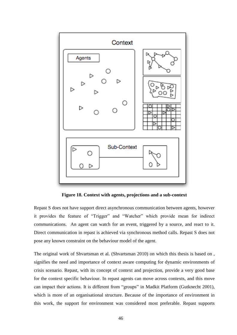
Projections impose a structure on the population of the context. Proto-agent population is
realized once a projection is applied to it. This allows the proto-agents to interact with one
another. In other works once a projection is applied, the proto-agents gain the perception of
space and relation. Multiple projections can be applied on a context, thereby allowing
multiple types of relationship between proto-agents as shown in Figure 18 (Repast 2009)
46
Figure 18. Context with agents, projections and a sub-context
Repast S does not have support direct asynchronous communication between agents, however
it provides the feature of “Trigger” and “Watcher” which provide mean for indirect
communications. An agent can watch for an event, triggered by a source, and react to it.
Direct communication in repast is achieved via synchronous method calls. Repast S does not
pose any known constraint on the behaviour model of the agent.
The original work of Shvartsman et al. (Shvartsman 2010) on which this thesis is based on ,
signifies the need and importance of context aware computing for dynamic environments of
crisis scenario. Repast, with its concept of context and projection, provide a very good base
for the context specific behaviour. In repast agents can move across contexts, and this move
can impact their actions. It is different from “groups” in Madkit Platform (Gutknecht 2001),
which is more of an organisational structure. Because of the importance of environment in
this work, the support for environment was considered most preferable. Repast supports
47
indirect communication using watchers and triggers, which is a useful feature to simulate
exogenous events. Exogenous events are primary part of the environment that is being
modelled. Repast has built in support for importing shapefiles, and many other library utilities
for network and search, which can be of assistance in modelling the behaviour. Based on a
preliminary review of the three platforms, MadKit, Repast Simphony and MASON (S. Luke
2013) – Repast Simphony was chosen for the work.
3.2 Simulation of Physical Environment by Repast Simphony
The focus on the environment in this work has been considered in the implementation of the
environment model in repast. One of the best available realistic environments modelling
currently available in repast is (Geographical information systems (GIS) data. Repast supports
ESRI shapefile to import and use GIS Data. The project Repastcity3 (Repastcity 2012) has
provided some valuable insight into various operation of Repast Simphony used in this work.
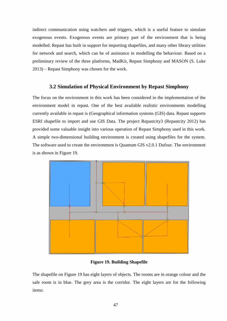
A simple two-dimensional building environment is created using shapefiles for the system.
The software used to create the environment is Quantum GIS v2.0.1 Dufour. The environment
is as shown in Figure 19.
Figure 19. Building Shapefile
The shapefile on Figure 19 has eight layers of objects. The rooms are in orange colour and the
safe room is in blue. The grey area is the corridor. The eight layers are for the following
items:
48
Building area – This is the grey building area, part of which is visible as the grey
corridor.
Rooms
Safe Room
Door – The doors are in pairs as light blue dots. The pairing allows the simulation of
blocked doors where the route between the paired doors is not considered to find the
paths.
Safe room door
Corridor – The corridor has multiple points which is used for navigation
Routes – This layer is added to link the various points in the building which helps to
create the route map.
Gate – This is for the building gate.
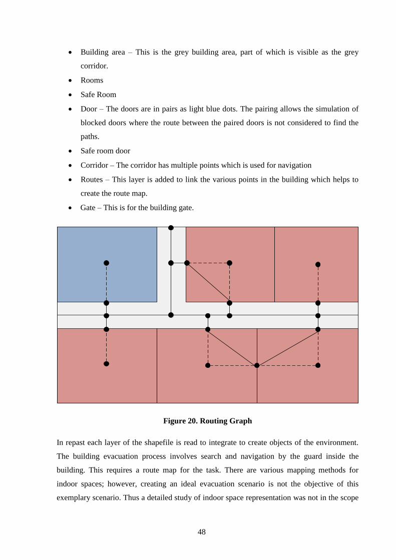
Figure 20. Routing Graph
In repast each layer of the shapefile is read to integrate to create objects of the environment.
The building evacuation process involves search and navigation by the guard inside the
building. This requires a route map for the task. There are various mapping methods for
indoor spaces; however, creating an ideal evacuation scenario is not the objective of this
exemplary scenario. Thus a detailed study of indoor space representation was not in the scope
49
of the work. The work in paper by Goetz (Goetz, Using Crowdsourced Geodata for Agent-
Based Indoor Evacuation Simulations 2012) has provided some valuable insight into the
usage of a formal method – Weighted Indoor Route Graph (Goetz, Formal Definition of a
User-adaptive and Length-optimal Routing Graph for Complex Indoor Environments 2011),
to create routes in the indoor space.
The diagram on Figure 20 shows the application of the method. The navigation in the corridor
in this method is along the central line, which connects to the doors from the point closest to
the door on the central line. There are points inside the rooms, which are connected with
dashed lines to signify that the dots inside the room are not created in the shapefile. They are
the centroids of the room geometry, located using inbuilt feature of Repast. The doors
represent paired door in this diagram with edges between them, however they are not relevant
to be shown in the route map as they are considered to be of either zero weight (unblocked) or
infinity (blocked).
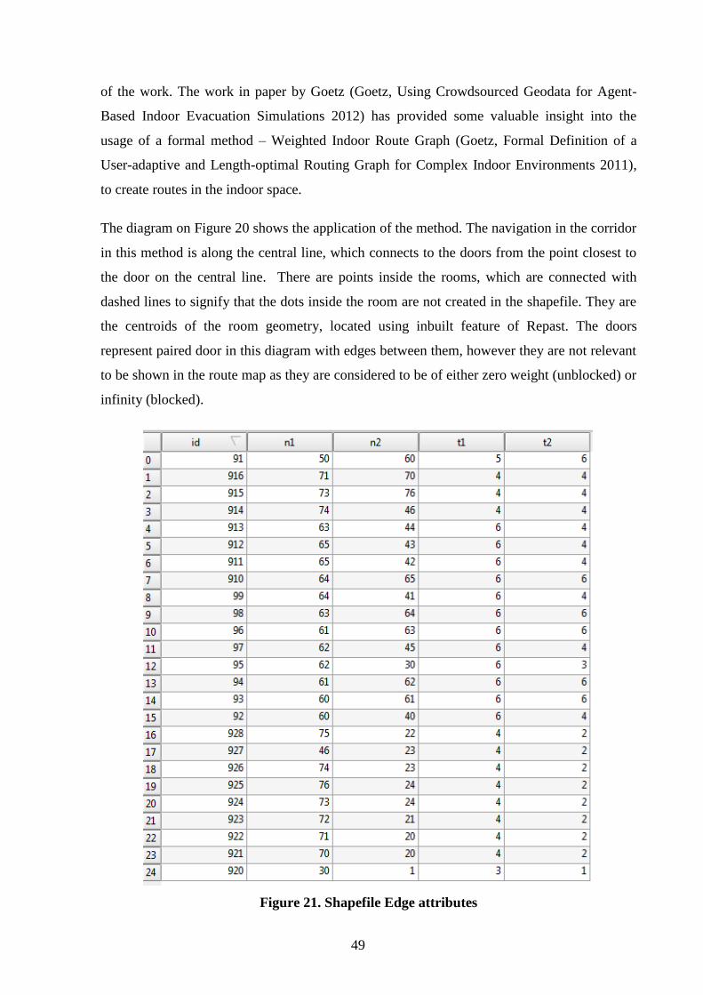
Figure 21. Shapefile Edge attributes
50
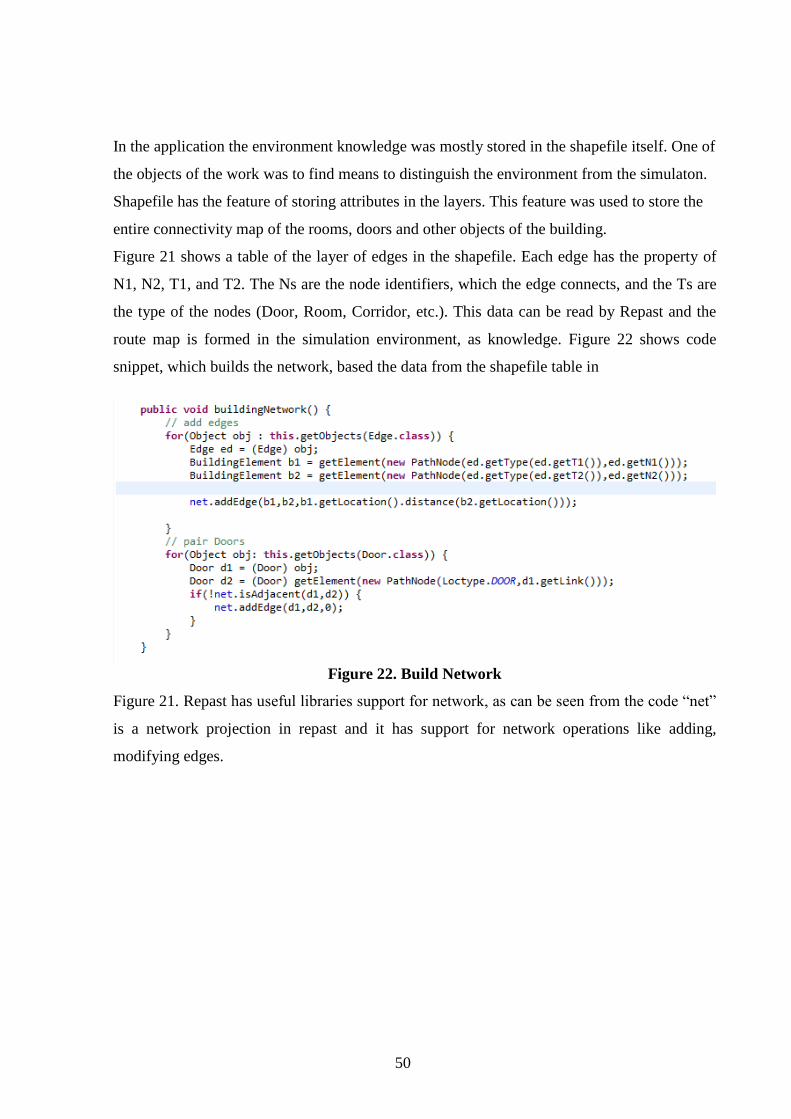
In the application the environment knowledge was mostly stored in the shapefile itself. One of
the objects of the work was to find means to distinguish the environment from the simulaton.
Shapefile has the feature of storing attributes in the layers. This feature was used to store the
entire connectivity map of the rooms, doors and other objects of the building.
Figure 21 shows a table of the layer of edges in the shapefile. Each edge has the property of
N1, N2, T1, and T2. The Ns are the node identifiers, which the edge connects, and the Ts are
the type of the nodes (Door, Room, Corridor, etc.). This data can be read by Repast and the
route map is formed in the simulation environment, as knowledge. Figure 22 shows code
snippet, which builds the network, based the data from the shapefile table in
Figure 22. Build Network
Figure 21. Repast has useful libraries support for network, as can be seen from the code “net”
is a network projection in repast and it has support for network operations like adding,
modifying edges.
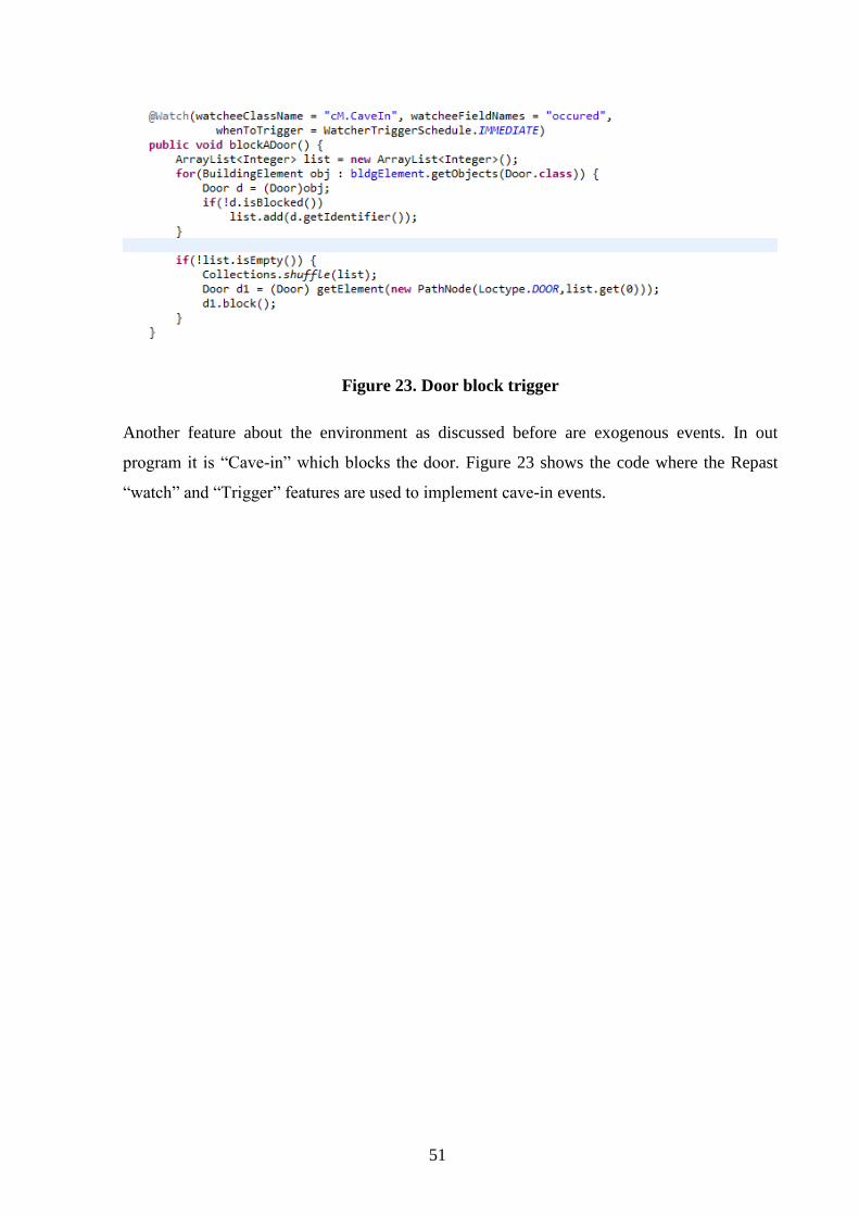
51
Figure 23. Door block trigger
Another feature about the environment as discussed before are exogenous events. In out
program it is “Cave-in” which blocks the door. Figure 23 shows the code where the Repast
“watch” and “Trigger” features are used to implement cave-in events.

52
4. Conclusion
The objective of the work was to develop a highly simplified exemplary scenario of urban
operation as an initial development of an urban operation simulation with the focus on
environment. A second objective was the preliminary comparative study of two popular
industry standards for the representation of physical environment to find the one suitable for
the urban operation scenario.
As directed by the objective an exemplary building evacuation operation scenario was
modelled using agent oriented modelling. Based on that model a simulation was developed on
an agent-based platform called Repast.
In the course of the thesis two industry specifications for environment representation -
CityGML and IFC were selected for comparative study in terms of their suitability to be used
as the environment data for the urban operation environment.
Based on the work done as part of the thesis, some key points are concluded. Firstly, agent
oriented modelling using viewpoint framework provided a clear picture of the dynamics of the
simulation as it was able to handle the complexity by capturing the various aspects of the
view point framework. The models with their structured approach simplified the complex
operations and more importantly exposed the areas where there was lack of clarity in the
specification from the three aspects of interaction, information and behaviour.
Secondly, the development of Repast Simphony provided support for environment modelling
using contexts and projections, thus reducing the development complexity. It provides library
support for various functions including networks and geospatial operation. The feature of
Repast for importing shapefiles was instrumental for integrating the environment data. The
development experience concludes that the complexity of the simulation can be handled with
repast, thus it can be used to implement more advanced scenarios.
Thirdly, the preliminary comparative study of the two specifications for environment
representations found CityGML to be more suitable for this purpose.
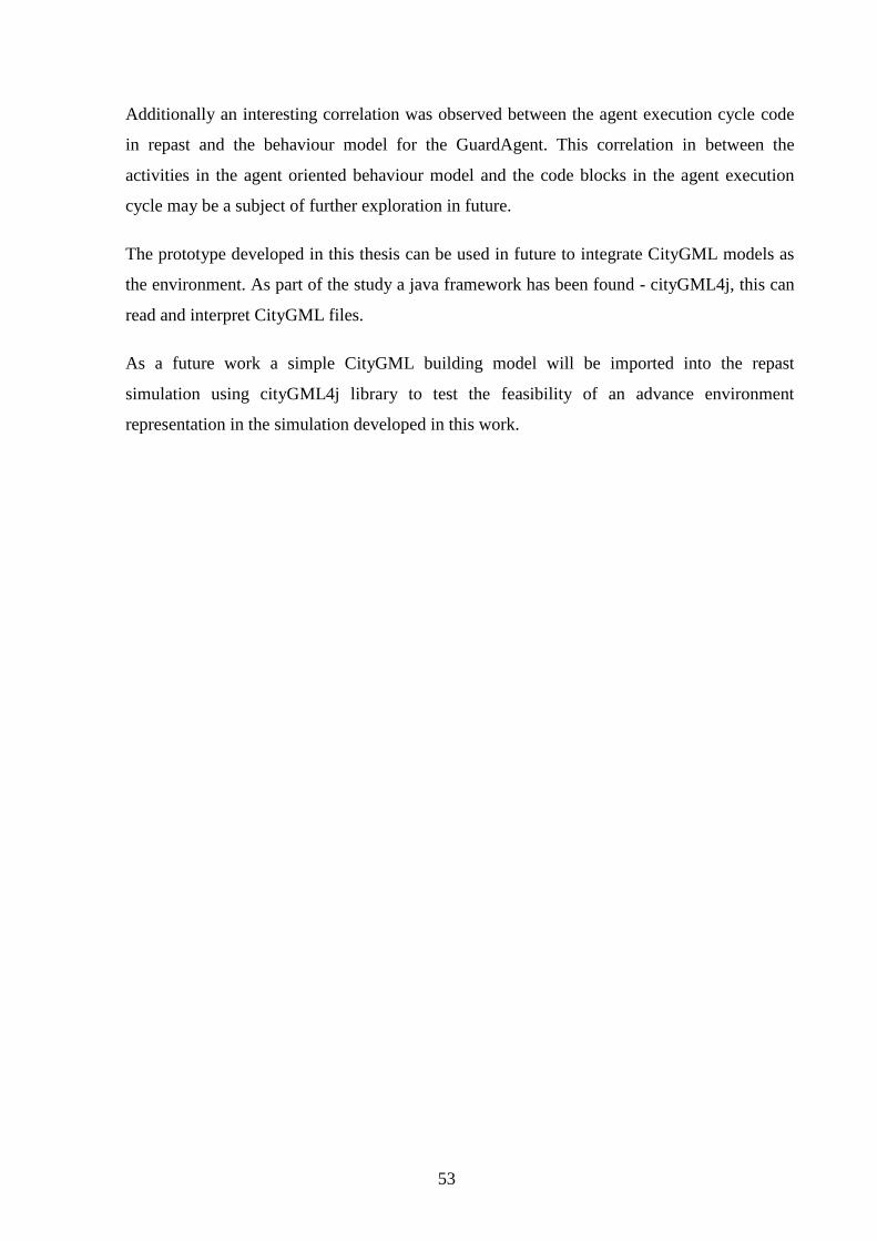
53
Additionally an interesting correlation was observed between the agent execution cycle code
in repast and the behaviour model for the GuardAgent. This correlation in between the
activities in the agent oriented behaviour model and the code blocks in the agent execution
cycle may be a subject of further exploration in future.
The prototype developed in this thesis can be used in future to integrate CityGML models as
the environment. As part of the study a java framework has been found - cityGML4j, this can
read and interpret CityGML files.
As a future work a simple CityGML building model will be imported into the repast
simulation using cityGML4j library to test the feasibility of an advance environment
representation in the simulation developed in this work.
54
Resümee
Füüsilise keskkonna modelleerimine ja simulatsioon kriisihalduse
treeningstsenaariumite jaoks
Magistritöö
Autor: Jishu Guin
Juhendaja: Professor Kuldar Taveter, PhD
Käesolev töö põhineb Tallinna Tehnikaülikoolis tehtud uurimistööl agentorienteeritud
süsteemide välja töötamise kohta linnatingimustes toimuvate operatsioonide
õppestsenaariumite simuleerimiseks. Linnatingimustes toimuvate operatsioonide all
mõeldakse kõiki tegevusi, mida kavandatakse ja viiakse läbi sõjaliste operatsioonide raames
olukorras, kus ülesande täitmine toimub maastikul, kus domineerivad inimese poolt ehitatud
rajatised ja operatsioonis mitteosalejad. Uurimistöös jõutakse järeldusele, et
agentorienteeritud modelleerimisel on potentsiaali aidata lahendada linnakeskkonna
dünaamilisest olemusest tulenevaid probleeme realistlike stsenaariumite kavandamisel
eesmärgiga simuleerida linnatingimustes toimuvaid operatsioone. Uurimistöö teeb ettepaneku
realistlike treeningstsenaariumite arendamiseks inimkäitumise adekvaatse modelleerimise
suunas kasutades agentorienteeritud käitumismudeleid. Niisugustes treeningstsenaariumites
võib tarkvaraagendi asendada reaalse mängijaga. Käesolev uurimistöö arendab seda eesmärki
edasi, rakendades linnatingimustes toimuva operatsiooni ülilihtsustatud näidisstsenaariumit,
kasutades selleks olemasolevat agendipõhist modelleerimistööriista Repast Simphony. See
süsteem simuleerib lihtsat hoonest evakueerimise stsenaariumit. Selle stsenaariumi mõnede
põhiomaduste aluseks on raamtöös kasutatud linnatingimustes toimuva operatsiooni
stsenaarium. Rakendus põhineb platvormist sõltumatutel mudelitel, mis on välja töötatud
raamtöö suuniste alusel.
Selles simulatsioonis keskendutakse peamiselt linnakeskkonnale. Näidisstsenaarium
simuleerib lihtsustatud kujul hoonest evakueerimise operatsiooni. Hoonete keskkonna
modelleerimiseks kasutatakse siseruumide modelleerimise formaalset meetodit, mida
nimetatakse kaalutud siseruumide graafikaks (Weighed Indoor Routing Graph). Selles töös
kirjeldatakse ka kahte ontoloogiat – IFC ja CityGML, mis toetavad linnamudelite
55
simuleerimist. Eesmärgiks on uurida võimalusi kasutada tööstuslikult valmistatud
ontoloogiaid keskkondade modelleerimiseks agendipõhisel simuleerimisel. Tuginedes nende
kahe ontoloogia varem läbi viidud võrdlusuuringutele leiti, et keskkonna modelleerimiseks
agendipõhisel linnatingimustes toimuva operatsiooni simuleerimiseks sobib paremini
CityGML.
Selle uurimistöö täiendamine tulevikus hõlmab esimese kohese sammuna lihtsa ehitusmudeli
kasutamist CityGML-s, et luua selle töö jaoks välja töötatud rakenduse keskkonna prototüüp,
mis annab ülevaate tehnilistest teguritest, mis on seotud ontoloogia integreerimisega süsteemi.
Käesoleva töö edasiarendus võib viia realistlike simulatsioonide arendamisele
treeningstsenaariumite jaoks kasutades cityGML mudeleid.

56
References
Castle, C.J.E., Crooks, A.T. Principles and Concepts of Agent-Based Modelling for
Developing Geospatial Simulations. Working paper, Centre for Advanced Spatial Analysis ,
London: UCL Centre for Advanced Spatial Analysis (CASA), 2006, 1-52.
El-Mekawy, M. “Integrating BIM and GIS for 3D City Modelling: The Case of IFC and
CityGML.” Licentiate thesis, comprehensive summary (Other academic), Department of
Urban Planning and Environment, Royal Institute of Technology (KTH), Stockholm, 2010, 1-
60.
El-Mekawy, M., Östman, A., Hijazi, I. “An Evaluation of IFC-CityGML Unidirectional
Conversion.” International Journal of Advanced Computer Science & Application 3, no. 5
(May 2012).
Environmental Systems Research Institute, Inc. “ESRI Shapefile Technical Description.”
White Paper, Environmental Systems Research Institute, Inc., USA, 1998, 1-28.
Federal Emergency Management Agency (FEMA). Safe Rooms and Shelters: Protecting
People Against Terrorist Attacks. Manual, FEMA 453, 2006.
Giudice, N.A., Walton, L.A., Worboys, M. “The Informatics of Indoor and Outdoor Space: A
Research Agenda.” Proceedings of the 2nd ACM SIGSPATIAL International Workshop on
Indoor Spatial Awareness. New York, 2010. 47-53.
Goetz, M., Zipf, A. “Formal Definition of a User-adaptive and Length-optimal Routing Graph
for Complex Indoor Environments.” Geo-spatial Information Science (Wuhan University) 14,
no. 2 (June 2011): 119-128.
Goetz, M., Zipf, A. “Using Crowdsourced Geodata for Agent-Based Indoor Evacuation
Simulations.” International Journal of Geo-Information (MDPI AG) 1, no. 2 (August 2012):
186-208.
Gutknecht, O., Ferber, J. The MadKit Agent Platform Architecture. Vol. 1887, in Revised
Papers from the International Workshop on Infrastructure for Multi-Agent Systems:
Infrastructure for Agents, Multi-Agent Systems, and Scalable Multi-Agent Systems, 48-55.
Springer-Verlag, 2001.
Hart, M., Vink, N., Buiël, E. An Introduction to Urban Operations. TNO Report, Hague:
TNO Defence, Security and Safety, 2008.
Howe, T.R., Collier, N.T., North, M.J., Parker, M.T., Vos, J.R. “Containing Agents: Contexts,
Projections, and Agents.” In Proceedings of the Agent 2006 Conference on Social Agents:
Results and Prospects, by D.L., Macal, C.M., North, M.J. Sallach, 107-113. Chicago, 2006.
Huget, M.P., Odell, J. “Representing Agent Interaction Protocols with Agent UML.”
Proceedings of the Third International Joint Conference on Autonomous Agents and
Multiagent Systems. IEEE Computer Society, 2004. 1244-1245.
Keil, D., Goldin, D. “Indirect Interaction in Environments for Multi-agent Systems.”
Proceedings of the 2Nd International Conference on Environments for Multi-Agent Systems.
Utrecht: Springer-Verlag, 2006. 68-87.
Konieczny, M., Koźlak, J., Żabińska, M. “Multi-agent Crisis Management in Transport
Domain.” Computational Science – ICCS 2009. Baton Rouge: Springer Berlin Heidelberg,
2009. 855-864.
Laclavík, M., Dlugolinský, Š., Šeleng, M., Kvassay, M., Schneider, B., Bracker, H.,
Wrzeszcz, M., Kitowski, J., Hluchý, L. “Agent-Based Simulation Platform Evaluation in the
Context of Human Behavior Modeling.” Proceedings of the 10th International Conference on
Advanced Agent Technology. Taipei: Springer-Verlag, 2012. 396-410.
57
Luke, S. Multiagent Simulation and the MASON Library. Vers. 17. May 2013.
http://cs.gmu.edu/~eclab/projects/mason/manual.pdf (accessed February 3, 2014).
Luke, S., Cioffi-Revilla, C., Panait, L., Sullivan, K., Balan, G. “MASON: A Multi-Agent
Simulation Environment.” Simulation (Society for Computer Simulation International) 81, no.
7 (July 2005): 517-527.
Macal, C.M., North, M.J. “Agent-based Modeling and Simulation.” Simulation Conference
(WSC), Proceedings of the 2009 Winter. Austin, 2009. 86-98.
Nikolai, C., Madey, G. “Tools of the Trade: A Survey of Various Agent Based Modeling
Platforms.” Journal of Artificial Societies and Social Simulation 12, no. 2 (March 2009).
Cox, S., Daisey, P., Lake, R., Portele, C., Whiteside, A., ed. “OpenGIS® Geography Markup
Language (GML) Implementation Specification.” Vers. 3.1.1. Open Geospatial Consortium. 2
July 2004. http://www.opengeospatial.org/standards/gml (accessed 11 5, 2013).
Pearson, C.M., Clair, J.A. “Reframing Crisis Management.” Academy of Management Review
23, no. 1 (January 1998): 59-76.
Quarantelli, E.L. “Disaster Crisis Management: A Summary of Research Findings.” Journal
of Management Studies 25, no. 4 (July 1988): 373-385.
Quillinan, T.B., Huib Aldewereld, F., Wijngaards, N. “Developing Agent-based
Organizational Models for Crisis Management .” Proceedings of 8th International Conference
on Autonomous Agents and Multiagent Systems (AAMAS 2009) . Budapest : Decker, Sichman,
Sierra and Castelfranchi (eds.) , 2009.
Railsback, S.F., Lytinen, S.L., Jackson, S.K. Agent-based Simulation Platforms: Review and
Development Recommendations. 2006.
http://www.humboldt.edu/ecomodel/documents/ABMPlatformReview.pdf (accessed January
27, 2014).
Repast. “Repast Simphony.” Repast. 18 March 2009.
http://repast.sourceforge.net/docs/Getting%20Started.pdf (accessed February 27, 2014).
Repastcity. “RepastCity3. Introduction to RepastCity3.” Repastcity. 19 January 2012.
https://code.google.com/p/repastcity/wiki/RepastCity3 (accessed January 14, 2013).
Rose, R.A. “Introduction to Geographic Information System.” Harvard College Library: GIS
Tutorials and Exercises. 1 June 2009.
http://hcl.harvard.edu/libraries/maps/gis/IntroToGISmovie-part1.htm (accessed January 16,
2014).
Russell, S., Norvig, P. Artificial Intelligence: A Modern Approach. 3rd Edition. Pearson
Education Ltd., 2009.
Schoenharl, T., Zhai, Z., McCune, R., Pawling, A., Madey, G. “Design and Implementation of
an Agent-Based Simulation for Emergency Response and Crisis Management.” Proceedings
of the 2009 Spring Simulation Multiconference. San Diego: Society for Computer Simulation
International, 2009. 1-12.
Shvartsman, I., Taveter, K., Parmak, M., Meriste, M. “Agent-Oriented Modelling for
Simulation of Complex Environments.” Proceedings of the International Multiconference on
Computer Science and Information Technology. Wisla: IEEE, 2010. 209-216.
Steinberg, S.J., Steinberg, S.L. Geographic Information Systems for the Social Sciences:
Investigating Space and Place. Vol. 1. 1 vols. SAGE Publications, 2006.
Sterling, L.S., Taveter, K. The Art of Agent-Oriented Modeling. The MIT Press, 2009.
Sutton, T., Dassau, O., Sutton, M. A Gentle Introduction to GIS. Eastern Cape: Spatial
Planning and Information, Department of Land Affairs, 2009.
Winikoff, M. “Towards Making Agent UML Practical: A Textual Notation and a Tool.”
Proceedings of the Fifth International Conference on Quality Software . IEEE Computer
Society, 2005. 401-412.

58
Related Documents