Modelling and simulation of new generation powerful gyrotrons for the fusion research This article has been downloaded from IOPscience. Please scroll down to see the full text article. 2007 J. Phys.: Conf. Ser. 63 012003 (http://iopscience.iop.org/1742-6596/63/1/012003) Download details: IP Address: 195.96.224.8 The article was downloaded on 08/03/2011 at 08:45 Please note that terms and conditions apply. View the table of contents for this issue, or go to the journal homepage for more Home Search Collections Journals About Contact us My IOPscience

Welcome message from author
This document is posted to help you gain knowledge. Please leave a comment to let me know what you think about it! Share it to your friends and learn new things together.
Transcript
Modelling and simulation of new generation powerful gyrotrons for the fusion research
This article has been downloaded from IOPscience. Please scroll down to see the full text article.
2007 J. Phys.: Conf. Ser. 63 012003
(http://iopscience.iop.org/1742-6596/63/1/012003)
Download details:
IP Address: 195.96.224.8
The article was downloaded on 08/03/2011 at 08:45
Please note that terms and conditions apply.
View the table of contents for this issue, or go to the journal homepage for more
Home Search Collections Journals About Contact us My IOPscience
Modelling and simulation of new generation powerful
gyrotrons for the fusion research
S Sabchevski1 and I Zhelyazkov
2
1Institute of Electronics, Bulgarian Academy of Sciences, BG-1784 Sofia, Bulgaria
2Faculty of Physics, Sofia University, BG-1164 Sofia, Bulgaria
2E-mail: [email protected]
Abstract. One of the important issues related with the cyclotron resonance heating (CRH) and current drive of fusion plasmas in thermonuclear reactors (tokamaks and stellarators) is the development of multi-megawatt class gyrotrons. There are generally three stages of the implementation of that task, notably (i) elaborating a novel generation of software tools for the physical modelling and simulation of such kind of gyrotrons, (ii) their computer aided design (CAD) and construction on the basis of the simulation’s results, and finally, (iii) gyrotrons’ testing in real experimental conditions. This tutorial paper concerns the first item – the development of software tools. In co-operation with the Institute for Pulsed Power and
Microwave Technology at the Forschungszentrum Karlsruhe, Germany, and Centre de
Recherches en Physique des Plasmas at École Polytechnique Fédérale de Lausanne, Switzerland, we work on the conceptual design of the software tools under development. The basic conclusions are that the numerical codes for gyrotrons’ modelling should possess the following essential characteristics: (a) portability, (b) extensibility, (c) to be oriented toward the solution of practical problems (i.e., elaborating of computer programs that can be used in the design process), (d) to be based on self-consistent 3D physical models, which take into account the departure from axial symmetry, and (e) ability to simulate time dependent processes (electrostatic PIC simulation) alongside with a trajectory analysis (ray tracing simulation). Here, we discuss how various existing numerical codes have to be improved and implemented via the advanced programming technologies for state-of-the-art computer systems including clusters, grid, parallel platforms, and supercomputers.
1. Motivation and introduction
The goal of fusion research is the “burning plasma” – fully ionized gas self-sustained in an extreme state by power released from fusion reactions of its atomic nuclei. The burning plasma would then provide a new powerful, clean and safe source of energy. To achieve this, one needs to overcome two major challenges. First, to ignite the plasma, temperatures in the order of hundreds of millions of degrees centigrade must be reached i.e. the plasma must be heated sufficiently. The second, a more difficult challenge, is to sustain the plasma at these temperatures by confining and controlling it in order to maintain its density and ensure that it does not suffer excessive heat losses.
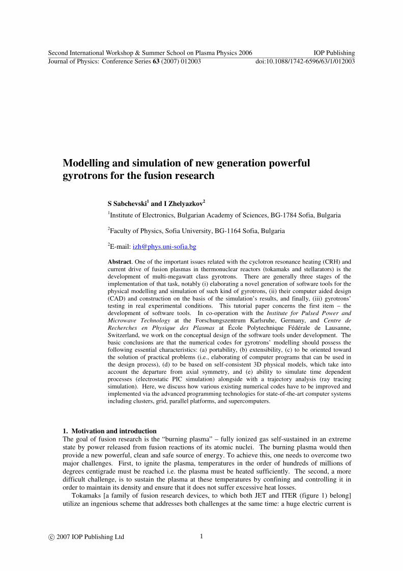
Tokamaks [a family of fusion research devices, to which both JET and ITER (figure 1) belong] utilize an ingenious scheme that addresses both challenges at the same time: a huge electric current is
Second International Workshop & Summer School on Plasma Physics 2006 IOP PublishingJournal of Physics: Conference Series 63 (2007) 012003 doi:10.1088/1742-6596/63/1/012003
c© 2007 IOP Publishing Ltd 1
induced in the plasma to heat it and to complement the confining magnetic field. The electric current produces heat thanks to the well-known Joule effect.
Figure 1. Scale model of ITER. The tokamak concept is a breakthrough in plasma research, but not a complete solution. At
millions of degrees and above, plasma is conducting electricity far too well, with very little resistance – which also means with not enough heat produced by the Joule effect. The unit of electric resistance is the Ohm, so plasma physicists usually say ‘Ohmic heating is ineffective at high temperatures’ where the word ‘high’ refers to the hundreds of millions of degrees required for burning plasmas. In order to attain the target temperatures some sort of additional heating is required to supplement the Ohmic
heating (as a matter of fact, eventually the ‘additional heating’ plays a dominant role). Neutral particle beams (NB Injection Heating) and resonant electromagnetic waves (RF Heating) can do this job. Furthermore, tokamaks cannot maintain a continuous electrical current in the plasma and this limits the concept of complementing the magnetic field. Tokamaks have a transformer-like electrical setup, with plasma that acts as a single secondary loop – and no transformer can provide continuous direct electric current in its secondary circuit. An additional current drive is to be provided if we wish to confine burning plasma continuously. Electromagnetic wave current drive offers a possible solution. Among the resonant waves absorption methods that of the electron cyclotron heating (ECH) turns out to be very important and locally controlled. However, in order to absorb a huge amount of energy (of order of megawatts) one needs powerful generators of electromagnetic waves at frequencies between 110–170 GHz. Such devices are the so called gyrotrons. In the next sections of the paper we present the basic principles of action of a gyrotron as well as the methods of its modelling and numerical simulation.
2. Operating principles of a gyrotron
A gyrotron, also called electron cyclotron maser (ECM), is a microwave tube designed to produce coherent radio-frequency waves of high power and high intensity. The waves are generated by an
ensemble of gyrating electrons (from here comes the name of these devices) which execute helical motion in a strong magnetic field. Because the electrons are bunched in phase due to relativistic effects and thus are synchronized with the wave, the radiation is coherent. The wave energy is extracted from electrons which have been accelerated with a magnetron injection gun (MIG) (figure 2). The wave is generated in a specially designed interaction cavity (resonator) which can sustain oscillations having desired frequency and mode structure. In modern gyrotrons the specific operating mode in the resonator is converted by a mode converter (via phase correcting mirrors) into a Gaussian
Second International Workshop & Summer School on Plasma Physics 2006 IOP PublishingJournal of Physics: Conference Series 63 (2007) 012003 doi:10.1088/1742-6596/63/1/012003
2
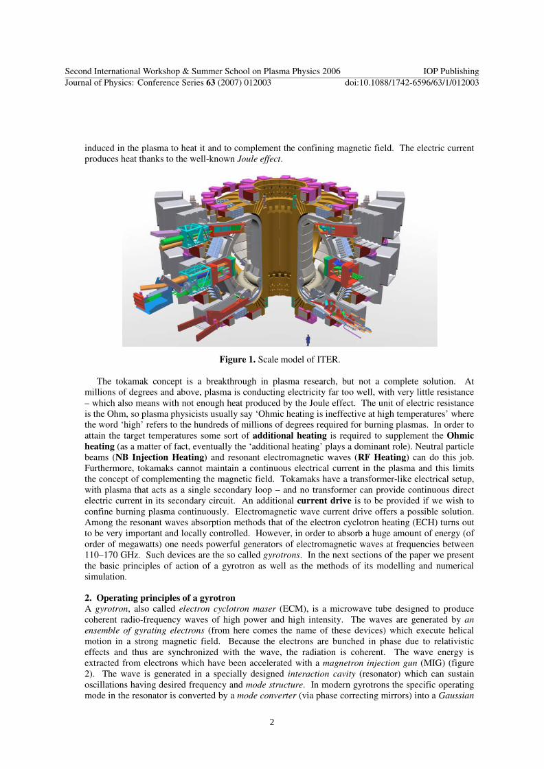
beam which is directed by means of special mirrors out of the gyrotron through a diamond window. The decelerated electron beam, instead, is separated from the wave and dumped onto a collector where its residual energy is dissipated.
Figure 2. Schematic of a powerful gyrotron.
The electron beam formed in MIG has tubular cylindrical shape with thickness of order of electron
Larmor diameter. The hollow beam consists of continuous totality of Larmor tubes that are uniformly
distributed by azimuthal angle. The electron beam radius, R, should be optimal from the point of view of interaction with the operating cavity mode.
3. Basic equations and relations
3.1. Interaction between electrons and electromagnetic fields
Let us first recall that the motion of an electron in electric field E and magnetic field B is governed by the Lorentz force equation
)(d
dBvE
p×+−= e
t, (1)
where p is the momentum of the electron with velocity v, and electric charge e− . In the guiding
center approximation valid for sufficiently homogeneous fields the particle motion consists of the motion of the guiding center along a magnetic field line and the gyration around the guiding center at the electron cyclotron frequency
erel
cm
eB
γω = . (2)
Second International Workshop & Summer School on Plasma Physics 2006 IOP PublishingJournal of Physics: Conference Series 63 (2007) 012003 doi:10.1088/1742-6596/63/1/012003
3
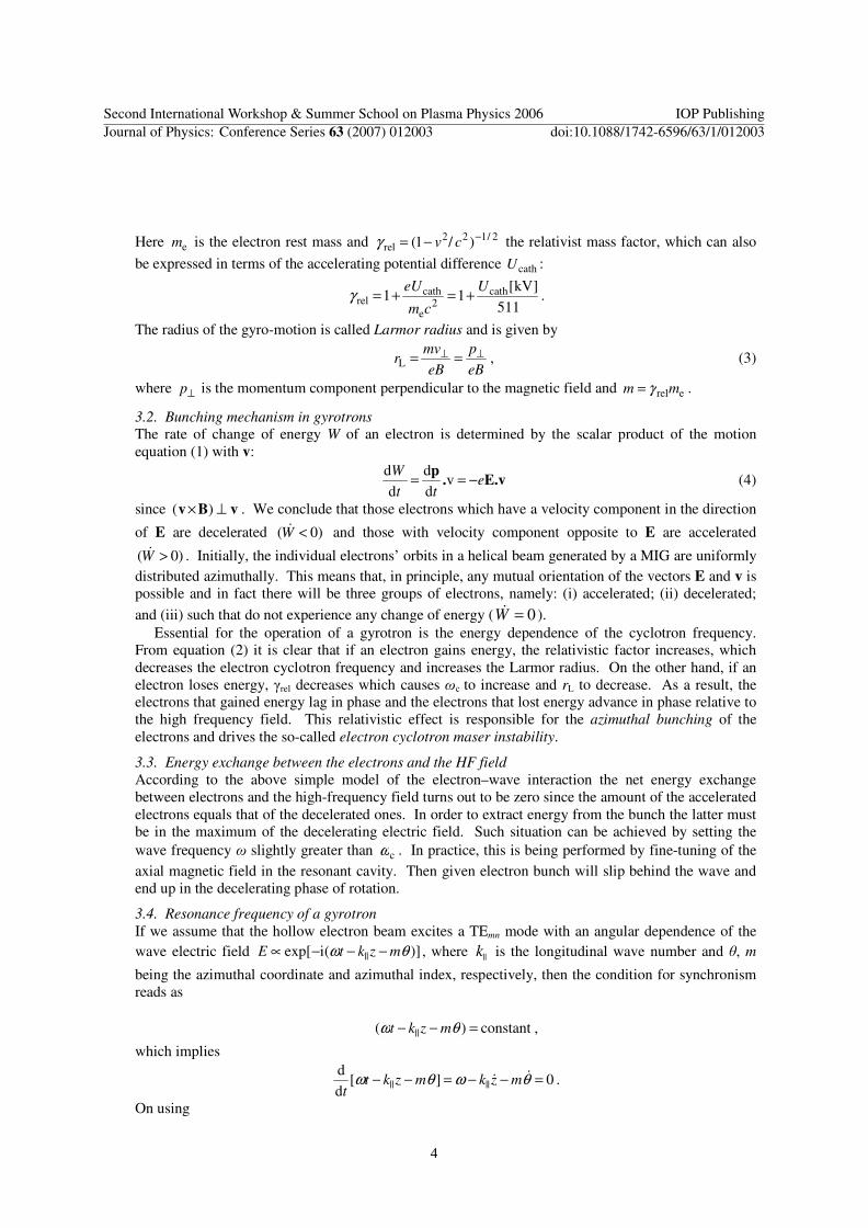
Here em is the electron rest mass and 2/122rel )/1( −−= cvγ the relativist mass factor, which can also
be expressed in terms of the accelerating potential difference cathU :
511
]kV[11 cath
2e
cathrel
U
cm
eU+=+=γ .
The radius of the gyro-motion is called Larmor radius and is given by
eB
p
eB
mvr ⊥⊥ ==L , (3)
where ⊥p is the momentum component perpendicular to the magnetic field and erelmm γ= .
3.2. Bunching mechanism in gyrotrons
The rate of change of energy W of an electron is determined by the scalar product of the motion equation (1) with v:
E.v.p
ett
W−== v
d
d
d
d (4)
since vBv ⊥× )( . We conclude that those electrons which have a velocity component in the direction
of E are decelerated )0( <W& and those with velocity component opposite to E are accelerated
)0( >W& . Initially, the individual electrons’ orbits in a helical beam generated by a MIG are uniformly distributed azimuthally. This means that, in principle, any mutual orientation of the vectors E and v is possible and in fact there will be three groups of electrons, namely: (i) accelerated; (ii) decelerated;
and (iii) such that do not experience any change of energy ( 0=W& ). Essential for the operation of a gyrotron is the energy dependence of the cyclotron frequency.
From equation (2) it is clear that if an electron gains energy, the relativistic factor increases, which decreases the electron cyclotron frequency and increases the Larmor radius. On the other hand, if an electron loses energy, γrel decreases which causes ωc to increase and rL to decrease. As a result, the electrons that gained energy lag in phase and the electrons that lost energy advance in phase relative to the high frequency field. This relativistic effect is responsible for the azimuthal bunching of the electrons and drives the so-called electron cyclotron maser instability.
3.3. Energy exchange between the electrons and the HF field
According to the above simple model of the electron–wave interaction the net energy exchange between electrons and the high-frequency field turns out to be zero since the amount of the accelerated electrons equals that of the decelerated ones. In order to extract energy from the bunch the latter must be in the maximum of the decelerating electric field. Such situation can be achieved by setting the wave frequency ω slightly greater than cω . In practice, this is being performed by fine-tuning of the axial magnetic field in the resonant cavity. Then given electron bunch will slip behind the wave and end up in the decelerating phase of rotation.
3.4. Resonance frequency of a gyrotron
If we assume that the hollow electron beam excites a TEmn mode with an angular dependence of the wave electric field )](iexp[ || θω mzktE −−−∝ , where ||k is the longitudinal wave number and θ, m
being the azimuthal coordinate and azimuthal index, respectively, then the condition for synchronism reads as
constant)( || =−− θω mzkt ,
which implies
0][d
d|||| =−−=−− θωθω && mzkmzkt
t.
On using
Second International Workshop & Summer School on Plasma Physics 2006 IOP PublishingJournal of Physics: Conference Series 63 (2007) 012003 doi:10.1088/1742-6596/63/1/012003
4
cωθ =& , ||vz =&
(where ||vz =& is the axial velocity of the electron), one gets the so called beam–wave resonance line:
||||c vkm += ωω . (5)
The integer parameter m has a meaning of a harmonic number. Therefore, the gyrotrons operate on frequencies close to the electron cyclotron frequency or its harmonics. On the other hand, the dispersion relation of the waveguide mode is:
2222||
2ckck ⊥+=ω . (6)
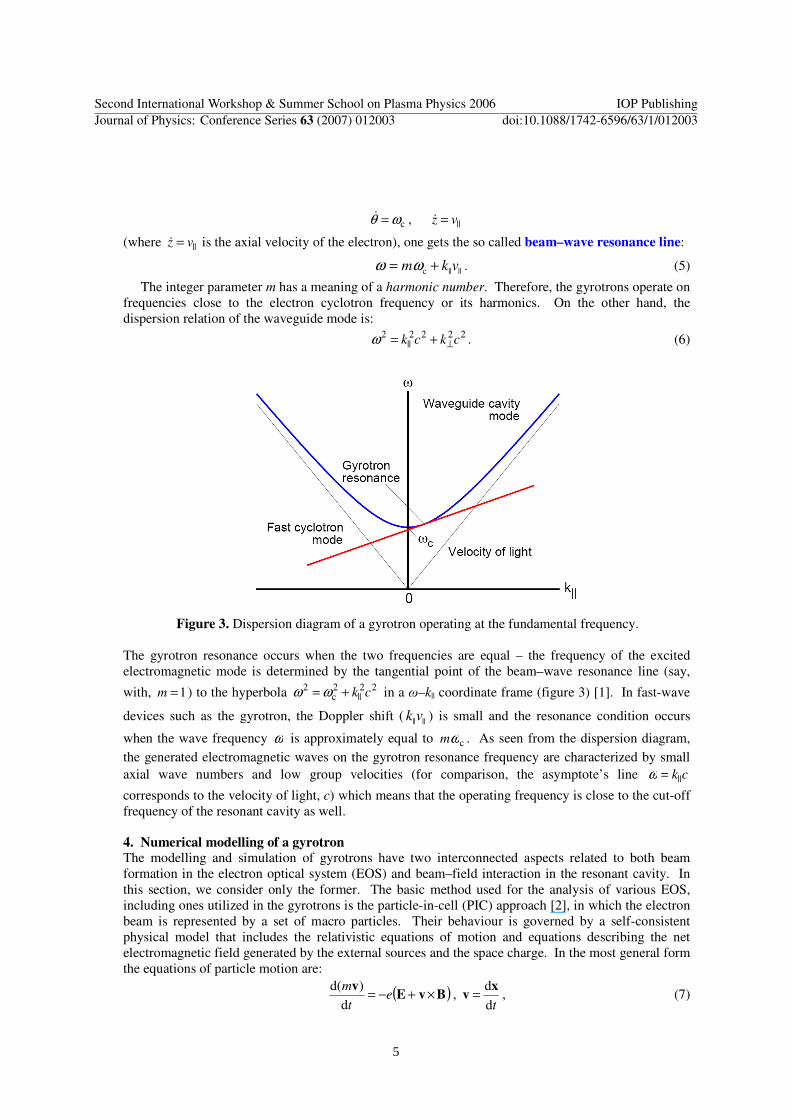
Figure 3. Dispersion diagram of a gyrotron operating at the fundamental frequency.
The gyrotron resonance occurs when the two frequencies are equal – the frequency of the excited electromagnetic mode is determined by the tangential point of the beam–wave resonance line (say,
with, 1=m ) to the hyperbola 22||
2c
2 ck+= ωω in a ω–k|| coordinate frame (figure 3) [1]. In fast-wave
devices such as the gyrotron, the Doppler shift ( ||||vk ) is small and the resonance condition occurs
when the wave frequency ω is approximately equal to cωm . As seen from the dispersion diagram, the generated electromagnetic waves on the gyrotron resonance frequency are characterized by small axial wave numbers and low group velocities (for comparison, the asymptote’s line ck||=ω
corresponds to the velocity of light, c) which means that the operating frequency is close to the cut-off frequency of the resonant cavity as well.
4. Numerical modelling of a gyrotron The modelling and simulation of gyrotrons have two interconnected aspects related to both beam formation in the electron optical system (EOS) and beam–field interaction in the resonant cavity. In this section, we consider only the former. The basic method used for the analysis of various EOS, including ones utilized in the gyrotrons is the particle-in-cell (PIC) approach [2], in which the electron beam is represented by a set of macro particles. Their behaviour is governed by a self-consistent physical model that includes the relativistic equations of motion and equations describing the net electromagnetic field generated by the external sources and the space charge. In the most general form the equations of particle motion are:
( )BvEv
×+−= et
m
d
)d(,
td
dxv = , (7)
Second International Workshop & Summer School on Plasma Physics 2006 IOP PublishingJournal of Physics: Conference Series 63 (2007) 012003 doi:10.1088/1742-6596/63/1/012003
5
where ),(),,( tt xBBxEE == . In electrostatic approximation, the electric field is φ−∇=E , where
φ =φ (x) is the scalar electric potential and B is a sum of the external static magnetic field B0 and the self-magnetic field of the electron beam Bs. The potential distribution φ is calculated solving an appropriate boundary value problem, i.e. Poisson;s equation
02 ερφ =∇ , (8)
where 0ε is the vacuum permittivity on a domain Ω bounded by ∂Ω with space charge density
)(xρρ = as a source term and corresponding Dirichlet and Neumann boundary conditions
iU=)(xφ for iEΩ∂∈x , e,...,2,1 Ni = and 0/)( =∂∂ nxφ for iSΩ∂∈x , s,...,2,1 Ni = .
Here Ui are the potentials of Ne electrodes specified by their surfaces ∂ΩEi and ∂/∂n is differentiation in the direction of the outward normal to Ns closing surfaces ∂ΩSi. From the topology of the computational domain Ω in a real EOS it is clear that ∂Ω = ∂ΩS ∪ ∂ΩE where ∂ΩE = ∂ΩE1 ∪ ∂ΩE2 ∪ …∂ΩENe and ∂ΩS = ∂ΩS1 ∪ ∂ΩS2 ∪ …∂ΩSNs.
The magnetic field, )(xB , can be computed from a set of coils using the Biot–Savar law or integral relations based on it.
There are several techniques used for integration of the equations of motion (7), namely (i) Newton scheme; (ii) Boris–Buneman algorithm; (iii) Leapfrog scheme; (iv) Runge–Kutta method; (v) Canonical method etc. Among them the Boris–Buneman algorithm is known as the most appropriate for tracing charged particles in electromagnetic fields due to its numerical efficiency and accuracy. At each )1( +n th time step, t∆ , this scheme starts performing one half of the electric field acceleration
Euu += n , (9) followed by a Larmor rotation in the magnetic field
2
1
)(2
B
BBuuuu
+
××++= , (10)
and completed by the second half of the acceleration
Euu +=+1n , (11)
where nnn vu γ= , 22 /1/1 cnn v−=γ , ( )EE e2/ mte∆= , ( )BB nmte γe2/∆= . Finally both the
velocities and positions of the particles are updated using the relations
22111 /1/ cnnn +++ += uuv , tnnn ∆+= ++ 11 vxx . (12)
An indispensable part of this physical model includes relations that specify the initial conditions such as emitted current, energy spectrum and angular distribution of the electrons extracted from the cathode
EE2121 ),,...,,,,...,,),(),(,( Ω∂∈Ψ=Ψ xxBxEx NL PPPϕϕϕ , (13)
where the functions Lϕϕϕ ,...,, 21 and parameters NPPP ,...,, 21 describing initial conditions (e.g. cathode
temperature, surface roughness) are defined on the emitting surface EEΩ∂ . There are two most commonly used methods for the solution of the boundary value problem in the
PIC codes – Finite Difference Method (FDM) and Finite Elements Method (FEM). The FDM uses structured grid for discretization of the computational domain. Such a mesh offers an easy and economical way for particles’ localization and pushing but can not represent the boundary (and hence the boundary and initial conditions) with a sufficient accuracy. The FEM, on the contrary, utilizes unstructured mesh and allows one to treat complicated configurations. Unfortunately, the particle localization and tracing on such meshes is algorithmically more complicated and requires more computational resources.
Second International Workshop & Summer School on Plasma Physics 2006 IOP PublishingJournal of Physics: Conference Series 63 (2007) 012003 doi:10.1088/1742-6596/63/1/012003
6
While the physical model outlined above is still in a process of implementation, we are using some other codes available to us in order to study their limitations that should be avoided in the new generation of software tools.
Most of the ray-tracing (trajectory analysis) codes use the FDM to calculate self-consistently the electrostatic field in a 2D domain which is usually a meridional cross-section of an axially symmetric volume. This applies also to the famous program EGUN [3] which is designed to compute trajectories of charged particles in electrostatic and magnetostatic fields, including the effects of space charge and self-magnetic fields. Starting options include Child's law conditions on cathodes of various shapes, as well as user specified initial conditions. Either rectangular or cylindrical symmetry may be used. Magnetic fields are to be specified externally by the user, employing one of the several methods which include data from another program or arbitrary configurations of coils. Particle dynamics is analyzed in a five dimensional phase space (three velocity components and two coordinates). Since usually the dimension of the physical model is defined as a half of that of the underlying phase space one could classify EGUN as a 2-1/2D code.
Some of the most prominent 2-l/2D codes for electron gun and beam tunnel simulations are DAFNE [4] (Centre de Recherches en Physique des Plasmas, École Politechnique Fédérale de Lausanne) and ESRAY [5] (Institute for Pulsed Power and Microwave Technology, Forschungs-zentrum Karlsruhe), as well as EPOSR [6], EPOS-V [7] (Institute of Applied Physics, Russian Academy of Sciences, Nizhny Novgorod), MAGY [8] (Institute for Plasma Research, University of Maryland, College Park) and GUN-MIG/CUSP [9]. Irrespective of their different implementations the algorithms of the aforementioned codes are basically the same and include the following basic steps: (i) Input of initial data and parameters as well as logical keys specifying the content of numerical experiments and output information. (ii) Analysis of the geometry of the gun, boundary conditions and generation of an appropriate mesh system. Once the geometry has been analyzed, the program proceeds with the main iterative portion of the code responsible for a self-consistent solution of the problem [steps (iii)–(vii)]. (iii) Solution of the Laplace's equation by one or another numerical method (FDM, FEM and so on). (iv) Computation of the extracted current density in each element of the annular emitting ring. (v) A finite number of electron trajectories, each associated with a definite current density is then traced trough the obtained electric field integrating the equations of motion. (vi) Computation of the space charge density distribution by the PIC method using an appropriate algorithm (e.g. the Area Weighted Algorithm) for allocating the charge to the mesh points. (vii) Solution of Poisson's equation with the space charge distribution obtained during the previous step. Then steps (iv)–(vii) are repeated until a self-consistent solution is obtained. (viii) The final step of any numerical experiment includes processing of the obtained data as well as output of the results.
As an illustration, we present here a few graphical results from computer simulation of MIGs. The first example (figure 4) shows a typical result from the trajectory analysis of a conventional MIG performed by using the EGUN code. Next illustrations, presented in figures 5–8, demonstrate the visualization capabilities of the ESRAY package. They are obtained from the numerical experiments carried out in order to simulate a coaxial MIG of the 170 GHz-2 MW gyrotron at the Forshungs-zentrum Karlsruhe (figures 4–8).
The plot in figure 4 visualizes very clearly the emitting ring of the cathode as well as the trajectories of the emitted electrons. In figure 5 one can see the grid structure of the so called body fitted mesh which smoothly changes and adapts to the shape of the boundary of the electrodes in the gun. Next figure 6 yields, similarly as in figure 4, the electron trajectories of the hollow electron beam, while figure 7 picks the variations of the magnetic field induction inside the gun. Figure 8 yields both the radial and longitudinal distribution of the magnetic field created by various coils. It is worth mentioning that the large magnetic field in the beam tunnel region is sustained by superconducting coils (see figure 2) cooled by liquid helium – the magnetic field induction there is larger than 6 T!
Second International Workshop & Summer School on Plasma Physics 2006 IOP PublishingJournal of Physics: Conference Series 63 (2007) 012003 doi:10.1088/1742-6596/63/1/012003
7
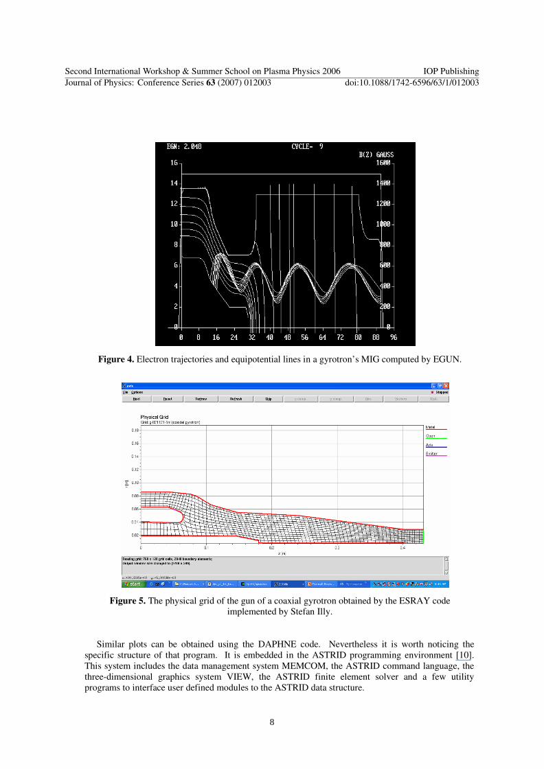
Figure 4. Electron trajectories and equipotential lines in a gyrotron’s MIG computed by EGUN.
Figure 5. The physical grid of the gun of a coaxial gyrotron obtained by the ESRAY code implemented by Stefan Illy.
Similar plots can be obtained using the DAPHNE code. Nevertheless it is worth noticing the
specific structure of that program. It is embedded in the ASTRID programming environment [10]. This system includes the data management system MEMCOM, the ASTRID command language, the three-dimensional graphics system VIEW, the ASTRID finite element solver and a few utility programs to interface user defined modules to the ASTRID data structure.
Second International Workshop & Summer School on Plasma Physics 2006 IOP PublishingJournal of Physics: Conference Series 63 (2007) 012003 doi:10.1088/1742-6596/63/1/012003
8
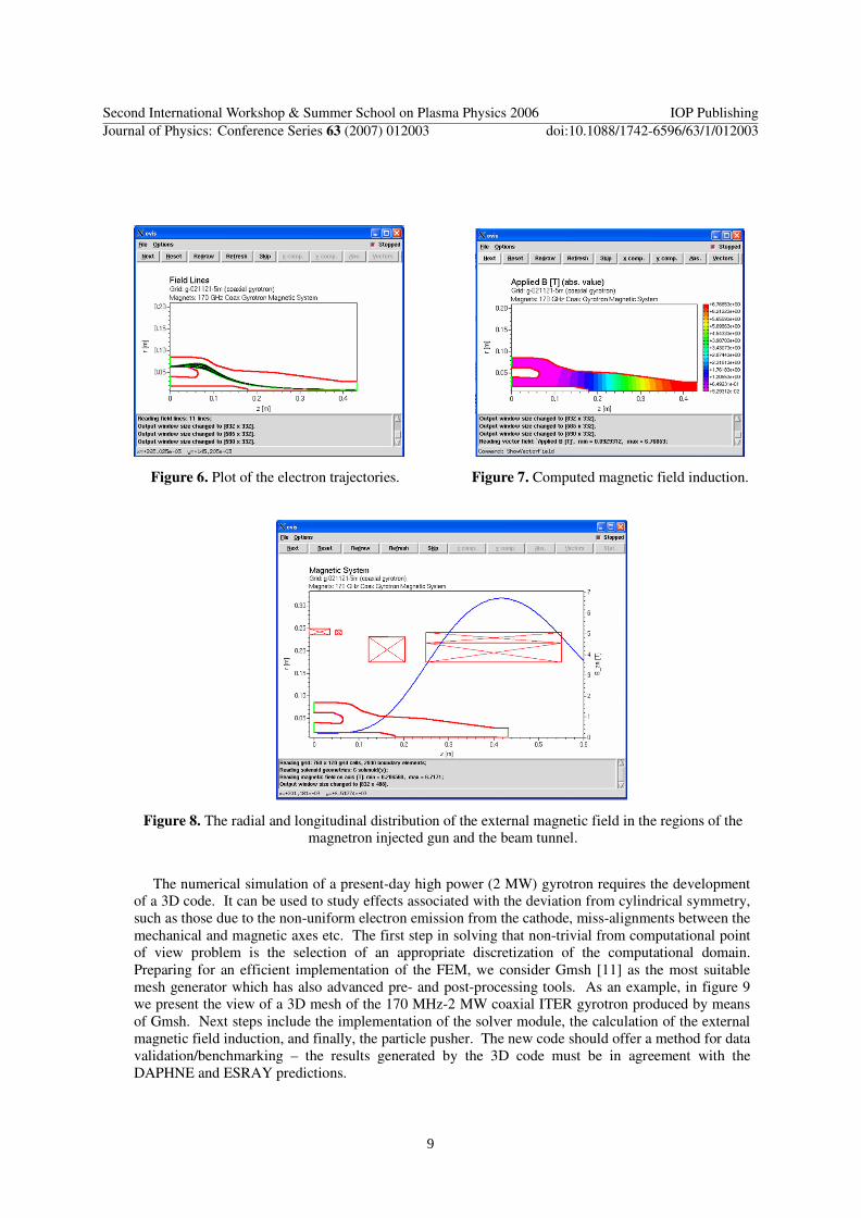
Figure 6. Plot of the electron trajectories. Figure 7. Computed magnetic field induction.
Figure 8. The radial and longitudinal distribution of the external magnetic field in the regions of the magnetron injected gun and the beam tunnel.
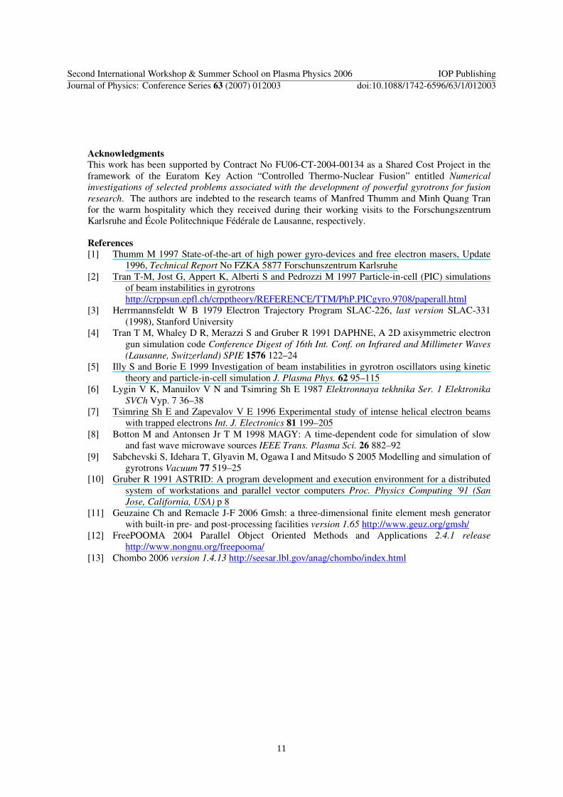
The numerical simulation of a present-day high power (2 MW) gyrotron requires the development
of a 3D code. It can be used to study effects associated with the deviation from cylindrical symmetry, such as those due to the non-uniform electron emission from the cathode, miss-alignments between the mechanical and magnetic axes etc. The first step in solving that non-trivial from computational point of view problem is the selection of an appropriate discretization of the computational domain. Preparing for an efficient implementation of the FEM, we consider Gmsh [11] as the most suitable mesh generator which has also advanced pre- and post-processing tools. As an example, in figure 9 we present the view of a 3D mesh of the 170 MHz-2 MW coaxial ITER gyrotron produced by means of Gmsh. Next steps include the implementation of the solver module, the calculation of the external magnetic field induction, and finally, the particle pusher. The new code should offer a method for data validation/benchmarking – the results generated by the 3D code must be in agreement with the DAPHNE and ESRAY predictions.
Second International Workshop & Summer School on Plasma Physics 2006 IOP PublishingJournal of Physics: Conference Series 63 (2007) 012003 doi:10.1088/1742-6596/63/1/012003
9
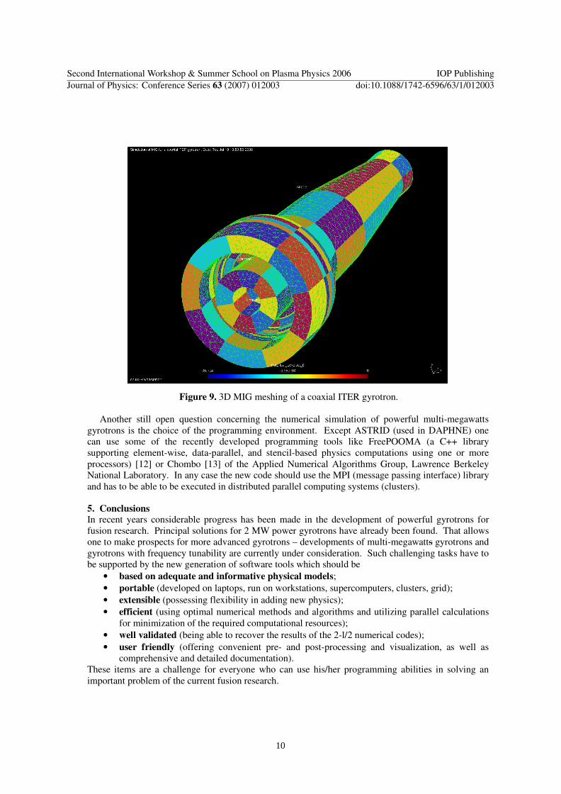
Figure 9. 3D MIG meshing of a coaxial ITER gyrotron.
Another still open question concerning the numerical simulation of powerful multi-megawatts gyrotrons is the choice of the programming environment. Except ASTRID (used in DAPHNE) one can use some of the recently developed programming tools like FreePOOMA (a C++ library supporting element-wise, data-parallel, and stencil-based physics computations using one or more processors) [12] or Chombo [13] of the Applied Numerical Algorithms Group, Lawrence Berkeley National Laboratory. In any case the new code should use the MPI (message passing interface) library and has to be able to be executed in distributed parallel computing systems (clusters).
5. Conclusions
In recent years considerable progress has been made in the development of powerful gyrotrons for fusion research. Principal solutions for 2 MW power gyrotrons have already been found. That allows one to make prospects for more advanced gyrotrons – developments of multi-megawatts gyrotrons and gyrotrons with frequency tunability are currently under consideration. Such challenging tasks have to be supported by the new generation of software tools which should be
• based on adequate and informative physical models; • portable (developed on laptops, run on workstations, supercomputers, clusters, grid); • extensible (possessing flexibility in adding new physics); • efficient (using optimal numerical methods and algorithms and utilizing parallel calculations
for minimization of the required computational resources); • well validated (being able to recover the results of the 2-l/2 numerical codes); • user friendly (offering convenient pre- and post-processing and visualization, as well as
comprehensive and detailed documentation). These items are a challenge for everyone who can use his/her programming abilities in solving an important problem of the current fusion research.
Second International Workshop & Summer School on Plasma Physics 2006 IOP PublishingJournal of Physics: Conference Series 63 (2007) 012003 doi:10.1088/1742-6596/63/1/012003
10
Acknowledgments This work has been supported by Contract No FU06-CT-2004-00134 as a Shared Cost Project in the framework of the Euratom Key Action “Controlled Thermo-Nuclear Fusion” entitled Numerical
investigations of selected problems associated with the development of powerful gyrotrons for fusion
research. The authors are indebted to the research teams of Manfred Thumm and Minh Quang Tran for the warm hospitality which they received during their working visits to the Forschungszentrum Karlsruhe and École Politechnique Fédérale de Lausanne, respectively.
References
[1] Thumm M 1997 State-of-the-art of high power gyro-devices and free electron masers, Update 1996, Technical Report No FZKA 5877 Forschunszentrum Karlsruhe
[2] Tran T-M, Jost G, Appert K, Alberti S and Pedrozzi M 1997 Particle-in-cell (PIC) simulations of beam instabilities in gyrotrons
http://crppsun.epfl.ch/crpptheory/REFERENCE/TTM/PhP.PICgyro.9708/paperall.html [3] Herrmannsfeldt W B 1979 Electron Trajectory Program SLAC-226, last version SLAC-331
(1998), Stanford University [4] Tran T M, Whaley D R, Merazzi S and Gruber R 1991 DAPHNE, A 2D axisymmetric electron
gun simulation code Conference Digest of 16th Int. Conf. on Infrared and Millimeter Waves (Lausanne, Switzerland) SPIE 1576 122–24
[5] Illy S and Borie E 1999 Investigation of beam instabilities in gyrotron oscillators using kinetic theory and particle-in-cell simulation J. Plasma Phys. 62 95–115
[6] Lygin V K, Manuilov V N and Tsimring Sh E 1987 Elektronnaya tekhnika Ser. 1 Elektronika
SVCh Vyp. 7 36–38 [7] Tsimring Sh E and Zapevalov V E 1996 Experimental study of intense helical electron beams
with trapped electrons Int. J. Electronics 81 199–205 [8] Botton M and Antonsen Jr T M 1998 MAGY: A time-dependent code for simulation of slow
and fast wave microwave sources IEEE Trans. Plasma Sci. 26 882–92 [9] Sabchevski S, Idehara T, Glyavin M, Ogawa I and Mitsudo S 2005 Modelling and simulation of
gyrotrons Vacuum 77 519–25 [10] Gruber R 1991 ASTRID: A program development and execution environment for a distributed
system of workstations and parallel vector computers Proc. Physics Computing '91 (San Jose, California, USA) p 8
[11] Geuzaine Ch and Remacle J-F 2006 Gmsh: a three-dimensional finite element mesh generator with built-in pre- and post-processing facilities version 1.65 http://www.geuz.org/gmsh/
[12] FreePOOMA 2004 Parallel Object Oriented Methods and Applications 2.4.1 release http://www.nongnu.org/freepooma/
[13] Chombo 2006 version 1.4.13 http://seesar.lbl.gov/anag/chombo/index.html
Second International Workshop & Summer School on Plasma Physics 2006 IOP PublishingJournal of Physics: Conference Series 63 (2007) 012003 doi:10.1088/1742-6596/63/1/012003
11
Related Documents