Departamento de autom ´ atica, ingenier ´ ıa electr ´ onica e inform ´ atica industrial Escuela T ´ ecnica Superior de Ingenieros Industriales Centro de Electr ´ onica Industrial Modelling and Control of Stepper Motors for High Accuracy Positioning Systems Used in Radioactive Environments Autor: Ricardo Picatoste Ruilope Ingeniero en Autom´atica y Electr´onica Industrial por la Universidad Polit´ ecnica de Madrid Directores: Jes´ us ´ Angel Oliver Ram´ ırez Doctor Ingeniero Industrial por la Universidad Polit´ ecnica de Madrid Alessandro Masi Doctor en Ingenier´ ıa de Control e Inform´ atica por la Universit`a degli Studi di Napoli Federico II 2014

Welcome message from author
This document is posted to help you gain knowledge. Please leave a comment to let me know what you think about it! Share it to your friends and learn new things together.
Transcript
Departamento de automatica, ingenierıa electronica e
informatica industrial
Escuela Tecnica Superior de Ingenieros Industriales
Centro de Electronica Industrial
Modelling and Control of
Stepper Motors for High
Accuracy Positioning Systems
Used in Radioactive
Environments
Autor:
Ricardo Picatoste Ruilope
Ingeniero en Automatica y Electronica Industrial por la Universidad Politecnica
de Madrid
Directores:
Jesus Angel Oliver Ramırez
Doctor Ingeniero Industrial por la Universidad Politecnica de Madrid
Alessandro Masi
Doctor en Ingenierıa de Control e Informatica por la Universita degli Studi di
Napoli Federico II
2014

Tribunal
Tribunal nombrado por el Mgfco. y Excmo. Sr. Rector de la Universidad
Politecnica de Madrid, el dıa de de 2014.
Presidente: Prof. Jose Antonio Cobos Marquez, Universidad Politecnica
de Madrid
Vocales: Dr. Mark Butcher, CERN
Prof. Marco Storace, Universidad de Genova
Prof. Antonio Lazaro, Universidad Carlos III de Madrid
Secretario: Prof. Pedro Alou Cervera, Universidad Politecnica de Madrid
Suplentes: Pablo Zumel Vaquero, Universidad Carlos III de Madrid
Prof. Jesus Acero Acero, Universidad de Zaragoza
Realizado el acto de lectura y defensa de la Tesis el dıa de de
2014 en la Escuela Tecnica Superior de Ingenieros Industriales de la Universi-
dad Politecnica de Madrid.
Calificacion:
EL PRESIDENTE LOS VOCALES
EL SECRETARIO


A la tıa Mari“A la aceitera ...”


i
Acknowledgements (Agradecimientos)
I would like to express my deepest appreciation to my CERN supervisor, Alessan-
dro Masi, who gave me the opportunity which allowed this thesis to become a
reality. Thanks for the support and encouragement to never stop, no matter how
hard things could be.
Equally important has been my supervision and guidance from my university.
For all the support and wise counselling, specially in spite of the difficulties that
the distance imposes, I want to thank my thesis director, Jesus Angel Oliver.
Thanks to my working colleagues, in special to Mark, for the help and support
all along this work. Thanks to all the students with whom I was so lucky to work.
The collaboration with you has been fundamental. Also an important thanks goes
to my international friends, whom has been like a family in this distant land.
Para mis agradecimientos personales comenzare utilizando una cita de mi
escritor favorito, Antoine de Saint-Exupery: “No es la distancia la que sirve para
medir la lejanıa”. Y empiezo con ella porque las circunstancias me han llevado a
estar lejos de la mayorıa, es por eso que quiero agradecer el esfuerzo que habeis
hecho para que la distancia no nos aleje.
Empiezo dando las gracias a mi familia, la cual ha mas que demostrado que
siempre estara ahı para mı, apoyandome y dandome carino. ¡Espero que tengamos
la oportunidad de celebrar muchas mas Picatostadas! Y no solo mi familia mas
cercana. A todos mis tıos y primos, y a la abuela, muchas gracias por seguir
siendo una familia tan especial y de la que me siento tan orgulloso de ser parte.
Me gustarıa tambien agradecer todas las personas que han pasado por mi
vida durante este tiempo, y que ahora siguen cerca o dispersos por el mundo. Los
primeros como siempre son los Pichos. Aunque la distancia ha puesto las cosas
difıciles, seguiremos dando guerra. A mi familia en Suiza, englobada en Ola k
ase. Cada vez esta mas repartidos por el mundo, ¡pero nunca parando de crecer!
Lo hemos pasado muy bien juntos, y que siga siendo ası. A mis companeros de
IAEI y la EUITI. Con vosotros cada vez que podemos reunirnos, parece que nos
dijimos adios ayer mismo. A mis amigos del INTA, esas grandes personas que te
encuentras en el camino y que a veces tienes la suerte de poder conservar.
Para el final como no, dejo lo mas importante. Gracias a Isa por ser mi
companera en este viaje. En esta especie de odisea que es la vida y por haber so-
brevivido, el uno apoyado sobre el otro, a todas las tormentas. Por estar conmigo
y ser mi familia, pareja y amiga. Gracias por ese futuro que ya compartimos y
que empieza hoy.

ii

Abstract
Hybrid Stepper Motors are widely used in open-loop position applications. They
are the choice of actuation for the collimators in the Large Hadron Collider, the
largest particle accelerator at CERN. In this case the positioning requirements
and the highly radioactive operating environment are unique. The latter forces
both the use of long cables to connect the motors to the drives which act as
transmission lines and also prevents the use of standard position sensors. How-
ever, reliable and precise operation of the collimators is critical for the machine,
requiring the prevention of step loss in the motors and maintenance to be foreseen
in case of mechanical degradation.
In order to make the above possible, an approach is proposed for the appli-
cation of an Extended Kalman Filter to a sensorless stepper motor drive, when
the motor is separated from its drive by long cables. When the long cables and
high frequency pulse width modulated control voltage signals are used together,
the electrical signals differ greatly between the motor and drive-side of the cable.
Since in the considered case only drive-side data is available, it is therefore nec-
essary to estimate the motor-side signals. Modelling the entire cable and motor
system in an Extended Kalman Filter is too computationally intensive for stan-
dard embedded real-time platforms. It is, in consequence, proposed to divide the
problem into an Extended Kalman Filter, based only on the motor model, and
separated motor-side signal estimators, the combination of which is less demand-
ing computationally. The effectiveness of this approach is shown in simulation.
Then its validity is experimentally demonstrated via implementation in a DSP
based drive. A testbench to test its performance when driving an axis of a Large
Hadron Collider collimator is presented along with the results achieved. It is
shown that the proposed method is capable of achieving position and load torque
estimates which allow step loss to be detected and mechanical degradation to be
evaluated without the need for physical sensors.
iii
iv
These estimation algorithms often require a precise model of the motor, but
the standard electrical model used for hybrid stepper motors is limited when
currents, which are high enough to produce saturation of the magnetic circuit,
are present. New model extensions are proposed in order to have a more precise
model of the motor independently of the current level, whilst maintaining a low
computational cost. It is shown that a significant improvement in the model
fit is achieved with these extensions, and their computational performance is
compared to study the cost of model improvement versus computation cost. The
applicability of the proposed model extensions is demonstrated via their use in
an Extended Kalman Filter running in real-time for closed-loop current control
and mechanical state estimation.
An additional problem arises from the use of stepper motors. The mechanics
of the collimators can wear due to the abrupt motion and torque profiles that
are applied by them when used in the standard way, i.e. stepping in open-loop.
Closed-loop position control, more specifically Field Oriented Control, would al-
low smoother profiles, more respectful to the mechanics, to be applied but requires
position feedback. As mentioned already, the use of sensors in radioactive envi-
ronments is very limited for reliability reasons. Sensorless control is a known
option but when the speed is very low or zero, as is the case most of the time for
the motors used in the LHC collimator, the loss of observability prevents its use.
In order to allow the use of position sensors without reducing the long term reli-
ability of the whole system, the possibility to switch from closed to open loop is
proposed and validated, allowing the use of closed-loop control when the position
sensors function correctly and open-loop when there is a sensor failure.
A different approach to deal with the switched drive working with long cables
is also presented. Switched mode stepper motor drives tend to have poor perfor-
mance or even fail completely when the motor is fed through a long cable due
to the high oscillations in the drive-side current. The design of a stepper motor
output filter which solves this problem is thus proposed. A two stage filter, one
devoted to dealing with the differential mode and the other with the common
mode, is designed and validated experimentally. With this filter the drive perfor-
mance is greatly improved, achieving a positioning repeatability even better than
with the drive working without a long cable, the radiated emissions are reduced
and the overvoltages at the motor terminals are eliminated.
Resumen en Castellano
Los motores paso a paso hıbridos son utilizados frecuentemente en aplicaciones en
lazo abierto. Este tipo de motor es la eleccion como actuador en los colimadores
del Gran Colisionador de Hadrones, LHC por sus siglas en ingles, el mayor acel-
erador de partıculas en el CERN, donde los requerimientos de posicionamiento y
el entorno de alta radiacion son unicos. Dicho entorno requiere el uso de cables
de gran longitud que actuaran como lıneas de transmision, lo que impedira el uso
de sensores de posicionamiento estandar. Sin embargo, la operacion de los coli-
madores de una forma fiable y precisa es crıtica para un funcionamiento seguro
del acelerador, siendo necesaria la prevencion de pasos perdidos en los motores ası
como la prevision de mantenimiento en caso de haber una degradacion excesiva
de los mecanismos.
Para que lo mencionado sea posible se propone una estrategia para el uso del
Filtro Extendido de Kalman en un drive sin sensores para motores paso a paso,
cuando el motor se encuentra separado del drive por cables de gran longitud. Al
utilizar dichos cables en conjunto con fuentes conmutadas, las senales electricas
en el lado del drive y en el lado del motor presentan grandes diferencias. Ya
que en este caso solo la informacion en el lado del drive estara disponible, sera
necesario estimar las senales electricas en el lado del motor. Modelar el sistema
en su conjunto, incluyendo cable y motor, para su uso en un Filtro Extendido de
Kalman tiene un coste computacional excesivo que no puede ser satisfecho con
sistemas embebidos estandar.
A raız de ello, se propone dividir el problema en la aplicacion del Filtro Ex-
tendido de Kalman al motor y usar estimadores para las senales en el lado del
motor independientemente, pero de forma que la carga computacional de ambas
partes por separado sea menor. La efectividad de la propuesta es demostrada
en simulacion y despues validada experimentalmente implementando la solucion
en un drive basado en una DSP. Se presenta asimismo el banco de pruebas para
v
vi
testear el comportamiento del drive controlando uno de los ejes de un colimador
del LHC junto con los resultados obtenidos. Se muestra que el metodo propuesto
es capaz de lograr estimaciones del par externo aplicado al motor y la posicion
del mismo con suficiente precision para detectar la perdida de pasos y evaluar la
degradacion mecanica del colimador sin necesidad de sensores.
Los algoritmos utilizados requieren un modelo preciso del motor, pero ciertas
observaciones demuestran que el modelo estandar utilizado para motores paso
a paso hıbridos presenta ciertas limitaciones cuando las corrientes aplicadas son
suficientemente altas para provocar la saturacion del circuito magnetico. Se pro-
ponen nuevas extensiones del modelo electrico del motor para lograr una mayor
precision en el modelado del mismo independientemente del nivel de corriente apli-
cado, y a la vez manteniendo una baja carga computacional. Dichas extensiones
muestran una gran mejora en el ajuste del modelo y la carga de computacion
implicada es comparada para estudiar el coste de la mejora del modelo contra el
coste computacional. La aplicabilidad de las extensiones al modelo propuestas
queda demostrada utilizando el nuevo modelo en un Filtro Extendido de Kalman
ejecutado en tiempo real, utilizando las estimaciones de corriente para cerrar el
lazo de control de corriente y realizando la estimacion de las variables mecanicas
del sistema.
Un problema adicional del uso de motores paso a paso es el desgaste sufrido
por la mecanica movida por los mismos, debido a la brusquedad del movimiento
aplicado por este tipo de motores cuando son controlados en su forma estandar, es
decir, en lazo abierto. El control en lazo cerrado, concretamente el control vecto-
rial, permite la aplicacion de perfiles de posicionamiento suaves, mas respetuosos
con la mecanica del sistema, pero requiere realimentacion de la posicion. Como
ya ha sido mencionado, el uso de sensores en entornos radiactivos debe limitarse
debido a razones de fiabilidad. El control sin sensores es una opcion conocida
pero cuando la velocidad es nula o cercana a cero, como es el caso la mayorıa
del tiempo en los colimadores del LHC, la perdida de observabilidad impide su
uso. Para permitir el uso de sensores con los que cerrar el lazo de posicion, pero
sin reducir la fiabilidad del sistema, la posibilidad de conmutar de lazo cerrado
a abierto con el drive en funcionamiento es propuesta y validada. Dicha con-
mutacion hace posible el uso de control en lazo cerrado cuando los sensores de
posicionamiento funcionan correctamente, y pasar a lazo abierto en caso de que
los mismos fallasen.
vii
Se presenta ademas una aproximacion distinta al problema de las fuentes con-
mutadas trabajando con cables de gran longitud, tratando de eliminar el problema
desde el punto de vista de la electronica de potencia mediante un filtro de sal-
ida para motores paso a paso. Un filtro de dos etapas, una dedicada a filtrar el
modo diferencial y otra el modo comun es disenado y validado experimentalmente.
Con este filtro el comportamiento del drive mejora notablemente, logrando una
repetibilidad en el posicionamiento incluso mejor que la del drive trabajando sin
cables de gran longitud, y tanto las emisiones electromagneticas radiadas, como
el sobrevoltaje que llega al motor y las oscilaciones de corriente en el lado del
drive son considerablemente reducidas.
Contents
List of acronyms xxi
I Introduction 1
1 Introduction 2
1.1 The Large Hadron Collider . . . . . . . . . . . . . . . . . . . . . . 2
1.2 The Collimation system . . . . . . . . . . . . . . . . . . . . . . . 4
1.3 Thesis organization . . . . . . . . . . . . . . . . . . . . . . . . . . 7
2 Hybrid Stepper Motors 9
2.1 Introduction . . . . . . . . . . . . . . . . . . . . . . . . . . . . . . 9
2.2 Motor model . . . . . . . . . . . . . . . . . . . . . . . . . . . . . 11
2.2.1 Electrical model . . . . . . . . . . . . . . . . . . . . . . . . 11
2.2.2 Mechanical model . . . . . . . . . . . . . . . . . . . . . . . 13
2.3 Collimator motor and cable used in the collimators . . . . . . . . 15
3 Problem Formulation 17
3.1 Introduction . . . . . . . . . . . . . . . . . . . . . . . . . . . . . . 17
3.2 Use of switched drives with long cables . . . . . . . . . . . . . . . 18
3.2.1 Drive-side current . . . . . . . . . . . . . . . . . . . . . . . 19
3.2.2 Common-mode current . . . . . . . . . . . . . . . . . . . . 20
3.2.3 Motor-side voltage . . . . . . . . . . . . . . . . . . . . . . 22
3.3 Use of stepper motors and open loop position control . . . . . . . 22
3.4 Purpose of the thesis . . . . . . . . . . . . . . . . . . . . . . . . . 24
4 The Stepper Motor Drive 26
4.1 Introduction . . . . . . . . . . . . . . . . . . . . . . . . . . . . . . 26
viii

Contents ix
4.2 Previous work . . . . . . . . . . . . . . . . . . . . . . . . . . . . . 26
4.2.1 Motor-Side Current estimation scheme . . . . . . . . . . . 28
4.2.2 Controller design . . . . . . . . . . . . . . . . . . . . . . . 30
4.3 The developed DSP Drive . . . . . . . . . . . . . . . . . . . . . . 33
4.3.1 Hardware design . . . . . . . . . . . . . . . . . . . . . . . 34
4.3.2 Software design . . . . . . . . . . . . . . . . . . . . . . . . 35
4.3.3 3rd harmonic current correction . . . . . . . . . . . . . . . 37
4.3.4 H-tuning . . . . . . . . . . . . . . . . . . . . . . . . . . . . 38
4.3.5 Experimental results . . . . . . . . . . . . . . . . . . . . . 39
4.4 Conclusions . . . . . . . . . . . . . . . . . . . . . . . . . . . . . . 44
II Sensorless Estimation for Hybrid Stepper Motors 46
5 Introduction to Position and Torque Sensorless Estimation 47
5.1 Motivation . . . . . . . . . . . . . . . . . . . . . . . . . . . . . . . 47
5.2 State of the art . . . . . . . . . . . . . . . . . . . . . . . . . . . . 49
5.2.1 On the use of the Extended Kalman Filter with Hybrid
Stepper Motors connected Through Long Cables . . . . . 49
5.2.2 On the Hybrid Stepper Motor Electrical Model . . . . . . 50
5.3 The Extended Kalman Filter . . . . . . . . . . . . . . . . . . . . . 51
6 Application of the Extended Kalman Filter for a Sensorless Step-
per Motor Drive Working With Long Cables 53
6.1 Introduction . . . . . . . . . . . . . . . . . . . . . . . . . . . . . . 53
6.2 The proposed approach . . . . . . . . . . . . . . . . . . . . . . . . 53
6.2.1 Model selection . . . . . . . . . . . . . . . . . . . . . . . . 54
6.2.2 Discrete-time, state-space version of chosen model . . . . . 56
6.2.3 Estimation of the EKF’s inputs and measurements . . . . 58
6.3 Simulation . . . . . . . . . . . . . . . . . . . . . . . . . . . . . . . 65
6.3.1 Simulator description . . . . . . . . . . . . . . . . . . . . . 65
6.3.2 EKF tuning method . . . . . . . . . . . . . . . . . . . . . 67
6.3.3 Simulation results . . . . . . . . . . . . . . . . . . . . . . . 68
6.4 Experimental application to an LHC collimator . . . . . . . . . . 74
6.4.1 Drive description . . . . . . . . . . . . . . . . . . . . . . . 74
6.4.2 Test Setup Description . . . . . . . . . . . . . . . . . . . . 75

x Contents
6.4.3 Experimental Results . . . . . . . . . . . . . . . . . . . . . 77
6.5 Conclusions . . . . . . . . . . . . . . . . . . . . . . . . . . . . . . 81
7 Hybrid Stepper Motors Electrical Model Extensions and Their
Application to Sensorless Estimation 84
7.1 Introduction . . . . . . . . . . . . . . . . . . . . . . . . . . . . . . 84
7.1.1 Standard electrical model revisited . . . . . . . . . . . . . 85
7.1.2 Poor model fit . . . . . . . . . . . . . . . . . . . . . . . . . 86
7.2 Proposed new model extensions . . . . . . . . . . . . . . . . . . . 88
7.2.1 Position dependency . . . . . . . . . . . . . . . . . . . . . 88
7.2.2 Current dependency . . . . . . . . . . . . . . . . . . . . . 88
7.2.3 Position and Current dependency . . . . . . . . . . . . . . 89
7.3 Determination of the model structure . . . . . . . . . . . . . . . 90
7.3.1 Position Dependency . . . . . . . . . . . . . . . . . . . . . 90
7.3.2 Current Dependency . . . . . . . . . . . . . . . . . . . . . 94
7.4 Model comparison . . . . . . . . . . . . . . . . . . . . . . . . . . . 100
7.4.1 Position dependency . . . . . . . . . . . . . . . . . . . . . 101
7.4.2 Current dependency . . . . . . . . . . . . . . . . . . . . . 103
7.4.3 Position and Current Dependency . . . . . . . . . . . . . . 104
7.5 Model limitations . . . . . . . . . . . . . . . . . . . . . . . . . . . 107
7.5.1 Performance . . . . . . . . . . . . . . . . . . . . . . . . . . 107
7.5.2 Range of usefulness . . . . . . . . . . . . . . . . . . . . . . 107
7.5.3 Application of the proposed model on sensorless estimation 108
7.6 Extended Kalman Filter: Theory and Experimental Results . . . 109
7.6.1 State-space model derivation theory . . . . . . . . . . . . . 109
7.6.2 Experimental Results . . . . . . . . . . . . . . . . . . . . . 110
7.7 Conclusions . . . . . . . . . . . . . . . . . . . . . . . . . . . . . . 112
III Field Oriented Control for Stepper Motors 114
8 Background on Field Oriented Control 115
8.1 Introduction . . . . . . . . . . . . . . . . . . . . . . . . . . . . . . 115
8.2 Electric Motors position control strategies . . . . . . . . . . . . . 117
8.2.1 Open-loop position control . . . . . . . . . . . . . . . . . . 117
8.2.2 Closed-loop position control . . . . . . . . . . . . . . . . . 117
Contents xi
8.3 Field Oriented Control . . . . . . . . . . . . . . . . . . . . . . . . 119
8.3.1 Field oriented control applied to stepper motors . . . . . . 120
9 Control of stepper motors with Field Oriented Control 124
9.1 Introduction . . . . . . . . . . . . . . . . . . . . . . . . . . . . . . 124
9.2 Control scheme description and tuning procedure . . . . . . . . . 124
9.2.1 Decoupling of the current control . . . . . . . . . . . . . . 124
9.2.2 Close the loop on iq and id. . . . . . . . . . . . . . . . . . 126
9.2.3 Speed loop controller . . . . . . . . . . . . . . . . . . . . . 126
9.2.4 Position loop controller . . . . . . . . . . . . . . . . . . . . 127
9.2.5 Control scheme description . . . . . . . . . . . . . . . . . . 128
9.2.6 Performance achieved . . . . . . . . . . . . . . . . . . . . . 131
9.3 Practical issues . . . . . . . . . . . . . . . . . . . . . . . . . . . . 133
9.3.1 θ0 calibration method . . . . . . . . . . . . . . . . . . . . . 133
9.3.2 Velocity estimation . . . . . . . . . . . . . . . . . . . . . . 133
9.4 Closed to open position loop switch . . . . . . . . . . . . . . . . . 135
9.5 Use of FOC and the switch in the LHC Collimators . . . . . . . . 142
9.6 Conclusions . . . . . . . . . . . . . . . . . . . . . . . . . . . . . . 146
IV Output filters 147
10 Introduction to Output filters 148
10.1 Introduction . . . . . . . . . . . . . . . . . . . . . . . . . . . . . . 148
10.2 State of the art for output filters . . . . . . . . . . . . . . . . . . 149
10.3 Output filters . . . . . . . . . . . . . . . . . . . . . . . . . . . . . 150
11 Sine Wave Filters For Stepper Motors 153
11.1 Proposal . . . . . . . . . . . . . . . . . . . . . . . . . . . . . . . . 153
11.2 Sine wave filter design . . . . . . . . . . . . . . . . . . . . . . . . 153
11.2.1 The application . . . . . . . . . . . . . . . . . . . . . . . . 153
11.2.2 Differential Mode Filter . . . . . . . . . . . . . . . . . . . 154
11.2.3 Common Mode Filter . . . . . . . . . . . . . . . . . . . . . 158
11.3 Experimental validation . . . . . . . . . . . . . . . . . . . . . . . 159
11.3.1 Effect of the filter on the motor currents . . . . . . . . . . 159
11.3.2 Effect of the filter on the motor voltages . . . . . . . . . . 159
11.3.3 Effect of the filter on the positioning . . . . . . . . . . . . 161

xii Contents
11.3.4 EMI . . . . . . . . . . . . . . . . . . . . . . . . . . . . . . 161
11.4 Conclusion . . . . . . . . . . . . . . . . . . . . . . . . . . . . . . . 164
V Conclusions 165
12 Conclusions 166
12.1 Future work . . . . . . . . . . . . . . . . . . . . . . . . . . . . . . 168
12.2 Publications . . . . . . . . . . . . . . . . . . . . . . . . . . . . . . 169
VI Appendices 171
A Analytical formulas for the extended electrical model 172
B CERN Field Oriented Control Motor Applications 176
B.1 CINEL Stepper motor based Goniometer . . . . . . . . . . . . . . 176
B.2 CINEL Piezo Actuator Based Goniometer . . . . . . . . . . . . . 180
Bibliography 185
List of Figures
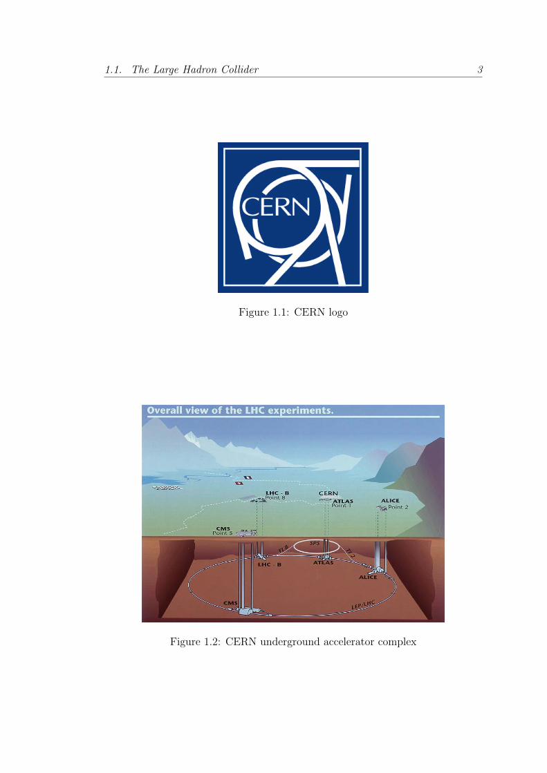
1.1 CERN logo . . . . . . . . . . . . . . . . . . . . . . . . . . . . . . 3
1.2 CERN underground accelerator complex . . . . . . . . . . . . . . 3
1.3 Aerial view of the Large Hadron Collider area with the cycle of the
CERNs accelerators highlighted . . . . . . . . . . . . . . . . . . . 4
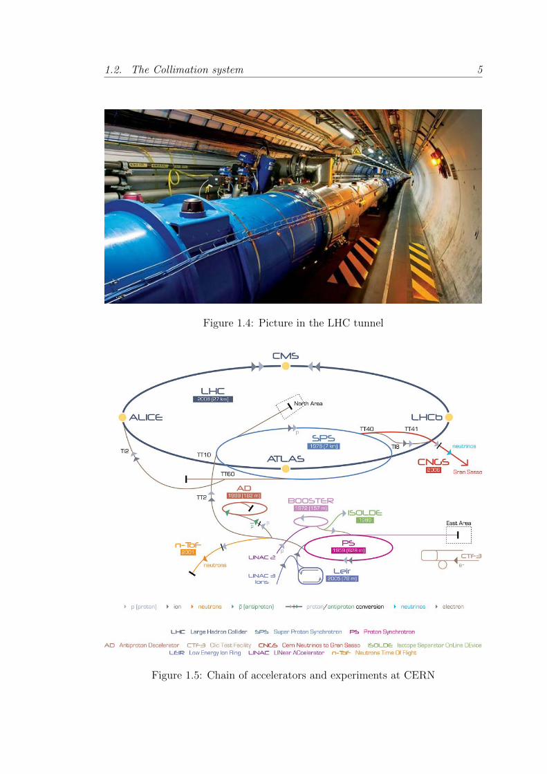
1.4 Picture in the LHC tunnel . . . . . . . . . . . . . . . . . . . . . . 5
1.5 Chain of accelerators and experiments at CERN . . . . . . . . . . 5
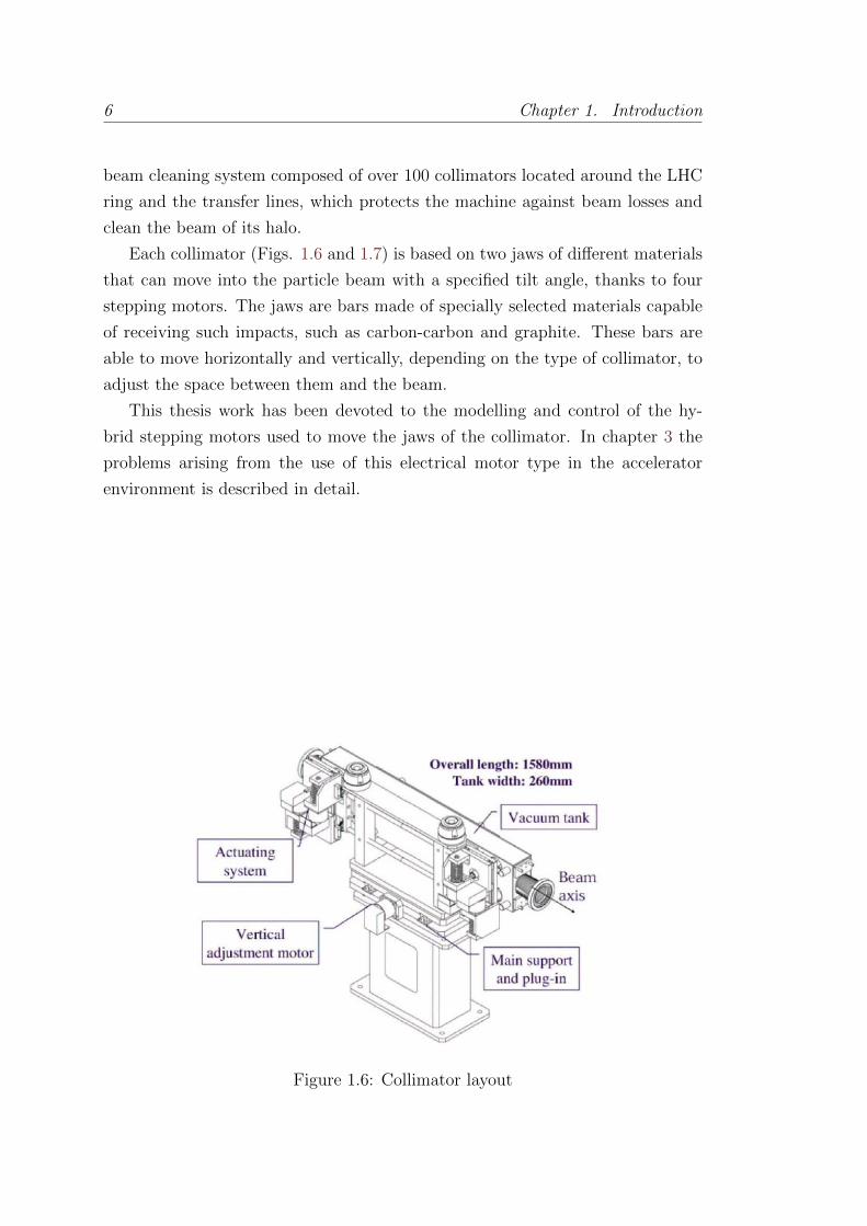
1.6 Collimator layout . . . . . . . . . . . . . . . . . . . . . . . . . . . 6
1.7 Half 3D cut of a collimator . . . . . . . . . . . . . . . . . . . . . 7
1.8 Thesis organization . . . . . . . . . . . . . . . . . . . . . . . . . 8
2.1 Hybrid Stepper Motor separated rotor and stator . . . . . . . . . 10
2.2 Schematic drawing of a simple hybrid stepper motor with 3 teeth
and 2 phases . . . . . . . . . . . . . . . . . . . . . . . . . . . . . 10
2.3 Motor phase equivalent electrical circuit . . . . . . . . . . . . . . 12
2.4 Motor phase high frequency equivalent electrical circuit including
iron losses . . . . . . . . . . . . . . . . . . . . . . . . . . . . . . . 13
2.5 Forces applied to the motor axis . . . . . . . . . . . . . . . . . . 14
2.6 Electromagnetic torque generated for a specific set of reference
currents . . . . . . . . . . . . . . . . . . . . . . . . . . . . . . . . 15
3.1 Rack, collimator and the cable connecting them . . . . . . . . . . 18
3.2 Measured phase currents . . . . . . . . . . . . . . . . . . . . . . . 21
3.3 Measured motor-side currents . . . . . . . . . . . . . . . . . . . . 21
3.4 Measured common-mode phase current. . . . . . . . . . . . . . . 23
3.5 Measured motor-side voltage. . . . . . . . . . . . . . . . . . . . . 23
3.6 Measured rotor angle and speed stepping in half-step mode. . . . 25
4.1 2-port T-net cable model connected to motor phase . . . . . . . . 28
xiii
xiv List of Figures
4.2 Comparison of Gerr(s) transfer function for two different cable
lengths: 100 m and 1 km. . . . . . . . . . . . . . . . . . . . . . . 31
4.3 Motor phase current discrete controller . . . . . . . . . . . . . . . 33
4.4 Standard stepper motor drive scheme . . . . . . . . . . . . . . . . 34
4.5 Connection of the DSP to the MOSFET h-bridges (not all the
components represented) . . . . . . . . . . . . . . . . . . . . . . . 35
4.6 Drive board . . . . . . . . . . . . . . . . . . . . . . . . . . . . . . 36
4.7 State machine diagram . . . . . . . . . . . . . . . . . . . . . . . . 36
4.8 Programmed interrupts . . . . . . . . . . . . . . . . . . . . . . . . 38
4.9 Third harmonic compensation current reference for the extreme
values of α . . . . . . . . . . . . . . . . . . . . . . . . . . . . . . 39
4.10 Typical motor phase current waveforms on the drive and motor
side for a 720 m cable length . . . . . . . . . . . . . . . . . . . . 40
4.11 Repeatability results for the SHS Star 2000, the modified SHS and
the proposed drive . . . . . . . . . . . . . . . . . . . . . . . . . . 41
4.12 Repeatability histograms for 1/4 stepping mode . . . . . . . . . . 43
4.13 Repeatability histograms for 1/8 stepping mode . . . . . . . . . . 43
4.14 Low frequency spectrum of EMI emissions on drive side with a 720
m long cable. . . . . . . . . . . . . . . . . . . . . . . . . . . . . . 44
4.15 The EMI test bench . . . . . . . . . . . . . . . . . . . . . . . . . 44
6.1 Bode magnitude diagram of Gcm(s) for two cable length extremes 55
6.2 Schematic view of drive, motor and cable . . . . . . . . . . . . . . 56
6.3 The approximation Hest(s) and the exact expression Hest(s) for
two cable lengths . . . . . . . . . . . . . . . . . . . . . . . . . . . 61
6.4 Real part of Hest(s)’s poles over a range of cable lengths . . . . . 61
6.5 Low frequency cable model connected to motor phase . . . . . . . 63
6.6 Comparison of the frequency responses of Hv(s) using the complete
impedance expressions and the approximation, for two cable length
extremes . . . . . . . . . . . . . . . . . . . . . . . . . . . . . . . . 63
6.7 Simulation model structure . . . . . . . . . . . . . . . . . . . . . . 65
6.8 True (dashed) and estimated (solid) states for a 1 km cable . . . . 70
6.9 True (dashed) and estimated (solid) states for a 1 km cable with
mismatch; . . . . . . . . . . . . . . . . . . . . . . . . . . . . . . . 71
6.10 RMS of the mechanical angle estimation error . . . . . . . . . . . 72
List of Figures xv
6.11 True (dashed) and estimated (solid) states for a 1 km cable at 150
step/s . . . . . . . . . . . . . . . . . . . . . . . . . . . . . . . . . 73
6.12 LHC Vertical Collimator . . . . . . . . . . . . . . . . . . . . . . . 76
6.13 Experimental test fixture . . . . . . . . . . . . . . . . . . . . . . . 76
6.14 Experimental test setup . . . . . . . . . . . . . . . . . . . . . . . 78
6.15 Position estimation (upper) and estimation error (lower) for a
movement from out to in/beam . . . . . . . . . . . . . . . . . . . 80
6.16 Torque estimation (upper) and estimation error (lower) for a move-
ment from out to in/beam . . . . . . . . . . . . . . . . . . . . . . 80
6.17 Position estimation (upper) and estimation error (lower) for a
trapezoidal movement . . . . . . . . . . . . . . . . . . . . . . . . 82
6.18 Torque estimation (upper) and estimation error (lower) for a trape-
zoidal movement . . . . . . . . . . . . . . . . . . . . . . . . . . . 82
7.1 Discrepancy between measured voltage and standard model pre-
diction. . . . . . . . . . . . . . . . . . . . . . . . . . . . . . . . . . 87
7.2 Measured (dashed) and fitted (solid) open phase voltages. . . . . . 92
7.3 Measured inductance at different positions. . . . . . . . . . . . . . 93
7.4 Estimated and fitted ΨPM1 . . . . . . . . . . . . . . . . . . . . . . . 96
7.5 Holding torque measured for different RMS current values. . . . . 99
7.6 Estimated and fitted L. . . . . . . . . . . . . . . . . . . . . . . . . 101
7.7 Model fit with the position dependent model. . . . . . . . . . . . 102
7.8 Model fit with the current dependent model. . . . . . . . . . . . . 104
7.9 Model fit with the position and current dependent model. . . . . . 106
7.10 Fit percentage of the models for different RMS current datasets . 108
7.11 EKF based closed loop control of the HSM. . . . . . . . . . . . . 111
7.12 Drive signals during closed loop operation. . . . . . . . . . . . . . 112
7.13 Long term position estimation by EKF. . . . . . . . . . . . . . . . 113
7.14 Comparison of EKF using different HSM models. . . . . . . . . . 113
8.1 Full-step mode rotor position and speed acquisition. . . . . . . . 116
8.2 Currents represented in the different frames . . . . . . . . . . . . 121
8.3 Stepper Motor model diagram using the standard ab reference frame121
8.4 dq frame Stepper Motor model diagram . . . . . . . . . . . . . . 123
9.1 Decoupling scheme for idq. . . . . . . . . . . . . . . . . . . . . . . 125
9.2 Current loops in case of ideal decoupling . . . . . . . . . . . . . . 126
xvi List of Figures
9.3 Simplified rotor speed loop . . . . . . . . . . . . . . . . . . . . . 127
9.4 Fit of the system step response to a first order system . . . . . . . 128
9.5 θm loop simplified . . . . . . . . . . . . . . . . . . . . . . . . . . 128
9.6 FOC blocks scheme . . . . . . . . . . . . . . . . . . . . . . . . . 130
9.7 Full-step mode rotor position and speed acquisition, using closed-
loop position control . . . . . . . . . . . . . . . . . . . . . . . . . 131
9.8 Full-step mode step test in standard stepping mode. 10 repetitions
are done . . . . . . . . . . . . . . . . . . . . . . . . . . . . . . . . 132
9.9 Full-step mode step test in FOC mode. 10 repetitions are done . 132
9.10 Stages of θ0 calibration . . . . . . . . . . . . . . . . . . . . . . . 134
9.11 Switch closed to open loop position stages . . . . . . . . . . . . . 135
9.12 Switch closed to open loop position search stage . . . . . . . . . . 137
9.13 Switch closed to open loop position scheme . . . . . . . . . . . . . 138
9.14 Switch from closed to open loop position control in operation . . . 139
9.15 Zoom of the switch from closed to open loop position control in
operation . . . . . . . . . . . . . . . . . . . . . . . . . . . . . . . 139
9.16 Switch from open to closed loop position control in operation . . . 140
9.17 Zoom of the switch from open to closed loop position control in
operation . . . . . . . . . . . . . . . . . . . . . . . . . . . . . . . 140
9.18 Phase currents during a switch transition form closed to open loop,
irefd = 0A. The vertical scale is 1A/division . . . . . . . . . . . . . 141
9.19 Phase currents during a switch transition form closed to open loop,
irefd = 0.5A. The vertical scale is 1A/division . . . . . . . . . . . . 141
9.20 Phase currents during a switch transition form open to closed loop,
irefd = 0.5A. The vertical scale is 1A/division . . . . . . . . . . . . 142
9.21 LHC collimator linear stage . . . . . . . . . . . . . . . . . . . . . 143
9.22 Motor position in the collimator linear stage working in open-loop,
spring relaxed . . . . . . . . . . . . . . . . . . . . . . . . . . . . 144
9.23 Motor position in the collimator linear stage using FOC, spring
relaxed . . . . . . . . . . . . . . . . . . . . . . . . . . . . . . . . 144
9.24 Motor position in the collimator linear stage working in open-loop,
spring at the maximum compression . . . . . . . . . . . . . . . . 145
9.25 Motor position in the collimator linear stage using FOC, spring at
the maximum compression . . . . . . . . . . . . . . . . . . . . . 145
10.1 Typical motor-cable-drive system using an output filter. . . . . . . 150

List of Figures xvii
10.2 Output filter stages. . . . . . . . . . . . . . . . . . . . . . . . . . 151
10.3 Typical two stage induction motor output filter. . . . . . . . . . . 151
11.1 Output filter adapted to a single stepper motor phase . . . . . . . 154
11.2 Simulation results for RDM = Z0 . . . . . . . . . . . . . . . . . . 157
11.3 Zoom for the simulation results for RDM = Z0, motor side . . . . 157
11.4 Simulation results, motor side - Comparison of the proposed filter
and those for R0f = Z0 values . . . . . . . . . . . . . . . . . . . . 158
11.5 Current in a motor phase with the output filter and a 720 meter
cable . . . . . . . . . . . . . . . . . . . . . . . . . . . . . . . . . . 160
11.6 Closer view of the currents a motor phase with the output filter
and a 720 meter cable . . . . . . . . . . . . . . . . . . . . . . . . 160
11.7 Motor side voltage with the output filter and a 720 meter cable. 162
11.8 Motor side voltage with 720 meter cable . . . . . . . . . . . . . . 162
11.9 Repeatability results showing steady state position error histogram
for the SHS Star 2000 drive with a short cable and without the
output filter. . . . . . . . . . . . . . . . . . . . . . . . . . . . . . 163
11.10Repeatability results showing steady state position error histogram
for the SHS Star 2000 drive with a 720 meter cable and with the
proposed output filter. . . . . . . . . . . . . . . . . . . . . . . . . 163
11.11Low frequency spectrum of the EMI emissions for the SHS drive . 164
B.1 CINEL stepper motor based goniometer working principle . . . . 177
B.2 CINEL stepper motor based goniometer prototype . . . . . . . . . 177
B.3 CINEL stepper motor based goniometer 3D model . . . . . . . . . 177
B.4 Crystal platform position with standard stepping mode - one step
applied . . . . . . . . . . . . . . . . . . . . . . . . . . . . . . . . . 179
B.5 Crystal platform position with standard stepping mode - 1 µrad
steps . . . . . . . . . . . . . . . . . . . . . . . . . . . . . . . . . . 179
B.6 Crystal platform position with FOC - 1 µrad steps . . . . . . . . 179
B.7 Crystal platform positioning comparison - continuous motion . . . 180
B.8 CINEL Piezo based goniometer scheme . . . . . . . . . . . . . . . 181
B.9 CINEL Piezo based goniometer. Horizontal version (left) and ver-
tical version (right) . . . . . . . . . . . . . . . . . . . . . . . . . . 181
B.10 CINEL Piezo based goniometer internal picture . . . . . . . . . . 182
B.11 CINEL Piezo based goniometer, rotational stage in open loop . . 183

xviii List of Figures
B.12 CINEL Piezo based goniometer, rotational stage in closed loop . . 183

List of Tables
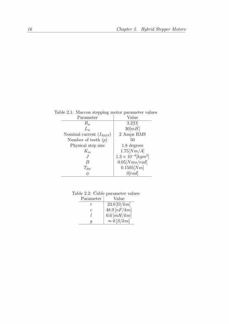
2.1 Maccon stepping motor parameter values . . . . . . . . . . . . . 16
2.2 Cable parameter values . . . . . . . . . . . . . . . . . . . . . . . 16
4.1 Repeatability test comparison without a long cable connecting the
motor . . . . . . . . . . . . . . . . . . . . . . . . . . . . . . . . . 40
4.2 Repeatability test comparison with modified commercial drive and
a long cable connecting drive and motor . . . . . . . . . . . . . . 41
4.3 Repeatability performance in different stepping modes . . . . . . 42
6.1 Parameter values . . . . . . . . . . . . . . . . . . . . . . . . . . . 78
6.2 Results for continuous movement from out-to-in . . . . . . . . . . 79
7.1 Parameters estimated for the standard hybrid stepping motor elec-
tric model . . . . . . . . . . . . . . . . . . . . . . . . . . . . . . . 86
7.2 Magnitude for the first four harmonics of the motor induced volt-
ages when no current is flowing in the phases. . . . . . . . . . . . 91
7.3 ΨPM1 terms resulting from different current levels. . . . . . . . . . 94
7.4 Inductance terms resulting from different current levels. . . . . . . 100
7.5 Parameters estimated for the position dependent model . . . . . . 102
7.6 Parameters estimated for the current dependent model . . . . . . 103
7.7 Parameters estimated for the position and current dependent model106
7.8 Performance of the different models comparing fit and average
computing time . . . . . . . . . . . . . . . . . . . . . . . . . . . . 107
7.9 EKFs Comparison . . . . . . . . . . . . . . . . . . . . . . . . . . 111
11.1 Filter component values. . . . . . . . . . . . . . . . . . . . . . . 156
11.2 Repeatability test results. . . . . . . . . . . . . . . . . . . . . . . 161
xix

xx List of Tables
B.1 Overshoot and standard deviation comparison between stepping
mode and FOC . . . . . . . . . . . . . . . . . . . . . . . . . . . . 178
B.2 Standard deviation of the parasitic yaw in the rotational stage in
closed loop test . . . . . . . . . . . . . . . . . . . . . . . . . . . . 182
List of acronyms
ADC Analog to Digital Converter
AC Alternating Current
CERN European Organization for Nuclear Research
CM Common-Mode
CPU Central Processing Unit
DAQ Data AcQuisition
DC Direct Current
DM Differential-Mode
DSC Digital Signal Controller
DSP Digital Signal Processor
DTC Direct Torque Control
EKF Extended Kalman Filter
EMC Electro-Magnetic Compatibility
EMF Electro-Motive Force
EMI Electro-Magnetic Interference
FOC Field Oriented Control
HSM Hybrid Stepper Motor
IEC International Electrotechnical Commission
IGBT Insulated-Gate Bipolar Transistor
IIR Infinite Impulse Response
LHC Large Hadron Collider
LINAC Linear particle accelerator
LTI Linear Time-Invariant
LVDT Linear Variable Differential Transformer
MDC Motion Drive Control
MOSFET Metal Oxide Semiconductor Field-Effect Transistor
NRMSE Normalized Root Mean Square Error
xxi

xxii List of Tables
PCB Printed Circuit Board
PMSM Permanent-Magnet Stepper Motor
PRS Position Readout and Survey
PWM Pulse Width Modulation
RAM Random Access Memory
RMS Root Mean Square
RMSE Root Mean Square Error
XINT eXternal INTerrupt

Part I
Introduction

Chapter 1
Introduction
This chapter introduces the framework and organization of this thesis. The work
has been carried out at CERN, the European Organization for Nuclear Research,
an organization devoted to the study of particle physics and operating the largest
laboratory in the world with this mission.
CERN is situated on the French-Swiss border (Figs. 1.2 and 1.3), close to
the city of Geneva. It was inaugurated 60 years ago as an effort for international
collaboration after the Second World War and it is composed of over 20 mem-
ber countries of which Spain is part and more than 40 countries in cooperation
agreement, observers or in the process of joining.
1.1 The Large Hadron Collider
The Large Hadron Collider (LHC) (Fig. 1.4) is the latest addition to the CERN’s
accelerator complex (Fig. 1.5). It is a circular particle accelerator and collider,
the largest and most powerful in the world, with a length of 27 km and built 100
meters underground.
The LHC was designed to collide hadron beams, protons and lead ions specif-
ically, with an energy up to 7 TeV each beam, with the purpose of verifying the
Standard Model, the current framework for particle physics.
Inside the collider two proton beams are accelerated in opposite directions at
up to 99.99 % of the speed of light, and they collide in four interaction points,
known as experiments, where the collision data is acquired for later study by the
particle physicists. To make this possible, the superconducting magnets in the
LHC must be cooled down to its working temperature, 1.9 Kelvin (-271 degrees
2
1.1. The Large Hadron Collider 3
Figure 1.1: CERN logo
Figure 1.2: CERN underground accelerator complex

4 Chapter 1. Introduction
Figure 1.3: Aerial view of the Large Hadron Collider area with the cycle of theCERNs accelerators highlighted
Celsius approximately) in order to use the superconducting properties of the
conductors. The LHC has already collided protons with an energy of 8 TeV,
4 per beam, and is currently in the so-called Long Shutdown 1, with works for
upgrading it to work at its maximum energy.
In order for the LHC to work several historical accelerators at CERN are used
in chain. The protons are produced and accelerated in the LINAC-II, a linear
accelerator, and then they are accelerated in steps, first in the Booster, then the
Proton-Synchrotron, the Super Proton-Synchrotron, and finally the LHC.
1.2 The Collimation system
The transverse energy density of the nominal beam in the LHC is 1000 times
higher than that previously achieved in proton storage rings, reaching values up
to 350 MJ for the 2 beams at the time. The energy in the two LHC beams
is sufficient to melt almost 1 ton of copper. Tiny fractions of the stored beam
suffice to quench a super-conducting LHC magnet or even to destroy parts of the
accelerator.
To stop and absorb the energy from the particles that, expectedly or not,
deviate their trajectory over a certain limit from the ideal beam path, there is a
1.2. The Collimation system 5
Figure 1.4: Picture in the LHC tunnel
Figure 1.5: Chain of accelerators and experiments at CERN
6 Chapter 1. Introduction
beam cleaning system composed of over 100 collimators located around the LHC
ring and the transfer lines, which protects the machine against beam losses and
clean the beam of its halo.
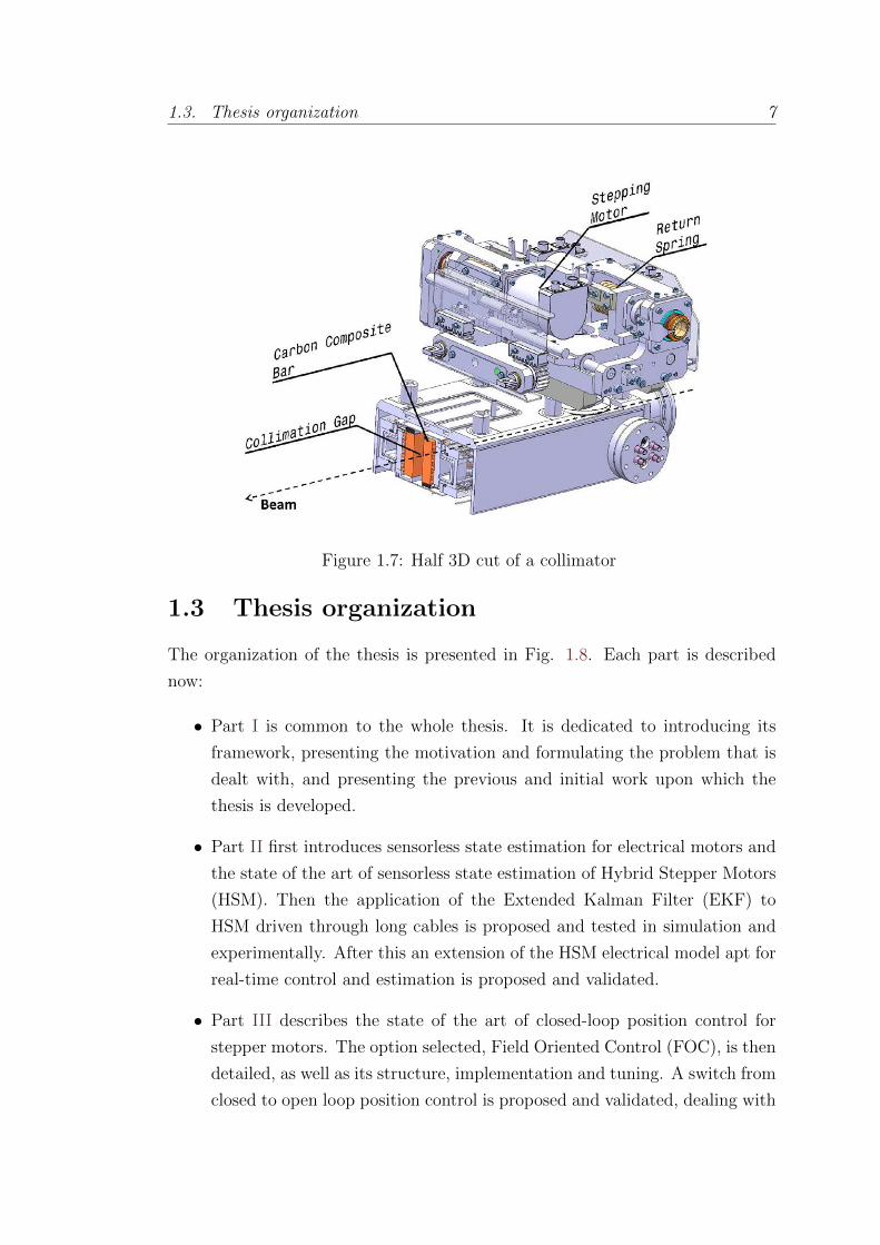
Each collimator (Figs. 1.6 and 1.7) is based on two jaws of different materials
that can move into the particle beam with a specified tilt angle, thanks to four
stepping motors. The jaws are bars made of specially selected materials capable
of receiving such impacts, such as carbon-carbon and graphite. These bars are
able to move horizontally and vertically, depending on the type of collimator, to
adjust the space between them and the beam.
This thesis work has been devoted to the modelling and control of the hy-
brid stepping motors used to move the jaws of the collimator. In chapter 3 the
problems arising from the use of this electrical motor type in the accelerator
environment is described in detail.
Figure 1.6: Collimator layout
1.3. Thesis organization 7
Figure 1.7: Half 3D cut of a collimator
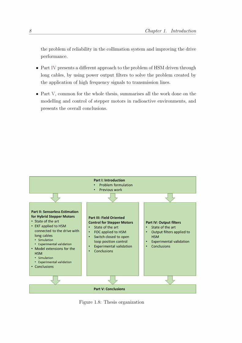
1.3 Thesis organization
The organization of the thesis is presented in Fig. 1.8. Each part is described
now:
• Part I is common to the whole thesis. It is dedicated to introducing its
framework, presenting the motivation and formulating the problem that is
dealt with, and presenting the previous and initial work upon which the
thesis is developed.
• Part II first introduces sensorless state estimation for electrical motors and
the state of the art of sensorless state estimation of Hybrid Stepper Motors
(HSM). Then the application of the Extended Kalman Filter (EKF) to
HSM driven through long cables is proposed and tested in simulation and
experimentally. After this an extension of the HSM electrical model apt for
real-time control and estimation is proposed and validated.
• Part III describes the state of the art of closed-loop position control for
stepper motors. The option selected, Field Oriented Control (FOC), is then
detailed, as well as its structure, implementation and tuning. A switch from
closed to open loop position control is proposed and validated, dealing with
8 Chapter 1. Introduction
the problem of reliability in the collimation system and improving the drive
performance.
• Part IV presents a different approach to the problem of HSM driven through
long cables, by using power output filters to solve the problem created by
the application of high frequency signals to transmission lines.
• Part V, common for the whole thesis, summarises all the work done on the
modelling and control of stepper motors in radioactive environments, and
presents the overall conclusions.
Figure 1.8: Thesis organization
Chapter 2
Hybrid Stepper Motors
2.1 Introduction
In section 1.2 it was mentioned that stepper motors are the actuator chosen to
move the collimator jaws. This choice is based mainly on the fact that this kind
of motor does not need position feedback to work with a relatively high accuracy,
in addition to their great toughness, an essential feature in the given operating
conditions.
Stepping motors are a well known solution for many industrial and consumer
applications, with excellent literature describing them in detail (see [1] and [36]),
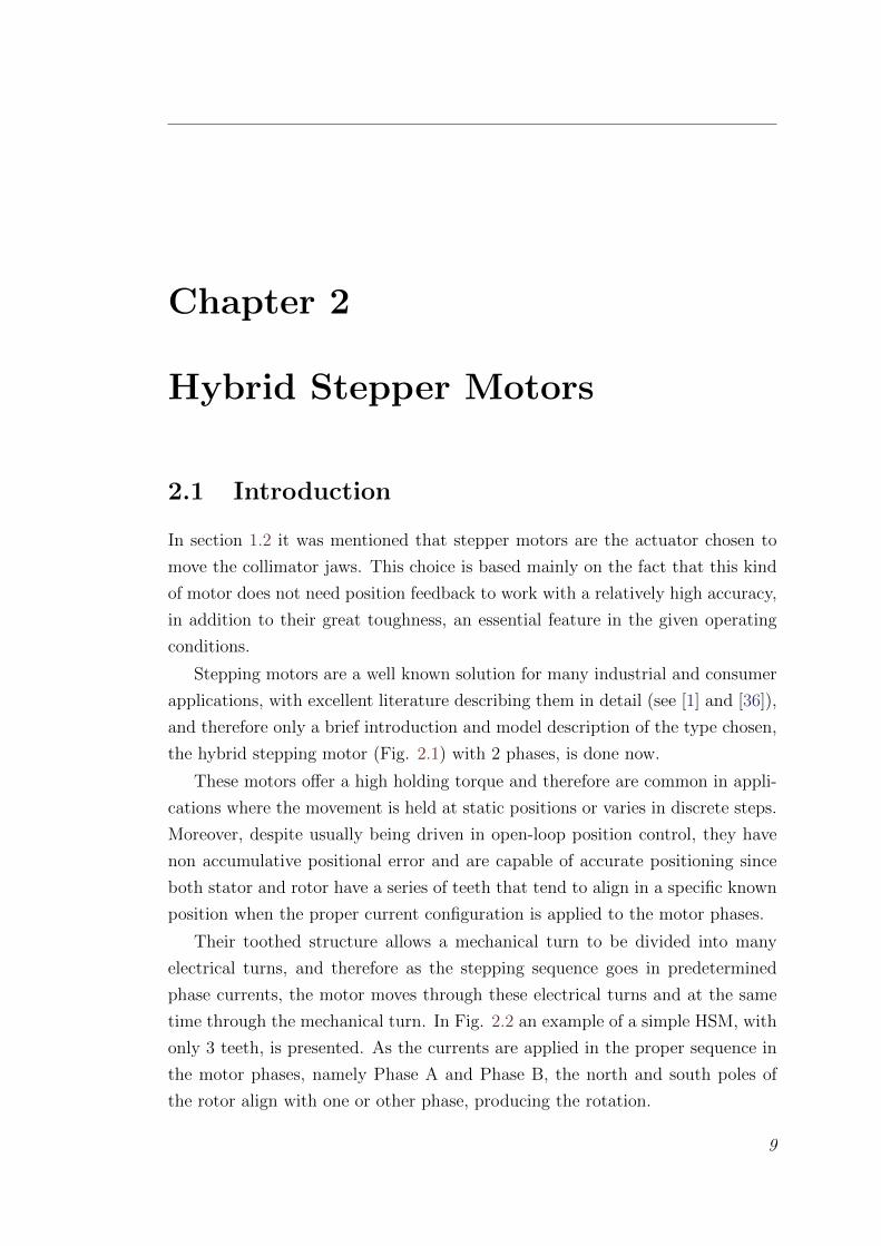
and therefore only a brief introduction and model description of the type chosen,
the hybrid stepping motor (Fig. 2.1) with 2 phases, is done now.
These motors offer a high holding torque and therefore are common in appli-
cations where the movement is held at static positions or varies in discrete steps.
Moreover, despite usually being driven in open-loop position control, they have
non accumulative positional error and are capable of accurate positioning since
both stator and rotor have a series of teeth that tend to align in a specific known
position when the proper current configuration is applied to the motor phases.
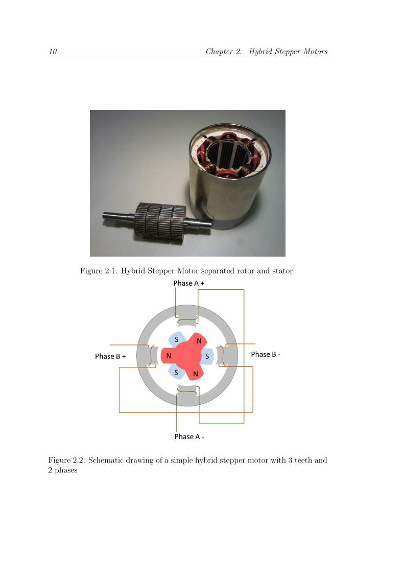
Their toothed structure allows a mechanical turn to be divided into many
electrical turns, and therefore as the stepping sequence goes in predetermined
phase currents, the motor moves through these electrical turns and at the same
time through the mechanical turn. In Fig. 2.2 an example of a simple HSM, with
only 3 teeth, is presented. As the currents are applied in the proper sequence in
the motor phases, namely Phase A and Phase B, the north and south poles of
the rotor align with one or other phase, producing the rotation.
9
10 Chapter 2. Hybrid Stepper Motors
Figure 2.1: Hybrid Stepper Motor separated rotor and stator
Figure 2.2: Schematic drawing of a simple hybrid stepper motor with 3 teeth and2 phases
2.2. Motor model 11
Many of the applications involving long cables to connect the motor either
do not have precise positioning requirements or have the possibility of closing
the loop on the shaft position with sensors such as encoders. Nevertheless when
the motor is situated in harsh environments, it is not possible to use electronic
sensors and achieve a high robustness.
Particles accelerators use positioning systems in multiple different applica-
tions, including collimators, movable targets, beam dumps and scrapers. Hybrid
stepper motors are often used as the actuators in these applications. These mo-
tors, and their electronic drivers, are subject to a number of requirements that
are relatively unique to accelerators. This is the case of the collimators in the
LHC.
2.2 Motor model
The motor model can be separated into two sub-models, an electrical and a
mechanical model. These have different time constants; the electrical model
having faster dynamics.
2.2.1 Electrical model
Each of the two electrical phases of the stepper motor can be modelled at rel-
atively low frequencies and currents as an RL circuit plus a back electromotive
force (emf), as in Fig. 2.3. This circuit is described by the following equation:
Lwdij(t)
dt= −Rwij(t)− ej(t) + uj(t) for j = A,B (2.1)
where Rw is the phase resistance, Lw the phase inductance, ij the phase current,
uj the terminal voltage and the back emf voltages are described by:
eA(t) = −Kmωm sin pθm (2.2)
eB(t) = Kmωm cos pθm,
with Km being the motor constant, p the number of motor pole pairs, ωm the
rotor angular speed and θm the motor mechanical angle. Taking the Laplace

12 Chapter 2. Hybrid Stepper Motors
transform of Eq. (2.1), we find:
Ij(s) =1
Zmot(Uj(s)− Ej(s)) for j = A,B
and
Zmot(s) = Lws+Rw (2.3)
is the motor’s electrical impedance.
High frequency motor phase model
In order to get the transfer functions involving Zmot in the following chapters, an
accurate model of the motor phase impedance is needed. A simple RL model of
the motor phase impedance is not adequate for high PWM frequencies since the
ferromagnetic components of the motor phase circuit have losses that are strong
functions of the frequency.
The high frequency equivalent circuit, like the commonly adopted equivalent
circuit of transformers (see [33]), has an iron-losses resistance, that models the
dissipated active power, in parallel with an equivalent inductance, which has a
value that is considerably lower than the nominal DC value. The presence of an
iron-losses equivalent resistance has the effect of introducing a pole in the high
frequency model of the motor phase impedance:
ZHFmot =
Rw + sLeq1 + sτp
(2.4)
Figure 2.3: Motor phase equivalent electrical circuit
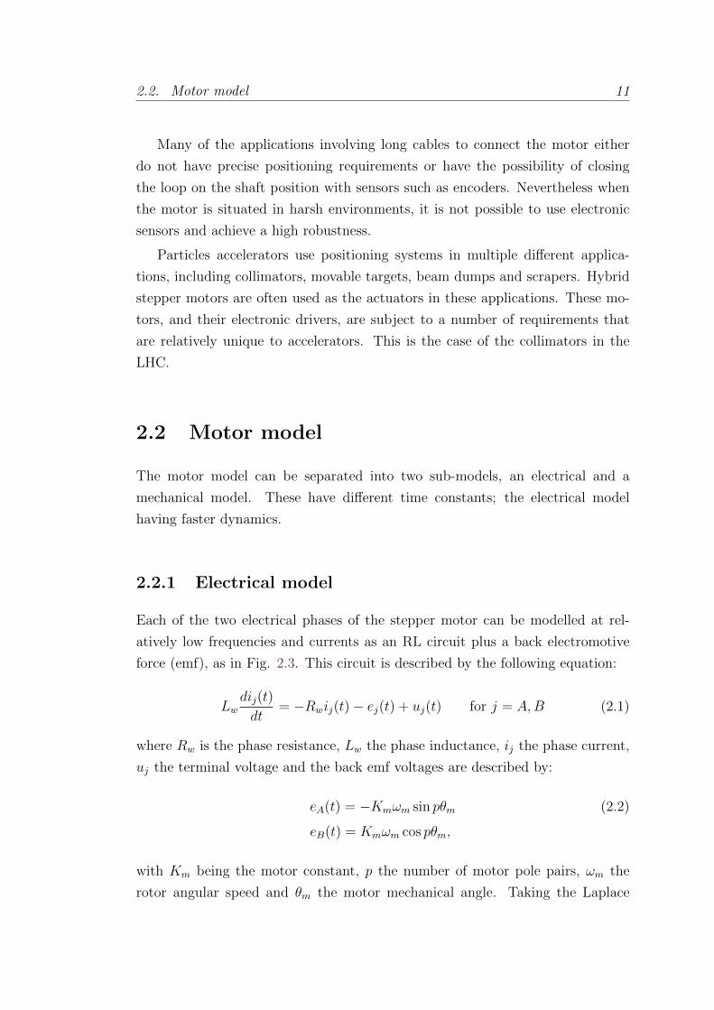
2.2. Motor model 13
where Leq is the equivalent of Lw and Lfe in parallel:
Leq =LfeLwLfe + Lw
and
τp =Rfe
Leq(2.5)
as in [52], where Rfe and Lfe are the resistance and inductance of the core losses
modelling shown in Fig. 2.4.
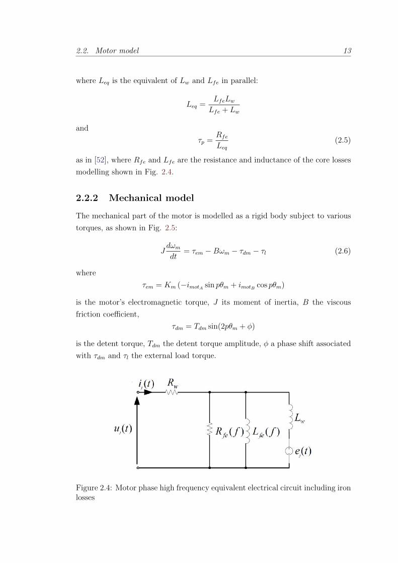
2.2.2 Mechanical model
The mechanical part of the motor is modelled as a rigid body subject to various
torques, as shown in Fig. 2.5:
Jdωmdt
= τem −Bωm − τdm − τl (2.6)
where
τem = Km (−imotA sin pθm + imotB cos pθm)
is the motor’s electromagnetic torque, J its moment of inertia, B the viscous
friction coefficient,
τdm = Tdm sin(2pθm + φ)
is the detent torque, Tdm the detent torque amplitude, φ a phase shift associated
with τdm and τl the external load torque.
Figure 2.4: Motor phase high frequency equivalent electrical circuit including ironlosses
14 Chapter 2. Hybrid Stepper Motors
It should be mentioned that the frequency of the motor’s detent torque is taken
as the electrical frequency’s second harmonic since this was observed experimen-
tally to be dominant for the motors used in the tests in [50]. This dominance
of the second harmonic, over the theoretically predicted fourth, has been found
elsewhere for hybrid stepper motors [88]. No loss of generality occurs, however,
by modelling the detent torque as such and the proposed approach is equally
valid for motors with different dominant detent torque harmonics.
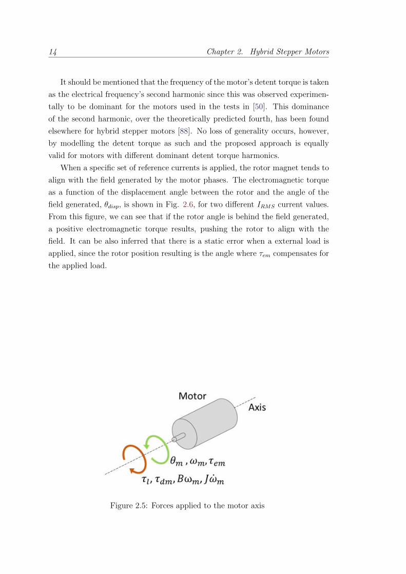
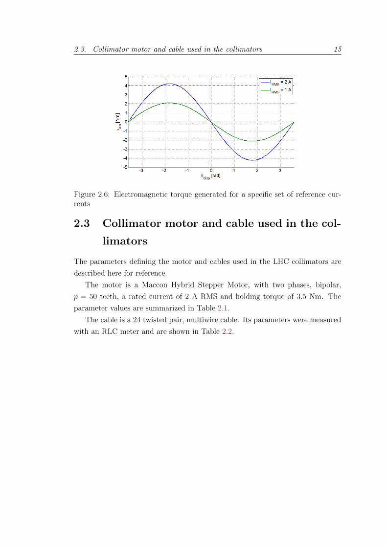
When a specific set of reference currents is applied, the rotor magnet tends to
align with the field generated by the motor phases. The electromagnetic torque
as a function of the displacement angle between the rotor and the angle of the
field generated, θdisp, is shown in Fig. 2.6, for two different IRMS current values.
From this figure, we can see that if the rotor angle is behind the field generated,
a positive electromagnetic torque results, pushing the rotor to align with the
field. It can be also inferred that there is a static error when a external load is
applied, since the rotor position resulting is the angle where τem compensates for
the applied load.
Figure 2.5: Forces applied to the motor axis
2.3. Collimator motor and cable used in the collimators 15
Figure 2.6: Electromagnetic torque generated for a specific set of reference cur-rents
2.3 Collimator motor and cable used in the col-
limators
The parameters defining the motor and cables used in the LHC collimators are
described here for reference.
The motor is a Maccon Hybrid Stepper Motor, with two phases, bipolar,
p = 50 teeth, a rated current of 2 A RMS and holding torque of 3.5 Nm. The
parameter values are summarized in Table 2.1.
The cable is a 24 twisted pair, multiwire cable. Its parameters were measured
with an RLC meter and are shown in Table 2.2.
16 Chapter 2. Hybrid Stepper Motors
Table 2.1: Maccon stepping motor parameter valuesParameter Value
Rw 3.2[Ω]Lw 30[mH]
Nominal current (IRMS) 2 Amps RMSNumber of teeth (p) 50
Physical step size 1.8 degreesKm 1.75[Nm/A]J 1.3× 10⁻⁴[kgm2]B 0.05[Nms/rad]Tdm 0.1505[Nm]φ 0[rad]
Table 2.2: Cable parameter valuesParameter Value
r 23.0 [Ω/km]c 48.9 [nF/km]l 0.6 [mH/km]g ≈ 0 [S/km]

Chapter 3
Problem Formulation
3.1 Introduction
The collimators, presented in section 1.2, are located in highly radioactive areas
due to the task that they perform.
This condition prevents the use of any electronics close to them, such as most
sensors, the microcontrollers and computers running the control algorithms or
the power electronics feeding the actuators that move the collimator jaws. Two
important consequences of this fact are:
• The electronics involved in the control and supplying of these systems are
installed in radiation free areas up to 800 meters away. This means that the
actuators are connected to their drives by cables of this length as illustrated
in Fig. 3.1. Modern drives are usually based on switched inverters. Long
cables behave as transmission lines when switched voltages, containing high
frequency components, are used.
• Position feedback for the motion control loop is limited to radiation hard
sensors. In addition, the harsh conditions withstood by the collimators
make any intervention to repair or replace any sensor or part difficult and
expensive. Therefore, relying only on sensing feedback is preferably avoided.
The need to work without position feedback led to the choice of stepper motors
as actuators in the collimation system. The two characteristics that make them
a great match for the application are their relatively high accuracy in open loop
control, eliminating the need for position feedback and their robustness, avoiding
frequent maintenance.
17

18 Chapter 3. Problem Formulation
Figure 3.1: On the left side an electronic rack and a drive, in a radiation safearea, on the right the collimator with the motors in the accelerator tunnel, inhighly radioactive areas, and on the middle the cable connecting them
In the following sections the consequences of the use of long cables with
switched signals and stepper motors without position feedback is explained in
detail.
3.2 Use of switched drives with long cables
Most stepper motor applications do not require long cables to transfer power to
the motor. However, certain applications, such as in radioactive environments
in particle accelerator complexes (e.g. the LHC at CERN) and nuclear power
plants, or underwater applications, exist where the motor has to be located far
from its power drive. These cases cannot be dealt with directly by most of these
switched motor drives. The long cables, when high frequency PWM signals are
applied, behave like transmission lines, leading to different problems preventing
the motor drives from working appropriately.
Modern electric motor drives work mostly with discrete switches to improve
efficiency compared to linear power supplies, feeding the phases of the motor
with PWM voltage waveforms of high frequencies compared to the mechanical
and electrical bandwidths of the motor, and high voltage amplitudes compared
to the average values applied per chopping period to the motor.
3.2. Use of switched drives with long cables 19
This behaviour is normally acceptable since the phase of the motor is basically
an inductor, and so it acts as a low pass filter for the current when the pulsed
voltage is applied.
However, in the described cases where long cables are used, different effects
arise. This situation has been studied in the general literature of transmission
lines ([59]) and specifically when power motor drives are connected to AC mo-
tors. The effect and sizing of this phenomenon is shown in [37], where the most
relevant cable and motor parameters are studied with specific focus on the over
voltages produced on the motor-side. The critical parameters leading to motor-
side voltages over twice the bridge voltage are also found. In [60] high frequency
models of a cable and motor combination are presented.
In [25] the problem generated in the motor insulation is studied. The short
rise time of technologies like MOSFET and IGBT combined with the high voltage
used, produces such a high du/dt, the derivative of the voltage applied to the
phase with respect to time, that the winding of the motor phase is equivalent to
a network of capacitors, and therefore at switch on time the voltage is held by
the first few turns, leading to turn-to-turn insulation damage.
Nevertheless, very little literature describing the use of stepper motors with
long cables exists, to the author’s knowledge, though the control problem is con-
sidered in [52, 53], where the motor-side current is estimated from the drive-side
current, and the current control loop is closed on this estimation. Details of this
work are given in chapter 4, as it is the starting point of the present thesis.
Now the most important effects on each part of these systems is detailed.
When a pulsed voltage is applied to a long cable, the cable acts as a transmission
line and, depending on the PWM chopping frequency, three important problems
can arise: drive-side current, common-mode current and motor-side voltage.
3.2.1 Drive-side current
The first problem occurs at the drive-side of the cable, where a ringing phenomena
in the current appears. This ringing effect is shown in Fig. 3.2, where a 20 kHz
PWM voltage with 120 V amplitude and fixed duty cycle is applied to a motor
phase through a 720 meter cable. The motor and cable used are the same models
as the ones used in the LHC, described in section 2.3. In this case, the main
ringing effect occurs at the 3rd harmonic of the PWM frequency, 60 kHz. This
effect is due to the relative difference between the characteristic impedance of the

20 Chapter 3. Problem Formulation
cable and the output impedance of the drive, the latter being much smaller than
the former, and causing big current oscillations for negligible oscillations on the
voltage.
The drive-side current can have large amplitude oscillations, over twice its
mean value, and high frequency content, mainly at the harmonics of the PWM
signal, depending on the cable length and characteristics. Some motor drives
do not close the loop on the phase current, and therefore they do not have a
problem with this phenomena though over-current warnings may be triggered.
Many modern drives do, however, use current feedback control in order to achieve
faster dynamics. Normally it then is a problem to deal with this current, specially
with threshold based regulators such as hysteretic regulators, where the ringing
on the current would trigger the controller comparators when the actual current
in the motor is still far from the reference one. Dynamical controllers may work
due to their frequency shaping action that can strongly attenuate the ringing
components, which are high frequency components with respect to the normal
closed loop bandwidths of the motor phase current.
One of the drives used during this work with a hybrid stepper motor is a
commercial switched drive with a nominal RMS current of 2 A. In Fig. 3.3
it can be seen how using this drive the currents in the motor phases are far
from the reference value when a 720 meter cable is used. This occurs because the
comparators in the drive, which compare the current with the reference threshold,
use the oscillating drive-side current, resulting in false detections of the current
overcoming the reference and thus applying an erroneous control action to the
cable.
3.2.2 Common-mode current
For ease of installation reasons, it is common to use multiwire cables when working
with long cables, so that several motors can be driven via a single long cable. This
situation leads to the second problem, the cross-talk between phases and between
phases and shielding. This phenomena provokes an AC CM current in the phase.
This CM current is superimposed on the DM current to form the one shown in
Fig. 3.2.
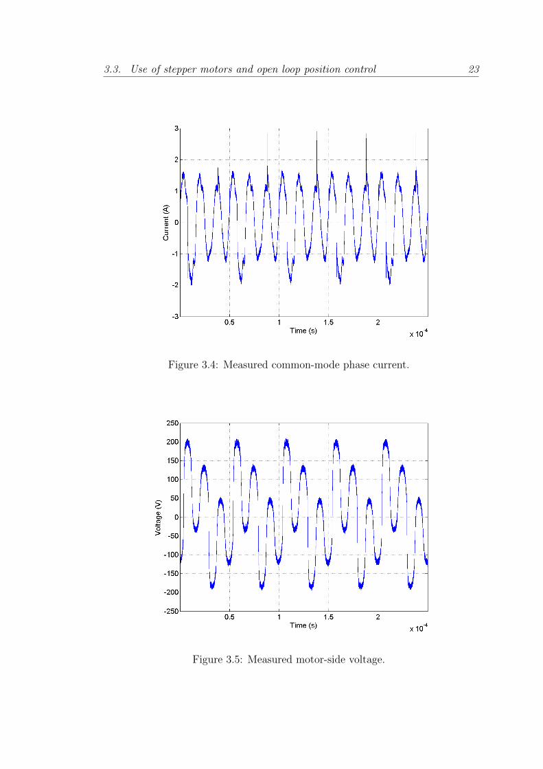
These currents have two main negative effects. Firstly, as mentioned before,
the current controller comparators may be triggered by current spikes, just like
those due to cross talk. In Fig. 3.4 the CM current of a motor phase fed with a

3.2. Use of switched drives with long cables 21
Figure 3.2: Measured phase currents. Blue: drive-side current, green: motor-sidecurrent
Figure 3.3: Measured motor-side currents. Blue: phase A real, green: phase Breal, dashed blue: phase A reference, dashed green: phase B reference

22 Chapter 3. Problem Formulation
fixed duty cycle, 120 V, 20 kHz PWM voltage through a 720 meter, 24 twisted
pair, shielded, multiwire cable is shown. The current peaks in this case exceed
1.5 A, which may suffice to trigger the controller comparators when they should
not.
Secondly, a CM current fed to a long cable produces significant EMI emissions,
creating EMC problems. The consequences of CM currents and EMI emissions
generated in motor applications have been addressed in [81] and [32].
3.2.3 Motor-side voltage
The third problem, at the other extreme of the cable, is the voltage across the
motor terminals. In this case, the impedance of the motor at high frequencies is
much higher than the characteristic impedance of the cable, causing big oscilla-
tions in the voltage for small oscillations on the current.
Depending on the combination of cable length, voltage rise time and PWM
frequency, the oscillations may reach or even exceed twice the applied voltage in
the drive-side of the cable. These oscillation also have relatively high frequency,
that of the PWM frequency and its harmonics.
This effect may lead to insulation breakdown in the motor windings, due to the
high voltage amplitude and derivative. Fig.3.5 shows these motor-side oscillations
when a 120 V, fixed duty cycle, 20 kHz PWM voltage is applied through a 720
meter cable as the one used in the LHC collimators, described in section 2.3.
3.3 Use of stepper motors and open loop posi-
tion control
Hybrid stepper motors are often used as the actuators in positioning systems.
These are robust motors with a relatively high accuracy working in open loop
positioning. For this to be possible, they rely on a precise mechanical construction
and a high nominal electromagnetic torque. The nominal torque of the motor is
chosen at least twice the maximum expected torque in the application. In this
way, if this torque is not overcome, it can be assumed with a good confidence
that the motor is within a known bound of the desired position.
However, in the event of higher than nominal load torques, stepper motors can
lose steps. In order to prevent this, it is of interest to have real-time knowledge
3.3. Use of stepper motors and open loop position control 23
Figure 3.4: Measured common-mode phase current.
Figure 3.5: Measured motor-side voltage.
24 Chapter 3. Problem Formulation
of the motor’s position so that compensatory action can be taken to correct
misalignments or lost steps. Rotary encoders and resolvers can both be used to
provide motor position feedback, but they both increase the positioning system’s
cost and reduce its reliability. In the case at hand, the situation is even worse
since on one side the sensors must be designed to be radiation hard and, on the
other, it is not affordable to reduce the overall reliability of the system. Sensorless
technology is, therefore, an attractive alternative.
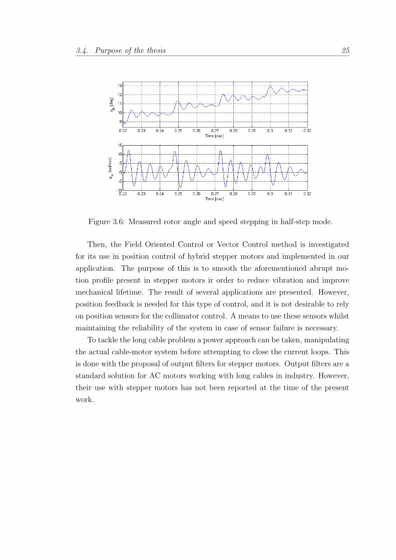
In addition, stepper motors motion profiles are abrupt by nature. As their
name indicates, these profiles are stepped, and therefore high accelerations are
constantly applied. In Fig. 3.6 an example of the rotor’s angle and speed in a
sequence of steps in half-step mode is shown. It can be appreciated how the angle
has big oscillations, leading to high instantaneous speeds. In this example, for an
average speed of roughly 0.65 rads/sec, maximums of 16.4 rads/sec are reached.
This kind of motion profile is hard for the mechanics that are connected to
the motor, and mechanical degradation is unavoidable. For this reason, the use
of sensorless technology is again desirable in order to estimate the mechanical
degradation of the collimators. This is possible thanks to the estimation and
monitoring of the torque applied by the motor during the motion.
During the validation tests of the collimator mechanics, tight margins are set
for the torque applied along the jaw motion range. If this torque changes during
the lifetime of the collimator, sensorless torque estimation would allow it to be
detected before a mechanical failure occurs, allowing for preventive maintenance
during the planned technical stops of the machine, instead of reactive maintenance
forcing a stop of the machine unexpectedly with the costs involved.
3.4 Purpose of the thesis
The purpose of this thesis work is to deal with the problems presented in this
chapter.
The starting point is the work described in chapter 4. An algorithm to esti-
mate the rotor position and the applied load torque with long cables is proposed,
in order to detect steps lost and perform mechanical diagnostics of the collima-
tor. It is developed and implemented in a real-time application. Improvements
in the state-of-the-art for real-time state estimation applied to electrical motors
are necessary for this application.
3.4. Purpose of the thesis 25
Figure 3.6: Measured rotor angle and speed stepping in half-step mode.
Then, the Field Oriented Control or Vector Control method is investigated
for its use in position control of hybrid stepper motors and implemented in our
application. The purpose of this is to smooth the aforementioned abrupt mo-
tion profile present in stepper motors ir order to reduce vibration and improve
mechanical lifetime. The result of several applications are presented. However,
position feedback is needed for this type of control, and it is not desirable to rely
on position sensors for the collimator control. A means to use these sensors whilst
maintaining the reliability of the system in case of sensor failure is necessary.
To tackle the long cable problem a power approach can be taken, manipulating
the actual cable-motor system before attempting to close the current loops. This
is done with the proposal of output filters for stepper motors. Output filters are a
standard solution for AC motors working with long cables in industry. However,
their use with stepper motors has not been reported at the time of the present
work.
Chapter 4
The Stepper Motor Drive
4.1 Introduction
This work started over the base of some previously developed work in the same
project line. In the first part of this chapter, the aforementioned work is described,
in order to give a better understanding of the context. In the second part the
DSP Drive developed and used for the experimental validation during the thesis
is presented.
4.2 Previous work
Analog solution
The first step in the bigger goal of controlling the collimator jaws position with
high precision was to have a stepper drive able to work with long cables, up to 1
km. As presented in section 3.2, commercial PWM drives cannot work properly
with cables of this length due to the high current ringing, and therefore a solution
to overcome this problem was necessary.
This was achieved by a collaboration between CERN engineers and a private
company to produce a modified version of one of their commercial drives, the
SHS Star 2000.
This drive works at 20 kHz PWM chopping frequency and 135 V DC link
voltage. It uses a non-linear control algorithm implemented with a state machine
that applies a fixed frequency PWM with a minimum Ton time, i.e. the time
where the voltage applied to the motor phase is the voltage of the power supply
26
4.2. Previous work 27
used in the H-bridge, and uses a comparator which controls the PWM width,
switching off the voltage applied if the current overcomes the reference and the
minimum Ton has been applied.
It has been designed to work with up to 1 kHz equivalent closed loop band-
width. This value has to be taken carefully since the concept of closed bandwidth
is applicable only to linear systems. However, it gives a good idea of the response
speed in closed loop of the system.
The solution developed is explained in detail in [19]. In consist on the use of a
filtered version of the drive-side current by means of an analog filter implementing
an estimation transfer function which from the drive-side measurement would
provide the motor-side current estimation, and with this estimation the current
loop could be closed.
This solution was implemented and it is the present solution working in the
LHC [53]. However, it has several limitations. The values for the analog filter
estimator where fixed by resistors in a board externally attached to the drive.
This means that only motor side currents for some discrete cable lengths, of a
specific cable type, could be estimated properly.
In addition, one of the main issues of drives when used in large installations
such as the LHC is the emitted electromagnetic field. It can potentially generate
interferences with very sensitive equipment installed either directly in the tun-
nel, since the cables run for hundreds meters all around the tunnel, or in racks
mounted in suitable zones in order to be protected from ionizing radiations.
The most critical emitted frequencies from the power cables lie at the low end
of the spectrum. Increasing the PWM frequency upwards has the double advan-
tage of reducing the current ripple in the motor phase and potentially producing
less powerful emissions in the low frequency range. To accomplish this, there has
to be no subharmonics generated. Nonlinear and hysteresis current controllers
cannot guarantee this constraint whereas fixed PWM period linear controllers do
not have this drawback.
This fact lead to the proposal of a fully digital version of the drive in which
the filter and controller could be calculated from the cable parameters and length,
measurable from the drive with a simple test. The new controller to be imple-
mented in this drive shall be a linear one, since it will avoid the generation of
sub-harmonics of the chopping frequency and it can be made cable length depen-
dant in a relatively simple way.
28 Chapter 4. The Stepper Motor Drive
Digital solution
In [19] the first version of a 5th order digital estimation filter is proposed, based
on the Taylor expansion of the hyperbolic functions that define the transmission
line behaviour (details of this model are given in the following sections). In [52]
an improved version, a 5th order filter based on a balanced Pade approximation
to the hyperbolic functions is used. In [27], a similar approximation is used, but
applied to the final transfer function relating drive-side and motor-side currents,
instead of to the hyperbolic functions independently. In the latter approximation
the order is reduced to 2nd instead of 5th as in the previous ones, after careful
testing of the best estimation performance.
The motor-side current estimation scheme developed in the aforementioned
work is explained next.
4.2.1 Motor-Side Current estimation scheme
Motor and cable model
When the motor phases are connected to a long cable, the behaviour of the
system changes and therefore the model must be updated to include it. The
electrical model includes now a transmission line between drive and motor while
the mechanical model is unaffected by the presence of the cable.
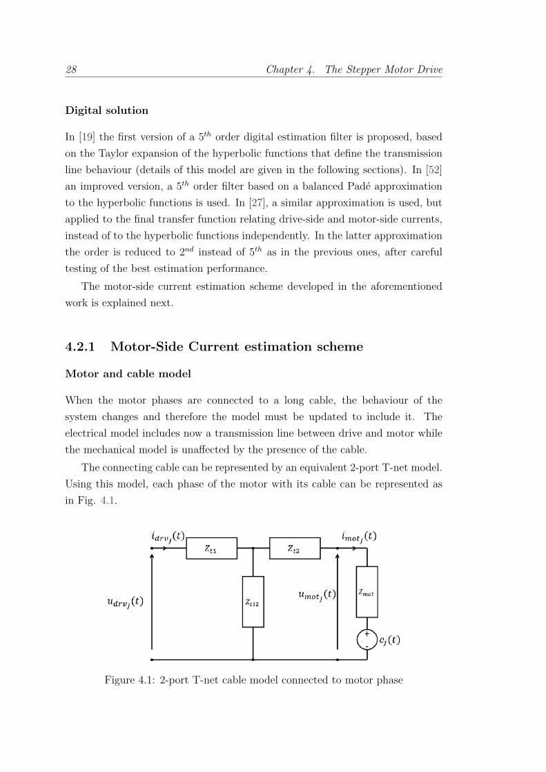
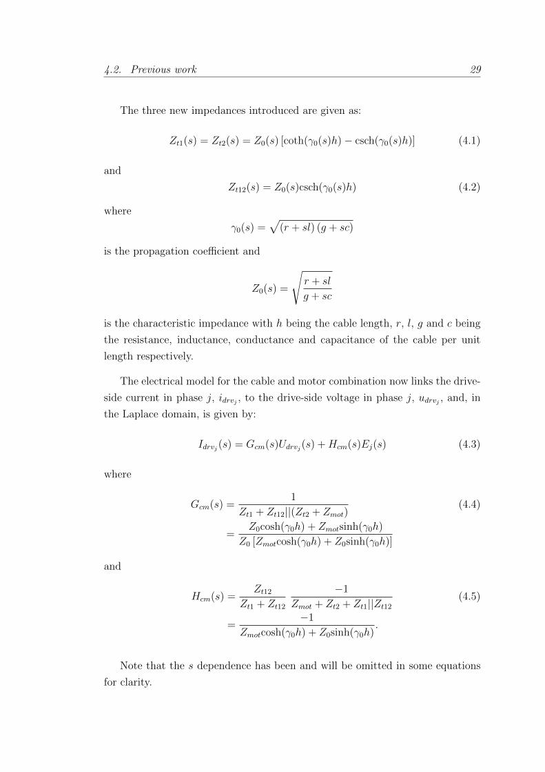
The connecting cable can be represented by an equivalent 2-port T-net model.
Using this model, each phase of the motor with its cable can be represented as
in Fig. 4.1.
Figure 4.1: 2-port T-net cable model connected to motor phase
4.2. Previous work 29
The three new impedances introduced are given as:
Zt1(s) = Zt2(s) = Z0(s) [coth(γ0(s)h)− csch(γ0(s)h)] (4.1)
and
Zt12(s) = Z0(s)csch(γ0(s)h) (4.2)
where
γ0(s) =√
(r + sl) (g + sc)
is the propagation coefficient and
Z0(s) =
√r + sl
g + sc
is the characteristic impedance with h being the cable length, r, l, g and c being
the resistance, inductance, conductance and capacitance of the cable per unit
length respectively.
The electrical model for the cable and motor combination now links the drive-
side current in phase j, idrvj , to the drive-side voltage in phase j, udrvj , and, in
the Laplace domain, is given by:
Idrvj(s) = Gcm(s)Udrvj(s) +Hcm(s)Ej(s) (4.3)
where
Gcm(s) =1
Zt1 + Zt12||(Zt2 + Zmot)(4.4)
=Z0cosh(γ0h) + Zmotsinh(γ0h)
Z0 [Zmotcosh(γ0h) + Z0sinh(γ0h)]
and
Hcm(s) =Zt12
Zt1 + Zt12
−1
Zmot + Zt2 + Zt1||Zt12
(4.5)
=−1
Zmotcosh(γ0h) + Z0sinh(γ0h).
Note that the s dependence has been and will be omitted in some equations
for clarity.
30 Chapter 4. The Stepper Motor Drive
The De-Ringing Filter
In order to virtually eliminate the effects of the transmission line on the control
signal the motor-side current has to be estimated from the only measurable signal
available, the drive side current. To accomplish that it is possible to apply the
current divider rule to the circuit shown in Fig. 4.1. The motor current can be
evaluated by superposition as follows:
Imotj =Zt12
Zt12 + Zt2 + ZmotIdrvj −
1
Zt12 + Zt2 + ZmotEj (4.6)
By means of the transmission lines equations (4.1) and (4.2), it is possible to
write the following expression:
Imotj =Z0
Z0cosh(γ0h) + Zmotsinh(γ0h)Idrvj −
sinh(γ0h)
Z0cosh(γ0h) + Zmotsinh(γ0h)Ej
= GestIdrvj −GerrEj (4.7)
Note that Gerr and Gest are symbols for transfer functions, not conductances
specifically, even though Gerr has the dimensions of one.
Now the estimation error, Iε(s) = Gerr(s)E(s), should be evaluated. For
hybrid stepping motors, the back electromotive forces of the motor phases are
given in (2.2). Even for this type of motors, which have a high value of Km, the
maximum value of the back electromotive force is generally limited to few tens
of volts since they are best suited to low speed applications. Gerr(s) can now be
evaluated and the results shown in Fig. 4.2 for the motor and cable parameter
values reported in tables 2.1 and 2.2, confirming that the estimation error Iε(s)
can be safely neglected for cable lengths of 1 km or even more. Indeed, even
considering the worst case in which Gerr(s) has a maximum, the amplitude of the
back emf at that frequency range is very limited so the attenuation due to Gerr(s)
can be reasonably considered greater than 60 dB. This means that the motor-side
current can be directly estimated from the drive-side current with good precision
by applying Gest(s) to Idrv.
4.2.2 Controller design
A linear controller that, at each PWM fixed period, sets the duty cycle of the
Mosfet bridge has been implemented in order not to jeopardize the shift towards

4.2. Previous work 31
Figure 4.2: Comparison ofGerr(s) transfer function for two different cable lengths:100 m and 1 km.
higher frequencies of the electromagnetic emitted power.
An inverse dynamics controller with an integral action has been designed for
each motor phase current loop. It mainly has a single design parameter: the
closed loop bandwidth Bcl.
Since the phase current is estimated by means of Gest, the system cable - motor
phase can be approximated, for the controller design, by a simple RL circuit with
the following time constant:
τz =Lw + lh
Rw + rh(4.8)
where Rw is the phase winding resistance, rh is the overall cable resistance,
Lw is the DC (or slowly varying) phase inductance and lh is the overall cable
inductance.
It is worth noting that the current references for the usual stepping mode
drive are slow varying compared to the PWM frequency, so it has been decided
to use the nominal DC value for the inductance, whereas this value would not
have been adequate for the drive side current filtering by means of Gest(s).
Taking into account that eventually a pole will be present in the motor phase
impedance Zmot(s) (even if its position is not critical for the controller design)
32 Chapter 4. The Stepper Motor Drive
the closed loop system can be reduced to a single time constant system with:
τcl =1
2πBcl
(4.9)
by means of the following controller:
C(s) = µ1 + sτzs(1 + sτp)
(4.10)
µ = 2πBcl(Rw + rh)
The value of τp, introduced in (2.5), has been fixed at 10µs after different
tests. Even though it is a function of the frequency (see [52]), as already stated,
its precise value is not critical for the controller design as long as it is sufficiently
small compared to τz.
The continuous time controller has then been discretized by means of the
Tustin transformation with a discretization period Tcont equal to the PWM period
allowing the PWM duty cycle to be decided by the controller at each period.
The controller has been parallelized to isolate the integral action in order to
simplify the anti-windup implementation. The controller coefficients have been
analytically expressed in terms of the motor and cable parameters and obviously
in terms of the cable length. Those parameters are set once by the programming
interface (together with many others) whereas the cable length is estimated by a
self-tuning procedure (see [52]).
The scheme of the discrete time controller with causal Anti-Windup is de-
picted in Fig. 4.3. The integral and non-integral actions are clearly distinguished,
the actuator saturation represents the DC voltage supply of the full H Mosfet
bridge whose value is continuously monitored to keep the actuator model up-
dated. The controller coefficients are expressed by the following equations ([50]):
A1 =Tcont − 2τpTcont + 2τp
(4.11)
B0 = B1 = µTcontτz − τp
Tcont + 2τp
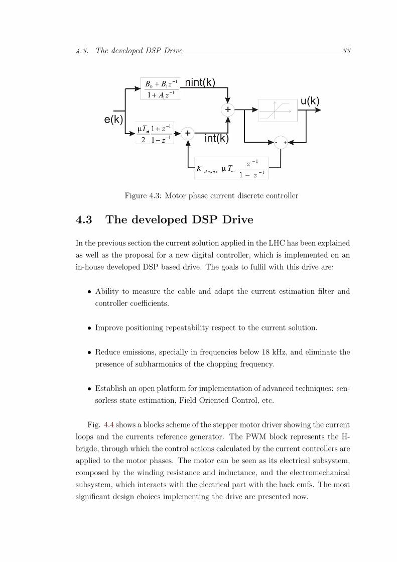
4.3. The developed DSP Drive 33
Figure 4.3: Motor phase current discrete controller
4.3 The developed DSP Drive
In the previous section the current solution applied in the LHC has been explained
as well as the proposal for a new digital controller, which is implemented on an
in-house developed DSP based drive. The goals to fulfil with this drive are:
• Ability to measure the cable and adapt the current estimation filter and
controller coefficients.
• Improve positioning repeatability respect to the current solution.
• Reduce emissions, specially in frequencies below 18 kHz, and eliminate the
presence of subharmonics of the chopping frequency.
• Establish an open platform for implementation of advanced techniques: sen-
sorless state estimation, Field Oriented Control, etc.
Fig. 4.4 shows a blocks scheme of the stepper motor driver showing the current
loops and the currents reference generator. The PWM block represents the H-
brigde, through which the control actions calculated by the current controllers are
applied to the motor phases. The motor can be seen as its electrical subsystem,
composed by the winding resistance and inductance, and the electromechanical
subsystem, which interacts with the electrical part with the back emfs. The most
significant design choices implementing the drive are presented now.

34 Chapter 4. The Stepper Motor Drive
Figure 4.4: Standard stepper motor drive scheme
4.3.1 Hardware design
The power stage of the drive consists of two full Mosfet H-bridges connected to
a DSP as shown in Fig. 4.5. The Mosfets used are IRFB31N20D (ID = 31A,
RDS(on)(max) = 0.082Ω, VDSS = 200V ). The nominal voltage VDD of the drive
is 135 V, but some margin is left for applications with longer cables.
The 8 Mosfets are driven by four IR2183 Mosfet drivers, each one driving a
full leg of the bridge. They are optically coupled to the PWM signals (through a
74HC540D buffer) by means of 8 6N137 optocouplers. Particular attention has
been paid in the electronic design of the board and PCB routing to keep the
power and the signal circuits separated.
At the core of the drive there is the TI TMS320F28335, a full floating point
DSP of the DSC series which fulfils completely the requirements for the appli-
cation having PWMs directly available to drive the bridge and a multiplexed 16
channel 12.5 MS/s, 12 bits ADC to acquire all the relevant signals.
The 150 MHz full floating point CPU simplifies noticeably the code develop-
ment since no conversion to and from fixed point format is needed and consid-
erably enhances the execution speed so the current estimation filters can run at
500 kS/s or even faster. The current measurements are made by means of two
LEM LTSR 6-NP (measuring ranges ± 19.2 A, ±12.8 A, ±6.4 A, DC-200 kHz
bandwidth -1 dB). A high measurement range is required in order to correctly
reproduce the ringing at the filter inputs.
An anti-aliasing stage has been foreseen with a -3 dB bandwidth of 30 kHz
which is the -3 dB maximum bandwidth of Gest (this corresponds to the esti-
mated bandwidth of a 100 m cable, the cable and motor parameters are reported

4.3. The developed DSP Drive 35
Figure 4.5: Connection of the DSP to the MOSFET h-bridges (not all the com-ponents represented)
in section 2.3. The anti-aliasing filter design is not critical since the nominal
sampling rate is greater than 500 kS/s so at least one decade on the right of the
maximum -3 dB bandwidth.
The board details are illustrated in Fig. 4.6, where the most important com-
ponents have been highlighted. On the leftmost of the picture there are the two
current sensors. Next to them, there are the Mosfet bridges covered by the heat
sink. Next, on the right, the Mosfet drivers are visible and further on the right
the optocouplers that electrically insulate the signal part of the board from the
power part. On the right of the optocouplers there is eventually the DSP and the
circuitry devoted to the communication.
4.3.2 Software design
The drive, whose state diagram is shown in Fig. 4.7, has been designed to be
interfaced to any stepper module. The program is stored in the flash memory of
the DSP and it is transferred to the RAM memory at power up. Once the initial-
ization procedure is performed, the cable length measurement and the consequent
tuning is performed during this phase, the DSP goes into an infinite empty loop
waiting for the different interrupts (see Fig. 4.8).
These interrupts have a specific priority selected to satisfy the real time con-
straints. The fastest one, executing the current estimation filter, is executed with

36 Chapter 4. The Stepper Motor Drive
Figure 4.6: Drive board
Figure 4.7: State machine diagram
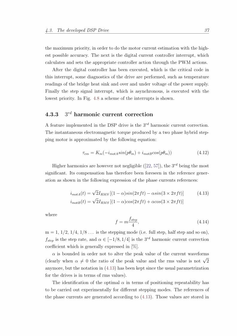
4.3. The developed DSP Drive 37
the maximum priority, in order to do the motor current estimation with the high-
est possible accuracy. The next is the digital current controller interrupt, which
calculates and sets the appropriate controller action through the PWM actions.
After the digital controller has been executed, which is the critical code in
this interrupt, some diagnostics of the drive are performed, such as temperature
readings of the bridge heat sink and over and under voltage of the power supply.
Finally the step signal interrupt, which is asynchronous, is executed with the
lowest priority. In Fig. 4.8 a scheme of the interrupts is shown.
4.3.3 3rd harmonic current correction
A feature implemented in the DSP drive is the 3rd harmonic current correction.
The instantaneous electromagnetic torque produced by a two phase hybrid step-
ping motor is approximated by the following equation:
τem = Km(−imotAsin(pθm) + imotBcos(pθm)) (4.12)
Higher harmonics are however not negligible ([22, 57]), the 3rd being the most
significant. Its compensation has therefore been foreseen in the reference gener-
ation as shown in the following expression of the phase currents references:
imotA(t) =√
2IRMS [(1− α)sin(2πft)− αsin(3× 2πft)] (4.13)
imotB(t) =√
2IRMS [(1− α)cos(2πft) + αcos(3× 2πft)]
where
f = mfstep
4, (4.14)
m = 1, 1/2, 1/4, 1/8 . . . is the stepping mode (i.e. full step, half step and so on),
fstep is the step rate, and α ∈ [−1/8, 1/4] is the 3rd harmonic current correction
coefficient which is generally expressed in [%].
α is bounded in order not to alter the peak value of the current waveforms
(clearly when α 6= 0 the ratio of the peak value and the rms value is not√
2
anymore, but the notation in (4.13) has been kept since the usual parametrization
for the drives is in terms of rms values).
The identification of the optimal α in terms of positioning repeatability has
to be carried out experimentally for different stepping modes. The references of
the phase currents are generated according to (4.13). Those values are stored in
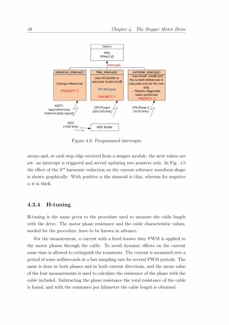
38 Chapter 4. The Stepper Motor Drive
Figure 4.8: Programmed interrupts
arrays and, at each step edge received from a stepper module, the next values are
set: an interrupt is triggered and served updating two pointers only. In Fig. 4.9
the effect of the 3rd harmonic reduction on the current reference waveform shape
is shown graphically. With positive α the sinusoid is thin, whereas for negative
α it is thick.
4.3.4 H-tuning
H-tuning is the name given to the procedure used to measure the cable length
with the drive. The motor phase resistance and the cable characteristic values,
needed for the procedure, have to be known in advance.
For the measurement, a current with a fixed known duty PWM is applied to
the motor phases through the cable. To avoid dynamic effects on the current
some time is allowed to extinguish the transients. The current is measured over a
period of some milliseconds at a fast sampling rate for several PWM periods. The
same is done in both phases and in both current directions, and the mean value
of the four measurements is used to calculate the resistance of the phase with the
cable included. Subtracting the phase resistance the total resistance of the cable
is found, and with the resistance per kilometre the cable length is obtained.
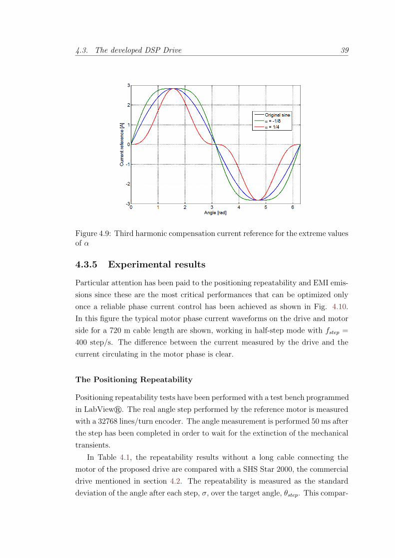
4.3. The developed DSP Drive 39
Figure 4.9: Third harmonic compensation current reference for the extreme valuesof α
4.3.5 Experimental results
Particular attention has been paid to the positioning repeatability and EMI emis-
sions since these are the most critical performances that can be optimized only
once a reliable phase current control has been achieved as shown in Fig. 4.10.
In this figure the typical motor phase current waveforms on the drive and motor
side for a 720 m cable length are shown, working in half-step mode with fstep =
400 step/s. The difference between the current measured by the drive and the
current circulating in the motor phase is clear.
The Positioning Repeatability
Positioning repeatability tests have been performed with a test bench programmed
in LabViewr. The real angle step performed by the reference motor is measured
with a 32768 lines/turn encoder. The angle measurement is performed 50 ms after
the step has been completed in order to wait for the extinction of the mechanical
transients.
In Table 4.1, the repeatability results without a long cable connecting the
motor of the proposed drive are compared with a SHS Star 2000, the commercial
drive mentioned in section 4.2. The repeatability is measured as the standard
deviation of the angle after each step, σ, over the target angle, θstep. This compar-
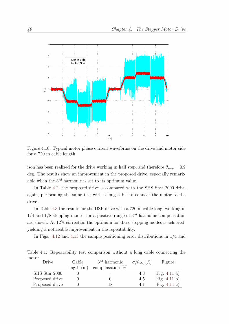
40 Chapter 4. The Stepper Motor Drive
Figure 4.10: Typical motor phase current waveforms on the drive and motor sidefor a 720 m cable length
ison has been realized for the drive working in half step, and therefore θstep = 0.9
deg. The results show an improvement in the proposed drive, especially remark-
able when the 3rd harmonic is set to its optimum value.
In Table 4.2, the proposed drive is compared with the SHS Star 2000 drive
again, performing the same test with a long cable to connect the motor to the
drive.
In Table 4.3 the results for the DSP drive with a 720 m cable long, working in
1/4 and 1/8 stepping modes, for a positive range of 3rd harmonic compensation
are shown. At 12% correction the optimum for these stepping modes is achieved,
yielding a noticeable improvement in the repeatability.
In Figs. 4.12 and 4.13 the sample positioning error distributions in 1/4 and
Table 4.1: Repeatability test comparison without a long cable connecting themotor
Drive Cable 3rd harmonic σ/θstep[%] Figurelength (m) compensation [%]
SHS Star 2000 0 - 4.8 Fig. 4.11 a)Proposed drive 0 0 4.5 Fig. 4.11 b)Proposed drive 0 18 4.1 Fig. 4.11 c)
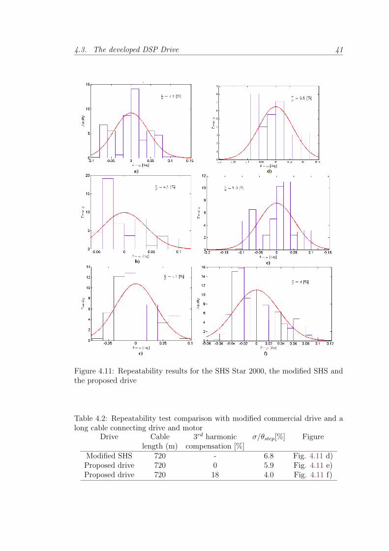
4.3. The developed DSP Drive 41
Figure 4.11: Repeatability results for the SHS Star 2000, the modified SHS andthe proposed drive
Table 4.2: Repeatability test comparison with modified commercial drive and along cable connecting drive and motor
Drive Cable 3rd harmonic σ/θstep[%] Figurelength (m) compensation [%]
Modified SHS 720 - 6.8 Fig. 4.11 d)Proposed drive 720 0 5.9 Fig. 4.11 e)Proposed drive 720 18 4.0 Fig. 4.11 f)
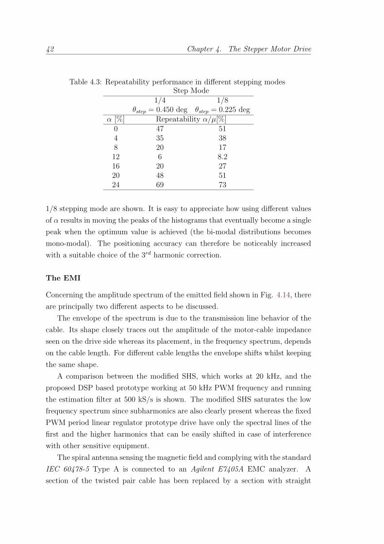
42 Chapter 4. The Stepper Motor Drive
Table 4.3: Repeatability performance in different stepping modesStep Mode
1/4 1/8θstep = 0.450 deg θstep = 0.225 deg
α [%] Repeatability α/µ[%]0 47 514 35 388 20 1712 6 8.216 20 2720 48 5124 69 73
1/8 stepping mode are shown. It is easy to appreciate how using different values
of α results in moving the peaks of the histograms that eventually become a single
peak when the optimum value is achieved (the bi-modal distributions becomes
mono-modal). The positioning accuracy can therefore be noticeably increased
with a suitable choice of the 3rd harmonic correction.
The EMI
Concerning the amplitude spectrum of the emitted field shown in Fig. 4.14, there
are principally two different aspects to be discussed.
The envelope of the spectrum is due to the transmission line behavior of the
cable. Its shape closely traces out the amplitude of the motor-cable impedance
seen on the drive side whereas its placement, in the frequency spectrum, depends
on the cable length. For different cable lengths the envelope shifts whilst keeping
the same shape.
A comparison between the modified SHS, which works at 20 kHz, and the
proposed DSP based prototype working at 50 kHz PWM frequency and running
the estimation filter at 500 kS/s is shown. The modified SHS saturates the low
frequency spectrum since subharmonics are also clearly present whereas the fixed
PWM period linear regulator prototype drive have only the spectral lines of the
first and the higher harmonics that can be easily shifted in case of interference
with other sensitive equipment.
The spiral antenna sensing the magnetic field and complying with the standard
IEC 60478-5 Type A is connected to an Agilent E7405A EMC analyzer. A
section of the twisted pair cable has been replaced by a section with straight
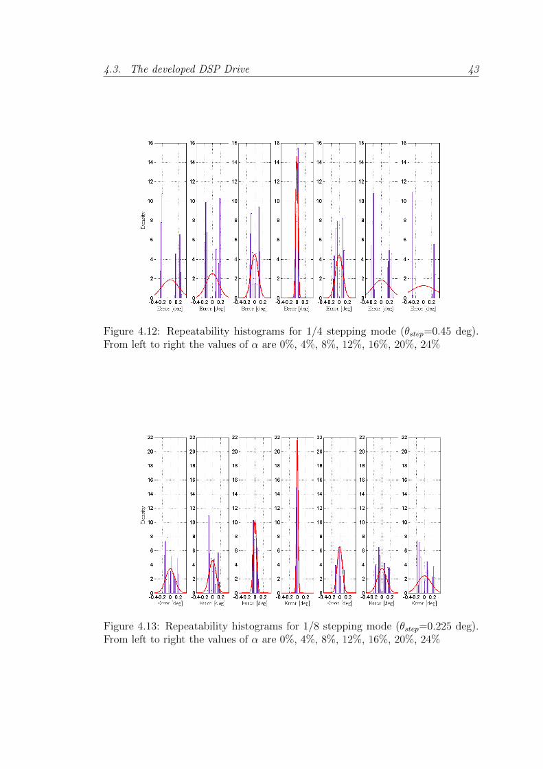
4.3. The developed DSP Drive 43
Figure 4.12: Repeatability histograms for 1/4 stepping mode (θstep=0.45 deg).From left to right the values of α are 0%, 4%, 8%, 12%, 16%, 20%, 24%
Figure 4.13: Repeatability histograms for 1/8 stepping mode (θstep=0.225 deg).From left to right the values of α are 0%, 4%, 8%, 12%, 16%, 20%, 24%
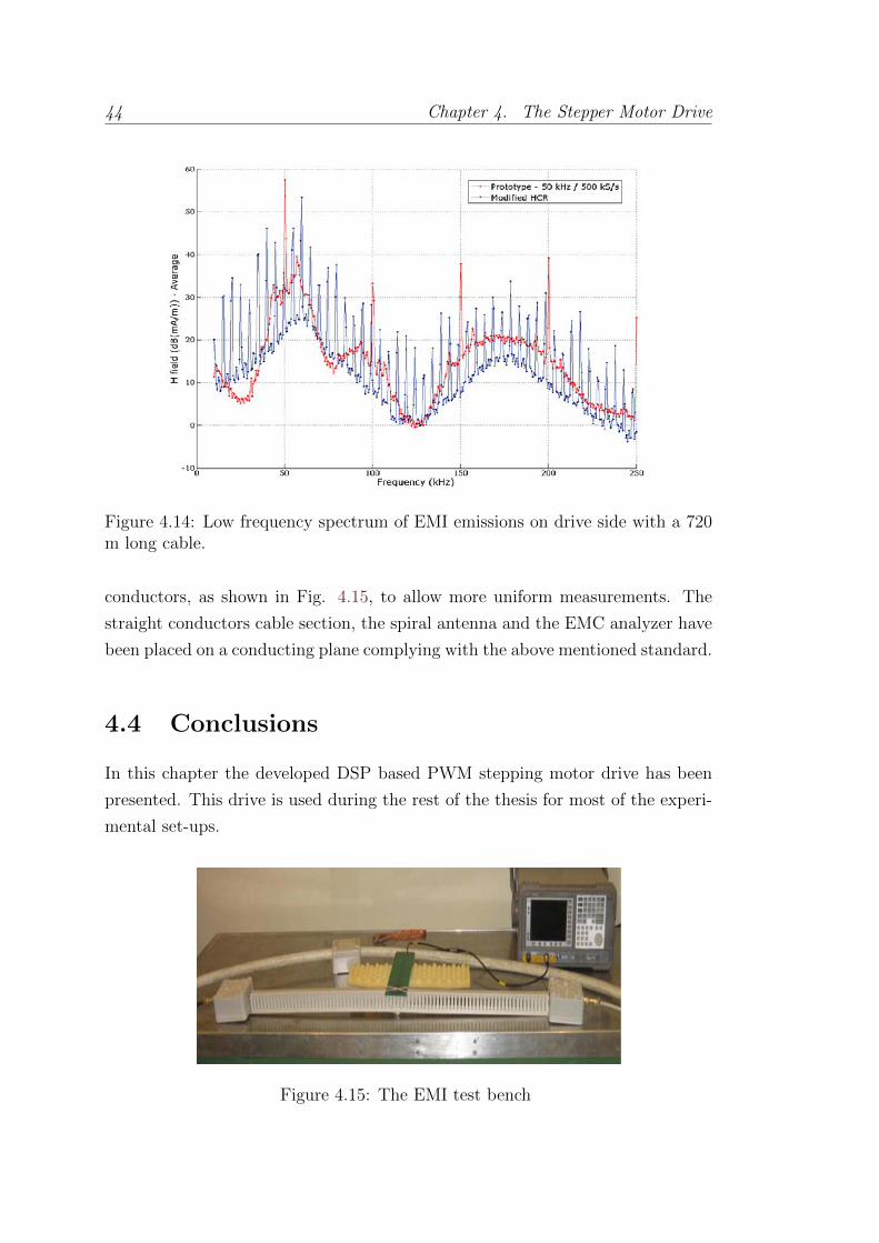
44 Chapter 4. The Stepper Motor Drive
Figure 4.14: Low frequency spectrum of EMI emissions on drive side with a 720m long cable.
conductors, as shown in Fig. 4.15, to allow more uniform measurements. The
straight conductors cable section, the spiral antenna and the EMC analyzer have
been placed on a conducting plane complying with the above mentioned standard.
4.4 Conclusions
In this chapter the developed DSP based PWM stepping motor drive has been
presented. This drive is used during the rest of the thesis for most of the experi-
mental set-ups.
Figure 4.15: The EMI test bench

4.4. Conclusions 45
The prototype is operated at 50 kHz chopping frequency though this frequency
is configurable, and it is designed to work with cables up to 1 km length. Mea-
surement results show that the positioning repeatability is improved with respect
to the modified commercial drive and can reach similar values with and without
long cables when applying the appropriate 3rd harmonic correction on the phase
current reference generation. The EMI emitted from the power cable has been
drastically reduced with a linear controller and the achieved chopping frequency,
which shifted the emitted energy spectrum to high frequencies.
Part II
Sensorless Estimation for Hybrid
Stepper Motors

Chapter 5
Introduction to Position and
Torque Sensorless Estimation
5.1 Motivation
Good motor positioning repeatability and the capability to detect lost steps is of
great importance for a proper operation of the collimators. It is thus necessary
to have real-time knowledge of the motor position in order that compensatory
action can be taken to correct any misalignments.
However, working in a high radiation environment makes things more difficult
than usual, as seen in chapter 3. Most position and torque sensors do not function
correctly in these working conditions, and even though there are sensors like the
Linear Variable Differential Transformer (LVDT) or the Resolver that can be
constructed to be radiation-hard, the system cannot rely solely on them since
failure is not affordable: intervention in the collimation areas is extremely difficult
and expensive due to the radiation, even during the machine technical stops.
In addition, even if the stepping motors work at nominal torque, chosen by
design to be at least twice the nominal load torque, having an estimate of the
real load torque can be useful to warn of mechanical degradation. All the LHC
collimators have passed acceptance tests where the load torques over the entire
axes strokes have been measured and verified. Load torque warning thresholds
can be easily determined for each collimator axis according to the collimator type
and orientation.
For the aforementioned reason, high robustness is mandatory. Failure of the
sensors must not be critical, and therefore redundancy through sensorless methods
47
48 Chapter 5. Introduction to Position and Torque Sensorless Estimation
is desirable.
With the increase in power and decrease in cost of embedded processors in
recent years, the drives used to power and control stepper motors have become in-
creasingly sophisticated. For example, in [88] compensation of the detent torque
and several harmonics of the HSM in the quadrature axis component of the cur-
rent is proposed, both for use in open loop, where the angle used for the Park
Transform is the command position, and closed loop, where an encoder is used
for position information, in order to prevent the motor characteristic resonances.
Improved diagnostics can thus be achieved through the use of sensorless algo-
rithms instead of via additional sensors, with their associated higher costs and
lower reliability.
In this part, firstly the application of a well known sensorless technique, the
Kalman Filter, and specifically its variation adapted to deal with non-linear sys-
tems, the Extended Kalman Filter, is proposed to get the desired estimate of
motor position and torque despite the presence of long cables. Then novel HSM
model extensions are proposed and used in the EKF to further improve the esti-
mation performance.
The Kalman Filter is well documented, with classic books like [14] and more
modern ones like [30, 79], to cite only a few. [58] is also a classic from literature
where the Kalman Filter is explained in a very intuitive way thanks to a simple
example where the author proposes to take the place of someone trying to estimate
his own position. [31] gives as well a very friendly approach to the filter first with
a single state example and then extending it to any number of states, by using the
associated information matrix of a Gaussian distribution to explain the process
for getting the filter equations.
The Kalman Filter is widely used in different industrial applications. In [3] a
review of the main fields where it is used is given, sensorless control and diagnos-
tics of motor drives being the main topics.
5.2. State of the art 49
5.2 State of the art
5.2.1 On the use of the Extended Kalman Filter with Hy-
brid Stepper Motors connected Through Long Ca-
bles
Sensorless position and torque estimation techniques have been applied to Hy-
brid and Permanent Magnet Stepping Motors previously, largely due to the vast
increase in computational power in modern embedded devices, such as Digital
Signal Processors (DSP), at ever decreasing costs. [2] does a review of position es-
timation techniques for brushless permanent-magnet machines, by measurement
of the back electro-motive force, the inductance variation and the flux-linkage
variation, using direct estimation methods or observers. A similar review is per-
formed in [38], focusing on brushless DC motors, but in addition the current
injection method is considered and the estimation is presented for generators as
well. [13] presents a review of high frequency injection methods for rotor position
estimation.
A number of torque and position estimation techniques for stepping motors
have been proposed using different methods. In [39] a disturbance observer is
proposed for use with permanent-magnet stepper motors. Focused on hybrid
stepper motors are some examples like [92], where a torque estimation technique
without the feedback of speed or position sensors is proposed, and [94], where a
damping control system using a speed and position observed based on a phase-
locked loop that tracks the phase angle of the back electro-motive force voltage
is presented. However, unlike the Extended Kalman Filter, they do not provide
a unified method for full state estimation, rather only concentrating on a single
signal.
Despite its relatively high computational complexity, the Kalman Filter, and
more specifically the Extended Kalman Filter (EKF), has become one of the
favoured approaches for sensorless position estimation in electric motors. For
example in [12] the EKF is used to estimate position and angular speed in a
permanent magnet synchronous motor drive and these estimations are used to
close the angular control loop. In [87] the EKF is applied to estimate the same
states for a brushless DC motor, with the addition that the filter is implemented
both with fixed motor parameters and with online estimation of the stator resis-
50 Chapter 5. Introduction to Position and Torque Sensorless Estimation
tance, allowing for an improvement of the estimation specially at low speeds. An
example of an application to induction motors can be found in [5].
The Kalman Filter estimates the motor states in an statistically optimal way
despite the presence of both measurement and process disturbances. Further-
more, unknown inputs to the motor, such as an external load torque, can also be
estimated in a structured way. This method has been used in different aspects of
industry, e.g. in [77] the EKF estimates the unknown disturbance forces used for
real-time active magnetic bearing control; in [45] the EKF is used to estimate un-
known parameters and driving torque in an industrial manipulator with flexible
joints.
State estimation for hybrid stepper motors, including the torque load, has
been considered before in the literature, examples of this can be found in [62,
66, 67], where the filter is used for sensorless control of the motor, and in [6, 7]
where in addition an effort to reduce the computational cost of the filter is done
by proposing an steady-state Kalman filter. However, up to the date when this
work was developed, the case of connecting the motor with long cables had not
yet been dealt with for sensorless estimation.
As is discussed in chapter 6, direct application of the EKF to a model of cable
plus motor is not feasible for real-time applications due to restricted processing
power, and a way to overcome this is proposed and demonstrated.
In addition, the proposed philosophy to applying an EKF to a drive connected
to a stepper motor by long cables is completely general and could be applied to
other types of motors connected in this way, as are commonly found in particle
accelerators, nuclear power plants, oil extraction [20] or underwater applications.
In the food industry motors are placed in clean areas far from the drives. Even
in some cases aerial vehicles use a long cable connecting the motor [8].
5.2.2 On the Hybrid Stepper Motor Electrical Model
The utilization of the EKF with HSM connected through long cables can be
achieved successfully. Sensorless estimation allows the angular position of the
motor to be estimated in real-time by optimally combining measurements of the
motor electrical signals, current and voltage, with the prediction of a model of
the motor. However, a consistent mismatch between the predicted voltage in
the motor phase using the standard model for the HSM found in literature (see
chapter 2) and the experimental results was noticed. In Fig. 7.1 this effect is

5.3. The Extended Kalman Filter 51
shown: there is a discrepancy when the phase has a non-zero current.
HSM modelling has received attention in the literature and typically the mod-
els fall into two categories, either for motor design or for control. Despite attempts
to develop simpler models and analysis techniques e.g. [40, 41], models for motor
design are normally of such high complexity that their use in real-time algorithms
running on embedded processors is not possible. Models for control are at the
other end of the complexity spectrum, being generic models that apply not only
to HSMs , but also to Permanent Magnet Stepping Motors (PMSMs) and even
more generally to permanent magnet AC synchronous motors. Practically all the
references given for the use of EKF on HSM fall into this category.
This observation leads to the goal of improving the motor model whilst keep-
ing it usable for real-time applications in embedded systems. Two extensions to
the standard model of the electrical subsystem of an HSM, dependant on the rotor
position and phase current respectively, are proposed in chapter 7. A combined
model, which is simultaneously dependent on position and current is developed
as well and magnetic theory is used to give an expression of the predicted elec-
tromagnetic torque. To demonstrate its success at reaching the goal, it is used in
a real-time application.
5.3 The Extended Kalman Filter
In the previous section several references to the theory of the Kalman Filter and
its extended version were given. A summary of its equations, which are used in
this work, is given below.
For a discrete-time, nonlinear time-invariant system represented by the fol-
lowing state-space equations:
xk+1 =f(xk,uk) + wk (5.1)
yk+1 =h(xk+1) + vk+1,
where xk ∈ Rn is the state vector at time step k, f the real valued, differentiable
state transition function, uk ∈ Rr the system input, wk ∈ Rn the process noise,
yk ∈ Rm the measurement vector, h the real valued, differentiable measurement
function and vk ∈ Rm the measurement noise.
The following assumptions are made:

52 Chapter 5. Introduction to Position and Torque Sensorless Estimation
• A1: The process and measurement noises wk and vk are uncorrelated,
zero-mean white-noise processes.
• A2: The initial state vector x0|0 is uncorrelated with both the process and
measurement noises and has a known mean x0|0 and covariance matrix P0|0.
Once the EKF has been initialised with values for x0|0 and P0|0, two steps are
executed consecutively at each time step:
1) Prediction:
xk+1|k = f(xk|k,uk) (5.2)
Pk+1|k = AkPk|kATk + Qk
where Ak = ∂f(xk,uk)∂xk
∣∣xk=xk|k
and Qk ∈ Rn×n is the white process noise’s covari-
ance matrix.
2) Update:
Kk+1 = Pk+1|kHTk
[Rk+1 + HkPk+1|kH
Tk
]−1
xk+1|k+1 = xk+1|k + Kk+1[yk+1 − h(xk+1|k)] (5.3)
Pk+1|k+1 = Pk+1|k −Kk+1
[Rk+1 + HkPk+1|kH
Tk
]KTk+1 (5.4)
where Hk = ∂h(xk)∂xk|xk=xk+1|k and Rk ∈ Rm×m is the white measurement noise’s
covariance matrix.
Chapter 6
Application of the Extended
Kalman Filter for a Sensorless
Stepper Motor Drive Working
With Long Cables
6.1 Introduction
In this chapter an approach for the EKF application to a motor drive in order
to estimate a hybrid stepper motor’s position when they are connected by long
cables is proposed. This is one of the original contributions of this thesis. This
approach is tested first in simulation and then in an experimental setup, applied
on a real LHC collimator.
The DSP drive described in chapter 4 is the real-time platform on which the
EKF algorithm is implemented. In standard operation it must service various
interrupts including those of the motor current controllers and periodic drive
monitoring tasks. Its computational resources are, therefore, limited, meaning
that special attention to the EKF’s computational load is required in its design.
6.2 The proposed approach
As seen in chapter 5.3, the EKF requires a model of the system whose states are
going to be estimated, represented in state-space. In this case the system to be
53
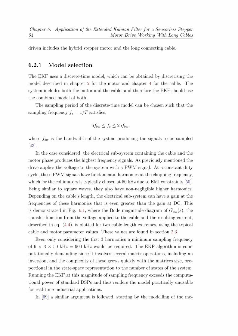
54Chapter 6. Application of the Extended Kalman Filter for a Sensorless Stepper
Motor Drive Working With Long Cables
driven includes the hybrid stepper motor and the long connecting cable.
6.2.1 Model selection
The EKF uses a discrete-time model, which can be obtained by discretising the
model described in chapter 2 for the motor and chapter 4 for the cable. The
system includes both the motor and the cable, and therefore the EKF should use
the combined model of both.
The sampling period of the discrete-time model can be chosen such that the
sampling frequency fs = 1/T satisfies:
6fbw ≤ fs ≤ 25fbw,
where fbw is the bandwidth of the system producing the signals to be sampled
[43].
In the case considered, the electrical sub-system containing the cable and the
motor phase produces the highest frequency signals. As previously mentioned the
drive applies the voltage to the system with a PWM signal. At a constant duty
cycle, these PWM signals have fundamental harmonics at the chopping frequency,
which for the collimators is typically chosen at 50 kHz due to EMI constraints [50].
Being similar to square waves, they also have non-negligible higher harmonics.
Depending on the cable’s length, the electrical sub-system can have a gain at the
frequencies of these harmonics that is even greater than the gain at DC. This
is demonstrated in Fig. 6.1, where the Bode magnitude diagram of Gcm(s), the
transfer function from the voltage applied to the cable and the resulting current,
described in eq. (4.4), is plotted for two cable length extremes, using the typical
cable and motor parameter values. These values are found in section 2.3.
Even only considering the first 3 harmonics a minimum sampling frequency
of 6 × 3 × 50 kHz = 900 kHz would be required. The EKF algorithm is com-
putationally demanding since it involves several matrix operations, including an
inversion, and the complexity of those grows quickly with the matrices size, pro-
portional in the state-space representation to the number of states of the system.
Running the EKF at this magnitude of sampling frequency exceeds the computa-
tional power of standard DSPs and thus renders the model practically unusable
for real-time industrial applications.
In [69] a similar argument is followed, starting by the modelling of the mo-

6.2. The proposed approach 55
Figure 6.1: Bode magnitude diagram of Gcm(s) for two cable length extremes
tor plus cable, with the approximation of the latter as a first order RLC stage,
leading to the conclusion that even though the proposal is correct and works in
simulation, it is not feasible to be implemented in a DSP platform due to the
high computational load implied.
For this reason, the use of the motor model alone in the EKF is considered
hereafter. Its electrical closed-loop bandwidth is typically at 1-2 kHz [50]. With
this bandwidth, a sampling frequency for the EKF of 6-50 kHz can be used, which
is much more reasonable for implementation on a DSP. In addition, the model is
simpler than including the cable.
Using the motor model alone in the EKF means that its inputs and mea-
surements are the motor-side voltages and currents respectively, which are not
directly available. The available information is on the drive side, as shown in Fig.
6.2.
A different current estimation approach is proposed, using dedicated adaptive
filters, which from the available drive side current measurements estimate the
motor side current.
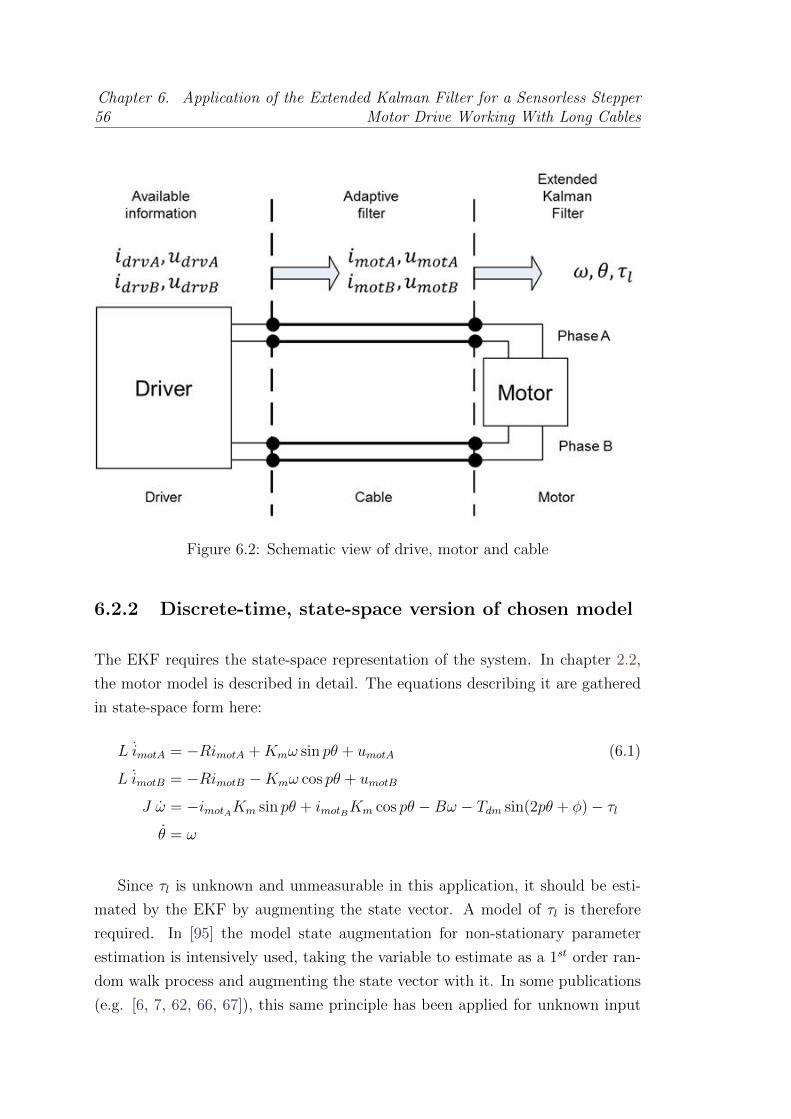
56Chapter 6. Application of the Extended Kalman Filter for a Sensorless Stepper
Motor Drive Working With Long Cables
Figure 6.2: Schematic view of drive, motor and cable
6.2.2 Discrete-time, state-space version of chosen model
The EKF requires the state-space representation of the system. In chapter 2.2,
the motor model is described in detail. The equations describing it are gathered
in state-space form here:
L imotA = −RimotA +Kmω sin pθ + umotA (6.1)
L imotB = −RimotB −Kmω cos pθ + umotB
J ω = −imotAKm sin pθ + imotBKm cos pθ −Bω − Tdm sin(2pθ + φ)− τlθ = ω
Since τl is unknown and unmeasurable in this application, it should be esti-
mated by the EKF by augmenting the state vector. A model of τl is therefore
required. In [95] the model state augmentation for non-stationary parameter
estimation is intensively used, taking the variable to estimate as a 1st order ran-
dom walk process and augmenting the state vector with it. In some publications
(e.g. [6, 7, 62, 66, 67]), this same principle has been applied for unknown input

6.2. The proposed approach 57
estimation, modelling the load torque in a hybrid stepper motor as:
dτldt
= d(t), (6.2)
where d(t) is a zero-mean, normally distributed, white noise. This same approach
is followed.
The EKF requires discrete-time state transition and measurement equations
of the system whose states are going to be estimated. Since only the model of the
stepper motor is going to be used in the algorithm, these can be obtained from
equations (6.1) and (6.2), resulting in the continuous-time state-space represen-
tation of the system represented in (6.3).
x1 = a11x1 + a13x3 sin px4 + u1 (6.3)
x2 = a22x2 + a23x3 cos px4 + u2
x3 = a31x1 sin px4 + a23x2 cos px3 + a33x3 + a34 sin(2px4 + φ) + a35x5
x4 = x3
x5 = d(t)
where xi with i = 1, ..., 5 are the state vector terms
x(t) =
imotA
imotB
ω
θ
τl
, (6.4)
u1 and u2 are the input vector terms
u(t) =
[umotA
umotB
](6.5)
and ai,j are the coefficients
a11 = −RL
a13 = −KmL
a22 = −RL
a23 = KmL
a31 = −KmJ
a32 = KmJ
a33 = −BJ
a34 = −TdmJ
a31 = −1J.
(6.6)
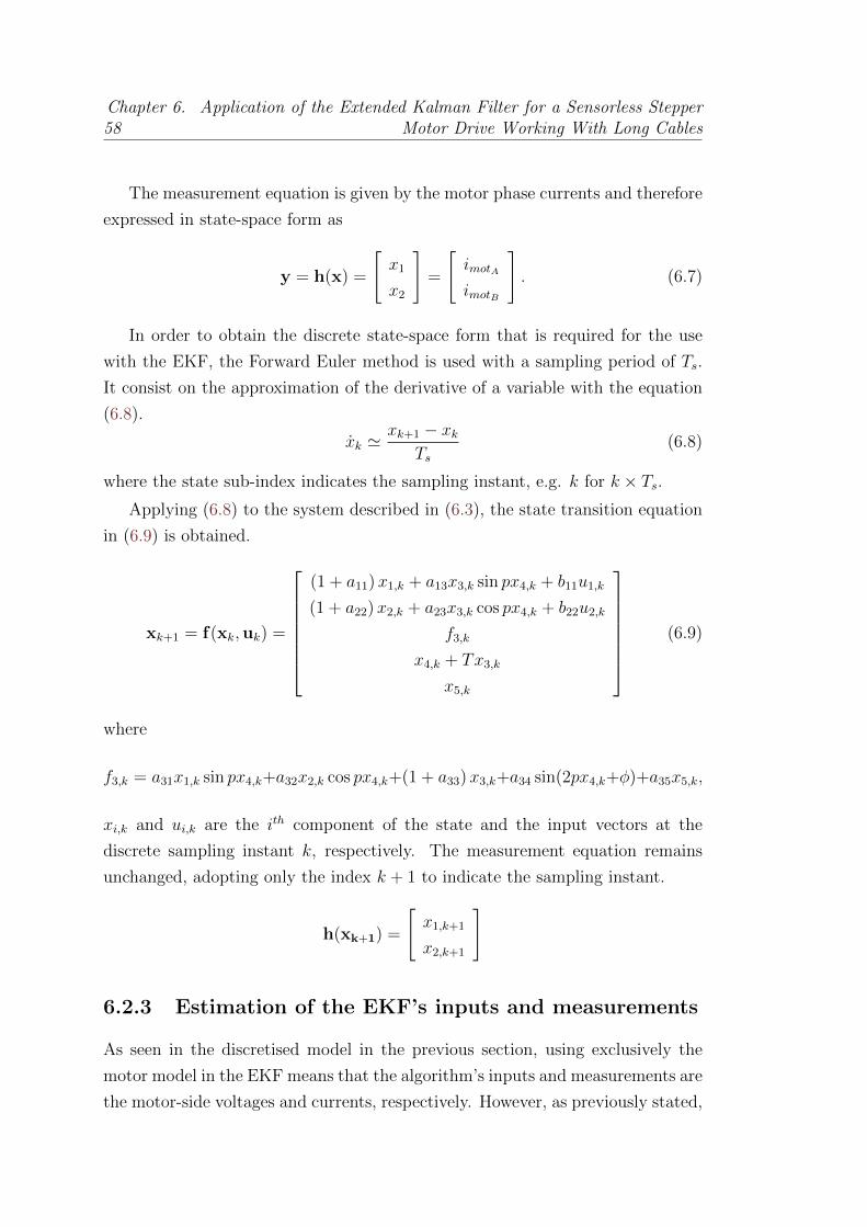
58Chapter 6. Application of the Extended Kalman Filter for a Sensorless Stepper
Motor Drive Working With Long Cables
The measurement equation is given by the motor phase currents and therefore
expressed in state-space form as
y = h(x) =
[x1
x2
]=
[imotAimotB
]. (6.7)
In order to obtain the discrete state-space form that is required for the use
with the EKF, the Forward Euler method is used with a sampling period of Ts.
It consist on the approximation of the derivative of a variable with the equation
(6.8).
xk 'xk+1 − xk
Ts(6.8)
where the state sub-index indicates the sampling instant, e.g. k for k × Ts.Applying (6.8) to the system described in (6.3), the state transition equation
in (6.9) is obtained.
xk+1 = f(xk,uk) =
(1 + a11)x1,k + a13x3,k sin px4,k + b11u1,k
(1 + a22)x2,k + a23x3,k cos px4,k + b22u2,k
f3,k
x4,k + Tx3,k
x5,k
(6.9)
where
f3,k = a31x1,k sin px4,k+a32x2,k cos px4,k+(1 + a33)x3,k+a34 sin(2px4,k+φ)+a35x5,k,
xi,k and ui,k are the ith component of the state and the input vectors at the
discrete sampling instant k, respectively. The measurement equation remains
unchanged, adopting only the index k + 1 to indicate the sampling instant.
h(xk+1) =
[x1,k+1
x2,k+1
]
6.2.3 Estimation of the EKF’s inputs and measurements
As seen in the discretised model in the previous section, using exclusively the
motor model in the EKF means that the algorithm’s inputs and measurements are
the motor-side voltages and currents, respectively. However, as previously stated,

6.2. The proposed approach 59
these signals are not directly available in ordinary operation since measurements
can only be made on the drive-side of the cable.
The cable’s length, together with the relatively high chopping frequency of the
PWM voltage signals, makes it act as a transmission line. This line’s principal
characteristics are those of a series resistor with a shunt capacitor across the
motor’s polarities. The capacitive behaviour induces large oscillations in the
current at the cable’s drive-end and, similarly, oscillations in the voltage at the
cable’s motor-end, both with frequency components close to those of the PWM’s
harmonics.
These oscillations on the drive-side current and motor-side voltage can be
viewed as measurement and process noise, respectively, however the properties of
these noises do not satisfy the assumption (A1) required for the EKF, as shown
in chapter 5.3. This means that applying the Kalman filter on these signals is
unlikely to produce reliable state estimates. Therefore, noise whitening filters are
required.
The approach proposed is to use cable length adaptive estimators on the
drive-side data. These estimators rely on the fact that the motor’s dynamics
are much slower than those of the cables. As previously discussed, the closed-
loop bandwidth of the motor’s phase currents is approximately 1-2 kHz. Since the
motor electrical dynamics can be considered linear and time-invariant (LTI), with
the back-emf acting as a slowly-varying disturbance, only frequency components
of the motor phase voltages and currents within approximately a decade of this
bandwidth significantly affect the current magnitude.
We are, therefore, only interested in estimating components of the motor-
side signals within this lower range of frequencies. Since the cable can also be
considered to be an LTI system in the frequency and signal amplitude ranges of
use, it is possible to consider only the components of the drive-side signals at
frequencies within this range. In the following subsections the estimators used to
evaluate the motor-side currents and effective voltages are described.
Motor-side current estimator
Using the two port T-net cable model with the motor phase seen in chapter 4, Fig.
4.1, a transfer function between the drive-side current Idrvj(s) and the motor-side

60Chapter 6. Application of the Extended Kalman Filter for a Sensorless Stepper
Motor Drive Working With Long Cables
current Imotj(s) of phase j can be calculated, the estimator Hest(s):
Hest(s) =Imotj(s)
Idrvj(s)=
Zt12(s)
Zt2(s) + Zt12(s) + Zmot(s). (6.10)
In this expression part of the the Back-EMF’s contribution to Imotj(s) is neglected.
Nevertheless, as shown in [50], this contribution is negligible at standard motor
operating speeds.
In the form expressed in (6.10), this transfer function is not directly imple-
mentable due to the transcendental hyperbolic functions leading to an infinite
number of poles and zeros. Nonetheless, in the reduced frequency range of inter-
est, it is possible to obtain an approximation, Hest(s), to this transfer function
using a 2nd order Pade approximant. In Fig. 6.3 this approximation is plotted
for two extremes of the cable length range. In the upper plot, superposition of
the magnitudes can be appreciated, whilst for the bottom plot the magnitudes
are nearly superimposed up to approximately 20 kHz.
The stability of this estimator is obviously of great importance. It is, however,
difficult to prove analytically the filter’s stability for all cable lengths due to
the complexity of the coefficient expressions found via the Pade approximation
procedure. Nonetheless, an empirical assessment has been made by evaluating
the poles of Hest(s) over a grid of 100 cable lengths selected randomly from a
uniform distribution in the range of interest i.e. [0.1 km, 1 km]. The poles of
Hest(s) form a complex conjugate pair, their real parts are therefore the same.
This value is plotted for each cable length in Fig. 6.4.
It can be seen that the real parts of the poles are all negative, ensuring, at
least for the cable lengths considered, that Hest(s) is stable. Furthermore the
values vary smoothly, despite the use of randomly distributed cable lengths, so it
is unlikely that filters evaluated at inter-sample cable lengths would be unstable.
Since Hest(s) is cable length adaptive, it is logical to realise it as a digital filter
Gest(z) whose coefficients can be easily adapted to the cable used. The filter
is, therefore, discretised using a Tustin transformation, chosen for its stability
preserving property and good matching in the frequency domain. The sampling
frequency used to discretise Hest(s) is normally higher than that used by the
EKF, since its bandwidth can typically be higher, as seen in Fig. 6.3.

6.2. The proposed approach 61
Figure 6.3: The approximation Hest(s) (dashed) and the exact expression Hest(s)(solid) for two cable lengths.
Figure 6.4: Real part of Hest(s)’s poles over a range of cable lengths
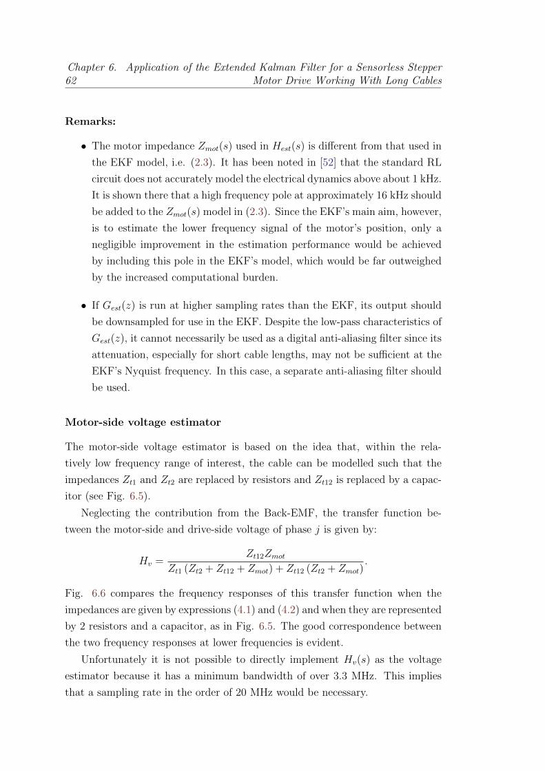
62Chapter 6. Application of the Extended Kalman Filter for a Sensorless Stepper
Motor Drive Working With Long Cables
Remarks:
• The motor impedance Zmot(s) used in Hest(s) is different from that used in
the EKF model, i.e. (2.3). It has been noted in [52] that the standard RL
circuit does not accurately model the electrical dynamics above about 1 kHz.
It is shown there that a high frequency pole at approximately 16 kHz should
be added to the Zmot(s) model in (2.3). Since the EKF’s main aim, however,
is to estimate the lower frequency signal of the motor’s position, only a
negligible improvement in the estimation performance would be achieved
by including this pole in the EKF’s model, which would be far outweighed
by the increased computational burden.
• If Gest(z) is run at higher sampling rates than the EKF, its output should
be downsampled for use in the EKF. Despite the low-pass characteristics of
Gest(z), it cannot necessarily be used as a digital anti-aliasing filter since its
attenuation, especially for short cable lengths, may not be sufficient at the
EKF’s Nyquist frequency. In this case, a separate anti-aliasing filter should
be used.
Motor-side voltage estimator
The motor-side voltage estimator is based on the idea that, within the rela-
tively low frequency range of interest, the cable can be modelled such that the
impedances Zt1 and Zt2 are replaced by resistors and Zt12 is replaced by a capac-
itor (see Fig. 6.5).
Neglecting the contribution from the Back-EMF, the transfer function be-
tween the motor-side and drive-side voltage of phase j is given by:
Hv =Zt12Zmot
Zt1 (Zt2 + Zt12 + Zmot) + Zt12 (Zt2 + Zmot).
Fig. 6.6 compares the frequency responses of this transfer function when the
impedances are given by expressions (4.1) and (4.2) and when they are represented
by 2 resistors and a capacitor, as in Fig. 6.5. The good correspondence between
the two frequency responses at lower frequencies is evident.
Unfortunately it is not possible to directly implement Hv(s) as the voltage
estimator because it has a minimum bandwidth of over 3.3 MHz. This implies
that a sampling rate in the order of 20 MHz would be necessary.

6.2. The proposed approach 63
5
Fig. 4. Real part of Hest(s)’s poles over a range of cable lengths
r- rh2
rh2
-rZmot
l-+6
r r
6
ch
idrvj imotj
udrvj umotj
ej
Fig. 5. Low frequency cable model connected to motor phase
typically be higher, see Fig. 3.Remarks:- The Zmot(s) used in Hest(s) is different from that usedin the EKF model i.e. Eq. (5). It has been noted in [7]that the standard RL circuit does not accurately model theelectrical dynamics above about 1 kHz. It is shown there thata high frequency pole at approximately 16 kHz should beadded to the Zmot(s) model in Eq. (5). Since the EKF’s mainaim, however, is to estimate the lower frequency signal ofthe motor’s position, only a negligible improvement in theestimation performance would be achieved by including thispole in the EKF’s model, which would be far outweighed bythe increased computational burden.- If Gest(z) is run at higher sampling rates than the EKF, itsoutput should be downsampled for use in the EKF. DespiteGest(z)’s low-pass characteristics, it cannot necessarily beused as a digital anti-aliasing filter since its attenuation,especially for short cable lengths, may not be sufficient at theEKF’s Nyquist frequency. In this case, a separate anti-aliasingfilter should be used. This can either be implemented as ananalog filter or, if processing power allows, as a digital filter.
2) Motor-side voltage estimator: The motor-side voltageestimator is based on the idea that, within the relatively lowfrequency range of interest, the cable can be modelled suchthat the impedances Zt1 and Zt2 are replaced by resistors andZt12 is replaced by a capacitor, see Fig. 5. Neglecting thecontribution from the Back-EMF, the transfer function betweenthe motor-side and drive-side voltage of phase j is given by:
Hv =Zt12Zmot
Zt1 (Zt2 + Zt12 + Zmot) + Zt12 (Zt2 + Zmot).
Fig. 6. Comparison of the frequency responses of Hv(s) using the completeimpedance expressions and the approximation, for two cable length extremes
Fig. 6 compares the frequency responses of this transferfunction when the impedances are given by expressions (8)and (9) and when they are represented by 2 resistors anda capacitor, as in Fig. 5. The good correspondence betweenthe two frequency responses at lower frequencies is evident.Unfortunately it is not possible to directly implement Hv(s)as the voltage estimator because it can be shown to have aminimum bandwidth of over 3.3 MHz. This implies that asampling rate in the order of 20 MHz would be necessary.
Nonetheless, using the circuit approximation, it is stillpossible to obtain an estimate of the motor-side voltage sincethe following relation holds:
umotj ,k = udrvj ,k −rh
2
(imotj ,k + idrvj ,k
). (12)
It should be remembered that this expression holds for the lowfrequency model depicted in Fig. 5. The signals in it, therefore,refer to signals which are limited to the band of frequenciesfor which the model is valid. Low-pass filtered versions ofudrvj ,k, imotj ,k and idrvj ,k are, therefore, required. Since thecomputed control action is equal to the average voltage overa PWM chopping period, it can be directly used as a low-pass filtered version of udrvj ,k. Using this value removesthe need to increase the drive’s electronic complexity withdedicated circuitry for the measurement of the instantaneous,AC voltage signals. The control algorithm for the drive’s H-bridges should, nonetheless, be carefully designed to ensurethat the desired average voltages are applied. Moreover, ameasurement of the slowly varying, DC bridge supply voltageshould be available in order to calculate correctly the PWMsignals’ duty cycles. This measurement is typically availablefor drive diagnostics so the drive’s complexity is not furtherincreased. imotj ,k is available in its estimated form fromthe previously presented motor-side current estimator. It willhave a bandwidth equal to the current controller’s closed-loopbandwidth, which will typically be easily within the validfrequency band. idrvj ,k can contain non-negligible frequencycomponents at the PWM harmonic frequencies, as seen in Fig.
Figure 6.5: Low frequency cable model connected to motor phase
Figure 6.6: Comparison of the frequency responses of Hv(s) using the completeimpedance expressions and the approximation, for two cable length extremes
64Chapter 6. Application of the Extended Kalman Filter for a Sensorless Stepper
Motor Drive Working With Long Cables
Nonetheless, using the circuit approximation, it is still possible to obtain an
estimate of the motor-side voltage since the following relation holds:
umotj ,k = udrvj ,k −rh
2
(imotj ,k + idrvj ,k
). (6.11)
It should be remembered that this expression holds for the low frequency model
depicted in Fig. 6.5. The signals in it, therefore, refer to signals which are limited
to the band of frequencies for which the model is valid. Low-pass filtered versions
of udrvj ,k, imotj ,k and idrvj ,k are, therefore, required.
Since the computed control action is equal to the average voltage over a PWM
chopping period, it can be directly used as a low-pass filtered version of udrvj ,k.
Using this value removes the need to increase the drive’s electronic complexity
with dedicated circuitry for the measurement of the instantaneous, AC voltage
signals. The control algorithm for the drive’s H-bridges should, nonetheless, be
carefully designed to ensure that the desired average voltages are applied.
Moreover, a measurement of the slowly varying, DC bridge supply voltage
should be available in order to calculate correctly the PWM signals’ duty cy-
cles. This measurement is typically available for drive diagnostics so the drive’s
complexity is not further increased.
imotj ,k is available in its estimated form from the previously presented motor-
side current estimator. It has a bandwidth equal to the current controller’s closed-
loop bandwidth, which is typically easily within the valid frequency band.
idrvj ,k can contain non-negligible frequency components at the PWM harmonic
frequencies, as seen in Fig. 6.1, which violate the model’s assumptions. Nonethe-
less these frequencies are greater than the frequency band of interest so they
can be filtered out either analogically or digitally before the signal is used in the
estimator expression (6.11).
Remark:
• The additional computing resources required for the above described esti-
mators is less than would be needed for an EKF model incorporating even
the low frequency cable dynamics. This is because the DSP is optimised to
run Infinite Impulse Response (IIR) filters, such as Gest(z), very efficiently,
whereas the matrix manipulations required by the EKF are computation-
ally very costly, especially for large matrices. The EKF incorporating these

6.3. Simulation 65
dynamics would require 7 states and a more complex measurement state
equation making it practically infeasible.
6.3 Simulation
In this section the effectiveness of the proposed method is demonstrated via sim-
ulation studies.
6.3.1 Simulator description
In order to validate the proposed approach, a realistic model of the drive-cable-
motor system is required. For this purpose a high order, nonlinear model is
developed using Mathworks’s SimulinkTM. The model’s main blocks, represented
in Fig. 6.7, are
Reference generators: Generate the two phases’ current references based on
the desired stepping rate and mode. In the simulations full step, 1 phase on
mode is used, with an RMS current reference value of 2 A. Full step mode
corresponds to rotor steps of 1.8 degrees, as the modelled motor has p = 50.
Current controllers: Discrete-time linear PI current controllers, one per phase,
operating at a sampling rate of 25 kHz and giving a closed-loop bandwidth
of 1 kHz are implemented.
PWM: Control action modulators using a 120 V DC supply voltage, which
compensates the voltage drops over the longest cable and allows the desired
bandwidth to be achieved. It operates at a 50 kHz chopping frequency to
prevent low frequency EMI emissions and reduce current ripple.
7
Current ReferenceGenerators
- l-+
−Current
Controllers--
udrv
PWM - Cable + MotorElectrical System
- MotorMechanical System
-θ
Motor-sideCurrent Estimators
-
Drive-side CurrentMeasurement System
imot idrv
Motor-sideVoltage Estimators
umot
6
EKFx
Fig. 7. Simulation model structure
lead to a reduced number of decision variables and ρ becomesρ = [Q11,22, Q33, Q44, Q55, R11,22]
T .Initial values are required for x0|0 and P0|0. The former is
taken as the zero vector. The latter is set equal to α2Q withα2 = 10, though it was found that the EKF’s performance wasrelatively insensitive to the exact choice of α.
C. Simulation resultsThe model is used to generate two data sets with indepen-
dent noise realisations for 10 cable lengths. Both data sets usea stepping rate of 20 step/s. Moreover the applied load torquehas the form of a pulse stepping from 0.7 Nm to 1.4 Nm andback; these values were chosen as representative of a real loadtorque experienced in particle accelerator positioning systems.The first data set is used as the training set to estimate thecovariance matrices and the second as a validation set. Thetuning procedure is used to tune EKFs for each cable length.The weighting matrix is taken as W = diag([1, 1, 0, 10, 5]),which is motivated by the relevant importance placed on eachstate’s estimation. Since the motor’s angular position is ofkey importance it is given the highest weighting. Typicallya good angular speed estimation is achieved when goodposition estimation occurs so it is not necessary to weight thisspecifically. The load torque estimation is of lower importancethan that of the position so is weighted more lightly. Finallysince the drive-side currents are already accurately estimatedusing their dedicated estimators, their estimation by the EKFcan be weighted less heavily. In fact with little parametermismatch in the EKF’s model, the estimation performanceis relatively insensitive to the weighting used. However, aswill be seen later, when parameter uncertainty is significant,the weighting of the most important state plays a key role inachieving its good estimation.
The true motor angular position and load torque are acquiredduring the simulation for use in the tuning procedure. Inorder for the procedure to be realistic, measurement noise isadded to these acquisitions. In the angular position’s case, arandom process that is uniformly distributed in the interval[-9.5874 ×10⁻⁵, 9.5874 ×10⁻⁵] rad is added. This choiceis based on the quantization error occurring in a 32768lines/turn rotary encoder. The load torque noise is a normallydistributed, zero mean process with a variance of 9 ×10⁻⁶(Nm)2, based on experimental testbench data. Fig. 8 showsthe EKF’s state estimates for a 1 km cable. It can be seen thatthe EKF functions properly and tracks the states well with themaximum Root Mean Square (RMS) angle estimation errorover the cable lengths being 0.0878 mechanical degrees.
Fig. 8. True (dashed) and estimated (solid) states for a 1 km cable; nearsuperposition for first 4 states (imotA , imotB , ω and θ)
In order to make the simulation more realistic, uniformlydistributed parameter mismatch is considered in all the pa-rameters of the EKF and motor-side signal estimators. Theith parameter is, therefore, randomly chosen in the interval0.85ρ0i ≤ ρi ≤ 1.15ρ0i , where ρ0i is the true value. The RMSpercentage parameter mismatch over all the parameters usedin the EKF and motor-side signal estimators is of 9.34 %.Fig. 9 shows the EKF’s state estimates for a 1 km cablewith parameter mismatch. It can be seen that the positionestimation is still good, in spite of the parameter mismatch.The load torque tracking, however, is poor, compensating forthe modelling error in order to achieve good position tracking,since this is the most heavily weighted state in the tuningprocedure. The RMS of the angle estimation errors achievedon the validation set of data at each length using the EKFtuned for that length on the estimation data set are evaluated.The same mismatch percentage for each parameter is used forall cable lengths. The results are presented in Fig. 10. It canbe seen that the worse case tracking, in terms of the RMS and
Figure 6.7: Simulation model structure
66Chapter 6. Application of the Extended Kalman Filter for a Sensorless Stepper
Motor Drive Working With Long Cables
Cable and Motor electrical system model: Continuous-time, electrical sys-
tem model using the parameter values in section 2.3. The cable model’s hy-
perbolic terms are approximated by 4th order balanced Pade approximants
[47, 80], allowing the cable dynamics to be approximated well up to 150
kHz over all cable lengths. The motor model uses the high frequency pole
to model its high frequency dynamics accurately.
Motor mechanical system model: Continuous-time mechanical system model
with parameter values given in section 2.3.
A load torque is applied to the rotor.
Drive-side current measurement system: Incorporates analog anti-aliasing
filters, one per phase, taken as 2nd order Butterworth filters with band-
widths of 7 kHz. The cut-off frequency and order are chosen to achieve a
trade-off between passing non-negligible frequency components of the cur-
rents which could affect the EKF estimation accuracy, yet acting as effective
anti-aliasing filters and sufficiently attenuating components due to distur-
bances and noise above the Nyquist frequency of the EKF’s sampling rate.
This trade-off is valid since at 7 kHz the electrical system’s closed-loop
gain is approximately -17 dB, which can be considered negligible, and the
anti-aliasing filters’ gain at the Nyquist frequency is -10.5 dB, which can
be considered sufficient suppression (see [42]). The low order filter has also
been chosen to reduce the phase lag it introduces. It is also in this block
that measurement noise is injected into the simulation. This noise has the
following characteristics:
nk ∈ N (0,Rn) where Rn = diag([0.052, 0.052])A2,
and is injected before the anti-aliasing filter.
Motor-side current estimators: Gest(z) filtering the measured drive-side cur-
rents at a sampling frequency of 500 kHz.
Motor-side voltage estimators: Based on Eq. (6.11) and using the control
actions as the drive-side voltages, the downsampled outputs of the anti-
aliasing filters as the drive-side currents and the downsampled outputs of
Gest(z) as the motor-side currents.
6.3. Simulation 67
Extended Kalman Filter: The EKF operates at the same sampling frequency
as the current controllers, i.e. 25 kHz. It is coded according to the steps in
Equations (5.2)-(5.4).
6.3.2 EKF tuning method
In order to have a well-performing EKF it is necessary to provide the algorithm
with the process noise covariance matrix Qk and the measurement noise covari-
ance matrix Rk. The noise processes, whose covariances are represented by Qk
and Rk, contain contributions from various sources including:
• unmodelled dynamics, which are modelled in the full Simulink model but
not in the reduced order EKF
• measurement noise arising from the measurement process
• estimation errors in the voltage and current estimates
In order to find appropriate values for Qk and Rk, which are cable length de-
pendent, an optimisation approach is used which solves the following optimisation
problem:
ρN = arg minρ
N−1∑
k=0
εT (k,ρ)Wε(k,ρ)
such that
ρ ≥ 0 and Equations (5.2)− (5.4)
where
ρ = [Qk,Rk]
and
ε(k,ρ) = xm,k − x(k|k,ρ),
xm,k is a vector of measured states at instant k, W is a weighting matrix and
x(k|k,ρ) is the aposteriori estimate (5.3) produced by the EKF using parameters
ρ.
This approach assumes that some or all of the state variables can be measured
to provide the training set of data required for the proposed tuning approach.
This, of course, is possible in simulation. It is, also, reasonable for the real
application, where a one-off experiment could be performed with the necessary
instrumentation.
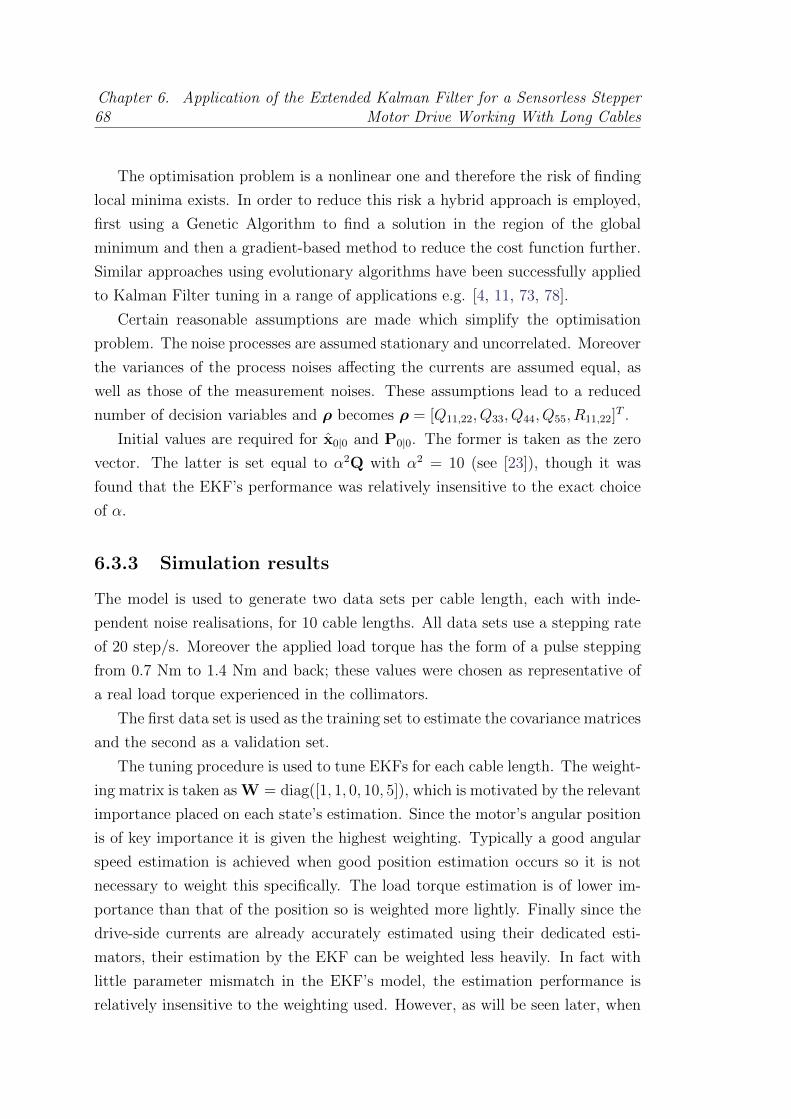
68Chapter 6. Application of the Extended Kalman Filter for a Sensorless Stepper
Motor Drive Working With Long Cables
The optimisation problem is a nonlinear one and therefore the risk of finding
local minima exists. In order to reduce this risk a hybrid approach is employed,
first using a Genetic Algorithm to find a solution in the region of the global
minimum and then a gradient-based method to reduce the cost function further.
Similar approaches using evolutionary algorithms have been successfully applied
to Kalman Filter tuning in a range of applications e.g. [4, 11, 73, 78].
Certain reasonable assumptions are made which simplify the optimisation
problem. The noise processes are assumed stationary and uncorrelated. Moreover
the variances of the process noises affecting the currents are assumed equal, as
well as those of the measurement noises. These assumptions lead to a reduced
number of decision variables and ρ becomes ρ = [Q11,22, Q33, Q44, Q55, R11,22]T .
Initial values are required for x0|0 and P0|0. The former is taken as the zero
vector. The latter is set equal to α2Q with α2 = 10 (see [23]), though it was
found that the EKF’s performance was relatively insensitive to the exact choice
of α.
6.3.3 Simulation results
The model is used to generate two data sets per cable length, each with inde-
pendent noise realisations, for 10 cable lengths. All data sets use a stepping rate
of 20 step/s. Moreover the applied load torque has the form of a pulse stepping
from 0.7 Nm to 1.4 Nm and back; these values were chosen as representative of
a real load torque experienced in the collimators.
The first data set is used as the training set to estimate the covariance matrices
and the second as a validation set.
The tuning procedure is used to tune EKFs for each cable length. The weight-
ing matrix is taken as W = diag([1, 1, 0, 10, 5]), which is motivated by the relevant
importance placed on each state’s estimation. Since the motor’s angular position
is of key importance it is given the highest weighting. Typically a good angular
speed estimation is achieved when good position estimation occurs so it is not
necessary to weight this specifically. The load torque estimation is of lower im-
portance than that of the position so is weighted more lightly. Finally since the
drive-side currents are already accurately estimated using their dedicated esti-
mators, their estimation by the EKF can be weighted less heavily. In fact with
little parameter mismatch in the EKF’s model, the estimation performance is
relatively insensitive to the weighting used. However, as will be seen later, when
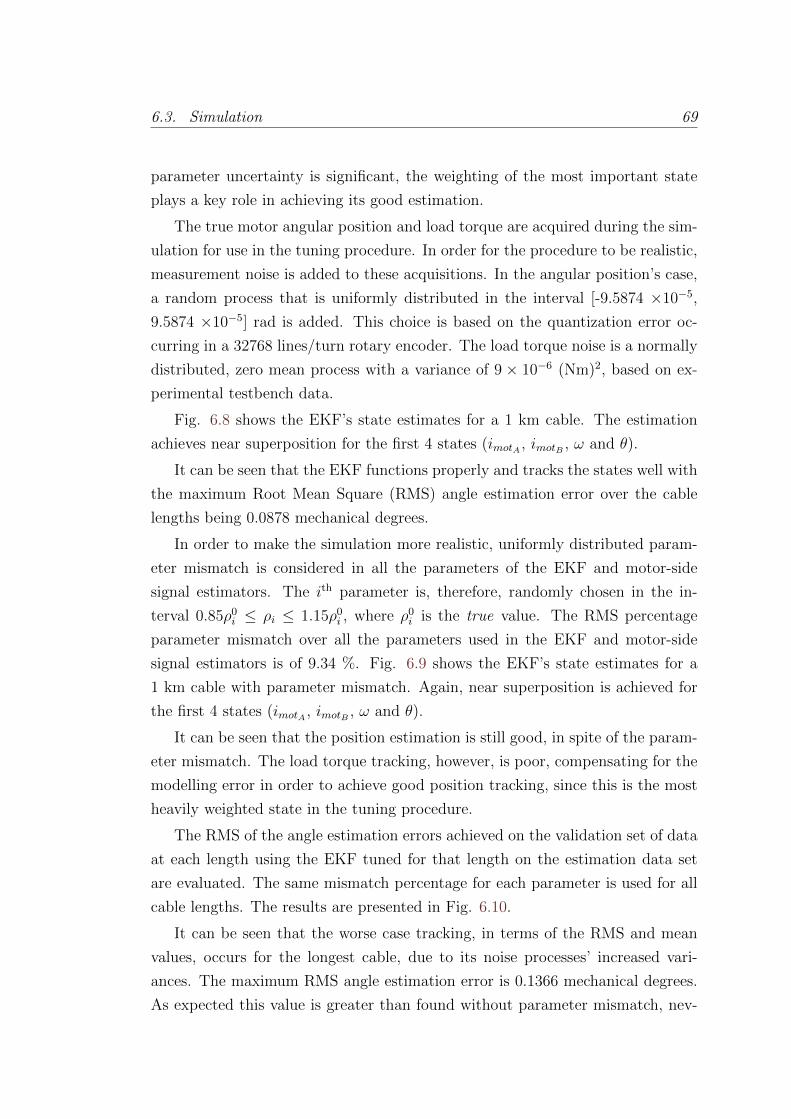
6.3. Simulation 69
parameter uncertainty is significant, the weighting of the most important state
plays a key role in achieving its good estimation.
The true motor angular position and load torque are acquired during the sim-
ulation for use in the tuning procedure. In order for the procedure to be realistic,
measurement noise is added to these acquisitions. In the angular position’s case,
a random process that is uniformly distributed in the interval [-9.5874 ×10⁻⁵,
9.5874 ×10⁻⁵] rad is added. This choice is based on the quantization error oc-
curring in a 32768 lines/turn rotary encoder. The load torque noise is a normally
distributed, zero mean process with a variance of 9 × 10⁻⁶ (Nm)2, based on ex-
perimental testbench data.
Fig. 6.8 shows the EKF’s state estimates for a 1 km cable. The estimation
achieves near superposition for the first 4 states (imotA , imotB , ω and θ).
It can be seen that the EKF functions properly and tracks the states well with
the maximum Root Mean Square (RMS) angle estimation error over the cable
lengths being 0.0878 mechanical degrees.
In order to make the simulation more realistic, uniformly distributed param-
eter mismatch is considered in all the parameters of the EKF and motor-side
signal estimators. The ith parameter is, therefore, randomly chosen in the in-
terval 0.85ρ0i ≤ ρi ≤ 1.15ρ0
i , where ρ0i is the true value. The RMS percentage
parameter mismatch over all the parameters used in the EKF and motor-side
signal estimators is of 9.34 %. Fig. 6.9 shows the EKF’s state estimates for a
1 km cable with parameter mismatch. Again, near superposition is achieved for
the first 4 states (imotA , imotB , ω and θ).
It can be seen that the position estimation is still good, in spite of the param-
eter mismatch. The load torque tracking, however, is poor, compensating for the
modelling error in order to achieve good position tracking, since this is the most
heavily weighted state in the tuning procedure.
The RMS of the angle estimation errors achieved on the validation set of data
at each length using the EKF tuned for that length on the estimation data set
are evaluated. The same mismatch percentage for each parameter is used for all
cable lengths. The results are presented in Fig. 6.10.
It can be seen that the worse case tracking, in terms of the RMS and mean
values, occurs for the longest cable, due to its noise processes’ increased vari-
ances. The maximum RMS angle estimation error is 0.1366 mechanical degrees.
As expected this value is greater than found without parameter mismatch, nev-
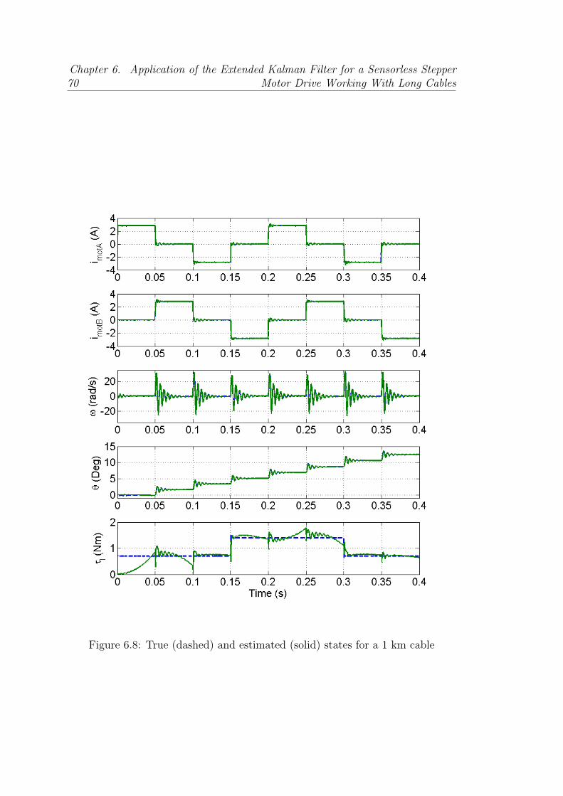
70Chapter 6. Application of the Extended Kalman Filter for a Sensorless Stepper
Motor Drive Working With Long Cables
Figure 6.8: True (dashed) and estimated (solid) states for a 1 km cable

6.3. Simulation 71
Figure 6.9: True (dashed) and estimated (solid) states for a 1 km cable withmismatch;
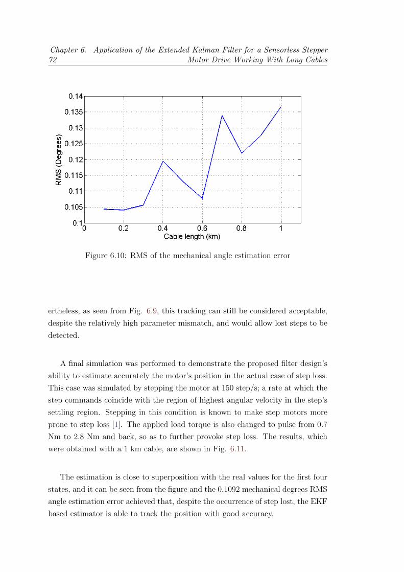
72Chapter 6. Application of the Extended Kalman Filter for a Sensorless Stepper
Motor Drive Working With Long Cables
Figure 6.10: RMS of the mechanical angle estimation error
ertheless, as seen from Fig. 6.9, this tracking can still be considered acceptable,
despite the relatively high parameter mismatch, and would allow lost steps to be
detected.
A final simulation was performed to demonstrate the proposed filter design’s
ability to estimate accurately the motor’s position in the actual case of step loss.
This case was simulated by stepping the motor at 150 step/s; a rate at which the
step commands coincide with the region of highest angular velocity in the step’s
settling region. Stepping in this condition is known to make step motors more
prone to step loss [1]. The applied load torque is also changed to pulse from 0.7
Nm to 2.8 Nm and back, so as to further provoke step loss. The results, which
were obtained with a 1 km cable, are shown in Fig. 6.11.
The estimation is close to superposition with the real values for the first four
states, and it can be seen from the figure and the 0.1092 mechanical degrees RMS
angle estimation error achieved that, despite the occurrence of step lost, the EKF
based estimator is able to track the position with good accuracy.
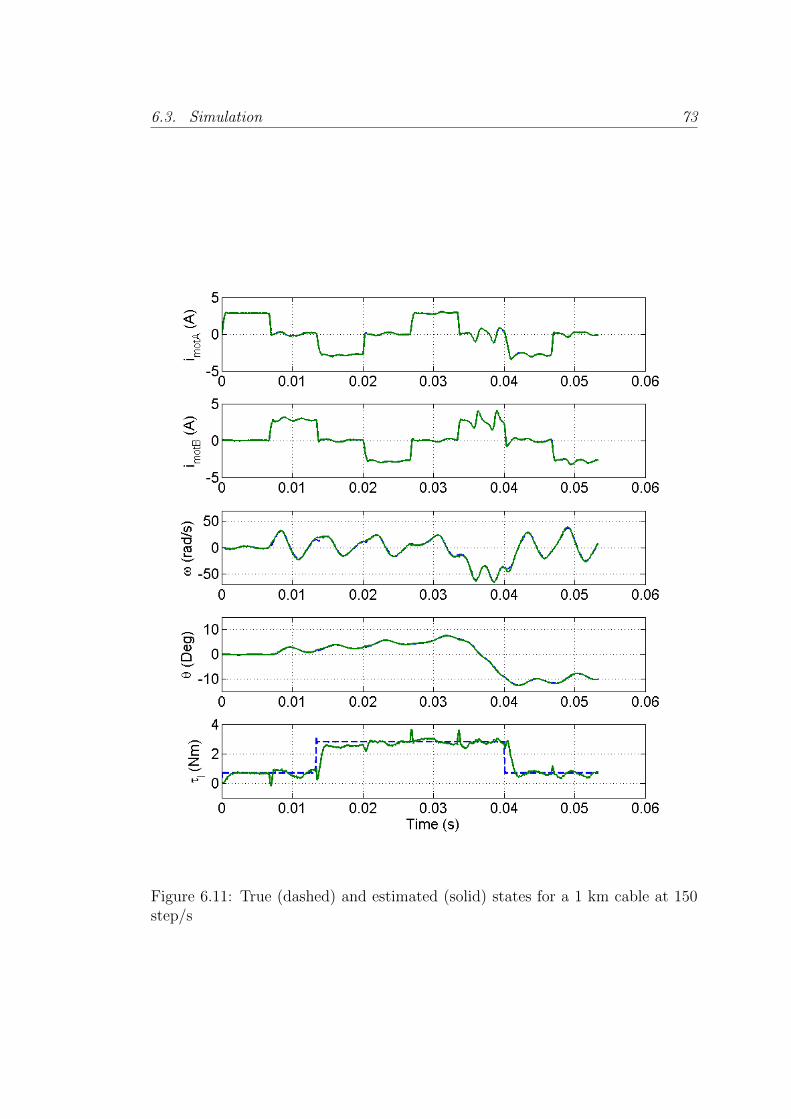
6.3. Simulation 73
Figure 6.11: True (dashed) and estimated (solid) states for a 1 km cable at 150step/s
74Chapter 6. Application of the Extended Kalman Filter for a Sensorless Stepper
Motor Drive Working With Long Cables
6.4 Experimental application to an LHC colli-
mator
The proposed estimation algorithm has been tested on a testbench based on a real
collimator and a Data Acquisition (DAQ) system developed ad hoc to compare
the estimation results with the real torque and position measured on a collimator
axis. The different parts used for this test are described and experimental results
are shown to validate the proposed approach.
6.4.1 Drive description
The drive used for this test has been described in chapter 4. The hardware
remains unchanged but in this occasion the EKF has been implemented in c code
for its use in real-time.
The motor-side voltage estimates can be estimated by Eq. (6.11). However,
due to Digital Signal Processor (DSP) processing power constraints, it is not
possible to obtain a low-pass filtered version of idrvj ,k and its direct, unfiltered
use in Eq. (6.11) results in aliasing occurring at the EKF sampling rate.
At the frequencies of interest, those which affect the EKF estimation perfor-
mance, the following approximation is done:
idrvj ,k ≈ imotj ,k (6.12)
And therefore (6.11) can be written as:
umotj ,k = udrvj ,k − rhimotj ,k (6.13)
Finally, based on this result, the cable resistance can be lumped with that
of the motor so the EKF can directly use the control action as its input, saving
DSP operations, and the resistance used in the EKF model is the sum of that of
the motor and that of the cable.
The interrupt running the controller is now in charge as well of executing the
Kalman algorithm. The execution rate of this interrupt has been set to 25 kHz,
which is necessary in order to achieve good control when a closed-loop bandwidth
of 1-2 kHz is desired.
In this interrupt, the controller routine is executed first in order to fulfill the
6.4. Experimental application to an LHC collimator 75
real-time constraints. Then the Kalman filter algorithm is run and some system
diagnostics are performed. The EKF uses the estimated motor-side mean voltage
as its input, and the current estimated by the filter interrupt as its output. As
seen previously it estimates the motor states, i.e. the motor-side currents, angular
position, angular speed and the external torque applied to the shaft.
The code running the filter has been highly optimized in order to achieve the
desired interrupt rate of 25 kHz, for this some of the steps described in [16] have
been followed, as well as the tuning procedure proposed. This tuning procedure
differs from the one described in section 6.3.2 and allows the system parameters
to also be estimated, as well as the covariance matrices.
6.4.2 Test Setup Description
In order to test the estimation capabilities of the driver, it has been used on a
real LHC collimator. A vertical collimator is used for the tests. It consists of two
vertically movable jaws, each one driven by two stepper motors. Another stepper
motor is used to displace the collimator horizontally. The collimator is shown in
Fig. 6.12.
The five motors in the collimator are driven from a control rack, which controls
up to 3 collimators. The rack contains 2 National Instruments PXIs, one of them
running the Motor Drive Control (MDC) and the other one the Position Readout
and Survey (PRS); and the stepper motor drivers used to drive the motors in the
3 collimators. Details on the LHC collimators low level control system can be
found in [51].
For this experiment, one of the drivers in the rack was replaced by the devel-
oped driver to control one of the motors in the collimator, connecting it through
a 720 meters cable. A special test fixture, shown in Fig. 6.13, was created in
order to have real-time measurements of the motor position and the applied load
torque.
For the position measurement, a Sick Stegmann Coretech DRS60 encoder
was used, and its output signals are decoded by the DSCs Enhanced Quadrature
Encoder Pulse Module and used to increment a counter, whose value is directly
recorded. For the torque measurements, an NCTE Torque Sensor Series 2000
has been used. The output of this sensor is recorded with a LeCroy WaveRunner
oscilloscope.
For the synchronization of oscilloscope and driver acquisitions, a digital output

76Chapter 6. Application of the Extended Kalman Filter for a Sensorless Stepper
Motor Drive Working With Long Cables
Figure 6.12: LHC Vertical Collimator
Figure 6.13: Experimental test fixture
6.4. Experimental application to an LHC collimator 77
signal from the driver, toggling at the internal driver acquisition instants at 25
kHz, is also acquired by the oscilloscope. A 2.5 MHz sampling rate is used in
order to allow accurate offline detection of the synchronization signal edges to
within one hundredth of a sampling period. A schematic diagram of the test set
up is shown in Fig. 6.14.
These measurements are used for 2 different purposes: tuning the filter, since
it is necessary to have position and torque measurements to follow the procedure
described in [16], and validation of the EKF, where the Kalman filter is run in
the driver.
In the tuning mode, the control actions calculated by the digital controller
and the estimated motor-side currents were also acquired by the driver. In the
validation mode, the EKF estimates the load torque and position for comparison
purposes with the real values. The DSC can store over 2 seconds of data in the
external memory at the controller rate of 25 kHz. Once an acquisition is requested
from the driver through the serial communication, the trigger to start it is the
first step signal received.
6.4.3 Experimental Results
Tuning experiment
In order to tune the EKF it was necessary to obtain a training data set. This
acquisition was done using the DSP code in the tuning mode which acquires the
motor-side current estimates, the control actions and the encoder count value and
sends the synchronization signal to the scope for the load torque signal synchro-
nisation.
A movement of the collimator jaw from the out position towards the in/beam
position (positive mean speed) was requested at a rate of 20 steps/s, full step, 1
phase on mode. The stepping rate and mode, which is different from the standard
collimator operating configuration, is chosen in order to obtain signals which are
sufficiently rich in information in order to estimate the parameters. Using the
acquired data, the tuning procedure was run to obtain the system parameters
and noise covariance matrices, as required by the EKF. The estimated values can
be found in Table 6.1.
It should be mentioned that the estimated B value is very small. Sensitivity
tests have shown that its value can be increased by up to a factor of 106 with only
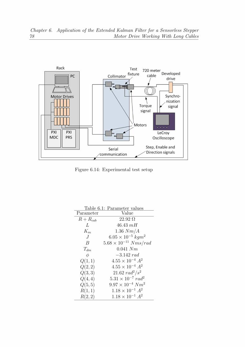
78Chapter 6. Application of the Extended Kalman Filter for a Sensorless Stepper
Motor Drive Working With Long Cables
Figure 6.14: Experimental test setup
Table 6.1: Parameter valuesParameter ValueR +Rcab 22.92 Ω
L 46.43 mHKm 1.36 Nm/AJ 6.05× 10⁻⁵ kgm2
B 5.68× 10⁻¹¹ Nms/radTdm 0.041 Nmφ −3.142 rad
Q(1, 1) 4.55× 10⁻⁴ A2
Q(2, 2) 4.55× 10⁻⁴ A2
Q(3, 3) 21.62 rad2/s2
Q(4, 4) 5.31× 10⁻⁷ rad2
Q(5, 5) 9.97× 10⁻⁴ Nm2
R(1, 1) 1.18× 10⁻¹ A2
R(2, 2) 1.18× 10⁻¹ A2
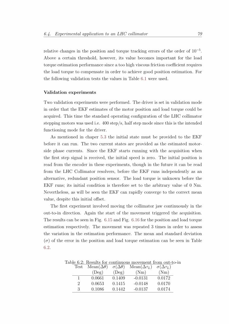
6.4. Experimental application to an LHC collimator 79
relative changes in the position and torque tracking errors of the order of 10−5.
Above a certain threshold, however, its value becomes important for the load
torque estimation performance since a too high viscous friction coefficient requires
the load torque to compensate in order to achieve good position estimation. For
the following validation tests the values in Table 6.1 were used.
Validation experiments
Two validation experiments were performed. The driver is set in validation mode
in order that the EKF estimates of the motor position and load torque could be
acquired. This time the standard operating configuration of the LHC collimator
stepping motors was used i.e. 400 step/s, half step mode since this is the intended
functioning mode for the driver.
As mentioned in chaper 5.3 the initial state must be provided to the EKF
before it can run. The two current states are provided as the estimated motor-
side phase currents. Since the EKF starts running with the acquisition when
the first step signal is received, the initial speed is zero. The initial position is
read from the encoder in these experiments, though in the future it can be read
from the LHC Collimator resolvers, before the EKF runs independently as an
alternative, redundant position sensor. The load torque is unknown before the
EKF runs; its initial condition is therefore set to the arbitrary value of 0 Nm.
Nevertheless, as will be seen the EKF can rapidly converge to the correct mean
value, despite this initial offset.
The first experiment involved moving the collimator jaw continuously in the
out-to-in direction. Again the start of the movement triggered the acquisition.
The results can be seen in Fig. 6.15 and Fig. 6.16 for the position and load torque
estimation respectively. The movement was repeated 3 times in order to assess
the variation in the estimation performance. The mean and standard deviation
(σ) of the error in the position and load torque estimation can be seen in Table
6.2.
Table 6.2: Results for continuous movement from out-to-inTest Mean(∆θ) σ(∆θ) Mean(∆τL) σ(∆τL)
(Deg) (Deg) (Nm) (Nm)1 0.0661 0.1409 -0.0131 0.01722 0.0653 0.1415 -0.0148 0.01703 0.1086 0.1442 -0.0137 0.0174
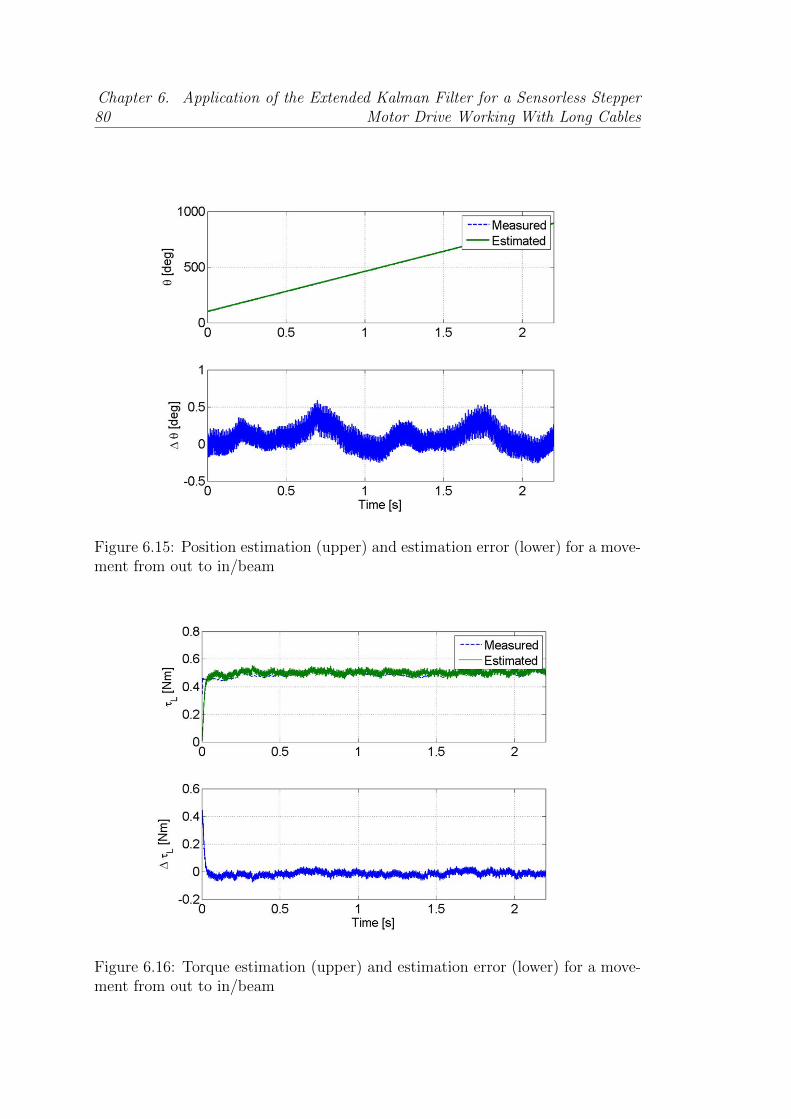
80Chapter 6. Application of the Extended Kalman Filter for a Sensorless Stepper
Motor Drive Working With Long Cables
Figure 6.15: Position estimation (upper) and estimation error (lower) for a move-ment from out to in/beam
Figure 6.16: Torque estimation (upper) and estimation error (lower) for a move-ment from out to in/beam
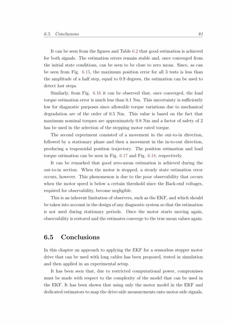
6.5. Conclusions 81
It can be seen from the figures and Table 6.2 that good estimation is achieved
for both signals. The estimation errors remain stable and, once converged from
the initial state conditions, can be seen to be close to zero mean. Since, as can
be seen from Fig. 6.15, the maximum position error for all 3 tests is less than
the amplitude of a half step, equal to 0.9 degrees, the estimation can be used to
detect lost steps.
Similarly, from Fig. 6.16 it can be observed that, once converged, the load
torque estimation error is much less than 0.1 Nm. This uncertainty is sufficiently
low for diagnostic purposes since allowable torque variations due to mechanical
degradation are of the order of 0.5 Nm. This value is based on the fact that
maximum nominal torques are approximately 0.8 Nm and a factor of safety of 2
has be used in the selection of the stepping motor rated torque.
The second experiment consisted of a movement in the out-to-in direction,
followed by a stationary phase and then a movement in the in-to-out direction,
producing a trapezoidal position trajectory. The position estimation and load
torque estimation can be seen in Fig. 6.17 and Fig. 6.18, respectively.
It can be remarked that good zero-mean estimation is achieved during the
out-to-in section. When the motor is stopped, a steady state estimation error
occurs, however. This phenomenon is due to the poor observability that occurs
when the motor speed is below a certain threshold since the Back-emf voltages,
required for observability, become negligible.
This is an inherent limitation of observers, such as the EKF, and which should
be taken into account in the design of any diagnostic system so that the estimation
is not used during stationary periods. Once the motor starts moving again,
observability is restored and the estimates converge to the true mean values again.
6.5 Conclusions
In this chapter an approach to applying the EKF for a sensorless stepper motor
drive that can be used with long cables has been proposed, tested in simulation
and then applied in an experimental setup.
It has been seen that, due to restricted computational power, compromises
must be made with respect to the complexity of the model that can be used in
the EKF. It has been shown that using only the motor model in the EKF and
dedicated estimators to map the drive-side measurements onto motor-side signals,
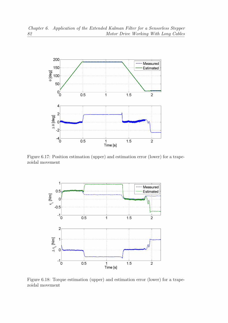
82Chapter 6. Application of the Extended Kalman Filter for a Sensorless Stepper
Motor Drive Working With Long Cables
Figure 6.17: Position estimation (upper) and estimation error (lower) for a trape-zoidal movement
Figure 6.18: Torque estimation (upper) and estimation error (lower) for a trape-zoidal movement
6.5. Conclusions 83
good position estimation can be achieved, in spite of model uncertainty.
For the experimental application, the EKF has been implemented in the drive
presented in chapter 4, a real-time platform based on a DSP. Furthermore a
testbench based around an LHC Collimator is presented in order to validate the
proposed drives position and load torque estimation capabilities. It is seen that
sufficiently good position and load torque estimation is possible to allow lost steps
to be detected and the mechanical degradation of the collimator to be assessed.
Chapter 7
Hybrid Stepper Motors Electrical
Model Extensions and Their
Application to Sensorless
Estimation
7.1 Introduction
In chapter 6, the Extended Kalman Filter was used for sensorless estimation of
a motor separated from the driver through a long cable. Even though the results
were satisfactory and the filter gives very useful estimations of rotor position and
load torque, some consistent mismatch between the expected currents when the
motor was being stepped and the real currents were observed.
In this chapter the limitations of the standard electrical model used for Hybrid
Stepper Motor control and observation are described to motivate the development
of an extended model, always with the goal in sight of its future application in a
real-time platform. This new extended model is one of the original contributions
of this thesis.
The evaluation of its performance and the computational cost for the different
models, in order to assess their usability in embedded control systems, are pre-
sented. An experiment on an ad-hoc developed testbench to assess the holding
torque current dependence and the coherency of the proposed model structure
for this type of motor data is carried out. Finally, in order to show the usefulness
for sensorless estimation of the proposed HSM model extensions, an Extended
84

7.1. Introduction 85
Kalman Filter is defined and experimentally evaluated in a real time control
application.
7.1.1 Standard electrical model revisited
The standard electrical motor model for a motor phase has already been pre-
sented in chapter 2.2, Eq. (2.1), it is rearranged and repeated as Eq. (7.1)
for convenience. Henceforth we will focus only on the motor part of the model
and therefore the currents and voltages will always be motor side, and the mot
subscript omitted.
uj(t) = Rij(t) + Lij(t) + ej(t) for j = A,B (7.1)
This equation can be rewritten in the form of Eq. (7.2), before splitting the
induced voltage into its separate components.
uj(t) = Rij(t) + vsj (t) for j = A,B (7.2)
where vsj (t) is the induced voltage for the standard electrical model.
The induced voltage is composed of two different sources. The first is the self-
induced voltage, produced by the derivative of the current in the phase winding.
The second is the back electromotive force, caused by the derivative of the flux
produced by the rotor permanent magnet crossing the phase winding as it rotates.
We can split it as in Eq. (7.3) leading back to the standard Eq. (7.1).
vsj (t) =dψsj (t)
dt=
d
dt
(Lij(t) + ψPMj (t)
)= L
dij(t)
dt+ ej(t) (7.3)
with ψsj being flux linkage of phase j, and the superscript s stands for the standard
model. The back electromotive forces, due to the relative movement of the rotor,
are described by:
eA(t) =d
dtψPMA (t) =
d
dtΨPM cos pθ(t) = −pΨPMω(t) sin pθ(t) (7.4)
and
eB(t) =d
dtψPMB (t) =
d
dtΨPM sin pθ(t) = pΨPMω(t) cos pθ(t). (7.5)
In these equations, ψPMj represents the flux linkage due to the permanent
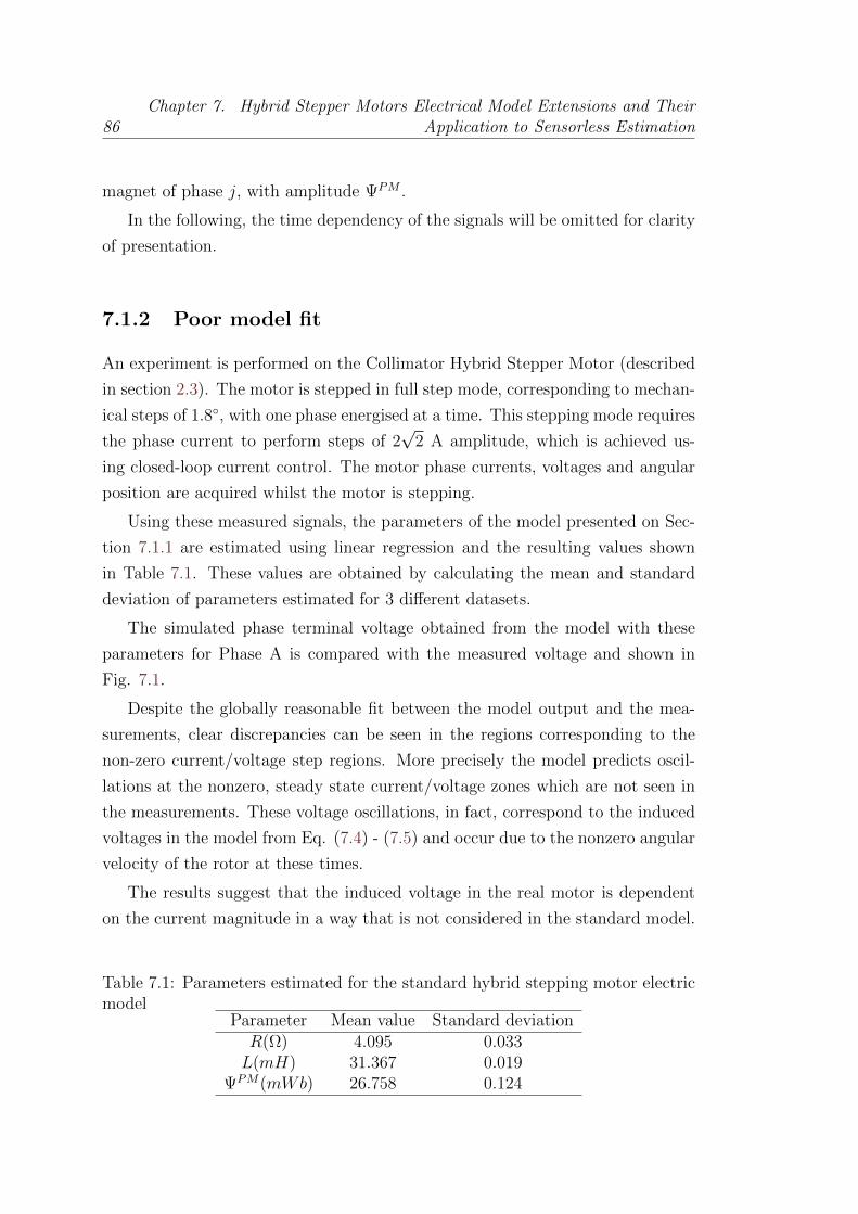
86Chapter 7. Hybrid Stepper Motors Electrical Model Extensions and Their
Application to Sensorless Estimation
magnet of phase j, with amplitude ΨPM .
In the following, the time dependency of the signals will be omitted for clarity
of presentation.
7.1.2 Poor model fit
An experiment is performed on the Collimator Hybrid Stepper Motor (described
in section 2.3). The motor is stepped in full step mode, corresponding to mechan-
ical steps of 1.8, with one phase energised at a time. This stepping mode requires
the phase current to perform steps of 2√
2 A amplitude, which is achieved us-
ing closed-loop current control. The motor phase currents, voltages and angular
position are acquired whilst the motor is stepping.
Using these measured signals, the parameters of the model presented on Sec-
tion 7.1.1 are estimated using linear regression and the resulting values shown
in Table 7.1. These values are obtained by calculating the mean and standard
deviation of parameters estimated for 3 different datasets.
The simulated phase terminal voltage obtained from the model with these
parameters for Phase A is compared with the measured voltage and shown in
Fig. 7.1.
Despite the globally reasonable fit between the model output and the mea-
surements, clear discrepancies can be seen in the regions corresponding to the
non-zero current/voltage step regions. More precisely the model predicts oscil-
lations at the nonzero, steady state current/voltage zones which are not seen in
the measurements. These voltage oscillations, in fact, correspond to the induced
voltages in the model from Eq. (7.4) - (7.5) and occur due to the nonzero angular
velocity of the rotor at these times.
The results suggest that the induced voltage in the real motor is dependent
on the current magnitude in a way that is not considered in the standard model.
Table 7.1: Parameters estimated for the standard hybrid stepping motor electricmodel
Parameter Mean value Standard deviationR(Ω) 4.095 0.033L(mH) 31.367 0.019
ΨPM(mWb) 26.758 0.124
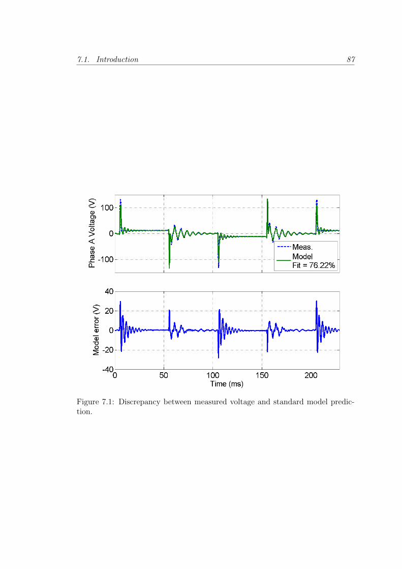
7.1. Introduction 87
Figure 7.1: Discrepancy between measured voltage and standard model predic-tion.
88Chapter 7. Hybrid Stepper Motors Electrical Model Extensions and Their
Application to Sensorless Estimation
7.2 Proposed new model extensions
In this section new model extensions are proposed which incorporate terms that
can account for the mismatch of Section 7.1.2. Specifically terms that could
explain the induced voltages current dependency are presented.
7.2.1 Position dependency
The literature on Hybrid Stepper Motors, in general, assumes that the phase
inductance angular position dependence is negligible, e.g. [1, 36]. Whilst the
effect may be less pronounced than in Variable Reluctance Stepper Motors, it,
nonetheless, exists in HSMs due to the variation of the gap distance, and thus
reluctance, between stator and rotor caused by their toothed profile. Furthermore
its significance may not always be negligible. In [34, 46] it is shown that there
is a dependence of the permeance on position, which produces a variation of the
inductance and the flux linkage.
If this is the case then we have that the flux linking the stator phase j is given
by:
ψpdj = Lj(θ)ij + ψPMj (θ) (7.6)
where phase j inductance Lj(θ) is now position-dependent.
By Faraday’s law, the induced voltage in a phase is then:
vpdj =dψpdjdt
=dLjdθ
ωij + Ljdijdt
+dψPMjdθ
ω. (7.7)
It can be seen from Eq. (7.7) that a position-dependent inductance indirectly
leads to a current dependent induced voltage term.
7.2.2 Current dependency
A further effect can occur in the form of current level dependence. The flux linking
the stator phase follows a magnetic circuit that contains the rotor permanent
magnet, iron teeth, the air gaps between the rotor and stator and the stator iron
cores.
As is well known in magnetic theory, a nonlinear relation exists between the
flux magnitude in iron and the current level producing it, via the permeability,
as seen in the B-H curve. Moreover, eventually saturation can occur at high flux
7.2. Proposed new model extensions 89
levels.
HSM can be more prone to saturation than other types of motor since they
typically have a large number of small teeth, which can lead to high flux densities,
see e.g. [40].
In [34, 46] the dependence of the permeance with current is also studied. It
can, therefore, be important to consider this phenomenon in an HSM model. This
means that in this case the flux linkage expression becomes current dependent:
ψcdj = Lj(ij)ij + ψPMj (θ, ij), (7.8)
where both phase j inductance Lj(ij) and the flux linkage produced by the per-
manent magnet ψPMj (θ, ij) are now current-dependent. The latter is still position
dependant since this dependence is considered in the standard model (7.2)-(7.5).
The current-dependency of the permanent magnet flux linkage can be ex-
plained by the fact that, for a certain operating point, the permanent magnet
can be considered as a constant source of magnetomotive force [57]. The flux,
and thus the linkage that it generates are, therefore, dependent on the overall
reluctance of the magnetic circuit at that operating point, which in itself is a
function of current, via the current dependent permeability term contained in
the reluctance.
By Faraday’s law, the induced voltage in a phase is:
vcdj =dψcdjdt
=dLjdij
dijdtij + Lj
dijdt
+∂ψPMj∂ij
dijdt
+∂ψPMj∂θ
ω. (7.9)
7.2.3 Position and Current dependency
When neither of the dependencies, on position and on current, are negligible,
a model combining them becomes necessary. The flux linkage combining both
dependencies has the following expression:
ψpcdj = Lj(θ, ij)ij + ψPMj (θ, ij). (7.10)
By Faraday’s law, the induced voltage is:
vpcdj =dψpcdj
dt=∂Lj∂ij
dijdtij +
∂Lj∂θ
ωij + Ljdijdt
+∂ψPMj∂ij
dijdt
+∂ψPMj∂θ
ω. (7.11)
90Chapter 7. Hybrid Stepper Motors Electrical Model Extensions and Their
Application to Sensorless Estimation
7.3 Determination of the model structure
The equations for the electrical model of the motor with the different dependencies
introduced has been presented. It is then necessary to find the models for each of
the new terms introduced, keeping in mind that the final goal is to use them in
a real-time embedded system. In this section the model structures are proposed
and experimentally validated. All the tests are performed on the same two phase
hybrid stepper motor as in section 7.1.2.
7.3.1 Position Dependency
Estimation of the Permanent Magnet Flux linkage as a function of the
position
The permanent magnet flux linkage position dependency is assessed by using a
speed controlled synchronous motor to drive the open-phase HSM at a constant
reference speed of 190 rpm, approximately 3.1 turns per second.
The speed has been chosen to allow 3 mechanical turns to be acquired over a
2 seconds duration. The Nyquist-Shannon Sampling Theorem is easily satisfied
when the data is acquired at a 25 kHz sampling rate, even assuming the first 10
harmonics to be significant. The motor open-phase voltages and angular position
are acquired.
Since the phases are open, zero current can flow in them, thus removing all
current dependent terms from the model (7.7), as shown in Eq. (7.12).
vpdj
∣∣∣ij=0
=dψPMjdθ
ω (7.12)
The permanent magnet flux linkages with the phases are considered to be
periodic as a function of position and to have a fundamental period equal to that
of the motor electrical period. Using this assumption, a general model for the
voltages induced by cutting of this flux linkage is thus:
vPMA =dψPMAdt
= −M∑
r=1
r pΨPMr ω sin(r pθ + φPM,r)
vPMB =dψPMBdt
=M∑
r=1
r pΨPMr ω cos(r pθ + φPM,r), (7.13)
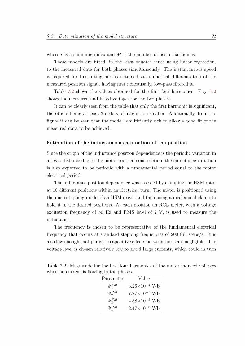
7.3. Determination of the model structure 91
where r is a summing index and M is the number of useful harmonics.
These models are fitted, in the least squares sense using linear regression,
to the measured data for both phases simultaneously. The instantaneous speed
is required for this fitting and is obtained via numerical differentiation of the
measured position signal, having first noncausally, low-pass filtered it.
Table 7.2 shows the values obtained for the first four harmonics. Fig. 7.2
shows the measured and fitted voltages for the two phases.
It can be clearly seen from the table that only the first harmonic is significant,
the others being at least 3 orders of magnitude smaller. Additionally, from the
figure it can be seen that the model is sufficiently rich to allow a good fit of the
measured data to be achieved.
Estimation of the inductance as a function of the position
Since the origin of the inductance position dependence is the periodic variation in
air gap distance due to the motor toothed construction, the inductance variation
is also expected to be periodic with a fundamental period equal to the motor
electrical period.
The inductance position dependence was assessed by clamping the HSM rotor
at 16 different positions within an electrical turn. The motor is positioned using
the microstepping mode of an HSM drive, and then using a mechanical clamp to
hold it in the desired positions. At each position an RCL meter, with a voltage
excitation frequency of 50 Hz and RMS level of 2 V, is used to measure the
inductance.
The frequency is chosen to be representative of the fundamental electrical
frequency that occurs at standard stepping frequencies of 200 full steps/s. It is
also low enough that parasitic capacitive effects between turns are negligible. The
voltage level is chosen relatively low to avoid large currents, which could in turn
Table 7.2: Magnitude for the first four harmonics of the motor induced voltageswhen no current is flowing in the phases.
Parameter Value
ΨPM1 3.26×10⁻² Wb
ΨPM2 7.27×10⁻⁵ Wb
ΨPM3 4.38×10⁻⁵ Wb
ΨPM4 2.47×10⁻⁶ Wb

92Chapter 7. Hybrid Stepper Motors Electrical Model Extensions and Their
Application to Sensorless Estimation
Figure 7.2: Measured (dashed) and fitted (solid) open phase voltages.
cause magnetic saturation.
The clamping of the rotor is necessary for two reasons. First, in order to
avoid movement due to the, albeit small, excitation voltage and second, to have
the capacity of stopping the motor at arbitrary positions, since once the current
is removed from the phases, the rotor tends to align with the stator in specific
angles due to the detent torque. Moreover, as can be seen from (7.7), with zero
movement, all induced voltage terms due to relative movement of the rotor are
zero, resulting in the model simplified to (7.14).
vpdj
∣∣∣ω=0
= Ljdijdt
(7.14)
Furthermore, since the meter excitation voltage is zero mean, and the system
can be considered linear, so the current is also zero mean, removing effects of
the current amplitude dependency. 16 different positions per electrical turn were
used in order to satisfy the Nyquist-Shannon Sampling Theorem, assuming that
the 8th harmonic would be negligible.
The results over 3 electrical turns are shown in Fig. 7.3.
As can be seen, the inductances are clearly position dependent. Moreover,
their dependences are 180 out of phase between the two motor phases and can,
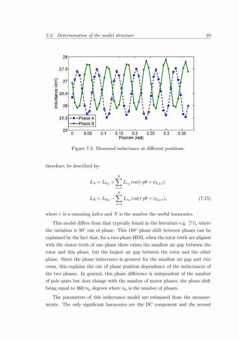
7.3. Determination of the model structure 93
Figure 7.3: Measured inductance at different positions.
therefore, be described by:
LA = L0A +N∑
r=1
LrA cos(r pθ + φLA,r)
LB = L0B −N∑
r=1
LrB cos(r pθ + φLB ,r), (7.15)
where r is a summing index and N is the number the useful harmonics.
This model differs from that typically found in the literature e.g. [71], where
the variation is 90 out of phase. This 180 phase shift between phases can be
explained by the fact that, for a two-phase HSM, when the rotor teeth are aligned
with the stator teeth of one phase there exists the smallest air gap between the
rotor and this phase, but the largest air gap between the rotor and the other
phase. Since the phase inductance is greatest for the smallest air gap and vice
versa, this explains the out of phase position dependency of the inductances of
the two phases. In general, this phase difference is independent of the number
of pole pairs but does change with the number of motor phases, the phase shift
being equal to 360/np degrees where np is the number of phases.
The parameters of this inductance model are estimated from the measure-
ments. The only significant harmonics are the DC component and the second
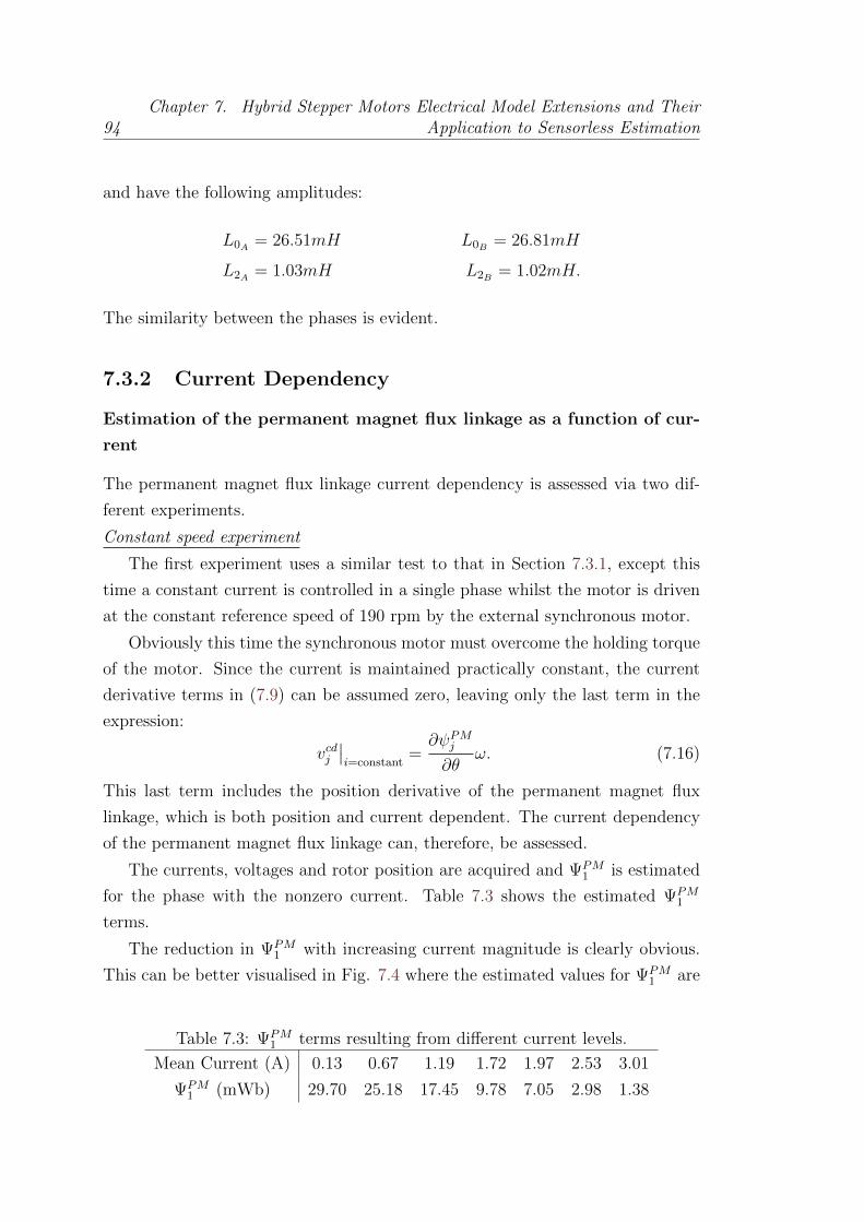
94Chapter 7. Hybrid Stepper Motors Electrical Model Extensions and Their
Application to Sensorless Estimation
and have the following amplitudes:
L0A = 26.51mH L0B = 26.81mH
L2A = 1.03mH L2B = 1.02mH.
The similarity between the phases is evident.
7.3.2 Current Dependency
Estimation of the permanent magnet flux linkage as a function of cur-
rent
The permanent magnet flux linkage current dependency is assessed via two dif-
ferent experiments.
Constant speed experiment
The first experiment uses a similar test to that in Section 7.3.1, except this
time a constant current is controlled in a single phase whilst the motor is driven
at the constant reference speed of 190 rpm by the external synchronous motor.
Obviously this time the synchronous motor must overcome the holding torque
of the motor. Since the current is maintained practically constant, the current
derivative terms in (7.9) can be assumed zero, leaving only the last term in the
expression:
vcdj∣∣i=constant
=∂ψPMj∂θ
ω. (7.16)
This last term includes the position derivative of the permanent magnet flux
linkage, which is both position and current dependent. The current dependency
of the permanent magnet flux linkage can, therefore, be assessed.
The currents, voltages and rotor position are acquired and ΨPM1 is estimated
for the phase with the nonzero current. Table 7.3 shows the estimated ΨPM1
terms.
The reduction in ΨPM1 with increasing current magnitude is clearly obvious.
This can be better visualised in Fig. 7.4 where the estimated values for ΨPM1 are
Table 7.3: ΨPM1 terms resulting from different current levels.
Mean Current (A) 0.13 0.67 1.19 1.72 1.97 2.53 3.01
ΨPM1 (mWb) 29.70 25.18 17.45 9.78 7.05 2.98 1.38

7.3. Determination of the model structure 95
plotted against mean current.
Two models have been fitted to the data, an ‘exponential’ model with the
form:
ΨPM1 (i) = aψe
−bψi2 + cψ (7.17)
and a ‘linear’ model with the form:
ΨPM1 (i) = dψ|i|+ fψ. (7.18)
As can be seen from the figure, where the Root Mean Squared Error (RMSE) is
displayed for each model, the exponential model achieves a better fit. Additionally
it is Lipschitz continuous, which is an important property given the derivative
terms found in (7.9) and (7.11).
The estimated parameters for the model are:
aψ = 29.36 mWb
bψ = 0.39 A−2
cψ = 0.52 mWb
Holding torque experiment
The second experiment involved measuring the motor holding torque at differ-
ent current levels. Assuming that only the first position harmonic of the motor
induced voltage is significant, we can obtain the expression for the torque by
following the coenergy approach as presented in [26].
Using the equation (7.17) to express the current dependency of the flux, and
leaving the inductance L with explicit dependency on the current, the flux linkage
for phase A is:
ψcdA = ψLA + ψPMA = L(iA)iA + ΨPMA (iA) cos(pθ).
(7.19)

96Chapter 7. Hybrid Stepper Motors Electrical Model Extensions and Their
Application to Sensorless Estimation
Figure 7.4: Estimated and fitted ΨPM1 .
The coenergy is:
W ′cdA =
∫ iA
0
(ψcdA )di =
∫ iA
0
(L(i)i+ ΨPMA (i) cos(pθ))di
=
∫ iA
0
L(i)idi+
∫ iA
0
(aψe−bψi2 + cψ) cos(pθ)di
= fL(iA) +
(aψ2
√π
bψerf(
√bψiA) + cψiA
)cos(pθ), (7.20)
where erf(·) is the error function 1 and fL(i) is an expression dependant only on
the current.
For the purpose of this section, which is to obtain an expression for the torque,
the explicit expression of the inductance L as a function of the current is not
necessary since, to obtain the torque expression, the equation (7.20) is derived
with respect to position θ, and so the derivative of the term fL(i) is 0. The
current dependence of the inductance L is studied in the following section.
The torque produced by phase A is obtained deriving the coenergy with re-
spect to the position θ:
τ cdA =∂W ′cd
A
∂θ=
(aψ2
√π
bψerf(
√bψiA) + cψiA
)(−p) sin(pθ). (7.21)
1 Error function: erf(x) = 2π
∫ x0e−t
2
dt

7.3. Determination of the model structure 97
Following the equivalent procedure for phase B, the torque obtained is:
τ cdB =∂W ′cd
B
∂θ=
(aψ2
√π
bψerf(
√bψiB) + cψiB
)p cos(pθ). (7.22)
An experiment was performed whereby a range of constant current values were
controlled in the phases in two different modes, One phase on and Two phases
on.
For each I value, a slowly increasing external torque was applied to the HSM
shaft using an external synchronous motor up to a pre-set limit. The current in
each phase, position and applied torque were acquired using dedicated sensors.
The pre-set limit of the applied torque was adjusted according to a bisection
algorithm in order to converge to the maximum applied torque that did not cause
step loss, as diagnosed by the position measurement. For each pre-set torque level
1000 torque measurements were acquired and averaged. The average torque that
was measured during the penultimate run before steps were lost was taken as the
holding torque. The mean current in the phases for this run was also noted.
The detent torque, τdm(θ), has been estimated separately as having a mag-
nitude of approximately 0.06 Nm. Similarly the static friction torque, Tsf , has
been found to have an amplitude of approximately 0.09 Nm. These values are
relatively negligible compared to standard electromagnetic torques so will be ne-
glected henceforth.
Using the expressions for the produced torque (7.21)-(7.22), the holding torque
can be written as:
τ cdh (iA, iB) = maxθ
∣∣τ cdA + τ cdB∣∣ . (7.23)
To obtain the maximum torque in equation (7.23), its extreme values have to be
found by deriving it with respect to position θ and equating to 0.
In the One phase on case, phase A being the energised one, the angle giving
the maximum torque is:
θmax =π/2± kπ
pwith k = 0, 1, 2, . . . .
It can be seen in (7.21) that these are the values making the |sin(pθ)| term
equal to 1. In case that phase B were the energised one, the θ values making the
98Chapter 7. Hybrid Stepper Motors Electrical Model Extensions and Their
Application to Sensorless Estimation
torque maximum would be:
θmax = ±kπ/p with k = 0, 1, 2, . . . ,
for which |cos(pθ)| is equal to 1.
The resulting holding torque is, for the phase A case:
τ cdh (I, 0) = p
(aψ2
√π
bψerf(
√bψI) + cψI
). (7.24)
Note that the result is the same energising phase B.
For the Two phases on case and the same current, the maximum torque is for
the angles:
θmax =−π/4± kπ
pwith k = 0, 1, 2, . . . ,
and the holding torque:
τ cdh (I, I) =√
2p
(aψ2
√π
bψerf(
√bψI) + cψI
). (7.25)
Fig. 7.5 shows the holding torques measured for different values of current
IRMS. It should be noted that for full and half step modes, the current applied
to the motor phase is I =√
2IRMS in the step that corresponds to One phase on
and I = IRMS when the step corresponds to Two phases on.
It can clearly be seen how the holding torque is a nonlinear function of the
current due to the nonlinear dependence of ΨPM1 on the current. Additionally a
clear difference in the saturation between the ‘One phase on’ case and the ‘Two
phases on’ case can be observed. This difference can be explained by the fact
that with One phase on, for the same IRMS value, more current is flowing in the
phase and therefore it is closer to saturation than for the Two phases on case.
A fit is performed to the data for One phase on, using Equation (7.24) and the
exponential model (7.17) for ΨPM1 (I). The resulting model is then used with the
data for both One phase on and Two phases on and its holding torque predictions
for the two cases are also shown in Fig. 7.5. The estimated parameters for the
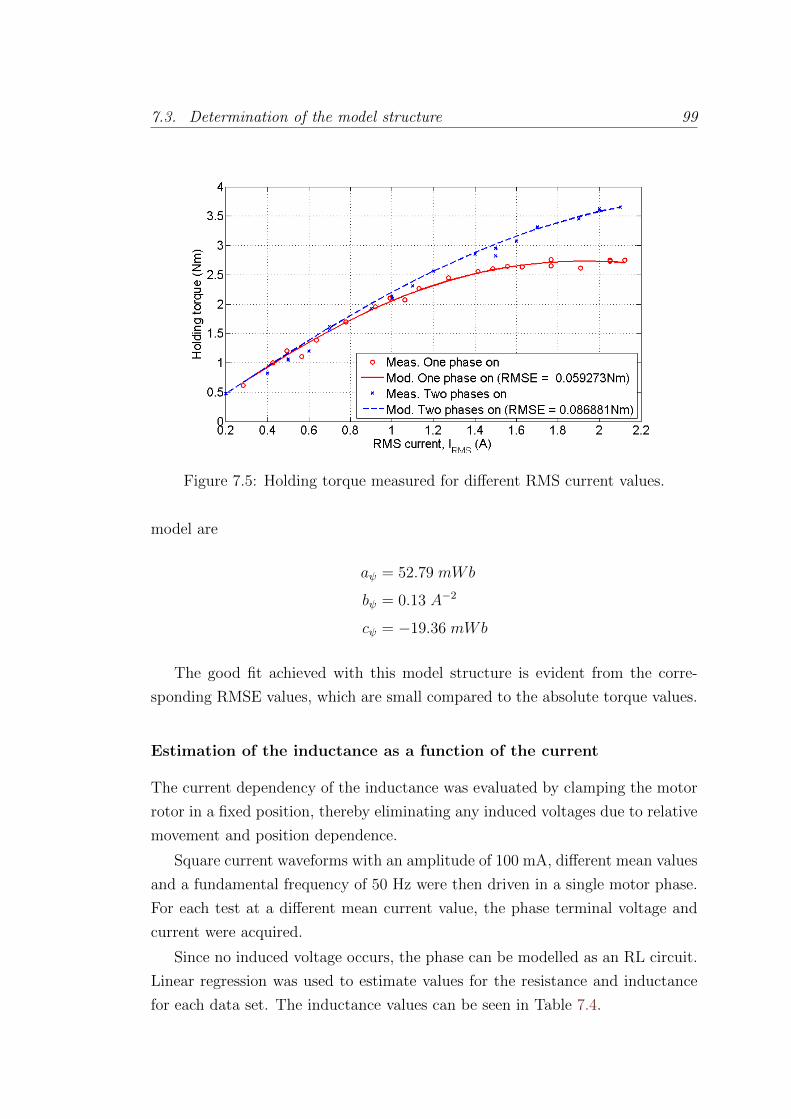
7.3. Determination of the model structure 99
Figure 7.5: Holding torque measured for different RMS current values.
model are
aψ = 52.79 mWb
bψ = 0.13 A−2
cψ = −19.36 mWb
The good fit achieved with this model structure is evident from the corre-
sponding RMSE values, which are small compared to the absolute torque values.
Estimation of the inductance as a function of the current
The current dependency of the inductance was evaluated by clamping the motor
rotor in a fixed position, thereby eliminating any induced voltages due to relative
movement and position dependence.
Square current waveforms with an amplitude of 100 mA, different mean values
and a fundamental frequency of 50 Hz were then driven in a single motor phase.
For each test at a different mean current value, the phase terminal voltage and
current were acquired.
Since no induced voltage occurs, the phase can be modelled as an RL circuit.
Linear regression was used to estimate values for the resistance and inductance
for each data set. The inductance values can be seen in Table 7.4.
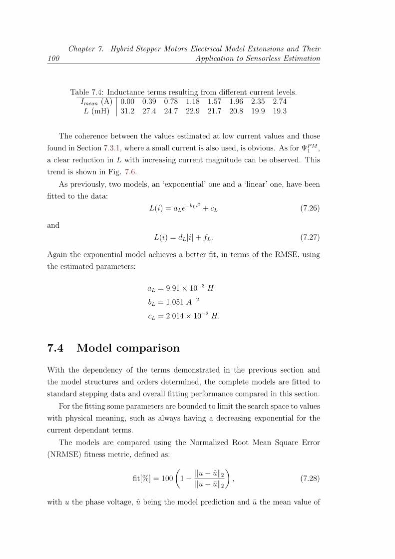
100Chapter 7. Hybrid Stepper Motors Electrical Model Extensions and Their
Application to Sensorless Estimation
Table 7.4: Inductance terms resulting from different current levels.Imean (A) 0.00 0.39 0.78 1.18 1.57 1.96 2.35 2.74L (mH) 31.2 27.4 24.7 22.9 21.7 20.8 19.9 19.3
The coherence between the values estimated at low current values and those
found in Section 7.3.1, where a small current is also used, is obvious. As for ΨPM1 ,
a clear reduction in L with increasing current magnitude can be observed. This
trend is shown in Fig. 7.6.
As previously, two models, an ‘exponential’ one and a ‘linear’ one, have been
fitted to the data:
L(i) = aLe−bLi2 + cL (7.26)
and
L(i) = dL|i|+ fL. (7.27)
Again the exponential model achieves a better fit, in terms of the RMSE, using
the estimated parameters:
aL = 9.91× 10⁻³ H
bL = 1.051 A−2
cL = 2.014× 10⁻² H.
7.4 Model comparison
With the dependency of the terms demonstrated in the previous section and
the model structures and orders determined, the complete models are fitted to
standard stepping data and overall fitting performance compared in this section.
For the fitting some parameters are bounded to limit the search space to values
with physical meaning, such as always having a decreasing exponential for the
current dependant terms.
The models are compared using the Normalized Root Mean Square Error
(NRMSE) fitness metric, defined as:
fit[%] = 100
(1− ‖u− u‖2
‖u− u‖2
), (7.28)
with u the phase voltage, u being the model prediction and u the mean value of
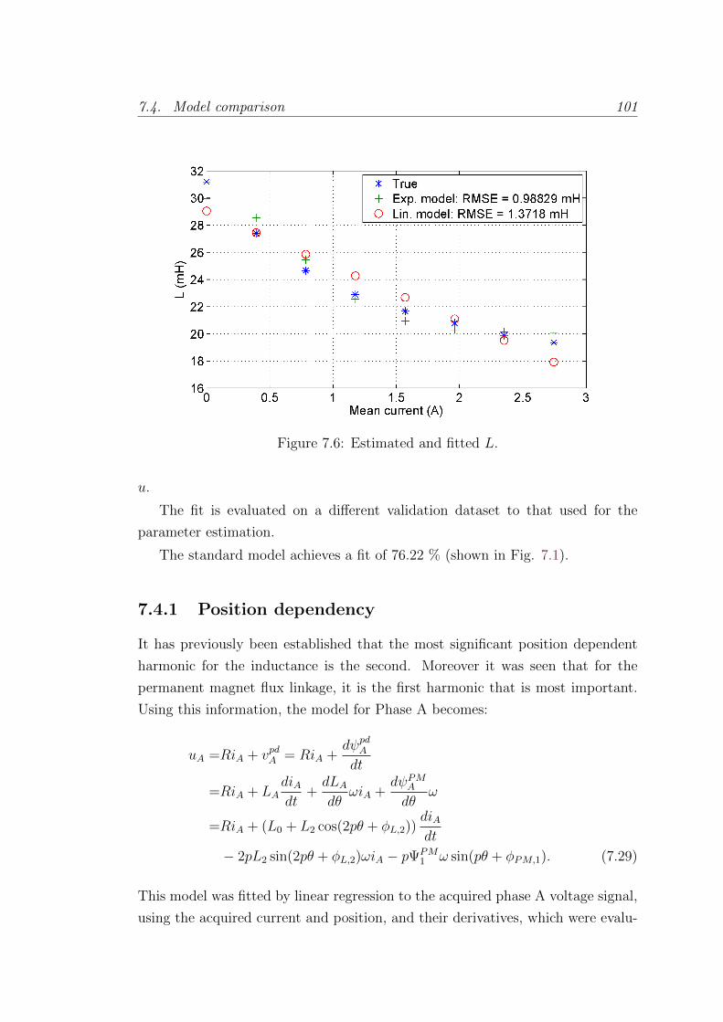
7.4. Model comparison 101
Figure 7.6: Estimated and fitted L.
u.
The fit is evaluated on a different validation dataset to that used for the
parameter estimation.
The standard model achieves a fit of 76.22 % (shown in Fig. 7.1).
7.4.1 Position dependency
It has previously been established that the most significant position dependent
harmonic for the inductance is the second. Moreover it was seen that for the
permanent magnet flux linkage, it is the first harmonic that is most important.
Using this information, the model for Phase A becomes:
uA =RiA + vpdA = RiA +dψpdAdt
=RiA + LAdiAdt
+dLAdθ
ωiA +dψPMAdθ
ω
=RiA + (L0 + L2 cos(2pθ + φL,2))diAdt
− 2pL2 sin(2pθ + φL,2)ωiA − pΨPM1 ω sin(pθ + φPM,1). (7.29)
This model was fitted by linear regression to the acquired phase A voltage signal,
using the acquired current and position, and their derivatives, which were evalu-
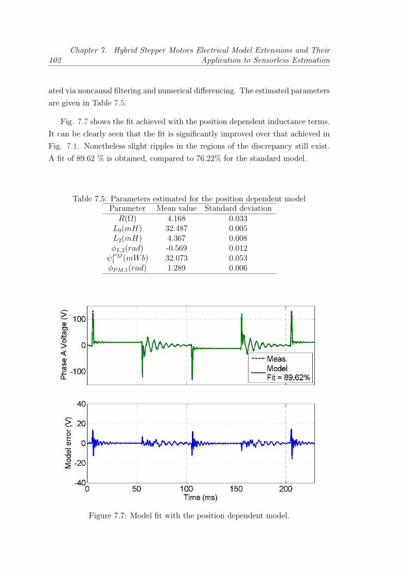
102Chapter 7. Hybrid Stepper Motors Electrical Model Extensions and Their
Application to Sensorless Estimation
ated via noncausal filtering and numerical differencing. The estimated parameters
are given in Table 7.5.
Fig. 7.7 shows the fit achieved with the position dependent inductance terms.
It can be clearly seen that the fit is significantly improved over that achieved in
Fig. 7.1. Nonetheless slight ripples in the regions of the discrepancy still exist.
A fit of 89.62 % is obtained, compared to 76.22% for the standard model.
Table 7.5: Parameters estimated for the position dependent modelParameter Mean value Standard deviationR(Ω) 4.168 0.033
L0(mH) 32.487 0.005L2(mH) 4.367 0.008φL,2(rad) -0.569 0.012ψPM1 (mWb) 32.073 0.053φPM,1(rad) 1.289 0.006
Figure 7.7: Model fit with the position dependent model.

7.4. Model comparison 103
7.4.2 Current dependency
The use of the current dependent terms in the model is next considered. As seen
in the previous section, an exponential current dependency gives a good fit for
both the inductance and permanent magnet flux linkage terms. The complete
model using these terms is:
uA =RiA + vcdA = RiA +dψcdAdt
=RiA +dLAdiA
diAdtiA + LA
diAdt
+∂ψPMA∂iA
diAdt
+∂ψPMA∂θ
ω
=RiA − 2aLbLi2Ae−bLi2A
diAdt
+ (aLe−bLi2A + cL)
diAdt
− 2aψbψiAe−bψi2A cos(pθ + φPM,1)
diAdt− p(aψe−bψi
2A + cψ)ω sin(pθ + φPM,1).
(7.30)
As can be seen this model is nonlinearly dependent on its parameters. It is,
therefore, not possible to estimate its parameters using linear regression. The
parameters are thus estimated using a trust region reflective nonlinear optimi-
sation routine to minimise a quadratic cost function between the model voltage
prediction and the measured voltage. This routine was implemented using the
lsqnonlin function in Matlab. It is initialised using the parameters found in Sec-
tion 7.3.2 for the exponential function parameters and the values found via the
linear regression for the standard model for R and φPM,1. The parameters found
after the nonlinear optimisation can be seen in Table 7.6.
Fig. 7.8 shows the fit achieved with the current dependent model. The fit is
91.28%, compared to 76.22% for the standard model and 89.62 % for the position
Table 7.6: Parameters estimated for the current dependent modelParameter Mean value Standard deviationR(Ω) 4.155 0.033
aL(mH) 1.628 0.053bL(A−2) 28.923 0.759cL(mH) 40.375 0.016aψ(mWb) 42.211 0.238bψ(A−2) 0.200 0.003cψ(mWb) -10.538 0.243φPM,1(rad) 1.380 0.006
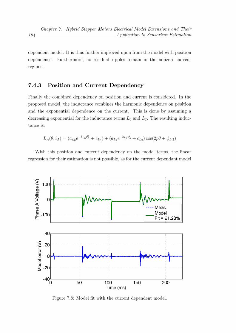
104Chapter 7. Hybrid Stepper Motors Electrical Model Extensions and Their
Application to Sensorless Estimation
dependent model. It is thus further improved upon from the model with position
dependence. Furthermore, no residual ripples remain in the nonzero current
regions.
7.4.3 Position and Current Dependency
Finally the combined dependency on position and current is considered. In the
proposed model, the inductance combines the harmonic dependence on position
and the exponential dependence on the current. This is done by assuming a
decreasing exponential for the inductance terms L0 and L2. The resulting induc-
tance is:
LA(θ, iA) = (aL0e−bL0
i2A + cL0) + (aL2e−bL2
i2A + cL2) cos(2pθ + φL,2)
With this position and current dependency on the model terms, the linear
regression for their estimation is not possible, as for the current dependant model
Figure 7.8: Model fit with the current dependent model.
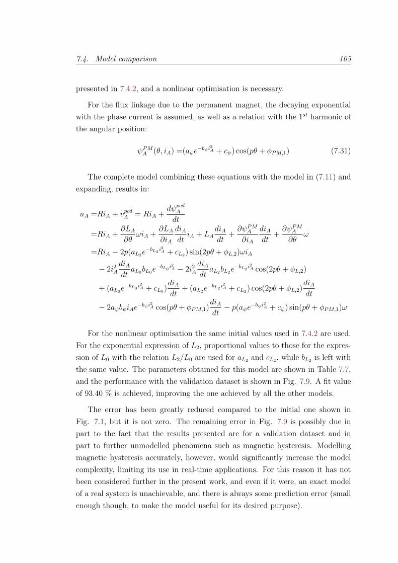
7.4. Model comparison 105
presented in 7.4.2, and a nonlinear optimisation is necessary.
For the flux linkage due to the permanent magnet, the decaying exponential
with the phase current is assumed, as well as a relation with the 1st harmonic of
the angular position:
ψPMA (θ, iA) =(aψe−bψi2A + cψ) cos(pθ + φPM,1) (7.31)
The complete model combining these equations with the model in (7.11) and
expanding, results in:
uA =RiA + vpcdA = RiA +dψpcdA
dt
=RiA +∂LA∂θ
ωiA +∂LA∂iA
diAdtiA + LA
diAdt
+∂ψPMA∂iA
diAdt
+∂ψPMA∂θ
ω
=RiA − 2p(aL2e−bL2
i2A + cL2) sin(2pθ + φL,2)ωiA
− 2i2AdiAdtaL0bL0e
−bL0i2A − 2i2A
diAdtaL2bL2e
−bL2i2A cos(2pθ + φL,2)
+ (aL0e−bL0
i2A + cL0)diAdt
+ (aL2e−bL2
i2A + cL2) cos(2pθ + φL,2)diAdt
− 2aψbψiAe−bψi2A cos(pθ + φPM,1)
diAdt− p(aψe−bψi
2A + cψ) sin(pθ + φPM,1)ω
For the nonlinear optimisation the same initial values used in 7.4.2 are used.
For the exponential expression of L2, proportional values to those for the expres-
sion of L0 with the relation L2/L0 are used for aL2 and cL2 , while bL2 is left with
the same value. The parameters obtained for this model are shown in Table 7.7,
and the performance with the validation dataset is shown in Fig. 7.9. A fit value
of 93.40 % is achieved, improving the one achieved by all the other models.
The error has been greatly reduced compared to the initial one shown in
Fig. 7.1, but it is not zero. The remaining error in Fig. 7.9 is possibly due in
part to the fact that the results presented are for a validation dataset and in
part to further unmodelled phenomena such as magnetic hysteresis. Modelling
magnetic hysteresis accurately, however, would significantly increase the model
complexity, limiting its use in real-time applications. For this reason it has not
been considered further in the present work, and even if it were, an exact model
of a real system is unachievable, and there is always some prediction error (small
enough though, to make the model useful for its desired purpose).
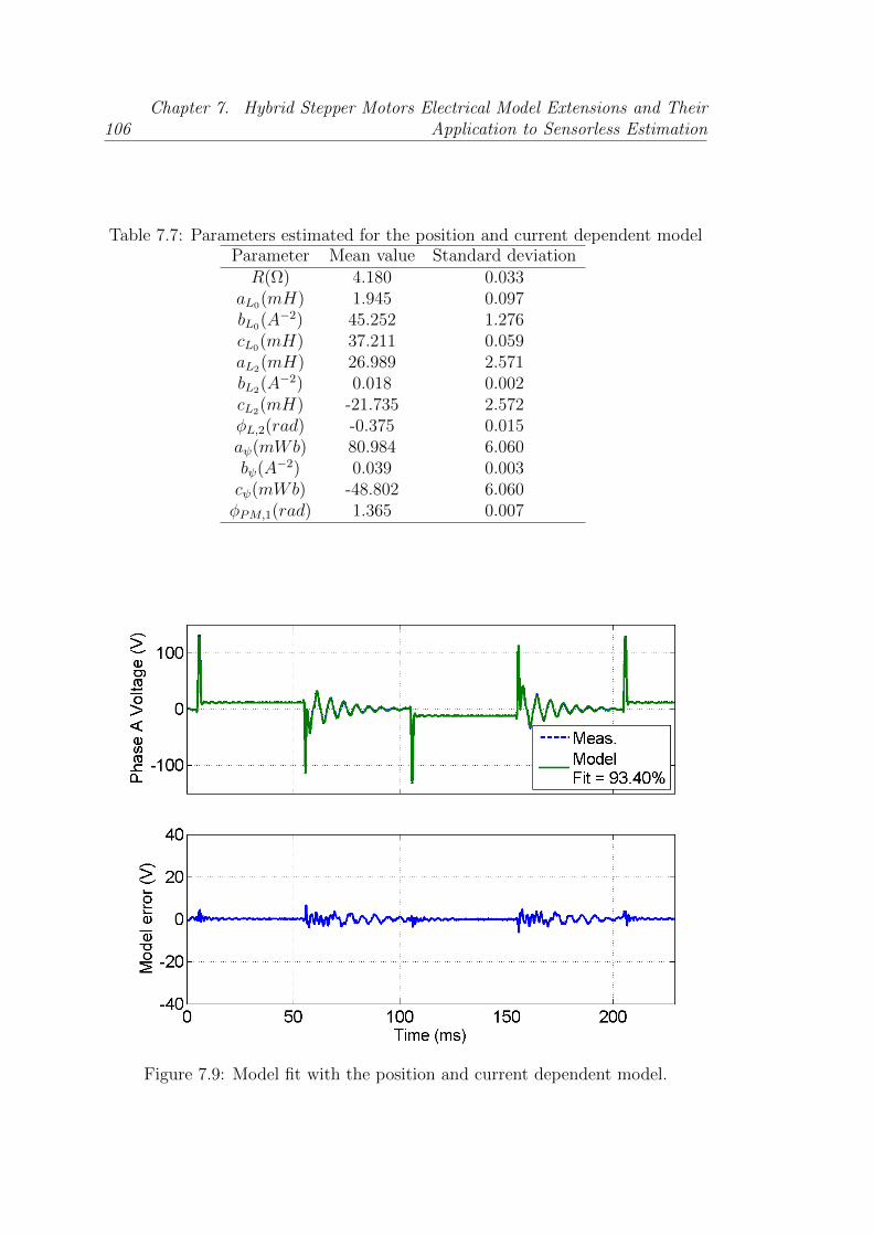
106Chapter 7. Hybrid Stepper Motors Electrical Model Extensions and Their
Application to Sensorless Estimation
Table 7.7: Parameters estimated for the position and current dependent modelParameter Mean value Standard deviationR(Ω) 4.180 0.033
aL0(mH) 1.945 0.097bL0(A−2) 45.252 1.276cL0(mH) 37.211 0.059aL2(mH) 26.989 2.571bL2(A−2) 0.018 0.002cL2(mH) -21.735 2.572φL,2(rad) -0.375 0.015aψ(mWb) 80.984 6.060bψ(A−2) 0.039 0.003cψ(mWb) -48.802 6.060φPM,1(rad) 1.365 0.007
Figure 7.9: Model fit with the position and current dependent model.
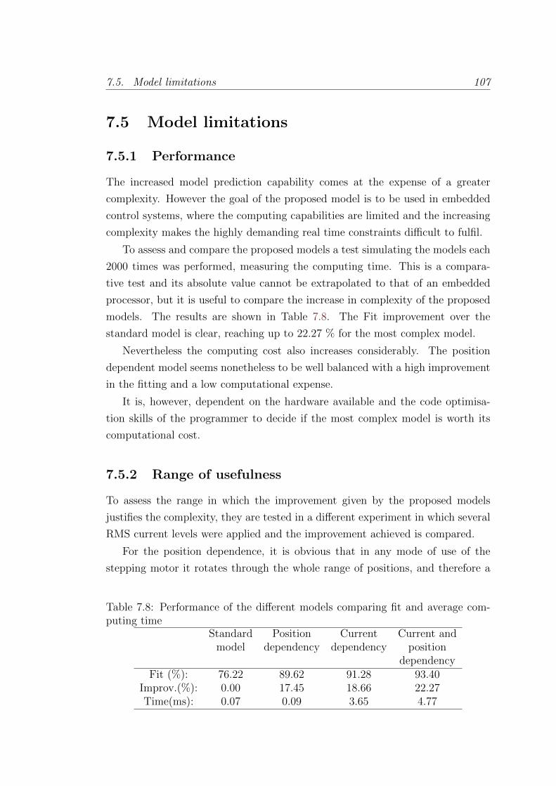
7.5. Model limitations 107
7.5 Model limitations
7.5.1 Performance
The increased model prediction capability comes at the expense of a greater
complexity. However the goal of the proposed model is to be used in embedded
control systems, where the computing capabilities are limited and the increasing
complexity makes the highly demanding real time constraints difficult to fulfil.
To assess and compare the proposed models a test simulating the models each
2000 times was performed, measuring the computing time. This is a compara-
tive test and its absolute value cannot be extrapolated to that of an embedded
processor, but it is useful to compare the increase in complexity of the proposed
models. The results are shown in Table 7.8. The Fit improvement over the
standard model is clear, reaching up to 22.27 % for the most complex model.
Nevertheless the computing cost also increases considerably. The position
dependent model seems nonetheless to be well balanced with a high improvement
in the fitting and a low computational expense.
It is, however, dependent on the hardware available and the code optimisa-
tion skills of the programmer to decide if the most complex model is worth its
computational cost.
7.5.2 Range of usefulness
To assess the range in which the improvement given by the proposed models
justifies the complexity, they are tested in a different experiment in which several
RMS current levels were applied and the improvement achieved is compared.
For the position dependence, it is obvious that in any mode of use of the
stepping motor it rotates through the whole range of positions, and therefore a
Table 7.8: Performance of the different models comparing fit and average com-puting time
Standard Position Current Current andmodel dependency dependency position
dependencyFit (%): 76.22 89.62 91.28 93.40
Improv.(%): 0.00 17.45 18.66 22.27Time(ms): 0.07 0.09 3.65 4.77
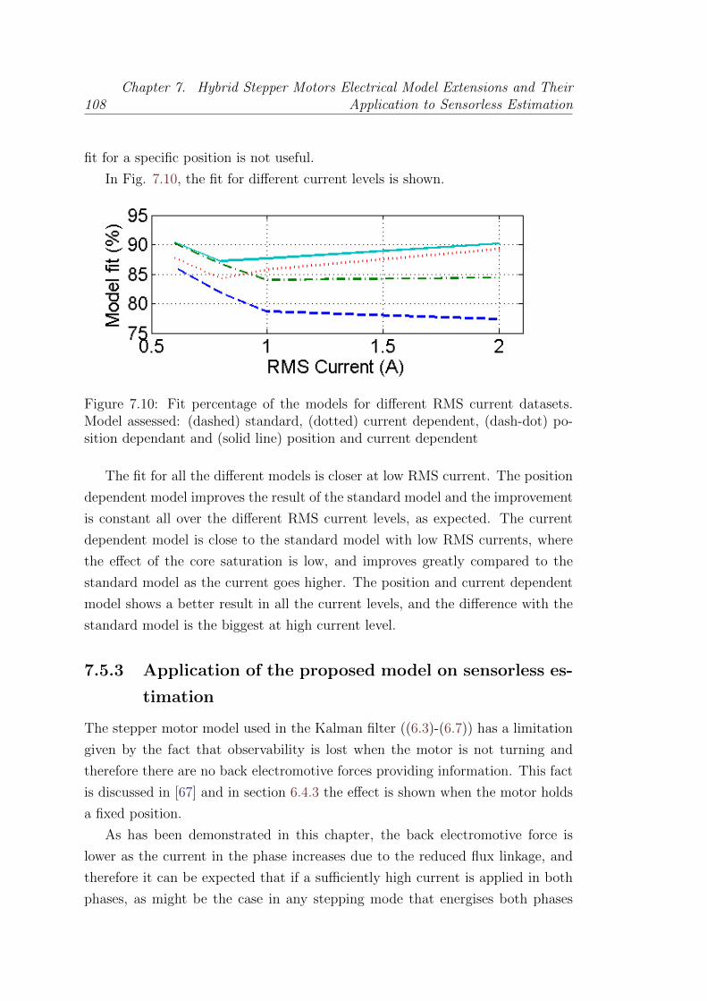
108Chapter 7. Hybrid Stepper Motors Electrical Model Extensions and Their
Application to Sensorless Estimation
fit for a specific position is not useful.
In Fig. 7.10, the fit for different current levels is shown.
Figure 7.10: Fit percentage of the models for different RMS current datasets.Model assessed: (dashed) standard, (dotted) current dependent, (dash-dot) po-sition dependant and (solid line) position and current dependent
The fit for all the different models is closer at low RMS current. The position
dependent model improves the result of the standard model and the improvement
is constant all over the different RMS current levels, as expected. The current
dependent model is close to the standard model with low RMS currents, where
the effect of the core saturation is low, and improves greatly compared to the
standard model as the current goes higher. The position and current dependent
model shows a better result in all the current levels, and the difference with the
standard model is the biggest at high current level.
7.5.3 Application of the proposed model on sensorless es-
timation
The stepper motor model used in the Kalman filter ((6.3)-(6.7)) has a limitation
given by the fact that observability is lost when the motor is not turning and
therefore there are no back electromotive forces providing information. This fact
is discussed in [67] and in section 6.4.3 the effect is shown when the motor holds
a fixed position.
As has been demonstrated in this chapter, the back electromotive force is
lower as the current in the phase increases due to the reduced flux linkage, and
therefore it can be expected that if a sufficiently high current is applied in both
phases, as might be the case in any stepping mode that energises both phases

7.6. Extended Kalman Filter: Theory and Experimental Results 109
at the same time, the observability would be reduced and even lost. It would
therefore be important to dimension the motor such that significant saturation
does not occur at nominal currents. An obvious solution useful for any any motor
would be to use full-step mode with one phase on, since in this way there is always
a motor phase with no current.
7.6 Extended Kalman Filter: Theory and Ex-
perimental Results
In this section, an Extended Kalman Filter, based on the position and current
dependent model defined in the previous section, is derived. Its estimation and
filtering performances in real time HSM control are also discussed and experi-
mentally evaluated.
7.6.1 State-space model derivation theory
In order to apply the EKF, as seen in chapters 5 and 6, a stepping motor model
expressed in state-space form should be used.
The formulation is taken as general as possible, so that its structure is valid
for all the models presented in this chapter. In the Appendix A, the symbolic
expressions are explicitly reported for reader’s convenience, focusing on the most
complete proposed HSM model with both position and current dependence.
Exploiting the voltage balance equations for each motor phase and the me-
chanical balance equation for a rigid body, the following system representing the
HSM can be derived:
x1 = NumA
DenA+ uA
DenA
x2 = NumB
DenB+ uB
DenB
x3 = τA+τBJ− B
Jx3 − Tdm
Jsin(2px4)− x5
J
x4 = x3
x5 = 0,
(7.32)
where τA and τB are the two phase electromagnetic torques, and the state x, the
input u and the output y vectors are the same as described in equations (6.4),
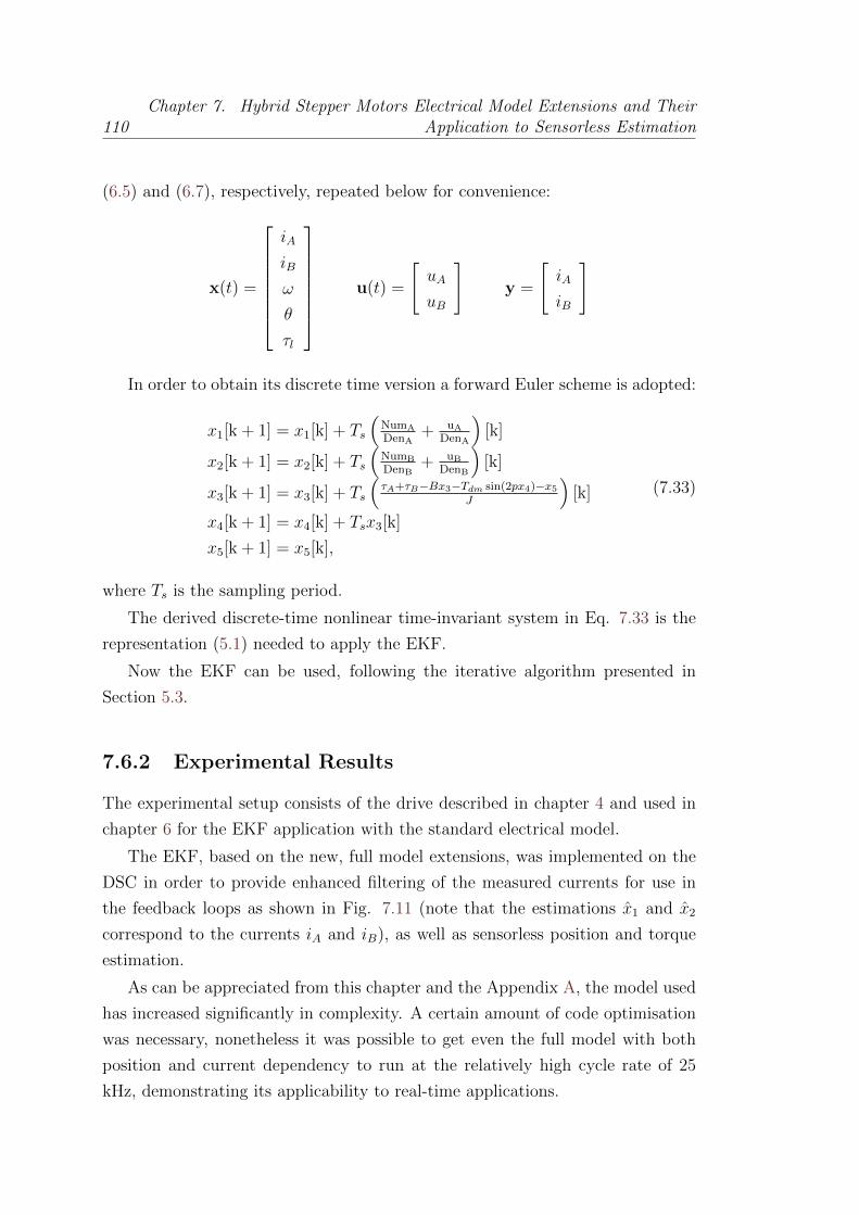
110Chapter 7. Hybrid Stepper Motors Electrical Model Extensions and Their
Application to Sensorless Estimation
(6.5) and (6.7), respectively, repeated below for convenience:
x(t) =
iA
iB
ω
θ
τl
u(t) =
[uA
uB
]y =
[iA
iB
]
In order to obtain its discrete time version a forward Euler scheme is adopted:
x1[k + 1] = x1[k] + Ts
(NumA
DenA+ uA
DenA
)[k]
x2[k + 1] = x2[k] + Ts
(NumB
DenB+ uB
DenB
)[k]
x3[k + 1] = x3[k] + Ts
(τA+τB−Bx3−Tdm sin(2px4)−x5
J
)[k]
x4[k + 1] = x4[k] + Tsx3[k]
x5[k + 1] = x5[k],
(7.33)
where Ts is the sampling period.
The derived discrete-time nonlinear time-invariant system in Eq. 7.33 is the
representation (5.1) needed to apply the EKF.
Now the EKF can be used, following the iterative algorithm presented in
Section 5.3.
7.6.2 Experimental Results
The experimental setup consists of the drive described in chapter 4 and used in
chapter 6 for the EKF application with the standard electrical model.
The EKF, based on the new, full model extensions, was implemented on the
DSC in order to provide enhanced filtering of the measured currents for use in
the feedback loops as shown in Fig. 7.11 (note that the estimations x1 and x2
correspond to the currents iA and iB), as well as sensorless position and torque
estimation.
As can be appreciated from this chapter and the Appendix A, the model used
has increased significantly in complexity. A certain amount of code optimisation
was necessary, nonetheless it was possible to get even the full model with both
position and current dependency to run at the relatively high cycle rate of 25
kHz, demonstrating its applicability to real-time applications.
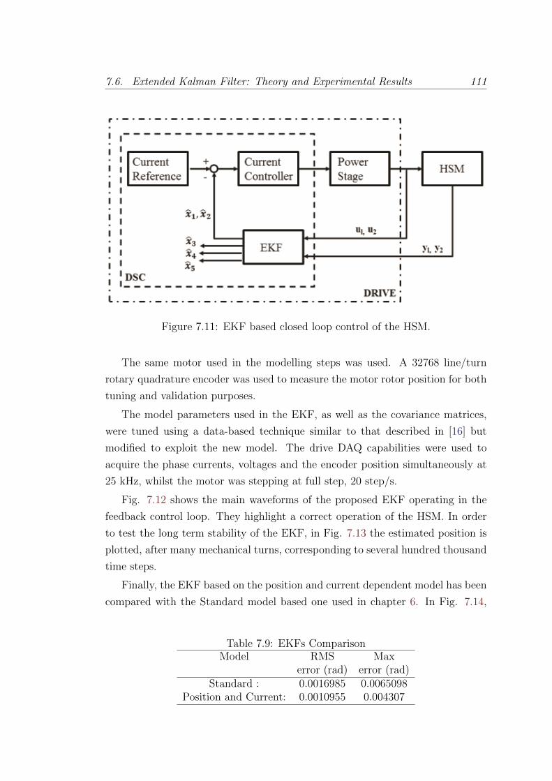
7.6. Extended Kalman Filter: Theory and Experimental Results 111
Figure 7.11: EKF based closed loop control of the HSM.
The same motor used in the modelling steps was used. A 32768 line/turn
rotary quadrature encoder was used to measure the motor rotor position for both
tuning and validation purposes.
The model parameters used in the EKF, as well as the covariance matrices,
were tuned using a data-based technique similar to that described in [16] but
modified to exploit the new model. The drive DAQ capabilities were used to
acquire the phase currents, voltages and the encoder position simultaneously at
25 kHz, whilst the motor was stepping at full step, 20 step/s.
Fig. 7.12 shows the main waveforms of the proposed EKF operating in the
feedback control loop. They highlight a correct operation of the HSM. In order
to test the long term stability of the EKF, in Fig. 7.13 the estimated position is
plotted, after many mechanical turns, corresponding to several hundred thousand
time steps.
Finally, the EKF based on the position and current dependent model has been
compared with the Standard model based one used in chapter 6. In Fig. 7.14,
Table 7.9: EKFs ComparisonModel RMS Max
error (rad) error (rad)Standard : 0.0016985 0.0065098
Position and Current: 0.0010955 0.004307

112Chapter 7. Hybrid Stepper Motors Electrical Model Extensions and Their
Application to Sensorless Estimation
Figure 7.12: Drive signals during closed loop operation.
the comparison of the position estimations is shown. The benefit of adopting
the proposed extended electrical model in the EKF is clear also for estimating
quantities that are not directly employed in the feedback line. In Table 7.9 the
RMS and max position estimation errors, for the two different approaches, are
computed.
7.7 Conclusions
New extensions of the standard electrical model of a hybrid stepper motor used for
control and observation purposes in modern, sophisticated drives are developed
and compared in this chapter.
It has been seen that inclusion of position and current dependent inductance
and permanent magnet flux linkage terms achieves a better fit to experimental
data, particularly for large current amplitudes.
However there is a tradeoff between the model fit improvement and the in-
crease in complexity, and it depends on the application which model is better to
use, or which one can be afforded.
Moreover, an Extended Kalman Filter based on the position and current de-
pendent HSM model has been formulated and implemented in a real time closed
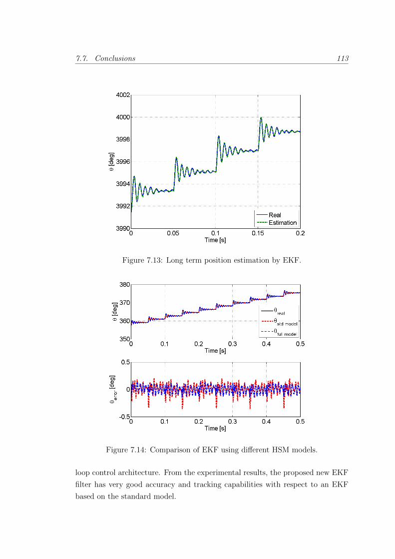
7.7. Conclusions 113
Figure 7.13: Long term position estimation by EKF.
Figure 7.14: Comparison of EKF using different HSM models.
loop control architecture. From the experimental results, the proposed new EKF
filter has very good accuracy and tracking capabilities with respect to an EKF
based on the standard model.

Part III
Field Oriented Control for
Stepper Motors

Chapter 8
Background on Field Oriented
Control
8.1 Introduction
As we saw in section 3.3, stepper motors are typically used in open loop in
positioning systems. We saw an example similar to the one presented in Fig.
8.1, where an acquisition of the rotor position and speed are shown. The large
overshoot of over 50 % can be easily appreciated, followed by several oscillations.
Looking at the speed, the rotor reaches again large values compared to the average
speed, which in this case with 40 steps per second is 1.25 rad/sec, whereas the
peak values reach 25 and -20 rad/sec.
In the LHC collimators, this jittery movement is tough for the mechanics. The
worm screw connected to the motor to move the collimator jaw linearly wears
and after a few years of use can need to be replaced, an expensive intervention.
It is therefore desirable to attempt to extend its lifespan. This could be achieved
with a smoother motion profile applied with the motor. To attain such a profile,
closed-loop position control is proposed using Field Oriented Control (FOC).
However, in chapter 3 it was claimed that relying on position sensors, as
needed for FOC, for critical operation, as is the case of the collimation system,
is preferably avoided in the LHC collimators, since it would reduce the reliability
of the whole system. A sensor failure could lead to the malfunctioning of the
collimator, and thus to the beam dump and stop of the machine. The cost of
such an event, plus the required maintenance of the collimator, is not affordable.
Sensorless control as presented in chapters 5 to 7 is an attractive option, but
115
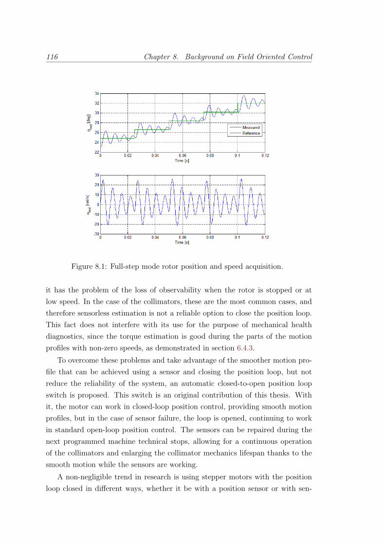
116 Chapter 8. Background on Field Oriented Control
Figure 8.1: Full-step mode rotor position and speed acquisition.
it has the problem of the loss of observability when the rotor is stopped or at
low speed. In the case of the collimators, these are the most common cases, and
therefore sensorless estimation is not a reliable option to close the position loop.
This fact does not interfere with its use for the purpose of mechanical health
diagnostics, since the torque estimation is good during the parts of the motion
profiles with non-zero speeds, as demonstrated in section 6.4.3.
To overcome these problems and take advantage of the smoother motion pro-
file that can be achieved using a sensor and closing the position loop, but not
reduce the reliability of the system, an automatic closed-to-open position loop
switch is proposed. This switch is an original contribution of this thesis. With
it, the motor can work in closed-loop position control, providing smooth motion
profiles, but in the case of sensor failure, the loop is opened, continuing to work
in standard open-loop position control. The sensors can be repaired during the
next programmed machine technical stops, allowing for a continuous operation
of the collimators and enlarging the collimator mechanics lifespan thanks to the
smooth motion while the sensors are working.
A non-negligible trend in research is using stepper motors with the position
loop closed in different ways, whether it be with a position sensor or with sen-
8.2. Electric Motors position control strategies 117
sorless techniques. In this chapter the different control strategies that are known
to give good performance when applied to stepper motors and the state of the
art of the chosen one for this work, FOC, are presented. In the next chapter, the
position control scheme and the closed-to-open position loop switch is presented,
as well as its application in the LHC collimators at CERN.
8.2 Electric Motors position control strategies
There are multiple control approaches for electric motor control, see e.g. [26, 84]
for academic, and [93] for industrial references. Some of the most commonly used
control strategies for AC motors have been explored for use in stepper motors.
The most relevant ones are the following.
8.2.1 Open-loop position control
This strategy applies originally to Stepper Motors, being, as discussed in section
3.1, one of the main reasons for their choice as the actuator for the LHC col-
limators. Even though this strategy is the reason for being of stepper motors,
and has satisfactory performance in multiple applications ([1, 36]), it has some
limitations and drawbacks as exposed in section 8.1.
8.2.2 Closed-loop position control
Field Oriented Control
The operating principle of FOC is relatively simple: a change of coordinates for
the electric and magnetic signals are applied from the static reference frame linked
to the stator phases to the rotating frame linked to the rotor, where the torque
produced is directly proportional to the current in one of the axis of this rotating
frame, making its control relatively straightforward with closed-loop control.
FOC is the most popular control strategy for AC motors [93]. It is used to
control the torque of the motor, and the speed and position control layers are
built on top of the torque control. FOC became standard in induction machines
[10] achieving high dynamics, close to DC motor drives. The main advantages of
FOC are the smooth operation and the fast transient response. It has also been
broadly researched for use with synchronous machines and stepper motors.
118 Chapter 8. Background on Field Oriented Control
Thanks to its advantages and proven performance in all the motor types where
it has been used, it has been chosen for closed-loop position control in this thesis,
with the goal of achieving good positioning repeatability and fast and smooth
dynamics. More details on its working principle and research applied to stepper
motors are given in section 8.3.
Direct Torque Control
Direct Torque Control (DTC), considered originally in [21] and [85], is a method
to control the torque in 3-phase AC motors. First the magnetic flux in the motor
and the torque are estimated from the phases voltage and current measurements,
and then a hysteresis band-limiting control is applied on both stator flux linkage
and torque. Depending on the required action the switches in the 3-phase inverter
are controlled in such a way that the flux and torque errors return within the
tolerance band of the hysteresis comparators.
DTC is becoming one of the standards in AC motor high dynamic control
together with FOC [90]. In [17] a performance comparison of both methods is
done for induction motors. Even though DTC has been applied successfully to
synchronous permanent magnet motor [96], the references for stepper motor ap-
plications are scarce, and to the author’s knowledge is only used in [48] where
the method is applied to a 3-phase stepper motor. In [29] DTC and FOC are
compared for synchronous motors, concluding that both methods are close in
performance and the advantages are application-specific. For steady state po-
sitioning FOC nonetheless turns out to have better performance. In [90] some
difficulties for DTC working at low rotor speeds are reported. In spite of the
possible solutions to this problem, and its advantages with respect to FOC, such
as simplicity of implementation and fast torque control, it is not an attractive
option for 2 phase stepper motors as proven by the lack of literature. This fact
motivated the choice of FOC for closing the position loop.
Other approaches
FOC and DTC are the most common and successful control strategies for closed-
loop motor control. However, there are other approaches used in specific appli-
cations or in different research branches. Some examples are discussed now.
In [9] Fuzzy Logic control is applied to the closed-loop speed control of stepper
motors. A standard stepper motor drive is used and the fuzzy controller is im-
8.3. Field Oriented Control 119
plemented in an upper layer, calculating the time between pulses sent to trigger
the steps to obtain the desired speed trajectory. The method is proven to work
and yield good results but still works in stepping mode so suffers from overshoot.
Neural networks has been applied for speed control of stepper motors [72].
In this paper two neural networks were used, one for identification and other
for control, achieving a good performance at low and high speed. The neural
network is implemented in a computer, external to the motor drive. [44] presents a
neural network-based low-speed-damping controller, in order to remove nonlinear
disturbances at low speed, implemented on a FPGA.
Iterative learning control has also been applied for precision control at low
speed in [18], where it is used together with a proportional-derivative controller
to minimize the motor’s torque ripple. It can, however, only produce good results
with repetitive trajectories.
Even though some of these approaches proved to give decent results, FOC
strategy was chosen as control strategy for the above reasons.
8.3 Field Oriented Control
The Field Oriented Control technique, also known as vector control, is based
upon the change of coordinates of the motor electrical and magnetic quantities
from the fixed reference frame to a rotating reference frame moving with the
rotor. In this rotating frame, the signals are represented in the so-called direct
and quadrature axes.
The origin of the idea is from Andre Blondel in France, with the technique
Blondel two-reaction method. It was then developed by R.E Dohery, C.A. Nickle
and R.H. Park [63], the latter giving the name by which it is best known, the
Park transform, though it is also known as the dq transform [26].
Brushed DC motors are popular due to their simplicity of control. In these
motors, the phase angle between the phase current and the induced voltage is
fixed mechanically by the commutator and the brushes. In AC motors, however,
this angle has to be controlled in order to achieve the desired torque generation.
Using FOC allows induction and synchronous motors to be driven in a similar
way to brushed DC motors, since in the rotating coordinate system the torque
produced is proportional to the quadrature current.
It should be noted that before applying the change of coordinates, systems
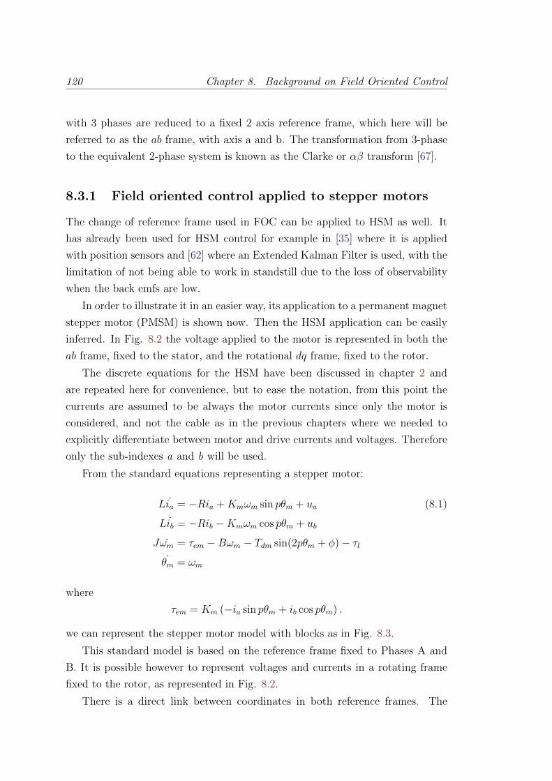
120 Chapter 8. Background on Field Oriented Control
with 3 phases are reduced to a fixed 2 axis reference frame, which here will be
referred to as the ab frame, with axis a and b. The transformation from 3-phase
to the equivalent 2-phase system is known as the Clarke or αβ transform [67].
8.3.1 Field oriented control applied to stepper motors
The change of reference frame used in FOC can be applied to HSM as well. It
has already been used for HSM control for example in [35] where it is applied
with position sensors and [62] where an Extended Kalman Filter is used, with the
limitation of not being able to work in standstill due to the loss of observability
when the back emfs are low.
In order to illustrate it in an easier way, its application to a permanent magnet
stepper motor (PMSM) is shown now. Then the HSM application can be easily
inferred. In Fig. 8.2 the voltage applied to the motor is represented in both the
ab frame, fixed to the stator, and the rotational dq frame, fixed to the rotor.
The discrete equations for the HSM have been discussed in chapter 2 and
are repeated here for convenience, but to ease the notation, from this point the
currents are assumed to be always the motor currents since only the motor is
considered, and not the cable as in the previous chapters where we needed to
explicitly differentiate between motor and drive currents and voltages. Therefore
only the sub-indexes a and b will be used.
From the standard equations representing a stepper motor:
Lia = −Ria +Kmωm sin pθm + ua (8.1)
Lib = −Rib −Kmωm cos pθm + ub
Jωm = τem −Bωm − Tdm sin(2pθm + φ)− τl˙θm = ωm
where
τem = Km (−ia sin pθm + ib cos pθm) .
we can represent the stepper motor model with blocks as in Fig. 8.3.
This standard model is based on the reference frame fixed to Phases A and
B. It is possible however to represent voltages and currents in a rotating frame
fixed to the rotor, as represented in Fig. 8.2.
There is a direct link between coordinates in both reference frames. The
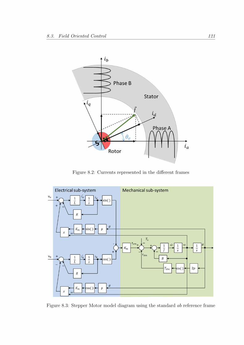
8.3. Field Oriented Control 121
Figure 8.2: Currents represented in the different frames
Figure 8.3: Stepper Motor model diagram using the standard ab reference frame
122 Chapter 8. Background on Field Oriented Control
conversion from the ab frame to the dq frame is called the direct Park Transform:
ud = uacos(θe) + ubsin(θe) (8.2)
uq = −uasin(θe) + ubcos(θe)
And the conversion from the dq to the ab frame is called the inverse Park Trans-
form:
ua = udcos(θe)− uqsin(θe) (8.3)
ub = udsin(θe) + uqcos(θe)
If this conversion, and the equivalent for the currents, is applied to the equations
(8.1), the model of the motor in the dq frame is obtained, given by the following
equations and represented in Fig. 8.4.
Lid = −Rid + pLiqωm + ud (8.4)
Liq = −Riq − pLidωm + uq −Kmωm
Jωm = Kmiq −Bωm − Tdm sin(2pθm + φ)− τl˙θm = ωm
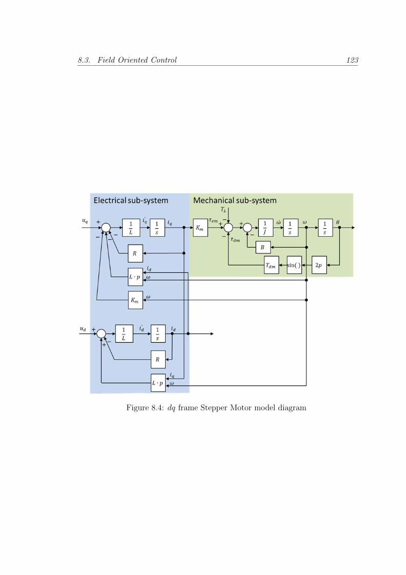
8.3. Field Oriented Control 123
Figure 8.4: dq frame Stepper Motor model diagram

Chapter 9
Control of stepper motors with
Field Oriented Control
9.1 Introduction
In this chapter the FOC applied to stepper motors is presented. First the control
scheme and tuning are described with the main practical issues for its implemen-
tation. Then the switch proposed to pass from closed to open position loop, and
finally the application in one of the LHC collimators.
9.2 Control scheme description and tuning pro-
cedure
The control scheme is implemented in several steps, starting by the most internal
layer and adding layers on top once the bottom one is working appropriately.
9.2.1 Decoupling of the current control
Looking back at Fig. 8.4, we can see that the currents id and iq are coupled. Since
the signals coupling them are available it seems logical to try to compensate for
it. In Fig. 9.1 the system including this decoupling is represented. The part
in yellow is implemented in the DSP Drive in such a way that it cancels the
corresponding physical part marked in purple.
To achieve this, the drive adds to the desired ulind and ulinq the quantities udecdand udecq respectively in order to compensate for the corresponding terms, with
124
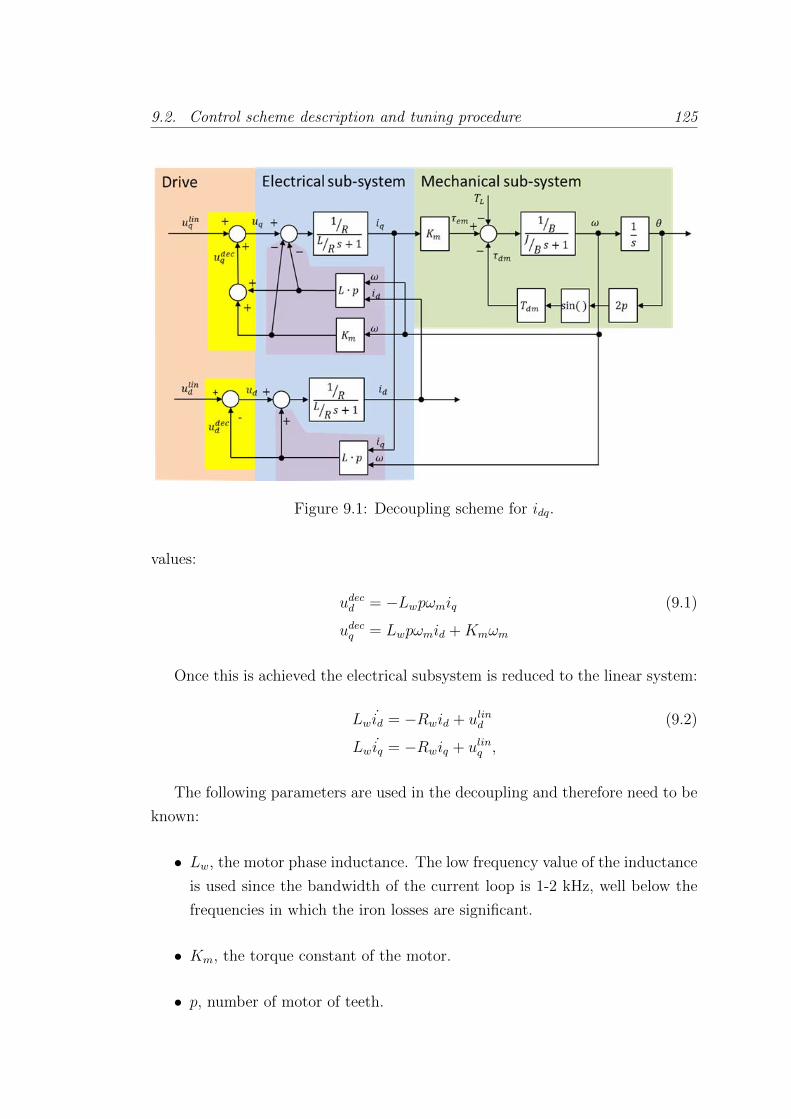
9.2. Control scheme description and tuning procedure 125
Figure 9.1: Decoupling scheme for idq.
values:
udecd = −Lwpωmiq (9.1)
udecq = Lwpωmid +Kmωm
Once this is achieved the electrical subsystem is reduced to the linear system:
Lw id = −Rwid + ulind (9.2)
Lw iq = −Rwiq + ulinq ,
The following parameters are used in the decoupling and therefore need to be
known:
• Lw, the motor phase inductance. The low frequency value of the inductance
is used since the bandwidth of the current loop is 1-2 kHz, well below the
frequencies in which the iron losses are significant.
• Km, the torque constant of the motor.
• p, number of motor of teeth.
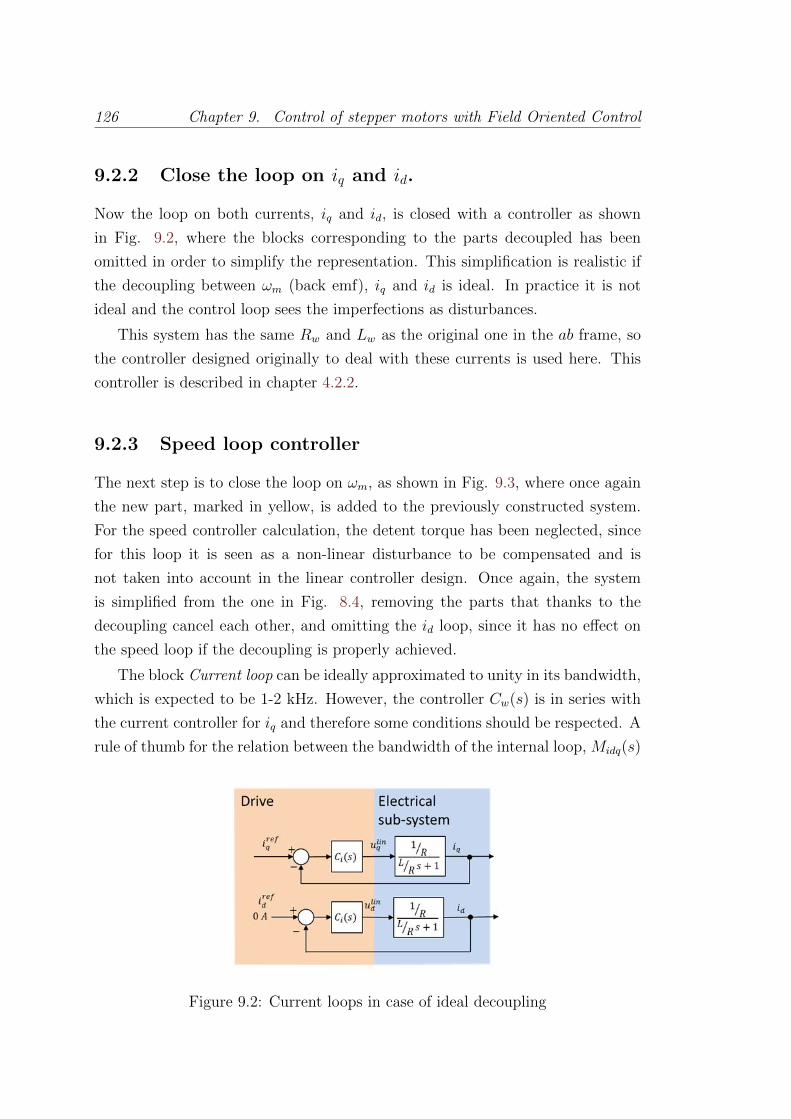
126 Chapter 9. Control of stepper motors with Field Oriented Control
9.2.2 Close the loop on iq and id.
Now the loop on both currents, iq and id, is closed with a controller as shown
in Fig. 9.2, where the blocks corresponding to the parts decoupled has been
omitted in order to simplify the representation. This simplification is realistic if
the decoupling between ωm (back emf), iq and id is ideal. In practice it is not
ideal and the control loop sees the imperfections as disturbances.
This system has the same Rw and Lw as the original one in the ab frame, so
the controller designed originally to deal with these currents is used here. This
controller is described in chapter 4.2.2.
9.2.3 Speed loop controller
The next step is to close the loop on ωm, as shown in Fig. 9.3, where once again
the new part, marked in yellow, is added to the previously constructed system.
For the speed controller calculation, the detent torque has been neglected, since
for this loop it is seen as a non-linear disturbance to be compensated and is
not taken into account in the linear controller design. Once again, the system
is simplified from the one in Fig. 8.4, removing the parts that thanks to the
decoupling cancel each other, and omitting the id loop, since it has no effect on
the speed loop if the decoupling is properly achieved.
The block Current loop can be ideally approximated to unity in its bandwidth,
which is expected to be 1-2 kHz. However, the controller Cw(s) is in series with
the current controller for iq and therefore some conditions should be respected. A
rule of thumb for the relation between the bandwidth of the internal loop, Midq(s)
Figure 9.2: Current loops in case of ideal decoupling
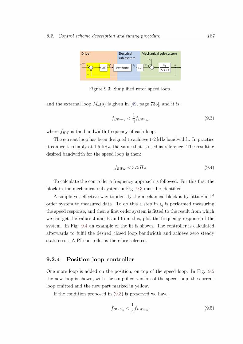
9.2. Control scheme description and tuning procedure 127
Figure 9.3: Simplified rotor speed loop
and the external loop Mω(s) is given in [49, page 733], and it is:
fBWωm <1
4fBWidq (9.3)
where fBW is the bandwidth frequency of each loop.
The current loop has been designed to achieve 1-2 kHz bandwidth. In practice
it can work reliably at 1.5 kHz, the value that is used as reference. The resulting
desired bandwidth for the speed loop is then:
fBWω < 375Hz (9.4)
To calculate the controller a frequency approach is followed. For this first the
block in the mechanical subsystem in Fig. 9.3 must be identified.
A simple yet effective way to identify the mechanical block is by fitting a 1st
order system to measured data. To do this a step in iq is performed measuring
the speed response, and then a first order system is fitted to the result from which
we can get the values J and B and from this, plot the frequency response of the
system. In Fig. 9.4 an example of the fit is shown. The controller is calculated
afterwards to fulfil the desired closed loop bandwidth and achieve zero steady
state error. A PI controller is therefore selected.
9.2.4 Position loop controller
One more loop is added on the position, on top of the speed loop. In Fig. 9.5
the new loop is shown, with the simplified version of the speed loop, the current
loop omitted and the new part marked in yellow.
If the condition proposed in (9.3) is preserved we have:
fBWθm <1
4fBWωm , (9.5)

128 Chapter 9. Control of stepper motors with Field Oriented Control
Figure 9.4: Fit of the system step response to a first order system
Figure 9.5: θm loop simplified
and the transfer function from ωrefm to ωm is approximately equal to unity for
the desired bandwidth of θm. If this condition is fulfilled, it suffices to use a
proportional controller.
9.2.5 Control scheme description
The block representations of the system shown in the chapter so far are an ab-
straction of the real system, since even though the representation in the rotating
frame is valid and coherent with it, the voltage can only be applied to the motor
phases in the stator axes a and b. A block representation of the complete FOC
system is depicted in Fig. 9.6, with the physical parts represented without the
abstraction, and therefore including the coordinates transformation blocks.
This representation matches with the real system, where the h-bridge and
the motor are represented by their own blocks and the sensors and DSP drive
implement the rest of the blocks.
The blocks Cθ(s) and Cω(s) are respectively the controllers obtained for the
position and the speed loops. The blocks Ci(s) are the current controllers. The

9.2. Control scheme description and tuning procedure 129
decoupling signals has been added to the control action calculated by the current
controllers, resulting in uq and ud, the control action voltages to be applied to
the system in the dq axis frame. The Park transform and Inverse Park transform
blocks are in charge of the change of coordinates between the dq and the ab
frames. The control action voltages ua and ub, obtained with the inverse Park
transform from uq and ud, are applied to the h-bridge as a PWM to the appropiate
MOSFETS.
To ease the understanding of the scheme, the position loop has been marked
in blue, the speed loop in green, and the decoupling terms in orange.
A block particular to this realization of the FOC applied to HSM is the Ref-
erence Generation FOC. Since the goal is to have a drive that can be replaced
by the current standard stepping drives, it is desired to keep the interface of the
latter ones. Therefore, the reference generation block provides the θrefm from the
steps and direction received and depends on the stepping mode selected (full-step,
half-step, ...).
Sampling frequency
The different new blocks meant to be implemented in the DSP are discretized
first with the Bilinear transform. The current controllers are implemented as
described in section 4.2.2. For the speed controller, the speed loop bandwidth
was intended to be 375 Hz as we saw in the section 9.2.3. In [28, page 452] a rule
of thumb is given to decide the sampling frequency of the digital controller, as:
fcont > 20fclosedloopBW (9.6)
This yields a sampling rate of at least 7.5 kHz. For simplicity in the implemen-
tation the position loop is executed in the same timed interrupt as the speed
controller.

130 Chapter 9. Control of stepper motors with Field Oriented Control
Figure 9.6: FOC blocks scheme

9.2. Control scheme description and tuning procedure 131
9.2.6 Performance achieved
The control scheme is implemented and tested with a real LHC collimator motor.
The stepping profile from Fig. 8.1 is applied and the result is shown in Fig. 9.7.
The reduction in overshoot and settling time compared to open loop is clear.
A comparison of the performance between both control methods is done with
a test repeating a step in full-step mode 10 times and measuring the position of
the motor, shown in Fig. 9.8 for the standard stepping mode and Fig. 9.9 for
FOC.
FOC represents clearly better results with improvements in the settling time
from 6.76 ms to 1.40 ms, in the overshoot from 81.96% to 2.72% and in the
standard deviation of the steady state positioning error from 0.088 degrees to
0.015 degrees, on average.
Figure 9.7: Full-step mode rotor position and speed acquisition, using closed-loopposition control
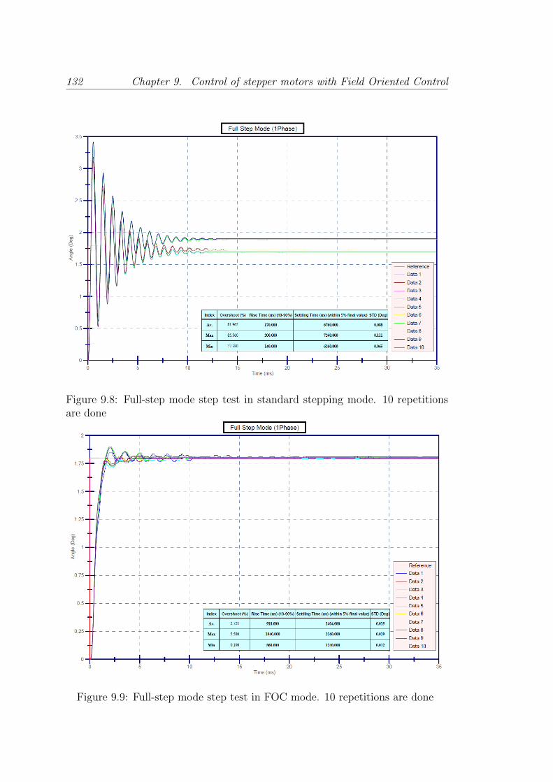
132 Chapter 9. Control of stepper motors with Field Oriented Control
Figure 9.8: Full-step mode step test in standard stepping mode. 10 repetitionsare done
Figure 9.9: Full-step mode step test in FOC mode. 10 repetitions are done

9.3. Practical issues 133
9.3 Practical issues
Some issues particular to the application are worth mentioning since they have
proved to be fundamental to be properly addressed.
9.3.1 θ0 calibration method
The position sensors used in the collimators are mainly resolvers. The developed
DSP Drive has an encoder input and therefore a resolver-to-encoder converter is
necessary to use the sensor information in the loop.
The zero of the sensor, whether it is the resolver or the encoders used in the
laboratory, and the electrical zeros of the rotor are not aligned, forming an angle
that we will call θ0. It is necessary to know this angle in order to apply properly
the Park transform, which is used in all the controllers in the scheme.
A procedure to perform the θ0 measurement, which is possible even when we
measure with the motor coupled to a system, has been developed, with the goal
of avoiding abrupt mechanical shocks to the coupled systems.
A diagram of this procedure is shown in Fig. 9.10. On each cycle, we perform
steps in standard open loop, at low current depending on the application to
avoid brusque movements, until the step corresponding to θe = 0 is reached.
This position is the one with ia = I and ib = 0, since with these currents applied,
τem is zero only if θe = 0, and it only deviates if a load torque is applied to the
shaft. This load torque is in fact compensated by τem since θe is different from
zero. To minimize this difference, the next step in the procedure is to increase
the current to the maximum allowed. Since this increment of current and, in
consequence, τem, is done once the final position is achieved, no mechanical step
is applied, and only θe made as close to 0 as it can be achieved in open loop.
After a small time to let any transient extinguish, the angle is measured and
the cycle repeated, until the 50 electrical turns have been measured, stepping in
both directions. Once it is done, θ0 is obtained by averaging the measured angles,
converted to electrical turns.
9.3.2 Velocity estimation
Velocity estimation using an encoder is not a straightforward problem when the
speed is low or zero [68]. The intuitive solution to get speed from position is to
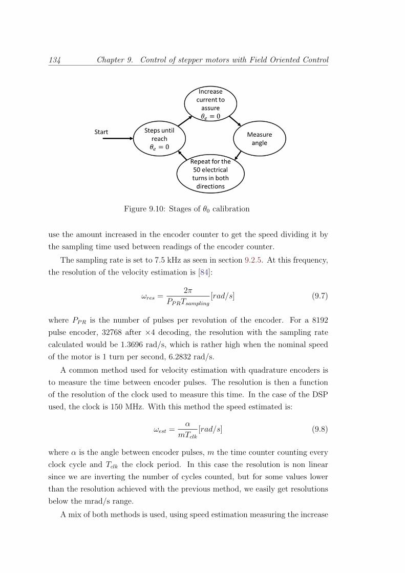
134 Chapter 9. Control of stepper motors with Field Oriented Control
Figure 9.10: Stages of θ0 calibration
use the amount increased in the encoder counter to get the speed dividing it by
the sampling time used between readings of the encoder counter.
The sampling rate is set to 7.5 kHz as seen in section 9.2.5. At this frequency,
the resolution of the velocity estimation is [84]:
ωres =2π
PPRTsampling[rad/s] (9.7)
where PPR is the number of pulses per revolution of the encoder. For a 8192
pulse encoder, 32768 after ×4 decoding, the resolution with the sampling rate
calculated would be 1.3696 rad/s, which is rather high when the nominal speed
of the motor is 1 turn per second, 6.2832 rad/s.
A common method used for velocity estimation with quadrature encoders is
to measure the time between encoder pulses. The resolution is then a function
of the resolution of the clock used to measure this time. In the case of the DSP
used, the clock is 150 MHz. With this method the speed estimated is:
ωest =α
mTclk[rad/s] (9.8)
where α is the angle between encoder pulses, m the time counter counting every
clock cycle and Tclk the clock period. In this case the resolution is non linear
since we are inverting the number of cycles counted, but for some values lower
than the resolution achieved with the previous method, we easily get resolutions
below the mrad/s range.
A mix of both methods is used, using speed estimation measuring the increase
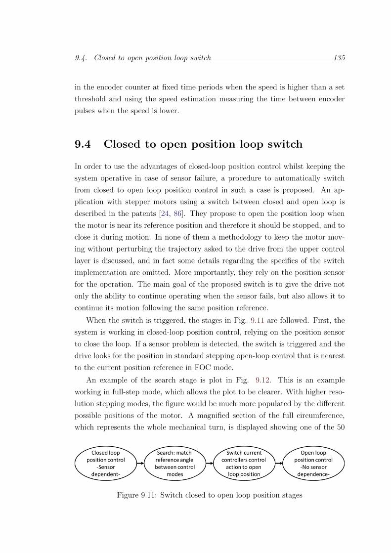
9.4. Closed to open position loop switch 135
in the encoder counter at fixed time periods when the speed is higher than a set
threshold and using the speed estimation measuring the time between encoder
pulses when the speed is lower.
9.4 Closed to open position loop switch
In order to use the advantages of closed-loop position control whilst keeping the
system operative in case of sensor failure, a procedure to automatically switch
from closed to open loop position control in such a case is proposed. An ap-
plication with stepper motors using a switch between closed and open loop is
described in the patents [24, 86]. They propose to open the position loop when
the motor is near its reference position and therefore it should be stopped, and to
close it during motion. In none of them a methodology to keep the motor mov-
ing without perturbing the trajectory asked to the drive from the upper control
layer is discussed, and in fact some details regarding the specifics of the switch
implementation are omitted. More importantly, they rely on the position sensor
for the operation. The main goal of the proposed switch is to give the drive not
only the ability to continue operating when the sensor fails, but also allows it to
continue its motion following the same position reference.
When the switch is triggered, the stages in Fig. 9.11 are followed. First, the
system is working in closed-loop position control, relying on the position sensor
to close the loop. If a sensor problem is detected, the switch is triggered and the
drive looks for the position in standard stepping open-loop control that is nearest
to the current position reference in FOC mode.
An example of the search stage is plot in Fig. 9.12. This is an example
working in full-step mode, which allows the plot to be clearer. With higher reso-
lution stepping modes, the figure would be much more populated by the different
possible positions of the motor. A magnified section of the full circumference,
which represents the whole mechanical turn, is displayed showing one of the 50
Figure 9.11: Switch closed to open loop position stages
136 Chapter 9. Control of stepper motors with Field Oriented Control
electric turns in the HSM used. The electrical turn, corresponding to 7.2 degrees,
is divided in full-step mode into 4 steps, represented in the figure by green arrows
and numbered. The positions in the electrical turn are repeated continuously, 50
times along the whole mechanical turn. At the moment that the search stage is
run, the FOC was following the reference θrefm , represented by a orange arrow in
the figure. The algorithm looks for the nearest angle corresponding to a step in
the stepping mode selected, and the current references are set accordingly. Once
this is done, the switch of control strategy to apply to the motors, shown in 9.13,
can be made to begin operating in standard stepping mode (open-loop position
control).
In this way, when the system actually switches to open loop control, the motor
moves by a maximum angle equal to half the step size. Finally, the drive continues
operating in open loop as a standard stepper motor drive.
The Fig. 9.13 shows the scheme of the switch implementation. The switch
can be in either position 1, driving the motor in standard stepping mode, with the
position control in open-loop, or in position 2, using FOC. The voltage applied
to the motor phases depends on the working mode selected, and the transition
between modes follows the procedure described above.
In Fig. 9.14 the result of using the switch during the motor operation is
shown, and in Fig. 9.15 a zoom of the transition can be found. The motor
position continues its way without perceptible difference, aside of the inherent
behaviour difference between closed and open loop position control.
The reversed situation, switching from open to closed loop position, is also
possible and in fact it has been implemented for completeness, although it has
no direct practical application. In this case, the main issue to pay attention to is
the transfer from open to closed loop of the controller, which has to implement
a bumpless transfer. This is a known problem in PID control [65] and has to be
addressed to avoid the integrator in the PI controller from accumulating error
when the loop is not closed and therefore the control action calculated by the
controller is not being applied. In Fig. 9.16 the motion of the motor is shown
with the drive switching back and forth between closed and open loop modes. The
mode in a specific instant can be inferred from the magnitude of the instantaneous
speed, having clearly bigger oscillations in open loop. In Fig. 9.17 a zoom of the
transition from open to closed loop is shown.
The phase currents during the switch from closed to open-loop can be seen in
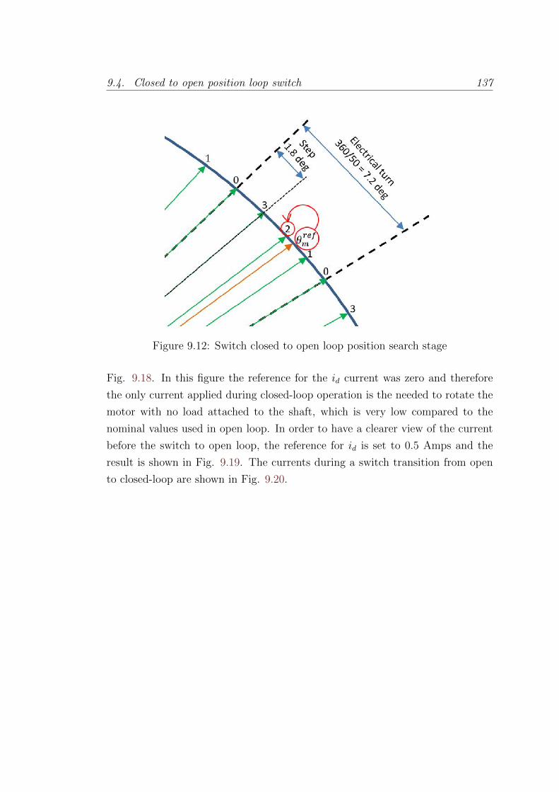
9.4. Closed to open position loop switch 137
Figure 9.12: Switch closed to open loop position search stage
Fig. 9.18. In this figure the reference for the id current was zero and therefore
the only current applied during closed-loop operation is the needed to rotate the
motor with no load attached to the shaft, which is very low compared to the
nominal values used in open loop. In order to have a clearer view of the current
before the switch to open loop, the reference for id is set to 0.5 Amps and the
result is shown in Fig. 9.19. The currents during a switch transition from open
to closed-loop are shown in Fig. 9.20.
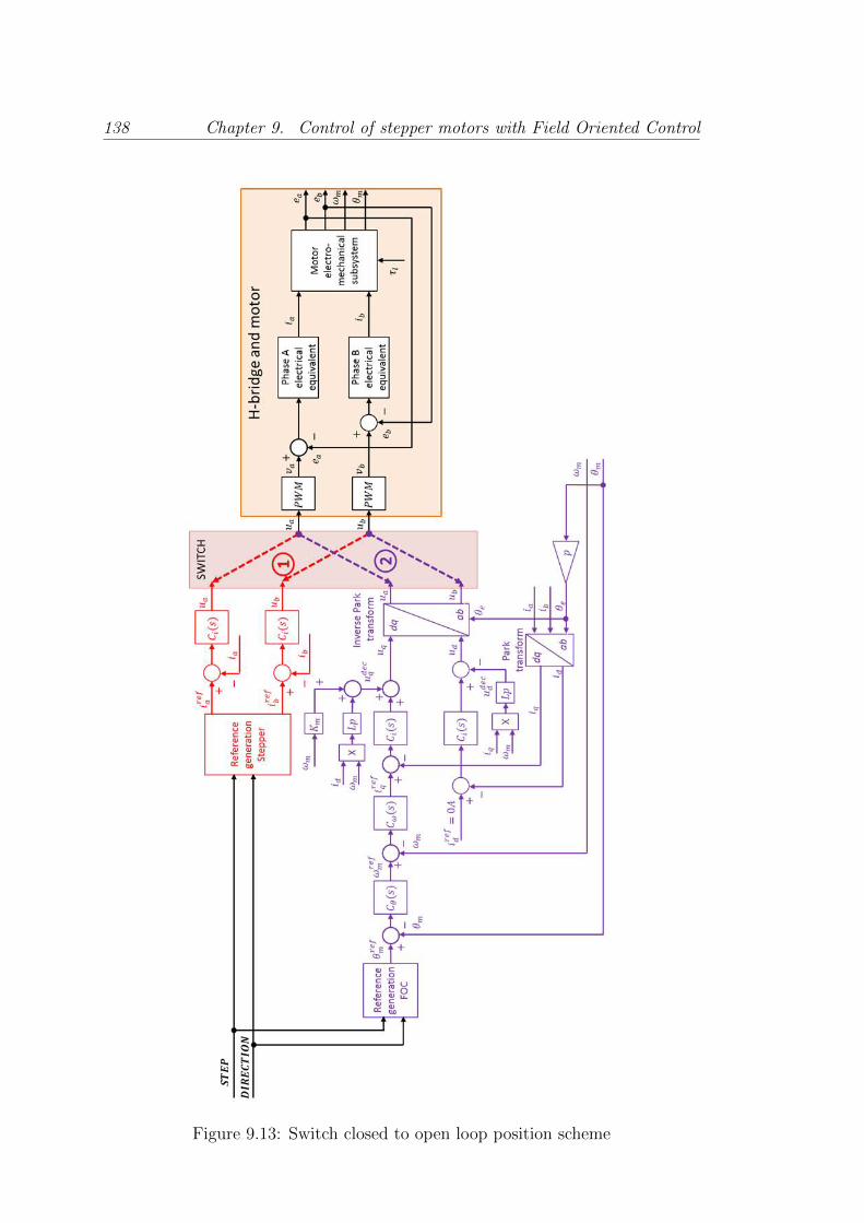
138 Chapter 9. Control of stepper motors with Field Oriented Control
Figure 9.13: Switch closed to open loop position scheme

9.4. Closed to open position loop switch 139
Figure 9.14: Switch from closed to open loop position control in operation
Figure 9.15: Zoom of the switch from closed to open loop position control inoperation
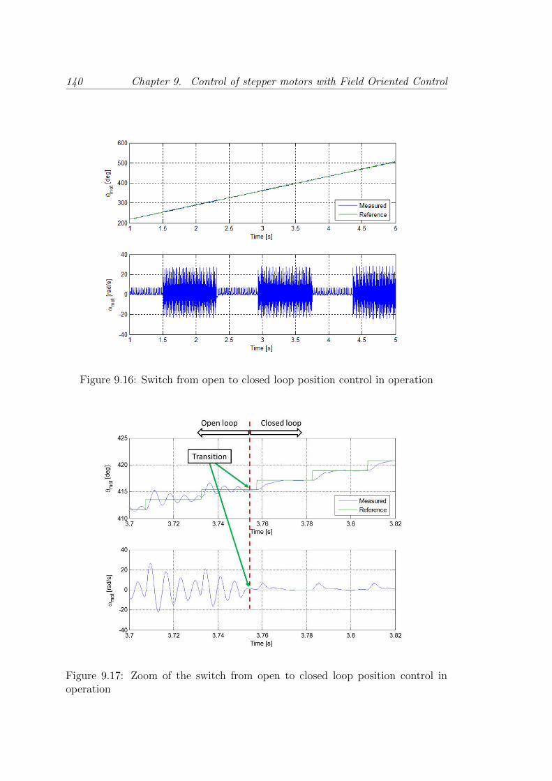
140 Chapter 9. Control of stepper motors with Field Oriented Control
Figure 9.16: Switch from open to closed loop position control in operation
Figure 9.17: Zoom of the switch from open to closed loop position control inoperation
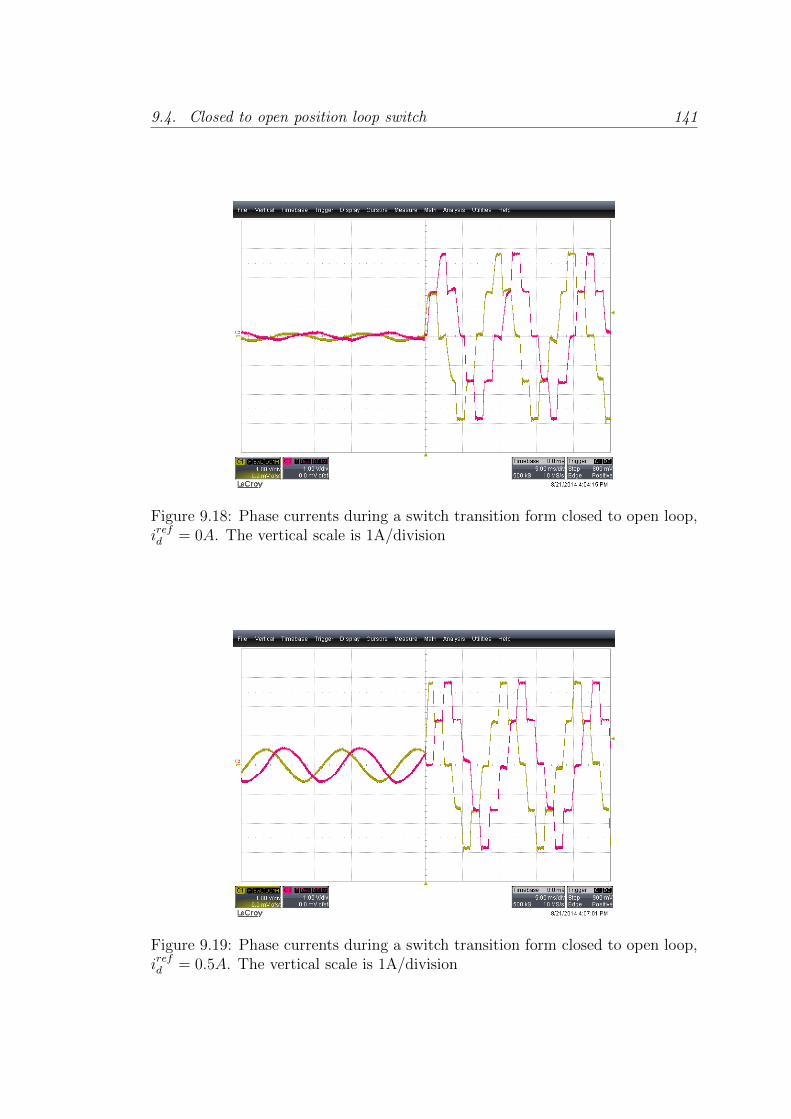
9.4. Closed to open position loop switch 141
Figure 9.18: Phase currents during a switch transition form closed to open loop,irefd = 0A. The vertical scale is 1A/division
Figure 9.19: Phase currents during a switch transition form closed to open loop,irefd = 0.5A. The vertical scale is 1A/division

142 Chapter 9. Control of stepper motors with Field Oriented Control
Figure 9.20: Phase currents during a switch transition form open to closed loop,irefd = 0.5A. The vertical scale is 1A/division
9.5 Use of FOC and the switch in the LHC Col-
limators
The first place where the new control approach was tested was in the LHC col-
limators. As explained in section 3.3 and again in this part, the mechanics in
the LHC collimators can wear due to the strong vibrations induced by the motor
running in standard stepping mode. It is probable that such wear may force the
replacement of collimators before it was foreseen, with high costs. It is desirable
to extend the lifetime of the collimator mechanics, and therefore the FOC work-
ing mode is under test in an LHC collimator linear stage like the one shown in
Fig. 9.21.
In the collimator mechanism, the motor moves a worm screw that moves a
block held by a spring linearly. As the block is moved away from the initial
position, the force applied by the spring increases. For small movements, this
spring can be seen as an external load disturbance. The FOC position controller
should reject this disturbance and keep the steady-state position error near to
zero. Instead, the standard stepping mode relies on the constant application of a
torque higher than the maximum external torque, but even if the electromagnetic
torque is high, the positioning error increases proportionally to the linear position,
due to the spring nature.
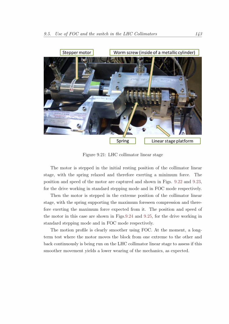
9.5. Use of FOC and the switch in the LHC Collimators 143
Figure 9.21: LHC collimator linear stage
The motor is stepped in the initial resting position of the collimator linear
stage, with the spring relaxed and therefore exerting a minimum force. The
position and speed of the motor are captured and shown in Figs. 9.22 and 9.23,
for the drive working in standard stepping mode and in FOC mode respectively.
Then the motor is stepped in the extreme position of the collimator linear
stage, with the spring supporting the maximum foreseen compression and there-
fore exerting the maximum force expected from it. The position and speed of
the motor in this case are shown in Figs.9.24 and 9.25, for the drive working in
standard stepping mode and in FOC mode respectively.
The motion profile is clearly smoother using FOC. At the moment, a long-
term test where the motor moves the block from one extreme to the other and
back continuously is being run on the LHC collimator linear stage to assess if this
smoother movement yields a lower wearing of the mechanics, as expected.

144 Chapter 9. Control of stepper motors with Field Oriented Control
Figure 9.22: Motor position in the collimator linear stage working in open-loop,spring relaxed
Figure 9.23: Motor position in the collimator linear stage using FOC, springrelaxed
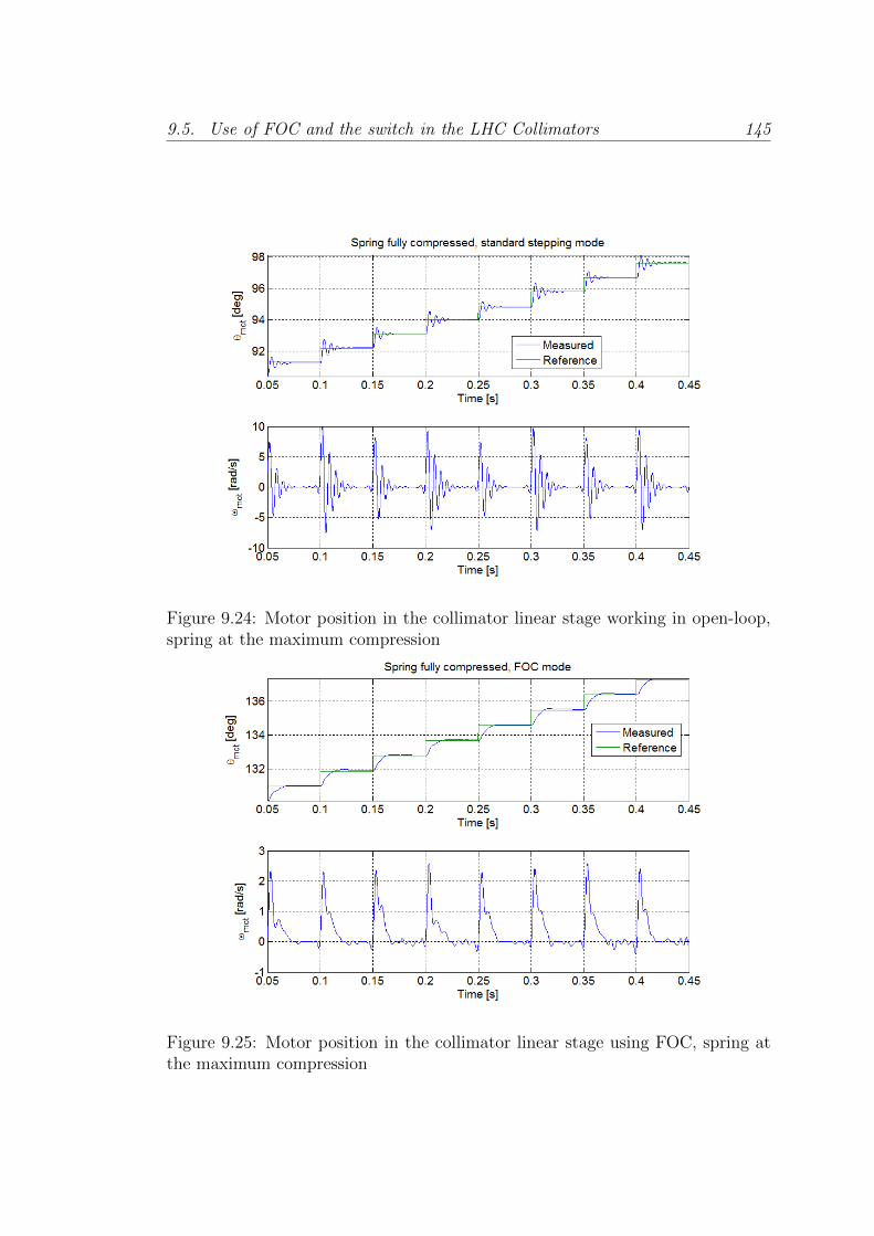
9.5. Use of FOC and the switch in the LHC Collimators 145
Figure 9.24: Motor position in the collimator linear stage working in open-loop,spring at the maximum compression
Figure 9.25: Motor position in the collimator linear stage using FOC, spring atthe maximum compression
146 Chapter 9. Control of stepper motors with Field Oriented Control
9.6 Conclusions
In this chapter the implementation and tuning of the Field Oriented Control ap-
plied to stepper motors has been described. A method to switch between closed-
loop position control (FOC) and open-loop position control (standard stepping
mode) has been proposed and validated constituting an original contribution of
this work. With this switching system, the drive can be used by the upper con-
trol layers sending the commands to the drive without them noticing the position
control type used by the drive. The motion profile is equally followed by the
motor, with the only difference of a smoothed motion and reduced error thanks
to the closed-loop control.
Using FOC has proved to be significantly smoother, representing a much less
aggressive option of motor control for the mechanics. This is very attractive for
the applications at CERN, were extending the lifespan of the mechanical systems
represents an improvement in terms of material costs and maintenance work. In
fact, it has proven to be an improvement for the positioning systems in some other
applications in addition to the LHC collimators, as presented in appendix B. This
fact combined with the proposed switched closed to open loop position control,
which allows the high reliability of the system to be maintained, constitutes an
attractive alternative to the standard stepping control.

Part IV
Output filters

Chapter 10
Introduction to Output filters
10.1 Introduction
In chapter 4 a solution to the problem of working with long cables and switched
drives was explained. This is a solution based on a digital, cable length dependent
estimation filter, thanks to which a standard switched inverter can work properly
when long cables are used to connect drive and motor. This method allows good
motor phase current control to be achieved.
However, the 3 effects described in chapter 3: drive-side large amplitude ring-
ing phenomena in the current, (Fig. 3.2), Common-Mode currents in the phase
(Fig. 3.4) and, at the motor-side of the cable, high voltage oscillations across the
motor terminals (Fig. 3.5), are still present.
A different solution from that presented in chapter 4, based on passive filtering
of the power signals, is presented in this chapter. This solution mitigates the 3
effects described above, reducing the EMI, enlarging the lifespan of the motor,
and allowing off-the-shelf motor drives to work properly in the presence of long
cables.
This solution, which is relatively well known in industry for induction and
synchronous motors, is the use of output filters, also known as LC filters. The
design presented and the use of output filters for stepper motors are an original
contribution of this thesis.
148

10.2. State of the art for output filters 149
10.2 State of the art for output filters
Output filters constitute a simple and robust solution for PWM drives feeding
electric motors through long cables. They have been broadly studied for their
application to induction and synchronous motors and are fairly standard in in-
dustry.
In [32] a broad view of the use of output filters in adjustable speed drives
is given, from the origin and modelling of the high frequency phenomena, to
the known mitigation techniques, proposing a new filter which has the common
terminal of the common-mode capacitors clamped to the dc-link rails by means
of diodes, limiting the voltage at this point to that of the dc-link and reducing
the motor terminal voltage overshoot. In [25], the mechanism producing voltage
oscillations, which can be up to twice the dc link voltage in the inverter is further
explained. It also gives summary of the most common output filter options with
their advantages -reducing high voltages and their high derivatives at the motor
terminals- and disadvantages -cost, space and reduced inverter efficiency.
Some different design constraints and rules which are referred to for the design
of the filter proposed in the next chapter are given in [83], where use of output
filters for a medium voltage application is presented; [82], where a new stage in
the filter, an LC trap intended to block the PWM frequency, is proposed; and
[91], where the details of the low pass filtering needed from the output filter to
avoid motor terminal overvoltage due to voltage reflections is studied.
The application of output filters to stepper motor has not been explored and
only one application note, [89], which proposes an LC filter for a stepper motor,
was found by the author. In this application note, the proposed LC filter is
intended to work without a long cable, and therefore the design procedure is
not sufficient to design a complete output filter for stepper motors as shall be
presented here.
A solution to reduce the over voltages when over modulation occurs, and thus
to reduce the ringing, is presented in [37], by acting on the way the PWM is
applied in the transition into and out of the over modulation. Other solution
based on passive filters is presented in [60] specially suitable when high voltages
or their derivatives are an issue for the motor insulation.

150 Chapter 10. Introduction to Output filters
10.3 Output filters
As introduced in chapter 3, when a long cable is used to connect a motor with a
drive, the latter being a switched inverter applying a PWM voltage, it behaves as
a transmission line. The mechanism producing these effects was explained there.
Output filters, a common solution in industry for AC motors working with long
cables, are summarized in the following section.
Output filters are placed at the output of the drive, between it and the cable,
as shown in Fig. 10.1.
They typically consist of 2 stages, one meant to deal with the Differential
Mode voltage and the other with the Common Mode voltage, as shown in Fig.
10.2 (the order of the stages is not necessarily as shown though it is the most
common). The purpose of both stages of the output filter is to block or reduce
the higher frequencies of the voltage applied to the cable and therefore reduce
the adverse effects caused by this combination as described in chapter 3.
For each stage there are many possible topologies [32]. Fig. 10.3 shows a
broadly used output filter, which is the starting point for the proposed filter in
the next chapter. It consists of an RLC low-pass filter for the DM stage, whereas
for the CM stage a toroidal choke is used.
These filters are characterized by their resonant frequency f0, given by:
f0 =
√1
2πLDMCDM(10.1)
Output filters are classified in two main types depending on where the resonant
frequency of the filter is set. When f0 is above the PWM switching frequency,
fPWM , the filter limits the du/dt applied to the cable, but the motor-side voltage
is still similar to the voltage drive-side. In this case they are called du/dt filters,
Figure 10.1: Typical motor-cable-drive system using an output filter.

10.3. Output filters 151
Figure 10.2: Output filter stages.
Figure 10.3: Typical two stage induction motor output filter.

152 Chapter 10. Introduction to Output filters
since they limit the du/dt values of the voltage applied to the motor.
When f0 is below fPWM , they are called sine-wave filters. The name comes
from the fact that the voltage across the motor terminal is closer to a sinusoid in
this case. Usually f0 is set at least 3 times lower than fPWM to achieve a proper
sinusoidal motor-side voltage.
For this application the resonant frequency of the filter is set well below the
PWM frequency in order to achieve a strong attenuation of the voltage applied
at this frequency. Therefore, the designed filter is of the sine-wave type.

Chapter 11
Sine Wave Filters For Stepper
Motors
11.1 Proposal
In this chapter, a procedure for the design of output filters is illustrated via a
real application. The main particularity of this application compared to that of
induction and synchronous motors, in addition to the different electrical configu-
ration, is that in stepper motors the current profile is made of steps as opposed
to a sinusoidal waveform, requiring a relatively high bandwidth compared to the
PWM frequency, making the design more challenging.
An adapted version of the filter from Fig.10.3 for a single stepper motor phase
is proposed as shown in Fig.11.1. As in the original filter, it consists of two stages,
a Common-Mode filter and a Differential-Mode filter. In the following both filter
stages are designed by adapting guidelines given in the literature for induction
motors.
11.2 Sine wave filter design
11.2.1 The application
For the design, the hybrid stepper motor and cable described in section 2.3 is used.
The drive used is an SHS Star 2000 as described in section 4.2. The equivalent
closed loop bandwidth of 1 kHz is used as reference value for the design with the
addition of intensive simulation to validate the good behaviour of the filter.
153

154 Chapter 11. Sine Wave Filters For Stepper Motors
Figure 11.1: Output filter adapted to a single stepper motor phase
The nominal angular speed of the motor is 1 mechanical turn of the shaft per
second, with a maximum peak of 10 turns per second. This corresponds to 50
and 500 electrical turns per second respectively.
11.2.2 Differential Mode Filter
The electrical circuit for a differential mode filter of a stepper motor phase is
shown in Fig.11.1. It is a low pass voltage filter whose transfer function is the
following:
Gv(s) =Vout(s)
Vin(s)=
RDMCDMs+ 1
LDMCDMs2 +RDMCDMs+ 1(11.1)
where LDM , CDM and RDM are respectively the differential mode filter induc-
tance, capacitance and resistance.
The resonant frequency of the filter is given by the expression (10.1) and the
characteristic impedance is
R0f =
√LDMCDM
(11.2)
To choose the f0 of the filter there are several guidelines. In [83] and [32] it is
proposed to take f0 10 times higher than the fundamental frequency of the voltage
applied. In induction motors this frequency is usually 50/60 Hz for fixed speed
drives. As mentioned in section 11.2.1, the maximum electrical frequency ex-
pected is 500 electrical turns per second, corresponding to a fundamental applied
voltage of 500 Hz. Following the cited rule, the DM filter should have a resonant
frequency of at least 5000 Hz in order to avoid excitation of the resonance of the
filter and attenuation of significant frequency components at frequencies higher
11.2. Sine wave filter design 155
than the fundamental due to the stepper current waveform.
A trade-off, nonetheless, exists since, in order to reduce the response to the
PWM main frequency, the filter should provide sufficient attenuation at that
frequency. The upper limit for f0 is therefore set to 1/3 of fPWM , to give an
attenuation of 18 dB at this frequency (see [32]).
In summary, the bounds for the filter frequency are set to:
f0 > 10fout = 5 kHz (11.3)
f0 <1
3fPWM = 6.66 kHz
A second constraint is found in the resistance of the filter. In [91] it is proposed
to set the resistance of the filter, RDM , equal to the characteristic impedance of
the cable, Z0:
RDM = Z0 =
√l
c(11.4)
Since at high frequencies the capacitor CDM represents a short circuit and the
inductor LDM an open circuit, by setting the filter resistance to this value, the
source reflection coefficient, given by:
Γs =Rs − Z0
Rs + Z0
,
is 0, as the resistor absorbs the reflected energy.
Given these 2 constraints, there is only one more required to fix the value of
the 3 filter components. It is set in such a way that the transfer function of the
filter is critically damped (see [82]) to a value of:
RDM =
√4LDMCDM
(11.5)
With these 3 constraints, the combinations of RDM , LDM and CDM corre-
sponding to the extreme values allowed for f0 are found from equations (11.1) for
the 3dB attenuation at the cutoff frequency, (11.4) and (11.5).
These values are tested in simulation. With this filter the drive is capable
of working with a 720 meter cable, as shown in Fig.11.2. In the upper plot the
motor side current is shown, in the centre the motor side voltage and in the lower
plot the power dissipated in the filter resistor. In Fig.11.3 a zoomed version of
the simulation results is shown. An important step is achieved, since the drive is
156 Chapter 11. Sine Wave Filters For Stepper Motors
working as desired while without the filter the currents were far from the reference
values, as shown in Fig.3.3.
However, after extensive simulation, the power consumption in the filter resis-
tor following these constraints was found to be rather high compared to similar
performances achieved with lower power consumption. If the constraint (11.4)
on the filter resistance, RDM , is relaxed and values in its proximity are tested, it
is found via simulation that better results in terms of power consumption can be
achieved.
The criteria (11.4) is therefore replaced by minimising the power consumption
in the filter resistance. Just with these constraints, the optimum is found by using
an arbitrarily large inductance value and the corresponding capacitance value
to fulfil the filter cutoff frequency constraint. Therefore, one more constraint,
avoiding excessively big values of inductance, is used and the obtained values,
shown in Table 11.1, are found to yield good results.
In Fig.11.4 the results obtained in simulation are shown and compared with
the best of the previous 2 sets of filter values obtained with the original (11.3)-
(11.5) constraints set.
With this filter, the power consumption is greatly reduced. This feature allows
the filter to be implemented in a more compact space since the heat dissipation
is less demanding.
The steady-state error observed in figures 11.2, 11.3 and 11.4 is due to the
current control scheme used by the SHS Drive. This control, described in section
4.2, uses the drive-side current to close the current loop in its comparator, with
the ringing superimposed (Fig. 3.2), and therefore there is a steady-state error
in the motor-side current corresponding to the amplitude of the superimposed
current ringing. In Fig. 11.5 it can be observed how the drive-side current peaks
reach values very near the reference, the fixed values 0, 2 and 2√
2 Amps, whilst
the motor-side current remains somewhat below this value.
Table 11.1: Filter component values.Component Value
RDM 440 [Ω]LDM 5.0 [mH]CDM 0.12 [µF ]f0 6.5 [kHz]R0f 204.12 [Ω]
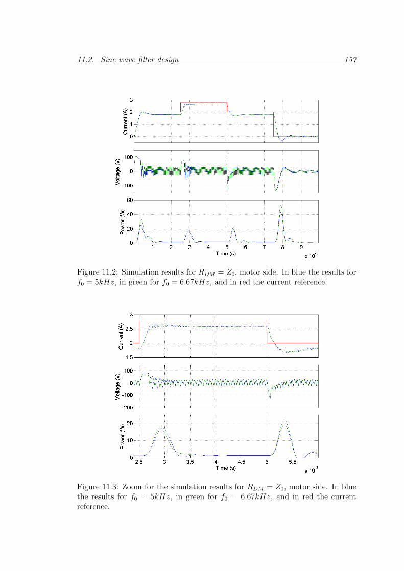
11.2. Sine wave filter design 157
Figure 11.2: Simulation results for RDM = Z0, motor side. In blue the results forf0 = 5kHz, in green for f0 = 6.67kHz, and in red the current reference.
Figure 11.3: Zoom for the simulation results for RDM = Z0, motor side. In bluethe results for f0 = 5kHz, in green for f0 = 6.67kHz, and in red the currentreference.
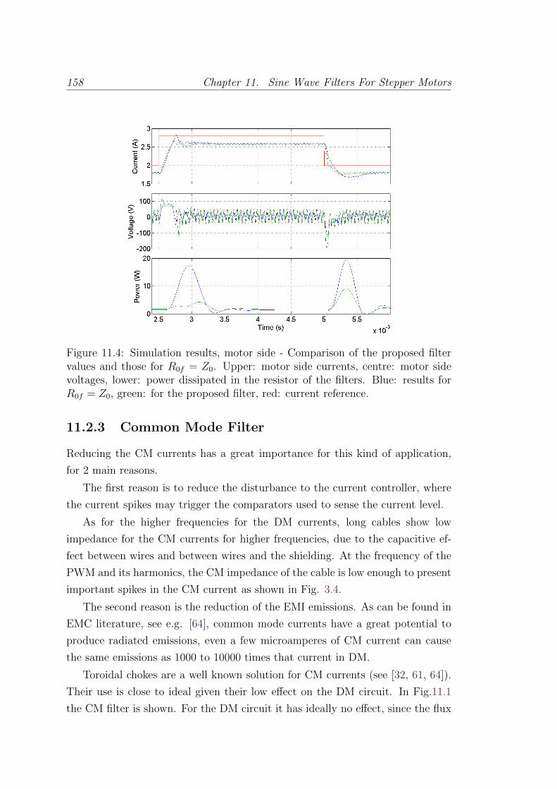
158 Chapter 11. Sine Wave Filters For Stepper Motors
Figure 11.4: Simulation results, motor side - Comparison of the proposed filtervalues and those for R0f = Z0. Upper: motor side currents, centre: motor sidevoltages, lower: power dissipated in the resistor of the filters. Blue: results forR0f = Z0, green: for the proposed filter, red: current reference.
11.2.3 Common Mode Filter
Reducing the CM currents has a great importance for this kind of application,
for 2 main reasons.
The first reason is to reduce the disturbance to the current controller, where
the current spikes may trigger the comparators used to sense the current level.
As for the higher frequencies for the DM currents, long cables show low
impedance for the CM currents for higher frequencies, due to the capacitive ef-
fect between wires and between wires and the shielding. At the frequency of the
PWM and its harmonics, the CM impedance of the cable is low enough to present
important spikes in the CM current as shown in Fig. 3.4.
The second reason is the reduction of the EMI emissions. As can be found in
EMC literature, see e.g. [64], common mode currents have a great potential to
produce radiated emissions, even a few microamperes of CM current can cause
the same emissions as 1000 to 10000 times that current in DM.
Toroidal chokes are a well known solution for CM currents (see [32, 61, 64]).
Their use is close to ideal given their low effect on the DM circuit. In Fig.11.1
the CM filter is shown. For the DM circuit it has ideally no effect, since the flux
11.3. Experimental validation 159
generated by the current in the DM current flowing to the motor is cancelled by
that generated by the current flowing back from the motor. Instead, with respect
to the CM circuit it represents twice the inductance since the CM current is equal
in both wires and generates flux in the same direction. The flux generated adds
up therefore and is double for a specific CM current.
The CM inductance is in series with the rest of the CM circuit. The goal is to
reduce the CM current resulting from the PWM voltage and its harmonics. We
focus therefore on the impedance of the CM inductance at this frequency. The
magnitude of the impedance is given by:
|ZCM | = |LCMjω| (11.6)
To get a high attenuation from the first harmonic of the PWM frequency, of
at least between 1/1000 to 1/10000, the required inductance should be between
8 and 80 mH.
11.3 Experimental validation
An output filter prototype with the component values detailed in Table 11.1 and a
20 mH toroidal choke was built and tested with the drive and the motor described
in sections 4.2 and 2.3 respectively. The results of its performance are detailed
in the following.
11.3.1 Effect of the filter on the motor currents
In Fig.11.5, the currents for a phase are shown, and in Fig.11.6 a zoom is pre-
sented. It can be appreciated how the peak-to-peak amplitude of the oscillations
of the drive side current, now approximately 0.5 A, has been greatly reduced with
respect to Fig.3.2, where they reached an amplitude of over 3.5 A.
Furthermore, in the case with the filter, the frequency of the ripple is that of
the PWM, and the oscillation at the 3rd harmonic of the PWM frequency is not
appreciable anymore, as it was before.
11.3.2 Effect of the filter on the motor voltages
The voltages achieved at the terminals of the motor are shown in Fig.11.7. The
overvoltages have been reduced and the peaks now only exceed the power supply
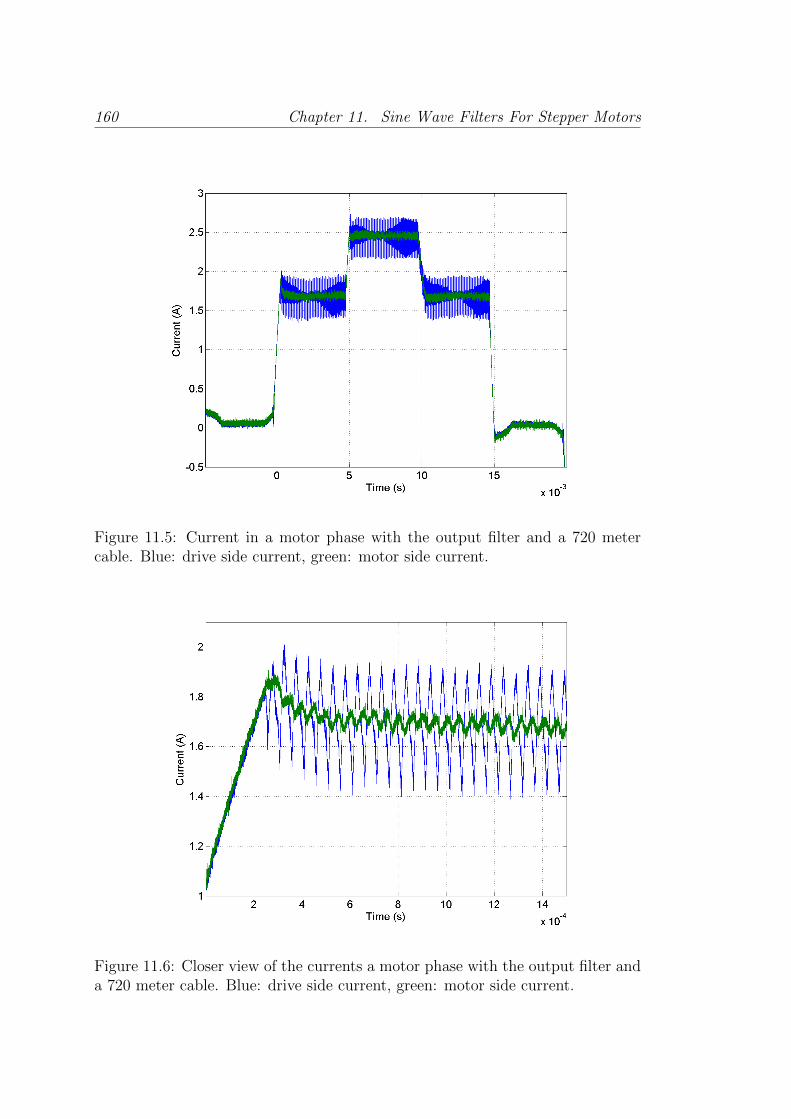
160 Chapter 11. Sine Wave Filters For Stepper Motors
Figure 11.5: Current in a motor phase with the output filter and a 720 metercable. Blue: drive side current, green: motor side current.
Figure 11.6: Closer view of the currents a motor phase with the output filter anda 720 meter cable. Blue: drive side current, green: motor side current.

11.3. Experimental validation 161
voltage, 135V , when there is a step in the current signals, and it is immediately
reduced below this value. The amplitude in the steady state regions is significantly
reduced compared to that found without a filter, as in Fig. 3.5. In Fig. 11.8 both
voltages are compared and the difference is easily appreciable.
11.3.3 Effect of the filter on the positioning
The repeatability is measured as the standard deviation of the angular steady
state positioning error after each step, σ, normalised by the target angle step,
θangle. The target step angle when working with half-step stepping mode, as is
done during the tests, is 0.9 degrees. 1600 steps are performed on each test.
The positioning repeatability results are shown in Fig.11.9 for the drive with
neither a long cable nor the output filter, since as seen previously the drive does
not work properly with a long cable and without a filter, and in Fig.11.10 for the
drive working with both the output filter and a 720 meter cable. In Table 11.2
the numerical results are summarised.
The improvement introduced by the use of the output filter can be appreciated
from the positioning repeatability, yielding better results than even without a long
cable.
11.3.4 EMI
A comparative measurement is performed to assess the EMI emissions. A section
of the cable shielding is stripped off and a spiral antenna is situated over it. This
antenna complies with the standard IEC 60478-5 Type A, and the measurement
is done over a conducting plane complying with the aforementioned standard.
The results of the emitted field are shown in Fig.11.11. The emissions are
measured for the drive with a short cable and no output filter and for the drive
with a 720 meter cable and the output filter.
There is a significant reduction of the emissions of approximately 40 dB over
the entire frequency range studied.
Table 11.2: Repeatability test results.σ[deg] σ/θtarget [%]
Short cable - No output filter 0.0583 6.5720 m cable - Output filter 0.0538 6.0
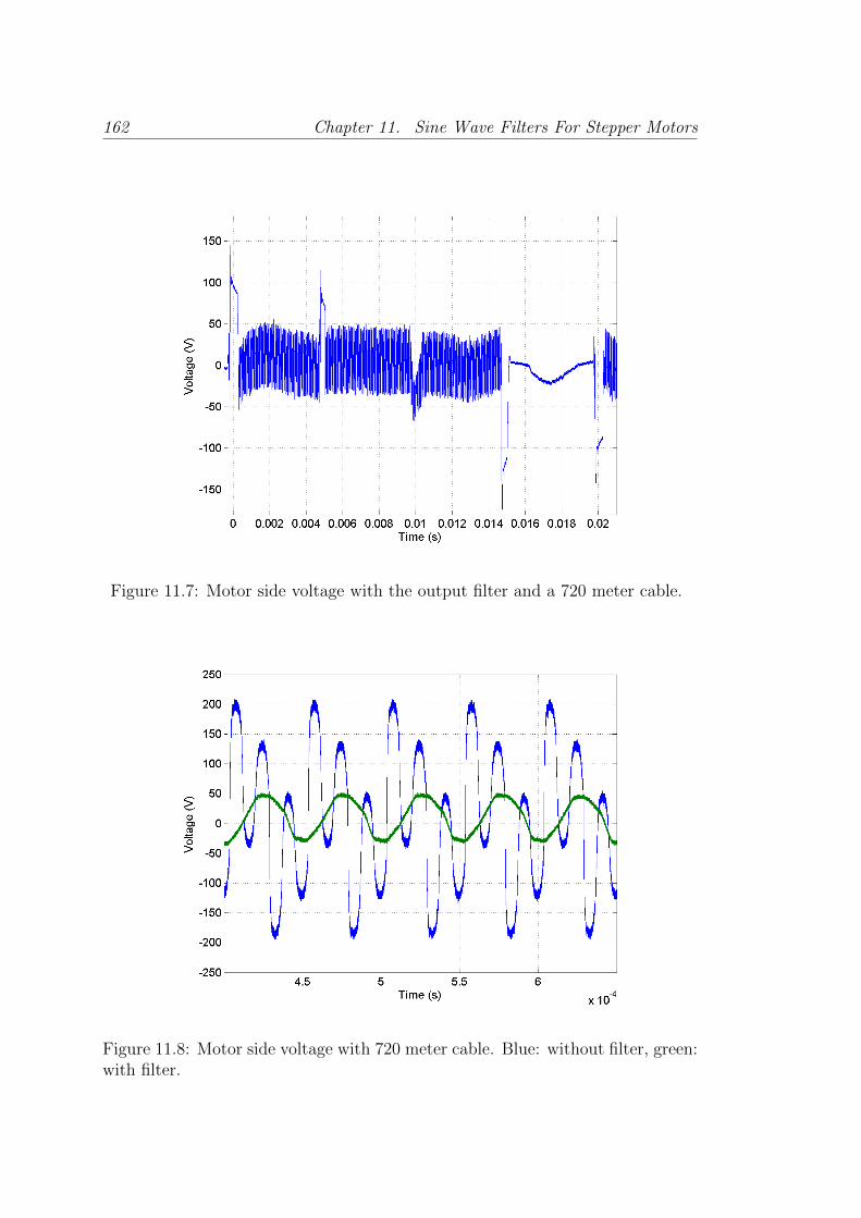
162 Chapter 11. Sine Wave Filters For Stepper Motors
Figure 11.7: Motor side voltage with the output filter and a 720 meter cable.
Figure 11.8: Motor side voltage with 720 meter cable. Blue: without filter, green:with filter.
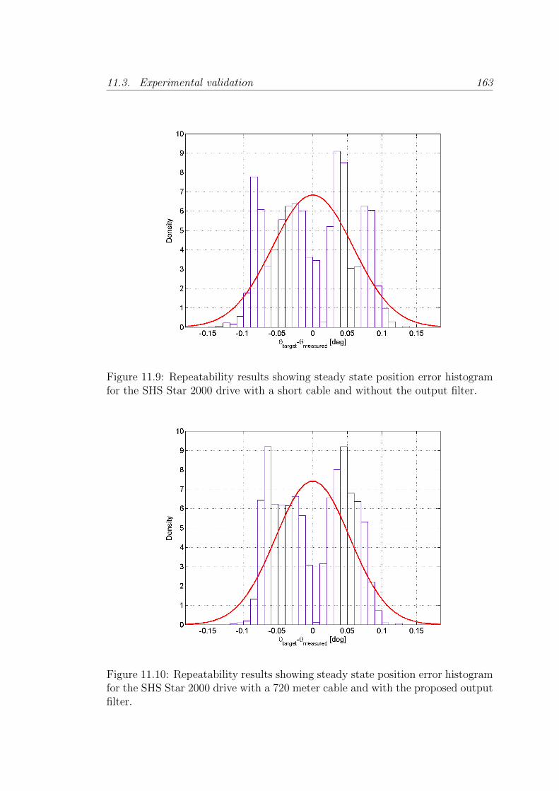
11.3. Experimental validation 163
Figure 11.9: Repeatability results showing steady state position error histogramfor the SHS Star 2000 drive with a short cable and without the output filter.
Figure 11.10: Repeatability results showing steady state position error histogramfor the SHS Star 2000 drive with a 720 meter cable and with the proposed outputfilter.

164 Chapter 11. Sine Wave Filters For Stepper Motors
Figure 11.11: Low frequency spectrum of the EMI emissions for the SHS drive.In green: without output filter and with a short cable, in blue: 720 meter cableand output filter
11.4 Conclusion
An output filter for stepper motor drives has been designed and built. By using it,
both the DM and the CM contributions to the ringing in the drive side current
have been attenuated, allowing a standard commercial drive to work correctly
with a long cable. This is not possible without the filter.
The motor side voltage has been greatly reduced, and thus the motor insula-
tion stress by the high voltage and its derivative, which occurs without the filter,
is in turn greatly reduced. The positioning repeatability has been improved even
compared to the case of the drive working with neither a long cable nor the output
filter. Finally, the EMI emissions have been significantly decreased.
In conclusion the output filter has been demonstrated to be a very effective
and efficient solution for stepper motor drives. By using it, the issues associated
with the use of long cables and chopping drives have been significantly reduced
with a simple solution. The price for this improvement is the introduction of a
few passive components and the power losses associated with them.
Part V
Conclusions

Chapter 12
Conclusions
In this thesis, the modelling and control of hybrid stepper motors in high radiation
areas has been explored in detail. The problematic involved has been analysed,
particular attention has been paid to the effects of using switched converters
when long cables are present, and the difficulties of the limited possibility to use
position sensors.
The first observable effect from the drive point of view, the ringing due to the
transmission line characteristic of the long cable in the drive current, impeded the
normal use of most off-the-shelf drives. The use of estimators has been previously
proposed to obtain the motor currents and closing the current loop on these
estimations.
From this point the problem arising from the difficulty to use position sensors
in the harsh environment present in particle accelerators and the need to de-
tect possible steps lost and mechanical degradation of the collimators led to the
proposal to use sensorless methods for the motor mechanical states. The first
contribution of this thesis is to use the Extended Kalman Filter to es-
timate the Hybrid Stepper Motor position, speed and external torque,
with a long cable connecting motor and drive. It has been proposed, tested
in simulation and validated experimentally on a real LHC collimator.
It has been demonstrated that a trade-off between model complexity and
computational cost must be made to achieve a feasible real-time application. In
this case it implied limiting the model of the system to be used in the Extended
Kalman Filter to the motor without cable, and dealing with the high bandwidth
cable dynamics by using a different faster estimation for the parts not included in
the model used in the Kalman filter, i.e. the cable. Using this estimation scheme,
166
167
it has been demonstrated that the position, speed and load torque estimation
are sufficiently good to allow the degradation of the collimator mechanics to be
monitored and lost steps to be detected.
It was observed though that some mismatch between the expected signals and
the observed ones existed when high phase currents were applied. This mismatch
has been attributed to the saturation of the magnetic components constituting
the magnetic circuit in the motor, specially, as was found in literature, in narrow
parts of the magnetic flux path like the teeth both in stator and rotor. This fact
limits the usability of the proposed method to either use it under a limited current
level, or to include the current level effect in the model, if this were possible in
a real-time estimation application. This lead to the second contribution of
the thesis, the proposal of new extensions of the standard electrical
model of hybrid stepper motors, which could be used in control and
estimation real-time applications.
The electrical motor model has been extended by including position and cur-
rent dependent inductance and permanent magnet flux linkage terms. It has
been shown that the new model offers a better fit with real data acquired from
a running hybrid stepper motor. Finally this model has been implemented in an
EKF running in a DSP based drive, demonstrating the feasibility for real-time
applications and the improvement in the mechanical states estimation, under a
broader range of conditions, i.e. for large current amplitudes.
In addition to the consideration of the possibilities of sensorless estimation,
closed-loop position control has been studied and applied to the LHC collima-
tor motors. The controller structure to apply Field Oriented Control has been
presented as well as the tuning and resolution of practical problems. The im-
provement with closed loop has been shown; obtaining a smoother motion profile
compared to standard open loop. The overshoot and settling time of the position
on each step are significantly reduced.
The third contribution of this thesis is the proposal of a switch
between closed and open loop position control, which, combined with
the developed Field Oriented Control scheme, allows the use of position
sensors without reducing the reliability of the system. This switch is
capable of performing a bumpless transfer between control modes. Moreover, the
angular reference generation has allowed a stepper motor drive to be developed
that with the advantages of the closed loop described, can be directly swapped
168 Chapter 12. Conclusions
with the current stepper drives since the interfaces between the drive and the
other systems are respected.
Using closed-loop position control represents a less aggressive option for the
mechanics, thereby extending their lifespan. Furthermore, it has been shown that
closed loop control can be a direct improvement in several applications at CERN
not only for the LHC collimators, but also for 2 different types of goniometer
used for the crystal collimation project.
In the context of the control of hybrid stepper motors in high radiation areas,
a different approach to deal with the problematic created by the use of switched
drives with long cables has been investigated. Output filters are a solution used
mainly for AC motors in different applications of industry. However, the use of
this type of filter with stepper motors has not been reported at the time of this
work.
An output filter, specifically a Sine Wave Filter, for stepper motor
drives has been designed and built, being the fourth and last contri-
bution of the thesis. Using this filter reduces the differential and common
modes of the voltage applied to the cable from the drive side, resulting in the
attenuation of the aforementioned drive-side current ringing and the motor-side
overvoltage. This allows commercial off-the-shelf drives to work properly with-
out further modification with long cable, as it is the case in the LHC collimators,
whilst enlarging the lifetime of the motor insulation.
In addition, experimental testing has proved that open-loop positioning re-
peatability of a commercial drive with a long cable and the sine wave filter has
improved compared to the same drive with only a short cable. Testing has also
shown that EMI emissions has been greatly reduced compared to the case without
sine wave filter.
12.1 Future work
Several paths are promising to explore from the thesis results:
• Steady state Kalman filter for non-linear application. In this case, due to
the big difference in bandwidths between the fast electrical dynamics and
the slow mechanical ones, which are the ones containing the non-linearity,
using the steady state Kalman filtering could be studied to release the
processor from the heavier filter operations. This would allow for more

12.2. Publications 169
complex control techniques to be applied without the need to increase the
computation power of the processor.
• Future extensions of the work done could be to use the position and speed
estimations for closed-loop control.
• In line with the previous point, an application of the Kalman filter which
could use the encoder or resolver information at a different and even at a
variable rate would be interesting, in order to use the information already
available in some collimator systems, where the resolvers are read at 400 Hz,
and work using this extra information or continue to work with no position
information in the case of a sensor failure.
• If the sensorless control is finally used to close the position loop, the switch
presented in chapter 9 could be triggered when the quality of the estimation,
i.e. the innovation covariance matrix, goes over a certain threshold.
• The sine wave filter has obvious applications and extending the study to
look for different optimizations would be very interesting. A clear useful
goal would be to achieve a physically small filter that could be easily inte-
grated in the current installations with minimum installation complexity.
For this, a good trade-off between common and differential modes attenu-
ation, chopping frequency to use and power dissipation should be found.
12.2 Publications
The achieved results have been published in different journal and conference pub-
lications, listed below.
JCR journal publications:
• A. Masi, M. Butcher, M. Martino, and R. Picatoste. An application of
the extended kalman filter for a sensorless stepper motor drive working
with long cables. IEEE Transactions on Industrial Electronics, 59(11):4217
–4225, nov. 2012. ISSN 0278-0046. doi: 10.1109/TIE.2011.2178213
• A. Masi, M. Butcher, R. Losito, and R. Picatoste. Dsp based smart sen-
sorless stepping motor driver for lhc collimators. Nuclear Science, IEEE
Transactions on, 60(5):3514–3520, Oct 2013. ISSN 0018-9499. doi: 10.
1109/TNS.2013.2267055
170 Chapter 12. Conclusions
• M. Butcher, A. Masi, R. Picatoste, and A. Giustiniani. Hybrid stepper
motor electrical model extensions for use in intelligent drives. Industrial
Electronics, IEEE Transactions on, 61(2):917–929, Feb 2014. ISSN 0278-
0046. doi: 10.1109/TIE.2013.2254097
Conference publications:
• M. Martino, A. Masi, R. Losito, and R. Picatoste Ruilope. Low emission,
self-tunable dsp based stepping motor drive for use with arbitrarily long
cables. In Conference record of the 12th LSS symposium, 2010
• A. Masi, M. Butcher, R. Losito, and R. Picatoste. Dsp based smart sen-
sorless stepping motor driver for lhc collimators. In Real Time Conference
(RT), 2012 18th IEEE-NPSS, pages 1–7, June 2012. doi: 10.1109/RTC.
2012.6418215
• R. Picatoste, M. Butcher, and A. Masi. Sine wave filter for stepper motor
drives working with long cables. In Electrical Machines (ICEM), 2012 XXth
International Conference on, pages 1075–1081, Sept 2012. doi: 10.1109/
ICElMach.2012.6350009

Part VI
Appendices

Appendix A
Analytical formulas for the
extended electrical model
The aim of this Appendix is to provide the reader with the analytical expressions
of the symbolic ones introduced in Section 7.6, considering the position and cur-
rent dependent model. It is worth noticing that for the other proposed models,
the same reasoning could be followed.
In Eqs. 7.32-7.33, the analytical expression of NumA, DenA, NumB, DenB,
are:
NumA =p(aΨe−bΨx2
1 + cΨ) sin(px4 + φΨ)x3
+ 2p(aL2e−bL2
x21 + cL2) sin(2px4 + φL2)x3x1 −Rx1
DenA =(aL2e−bL2
x21 + cL2) cos(2px4 + φL2) + (aL0e
−bL0x2
1 + cL0)
− 2(aL0bL0e−bL0
x21)x2
1 − 2(aL2bL2e−bL2
x21)x2
1 cos(2px4 + φL2)
− 2(aΨbΨe−bΨx2
1)x1 cos(px4 + φΨ)
NumB =− p(aΨe−bΨx2
2 + cΨ) cos(px4 + φΨ)x3
− 2p(aL2e−bL2
x22 + cL2) sin(2px4 + φL2)x3x2 −Rx2
172
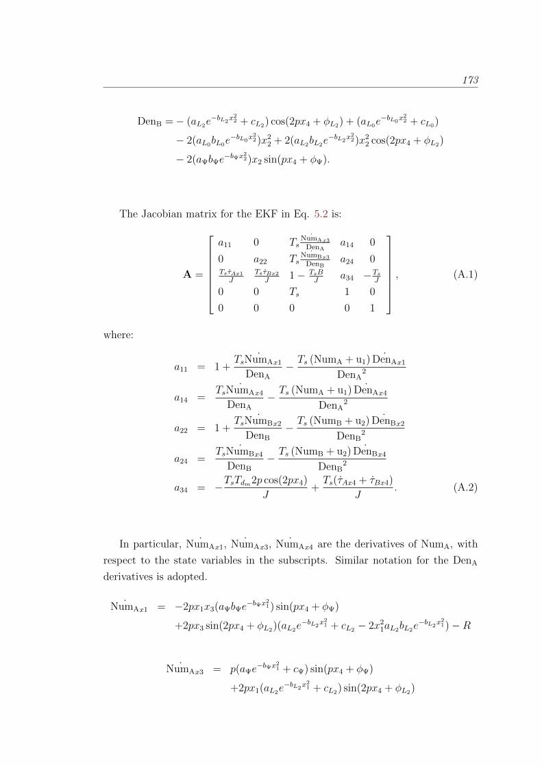
173
DenB =− (aL2e−bL2
x22 + cL2) cos(2px4 + φL2) + (aL0e
−bL0x2
2 + cL0)
− 2(aL0bL0e−bL0
x22)x2
2 + 2(aL2bL2e−bL2
x22)x2
2 cos(2px4 + φL2)
− 2(aΨbΨe−bΨx2
2)x2 sin(px4 + φΨ).
The Jacobian matrix for the EKF in Eq. 5.2 is:
A =
a11 0 Ts˙NumAx3
DenAa14 0
0 a22 Ts˙NumBx3
DenBa24 0
TsτAx1
JTsτBx2
J1− TsB
Ja34 −Ts
J
0 0 Ts 1 0
0 0 0 0 1
, (A.1)
where:
a11 = 1 +Ts ˙NumAx1
DenA
− Ts (NumA + u1) ˙DenAx1
DenA2
a14 =Ts ˙NumAx4
DenA
− Ts (NumA + u1) ˙DenAx4
DenA2
a22 = 1 +Ts ˙NumBx2
DenB
− Ts (NumB + u2) ˙DenBx2
DenB2
a24 =Ts ˙NumBx4
DenB
− Ts (NumB + u2) ˙DenBx4
DenB2
a34 = −TsTdm2p cos(2px4)
J+Ts(τAx4 + τBx4)
J. (A.2)
In particular, ˙NumAx1, ˙NumAx3, ˙NumAx4 are the derivatives of NumA, with
respect to the state variables in the subscripts. Similar notation for the DenA
derivatives is adopted.
˙NumAx1 = −2px1x3(aΨbΨe−bΨx2
1) sin(px4 + φΨ)
+2px3 sin(2px4 + φL2)(aL2e−bL2
x21 + cL2 − 2x2
1aL2bL2e−bL2
x21)−R
˙NumAx3 = p(aΨe−bΨx2
1 + cΨ) sin(px4 + φΨ)
+2px1(aL2e−bL2
x21 + cL2) sin(2px4 + φL2)
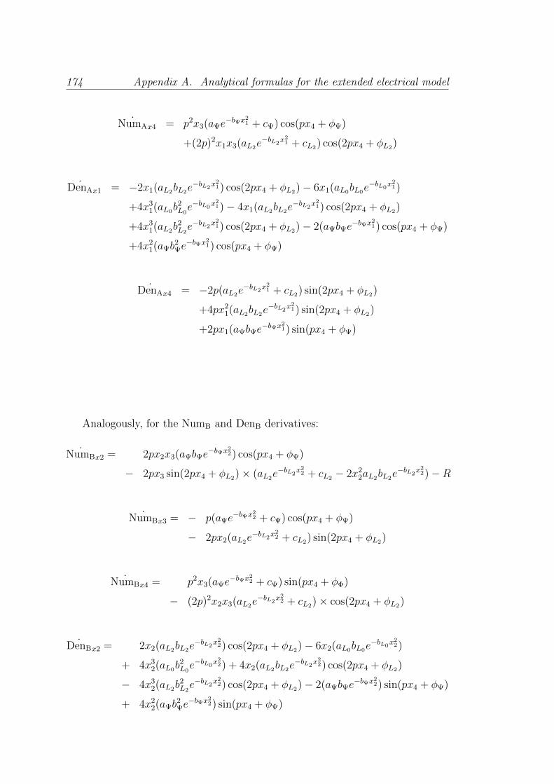
174 Appendix A. Analytical formulas for the extended electrical model
˙NumAx4 = p2x3(aΨe−bΨx2
1 + cΨ) cos(px4 + φΨ)
+(2p)2x1x3(aL2e−bL2
x21 + cL2) cos(2px4 + φL2)
˙DenAx1 = −2x1(aL2bL2e−bL2
x21) cos(2px4 + φL2)− 6x1(aL0bL0e
−bL0x2
1)
+4x31(aL0b
2L0e−bL0
x21)− 4x1(aL2bL2e
−bL2x2
1) cos(2px4 + φL2)
+4x31(aL2b
2L2e−bL2
x21) cos(2px4 + φL2)− 2(aΨbΨe
−bΨx21) cos(px4 + φΨ)
+4x21(aΨb
2Ψe−bΨx2
1) cos(px4 + φΨ)
˙DenAx4 = −2p(aL2e−bL2
x21 + cL2) sin(2px4 + φL2)
+4px21(aL2bL2e
−bL2x2
1) sin(2px4 + φL2)
+2px1(aΨbΨe−bΨx2
1) sin(px4 + φΨ)
Analogously, for the NumB and DenB derivatives:
˙NumBx2 = 2px2x3(aΨbΨe−bΨx2
2) cos(px4 + φΨ)
− 2px3 sin(2px4 + φL2)× (aL2e−bL2
x22 + cL2 − 2x2
2aL2bL2e−bL2
x22)−R
˙NumBx3 = − p(aΨe−bΨx2
2 + cΨ) cos(px4 + φΨ)
− 2px2(aL2e−bL2
x22 + cL2) sin(2px4 + φL2)
˙NumBx4 = p2x3(aΨe−bΨx2
2 + cΨ) sin(px4 + φΦ)
− (2p)2x2x3(aL2e−bL2
x22 + cL2)× cos(2px4 + φL2)
˙DenBx2 = 2x2(aL2bL2e−bL2
x22) cos(2px4 + φL2)− 6x2(aL0bL0e
−bL0x2
2)
+ 4x32(aL0b
2L0e−bL0
x22) + 4x2(aL2bL2e
−bL2x2
2) cos(2px4 + φL2)
− 4x32(aL2b
2L2e−bL2
x22) cos(2px4 + φL2)− 2(aΨbΨe
−bΨx22) sin(px4 + φΨ)
+ 4x22(aΨb
2Ψe−bΨx2
2) sin(px4 + φΨ)
175
˙DenBx4 = 2p(aL2e−bL2
x22 + cL2) sin(2px4 + φL2)
− 4px22(aL2bL2e
−bL2x2
2) sin(2px4 + φL2)
− 2px2(aΨbΨe−bΨx2
2) cos(px4 + φΨ).
Moreover, τAx1 , τAx4 , are the derivatives of τA, with respect to the state variables
in the subscripts.
τAx1 = − (2p)x1
[cL2 +
aL2
ebL2x2
1
]sin(2px4 + φL2)
− (p)
[cΨ +
aΨ
ebψx21
]sin(px4 + φΨ)
τAx4 = − (2p)2
[cL2
x21
2− aL2
2bL2ebL2
x21
+aL2
2bL2
]× cos(2px4 + φL2)
− (p)2
[cΨx1 +
aΨ
√πerf(
√bΨx1)
2√bΨ
]cos(px4 + φΨ).
Similar notation for the τB derivatives is held:
τBx2 = (2p)x2
[cL2 −
aL2
ebL2x2
2
]sin(2px4 + φL2)
+ (p)
[cΨ +
aΨ
ebΨx22
]cos(px4 + φΨ)
τBx4 = (2p)2
[cL2
x22
2− aL2
2bL2ebL2
x22
+aL2
2bL2
]× cos(2px4 + φL2)
− (p)2
[cΨx2 +
aΨ
√πerf(
√bΨx2)
2√bΨ
]× sin(px4 + φΨ).

Appendix B
CERN Field Oriented Control
Motor Applications
B.1 CINEL Stepper motor based Goniometer
A different approach for the collimation systems is being researched and tested at
CERN. This approach, known as crystal collimation, intends to use bent silicon
crystals as primary collimators to direct the beam halo onto a secondary absorber,
instead of directly stopping the desired particles. The theoretical details and
working principle of this project are outside the scope of this work, but can be
found in its original proposal [76] and later publications [75].
The aforementioned crystals have to be positioned next to the beam with
an angular accuracy of 1 micro-radian [74]. A prototype of a goniometer was
proposed and built in collaboration with the Italian company CINEL with the
goal of achieving such a specification.
A schematic view of the working principle is shown in Fig. B.1. The stepper
motors M1 and M2 move the platform where the crystal is mounted in order to
align it with the beam line. The motor M1 alone displaces a platform connected
through a lever arm to the crystal platform. The latter is fixed to the lever arm
and rotates with it as indicated in the figure, allowing the crystal to be positioned
at the desired angle.
In Figs. B.2 and B.3 a picture of the prototype and the 3D model are shown
respectively.
This prototype has been tested intensively with standard stepping drives, and
even though the positioning accuracy and resolution were fulfilled, the strong
176
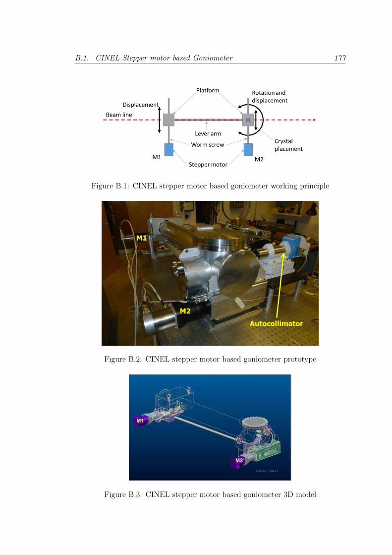
B.1. CINEL Stepper motor based Goniometer 177
Figure B.1: CINEL stepper motor based goniometer working principle
Figure B.2: CINEL stepper motor based goniometer prototype
Figure B.3: CINEL stepper motor based goniometer 3D model
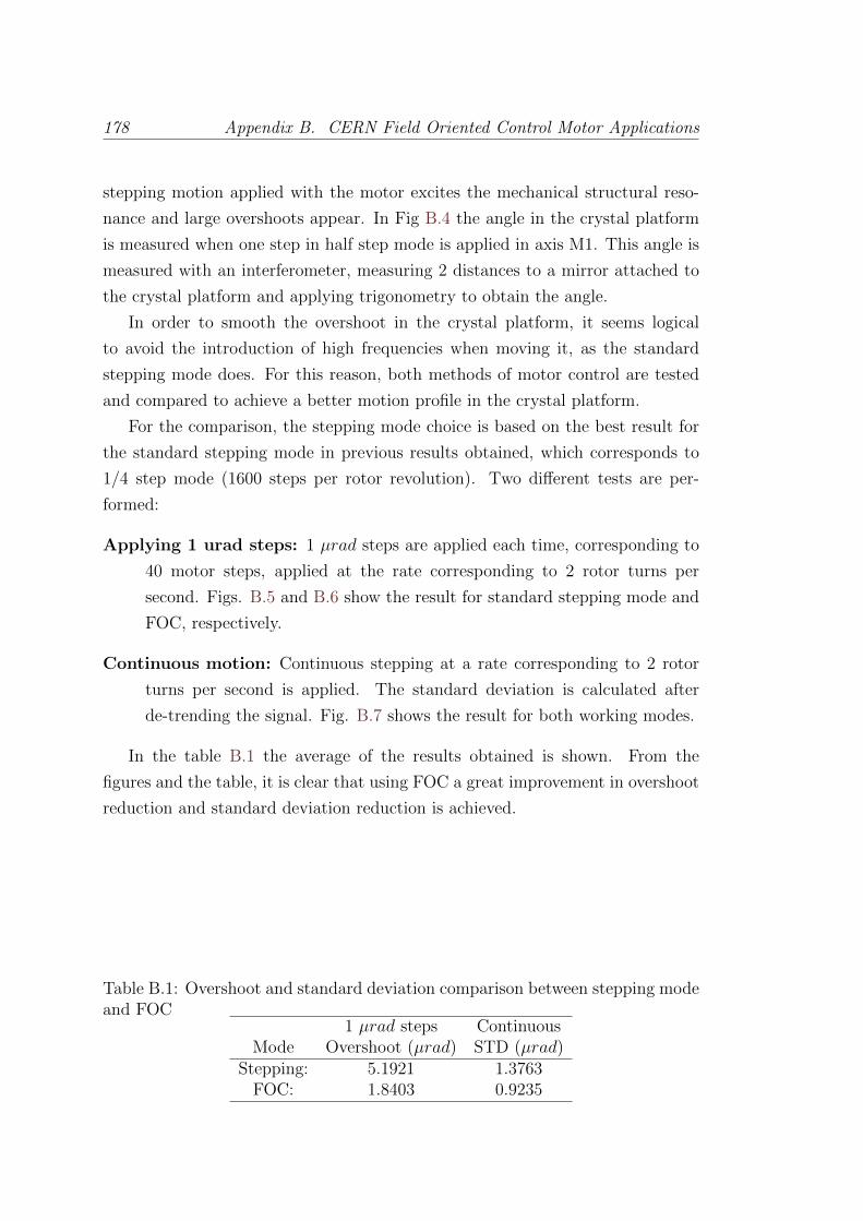
178 Appendix B. CERN Field Oriented Control Motor Applications
stepping motion applied with the motor excites the mechanical structural reso-
nance and large overshoots appear. In Fig B.4 the angle in the crystal platform
is measured when one step in half step mode is applied in axis M1. This angle is
measured with an interferometer, measuring 2 distances to a mirror attached to
the crystal platform and applying trigonometry to obtain the angle.
In order to smooth the overshoot in the crystal platform, it seems logical
to avoid the introduction of high frequencies when moving it, as the standard
stepping mode does. For this reason, both methods of motor control are tested
and compared to achieve a better motion profile in the crystal platform.
For the comparison, the stepping mode choice is based on the best result for
the standard stepping mode in previous results obtained, which corresponds to
1/4 step mode (1600 steps per rotor revolution). Two different tests are per-
formed:
Applying 1 urad steps: 1 µrad steps are applied each time, corresponding to
40 motor steps, applied at the rate corresponding to 2 rotor turns per
second. Figs. B.5 and B.6 show the result for standard stepping mode and
FOC, respectively.
Continuous motion: Continuous stepping at a rate corresponding to 2 rotor
turns per second is applied. The standard deviation is calculated after
de-trending the signal. Fig. B.7 shows the result for both working modes.
In the table B.1 the average of the results obtained is shown. From the
figures and the table, it is clear that using FOC a great improvement in overshoot
reduction and standard deviation reduction is achieved.
Table B.1: Overshoot and standard deviation comparison between stepping modeand FOC
1 µrad steps ContinuousMode Overshoot (µrad) STD (µrad)
Stepping: 5.1921 1.3763FOC: 1.8403 0.9235
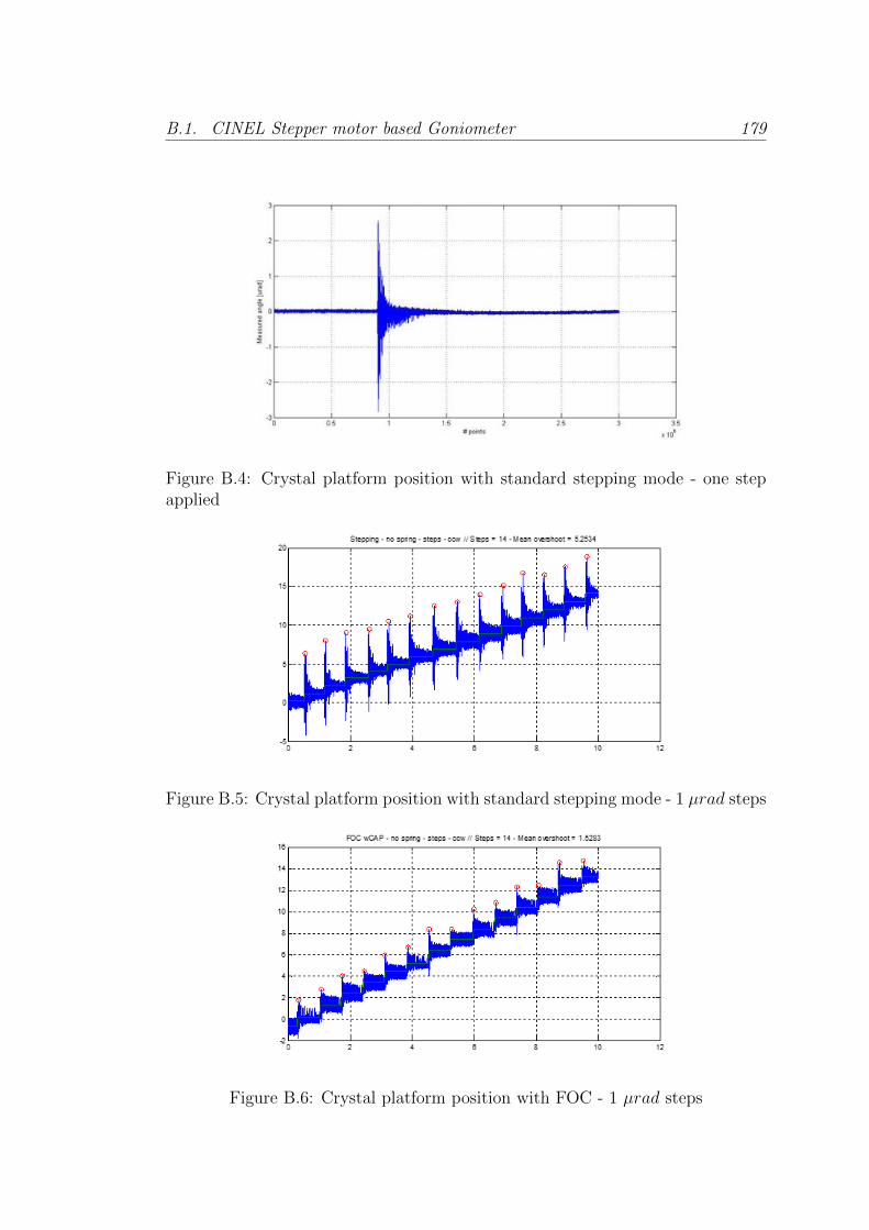
B.1. CINEL Stepper motor based Goniometer 179
Figure B.4: Crystal platform position with standard stepping mode - one stepapplied
Figure B.5: Crystal platform position with standard stepping mode - 1 µrad steps
Figure B.6: Crystal platform position with FOC - 1 µrad steps
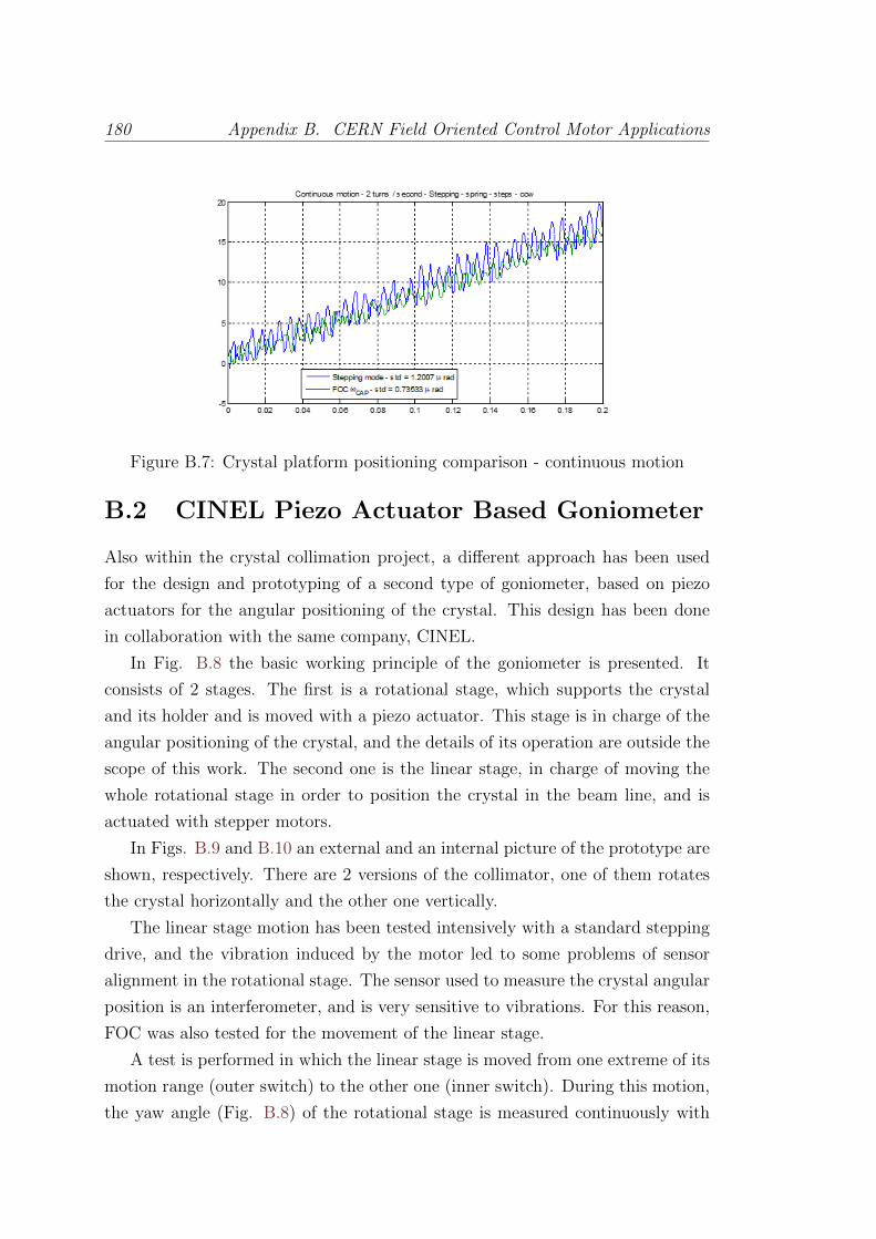
180 Appendix B. CERN Field Oriented Control Motor Applications
Figure B.7: Crystal platform positioning comparison - continuous motion
B.2 CINEL Piezo Actuator Based Goniometer
Also within the crystal collimation project, a different approach has been used
for the design and prototyping of a second type of goniometer, based on piezo
actuators for the angular positioning of the crystal. This design has been done
in collaboration with the same company, CINEL.
In Fig. B.8 the basic working principle of the goniometer is presented. It
consists of 2 stages. The first is a rotational stage, which supports the crystal
and its holder and is moved with a piezo actuator. This stage is in charge of the
angular positioning of the crystal, and the details of its operation are outside the
scope of this work. The second one is the linear stage, in charge of moving the
whole rotational stage in order to position the crystal in the beam line, and is
actuated with stepper motors.
In Figs. B.9 and B.10 an external and an internal picture of the prototype are
shown, respectively. There are 2 versions of the collimator, one of them rotates
the crystal horizontally and the other one vertically.
The linear stage motion has been tested intensively with a standard stepping
drive, and the vibration induced by the motor led to some problems of sensor
alignment in the rotational stage. The sensor used to measure the crystal angular
position is an interferometer, and is very sensitive to vibrations. For this reason,
FOC was also tested for the movement of the linear stage.
A test is performed in which the linear stage is moved from one extreme of its
motion range (outer switch) to the other one (inner switch). During this motion,
the yaw angle (Fig. B.8) of the rotational stage is measured continuously with
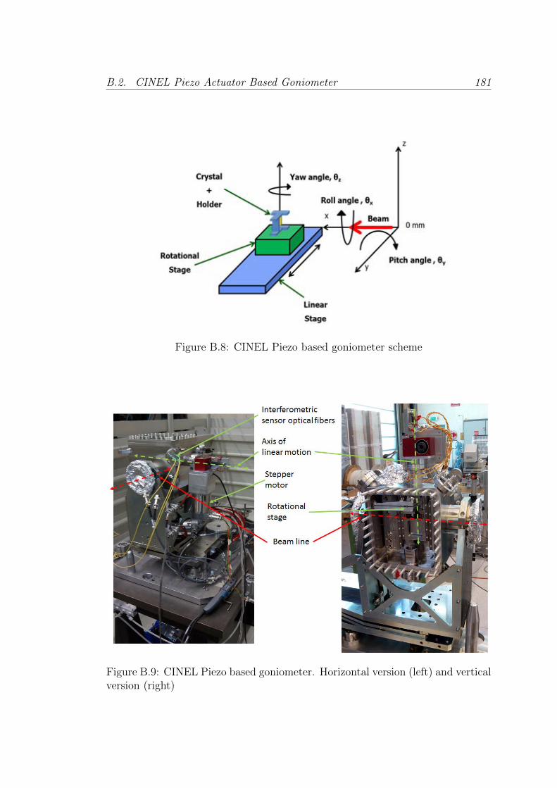
B.2. CINEL Piezo Actuator Based Goniometer 181
Figure B.8: CINEL Piezo based goniometer scheme
Figure B.9: CINEL Piezo based goniometer. Horizontal version (left) and verticalversion (right)

182 Appendix B. CERN Field Oriented Control Motor Applications
Figure B.10: CINEL Piezo based goniometer internal picture
the interferometer. This test has two parts, one where the rotational stage is not
actuated by the piezo, and other one where the rotational stage is in closed loop
holding its position.
In Fig. B.11 the results for the test performed with the rotational stage in
open loop are shown. The measured yaw angle show that the oscillations along
the linear range are significantly bigger in the stepper working mode than using
FOC. The net increase in the angle is due to the mirror support deformation
during the linear displacement.
In Fig. B.12 the results for the test performed with the rotational stage in
closed loop are shown. Closing the loop in the rotational stage means that the
piezo actuator follows the reference yaw angle given. For this test this reference
is be zero, i.e. to hold the position during the movement. As result, the net
increase of the yaw angle is zero in this occasion, but the oscillations during the
movement are again significantly smaller in the FOC case. In table B.2 the result
of this test is summarized quantitatively.
Even though improving the support of the interferometric sensor components
Table B.2: Standard deviation of the parasitic yaw in the rotational stage inclosed loop test
InterferometerMode STD (µrad)
Stepping: 10.7805FOC: 4.4462

B.2. CINEL Piezo Actuator Based Goniometer 183
Figure B.11: CINEL Piezo based goniometer, rotational stage in open loop, fulllinear range motion parasitic yaw in standard stepping mode (left) and FOC(right)
Figure B.12: CINEL Piezo based goniometer, rotational stage in closed loop, fulllinear range motion parasitic yaw comparison in standard stepping mode (left)and FOC (right)

184 Appendix B. CERN Field Oriented Control Motor Applications
in the rotational stage has improved the situation regarding the sensor misalign-
ment provoked by the vibrations, using FOC seems a better option to avoid
further problems with this type of highly sensitive sensor.
Bibliography
[1] P.P. Acarnley. Stepping motors: a guide to theory and practice. Number 63.
Iet, 2002.
[2] P.P. Acarnley and J.F. Watson. Review of position-sensorless operation of
brushless permanent-magnet machines. IEEE Transactions on Industrial
Electronics, 53(2), 2006.
[3] F. Auger and M. Hilairet. Industrial applications of the kalman filter: A
review. IEEE Transactions on Industrial Electronics, PP(99):1, 2013. ISSN
0278-0046. doi: 10.1109/TIE.2012.2236994.
[4] L.D. Avendano-Valencia, L.E. Avendano, J.M. Ferrero, and G. Castellanos-
Dominguez. Improvement of an extended kalman filter power line interfer-
ence suppressor for ecg signals. In Computers in Cardiology, 2007, pages 553
–556, sep. 2007. doi: 10.1109/CIC.2007.4745545.
[5] M. Barut, S. Bogosyan, and M. Gokasan. Speed-sensorless estimation for
induction motors using extended kalman filters. IEEE Transactions on In-
dustrial Electronics, 54(1):272–280, 2007.
[6] M. Bendjedia, Y. Ait-Amirat, B. Walther, and A. Berthon. Sensorless control
of hybrid stepper motor. In 2007 European Conference on Power Electronics
and Applications, pages 1–10. IEEE, 2007.
[7] M. Bendjedia, Y. Ait-Amirat, B. Walther, and A. Berthon. Position control
of a sensorless stepper motor. IEEE Transactions on Power Electronics, 27
(2):578587, 2012.
[8] M. Bendjedia, A. Khlaief, and M. Boussak. Sensorless speed control of
outrunner pmsm drive connected to long cable for flying remote operative
vehicle. pages 2252–2258, Sept 2012. doi: 10.1109/ICElMach.2012.6350195.
185
186 Bibliography
[9] F. Betin, D. Pinchon, and G.-A Capolino. Fuzzy logic applied to speed
control of a stepping motor drive. Industrial Electronics, IEEE Transactions
on, 47(3):610–622, Jun 2000. ISSN 0278-0046. doi: 10.1109/41.847902.
[10] J. Bocker and S. Mathapati. State of the art of induction motor control.
In Electric Machines Drives Conference, 2007. IEMDC ’07. IEEE Interna-
tional, volume 2, pages 1459–1464, May 2007. doi: 10.1109/IEMDC.2007.
383643.
[11] L. Bodizs, B. Srinivasan, and D. Bonvin. Preferential estimation via tuning
of the kalman filter. In DYCOPS 7, page 108, 2004.
[12] S. Bolognani, R. Oboe, and M. Zigliotto. Sensorless full-digital PMSM drive
with EKF estimation of speed and rotor position. IEEE Transactions on
Industrial Electronics, 46(1):184–191, 1999.
[13] F. Briz and M.W. Degner. Rotor position estimation. IEEE Industrial
Electronics Magazine, 5(2):24 –36, June 2011. ISSN 1932-4529. doi: 10.
1109/MIE.2011.941118.
[14] R. G. Brown and P. Y. C Hwang. Introduction to Random Signals and
Applied Kalman Filtering. John Wiley & Sons, 1985.
[15] M. Butcher, A. Masi, R. Picatoste, and A. Giustiniani. Hybrid stepper
motor electrical model extensions for use in intelligent drives. Industrial
Electronics, IEEE Transactions on, 61(2):917–929, Feb 2014. ISSN 0278-
0046. doi: 10.1109/TIE.2013.2254097.
[16] Mark Butcher, Alessandro Masi, Michele Martino, and Andrea Tacchetti.
Implementation and tuning of the extended kalman filter for a sensorless
drive working with arbitrary stepper motors and cable lengths. In XXth
International Conference on Electrical Machines (ICEM), pages 2216 –2222,
sept. 2012. doi: 10.1109/ICElMach.2012.6350190.
[17] D. Casadei, F. Profumo, G. Serra, and A Tani. Foc and dtc: two vi-
able schemes for induction motors torque control. Power Electronics,
IEEE Transactions on, 17(5):779–787, Sep 2002. ISSN 0885-8993. doi:
10.1109/TPEL.2002.802183.
Bibliography 187
[18] W.D. Chen, K.L. Yung, and K.W. Cheng. A learning scheme for low-
speed precision tracking control of hybrid stepping motors. Mechatronics,
IEEE/ASME Transactions on, 11(3):362–365, June 2006. ISSN 1083-4435.
doi: 10.1109/TMECH.2006.875574.
[19] G. Conte. Control optimization of the LHC stepping motor drivers. Master’s
thesis, Universita degli Studi di Napoli Federico II, 2006.
[20] A.C.S. de Lima, R.M. Stephan, A. Pedroso, and J. Mourente. Analysis of a
long distance drive for an induction motor. 2:867–872 vol.2, Jun 1996. doi:
10.1109/ISIE.1996.551057.
[21] M. Depenbrock. Direct self-control (dsc) of inverter-fed induction machine.
Power Electronics, IEEE Transactions on, 3(4):420–429, Oct 1988. ISSN
0885-8993. doi: 10.1109/63.17963.
[22] R. Devasahayam, V.T.S. Achary, M. H. Ravichandran, S. Simon, P. Mu-
ralikrishna, C. C. Joseph, and P. M. Varghese. Performance enhancement
of a 720-step stepper motor for solar array drive of indian remote sensing
satellites to achieve low power micro-stepping. In Power Electronics and
Drive Systems, 2003. PEDS 2003. The Fifth International Conference on,
volume 1, pages 264–268 Vol.1, Nov 2003. doi: 10.1109/PEDS.2003.1282784.
[23] H. Durrant-Whyte. Introduction to Estimation and the Kalman Filter. Aus-
tralian Centre for Field Robotics, 2001.
[24] Timothy A Ferris, Stephen M Fortescue, and Gaston Palombo. High per-
formance incremental motion system using a closed loop stepping motor,
May 27 1986. US Patent 4,591,774.
[25] P.T. Finlayson. Output filters for PWM drives with induction motors. Indus-
try Applications Magazine, IEEE, 4(1):46 –52, jan/feb 1998. ISSN 1077-2618.
doi: 10.1109/2943.644886.
[26] A. E. Fitzgerald, C. Jr. Kingsley, and S. D. Umans. Electric Machinery.
McGraw-Hill, 2003.
[27] Hamed Shisheh Foroush. Angle estimation in a pwm stepper motor driver
by kalman filtering. Master’s thesis, cole polytechnique fdrale de Lausanne
(EPFL), 2010.
188 Bibliography
[28] Gene F Franklin, Michael L Workman, and Dave Powell. Digital control of
dynamic systems. Addison-Wesley Longman Publishing Co., Inc., 1997.
[29] Xavier del Toro Garcia, Branislav Zigmund, Angela A Terlizzi, Rastislav
Pavlanin, and Ligui Salvatore. Comparison between foc and dtc strategies
for permanent magnet synchronous motors. Advances in Electrical and Elec-
tronic Engineering, 5(1-2):76–81, 2011.
[30] M.S. Grewal and A.P. Andrews. Kalman filtering: theory and practice using
MATLAB. Wiley-IEEE Press, 2008.
[31] S. Hang. Understanding extended kalman filter. Technical report, Faculty of
Engineering and Information Technology, University of Technology Sydney,
2010.
[32] N. Hanigovszki. EMC output filters for adjustable speed drives. PhD thesis,
2005.
[33] S.Y.R. Hui, J.G. Zhu, and V.S. Ramsden. A generalized dynamic circuit
model of magnetic cores for low- and high-frequency applications. ii. circuit
model formulation and implementation. Power Electronics, IEEE Transac-
tions on, 11(2):251–259, Mar 1996. ISSN 0885-8993. doi: 10.1109/63.486173.
[34] Seong Gu Kang and D.K. Lieu. Torque analysis of combined 2d fem and
lumped parameter method for a hybrid stepping motor. In Electric Machines
and Drives, 2005 IEEE International Conference on, pages 1199 –1203, may
2005. doi: 10.1109/IEMDC.2005.195874.
[35] H Kellermann, P Hildinger, G Brandenburg, and J Heinzl. Field oriented
position control of a hybrid stepper motor. In Proc. of the EPE Conference,
volume 3, pages 908–913, 1995.
[36] T. Kenjo and A. Sugawara. Stepping motors and their microprocessor con-
trols. Clarendon Press Oxford, 1994.
[37] R.J. Kerkman, D. Leggate, and G.L. Skibinski. Interaction of drive modu-
lation and cable parameters on ac motor transients. Industry Applications,
IEEE Transactions on, 33(3):722–731, May 1997. ISSN 0093-9994. doi:
10.1109/28.585863.
Bibliography 189
[38] T. Kim, H.W. Lee, and M. Ehsani. Position sensorless brushless dc mo-
tor/generator drives: review and future trends. Electric Power Applications,
IET, 1(4):557–564, 2007.
[39] W. Kim, D. Shin, and C.C. Chung. Microstepping using a disturbance
observer and a variable structure controller for permanent-magnet stepper
motors. IEEE Transactions on Industrial Electronics, 60(7):2689–2699, July
2013. ISSN 0278-0046. doi: 10.1109/TIE.2012.2198033.
[40] T. Kosaka and N. Matsui. Simple nonlinear magnetic analysis for three-phase
hybrid stepping motors. In Conference Record of the 2000 IEEE Industry
Applications Conference, volume 1, pages 126–131. IEEE, 2000.
[41] C. Kuert, M. Jufer, and Y. Perriard. New method for dynamic modeling of
hybrid stepping motors. In 37th IAS Annual Meeting. Conference Record of
the Industry Applications Conference, volume 1, pages 6–12. IEEE, 2002.
[42] M.D. Laan. Signal Sampling Techniques for Data Acquisition in Process
Control. PhD thesis, University of Groningen, 1995.
[43] I.D. Landau and G. Zito. Digital control systems: design, identification and
implementation. Springer Verlag, 2006.
[44] Quy Ngoc Le and Jae-Wook Jeon. Neural-network-based low-speed-damping
controller for stepper motor with an fpga. Industrial Electronics, IEEE
Transactions on, 57(9):3167–3180, Sept 2010. ISSN 0278-0046. doi:
10.1109/TIE.2009.2037650.
[45] C.A. Lightcap and S.A. Banks. An extended kalman filter for real-time esti-
mation and control of a rigid-link flexible-joint manipulator. IEEE Transac-
tions on Control Systems Technology, 18(1):91 –103, jan. 2010. ISSN 1063-
6536. doi: 10.1109/TCST.2009.2014959.
[46] Ki-Chae Lim, Jung-Pyo Hong, and Gyu-Tak Kim. Characteristic analysis
of 5-phase hybrid stepping motor considering the saturation effect. IEEE
Transactions on Magnetics, 37(5):3518 –3521, sep 2001. ISSN 0018-9464.
doi: 10.1109/20.952651.
190 Bibliography
[47] S. Lin and E.S. Kuh. Transient simulation of lossy interconnects based on
the recursive convolution formulation. IEEE Transactions on Circuits and
Systems. 1, Fundamental theory and applications, 39(11):879–892, 1992.
[48] Weijie Lin and Zhuo Zheng. Simulation and experiment of sensorless direct
torque control of hybrid stepping motor based on dsp. In Mechatronics
and Automation, Proceedings of the 2006 IEEE International Conference
on, pages 2133–2138, June 2006. doi: 10.1109/ICMA.2006.257623.
[49] Roland Longchamp. Commande Numrique De Systmes Dynamiques - Cours
D’automatique. PPUR Presses polytechniques, 2006.
[50] M. Martino, A. Masi, R. Losito, and R. Picatoste Ruilope. Low emission,
self-tunable dsp based stepping motor drive for use with arbitrarily long
cables. In Conference record of the 12th LSS symposium, 2010.
[51] A. Masi and R. Losito. Lhc collimators low level control system. IEEE
Transactions on Nuclear Science, 55(1):333–340, Feb. 2008. ISSN 0018-9499.
doi: 10.1109/TNS.2007.914206.
[52] A. Masi, G. Conte, R. Losito, and M. Martino. Dsp-based stepping motor
drivers for the lhc collimators. IEEE Transactions on Nuclear Science, 55(1
Part 1):341–348, 2008.
[53] A. Masi, G. Conte, R. Losito, and M. Martino. Driving the LHC collimators
stepping motors over 1 km with high accuracy avoiding EMI effects. In
Proceedings of IPAC2011, San Sebastian, Spain, 2011.
[54] A. Masi, M. Butcher, R. Losito, and R. Picatoste. Dsp based smart sen-
sorless stepping motor driver for lhc collimators. In Real Time Conference
(RT), 2012 18th IEEE-NPSS, pages 1–7, June 2012. doi: 10.1109/RTC.
2012.6418215.
[55] A. Masi, M. Butcher, M. Martino, and R. Picatoste. An application of the
extended kalman filter for a sensorless stepper motor drive working with long
cables. IEEE Transactions on Industrial Electronics, 59(11):4217 –4225, nov.
2012. ISSN 0278-0046. doi: 10.1109/TIE.2011.2178213.
[56] A. Masi, M. Butcher, R. Losito, and R. Picatoste. Dsp based smart
sensorless stepping motor driver for lhc collimators. Nuclear Science,
Bibliography 191
IEEE Transactions on, 60(5):3514–3520, Oct 2013. ISSN 0018-9499. doi:
10.1109/TNS.2013.2267055.
[57] N. Matsui, M. Nakamura, and T. Kosaka. Instantaneous torque analysis of
hybrid stepping motor. IEEE Transactions on Industry Applications, 32(5):
1176 –1182, sep/oct 1996. ISSN 0093-9994. doi: 10.1109/28.536880.
[58] P. Maybeck. Stochastic Models, Estimation, and Control. Vol. 1. Academic
Press, 1979.
[59] Giovanni Miano and Antonio Maffucci. Transmission Lines and Lumped
Circuits. Academic Press, 2001.
[60] A.F. Moreira, T.A. Lipo, G. Venkataramanan, and S. Bernet. High-frequency
modeling for cable and induction motor overvoltage studies in long cable
drives. Industry Applications, IEEE Transactions on, 38(5):1297–1306, Sep
2002. ISSN 0093-9994. doi: 10.1109/TIA.2002.802920.
[61] M.J. Nave. On modeling the common mode inductor. In Electromagnetic
Compatibility, 1991. Symposium Record., IEEE 1991 International Sympo-
sium on, pages 452 –457, aug 1991. doi: 10.1109/ISEMC.1991.148275.
[62] C. Obermeier, H. Kellermann, G. Brandenburg, and J. Heinzl. Sensorless
field oriented speed control of a hybrid stepper motor using an extended
kalman filter. In 7th European Conference on Power Electronics and Appli-
cations (EPE’97), 1997.
[63] R.H. Park. Two-reaction theory of synchronous machines generalized method
of analysis-part i. American Institute of Electrical Engineers, Transactions
of the, 48(3):716–727, July 1929. ISSN 0096-3860. doi: 10.1109/T-AIEE.
1929.5055275.
[64] Clayton R. Paul. Introduction to Electromagnetic Compatibility. John Wiley
& Sons, 2006.
[65] Youbin Peng, D. Vrancic, and R. Hanus. Anti-windup, bumpless, and con-
ditioned transfer techniques for pid controllers. Control Systems, IEEE, 16
(4):48–57, Aug 1996. ISSN 1066-033X. doi: 10.1109/37.526915.
192 Bibliography
[66] J. Persson and Y. Perriard. An optimized extended kalman filter algorithm
for hybrid stepper motors. In The 29th Annual Conference of the IEEE
Industrial Electronics Society, IECON’03., volume 1, pages 297–300, 2003.
[67] Jan Persson. Innovative Standstill Position Detection Combined With Sen-
sorless Control of Synchronous Motors. PhD thesis, cole Polytechnique
Fdrale de Lausanne, 2005.
[68] R. Petrella, M. Tursini, L. Peretti, and M. Zigliotto. Speed measurement al-
gorithms for low-resolution incremental encoder equipped drives: a compar-
ative analysis. In Electrical Machines and Power Electronics, 2007. ACEMP
’07. International Aegean Conference on, pages 780–787, Sept 2007. doi:
10.1109/ACEMP.2007.4510607.
[69] R. Picatoste. Development of a stepper motor drive and kalman filter applica-
tion for the lhc collimation system. Master’s thesis, Universidad Politecnica
de Madrid, 2010.
[70] R. Picatoste, M. Butcher, and A. Masi. Sine wave filter for stepper motor
drives working with long cables. In Electrical Machines (ICEM), 2012 XXth
International Conference on, pages 1075–1081, Sept 2012. doi: 10.1109/
ICElMach.2012.6350009.
[71] P. Rocco, G. Gruosso, and G. Magnani. Mechatronic model of oscillations in
hybrid stepper motors. In 2010 IEEE/ASME International Conference on
Advanced Intelligent Mechatronics, pages 726 –731, july 2010. doi: 10.1109/
AIM.2010.5695852.
[72] A Rubaai, M.J. Castro-Sitiriche, M. Garuba, and L. Burge. Implementation
of artificial neural network-based tracking controller for high-performance
stepper motor drives. Industrial Electronics, IEEE Transactions on, 54(1):
218–227, Feb 2007. ISSN 0278-0046. doi: 10.1109/TIE.2006.888785.
[73] N. Salvatore, A. Caponio, F. Neri, S. Stasi, and G.L. Cascella. Optimization
of delayed-state kalman-filter-based algorithm via differential evolution for
sensorless control of induction motors. IEEE Transactions on Industrial
Electronics, 57(1):385–394, 2010. ISSN 0278-0046.
[74] Walter Scandale. Ua9 report for 2013. Technical report, CERN, 2013.
Bibliography 193
[75] Walter Scandale. The ua9 experiment on crystal-assisted collimation at the
cern-super proton synchrotron: Tutorial 48. IEEE Instrumentation & Mea-
surement Magazine, 1094(6969/14), 2014.
[76] Walter Scandale and Michela Prest. Proposal of the crystal experiment.
Technical report, CERN, 2008.
[77] T. Schuhmann, W. Hofmann, and R. Werner. Improving operational per-
formance of active magnetic bearings using kalman filter and state feedback
control. IEEE Transactions on Industrial Electronics, 59(2):821 –829, Feb.
2012. ISSN 0278-0046. doi: 10.1109/TIE.2011.2161056.
[78] K.L. Shi, T.F. Chan, Y.K. Wong, and S.L. Ho. Speed estimation of an
induction motor drive using an optimized extended kalman filter. IEEE
Transactions on Industrial Electronics, 49(1):124–133, 2002.
[79] D. Simon. Optimal state estimation: Kalman, H∞ and nonlinear approaches.
John Wiley and Sons, 2006.
[80] S.P. Singh, J.H. Burry, and B. Watson. Approximation theory and spline
functions. D Reidel Pub Co, 1984.
[81] G.L. Skibinski, R.J. Kerkman, and D. Schlegel. EMI emissions of mod-
ern PWM AC drives. Industry Applications Magazine, IEEE, 5(6):47 –80,
nov/dec 1999. ISSN 1077-2618. doi: 10.1109/2943.798337.
[82] Y. Sozer, D.A. Torrey, and S. Reva. New inverter output filter topology for
PWM motor drives. Power Electronics, IEEE Transactions on, 15(6):1007
–1017, nov 2000. ISSN 0885-8993. doi: 10.1109/63.892815.
[83] J.K. Steinke. Use of an LC filter to achieve a motor-friendly performance of
the PWM voltage source inverter. Energy Conversion, IEEE Transactions
on, 14(3):649 –654, sep 1999. ISSN 0885-8969. doi: 10.1109/60.790930.
[84] Seung-Ki Sul. Control of electric machine drive systems, volume 88. John
Wiley & Sons, 2011.
[85] I Takahashi and T. Noguchi. A new quick-response and high-efficiency con-
trol strategy of an induction motor. Industry Applications, IEEE Transac-
tions on, IA-22(5):820–827, Sept 1986. ISSN 0093-9994. doi: 10.1109/TIA.
1986.4504799.

194 Bibliography
[86] Takashi Takebayashi, David Cho, Dipen Gokhale, and Pavel Tomov. Step-
ping motor control system and method for controlling a stepping motor using
closed and open loop controls, August 19 2007. US Patent App. 11/206,943.
[87] B. Terzic and M. Jadric. Design and implementation of the extended kalman
filter for the speed and rotor position estimation of brushless dc motor. IEEE
Transactions on Industrial Electronics, 48(6):1065, 2001.
[88] K.W.-H. Tsui, N.C. Cheung, and K.C.-W. Yuen. Novel modeling and
damping technique for hybrid stepper motor. IEEE Transactions on In-
dustrial Electronics, 56(1):202 –211, jan. 2009. ISSN 0278-0046. doi:
10.1109/TIE.2008.2008791.
[89] Unitrode. Uc3717 and l-c filter reduce emi and chopping losses in step motor.
Technical report, Texas Instruments, 1999.
[90] Peter Vas. Sensorless vector and direct torque control. Oxford Univ. Press,
1998.
[91] A. von Jouanne and P.N. Enjeti. Design considerations for an inverter output
filter to mitigate the effects of long motor leads in ASD applications. Industry
Applications, IEEE Transactions on, 33(5):1138 –1145, sep/oct 1997. ISSN
0093-9994. doi: 10.1109/28.633789.
[92] J. D. Wale and C. Pollock. A low-cost sensorless technique for load torque
estimation in a hybrid stepping motor. IEEE Transactions on Industrial
Electronics, 46(4):833841, 1999.
[93] Dave Wilson. Motor control compendium [online], 2010.
URL http://focus.ti.com/download/trng/docs/c2000/TI_
MotorControlCompendium_2010.pdf.
[94] S. Yang and E. Kuo. Damping a hybrid stepping motor with estimated po-
sition and velocity. IEEE Transactions on Power Electronics, 18(3):880887,
2003.
[95] Peter C. Young. Recursive Estimation and Time-Series Analysis: An In-
troduction for the Student and Practitioner. Springer Verlag, 2nd edition,
2011.
Bibliography 195
[96] L. Zhong, M.F. Rahman, W. Y. Hu, and K. W. Lim. Analysis of direct torque
control in permanent magnet synchronous motor drives. Power Electronics,
IEEE Transactions on, 12(3):528–536, May 1997. ISSN 0885-8993. doi:
10.1109/63.575680.
Related Documents