Modelling and Control of a Large Quadrotor Robot P.Pounds *,a , R.Mahony b , P.Corke c a Yale University, 15 Prospect St, New Haven, CT 06511 USA b Australian National University, Bld 32 North Road, Acton, ACT 0200 Australia c Queensland University of Technology, Gardens Point, QLD 4001 Australia Abstract Typical quadrotor aerial robots used in research weigh less than 3 kg and carry payloads measured in hundreds of grams. Several obstacles in design and control must be overcome to cater for expected industry demands that push the boundaries of existing quadrotor performance. The X-4 Flyer, a 4 kg quadrotor with a 1 kg payload, is intended to be prototypical of useful commercial quadrotors. The custom-built craft uses tuned plant dynamics with an onboard embedded attitude controller to stabilise flight. Indepen- dent linear SISO controllers were designed to regulate flyer attitude. The performance of the system is demonstrated in indoor and outdoor flight. Key words: robotics, control, unmanned vehicles, aerospace, dynamics 1. Introduction A major limitation of helicopters is the need for extensive, and costly, maintenance for reliable operation. Unmanned Air Vehicle (UAV) rotorcraft are no exception. Simplifying the mechanical structure of such craft clearly produces logistical benefits. Quadrotors are an alternative form of rotor- craft which do not have the complicated swashplates and linkages found in conventional designs, and instead use varying rotor speeds to manoeuver. Due to the great reduction of mechanical complexity and wear, it is ex- pected that well-designed quadrotors will prove inherently more robust and reliable. However, for quadrotors to be competitive with helicopters for prac- tical applications, it is desirable to maximise their dynamic performance and aerodynamic capabilites. * Corresponding author Preprint submitted to Elsevier September 1, 2010

Welcome message from author
This document is posted to help you gain knowledge. Please leave a comment to let me know what you think about it! Share it to your friends and learn new things together.
Transcript
Modelling and Control of a Large Quadrotor Robot
P.Pounds∗,a, R.Mahonyb, P.Corkec
aYale University, 15 Prospect St, New Haven, CT 06511 USAbAustralian National University, Bld 32 North Road, Acton, ACT 0200 Australia
cQueensland University of Technology, Gardens Point, QLD 4001 Australia
Abstract
Typical quadrotor aerial robots used in research weigh less than 3 kg andcarry payloads measured in hundreds of grams. Several obstacles in designand control must be overcome to cater for expected industry demands thatpush the boundaries of existing quadrotor performance. The X-4 Flyer, a4 kg quadrotor with a 1 kg payload, is intended to be prototypical of usefulcommercial quadrotors. The custom-built craft uses tuned plant dynamicswith an onboard embedded attitude controller to stabilise flight. Indepen-dent linear SISO controllers were designed to regulate flyer attitude. Theperformance of the system is demonstrated in indoor and outdoor flight.
Key words: robotics, control, unmanned vehicles, aerospace, dynamics
1. Introduction
A major limitation of helicopters is the need for extensive, and costly,maintenance for reliable operation. Unmanned Air Vehicle (UAV) rotorcraftare no exception. Simplifying the mechanical structure of such craft clearlyproduces logistical benefits. Quadrotors are an alternative form of rotor-craft which do not have the complicated swashplates and linkages found inconventional designs, and instead use varying rotor speeds to manoeuver.Due to the great reduction of mechanical complexity and wear, it is ex-pected that well-designed quadrotors will prove inherently more robust andreliable. However, for quadrotors to be competitive with helicopters for prac-tical applications, it is desirable to maximise their dynamic performance andaerodynamic capabilites.
∗Corresponding author
Preprint submitted to Elsevier September 1, 2010

Quadrotors have been the subject of significant study since gaining theattention of robotics researchers in the early 2000s, and numerous papershave been written concerning their dynamics and describing methods to reg-ulate their flight. Most early research quadrotors were based on small flyinghobby craft such as the HMX-4 and Draganflyer [Draganfly Innovations Inc,2009]. They are powered by NiCd or Li-Poly cells and use rate feedback fromMEMS gyros for damping but have no roll or pitch angle stability. Researchquadrotors add automatic stability and use a variety of hardware and controlschemes. Example quadrotors include Eidgenossische Technische HochschuleZurich’s ‘OS4’ [Bouabdallah et al., 2004b], a belt-driven flyer with low-aspectratio blades; CEA’s ‘X4-flyer’1, a small quadrotor with four blades per motor[Guenard et al., 2005] and Cornell’s Autonomous Flying Vehicle, a large craftusing hobby aeroplane propellers.
Although attractive for use in industry due to their inherent robustnessand compact layout, there have been few inroads into the development ofmore capable quadrotor UAVs scaled for industrial use.
Previous attempts to construct larger, heavy quadrotor UAVs (eg. >3 kgor >1 m), such as the Hoverbot [Borenstein, 1992] and Cornell AutonomousFlying Vehicle ’AFV’, were limited by external attachments and tethersneeded for operation [Nice, 2004]. The 6 kg Hoverbot was built from fourhobby helicopters joined at the tail. It could lift itself into the air, but neverflew off its sensored test gimbal. The 6.2 kg AFV was custom-built withhobby propellers, motors, electronic speed controllers and lithium batteries.It used shaft encoders for closed-loop rotor speed control, and Kalman filtersto perform inertial sensor bias estimation. It flew with tethered power, butflight damage prevented further testing.
In the commercial sphere, several groups announced plans to market4-6 kg devices, but these did not manifest in products, whereas numerousexamples of sub-2 kg craft are now readily available. The rarity of quadrotorUAVs larger than 3 kg can be attributed to the numerous design challengesencountered as the weight of the vehicle increases, and to the attendant en-gineering rigour that must be exercised to safeguard proportionally morefragile hardware.
The authors identify one of the next challenges for practical quadrotors as
1Although similarly named, the ANU X-4 Flyer and CEA X4-flyer are quite differentcraft.
2
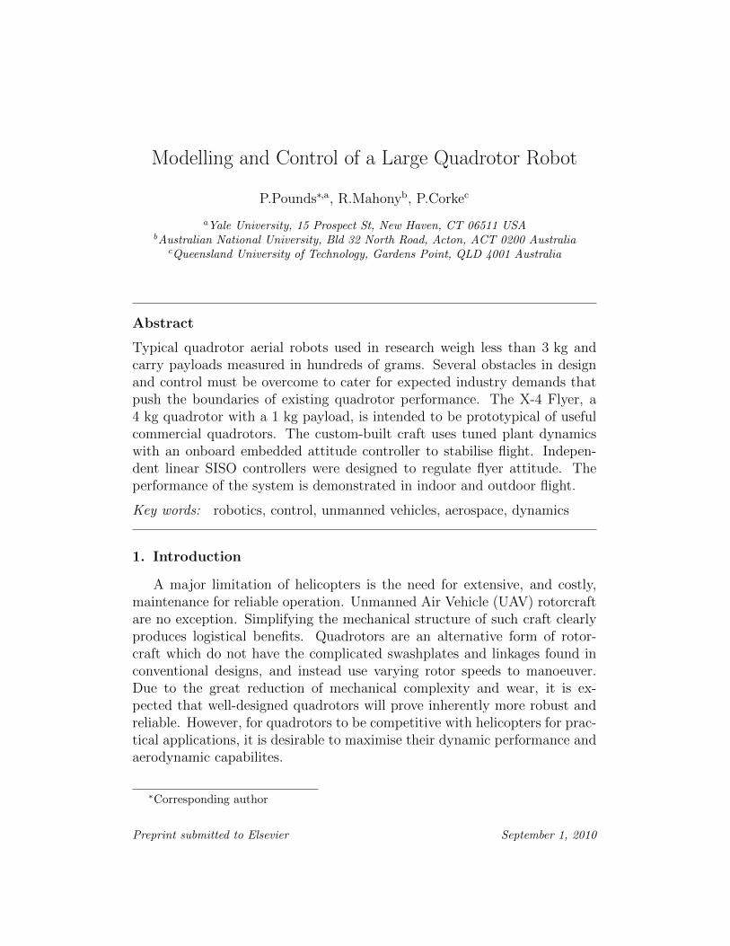
Figure 1: The X-4 Flyer.
being the maximisation of quadrotor aerodynamic and control performanceto meet increasing demands of operators. While many tasks can be performedwith small payloads and short flight-times, larger loads and longer flight-times represent greater utility for a commercial vehicle.
This challenge can be met by increasing the size and power of the vehi-cle. The thrust produced by a rotor is proportional to the fourth power ofits radius and the square of its angular velocity. The input power requiredin hover is inversely proportional to radius, which motivates use of largervehicles and higher power rotors for increased performance. The major lim-itations on helicopter size are structural, where rotors become so large thatthey droop towards the ground. The weight and dynamics of rotors haveramifications for the control performance that can be realised.
1.1. The X-4 Flyer
The Australian National University X-4 Flyer Mark III is a 4 kg quad-rotor with a 1 kg payload2. It was designed to develop high thrust in a smallfootprint, with only 20 per cent larger area than the RCtoys Draganflyer IV(see Fig. 1). This was seen as a step towards highly capable industrial quad-rotor UAVs. It uses custom high-performance rotors capable of lifting the
2It should be noted that there is no standard definition of payload. Carried weight canbe added up to the maximum rotor thrust, at the expense of control margin.
3

flyer with an additional 30 per cent control margin (total thrust greater than5.2 kg) [Pounds et al., 2009]. The motors and batteries used are off-the-shelfcomponents. The motors directly drive the rotors, eliminating the need for agearbox. The robot has only eight moving parts – four pivoting rotor mountsand four motor hubs. As a result, the flyer is mechanically reliable with littlescope for catastrophic failure in flight.
In this paper the critical control aspects of heavy quadrotors are reported:rotor speed control and attitude dynamic control. The dynamics of quad-rotor helicopters with blade flapping are examined in detail. Based on the6DOF aerodynamic model, decoupled dynamics in longitudinal (pitch/roll)and azimuthal modes are derived. We use this model to optimise the me-chanical design of the X-4 Flyer for control of these dynamics and implementlinear SISO control in the decoupled dynamics. The controller is tested on agimbal rig and the performance realised in indoor and outdoor flight tests isreported. Findings are summarised with a brief conclusion.
2. Drive System
Efficient, compact, high-lift rotors are essential for quadrotor UAV appli-cation flight time and payload needs. Previous efforts to design drive systemshave often consisted of an empirical approach, combining off-the-shelf parts[Bouabdallah et al., 2004a] [Nice, 2004], but for best performance rotors andmotors must be tuned to the specific needs of the aircraft. A method todesign a complete drive system suitable for large quadrotors has been previ-ously described [Pounds et al., 2009]. In this section the essential facets ofsystem design that apply to quadrotor control are reviewed.
2.1. Rotor Response Time
The swashplates of conventional helicopters allow instantaneous thrustchanges, whereas most quadrotors use fixed-pitch rotors and must thereforeaccelerate and decelerate their rotors to manoeuver. As rotor size increases,mass and rotational inertia also increase. The rotor drive system must becapable of developing enough torque to affect prompt response. It is desir-able to make the rotor and mast as light as possible to maximise actuatorbandwidth.
In the case of the X-4 Flyer, it was found that the natural rise-time ofthe rotor mount, blade and motor assembly is 0.2 seconds, which made the
4
vehicle uncontrollable. Feedback control was required to reduce the responsetime to 0.05 seconds [Pounds et al., 2009].
Especially large quadrotors may use collective variable blade pitch on eachrotor and avoid the motor dynamics problem entirely. This was the approachtaken by the Hoverbot [Borenstein, 1992]. The authors are not aware of anyUAVs of this sort that have been flown, but it is expected that this is a viablealternative. However, collective blade control comes at the cost of increasedmechanical complexity which abrogates the robustness advantage of simplerquadrotors.
2.2. Electronic Speed Control Hardware
Motor dynamic performance and robustness are crucial to quadrotor per-formance and reliability. Small quadrotors, such as the Draganflyer V, typi-cally employ single power FETs modulating drive voltage to each permanentmagnet DC motor. Larger craft employ brushless motors with electronicspeed controllers (ESC). Properly engineered ESCs are required to extractmaximum performance. Common practice has been to use off-the-shelf hobbyaircraft ESCs because they are readily available and light weight. However,these have several drawbacks.
Most importantly for quadrotors, hobby controllers often have a built-in slew-limit designed to reduce the in-rush current draw upon step speedchanges. Current spikes as high as 100 A have been measured in the X-4’sdrive [Pounds et al., 2009]. Without slew limitation, the in-rush current cancause the power bus voltage to sag from internal resistance of the batteries,leading to avionics resetting, and severe spikes can even cause damage theESC switching circuits. To avoid these problems, ESCs ramp speed changesslowly, increasing response time and limiting the bandwidth of the actuator.In the case of the X-4 Flyer, slew-limited hobby speed controllers could notrespond fast enough to stabilise the craft.
Generally, hobby ESC microcontroller code and internals are inaccessible;no direct ESC rotor speed measurement is available externally, which mayrequire additional sensors be added. It was found that high-gain, closed-loopspeed control around the 50 Hz update rate of hobby RC equipment was notfeasible for the X-4 Flyer. Programmable hobby ESCs now available canbe hooked up to PCs for fine-tuning — these may be adaptable for largequadrotor speed control. However, a commercial high-performance quad-rotor will almost certainly use custom drive electronics, as is the case with
5

the Ascending Technologies Hummingbird [Ascending Technologies GmbH,2009].
2.3. Dynamic Compensation
Quadrotors must have fast thrust dynamics — the motors must be ableto accelerate the rotors quickly to allow authorative attitude stabilisation.Most current quadrotors have light rotors that allow for fast speed changeswithout additional control. Large quadrotors have heavier, high inertia rotorsand thus need local control to artificially improve the motor bandwidth.Reflected rotor inertia through any gearing should also be matched to theinertia of the motor to allow for maximum acceleration, although this must bebalanced against the added mass, complexity and friction of a drive train. Inpractice, the closed-loop performance is most heavily constrained by limits onthe available instantaneous current draw on the batteries and this dominatesthe control design.
Brushless motor speed dynamics are a single-pole dynamic system, andproportional feedback control is suitable. The control gain that can be re-alised by the torque-limited plant is bound by the maximum slew-rate thatdisturbance noise and sinusoidal references may demand without inducingfailure in the controller. A method for calculating an optimised control de-sign for a slew-saturated drive has been previously described [Pounds et al.,2009].
Given sufficient bandwidth, the motor controller need not maintain pre-cise rotor speed — the attitude control system for a full UAV will containintegral terms that will compensate motor set-points to ensure flight stabilityof the vehicle.
3. Quadrotor Dynamics
Mathematical dynamic models of flight behaviour are essential for goodcontrol design and analysis. A common model used to represent quadrotorbehaviour is that of Hamel et al [Hamel et al., 2002]. The most basic quad-rotor model used consists only of rigid body dynamics with abstract forceand torque actuators and no aerodynamics. The quadrotor is commonly rep-resented as a rigid body mass with inertia and autogyroscopics, acted uponby gravity and control torques.
Simple quadrotor dynamic models do not represent the complex helicop-ter behaviour exhibited by real quadrotors. In particular, they omit the
6

Figure 2: Flapping Quadrotor Free-body Diagram.
blade flapping effect, which is critical to understanding oscillatory helicoptermodes, rotor flapping due to yaw and variable rotor inflow velocities as aresult of craft pitch and roll.
Flapping dynamics are beginning to be recognised as important aspectsof quadrotor dynamics; even very small quadrotors exhibit flapping [Huanget al., 2009]. The nature of the instability of quadrotor dynamics, oscilla-tory or pure divergence, was shown to be dependent upon the height of therotor above the centre of mass; setting the rotors to be on, or just above,the plane of the centre of gravity minimises the sensitivity function of thesystem [Pounds et al., 2006]. In the case of large quadrotors, where actuatorbandwidth is limited by slow rotor dynamics, this may be a crucial designpoint.
3.1. Rigid Body Dynamics
The inertial reference frame is denoted by I= {Ex, Ey, Ez}, where Ez isin the direction of gravity, and ξ = (x, y, z) is the origin of the body fixedframe A ={Ea
1 , Ea2 , E
a3} where x is aligned with the front of the craft(see
Fig. 2). The frame A is related to I by the rotation matrix R : A → I.Vectors v and ω are the linear and angular velocities of the frame in A.
7

The equations are:
ξ = Rv (1)
mv = −mω × v +mgRTe3 +∑
N,S,E,W
ti (2)
R = R · sk (ω) (3)
Iω = −ω × Iω +∑
N,S,E,W
[qi + mi] (4)
ti = CTρAr2ω2
i
− sin a1sicos a1si sin b1si− cos b1si cos a1si
(5)
qi = CQρAr3ωi|ωi|e3 (6)
mi = ti × di (7)
wherem and I are the mass and rotational inertia of the flyer, g is accelerationdue to gravity, ρ is the density of air, r is the rotor radius, and A is the rotordisc area. In equation 6, ω is multiplied by its magnitude to preserve thesign of rotation for counter-rotating rotors.
Here sk(x) is the skew-symmetric matrix such that sk(a)b = a × b forvectors in <3.
Rotors are indexed by their corresponding compass directions: North,South, East and West (NSEW ), where N indicates the front rotor. Corre-spondingly, di is the rotor displacement from the flyer centre of mass:
dN =(0 d h
)(8)
dS =(0 −d h
)(9)
dE =(d 0 h
)(10)
dW =(−d 0 h
)(11)
where d is the arm length of the flyer and h is the height of the rotors abovethe CoG.
Vectors ti and qi are the rotor thrust and torque, and mi is the momentdue to the thrust vector of the ith rotor — for a teetering rotor, the momentproduced by the rotor flapping is due solely to the thrust vector acting arounda displacement from the vehicle’s centre of gravity. The first harmonicsof the longitudinal and lateral flapping angles of the ith rotor are denotedby a1si and b1si , respectively. The non-dimensionalised thrust and torque
8
coefficients, CT and CQ, are treated as constants here. The speed of the ithrotor is given by ωi. The non-dimensionalised thrust coefficient and flappingequations are discussed in more detail in Sections 3.2 and 3.3.
3.2. Pitch and Roll Rotor Damping
A quadrotor necessarily has a horizontal displacement between its mastsand CoG. When the craft rolls and pitches, the rotors experience a verticalvelocity, leading to a change in the inflow angle. From Prouty [Prouty, 2002,p 101], CT can be related to the vertical velocity, Vc, by:
CT/σ =a(α)
4
[θtip −
vi + Vcωr
](12)
where a is the airfoil polar lift slope, θtip is the geometric blade angle at thetip of the rotor, vi is the induced velocity through the rotor, and σ is thesolidity of the disc — the ratio of the surface area of the blades and the rotordisc area. The added lift due to increased flow velocity magnitude at theblade is small relative to the effect of changing inflow angle, and is ignored.
The polar lift slope is itself a function of the rotor blade angle of attack,α. It is highly nonlinear for some airfoils and so the relation can be betterexpressed as a variation around a set point, CT0:
CTi = CT0 + ∆CTi (13)
where ∆CT is the change induced by the changing inflow conditions. FromEquation 12, this is written as:
∆CTi = −a04
σ
ωir(v + ω × di)e3 (14)
where a0 is the lift slope at the set point.The inflow velocity of the X-4’s rotors is very high with respect to pitch,
roll and translation velocities. Consequently, the vehicle does not readilyinduce vortex ring states, even during aggressive manoeuvres.
3.3. Blade Flapping
When the rotors translate horizontally there is a difference in blade liftbetween the advancing and retreating blades, which causes the rotor tippath plane to tilt. The resulting angle of the rotor plane is obtained by si-multaneously solving the constant and sinusoidal components of the blade
9

Figure 3: Blade Flapping Angle Rotation.
centrifugal-aerodynamic-static weight moment system. Flapping is impor-tant, as the tilting rotor can introduce significant stability effects for thevehicle [Pounds et al., 2006].
The dynamics of rotor flapping are very fast, occurring within one revo-lution of the rotor [Leishman, 2006], compared with the rigid body dynamicsof the helicopter. Consequently, the blade flapping equations can be writtenas instantaneous functions of the craft’s planar velocity.
A quadrotor’s flight is not limited to longitudinal motion – when thevehicle moves laterally or yaws the principal flapping axis need not be alignedto the front of the aircraft. The flapping of the ith rotor due to planar motionis found by calculating the magnitude and direction of rotor’s translationand defining a local frame of reference, Bi, aligned in that direction. Thelongitudinal and lateral flapping angles are calculated in the rotor frame (u1siand v1si) and then re-expressed in the body-fixed frame (a1si and b1si) usinga rotation matrix (see Fig. 3). This allows the avoidance of computationalcomplexity by using standard flapping equations in the local frame.
The per-rotor flapping is found by first computing the advance ratio andazimuthal direction of the rotor. This is derived as:
10
vri = v + ω × di (15)
µri =‖vr(1,2)i‖ωir
(16)
ψri = arctan
(vr(2)ivr(1)i
)(17)
where vr(n)i is the nth element of the ith rotor’s velocity vector, µri is theith rotor’s advance ratio and ψri is the azimuthal direction of motion.
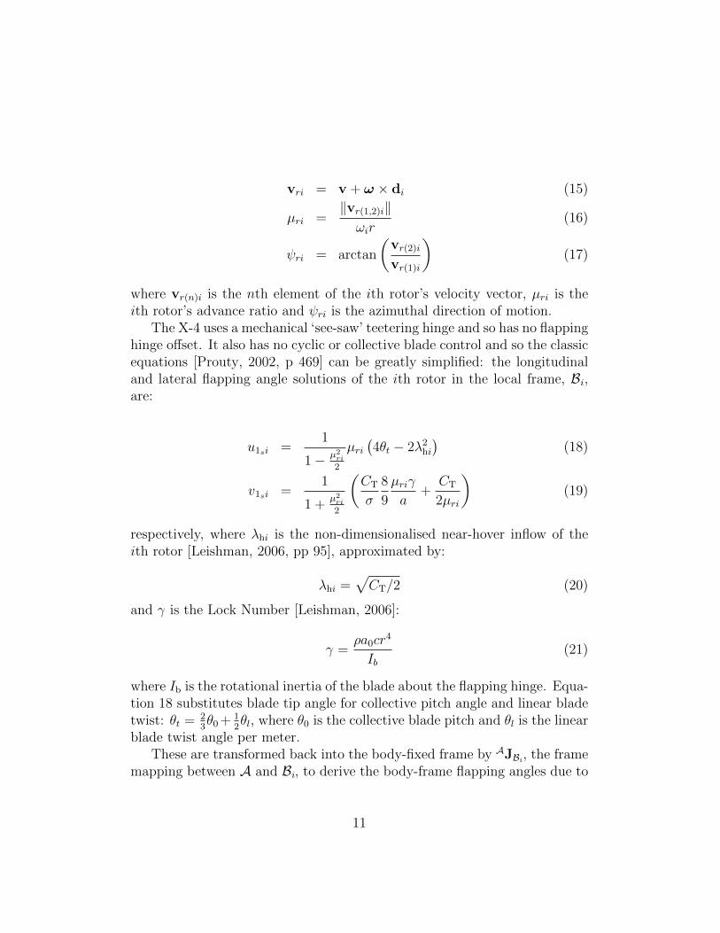
The X-4 uses a mechanical ‘see-saw’ teetering hinge and so has no flappinghinge offset. It also has no cyclic or collective blade control and so the classicequations [Prouty, 2002, p 469] can be greatly simplified: the longitudinaland lateral flapping angle solutions of the ith rotor in the local frame, Bi,are:
u1si =1
1− µ2ri2
µri(4θt − 2λ2hi
)(18)
v1si =1
1 +µ2ri2
(CT
σ
8
9
µriγ
a+
CT
2µri
)(19)
respectively, where λhi is the non-dimensionalised near-hover inflow of theith rotor [Leishman, 2006, pp 95], approximated by:
λhi =√CT/2 (20)
and γ is the Lock Number [Leishman, 2006]:
γ =ρa0cr
4
Ib(21)
where Ib is the rotational inertia of the blade about the flapping hinge. Equa-tion 18 substitutes blade tip angle for collective pitch angle and linear bladetwist: θt = 2
3θ0 + 1
2θl, where θ0 is the collective blade pitch and θl is the linear
blade twist angle per meter.These are transformed back into the body-fixed frame by AJBi , the frame
mapping between A and Bi, to derive the body-frame flapping angles due to
11

motion of the flyer:
AJBi =
(cosψri − sinψrisinψri cosψri
)(22)(
a1sib1si
)= AJBi
(u1siv1si
)(23)
The components of the flapping angles produced by the craft’s pitch androll rates [Prouty, 2002, p 473] are added to those of the body-fixed frame:
a1si = . . .+−16
γ
(qω
)+(pω
)1− µ2i
2
(24)
b1si = . . .+−16
γ
(pω
)+(pω
)1 +
µ2i2
(25)
4. Model Parameterisation and Stability
High-performance quadrotor attitude regulation poses additional chal-lenges due to the need to consider more completely the dynamics expressedby rotorcraft and the difficulty in parameterising and testing controllers priorto flight. In this section the implications of large quadrotor dynamics andprincipal considerations for attitude controller design are discussed.
4.1. Parameterisation and Uncertainty
Robustness to plant uncertainty is essential for high-performance control.It is difficult to perform classic step response experiments to characterise thevehicle in flight prior to developing a basic stabilising controller — instabilitycaused by erroneous control is liable to severely damage or destroy fragilecraft.
Most of the plant model parameters are dictated by physical constantsor the flight characteristics of the system; some, most importantly h, can bechosen freely. The error associated with each parameter defines the envelopeof the plant model’s dynamic response. The system behaviour within thisenvelope is analysed to determine the best value of h, the height of the rotorsabove the CoG.
A set of parameter estimates, taken directly from measurements or de-rived from experiments, are known along with the associated error. In thecase of parameters computed from other known values, the associated errorswere also computed:
12

• Aerodynamic parametersRotor, blade and aerodynamic parameters are obtained through mea-surement, computation, simulation or from references. These are listedin Table 1.
• Masses and DisplacementsComponent masses and distances measured with respect to the rotorplane, (masses ±0.005 kg, distances ±0.005 m) are given in Table 2.Note that this table is not a complete listing of all masses, but includesall major masses — screws and fasteners are omitted (see Fig. 4).
Figure 4: X-4 Component Offsets.
• Rotational InertiaComputed from the previous values by treating the parts as pointmasses, the diagonal entries of the inertial matrix are given in Table 3.The CoG is 0.0071± 0.005 m above the rotor plane.
4.2. Unforced Stability Analysis
The dominant dynamics of a helicopter, or a quadrotor, are associatedwith the longitudinal dynamics of the vehicle. Around hover, the motion ofa helicopter is largely decoupled in each axis. The symmetry of quadrotorsmeans that the important attitude dynamics can be described by a singleequation.
The natural stability of these dynamics is analysed to provide insightinto the best airframe geometry for controllability of the system. Prouty’sstability analysis of the near-hover dynamics of helicopters is employed, withthe addition of terms specific to quadrotors.
13

From the basic dynamic equations for a helicopter constrained to translatein x and rotate in pitch only without control inputs, the stability derivativematrix is [Prouty, 2002, p 564]:∣∣∣∣−ms+ ∂X
∂x∂X∂θs−mg
∂M∂x
−IY Y s2 + ∂M∂θs
∣∣∣∣ ∣∣∣∣xθ∣∣∣∣ = 0 (26)
where x is the longitudinal position, θ is the pitch angle and s is the Laplacetransform of the differential operator. The longitudinal force, X, and pitchmoment, M , stability derivatives for a teetering hinge, fixed pitch rotor are:
∂X
∂x= −ρA(ω0r)
2
(3
2
CT
σ
(1− a
12
θtCT/σ
))4θt − 2λhω0r
(27)
∂X
∂θ= −ρA(ω0r)
2
(3
2
CT
σ
(1− a
2
θtCT/σ
))(28)
∂M
∂x= −∂X
∂xh (29)
∂M
∂θ=
∂X
∂θh (30)
For quadrotors, ∂M/∂x, and ∂X/∂x are multiplied by 4 (for four rotors).A term is also added to ∂M/∂θ for the vertical motion of the rotors throughtheir inflow in pitch and roll:
∂M
∂θ= . . .− ρA(ωR)22d
∂CT
∂θ(31)
where:∂CT
∂θ=−a8σ
1
ωR(32)
The characteristic equation of the system matrix determinant, in canon-ical form of As3 +Bs2 + Cs+D, becomes:
s3 −(
1
m
∂X
∂x+
1
IY Y
∂M
∂θ
)s2 +
g
IY Y
∂M
∂x= 0 (33)
Solving for the roots of this polynomial gives the exponential components ofthe dynamic behaviour of the system.
14

Application of Routh’s Discriminant, as outlined in Prouty, uses the co-efficients of the characteristic polynomial, A, B, C and D, to determine thenature of the instability [Prouty, 2002, p 602]. From equation 33:
A = 1 (34)
B = −(
1
m
∂X
∂x+
1
IY Y
∂M
∂θ
)(35)
C = 0 (36)
D =g
IY Y
∂M
∂x(37)
The Routh’s Discriminant, R.D., is given by:
R.D. = BC − AD (38)
If all coefficients are positive, there will be no pure divergence. If R.D.is positive, the craft will exhibit no unstable oscillation. If negative, thecraft will exhibit unstable oscillation. If zero, the pitch dynamic will beneutral. As C = 0, there is no way to satisfy the first and second conditionssimultaneously, and so the system cannot be made stable. Substituting thecoefficients into equation 38 and simplifying, R.D. becomes:
R.D. = −CTρA (ωr)2 h (39)
Of the composing terms, only h can change signs. For a conventionalhelicopter, where h > 0, the craft has an unstable pole pair. If the rotors areinverted (above the CoG), the craft will diverge without oscillation. If therotors and CoG are coplanar, the craft is neutral.
4.3. Parameterised Model Envelope
Using the physical values for the X-4 Flyer, the coupled pitch and xtranslational dynamical equations can be computed. The error range of theparameters maps the roots of the plant into a space on the complex plane.Linearised differential equations for the flyer are taken from solving equations1 – 25 for acceleration in pitch and x translation:
mx = −mga1s −mgθ (40)
IY Y θ = 4dCTρAr2ω0δω +mga1sh−
a
2σρArω0d
2θ (41)
15

These can be solved by substituting equations 23, 24 and 40 into 41,where equation 16 becomes x/(ω0r), to produce a single transfer functionH = θ/δω between pitch angle, θ, and the input differential change in rotorspeeds, δω:
H =4dCTrc2(s+ gc1)
(s+ gc1)(IY Y s2 − hmgc3s+ a02σc2d2s) + hmg (gc3s− g))
(42)
where:
c1 =4θt − 2λ
ω0r(43)
c2 = ρArω0 (44)
c3 =16
γω0
(45)
The flapping angle is approximated as a linear function of x and θ:
a1s = c1x+ c3θ (46)
Using the system parameters and errors, the poles and zeros of the systemare given in Table 4. The rotor height above the CoG is the predominantcontributor to error, thus accurate knowledge of the rotor height is importantto determining the dynamic model.
The unforced stability analysis demonstrated that h is also importantin determining the behaviour of the dynamic system. The root locus for hshows that the structure of the open-loop poles changes significantly as hchanges sign (see Fig. 5): the system exhibits an unstable oscillation whenthe CoG is below the rotor, pure divergence when it is above the rotor, andneutral stability when coincident with the rotor.
5. Design for Control
The use of automatic compensators no longer requires that a systembe intuitive for a human pilot, and so oscillatory systems are acceptable.Instead, the fundamental limits of control can be employed to adjust theplant for best controller performance.
Strong disturbance rejection and fast response to input commands aredesired for good performance. However, the ‘water-bed effect’ of the Bode
16

Figure 5: Root Locus of Pitch Dynamics for Changing Rotor Height Above CoG.
integral for the sensitivity function imposes a limit on arbitrary design targetsfor the controller across all frequencies: it states that any arbitrary reductionin the sensitivity of the system implies a corresponding increase in sensitivityover other frequencies [Seron et al., 1997].
In the case of the X-4 Flyer, both low frequency disturbances, which causedrift, and high frequency disturbances, which induce noise in the inertialsensors, must be rejected. For this reason, it is desirable to reduce the integralof sensitivity function across the underlying system, prior to the applicationof any control.
The sensitivity function can be related directly to the poles of the open-loop plant through the Bode integral. From Seron et al :∫ ∞
0
log |S(ejω)|dω = π
np∑i=1
pi (47)
where S is the sensitivity function of the system, pi are the poles of the openloop plant, and ω is frequency [Seron et al., 1997].
Calculating the Bode integral for a range of h from −0.05 to 0.05 m belowthe rotor demonstrates a sharp notch at h = 0 (see Fig. 6). When the rotorplane is coincident with the center of gravity, the Bode integral is zero. Inthis configuration, the pitch dynamic is neutral.
The magnitude of the integral changes sharply as the rotor plane movesaway from the CoG. Given the strong correlation between h error and plant
17

Figure 6: Bode Integral With Respect to Rotor Plane Placement.
structure, and the link between sensitivity and h position, it is clear that closeattention to the correct tuning and verification of rotor height is essential forthe performance of the helicopter.
For the X-4 Flyer, the ideal rotor position is at h = 0. However, as theroot locus with changing h demonstrates, the structure of the plant undergoessignificant change with error around this point. For this reason, the CoG isset slightly away from the rotor plane so that small errors will not have animpact on stability. The Bode integral corresponding to the rotor position,with error bars, is shown on Fig. 6. Although more difficult to control by ahuman, this choice maximises the achievable performance of the closed-loopsystem.
6. Attitude Control
Quadrotor attitude control has been well researched by groups at manyuniversities. A variety of control techniques has been implemented success-fully on quadrotor UAVs — PID, LQ, feedback linearisation, nonlinear PDand PD2 [Bouabdallah et al., 2004b], backstepping [Guenard et al., 2005],adaptive nonlinear control, sliding-mode [Waslander et al., 2005] and robustcontrol.
In practice, the performance of simple control schemes are competitivewith even very complex schemes. The dynamic regulation performance ofmost controllers is within ± 2 degrees of level tracking, and the best in the
18

range of ± 0.5 to 1 degrees. It is the authors’ assertion that the limitingfactor in quadrotor dynamic control is the performance of the actuators.It has been suggested that less complicated designs such as PID may, infact, offer an advantage due to their simplicity and potential robustness toparameter variation [Bouabdallah et al., 2004b]. These qualities are desirablefor our full flapping model which is especially sensitive to changes in h.
In addition to the attitude dynamics, the X-4 Flyer also has importantmotor dynamics. The motor dynamics act in series with the rigid bodydynamics – fast motor response is important for authoritive attitude controlof quadrotors. To this end, rotor speed controllers have been developed toimprove the natural performance of the rotor-motor system [Pounds et al.,2009]. The linearised closed-loop motor system transfer function, HM-CL, is:
HM-CL =68.85(s+ 0.42)
(s+ 78.46)(s+ 0.44)(48)
6.1. Discretised Model
The controller runs at 50 Hz, the maximum frequency at which attitudedata is updated, and so the dynamics of the plant are discretised at ts =0.02 seconds for the control design. The IMU returns both angle and rateinformation, which allows for a PID controller in the improper form C =k(1+ i/s+ds) to be realised, where C is the controller transfer function, k isthe proportional system gain, i and d are the integral and differential scalingsand e is the system error. The complete discretised model, Gc = θ/δω, is:
Gc =1.4343× 10⁻⁵(z − 0.9916)(z + 1)(z − 0.9997)
(z − 0.2082)(z − 0.9914)(z − 1.038)(z2 − 1.943z + 0.9448)(49)
where δω is the differential variation in rotor speed about the operatingcondition, 850 rad·s−1. The additional zero at z = −1 comes from thematched pole-zero discretisation method.
6.2. Controller Design
The proposed controller consists of a discrete PID controller. The transferfunction of the controller, C, is:
C = 400
(1 + 0.2
0.02
(z − 1)+ 0.3
(z − 1)
0.02
)(50)
19

As the motor dynamics are so fast, the dominant pole has little interactionwith the attitude mechanics. If it were slower, the excess poles would divergecloser to the unit circle, leading to oscillation and possibly instability. Theslow motor pole-zero cancellation is associated with the dynamics of thelithium ion polymer cells, and sufficient gain causes the pole to close withthe zero.
7. Flight Testing and Performance
The X-4 underwent extensive testing prior to free flight outdoors. Withthe exception of the outdoor flight, all tests were performed in a test cagein the ANU Mechatronics Laboratory. The X-4’s high speed rotors are quitedangerous and untethered indoor and outdoor flights were not attempted un-til confidence in the vehicle was established. Prior to the designed controllerbeing tested under flight conditions, controller functionality was validatedwith the X-4 fixed on a gimbal rig at low rotor speed [Pounds et al., 2006].
For testing with translational freedom the aircraft was suspended justabove the ground at start-up and then the controller was turned on as therotors were brought up to flight speed. Integral gain was previously turnedoff to avoid wind-up conditions during testing. In this test the attitudecontroller was:
C = 400
(1 + 0.3
(z − 1)
0.02
)(51)
The zero integral gain caused the flyer to stabilise at non-zero angles. TheX-4 lifted itself in ground effect (0.4 m) and regulated its attitude within ±1degree of equilibrium (see Fig. 7).
For testing beyond ground effect the X-4 was flown tethered indoors. Af-ter engaging the attitude controller the suspended flyer was hoisted up 1.5 minto the air before bringing the rotors to flight speed. A pilot sent attitudereference commands to the flyer to keep it centered in the test area; the pilotdid not stabilise the vehicle. The X-4 flew at a height of approximately 2 m(see Fig. 8).
The outdoor test took place on an ANU sports field. A smooth platformwas used for take-off to allow the flyer to slide sideways freely rather thancatch and flip. To avoid integrator wind-up, the X-4 was brought up toflight speed, then hopped into the air under manual mode before switchingto autonomous control. During the flight a pilot sent commands to theflyer to control throttle but did not stabilise the vehicle. The X-4 took off
20
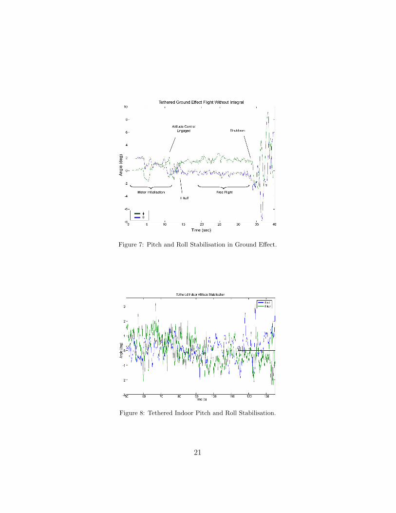
Figure 7: Pitch and Roll Stabilisation in Ground Effect.
Figure 8: Tethered Indoor Pitch and Roll Stabilisation.
21
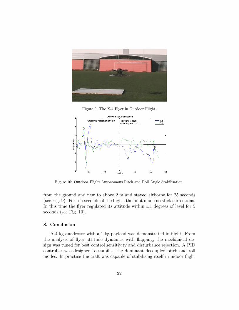
Figure 9: The X-4 Flyer in Outdoor Flight.
Figure 10: Outdoor Flight Autonomous Pitch and Roll Angle Stabilisation.
from the ground and flew to above 2 m and stayed airborne for 25 seconds(see Fig. 9). For ten seconds of the flight, the pilot made no stick corrections.In this time the flyer regulated its attitude within ±1 degrees of level for 5seconds (see Fig. 10).
8. Conclusion
A 4 kg quadrotor with a 1 kg payload was demonstrated in flight. Fromthe analysis of flyer attitude dynamics with flapping, the mechanical de-sign was tuned for best control sensitivity and disturbance rejection. A PIDcontroller was designed to stabilise the dominant decoupled pitch and rollmodes. In practice the craft was capable of stabilising itself in indoor flight
22

with ± 1 degree of level precision, and outdoors in a short flight with compa-rable attitude precision. However, extensive tests have yet to be conducted.To the authors’ knowledge, this is the first successful outdoor test of a >4 kgquadrotor UAV.
The X-4 project is now concluded, but many lessons about practical largequadrotor development have been learned. It was seen that good control andcareful plant design are important for realising good system performance,especially for slow, bandwidth limited craft. The next steps in developingthis system include further exploration of rotor dynamics unique to quad-rotors, and modernising motors, batteries and avionics. Newer IMU systemshave the potential for pushing system control performance with sample timesabove 100 Hz.
9. Acknowledgements
The authors would like to thank CSIRO ICT Robotics and Ryan Popefor their ongoing support of this project.
References
J Borenstein. The hoverbot — an electrically powered flying robot. 1992.ftp://ftp.eecs.umich.edu/people/johannb/paper99.pdf.
S Bouabdallah, P Murrieri, and R Siegwart. Design and control of an in-door micro quad-rotor. Proc. International Conference on Robotics andAutomation, 2004.
S Bouabdallah, A Noth, and R Siegwart. Pid vs lq control techniques appliedto an indoor micro quadrotor. Proc. IEEE/RSJ International Conferenceon Intelligent Robots and Systems, 2004.
N Guenard, T Hamel, and V Moreau. Dynamic modeling and intuitivecontrol strategy for an “x4-flyer”. Proc. 5th International Conference onControl and Automation, 2005.
T Hamel, R Mahony, R Lozano, and J Ostrowski. Dynamic modelling andconfiguration stabilization for an x4-flyer. Proc. 15th Triennial WorldCongress of the International Federation of Automatic Control, 2002.
23
H Huang, G Hoffman, S Waslander and C Tomlin. Aerodynamics and Controlof Autonomous Quadrotor Helicopters in Aggressive Maneuvering. In Proc.9th International Conference on Robotics and Automation, 2009.
JG Leishman. Principles of Helicopter Aerodynamics. Cambridge UniversityPress, Cambridge, United Kingdom, second edition, 2006.
Ascending Technologies GmbH, 2009. http://www.asctec.de/main/index.php.
Draganfly Innovations Inc, 2009. http://www.draganfly.com/.
E Nice. Design of a Four Rotor Hovering Vehicle. PhD thesis, CornellUniversity, 2004.
P Pounds, R Mahony, and P Corke. Modelling and Control of a QuadrotorRobot. Proc. Australasian Conference on Robotics and Automation, 2006.
P Pounds, R Mahony, and P Corke. Design of a static thruster for micro airvehicle rotorcraft. Journal of Aerospace Engineering, 22, 2009.
RW Prouty. Helicopter Performance, Stability and Control. Krieger Publish-ing Company, London, United Kingdom, first edition, 2002.
M Seron, J Braslavsky, and G Goodwin. Fundemental Limitations in Filter-ing and Control. Springer-Verlag, London, United Kingdom, first edition,1997.
S Waslander, G Hoffmann, J Jang, and C Tomlin. Multi-agent quadrotortestbed control design: Integral sliding mode vs. reinforcement learning.Proc. IEEE/RSJ International Conference on Intelligent Robots and Sys-tems, 2005.
10. Figure Captions
.Figure 1: The X-4 Flyer.Figure 2: Flapping Quadrotor Free-body Diagram.Figure 3: Blade Flapping Angle Rotation.Figure 4: X-4 Component Offsets.Figure 5: Root Locus of Pitch Dynamics for Changing Rotor Height Above
24

Value Error Unita0 5.5 ±0.5ctip 0.012 ±0.001 mm 4.34 ±5× 10⁻³ kgA 0.0855 ±0.1× 10⁻³ m2
CT 0.0047 ±0.2× 10⁻³
CQ 0.228× 10⁻³ ±0.015× 10⁻³
Ib 40.887× 10⁻⁶ ±3.655× 10⁻⁶ kg·m2
r 0.165 ±0.5× 10⁻³ mρ 1.184 Not available kg·m−3γ 1.417 ±0.133λ 0.049 ±2× 10⁻³
θtip 4.4 ±0.5 degσ 0.054 ±1× 10⁻³
ωhover 850 ±5 rad·s−1
Table 1: Aerodynamic Parameters and Associated Error.
CoG.Figure 6: Bode Integral With Respect to Rotor Plane Placement.Figure 7: Pitch and Roll Stabilisation in Ground Effect.Figure 8: Tethered Indoor Pitch and Roll Stabilisation.Figure 9: The X-4 Flyer in Outdoor Flight.Figure 10: Outdoor Flight Autonomous Pitch and Roll Angle Stabilisation.
11. Tables
25

Part mass/kg d/m e/m h/mA Avionics 0.242 0 0 -0.02B Rotor 0.046 0.315 0 0C Motor 0.288 0.315 0 -0.06D ESC 0.074 0.15 0.035 -0.055E Powerbus 0.099 0 0 -0.13F Battlong 0.165 0.0125 0.06 0.035G Battlat 0.165 0.0 0.04 0.035H Arm 0.039 0.157 0.035 0.04I Hoop 0.200 0 0 -0.17
Table 2: Component Masses and Offsets.
Value Error UnitIXX 0.0820 ±0.0025 kg·m2
IY Y 0.0845 ±0.0029 kg·m2
IZZ 0.1377 ±0.0059 kg·m2
Table 3: Diagonal Inertial Elements.
Value Errorp1 −2.507 + 2.671i ±0.714 + 1.244ip2 −2.507− 2.671i ±0.714 + 1.244ip3 2.578 ±1.129z -0.015 ±0.003
Table 4: Poles and Zeros of the Open Loop Pitch Dynamics.
26
Related Documents