Aerospace Science and Technology 29 (2013) 453–461 Contents lists available at SciVerse ScienceDirect Aerospace Science and Technology www.elsevier.com/locate/aescte Modelling and configuration control of wing-shaped bi-stable piezoelectric composites under aerodynamic loads Andres F. Arrieta a,∗ , Onur Bilgen b , Michael I. Friswell c , Paolo Ermanni a a Centre of Structure Technologies, ETH Zurich, Leonhardstrasse 27, Zurich, CH-8092, Switzerland b Old Dominion University, Department of Mechanical and Aerospace Engineering, Norfolk, VA 23529, USA c College of Engineering, Swansea University, Singleton Park, Swansea, SA2 8PP, UK article info abstract Article history: Received 11 December 2012 Received in revised form 23 April 2013 Accepted 9 May 2013 Available online 20 May 2013 Keywords: Bi-stable wing Unsymmetric composite Morphing Snap-through Bi-stable composites have been considered for morphing applications thanks to their ability to hold two statically stable shapes with no energy consumption. In this paper, the modelling of the dynamic response of cantilevered wing-shaped bi-stable composites is presented. To this end, an analytical model approximating the dynamic response about each statically stable shape of wing-shaped bi- stable composites is derived. Theoretical modal properties are obtained to attain or stabilise a desired configuration following a previously introduced resonant control strategy. The resonant control technique is evaluated for a wing-shaped bi-stable composite subject to aerodynamic loads. Wind tunnel experiments are conducted on a wing-shaped specimen showing the ability of the control strategy to stabilise or attain a desired stable shape under aerodynamic loads. © 2013 Elsevier Masson SAS. All rights reserved. 1. Introduction Bi-stable composites are structures capable of adopting two statically stable configurations [11]. The bi-stability property has drawn considerable attention from the adaptive structure commu- nity for its potential applications in morphing structures, as no energy is required to hold each of the stable configurations [10]. Multi-stability arises due to an induced stress field in the compos- ite laminates that can result from several mechanisms, including unsymmetrical lamination [12], tailored lay-up [17], pre-stressed cylinders [13], fibre pre-stressing [8] and thickness variation [9]. The change between stable states is physically realised as a jump phenomenon known as snap-through, which is strongly nonlin- ear in nature [2]. Different actuator systems and techniques have been previously used to trigger snap-through. Shape memory wires successfully achieved reversible changes between the stable states of bi-stable composites, however suffered of integration problems and reduced control bandwidth [7]. Quasi-static actuation employ- ing piezoelectric elements led to achieving snap-through only in one direction, nevertheless reversing the configuration to the orig- inal state was not possible due to insufficient actuation author- ity [19,16]. The recently introduced idea of exploiting the rich dynamics of bi-stable composites to enhance the actuation author- ity showed encouraging results [3,20]. In this context, Arrieta et al. [1] presented the implementation and demonstration of purely * Corresponding author. E-mail address: [email protected] (A.F. Arrieta). piezoelectric material dynamically induced forward and reverse snap-through of a bi-stable unsymmetric composite plate with a clamped edge. This resonant actuation strategy provided for the first time full configuration control of [0 n /90 n ] cantilevered bi- stable composites under the sole action of piezoelectric actuators. The implementation of multi-stable components in adaptable aerodynamic structures has the potential to reduce actuation re- quirements as energy is not required to hold a largely deformed shape. Hence, significant deflections can be achieved spending en- ergy only to trigger a snap-through from the original stable state to another. As with any active or semi-active compliant aerody- namic surface, a bi-stable piezoelectric composite wing is practical if sufficient aerodynamic load carrying capability in each state and bi-directional snap-through using relatively low excitation voltages are achieved. Such structures can be realised by careful selection of actuator placement, boundary conditions and laminate lay-up, coupled with the developed resonant control morphing strategy. An analytical model to obtain the modal frequencies for wing- shaped bi-stable composites is presented in this paper. The accu- rate prediction of the modal properties of such structures allows the application of the previously introduced resonant control tech- nique which has been shown to enable full configuration control on bi-stable composites. A wing-shaped bi-stable composite speci- men actuated with Macro-Fiber Composite (MFC) actuators is used to demonstrate this concept under the presence of aerodynamic loads. The use of MFC actuators allows the exploitation of the higher actuation authority obtained from the d 33 coupling coeffi- cient, by using interdigitated electrodes which guide the electrical field along the longitudinal direction of the fibres [27]. The d 33 1270-9638/$ – see front matter © 2013 Elsevier Masson SAS. All rights reserved. http://dx.doi.org/10.1016/j.ast.2013.05.004

Welcome message from author
This document is posted to help you gain knowledge. Please leave a comment to let me know what you think about it! Share it to your friends and learn new things together.
Transcript

Aerospace Science and Technology 29 (2013) 453–461
Contents lists available at SciVerse ScienceDirect
Aerospace Science and Technology
www.elsevier.com/locate/aescte
Modelling and configuration control of wing-shaped bi-stablepiezoelectric composites under aerodynamic loads
Andres F. Arrieta a,∗, Onur Bilgen b, Michael I. Friswell c, Paolo Ermanni a
a Centre of Structure Technologies, ETH Zurich, Leonhardstrasse 27, Zurich, CH-8092, Switzerlandb Old Dominion University, Department of Mechanical and Aerospace Engineering, Norfolk, VA 23529, USAc College of Engineering, Swansea University, Singleton Park, Swansea, SA2 8PP, UK
a r t i c l e i n f o a b s t r a c t
Article history:Received 11 December 2012Received in revised form 23 April 2013Accepted 9 May 2013Available online 20 May 2013
Keywords:Bi-stable wingUnsymmetric compositeMorphingSnap-through
Bi-stable composites have been considered for morphing applications thanks to their ability to holdtwo statically stable shapes with no energy consumption. In this paper, the modelling of the dynamicresponse of cantilevered wing-shaped bi-stable composites is presented. To this end, an analyticalmodel approximating the dynamic response about each statically stable shape of wing-shaped bi-stable composites is derived. Theoretical modal properties are obtained to attain or stabilise a desiredconfiguration following a previously introduced resonant control strategy. The resonant control techniqueis evaluated for a wing-shaped bi-stable composite subject to aerodynamic loads. Wind tunnelexperiments are conducted on a wing-shaped specimen showing the ability of the control strategy tostabilise or attain a desired stable shape under aerodynamic loads.
© 2013 Elsevier Masson SAS. All rights reserved.
1. Introduction
Bi-stable composites are structures capable of adopting twostatically stable configurations [11]. The bi-stability property hasdrawn considerable attention from the adaptive structure commu-nity for its potential applications in morphing structures, as noenergy is required to hold each of the stable configurations [10].Multi-stability arises due to an induced stress field in the compos-ite laminates that can result from several mechanisms, includingunsymmetrical lamination [12], tailored lay-up [17], pre-stressedcylinders [13], fibre pre-stressing [8] and thickness variation [9].The change between stable states is physically realised as a jumpphenomenon known as snap-through, which is strongly nonlin-ear in nature [2]. Different actuator systems and techniques havebeen previously used to trigger snap-through. Shape memory wiressuccessfully achieved reversible changes between the stable statesof bi-stable composites, however suffered of integration problemsand reduced control bandwidth [7]. Quasi-static actuation employ-ing piezoelectric elements led to achieving snap-through only inone direction, nevertheless reversing the configuration to the orig-inal state was not possible due to insufficient actuation author-ity [19,16]. The recently introduced idea of exploiting the richdynamics of bi-stable composites to enhance the actuation author-ity showed encouraging results [3,20]. In this context, Arrieta etal. [1] presented the implementation and demonstration of purely
* Corresponding author.E-mail address: [email protected] (A.F. Arrieta).
1270-9638/$ – see front matter © 2013 Elsevier Masson SAS. All rights reserved.http://dx.doi.org/10.1016/j.ast.2013.05.004
piezoelectric material dynamically induced forward and reversesnap-through of a bi-stable unsymmetric composite plate with aclamped edge. This resonant actuation strategy provided for thefirst time full configuration control of [0n/90n] cantilevered bi-stable composites under the sole action of piezoelectric actuators.
The implementation of multi-stable components in adaptableaerodynamic structures has the potential to reduce actuation re-quirements as energy is not required to hold a largely deformedshape. Hence, significant deflections can be achieved spending en-ergy only to trigger a snap-through from the original stable stateto another. As with any active or semi-active compliant aerody-namic surface, a bi-stable piezoelectric composite wing is practicalif sufficient aerodynamic load carrying capability in each state andbi-directional snap-through using relatively low excitation voltagesare achieved. Such structures can be realised by careful selectionof actuator placement, boundary conditions and laminate lay-up,coupled with the developed resonant control morphing strategy.
An analytical model to obtain the modal frequencies for wing-shaped bi-stable composites is presented in this paper. The accu-rate prediction of the modal properties of such structures allowsthe application of the previously introduced resonant control tech-nique which has been shown to enable full configuration controlon bi-stable composites. A wing-shaped bi-stable composite speci-men actuated with Macro-Fiber Composite (MFC) actuators is usedto demonstrate this concept under the presence of aerodynamicloads. The use of MFC actuators allows the exploitation of thehigher actuation authority obtained from the d33 coupling coeffi-cient, by using interdigitated electrodes which guide the electricalfield along the longitudinal direction of the fibres [27]. The d33
454 A.F. Arrieta et al. / Aerospace Science and Technology 29 (2013) 453–461
Fig. 1. Bifurcation diagram showing the statically stable configurations of a bi-stable composite. Equilibrium points a and c lying on the red and green branches correspondto the resulting shapes of State 1 and 2, respectively. (For interpretation of the references to colour in this figure legend, the reader is referred to the web version of thispaper.)
coefficient is larger than the conventionally used d31 coupling co-efficient. To achieve morphing control between the stable shapes,a model for the dynamics of the wing-shaped bi-stable compositesabout the statically stable shapes is developed. To this end, an an-alytical model approximating the linear dynamics for wing-shapedbi-stable composites about the predicted stable configuration is de-rived. This model allows to calculate the modal characteristics ofwing-shaped bi-stable composites, which are crucial for the cor-rect application of the resonant control technique. Furthermore,the analytical model allows the selection of the position piezo-electric actuators for maximum control authority in the requiredmodes. The parametric nature of the presented model allows forefficient sensitivity analyses and initial rapid optimisation to becarried out, while nonlinear finite element methods [23,24] can beused for final refinements at a later design stage. An experimentalcharacterisation is conducted using frequency response functions(FRF) validating the results obtained with the derived model. Theaerodynamic response of a tapered bi-stable wing-shaped speci-men is tested, showing the capabilities of the resonant actuationstrategy to control the configuration even against a certain level ofadverse pressure gradient. This characteristic allows for using suchbi-stable structures in morphing winglets applications. The paperconcludes with a brief summary of the presented results and dis-cussion of possible applications.
2. Modelling of bi-stable composites
In this study, laminates with a tapered planform arranged ina cantilever configuration are studied. To achieve this, a tailoredlay-up with symmetrical and unsymmetrical stacking sequences isused [14]. Bi-stability arises due to the unsymmetrically laminatedpart, as thermal stresses resulting from a mismatch between thethermal expansion coefficients of the fibres and the epoxy ma-trix are induced during cool down after curing. This process isschematically shown in Fig. 1, where w is the out-of-plane dis-placement, �T is the difference between the curing and the actualtemperatures, and F is the external load. Initially at the curingtemperature, the flat laminate configuration starts from point Co
o
from which it cools down reaching the bifurcation point Co′o , i.e.
following path �Coo Co′
o . At the bifurcation point, the cool down pro-cess can continue in either of the two stable branches until itreaches an equilibrium at room temperature, this is through path
�Co′o Co
a to equilibrium point Coa , or through path �Co′
o Coc to equilib-
rium point Coc . At room temperature, changes between the stable
states are caused by forcing a large deflection on the laminate trig-gering a snap-through [2]. The modelling of the shapes resultingfrom the bifurcation process and the dynamics around these stableconfigurations are presented in the following.
2.1. Variational formulation
A variational formulation is followed for the calculation of thefinal equilibrium shapes and the associated dynamic response ofthe studied wing-shaped bi-stable composites is presented. The La-grangian, L, for a bi-stable composite is equivalent to that of across-ply unsymmetrically laminated plate given by:
L = T − U +Wext, (1)
where T , U are the kinetic and potential energies, and Wext is thework done by external energy, respectively.
The kinetic energy of the system is the sum of the kinetic en-ergy of the composite and the piezoelectric elements, given by:
Ts = 1
2
∫V s
ρu̇′u̇ dV s, (2)
and
Tpzt = 1
2
Npzt∑k=1
∫V (k)
p
ρpztu̇′u̇ dV (k)
p , (3)
where the displacement field vector is defined as u = [u(x, y, t),v(x, y, t), w(x, y, t)]′ , ρ and ρpzt are the density of the composite
and the piezoelectric elements, respectively, V s and V (k)p are the
volume of the composite and the kth piezoelectric element, respec-tively, Npzt is the total number of piezoelectric elements bonded tothe bi-stable composite, the overdot (˙) symbol implies differenti-ation with respect to time, and the superscript (′) indicates thetranspose operation.
The total kinetic energy is thus written as:
T = Ts + Tpzt. (4)
The strain energy of the bi-stable plate is obtained by summingthe contributions of the symmetrical and unsymmetrical parts ofthe lay-up, yielding:
A.F. Arrieta et al. / Aerospace Science and Technology 29 (2013) 453–461 455
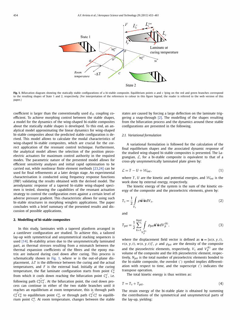
Fig. 2. Planform defining the domain of integration for the bi-stable wing.
Us =0∫
−LSymx
L y2∫
−L y2
1
2
([εo
κ
]′
Sym
(A BB D
)Sym
)[εo
κ
]Sym
dy dx
+LU
x∫0
sx+ L y2∫
−L y2
1
2
([εo
κ
]′
U
(A BB D
)U
−[
NTMT
]′)[εo
κ
]U
dy dx,
(5)
where εo = [εoxx εo
yy εoxy]′ is the vector of in-plane strains, κ =
[κxx κyy κxy]′ is the vector of bending strains, and A, B, D repre-sent the well known extensional, bending–extension coupling, andbending stiffness matrices, respectively, and NT and MT are thethermal expansion force and moment vectors, respectively [22].The subscripts Sym and U indicate symmetric and unsymmetriclamination, respectively. The planform dimensions defining the in-tegration domain are given by the span of the unsymmetric region,Lu
x , the length of the symmetric region, LSymx , the chord length
at the clamped edge, L y , and the chord length of the tip, tp .The leading-edge slope defining the wing-shaped (tapered) formis given by s = tp−L y
LUx
. A detailed geometrical description of the
planform is presented in Fig. 2. The total strain is given by εi j =εo
i j + zκi j . Note that the symmetrical part does not exhibit result-ing thermal stresses. The nonlinear extensional strain and bendingcurvatures, εo
i j and κi j , respectively, are given by:
εoxx = ∂u
∂x+ 1
2
(∂ w
∂x
)2
, (6)
εoyy = ∂v
∂ y+ 1
2
(∂ w
∂ y
)2
, (7)
εoxy = ∂u
∂ y+ ∂v
∂x+ ∂ w
∂x
∂ w
∂ y, (8)
and,
κxx = −∂2 w
∂x2, (9)
κyy = −∂2 w
∂ y2, (10)
κxy = −2∂2 w
∂x∂ y. (11)
The piezoelectric strain energy and the internal electrical work aregiven by:
Upzt = 1
2
Npzt∑k=1
∫V (k)
p
S′pT dV (k)
p + 1
2
Npzt∑k=1
∫V (k)
p
E3D3 dV (k)p , (12)
where Sp is the vector of strains, T is the vector of material stress.The poling and extension directions of the piezoelectric elements,3, coincides with the in-plane x-direction, consistent with the MFCactuators that are employed. A state of plane stress is assumed forthe considered structures, thus the components of the stress and
strain vector for piezoelectric materials are related by the consti-tutive relations:⎡⎢⎣
σ11σ22σ12D3
⎤⎥⎦ =
⎛⎜⎜⎝
cE11 cE
12 0 −e33
cE12 cE
22 0 −e31
0 0 g E12 0
e33 e31 0 εS33
⎞⎟⎟⎠
⎡⎢⎣
ε11ε22ε12E3
⎤⎥⎦ , (13)
where σi j is total stress due to a strain in the i-direction actingon the j-direction, εi j is mechanical strain due to a deflection inthe i-direction acting on the j-direction, D3 is electrical displace-ment in the 3-direction, E3 is the electric field in the 3-direction,cE
i j is the elastic modulus due to a strain in the i-direction act-
ing on the j-direction, g Ei j is the shear modulus due to a strain
in the i-direction acting on the j-direction, ei j is the piezoelec-tric constant relating the poling direction i with the strain in thej-direction, and εS
33 is the permittivity coefficient relating the elec-trical displacement in the 3-direction with the poling direction ofthe piezoelectric material, respectively. The superscripts E and Sdenote that the relevant parameters are measured at constant elec-tric field and constant strain, respectively. The total strain energyfor the system is thus written as:
U = Us + Upzt. (14)
2.2. Equilibrium configurations
The room temperature shapes of the static equilibrium pointsare obtained by minimising the potential energy of the laminateUs . To approximate the large transverse static deflections due tothe cooling process the following polynomial shape functions areused:
uo(x, y) =N∑
i=1
N∑j=1
aijxi y j−1, (15)
vo(x, y) =N∑
i=1
N∑j=1
bijxi y j−1, (16)
wo(x, y) =N∑
i=1
N∑j=1
ci jxi+1 y j−1, (17)
where uo(x, y), yo(x, y) and wo(x, y) are the mid-plane displace-ments defining the static equilibrium shapes, aij xi y j , bij xi y j , andci j xi y j are the shape functions on each coordinate direction, and,N × N gives the total number of shape functions used on each ex-pansion. It is necessary to impose continuity of the displacementto account for the interaction of the symmetric and unsymmetricparts of the laminate. This is achieved by satisfying the followingconditions on the displacements:
uoSym(0, y) = uo
U (0, y), (18)
voSym(0, y) = vo
U (0, y), (19)
woSym(0, y) = wo
U (0, y), (20)
∂ woSym(0, y)
∂ y= ∂ wo
U (0, y)
∂ y. (21)
Substituting Eqs. (6)–(11) and Eqs. (15)–(17) into Eq. (5) the equi-librium shapes are found from:
∂U
∂αi= 0, (22)
where α = [aij,bij, ci j] is the vector of generalised static displace-ments. The stability of the equilibrium points, Co , is obtained by
k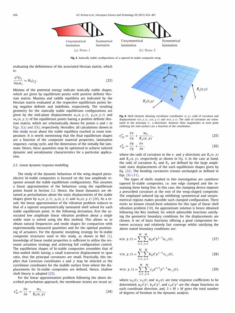
456 A.F. Arrieta et al. / Aerospace Science and Technology 29 (2013) 453–461
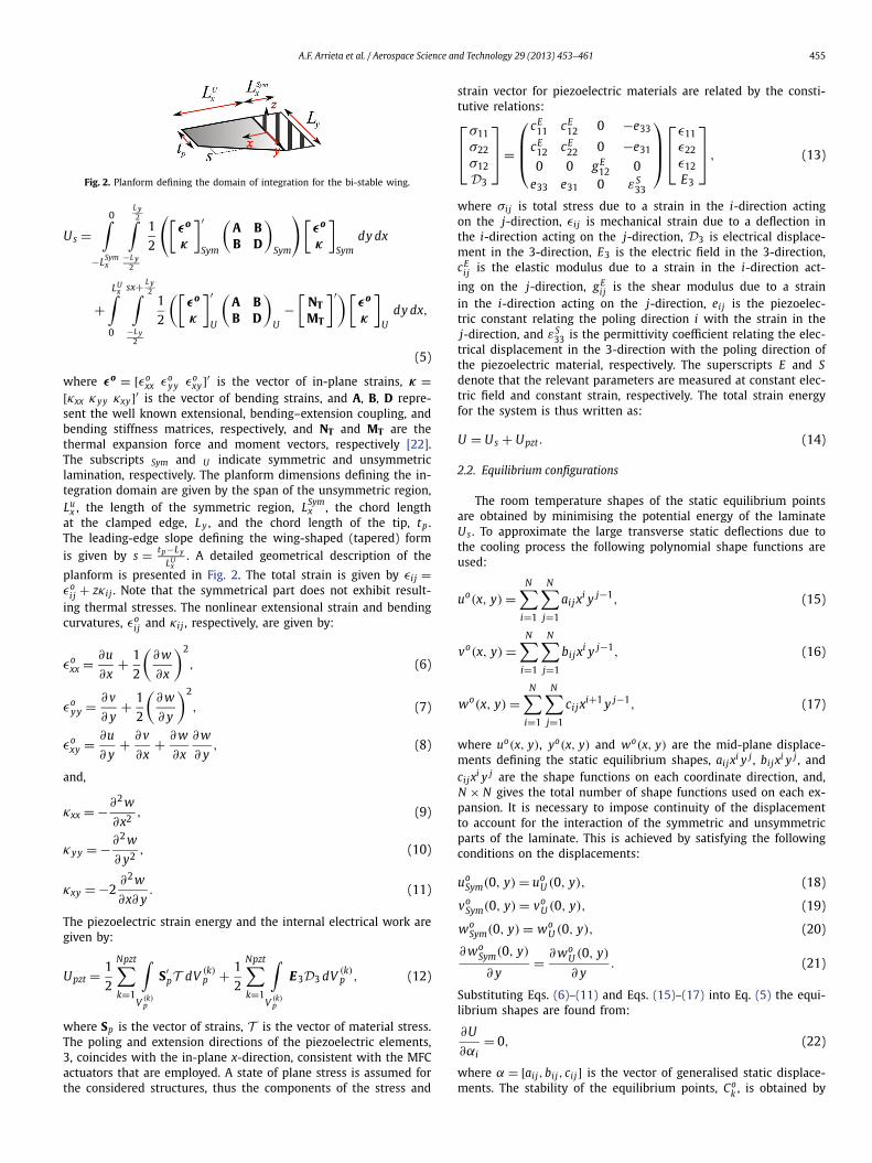
Fig. 3. Statically stable configurations of a tapered bi-stable composite wing.
evaluating the definiteness of the associated Hessian matrix, whichis:
∂2Us
∂αiα j= Hk|Co
k. (23)
Minima of the potential energy indicate statically stable shapes,which are given by equilibrium points with positive definite Hes-sian matrix. Maxima and saddle equilibria are indicated by theHessian matrix evaluated at the respective equilibrium points be-ing negative definite and indefinite, respectively. The resultinggeometry for the statically stable equilibrium configurations aregiven by the mid-plane displacements uo(x, y, t), yo(x, y, t) andwo(x, y, t) of the equilibrium points having a positive definite Hes-sian matrix, which are schematically shown for points a and c inFigs. 3(a) and 3(b), respectively. Hereafter, all calculations shown inthis study occur about the stable equilibria reached at room tem-perature. It is worth mentioning that the final equilibrium shapesare a function of the composite material properties, laminationsequence, curing cycle, and the dimensions of the initially flat lam-inate. Hence, these quantities may be optimised to achieve tailoreddynamic and aerodynamic characteristics for a particular applica-tion.
2.3. Linear dynamic response modelling
The study of the dynamic behaviour of the wing-shaped piezo-electric bi-stable composites is focused on the low amplitude re-sponse around the stable equilibrium configurations. This assumesa linear approximation of the behaviour using the equilibriumpoints found in Section 2.2. Hence, the linear dynamics are ob-tained as perturbations about the static displacements of the stableshapes given by uo(x, y, t), yo(x, y, t) and wo(x, y, t) [26]. As a re-sult, the linear approximation of the vibration problem reduces tothat of a tapered unsymmetrically laminated shell solved for eachstable equilibrium point. In the following derivation, first the as-sociated low amplitude linear vibration problem about a singlestable state is solved using the Ritz method. This allows us toobtain natural frequencies and mode shapes for comparison withexperimentally measured quantities and for the optimal position-ing of actuators. For the dynamic morphing strategy for bi-stablecomposite structures used in this study, as shown in Ref. [1],knowledge of linear modal properties is sufficient to utilise the res-onant actuation strategy and achieving full configuration control.The equilibrium shapes of bi-stable composites resembles that ofthin-walled shells having a small transverse displacement to spanratio, thus the principal curvatures are small. Practically, this im-plies that Cartesian coordinates x and y may be selected as thecurvilinear coordinates for the middle surface from where the dis-placements for bi-stable composites are defined. Hence, shallowshell theory is adopted [25].
For the linear approximation problem following the above de-scribed perturbation approach, the membrane strains are recast as:
εoxx = ∂u + wo
, (24)
∂x Rx(x, y)Fig. 4. Shell element showing curvilinear coordinates (x, y), radii of curvature anddisplacements u(x, y, t), y(x, y, t) and w(x, y, t). The radii of curvature are orien-tated in the principal x-, y-directions; however their magnitudes at each point(defining the mid-surface) are a function of the coordinates.
εoyy = ∂v
∂ y+ wo
R y(x, y), (25)
εoxy = ∂u
∂ y+ ∂v
∂x, (26)
where the radii of curvature in the x- and y-directions are Rx(x, y)
and R y(x, y), respectively as shown in Fig. 4. In the case at hand,the radii of curvature Rx and R y are defined by the large ampli-tude static displacements of the each equilibrium shapes given byEq. (22). The bending curvatures remain unchanged as defined inEqs. (9)–(11).
The types of shells studied in this investigation are cantilevertapered bi-stable composites, i.e. one edge clamped and the re-maining three being free. In this case, the clamping device imposesa prescribed curvature at the root of the wing-shaped composite.The employed tailored lay-up exhibiting symmetrical and unsym-metrical regions makes possible such clamped configuration. Thereexists no known closed-form solutions for this type of linear shellvibration problem [18]. An approximate solution is hence obtainedfollowing the Ritz method, for which admissible functions satisfy-ing the geometric boundary conditions for the displacements arechosen. A set of basis functions offering a good compromise be-tween accuracy and relatively fast converge whilst satisfying theabove stated boundary conditions are:
u(x, y, t) =M∑
i=1
M∑j=1
aijxi y j−1ui, j(t), (27)
v(x, y, t) =M∑
i=1
M∑j=1
bijxi y j−1 vi, j(t), (28)
w(x, y, t) =M∑
i=1
M∑j=1
ci jxi+1 y j−1 wi, j(t), (29)
where uij(t), vij(t) and wij(t) are time response coefficients to bedetermined, aij xi y j , bij xi y j , and ci j xi y j are the shape functions oneach coordinate direction, and, 3 × M × M gives the total numberof degrees of freedom in the dynamic analysis.
A.F. Arrieta et al. / Aerospace Science and Technology 29 (2013) 453–461 457
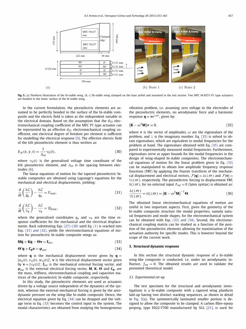
Fig. 5. (a) Planform illustration of the bi-stable wing. (b, c) Bi-stable wing clamped on the base airfoil and mounted in the test section. Two MFC M-8557-P1 type actuatorsare bonded to the lower surface of the bi-stable wing.
In the current formulation, the piezoelectric elements are as-sumed to be perfectly bonded to the surface of the bi-stable com-posite and the electric field is taken as the independent variable inthe electrical domain. Based on the assumption that the d33 elec-tromechanical coupling coefficient of the MFC P1 type actuator canbe represented by an effective d31 electromechanical coupling co-efficient, one electrical degree of freedom per element is sufficientfor modelling the electrical response [5]. The effective electric fieldof the kth piezoelectric element is thus written as:
E3k (x, y, t) = 1
�elvk(t), (30)
where vk(t) is the generalised voltage time coordinate of thekth piezoelectric element, and �el is the spacing between elec-trodes [6].
The linear equations of motion for the tapered piezoelectric bi-stable composites are obtained using Lagrange’s equations for themechanical and electrical displacements, yielding:
d
dt
(∂Lq̇a
)− ∂L
qa= Faext, (31)
d
dt
(∂Lv̇b
)− ∂Lvb
= Q bext, (32)
where the generalised coordinates qa and vb are the time re-sponse coefficients for the mechanical and the electrical displace-ments. Back substituting Eqs. (27)–(30) until Eq. (1) is reached intoEqs. (31) and (32), yields the electromechanical equations of mo-tion for piezoelectric bi-stable composite wings as:
Mq̈ + Kq − �v = fext, (33)
�′q + Cpv = ϕext, (34)
where q is the mechanical displacement vector given by q =[uij(t), vij(t), wij(t)]′ , v is the electrical displacement vector givenby v = [vk(t)]′ , fext is the mechanical external forcing vector, andϕext is the external electrical forcing vector. M, K, � and Cp , arethe mass, stiffness, electromechanical coupling and capacitive ma-trices of the piezoelectric bi-stable composite, respectively.
In this study, the piezoelectric elements are used as actuatorsdriven by a voltage source independent of the dynamics of the sys-tem, whereas the external mechanical forcing is given by the aero-dynamic pressure on the wing-like bi-stable composite. Hence, theelectrical equation given by Eq. (34) can be dropped and the volt-age term in Eq. (33) becomes the control input to the system. Themodal characteristics are obtained from studying the homogeneous
vibration problem, i.e. assuming zero voltage in the electrodes ofthe piezoelectric elements, no aerodynamic force and a harmonicresponse q = νeiωt , given by:(K − ω2M
)ν = 0, (35)
where ν is the vector of amplitudes, ω are the eigenvalues of theproblem, and i is the imaginary number. Eq. (35) is solved to ob-tain eigenvalues, which are equivalent to modal frequencies for theproblem at hand. The eigenvalues obtained with Eq. (35) are com-pared to experimentally measured modal frequencies. Furthermore,eigenvalues serve as upper bounds for the modal frequencies in thedesign of wing-shaped bi-stable composites. The electromechani-cal equations of motion for the linear problem given in Eq. (33)can be manipulated to obtain low amplitude frequency responsefunctions (FRF) by applying the Fourier transform of the mechani-cal displacement and electrical vectors, F [q] = A(i�) and F [v] =V(i�), respectively. The piezoelectric forcing to displacement FRF,H(i�), for no external input Fext = 0 (latex syntax) is obtained as:
A(i�)
V(i�)= H(i�) = (
K − ω2M)−1
�. (36)
The obtained linear electromechanical equations of motion areuseful in two important aspects. First, given the geometry of thebi-stable composite structure the modal properties, namely natu-ral frequencies and mode shapes, for the electromechanical systemcan be obtained with Eqs. (33) and (34). Second, the electrome-chanical coupling matrix can be studied as a function of the posi-tion of the piezoelectric elements allowing for maximisation of theactuation authority for specific modes. This is however beyond thescope of the current work.
3. Structural dynamic response
In this section the structural dynamic response of a bi-stablewing-like composite is conducted, i.e. under no aerodynamic in-fluence, fext = 0. The obtained results are used to validate thepresented theoretical model.
3.1. Experimental set-up
The test specimen for the structural and aerodynamic inves-tigations is a bi-stable composite with a tapered wing planformlaid-up having two distinct stacking sequences, as shown in detailin Fig. 5(a). The symmetrically laminated smaller portion is de-signed to allow the composite to be clamped. A carbon fibre-epoxyprepreg, type E022-T700 manufactured by SGL [21], is used for
458 A.F. Arrieta et al. / Aerospace Science and Technology 29 (2013) 453–461
Table 1Geometric properties of the wetted area of the bi-stable piezocomposite wing intwo different stable equilibria.
State Designation Span location [mm] Chord [mm] Camber [%c]
1 Root 68 190 1.8Laser-line 143 171 2.1Mid-span 175 163 2.2Tip 290 139 2.9
2 Root 68 190 1.6Laser-line 143 171 0.3Mid-span 175 163 0.0Tip 290 139 0.7
each layer. The Macro-Fiber Composite (MFC) actuators are usedto excite the bi-stable plate. Two MFC M8557-P1 type actuators arebonded near the base of the bi-stable plate on the lower “pressure”surface of the wing. As shown in Fig. 5, the fibres on the lowersurfaces are oriented at 0◦ which corresponds to the span axis. Inorder to maximise the out-of-plane bending induced by the MFCactuator, the piezoceramic fibres of the MFC must be close to theeffective neutral plane of the unsymmetric cross-ply laminate andthe plate must be compliant in bending and stiff in in-plane ex-tension. The analysis of thin MFC actuated structures is presentedin [5] and the results from that analysis is used to aid the designin the current research. In the case studied here, the out-of-planedeflection induced on the bi-stable plate by the unidirectional in-plane actuation of the MFC actuator is maximised by bonding theMFC actuator directly on the lower layer with zero degree (span-wise) fibre orientation.
The geometric features of the wetted bi-stable wing are pre-sented in Table 1.
3.2. Frequency response and modal properties
Dynamic tests to evaluate the modal response of the studiedbi-stable wing were conducted and compared to analytical results.An LTC-300-200-SA laser displacement sensor and a Siglab 20-22frequency analyser was used to measure the single-point displace-ment of the complete wing structure mounted in the wind tunnel.A chirp signal was used to obtain FRF measurements, where theexcitation was a sine tone with continuously varying frequency ina selected range. The control signal to the MFC actuators was am-plified using a TREK 2220 high voltage amplifier. The experimentswere conducted at a single excitation voltage level of 200 Vacwhich is assumed to be in the linear actuation regime. Particu-lar attention is placed in the range where the first bending modesof each stable configuration are located. In this paper, State 1 isdefined as the stiff state and it has a major curvature mainly along
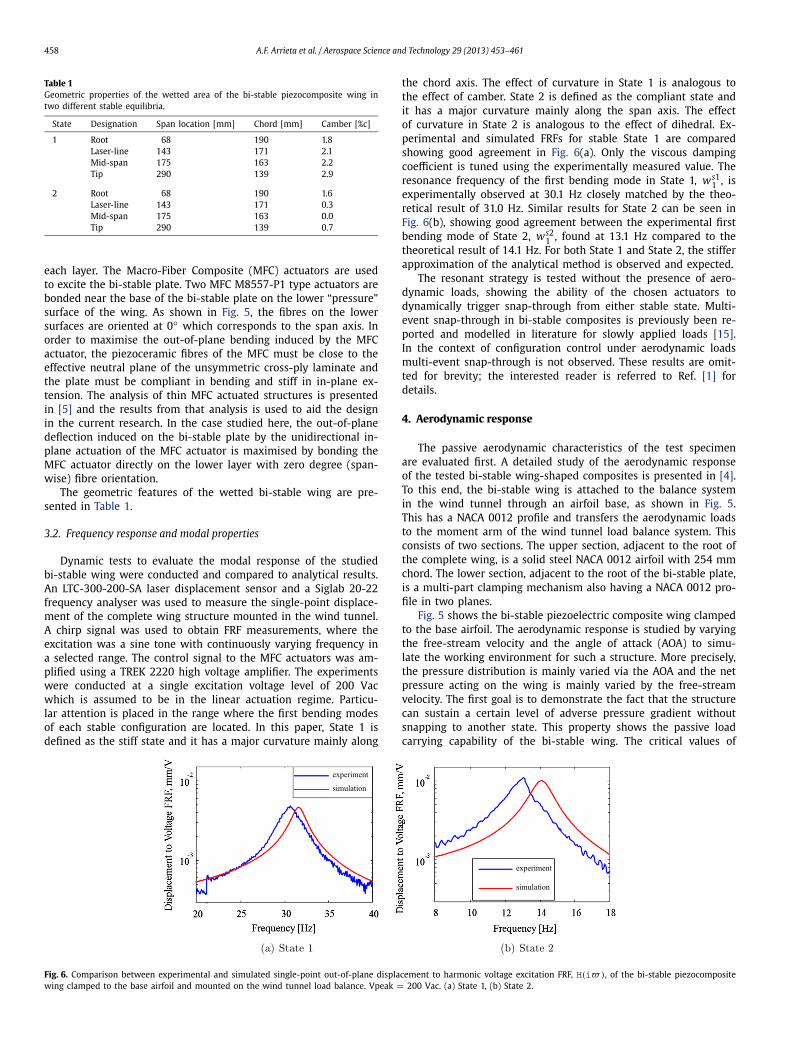
the chord axis. The effect of curvature in State 1 is analogous tothe effect of camber. State 2 is defined as the compliant state andit has a major curvature mainly along the span axis. The effectof curvature in State 2 is analogous to the effect of dihedral. Ex-perimental and simulated FRFs for stable State 1 are comparedshowing good agreement in Fig. 6(a). Only the viscous dampingcoefficient is tuned using the experimentally measured value. Theresonance frequency of the first bending mode in State 1, ws1
1 , isexperimentally observed at 30.1 Hz closely matched by the theo-retical result of 31.0 Hz. Similar results for State 2 can be seen inFig. 6(b), showing good agreement between the experimental firstbending mode of State 2, ws2
1 , found at 13.1 Hz compared to thetheoretical result of 14.1 Hz. For both State 1 and State 2, the stifferapproximation of the analytical method is observed and expected.
The resonant strategy is tested without the presence of aero-dynamic loads, showing the ability of the chosen actuators todynamically trigger snap-through from either stable state. Multi-event snap-through in bi-stable composites is previously been re-ported and modelled in literature for slowly applied loads [15].In the context of configuration control under aerodynamic loadsmulti-event snap-through is not observed. These results are omit-ted for brevity; the interested reader is referred to Ref. [1] fordetails.
4. Aerodynamic response
The passive aerodynamic characteristics of the test specimenare evaluated first. A detailed study of the aerodynamic responseof the tested bi-stable wing-shaped composites is presented in [4].To this end, the bi-stable wing is attached to the balance systemin the wind tunnel through an airfoil base, as shown in Fig. 5.This has a NACA 0012 profile and transfers the aerodynamic loadsto the moment arm of the wind tunnel load balance system. Thisconsists of two sections. The upper section, adjacent to the root ofthe complete wing, is a solid steel NACA 0012 airfoil with 254 mmchord. The lower section, adjacent to the root of the bi-stable plate,is a multi-part clamping mechanism also having a NACA 0012 pro-file in two planes.
Fig. 5 shows the bi-stable piezoelectric composite wing clampedto the base airfoil. The aerodynamic response is studied by varyingthe free-stream velocity and the angle of attack (AOA) to simu-late the working environment for such a structure. More precisely,the pressure distribution is mainly varied via the AOA and the netpressure acting on the wing is mainly varied by the free-streamvelocity. The first goal is to demonstrate the fact that the structurecan sustain a certain level of adverse pressure gradient withoutsnapping to another state. This property shows the passive loadcarrying capability of the bi-stable wing. The critical values of
Fig. 6. Comparison between experimental and simulated single-point out-of-plane displacement to harmonic voltage excitation FRF, H(i�), of the bi-stable piezocompositewing clamped to the base airfoil and mounted on the wind tunnel load balance. Vpeak = 200 Vac. (a) State 1, (b) State 2.

A.F. Arrieta et al. / Aerospace Science and Technology 29 (2013) 453–461 459
Fig. 7. Experimental (3D) aerodynamic response for active bi-stable wing to rota-tion angle, β , and free-stream velocity. Coloured arrows indicate the direction ofsnap-through for each AOA sweep. (a) Passive, (b) active with excitation at 13.0 Hz,800 Vac. (Colour online.)
snap-inducing velocity and AOA are key values in determining thepassive load carrying capability. It should be noted that the pitchangle, β , determined by the rotary table in the set-up, is selectedas the independent variable since the calculation of the geomet-ric AOA of the 3D structure in the wind tunnel is impractical withthe available sensors. First, the critical free-stream velocity and an-gle of attack that induce snap-through from State 1 to State 2 areexamined. These values are obtained through a set of AOA sweepsconducted in the range of 10 to 20 m/s nominal velocity values,where the velocity range is swept in 2.5 m/s steps. The AOA sweepis conducted, in both directions, in the range of −20◦ to +20◦varying the AOA in 0.5◦ steps. Snap-through may occur if the netpressure, primarily controlled by the free-stream velocity, is highenough in the AOA range that is examined; therefore a criticalfree-stream velocity also exists for a preselected range of AOA. Be-low the critical free-stream velocity, a state can be passively heldfor the entire AOA range that is of interest. Snap-through is in-duced by the dynamic pressure if the critical velocity is exceeded.Fig. 7(a) presents the aerodynamic response of the bi-stable plateat two different free-stream velocities where the AOA is first sweptup from −20◦ to +20◦ and swept back down to −20◦ . The wingis set at State 1 which is the favourable state at −20◦ AOA. Asnoted above, five velocity values are examined; however only twoimportant velocity values are presented. Fig. 7(a) also presents thetheoretical finite-wing lift curve for reference. A snap-through isnot observed for the complete AOA range, in both directions, at15.5 m/s and all other velocities below this critical value. Due tothe lack of aerodynamic hysteresis, the AOA up and down sweepsare averaged and presented as a single curve for the 15.5 m/s ve-locity test. In contrast, at 17.8 m/s, snap-through is observed inboth direction as expected – indicating that the critical velocity
value is in the range of 15.5 to 17.8 m/s. The path abcdefa is in-dicated in the figures to aid the discussion. An adverse pressuregradient sustained by the specimen develops from the angle atwhich the lift coefficient changes sign until the load carrying ca-pability of the specimen is lost when a snap-through is triggered.This can be observed by following the AOA sweeps in Fig. 7(a).
The second type of aerodynamic measurements on the bi-stable wing, following a similar experimental procedure as de-scribed above, is conducted to understand the actively inducedsnap-through that is caused by the MFC actuators. The goal here isto demonstrate that the structure can be made, effectively, monos-table against a certain level of adverse pressure gradient. Thisproperty shows the controllability of a desired state achieved withthe embedded MFC actuators under the presence of aerodynamicforces. The critical values of voltage excitation amplitude and fre-quency are key in determining the controllability property. First,a sinusoidal excitation with 800 Vac amplitude at 13.0 Hz is ap-plied which corresponds to the resonance frequency of State 2following the used resonant control strategy. This excitation causesthe wing to be effectively monostable for State 1. Fig. 7(b) presentsthe aerodynamic response of the bi-stable plate at three differentfree-stream velocities where the AOA is first swept up from −20◦to +20◦ and swept back down to −20◦ for the active case. Thepath abcdefa is indicated in the figures to aid the discussion. As inFig. 7(a), the wing is set at State 1 which is the favourable state at−20◦ AOA. A snap-through is not observed for the complete AOArange, in both directions, at 13.2 m/s and all other velocities belowthis critical velocity value. Due to the lack of aerodynamic hystere-sis, the AOA up and down sweeps are averaged and presented as asingle curve for the 13.2 m/s velocity test. In contrast, at 15.5 and17.8 m/s, snap-through is observed in both directions as expectedindicating that the critical velocity value is in the range of 13.2 to15.5 m/s. (Note: If a gust causes the wing to go from State 1 toState 2, snap-through from State 2 to State 1 is always guaranteedfor velocities below the critical velocity independent of the AOA.)In contrast to the passive structure, a dynamically induced snap-through from State 2 to State1 is observed near zero degree of themount angle where the pressure gradient is near neutral for thelower 15.5 m/s velocity (see the path ef in Fig. 7(b)). The snap-through occurs at −0.5◦ and 0.0◦ for the velocities of 17.8 and15.5 m/s respectively indicating that the dynamic excitation canachieve snap-through from State 2 to State 1 by tailoring the com-posite and optimising the distribution of actuation even against acertain level of adverse gradient.
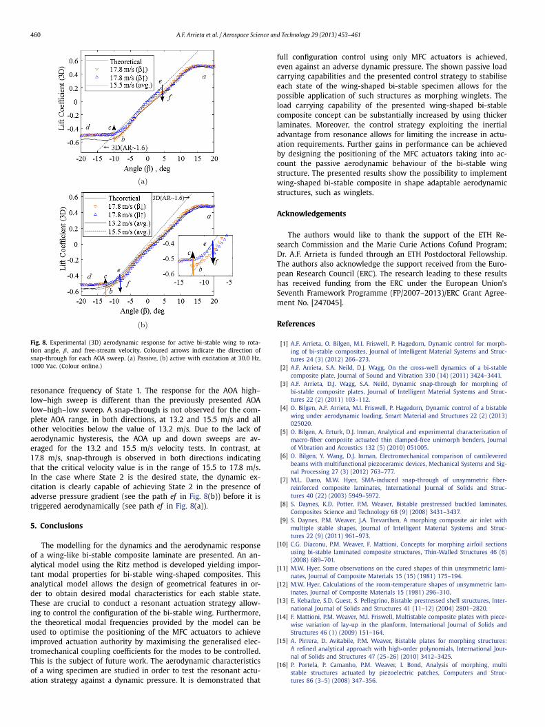
Similar results are obtained for the aerodynamic characteristicsand morphing control under the presence of flow induced pres-sure for State 2. Fig. 8(a) presents the aerodynamic response ofthe passive structure for free-stream and AOA sweeps first start-ing down from +20◦ to −20◦ and swept back up to +20◦ . Thewing is set at State 2 which is the favourable state at +20◦ AOAdue to pressure gradient. The response for the AOA high–low–highsweep is very similar to the previously presented AOA low–high–low sweep. A snap-through is not observed for the complete AOArange, in both directions, at 15.5 m/s and all other velocities belowthis critical value. Due to the lack of aerodynamic hysteresis, theAOA up and down sweeps are averaged and presented as a sin-gle curve for the 15.5 m/s velocity test. In contrast, at 17.8 m/s,snap-through is observed in both direction as expected, indicatingthat the critical velocity value is in the range of 15.5 to 17.8 m/s.For this case, the range of AOA for which an adverse pressure gra-dient develops is found as explained above. Fig. 8(b) presents thefree-stream and AOA sweeps of the dynamically excited bi-stableplate at three different free-stream velocities where the AOA isfirst swept down from +20◦ to −20◦ and swept back up to +20◦ .A sinusoidal excitation with 1000 Vac amplitude at 30.0 Hz and300 Vdc offset is applied – the excitation frequency is near the
460 A.F. Arrieta et al. / Aerospace Science and Technology 29 (2013) 453–461
Fig. 8. Experimental (3D) aerodynamic response for active bi-stable wing to rota-tion angle, β , and free-stream velocity. Coloured arrows indicate the direction ofsnap-through for each AOA sweep. (a) Passive, (b) active with excitation at 30.0 Hz,1000 Vac. (Colour online.)
resonance frequency of State 1. The response for the AOA high–low–high sweep is different than the previously presented AOAlow–high–low sweep. A snap-through is not observed for the com-plete AOA range, in both directions, at 13.2 and 15.5 m/s and allother velocities below the value of 13.2 m/s. Due to the lack ofaerodynamic hysteresis, the AOA up and down sweeps are av-eraged for the 13.2 and 15.5 m/s velocity tests. In contrast, at17.8 m/s, snap-through is observed in both directions indicatingthat the critical velocity value is in the range of 15.5 to 17.8 m/s.In the case where State 2 is the desired state, the dynamic ex-citation is clearly capable of achieving State 2 in the presence ofadverse pressure gradient (see the path ef in Fig. 8(b)) before it istriggered aerodynamically (see path ef in Fig. 8(a)).
5. Conclusions
The modelling for the dynamics and the aerodynamic responseof a wing-like bi-stable composite laminate are presented. An an-alytical model using the Ritz method is developed yielding impor-tant modal properties for bi-stable wing-shaped composites. Thisanalytical model allows the design of geometrical features in or-der to obtain desired modal characteristics for each stable state.These are crucial to conduct a resonant actuation strategy allow-ing to control the configuration of the bi-stable wing. Furthermore,the theoretical modal frequencies provided by the model can beused to optimise the positioning of the MFC actuators to achieveimproved actuation authority by maximising the generalised elec-tromechanical coupling coefficients for the modes to be controlled.This is the subject of future work. The aerodynamic characteristicsof a wing specimen are studied in order to test the resonant actu-ation strategy against a dynamic pressure. It is demonstrated that
full configuration control using only MFC actuators is achieved,even against an adverse dynamic pressure. The shown passive loadcarrying capabilities and the presented control strategy to stabiliseeach state of the wing-shaped bi-stable specimen allows for thepossible application of such structures as morphing winglets. Theload carrying capability of the presented wing-shaped bi-stablecomposite concept can be substantially increased by using thickerlaminates. Moreover, the control strategy exploiting the inertialadvantage from resonance allows for limiting the increase in actu-ation requirements. Further gains in performance can be achievedby designing the positioning of the MFC actuators taking into ac-count the passive aerodynamic behaviour of the bi-stable wingstructure. The presented results show the possibility to implementwing-shaped bi-stable composite in shape adaptable aerodynamicstructures, such as winglets.
Acknowledgements
The authors would like to thank the support of the ETH Re-search Commission and the Marie Curie Actions Cofund Program;Dr. A.F. Arrieta is funded through an ETH Postdoctoral Fellowship.The authors also acknowledge the support received from the Euro-pean Research Council (ERC). The research leading to these resultshas received funding from the ERC under the European Union’sSeventh Framework Programme (FP/2007–2013)/ERC Grant Agree-ment No. [247045].
References
[1] A.F. Arrieta, O. Bilgen, M.I. Friswell, P. Hagedorn, Dynamic control for morph-ing of bi-stable composites, Journal of Intelligent Material Systems and Struc-tures 24 (3) (2012) 266–273.
[2] A.F. Arrieta, S.A. Neild, D.J. Wagg, On the cross-well dynamics of a bi-stablecomposite plate, Journal of Sound and Vibration 330 (14) (2011) 3424–3441.
[3] A.F. Arrieta, D.J. Wagg, S.A. Neild, Dynamic snap-through for morphing ofbi-stable composite plates, Journal of Intelligent Material Systems and Struc-tures 22 (2) (2011) 103–112.
[4] O. Bilgen, A.F. Arrieta, M.I. Friswell, P. Hagedorn, Dynamic control of a bistablewing under aerodynamic loading, Smart Material and Structures 22 (2) (2013)025020.
[5] O. Bilgen, A. Erturk, D.J. Inman, Analytical and experimental characterization ofmacro-fiber composite actuated thin clamped-free unimorph benders, Journalof Vibration and Acoustics 132 (5) (2010) 051005.
[6] O. Bilgen, Y. Wang, D.J. Inman, Electromechanical comparison of cantileveredbeams with multifunctional piezoceramic devices, Mechanical Systems and Sig-nal Processing 27 (3) (2012) 763–777.
[7] M.L. Dano, M.W. Hyer, SMA-induced snap-through of unsymmetric fiber-reinforced composite laminates, International Journal of Solids and Struc-tures 40 (22) (2003) 5949–5972.
[8] S. Daynes, K.D. Potter, P.M. Weaver, Bistable prestressed buckled laminates,Composites Science and Technology 68 (9) (2008) 3431–3437.
[9] S. Daynes, P.M. Weaver, J.A. Trevarthen, A morphing composite air inlet withmultiple stable shapes, Journal of Intelligent Material Systems and Struc-tures 22 (9) (2011) 961–973.
[10] C.G. Diaconu, P.M. Weaver, F. Mattioni, Concepts for morphing airfoil sectionsusing bi-stable laminated composite structures, Thin-Walled Structures 46 (6)(2008) 689–701.
[11] M.W. Hyer, Some observations on the cured shapes of thin unsymmetric lami-nates, Journal of Composite Materials 15 (15) (1981) 175–194.
[12] M.W. Hyer, Calculations of the room-temperature shapes of unsymmetric lam-inates, Journal of Composite Materials 15 (1981) 296–310.
[13] E. Kebadze, S.D. Guest, S. Pellegrino, Bistable prestressed shell structures, Inter-national Journal of Solids and Structures 41 (11–12) (2004) 2801–2820.
[14] F. Mattioni, P.M. Weaver, M.I. Friswell, Multistable composite plates with piece-wise variation of lay-up in the planform, International Journal of Solids andStructures 46 (1) (2009) 151–164.
[15] A. Pirrera, D. Avitabile, P.M. Weaver, Bistable plates for morphing structures:A refined analytical approach with high-order polynomials, International Jour-nal of Solids and Structures 47 (25–26) (2010) 3412–3425.
[16] P. Portela, P. Camanho, P.M. Weaver, I. Bond, Analysis of morphing, multistable structures actuated by piezoelectric patches, Computers and Struc-tures 86 (3–5) (2008) 347–356.

A.F. Arrieta et al. / Aerospace Science and Technology 29 (2013) 453–461 461
[17] K.D. Potter, P.M. Weaver, A concept for the generation of out-of-plane distortionfrom tailored FRP laminates, Composites Part A: Applied Science and Manufac-turing 35 (12) (2004) 1353–1361.
[18] M.S. Qatu, Vibration of Laminated Shells and Plates, Elsevier Publishing Com-pany, 2004.
[19] M.R. Schultz, M.W. Hyer, Snap-through of unsymmetric cross-ply laminatesusing piezoceramic actuators, Journal of Intelligent Material Systems and Struc-tures 14 (12) (2003) 795–814.
[20] A. Senba, T. Ikeda, T. Ueda, A two-way morphing actuation of bi-stable com-posites with piezoelectric fibers, in: 51st AIAA/ASME/ASCE/AHS/ASC Structures,Structural Dynamics and Materials Conference, 12–15 April 2010, Orlando,Florida, USA, 2010.
[21] SGL Group: The Carbon Company, High-performance prepregs: Preimpregnatedproducts for fiber-reinforced composites, http://www.sglgroup.com, 2011.
[22] S.W. Tsai, H.T. Hahn, Introduction to Composite Materials, Technomic Publish-ing Company, Inc., 1980.
[23] D. Varelis, D.A. Saravanos, Coupled mechanics and finite element for non-linearlaminated piezoelectric shallow shells undergoing large displacements and ro-tations, International Journal for Numerical Methods in Engineering 66 (8)(2006) 1211–1233.
[24] D. Varelis, D.A. Saravanos, Non-linear coupled multi-field mechanics and finiteelement for active multi-stable thermal piezoelectric shells, International Jour-nal for Numerical Methods in Engineering 76 (1) (2008) 84–107.
[25] E. Ventsel, T. Krauthammer, Thin Plates and Shells: Theory: Analysis, and Ap-plications, Marcel Dekker, Inc., 2001.
[26] G.A. Vogl, M.W. Hyer, Natural vibration of unsymmetric cross-ply laminates,Journal of Sound and Vibration 20 (330) (2011) 4764–4779.
[27] W.K. Wilkie, R.G. Bryant, J.W. High, R.L. Fox, R.F. Hellbaum, A. Jalink Jr., B.D.Little, P.H. Mirick, Low-cost piezocomposite actuator for structural control ap-plications, in: 7th Annual International Symposium on Smart Structures andMaterials, March 5–9, 2000, Newport Beach, CA, USA, 2000.
Related Documents


![Aerospace Science and Technology...tests of a morphing wing built by using compliant mechanisms and piezoelectric actuators. In Nguyen et al. [6]the principles of aerodynamic shape](https://static.cupdf.com/doc/110x72/6100d1a0d699ac556a391526/aerospace-science-and-technology-tests-of-a-morphing-wing-built-by-using-compliant.jpg)