Joint Workshop of COST Actions TU0601 and E55 September 21-22 2009, Ljubljana, Slovenia 91 Modelling and analysis Leslaw Kwasniewski Warsaw University of Technology, Poland Bassam A. Izzuddin Imperial College London, United Kingdom Miguel Pereira Imperial College London, United Kingdom Carmen Bucur Technical University of Civil Engineering Bucharest, Romania Marian Gizejowski Warsaw University of Technology, Poland Summary The principal question for all modeling methods applied for evaluation of structural robustness is the extent of damage caused by a local failure initiated by a real infrequent event or notional column removal. This document discusses the modelling approaches that can be employed for the assessment of structural robustness, covering both simplified as well as detailed analysis techniques. Three methods are briefly presented: Design-Oriented Method, Detailed Nonlinear Dynamic Analysis, and Applied Element Method. The methods are based on different conceptual frameworks, apply different solution techniques and loading representations, and differ on how the materials and interactions are incorporated in the analysis. The first method is a design-oriented method, where the robustness limit state is based on avoidance of failure in the above floors following sudden column loss, and where a simplified dynamic assessment method is adopted thus avoiding the need for detailed nonlinear dynamic analysis. The second method is concerned with detailed nonlinear dynamic simulation of the structural response under extreme loading, including the effects of floor failure and impact. The third method, combining the features from finite element and discrete element methods, allow for tracking the structural collapse behaviour through all stages using a specially designed cubical element with a variety of inter-element connections. Keywords Progressive collapse, robustness, accidental loading, computer simulation, finite element analysis, design-oriented method, alternative load paths, connection resilience, connection redundancy, catenary action, arching action.

Welcome message from author
This document is posted to help you gain knowledge. Please leave a comment to let me know what you think about it! Share it to your friends and learn new things together.
Transcript
Joint Workshop of COST Actions TU0601 and E55 September 21-22 2009, Ljubljana, Slovenia
91
Modelling and analysis Leslaw Kwasniewski Warsaw University of Technology, Poland Bassam A. Izzuddin Imperial College London, United Kingdom Miguel Pereira Imperial College London, United Kingdom Carmen Bucur Technical University of Civil Engineering Bucharest, Romania Marian Gizejowski Warsaw University of Technology, Poland Summary
The principal question for all modeling methods applied for evaluation of structural robustness is the extent of damage caused by a local failure initiated by a real infrequent event or notional column removal. This document discusses the modelling approaches that can be employed for the assessment of structural robustness, covering both simplified as well as detailed analysis techniques. Three methods are briefly presented: Design-Oriented Method, Detailed Nonlinear Dynamic Analysis, and Applied Element Method. The methods are based on different conceptual frameworks, apply different solution techniques and loading representations, and differ on how the materials and interactions are incorporated in the analysis.
The first method is a design-oriented method, where the robustness limit state is based on avoidance of failure in the above floors following sudden column loss, and where a simplified dynamic assessment method is adopted thus avoiding the need for detailed nonlinear dynamic analysis. The second method is concerned with detailed nonlinear dynamic simulation of the structural response under extreme loading, including the effects of floor failure and impact. The third method, combining the features from finite element and discrete element methods, allow for tracking the structural collapse behaviour through all stages using a specially designed cubical element with a variety of inter-element connections.
Keywords
Progressive collapse, robustness, accidental loading, computer simulation, finite element analysis, design-oriented method, alternative load paths, connection resilience, connection redundancy, catenary action, arching action.
Modelling and analysis
92
Background / Introduction
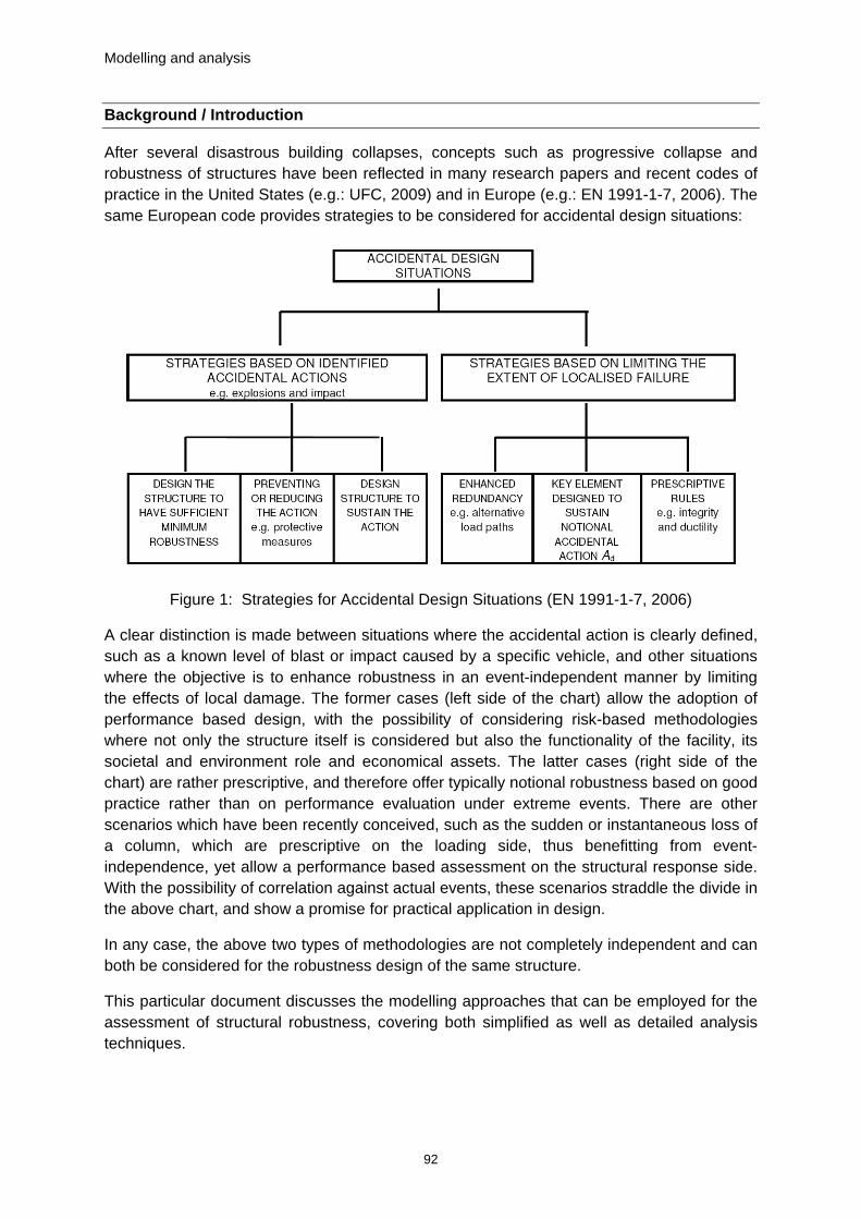
After several disastrous building collapses, concepts such as progressive collapse and robustness of structures have been reflected in many research papers and recent codes of practice in the United States (e.g.: UFC, 2009) and in Europe (e.g.: EN 1991-1-7, 2006). The same European code provides strategies to be considered for accidental design situations:
Figure 1: Strategies for Accidental Design Situations (EN 1991-1-7, 2006)
A clear distinction is made between situations where the accidental action is clearly defined, such as a known level of blast or impact caused by a specific vehicle, and other situations where the objective is to enhance robustness in an event-independent manner by limiting the effects of local damage. The former cases (left side of the chart) allow the adoption of performance based design, with the possibility of considering risk-based methodologies where not only the structure itself is considered but also the functionality of the facility, its societal and environment role and economical assets. The latter cases (right side of the chart) are rather prescriptive, and therefore offer typically notional robustness based on good practice rather than on performance evaluation under extreme events. There are other scenarios which have been recently conceived, such as the sudden or instantaneous loss of a column, which are prescriptive on the loading side, thus benefitting from event-independence, yet allow a performance based assessment on the structural response side. With the possibility of correlation against actual events, these scenarios straddle the divide in the above chart, and show a promise for practical application in design.
In any case, the above two types of methodologies are not completely independent and can both be considered for the robustness design of the same structure.
This particular document discusses the modelling approaches that can be employed for the assessment of structural robustness, covering both simplified as well as detailed analysis techniques.

Modelling and analysis
93
Problem statement / Key issues
The collapse of an entire structure or an essential part of it that is disproportionately large compared to the initiating local damage is considered a progressive collapse.
The most common design scenario is the event-independent sudden loss of a column or other vertical load bearing member (GSA, 2000), (UFC, 2009). The simplicity of this scenario allows the quantification of important issues as ductility, redundancy and energy absorption (Izzuddin et al., 2008), leading to a performance-based assessment even if the loading scenario itself is prescriptive.
Figure 2: Multi-storey building subject to sudden column loss (Izzuddin et al., 2008)
When the extreme event is well-defined, more detailed analysis methods, such as nonlinear dynamic finite element analysis, may be used. Such approaches additionally require knowledge of the structural configuration, material properties and the influence of elements typically not considered in the structural design, such as infill panels.
Analysis Methods
The GSA code (GSA, 2000) introduced a flow-chart procedure for determining if a specific building can be exempt from detailed consideration for progressive collapse. For non-exempt structures, finite element analyses at different levels of complexity are proposed. One can choose among linear or nonlinear, static or dynamic (time history), and between 2- and 3-dimensional (2D and 3D) analysis techniques (Herrle and McKay 2001). The GSA code limits the applicability of linear elastic static analysis procedures to buildings with a maximum of 10 stories above the ground. The nonlinear dynamic procedures are considered the most sophisticated and accurate structural assessment techniques. However, due to the complexity and inherent challenges, these procedures are less frequently used for progressive collapse analysis. The main difficulties are related to the numerical convergence problems, material models capturing inelastic properties and damage, modelling component
Modelling and analysis
94
disintegration caused by failure, requirements for mesh density to capture local effects, and the size of the FE models for large structures (e.g., multi-story buildings) which is associated with considerable computational demands. Other simplified and design-oriented methods have therefore emerged recently, where emphasis has been placed on capturing the main nonlinear dynamic phenomena involved in progressive collapse assessment within a computationally efficient framework that is viable for direct application in design.
The three methods presented hereafter are based on different conceptual frameworks. The first is a design-oriented method, where the robustness limit state is based on avoidance of failure in the above floors following sudden column loss, and where a simplified dynamic assessment method is adopted thus avoiding the need for detailed nonlinear dynamic analysis . The second method is concerned with detailed nonlinear dynamic simulation of the structural response under extreme loading, including the effects of floor failure and impact. The third method, combining the features from finite element and discrete element methods, allow for tracking the structural collapse behaviour through all stages using a specially designed cubical element with a variety of inter-element connections.
A Design-Oriented Method
A simplified approach has been proposed by Izzuddin et al. (2008) for progressive collapse assessment of multi-storey building structures considering sudden column loss as a design scenario, which offers a quantitative framework for the consideration of such important issues as ductility, redundancy and energy absorption. This approach requires only the nonlinear static response under gravity loading of the structure excluding the removed column, with dynamic effects evaluated in a simplified, yet reasonably accurate, manner.
Accordingly, the proposed assessment framework utilises three main stages:
i. nonlinear static response of the damaged structure under gravity loading, considering the beneficial effects of such nonlinear phenomena as compressive arching and catenary actions;
ii. simplified dynamic assessment to establish the maximum dynamic response under sudden column loss; and,
iii. ductility assessment of the joints by comparing maximum ductility demands to ductility supply.
This simplified assessment framework may be applied at the overall structural level and, importantly, at various sub-structural levels, according to the required modelling detail and the feasibility of model reduction (Izzuddin et al., 2008).
Nonlinear static response
The sudden removal of the bottom column (Figure 3(a)) is similar in effect to sudden application of the gravity load (P0) on the same structure, particularly when the structure sustains significant deformations as a result. This sudden application of gravity loading leads to dynamic effects, where the ductility demands for all deformation states up to the maximum dynamic response (Figure 3(b)) must be met in order to avoid failure. A simplifying feature of

Modelling and analysis
95
this framework is that the maximum dynamic response can be estimated with reasonable accuracy from the nonlinear static response under amplified gravity loading (λdP0), as illustrated in (Figure 3(c)), thus removing the need for detailed nonlinear dynamic analysis. This bears some similarity to simplified equivalent single-degree-of-freedom (SDOF) models for extreme dynamic loading (e.g. blast), where the deformation modes under static loading are used as a basis for estimating the dynamic response. Therefore, the nonlinear static response of the structure, excluding the lost column, is required under gravity loading that is varied according to a scaling factor (P = λP0), where a typical response is shown in Figure 3(d).
(a) Sudden column loss (b) Maximum dynamic response (c) Amplified static loading
(d) Characteristic nonlinear static response under proportional load (P = λP0)
Figure 3: Sudden column removal using amplified static loading (Izzuddin et al., 2008)
Simplified dynamic assessment
Under a sudden column loss scenario, a typical building structure exhibits a highly nonlinear dynamic response, and thus any assessment of ductility demands should consider the maximum dynamic response of the structure. In this respect, the previous UFC code in the USA (DoD, 2005) recommended the use of nonlinear dynamic analysis for the damaged structure, though this is overly complicated for practical application in structural design. To address this issue, an alternative simplified approach has been allowed by the latest UFC code (DoD, 2009), which allows a nonlinear static assessment coupled with the use of dynamic amplification factors for gravity loading above the damaged column that reduce with the levels of ductility in the structure. However, recent work by Izzuddin & Nethercot (2009) has shown that this approach is not sufficiently rational and could lead to designs for robustness that are seriously unsafe.

Modelling and analysis
96
Addressing such shortcomings, a rational simplified treatment was proposed by Izzuddin et al. (2008), the so-called ductility-centred approach, which determines the maximum dynamic response based on principles of energy balance. This approach considers that in the initial stages of the dynamic response, the gravity load exceeds the static structural resistance, and the differential work done over the incremental deformations is transformed into additional kinetic energy, thus leading to increasing velocities. As the deformations increase, the static resistance exceeds the gravity loading, and the differential energy absorbed accounts for a reduction in the kinetic energy, thus leading to decreasing velocities. Considering a response dominated by a single deformation mode, the maximum dynamic response is achieved when the kinetic energy is reduced back to zero, and hence when the work done by the gravity loads becomes identical to the energy absorbed by the structure. This allows the maximum dynamic displacement to be obtained from energy balance as illustrated in Figures 4(a-b) for two levels of gravity loading, leading to the notion of a pseudo-static response depicting the variation of maximum dynamic displacement with applied gravity loading as shown in Figure 4(c).
The above simplified dynamic assessment approach provides clear computational benefits in comparison with detailed nonlinear dynamic analysis, aids in the understanding of the dynamic response characteristics under sudden column loss, and can be easily applied at various levels of structural idealisation (Izzuddin et al., 2008).
(a) Dynamic response (P = λ1P0) (b) Dynamic response (P = λ2P0) (c) Pseudo-static response
Figure 4: Simplified dynamic assessment and pseudo-static response (Izzuddin et al., 2008)
Another aspect of dynamic assessment is the treatment of the effects of material rate-sensitivity, where an extension of the simplified dynamic assessment procedure has been recently proposed towards this end (Pereira & Izzuddin, 2009). Using this approach, it was shown that material rate-sensitivity for steel-framed building can improve resistance to progressive collapse by around 25%.
Ductility assessment
This is the final stage of assessment where the maximum dynamic displacement (ud) under the applied gravity loading (P = P0) is compared to the ductility limit (uf) to establish the limit state.
In determining the ductility limit, the variation of connection deformation demands with ud is considered, and uf is established as the minimum value of ud for which the deformation demand becomes equal to the supply in any of the connections. Although such a criterion is

Modelling and analysis
97
based on first failure of at a connection component, the simplified approach can also deal with multiple failures (Izzuddin, 2008).
Measure of structural robustness
Commonly advocated indicators are inadequate on their own as measures of structural robustness, particularly since all of these can have positive as well as negative influences (Izzuddin et al., 2008). For sudden column loss scenarios, the comparison of the system pseudo-static capacity (Pf) against the applied gravity loading (P0) establishes the robustness limit state and provides a single measure of robustness including the combined influence of common indicators, such as ductility, redundancy and energy absorption capacity.
Detailed Nonlinear Dynamic Analysis
For all approaches applied for evaluation of structural robustness, the principal question is the extent of damage caused by a local failure initiated by a real infrequent event or notional column removal. The common factor for such investigations is that an analysis is conducted beyond the point where the loading reaches its extreme level and often the structure loses its stability and collapses. To fulfill all such requirements, often the researchers have to turn toward three dimensional (3D), nonlinear dynamic analyses. As a consequence, so-called computer simulations cover the post-buckling behavior or development of failure mechanisms. A computer model is the numerical, discrete representation of the mathematical model, which, in turn, usually attempts to characterize a physical problem. In engineering and research practice, a computer model is developed, solved, and analyzed with the aid of computer programs that can be advanced, general purpose, commercial software, or specialized unique programs developed by academia. In both cases, the majority of today’s computer programs, dedicated to structural analysis, are based on the Finite Element (FE) Method.
Static versus Dynamic
Depending on how time is treated in the analysis, we can choose among dynamic, quasi-static, and strictly static approaches. The loss of stability is usually a dynamic process, and therefore should be directly traced using the most general, dynamic approach. In structural stability, it is considered that for conservative systems (i.e., elastic structures with ideal constraints and subject to conservative loading) the simpler, static approach leads to the same results as the more complicated dynamic approach (Ziegler, 1977). This consideration is commonly extended to nonlinear structures subject to conservative loading.
In the dynamic analysis, the inertia effects have to be included, usually accompanied by damping forces and the strain rate dependence of the material behavior. This explicit time dependence requires calculating of time derivatives with respect to the actual, physical time. In the static analyses, the inertia effects are ignored. In the strictly static approaches, the actual time is replaced by a history-like parameter used to measure incrementally the analysis’s progress. For quasi-static problems, the real-time measure can be present to capture phenomena such as creep or temperature deformation, but the inertia effects are still ignored. Nonlinearity and discontinuity cause convergence problems that are less severe

Modelling and analysis
98
in the dynamic (with both implicit and explicit time integration) due to the stabilizing effect of the inertia forces (Belytschko et al. 2000).
Explicit versus Implicit Time Integration
Implicit dynamic analysis (using implicit time integrators) is dedicated for structural problems described by (Belytschko et al., 2000) as inertial problems where stress wave propagation and related effects are not important. For such problems, the response time is relatively long compared to the time required for a stress wave to traverse the structure. When the response time sought is short and the wave effects are important, the time step must be very small, and more appropriate solution methods are those based on the explicit time integration. Figure 5 shows an example of implicit dynamic analysis using the ABAQUS program for the large-scale model of Chorzow Trade Hall, which collapsed under snow loading (Lutomirski et al., 2007).
Figure 5: Failure mechanism of roof structure in Chorzow Trade Hall simulated using dynamic approach with implicit time integration (Lutomirski et al., 2007)
The explicit scheme belongs to purely incremental methods and is applicable only to formally dynamic problems. The incremental solution methods dominate incremental-iterative methods, especially for problems experiencing rough nonlinearities, which involve inequality constraints such as contact or friction. In the explicit methods, the equations of motion are usually solved using the central difference method with very small time steps determined by the highest frequency of the linearized system (Hallquist ,2009). The codes based on the explicit time integration are dedicated to dynamic transient problems and have proved to be especially effective when large deformations grow rapidly. Contrary to the implicit methods, the explicit time integration cycle is computationally much less expensive as there are no iterations and only one diagonal matrix needs to be inverted. However, this approach requires a much larger number of calculation cycles. With a time step of the order of microseconds, even a few seconds of a typical simulated event require millions of calculation cycles and substantial calculation time. Additionally, the extension of the simulated time can lead to numerical instabilities such as hourglass modes (Hallquist, 2009). The explicit method is simple, easy to implement, and very effective; it rarely aborts due to failure of the numerical algorithm, which is quite often in the problem for implicit methods. Even though the dynamic response, obtained using the explicit method, can be different from the static, implicit outcome, it should be remembered that for many cases the dynamic behaviour is more accurate. It is especially true for the post-critical phase, which is usually by nature

Modelling and analysis
99
dynamic. Also, the FE dynamic calculation is more convergent due to the stabilizing effect of inertia effects (see Figure 6). To increase the stability of the dynamic equilibrium, viscous global damping can be added in dynamic analysis.
t = 3 s t = 9 s t = 10 s
Figure 6: Example of transient dynamic simulation for global FE models of a multistory building (Kwasniewski, 2009)
Element Erosion and Tied Nodes Failure
Depending on the type of loading (e.g., explosion) and type of material, several criteria for material failure can be formulated in terms of strains or stresses (Hallquist 2006). For example the criterion limiting the effective plastic strain is commonly used for metals. For brittle materials such as concrete, a combination of several criteria can be applied independently, and once any one of them is satisfied, the element is deleted from the calculation.
Once, one of the applied criteria of failure is satisfied for a finite element, the element is deleted (eroded) from further calculations. In this way, the separation of the model components can be simulated. However, when there are high stresses, the rapid removal of an element can interfere with the local balance of forces and cause computational instabilities. A better strategy is to include in the material model reduction (softening) of the element stiffness due to damage and to allow for the substantial decrease of stresses prior to the element erosion. The removal of an element is often necessary to avoid numerical instabilities caused by the extensive deformation of such elements. Element erosion has also some disadvantages. The removal of many elements from the calculation affects the energy balance and the total mass of the model. For coarse mesh densities, large portions of the model can disappear unnaturally.
Another option called “tied nodes” possible in some of the programs (e.g., LSDYNA) allows for separation of the failed elements at the common nodes. Mesh with merged sheared nodes can be automatically replaced during pre-processing with tied nodes, separate for each element but with the same coordinates. The massless ties between the nodes are released when the prescribed failure criterion is reached. In this way, finite elements can separate along the edges without element erosion. This concept is also applied in the Applied Element Method.
Verification and Validation
Modelling and analysis
100
The complexity of full-scale numerical models analyzed within the inelastic range, including instability and failure, raises questions about the predictive capabilities. Verification and validation (V&V) are recognized as the primary method for evaluating the confidence of computer simulations (Oberkampf et al. 2004). Verification uses a comparison of computational solutions with highly accurate (analytical or numerical) benchmark solutions among them, whereas validation compares the numerical solution with the experimental data. There are three main objectives for verification and validation: to detect and separate the model’s significant discrepancies, to remove and reduce removable and unavoidable errors, and to evaluate the uncertainties in the results.
Applied Element Method
The Applied Element Method (AEM) combines features from finite element and discrete element methods, (Tagel-Din and Rahman, 2006). The main advantage of this method is that it can track the structural collapse behaviour passing through all stages of the application of loads, elastic stage, crack initiation and propagation in tension-weak materials, reinforcement yielding, element separation, element collision (contact), and collision with the ground and with adjacent structures.
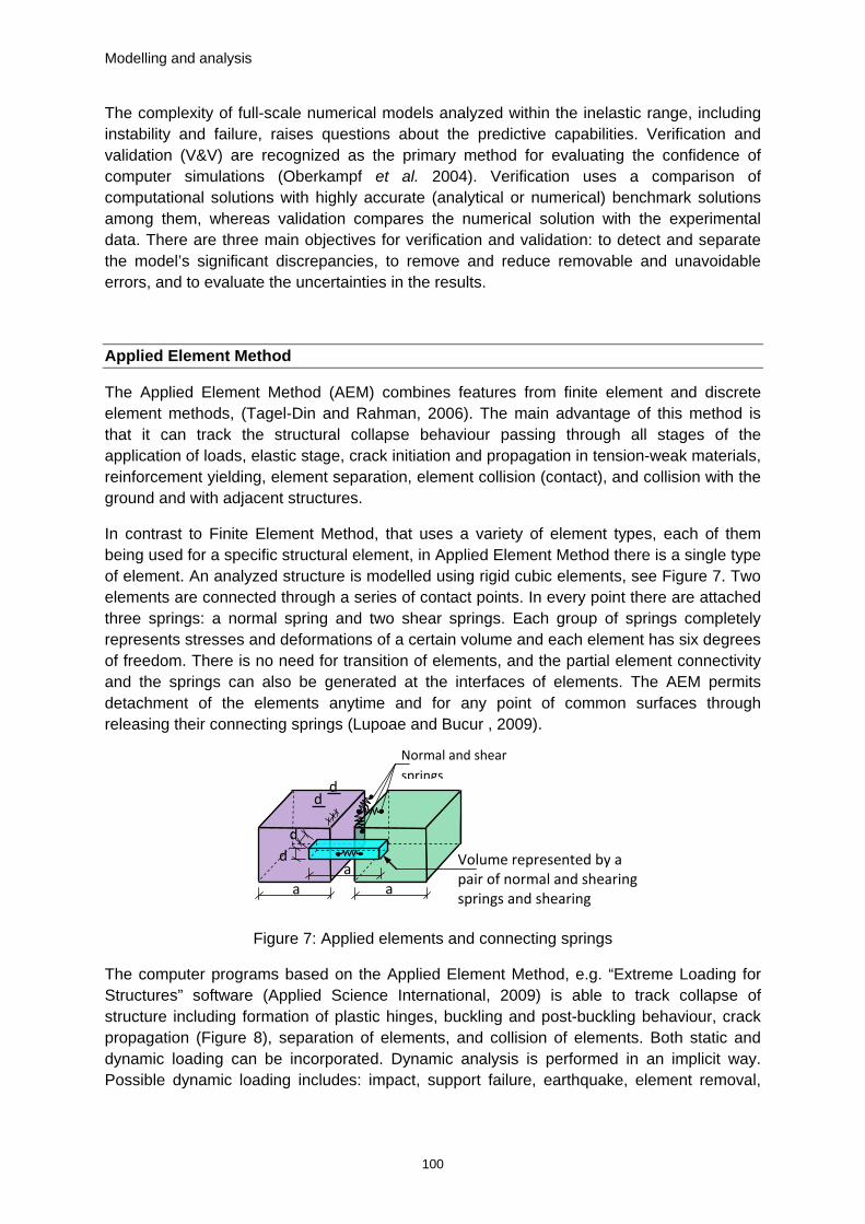
In contrast to Finite Element Method, that uses a variety of element types, each of them being used for a specific structural element, in Applied Element Method there is a single type of element. An analyzed structure is modelled using rigid cubic elements, see Figure 7. Two elements are connected through a series of contact points. In every point there are attached three springs: a normal spring and two shear springs. Each group of springs completely represents stresses and deformations of a certain volume and each element has six degrees of freedom. There is no need for transition of elements, and the partial element connectivity and the springs can also be generated at the interfaces of elements. The AEM permits detachment of the elements anytime and for any point of common surfaces through releasing their connecting springs (Lupoae and Bucur , 2009).
Figure 7: Applied elements and connecting springs
The computer programs based on the Applied Element Method, e.g. “Extreme Loading for Structures” software (Applied Science International, 2009) is able to track collapse of structure including formation of plastic hinges, buckling and post-buckling behaviour, crack propagation (Figure 8), separation of elements, and collision of elements. Both static and dynamic loading can be incorporated. Dynamic analysis is performed in an implicit way. Possible dynamic loading includes: impact, support failure, earthquake, element removal,
Normal and shear springs
a a
a
d d
d
d
Volume represented by a pair of normal and shearing springs and shearing
Modelling and analysis
101
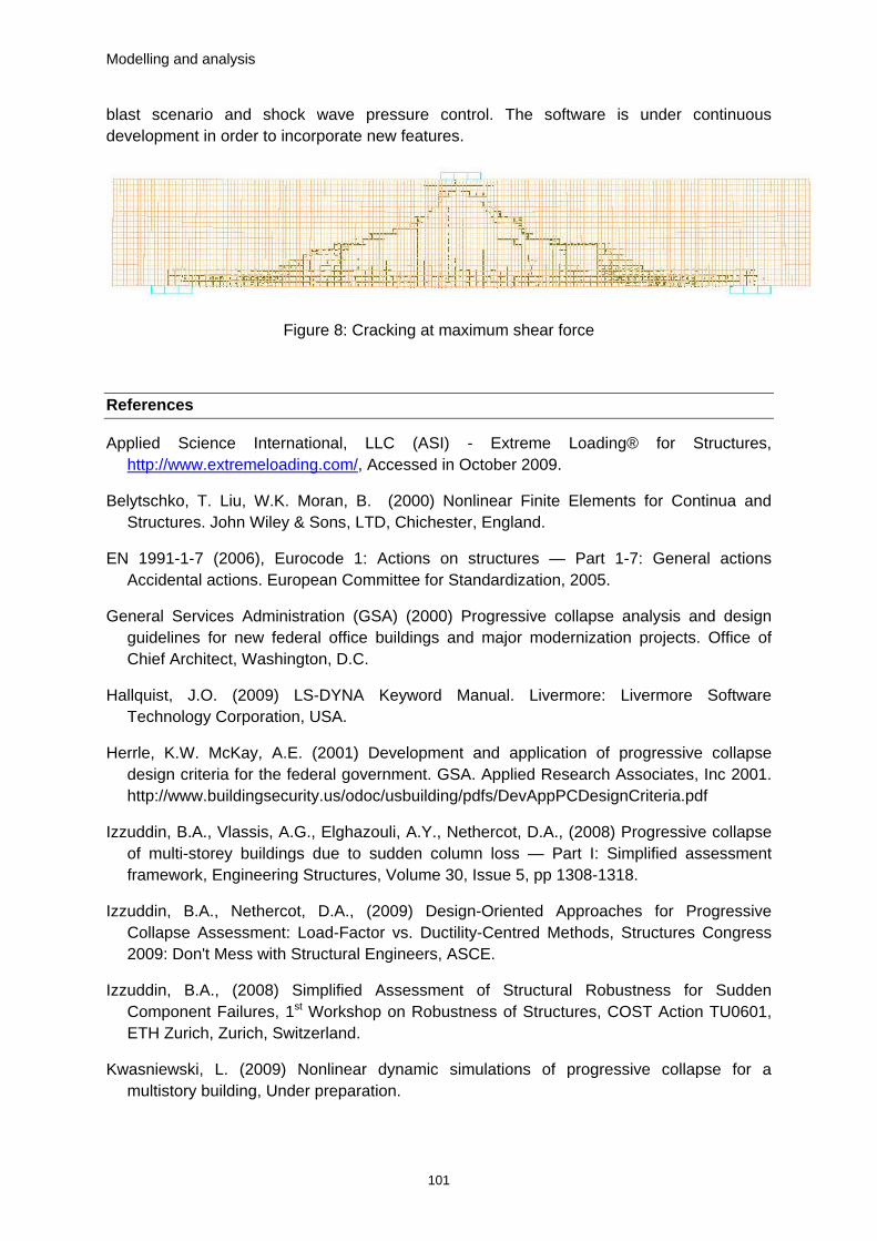
blast scenario and shock wave pressure control. The software is under continuous development in order to incorporate new features.
Figure 8: Cracking at maximum shear force
References
Applied Science International, LLC (ASI) - Extreme Loading® for Structures, http://www.extremeloading.com/, Accessed in October 2009.
Belytschko, T. Liu, W.K. Moran, B. (2000) Nonlinear Finite Elements for Continua and Structures. John Wiley & Sons, LTD, Chichester, England.
EN 1991-1-7 (2006), Eurocode 1: Actions on structures — Part 1-7: General actions Accidental actions. European Committee for Standardization, 2005.
General Services Administration (GSA) (2000) Progressive collapse analysis and design guidelines for new federal office buildings and major modernization projects. Office of Chief Architect, Washington, D.C.
Hallquist, J.O. (2009) LS-DYNA Keyword Manual. Livermore: Livermore Software Technology Corporation, USA.
Herrle, K.W. McKay, A.E. (2001) Development and application of progressive collapse design criteria for the federal government. GSA. Applied Research Associates, Inc 2001. http://www.buildingsecurity.us/odoc/usbuilding/pdfs/DevAppPCDesignCriteria.pdf
Izzuddin, B.A., Vlassis, A.G., Elghazouli, A.Y., Nethercot, D.A., (2008) Progressive collapse of multi-storey buildings due to sudden column loss — Part I: Simplified assessment framework, Engineering Structures, Volume 30, Issue 5, pp 1308-1318.
Izzuddin, B.A., Nethercot, D.A., (2009) Design-Oriented Approaches for Progressive Collapse Assessment: Load-Factor vs. Ductility-Centred Methods, Structures Congress 2009: Don't Mess with Structural Engineers, ASCE.
Izzuddin, B.A., (2008) Simplified Assessment of Structural Robustness for Sudden Component Failures, 1st Workshop on Robustness of Structures, COST Action TU0601, ETH Zurich, Zurich, Switzerland.
Kwasniewski, L. (2009) Nonlinear dynamic simulations of progressive collapse for a multistory building, Under preparation.

Modelling and analysis
102
LUPOAE M. and BUCUR C. (2009) Use of Applied Element Method to Simulate the Collapse of a Building – Academy of Technical Sciences Commission of Acoustics of Romanian Academy Annual Symposium of the Institute of Solid Mechanics - SISOM 2009 - Session 1 System Dynamics and continuum mechanics, http://www.extremeloading.com/Publications.aspx
Lutomirski, S. Kwasniewski, L. Kozyra, Z. Winnicki, A. (2007) Failure analysis of Chorzów Trade Hall roof collapse. 23rd Konferencja Naukowo-Techniczna “Awarie budowlane” (Structural Failures). in Polish. Szczecin – Miedzyzdroje, Poland, pp. 631-639.
Oberkampf, W.L. Trucano, T.G. Hirsch, C. (2004) Verification, validation, and predictive capability in computational engi-neering and physics. Appl. Mech. Rev. 57 (5), 345–384.
Pereira, M., Izzuddin, B.A., (2009) Assessment of Progressive Collapse in Multi-Storey Buildings – Influence of Material Rate Sensitivity, Proceedings of the 6th International Conference on Advances in Steel Structures, ICASS’09, Hong Kong.
TAGEL-DIN H., RAHMAN N. A. (2006) - The Applied Element Method: The Ultimate Analysis of Progressive Collapse, Structure Magazine, No 4, April 2006, pp 30-33.
U.S. Department of Defense (DoD) (2005) Unified facilities criteria (UFC), Design of buildings to resist progressive collapse. Department of Defense, UFC 4-023-03, U.S. Army Corps of Engineering, Washington, D.C., 31.
U.S. Department of Defense (DoD) (2009) Unified facilities criteria (UFC), Design of buildings to resist progressive collapse. Department of Defense, UFC 4-023-03, U.S. Army Corps of Engineering, Washington, D.C., 31.
U.S. Department of Defense (DoD) (2009) Unified facilities criteria (UFC), DoD minimum antiterrorism standards for buildings. Department of Defense, UFC 4-010-01, U.S. Army Corps of Engineering, Washington, D.C., 31.
Ziegler, H. (1977) Principles of Structural Stability. Basel und Stuttgart: Birkhauser Verlag
Related Documents


