International Journal of Structural Stability and Dynamics Vol. 2, No. 4 (2002) 431–456 c World Scientific Publishing Company MODELING WITH INCREASED EFFICIENCY AND VERSATILITY FOR FLEXURAL-TORSIONAL BUCKLING OF UNSYMMETRICAL THIN-WALLED STRUCTURES S. S. MARZOUK * , A. S. GENDY † and S. N. MIKHAIEL ‡ Department of Structural Engineering, Faculty of Engineering, Cairo University, Egypt A. F. SALEEB § Department of Civil Engineering, The University of Akron, Akron, Ohio, OH 44325-3905, USA [email protected] Received 17 October 2001 Accepted 17 July 2002 Aiming at the performance-enhancement in coarse mesh modeling, we utilize a number of closed form solutions of a class of torsionally loaded thin-walled bars to formulate a two-noded element for spatial buckling analysis. The key in this relates to the use of the “exact” solution for the displacement fields (as oppose to the more conventional finite element approach where polynomial/Lagrangian-type interpolation is employed). That is, in addition to the well known “exact” solution for the coupled flexure/transverse- shear problem, we utilize a new “exact” solution for the more difficult case of coupled system of differential equations governing a torsionally loaded thin-walled beam using the higher-order theories of non-uniform twist/bi-moment with coupled warping-shear deformations. For the linear analysis, convergence and accuracy study indicated that the proposed model to be rapidly convergent, stable and computationally efficient; i.e. one element is sufficient to exactly represent an end loaded part of the beam. Such model has been extended to account for nonlinear analysis, in particular, the flexural torsional buckling of thin-walled structures. To this end, the effect of finite rotations in space is accounted for as per the modern theories of spatial buckling, resulting in second-order accurate geometric stiffness matrices. Compared with the classical theory of thin-walled structures, the present approach is more general in that all significant modes of stretch- ing, bending, shear (due to both flexure and torsional/warping), torsion, and warping are accounted for. The inclusion of non-uniform torsion is accomplished through adoption of the principle sectorial area. This requires incorporation of a warping degree of freedom in addition to the conventional six degrees of freedom at each node. The element is derived for general cross sections including the Wagner-effect contributions. The model’s prop- erties and performance, particularly with regard to the resulting (significant) improve- ments in mesh accuracy, are assessed in a fairly complete set of numerical simulations. Keywords : Buckling; thin-walled sections; closed form solution; coarse/mesh accuracy; warping/shear effects; Wagner-effect; mono-symmetric section. * Graduate student. † Associate Professor. ‡ Professor. § Professor. 431

Welcome message from author
This document is posted to help you gain knowledge. Please leave a comment to let me know what you think about it! Share it to your friends and learn new things together.
Transcript
December 10, 2002 18:0 WSPC/165-IJSSD 00065
International Journal of Structural Stability and DynamicsVol. 2, No. 4 (2002) 431–456c© World Scientific Publishing Company
MODELING WITH INCREASED EFFICIENCY ANDVERSATILITY FOR FLEXURAL-TORSIONAL BUCKLING OF
UNSYMMETRICAL THIN-WALLED STRUCTURES
S. S. MARZOUK∗, A. S. GENDY† and S. N. MIKHAIEL‡
Department of Structural Engineering, Faculty of Engineering, Cairo University, Egypt
A. F. SALEEB§
Department of Civil Engineering, The University of Akron,Akron, Ohio, OH 44325-3905, USA
Received 17 October 2001Accepted 17 July 2002
Aiming at the performance-enhancement in coarse mesh modeling, we utilize a numberof closed form solutions of a class of torsionally loaded thin-walled bars to formulate atwo-noded element for spatial buckling analysis. The key in this relates to the use of the“exact” solution for the displacement fields (as oppose to the more conventional finiteelement approach where polynomial/Lagrangian-type interpolation is employed). Thatis, in addition to the well known “exact” solution for the coupled flexure/transverse-shear problem, we utilize a new “exact” solution for the more difficult case of coupledsystem of differential equations governing a torsionally loaded thin-walled beam usingthe higher-order theories of non-uniform twist/bi-moment with coupled warping-sheardeformations. For the linear analysis, convergence and accuracy study indicated that theproposed model to be rapidly convergent, stable and computationally efficient; i.e. oneelement is sufficient to exactly represent an end loaded part of the beam. Such modelhas been extended to account for nonlinear analysis, in particular, the flexural torsionalbuckling of thin-walled structures. To this end, the effect of finite rotations in space isaccounted for as per the modern theories of spatial buckling, resulting in second-orderaccurate geometric stiffness matrices. Compared with the classical theory of thin-walledstructures, the present approach is more general in that all significant modes of stretch-ing, bending, shear (due to both flexure and torsional/warping), torsion, and warping areaccounted for. The inclusion of non-uniform torsion is accomplished through adoption ofthe principle sectorial area. This requires incorporation of a warping degree of freedom inaddition to the conventional six degrees of freedom at each node. The element is derivedfor general cross sections including the Wagner-effect contributions. The model’s prop-erties and performance, particularly with regard to the resulting (significant) improve-ments in mesh accuracy, are assessed in a fairly complete set of numerical simulations.
Keywords: Buckling; thin-walled sections; closed form solution; coarse/mesh accuracy;warping/shear effects; Wagner-effect; mono-symmetric section.
∗Graduate student.†Associate Professor.‡Professor.§Professor.
431
December 10, 2002 18:0 WSPC/165-IJSSD 00065
432 S. S. Marzouk et al.
1. Introduction
The past few years have witnessed research efforts directed towards the development
of effective nonlinear models for thin-walled beams of different configurations and
cross-sectional shapes. Currently, a large number of theoretical studies as well as
numerical simulations utilizing the finite element exist for nonlinear analysis of one-
dimensional structures. However, for the most part, these studies have focused on
cases involving solid cross-sections (i.e. no warping). In this, three main approaches
being identified for analysis: Total Lagrangian, Updated Lagrangian and Eurlian. In
the former approach system variables are referred to the initial configuration, which
leads to complex strain-displacement relationships.1 In the second approach, system
quantities are referred incrementally to the last known equilibrium configuration,2–6
which results in simpler strain-displacement relationships. In the latter approach,
quantities are referred to the current unknown configuration.7–9 Adopting this
Eurlian finite element approach with rotation parameters having the traditional
meaning of non-commutative orthogonal transformations in Euclidean space, the
“consistently-linearized” weak (variational) form derives was shown9 to generally
exhibit a non-symmetric geometric stiffness, even for conservative loading. On the
other hand, investigations for more general problems with arbitrary thin-walled
sections (i.e. involving the effect of non-uniform or warping torsional behavior) are
rather limited. Further, most developed models of this latter case include a simplest
form of approximation (shape) functions for warping/torsional deformations.
From both theoretical and numerical stand points; a number of fundamentals
issues are called for the “consistent” development of general finite element
models for spatial stability analysis of thin-walled elastic beams. Among many
others, the most important issues reported in the literature are as follows:
(1) Careful selection of the shape (interpolation) functions to account for the
coupled stretching-flexural-torsional response, and to avoid the so-called locking
phenomena10,11 for the limited case of thin beams when the shear deformations are
considered in the formulation. (2) Effect of finite nodal rotations on the deriva-
tion of the second-order-accurate geometric stiffness components (e.g. Refs. 2,
12 and 13) to model the complete spectrum of the significant instability modes.
Details of studies aiming at item (1) constitute our first major objective here,
i.e. through the development of new “exact” sets of displacement fields for coupled
stretch/flexure/shear/torsion/warping. In particular, a novel one-dimensional for-
mulation for large displacement analysis has been developed, based on the updated
Lagrange approach. Interpolation functions for torsional/warping displacements are
obtained from the solution of the governing differential equations of a torsionally
loaded thin-walled beam with warping restraint. Shear deformations associated with
shear/flexure as well as torsion/warping modes are accounted for. The formulation
is valid for both open and closed sections; and this is accomplished by utilizing the
kinematical description accounting for both flexural and torsional warping effects.
Handling of issues pertinent to item (2) follows along the well known lines of
modern theories of spatial buckling; i.e. see pioneering works in Ref. 14; see also
December 10, 2002 18:0 WSPC/165-IJSSD 00065
Flexural-Torsional Buckling of Unsymmetrical Thin-Walled Structures 433
Ref. 3 for detailed results, motivations and significance of these issues in the context
of traditional finite element interpolation functions. Only an outline for these parts
is given here for completeness.
Our second major objective is to report on the results of an extensive set of
problems including linear as well as nonlinear elastic stability. The results obtained
by the proposed model are compared to those produced by the hybrid/mixed finite
element model (early studies by the author3) to evaluate and assess its performance.
The solutions obtained by the new developed model was found to be very rapidly
convergent, stable and computationally efficient.
In an out-line-form, the remainder of this paper includes the following sections:
weak (variational) formulation, governing equations for thin-walled structures,
finite element formulation, verification examples and applications, followed by
conclusions. For convenience, tensors as well as their counterpart vector/tensor
representations are used interchangeably in all subsequent sections.
2. Weak Formulation-General Form of Nonlinear Analysis
As a starting point, the incremental form of the displacements based varia-
tional principle in the step-by-step, non-linear solution has been utilized. For the
general continuum case, this takes the following form in the updated Lagrangian
description, with the configuration at time “t” as reference
∆π(u) = π(t+ ∆t)− π(t) (1a)
∆π =
∫v
[1
2∆eT c∆e + σT∆e
]dv −∆W (1b)
where
∆e = ∆ε(linear) + ∆η(non-linear) (1c)
∆εi,j =1
2(ui,j + uj,i) ; ∆ηi,j =
1
2uk,iuk,j , (1d)
are respectively, geometric (from displacement derivatives) Green–Lagrange strain
increments; c the material stiffness; ∆σ = c∆e the stress increments, σ the true
(Cauchy) stress (initial stresses); and ∆W the work of prescribed surface/body
forces. Equation (1d) gives the tensor components for the linear and non-linear
(geometric strains) ∆ε and ∆η in terms of the incremental displacement field
u (with the reference to rectangular cartesian co-ordinates). It can be noted
that the use is made of the summation convention over repeated indices, and
the “comma” subscript indicates the differentiation with respect to the spatial
co-ordinate following.
The above expression can be now specialized and used as a basis for general non-
linear (incremental) analysis of thin-walled structures, i.e. accounting for the effect
of initial pre-buckling displacements, instability states, as well as post-buckling
December 10, 2002 18:0 WSPC/165-IJSSD 00065
434 S. S. Marzouk et al.
response. However, restricting the scope of the paper to linearized buckling Eq. (1a)
can be now written as:
∆π = π(buckling state)− π(initial state) . (2)
Once the finite element discretizations are introduced for incremental displacement
u in ∆e, the stationarity condition; i.e. δ∆π = 0, with respect to displacement
parameters will the yield the governing stiffness equations. The first term in Eq. (1b)
yields the element linear stiffness; whereas the geometric stiffness results from the
contribution of non-linear (quadratic) strains in the second term. Specific forms of
the various arrays for thin-walled element are given later.
3. Governing Equations for Thin-Walled Structures
3.1. Kinematics
The classical theory of thin-walled structures with arbitrary cross-section is based
on the classical work of Timoshenko15 on shear-deformation effects and Vlasov16 on
out-of-plane warping of cross-sections of beams. The following basic assumptions
are utilized in the geometric/kinematic descriptions:
(A1): Undistorted cross-section.
(A2): Small strains but large displacements and cross-section rotations.
(A3): Small warping displacement relative to typical lateral beam dimensions.
(A4): Elastic, isotropic and homogenous material.
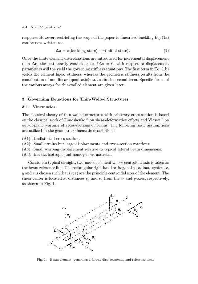
Consider a typical straight, two-noded, element whose centroidal axis is taken as
the beam reference line. The rectangular right hand orthogonal coordinate system x,
y and z is chosen such that (y, z) are the principle centroidal axes of the element. The
shear center is located at distances ey and ez from the z- and y-axes, respectively,
as shown in Fig. 1.
Fig. 1. Beam element; generalized forces, displacements, and reference axes.
December 10, 2002 18:0 WSPC/165-IJSSD 00065
Flexural-Torsional Buckling of Unsymmetrical Thin-Walled Structures 435
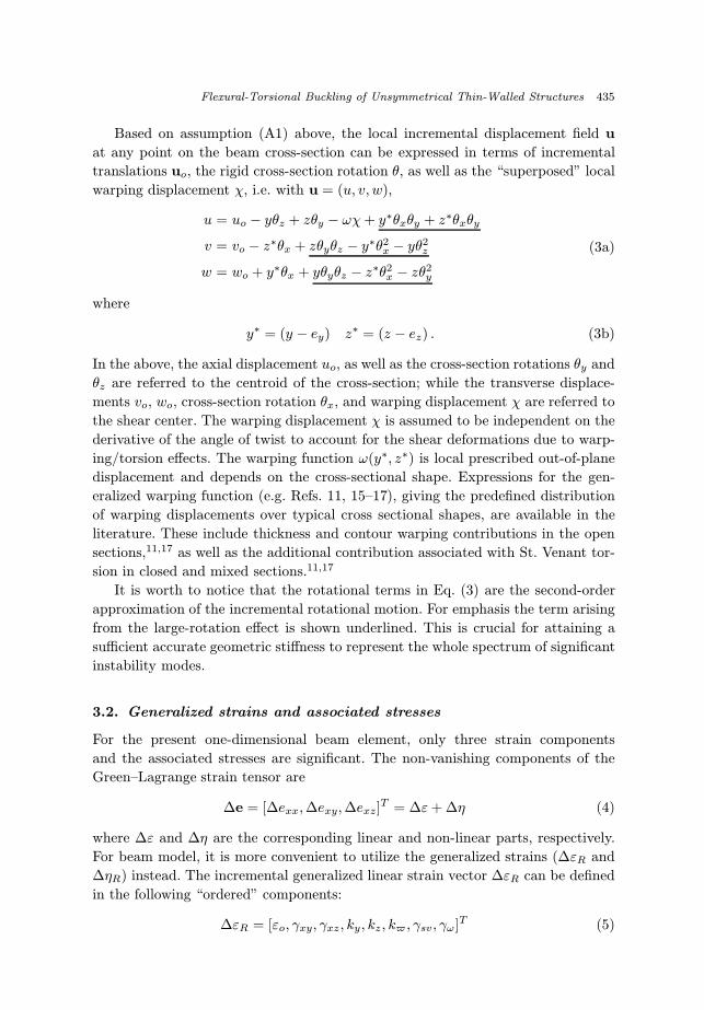
Based on assumption (A1) above, the local incremental displacement field u
at any point on the beam cross-section can be expressed in terms of incremental
translations uo, the rigid cross-section rotation θ, as well as the “superposed” local
warping displacement χ, i.e. with u = (u, v, w),
u = uo − yθz + zθy − ωχ+ y∗θxθy + z∗θxθy
v = vo − z∗θx + zθyθz − y∗θ2x − yθ2
z
w = wo + y∗θx + yθyθz − z∗θ2x − zθ2
y
(3a)
where
y∗ = (y − ey) z∗ = (z − ez) . (3b)
In the above, the axial displacement uo, as well as the cross-section rotations θy and
θz are referred to the centroid of the cross-section; while the transverse displace-
ments vo, wo, cross-section rotation θx, and warping displacement χ are referred to
the shear center. The warping displacement χ is assumed to be independent on the
derivative of the angle of twist to account for the shear deformations due to warp-
ing/torsion effects. The warping function ω(y∗, z∗) is local prescribed out-of-plane
displacement and depends on the cross-sectional shape. Expressions for the gen-
eralized warping function (e.g. Refs. 11, 15–17), giving the predefined distribution
of warping displacements over typical cross sectional shapes, are available in the
literature. These include thickness and contour warping contributions in the open
sections,11,17 as well as the additional contribution associated with St. Venant tor-
sion in closed and mixed sections.11,17
It is worth to notice that the rotational terms in Eq. (3) are the second-order
approximation of the incremental rotational motion. For emphasis the term arising
from the large-rotation effect is shown underlined. This is crucial for attaining a
sufficient accurate geometric stiffness to represent the whole spectrum of significant
instability modes.
3.2. Generalized strains and associated stresses
For the present one-dimensional beam element, only three strain components
and the associated stresses are significant. The non-vanishing components of the
Green–Lagrange strain tensor are
∆e = [∆exx,∆exy,∆exz]T = ∆ε+ ∆η (4)
where ∆ε and ∆η are the corresponding linear and non-linear parts, respectively.
For beam model, it is more convenient to utilize the generalized strains (∆εR and
∆ηR) instead. The incremental generalized linear strain vector ∆εR can be defined
in the following “ordered” components:
∆εR = [εo, γxy, γxz, ky, kz, k$, γsv, γω]T (5)
December 10, 2002 18:0 WSPC/165-IJSSD 00065
436 S. S. Marzouk et al.
where
εo = u′o ; γxy = v′o − θz ; γxz = w′o + θy
ky = θ′y ; kz = θ′z ; k$ = χ′
γsv = θ′x ; γ$ = θ′x − χ
(6)
in which the prime indicates the differentiation w.r.t. the coordinate x. In the
above, εo is the axial stretch, γxy and γxz the (average) transverse shear strains
due to flexure; ky , kz and kω the bending and warping curvatures; and γsv and γωthe torsional shear strains associated with the St. Venant (uniform torsion) and
warping (non-uniform torsion) response components, respectively.
Similarly, one can write the generalized non-linear strain components, ∆ηR, as
∆ηR = [ηo, ηxy, ηxz, kNy , k
Nz , k
Nw , ηsv, η$]T (7)
where
ηo =1
2[u′2o + v
′2o + w
′2o + r2
gθ′2x + 2(ezv
′o − eyw′o)θ′x
−ey(θ′xθy + θxθ′y)− ez(θ′xθz + θxθ
′z)] (8a)
ηxy = −u′oθz + w′oθx +1
2θxθy (8b)
ηxz = u′oθy − v′oθx +1
2θxθz (8c)
kNy = u′oθ′y − v′oθ′x − ezθ′2x +
1
2(θ′xθz + θxθ
′z) (8d)
kNz = u′oθ′z − w′oθ′x + eyθ
′2x −
1
2(θ′xθy + θxθ
′y) (8e)
kNw = u′oχ′ (8f)
ηsv =1
2(θ′yθz − θyθ′z) (8g)
η$ = ηsv − u′oχ (8h)
with
r2g =
[Iy + Iz
A+ (e2
y + e2z)
]. (8i)
The fourth item in Eq. (8a) is often referred to as “uniform stretching” Wagner
(effect) parameter. The underlined terms in Eq. (8) arising from the effect of large
rotation [see Eq. (3)] are indicated here for further discussions.
The incremental stress resultant ∆σR can be defined as
∆σR = [∆Fx,∆Fy,∆Fz ,∆My,∆Mz,∆M$,∆Tsv,∆T$]T (9)
December 10, 2002 18:0 WSPC/165-IJSSD 00065
Flexural-Torsional Buckling of Unsymmetrical Thin-Walled Structures 437
in which ∆Fx, ∆Fy and ∆Fz are the normal and shear force components; ∆My,
∆Mz, ∆Mω the bending and bi-moments; ∆Tsv and ∆Tω the contribution to the
twist moment ∆Mx, i.e. the St. Venant and warping ( or “bitwist”) torsional mo-
ments, respectively. It is worthy to mention that the shear forces, torsional moments,
and bi-moment are referred to the shear center; while the normal force, and bending
moments are referred to the centroid of the section. Such incremental components
can be defined as
∆Fx =
∫A
∆σxxdA ; ∆Fy =
∫A
∆σxydA ; ∆Fz =
∫A
∆σxzdA
∆My =
∫A
∆σxxzdA ; ∆Mz = −∫A
∆σxxydA ; ∆Mω = −∫A
∆σxxωdA
∆Tsv =
∫A
[∆σxy(z∗ + ω,y) + ∆σxz(y∗ − ω,Z)]dA ;
∆Tω =
∫A
[(∆σxyω,y + ∆σxzω,z)]dA . (10)
Similar expressions are used for the eight components of the total generalized stress
vector of the initially stressed beam, but with the increments ∆σ replaced with their
“total” counterparts σ.
Using the above equations; i.e. Eqs. (1c), (3), (6) and (10), one can arrive at the
“resultant-type” constitutive expression; i.e.
∆σ = C∆εR (11)
where the symmetric (8 × 8) matrix C is the spatial elasticity tensor, i.e. section-
rigidities (or moduli) matrix; i.e.
C = Diag.[EA,GAsy , GAsz , EIy, EIz , EIω , GJ,G(Ip − J)] (12)
where Diag.[ ] denotes a diagonal matrix. In addition to the well known axial,
shear and bending stiffness coefficients in the first five diagonal terms in Eq. (12)
(Asi = αAi, for i = y, z are the flexural shear correction factors2,3,11), the following
St. Venant and warping torsion rigidities are defined as in Refs. 15–17
J =
∫A
[(y∗ − ω,z)2 + (z∗ + ω,y)2]dA , Ip =
∫A
ρ2dA , Iω =
∫A
ω2dA (13)
where ρ is the perpendicular distance from the shear center to the tangent to the
sectorial profile at considered point.11
4. Finite Element Formulation
4.1. Interpolation functions for displacements
For the present two-node one dimensional element, designated here as DEB2, the
incremental displacement fields, u, within the element are approximated in terms
December 10, 2002 18:0 WSPC/165-IJSSD 00065
438 S. S. Marzouk et al.
of the incremental nodal displacements, q, as
u = [h1 h2]qu ;{v
θz
}=
[h3 h4 h5 h6
h7 h8 h9 h10
]qvθz ;{
θxχ
}=
[h11 h12 h13 h14
h15 h16 h17 h18
]qθxχ
(14)
where hi is the ith shape function, qu, qvθz , and qθxχ are the column vectors contain
the nodal displacements for stretching, shear/flexure, and torsion/warping respec-
tively. The axial displacement is interpolated utilizing the linear shape function,
i.e.
h1 = 1− ξ ; h2 = ξ (15a)
with
ξ = x/L . (15b)
The Hermit shape functions are used to interpolate the transverse displacement
v and associated rotation θz as
h3 =1
1 + φz[1− 3ξ2 + 2ξ3 + φz(1− ξ)] ;
h4 =L
1 + φz
[ξ − 2ξ2 + ξ3 +
1
2φzξ(1− ξ)
] (16a)
h5 =1
1 + φz[3ξ2 − 2ξ3 + φzξ] ; h6 =
L
1 + φz
[−ξ2 + ξ3 − 1
2φzξ(1 − ξ)
](16b)
h7 =1
1 + φz[−6ξ2 + 6ξ3] ; h8 =
1
1 + φz[1− 4ξ + 3ξ2 − φz(1− ξ)] (16c)
h9 =L
1 + φz[6ξ2 − 6ξ3] ; h10 =
1
1 + φz[−2ξ + 3ξ2 + φzξ] (16d)
where φz is the contribution of the shear deformation effect for flexure in the x-y
plane and is defined as
φz =12EIzGAsyL2
. (17)
Similar expression to that in the second term of Eq. (14) can be utilized for
the transverse displacement w and its associated rotation θy. In this case, the
interpolation functions are identical to those in Eq. (16) except the two expressions
of h8 and h10 must multiply by negative sign.
The interpolation functions for the twist rotation and warping displacement are
obtained from the solution of the differential equations of the tortionally loaded
thin-walled beam with warping restraint. Such governing differential equations of
December 10, 2002 18:0 WSPC/165-IJSSD 00065
Flexural-Torsional Buckling of Unsymmetrical Thin-Walled Structures 439
equilibrium for thin-walled beam under uniform distributed torsional moment mx
can be written as
GJθ′′x +G(Ip − J)(θ′′z − χ′) = −mx (18a)
EIwχ′′ +G(Ip − J)(θ′x − χ) = 0 . (18b)
The above-coupled equations are generally applicable to all thin-walled beams of
open, closed and multi-cellular cross-sections.
Differentiating Eq. (18a) twice and Eq. (18b) once w.r.t beam axis x, one can
get
G(Ip − J)χ′′′ = GIpθIVx +
d2mx
dx2(19a)
EIwχ′′′ +G(Ip − J)(θ′′x − χ′) = 0 . (19b)
Substituting from Eq. (19a) into Eq. (19b) and employing Eq. (18a), one can arrive
at
θIVx − k2θ′′x +1
GIp
d2mx
dx2− k2
GJmx = 0 (20)
where
k2 =GJ
EIw
(Ip − J)
Ip. (21)
The above factor k is a measure of the rate of decay of torsional warping effects
along the girder and away from the point of warping restraint. Substituting from
Eq. (18a) into Eq. (19b) yields
χ′′′ − k2(χ′ +
mx
GJ
)= 0 . (22)
Equations (20) and (22) are the two differential equations for a torsionally loaded
thin walled beam with warping restraint. Assuming that the beam has no dis-
tributed twist (i.e. mx = 0), the solution of Eq. (20) can be obtained in the form
θx = D1 +D2x+D3 sinh kx+D4 cosh kx (23)
where Di, (i = 1, 2, 3, 4) are constants to be determinate. The warping displacement
χ can now be obtained in terms of the rotation, θx, from Eq. (18a) as
χ′ =Ip
(Ip − J)θ′′x . (24)
Employing Eq. (23) into Eq. (24) and integrate, one can arrive at an expression
of warping displacement as
χ =GJ
EIwk[D3 cosh kx+D4 sinh kx+D5] . (25)
December 10, 2002 18:0 WSPC/165-IJSSD 00065
440 S. S. Marzouk et al.
In the above, D5 is another constant of integration. Substituting from Eq. (23) and
Eq. (25) into Eq. (18b) and collecting terms, one can write the constant D5 in terms
of D2 as
D5 =EIw
GJkD2 . (26)
Substituting from Eq. (26) into Eq. (25), one can write the warping displacement,
in addition to the rotation θx, in terms of the generalized coordinates Di, (i =
1, 2, 3, 4), in a matrix form as{θxχ
}=
[1 x sinh kx cosh kx
0 1 ζ cosh kx ζ sinh kx
]D (27)
where
D = [D1 D2 D3 D4]T ; ζ =GJ
EIwk. (28)
The generalized coordinates Di have to be expressed in terms of the nodal displace-
ment θx1 , χ1, θx2 , χ2 by substituting the following conditions in Eqs. (27):
at node 1 x = 0 θx = θx1 and χ = χ1
at node 2 x = L θx = θx2 and χ = χ2(29)
that gives
qθxχ = MD (30)
where
M =
1 0 0 1
0 1 ζ 0
1 L sinh kL cosh kL
0 1 ζ cosh kL ζ sinh kL
. (31)
Solving Eq. (30) in D and substituting into Eq. (27), one can arrive at the ex-
pressions for the interpolation functions for the torsion/warping displacements
(i.e. hi(i = 11→ 18) in Eq. (14)) as
h11 = 1 +δ
αλI+R ∃ ; h12 = ξL +
1
α
(δL
λ− 1
ζ
)I+
(RL− δ
ζαλ
)∃ (32a)
h13 = − δ
αλI−R ∃ ; h14 =
1
ζαI+
δ
ζαλ∃ (32b)
h15 = −ζRI+δ
αλζ sinh kx ; h16 = 1.0− βI+ Ψ sinh kx (32c)
h17 = ζRI− ζ
αλδ sinh kx ; h18 = − δ
αλI+
1
αsinh kx (32d)
December 10, 2002 18:0 WSPC/165-IJSSD 00065
Flexural-Torsional Buckling of Unsymmetrical Thin-Walled Structures 441
where
I = coshkx− 1 ; ∃ = ξx− sinhkx (33a)
δ = coshkL− 1 ; λ = sinh kL− ζL (33b)
α = sinhkL− δ2
λ; R =
1
λ
(1 +
δ2
αλ
)(33c)
β =1
λ
(Lζ +
Lζ
αλδ2 − δ
α
); Ψ =
1
α
(ζLδ
λ− 1
). (33d)
4.2. Element stiffness equations
Specializing for the present beam case, a “consistently linearized” expression for
a displacement-based variational principle can be typically be written as (using
updated Lagrange approach)
∆π =
∫l
[1
2∆εTRC∆εR + σTR∆ηR
]dx+ UguNL −∆W̄ (34a)
where
UguNL =
∫l
[∫A
(σxx −
Fx
A
)(y2 + z2)dA
]θ′2x dx (34b)
∆W̄ = ∆W −∫l
σTR∆εRdx . (34c)
In the above, the integration is carried out over the total length, l, of the beam
and all stress/strain vectors are expressed in the resultant form, with ordering of
components as in Eq. (5). The term in Eq. (34) accounts for the so-called Wagner
effect associated with the torsional warping actions in beam with unsymmetrical
sections16 (i.e. it vanishes for the bi-symmetric case). The first parenthetical term in
Eq. (34b) is obtained from the well-known expression (i.e.My
Iyz−Mz
Izy− Mω
Iωω). The
second term in the bracket of Eq. (34a) gives the geometric stiffness for bi-symmetric
case, which can be expand as∫l
σTR∆ηRdx =
∫l
[Fxηo + Fyηxy + Fzηxz +MyκNy +Mzκ
Nz
+MωκNω + Tsvηsv + Tωηω ]dx (35)
where the generalized incremental non-linear strains are given in Eq. (8), and the
associated internal stress resultants (at the initial state) can be obtained from the
linear analysis as (providing that the beam is unloaded between its two nodes)
Fx = Fx2 ; Fy = Fy2 ; Fz = Fz2 (36a)
Mi = −Mi1
(1− x
l
)+Mi2
x
l, (i = y, z) (36b)
December 10, 2002 18:0 WSPC/165-IJSSD 00065
442 S. S. Marzouk et al.
Mω = Mω1
(cosh kl
sinhklsinh kx− cosh kx
)+Mω2
sinh kx
sinh kl(36c)
Tω = Tω1
(cosh kl
sinhklsinh kx− cosh kx
)+ Tω2
sinh kx
sinh kl(36d)
Mx = Tsv2 + Tω2 (36e)
where ( . )1 and ( . )2 are the quantities ( . ) calculated at the first and the second
nodes, respectively.
The external potential ωW in Eq. (34c), for conservative end loads, is given by
∆W =2∑i=1
|Q̄q|x=xi (37a)
where (see Fig. 1)
Q̄ = [Fx, Fy, Fz,Mx,My,Mz,Mω]T ; q = [u, v, w, θx, θy, θz, χ]T (37b)
are the nodal forces and the displacements, respectively. The over-bar in Eq. (37a)
signifies a prescribed quantity. Note that the kinematic boundary conditions here
correspond simply to specifying any of the components in q.
Substituting Eq. (14) into Eqs. (6) and (8), then using them into linearized form
of variational principle (i.e. Eq. (34), and invoking the stationary condition w.r.t.
the nodal parameters, q, leads to the desired stiffness relationships
(KL + KNL) · q = Q̄−QI (38)
where
KL =
∫l
BTCBdx ; QI =
∫l
BTσRdx (39a)
1
2qTKNLq = the second term in Eq. (34a) ; εR = Bq . (39b)
Here, KL is the element linear stiffness, KNL its geometric stiffness, QI the inter-
nal force vector and B the strain-displacement operator obtained from Eq. (6). Once
assembled for entire structure, the global stiffness provides the following criterion
for linearized buckling, i.e.
‖KL + KNL‖ = 0 (39c)
where ‖ · ‖ stands for the determinant, and where KNL is now calculated for pre-
defined initial stress distribution corresponding to the pre-buckling loading state
(load factors). The lowest eigen-value and corresponding mode will then define the
critical state.
December 10, 2002 18:0 WSPC/165-IJSSD 00065
Flexural-Torsional Buckling of Unsymmetrical Thin-Walled Structures 443
5. Verification Examples and Applications
The performance of the developed model, DEB2, is examined in a number of
numerical simulations for linear as well as nonlinear analyses. For linear cases,
we focus on several applications involving complex torsional-warping responses,
aiming at demonstrating superior accuracy of DEB2 (e.g. compared to more con-
ventional finite elements in the recent literature [e.g., Refs. 11 and 14). For the
nonlinear problems one, attention is given to spatial buckling of beams and frames,
in particular, the lateral torsional buckling of beams with symmetrical as well as
mono-symmetrical cross sections. Effect of large rotation in space on the nonlinear
of kinematic relations is also investigated. Attention in these applications is given
to the fact that the nonlinear response of the new element DEB2 maintained its
superiority (relative to other conventional finite elements) in the nonlinear regimes.
The present results are compared with a number of well-documented solutions
available in the literature. For better appreciation of these comparisons, we also
show results from other state-of-art elements; i.e. the mixed element HMB2 in
Ref. 3, noting additionally that this element is very comparable to the recent
reduced-integration elements in Ref. 14.
5.1. Linear-analysis results
A number of test problems are considered in this section to assess the perfor-
mance of the developed element in the linear analysis. These include a variety of
thin-walled open as well as closed beams under different flexural-torsional load-
ing conditions. Special emphasis is given to the warping shear effect. Results that
are always obtained utilizing a single DEB2 element for an end loaded part of
beam are compared with those obtained with HMB2 element developed earlier
by the authors11 (i.e. based on the traditional polynomial-type finite element
interpolation). Note that for the special case of linear flexure/torsion problems,
one can easily show that the mixed element in Ref. 11 is equivalent to the reduced
integration, displacement-type element in Ref. 14. Also comparisons are made with
analytical (when it is available) as well as other numerical solutions.
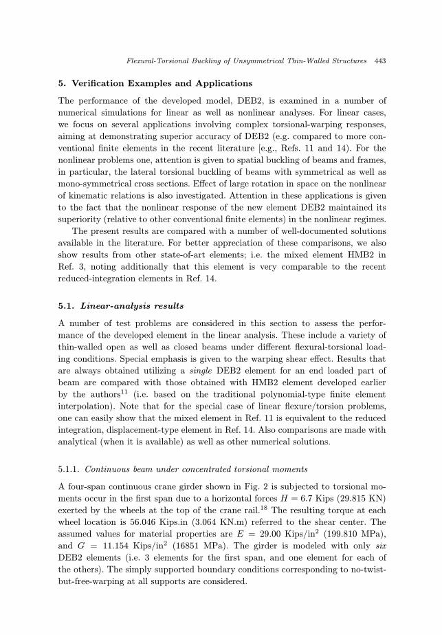
5.1.1. Continuous beam under concentrated torsional moments
A four-span continuous crane girder shown in Fig. 2 is subjected to torsional mo-
ments occur in the first span due to a horizontal forces H = 6.7 Kips (29.815 KN)
exerted by the wheels at the top of the crane rail.18 The resulting torque at each
wheel location is 56.046 Kips.in (3.064 KN.m) referred to the shear center. The
assumed values for material properties are E = 29.00 Kips/in2 (199.810 MPa),
and G = 11.154 Kips/in2 (16851 MPa). The girder is modeled with only six
DEB2 elements (i.e. 3 elements for the first span, and one element for each of
the others). The simply supported boundary conditions corresponding to no-twist-
but-free-warping at all supports are considered.
December 10, 2002 18:0 WSPC/165-IJSSD 00065
444 S. S. Marzouk et al.
Fig. 2. A torsionally loaded continuous girder.
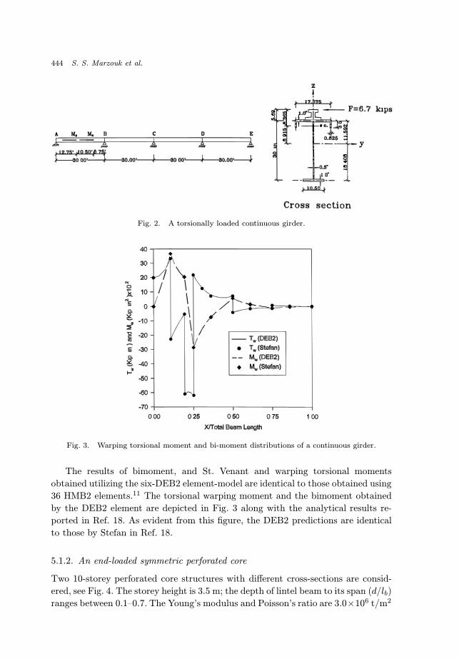
Fig. 3. Warping torsional moment and bi-moment distributions of a continuous girder.
The results of bimoment, and St. Venant and warping torsional moments
obtained utilizing the six-DEB2 element-model are identical to those obtained using
36 HMB2 elements.11 The torsional warping moment and the bimoment obtained
by the DEB2 element are depicted in Fig. 3 along with the analytical results re-
ported in Ref. 18. As evident from this figure, the DEB2 predictions are identical
to those by Stefan in Ref. 18.
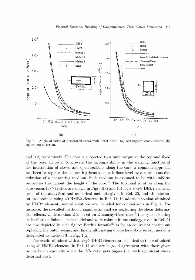
5.1.2. An end-loaded symmetric perforated core
Two 10-storey perforated core structures with different cross-sections are consid-
ered, see Fig. 4. The storey height is 3.5 m; the depth of lintel beam to its span (d/lb)
ranges between 0.1–0.7. The Young’s modulus and Poisson’s ratio are 3.0×10⁶ t/m2
December 10, 2002 18:0 WSPC/165-IJSSD 00065
Flexural-Torsional Buckling of Unsymmetrical Thin-Walled Structures 445
(a) (b)
Fig. 4. Angle of twist of perforated cores with lintel beam; (a) rectangular cross section. (b)square cross section.
and 0.2, respectively. The core is subjected to a unit torque at the top and fixed
at the base. In order to prevent the incompatibility in the warping function at
the intersection of closed and open sections along the core, a common approach
has been to replace the connecting beams at each floor level by a continuous dis-
tribution of a connecting medium. Such medium is assumed to be with uniform
properties throughout the height of the core.19 The torsional rotation along the
core versus (d/lb) ratios are shown in Figs. 4(a) and (b) for a single DEB2 element,
some of the analytical and numerical methods given in Ref. 20, and also the so-
lution obtained using 40 HMB2 elements in Ref. 11. In addition to that obtained
by HMB2 element, several solutions are included for comparisons in Fig. 4. For
instance, the so-called method 1 signifies an analysis neglecting the shear deforma-
tion effects, while method 2 is based on Omanshy–Benscoter17 theory considering
such effects; a finite element model and wide-column frame analogy given in Ref. 21
are also depicted in such figure; Berdt’s formula20 is for an equivalent continuum
replacing the lintel beams; and finally alternating open-closed-box section model is
designated as method 3 in Fig. 4(a).
The results obtained with a single DEB2 element are identical to those obtained
using 40 HMB2 elements in Ref. 11 and are in good agreement with those given
by method 2 specially when the d/lb ratio gets bigger (i.e. with significant shear
deformations).
December 10, 2002 18:0 WSPC/165-IJSSD 00065
446 S. S. Marzouk et al.
5.2. Stability-analysis results
It is worthy to mention that although the performance of the proposed model is
“exact” for the linear analysis case (i.e. a single DEB2 element is sufficient to
accurately present a non-loaded segment of a beam), such privilege is no longer
valid in the stability case. However, much fewer DEB2 elements (compared to the
other displacement elements, which are based of the polynomial-type interpolation
assumptions) are adequate to yield the converged solution.
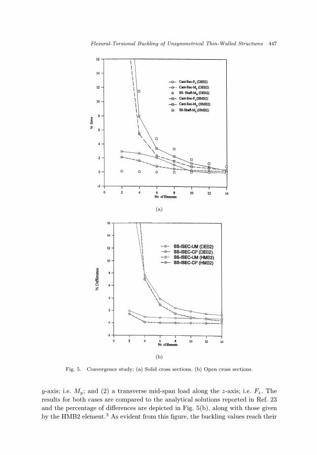
5.2.1. A convergence study
Three sets of beam lateral torsional buckling problems are utilized to assess the
convergence properties of the developed model. The first is a transversely loaded
cantilever with a rectangular cross section; designated as Cant-Rec. The geometrical
data as well as material properties are given in Table 1. Two cases of loading
conditions are considered: (1) a tip vertical load along the z-axis; i.e. Fz , and (2)
an end moment about the y-axis, i.e. My. The buckling load/moment predicted by
the DEB2 element are compared to the analytical solutions given by Timoshenko
and Gere15 and the percentage of errors are depicted in Fig. 5(a).
The analytical solutions for these two cases of loading are 0.10033 N and
7.854 N.cm, respectively. Comparisons are also presented using the results obtained
with the HMB2 element3 and these are also depicted in Fig. 5(a). As evident from
this figure, two DEB2 elements produce solutions with errors of 2.9% and 2.1%,
respectively, for the two cases of loading. Compared to the results obtained by the
HMB2 element,3 such errors are 40% and 27%, respectively, when the same number
of elements is used. Using more number of elements, the errors are reduced to reach
0.05% and 0.2%, respectively, with 12 DEB2 elements.
The second set deals with a (flexural) buckling of a torsionally loaded simply
supported circular shaft; designated as SS-Shaft in Table 1. The results for the
critical values are compared with the closed form solution obtained by Zigler22 and
depicted in Fig. 5(a), along with those produced by the HMB2 element.3 The value
of buckling moment reaches its convergence using 4 DEB2 elements with an error
of 0.35%. Such error is 11.4% when four HMB2 elements are used.
In the third set, we considered a problem of a transversely loaded simply sup-
ported beam with I-shaped cross section;23 designated as SS-Isec (see Table 1).
Two cases of loading conditions are considered here: (1) a uniform moment about
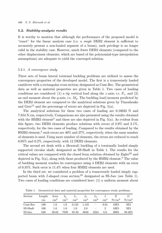
Table 1. Geometrical data and material properties for convergence study problems.
Section Length Area Iy Iz Ip Iw J E G
cm cm2 cm4 cm4 cm4 cm6 cm4 N/cm2 N/cm2
Cant-Rec 100 1.0 1.0 0.125 1.125 – 0.01 10E3 5E3
SS-Shaft 100 1.0 1.0 1.0 2.0 – 2 10E3 5E3
SS-Isec 640 30.62 7939 85.50 6048 3224 6.0 30E6 99.4E5
December 10, 2002 18:0 WSPC/165-IJSSD 00065
Flexural-Torsional Buckling of Unsymmetrical Thin-Walled Structures 447
(a)
(b)
Fig. 5. Convergence study; (a) Solid cross sections. (b) Open cross sections.
y-axis; i.e. My; and (2) a transverse mid-span load along the z-axis; i.e. Fz . The
results for both cases are compared to the analytical solutions reported in Ref. 23
and the percentage of differences are depicted in Fig. 5(b), along with those given
by the HMB2 element.3 As evident from this figure, the buckling values reach their
December 10, 2002 18:0 WSPC/165-IJSSD 00065
448 S. S. Marzouk et al.
convergence using 6 DEB2 elements where the differences are 0.05% and 0.9%, res-
pectively. On the other hand, such values of differences are 2.9% and 3.9% when
the same number of the HMB2 elements is utilized.
It is seen from the above results that the DEB2 model exhibits an excellent con-
vergence. In all cases a mesh of two to four elements yields the converged solution.
5.2.2. Comparison with shell models
This example concerns the out of plane buckling of a simply supported beam with
a T-shaped cross section. The beam is transversely loaded at is mid span. Unlike
the problem considered previously, the Wagner effect contribution to the geometric
stiffness becomes important here. The beam length is 550 mm, top and flange
thickness is 1.0 mm, flange width is 38 mm, and web height is 65 mm. The beam
is made of material with Young’s modulus E = 70960 MPa, and Poisson’s ratio
ν = 0.321. The beam is analyzed using 6 DEB2 elements and its lateral torsional
buckling is compared with those obtained using two complicated shell models24,25
in Table 2. Note that the difference is less than 0.2%
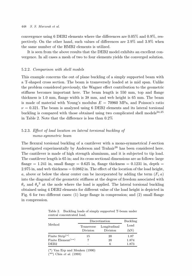
5.2.3. Effect of load location on lateral torsional buckling of
mono-symmetric beam
The flexural torsional buckling of a cantilever with a mono-symmetrical I-section
investigated experimentally by Anderson and Trahair26 has been considered here.
The cantilever is made of high strength aluminum, and it is subjected to tip load.
The cantilever length is 65 in; and its cross sectional dimensions are as follows: large
flange = 1.241 in, small flange = 0.625 in, flange thickness = 0.1231 in, depth =
2.975 in, and web thickness = 0.0862 in. The effect of the location of the load height,
a, above or below the shear center can be incorporated by adding the term (Fz a)
into the diagonal of the geometric stiffness at the degree of freedom associated with
θx and θy2 at the node where the load is applied. The lateral torsional buckling
obtained using 4 DEB2 elements for different value of the load height is depicted in
Fig. 6 for two different cases: (1) large flange in compression; and (2) small flange
in compression.
Table 2. Buckling loads of simply supported T-beam undercentral concentrated load.
Discretization BucklingMethod
Transverse Longitudinal Load
Division Division (kN)
Finite Strip(∗) 15 20 1.87
Finite Element(∗∗) 7 20 1.874DEB2 – 6 1.873
(*) Van Erp and Menken (1990)(**) Chin et al. (1993)
December 10, 2002 18:0 WSPC/165-IJSSD 00065
Flexural-Torsional Buckling of Unsymmetrical Thin-Walled Structures 449
Fig. 6. Buckling of mono-symmetrical cantilevers.
The experimental results obtained by Anderson and Trahair26 along with the
analytical solution reported by Chan and Kitipornchai4 are also presented in this
figure. It can be seen that the results produced by the DEB2 element are in very
good agreement with both experimental and analytical buckling loads. It is worth
to notice that the bucking load increases when the larger flange is in compression.
The closer the applied load to the compression flange, the higher value of the lateral
torsional buckling is predicted.
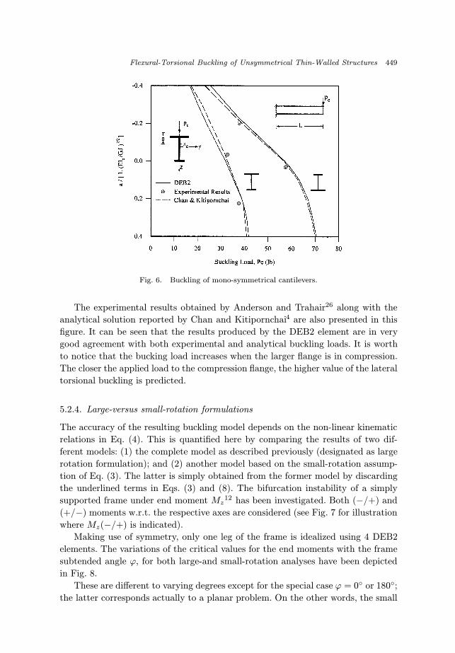
5.2.4. Large-versus small-rotation formulations
The accuracy of the resulting buckling model depends on the non-linear kinematic
relations in Eq. (4). This is quantified here by comparing the results of two dif-
ferent models: (1) the complete model as described previously (designated as large
rotation formulation); and (2) another model based on the small-rotation assump-
tion of Eq. (3). The latter is simply obtained from the former model by discarding
the underlined terms in Eqs. (3) and (8). The bifurcation instability of a simply
supported frame under end moment Mz12 has been investigated. Both (−/+) and
(+/−) moments w.r.t. the respective axes are considered (see Fig. 7 for illustration
where Mz(−/+) is indicated).
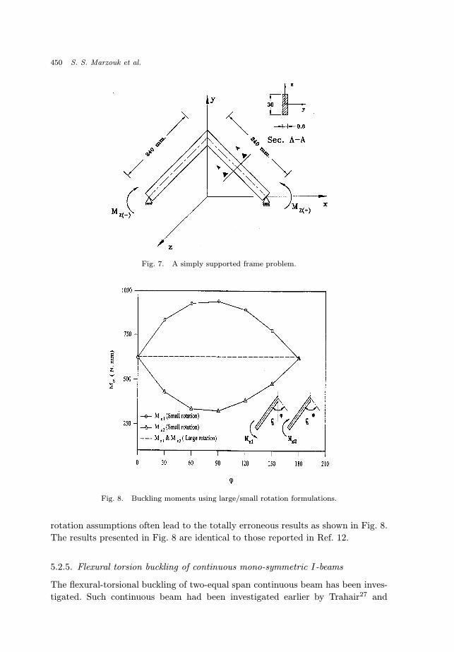
Making use of symmetry, only one leg of the frame is idealized using 4 DEB2
elements. The variations of the critical values for the end moments with the frame
subtended angle ϕ, for both large-and small-rotation analyses have been depicted
in Fig. 8.
These are different to varying degrees except for the special case ϕ = 0◦ or 180◦;
the latter corresponds actually to a planar problem. On the other words, the small
December 10, 2002 18:0 WSPC/165-IJSSD 00065
450 S. S. Marzouk et al.
Fig. 7. A simply supported frame problem.
Fig. 8. Buckling moments using large/small rotation formulations.
rotation assumptions often lead to the totally erroneous results as shown in Fig. 8.
The results presented in Fig. 8 are identical to those reported in Ref. 12.
5.2.5. Flexural torsion buckling of continuous mono-symmetric I-beams
The flexural-torsional buckling of two-equal span continuous beam has been inves-
tigated. Such continuous beam had been investigated earlier by Trahair27 and
December 10, 2002 18:0 WSPC/165-IJSSD 00065
Flexural-Torsional Buckling of Unsymmetrical Thin-Walled Structures 451
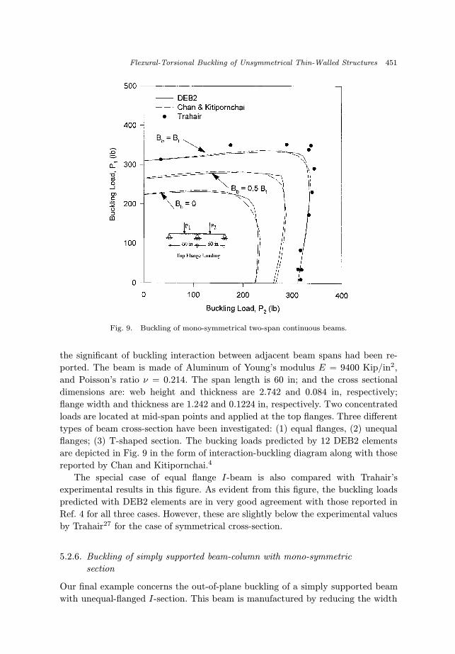
Fig. 9. Buckling of mono-symmetrical two-span continuous beams.
the significant of buckling interaction between adjacent beam spans had been re-
ported. The beam is made of Aluminum of Young’s modulus E = 9400 Kip/in2,
and Poisson’s ratio ν = 0.214. The span length is 60 in; and the cross sectional
dimensions are: web height and thickness are 2.742 and 0.084 in, respectively;
flange width and thickness are 1.242 and 0.1224 in, respectively. Two concentrated
loads are located at mid-span points and applied at the top flanges. Three different
types of beam cross-section have been investigated: (1) equal flanges, (2) unequal
flanges; (3) T-shaped section. The bucking loads predicted by 12 DEB2 elements
are depicted in Fig. 9 in the form of interaction-buckling diagram along with those
reported by Chan and Kitipornchai.4
The special case of equal flange I-beam is also compared with Trahair’s
experimental results in this figure. As evident from this figure, the buckling loads
predicted with DEB2 elements are in very good agreement with those reported in
Ref. 4 for all three cases. However, these are slightly below the experimental values
by Trahair27 for the case of symmetrical cross-section.
5.2.6. Buckling of simply supported beam-column with mono-symmetric
section
Our final example concerns the out-of-plane buckling of a simply supported beam
with unequal-flanged I-section. This beam is manufactured by reducing the width
December 10, 2002 18:0 WSPC/165-IJSSD 00065
452 S. S. Marzouk et al.
of one flange of a doubly symmetric section having the following geometrical data:
flange width = 20 cm, web height = 31.3 cm, and flange/web thickness = 1.0 cm.
The Young’s modulus and Poisson’s ratio are 210×103 MPa and 0.26, respectively.
For purpose of discussion we defined the following parameters
µ =AFC
AFC +AFT; ρ =
IzCIzC + IzT
; rz =
√Iz
A
where AFC and AFT are the area of compression and tension flanges, respectively;
IzC and IzT are the moment of inertia of compression and tension flanges, respec-
tively, about the z-axis; and rz is the slenderness ratio.
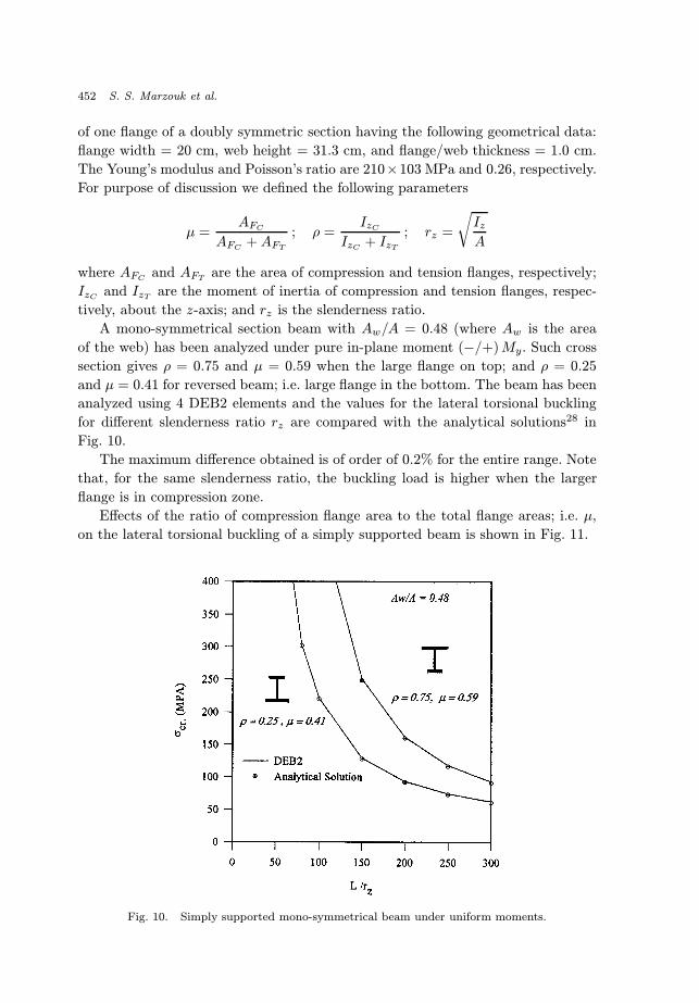
A mono-symmetrical section beam with Aw/A = 0.48 (where Aw is the area
of the web) has been analyzed under pure in-plane moment (−/+)My. Such cross
section gives ρ = 0.75 and µ = 0.59 when the large flange on top; and ρ = 0.25
and µ = 0.41 for reversed beam; i.e. large flange in the bottom. The beam has been
analyzed using 4 DEB2 elements and the values for the lateral torsional buckling
for different slenderness ratio rz are compared with the analytical solutions28 in
Fig. 10.
The maximum difference obtained is of order of 0.2% for the entire range. Note
that, for the same slenderness ratio, the buckling load is higher when the larger
flange is in compression zone.
Effects of the ratio of compression flange area to the total flange areas; i.e. µ,
on the lateral torsional buckling of a simply supported beam is shown in Fig. 11.
Fig. 10. Simply supported mono-symmetrical beam under uniform moments.
December 10, 2002 18:0 WSPC/165-IJSSD 00065
Flexural-Torsional Buckling of Unsymmetrical Thin-Walled Structures 453
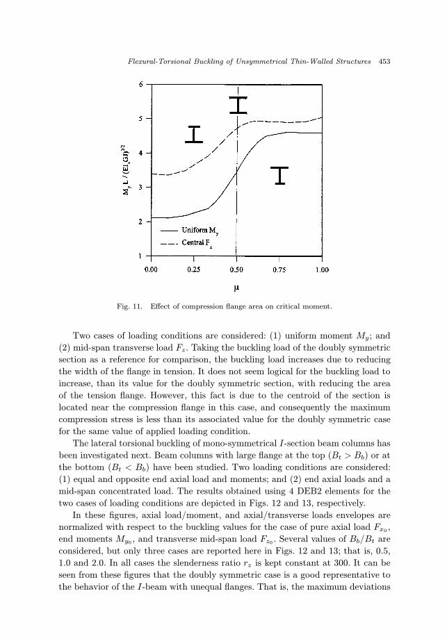
Fig. 11. Effect of compression flange area on critical moment.
Two cases of loading conditions are considered: (1) uniform moment My; and
(2) mid-span transverse load Fz. Taking the buckling load of the doubly symmetric
section as a reference for comparison, the buckling load increases due to reducing
the width of the flange in tension. It does not seem logical for the buckling load to
increase, than its value for the doubly symmetric section, with reducing the area
of the tension flange. However, this fact is due to the centroid of the section is
located near the compression flange in this case, and consequently the maximum
compression stress is less than its associated value for the doubly symmetric case
for the same value of applied loading condition.
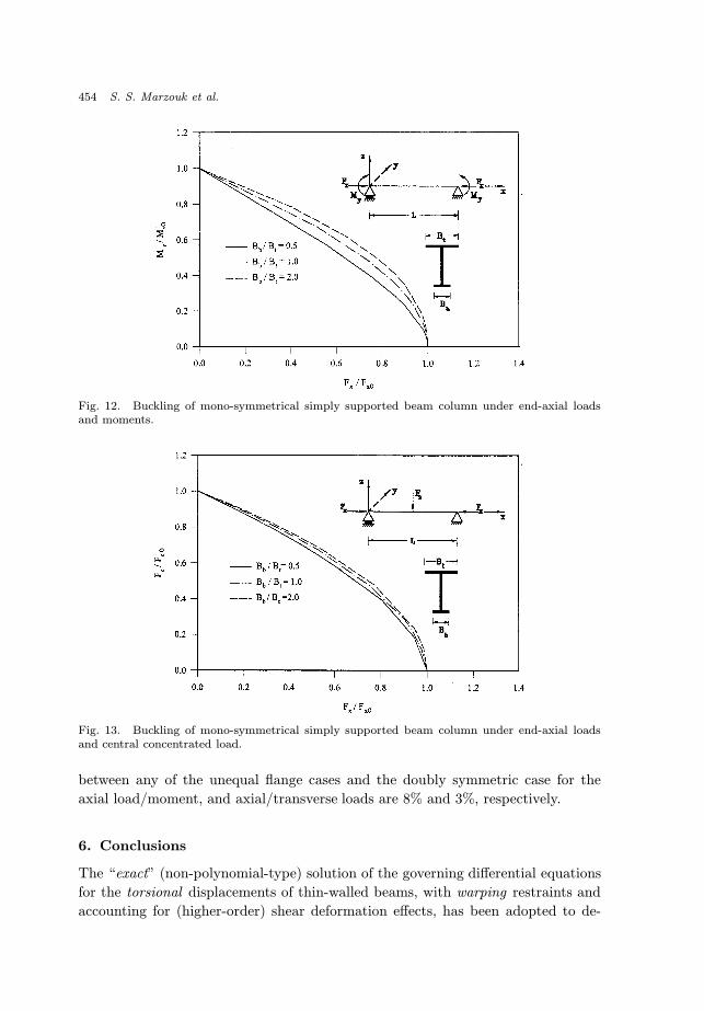
The lateral torsional buckling of mono-symmetrical I-section beam columns has
been investigated next. Beam columns with large flange at the top (Bt > Bb) or at
the bottom (Bt < Bb) have been studied. Two loading conditions are considered:
(1) equal and opposite end axial load and moments; and (2) end axial loads and a
mid-span concentrated load. The results obtained using 4 DEB2 elements for the
two cases of loading conditions are depicted in Figs. 12 and 13, respectively.
In these figures, axial load/moment, and axial/transverse loads envelopes are
normalized with respect to the buckling values for the case of pure axial load Fx0 ,
end moments My0 , and transverse mid-span load Fz0 . Several values of Bb/Bt are
considered, but only three cases are reported here in Figs. 12 and 13; that is, 0.5,
1.0 and 2.0. In all cases the slenderness ratio rz is kept constant at 300. It can be
seen from these figures that the doubly symmetric case is a good representative to
the behavior of the I-beam with unequal flanges. That is, the maximum deviations
December 10, 2002 18:0 WSPC/165-IJSSD 00065
454 S. S. Marzouk et al.
Fig. 12. Buckling of mono-symmetrical simply supported beam column under end-axial loadsand moments.
Fig. 13. Buckling of mono-symmetrical simply supported beam column under end-axial loadsand central concentrated load.
between any of the unequal flange cases and the doubly symmetric case for the
axial load/moment, and axial/transverse loads are 8% and 3%, respectively.
6. Conclusions
The “exact” (non-polynomial-type) solution of the governing differential equations
for the torsional displacements of thin-walled beams, with warping restraints and
accounting for (higher-order) shear deformation effects, has been adopted to de-
December 10, 2002 18:0 WSPC/165-IJSSD 00065
Flexural-Torsional Buckling of Unsymmetrical Thin-Walled Structures 455
velop the shape functions in a two-noded beam element for spatial analysis of
linear and nonlinear (buckling) problems. The overall formulation is capable of pre-
dicting all significant modes of deformations; i.e. stretching, bending, shear, torsion
and warping. It is also valid for different types of sections (i.e. open, closed, or
mixed), and this is accomplished by utilizing the kinematical description account-
ing for combined flexural and torsional-warping effects, Wagner-effect contributions
for the unsymmetric cross-sections, etc. Even in coarse meshes, the solutions ob-
tained with the developed model were shown to be “very” rapidly convergent, sta-
ble, and computationally efficient. A large number of numerical examples have also
demonstrated the versatility of such model in practical applications. In particular,
the new element has consistently demonstrated its superiority compared to the
other state-of-art finite element modeling techniques (i.e. using the more common
polynomial/Lagrangian-type interpolations).
References
1. M. H. El-Zanaty and D. W. Murray, “Non-linear finite element analysis of steel frame,”J. Struct. Eng. ASCE 109(2), pp. 353–368, 1983.
2. A. S. Gendy and A. F. Saleeb, “Generalized mixed finite element model for pre-andpost-quasistatic buckling response of thin-walled framed structures,” Int. J. Num.Meth. Eng. 37, pp. 292–322, 1994.
3. A. F. Saleeb, T. Y. P. Chang and A. S. Gendy, “Effective modeling of spatial bucklingof beam assemblages, accounting for warping constraints and rotation dependency ofmoment,” Int. J. Num. Meth. Eng. 33, pp. 469–502, 1992.
4. S. L. Chan and S. Kitipornchai, “Geometric non-linear analysis of asymmetric thin-walled beam-columns,” Eng. Struct. 9, pp. 243–254, 1987.
5. A. Conic and M. Gattass, “Natural approach for geometric non-linear analysis ofthin-walled frames,” Int. J. Num. Meth. Eng. 30, pp. 207–231, 1990.
6. H. Chen and G. E. Blandford, “Thin-walled space frames. I: Large deformation anal-ysis theory,” J. Struct. Eng. ASCE 117(8), pp. 2499–2520, 1991.
7. B. A. Izzuddin, “An Eurlian approach to the large displacement analysis of thin-walledframes,” Proc. Inst. Civ. Eng. Struct. Build., London England 110(1), pp. 50–65,1995.
8. B. A. Izzuddin and S. D. Lloyd, “Large displacement analysis of elastoplastic thin-walled frames. I: Formulation and implementation,” J. Struct. Eng. ASCE 122(8),pp. 905–914, 1996.
9. J. C. Simo and L. Vu-Quoc, “A three-dimensional finite strain rod model. Part II:Computational aspects,” Comp. Meth. Appl. Mech. Eng. 53, pp. 79–116, 1986.
10. K. J. Bathe, Finite Element Procedures in Engineering Analysis, Prentice-Hall,Englewood Cliffs, NJ., 1996.
11. A. S. Gendy, A. F. Saleeb and T. Y. P. Chang, “Generalized thin walled beam modelsfor flexural torsional analysis,” Comput. Struct. 44, pp. 531–550, 1992.
12. J. H. Argyris, O. Hilbert, G. A. Malejannakis and D. W. Scharpf, “On the geometricalstiffness of a beam in space — A consistent V.W. approach,” Comp. Meth. Appl. Mech.Eng. 30, pp. 105–131, 1979.
13. J. H. Argyris, “An excursion into large rotations,” Comp. Meth. Appl. Mech. Eng.32, pp. 85–155, 1982.
December 10, 2002 18:0 WSPC/165-IJSSD 00065
456 S. S. Marzouk et al.
14. J. C. Simo and L. Vu-Quoc, “A geometrically-exact beam model incorporation shearand torsion warping deformation,” Int. J. Solids Struct. 27(3), pp. 371–393, 1991.
15. S. P. Timoshenko and J. M. Gere, Theory of Elastic Stability, McGraw-Hill, NewYork, 1961.
16. V. Z. Vlasov, Thin-Walled Elastic Beams, 2nd edn., Israel Program for ScientificTranslation, Jerusalem, Israel, 1961.
17. A. Gjelsvik, The Theory of Thin-Walled Bars, Wiley, New York, 1981.18. S. J. Medwadowski, “Warping moment distribution,” J. Struct. Eng. 111, pp. 453–
461, 1985.19. A. V. Rutenbery and W. K. Tso, “Torsional analysis of perforated core structure,” J.
Struct. Div. ASCE 101, pp. 539–550, 1975.20. A. V. Rutenberg and M. Eisenberger, “Torsional analysis method for perforated
cores,” J. Struct. Eng. 112, pp. 1207–1227, 1986.21. I. A. Macleed and H. M. Hosny, “France analysis of shear wall cores,” J. Struct. Div.
ASCE 103, pp. 2037–2047, 1977.22. H. Zielger, Principles of Structural Stability, Blaisdell, MA, 1968.23. A. Prokic, “New warping function for thin-walled beams. II: finite element method
and application,” J. Struct. Eng. 122, pp. 1443–1451, 1996.24. G. M. Van-Erp and C. M. Menken, “The spline finite strip method in the buckling
analyses of thin-walled structures,” Commun. Appl. Num. Meth. 6, pp. 477–484, 1990.25. C.-K. Chin, G. A. Faris, F. G. A. Al-Brmani and S. Kitipornchai, “Finite element
method for buckling analysis of plate structures,” 119, pp. 1048–1068, 1993.26. J. M. Anderson and N. S. Trahair, “Stability of mono-symmetric beams and canti-
levers,” J. Struct. Div. ASCE 98, pp. 269–286, 1972.27. N. S. Trahair, “Elastic stability of continuous beams,” J. Struct. Div. ASCE 95, (ST6)
pp. 1295–1312, 1969.28. S. Kitipornchai and N. S. Trahair, “Buckling properties of mono-symmetric I-beams,”
J. Struct. Div., ASCE 106, pp. 941–957, 1980.

Copyright of International Journal of Structural Stability & Dynamics is the property of World Scientific
Publishing Company and its content may not be copied or emailed to multiple sites or posted to a listserv
without the copyright holder's express written permission. However, users may print, download, or email
articles for individual use.
Related Documents


