Modeling volume deformation in gravity-type cages with distributed bottom weights or a rigid tube-sinker Chai-Cheng Huang a, * , Hung-Jie Tang a , Jin-Yuan Liu b a Department of Marine Environment and Engineering, National Sun Yat-sen University, Kaohsiung 804, Taiwan b Institute of Undersea Technology, Asian Pacific Ocean Research Center, National Sun Yat-sen University, Kaohsiung 804, Taiwan Received 26 May 2006; accepted 6 April 2007 Abstract Fish mortality caused by the shrinkage and deformation of gravity-type cage net volume during typhoons is of great concern to the marine cage aquaculture industry. To remedy this deformation problem, we developed a specially designed tube-sinker to replace the weights that are commonly used at the bottom of cage nets. Herein, we describe the features of our new cage net system, the formation of motion equations, a new approach to estimating the volume reduction coefficient, and physical model tests in a hydrodynamic wave tank. Results of the numerical simulation and the experimental measurements show good agreement. This study indicates that the tube-sinker not only improves the volume reduction coefficient by 10% for most wave conditions, but also that it significantly reduces severe fluctuations in volume deformation, thereby reducing fish fatalities due to skin abrasion with the net. # 2007 Elsevier B.V. All rights reserved. Keywords: Cage aquaculture; Volume reduction coefficient; Tube-sinker 1. Introduction Fisheries represent a centuries-old method of human exploitation of marine resources. Fishery resources are usually abundant, but over fishing in near shore waters, reclamation and exploitation along the coastal zone, and dumping of pollution into the sea have diminished fish nursery grounds at a rapid rate. In Taiwan, this decline in near shore fishery resources has pushed the fisheries industry to consider marine cage aquaculture, in which fish can be raised in deeper water. However, because Taiwan is located in a subtropical zone, every year typhoons severely damage the cages and the resulting net volume shrinkage and severe deformation cause high fish mortality. A more flexible cage system might alleviate this problem, but an engineering analysis is needed to evaluate the dynamic performance and reliability of such a system. Kawakami (1964) proposed a relatively reliable semi-empirical formula for a flexible net subjected to the impact of currents. It is based on the drag force concept, which includes the effects of the material used, mesh size, current velocity, and the density of water. Milne (1972) and Woods Hole Engineering Associates (1984) proposed a series of detailed drag coefficients for different materials under fouled/unfouled conditions. Aarsens et al. (1990) and Loland (1991) further decomposed the external forces into two components, drag and lift, which take into account the angle between current velocity and the normal direction of the net panel. They also proposed the shielding effect in calculating the total force on a net cage system with a series of cage units. Lader et al. (2003) conducted a www.elsevier.com/locate/aqua-online Aquacultural Engineering 37 (2007) 144–157 * Corresponding author. Tel.: +886 7 525 5169; fax: +886 7 525 5060. E-mail address: [email protected] (C.-C. Huang). 0144-8609/$ – see front matter # 2007 Elsevier B.V. All rights reserved. doi:10.1016/j.aquaeng.2007.04.003

Welcome message from author
This document is posted to help you gain knowledge. Please leave a comment to let me know what you think about it! Share it to your friends and learn new things together.
Transcript
www.elsevier.com/locate/aqua-online
Aquacultural Engineering 37 (2007) 144–157
Modeling volume deformation in gravity-type cages with
distributed bottom weights or a rigid tube-sinker
Chai-Cheng Huang a,*, Hung-Jie Tang a, Jin-Yuan Liu b
a Department of Marine Environment and Engineering, National Sun Yat-sen University, Kaohsiung 804, Taiwanb Institute of Undersea Technology, Asian Pacific Ocean Research Center, National Sun Yat-sen University, Kaohsiung 804, Taiwan
Received 26 May 2006; accepted 6 April 2007
Abstract
Fish mortality caused by the shrinkage and deformation of gravity-type cage net volume during typhoons is of great concern to
the marine cage aquaculture industry. To remedy this deformation problem, we developed a specially designed tube-sinker to
replace the weights that are commonly used at the bottom of cage nets. Herein, we describe the features of our new cage net system,
the formation of motion equations, a new approach to estimating the volume reduction coefficient, and physical model tests in a
hydrodynamic wave tank. Results of the numerical simulation and the experimental measurements show good agreement. This
study indicates that the tube-sinker not only improves the volume reduction coefficient by 10% for most wave conditions, but also
that it significantly reduces severe fluctuations in volume deformation, thereby reducing fish fatalities due to skin abrasion with the
net.
# 2007 Elsevier B.V. All rights reserved.
Keywords: Cage aquaculture; Volume reduction coefficient; Tube-sinker
1. Introduction
Fisheries represent a centuries-old method of human
exploitation of marine resources. Fishery resources are
usually abundant, but over fishing in near shore waters,
reclamation and exploitation along the coastal zone, and
dumping of pollution into the sea have diminished fish
nursery grounds at a rapid rate. In Taiwan, this decline
in near shore fishery resources has pushed the fisheries
industry to consider marine cage aquaculture, in which
fish can be raised in deeper water. However, because
Taiwan is located in a subtropical zone, every year
typhoons severely damage the cages and the resulting
net volume shrinkage and severe deformation cause
* Corresponding author. Tel.: +886 7 525 5169;
fax: +886 7 525 5060.
E-mail address: [email protected] (C.-C. Huang).
0144-8609/$ – see front matter # 2007 Elsevier B.V. All rights reserved.
doi:10.1016/j.aquaeng.2007.04.003
high fish mortality. A more flexible cage system might
alleviate this problem, but an engineering analysis is
needed to evaluate the dynamic performance and
reliability of such a system.
Kawakami (1964) proposed a relatively reliable
semi-empirical formula for a flexible net subjected to
the impact of currents. It is based on the drag force
concept, which includes the effects of the material used,
mesh size, current velocity, and the density of water.
Milne (1972) and Woods Hole Engineering Associates
(1984) proposed a series of detailed drag coefficients for
different materials under fouled/unfouled conditions.
Aarsens et al. (1990) and Loland (1991) further
decomposed the external forces into two components,
drag and lift, which take into account the angle between
current velocity and the normal direction of the net
panel. They also proposed the shielding effect in
calculating the total force on a net cage system with a
series of cage units. Lader et al. (2003) conducted a
C.-C. Huang et al. / Aquacultural Engineering 37 (2007) 144–157 145
series of experiments to investigate forces acting on and
deformation to a net cage in a uniform current. They
concluded that the total forces on a flexible net cage and
its deformation depend on each other. Lader and
Enerhaug (2005) developed a super element approach
that can be used to predict the global forces on a flexible
net sheet. Tsukrov et al. (2003) employed a ‘‘finite
element method with consistent net element concepts’’
to model the hydrodynamic response of net panels to
environmental loading and applied it to evaluate the
performance of a tension leg fish cage. Fredriksson et al.
(2003) adopted both a finite element method and a
stochastic approach to analyze the motion response
characteristics of an in situ fish cage and the mooring
line tension response to wave forces. Their results
provided valuable information about the dynamical
processes of the fish cage under environmental forces.
Suhey et al. (2005) worked on numerical modeling of
the cage structure using a finite element method; they
showed that an inflated structure has sufficient stiffness
to be used as the structural support within a fish cage.
DeCew et al. (2005) performed an extensive set of
experiments in a wave tank using regular and random
waves to investigate the dynamic response of a modified
gravity cage system. Tsukrov et al. (2005) applied a
finite element numerical model to feed buoy mooring
systems containing nonlinear elastic components such
as feeding hoses. Their numerical simulation provided
predictions about the overall dynamics of the system
and the maximum values of tension in critical
components. Murali et al. (2005) adopted the physical
model to analyze the effect of a cage combined with a
floating breakwater, which has potential applications in
protecting minor ports and harbors, such as fisheries and
recreational harbors, where stringent tranquility
requirements are not warranted.
To date, the global demand for fishery production is
still increasing, and this demand will push fish cage-
based fisheries further towards the open sea. Use of such
non-sheltered offshore marine sites will require improve-
ments in the design, performance, and reliability of
aquaculture cage systems. This paper, following Huang
et al. (2006a), focuses on the dynamic analysis of net
cages based on the ‘‘lumped mass method and net plane
element’’ concepts. The advantage of this concept is that
the whole net cage system can be decomposed into
flexible net plane elements, line elements, bottom
weights, and rigid bodies (such as a floating collar) that
can be divided into several straight tube elements. All
elements are subjected to environmental forces that
evenly distribute to the corresponding nodes. These
nodes, or lumped mass centers, form a system of
uncoupled motion equations that can be solved by the
Runge-Kutta method. Huang et al. (2006b) applied this
numerical model to a full-scale fish cage with a single-
point mooring system deployed in the open sea of
Taiwan; the cable tension was investigated and shown to
agree well with predictions.
Huge commodity losses due to the shrinkage and
deformation of net volume and to fish fatalities from
abrasion by the cage net have been reported frequently
by local fish farmers after typhoons. The objectives of
this work were to analyze the feasibility of using a tube-
sinker to alleviate volume deformation of gravity-type
net cage systems and to predict the maximum tension
force at anchor, which is important in the design of
mooring systems. This paper is structured as follows:
Section 2 discusses features of offshore cage structures,
including the fish rearing system and the mooring
system. Section 3 describes the motion equations, and
Section 4 offers a new approach to estimating the cage
net volume reduction coefficient. Section 5 describes a
physical model study and compares the results with
numerical predictions. Section 6 is an application to a
real open sea cage case. Finally, Section 7 presents our
conclusions and suggestions.
2. Features of offshore cage structures
Most aquaculture gravity-type cages consist of
floating collars, nets, weights, buoys, mooring lines,
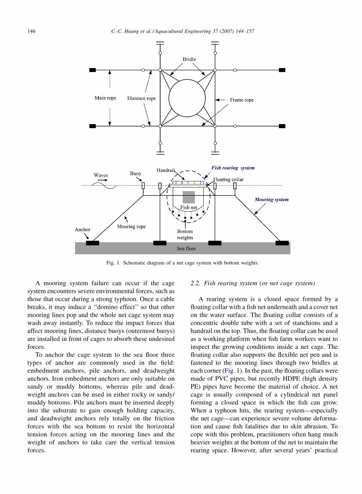
and anchors. Fig. 1 shows a common type of offshore
cage structure, except that most aquaculture cage
systems have a series of cages in a row instead of a
single cage. Generally speaking, an aquaculture cage
system can be decomposed into two parts, a mooring
system and a fish rearing system; the latter includes a
floating collar and a fish net.
2.1. Mooring system
The main purpose of the mooring system is to fasten
net cages at a specific location and to prevent cages from
drifting away as environmental loadings act on them.
Therefore, the strength and durability of the material
used for mooring lines are important factors. The
material most commonly used by the local fishing
industry is Nylon, PET (Polyester), and PP (Poly-
propylene). The specific gravity of Nylon is 1.14 and
PET is 1.38; both are heavier than the water’s specific
gravity, and when installed in the field these materials
tend to sink to the sea floor. The specific gravity of PP is
about 0.91, and it may float on the water surface if
disconnected from the bottom anchors.
C.-C. Huang et al. / Aquacultural Engineering 37 (2007) 144–157146
Fig. 1. Schematic diagram of a net cage system with bottom weights.
A mooring system failure can occur if the cage
system encounters severe environmental forces, such as
those that occur during a strong typhoon. Once a cable
breaks, it may induce a ‘‘domino effect’’ so that other
mooring lines pop and the whole net cage system may
wash away instantly. To reduce the impact forces that
affect mooring lines, distance buoys (outermost buoys)
are installed in front of cages to absorb these undesired
forces.
To anchor the cage system to the sea floor three
types of anchor are commonly used in the field:
embedment anchors, pile anchors, and deadweight
anchors. Iron embedment anchors are only suitable on
sandy or muddy bottoms, whereas pile and dead-
weight anchors can be used in either rocky or sandy/
muddy bottoms. Pile anchors must be inserted deeply
into the substrate to gain enough holding capacity,
and deadweight anchors rely totally on the friction
forces with the sea bottom to resist the horizontal
tension forces acting on the mooring lines and the
weight of anchors to take care the vertical tension
forces.
2.2. Fish rearing system (or net cage system)
A rearing system is a closed space formed by a
floating collar with a fish net underneath and a cover net
on the water surface. The floating collar consists of a
concentric double tube with a set of stanchions and a
handrail on the top. Thus, the floating collar can be used
as a working platform when fish farm workers want to
inspect the growing conditions inside a net cage. The
floating collar also supports the flexible net pen and is
fastened to the mooring lines through two bridles at
each corner (Fig. 1). In the past, the floating collars were
made of PVC pipes, but recently HDPE (high density
PE) pipes have become the material of choice. A net
cage is usually composed of a cylindrical net panel
forming a closed space in which the fish can grow.
When a typhoon hits, the rearing system—especially
the net cage—can experience severe volume deforma-
tion and cause fish fatalities due to skin abrasion. To
cope with this problem, practitioners often hang much
heavier weights at the bottom of the net to maintain the
rearing space. However, after several years’ practical
C.-C. Huang et al. / Aquacultural Engineering 37 (2007) 144–157 147
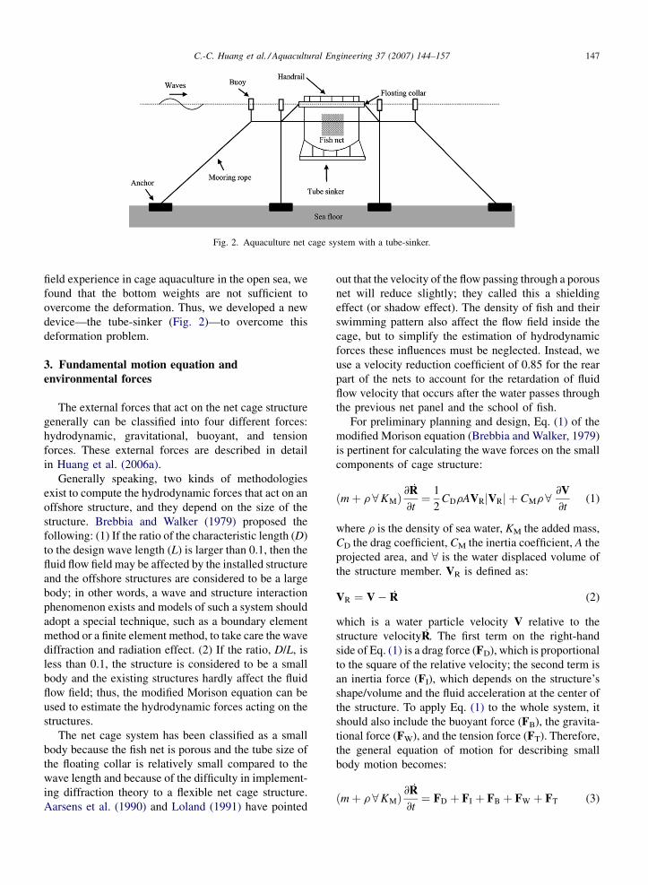
Fig. 2. Aquaculture net cage system with a tube-sinker.
field experience in cage aquaculture in the open sea, we
found that the bottom weights are not sufficient to
overcome the deformation. Thus, we developed a new
device—the tube-sinker (Fig. 2)—to overcome this
deformation problem.
3. Fundamental motion equation and
environmental forces
The external forces that act on the net cage structure
generally can be classified into four different forces:
hydrodynamic, gravitational, buoyant, and tension
forces. These external forces are described in detail
in Huang et al. (2006a).
Generally speaking, two kinds of methodologies
exist to compute the hydrodynamic forces that act on an
offshore structure, and they depend on the size of the
structure. Brebbia and Walker (1979) proposed the
following: (1) If the ratio of the characteristic length (D)
to the design wave length (L) is larger than 0.1, then the
fluid flow field may be affected by the installed structure
and the offshore structures are considered to be a large
body; in other words, a wave and structure interaction
phenomenon exists and models of such a system should
adopt a special technique, such as a boundary element
method or a finite element method, to take care the wave
diffraction and radiation effect. (2) If the ratio, D/L, is
less than 0.1, the structure is considered to be a small
body and the existing structures hardly affect the fluid
flow field; thus, the modified Morison equation can be
used to estimate the hydrodynamic forces acting on the
structures.
The net cage system has been classified as a small
body because the fish net is porous and the tube size of
the floating collar is relatively small compared to the
wave length and because of the difficulty in implement-
ing diffraction theory to a flexible net cage structure.
Aarsens et al. (1990) and Loland (1991) have pointed
out that the velocity of the flow passing through a porous
net will reduce slightly; they called this a shielding
effect (or shadow effect). The density of fish and their
swimming pattern also affect the flow field inside the
cage, but to simplify the estimation of hydrodynamic
forces these influences must be neglected. Instead, we
use a velocity reduction coefficient of 0.85 for the rear
part of the nets to account for the retardation of fluid
flow velocity that occurs after the water passes through
the previous net panel and the school of fish.
For preliminary planning and design, Eq. (1) of the
modified Morison equation (Brebbia and Walker, 1979)
is pertinent for calculating the wave forces on the small
components of cage structure:
ðmþ r 8KMÞ@R
@t¼ 1
2CDrAVRjVRj þ CMr8 @V
@t(1)
where r is the density of sea water, KM the added mass,
CD the drag coefficient, CM the inertia coefficient, A the
projected area, and 8 is the water displaced volume of
the structure member. VR is defined as:
VR ¼ V� R (2)
which is a water particle velocity V relative to the
structure velocityR. The first term on the right-hand
side of Eq. (1) is a drag force (FD), which is proportional
to the square of the relative velocity; the second term is
an inertia force (FI), which depends on the structure’s
shape/volume and the fluid acceleration at the center of
the structure. To apply Eq. (1) to the whole system, it
should also include the buoyant force (FB), the gravita-
tional force (FW), and the tension force (FT). Therefore,
the general equation of motion for describing small
body motion becomes:
ðmþ r 8KMÞ@R
@t¼ FD þ FI þ FB þ FW þ FT (3)
C.-C. Huang et al. / Aquacultural Engineering 37 (2007) 144–157148
where the drag force and the inertia force are associated
with motion of the fluids and are regarded as the
hydrodynamic forces.
When analyzing the hydrodynamic forces on a fish
rearing system, it is common to consider the flexible net
and the rigid floating collar separately. Huang et al.
(2006a) described in detail the external force calcula-
tions for the net cage system, so here we focus on the
calculations for the mooring system.
3.1. Forces on mooring lines
The purpose of mooring lines is to keep the cage
structure from drifting away while the waves and
currents exert environmental loadings on the structure.
Most mooring lines are submerged at least 3–5 m below
the water surface (Fig. 1). To avoid entanglement with
boat propellers, bridle lines start from the connection
point beneath the innermost buoys and tilt up slightly
towards the floating collar that sits on the water surface.
Because mooring lines are actually submerged, the
external forces acting on them should include hydro-
dynamic, gravitational, buoyant, and tension forces.
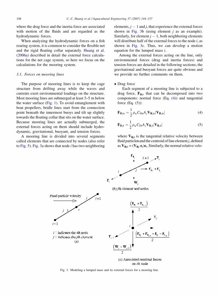
A mooring line is divided into several segments
called elements that are connected by nodes (also refer
to Fig. 5). Fig. 3a shows that node i has two neighboring
Fig. 3. Modeling a lumped mass and its
elements, j � 1 and j, that experience the external forces
shown in Fig. 3b (using element j as an example).
Similarly, for element j � 1, both neighboring elements
will distribute half of the external forces to the node i, as
shown in Fig. 3c. Thus, we can develop a motion
equation for the lumped mass i.
Among the external forces acting on the line, only
environmental forces (drag and inertia forces) and
tension forces are detailed in the following sections; the
gravitational and buoyant forces are quite obvious and
we provide no further comments on them.
� D
ex
rag force
Each segment of a mooring line is subjected to a
drag force, FDj, that can be decomposed into two
components: normal force (Eq. (4)) and tangential
force (Eq. (5)):
FD jn ¼1
2rwCDnA jVR jnjVR jnj (4)
FD jt ¼1
2rwCDtA jVR jtjVR jtj (5)
where VRjt is the tangential relative velocity between
fluid particles and the centroid of line element j, defined
as VRjt = (VRj�et)et. Similarly, the normal relative velo-
ternal forces for a mooring line.
C.-C. Huang et al. / Aquacultural Engineering 37 (2007) 144–157 149
F
city, VRjn, is defined as VRjn = VRj � VRjt. The pro-
jected area, Aj, is defined as the diameter of the mooring
line times the segment length (Aj = Dj‘j). Based on
Webster (1976), CDn and CDt can be determined by
Eqs. (6) and (7):
CDn ¼
0:0 Ren � 0:1
0:45þ 5:93
ðRenÞ0:330:1<Ren � 400
1:27 400<Ren � 105
0:3 Ren� 105
8>>>>><>>>>>:
(6)
CDt ¼1:88
ðRetÞ0:740:1<Ret � 100:55
0:062 Ret > 100:55
8<: (7)
where Ren = (jVRjnj�Dj)/n; Ret = (jVRjtj�Dj)/n; and n is
the kinematic viscosity of sea water.
� I
nertia forceThe inertia force of the jth segment of a mooring
line can be computed by the Morison equation and
expressed as:
FI j ¼ rw 8 jCM
@V j
@t(8)
The mid-point, or the centroid, of the segment is
used to compute the fluid particle acceleration term on
the right hand side.
� T
ension forceA mooring line segment is considered to be an
elastic material with a slender body. When subjected
to external forces, it may elongate or shrink in length.
In the case of elongation, the segment will create a
restoring force, whereas for shrinkage no restoring
force occurs. The restoring force is often regarded as a
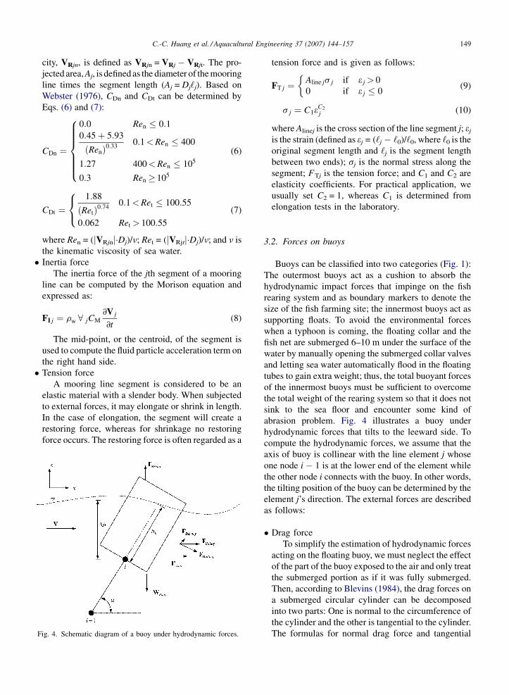
ig. 4. Schematic diagram of a buoy under hydrodynamic forces.
tension force and is given as follows:
FT j ¼Aline js j if e j > 0
0 if e j � 0
�(9)
s j ¼ C1eC2
j (10)
where Alinej is the cross section of the line segment j; ej
is the strain (defined as ej = (‘j � ‘0)/‘0, where ‘0 is the
original segment length and ‘j is the segment length
between two ends); sj is the normal stress along the
segment; FTj is the tension force; and C1 and C2 are
elasticity coefficients. For practical application, we
usually set C2 = 1, whereas C1 is determined from
elongation tests in the laboratory.
3.2. Forces on buoys
Buoys can be classified into two categories (Fig. 1):
The outermost buoys act as a cushion to absorb the
hydrodynamic impact forces that impinge on the fish
rearing system and as boundary markers to denote the
size of the fish farming site; the innermost buoys act as
supporting floats. To avoid the environmental forces
when a typhoon is coming, the floating collar and the
fish net are submerged 6–10 m under the surface of the
water by manually opening the submerged collar valves
and letting sea water automatically flood in the floating
tubes to gain extra weight; thus, the total buoyant forces
of the innermost buoys must be sufficient to overcome
the total weight of the rearing system so that it does not
sink to the sea floor and encounter some kind of
abrasion problem. Fig. 4 illustrates a buoy under
hydrodynamic forces that tilts to the leeward side. To
compute the hydrodynamic forces, we assume that the
axis of buoy is collinear with the line element j whose
one node i � 1 is at the lower end of the element while
the other node i connects with the buoy. In other words,
the tilting position of the buoy can be determined by the
element j’s direction. The external forces are described
as follows:
� D
rag forceTo simplify the estimation of hydrodynamic forces
acting on the floating buoy, we must neglect the effect
of the part of the buoy exposed to the air and only treat
the submerged portion as if it was fully submerged.
Then, according to Blevins (1984), the drag forces on
a submerged circular cylinder can be decomposed
into two parts: One is normal to the circumference of
the cylinder and the other is tangential to the cylinder.
The formulas for normal drag force and tangential
C.-C. Huang et al. / Aquacultural Engineering 37 (2007) 144–157150
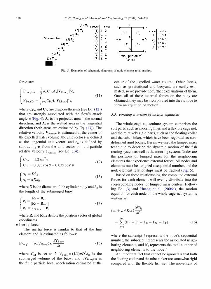
Fig. 5. Examples of schematic diagrams of node-element relationships.
force are:
FBuoyDn ¼1
2rwCDnAnjVRBuoyj2en
FBuoyDt ¼1
2rwCDtAtjVRBuoyj2et
8><>: (11)
where CDn and CDt are drag coefficients (see Eq. (12))
that are strongly associated with the flow’s attack
angle, u (Fig. 4); An is the projected area in the normal
direction; and At is the wetted area in the tangential
direction (both areas are estimated by Eq. (13)). The
relative velocity VRBuoy is estimated at the center of
the expelled water volume; the unit vector et is defined
as the tangential unit vector; and en is defined by
subtracting et from the unit vector of fluid particle
relative velocity eVRBuoy(see Eq. (14)).
CDn ¼ 1:2 sin2 u
CDt ¼ 0:083 cos u � 0:035 cos2 u
((12)
An ¼ DhB
At ¼ pDhB
�(13)
where D is the diameter of the cylinder buoy and hB is
the length of the submerged buoy.
et ¼Ri � Ri�1
jRi � Ri�1jen ¼ eVRBuoy
� et
8<: (14)
where Ri and Ri�1 denote the position vector of global
coordinates.
� I
nertia forceThe inertia force is similar to that of the line
element and is estimated as follows:
FBuoyI ¼ rw 8 BuoyCM
@VBuoy
@t(15)
where CM is set to 2; 8Buoy = (1/4)pD2hB is the
submerged volume of the buoy; and @VBuoy/@t is
the fluid particle local acceleration estimated at the
center of the expelled water volume. Other forces,
such as gravitational and buoyant, are easily esti-
mated, so we provide no further explanations of them.
Once all of these external forces on the buoy are
obtained, they may be incorporated into the i’s node to
form an equation of motion.
3.3. Forming a system of motion equations
The whole cage aquaculture system comprises the
soft parts, such as mooring lines and a flexible cage net,
and the relatively rigid parts, such as the floating collar
and the tube-sinker, which have been regarded as non-
deformed rigid bodies. Herein we used the lumped mass
technique to describe the dynamic motion of the fish
rearing system as well as the mooring system. Nodes are
the positions of lumped mass for the neighboring
elements that experience external forces. All nodes and
elements must be assigned a sequential number, and the
node-element relationships must be tracked (Fig. 5).
Based on these relationships, the computed external
forces for each element will evenly distribute into the
corresponding nodes, or lumped mass centers. Follow-
ing Eq. (3) and Huang et al. (2006a), the motion
equation for each node on the whole cage-net system is
written as:
ðmi þ r 8KMiÞ@2Ri
@t2
¼XNe
j¼1
ðFD þ FI þ FB þ FW þ FTÞ j (16)
where the subscript i represents the node’s sequential
number, the subscript j represents the associated neigh-
boring elements, and Ne represents the total number of
neighboring elements to the node i.
An important fact that cannot be ignored is that both
the floating collar and the tube-sinker are somewhat rigid
compared with the flexible fish net. The movement of
C.-C. Huang et al. / Aquacultural Engineering 37 (2007) 144–157 151
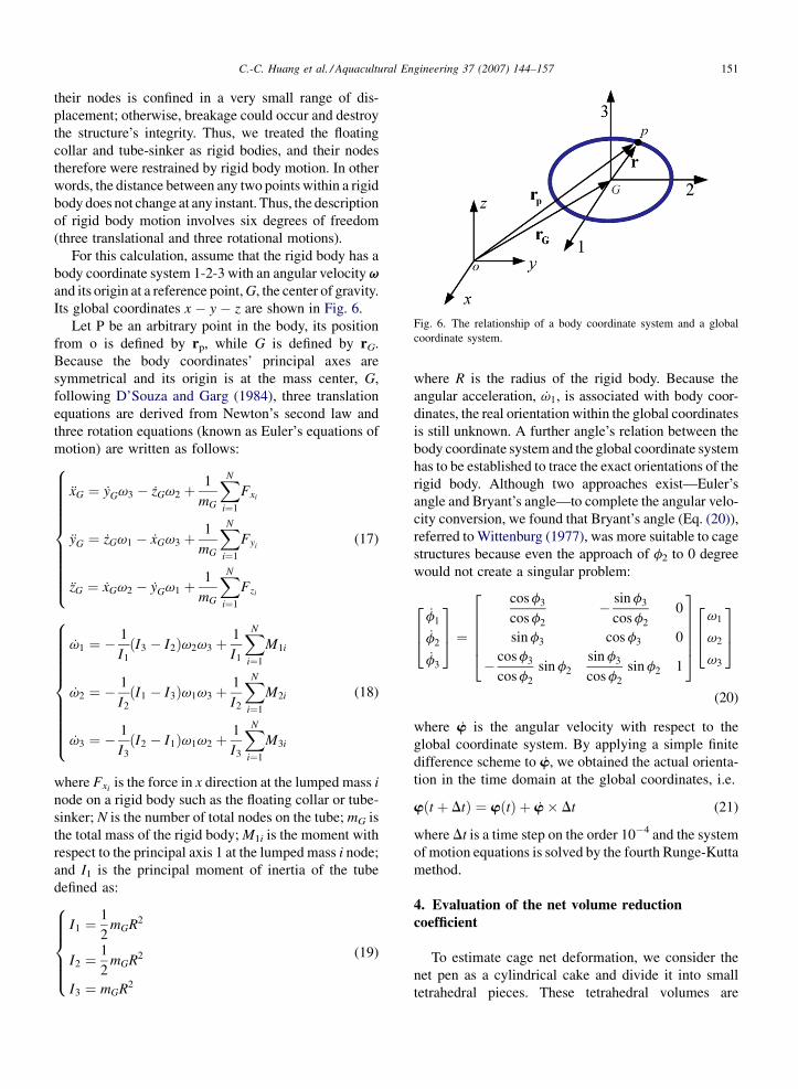
Fig. 6. The relationship of a body coordinate system and a global
coordinate system.
their nodes is confined in a very small range of dis-
placement; otherwise, breakage could occur and destroy
the structure’s integrity. Thus, we treated the floating
collar and tube-sinker as rigid bodies, and their nodes
therefore were restrained by rigid body motion. In other
words, the distance between any two points within a rigid
body does not change at any instant. Thus, the description
of rigid body motion involves six degrees of freedom
(three translational and three rotational motions).
For this calculation, assume that the rigid body has a
body coordinate system 1-2-3 with an angular velocity vand its origin at a reference point, G, the center of gravity.
Its global coordinates x � y � z are shown in Fig. 6.
Let P be an arbitrary point in the body, its position
from o is defined by rp, while G is defined by rG.
Because the body coordinates’ principal axes are
symmetrical and its origin is at the mass center, G,
following D’Souza and Garg (1984), three translation
equations are derived from Newton’s second law and
three rotation equations (known as Euler’s equations of
motion) are written as follows:
xG ¼ yGv3 � zGv2 þ1
mG
XN
i¼1
Fxi
yG ¼ zGv1 � xGv3 þ1
mG
XN
i¼1
Fyi
zG ¼ xGv2 � yGv1 þ1
mG
XN
i¼1
Fzi
8>>>>>>>>>><>>>>>>>>>>:
(17)
v1 ¼ �1
I1
ðI3 � I2Þv2v3 þ1
I1
XN
i¼1
M1i
v2 ¼ �1
I2
ðI1 � I3Þv1v3 þ1
I2
XN
i¼1
M2i
v3 ¼ �1
I3
ðI2 � I1Þv1v2 þ1
I3
XN
i¼1
M3i
8>>>>>>>>>><>>>>>>>>>>:
(18)
where Fxi is the force in x direction at the lumped mass i
node on a rigid body such as the floating collar or tube-
sinker; N is the number of total nodes on the tube; mG is
the total mass of the rigid body; M1i is the moment with
respect to the principal axis 1 at the lumped mass i node;
and I1 is the principal moment of inertia of the tube
defined as:
I1 ¼1
2mGR2
I2 ¼1
2mGR2
I3 ¼ mGR2
8>>>><>>>>:
(19)
where R is the radius of the rigid body. Because the
angular acceleration, v1, is associated with body coor-
dinates, the real orientation within the global coordinates
is still unknown. A further angle’s relation between the
body coordinate system and the global coordinate system
has to be established to trace the exact orientations of the
rigid body. Although two approaches exist—Euler’s
angle and Bryant’s angle—to complete the angular velo-
city conversion, we found that Bryant’s angle (Eq. (20)),
referred to Wittenburg (1977), was more suitable to cage
structures because even the approach of f2 to 0 degree
would not create a singular problem:
f1
f2
f3
264
375 ¼
cos f3
cos f2
� sin f3
cos f2
0
sin f3 cos f3 0
� cos f3
cos f2
sin f2
sin f3
cos f2
sin f2 1
266664
377775
v1
v2
v3
264
375
(20)
where w is the angular velocity with respect to the
global coordinate system. By applying a simple finite
difference scheme to w, we obtained the actual orienta-
tion in the time domain at the global coordinates, i.e.
wðt þ DtÞ ¼ wðtÞ þ w� Dt (21)
where Dt is a time step on the order 10�4 and the system
of motion equations is solved by the fourth Runge-Kutta
method.
4. Evaluation of the net volume reduction
coefficient
To estimate cage net deformation, we consider the
net pen as a cylindrical cake and divide it into small
tetrahedral pieces. These tetrahedral volumes are
C.-C. Huang et al. / Aquacultural Engineering 37 (2007) 144–157152
Table 1
Specifications of the physical model
Parameter Size Material properties
Floating collar Plastic
Circumference (cm) 162 Density = 0.95 g/cm3
Tube diameter (cm) 2
Total mass (g) 596
Buoy Styrofoam
Diameter (cm) 4.7
Length (cm) 2.5
Total mass (g) 5.87
Mooring line Nylon twist
Diameter (cm) 0.265 Density = 1.14 g/cm3
Unit mass (g/cm) 0.03879
Breaking strength (N) 1538
Elastic coefficient C1 (N/cm2) 75342
Fish net Nylon
Twine diameter (cm) 0.02 Density = 1.14 g/cm3
Total mass (g) 34.776 Solidity = 0.17
Mesh size (cm) 0.46
Net depth (cm) 30
Breaking strength (N) 32.7
Elastic coefficient C1 (N/cm2) 242475
Tube-sinker Plastic
Circumference (cm) 162 Density = 0.95 g/cm3
Tube diameter (cm) 1.178
Total mass (g) 226
Bottom weights Tin
Unit mass (g/piece) 28.25 Density = 2.71 g/cm3
Number of pieces 8
Total mass (g) 226
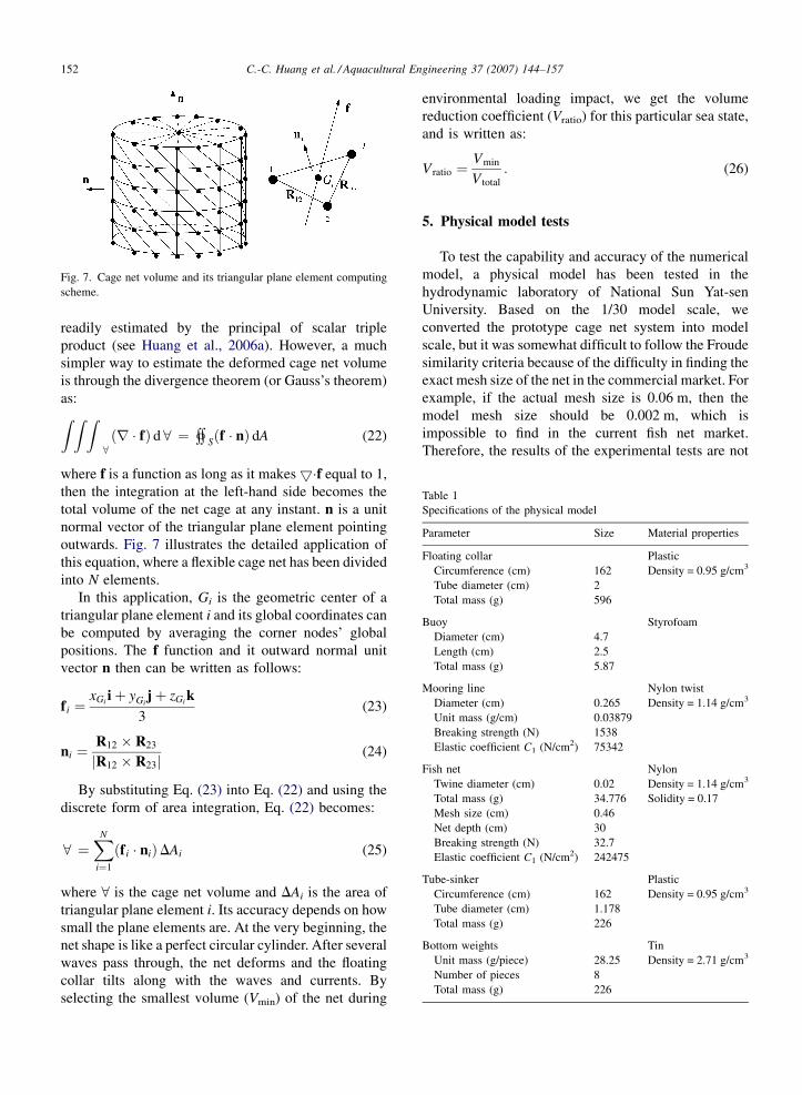
Fig. 7. Cage net volume and its triangular plane element computing
scheme.
readily estimated by the principal of scalar triple
product (see Huang et al., 2006a). However, a much
simpler way to estimate the deformed cage net volume
is through the divergence theorem (or Gauss’s theorem)
as:Z Z Z8ðr � fÞ d 8 ¼ « Sðf � nÞ dA (22)
where f is a function as long as it makes5�f equal to 1,
then the integration at the left-hand side becomes the
total volume of the net cage at any instant. n is a unit
normal vector of the triangular plane element pointing
outwards. Fig. 7 illustrates the detailed application of
this equation, where a flexible cage net has been divided
into N elements.
In this application, Gi is the geometric center of a
triangular plane element i and its global coordinates can
be computed by averaging the corner nodes’ global
positions. The f function and it outward normal unit
vector n then can be written as follows:
f i ¼xGi iþ yGi
jþ zGi k
3(23)
ni ¼R12 � R23
jR12 � R23j(24)
By substituting Eq. (23) into Eq. (22) and using the
discrete form of area integration, Eq. (22) becomes:
8 ¼XN
i¼1
ðf i � niÞDAi (25)
where 8 is the cage net volume and DAi is the area of
triangular plane element i. Its accuracy depends on how
small the plane elements are. At the very beginning, the
net shape is like a perfect circular cylinder. After several
waves pass through, the net deforms and the floating
collar tilts along with the waves and currents. By
selecting the smallest volume (Vmin) of the net during
environmental loading impact, we get the volume
reduction coefficient (Vratio) for this particular sea state,
and is written as:
V ratio ¼Vmin
V total
: (26)
5. Physical model tests
To test the capability and accuracy of the numerical
model, a physical model has been tested in the
hydrodynamic laboratory of National Sun Yat-sen
University. Based on the 1/30 model scale, we
converted the prototype cage net system into model
scale, but it was somewhat difficult to follow the Froude
similarity criteria because of the difficulty in finding the
exact mesh size of the net in the commercial market. For
example, if the actual mesh size is 0.06 m, then the
model mesh size should be 0.002 m, which is
impossible to find in the current fish net market.
Therefore, the results of the experimental tests are not
C.-C. Huang et al. / Aquacultural Engineering 37 (2007) 144–157 153
Table 2
Experimental test cases for a net cage system with bottom weights
Cases 1 2 3 4 5 6
Depth (cm) 85 85 85 85 85 85
Current (cm/s) 14.86 14.86 14.86 14.86 14.86 14.86
Period (s) 1.58 1.77 1.97 1.77 1.77 1.77
Wave height H (cm) 9.66 9.55 11.09 12.31 13.99 15.34
Dimensionless kH 0.1717 0.1434 0.1436 0.1848 0.2101 0.2303
Steepness (H/L) 0.0249 0.0210 0.0212 0.0271 0.0308 0.0337
Table 3
Experimental test cases for a net cage system with a tube-sinker
Cases 1 2 3 4 5 6
Depth (cm) 85 85 85 85 85 85
Current (cm/s) 14.86 14.86 14.86 14.86 14.86 14.86
Period (s) 1.57 1.77 1.96 1.77 1.78 1.77
Wave height H (cm) 9.64 9.39 11.48 12.28 13.83 15.48
Dimensionless kH 0.1730 0.1410 0.1497 0.1844 0.2060 0.2324
Steepness (H/L) 0.0251 0.0207 0.0221 0.0270 0.0301 0.0341
completely applicable to the real world, and the
experimental results only serve as a check for the
numerical model. Table 1 presents the specifications of
the physical model.
We conducted the experiments in a two-dimensional
wave tank (35 m long, 1 m wide, 1.2 m high). The tank
generates waves and a uniform current at the same time.
We tested six types of waves in this study, keeping the
current (14.86 cm/s) and water depth (85 cm) constant.
Each experiment’s wave steepness (H/L) was as large as
possible to simulate the high sea situations and yet not
to over the limitation of linear wave theory. The
objectives of this experimental study is to see how good
is the performance of a net cage with a tube-sinker
system comparing to a bottom weight system during
waves and currents attack. Tables 2 and 3 provide the
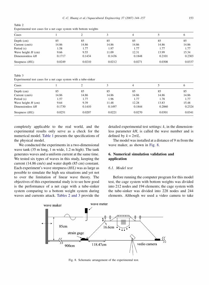
Fig. 8. Schematic arrangement
detailed experimental test settings: k, in the dimension-
less parameter kH, is called the wave number and is
defined by k = 2p/L.
The model was installed at a distance of 9 m from the
wave maker, as shown in Fig. 8.
6. Numerical simulation validation and
application
6.1. Model test
Before running the computer program for this model
test, the cage system with bottom weights was divided
into 212 nodes and 194 elements; the cage system with
the tube-sinker was divided into 228 nodes and 244
elements. Although we used a video camera to take
of the experimental test.
C.-C. Huang et al. / Aquacultural Engineering 37 (2007) 144–157154
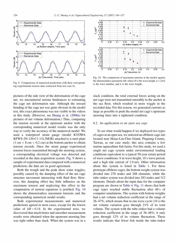
Fig. 9. Comparisons of numerical predictions with their correspond-
ing experimental tension data (extracted from test case 6).
Fig. 10. The comparison of maximum tensions at the anchor against
the dimensionless parameter kH, where H is the wave height, k = 2p/L
is the wave number, and L is the wave length.
pictures of the side view of the deformation of the cage
net, we encountered serious hindrances to estimating
the cage net deformation rate. Although the inward
bending of the cage net was quite obvious in the model
test, this exact phenomena was not visible in the videos
in this study. (However, see Huang et al. (2006a) for
pictures of net volume deformation.) Thus, comparing
the tension records at the upstream anchor with the
corresponding numerical model results was the only
way to verify the accuracy of the numerical model. We
used a waterproof strain gauge (model KYOWA
KFWS-2N-120-C1-11L3M2R) attached to a steel plate
(1 cm � 8 cm � 0.2 cm) at the bottom anchor to obtain
tension records. Once the strain gauge experienced
tension forces transmitted through the mooring system,
a corresponding electrical voltage was detected and
recorded in the data acquisition system. Fig. 9 shows a
sample of experimental data compared with a numerical
prediction; the data are in good agreement.
Both the trough and the peak show some wiggles,
possibly caused by the damping effect of the net cage
structure movement interacting with fluid flow. How-
ever, this damping effect has little influence on the
maximum tension and neglecting this effect in the
computation of motion equations is justified. Fig. 10
shows the dimensionless maximum tensions and the
corresponding numerical model results.
Both experimental measurements and numerical
predictions agreed in most cases, except for the lowest
value of kH = 0.14. In the experimental tests, we
discovered that much better and smoother measurement
results were obtained when the upstream mooring line
was tight rather than slack. When the system was in a
slack condition, the total external forces acting on the
net cage were not transmitted smoothly to the anchor at
the sea floor, which resulted in more wiggle in the
recorded data. For this reason, we generated currents as
large as possible to push the model net cage’s upstream
mooring lines into a tightened condition.
6.2. An application to an open sea cage
To see what would happen if we deployed two types
of cages at an open sea, we selected an offshore cage site
located near Hsiao-Liu-Chiu Island, Pingtung County,
Taiwan, as our case study; this area contains a few
marine aquaculture fish farms. For this study, we used a
single net cage system under environmental loading
conditions equivalent to a typical 50-year return period
of wave conditions: 6 m wave height, 10 s wave period,
and a high tide current of 1.0 m/s. Other information
about this system is listed in Table 1. For these
prototype offshore cages, the bottom weight system was
divided into 270 nodes and 288 elements, while the
tube-sinker system was divided into 283 nodes and 312
elements. Details about the input data for the computer
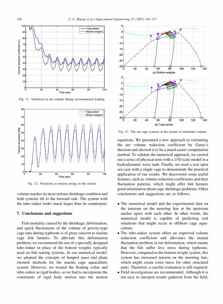
program are shown in Table 4. Fig. 11 shows that both
cage types reached stable fluctuation after 60 s of
computer simulations. The system with bottom weights
had a net volume reduction coefficient in the range of
26–47%, which means that in one wave cycle (10 s) the
net volume variation goes through 21% of its total
volume. The system with the tube-sinker had a volume
reduction coefficient in the range of 36–48%; it only
goes through 12% of its volume fluctuation. These
results indicate that fewer fish inside the tube-sinker
C.-C. Huang et al. / Aquacultural Engineering 37 (2007) 144–157 155
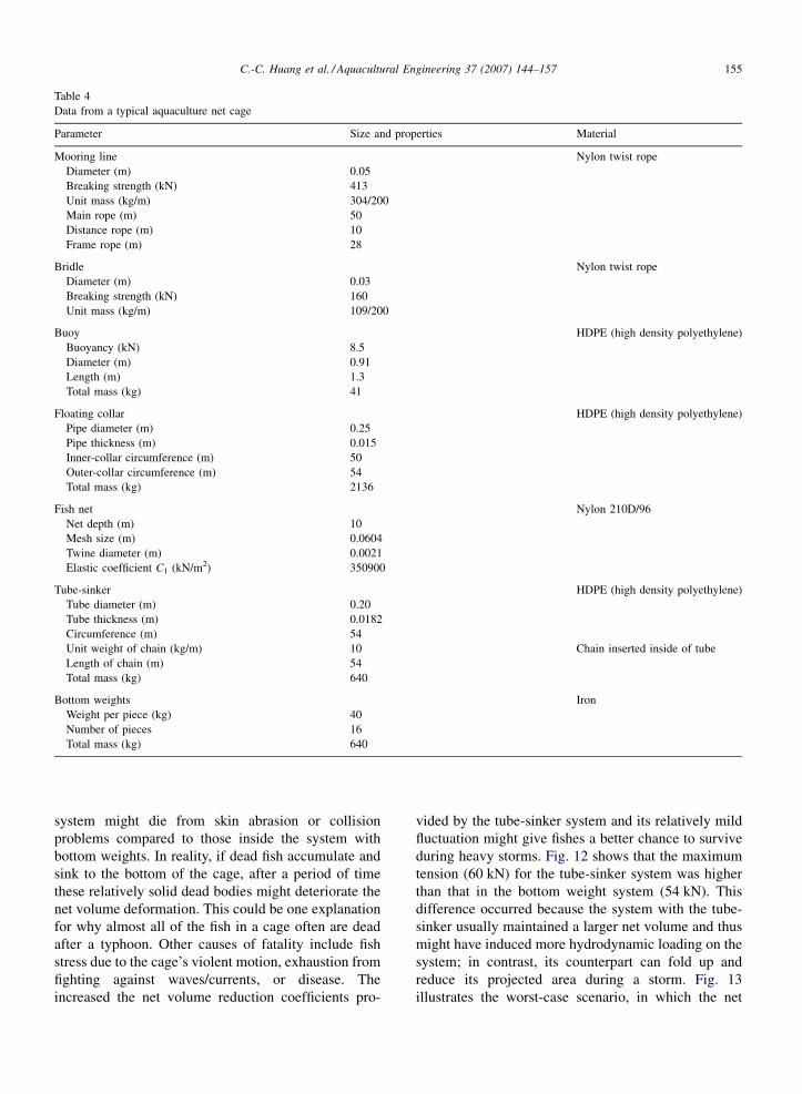
Table 4
Data from a typical aquaculture net cage
Parameter Size and properties Material
Mooring line Nylon twist rope
Diameter (m) 0.05
Breaking strength (kN) 413
Unit mass (kg/m) 304/200
Main rope (m) 50
Distance rope (m) 10
Frame rope (m) 28
Bridle Nylon twist rope
Diameter (m) 0.03
Breaking strength (kN) 160
Unit mass (kg/m) 109/200
Buoy HDPE (high density polyethylene)
Buoyancy (kN) 8.5
Diameter (m) 0.91
Length (m) 1.3
Total mass (kg) 41
Floating collar HDPE (high density polyethylene)
Pipe diameter (m) 0.25
Pipe thickness (m) 0.015
Inner-collar circumference (m) 50
Outer-collar circumference (m) 54
Total mass (kg) 2136
Fish net Nylon 210D/96
Net depth (m) 10
Mesh size (m) 0.0604
Twine diameter (m) 0.0021
Elastic coefficient C1 (kN/m2) 350900
Tube-sinker HDPE (high density polyethylene)
Tube diameter (m) 0.20
Tube thickness (m) 0.0182
Circumference (m) 54
Unit weight of chain (kg/m) 10 Chain inserted inside of tube
Length of chain (m) 54
Total mass (kg) 640
Bottom weights Iron
Weight per piece (kg) 40
Number of pieces 16
Total mass (kg) 640
system might die from skin abrasion or collision
problems compared to those inside the system with
bottom weights. In reality, if dead fish accumulate and
sink to the bottom of the cage, after a period of time
these relatively solid dead bodies might deteriorate the
net volume deformation. This could be one explanation
for why almost all of the fish in a cage often are dead
after a typhoon. Other causes of fatality include fish
stress due to the cage’s violent motion, exhaustion from
fighting against waves/currents, or disease. The
increased the net volume reduction coefficients pro-
vided by the tube-sinker system and its relatively mild
fluctuation might give fishes a better chance to survive
during heavy storms. Fig. 12 shows that the maximum
tension (60 kN) for the tube-sinker system was higher
than that in the bottom weight system (54 kN). This
difference occurred because the system with the tube-
sinker usually maintained a larger net volume and thus
might have induced more hydrodynamic loading on the
system; in contrast, its counterpart can fold up and
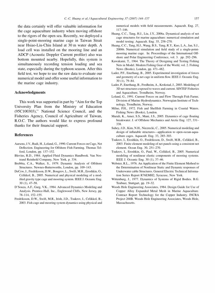
reduce its projected area during a storm. Fig. 13
illustrates the worst-case scenario, in which the net
C.-C. Huang et al. / Aquacultural Engineering 37 (2007) 144–157156
Fig. 11. Variations in net volume during environmental loading.
Fig. 12. Variations in tension acting on the anchor.
Fig. 13. The net cage systems at the instant of minimum volume.
volume reaches its most serious shrinkage condition and
both systems tilt to the leeward side. The system with
the tube-sinker looks much larger than its counterpart.
7. Conclusions and suggestions
Fish mortality caused by the shrinkage, deformation,
and quick fluctuations of the volume of gravity-type
cage nets during typhoons is of great concern to marine
cage fish farmers. To alleviate this deformation
problem, we recommend the use of a specially designed
tube-sinker in place of the bottom weights typically
used on fish rearing systems. In our numerical model,
we adopted the concepts of lumped mass and plane
element methods for the marine cage aquaculture
system. However, we treated the floating collar and
tube-sinker as rigid bodies, so we had to incorporate the
constraints of rigid body motion into the motion
equations. We presented a new approach to estimating
the net volume reduction coefficient by Gauss’s
theorem and showed it to be a much easier computation
method. To validate the numerical approach, we carried
out a series of physical tests with a 1/30 scale model in a
hydrodynamic wave tank. Finally, we used a real open
sea case with a single cage to demonstrate the practical
application of our results. We discovered some useful
features, such as volume reduction coefficients and their
fluctuation patterns, which might offer fish farmers
good information about cage shrinkage problems. Other
conclusions and suggestions are as follows:
� T
he numerical model and the experimental data onthe tensions on the mooring line at the upstream
anchor agree with each other. In other words, the
numerical model is capable of predicting real
situations that might occur in offshore cage aqua-
culture.
� T
he tube-sinker system offers an improved volumereduction coefficient and alleviates the instant
fluctuation problem in net deformation, which means
that the fish suffer less stress during typhoons.
However, compared to the bottom weight system, this
system has increased tension on the mooring line,
which might create extra stress for other structural
parts. Therefore, a careful evaluation is still required.
� F
ield investigations are recommended. Although it isnot easy to interpret results gathered from the field,
C.-C. Huang et al. / Aquacultural Engineering 37 (2007) 144–157 157
the data certainly will offer valuable information for
the cage aquaculture industry when moving offshore
to the rigors of the open sea. Recently, we deployed a
single-point-mooring marine cage in Taiwan Strait
near Hsiao-Liu-Chiu Island at 30 m water depth. A
load cell was installed on the mooring line and an
ADCP (Acoustic Doppler Current profiler) also was
bottom mounted nearby. Hopefully, this system is
simultaneously recording tension loading and sea
state, especially during the typhoon season. After this
field test, we hope to use the raw data to evaluate our
numerical model and offer some useful information to
the marine cage industry.
Acknowledgments
This work was supported in part by ‘‘Aim for the Top
University Plan from the Ministry of Education
(95C100303),’’ National Science Council, and the
Fisheries Agency, Council of Agriculture of Taiwan,
R.O.C. The authors would like to express profound
thanks for their financial support.
References
Aarsens, J.V., Rudi, H., Loland, G., 1990. Current Forces on Cage, Net
Deflection. Engineering for Offshore Fish Farming. Thomas Tel-
ford, London, pp. 137–152.
Blevins, R.D., 1984. Applied Fluid Dynamics Handbook. Van Nos-
trand Reinhold Company, New York, p. 334.
Brebbia, C.A., Walker, S., 1979. Dynamic Analysis of Offshore
Structures. Newnes-Butterworths, London, pp. 109–143.
DeCew, J., Fredriksson, D.W., Bougrov, L., Swift, M.R., Eroshkin, O.,
Celikkol, B., 2005. Numerical and physical modeling of a mod-
ified gravity type cage and mooring system. IEEE J. Oceanic Eng.
30 (1), 47–58.
D’Souza, A.F., Garg, V.K., 1984. Advanced Dynamics Modeling and
Analysis. Prentice-Hall, Inc., Englewood Cliffs, New Jersey, pp.
78–114, 152–155.
Fredriksson, D.W., Swift, M.R., Irish, J.D., Tsukrov, I., Celikkol, B.,
2003. Fish cage and mooring system dynamics using physical and
numerical models with field measurements. Aquacult. Eng. 27,
117–146.
Huang, C.C., Tang, H.J., Liu, J.Y., 2006a. Dynamical analysis of net
cage structures for marine aquaculture: numerical simulation and
model testing. Aquacult. Eng. 35, 258–270.
Huang, C.C., Tang, H.J., Wang, B.S., Yang, R.Y., Kuo, L.A., Jan, S.J.,
2006b. Numerical simulation and field study of a single-point-
mooring marine cage. In: Proceedings of the International Off-
shore and Polar Engineering Conference, vol. 3. pp. 292–296.
Kawakami, T., 1964. The Theory of Designing and Testing Fishing
Nets in Model. Modern Fishing Gear of the World, vol. 2. Fishing
News (Books), London, pp. 471–482.
Lader, P.F., Enerhaug, B., 2005. Experimental investigation of forces
and geometry of a net cage in uniform flow. IEEE J. Oceanic Eng.
30 (1), 79–84.
Lader, P., Enerhaug, B., Fredheim, A., Krokstad, J., 2003. Modeling of
3D net structures exposed to waves and current. SINTEF Fisheries
and Aquaculture, Trondheim, Norway.
Loland, G., 1991. Current Forces on and Flow Through Fish Farms.
Division of Marine Hydrodynamics. Norwegian Institute of Tech-
nology, Trondheim, Norway.
Milne, P.H., 1972. Fish and Shellfish Farming in Coastal Waters.
Fishing News (Books), London.
Murali, K., Amer, S.S., Mani, J.S., 2005. Dynamics of cage floating
breakwater. J. of Offshore Mechanics and Arctic Eng. 127, 331–
338.
Suhey, J.D., Kim, N.H., Niezrecki, C., 2005. Numerical modeling and
design of inflatable structures—application to open-ocean-aqua-
culture cages. Aquacult. Eng. 33, 285–303.
Tsukrov, I., Eroshkin, O., Fredriksson, D., Swift, M.R., Celikkol, B.,
2003. Finite element modeling of net panels using a consistent net
element. Ocean Eng. 30, 251–270.
Tsukrov, I., Eroshkin, O., Paul, W., Celikkol, B., 2005. Numerical
modeling of nonlinear elastic components of mooring systems.
IEEE J. Oceanic Eng. 30 (1), 37–46.
Webster, R.L., 1976. An Application of the Finite Element Method to
the Determination of Nonlinear Static and Dynamic responses of
Underwater cable Structures. General Electric Technical Informa-
tion Series Report R76EMH2, Syracuse, New York.
Wittenburg, J., 1977. Dynamics of Systems of Rigid Bodies. B.G.
Teubner, Stuttgart, pp. 19–32.
Woods Hole Engineering Associates, 1984. Design Guide for Use of
Copper Alloy Expanded Metal Mesh in Marine Aquaculture.
Contract Report Technology for the Copper Industry. INCRA
Project 268B. Woods Hole Engineering Associates, Woods Hole,
Massachusetts.
Related Documents