Modeling Variants of Automotive Systems using Views Hans Gr ¨ onniger, Holger Krahn, Claas Pinkernell, and Bernhard Rumpe Institute for Software Systems Engineering Technische Universit¨ at Braunschweig, Germany Abstract: This paper presents an approach of modeling variability of automotive sys- tem architectures using function nets, views and feature diagrams. A function net models an architecture hierarchically and views are used to omit parts of such a model to focus on certain functionalities. In combination with feature diagrams that describe valid variants, the concepts of feature and variant views are introduced to model archi- tectural variants. The relationship between views, variants and the underlying com- plete architectural model is discussed. Methodological aspects that come along with this approach are considered. Keywords: Automotive Systems, Logical Architecture, Feature Modeling, Variability 1 Introduction A main challenge in developing automotive systems is the high diversity of possible vari- ants of a system architecture. A modern car consists of a lot of features a customer can choose from which leads to thousands of possible configurations. Additionally, the complexity of automotive systems is increasing rapidly coupled with a growing need for reusability of existing functionality. This is not just a development issue, but it is also getting harder to maintain and evolve running systems. Especially an intuitive notation of system architectures that considers the high number of variants is missing in today’s approaches. This paper focuses on the aspect of variability in automotive system architectures. An architecture description language based on function nets is introduced to model hierarchi- cally structured and logically distributed systems. Hierarchical decomposition allows for handling the complexity of a system architecture and the concept of views is introduced to improve system understanding. In this paper, views are used to describe features of a system. In combination with feature diagrams they also give an overview of possible variations. Variant views are introduced that abstract from a complete function net to the relevant parts of a feature in a certain variant. The paper contributes to the understanding of systems with high diversity by introducing an intuitive notation to model features and their variants. In Section 2 of this paper the modeling of automotive architectures with function nets is explained as introduced in [GHK + 07, GHK + 08]. The section also focuses on the defi- nition of views. Section 3 describes what a feature is and how feature diagrams model [GKPR08] H. Grönniger, H. Krahn, C. Pinkernell, B. Rumpe Modeling Variants of Automotive Systems using Views. In: Tagungsband Modellierungs-Workshop MBEFF: Modellbasierte Entwicklung von eingebetteten Fahrzeugfunktionen. Berlin, März 2008, Informatik-Bericht 2008-01, CFG-Fakultät, TU Braunschweig, 2008. www.se-rwth.de/publications

Welcome message from author
This document is posted to help you gain knowledge. Please leave a comment to let me know what you think about it! Share it to your friends and learn new things together.
Transcript

Modeling Variants of Automotive Systems using Views
Hans Gronniger, Holger Krahn, Claas Pinkernell, and Bernhard RumpeInstitute for Software Systems Engineering
Technische Universitat Braunschweig, Germany
Abstract: This paper presents an approach of modeling variability of automotive sys-tem architectures using function nets, views and feature diagrams. A function netmodels an architecture hierarchically and views are used to omit parts of such a modelto focus on certain functionalities. In combination with feature diagrams that describevalid variants, the concepts of feature and variant views are introduced to model archi-tectural variants. The relationship between views, variants and the underlying com-plete architectural model is discussed. Methodological aspects that come along withthis approach are considered.
Keywords: Automotive Systems, Logical Architecture, Feature Modeling, Variability
1 Introduction
A main challenge in developing automotive systems is the high diversity of possible vari-ants of a system architecture. A modern car consists of a lot of features a customercan choose from which leads to thousands of possible configurations. Additionally, thecomplexity of automotive systems is increasing rapidly coupled with a growing need forreusability of existing functionality. This is not just a development issue, but it is alsogetting harder to maintain and evolve running systems. Especially an intuitive notationof system architectures that considers the high number of variants is missing in today’sapproaches.
This paper focuses on the aspect of variability in automotive system architectures. Anarchitecture description language based on function nets is introduced to model hierarchi-cally structured and logically distributed systems. Hierarchical decomposition allows forhandling the complexity of a system architecture and the concept of views is introducedto improve system understanding. In this paper, views are used to describe features ofa system. In combination with feature diagrams they also give an overview of possiblevariations. Variant views are introduced that abstract from a complete function net to therelevant parts of a feature in a certain variant. The paper contributes to the understandingof systems with high diversity by introducing an intuitive notation to model features andtheir variants.
In Section 2 of this paper the modeling of automotive architectures with function nets isexplained as introduced in [GHK+07, GHK+08]. The section also focuses on the defi-nition of views. Section 3 describes what a feature is and how feature diagrams model
[GKPR08] H. Grönniger, H. Krahn, C. Pinkernell, B. Rumpe Modeling Variants of Automotive Systems using Views. In: Tagungsband Modellierungs-Workshop MBEFF: Modellbasierte Entwicklung von eingebetteten Fahrzeugfunktionen. Berlin, März 2008, Informatik-Bericht 2008-01, CFG-Fakultät, TU Braunschweig, 2008. www.se-rwth.de/publications

system variability. The concept of feature views is introduced and variant views are de-fined. The connection between a feature diagram, feature and variant views is explainedby examples. Section 4 considers methodological aspects and in Section 5 related work ispresented.
2 Modeling Automotive Architectures using function nets and Views
Function nets are a suitable concept for describing automotive logical architectures [vdB04,vdB06]. In our approach, we propose to use a subset of SysML internal block diagramsfor function net modeling, as described in [GHK+07, GHK+08]. The next subsectionintroduces the notation of internal block diagrams. Syntactically, internal block diagramsare valid SysML internal block diagrams [OMG06], but some additional constraints ap-ply as described in [GHK+08]. Internal block diagrams that describe function nets onlyuse directed connectors and no multiplicities. The main advantages of this notation arethe intuitive systems engineering terminology and the distinction between the form of adiagram and its use. It is possible to describe both, views and the underlying completearchitecture, with the same notation. As a consequence, we achieve a low learning effortand an easy switching of viewpoints between function nets and views. The notation itselfshould be acceptable for developers from other domains than computer science, because ituses existing systems engineering terminology.
2.1 Internal Block Diagrams
Internal block diagrams (ibd) used for function net modeling contain logical functions andtheir communication relationships [OMG06]. Blocks in the diagram can be decomposedinto further blocks to structure the architecture hierarchically or can be simple functions.The interface of a block is formed by its input and output channels.
Blocks are communicating over so called connectors which are unidirectional and logicalsignals are sent from a sender to a receiver over them. Connectors can directly connecttwo blocks ignoring hierarchical composition (cross-hierarchy communication). A signalhas exactly one sender, but it may have several receivers.
Figure 1 shows an internal block diagram of a car comfort functionality. The block consistsof a central locking system (CLS), the central locking system control unit (CLSControl-Unit), doors and a trunk. The CLSControlUnit consists of two different push-buttons anda status interpreter.
The CLS receives two external signals: AutoLockState and Speed. The system outputsCLSState to an external environment. A door can be decomposed as seen in Figure 2. Itconsists of a DoorContact and a LockControl. As you can see in Figure 1, the functionDoor is instantiated four times. In our approach the instantiation of blocks is supportedwhich increases reusability of functions and avoids redundant function definitions. Moreinformation on the instantiation mechanism can be found in [GHK+07].

Figure 1: Car comfort function
Figure 2: Decomposition of a door
Note that the example is neither complete nor does it illustrate a real design of a comfortfunction in detail.
2.2 Views
Internal block diagrams are also used to define views of a given architecture. A view isdenoted by the stereotype�view� and helps developers to focus on particular functionalityby hiding the complexity of a complete logical architecture. A view has to be consistentto an underlying internal block diagram. That means that a view consists of elements of acomplete architectural model.
Views do not introduce new elements but abstract from the whole system by omittingblocks and connectors. An exception is the possibility to model the environment of ablock and its non-digital communication. Environmental blocks (depicted by stereotype�env�), like actuators or even “the street” can be modeled. There are several possibilitiesof non-digital communication, e.g., �M� for mechanical, �E� for analogous electricalor �H� for hydraulic stimulation. First elements for an appropriate theory for at least theanalogous and digital communication is given in [SRS99]. Modeling the environment isused for better comprehensibility. It is also possible to import so called external blocks.These blocks are marked with the stereotype �ext� in order to model a view’s context inthe whole system.
Figure 3 shows a view of the running example. The view depicts a coupe variant of a carcomfort function. A coupe has only two doors and a trunk compared to the full model inFigure 1. So the rear doors are omitted.
Figure 3: View of car comfort function
Views are abstractions of a complete function net. The following consistency conditionscan be checked to validate this relationship [GHK+07]:
1. Each block in the view without a stereotype �env� must be part of the completefunction net.
2. Whole-part-relationships in the view must be present in the complete function net.However, it is permitted to leave out intermediate layers.

3. Elements that are related via a (possibly transitive) whole-part-relationship in thecomplete function net must also have this relation in a view if both elements areshown.
4. Communication relationships not marked with a stereotype shown in the view mustbe present in the logical architecture. If the concrete signal is omitted in the view,an arbitrary signal communication must exist in the complete function net.
5. Communication relationships need not be drawn to the exact source or target. Anysuperblock is sufficient if the exact source or target block is omitted.
Views on views are also supported by the notation. In that case, an additional contextcondition applies:
6. A view on a function net is a specialization of another view if both are consistentto the complete function net and the blocks and connectors in the specializationfunction net are a subset of the blocks and connectors shown in the referred functionnet.
3 Defining Variants with Views and Feature Trees
Our approach of handling variability in automotive systems is based on the idea to useviews to describe features and their variants [CE00]. We first recall feature diagrams asa standard way to model the feature variability and possible valid configurations of a sys-tem. Next, we define feature views that are used to describe the logical architecture ofa particular feature. Subfeatures of a feature are defined as views on the parent feature’sview. Variant views can be calculated from the views defined for subfeatures and theirrelationship expressed in the feature diagram. The connection between the complete logi-cal architecture, a feature diagram, feature views and induced variant views is depicted inFigure 4.
A view of the complete function net is defined for feature F (dashed rectangle). Subfeatureviews for S1 and S2 are the (overlapping) views indicated by the dotted rectangles. Theor-relationship in the feature diagram induces an additional variant “S1 and S2” markedby the solid rectangle.
3.1 Features
A feature is an observable unit of functionality of a system. Especially in automotivesystems a customer can choose from a variety of features. So there is a multitude ofpossible feature combinations that make up the complete automotive system. A featuremight be a single function or a subset of interacting functions of a complete function net.These functions can also be shared between distinct features.

Figure 4: Relationship between the complete logical architecture, its feature views, and their variantviews.
Features with subfeatures are usually organized in so called feature diagrams (fd) as ex-plained in [CE00]. In our approach we use this notation in addition to function nets andfeature views that are described below. A feature diagram, as we use it, is a tree structurewith features as its nodes. A feature might be optional (depicted by an empty circle) ormandatory (depicted by a black circle). Features can have a set of alternative subfeatures,depicted by an arc that subsumes all possible alternatives. That means that exactly onesubfeature from the set of alternatives is used. A filled arc is used to describe or-featuresmeaning that every combination of subfeatures is allowed. Edges without an arc are usedto describe that a feature consists of several subfeatures.
Figure 5 shows an example feature diagram. The car consists of a mandatory feature En-gine and an optional feature Comfort Functions. The engine can be chosen from Gasoline,Electric or Hybrid. Any combination of Navigation System, Air Condition and CentralLocking System yields a valid Comfort Functions feature.
Figure 5: Feature diagram for a simple car

3.2 Feature and Variant Views
As indicated in Figure 4, the (structure of a) feature is defined as a view on a completefunction net. This has the advantage that a single feature can on the one hand be understoodand analyzed in isolation. On the other hand its embedding in the relatively complexcomplete function net is explicitly modeled. Views describing features are called featureviews.
In views, parts of a complete function net that are not relevant for a certain feature areomitted. A feature view only shows relevant blocks and signals. But it may also containphysical devices and even the environment of the car. Figure 6 shows a door with itsenvironment. As explained in Section 2.2, a feature view has to be consistent to a completefunction net which can be checked automatically.
Figure 6: View of a door with its environment consistent to Figure 2
The underlying complete function net that describes the whole logical system architectureconsists of all features in all possible variants. The so called complete model or “150percent model” is an important concept of our approach. The logical architectures ofautomotive systems are usually 150 percent models. But the realization of the logicalarchitecture as ECUs is normally not a 150 percent model. Still, the realization oftencontains unused functionality, because it seems more economic to design every car withthe same set of basic functionality even if it is not used in the concrete configuration.From a 150 percent model variants can be chosen by parametrization. A disadvantageof this approach is a complex logical architecture. The complexity is handled by views.Each (sub)feature is described by one view, c.f. Figure 4. Please note that subfeatures aredefined as views on feature views. In that case, the last context condition from Section 2.2has to hold, i.e., views may not introduce new functions or communication relationshipscompared to the underlying feature view.
The set of possible variants and according views is calculated from the (sub)feature viewsand their relationship in the feature diagram which is explained in detail in the next section.
3.3 Variability with Feature Diagrams and Views
We model several feature diagrams and consistent feature and variant views. Note that inthe following examples the complete function nets are left out. The given feature views
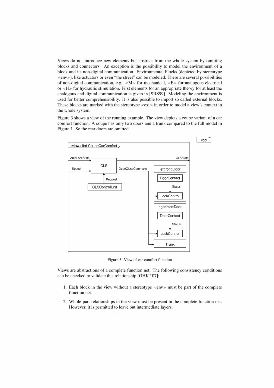
Figure 7: Alternative features
contain the relevant information for the examples.
Alternative Features
Figure 7 shows a feature with its two alternatives subfeatures S1 and S2. The figure alsodepicts the underlying (150 percent) feature model that is the basis for the two alternatives.Also, all possible variants are shown which, in case of alternatives, coincide with thesubfeature views.
We assume that each block has an incoming signal I. Block A has an outgoing signal X,and so on. As motivated later, the complete model still has to be a valid function net inwhich each signal has exactly one sender, so sharing outgoing connectors is not allowed.Some outgoing signals are only used in one variant. Now, this could mean two things, a)the signals actually have the same signal type and semantics but since it is not possibleto have the same signal name with multiple senders, different signal names have to beinvented, or b) the signals are not connected in any way. While b) is not a problem,in case a) one could argue that the logical architecture should preserve this information.This could, for instance, be achieved by adding another logical block to the architecturethat receives three distinct signals and delegates one common signal. Another possibility

Figure 8: Or-features
would be to add signal types and instances to the function nets.
Or-Features
Figure 8 depicts a feature that may consist of subfeatures S1 or S2 or both of them. As inour previous example we assume that we have an incoming signal I and outgoing signalsX, Y. In variant vS1S2 both subfeatures (S1 and S2) are active. So both, X and Y, aresent by Feature2. Again, if X and Y are only different names for (conceptually) the samesignal, the receiving blocks or functions have to consider this. In that case, if both signalstarget at the same function, additional mechanisms (e.g., an arbiter) could be inserted.
Mandatory and optional features
In addition to alternative and or-features we have the composition of subfeatures. In thissituation, a subfeature can be mandatory or optional. Figure 9 shows an optional featureS1 and a mandatory feature S2. We assume that we have I as an incoming signal. BlockA has an outgoing signal X and B has an outgoing signal Y. The given feature diagramimplies two valid variants as seen in our variant views: The variant in which only B isactive and another variant in which A and B are active.
Note that there are more combinations of features possible. The basic elements of thenotation were introduced here. In [CE00] the normalization of feature combinations isexplained in detail.

Figure 9: Mandatory and optional features
4 Methodological Aspects
View-based development of an automotive logical architecture can be integrated in a typ-ical automotive development process as described in [GHK+07, GHK+08]. Some addi-tional methodological aspects are discussed below.
Developing Automotive Systems
With this approach we want to introduce an extended methodology and tool chain, thatuses an intermediate layer to describe the logical architecture using function nets. Thisintermediate layer in between the requirements and the implementation phases improvesthe understandability of automotive systems by focusing on feature modeling and increasesreusability.
The features of a system are extracted from requirements that were captured using a re-quirements management system, e.g., DOORS [Tel08]. The logical architecture is de-veloped by using function nets. The features from requirements are mapped to the logicalarchitecture by feature views. For a better comprehensibility and to abstract from the com-plete “150 percent model”, feature diagrams and variant views are used. In subsequentdevelopment steps the logical architecture can be mapped to a realization, e.g., using the

AUTOSAR [Aut08] methodology.
Automotive systems are not developed from scratch. A new generation of a system isusually based on its predecessor. Being able to reuse large parts of a logical architecture(not just implementations as proposed by AUTOSAR) is hence a key requirement. This issupported by our approach in that the complete logical architecture and feature views canbe used as a starting point for the development of the next vehicle generation. Changes aremade to the views to fullfil new requirements. Consistency to the complete model is thenchecked and possible conflicts and inconsistencies can be tracked down automatically andresolved manually since this in general is a complex engineering task.
We hence propose the following development steps to model a logical architecture:
1. Create or adapt feature diagrams.
2. Reuse the complete logical architecture and views from an earlier vehicle genera-tion.
3. Develop self-contained views to describe new features.
4. Adapt feature views to reflect changes in the requirements specifications.
5. Early and repeatedly execute consistency checks between views and the completefunction net of a predecessor to identify inconsistencies or unused blocks in orderto modify the complete function net.
Advantages and Limitations of a 150 percent model
When developing complete systems, like cars, we can safely assume that at some point thecomplete system architecture is developed including all possible variations. The so called150 percent model of an architecture constitutes the basis for modeling system configura-tions with views. Especially in the automotive domain it is not feasible to generate and testevery possible variant configuration. As a consequence, analysis, verification, and testingof an automotive logical architecture can much better be carried out on this 150 percentmodel that integrates all variants. Therefore, we need the complete logical architectureto be a valid function net (e.g., with one sender per signal only). This however does notmean that we cannot run tests on incomplete models or views. Quite the contrary: It ismandatory to clarify certain functional and non-functional properties early on views andreuse these tests for complete function nets.
Top-down vs. bottom-up development
The development process in general could be a top-down, a bottom-up process or a combi-nation of both. In a top-down process the logical architecture is modeled on a high level of
abstraction and later each element is refined until it has the desired structure. In a bottom-up process modeling stays very close to an implementation. The concept of views canbe used to hide the complexity of such an architecture. Today, in the automotive sectormost software is designed from bottom-up. One reason is that the placement of a logicalfunction is often already decided because the ECU that is realizing this function is alreadypredetermined. Reuse of system components is not limited to the logical architecture,but is also an aspect on the hardware level. To consider already fixed design decisions,function nets can be equipped with attributes that document these decisions early in thedevelopment process [GHK+07].
However, a stringent use of views on function nets can lead to a substantial change ofmethod, as it will be possible to model functional units and assemble them at will. Thusfunction nets can be developed top-down, bottom-up or even starting in the middle. Fur-thermore, it will be possible to evolve function nets using calculi like [KR06, PR97,PR99]. Consequently, modeling architectures with function nets and views supports both,top-down and bottom-up modeling. In practice, we assume a mixture of both wherenew requirements are propagated top-down through the logical architecture that is reused“bottom-up” from an earlier vehicle generation.
5 Related Work
In [CE00] the modeling of features is described using a tree-based notation. This notationis widespread and intuitive. This paper adapts the notation of feature diagrams to modelfeatures of automotive systems.
An important concept of handling variability in software systems is introduced in [PBvdL05].The authors explain how variability of system can be handled as so called product lines.A notation to model the variation points and the variants of a system is introduced. Wedecided to follow the notation in [CE00] because in our opinion it is more intuitive andoften used.
An approach to model the logical architecture of automotive systems with UML-RT isintroduced in [vdB04]. This approach is extended by using internal block diagrams fromSysML [OMG06] to model logical architectures and views.
In [SE06] the possibility of merging views to a complete system are discussed. Mergingviews to a complete system could be interesting in a strict top-down development process.Nevertheless, we do not propose to merge views because of constant evolution of require-ments. Checking consistency between views and a complete function net eases findinginconsistencies that have to be resolved manually.
In AML [vdBBFR03, vdBBRS02] functions are tailored by introducing a variant depen-dency in class diagrams. AML uses a strict top-down design of functions. In our approach,logical functions can be shared across multiple features and also variants.
The automated derivation of the product variants of a software product line are explainedin [BD07]. The derivation is illustrated by an example product line of meteorological data

systems. As notation a simplified variant of feature diagrams from [CE00] is used.
AUTOSAR [Aut08] is a consortium that standardizes the architecture of automotive sys-tems and improves the reuse of software components. Our approach proposes the AU-TOSAR methodology to realize a given function net. But we think it is necessary tohave an intermediate layer in between requirements and AUTOSAR to improve the un-derstandability and the reuse of automotive features. Our approach of modeling logicalarchitectures with function nets fills out this gap.
6 Conclusion
In [GHK+07, GHK+08] a notation to model logical architectures as function nets is intro-duced that fills the gap between requirements and the realization of automotive systems.Based on that notation, the concept of views was explained using the same notation. In thispaper the concept was extended to model variants of an architecture. In combination withfeature diagrams, feature views and variant views are used to communicate variability ofautomotive system architectures.
Especially in developing software for automotive systems the explicit modeling and anefficient handling of the high diversity of configurations is important. The variability of asystem is mapped from requirements to the logical architecture using views. From therethe variability can be mapped on a concrete realization, for instance with help of the AU-TOSAR methodology.
Generally, tool support is a fundamental aspect of modeling architectures. So, in futurework the tool support has to be extended. With the extension of the tool chain, we thinkour approach helps to handle variability and complexity of automotive systems in existingdevelopment processes. In the future, we also will investigate how the approach can beextended by models that describe the behavior of a feature.
References
[Aut08] Autosar website http://www.autosar.org, January 2008.
[BD07] Danilo Beuche and Mark Dalgarno. Software Product Line Engineering with FeatureModels. Overload Journal, 78:5–8, 2007.
[CE00] Krzysztof Czarnecki and Ulrich W. Eisenecker. Generative Programming: Methods,Tools, and Applications. Addison-Wesley, 2000.
[GHK+07] Hans Gronniger, Jochen Hartmann, Holger Krahn, Stefan Kriebel, and BernhardRumpe. View-Based Modeling of Function Nets. In Proceedings of the Object-oriented Modelling of Embedded Real-Time Systems (OMER4) Workshop, pages 40–45, October 2007.

[GHK+08] Hans Gronniger, Jochen Hartmann, Holger Krahn, Stefan Kriebel, Lutz Rothhardt,and Bernhard Rumpe. Modelling Automotive Function Nets with Views for Features,Variants, and Modes. In Proceedings of ERTS 2008, 2008.
[KR06] H. Krahn and B. Rumpe. Handbuch der Software-Architektur, chapter Grundlagender Evolution von Software-Architekturen, pages 133–151. dpunkt-Verlag, 2006.
[OMG06] Object Management Group. SysML Specification Version 1.0 (2006-05-03), August2006. http://www.omg.org/docs/ptc/06-05-04.pdf.
[PBvdL05] Klaus Pohl, Gunter Bockle, and Frank van der Linden. Software Product Line Engi-neering: Foundations, Principles, and Techniques. Springer, 2005.
[PR97] Jan Philipps and Bernhard Rumpe. Refinement of Information Flow Architectures. InProceedings of Formal Engineering Methods, 1997.
[PR99] Jan Philipps and Bernhard Rumpe. Refinement of Pipe And Filter Architectures. InFM’99, LNCS 1708, pages 96–115, 1999.
[SE06] Mehrdad Sabetzadeh and Steve Easterbrook. View merging in the presence of incom-pleteness and inconsistency. Requir. Eng., 11(3):174–193, 2006.
[SRS99] Thomas Stauner, Bernhard Rumpe, and Peter Scholz. Hybrid System Model. Techni-cal Report TUM-I9903, Technische Univeritat Munchen, 1999.
[Tel08] Telelogic DOORS website http://www.telelogic.com/products/doors/,January 2008.
[vdB04] Michael von der Beeck. Function Net Modeling with UML-RT: Experiences from anAutomotive Project at BMW Group. In UML Satellite Activities, pages 94–104, 2004.
[vdB06] Michael von der Beeck. A Formal Semantics of UML-RT. In Proceedings of MoDELS2006(LNCS 4199), pages 768–782, 2006.
[vdBBFR03] Michael von der Beeck, Peter Braun, Ulrich Freund, and Martin Rappl. ArchitectureCentric Modeling of Automotive Control Software. In SAE Technical Paper Series2003-01-0856, 2003.
[vdBBRS02] Michael von der Beeck, Peter Braun, Martin Rappl, and Christian Schroder. Auto-motive Software Development: A Model Based Approach. In World Congress ofAutomotive Engineers, SAE Technical Paper Series 2002-01-0875, 2002.
Related Documents