1 Modeling the Elastic Modulus of 2D Woven CVI SiC Composites Gregory N. Morscher 1 , Ohio Aerospace Institute, Brookpark, OH ABSTRACT The use of fiber, interphase, CVI SiC minicomposites as structural elements for 2D-woven SiC fiber reinforced chemically vapor infiltrated (CVI) SiC matrix composites is demonstrated to be a viable approach to model the elastic modulus of these composite systems when tensile loaded in an orthogonal direction. The 0 o (loading direction) and 90 o (perpendicular to loading direction) oriented minicomposites as well as the open porosity and excess SiC associated with CVI SiC composites were all modeled as parallel elements using simple Rule of Mixtures techniques. Excellent agreement for a variety of 2D woven Hi-Nicalon TM fiber-reinforced and Sylramic-iBN reinforced CVI SiC matrix composites that differed in numbers of plies, constituent content, thickness, density, and number of woven tows in either direction (i.e, balanced weaves versus unbalanced weaves) was achieved. It was found that elastic modulus was not only dependent on constituent content, but also the degree to which 90 o minicomposites carried load. This depended on the degree of interaction between 90 o and 0 o minicomposites which was quantified to some extent by composite density. The relationships developed here for elastic modulus only necessitated the knowledge of the fractional contents of fiber, interphase and CVI SiC as well as the tow size and shape. It was concluded that such relationships are fairly robust for orthogonally loaded 2D woven CVI SiC composite system and can be implemented by ceramic matrix composite component modelers and designers for modeling the local stiffness in simple or complex parts fabricated with variable constituent contents. INTRODUCTION Woven silicon carbide fiber reinforced silicon carbide matrix composites with matrices fabricated by the chemical vapor infiltration route represent a very important 1 Senior research scientist residing at NASA Glenn Research Center, Cleveland, OH

Welcome message from author
This document is posted to help you gain knowledge. Please leave a comment to let me know what you think about it! Share it to your friends and learn new things together.
Transcript
1
Modeling the Elastic Modulus of 2D Woven CVI SiC Composites
Gregory N. Morscher1, Ohio Aerospace Institute, Brookpark, OH
ABSTRACT
The use of fiber, interphase, CVI SiC minicomposites as structural elements for
2D-woven SiC fiber reinforced chemically vapor infiltrated (CVI) SiC matrix composites
is demonstrated to be a viable approach to model the elastic modulus of these composite
systems when tensile loaded in an orthogonal direction. The 0o (loading direction) and
90o (perpendicular to loading direction) oriented minicomposites as well as the open
porosity and excess SiC associated with CVI SiC composites were all modeled as parallel
elements using simple Rule of Mixtures techniques. Excellent agreement for a variety of
2D woven Hi-NicalonTM fiber-reinforced and Sylramic-iBN reinforced CVI SiC matrix
composites that differed in numbers of plies, constituent content, thickness, density, and
number of woven tows in either direction (i.e, balanced weaves versus unbalanced
weaves) was achieved. It was found that elastic modulus was not only dependent on
constituent content, but also the degree to which 90o minicomposites carried load. This
depended on the degree of interaction between 90o and 0o minicomposites which was
quantified to some extent by composite density. The relationships developed here for
elastic modulus only necessitated the knowledge of the fractional contents of fiber,
interphase and CVI SiC as well as the tow size and shape. It was concluded that such
relationships are fairly robust for orthogonally loaded 2D woven CVI SiC composite
system and can be implemented by ceramic matrix composite component modelers and
designers for modeling the local stiffness in simple or complex parts fabricated with
variable constituent contents.
INTRODUCTION
Woven silicon carbide fiber reinforced silicon carbide matrix composites with
matrices fabricated by the chemical vapor infiltration route represent a very important
1 Senior research scientist residing at NASA Glenn Research Center, Cleveland, OH
2
class of materials for a variety of high temperature air-breathing, space, and nuclear
applications [1]. Future SiC/SiC components will possess rather complex shapes
requiring various architectures, differences in local thickness, and local curvature, which
may also lead to processing non-uniformities throughout a given component. Needless to
say, in order to design with such materials, the effect of geometry, fiber-orientation,
architecture, and constituent properties and content on stress-strain response needs to be
well understood. The first and the foremost property required for component design is the
effect of these factors on tensile elastic modulus. A significant amount of work has been
performed towards understanding the mechanical properties of 2D [2-8] and 3D [5]
woven CVI SiC matrix composites primarily with regard to the occurrence of non-linear
stress-strain behavior due to matrix cracking. However, little has been done to quantify
the elastic properties of these composites as a function of architecture, constituent
properties, and constituent content. Therefore, the objective of this study was to
determine relationships for the elastic modulus of 0/90 2D woven CVI SiC composites in
the orthogonal directions for a wide variety of composite parameters by carefully
accounting for all those parameters. The parameters included architectural variations,
which included composite thickness, number of plies, balanced and unbalanced weaves,
and tow size, and constituent variations, which included fiber-type, interphase
composition, and constituent contents. In a companion paper [9], the effects of these
same architectural and compositional parameters on matrix cracking were studied.
EXPERIMENTAL
Composite specimens with different CVI SiC matrix content were obtained from
several processing approaches/anomalies representing vintages that span over 10 years
from the same vendor (currently General Electric Power Systems Composite, Newark,
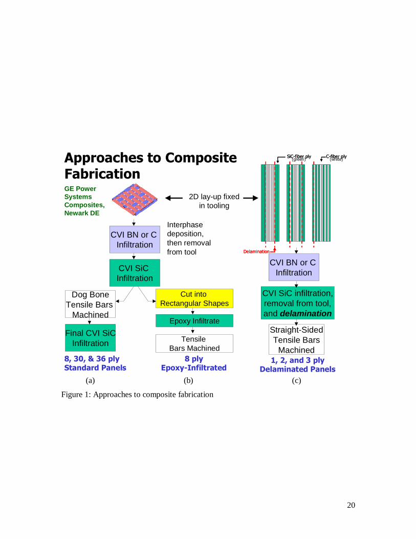
DE). The three general processing approaches are shown schematically in Figure 1 and
indicated in Table I. “Standard specimens” went through typical CVI fabrication and
machining at General Electric Power Systems Composites, Newark, DE (Figure 1a). This
consisted of woven fiber lay-up, CVI interphase infiltration, initial CVI SiC infiltration,
specimen machining and a final CVI SiC infiltration step to further densify the specimen.
Specimens consisting of eight to 36 plies were fabricated in this manner. Some
3
specimens, consisting of eight plies, were infiltrated to less than “full” matrix content (~
50%) and not subjected to final CVI SiC infiltration. The open porosity in these low
density matrices was filled with epoxy [10] (Figure 1b) for subsequent mechanical
testing. In other studies, this fiber-interphase-CVI SiC “preform” makes up the skeleton
of higher density composites where the open porosities are filled by SiC slurry and melt-
infiltrated silicon composites [11]. However, for the purpose of this study they represent
a very low CVI SiC content composite since the epoxy carries negligible mechanical
loads. The third set of specimens were “thin panels” that consisted of one, two, or three
plies that had delaminated from a multilayer woven SiC fiber, carbon fiber preform
during CVI SiC infiltration [12] (Figure 1c). Even though these specimens were the
product of delamination, the delamination occurred early in processing, so that cracking
of CVI the SiC matrix was not observed in polished as-produced specimens.
As indicated in Table I, constituent variations included the woven fiber-type and
interphase composition. Composites were fabricated with Hi-NicalonTM (HN) fibers
(Nippon Carbon, Japan) woven at 6.7 tow ends per cm as a balanced five-harness satin or
eight-harness satin weave or Sylramic-iBN fibers (Dow Corning, Midland, MI with a
special NASA treatment [13]) woven into balanced (7.9 epcm) or unbalanced (9.4 epcm
x 5.5 epcm) five-harness satin pieces of cloth. Fiber-preforms were either infiltrated with
C or BN as the interphase. Specimens were machined as dog-bone specimens or straight-
sided specimens, Table I identifies the specimen geometry of each specimen.
The constituent content was determined for each individual specimen from the
mass of the specimens and relative weight gain information obtained from the composite
manufacturer. This was necessary because CVI SiC content varies across a panel and
some of the specimens were further densified after specimen machining. First, the mass
of the as-processed and as-cut specimen was determined*. The dimensions were
measured for each specimen shape to determine the specimen volume. The density was
* The mass for each specimen was determined in the as-machined ready-to-test state with the exception of
the epoxy-infiltrated specimens. The epoxy-infiltrated specimens were weighed after the perform panel was
cut into straight-sided specimens and prior to epoxy-infiltration and dogbone machining for constituent
determination. The weight of the after-epoxy specimen was measured as well.
4
determined for each specimen from the mass and specimen volume. The average total
fiber volume fraction was determined from the fiber tow and weave properties as follows:
t
epmmepmmRNNf ffply
f900
2
(1)
where Nply is the number of woven plies, Nf is the number of fibers per tow (500 for Hi-
Nicalon and 800 for Sylramic-iBN), Rf is the average fiber radius (0.00685 m for Hi-
Nicalon and 0.005 m for Syl-iBN as measured from polished cross-sections of several
composites), t is the average specimen thickness, and epmm is the number of tow ends
per mm, and subscripts 0 and 90 refer to the orthogonal directions
The fraction of the interphase material, fi, was determined as follows:
if
fifi m
mff
(2)
where mf is the mass of the fiber preform before tooling, mi is the mass of the interphase
by subtracting the mass of the interphase coated preform from the fiber-only preform
mass, and f and i are the densities of the fiber (2.71 g/cc for Hi-Nicalon and 3.05 g/cc
for Sylramic-iBN) and interphase, respectively. The density of the interphase was
assumed to be 1.5 g/cc for BN [14] and C. This value may be in error; however, fi is
relatively insensitive to the analysis below. The CVI SiC volume was then determined as
follows:
iiffspecSiC
specSiC ff
VV
(3)
where Vspec is the specimen volume, spec is the specimen density, and SiC is the density
of CVI SiC (3.2 g/cc). The volume fraction of SiC matrix, fSiC, is then simply VSiC/Vspec.
Finally, the average total fraction of porosity for each specimen could be estimated from
the constituent volume fractions:
5
SiCifp ffff 1 (4)
The constituent fractions are listed in Table I.
Room temperature tensile testing was performed using a universal-testing
machine (Instron 8562, Instron Ltd., Canton, Mass.) and strain was measured with a clip-
on extensometer (2.5% maximum strain range over a 25.4 mm gage length). For some of
the tensile tests, three wide-band acoustic emission (AE) sensors were attached to the
specimen, which is described in the companion paper [9]. Specimens were either tested
monotonically to failure or were loaded, unloaded, and reloaded at a higher load until
failure occurred. The loading rate was 2 kN/min for the thin specimens, 4 kN/min for
standard specimens, and 10 kN/min for the thick specimens.
RESULTS
The composites differ considerably in numbers of plies (1 to 36), thickness (0.38
to 10.6 mm), and constituent content (Table I). Most notably, fSiC varied by nearly a
factor of two and fp varied by nearly a factor of three for the Hi-Nicalon composites.
There was also significant variation in ff and some composites fabricated with a carbon
interphase for each fiber-type had significantly higher interphase content than the other
specimens (Table I).
Microstructure
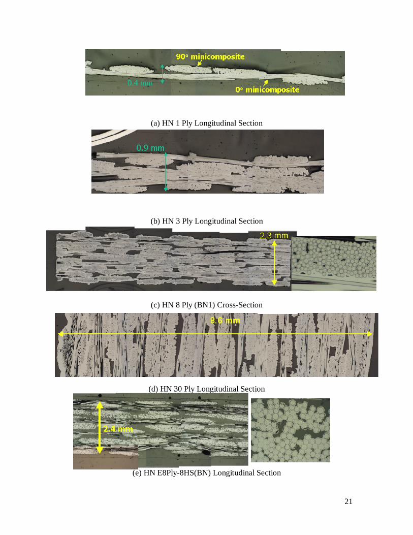
Some of the composite microstructures are shown in Figure 2 for HN composites
(a-g) and SYL-iBN composites (f-i). Longitudinal sections refer to sections cut and
polished along the length of the tensile specimen, whereas the cross section (Figure 2c)
refers to the section cut perpendicular to the length of the tensile specimen. The
microstructure differs considerably. For the thick specimens (Figure 2d), the exterior
plies have a high CVI SiC content whereas the inner plies have larger unfilled regions,
typical of preferential SiC deposition. For the epoxy-infiltrated high-porosity specimens
(Figure 2e), the structure is very open. Note how nearly all the coated tows are separate
from one another. Noted in Figure 2a is the 0o minicomposite, i.e., the region of fiber,
interphase, and CVI SiC matrix oriented in the loading direction, and the 90o
6
minicomposite, i.e., the region of fiber, interphase, and CVI SiC matrix oriented
perpendicular to the loading direction. This will become important later in the analysis.
Also, the effect of fiber-type results in different tow sizes which is a product of the
weave, compaction of the ply lay-up by the manufacturer, total fiber count and fiber
diameter. The cross-sectional area of fibers in a Hi-Nicalon tow is about 22.5% greater
than the Sylramic-iBN tow. Note also that some axially-oriented porosity exists within
the tows.
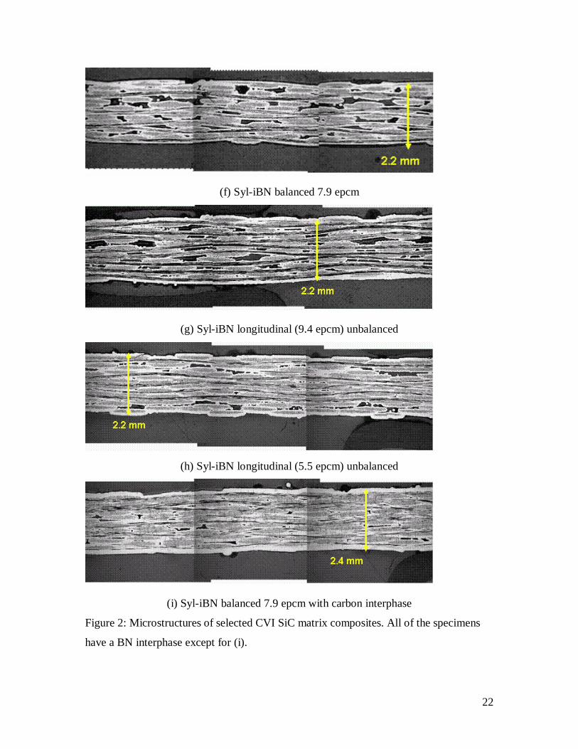
Stress-Strain Behavior and Ultimate Failure
Room-temperature stress-strain curves obtained by tensile loading along the fiber
orthogonal directions are shown in Figure 3 for the different composite systems. As
expected, the composites with the lowest porosities had relatively high elastic moduli,
whereas the specimens with the highest porosities (epoxy-infiltrated and thin panels) had
lower elastic moduli. There was also much variation in non-linear stress-strain behavior
and ultimate tensile strength which will be discussed and analyzed in the companion
paper [9].
Elastic Modulus and Speed of Sound of Undamaged Composites
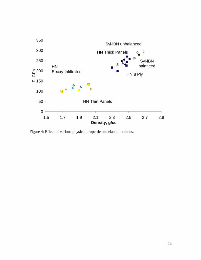
The effect of constituent content on elastic modulus was analyzed for a variety of
constituents and physical parameters. On an empirical basis, composite modulus proved
to exhibit the best correlation with composite density (Figure 4). There appears to be two
regions, a region of higher density where there is a strong relationship between density
and E and a lower density region where there is a mild relationship between density and
E.
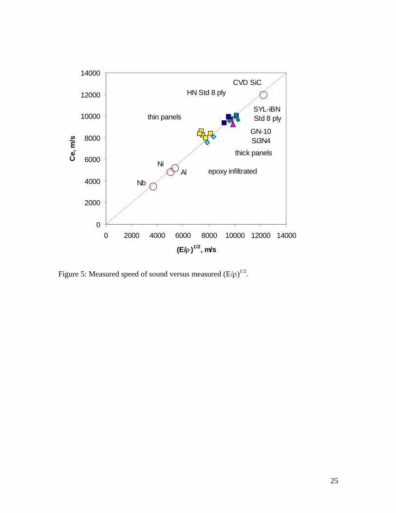
The speed of sound of each specimen was used as a check to the measurements of
E and Sound waves were created by pencil lead-breaks or by the matrix microfractures
that occur near or in the grips at very low loads [9]. The speed of sound could be
determined from the difference in time of arrival of the first peak of the relatively non-
dispersive extensional wave [15]. Figure 5 shows a plot of speed of sound versus
(E/for a number of monolithic materials and the composites tested in this study Note
that under plane strain behavior, it would be proper to compare the measured elastic
7
moduli with (E/[, where is Poisson’s ratio. However, was not known for
the composites and was assumed to have a minor affect on the analysis since would be
~ 0.2 + 0.1. The speeds of sound of the monoliths fall just below a line of direct
proportion, due to the absence of in the comparison. The speeds of sound of the
composites fall near the same line indicating a good correlation of measured elastic
modulus and density.
Modeling Elastic Modulus: The Role of the 90o Minicomposite
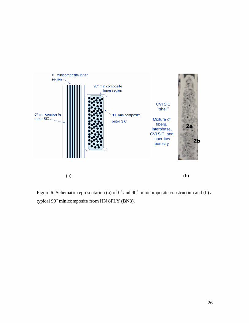
Similar to reference 6, the entire composite can be considered to consist of 0o
(stressed direction) and 90o (perpendicular to stress direction) oriented fiber-interphase-
CVI SiC minicomposites. In this construction, the minicomposite is not necessarily a
uniform mixture, unlike 0/90 laminate composites [16-17], but may contain two distinct
regions: an inner region consisting of a mixture of fibers, interphase coating, CVI SiC
and inner-tow porosity surrounded by an outer “shell” of CVI SiC if a sufficient amount
of SiC is infiltrated to fill the inner region (Figure 6a and b). In addition, there are
typically large open pores associated with weave crossover points and depends on the
degree of “nesting” achieved after ply stacking and pressing.
The difficulty in modeling the elastic modulus of woven composites comes with
the treatment of the 90o minicomposites and the network of open porosity. The large open
porosity in composites is sometimes associated with 0o minicomposites and can be
considered in parallel to the loading direction; however, some large pores are associated
with the 90o minicomposites and would appear to be in series in a given ply. The large
pores associated with the 90o plies would increase as epcm decreases for the 90o
orientation. On the other hand, nesting, ply compaction, and the registry of ply lay-up can
minimize the porosity within and between plies. Also, if the porosity is on average well-
distributed in a cross-section and good transfer of load exists between 0o and 90o
minicomposites over a critical length scale in the loading direction, it is possible that all
of the open porosity can be treated in parallel. The approach here will be to determine in
general the degree of load carried by the 90o minicomposites assuming that all of the
large open porosity acts in parallel under load. Then a model for the elastic modulus of
8
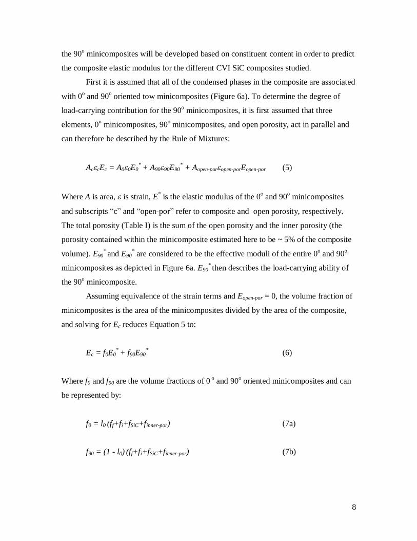
the 90o minicomposites will be developed based on constituent content in order to predict
the composite elastic modulus for the different CVI SiC composites studied.
First it is assumed that all of the condensed phases in the composite are associated
with 0o and 90o oriented tow minicomposites (Figure 6a). To determine the degree of
load-carrying contribution for the 90o minicomposites, it is first assumed that three
elements, 0o minicomposites, 90o minicomposites, and open porosity, act in parallel and
can therefore be described by the Rule of Mixtures:
AccEc = A00E0* + A9090E90
* + Aopen-poropen-porEopen-por (5)
Where A is area, is strain, E* is the elastic modulus of the 0o and 90o minicomposites
and subscripts “c” and “open-por” refer to composite and open porosity, respectively.
The total porosity (Table I) is the sum of the open porosity and the inner porosity (the
porosity contained within the minicomposite estimated here to be ~ 5% of the composite
volume). E90* and E90
* are considered to be the effective moduli of the entire 0o and 90o
minicomposites as depicted in Figure 6a. E90* then describes the load-carrying ability of
the 90o minicomposite.
Assuming equivalence of the strain terms and Eopen-por = 0, the volume fraction of
minicomposites is the area of the minicomposites divided by the area of the composite,
and solving for Ec reduces Equation 5 to:
Ec = f0E0* + f90E90
* (6)
Where f0 and f90 are the volume fractions of 0 o and 90o oriented minicomposites and can
be represented by:
f0 = l0 (ff+fi+fSiC+finner-por) (7a)
f90 = (1 - l0) (ff+fi+fSiC+finner-por) (7b)
9
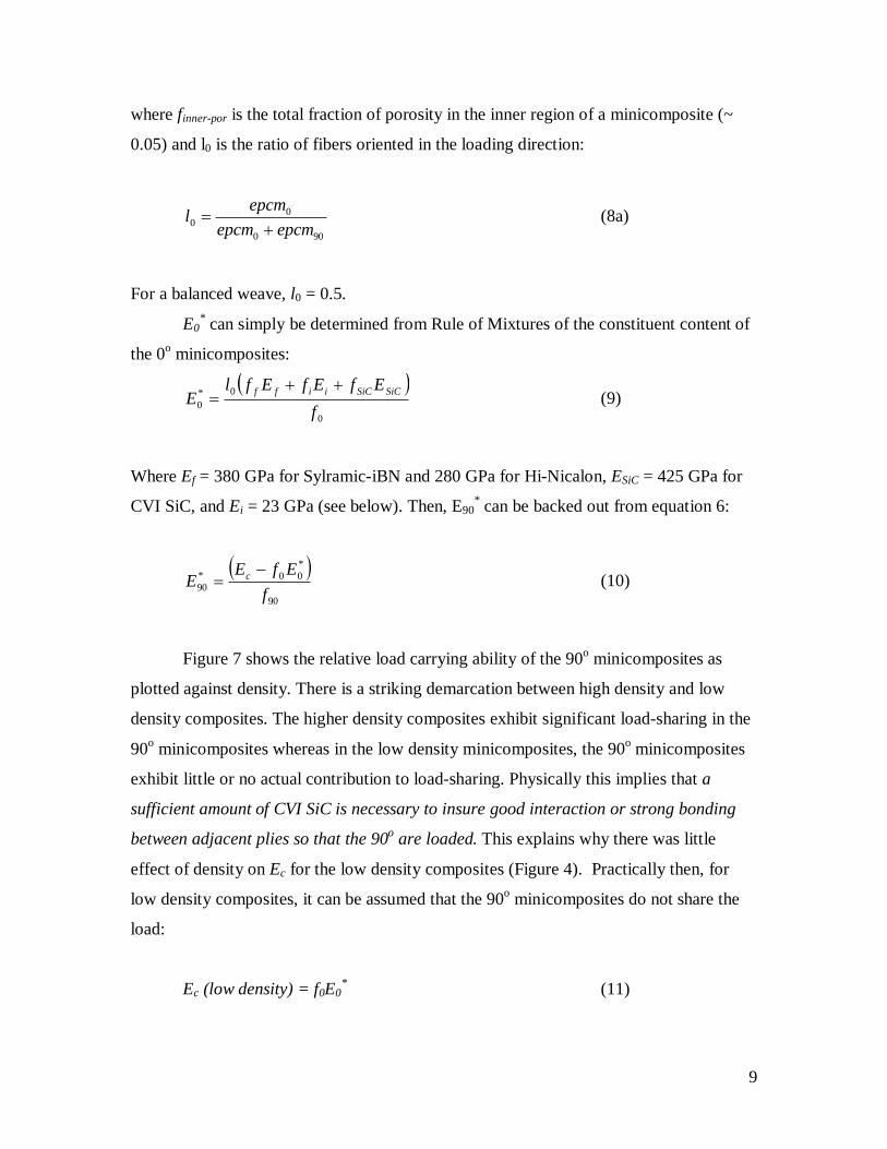
where finner-por is the total fraction of porosity in the inner region of a minicomposite (~
0.05) and l0 is the ratio of fibers oriented in the loading direction:
900
00 epcmepcm
epcml
(8a)
For a balanced weave, l0 = 0.5.
E0* can simply be determined from Rule of Mixtures of the constituent content of
the 0o minicomposites:
0
0*0 f
EfEfEflE SiCSiCiiff
(9)
Where Ef = 380 GPa for Sylramic-iBN and 280 GPa for Hi-Nicalon, ESiC = 425 GPa for
CVI SiC, and Ei = 23 GPa (see below). Then, E90* can be backed out from equation 6:
90
*00*
90 fEfE
E c (10)
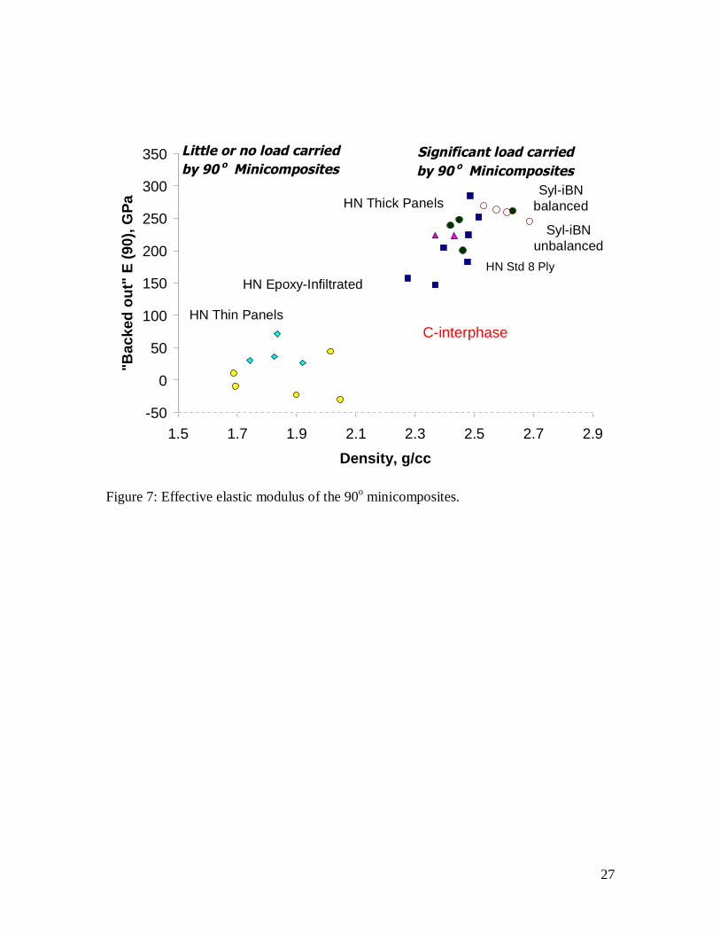
Figure 7 shows the relative load carrying ability of the 90o minicomposites as
plotted against density. There is a striking demarcation between high density and low
density composites. The higher density composites exhibit significant load-sharing in the
90o minicomposites whereas in the low density minicomposites, the 90o minicomposites
exhibit little or no actual contribution to load-sharing. Physically this implies that a
sufficient amount of CVI SiC is necessary to insure good interaction or strong bonding
between adjacent plies so that the 90o are loaded. This explains why there was little
effect of density on Ec for the low density composites (Figure 4). Practically then, for
low density composites, it can be assumed that the 90o minicomposites do not share the
load:
Ec (low density) = f0E0* (11)
10
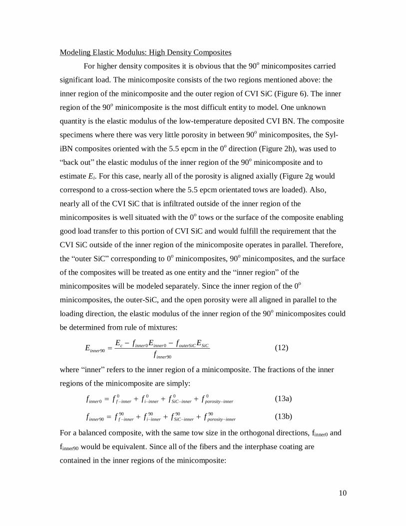
Modeling Elastic Modulus: High Density Composites
For higher density composites it is obvious that the 90o minicomposites carried
significant load. The minicomposite consists of the two regions mentioned above: the
inner region of the minicomposite and the outer region of CVI SiC (Figure 6). The inner
region of the 90o minicomposite is the most difficult entity to model. One unknown
quantity is the elastic modulus of the low-temperature deposited CVI BN. The composite
specimens where there was very little porosity in between 90o minicomposites, the Syl-
iBN composites oriented with the 5.5 epcm in the 0o direction (Figure 2h), was used to
“back out” the elastic modulus of the inner region of the 90o minicomposite and to
estimate Ei. For this case, nearly all of the porosity is aligned axially (Figure 2g would
correspond to a cross-section where the 5.5 epcm orientated tows are loaded). Also,
nearly all of the CVI SiC that is infiltrated outside of the inner region of the
minicomposites is well situated with the 0o tows or the surface of the composite enabling
good load transfer to this portion of CVI SiC and would fulfill the requirement that the
CVI SiC outside of the inner region of the minicomposite operates in parallel. Therefore,
the “outer SiC” corresponding to 0o minicomposites, 90o minicomposites, and the surface
of the composites will be treated as one entity and the “inner region” of the
minicomposites will be modeled separately. Since the inner region of the 0o
minicomposites, the outer-SiC, and the open porosity were all aligned in parallel to the
loading direction, the elastic modulus of the inner region of the 90o minicomposites could
be determined from rule of mixtures:
90
0090
inner
SiCouterSiCinnerinnercinner f
EfEfEE
(12)
where “inner” refers to the inner region of a minicomposite. The fractions of the inner
regions of the minicomposite are simply:0000
0 innerporosityinnerSiCinneriinnerfinner fffff (13a)
9090909090 innerporosityinnerSiCinneriinnerfinner fffff (13b)
For a balanced composite, with the same tow size in the orthogonal directions, finner0 and
finner90 would be equivalent. Since all of the fibers and the interphase coating are
contained in the inner regions of the minicomposite:
11
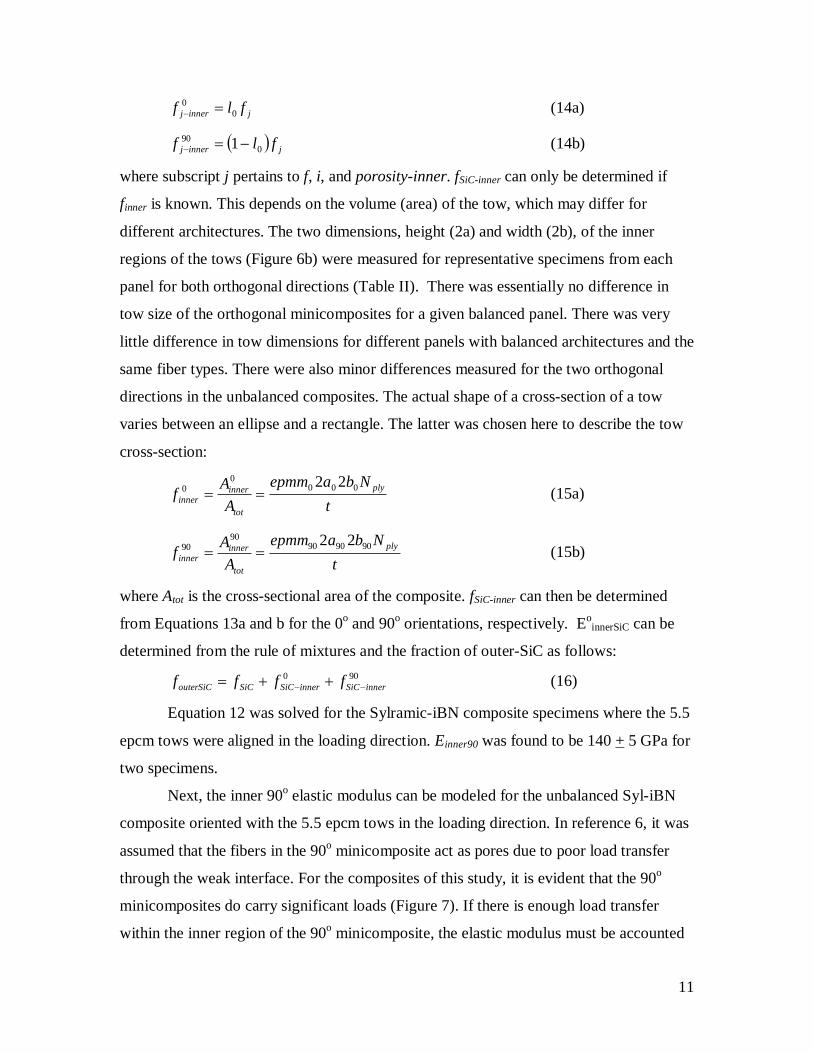
jinnerj flf 00 (14a)
jinnerj flf 090 1 (14b)
where subscript j pertains to f, i, and porosity-inner. fSiC-inner can only be determined if
finner is known. This depends on the volume (area) of the tow, which may differ for
different architectures. The two dimensions, height (2a) and width (2b), of the inner
regions of the tows (Figure 6b) were measured for representative specimens from each
panel for both orthogonal directions (Table II). There was essentially no difference in
tow size of the orthogonal minicomposites for a given balanced panel. There was very
little difference in tow dimensions for different panels with balanced architectures and the
same fiber types. There were also minor differences measured for the two orthogonal
directions in the unbalanced composites. The actual shape of a cross-section of a tow
varies between an ellipse and a rectangle. The latter was chosen here to describe the tow
cross-section:
t
Nbaepmm
AA
f ply
tot
innerinner
0000
0 22 (15a)
t
Nbaepmm
AA
f ply
tot
innerinner
90909090
90 22 (15b)
where Atot is the cross-sectional area of the composite. fSiC-inner can then be determined
from Equations 13a and b for the 0o and 90o orientations, respectively. EoinnerSiC can be
determined from the rule of mixtures and the fraction of outer-SiC as follows:900
innerSiCinnerSiCSiCouterSiC ffff (16)
Equation 12 was solved for the Sylramic-iBN composite specimens where the 5.5
epcm tows were aligned in the loading direction. Einner90 was found to be 140 + 5 GPa for
two specimens.
Next, the inner 90o elastic modulus can be modeled for the unbalanced Syl-iBN
composite oriented with the 5.5 epcm tows in the loading direction. In reference 6, it was
assumed that the fibers in the 90o minicomposite act as pores due to poor load transfer
through the weak interface. For the composites of this study, it is evident that the 90o
minicomposites do carry significant loads (Figure 7). If there is enough load transfer
within the inner region of the 90o minicomposite, the elastic modulus must be accounted
12
for. However, Ei of BN deposited at low temperatures is not well understood. In another
study, it was assumed that the elastic modulus of the nanocrystalline randomly oriented
BN was 62 GPa [14]. The elastic modulus of low temperature derived BN ranges from 10
to 200 GPa [18-20] depending on orientation and crystallinity. Since Einner90 was
estimated for the composites with the 5.5 epcm tows oriented in the loading direction, a
simple Reuss element (Equation 17) was used to model Einn90 from which Ei could be
backed out. The best fit Ei equaled 23 GPa. This value corresponds well with the elastic
modulus of BN (20 GPa) in similar composites measured by nanoindentation [21].1
90
SiC
innerSiC
f
finner
i
iinnerinner E
fE
f
Ef
E (17)
Finally, the same approach and assumptions (0o inner minicomposite, outer SiC,
macroporosity, and 90o inner minicomposite all act in parallel) were applied to model the
elastic modulus of all the higher density composites. Two extremes were modeled for
Einner90. The high stiffness extreme used Equation 17 to estimate Einner90 with Ei assumed
to be 23 GPa. The low stiffness extreme assumed Einner90 = 0, i.e., poor load-transfer or
fiber-matrix decoupling within the inner region of the minicomposite. The Rule of
Mixtures relationship, Equation 12 (solved for Ec), was used to determine Ec. Figure 8
plots the measured Ec vs the predicted Ec for the Sylramic-iBN and Hi-Nicalon composite
systems. For the lower density Hi-Nicalon composites, Equation 11 was used to predict
Ec. Table III lists the measured and estimated moduli for each specimen.
There is excellent agreement between predicted and measured Ec for the
Sylramic-iBN composites regardless of interphase or orientation when using the Reuss
model to describe Einner90. The Hi-Nicalon composites are in good agreement for the
Reuss model; however, the predicted Ec tended to overestimate the measured value. The
lower extreme prediction, Einner90 = 0, underestimated the measured Ec for all the higher
density composites except for the 8 ply carbon interphase Hi-Nicalon CVI SiC.
DISCUSSION:
The elastic modulus of the CVI SiC matrix composites was predicted by applying
simple Rule of Mixture techniques for a wide range of constituent content, ply lay up,
fiber-type, woven fiber tows per length, balanced weave and unbalanced weave. The
13
good correlation between prediction and measured values appears to vindicate the simple
assumptions that went into the analysis. This approach should also provide designers with
simple, yet fairly robust, relationships for modeling the elastic modulus of 2D woven
CVI SiC matrix composites in the orthogonal direction. The entire analysis requires only
the knowledge of the fractional contents, ff, fi, and fSiC, of the condensed phases and the
general shape, balance, and size of the tows. This could easily be incorporated into
modeling the local stiffness of a component if the local constituent contents and tow
shape of a complex component are known from process models, microstructural
evaluation, and/or NDE techniques where local processing variation may occur due to
nonuniform infiltration of interphase or more likely CVI SiC. It should also be noted that
the stiffness in off-axis directions measured by others [4] and determined by the speed of
sound as a function of orientation [22] for panels of similar high density composites show
only a slightly lower modulus (~ 5%) than the orthogonal directions. This is presumably
due to the fact that this property is dominated by the CVI SiC. Therefore, once E is
known in the orthogonal directions, a slight “knock down” modification can be made as a
function of orientation.
The demarcation between low and high density that dictated the change in elastic
modulus was not determined absolutely in this study. It was found that the stiffness of
composites less than ~ 2.0 g/cc was controlled by the 0o minicomposites whereas
composites greater than ~ 2.3 g/cc had significant load-shared by the 90o minicomposites.
This result points to a lack of interaction between 90o minicomposites with 0o
minicomposites at the lower densities probably due to low CVI SiC contents. It may also
be due in part to large pores acting more in series rather than in parallel when loaded. It is
not known whether there is a clear demarcation between these two regions or whether
there will be a gradual transition from one to the other.
There was greater variability in the predicted elastic moduli for Hi-Nicalon
composites. The largest overestimate of the predicted Ec for the high-density Hi-Nicalon
composites was never greater than 11% of the measured Ec value. The reason for this is
unknown. There were differences in interphase compositions; however, the interphase
composition did not appear to affect predictability. The degree of bonding between Hi-
Nicalon fibers and the interphase may be weaker than that for the Sylramic-iBN. The Hi-
14
Nicalon fiber has a smooth sometimes carbonaceous surface mating the interphase. This
may lead to poorer bonding and load-sharing when loaded transversely. The Sylramic-
iBN has a rough surface where the outer ~ 100 m of the fiber was converted to a
crystalline BN which would be expected to provide better bonding and load transfer. It
should be noted that Sylramic-iBN composites fabricated with an already debonded
interphase/matrix interface (outside debonding) had a significantly lower Ec when
compared to composites of the same constituent content that did not show the same
degree of processing-induced debonding [23].
It is evident that significant load is carried by the inner regions of the 90o
minicomposites when good interaction between 90o and 0o is achieved with high enough
CVI SiC contents. On average, Einner90 for typical HN 90o minicomposites (excluding the
HN 8PLY C interphase composite) was approximately 175 GPa and for typical Sylramic-
iBN 90o minicomposites (excluding the 7.9 epcm Syl-iBN C interphase composite) was
approximately 150 GPa. There was some minor variation from panel to panel due to
minor differences in constituent fraction content (Table III). Note that for the thick
interphase composites, HN 8PLY(C) and 7.9 epcm Syl-iBN (C) composite specimens,
Einner90 is significantly lower because very little CVI SiC actually penetrates the inner
region of the minicomposite. For the HN 8PLY(C) composite, the low modulus for
Einner90 still resulted in an overestimate of the measured Ec. For that case, Einner90 = 0 was
the best predictor. For the 7.9 epcm Syl-iBN (C), the low modulus for Einner90 worked
very well in predicting Ec.
Finally, with a model for Ec, the full linear and non-linear behavior of 2D woven
CVI SiC composites can be modeled. It will be shown in the companion paper [9] that
the matrix crack density for the high density composite can be simply modeled by the
stress in the CVI SiC as determined by local elastic strain which necessitates Ec to be
known for a given system. It is also believed that this approach serves as a basis for
modeling Ec in dense melt-infiltrated composites by filling in most of the porosity with Si
and SiC. This will be the focus of a future study.
CONCLUSION
15
The elastic modulus of woven SiC fiber-reinforced, CVI SiC matrix composites
stressed in one of the orthogonal directions could effectively be modeled by assuming
that the basic structural elements of the composites are the 0o oriented (loading direction)
and 90o oriented fiber, interphase, and CVI SiC minicomposites. This was accomplished
for a wide variation of constituent content, fiber-type, ply lay-up, and interphase content.
The effect of constituent content on elastic modus not only depends on the relative
amounts of constituents, but also on the effectiveness of the structure, i.e., 90o
minicomposites, to carry load. Lower density composites have very little load-carrying
contribution from 90o minicomposites when loaded in the 0o direction whereas significant
load was carried by the 90o minicomposites for higher density composites. The treatment
of the inner region of the 90o minicomposite as a series element (Reuss model) of the
three condensed phases proved to be most effective towards predicting the elastic
modulus of the higher density composites. It is concluded that this represents a very
simple yet robust approach to modeling the stiffness of 2D woven SiC fiber-reinforced
SiC matrix composites when loaded in the orthogonal direction that can be implemented
by designers rather easily.
REFERENCES
1. R. Naslain, “Design, preparation and properties of non-oxide CMCs for
application in engines and nuclear reactors: an overview” Comp. Sci. Tech., 64
(2004) 155-170.
2. Guillaumat, L. and Lamon, J., “Multi-fissuration de Composites SiC/SiC,” in
Revue des Composites et des Materiaux Avances, vol. 3, 1993, pp. 159-171.
3. Guillaumat, L. and Lamon, J., “Probabilistic-Statistical Simulation of the Non-
Linear Mechanical Behavior of a Woven SiC/SiC Composite,” Composites
Science and Technology, Vol. 56, 1996, pp. 803-808.
4. X. Aubard, J. Lamon, and O. Allix, “Model of the Nonlinear Mechanical
Behavior of 2D SiC-SiC Chemical Vapor Infiltration Composites,” J. Am. Ceram.
Soc., Vol. 77, No. 8, (1994) pp. 2118-26
16
5. Pluvinage, P., Parvizi-Majidi, A., and Chou, T.W., “Damage Characterization of
Two-Dimensional woven and Three-Dimensional Braided SiC-SiC Composites,”
Journal of Materials Science, Vol. 31, 1996, 232-241.
6. J. Lamon, B. Thommeret, and C. Percevault, “Probabilistic-statistical Approach to
Matrix Damage and Stress-Strain Behavior of 2-D Woven SiC/SiC Ceramic
Matrix Composites,” J. European Ceramic Society, 18 (1998) 1797-1808
7. J. Chevalier, M. Huger, D. Fargeot, and C. Gault, “Ultrasonic Investigation of the
Time-dependent Damage in a 2D SiC/SiC Composite Under Static Loading,” J.
European Ceramic Society, 18 (1998) 1857-1867
8. J. Lamon, “A Micromechanics-based Approach to the Mechanical Behavior of
Brittle-Matrix Composites,” Comp. Sci. Tech., 61 (2001) 2259-2272
9. G. Morscher, M. Singh, J. Kiser, R. Bhatt, and M. Freedman, “Stress-Dependent
Matrix Cracking in CVI SiC Composites”, submitted to Comp. Sci. Tech.
10. R.T. Bhatt, Y.L. Chen, and G.N. Morscher, “Microstructure and tensile properties
of BN/SiC coated Hi-Nicalon, and Sylramic SiC fiber performs,” J. Mater. Sci.,
Vol. 37, pp. 3991-3998 (2002)
11. D. Brewer, “HSR/EPM Combustor Materials Development Program”, Mater. Sci.
Eng. A, Vol. A261 (1999) pp. 284-291.
12. G.N. Morscher and M. Singh, Thermo-Mechanical Performance of Multilayer C
and SiC Fiber-Reinforced, CVI SiC Matrix Composites”, presented at 28th
International Cocoa Beach Conference on Advanced Ceramics and Composites
(2004)
13. H.M. Yun and J.A. DiCarlo, “Comparison of the Tensile, Creep, and Rupture
Strength Properties of Stoichiometric SiC Fibers,” Cer. Eng. Sci. Proc., 20 [3]
259-272 (1999)
14. S.K. Mital, M. Tong, P.L.N. Murthy, and J.A. DiCarlo, “Micromechanics-Based
Modeling of Thermal and Mechanical Properties of an Advanced SiC/SiC
Composite Material,” NASA/TM – 97-206295 December, 1997
15. G.N. Morscher, Comp. Sci. Tech., “Stress-Dependent Matrix Cracking in 2D
Woven SiC-fiber Reinforced Melt-Infiltrated SiC Matrix Composites,”Vol. 59,
No. 5 (1999) pp. 687-697
17
16. D.S. Beyerle, M. Spearing, and A.G. Evans, “Damage Mechanisms and the
Mechanical Properties of a Laminated 0/90 Ceramic/Matrix Composite,” J. Am.
Ceram. Soc., 75 [12] 3321-30 (1992)
17. C. Xia, R.R. Carr, and J.W. Hutchinson, “Transverse Cracking in Fiber
Reinforced Brittle Matrix Cross-Ply Laminates,” Acta Metall. Mater., 41 [3]
2365-76 (1993)
18. J. Vilcarromero, M.N.P Carreno, I.Pereyra, “Mechanical properties of boron
nitride thin films obtained by RF-PECVD at low temperatures,” Thin Solid films
373 (2000) 273-276
19. J-G Kho, K-T Moon, J-H Kim, and D-P Kim, “Properties of Boron Nitride
(BxNy) Films Produced by the Spin-Coating Process of Polyborazine,” J. Am.
Ceram. Soc., 83 [11] 2681-2683 (2000)
20. H.Vincent, F. Chassagneux, C. Vincent, B. Bonnetot, M.P. Berthet, A.
Vuillermoz, and J. Bouix, “Microtexture and structure of boron nitride fibres by
transmission electron microscopy, X-ray diffraction, photoelectron spectroscopy,
and Raman scattering,” Mater. Sci. Eng. A340 (2003) 181-192
21. G. Ojard and Y. Gowayed, presented at Advanced Ceramics and Composites
Meeting, Cocoa Beach, FL, January 24th, 2005
22. G. N. Morscher, unpublished research.
23. G.N. Morscher, H.M. Yun, J.A. DiCarlo, and L. Thomas-Ogbuji, “Effect of a
Boron Nitride that Debonds Between the Interphase and the Matrix in SiC/SiC
Composites,” J. Am. Ceram. Soc., 87 [1] 104-12 (2004)
18
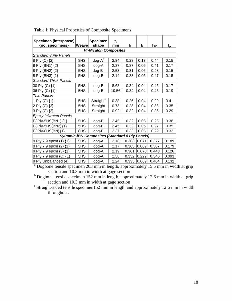
Table I: Physical Properties of Composite Specimens
Specimen (interphase) {no. specimens} Weave
Specimen shape
t,mm ff fi fSiC fp
Hi-Nicalon CompositesStandard 8 Ply Panels8 Ply (C) {2} 8HS dog-Aa 2.84 0.28 0.13 0.44 0.158 Ply (BN1) {2} 8HS dog-A 2.37 0.37 0.05 0.41 0.178 Ply (BN2) {2} 5HS dog-Bb 2.53 0.31 0.06 0.48 0.158 Ply (BN3) {1} 5HS dog-B 2.14 0.33 0.05 0.47 0.15Standard Thick Panels30 Ply (C) {1} 5HS dog-B 8.68 0.34 0.04 0.45 0.1736 Ply (C) {1} 5HS dog-B 10.56 0.34 0.04 0.43 0.19Thin Panels1 Ply (C) {1} 5HS Straights 0.38 0.26 0.04 0.29 0.412 Ply (C) {2} 5HS Straight 0.73 0.28 0.04 0.33 0.353 Ply (C) {2} 5HS Straight 0.92 0.32 0.04 0.35 0.29Epoxy Iniltrated PanelsE8Ply-5HS(BN1) {1} 5HS dog-B 2.45 0.32 0.05 0.25 0.38E8Ply-5HS(BN2) {1} 5HS dog-B 2.45 0.32 0.05 0.27 0.35E8Ply-8HS(BN) {1} 8HS dog-B 2.37 0.33 0.05 0.29 0.33
Sylramic-iBN Composites (Standard 8 Ply Panels)8 Ply 7.9 epcm (1) {1} 5HS dog-A 2.18 0.363 0.071 0.377 0.1898 Ply 7.9 epcm (2) {1} 5HS dog-A 2.17 0.365 0.069 0.387 0.1798 Ply 7.9 epcm (3) }1} 5HS dog-A 2.19 0.361 0.070 0.443 0.1268 Ply 7.9 epcm (C) {1} 5HS dog-A 2.38 0.332 0.229 0.346 0.0938 Ply Unbalanced {4} 5HS dog-A 2.24 0.335 0.069 0.464 0.132a Dogbone tensile specimen 203 mm in length, approximately 15.5 mm in width at grip
section and 10.3 mm in width at gage sectionb Dogbone tensile specimen 152 mm in length, approximately 12.6 mm in width at grip
section and 10.3 mm in width at gage sections Straight-sided tensile specimen152 mm in length and approximately 12.6 mm in width
throughout.
19
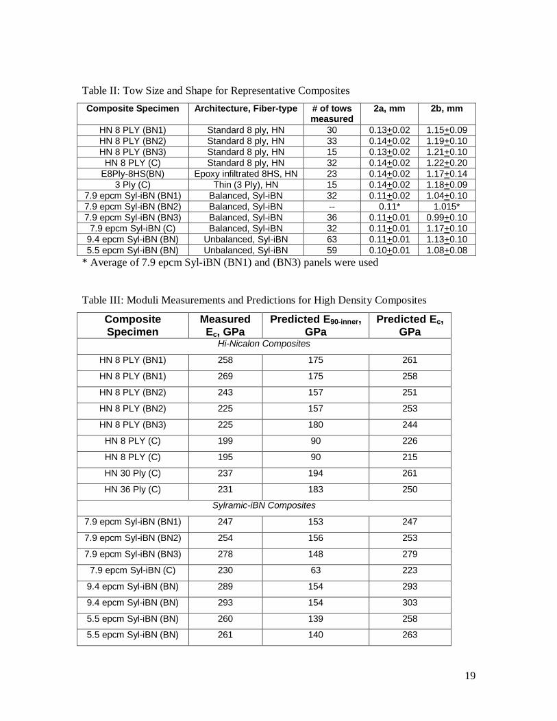
Table II: Tow Size and Shape for Representative Composites
Composite Specimen Architecture, Fiber-type # of tows measured
2a, mm 2b, mm
HN 8 PLY (BN1) Standard 8 ply, HN 30 0.13+0.02 1.15+0.09HN 8 PLY (BN2) Standard 8 ply, HN 33 0.14+0.02 1.19+0.10HN 8 PLY (BN3) Standard 8 ply, HN 15 0.13+0.02 1.21+0.10
HN 8 PLY (C) Standard 8 ply, HN 32 0.14+0.02 1.22+0.20E8Ply-8HS(BN) Epoxy infiltrated 8HS, HN 23 0.14+0.02 1.17+0.14
3 Ply (C) Thin (3 Ply), HN 15 0.14+0.02 1.18+0.097.9 epcm Syl-iBN (BN1) Balanced, Syl-iBN 32 0.11+0.02 1.04+0.107.9 epcm Syl-iBN (BN2) Balanced, Syl-iBN -- 0.11* 1.015*7.9 epcm Syl-iBN (BN3) Balanced, Syl-iBN 36 0.11+0.01 0.99+0.10
7.9 epcm Syl-iBN (C) Balanced, Syl-iBN 32 0.11+0.01 1.17+0.109.4 epcm Syl-iBN (BN) Unbalanced, Syl-iBN 63 0.11+0.01 1.13+0.105.5 epcm Syl-iBN (BN) Unbalanced, Syl-iBN 59 0.10+0.01 1.08+0.08
* Average of 7.9 epcm Syl-iBN (BN1) and (BN3) panels were used
Table III: Moduli Measurements and Predictions for High Density Composites
Composite Specimen
Measured Ec, GPa
Predicted E90-inner, GPa
Predicted Ec, GPa
Hi-Nicalon Composites
HN 8 PLY (BN1) 258 175 261
HN 8 PLY (BN1) 269 175 258
HN 8 PLY (BN2) 243 157 251
HN 8 PLY (BN2) 225 157 253
HN 8 PLY (BN3) 225 180 244
HN 8 PLY (C) 199 90 226
HN 8 PLY (C) 195 90 215
HN 30 Ply (C) 237 194 261
HN 36 Ply (C) 231 183 250
Sylramic-iBN Composites
7.9 epcm Syl-iBN (BN1) 247 153 247
7.9 epcm Syl-iBN (BN2) 254 156 253
7.9 epcm Syl-iBN (BN3) 278 148 279
7.9 epcm Syl-iBN (C) 230 63 223
9.4 epcm Syl-iBN (BN) 289 154 293
9.4 epcm Syl-iBN (BN) 293 154 303
5.5 epcm Syl-iBN (BN) 260 139 258
5.5 epcm Syl-iBN (BN) 261 140 263
20
(a) (b) (c)
Figure 1: Approaches to composite fabrication
Approaches to Composite Fabrication
CVI BN or C Infiltration
CVI SiC Infiltration
Dog BoneTensile Bars
Machined
Final CVI SiCInfiltration
Cut into Rectangular Shapes
Tensile Bars Machined
2D lay-up fixed in tooling
Interphase deposition, then removal from tool
C-fiber plySiC-fiber ply
Delamination
C-fiber plySiC-fiber ply
Delamination
CVI BN or C Infiltration
CVI SiC infiltration,removal from tool,and delamination
Straight-SidedTensile Bars
Machined8, 30, & 36 plyStandard Panels
8 plyEpoxy-Infiltrated
1, 2, and 3 plyDelaminated Panels
GE Power Systems Composites, Newark DE
Epoxy Infiltrate
(green) (white)
21
(a) HN 1 Ply Longitudinal Section
(b) HN 3 Ply Longitudinal Section
(c) HN 8 Ply (BN1) Cross-Section
(d) HN 30 Ply Longitudinal Section
(e) HN E8Ply-8HS(BN) Longitudinal Section
22
(f) Syl-iBN balanced 7.9 epcm
(g) Syl-iBN longitudinal (9.4 epcm) unbalanced
(h) Syl-iBN longitudinal (5.5 epcm) unbalanced
(i) Syl-iBN balanced 7.9 epcm with carbon interphase
Figure 2: Microstructures of selected CVI SiC matrix composites. All of the specimens
have a BN interphase except for (i).
23
0
100
200
300
400
500
600
0 0.1 0.2 0.3 0.4 0.5 0.6
Strain, %
Str
ess,
MP
a
CVI5.5 epcm
fo=0.12 (002)E = 261 GPa
CVI; 9.4epcm8 ply (002)fo=0.21E=293 GPa
CVI7.9epcmfo=0.18
E=271 GPa
E = 253 GPa
C-interphase fo = 0.17
E = 230 GPa
0
50
100
150
200
250
300
350
400
450
500
0 0.2 0.4 0.6 0.8 1
Strain, %
Str
ess,
MP
a
30 Ply; E = 221 GPafo = 0.17; 8.6 mm thick
36 Ply; E = 217 GPafo = 0.17; 10.5mm thick
8 Ply (BN3); E = 225 GPafo = 0.18; 2.35 mm thick
8 Ply (C); E = 177 GPafo = 0.14; 2.88 mm thick
fo refers to the volume fraction of fiber in the
loading direction
2 Ply; E = 102 GPafo = 0.14; 0.76 mm thick
3Ply; E = 114 GPafo = 0.16; 0.92 mm thick
8 Ply (BN2); E = 244 GPafo = 0.16; 2.5 mm thick8 Ply (BN1); E = 258 GPa
fo = 0.17; 2.5 mm thick
E8Ply-8HS; E = 118 GPafo = 0.17; 2.37 mm thick
E8Ply-5HS; E = 108 GPafo = 0.16; 2.45 mm thick
(a)
(b)
Figure 3: Tensile stress-strain behavior of (a) HN CVI SiC and (b) Syl-iBN CVI SiC
composites.
24
0
50
100
150
200
250
300
350
1.5 1.7 1.9 2.1 2.3 2.5 2.7 2.9Density, g/cc
E, G
Pa
HN 8 Ply
HNEpoxy-Infiltrated
HN Thin Panels
HN Thick Panels
Syl-iBN balanced
Syl-iBN unbalanced
Figure 4: Effect of various physical properties on elastic modulus.
25
0
2000
4000
6000
8000
10000
12000
14000
0 2000 4000 6000 8000 10000 12000 14000
(E/ρ )1/2, m/s
Ce,
m/s
Nb
NiAl
GN-10Si3N4
CVD SiC
epoxy infiltrated
thin panels
HN Std 8 ply
thick panels
SYL-iBN Std 8 ply
Figure 5: Measured speed of sound versus measured (E/)1/2.
26
(a) (b)
Figure 6: Schematic representation (a) of 0o and 90o minicomposite construction and (b) a
typical 90o minicomposite from HN 8PLY (BN3).
CVI SiC“shell”
Mixture of fibers,
interphase, CVI SiC, and
inner-tow porosity
22aa
22bb
27
-50
0
50
100
150
200
250
300
350
1.5 1.7 1.9 2.1 2.3 2.5 2.7 2.9
Density, g/cc
"Bac
ked
ou
t" E
(90
), G
Pa
HN Std 8 Ply
HN Epoxy-Infiltrated
HN Thick Panels
HN Thin Panels
Little or no load carried by 90 o Minicomposites
Significant load carried by 90 o Minicomposites
Syl-iBNbalanced
Syl-iBNunbalanced
C-interphase
Figure 7: Effective elastic modulus of the 90o minicomposites.
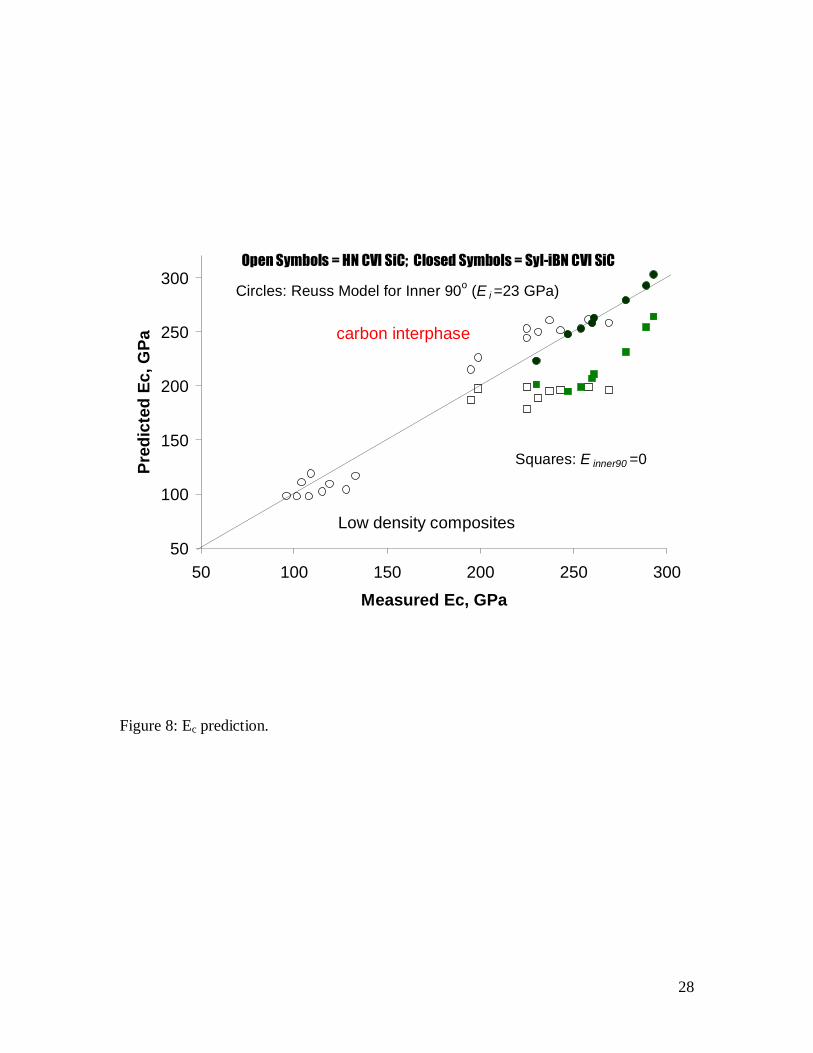
28
50
100
150
200
250
300
50 100 150 200 250 300
Measured Ec, GPa
Pre
dic
ted
Ec,
GP
a
Circles: Reuss Model for Inner 90o (E i =23 GPa)
Squares: E inner90 =0
carbon interphase
Open Symbols = HN CVI SiC; Closed Symbols = Syl-iBN CVI SiC
Low density composites
Figure 8: Ec prediction.
Related Documents