ing the blanket module: Multiphysical computations and rapid turnaround capabilities anth Munipalli, C.M.Rowell, K.-Y. Szema, P.-Y.Huang Comp Inc., 2629 Townsgate Rd., #105, Westlake Village, CA 91361 Ying, Neil Morley, Mohamed Abdou, Sergey Smolentsev, Manmeet Narul Meeting, UCLA, August 14, 2008 CAD Multiphysics Sim ulation M anagem ent V ir Tual B lanket M odule CAD Multiphysics Sim ulation M anagem ent V ir Tual B lanket M odule

Modeling the blanket module: Multiphysical computations and rapid turnaround capabilities Ramakanth Munipalli, C.M.Rowell, K.-Y. Szema, P.-Y.Huang HyPerComp.
Dec 28, 2015
Welcome message from author
This document is posted to help you gain knowledge. Please leave a comment to let me know what you think about it! Share it to your friends and learn new things together.
Transcript
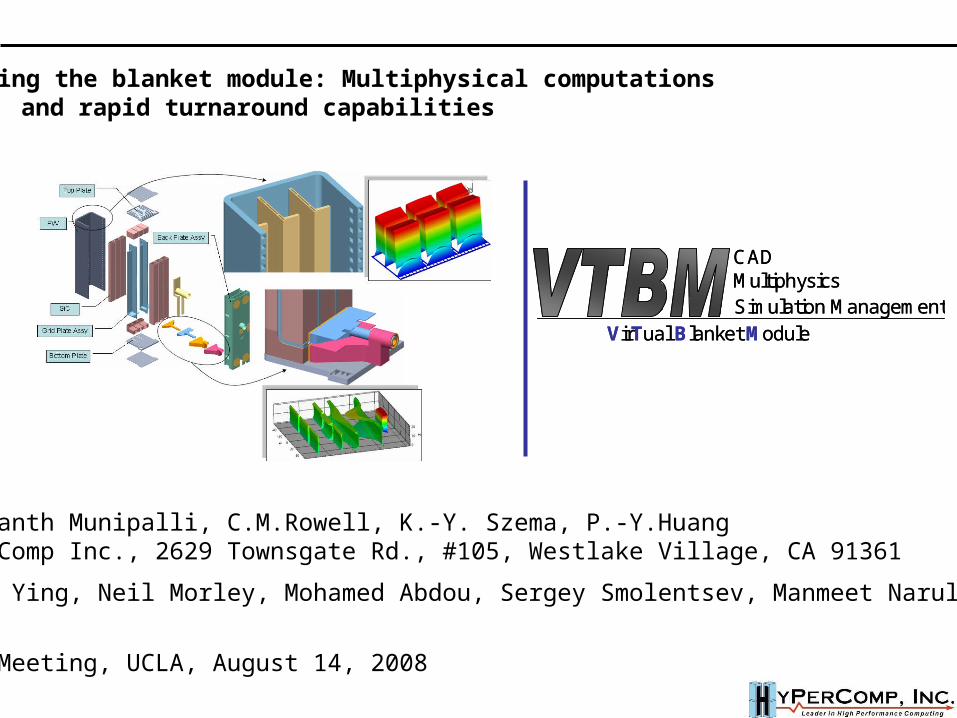
Modeling the blanket module: Multiphysical computations and rapid turnaround capabilities
Ramakanth Munipalli, C.M.Rowell, K.-Y. Szema, P.-Y.HuangHyPerComp Inc., 2629 Townsgate Rd., #105, Westlake Village, CA 91361
Alice Ying, Neil Morley, Mohamed Abdou, Sergey Smolentsev, Manmeet NarulaUCLA
FNST Meeting, UCLA, August 14, 2008
CADMultiphysicsSimulation Management
VirTual Blanket Module
CADMultiphysicsSimulation Management
VirTual Blanket Module
Objective:
To create a simulation management software with integrated prediction capability for blanket modules (extendable to the divertor and other PFCs) operating in a fusion environment
Phase-I SBIR: CAD-Centric Management System for a virtual blanket module
Period of performance: July 2008 – March 2009
• Conventional modeling involves using various codes to individually model physics
• This is a CAD-centric multiphysical software integration project – no new physical modeling ability is sought in individual disciplines
Outline
Scope of the VTBM project
A description of the functionality and uniqueness of the VTBM environment
Some details on implementation
Phase-I tasks
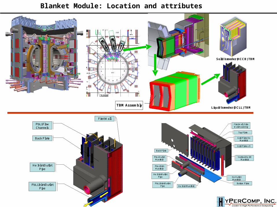
TBM Assembly
Solid breeder (HCCB) TBM
Liquid breeder (DCLL) TBM
First Wall, Side Wall Assembly
Top Plate
Bottom PlatePbLi Inlet/Outlet Pipe
He Inlet/Outlet Pipe
Back Plate
PbLi Inlet Manifold
PbLi Outlet Manifold
Grid Plate x 9
Grid Plate He Manifold
Vertical He I/O Manifold
He Inlet Manifold
He Outlet Manifold
First Wall
PbLi Inlet/Outlet Pipe
PbLi Flow Channels
Back Plate
He Inlet/Outlet Pipe
Blanket Module: Location and attributes
FW
Top Plate
SiC
Grid Plate Assy
Bottom Plate
Back Plate Assy
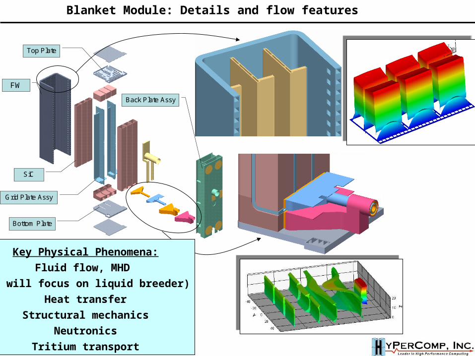
Blanket Module: Details and flow features
Key Physical Phenomena:
Fluid flow, MHD
(we will focus on liquid breeder)
Heat transfer
Structural mechanics
Neutronics
Tritium transport
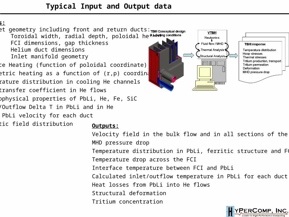
Inputs:Blanket geometry including front and return ducts:
Toroidal width, radial depth, poloidal height,FCI dimensions, gap thicknessHelium duct dimensionsInlet manifold geometry
Surface Heating (function of poloidal coordinate)
Volumetric heating as a function of (r,p) coordinates
Temperature distribution in cooling He channels
Heat transfer coefficient in He flows
Thermophysical properties of PbLi, He, Fe, SiC
Inlet/Outflow Delta T in PbLi and in He
Inlet PbLi velocity for each duct
Magnetic field distribution Outputs:
Velocity field in the bulk flow and in all sections of the gap
MHD pressure drop
Temperature distribution in PbLi, ferritic structure and FCI
Temperature drop across the FCI
Interface temperature between FCI and PbLi
Calculated inlet/outflow temperature in PbLi for each duct
Heat losses from PbLi into He flows
Structural deformation
Tritium concentration
Typical Input and Output data
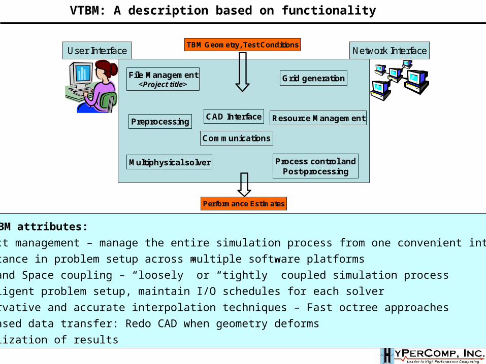
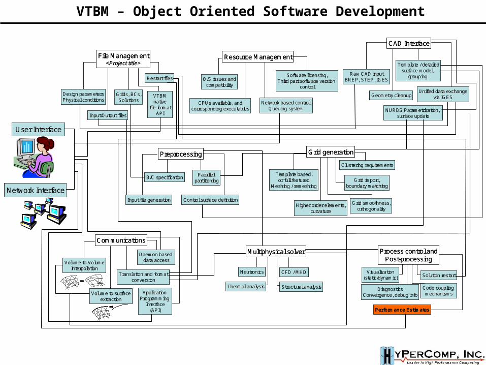
File Management<Project title>
CAD Interface
Grid generation
Communications
Resource Management
Multiphysical solver
Preprocessing
Process control andPost-processing
Performance Estimates
TBM Geometry, Test ConditionsUser Interface Network Interface
VTBM: A description based on functionality
Major VTBM attributes: Project management – manage the entire simulation process from one convenient interface Assistance in problem setup across multiple software platforms Time and Space coupling – “loosely” or “tightly” coupled simulation process Intelligent problem setup, maintain I/O schedules for each solver Conservative and accurate interpolation techniques – Fast octree approaches CAD-based data transfer: Redo CAD when geometry deforms Visualization of results
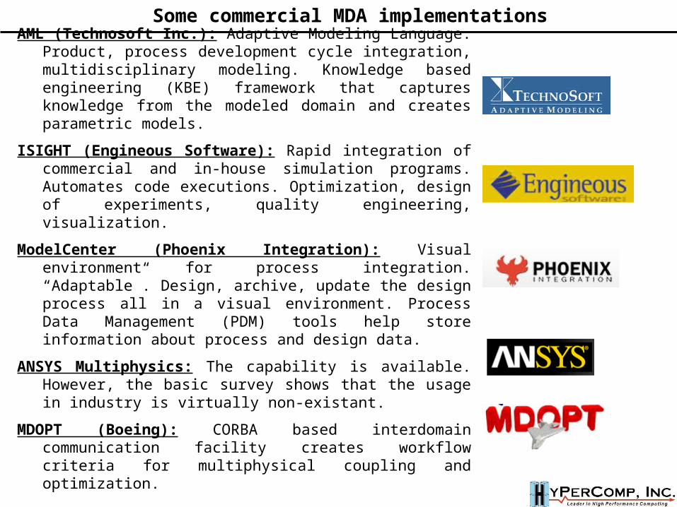
AML (Technosoft Inc.): Adaptive Modeling Language. Product, process development cycle integration, multidisciplinary modeling. Knowledge based engineering (KBE) framework that captures knowledge from the modeled domain and creates parametric models.
ISIGHT (Engineous Software): Rapid integration of commercial and in-house simulation programs. Automates code executions. Optimization, design of experiments, quality engineering, visualization.
ModelCenter (Phoenix Integration): Visual environment for process integration. “Adaptable”. Design, archive, update the design process all in a visual environment. Process Data Management (PDM) tools help store information about process and design data.
ANSYS Multiphysics: The capability is available. However, the basic survey shows that the usage in industry is virtually non-existant.
MDOPT (Boeing): CORBA based interdomain communication facility creates workflow criteria for multiphysical coupling and optimization.
Some commercial MDA implementations
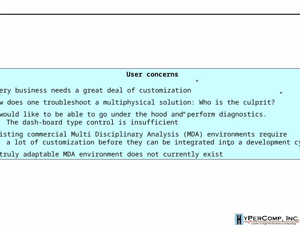
User concerns
“Every business needs a great deal of customization”
“How does one troubleshoot a multiphysical solution: Who is the culprit?”
“I would like to be able to go under the hood and perform diagnostics. The dash-board type control is insufficient”
“Existing commercial Multi Disciplinary Analysis (MDA) environments require a lot of customization before they can be integrated into a development cycle”
“A truly adaptable MDA environment does not currently exist”
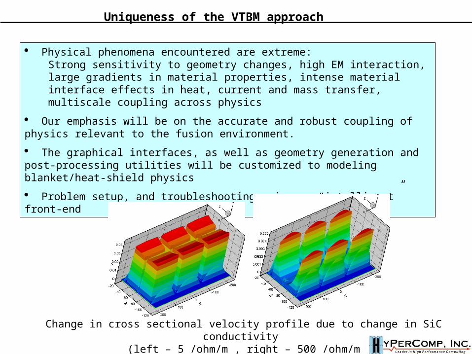
Physical phenomena encountered are extreme:Strong sensitivity to geometry changes, high EM interaction, large gradients in material properties, intense material interface effects in heat, current and mass transfer, multiscale coupling across physics
Our emphasis will be on the accurate and robust coupling of physics relevant to the fusion environment.
The graphical interfaces, as well as geometry generation and post-processing utilities will be customized to modeling blanket/heat-shield physics
Problem setup, and troubleshooting using an “intelligent” front-end
Change in cross sectional velocity profile due to change in SiC conductivity (left – 5 /ohm/m , right – 500 /ohm/m
Uniqueness of the VTBM approach
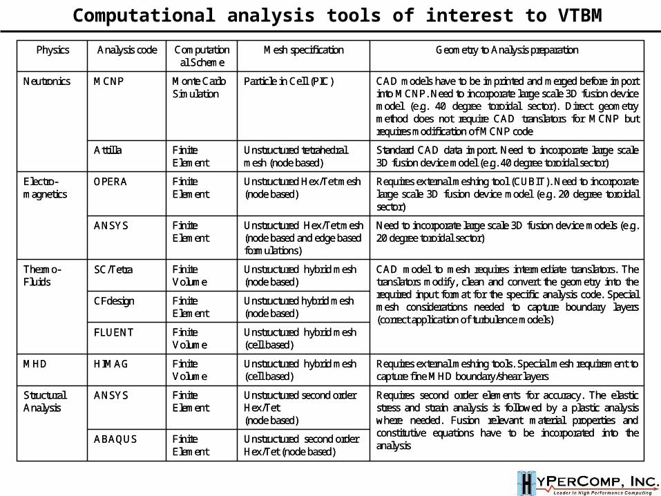
Unstructured second order Hex/Tet (node based)
Finite Element
ABAQUS
Requires second order elements for accuracy. The elastic stress and strain analysis is followed by a plastic analysis where needed. Fusion relevant material properties and constitutive equations have to be incorporated into the analysis
Unstructured second order Hex/Tet(node based)
Finite Element
ANSYSStructural Analysis
Requires external meshing tools. Special mesh requirement to capture fine MHD boundary/shear layers
Unstructured hybrid mesh(cell based)
Finite Volume
HIMAGMHD
Unstructured hybrid mesh(cell based)
Finite Volume
FLUENT
Unstructured hybrid mesh (node based)
Finite Element
CFdesign
CAD model to mesh requires intermediate translators. The translators modify, clean and convert the geometry into the required input format for the specific analysis code. Special mesh considerations needed to capture boundary layers (correct application of turbulence models)
Unstructured hybrid mesh (node based)
Finite Volume
SC/TetraThermo-Fluids
Need to incorporate large scale 3D fusion device models (e.g. 20 degree toroidal sector)
Unstructured Hex/Tet mesh(node based and edge based formulations)
Finite Element
ANSYS
Requires external meshing tool (CUBIT). Need to incorporate large scale 3D fusion device model (e.g. 20 degree toroidalsector)
Unstructured Hex/Tet mesh(node based)
Finite Element
OPERAElectro-magnetics
Standard CAD data import. Need to incorporate large scale 3D fusion device model (e.g. 40 degree toroidal sector)
Unstructured tetrahedral mesh (node based)
Finite Element
Attilla
CAD models have to be imprinted and merged before import into MCNP. Need to incorporate large scale 3D fusion device model (e.g. 40 degree toroidal sector). Direct geometry method does not require CAD translators for MCNP but requires modification of MCNP code
Particle in Cell (PIC)Monte Carlo Simulation
MCNPNeutronics
Geometry to Analysis preparationMesh specificationComputational Scheme
Analysis codePhysics
Computational analysis tools of interest to VTBM
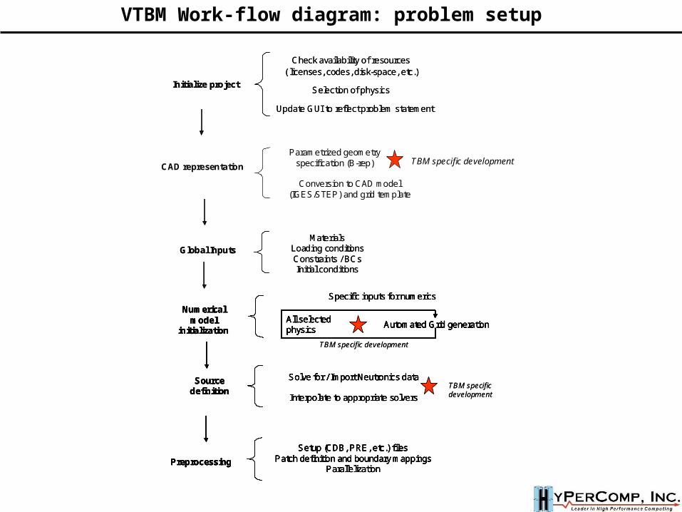
Check availability of resources ( licenses, codes, disk-space, etc.)
Initialize projectSelection of physics
Update GUI to reflect problem statement
Check availability of resources ( licenses, codes, disk-space, etc.)
Initialize projectSelection of physics
Update GUI to reflect problem statement
MaterialsLoading conditionsConstraints / BCsInitial conditions
Global InputsMaterials
Loading conditionsConstraints / BCsInitial conditions
Global Inputs
Parametrized geometry specification (B-rep)
Conversion to CAD model (IGES/STEP) and grid template
CAD representationTBM specific development
Specific inputs for numerics
Automated Grid generationAll selected physics
Numerical model
initialization
Solve for / Import Neutronics data
Interpolate to appropriate solvers
Source definition
Setup (CDB, PRE, etc.) filesPatch definition and boundary mappings
Parallelization Preprocessing
TBM specific development
TBM specific development
Specific inputs for numerics
Automated Grid generationAll selected physics
Numerical model
initialization
Solve for / Import Neutronics data
Interpolate to appropriate solvers
Source definition
Setup (CDB, PRE, etc.) filesPatch definition and boundary mappings
Parallelization Preprocessing
Specific inputs for numerics
Automated Grid generationAll selected physics
Numerical model
initialization
Specific inputs for numerics
Automated Grid generationAll selected physics
Automated Grid generationAll selected physics
Numerical model
initialization
Solve for / Import Neutronics data
Interpolate to appropriate solvers
Source definition
Solve for / Import Neutronics data
Interpolate to appropriate solvers
Source definition
Setup (CDB, PRE, etc.) filesPatch definition and boundary mappings
Parallelization Preprocessing
Setup (CDB, PRE, etc.) filesPatch definition and boundary mappings
Parallelization Preprocessing
TBM specific development
TBM specific development
VTBM Work-flow diagram: problem setup
Dynamics data visualization(adapted tecplot, etc.)
Coupling mechanisms
Post processing
TBM specific development
Dynamics data visualization(adapted tecplot, etc.)
Coupling mechanisms
Post processing
Dynamics data visualization(adapted tecplot, etc.)
Coupling mechanisms
Post processing
TBM specific development
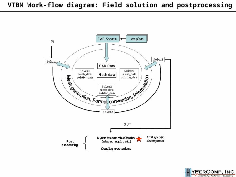
CAD Data
Mesh data
CAD Data
Mesh dataSolver-1
mesh_datasolution_data
Solver-2mesh_data
solution_data
TemplateTemplateCAD SystemCAD System TemplateTemplateCAD SystemCAD System
Solver-3mesh_data
solution_data
Solver-1Solver-3
Solver-2
IN
OUT
VTBM Work-flow diagram: Field solution and postprocessing
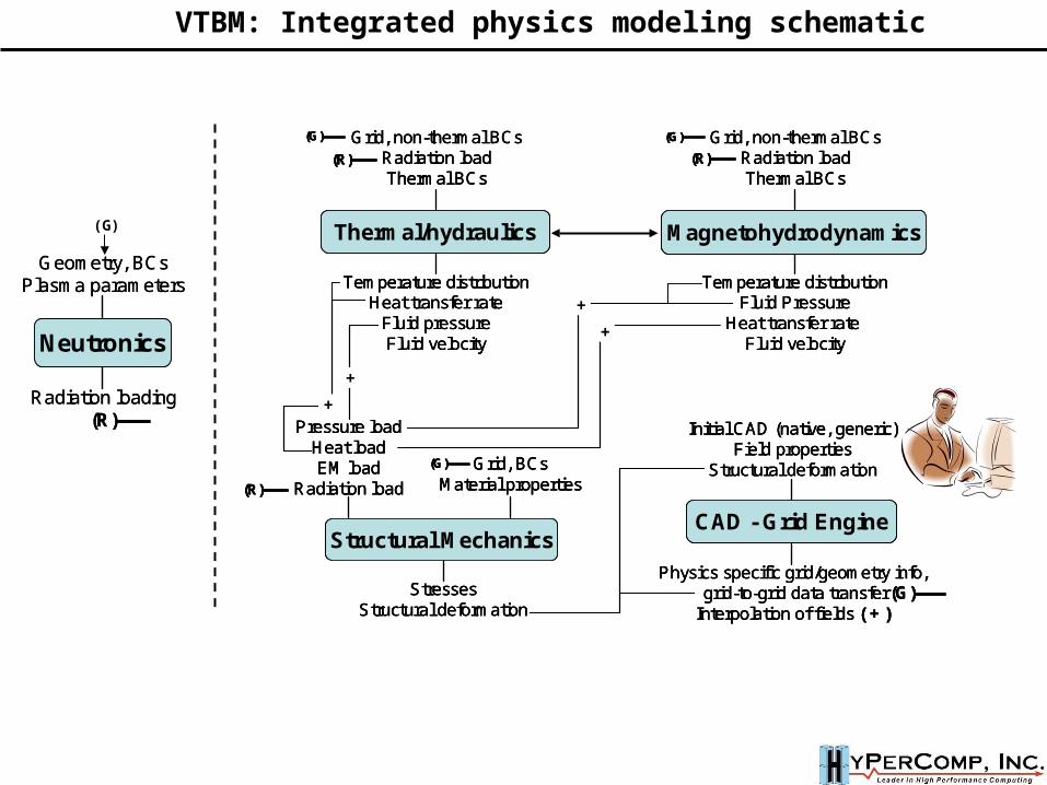
Pressure loadHeat loadEM load
Radiation load
StressesStructural deformation
Structural Mechanics
Grid, BCsMaterial properties
Grid, non-thermal BCsRadiation loadThermal BCs
Temperature distributionHeat transfer rate
Fluid pressureFluid velocity
Thermal/hydraulics
Grid, non-thermal BCsRadiation loadThermal BCs
Temperature distributionFluid Pressure
Heat transfer rate Fluid velocity
Magnetohydrodynamics
Initial CAD (native, generic)Field properties
Structural deformation
Physics specific grid/geometry info,grid-to-grid data transfer
Interpolation of fields ( + )
CAD - Grid Engine
(R)(R)
(R)(R) (R)(R)
(G)
(G)(G)
(G)(G)
(G)(G)
+
+
+
+
Pressure loadHeat loadEM load
Radiation load
StressesStructural deformation
Structural Mechanics
Grid, BCsMaterial properties
Pressure loadHeat loadEM load
Radiation load
StressesStructural deformation
Structural Mechanics
Grid, BCsMaterial properties
Grid, non-thermal BCsRadiation loadThermal BCs
Temperature distributionHeat transfer rate
Fluid pressureFluid velocity
Thermal/hydraulics
Grid, non-thermal BCsRadiation loadThermal BCs
Temperature distributionHeat transfer rate
Fluid pressureFluid velocity
Thermal/hydraulics
Grid, non-thermal BCsRadiation loadThermal BCs
Temperature distributionFluid Pressure
Heat transfer rate Fluid velocity
Magnetohydrodynamics
Grid, non-thermal BCsRadiation loadThermal BCs
Temperature distributionFluid Pressure
Heat transfer rate Fluid velocity
Magnetohydrodynamics
Initial CAD (native, generic)Field properties
Structural deformation
Physics specific grid/geometry info,grid-to-grid data transfer
Interpolation of fields ( + )
CAD - Grid Engine
Initial CAD (native, generic)Field properties
Structural deformation
Physics specific grid/geometry info,grid-to-grid data transfer
Interpolation of fields ( + )
CAD - Grid Engine
(R)(R)
(R)(R) (R)(R)
(G)(G)
(G)(G)
(G)(G)
(G)(G)
+
+
+
+
Geometry, BCsPlasma parameters
Radiation loading(R)
Neutronics
Geometry, BCsPlasma parameters
Radiation loading(R)
Neutronics
VTBM: Integrated physics modeling schematic
(G)
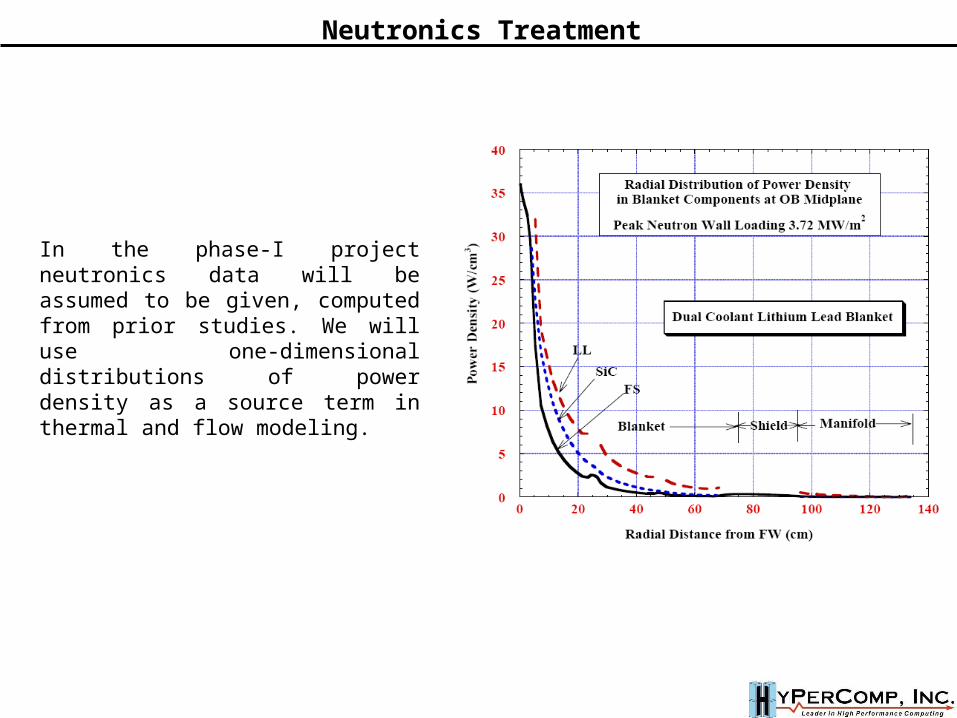
Neutronics Treatment
In the phase-I project neutronics data will be assumed to be given, computed from prior studies. We will use one-dimensional distributions of power density as a source term in thermal and flow modeling.
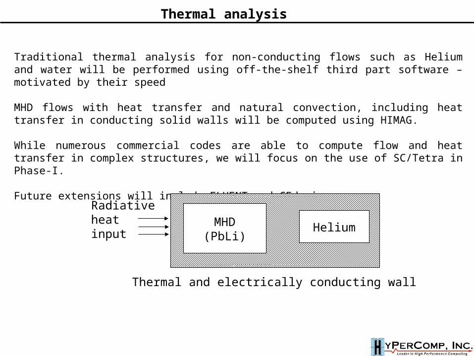
Thermal analysis
Traditional thermal analysis for non-conducting flows such as Helium and water will be performed using off-the-shelf third part software – motivated by their speed
MHD flows with heat transfer and natural convection, including heat transfer in conducting solid walls will be computed using HIMAG.
While numerous commercial codes are able to compute flow and heat transfer in complex structures, we will focus on the use of SC/Tetra in Phase-I.
Future extensions will include FLUENT and CFdesign.
MHD(PbLi)
Helium
Thermal and electrically conducting wall
Radiative heat input

1 / Ha
1 / sqrt(Ha)
U(z)
j(y,z)
Ha≈Ha-1
B
//≈Ha-1/2
2h
Hartmann layerSide layer
B
Side layersHa
1~
Hartmann layersHa
1~
BBB
Side layersHa
1~Side layers
Ha
1~
Hartmann layersHa
1~Hartmann layersHa
1~
FLOW
The exacting needs of numerical MHD
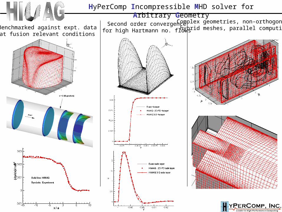
Second order convergencefor high Hartmann no. flowsBenchmarked against expt. data
at fusion relevant conditions
Complex geometries, non-orthogonal,hybrid meshes, parallel computing
HyPerComp Incompressible MHD solver for Arbitrary Geometry
Task-PaneChangesOn Demand
Task-PaneChangesOn Demand
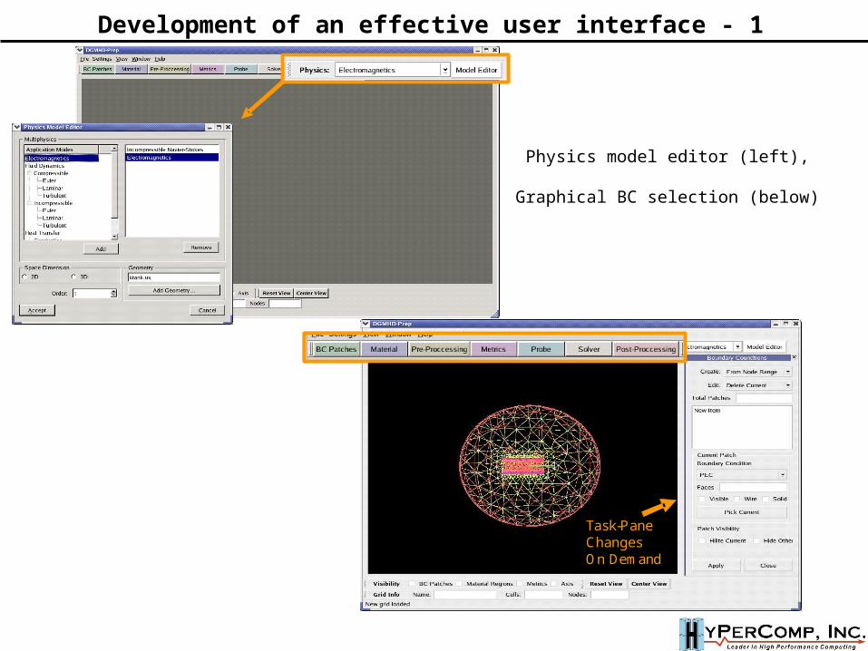
Development of an effective user interface - 1
Physics model editor (left),
Graphical BC selection (below)
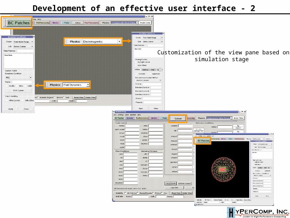
Development of an effective user interface - 2
Customization of the view pane based onsimulation stage
CGNSLibraryVersion_t(CGNS version number)
Axisymmetry_t BaseIterativeData_t(number o f steps)
Da taClass_t(data class)
Descriptor_t(text)
DimensionalUnit_t(base units)
Fam ily_t(fam ily nam e)
FlowEquationSet_t ConvergenceHistory_t(number o f ite rations)
Grav ity_t In tegralData_t ReferenceState_t Ro tatingCoord inates_t
Simu lationType_t(simula tion type)
UserDefinedData_t Zone_t(ve rtex and cell sizes)
CGNSB ase_t(physical and cell dim s)
root node
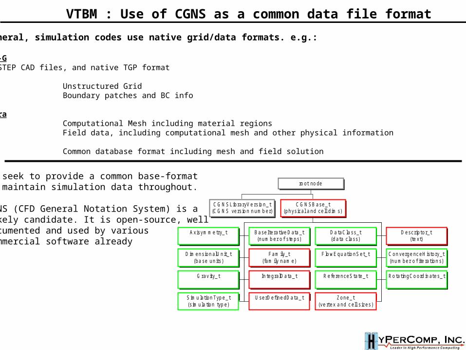
VTBM : Use of CGNS as a common data file format
We seek to provide a common base-formatto maintain simulation data throughout.
CGNS (CFD General Notation System) is a likely candidate. It is open-source, welldocumented and used by various commercial software already
In general, simulation codes use native grid/data formats. e.g.:
TEMPUS-GIGES, STEP CAD files, and native TGP formatHIMAGUX Unstructured GridUGM Boundary patches and BC info
SC/TetraPRE Computational Mesh including material regionsFLD Field data, including computational mesh and other physical informationANSYSCDB Common database format including mesh and field solution
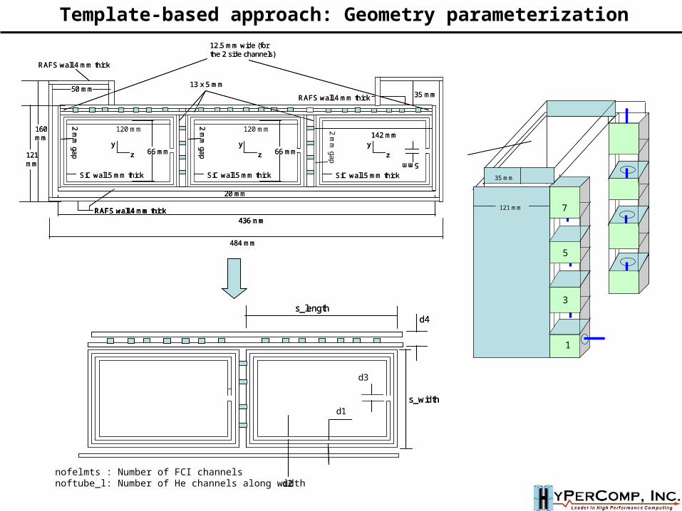
nofelmts : Number of FCI channelsnoftube_l: Number of He channels along width
s_length
d1
d2
d3
d4
s_width
s_length
d1
d2
d3
d4
s_width
RAFS wall 4 mm thick
SiC wall 5 mm thick
20 mm
z
y
2 mm
gap 5 mm
120 mm
SiC wall 5 mm thick
z
y
2 mm
gap 66 mm
120 mm
436 mmRAFS wall 4 mm thick
SiC wall 5 mm thick
142 mm
z
y
2 mm
gap 66 mm
484 mm
RAFS wall 4 mm thick
50 mm13 x 5 mm
12.5 mm wide (for the 2 side channels)
160 mm
35 mm
121 mm
RAFS wall 4 mm thick
SiC wall 5 mm thickSiC wall 5 mm thick
20 mm
z
y
2 mm
gap 5 mm 5 mm
120 mm
SiC wall 5 mm thickSiC wall 5 mm thick
z
y
2 mm
gap2 m
m gap 66 mm66 mm
120 mm
436 mmRAFS wall 4 mm thick
436 mmRAFS wall 4 mm thickRAFS wall 4 mm thick
SiC wall 5 mm thickSiC wall 5 mm thick
142 mm142 mm
z
y
2 mm
gap2 m
m gap 66 mm66 mm
484 mm
RAFS wall 4 mm thick
50 mm13 x 5 mm
12.5 mm wide (for the 2 side channels)
160 mm
35 mm
121 mm
5
3
1
7121 mm
35 mm
5
3
1
7121 mm
35 mm
Template-based approach: Geometry parameterization
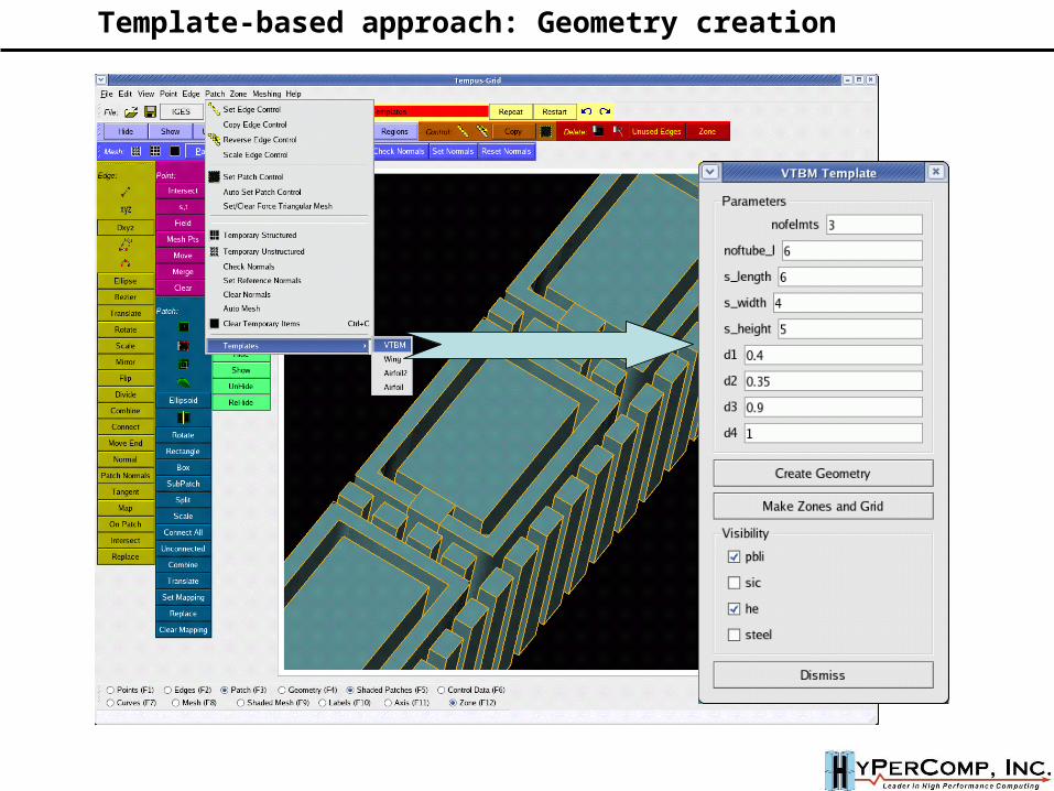
Template-based approach: Geometry creation
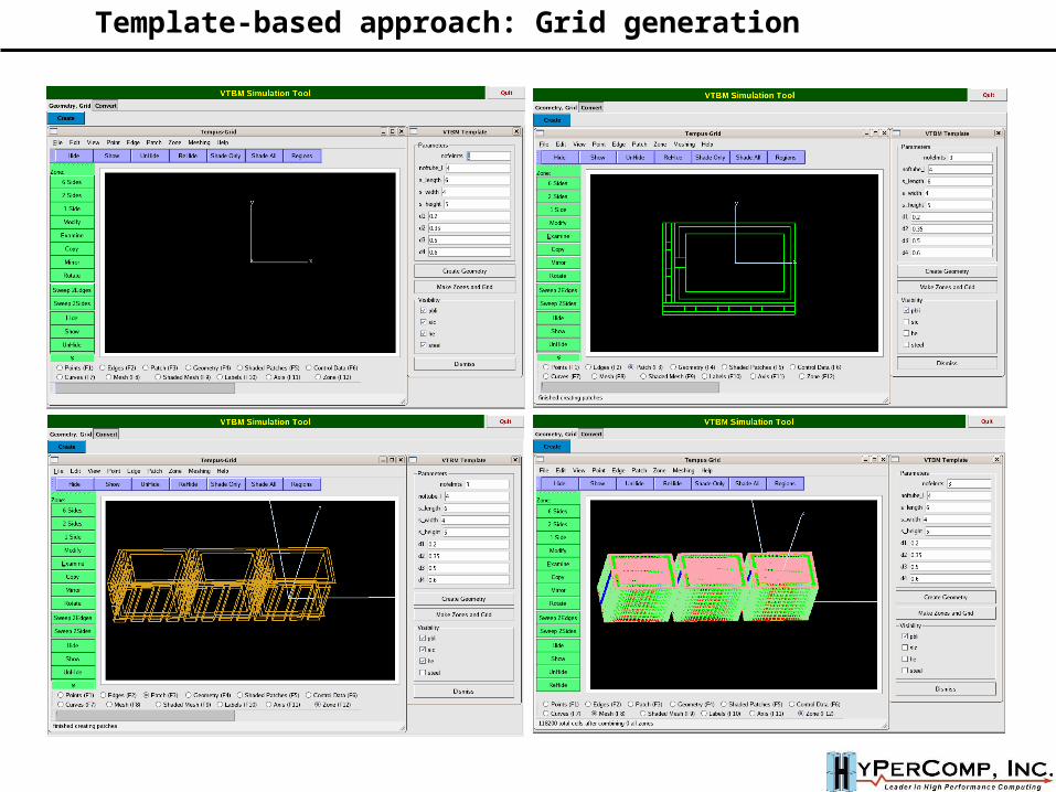
Template-based approach: Grid generation
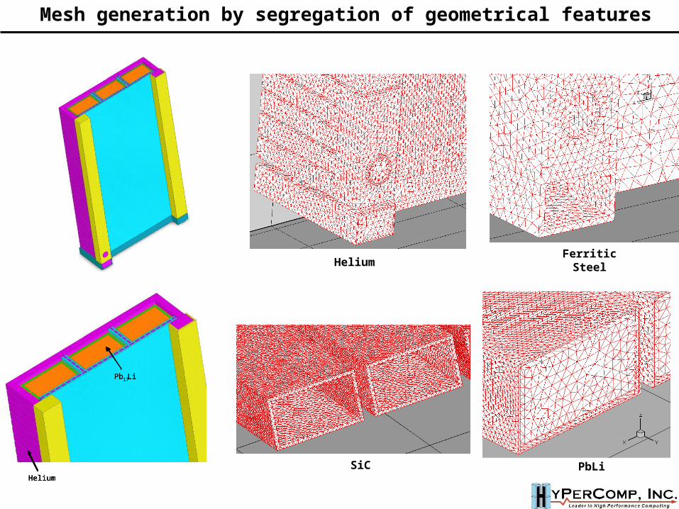
HeliumFerritic Steel
SiC PbLi
Pb17Li
Helium
Pb17LiPb17Li
HeliumHelium
Mesh generation by segregation of geometrical features
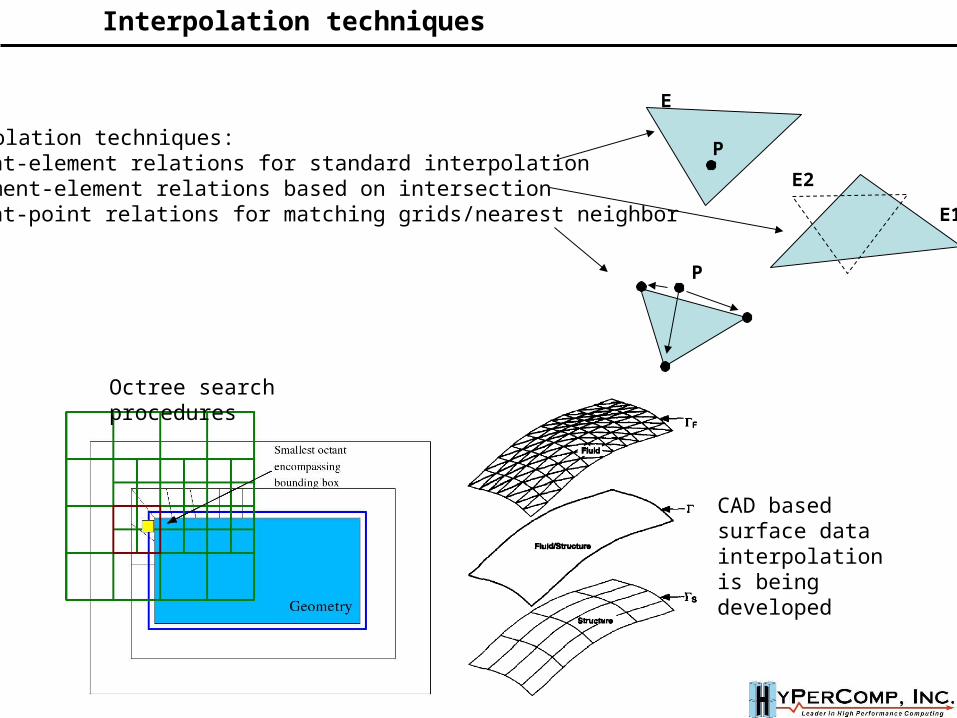
Interpolation techniques:Point-element relations for standard interpolationElement-element relations based on intersectionPoint-point relations for matching grids/nearest neighbor
E
P
E1
E2
P
Interpolation techniques
Octree search procedures
CAD based surface data interpolationis being developed
P1 P2
P3
P4
P5P6
P7
P8
P1 P2
P3
P4
P5P6
P7
P8Unified
CAD-Based Coupling
P1 P2
P3
P4
P5P6
P7
P8
P1 P2
P3
P4
P5P6
P7
P8
P1 P2
P3
P4
P5P6
P7
P8Unified
CAD-Based Coupling
P1 P2
P3
P4
P5P6
P7
P8Unified
CAD-Based Coupling
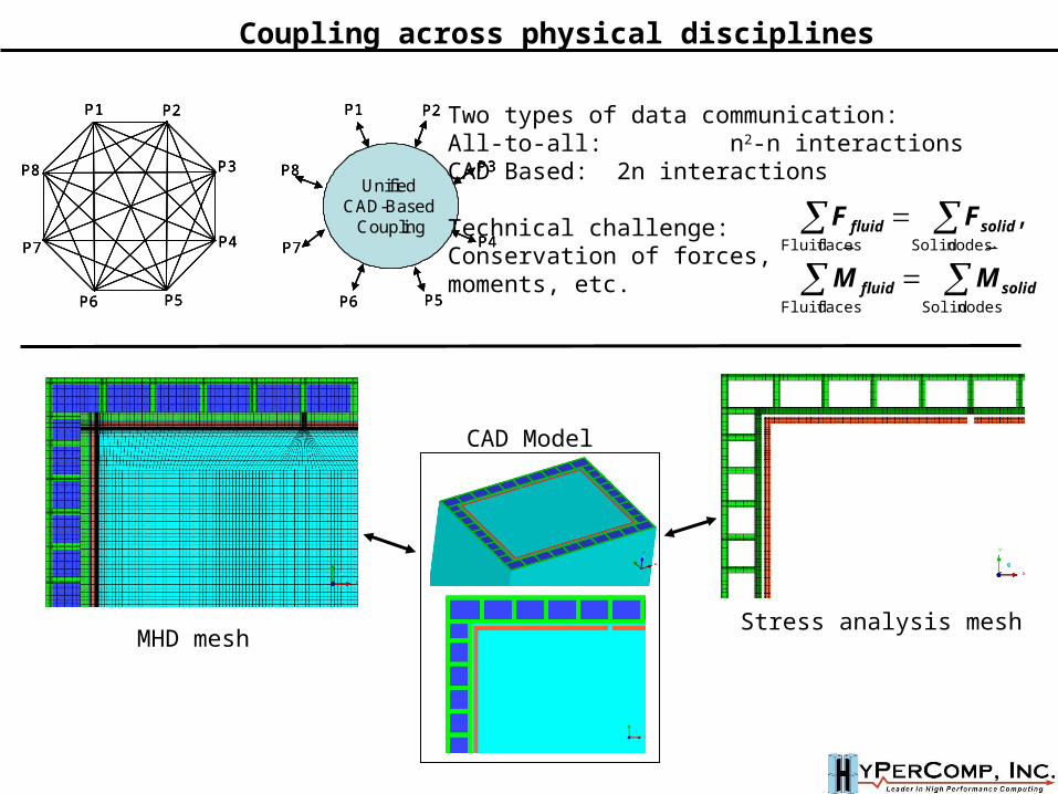
MHD mesh Stress analysis mesh
CAD Model
Two types of data communication:All-to-all: n2-n interactionsCAD Based: 2n interactions
Technical challenge:Conservation of forces, moments, etc.
nodes Solidfaces Fluid
nodes Solidfaces Fluid
,
solidfluid
solidfluid
MM
FF
Coupling across physical disciplines
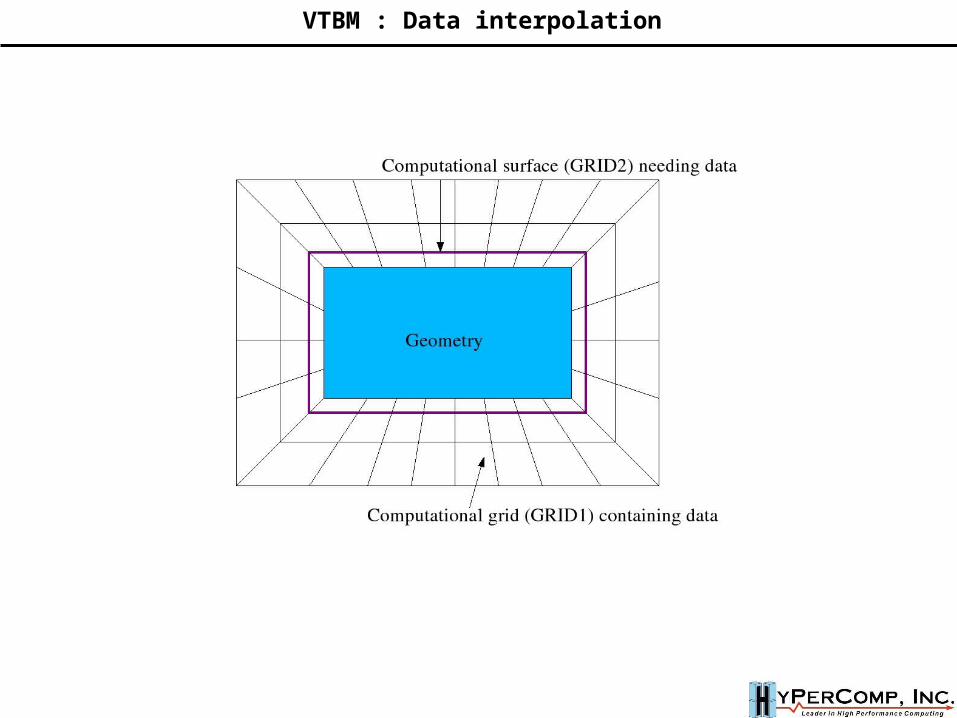
VTBM : Data interpolation
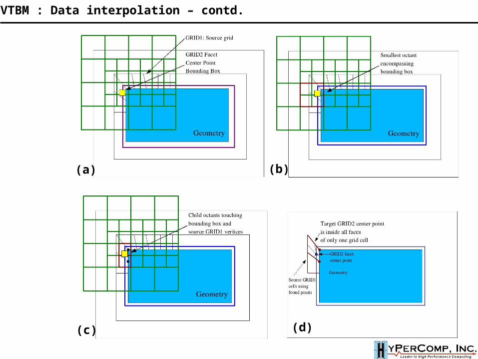
(a) (b)
(c) (d)
VTBM : Data interpolation – contd.
I
i
J
jjqipij
I
i
J
jijjqipij
vBuBW
PvBuBW
vuR)()(
)()(
),(
PCvuR ),(
1
1FCCCF TT
C
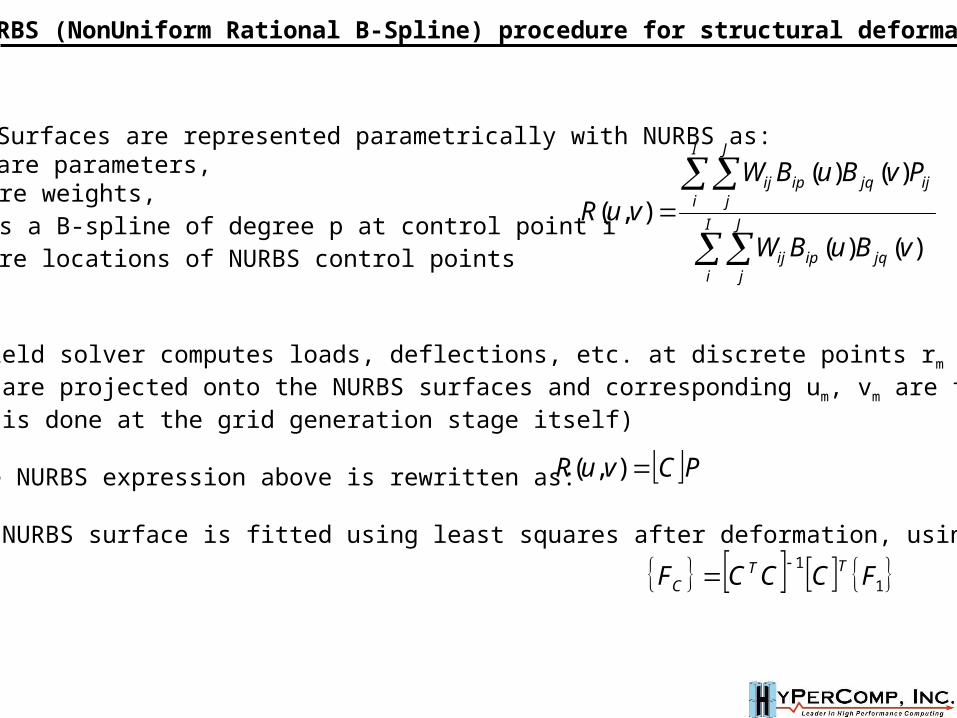
NURBS (NonUniform Rational B-Spline) procedure for structural deformation
CAD Surfaces are represented parametrically with NURBS as:u,v are parameters, Wij are weights, Bip is a B-spline of degree p at control point iPij are locations of NURBS control points
The field solver computes loads, deflections, etc. at discrete points rm
These are projected onto the NURBS surfaces and corresponding um, vm are found(This is done at the grid generation stage itself)
If the NURBS expression above is rewritten as:
A new NURBS surface is fitted using least squares after deformation, using:
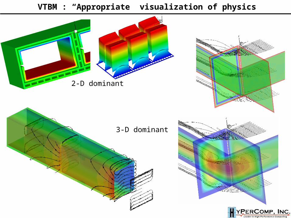
VTBM : “Appropriate” visualization of physics
2-D dominant
3-D dominant
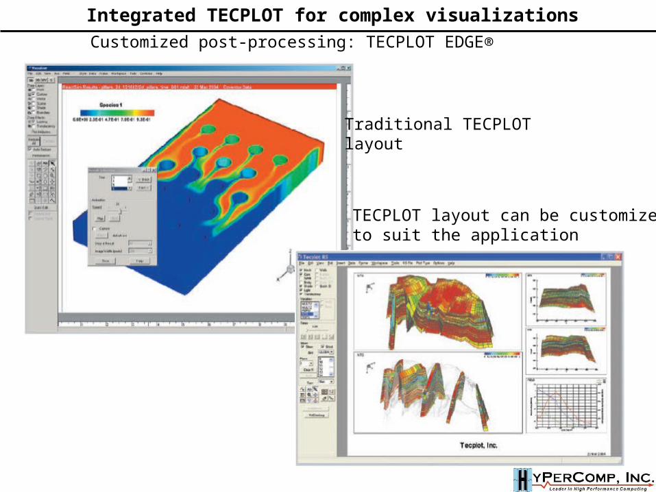
Customized post-processing: TECPLOT EDGE®
Traditional TECPLOTlayout
TECPLOT layout can be customized to suit the application
Integrated TECPLOT for complex visualizations
Dealing with third party software and APIs
Communication issues, resource management
Compliance with industry standards for I/O data
Interaction with the TBM community and timeline for development
Licensing, Documentation and Software dissemination
Using open source modules: CGM (Sandia, Argonne), CGNS (NASA)
VTBM – Software Development Issues
Preprocessing
B/C specification
Input file generation
Parallel partitioning
Control surface definition
Preprocessing
B/C specification
Input file generation
Parallel partitioning
Control surface definition
Multiphysical solver
Neutronics
Thermal analysis
CFD / MHD
Structural analysis
Multiphysical solver
Neutronics
Thermal analysis
CFD / MHD
Structural analysis
Process control andPost-processing
DiagnosticsConvergence, debug info
Visualization(static/dynamic) Solution restart
Code coupling mechanisms
Performance Estimates
Process control andPost-processing
DiagnosticsConvergence, debug info
Visualization(static/dynamic) Solution restart
Code coupling mechanisms
Performance Estimates
File Management<Project title>
Design parametersPhysical conditions
Input/Output files
Grids, BCs,Solutions
Restart files
VTBMnative
file formatAPI
File Management<Project title>
Design parametersPhysical conditions
Input/Output files
Grids, BCs,Solutions
Restart files
VTBMnative
file formatAPI
User Interface
Network Interface
User Interface
Network Interface
Grid generation
Template based,or full featured
Meshing / remeshing
Higher order elements,curvature
Clustering requirements
Grid import,boundary matching
Grid smoothness,orthogonality
Grid generation
Template based,or full featured
Meshing / remeshing
Higher order elements,curvature
Clustering requirements
Grid import,boundary matching
Grid smoothness,orthogonality
Communications
Volume to VolumeInterpolation
Volume to surfaceextraction
Daemon based data access
Translation and formatconversion
Application Programming
Interface(API)
Communications
Volume to VolumeInterpolation
Volume to surfaceextraction
Daemon based data access
Translation and formatconversion
Application Programming
Interface(API)
CAD Interface
Raw CAD inputBREP, STEP, IGES
Geometry cleanup
Template / detailedsurface model,
grouping
Unified data exchangevia IGES
NURBS Parametrization, surface update
CAD Interface
Raw CAD inputBREP, STEP, IGES
Geometry cleanup
Template / detailedsurface model,
grouping
Unified data exchangevia IGES
NURBS Parametrization, surface update
Resource Management
O/S issues andcompatibility
CPUs available, andcorresponding executables
Network based control,Queuing system
Software licensing,Third part software version
control
Resource Management
O/S issues andcompatibility
CPUs available, andcorresponding executables
Network based control,Queuing system
Software licensing,Third part software version
control
VTBM – Object Oriented Software Development
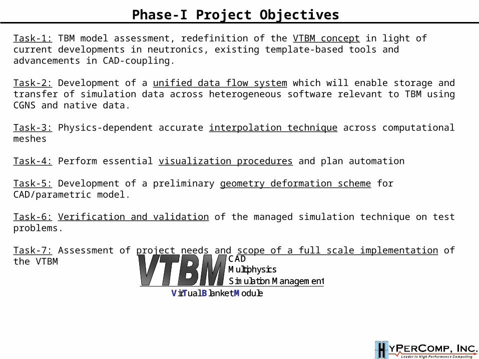
Phase-I Project Objectives
Task-1: TBM model assessment, redefinition of the VTBM concept in light of current developments in neutronics, existing template-based tools and advancements in CAD-coupling.
Task-2: Development of a unified data flow system which will enable storage and transfer of simulation data across heterogeneous software relevant to TBM using CGNS and native data.
Task-3: Physics-dependent accurate interpolation technique across computational meshes
Task-4: Perform essential visualization procedures and plan automation
Task-5: Development of a preliminary geometry deformation scheme for CAD/parametric model.
Task-6: Verification and validation of the managed simulation technique on test problems.
Task-7: Assessment of project needs and scope of a full scale implementation of the VTBM
CADMultiphysicsSimulation Management
VirTual Blanket Module
CADMultiphysicsSimulation Management
VirTual Blanket Module
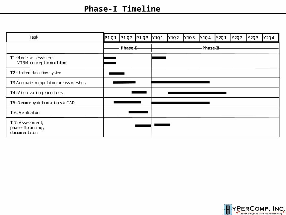
P1 Q1 P1 Q2 P1 Q3 Y2Q4Y2Q3Y2Q2Y2Q1Y1Q4Y1Q3Y1Q2Y1Q1P1 Q1 P1 Q2 P1 Q3 Y2Q4Y2Q3Y2Q2Y2Q1Y1Q4Y1Q3Y1Q2Y1Q1Task
T1: Model assessmentVTBM concept formulation
T2: Unified data flow system
T3:Accurate interpolation across meshes
T4: Visualization procedures
T5: Geometry deformation via CAD
T-6: Verification
T-7: Assessment, phase-II planning, documentation
Phase-I Phase-II
Phase-I Timeline
Related Documents


