Int. J. Adv. Res. Sci. Technol. Volume 3, Issue2, 2014, pp.111-118 # ICV 5.14 www.ijarst.com P.TulasiRadha.et.al Page | 111 International Journal of Advanced Research in Science and Technology journal homepage: www.ijarst.com ISSN 2319 – 1783 (Print) ISSN 2320 – 1126 (Online) Modeling Structural and Thermal Analysis of Conrod Using Composite Materials. P. Tulasi Radha*, T.Prakash Lazarus and I.Satyanarayana Department of Mechanical, Chaitanya College of Engineering, Visakhapatnam, India. *Corresponding Author’s Email: [email protected] A R T I C L E I N F O A B S T R A C T Article history: Received Accepted Available online 09Sept.2014 20 Sept.2014 24Sept.2014 The connecting rod is the intermediate member between the piston and the Crankshaft. It’s primary function is to transmit the push and pull from the piston pin to the crank pin, thus converting the reciprocating motion of the piston into rotary motion of the crank. Existing connecting rod is manufactured by using Forged steel. This paper describes modeling and analysis of connecting rod. In this project connecting rod is replaced by Composite materials 6061-T6. A 2D drawing is drafted from the calculations. A parametric model of connecting rod is modeled using SOLIDWORKSV13-14 software. Analysis is also carried out by using SOLIDWORKS V13-14software. Finite element analysis of connecting rod is done by considering 20 materials. The best combination of parameters like Von misses stress and strain, displacement, Factor of safety and weight were done in SOLIDWORKS software. Compared to Forged steel and other materials6061-T6 is found to have working factor of safety is nearer to theoretical factor, reduced weight, increased stiffness and reduced stress. © 2014 International Journal of Advanced Research in Science and Technology (IJARST). All rights reserved. Keywords: Conrod, Structural analysis, Thermal Analysis, Forged steel, 6061-T6, Modeling, Analysis of connecting rod. Introduction: Connecting rods are also known as Conrods. Connecting rods are widely used in variety of engines. The function of connecting rod is to transmit the thrust of the piston to the crank shaft, and as the result the reciprocating motion of the piston is translated into rotational motion of the crank shaft. It consist of a pin - end. A shank section, and crank an end .Pin end and crank end holes are machined to permit accurate fitting of bearings. One end of the connecting rod is connected to the piston by the piston pin. Connecting rods are subjected to forces generated by mass and fuel combustion .Theses two forces results in axial load and bending stresses. A connecting rod must be capable of transmitting axial tension, axial compression, and bending stress caused by the thrust and full of the piston and by centrifugal force. Finite element (FEM) Modal is a modern way for fatigue analysis and estimation of the component .The influential component factors are able to change such as material .cross section conditions etc. The technology surrounding the methods of connecting rod production and materials used has rapidly advanced in the past 50 years. These advancements have enabled the auto industry to develop engines with more power and reliability while decreasing the volume of space they occupy. The industry must continue to challenge itself to advance connecting rod technology in order to propel the auto industry to manufacture more cost and fuel efficient vehicles. Connecting rod for automotive applications are typically manufactured by forging from either wrought steel or powder metal. Schematic diagram for connecting rod as shown in figure1. Figure: 1.Schematic Diagram of Conrod

Welcome message from author
This document is posted to help you gain knowledge. Please leave a comment to let me know what you think about it! Share it to your friends and learn new things together.
Transcript

Int. J. Adv. Res. Sci. Technol. Volume 3, Issue2, 2014, pp.111-118 # ICV 5.14
www.ijarst.com P.TulasiRadha.et.al Page | 111
International Journal of Advanced Research in
Science and Technology
journal homepage: www.ijarst.com
ISSN 2319 – 1783 (Print)
ISSN 2320 – 1126 (Online)
Modeling Structural and Thermal Analysis of Conrod Using Composite
Materials.
P. Tulasi Radha*, T.Prakash Lazarus and I.Satyanarayana
Department of Mechanical, Chaitanya College of Engineering, Visakhapatnam, India.
*Corresponding Author’s Email: [email protected]
A R T I C L E I N F O
A B S T R A C T
Article history:
Received
Accepted
Available online
09Sept.2014
20 Sept.2014
24Sept.2014
The connecting rod is the intermediate member between the piston and the
Crankshaft. It’s primary function is to transmit the push and pull from the
piston pin to the crank pin, thus converting the reciprocating motion of the
piston into rotary motion of the crank. Existing connecting rod is
manufactured by using Forged steel. This paper describes modeling and
analysis of connecting rod. In this project connecting rod is replaced by
Composite materials 6061-T6. A 2D drawing is drafted from the
calculations. A parametric model of connecting rod is modeled using
SOLIDWORKSV13-14 software. Analysis is also carried out by using
SOLIDWORKS V13-14software.
Finite element analysis of connecting rod is done by considering 20
materials. The best combination of parameters like Von misses stress and
strain, displacement, Factor of safety and weight were done in
SOLIDWORKS software. Compared to Forged steel and other
materials6061-T6 is found to have working factor of safety is nearer to
theoretical factor, reduced weight, increased stiffness and reduced stress.
© 2014 International Journal of Advanced Research in Science and Technology (IJARST).
All rights reserved.
Keywords: Conrod,
Structural analysis,
Thermal Analysis,
Forged steel,
6061-T6,
Modeling,
Analysis of connecting rod.
Introduction:
Connecting rods are also known as Conrods.
Connecting rods are widely used in variety of engines.
The function of connecting rod is to transmit the thrust
of the piston to the crank shaft, and as the result the
reciprocating motion of the piston is translated into
rotational motion of the crank shaft. It consist of a pin -
end. A shank section, and crank an end .Pin end and
crank end holes are machined to permit accurate fitting
of bearings. One end of the connecting rod is connected
to the piston by the piston pin. Connecting rods are
subjected to forces generated by mass and fuel
combustion .Theses two forces results in axial load and
bending stresses. A connecting rod must be capable of
transmitting axial tension, axial compression, and
bending stress caused by the thrust and full of the piston
and by centrifugal force. Finite element (FEM) Modal
is a modern way for fatigue analysis and estimation of
the component .The influential component factors are
able to change such as material .cross section
conditions etc.
The technology surrounding the methods of
connecting rod production and materials used has
rapidly advanced in the past 50 years. These
advancements have enabled the auto industry to
develop engines with more power and reliability while
decreasing the volume of space they occupy. The
industry must continue to challenge itself to advance
connecting rod technology in order to propel the auto
industry to manufacture more cost and fuel efficient
vehicles. Connecting rod for automotive applications
are typically manufactured by forging from either
wrought steel or powder metal. Schematic diagram for
connecting rod as shown in figure1.
Figure: 1.Schematic Diagram of Conrod
Int. J. Adv. Res. Sci. Technol. Volume 3, Issue2, 2014, pp.111-118 # ICV 5.14
www.ijarst.com P.TulasiRadha.et.al Page | 112
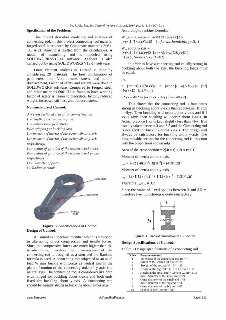
Specification of the Problem:
This project describes modeling and analysis of
connecting rod. In this project connecting rod material
forged steel is replaced by Composite materials 6061-
T6. A 2D drawing is drafted from the calculations. A
model of connecting rod is modeled using
SOLIDWORKSV13-14 software. Analysis is also
carried out by using SOLIDWORKS V13-14 software.
Finite element analysis of Conrod is done by
considering 20 materials. The best combination of
parameters like Von misses stress and strain,
displacement, Factor of safety and weight were done in
SOLIDWORKS software. Compared to Forged steel,
and other materials 6061-T6 is found to have working
factor of safety is nearer to theoretical factor , reduced
weight, increased stiffness and reduced stress.
Nomenclature of Conrod:
A = cross sectional area of the connecting rod.
L = length of the connecting rod.
C = compressive yield stress.
Wcr= crippling or buckling load.
Ixx= moment of inertia of the section about x-axis
Iyy= moment of inertia of the section about y-axis
respectively.
Kxx= radius of gyration of the section about x-axis
Kyy= radius of gyration of the section about y- axis
respectively.
D = Diameter of piston
r = Radius of crank
Figure: 2.Specifications of Conrod
Design of Conrod:
A Conrod is a machine member which is subjected
to alternating direct compressive and tensile forces.
Since the compressive forces are much higher than the
tensile force, therefore the cross-section of the
connecting rod is designed as a strut and the Rankine
formula is used. A connecting rod subjected to an axial
load W may buckle with x-axis as neutral axis in the
plane of motion of the connecting rod,{or} y-axis is a
neutral axis. The connecting rod is considered like both
ends hinged for buckling about x-axis and both ends
fixed for buckling about y-axis. A connecting rod
should be equally strong in buckling about either axis.
According to rankine formulae:
W crabout x-axis = [𝜎𝑐×𝐴]/1+[𝐿𝐾𝑥𝑥]2 =
[𝜎𝑐×𝐴]/1+𝑎[𝑙𝐾𝑥𝑥]2 [ ∴𝑓𝑜𝑟𝑏𝑜𝑡ℎ𝑒𝑛𝑑𝑠ℎ𝑖𝑛𝑔𝑒𝑑𝐿=𝑙]
Wcr about y-axis =
[𝜎𝑐×𝐴]/1+[𝐿𝐾𝑦𝑦]2=[𝜎𝑐×𝐴]/1+𝑎[𝑙2𝐾𝑦𝑦]2 [
∴𝑓𝑜𝑟𝑏𝑜𝑡ℎ𝑒𝑛𝑑𝑠𝑓𝑖𝑥𝑒𝑑𝐿=𝑙/2]
In order to have a connecting rod equally strong in
buckling about both the axis, the buckling loads must
be equal.
i.e.
= [𝜎𝑐×𝐴]/1+[𝑙𝐾𝑥𝑥]2 = [𝜎𝑐×𝐴]/1+𝑎[𝑙2𝐾𝑦𝑦]2 [or]
[𝑙/𝐾𝑥𝑥]2= [𝑙/2𝐾𝑦𝑦]2
K2xx = 4K
2yy [or] I xx = 4Iyy [∴𝐼=𝐴×𝐾2]
This shows that the connecting rod is four times
strong in buckling about y-axis than about-axis. If I xx
> 4Iyy, Then buckling will occur about y-axis and if I
xx < 4Iyy, then buckling will occur about x-axis .In
Actual practice I xx is kept slightly less than 4Iyy. It is
usually taken between 3 and 3.5 and the Connecting rod
is designed for buckling about x-axis. The design will
always be satisfactory for buckling about y-axis. The
most suitable section for the connecting rod is I-section
with the proportions shown mfg
Area of the cross section = 2[4t x t] + 3t x t=11t2
Moment of inertia about x-axis,
Ixx = 1/12 [ 4t(5t)3- 3t(3t)
3] = (419/12)t
4.
Moment of inertia about y-axis,
Iyy = [2×1/12×t(4t)3] + 1/12×3t×t
3 = (131/12)t
4
Therefore Ixx/Iyy = 3.2
Since the value of I xx/I yy lies between 3 and 3.5 m
therefore I-section chosen is quite satisfactory
Figure: 3 Standard Dimension of I – Section
Design Specifications of Conrod:
Table: 1 Design specifications of a connecting rod
S. No
Parameters(mm)
1 Thickness of the connecting rod (t) = 7 2 Width of the section (B = 4t) = 28
3 Height of the section(H = 5t) = 35
4 Height at the big end = (1.1 to 1.125)H = 38.5
5 Height at the small end = 0.9H to 0.75H= 31.5 6 Inner diameter of the small end = 29
7 Outer diameter of the small end = 43 8 Inner diameter of the big end = 44
9 Outer diameter of the big end = 65 10 Length of the Conrod = 380

Int. J. Adv. Res. Sci. Technol. Volume 3, Issue2, 2014, pp.111-118 # ICV 5.14
www.ijarst.com P.TulasiRadha.et.al Page | 113
Design of Conrod:
Solid Works is a 3D mechanical CAD (computer-
aided design) program that runs on Microsoft Windows
and is being developed by DassaultSystèmes Solid
Works Corporation. Dimensions of Width and height of
the Conrod are considered. A 3- D model of Conrod is
used for analysis in SOLIDWORKS V13-14. The
loading conditions are assumed to be static. Analysis
done with pressure load applied at the piston end and
restrained at the crank end or other load applied at the
crank end and restrained at the piston end. The element
chosen is 3-D SOLID, it was used with the tetrahedral
option, making it a 10-node element with 3 degrees of
freedom at each node.
Figure: 4.1Assembly of the Conrod
Figure: 4.2 Finite Element Mesh of the Conrod
Assembly
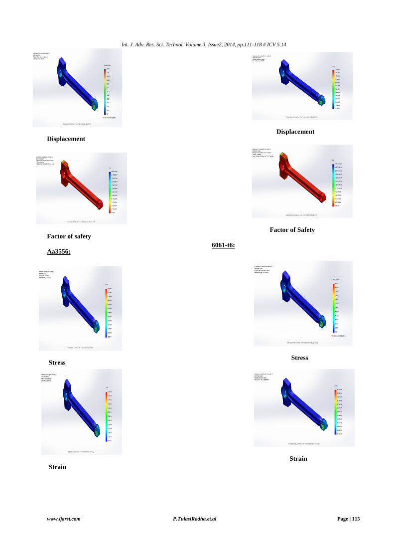
Structural Analysis of Conrod:
The finite element analysis is carried out on 20
elements for both Compressive and Tensile load. From the analysis the equivalent stress (Von-misesstress), strain, displacements, factor of safety, and weight were determined and are shown in figures from 5.1 - 5.4. Table 2 shows the comparative of various factors for 5 different materials. The comparison between the Forged
Steel and top 4 materials are shown with the figures and the graphs.
Table: 2. Static analysis of conrodAnalysis of stress for compressive load (3.15mpa):
S. No TYPE OF
MATERIAL
STRESS(N\m2) DISPLACEMENT(mm) STRAIN(mm) FOS WEIGHT
(Kg)
MIN MAX MIN MAX MIN MAX MIN MAX
1 6061-T6 0.817802 4628.05 2.1835*10^-11 4.188*10^-7 9.166*10^-12 4.1596*10^-8 65299.8 4.3409*10^8 1.043279
2 AA356 0.778319 4685.83 2.0876*10^-6 9.999*10^-7 2.9389*10^-7 9.8759*10^-8 33847.6 2.4411*10^8 0.928596
3 SILUMIN 0.759717 4710.54 7.8007*10^-11 5.2148*10^-7 1.0387*10^-11 5.1273*10^-8 39524.1 2.96163*10^8 0.940625
4 MAGNESIU
M
0.719186 4753.82 1.18662*10^-10 8.9494*10^-7 1.678*10^-11 8.7422*10^-8 16276 1.3209*10^8 0.601377
5 FORGED
STEEL
0.613154 4851.89 1.21428*10^-11 1.8199*10^-7 2.8788*10^-12 1.7454*10^-8 101059 1.01932*10^9 2.723879
Forged
Steel:
STRESS
STRAIN

Int. J. Adv. Res. Sci. Technol. Volume 3, Issue2, 2014, pp.111-118 # ICV 5.14
www.ijarst.com P.TulasiRadha.et.al Page | 114
Displacement
Factor of Safety
Magnesium:
Stress
Strain
displacement
factor of safety
Silumin:
Stress
Strain
Int. J. Adv. Res. Sci. Technol. Volume 3, Issue2, 2014, pp.111-118 # ICV 5.14
www.ijarst.com P.TulasiRadha.et.al Page | 115
Displacement
Factor of safety
Aa3556:
Stress
Strain
Displacement
Factor of Safety
6061-t6:
Stress
Strain

Int. J. Adv. Res. Sci. Technol. Volume 3, Issue2, 2014, pp.111-118 # ICV 5.14
www.ijarst.com P.TulasiRadha.et.al Page | 116
Displacement
Factor of safety
Thermal analysis of conrod
The Thermal analysis is also done for the different 20
materials based on the thermal conductivity of the
materials and the Table 3 shows the comparative study
for 5 materials.
Table:3. Thermal Analysis of conrod
SNO TYPE OF
MATERIAL
HEAT
FLUX
W/m2
TEMPERATURE(°K)
MIN MAX
1 6061-T6 1230526.315 2.46598*10^-9 487.57
2 AA356 112631.578 1.33696*10^-10 48.9884
3 SILUMIN 1008000 6.7063*10^-10 472.085
4 MAGNESIUM 1105263.158 1.83251 1536.79
5 FORGED
STEEL
1662.315 0.000128529 687.021
Forged Steel
Magnesium
Silumin
AA3566
6061-T6
GRAPHS
The graphs are drawn by considering the
forged steel and top 4 materials.

Int. J. Adv. Res. Sci. Technol. Volume 3, Issue2, 2014, pp.111-118 # ICV 5.14
www.ijarst.com P.TulasiRadha.et.al Page | 117
Conclusion
By checking and comparing the results of
materials from the above tables and finalizing the results
are shown in below:
By comparing all the five materials, 6061-T6,
AA356, SILUMIN, MAGNESIUM, FORGED
STEEL the material 6061-T6 have developed
less compressive stress when compared to the
other materials.
6061-T6 material has developed moderate
displacement when compared with the other
materials.
The weight of 6061-T6 material is very less
when compared to forged steel.
Thermal stresses for 6061-T6 material are less
when compared to forged steel
So this material (6061-T6) was concluded to
be the better material for the manufacturing of
Conrod’s.
Future Scope
Dynamic Analysis can be done by applying cyclic load.
Optimization can be performed to reduce weight
and manufacturing cost.
By using other facture crackable materials such
as micro-alloyed steels having higher yield
strength and endurance limit, the weight at the
piston pin end and the crank end can be further
reduced.
Large amount of CNTs adversely affect the
material strength.
0.00E+002.00E-074.00E-076.00E-078.00E-071.00E-061.20E-06
60
61
-T6
AA
35
6
SILU
MIN
MA
GN
ESIU
M
FOR
GED
STE
EL
DISPLACEMENT
DISPLACEMENT
450045504600465047004750480048504900
STRESS STRESS
0.00E+00
2.00E-08
4.00E-08
6.00E-08
8.00E-08
1.00E-07
1.20E-07
STRAIN
STRAIN
00.5
11.5
22.5
3
WEIGHT
WEIGHT
0200400600800
10001200140016001800
MAX TEMP
MAX TEMP

Int. J. Adv. Res. Sci. Technol. Volume 3, Issue2, 2014, pp.111-118 # ICV 5.14
www.ijarst.com P.TulasiRadha.et.al Page | 118
References:
1. Afzal, A., 2004, “Fatigue Behavior and
Life prediction of Forged Steel and PM
Connecting Rods,” Master’s Thesis, University
of Toledo.
2. Athavale, S. and Sajanpawar, P. R., 1991,
“Studies on Some Modeling Aspects in
theFinite Element Analysis of Small Gasoline
Engine Components,” Small Engine
Technology Conference Proceedings, Society
of Automotive Engineers of Japan, Tokyo,pp.
379-389.
3. Balasubramaniam, B., Svoboda, M., and
Bauer, W., 1991, “Structural optimization
ofI.C. engines subjected to mechanical and
thermal loads,” Computer Methods in
AppliedMechanics and Engineering, Vol. 89,
pp. 337-360.
4. Clark, J. P., Field III, F. R., and Nallicheri,
N. V., 1989, “Engine state-of-the-art a
competitive assessment of steel, cost estimates
and performance analysis,” Research Report BR
89-1, Automotive Applications Committee,
American Iron and Steel Institute.
5. El-Sayed, M. E. M., and Lund, E. H., 1990,
“Structural optimization with fatigue life
constraints,” Engineering Fracture Mechanics,
Vol. 37, No. 6, pp. 1149-1156.
6. Folgar, F., Wldrig, J. E., and Hunt, J. W.,
1987, “Design, Fabrication and Performance
ofFiber FP/Metal Matrix Composite Connecting
Rods,” SAE Technical Paper Series 1987,Paper
No. 870406
ABOUT AUTHORS
P.TULASI RADHA is a P.G student of Mechanical
Department of Chaitanya Engineering College. She
done her B.Tech from GITAM college of Engineering
affiliated to Andhra University.
Lazarus T. PrakashM.Tech (Ph.D) is presently
Professor & Head of the Department of Mechanical
Engineering Department, Chaitanya Engineering
College. He has vast experience in the field of teaching.
He has guided many projects for B.Tech&M.Tech
Students.
Prof[Dr]I.SATYANARAYANA,B.E.,M.E.,PGDAS.,FI
E,FIIP,MISTE,C[ENGG],,born in west
godavaridistrict, Andhra Pradesh, INDIA. He
receivedM.E.[machine design] from Andhra
University,VISAKHAPATNAM.AP, INDIA.He is
CHAIRMAN of''THE INSTITUTION OF
ENGINEERS[INDIA]VISAKHAPATNAM,centre,He
is also a council member of IEI.He has 35 years of
industrial experience and 10 years teaching experience
as professor in Mech.Engg..presently he is working
as professor in MechEnggdept,CHAITANYA
ENGG,COLLEGE VISAKHAPATNAM. INDIA
Related Documents