www.cafetinnova.org Indexed in Scopus Compendex and Geobase Elsevier, Chemical Abstract Services-USA, Geo-Ref Information Services-USA, List B of Scientific Journals, Poland, Directory of Research Journals ISSN 0974-5904, Volume 06, No. 05 October 2013, P.P. 923-939 #02050607 Copyright ©2013 CAFET-INNOVA TECHNICAL SOCIETY. All rights reserved. Modeling of PZ in accordance to the type of Connections in SMRF R. AHMADY JAZANY 1 AND A. GOLARA 1 1 International Institute of Earthquake Engineering and Seismology (IIEES), Tehran, Iran. Email: [email protected] , [email protected] Abstract: This study aims at evaluating and modeling the cyclic behavior of panel zone in Special Moment Resisting Frame (SMRF), according to their connection type, such as welded unreinforced flange-bolted web (WUF-B) connections, cover plate connection, one sided haunch and double sided haunches. In this research, some test specimens of experimental works conducted by SAC joint venture (report) were used to investigate the behavior of PZ. In the analytical models of this study, all component of connection including bolts, and weld are modeled using a surface contact for shear tab and bolt and shank, to evaluate the connection behavior precisely. Then analytical response of the model including cyclic behavior of beams and PZ obtained from analytical models and experimental models were used for training of Neural Network (N.N). Then new analytical data generated by Neural Network (N.N.) used for empirical modeling of PZ according to their corresponding connection types. The results of this study showed that the panel zone seismic behavior depends on the type of connections, and plastic and elastic shears strain values of panel zone changes regarding type of connections and the proposed model presented in this research predicts the panel zone seismic behavior accurately. Keywords: Panel zone, SMRF, WUF-B, Analytical models, cyclic behavior, Neural Network 1. Introduction: Moment resisting frames (MRFs) are widely used in steel structures as lateral force resisting system due to superior ductile behavior and energy absorption. MRFs behave in ductile manner through flexural yielding of beam and shear yielding of the panel zone. During of sever ground motion, a huge amount of plastic deformation is expected at each member in MRFs [1-5]. In Northridge earthquake, sever damage in welded connection of steel moment frames occurred. Nevertheless, the occurrence of the connection fractures has resulted in changes in design and construction of steel moment frames. The fracture of moment connection in the Northridge earthquake exhibits a variety of origins and path; In general, the fracture of beam to column joint initiates at the root of beam flange to column flange CJP groove weld and propagate through the beam flange, the column flange, or weld itself. In some instances fracture extended through column flange and web. The backing plate, which was generally left in place, produced a mechanical notch at the weld root and this may be a reason for connection fracture. Also based on last studies [1-5], the excessive shear strain of panel zone may result in CJP groove weld fracture; thus, the PZ seismic behavior can have a important role in controlling of fracture and yielding modes of the connection. Studies on Panel zone (PZ) behavior were initiated in the late 1960s and early 1970s to comprehend the inelastic behavior of joints in moment-resisting frames [1-5]. These studies indicated that the contribution of top displacement of the sub-assemblage was highly influenced by the panel zone distortion. Becker [5] also pointed out the importance of considering the influence of joint deformations of the frames in terms of stiffness and energy absorption. In addition, the effect of axial loads on the performance of connections subjected to shear was investigated. Several years later, Slutter [6] and Popov et al. [7-8] studied the extreme loading condition effects on the beam to column joint cyclic behavior. They showed that the column flange contributes the nonlinear behavior of the PZ effectively. They also emphasized that the PZ could have a high reserve of strength after yielding, high ductility and significant strain hardening properties. With regard to the high nonlinear capacity of PZ, these observations resulted in a decrease in the PZ demand that was specified in ICBO [9] and AISC [10]. These codes therefore capped at 80% the transferred shear corresponding to the beam plastic moment, but large distortions of the PZ could lead to local kinking of the column flange at the corner of the joints, where the beam flanges are connected to the column flanges. Results of a study by Tsai and Popov [11] indicated that panel zones designed according to the above-mentioned

Welcome message from author
This document is posted to help you gain knowledge. Please leave a comment to let me know what you think about it! Share it to your friends and learn new things together.
Transcript
www.cafetinnova.org
Indexed in
Scopus Compendex and Geobase Elsevier, Chemical
Abstract Services-USA, Geo-Ref Information Services-USA,
List B of Scientific Journals, Poland,
Directory of Research Journals
ISSN 0974-5904, Volume 06, No. 05 October 2013, P.P. 923-939
#02050607 Copyright ©2013 CAFET-INNOVA TECHNICAL SOCIETY. All rights reserved.
Modeling of PZ in accordance to the type of Connections in SMRF R. AHMADY JAZANY
1 AND A. GOLARA
1
1International Institute of Earthquake Engineering and Seismology (IIEES), Tehran, Iran.
Email: [email protected] , [email protected]
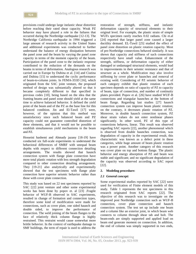
Abstract: This study aims at evaluating and modeling the cyclic behavior of panel zone in Special Moment
Resisting Frame (SMRF), according to their connection type, such as welded unreinforced flange-bolted web
(WUF-B) connections, cover plate connection, one sided haunch and double sided haunches. In this research, some
test specimens of experimental works conducted by SAC joint venture (report) were used to investigate the behavior
of PZ. In the analytical models of this study, all component of connection including bolts, and weld are modeled
using a surface contact for shear tab and bolt and shank, to evaluate the connection behavior precisely. Then
analytical response of the model including cyclic behavior of beams and PZ obtained from analytical models and
experimental models were used for training of Neural Network (N.N). Then new analytical data generated by Neural
Network (N.N.) used for empirical modeling of PZ according to their corresponding connection types. The results of
this study showed that the panel zone seismic behavior depends on the type of connections, and plastic and elastic
shears strain values of panel zone changes regarding type of connections and the proposed model presented in this
research predicts the panel zone seismic behavior accurately.
Keywords: Panel zone, SMRF, WUF-B, Analytical models, cyclic behavior, Neural Network
1. Introduction:
Moment resisting frames (MRFs) are widely used in
steel structures as lateral force resisting system due to
superior ductile behavior and energy absorption. MRFs
behave in ductile manner through flexural yielding of
beam and shear yielding of the panel zone. During of
sever ground motion, a huge amount of plastic
deformation is expected at each member in MRFs [1-5].
In Northridge earthquake, sever damage in welded
connection of steel moment frames occurred.
Nevertheless, the occurrence of the connection fractures
has resulted in changes in design and construction of
steel moment frames. The fracture of moment
connection in the Northridge earthquake exhibits a
variety of origins and path; In general, the fracture of
beam to column joint initiates at the root of beam flange
to column flange CJP groove weld and propagate
through the beam flange, the column flange, or weld
itself. In some instances fracture extended through
column flange and web. The backing plate, which was
generally left in place, produced a mechanical notch at
the weld root and this may be a reason for connection
fracture. Also based on last studies [1-5], the excessive
shear strain of panel zone may result in CJP groove
weld fracture; thus, the PZ seismic behavior can have a
important role in controlling of fracture and yielding
modes of the connection.
Studies on Panel zone (PZ) behavior were initiated in
the late 1960s and early 1970s to comprehend the
inelastic behavior of joints in moment-resisting frames
[1-5]. These studies indicated that the contribution of
top displacement of the sub-assemblage was highly
influenced by the panel zone distortion. Becker [5] also
pointed out the importance of considering the influence
of joint deformations of the frames in terms of stiffness
and energy absorption. In addition, the effect of axial
loads on the performance of connections subjected to
shear was investigated. Several years later, Slutter [6]
and Popov et al. [7-8] studied the extreme loading
condition effects on the beam to column joint cyclic
behavior. They showed that the column flange
contributes the nonlinear behavior of the PZ effectively.
They also emphasized that the PZ could have a high
reserve of strength after yielding, high ductility and
significant strain hardening properties. With regard to
the high nonlinear capacity of PZ, these observations
resulted in a decrease in the PZ demand that was
specified in ICBO [9] and AISC [10]. These codes
therefore capped at 80% the transferred shear
corresponding to the beam plastic moment, but large
distortions of the PZ could lead to local kinking of the
column flange at the corner of the joints, where the
beam flanges are connected to the column flanges.
Results of a study by Tsai and Popov [11] indicated that
panel zones designed according to the above-mentioned
924 Modeling of PZ in accordance to the type of Connections in SMRF
International Journal of Earth Sciences and Engineering
ISSN 0974-5904, Vol. 06, No. 05, October 2013, pp. 923-939
provisions could undergo large inelastic shear distortion
before reaching their rated shear capacity. Weak PZ
behavior may have played a role in the failures that
occurred during the Northridge earthquake [12-13]. The
Northridge California earthquake in 1994 triggered a
large amount of research activity in the United States
and additional experiments was conducted to further
understand the balance of energy dissipation between
the panel zone and the beam by varying the panel zone
capacity in terms of the moment capacity of the beam.
Participation of the panel zone to the inelastic response
contributed to the reduction of the demands on the
beams in terms of deformation. Analogous research was
carried out in Europe by Dubina et al. [14] and Ciutina
and Dubina [15] to understand the cyclic performance
of beam-to-column joints. In FEMA-355D [16], which
originated from the SAC joint venture, the proposed
method of design was substantially altered so that it
became completely different to that specified in
previous codes [10], being based on the idea that the
framing beams and panel zone should yield at the same
time to achieve balanced behavior. It defined the yield
point of the beam and of the PZ as the base line for this
balanced condition. Jin and El-Tawil [17] were,
however, of the opinion that this method was
unsatisfactory since such balanced beam and PZ
capacity could not guarantee controlled distortion of
these elements, and that it would not be possible to
establish simultaneous yield mechanisms in the beam
and PZ.
Hosseini hashemi and Ahmady jazany [18-19] have
conducted six full-scale experiments to understand the
behavioral differences of SMRF with unequal beam
depths with respect to different connection detailing
arrangements. The results showed that haunch
connection system with flange plate connection have
more total plastic rotation with less strength degradation
compared to other connection detailing arrangement.
They [19-21] also analytically and experimentally
showed that the test specimens with flange plate
connection have superior seismic behavior rather than
those with cover plate connection.
This study was based on 22 test specimens reported by
SAC [22] joint venture and other some experimental
works has been done by popov et. al [23] .Fragile
behavior of WUF-B observed in SAC experiments,
resulted in change of formation and connection types,
therefore some kind of modification were made for
connections, such as cover plate, one sided haunch and
double sided, to improve the performance of
connection. The weld joining of the beam flanges to the
face of relatively thick column flange is highly
restrained. This restraint would cause somewhat more
brittle behavior. In the context of earthquake damage to
SMF buildings, the term of repair is used to address the
restoration of strength, stiffness, and inelastic
deformation capacity of structural elements to their
original level. For example, the plastic strain of simple
WUFs specimen rarely reaches 0.02 radians. Chi et.al
[24] reported that larger panel zone caused a larger
ductility demand. EL-Tawil [25] studied the effect of
panel zone distortion on plastic rotation capacity. Most
of pre-Northridge connections behaved similarly. It was
shown that capacity and stiffness of such connections
respectively have small value. Enhancement of the
strength, stiffness, or deformation capacity of either
damaged or undamaged structural elements, would lead
to improvements in their seismic resistance and that of
structure as a whole. Modification may also involve
stiffening by cover plate or haunches and removal of
existing weld. Considering of PZ seismic behavior of
each category exhibit that plastic rotation of each
specimen depends on ratio of capacity of PZ to capacity
of beam, type of connection, and number of continuity
plates provided. Popov et al. [26] have studied WUF-B
connections and triangular haunches at the bottom of
beam flange. Regarding last studies [27] haunch
connection system can improve beam plastic rotation;
on the contrary, it decreases plastic rotation of PZ.
Moreover, in double haunch connection system, PZ
shear strain values do not enter nonlinear phases
significantly. In other word, PZ of this type of
connections behaves, linear. This result was observed
regarding SAC reports [22], another phenomenal which
is observed from double haunches connection, was
degradation of capacity in the experimental result, this
characteristic was known as a defect point in these
categories, while huge amount of beam plastic rotation
was a power point. Another category of this research
was cover plate on top and bottom flange. The plastic
behavior and energy absorption of PZ and beam was
stable and significant; and no significant degradation of
the capacity was observed according to SAC report
[22].
2. Modeling procedure:
2.1 General concept:
Some experimental studies reported by SAC [22] were
used for verification of Finite element models of this
study. Table 1 represents the test specimens in this
research originated from SAC reports [22]. The
objective of this research was to investigate on the
improved post Northridge connection such as WUF-B
connection, cover plate connection and haunch
connection system. The test set up include one beam
and a column like an exterior joint, in which beam web
connects to column through shear tab and bolt. The
beam-ends are simply supported and applied load on
beam end generate moment on connection. In addition,
the end of column was simply supported in two ends,
925 R. AHMADY JAZANY AND A. GOLARA
International Journal of Earth Sciences and Engineering
ISSN 0974-5904, Vol. 06, No. 05, October 2013, pp. 923-939
which reflect inflection point of column in actual
structure. All mechanical properties and geometries of
section has been presented in table 1.also Yield strength
(Fy) and ultimate strength (Fu) was included in this
table.
2.2 Finite element modeling:
ANSYS [28] multi-purpose finite element program was
used to perform the numerical modeling of connections.
FE models were implemented using the ANSYS
parametric design language. The geometrical and
mechanical properties of the connection model were
defined as parameters in ANSYS such as root opening
geometries and Yield strength (Fy) and ultimate strength
(FU). Numerical modeling of connection was performed
including the following considerations: Using eight-
node-first order SOLID45 elements; also, bolt shanks
are modeled using SOLID64 element. ANSYS can
model contact problem using contact pair element:
CONTA174 and TARGE 170 [28], which work together
in a way that there is no penetration occurrence during
the loading process. The interaction in adjacent surface
between shear tab and web are modeled using
mentioned contact element. Bolt heads and nuts are
modeled as hexagonal and similar to real shape to
simulate the frictional forces. Coulomb coefficient was
assumed as 0.3, which produce the best result. Nearly in
most of literature for class a type steel surfaces, the
coulomb coefficient is one third of the usual value of
.33, which is proposed. It means 0.1 is proper amount
for converging and yielding result, however, because of
some differences in type of steel grade, the best
agreement between analytical and experimental seismic
response was occurred when it is considered about 0.3.
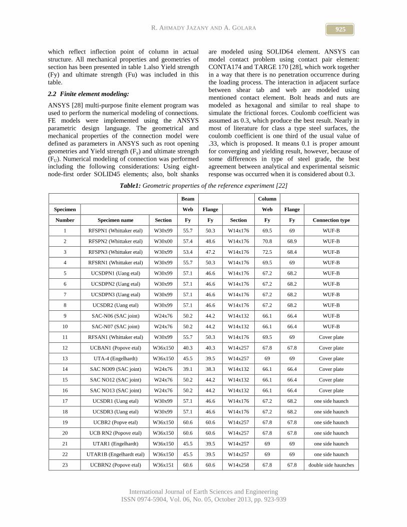
Table1: Geometric properties of the reference experiment [22]
Beam Column
Specimen Web Flange Web Flange
Number Specimen name Section Fy Fy Section Fy Fy Connection type
1 RFSPN1 (Whittaker etal) W30x99 55.7 50.3 W14x176 69.5 69 WUF-B
2 RFSPN2 (Whittaker etal) W30x00 57.4 48.6 W14x176 70.8 68.9 WUF-B
3 RFSPN3 (Whittaker etal) W30x99 53.4 47.2 W14x176 72.5 68.4 WUF-B
4 RFSRN1 (Whittaker etal) W30x99 55.7 50.3 W14x176 69.5 69 WUF-B
5 UCSDPN1 (Uang etal) W30x99 57.1 46.6 W14x176 67.2 68.2 WUF-B
6 UCSDPN2 (Uang etal) W30x99 57.1 46.6 W14x176 67.2 68.2 WUF-B
7 UCSDPN3 (Uang etal) W30x99 57.1 46.6 W14x176 67.2 68.2 WUF-B
8 UCSDR2 (Uang etal) W30x99 57.1 46.6 W14x176 67.2 68.2 WUF-B
9 SAC-N06 (SAC joint) W24x76 50.2 44.2 W14x132 66.1 66.4 WUF-B
10 SAC-N07 (SAC joint) W24x76 50.2 44.2 W14x132 66.1 66.4 WUF-B
11 RFSAN1 (Whittaker etal) W30x99 55.7 50.3 W14x176 69.5 69 Cover plate
12 UCBAN1 (Popove etal) W36x150 40.3 40.3 W14x257 67.8 67.8 Cover plate
13 UTA-4 (Engelhardt) W36x150 45.5 39.5 W14x257 69 69 Cover plate
14 SAC NO09 (SAC joint) W24x76 39.1 38.3 W14x132 66.1 66.4 Cover plate
15 SAC NO12 (SAC joint) W24x76 50.2 44.2 W14x132 66.1 66.4 Cover plate
16 SAC NO13 (SAC joint) W24x76 50.2 44.2 W14x132 66.1 66.4 Cover plate
17 UCSDR1 (Uang etal) W30x99 57.1 46.6 W14x176 67.2 68.2 one side haunch
18 UCSDR3 (Uang etal) W30x99 57.1 46.6 W14x176 67.2 68.2 one side haunch
19 UCBR2 (Popve etal) W36x150 60.6 60.6 W14x257 67.8 67.8 one side haunch
20 UCB RN2 (Popove etal) W36x150 60.6 60.6 W14x257 67.8 67.8 one side haunch
21 UTAR1 (Engelhardt) W36x150 45.5 39.5 W14x257 69 69 one side haunch
22 UTAR1B (Engelhardt etal) W36x150 45.5 39.5 W14x257 69 69 one side haunch
23 UCBRN2 (Popove etal) W36x151 60.6 60.6 W14x258 67.8 67.8 double side haunches
926 Modeling of PZ in accordance to the type of Connections in SMRF
International Journal of Earth Sciences and Engineering
ISSN 0974-5904, Vol. 06, No. 05, October 2013, pp. 923-939
24 UCBRN3 (Popove etal) W36x152 60.6 60.6 W14x258 67.8 67.8 double side haunches
25 UTA-3 (Engelhardt etal) W35x150 45.5 39.5 W14x257 69 69 double side haunches
2.3 Boundary condition and applied load:
To satisfy boundary condition of analytical model, the
end of beam was fixed against to the lateral
displacement. Also because of existing lateral bracing
system in real model on the flange of beam of test
specimen, some points at middle length of the beam
flanges of analytical models were fixed. Since there was
no information about the situation of bolt regarding pre-
tension or ordinary twisting of bolt, it was considered as
ordinary bolt which would not permit shear tab to slip
outward the plan of web. Displacement control was
used for loading of beams end, and loading pattern was
based on ATC 24 loading protocol [29], which was used
for reference experiments reported by SAC [22-23]
2.4 Material properties:
The material properties of these models had kinematic
behavior with strain hardening in nonlinear phase to
predict the material specification precisely. The stress-
strain curve for all connection components except for
the bolts was represented using a three-linear
constitutive model. An isotropic hardening rule with a
von Mises yielding criterion was used to simulate
plastic deformations of the analytical model. ASTM 36
steel was used for the beam and ASTM 52 steel was
utilized for the column and connection details. In the
current study, the mechanical properties of beam
column and connections are taken from table 1 [22].
The yield stress and ultimate strength of bolts are
assumed to be based on nominal properties of A325.
The yield stress and ultimate stress of weld are assumed
to be based on nominal properties of E71T-8(AWS
A5.20) [30]. Modulus of elasticity and Poisson’s ratio
was taken 29000 kips/in2 and 0.3.
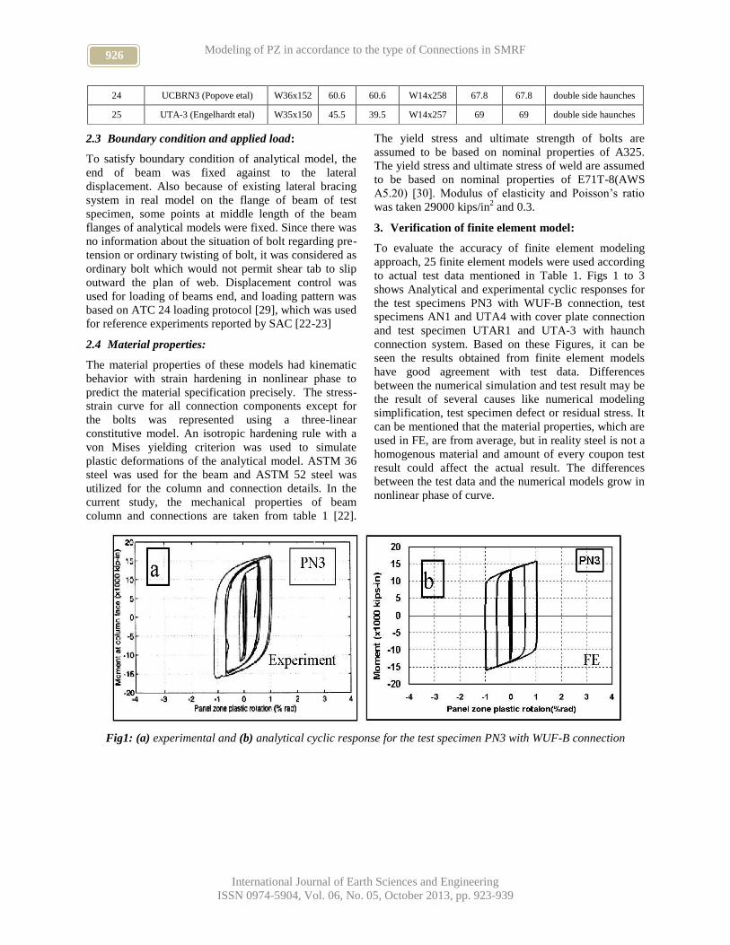
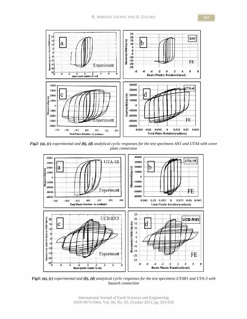
3. Verification of finite element model:
To evaluate the accuracy of finite element modeling
approach, 25 finite element models were used according
to actual test data mentioned in Table 1. Figs 1 to 3
shows Analytical and experimental cyclic responses for
the test specimens PN3 with WUF-B connection, test
specimens AN1 and UTA4 with cover plate connection
and test specimen UTAR1 and UTA-3 with haunch
connection system. Based on these Figures, it can be
seen the results obtained from finite element models
have good agreement with test data. Differences
between the numerical simulation and test result may be
the result of several causes like numerical modeling
simplification, test specimen defect or residual stress. It
can be mentioned that the material properties, which are
used in FE, are from average, but in reality steel is not a
homogenous material and amount of every coupon test
result could affect the actual result. The differences
between the test data and the numerical models grow in
nonlinear phase of curve.
Fig1: (a) experimental and (b) analytical cyclic response for the test specimen PN3 with WUF-B connection
927 R. AHMADY JAZANY AND A. GOLARA
International Journal of Earth Sciences and Engineering
ISSN 0974-5904, Vol. 06, No. 05, October 2013, pp. 923-939
Fig2: (a), (c) experimental and (b), (d) analytical cyclic responses for the test specimens AN1 and UTA4 with cover
plate connection
Fig3: (a), (c) experimental and (b), (d) analytical cyclic responses for the test specimens UTAR1 and UTA-3 with
haunch connection
928 Modeling of PZ in accordance to the type of Connections in SMRF
International Journal of Earth Sciences and Engineering
ISSN 0974-5904, Vol. 06, No. 05, October 2013, pp. 923-939
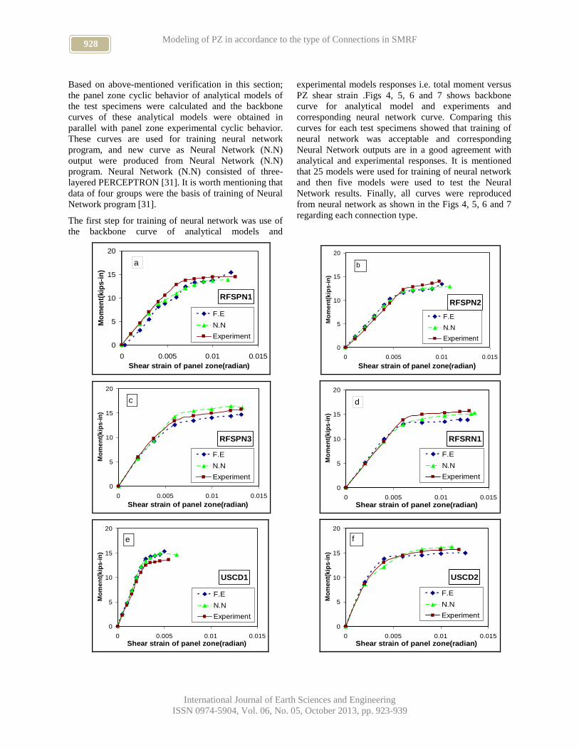
Based on above-mentioned verification in this section;
the panel zone cyclic behavior of analytical models of
the test specimens were calculated and the backbone
curves of these analytical models were obtained in
parallel with panel zone experimental cyclic behavior.
These curves are used for training neural network
program, and new curve as Neural Network (N.N)
output were produced from Neural Network (N.N)
program. Neural Network (N.N) consisted of three-
layered PERCEPTRON [31]. It is worth mentioning that
data of four groups were the basis of training of Neural
Network program [31].
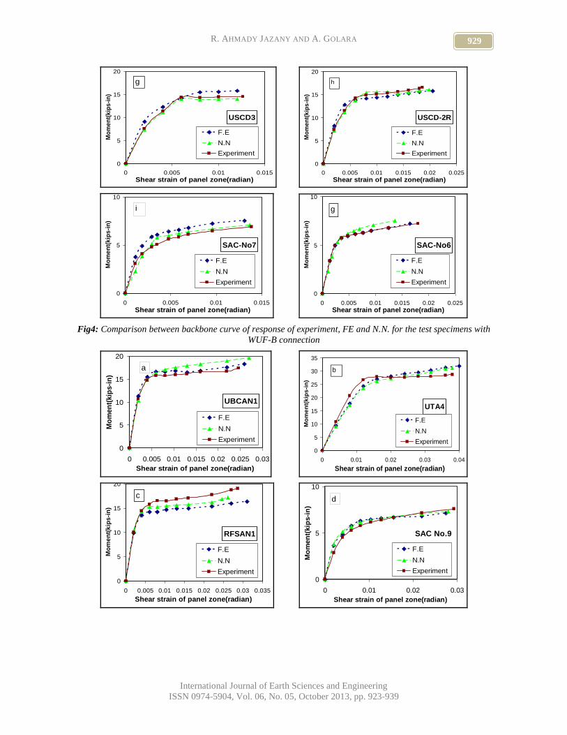
The first step for training of neural network was use of
the backbone curve of analytical models and
experimental models responses i.e. total moment versus
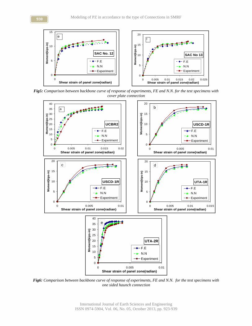
PZ shear strain .Figs 4, 5, 6 and 7 shows backbone
curve for analytical model and experiments and
corresponding neural network curve. Comparing this
curves for each test specimens showed that training of
neural network was acceptable and corresponding
Neural Network outputs are in a good agreement with
analytical and experimental responses. It is mentioned
that 25 models were used for training of neural network
and then five models were used to test the Neural
Network results. Finally, all curves were reproduced
from neural network as shown in the Figs 4, 5, 6 and 7
regarding each connection type.
RFSPN1
0
5
10
15
20
0 0.005 0.01 0.015
Shear strain of panel zone(radian)
Mo
men
t(kip
s-i
n)
F.E
N.N
Experiment
a
RFSPN2
0
5
10
15
20
0 0.005 0.01 0.015
Shear strain of panel zone(radian)
Mo
me
nt(
kip
s-i
n)
F.E
N.N
Experiment
b
RFSPN3
0
5
10
15
20
0 0.005 0.01 0.015
Shear strain of panel zone(radian)
Mo
me
nt(
kip
s-i
n)
F.E
N.N
Experiment
c
RFSRN1
0
5
10
15
20
0 0.005 0.01 0.015
Shear strain of panel zone(radian)
Mo
me
nt(
kip
s-i
n)
F.E
N.N
Experiment
d
USCD1
0
5
10
15
20
0 0.005 0.01 0.015
Shear strain of panel zone(radian)
Mo
me
nt(
kip
s-i
n)
F.E
N.N
Experiment
e
USCD2
0
5
10
15
20
0 0.005 0.01 0.015
Shear strain of panel zone(radian)
Mo
me
nt(
kip
s-i
n)
F.E
N.N
Experiment
f
929 R. AHMADY JAZANY AND A. GOLARA
International Journal of Earth Sciences and Engineering
ISSN 0974-5904, Vol. 06, No. 05, October 2013, pp. 923-939
USCD3
0
5
10
15
20
0 0.005 0.01 0.015
Shear strain of panel zone(radian)
Mo
me
nt(
kip
s-i
n)
F.E
N.N
Experiment
g
USCD-2R
0
5
10
15
20
0 0.005 0.01 0.015 0.02 0.025
Shear strain of panel zone(radian)
Mo
me
nt(
kip
s-i
n)
F.E
N.N
Experiment
h
SAC-No7
0
5
10
0 0.005 0.01 0.015
Shear strain of panel zone(radian)
Mo
me
nt(
kip
s-i
n)
F.E
N.N
Experiment
i
SAC-No6
0
5
10
0 0.005 0.01 0.015 0.02 0.025
Shear strain of panel zone(radian)M
om
en
t(k
ips
-in
)
F.E
N.N
Experiment
g
Fig4: Comparison between backbone curve of response of experiment, FE and N.N. for the test specimens with
WUF-B connection
UBCAN1
0
5
10
15
20
0 0.005 0.01 0.015 0.02 0.025 0.03
Shear strain of panel zone(radian)
Mo
men
t(kip
s-i
n)
F.E
N.N
Experiment
a
UTA4
0
5
10
15
20
25
30
35
0 0.01 0.02 0.03 0.04
Shear strain of panel zone(radian)
Mo
me
nt(
kip
s-i
n)
F.E
N.N
Experiment
b
RFSAN1
0
5
10
15
20
0 0.005 0.01 0.015 0.02 0.025 0.03 0.035
Shear strain of panel zone(radian)
Mo
me
nt(
kip
s-i
n)
F.E
N.N
Experiment
c
SAC No.9
0
5
10
0 0.01 0.02 0.03
Shear strain of panel zone(radian)
Mo
men
t(kip
s-i
n)
F.E
N.N
Experiment
d
930 Modeling of PZ in accordance to the type of Connections in SMRF
International Journal of Earth Sciences and Engineering
ISSN 0974-5904, Vol. 06, No. 05, October 2013, pp. 923-939
SAC No. 12
0
5
10
15
0
Shear strain of panel zone(radian)
Mo
me
nt(
kip
s-i
n)
F.E
N.N
Experiment
e
SAC No 13
0
5
10
15
20
0 0.005 0.01 0.015 0.02 0.025
Shear strain of panel zone(radian)
Mo
me
nt(
kip
s-i
n)
F.E
N.N
Experiment
f
Fig5: Comparison between backbone curve of response of experiments, FE and N.N. for the test specimens with
cover plate connection
UCBR2
0
5
10
15
20
25
30
35
40
0 0.005 0.01 0.015 0.02
Shear strain of panel zone(radian)
Mo
me
nt(
kip
s-i
n)
F.E
N.N
Experiment
a
USCD-1R
0
5
10
15
20
0 0.005 0.01
Shear strain of panel zone(radian)
Mo
me
nt(
kip
s-i
n)
F.E
N.N
Experiment
b
USCD-1R
0
5
10
15
20
0 0.005 0.01
Shear strain of panel zone(radian)
Mo
me
nt(
kip
s-i
n)
F.E
N.N
Experiment
c
UTA-1R
0
5
10
15
20
0 0.005 0.01 0.015
Shear strain of panel zone(radian)
Mo
me
nt(
kip
s-i
n)
F.E
N.N
Experiment
d
UTA-2R
0
5
10
15
20
25
30
35
40
0 0.005 0.01
Shear strain of panel zone(radian)
Mo
me
nt(
kip
s-i
n)
F.E
N.N
Experiment
e
Fig6: Comparison between backbone curve of response of experiments, FE and N.N. for the test specimens with
one sided haunch connection
931 R. AHMADY JAZANY AND A. GOLARA
International Journal of Earth Sciences and Engineering
ISSN 0974-5904, Vol. 06, No. 05, October 2013, pp. 923-939
UCBRN1
0
5
10
15
20
25
0 0.005
Shear strain of panel zone(radian)
Mo
me
nt(
kip
s-i
n)
F.E
N.N
Experiment
a
UCBRN2
0
5
10
15
20
25
0 0.005
Shear strain of panel zone(radian)
Mo
me
nt(
kip
s-i
n)
F.E
N.N
Experiment
b
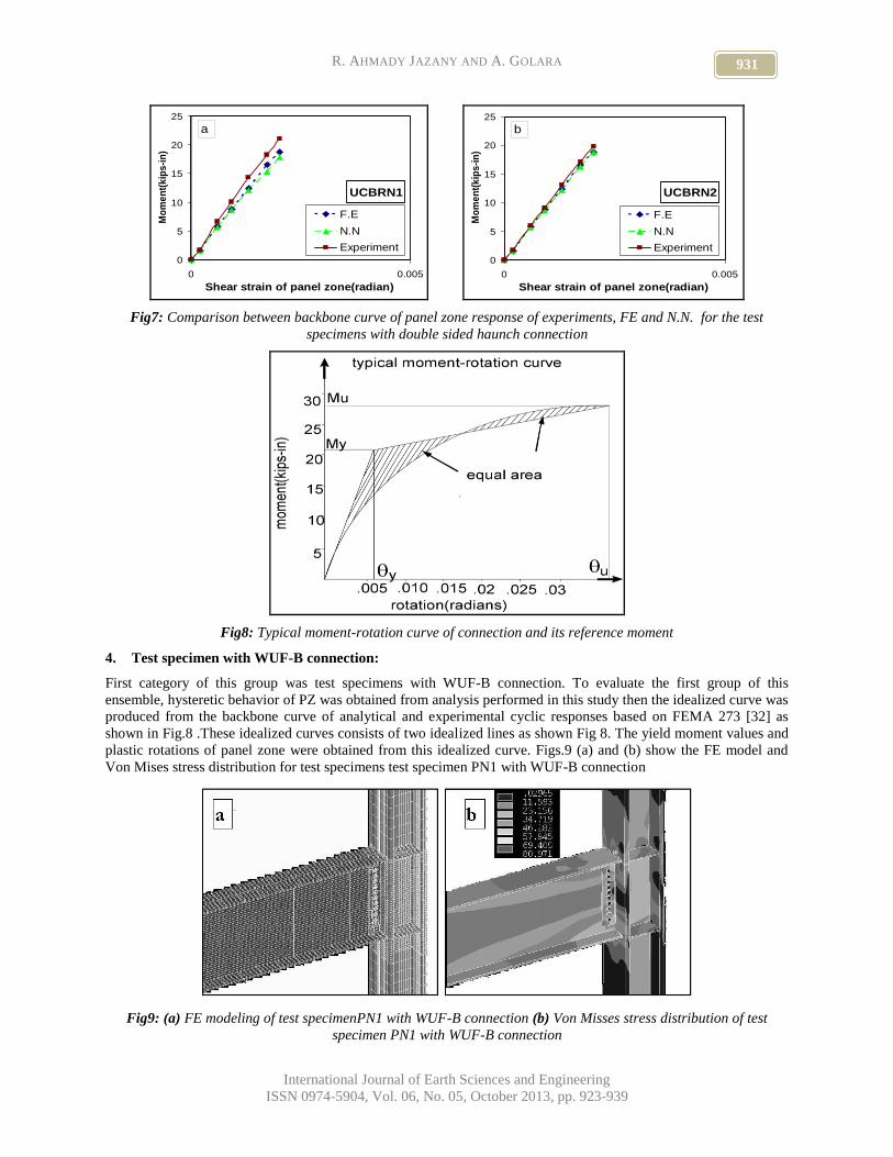
Fig7: Comparison between backbone curve of panel zone response of experiments, FE and N.N. for the test
specimens with double sided haunch connection
Fig8: Typical moment-rotation curve of connection and its reference moment
4. Test specimen with WUF-B connection:
First category of this group was test specimens with WUF-B connection. To evaluate the first group of this
ensemble, hysteretic behavior of PZ was obtained from analysis performed in this study then the idealized curve was
produced from the backbone curve of analytical and experimental cyclic responses based on FEMA 273 [32] as
shown in Fig.8 .These idealized curves consists of two idealized lines as shown Fig 8. The yield moment values and
plastic rotations of panel zone were obtained from this idealized curve. Figs.9 (a) and (b) show the FE model and
Von Mises stress distribution for test specimens test specimen PN1 with WUF-B connection
Fig9: (a) FE modeling of test specimenPN1 with WUF-B connection (b) Von Misses stress distribution of test
specimen PN1 with WUF-B connection
932 Modeling of PZ in accordance to the type of Connections in SMRF
International Journal of Earth Sciences and Engineering
ISSN 0974-5904, Vol. 06, No. 05, October 2013, pp. 923-939
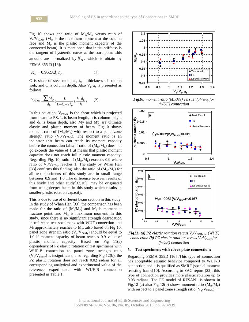
Fig 10 shows and ratio of Mm/Mp versus ratio of
Vy/VPZMy (Mm is the maximum moment at the column
face and Mp is the plastic moment capacity of the
connected beam). It is mentioned that initial stiffness is
the tangent of hysteretic curve at the start point .this
amount are normalized by GK , which is obtain by
FEMA 355-D [16]:
wcG tdGK ...95.0 (1)
G is shear of steel modulus, tw is thickness of column
web, and dc is column depth. Also VpzMy is presented as
follows:
))(2
(h
dh
ldL
L
d
MV b
pcb
yPZMy
(2)
In this equation; VPZMY is the shear which is projected
from beam to PZ, L is beam length, h is column height
and db is beam depth, also My and Mp are ultimate
elastic and plastic moment of beam. Fig.10 shows
moment ratio of (Mm/MP) with respect to a panel zone
strength ratio (Vy/VPZMy). The moment ratio is an
indicator that beam can reach its moment capacity
before the connection fails; if ratio of (Mm/Mp) does not
go exceeds the value of 1 ,it means that plastic moment
capacity does not reach full plastic moment capacity.
Regarding Fig. 10, ratio of (Mm/Mp) exceeds 0.9 where
ratio of Vy/VPZMy reaches 1. The study by Whan Han
[33] confirms this finding. also the ratio of (Mm/Mp) for
all test specimens of this study are in small range
between 0.9 and 1.0 .The difference between results of
this study and other study[33,16] may be originated
from using deeper beam in this study which results in
smaller plastic rotation capacity.
This is due to use of different beam section in this study.
In the study of Whan Han [33], the comparison has been
made for the ratio of (Mf/MP) and Mf is moment at
fracture point, and Mm is maximum moment. In this
study, since there is no significant strength degradation
in reference test specimens with WUF connection and
Mf approximately reaches to Mm .also based on Fig 10,
panel zone strength ratio (Vy/VPZMy) should be equal to
1.0 if moment capacity of beam reaches 0.9 value of
plastic moment capacity. Based on Fig 11(a)
dependency of PZ elastic rotation of test specimens with
WUF-B connection to panel zone strength ratio
(Vy/VPZMy) is insignificant, also regarding Fig 12(b), the
PZ plastic rotation does not reach 0.02 radian for all
corresponding analytical and experimental value of the
reference experiments with WUF-B connection
presented in Table 1.
0.75
0.8
0.85
0.9
0.95
1
1.05
1.1
0.8 0.9 1 1.1 1.2 1.3 1.4
Vy/VpzMy
Mf/M
p
Test result
FE
Neural Network
Fig10: moment ratio (Mm/MP) versus Vy/VPZMy for
(WUF) connection
y=-.0062(Vy/VpzMy)+0.011
0
0.005
0.01
0.015
0.02
0.8 1 1.2 1.4
Vy/VpzMy
PZ
,ela
sti
c r
ota
tio
n,
y
Test Result
FE
Neural Network
a
p=-.0081(V/VpzMy)+.0167
0
0.01
0.02
0.03
0.04
0.05
0.06
0.8 0.9 1 1.1 1.2 1.3 1.4
Vy/VpzMyz
PZ
pla
sti
c r
ota
tio
n,
pz
Test Result
FE
Neural Network
b
Fig11: (a) PZ elastic rotation versus Vy/VPZMy for (WUF)
connection (b) PZ elastic rotation versus Vy/VPZMy for
(WUF) connection
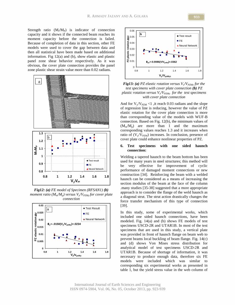
5. Test specimens with cover plate connection:
Regarding FEMA 355D [16] ,This type of connection
has acceptable seismic behavior compared to WUF-B
connection and it is qualified as SMRF (special moment
resisting frame[10]. According to SAC report [22], this
type of connection provides more plastic rotation up to
0.03 radians. The FE model of RFSAN1 is shown in
Fig.12 (a) also Fig 12(b) shows moment ratio (Mm/MP)
with respect to a panel zone strength ratio (Vy/VPZMy).
933 R. AHMADY JAZANY AND A. GOLARA
International Journal of Earth Sciences and Engineering
ISSN 0974-5904, Vol. 06, No. 05, October 2013, pp. 923-939
Strength ratio (Mf/MP) is indicator of connection
capacity and it shows if the connected beam reaches its
moment capacity before the connection is failed.
Because of completion of data in this section, other FE
models were used to cover the gap between data and
then all statistical have been made based on additional
information. Fig 12(a) and (b), show elastic and plastic
panel zone shear behavior respectively. As it was
obvious, the cover plate connection provides the panel
zone plastic shear strain value more than 0.02 radians.
0.8
0.9
1
1.1
1.2
1.3
0.8 1 1.2 1.4 1.6 1.8
Vy/Vpz
Mf/M
p
Test result
FE
Neural Network
b
Fig12: (a) FE model of Specimen (RFSAN1) (b)
moment ratio (Mm/Mp) versus Vy/VPZMy for cover plate
connection
y=-.0150(Vy/VpzMy)+.0234
0
0.005
0.01
0.015
0.02
0.025
0.03
0.8 1 1.2 1.4 1.6 1.8
Vy/vpzMy
PZ
ela
sti
c r
ota
tio
n,
y
Test Result
FE
Neural Network
a
pz=-0.0086(V/VpzMy)+.0362
0
0.01
0.02
0.03
0.04
0.05
0.06
0.8 1 1.2 1.4 1.6 1.8
Vy/VpzMyz
PZ
pla
sti
c r
ota
tio
n,
pz Test result
FE
Neural Network
b
Fig13: (a) PZ elastic rotation versus Vy/VPZMy for the
test specimens with cover plate connection (b) PZ
plastic rotation versus Vy/VPZMy for the test specimens
with cover plate connection
And for Vy/VPZM <1 ,it reach 0.03 radians and the slope
of regression line is reducing, however the value of PZ
elastic rotation for the cover plate connection is more
than corresponding value of the models with WUF-B
connection. Based on Fig. 12(b), the minimum values of
(Mm/Mp) are more than 1 and the maximum
corresponding values reaches 1.3 and it increases when
ratio of (Vy/VPZM) increases. In conclusion, presence of
cover plate could enhance nonlinear properties of PZ.
6. Test specimens with one sided haunch
connection:
Welding a tapered haunch to the beam bottom has been
used for many years in steel structures; this method will
be very effective for improvement of cyclic
performance of damaged moment connections or new
construction [34]. Reinforcing the beam with a welded
haunch can be considered as a means of increasing the
section modulus of the beam at the face of the column
.many studies [35-38] suggested that a more appropriate
approach is to consider the flange of the weld haunch as
a diagonal strut. The strut action drastically changes the
force transfer mechanism of this type of connection
[39].
In this study, some of experimental works, which
included one sided haunch connections, have been
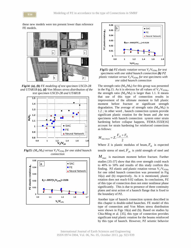
modeled. Fig. 14(a) and (b) shows FE models of test
specimens USCD-2R and UTAR1B. In most of the test
specimens that are used in this study, a vertical plate
was provided in front of haunch flange on beam web to
prevent beams local buckling of beam flange. Fig. 14(c)
and (d) shows Von Mises stress distribution for
analytical model of test specimens USCD-2R and
UTAR1B. Because of shortage of information, it was
necessary to produce enough data, therefore six FE
models were included which was similar to
corresponding six experimental works as presented in
table 1, but the yield stress value in the web column of
934 Modeling of PZ in accordance to the type of Connections in SMRF
International Journal of Earth Sciences and Engineering
ISSN 0974-5904, Vol. 06, No. 05, October 2013, pp. 923-939
these new models were ten present lower than reference
FE models.
Fig14: (a), (b) FE modeling of test specimen USCD-2R
and UTAR1B (c), (d) Von Misses stress distribution of the
test specimen USCD-2R and UTAR1B
0.8
0.9
1
1.1
1.2
1.3
1.4
1.5
0.8 1 1.2 1.4 1.6 1.8
Vy/Vpz
Mf/M
p
SAC
FE
Neural Network
Fig15: (Mm/MP) versus Vy/VPZMy for one sided haunch
connection
y=-.0057(Vy/VpzMy)+.0106
0
0.01
0.02
0.03
0.04
0.05
0.9 1.1 1.3 1.5 1.7
Vy/VpzMy
PZ
ela
sti
c r
ota
tio
n,
y
SAC
FE
Neural Network
a
pz=-.0065(V/VpzMy)+0.0126
0
0.01
0.02
0.03
0.04
0.05
0.06
0.8 1 1.2 1.4 1.6 1.8
Vy/VpzMyz
PZ
pla
sti
cro
tati
on
, p
z
SAC
FE
Neural Network
b
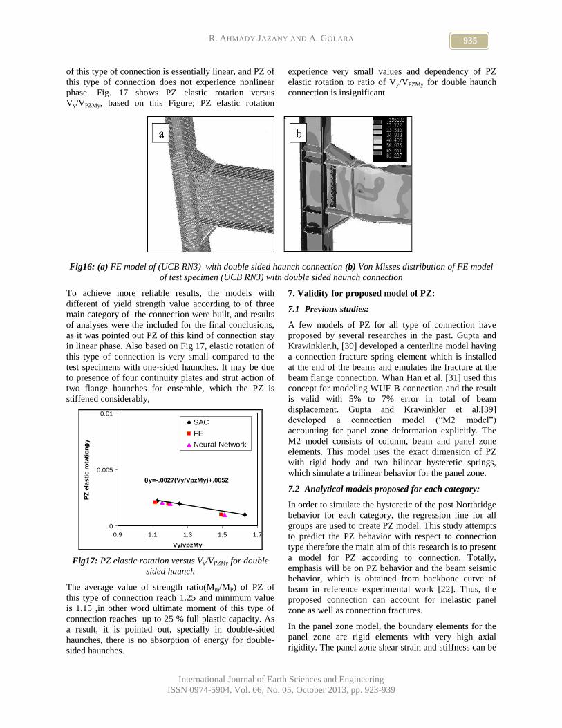
Fig15: (a) PZ elastic rotation versus Vy/VPZMy for test
specimens with one sided haunch connection (b) PZ
plastic rotation versus Vy/VPZMy for test specimens with
one sided haunch connection
The strength ratio (Mm/MP) for this group was presented
in the Fig.15. As it is obvious for all values of Vy/VPZMy,
the strength ratio (Mm/MP) is larger than 1.1. It means
that use of this type of connection results in
improvement of the ultimate moment to full plastic
moment before fracture or significant strength
degradation. The average of strength ratio (Mm/MP) is
1.2 ; in other word , haunch connection system provide
significant plastic rotation for the beam and ,the test
specimens with haunch connection system enter strain
hardening before collapse happens, FEMA-355D[16]
account for strain hardening for reinforced connections
as follows:
2.max
tbyb
imum
FFZM
Where Z is plastic modulus of beam, tbF is expected
tensile stress of steel, ybF is yield strength of steel and
maxM is maximum moment before fracture. Further
studies [35-37] show that this over strength could reach
to 40% to 50% and results of this study confirm this
finding. PZ elastic and plastic rotation versus Vy/VPZMy
for one sided haunch connection was presented in Fig
16(a) and (b) respectively. As it is mentioned, plastic
rotation does not reach 0.02 radians. In conclusions, PZ
of this type of connection does not enter nonlinear phase
significantly. This is due to presence of three continuity
plates and strut action of a haunch flange that is fixed to
the boundary of PZ.
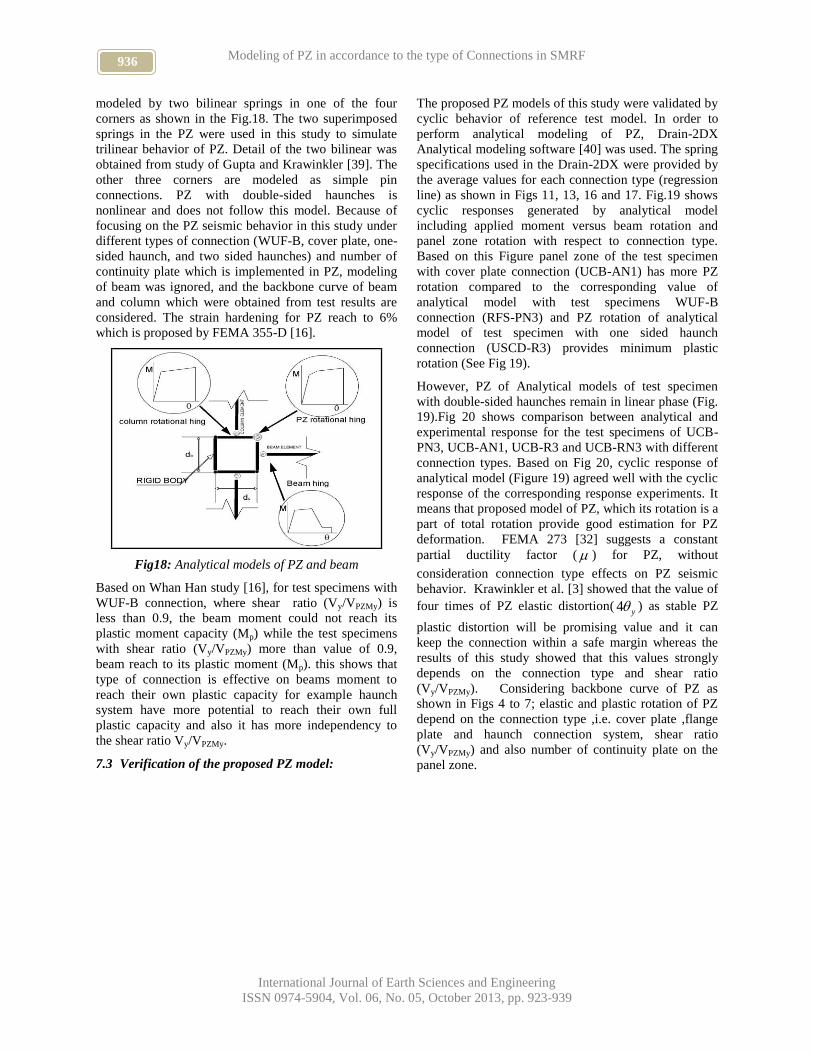
Another type of haunch connection system described in
this chapter is double-sided haunches. FE model of this
type of connection and Von Mises stress distribution
were shown in Figs 16(a) and (b). Based on studies by
Chia-Ming et al. [35], this type of connection provides
significant total plastic rotation for the beams reinforced
by this type of haunch. However, PZ seismic behavior
935 R. AHMADY JAZANY AND A. GOLARA
International Journal of Earth Sciences and Engineering
ISSN 0974-5904, Vol. 06, No. 05, October 2013, pp. 923-939
of this type of connection is essentially linear, and PZ of
this type of connection does not experience nonlinear
phase. Fig. 17 shows PZ elastic rotation versus
Vy/VPZMy, based on this Figure; PZ elastic rotation
experience very small values and dependency of PZ
elastic rotation to ratio of Vy/VPZMy for double haunch
connection is insignificant.
Fig16: (a) FE model of (UCB RN3) with double sided haunch connection (b) Von Misses distribution of FE model
of test specimen (UCB RN3) with double sided haunch connection
To achieve more reliable results, the models with
different of yield strength value according to of three
main category of the connection were built, and results
of analyses were the included for the final conclusions,
as it was pointed out PZ of this kind of connection stay
in linear phase. Also based on Fig 17, elastic rotation of
this type of connection is very small compared to the
test specimens with one-sided haunches. It may be due
to presence of four continuity plates and strut action of
two flange haunches for ensemble, which the PZ is
stiffened considerably,
y=-.0027(Vy/VpzMy)+.0052
0
0.005
0.01
0.9 1.1 1.3 1.5 1.7
Vy/vpzMy
PZ
ela
sti
c r
ota
tio
n,
y
SAC
FE
Neural Network
Fig17: PZ elastic rotation versus Vy/VPZMy for double
sided haunch
The average value of strength ratio(Mm/MP) of PZ of
this type of connection reach 1.25 and minimum value
is 1.15 ,in other word ultimate moment of this type of
connection reaches up to 25 % full plastic capacity. As
a result, it is pointed out, specially in double-sided
haunches, there is no absorption of energy for double-
sided haunches.
7. Validity for proposed model of PZ:
7.1 Previous studies:
A few models of PZ for all type of connection have
proposed by several researches in the past. Gupta and
Krawinkler.h, [39] developed a centerline model having
a connection fracture spring element which is installed
at the end of the beams and emulates the fracture at the
beam flange connection. Whan Han et al. [31] used this
concept for modeling WUF-B connection and the result
is valid with 5% to 7% error in total of beam
displacement. Gupta and Krawinkler et al.[39]
developed a connection model (“M2 model”)
accounting for panel zone deformation explicitly. The
M2 model consists of column, beam and panel zone
elements. This model uses the exact dimension of PZ
with rigid body and two bilinear hysteretic springs,
which simulate a trilinear behavior for the panel zone.
7.2 Analytical models proposed for each category:
In order to simulate the hysteretic of the post Northridge
behavior for each category, the regression line for all
groups are used to create PZ model. This study attempts
to predict the PZ behavior with respect to connection
type therefore the main aim of this research is to present
a model for PZ according to connection. Totally,
emphasis will be on PZ behavior and the beam seismic
behavior, which is obtained from backbone curve of
beam in reference experimental work [22]. Thus, the
proposed connection can account for inelastic panel
zone as well as connection fractures.
In the panel zone model, the boundary elements for the
panel zone are rigid elements with very high axial
rigidity. The panel zone shear strain and stiffness can be
936 Modeling of PZ in accordance to the type of Connections in SMRF
International Journal of Earth Sciences and Engineering
ISSN 0974-5904, Vol. 06, No. 05, October 2013, pp. 923-939
modeled by two bilinear springs in one of the four
corners as shown in the Fig.18. The two superimposed
springs in the PZ were used in this study to simulate
trilinear behavior of PZ. Detail of the two bilinear was
obtained from study of Gupta and Krawinkler [39]. The
other three corners are modeled as simple pin
connections. PZ with double-sided haunches is
nonlinear and does not follow this model. Because of
focusing on the PZ seismic behavior in this study under
different types of connection (WUF-B, cover plate, one-
sided haunch, and two sided haunches) and number of
continuity plate which is implemented in PZ, modeling
of beam was ignored, and the backbone curve of beam
and column which were obtained from test results are
considered. The strain hardening for PZ reach to 6%
which is proposed by FEMA 355-D [16].
Fig18: Analytical models of PZ and beam
Based on Whan Han study [16], for test specimens with
WUF-B connection, where shear ratio (Vy/VPZMy) is
less than 0.9, the beam moment could not reach its
plastic moment capacity (Mp) while the test specimens
with shear ratio (Vy/VPZMy) more than value of 0.9,
beam reach to its plastic moment (Mp). this shows that
type of connection is effective on beams moment to
reach their own plastic capacity for example haunch
system have more potential to reach their own full
plastic capacity and also it has more independency to
the shear ratio Vy/VPZMy.
7.3 Verification of the proposed PZ model:
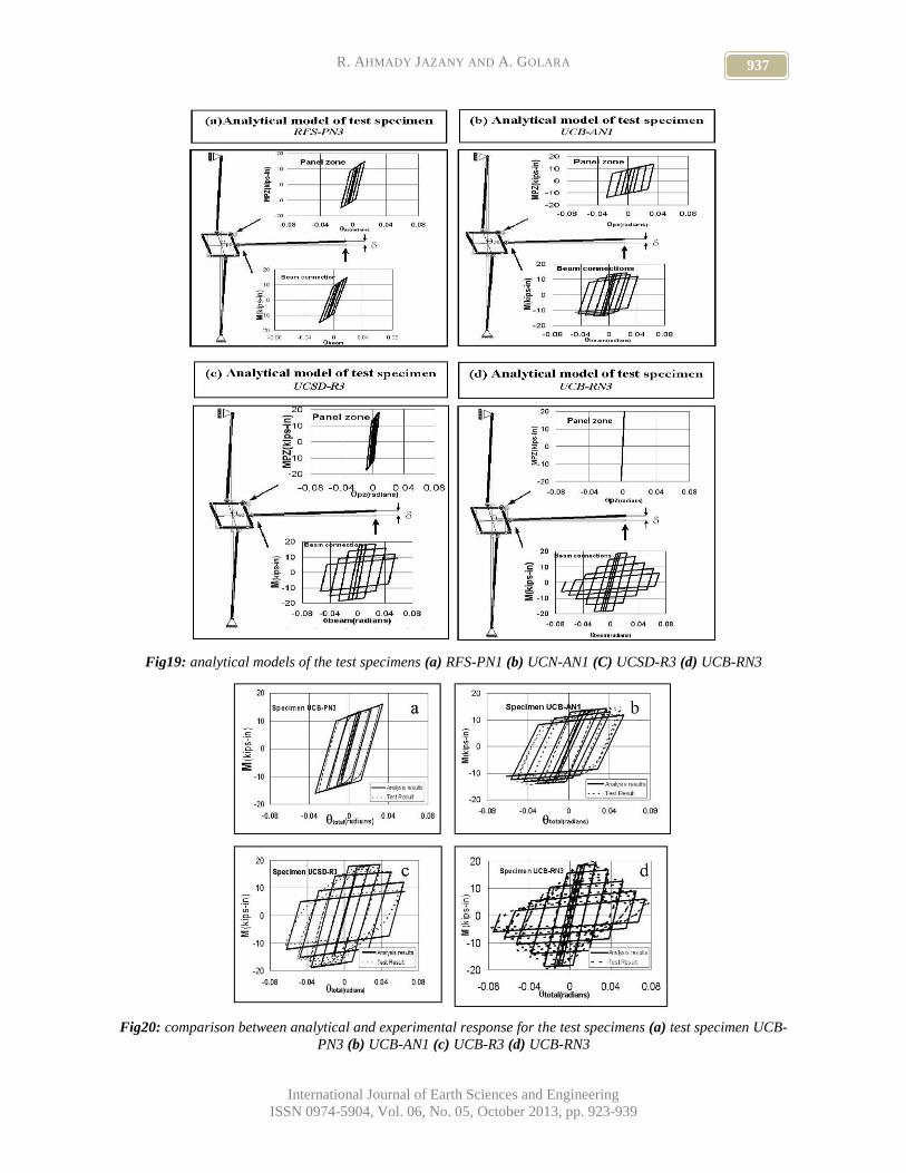
The proposed PZ models of this study were validated by
cyclic behavior of reference test model. In order to
perform analytical modeling of PZ, Drain-2DX
Analytical modeling software [40] was used. The spring
specifications used in the Drain-2DX were provided by
the average values for each connection type (regression
line) as shown in Figs 11, 13, 16 and 17. Fig.19 shows
cyclic responses generated by analytical model
including applied moment versus beam rotation and
panel zone rotation with respect to connection type.
Based on this Figure panel zone of the test specimen
with cover plate connection (UCB-AN1) has more PZ
rotation compared to the corresponding value of
analytical model with test specimens WUF-B
connection (RFS-PN3) and PZ rotation of analytical
model of test specimen with one sided haunch
connection (USCD-R3) provides minimum plastic
rotation (See Fig 19).
However, PZ of Analytical models of test specimen
with double-sided haunches remain in linear phase (Fig.
19).Fig 20 shows comparison between analytical and
experimental response for the test specimens of UCB-
PN3, UCB-AN1, UCB-R3 and UCB-RN3 with different
connection types. Based on Fig 20, cyclic response of
analytical model (Figure 19) agreed well with the cyclic
response of the corresponding response experiments. It
means that proposed model of PZ, which its rotation is a
part of total rotation provide good estimation for PZ
deformation. FEMA 273 [32] suggests a constant
partial ductility factor ( ) for PZ, without
consideration connection type effects on PZ seismic
behavior. Krawinkler et al. [3] showed that the value of
four times of PZ elastic distortion(y4 ) as stable PZ
plastic distortion will be promising value and it can
keep the connection within a safe margin whereas the
results of this study showed that this values strongly
depends on the connection type and shear ratio
(Vy/VPZMy). Considering backbone curve of PZ as
shown in Figs 4 to 7; elastic and plastic rotation of PZ
depend on the connection type ,i.e. cover plate ,flange
plate and haunch connection system, shear ratio
(Vy/VPZMy) and also number of continuity plate on the
panel zone.
937 R. AHMADY JAZANY AND A. GOLARA
International Journal of Earth Sciences and Engineering
ISSN 0974-5904, Vol. 06, No. 05, October 2013, pp. 923-939
Fig19: analytical models of the test specimens (a) RFS-PN1 (b) UCN-AN1 (C) UCSD-R3 (d) UCB-RN3
Fig20: comparison between analytical and experimental response for the test specimens (a) test specimen UCB-
PN3 (b) UCB-AN1 (c) UCB-R3 (d) UCB-RN3
938 Modeling of PZ in accordance to the type of Connections in SMRF
International Journal of Earth Sciences and Engineering
ISSN 0974-5904, Vol. 06, No. 05, October 2013, pp. 923-939
8. Conclusion:
This study investigated on the PZ cyclic behavior
according to connection type. This study emphasized
that the type of connection besides shear ratio
(Vy/VPZMy) affects the PZ nonlinear behavior. The
following conclusions can be made:
1. Analytical results of this study showed that PZ
plastic rotation value was certainly affected by type
of connection; in other word, PZ of analytical
models of the test specimens with cover plate
provide more PZ plastic rotation rather than the
corresponding values of test specimen with WUF-B
connection and haunch connection system. The
above-mentioned values of PZ with WUF-B
connection provide more plastic rotation capacity
than the corresponding values for test specimens
with haunch system.
2. In the haunch connection system, PZ of test
specimen with one-sided haunch provide
insignificant plastic rotation capacity while for the
analytical model with two-sided haunch, PZ hardly
enter nonlinear phase and it behaves linearly. Also
for this connection type, slope of regression line is
less than others. The results of this study showed
that dependency of PZ plastic strain on shear ratio
Vy/VPZMy in this type of connection is less than
others, and presence of three or four continuity
plates respectively for one-sided haunch and two-
sided haunch, in front of haunch flange and beam
flange, reduces plastic rotation of PZ
3. 3- In the analytical models with cover plate
connection, as shown in Figs 19, analytical data
were scattered compared to other categories. Based
on analytical modeling of PZ derived by neural
network and finite element model, the cover plate
connections provide the minimum strength at least
equal to 1 Mp (full plastic moment). In the case of
analytical models with one-sided haunch, the
corresponding value at least reaches to similar
value compared to cover plate connection but the
maximum values reaches to 1.4 full plastic
moments.
4. The results of this study also showed that ductility
ratio of Panel zone, which was equal to 12y based
on FEMA 273[32] ( y is panel zone yielding shear
strain), is not a constant value. This value depends
on type of connection, for example in the case of
cover plate; ductility ratio is greater than the
corresponding value for analytical model of test
specimen with haunch connection system and
WUF-B connection.
5. The results of this research showed that the
proposed analytical modeling of the panel zone
result in total cyclic response of SMRF connections
with acceptable accuracy compared to the main
reference experimental responses and
corresponding analytical data generated by Finite
element modeling of this study.
9. Acknowledgments:
The authors would like to thank Dr. Ghobadi for his
invaluable comments to improve the manuscript and
Prof. D. Venkat Reddy Editor in chief of International
Journal of Earth Sciences and Engineering (IJEE) for
his kind cooperation for publication the article.
10. References:
[1] Naka, T., Kato, B., Watabe, M., and Nakato, M.
1969. “Research on the behaviour of steel beam-to-
column connections”. 4th World Conference of
Earthquake Engineering, Santiago, Chile.
[2] Fielding, D.J., and Huang, J.S. 1971. “Shear in steel
beam-to-column connections”. Welding Journal,
50(7): 313–326.
[3] Krawinkler, H., Bereto, V.V., and Popov, E.P.
1971. “Inelastic behaviour of steel beam to columns
subassemblagement”. EERC Report No. 71-7,
University of California, Berkeley.
[4] Bertero, V.V., Krawinkler, H., and Popov, E.P.
1973. “Further studies on seismic behaviour of steel
beam-to-column subassemblages”. EERC Report
No. 73-27, University of California, Berkeley.
[5] Becker, R. “Panel zone effect on the strength and
stiffness of steel rigid frames”. Engineering
Journal, AISC, 1975; 12(1): 19–29.
[6] Slutter, R. 1981. “Tests of panel Zone behavior in
beam column connections”. Report No.
200.81.403.1, Lehigh University, Bethlehem, Pa.
[7] Popov, E.P., Amin, N.R., Louis, J.J.C., and
Stephen, R.M. 1985. “Cycle behavior of large beam
column assemblies”. Earthquake Spectra, 1(2).
[8] Popov, E.P. 1987. “Panel zone flexibility in seismic
moment joints”. Journal of Constructional Steel
Research, 8: 91–118.
[9] International Conference of Building Officials
(ICBO). “Uniform building code”. 1988 ed. ICBO,
Whittier, Calif.
[10] American Institute of Steel Construction (AISC).
Seismic provisions for structural steel buildings.
1997 American Institute of Steel Construction,
Chicago.
[11] Tsai, K.C., and Popov, E.P. 1988. “Steel beam-
column joints in seismic moment resisting frames”.
UCB/EERC Report No. 89/19, University of
California, Berkeley.
[12] Federal Emergency Management Agency (FEMA).
1997. Interim guideline. Advisory No.1,
939 R. AHMADY JAZANY AND A. GOLARA
International Journal of Earth Sciences and Engineering
ISSN 0974-5904, Vol. 06, No. 05, October 2013, pp. 923-939
supplement to FEMA-267. FEMA-267A/Report
SAC-96-03, SAC Joint Venture, Sacramento, Calif.
[13] Lee, C.H., Jeon, S.W., Kim, J.H., and Uang, C.H.
2005. “Effects of panel zone strength and beam
web connection method on seismic performance of
reduced beam section steel moment connections”.
Journal of Structural Engineering, 131(12): 1854–
1865.
[14] Dubina, D., Ciutina, A., and Stratan, A. 2001.
“Cyclic test of double sided beam-to-column
joints”. Journal of Structural Engineering, 127(2):
129–136.
[15] Ciutina, A.L., and Dubina, D. 2006. “Seismic
behaviour of steel beam to-column joints with
column web stiffening”. Steel and Composite
Structures, 6(6): 493–512.
[16] Federal Emergency Management Agency (FEMA).
2000a. State of the art report on connection
performance. FEMA-355D, prepared by the SAC
Joint Venture for FEMA, Washington, D.C.
[17] Jin, J., and El-Tawil, S. 2005. “Evaluation of
FEMA 350 seismic provisions for steel panel
zones”. Journal of Structural Engineering, 131(2):
250–258.
[18] Hosseini Hashemi B, Ahmady jazany R.2012.
“Study of connection detailing on SMRF seismic
behavior for unequal beam depths”. Journal of
constructional steel research (JCSR), 68 (1) 150–
164.
[19] Hosseini Hashemi B, Ahmady jazany R.2010.
“Experimental evaluation of cover plate and flange
plate steel moment resisting connections
considering unequal beam depths”. Journal of
seismology and earthquake engineering (JSEE)
12(3):88-102.
[20] Ahmady jazany R, Hosseini Hashemi B.2012.
“Effects of Detailing on Panel Zone Seismic
Behaviour in Special Moment Resisting Frames
with Unequal Beam Depths”. Canadian journal of
civil engineering (CJCE); 39(4):388-401.
[21] Ahmady Jazany R. “study of panel zone seismic
behavior in SMRF for unequal beam depths”. PhD.
Thesis, International institute of earthquake
engineering and seismology (IIEES) No. 90-3-06;
Nov 2011.
[22] Federal Emergency Management Agency (FEMA).
1996. “Experimental investigations of beam-
column sub-assemblages”. Report SAC-96-01, Part
1, SAC Joint Venture, Sacramento, Calif.
[23] Popov, E.P., Blondet, M. M. Stepamov, L. and
Stoja dinovic, B 1996 “Full-scale Steel Beam
Coloumn Connection Tests”, SAC 96-01 Part 2.
SACjoint Venture.
[24] Chi WM, Deierilein AR. “Fractures toughness
demands in welded beam –column moment
connections”. J Struct Engrg, ASCE 2000; 126(1).
[25] El-Tawil S. “Panel zone yielding in steel moment
connection” .Engrg J AISC 2000; 3qrt00:120.31.
[26] Popov, E.P, Amin, N.R.Louiej. j.c, and Stephen,
1985. “Cyclic behavior of Large Beam to Column
assemblies” Earthquake Spectra, 1 (2):203-238.
[27] Qi -Song, Uang Chia-Ming, Gross J. “Seismic
rehabilitation design of steel moment connection
with welded haunch”. Journal of Structural
Engineering 2000; 126: 69–78.
[28] ANSYS. User's Manual, Version 5.4. 201. Johnson
Road, Houston: ANSYS Inc.; 1998.
[29] ATC 24. Guidelines for cyclic seismic testing of
components of steel structures. Applied
Technology Council; 1992.
[30] AWS. Structural Welding Code — Steel. Miami
(FL): American Welding Society; 2002.
[31] Ghaboussi, J, & wu, X.soft “computing with neural
network for engineering application”. Fundamental
issues and adaptive approaches, structural
engineering and mechanics 1998, 6(8), 955-969.
[32] FEMA. “Provion for rehabilitation of exsiting
structutes”. Federal management agency, FEMA
273.2002.
[33] Whan Han S, Kwon Gun Up, Moon K.H. “Cyclic
behavior of post Northridge WUF-B connections”
Journal of constructional steel research 2007; 12
(5): 365-374.
[34] Noel, s Yang, c.-m. “Cyclic Testing of Steel
Moment connection s for the for the San Francisco
civic center” Report NO .TR-96/07 ,Division of
structural engineering ,University of California, San
diego,1996
[35] Chia-Ming Uang, Duane Bondad, Cheol-Ho Lee.
“Cyclic performance of haunch repaired steel
moment connections”. Experimental testing and
analytical modeling Engineering Structures 1998;
20:552–61.
[36] Civjan SA, Engelhardt MD, Gross JA. “Retrofit of
pre-Northridge moment-resisting connections”.
Journal of Structural Engineering 2000; 126:445–
52.
[37] Schinder, S.P. and Amidi A. “Seismic Behavior of
Steel Frames with Deformable Panel Zone”.
Journal of Structural Engineering ASCE 1998:124
(1):35-42
[38] Yang, popov E.”Design of Steel MRF before and
After 1994 Northridge Earthquake”. Proceedings;
International Conference on Advance in Steel
Structures,Hong Kong, 1996.
[39] Gupta, Krawinkler h. “Seismic demands for
performance evaluation of steel moment resisting
frames structures”. Blume Engineering Research
Center,Rep No132 Dept . stanford university;1999.
[40] Parakash v, Powell GH, DRAIN-2DX Base
Program Description and user Guide ver1.10.
Related Documents