Pergamon 0956-7151(95)00345-2 Acta mater. Vol. 44, No. 6, 2465-2478, 1996 pp. Elsevier Science Ltd Copyright 0 1996 Acta Metallurgica Inc. Printed in Great Britain. All rights reserved 1359-6454/96 $15.00 + 0.00 MODELING OF METAL MATRIX COMPOSITES BY A SELF-CONSISTENT EMBEDDED CELL MODEL M. DONG and S. SCHMAUDER Staatliche Materialpriifungsanstalt (MPA), University of Stuttgart, Pfaffenwaldring 32, D-70569 Stuttgart, Germany (Received 26 July 199s) Abstract-The limit flow stresses for transverse loading of metal matrix composites reinforced with continuous fibers and for uniaxial loading of spherical particle reinforced metal matrix composites are investigated by recently developed embedded cell models in conjunction with the finite element method. A fiber of circular cross section or a spherical particle is surrounded by a metal matrix, which is again embedded in the composite material with the mechanical behavior to be determined iteratively in a self-consistent manner. Stress-strain curves have been calculated for a number of metal matrix composites with the embedded cell method and compared with literature data of a particle reinforced Ag-58vol.%Ni composite and for a transversely loaded uniaxially fiber reinforced Al46vol.%B composite. Good agreement has been obtained between experiment and calculation and the embedded cell model is thus found to represent well metal matrix composites with randomly arranged inclusions. Systematic studies of the mechanical behavior of fiber and particle reinforced composites with plane strain and axisymmetric embedded cell models are carried out to determine the influence of fiber or particle volume fraction and matrix strain-hardening ability on composite strengthening levels. Results for random inclusion arrangements obtained with self-consistent embedded cell models are compared with strength- ening levels for regular inclusion arrangements from conventional unit cell models. It is found that with increasing inclusion volume fractions there exist pronounced differences in composite strengthening between all models. Finally, closed-form expressions are derived to predict composite strengthening levels for regular and random fiber or particle arrangements as a function of matrix hardening and particle volume fraction. The impact of the results on effectively designing technically relevant metal matrix composites reinforced by randomly arranged strong inclusions is emphasized. INTRODUCTION Metal matrix composites (MMCs) with strong inclusions are a new class of materials which, due to high strength and light weight, are potentially valu- able in aerospace and transportation applications [ 11. MMCs are defined as ductile matrix materials reinforced by brittle fibers or particles. Under exter- nal loading conditions the overall response of MMCs is elastic-plastic. MMCs are frequently reinforced by continuous fibers which are aligned in order to make use of the high axial fiber strength. However, the mechanical behavior of these composites under trans- verse loading is well behind their axial performance [2-71. On the other hand, it is well known, both from experiment and calculations [8] that details of trans- verse strengthening in uniaxially fiber reinforced MMCs are a strong function of fiber arrangement. To derive the mechanical behavior of MMCs, a micromechanical approach is usually employed using cell models, representing regular inclusion arrange- ments. As regular fiber spacings are difficult to achieve in practice, most of the present fiber reinforced MMCs contain aligned but randomly arranged continuous fibers. Thus, the accurate mod- eling of the mechanical behavior of actual MMCs is very complicated in practice even if the fibers are aligned. Initially, the transverse mechanical behavior of a unidirectionally continuous fiber-reinforced com- posite (Al-B) with fibers of circular cross section was studied by Adams [9] adopting finite element cell models under plane strain conditions: a simple geo- metrical cell composed of matrix and inclusion ma- terial is repeated by appropriate boundary conditions to represent a composite with a periodic microstruc- ture. Good agreement was achieved between calcu- lated and experimental stress-strain curves for a rectangular fiber arrangement. The influence of different regular fiber arrangements on the strength of transversely loaded boron fiber reinforced Al was analyzed in Refs [2, 5,7]. It was found that the same square arrangement of fibers represents two extremes of strengthening: high strength levels are achieved if the composite is loaded in a 0” direction to nearest neighbors while the 45” loading direction is found to be very weak for the same fiber arrangement. .4 regular hexagonal fiber arrangement lies somewhere 2465

Welcome message from author
This document is posted to help you gain knowledge. Please leave a comment to let me know what you think about it! Share it to your friends and learn new things together.
Transcript
Pergamon 0956-7151(95)00345-2
Acta mater. Vol. 44, No. 6, 2465-2478, 1996 pp. Elsevier Science Ltd
Copyright 0 1996 Acta Metallurgica Inc. Printed in Great Britain. All rights reserved
1359-6454/96 $15.00 + 0.00
MODELING OF METAL MATRIX COMPOSITES BY A SELF-CONSISTENT EMBEDDED CELL MODEL
M. DONG and S. SCHMAUDER Staatliche Materialpriifungsanstalt (MPA), University of Stuttgart, Pfaffenwaldring 32, D-70569
Stuttgart, Germany
(Received 26 July 199s)
Abstract-The limit flow stresses for transverse loading of metal matrix composites reinforced with continuous fibers and for uniaxial loading of spherical particle reinforced metal matrix composites are investigated by recently developed embedded cell models in conjunction with the finite element method. A fiber of circular cross section or a spherical particle is surrounded by a metal matrix, which is again embedded in the composite material with the mechanical behavior to be determined iteratively in a self-consistent manner.
Stress-strain curves have been calculated for a number of metal matrix composites with the embedded cell method and compared with literature data of a particle reinforced Ag-58vol.%Ni composite and for a transversely loaded uniaxially fiber reinforced Al46vol.%B composite. Good agreement has been obtained between experiment and calculation and the embedded cell model is thus found to represent well metal matrix composites with randomly arranged inclusions.
Systematic studies of the mechanical behavior of fiber and particle reinforced composites with plane strain and axisymmetric embedded cell models are carried out to determine the influence of fiber or particle volume fraction and matrix strain-hardening ability on composite strengthening levels. Results for random inclusion arrangements obtained with self-consistent embedded cell models are compared with strength- ening levels for regular inclusion arrangements from conventional unit cell models. It is found that with increasing inclusion volume fractions there exist pronounced differences in composite strengthening between all models.
Finally, closed-form expressions are derived to predict composite strengthening levels for regular and random fiber or particle arrangements as a function of matrix hardening and particle volume fraction. The impact of the results on effectively designing technically relevant metal matrix composites reinforced by randomly arranged strong inclusions is emphasized.
INTRODUCTION
Metal matrix composites (MMCs) with strong inclusions are a new class of materials which, due to high strength and light weight, are potentially valu- able in aerospace and transportation applications [ 11.
MMCs are defined as ductile matrix materials reinforced by brittle fibers or particles. Under exter- nal loading conditions the overall response of MMCs is elastic-plastic. MMCs are frequently reinforced by continuous fibers which are aligned in order to make use of the high axial fiber strength. However, the mechanical behavior of these composites under trans- verse loading is well behind their axial performance [2-71. On the other hand, it is well known, both from experiment and calculations [8] that details of trans- verse strengthening in uniaxially fiber reinforced MMCs are a strong function of fiber arrangement. To derive the mechanical behavior of MMCs, a micromechanical approach is usually employed using cell models, representing regular inclusion arrange- ments. As regular fiber spacings are difficult to achieve in practice, most of the present fiber reinforced MMCs contain aligned but randomly
arranged continuous fibers. Thus, the accurate mod- eling of the mechanical behavior of actual MMCs is very complicated in practice even if the fibers are aligned.
Initially, the transverse mechanical behavior of a unidirectionally continuous fiber-reinforced com- posite (Al-B) with fibers of circular cross section was studied by Adams [9] adopting finite element cell models under plane strain conditions: a simple geo- metrical cell composed of matrix and inclusion ma- terial is repeated by appropriate boundary conditions to represent a composite with a periodic microstruc- ture. Good agreement was achieved between calcu- lated and experimental stress-strain curves for a rectangular fiber arrangement. The influence of different regular fiber arrangements on the strength of transversely loaded boron fiber reinforced Al was analyzed in Refs [2, 5,7]. It was found that the same square arrangement of fibers represents two extremes of strengthening: high strength levels are achieved if the composite is loaded in a 0” direction to nearest neighbors while the 45” loading direction is found to be very weak for the same fiber arrangement. .4 regular hexagonal fiber arrangement lies somewhere
2465
2466 DONG and SCHMAUDER: MODELING METAL. MATRIX COMPOSITES
between these limits [2, 5, 7, IO, 111. The transverse mechanical behavior of a realistic fiber reinforced composite containing about 30 randomly arranged fibers was found to be best described but significantly underestimated by the hexagonal fiber model [5]. One reason for the superiority of the hexagonal over the square arrangement in describing random fiber arrangements is due to the fact that the elastic stress invariants of the square arrangement agree only to first order with the invariants of the transversely isotropic material while the hexagonal arrangement agrees up to the second order [lo]. Dietrich [6] found a transversely isotropic square fiber reinforced Ag-Ni composite material using fibers of different diameters. A systematic study in which the fiber volume fraction and the fiber arrangement effects have been investi- gated was founded into a simple model in Ref. [ll].
The influence of fiber shape and clustering was numerically examined in some detail by Llorca et al. [12], Dietrich [6] and Sautter [13]. It was observed that facetted fiber cross sections lead to higher strengths compared to circular cross sections except for such fibers which possess predominantly facets oriented at 45” with respect to the loading axis in close agreement with findings in particle reinforced MMCs [14]. Thus, hindering of shear band formation within the matrix was found to be responsible for strengthening with respect to fiber arrangement and fiber shape [12]. In Refs [8, 11, 15, 161 local distri- butions of stresses and strains within the microstruc- ture have also been identified to be strongly influenced by the arrangement of fibers. However, no agreement was found between the mechanical behav- ior of composites based on cell models with differ- ently arranged fibers and experiments with randomly arranged fibers loaded in the transverse direction.
The overall mechanical behavior of a particle reinforced composite was studied with axisymmetric finite element cell models by Bao et al. [17] to represent a uniform particle distribution within an elastic-plastic matrix. Tvergaard [ 181 introduced a modified cylindrical unit cell containing one half of a single fiber to model the axial performance of a periodic square arrangement of staggered short fibers. Horn [19] and Weissenbek [20] used three- dimensional finite elements to model different regular arrangements of short fibers and spherical as well as cylindrical particles with relatively small volume frac- tions (f< 0.2). It was generally found that the arrangement of fibers strongly influences the different overall behavior of the composites. When short fibers are arranged in a side-by-side manner, they constrain the plastic flow in the matrix and the computed stress-strain response of the composite in the fiber direction is stiffer than observed in experiments. If the fibers in the model are overlapping, strong plastic shearing can develop in the ligament between neigh- boring fibers and the predicted load carrying capacity of the composite is closer to the experimental measurements. In Ref. [21] the stress-strain curves
based on FE-numerical solutions of axisymmetric unit cell models of MMCs are given in a closed form as a function of the most important control par- ameters. namely. volume fraction. aspect ratio and shape (cylindrical or spherical) of the reinforcement as well as the matrix hardening parameter.
One reason for the discrepancy between exper- iments and calculations based on simple cell models in the case of particle, whisker and fiber reinforced metals is believed to be the un-natural constraint governing the matrix material between inclusion and simulation cell border [5. IS. 17-19,222241 resulting in an unrealistic strength increase. The influence of thermal residual stresses in fiber reinforced MMCs under transverse tension was studied in Ref. [7] and found to lead to significant strengthening elevations in contrast to findings in particulate reinforced MMCs where strength reductions were calculated
1251. A limited study on the overall limit flow stress for
composites with randomly oriented disk- or needle- shaped particles arranged in a packet-like mor- phology is reported by Bao et al. [17]. In Refs [26,27] a modified Oldroyd model has been proposed to investigate analytically-numerically the overall behavior of MMCs with randomly arranged brittle particles. Duva [28] introduced an analytical mode1 to represent a random distribution of non-interacting rigid spherical particles perfectly bonded in a power law matrix. The Duva model is a self-consistent model and should be valid particularly in the dilute regime of volume fractions, ,f‘ < 0.2.
In this work, cell models are applied to simulate, for a number of relevant parameters, the transverse behavior of MMCs containing fibers in a regular square or hexagonal arrangement as well as the mechanical behavior of MMCs containing particles in a regular arrangement. MMCs with randomly arranged inclusions are modeled by a recently intro- duced self-consistent procedure with embedded cell models. This method of surrounding a simulation cell by additional “equivalent composite material” was introduced in Ref. [6] for structures which are period- ical in the loading direction and was recently extended to non-periodic two-dimensional [29-3 l] and three-dimensional composites [ 13,271. The method is known to remove the above described unrealistic constraints of cell models. An initial com- parison of two- and three-dimensional embedded cell models in the case of perfectly-plastic matrix material depicts elevated strength levels for the three-dimen- sional case [27]-similar to composites with regularly arranged fibers [ 111.
The purpose of the present paper is to investigate the mechanical behavior of MMCs reinforced with regular or random arranged continuous fibers under transverse loading, as well as the mechanical behavior of MMCs reinforced with regular or ran- dom arranged particles under uniaxial loading, and to systematically study composite strengthening as a

DONG and SCHMAUDER: MODELING METAL MATRIX COMPOSITES 2461
function of inclusion volume fraction and matrix hardening ability. The finite element method (FEM) is employed within the framework of continuum mechanics to carry out the calculations.
MODEL FORMULATION
A continuum mechanics approach is used to model the composite behavior. The inclusion behaves elasti- cally in all cases considered here and its stiffness is much higher than that of the matrix, so that the inclusion can be regarded as being rigid. In addition, the continuous fibers of circular cross section and spherical particles are assumed to be well bonded to the matrix so that debonding or sliding at the inclusion-matrix interface is not permitted. The uni- axial matrix stress-strain behavior is described by a Ramberg-Osgood type of power law
O=EE E<E
& ” c.r=cTo - [I E > &o
co where ~7 and E are the uniaxial stress and strain of the matrix, respectively, u. is the tensile flow stress, the matrix yield strain is given as ,so = ao/& E is Young’s modulus, and N = l/n is the strain hardening expo- nent. Thus, N = 0 corresponds to a non-hardening matrix.
J, flow theory of plasticity with isotropic hardening is employed with a von Mises yield criterion to characterize the rate-independent matrix material. The von Mises equivalent stress and strain are given as:
where sii = dii - crkk 13, eii = Ed - .akk/3 and v is Pois- son’s ratio. In the analytical approach, the metal matrix is considered incompressible, so Poisson’s ratio of the matrix will become 0.5 after reaching the yield stress. However, in reality Poisson’s ratio of the composite remains below 0.5 as the matrix starts yielding. It changes from the elastic value v to the limit value 0.5 with increasing yielding zone in the matrix.
The Ramberg-Osgood type of matrix power law hardening is assumed to be valid for the matrix described in terms of von Mises equivalent stress and strain
with the following relations between stress and strain under uniaxial loading and von Mises equivalent stress and strain.
(a) In the case of a two-dimensional (2D) plane strain condition for continuous fiber reinforced com-
posites (d/2 x 0.866, 2/a z 1.1547)
a G=-c?”
2 with fi o. = - oVo
2
(4)
(b) In the case of three-dimensional (3D) axisym- metrical condition for particle reinforced composites
u = 0” with cro = oVO
E = a, with a0 = aVO. (5)
The global mechanical response of the composite under external loading is characterized by the overall stress 5 as a function of the overall strain g. More- over, to describe the results in a consistent way, the reference axial yield stress o. and yield strain a, of the matrix, as defined in equation (4) for the 2D case and in equation (5) for the 3D case, will be taken to normalize the overall stress and strain of the com- posite, respectively.
Following Bao et al. [ 171 the composite containing hard inclusions will necessarily harden with the same strain hardening exponent, N, as the matrix for the case of hard inclusions, when strains are in the regime of fully developed plastic flow. At sufficiently large strains the composite behavior is then described by
r zlN
where CN is called the asymptotic reference stress of the composite which can be determined by normaliz- ing the composite stress by the stress in the matrix at the same overall strain E [equation (l)], as indicated in Fig. 1:
6 (8) a,=a, 7
[ 1 O(E) for f>>co. (7)
For a matrix of strain hardening capability N, the limit value 6,/a, is defined as the composite strength- ening level, which is an important value to describe the mechanical behavior of composites and which
Composite with a Strain-hardening Matrix (N>O.O)
Inclusion
Matrix ~J(E)/~(E)
Normalized Strain E/E0
Fig. 1. Composite strengthening.
246X DONG and SCHMALJDER: MODELING METAL MATRIX COMPOSITES
depends only on fiber and particle arrangement, inclusion volume fraction and matrix strain-harden- ing exponent.
UNIT CELL MODELS
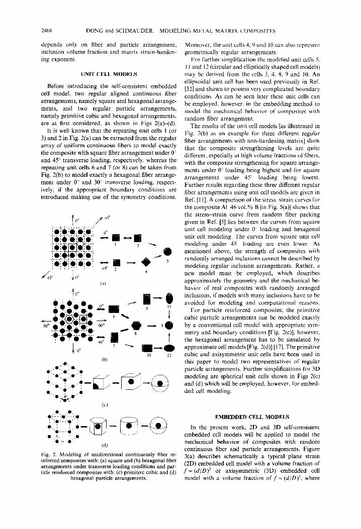
Before introducing the self-consistent embedded cell model, two regular aligned continuous fiber arrangements, namely square and hexagonal arrange- ments, and two regular particle arrangements, namely primitive cubic and hexagonal arrangements, are at first considered, as shown in Figs 2(a)<d).
It is well known that the repeating unit cells 1 (or 3) and 2 in Fig. 2(a) can be extracted from the regular array of uniform continuous fibers to model exactly the composite with square fiber arrangement under 0” and 45” transverse loading, respectively, whereas the repeating unit cells 6 and 7 (or 8) can be taken from Fig. 2(b) to model exactly a hexagonal fiber arrange- ment under 0” and 30” transverse loading, respect- ively, if the appropriate boundary conditions are introduced making use of the symmetry conditions.
Fig. 2. Modeling of unidirectional continuously fiber re- inforced composites with: (a) square and (b) hexagonal fiber arrangements under transverse loading conditions and par- ticle reinforced composites with: (c) primitive cubic and (d)
hexagonal particle arrangements.
Moreover, the unit cells 4, 9 and 10 can also represent geometrically regular arrangements.
For further simplification the modified unit cells 5. 1 I and 12 (circular and elliptically shaped cell models) may be derived from the cells 3. 4. 8, 9 and IO. An ellipsoidal unit cell has been used previously in Ref. [32] and shown to possess very complicated boundary conditions. As can be seen later these unit cells can be employed, however, in the embedding method to model the mechanical behavior of composites with random fiber arrangement.
The results of the unit cell models [as illustrated in Fig. 7(b) as an example for three different regular fiber arrangements with non-hardening matrix] show that the composite strengthening levels are quite different, especially at high volume fractions of fibers, with the composite strengthening for square arrange- ments under 0” loading being highest and for square arrangements under 45” loading being lowest. Further results regarding these three different regular fiber arrangements using unit cell models are given in Ref. [l 11. A comparison of the stress-strain curves for the composite Al46 vol.% B [in Fig. 5(a)] shows that the stress-strain curve from random fiber packing given in Ref. [5] lies between the curves from square unit cell modeling under 0. loading and hexagonal unit cell modeling. The curves from square unit cell modeling under 45. loading are even lower. As mentioned above, the strength of composites with randomly arranged inclusions cannot be described by modeling regular inclusion arrangements. Rather, a new model must be employed, which describes approximately the geometry and the mechanical be- havior of real composites with randomly arranged inclusions, if models with many inclusions have to be avoided for modeling and computational reasons.
For particle reinforced composites, the primitive cubic particle arrangements can be modeled exactly by a conventional cell model with appropriate sym- metry and boundary conditions [Fig. 2(c)], however. the hexagonal arrangement has to be simulated by approximate cell models [Fig. 2(d)] [ 171. The primitive cubic and axisymmetric unit cells have been used in this paper to model two representatives of regular particle arrangements. Further simplifications for 3D modeling are spherical unit cells shown in Figs 2(c) and (d) which will be employed, however, for embed- ded cell modeling.
EMBEDDED CELL MODELS
In the present work, 2D and 3D self-consistent embedded cell models will be applied to model the mechanical behavior of composites with random continuous fiber and particle arrangements. Figure 3(a) describes schematically a typical plane strain (2D) embedded cell model with a volume fraction of f= (d/O)* or axisymmetric (3D) embedded cell model with a volume fraction of ,f= (d/D)3, where

DONG and SCHMAUDER: MODELING METAL MATRIX COMPOSITES 2469
Embedding Composite
d
Embedded Inclusion/Matrix Cell
L (L>>D)
(a)
uy (Displacement) 4
Matrix Inclusion
ft Symmetry line
Interface Cell boundary (b)
Under axial displacement loading at the external boundary of the embedding composite (Fig. 3) the overall response of the inner embedded cell can be obtained by averaging the stresses and strains in the embedded cell or alternatively the reaction forces and displacements at the boundary between the embed- ded cell and the surrounding volume.
Fig. 3. (a) Embedded cell model and (b) finite element mesh The embedding method is a self-consistent pro- for an embedded cell model. cedure, which requires several iterations as shown in
instead of using fixed or symmetry boundary con- ditions around the fiber-matrix or particle-matrix cell, the inclusion-matrix cell is rather embedded in an equivalent composite material with the mechanical behavior to be determined iteratively in a self-con- sistent manner. If the dimension of the embedding composite is sufficiently large compared with that of the embedded cell, e.g. L/D = 5 as used in this paper, the external geometry boundary conditions intro- duced around the embedding composite are almost without influence on the composite behavior of the inner embedded cell. Indeed, there exists no difference in the calculated results whether the vertical surfaces are kept unconstrained or remain straight during uniaxial loading.
To investigate the influence of the geometrical shape of the matrix phase on the overall behavior of the composite, different shapes of cross section of the embedded cell were chosen with a circular shaped continuous fiber surrounded by a circular, square, elliptical or rectangular shaped metal matrix (Fig. 6). A typical FE mesh and corresponding symmetry and boundary conditions are given in Fig. 3(b), where a circular fiber or a spherical particle is surrounded by a circular (for 2D) or spherical (for 3D) shaped metal matrix, which is again embedded in the compo- site material with the mechanical behavior to be determined.
ITERATIVE MODELING PROCEDURE
N=0.3, f=OS, (2D)
Iteration
5:
JI3
c 4 5
0.0 20.0 40.0 60.0 80.0 Normalized Equivalent Strain E” /Q,
Fig. 4. Iterative modeling procedure: stress-strain curves for different iteration steps.
2470 DONG and SCHMAUDER: MODELING METAL MATRIX COMPOSITES
Fig. 4. An initially assumed stress-strain curve (iter- ation 0 in Fig. 4) is first assigned to the embedding composite, in order to perform the first iteration step. An improved stress-strain curve of the composite (iteration 1) will be obtained by analyzing the average mechanical response of the embedded cell. This pro- cedure is repeated until the calculated stress-strain curve from the embedded cell is almost identical to that from the previous iteration. The convergence of the iteration occurs typically at the fifth iteration step, as illustrated in Fig. 4.
It has been found from systematic studies that convergence of the iteration to the final stress-strain curve of the composite is independent of the initial
mechanical behavior of the embedding composite (iteration 0). From an arbitrary initial stress-strain curve of the embedding composite the required com- posite response can be reached after 4-5 iterations for all cases.
The LARSTRAN finite element program [33] was employed using X-noded plane strain elements (for 2D) as well as axisymmetric biquadrilateral elements (for 3D) generated with the help of the pre- and postprocessing program PATRAN [34]. A DEC- Alpha work station 3000/3OOL was used to carry out the calculations, which typically took 30-50 min to obtain a stress-strain curve with 100-150 loading steps in one iteration loop
I
I Square Unit Cell 0”
-
* Brockenbrough et al., (1991)
0.4 0.6 Strain (%)
(a)
Ni (Inclusion),
0.0 L 0.00 0.10 0.20
Strain
(b)
Embedding Composite
Embedded Fib&?vla.tix Cell
Embedded Cell Model
Embedding Composite
t Embedded Particle/Matrix Cell
Embedded Cell Model
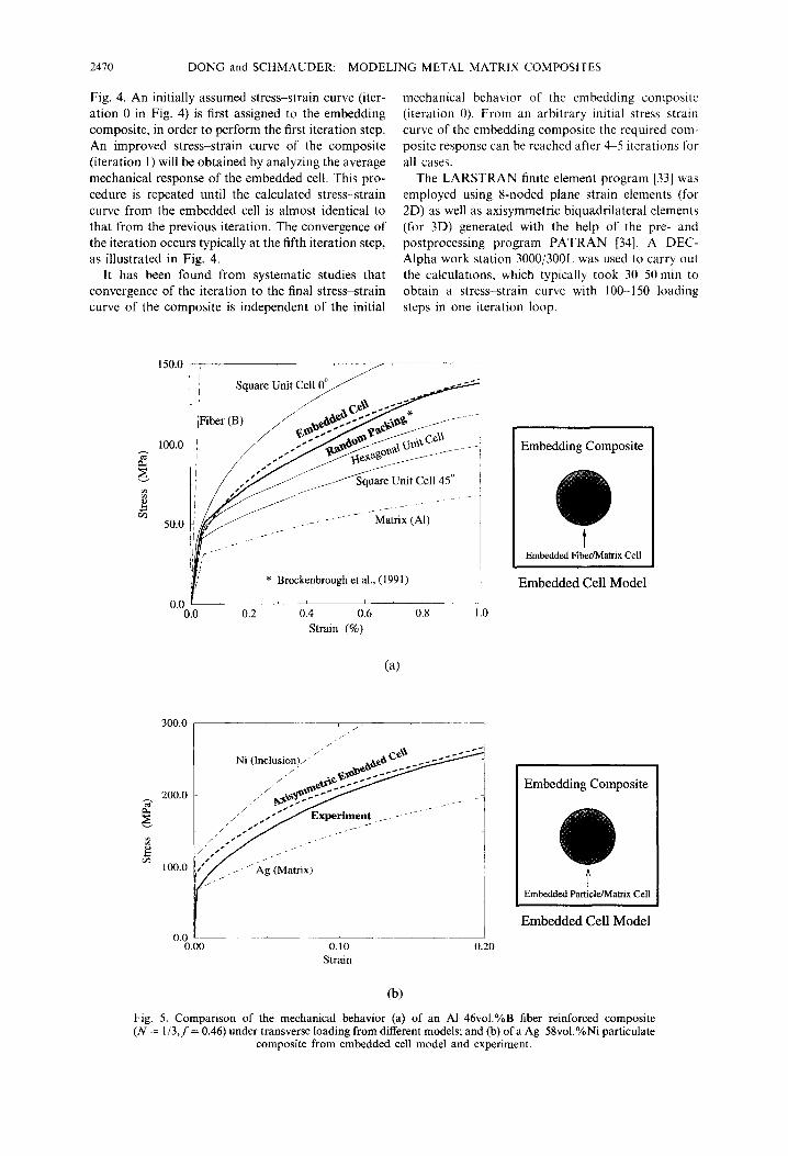
Fig. 5. Comparison of the mechanical behavior (a) of an A146vol.%B fiber reinforced composite (N = l/3, f = 0.46) under transverse loading from different models; and (b) of a Agd8vol.%Ni particulate
composite from embedded ceil model and experiment.

DONG and SCHMAUDER: MODELING METAL MATRIX COMPOSITES 2471
COMPARISON WITH EXPERIMENTS
An example of the composite Al46vol.%B with random fiber packing taken from Ref. [5] has been selected to verify the embedded cell model. This MMC is a 6061-O aluminum alloy reinforced with unidirectional cylindrical boron fibers of 46% volume fraction. The room temperature elastic properties of the fibers are Young’s modulus, EcB) = 410 GPa, and Poisson’s ratio, vcB) = 0.2. The experimentally deter- mined mechanical properties of the 6061-O alumi- num matrix are: Young’s modulus, EC*‘) = 69 GPa, Poisson’s ratio, v(*‘) = 0.33, 0.2% offset tensile yield strength, o0 = 43 MPa, and strain-hardening exponent, N = l/n = l/3.
Figure 5(a) shows a comparison of the stress-strain curves of the composite Al-46 vol.% B under trans- verse loading from simulations of a real microstruc- ture together with results from different cell models. The stress-strain curve from the embedded cell model employed in this paper shows good agreement with that from the calculated random fiber packing in the elastic and plastic regime, which lies between the curves from square unit cell modeling under 0” loading and hexagonal unit cell modeling.
Furthermore, the stress-strain curve from another experiment [27] on the composite Ag-58 vol.% Ni with random particle arrangement (Young’s modu- lus, EcNi) = 199.5 GPa, EcAg) = 82.7 GPa, Poisson’s ratio, vcN1) = 0.312, v(*g) = 0.367, and yield strength, .bN” = 193 MPa, ebAg) = 64 MPa) has been compared in Fig. 5(b) with that from the self-consistent embed- ded cell model. Good agreement in the regime of plastic response is obtained, although the Ni-particles in the experiment were not perfectly spherical.
These results indicate that the embedded cell model can be used to successfully simulate composites with random inclusion arrangements and to predict the elastic-plastic composite behavior.
GEOMETRICAL SHAPE OF EMBEDDED CELL
As mentioned above, different shapes of cross section of the embedded cell model with a circular shaped fiber, as shown in Fig. 6(a), are also taken into account to investigate the influence of the geometrical shape of the embedded cells on the overall behavior of the composite. The stress-strain curves of all embedded cell models with different geometrical shapes are plotted in Fig. 6(b). With an exception of the square45” embedded cell model the stress-strain curves are very close for all embedded cell shapes, namely, square&l”, circular, rectangularq”, rec- tangular-90”, elliptic-O” and elliptic-90”.
From the calculated results of the embedded cell models localized flows have been found around the hard fiber with preferred yielding at 45”. Because of the special geometry of the square45” embedded cell model with the cell boundary parallel to the preferred yielding at 45”, the overall stresses of the composite
with such a geometrical cell shape are therefore reduced, such that a relative lower stress-strain curve has been obtained from the modeling.
The almost identical responses of all other embed- ded cell models indicate that, besides the special shape of matrix with 45” cell boundaries, the pre- dicted mechanical behavior of fiber reinforced com- posites under transverse loading is independent of the modeling shape of the embedded composite cell. That allows us to employ any embedded cell shape to model the mechanical behavior of the composite with random fiber arrangement. In the following system- atic studies the circular shaped embedded cell model with circular cross section of rigid fiber will thus be taken to predict the general transverse mechanical behavior of the composite with random fiber arrange- ment. In the same way, a spherical shaped embedded cell model containing a spherical particle will be used to predict the axial mechanical behavior 01 composites with random particle arrangement.
SYSTEMATIC STUDIES WITH SELF-CONSISTENT EMBEDDED CELL MODELS
Composite strengthening is dependent on fiber and particle arrangement, inclusion volume fraction and the matrix strain-hardening exponent. The effect of fiber and particle arrangement is best demonstrated by considering different cell models. The effect of the
Square 0" Circular Square - 45’
u-u- Rectangular - 0’ Rectangular - 90’ Elliptic 0” Elliptic - 90”
(a)
r Al/46vol.%B
~ Ellipse 0”
Ellipse 90”
Rectangular 0”
Rectangular 90”
2.0 3.0 Strain (%)
(b)
Fig. 6. Embedded cell models: influence of (a) different matrix shapes on (b) stress-strain curves for an
A146vol.%B (N = l/3, f = 0.46) composite.

2472 DONG and SCHMAUDER: MODELING METAL MATRIX COMPOSITES
inclusion volume fraction has been taken into ac- count by applying different ratios of the circular (2D) and spherical (3D) matrix and the inclusion in the embedded cell model. The effect of the matrix strain- hardening exponent has been investigated by chang- ing the parameter, N, of the material hardening law for the matrix in equation (1). Some results from the systematic studies with embedded cell models are given in Figs 7-10.
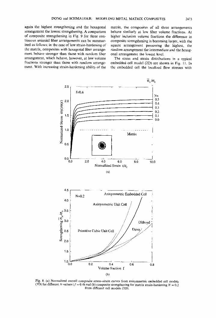
The influence of matrix strain-hardening is shown in Figs 7(a) and 8(a). The predicted transverse (2D) and axial (3D) overall stress-strain curves (normal- ized by yield stress and yield strain of the matrix, respectively) for the case of strain-hardening expo- nents between N = 0.0 and 0.5 are depicted in Fig. 7(a) (2D) for a fiber volume fraction off = 0.5 and in Fig. 8(a) (3D) for a particle volume fraction of f= 0.4. At sufficiently large strains (e.g. at E = lot,) the normalized overall stresses approach constant values, i.e. composite strengthening levels, as
Normalized Strain E/q
(a)
N=O.O
Square Unit Cell 0” 1
II e 0
ll Embedded Cell
,,.
00 0.2 0.4 0.6 0.8
Volume fraction f
:I1
1.0
(b)
Fig. 7. (a) Normalized stress-strain curves from embedded cell models (2D) for different N-values (f = 0.5) and (b) composite strengthening from different cell models (2D,
N = 0).
illustrated on the right-hand side of Figs 7(b) and 8(b) for E = lOa,. The strength of the composite is seen to increase with N and similar trends of nearly linear increase with N are found for all particle volume fractions, f’ [Figs 8(a) and IO].
The dependence of composite strengthening on inclusion volume fraction obtained by the self-con- sistent embedded cell modeling is shown in Fig. 7(b) for a non-hardening matrix with continuous fiber reinforcement and in Fig. 8(b) for a strain-hardening matrix (N = 0.2) with particle reinforcement. For comparison, the corresponding values of composite strengthening for regular fiber and particle arrange- ments taken from unit cell modeling and from two approximate models, namely Duva’s model [28] and the modified Oldroyd model [26,27] are also drawn as a function of fiber and particle volume fraction in these figures, respectively. A detailed discussion of this comparison is given in Ref. [27].
Duva’s model is a self-consistent model and valid particularly in the dilute regime, ,f’ < 0.2. Composite strengthening by the Duva model is given as
Composite strengthening levels of the modified Oldroyd model are taken from Ref. [27].
A summary of the dependence of composite strengthening on inclusion volume fraction and matrix strain-hardening for randomly arranged continuous fibers and particles is depicted in Figs 9 and 10(a) for matrix strain-hardening exponents N = 0.0-0.5, and compared with predictions from 2D and 3D unit cell models. In addition, a comparison with predictions from Duva’s model and the modified Oldroyd model for the case of particle reinforced composites is shown in Fig. 10(b).
For continuous fiber reinforced composites with a non-hardening matrix the hexagonal arrangement provides slightly higher transverse composite strengthening over the square arrangement at volume fractions f < 0.5, whereas the random arrangement from the embedded cell mode1 supplies an intermedi- ate value between the two regular arrangements except at volume fraction 0.38 <f< 0.5 (Fig. 9). At volume fractions 0.38 <f < 0.5, the random arrange- ment from the embedded cell mode1 possesses the lowest composite strengthening level. On the con- trary, the composite strengthening of the square arrangement is higher than that of the hexagonal arrangement for volume fractions f > 0.4. For the composite with a small exponent of strain-hardening matrix, N < 0.2, similar relations among the three arrangements were found, with the cross points of any two curves being closer to f‘= 0 with increasing N. For composites with a higher strain-hardening exponent of the matrix, N > 0.2, the strengthening values are almost the same for the three arrangements considered at volume fractions off < 0.2. At volume fractions off > 0.2, the square arrangement provides
DONG and SCHMAUDER: MODELING METAL MATRIX COMPOSITES 2413
again the highest strengthening and the hexagonal arrangement the lowest strengthening. A comparison of composite strengthening in Fig. 9 for three con- tinuous uniaxial fiber arrangements can be summar- ized as follows: in the case of low strain-hardening of the matrix, composites with hexagonal fiber arrange- ment behave stronger than those with random fiber arrangement, which behave, however, at low volume fractions stronger than those with random arrange- ment. With increasing strain-hardening ability of the
matrix, the composites of all three arrangements behave similarly at low fiber volume fractions. At higher inclusion volume fractions the difference in composite strengthening is becoming larger, with the square arrangement possessing the highest, the random arrangement the intermediate and the hexag- onal arrangement the lowest level.
The stress and strain distributions in a typical embedded cell model (2D) are shown in Fig. 11, In
the embedded cell the localized flow stresses with
2.5
d 2.0
g
Ig z 1.5
g VI -0 w 1.0
2
g
z 0.5
0.0 (
4.5
4.0
0 3.5 J?
’ $3.0 .9
42.5
al
2 2.0
1.5
1.0 C I.0
f=O.4
I
Matrix
N= 0.5 0.4 0.3 0.2 0.1 0.0
4.0 6.0 Normalized Strain akO
(a)
8.0 10.0
N=0.2 Axisymmetric Embedded Cell
/
Axisymmetric Unit Cell
il ,/ / Oldroyd
Primitive Cubic Unit Cell
0.4 Volume fraction f
0.6
(b)
Fig. 8. (a) Normalized overall composite stress-strain curves from axisymmetric embedded cell models (3D) for different N-values (f = 0.4) and (b) composite strengthening for matrix strain-hardening N = 0.2
from different cell models (3D).

2474 DONG and SCHMAUDER: MODELING MEL-AL MATRIX COMPOSITES
-- Square Unit Cell - Embedded Cell
- Hexagonal Unit Cell
0.2 0.4 0.6 0.8 Volume fraction f
Fig. 9. Comparison of composite strengthening by continuously aligned fibers from different 2D cell models: embedded cell model, square and hexagonal unit cell model.
preferred yielding in the 45” direction are seen apparently around the hard fiber and extending into the embedding composite in the vicinity of the embedded cell. It characterizes the local response of the composite under transverse loading. How- ever, the stresses and strains are homogeneously distributed in the embedding composite far from the embedded cell. This represents the overall behav- ior of the corresponding composite. In the case of random fiber arrangement, the situation around every single fiber is, of course, more complicated. However, the real situation can be considered in average as a fiber-matrix cell surrounded by corresponding equivalent composite material, which represents the average overall composite behavior.
From comparisons for particle reinforced com- posites in Figs 10(a) and (b) it can be seen that the composite strengthening levels from the primitive cubic, the axisymmetric unit cell models and the self-consistent axisymmetric embedded cell models are very close at low particle volume frac- tions, f, and low matrix strain-hardening exponents, N. With increasing particle volume fraction, f and matrix strain-hardening exponent, N, the strengthen- ing level of the composites increases for all the models considered. However, the primitive cubic unit cell provides the highest composite strength, while the self-consistent axisymmetric embedded cell predicts the softest composite response among these three models. This effect can be explained by considering the constraint of neighboring particles through the necessary strict boundary conditions of the models with regularly arranged particles. As the particle volume fraction increases, the distance between the particles decreases until they touch at a volume fraction of f= 0.5236 for the primitive cubic cell
model (primitive cubic particle arrangement), and a volume fraction of f= 2/3 for the axisym- metric cell model (hexagonal particle arrangement). In the self-consistent axisymmetric embedded cell model the particles remain surrounded by the matrix up to an extreme volume fraction off= I, as seen in Fig. 3. The equivalent composite surrounding the embedded inclusion-matrix cell provides thus less constraint on the inclusion-matrix cell com- pared to conventional unit cell models of the same volume fraction. In most practical relevant com- posites, the inclusions are randomly arranged and on average, no such restricting constraints exist as in the regular primitive cubic and hexagonal arrangements. For this reason, the self-consistent axisymmetric embedded cell model is believed to be the most realistic approximation to the geometry of real com- posites containing randomly arranged spherical particles.
At low particle volume fractions (f < 0.2) and low matrix strain-hardening ability (N < 0.2) the com- posite strengthening levels from the present self- consistent axisymmetric embedded cell model and the Duva model are very similar. With increasing particle volume fraction, f, the differences in composite strengthenings between these two models are signifi- cant for low matrix strain-hardening ability, however, for N N 0.5 the two strength predictions are compar- able. The modified Oldroyd model provides a very narrow distribution of composite strengthening with respect to N of matrix strain-hardening and an almost linear strength dependence on particle volume frac- tion, j Good agreement between the self-consistent axisymmetric embedded cell model and the modified Oldroyd model exists only at low volume fractions and high strain-hardening rates (N _ 0.5) of the matrix.

DONG and SCHMAUDER: MODELING METAL MATRIX COMPOSITES 2415
From above comparisons between the models it is clear that at low particle volume fractions (f < 20%) the strengthening of metal matrix composites reinforced with randomly or regularly arranged par- ticles can be predicted with either the axisymmetric unit cell model, the embedded cell model or the simple Duva model. However, for higher particle volume fractions the self-consistent embedded cell model should be applied to obtain the overall mech- anical response of technically relevant composites reinforced by randomly arranged spherical particles.
6.0 I
5.0
$
113” 4.0
k? ‘2, s G 3.0 lJ 8
2.0
1.0 3.c
- - - - Primitive Cubic Unit Cell __ Axisymmetric Unit Cell - Axisymmetric Embedded Cell
0.2
STRENGTHENING MODEL The strength of MMCs reinforced by hard in-
clusions under external mechanical loading has been shown to increase with inclusion volume fraction and strain-hardening ability of the matrix for all inclusion arrangements investigated. From the presented numerical predictions a strengthening model for aligned continuous fiber reinforced MMCs with random, square (0’) and hexagonal arrangements, as well as for spherical particle reinforced MMCs with random, primitive cubic and hexagonal
i 0.4 0.6 0.8
Volume fraction f
(a)
N=OS 6.0 I I I I I,
Axisymmetric Embedded Cell Duva Modified Oldroyd
N=0.5
N=O.O
1.0 - 0.0 0.2 0.4 0.6 0.8
Volume fraction f
(b) Fig. 10. Comparison of composite strengthening by spherical particles from different 3D cell models: (a) embedded cell model, primitive cubic and axisymmetric unit cell model and (b) embedded ceil model, Duva
model and Oldroyd model.

2476 DONG and SCHMAUDER: MODELING METAL MATRIX COMPOSITES
(a>
(W Fig. 11. (a) Equivalent stress and (b) effective plastic strain in an embedded cell model with circular rigid fiber (f = 0.5) and metal matrix (E = 100 GPa, t0 = 0. I %. cr,, = 100 MPa, N = 0.2) at 3.8% total strain.
arrangements, can be derived as a function of the inclusion volume fraction,f, and the strain-hardening exponent, N, of the matrix [31]:
a,=o, l- K
c,(*/N))~‘c2~+~3)-~l(f-+~)] (9)
where u0 is the matrix yield stress, and c, , c2, cj and cq are constants summarized in Table 1.
Equation (9) represents best fits to the calculated composite strengthening values C,y for matrix strain-
hardening exponents N in the limit of 0.0 < N < 0.5 for square O”, hexagonal and random fiber arrange- ments, respectively, and fiber volume fractions ,f in the range of 0.0 <f < 0.7. A comparison of this strengthening model [equation (9)] for random fiber arrangements with the values calculated by using self-consistent embedded cell models shows close agreement with an average error of 1.25% and a maximum error of 6.95% [31]. Equation (9) is also available for matrix strain-hardening exponents N in

DONG and SCHMAUDER: MODELING METAL MATRIX COMPOSITES 2417
2D
Table 1. Constants for strengthening models
c, c, c, CA
Self-consistent embedded cell model (Random fiber arrangement) Square unit cell model (0”) Hexagonal unit cell model
0.361 1.59 0.29 0.1
0.405 2.35 0.65 0.22 0.305 1.3 0.05 0.0
3D Self-consistent axisymmetric embedded cell model 0.45 2.19 0.84 0.53
(Random particle arrangement) Primitive cubic unit cell model 0.34 2.3 0.65 0.5 Axisymmetric unit cell model 0.38 2.5 0.7 0.66
the limits of 0.0 < N < 0.5 for self-consistent axisymmetric embedded cell models (particle volume fractions f in the range of 0.05 <f< 0.65 with an average error of 1.59% and a maximum error of 6.68% for the extreme case f= 0.05, N = 0.5), axisymmetric unit cell models (particle volume fractions f in the range of 0.05 <f< 0.55 with an average error of 1.22% and a maximum error of 6.18% for the extreme casef = 0.55, N = 0.5) and for primitive cubic unit cell models (particle volume fractions f in the range of 0.05 <f< 0.45 with an average error of 1.43% and a maximum error of 6.38% for the extreme case f= 0.05, N = 0.5).
CONCLUSION
The transverse elastic-plastic response of metal matrix composites reinforced with unidirectional con- tinuous fibers and the overall elastic-plastic response of metal matrix composites reinforced with spherical particles have been shown to depend on the arrange- ment of reinforcing inclusions as well as on inclusion volume fraction,f, and matrix strain-hardening expo- nent, N. Self-consistent plane strain and axisymmet- ric embedded cell models have been employed to predict the overall mechanical behavior of metal matrix composites reinforced with randomly ar- ranged continuous fibers and spherical particles per- fectly bonded in a power law matrix. The embedded cell method is a self-consistent scheme, which typi- cally requires 4-5 iterations to obtain consistency of the mechanical behavior in the embedded cell and the surrounding equivalent composite. Experimental findings on an aluminum matrix reinforced with aligned but randomly arranged boron fibers (A146 vol.% B) as well as a silver matrix reinforced with randomly arranged nickel inclusions (Al-58 vol.% Ni) and the overall response of the same composites predicted by embedded cell models are found to be in close agreement. The strength of composites with aligned but randomly arranged fibers cannot be properly described by con- ventional fiber-matrix unit cell models, which simu- late the strength of composites with regular fiber arrangements.
Systematic studies were carried out for predicting composite limit flow stresses for a wide range of parameters, f and N. The results for random 3D
particle arrangements were then compared with regular 3D particle arrangements by using axisym- metric unit cell models as well as primitive cubic unit cell models. The numerical results were also compared with those from the Duva model and from the modified Oldroyd model. The strength of composites at low particle volume fractions has been shown to be in very close agreement except for the modified Oldroyd model. With increasing particle volume fractions, f, and strain hardening of the matrix, N, the strength of composites with randomly arranged particles cannot be properly described by conventional particle-matrix unit cell models, as those are only able to predict the strength of composites with regular particle arrangements.
Finally, a strengthening model for randomly or regularly arranged continuous fiber reinforced com- posites under transverse loading and particle re- inforced composites under axial loading is derived, providing a simple guidance for designing the mech- anical properties of technically relevant metal matrix composites: for any required strength level, equation (9) will provide the possible combinations of particle volume fraction, f, and matrix hardening ability, N. Thus, for the near future, strong impact of the present work on the development of new particle reinforced metal matrix composites is expected.
Acknowledgements-This work was partly supported within SFB 381, project CS, by DFG. The support is greatly acknowledged.
1.
2.
3.
4. 5.
6.
I.
REFERENCES
W. C. Harrington Jr, Mechanical Properties of Metal- lurgical Composites (edited by S. Ochiai), p. 759. Marcel Dekker Inc., NY (1993). J. R. Brockenbrough and S. Suresh, Scripta metall. mater. 24, 325 (1990). F. G. Rammerstorfer, F. D. Fischer and H. J. Biihm, Discretization Methods in Structural Mechanics (edited by G. Kuhn et al.), IUTAMjIACM Symposium; Vienna, Austria, 1989, p. 393. Springer, Berlin, Heidel- berg (1990). A. G. Evans, Muter. Sci. Engng A143, 63 (1991). J. R. Brockenbrough, S. Suresh and H. A. Wienccke, Acta metall. mater. 39, 735 (1991). C. Dietrich, VDI-Fortschrittsberichte, Reihe 18, Nr. 128. VDI-Verlag, Diisseldorf (1993). T. Nakamura and S. Suresh, Acta metall. mater. 41. 1665 (1993).

2478 DONG and SCHMAUDER: MODELING METAL MATRIX COMPOSITES
8.
9. 10. 11.
12.
13.
14.
15.
16.
17.
18. 19. 20.
C. Dietrich, M. H. Poech, S. Schmauder and H. F. Fischmeister, Verbundwerkstoffe und Werk- stoffoerbunde (edited by G. Leonhardt et al.), p. 611. DGM-lnformationsgesellschaft mbH. Oberursel (1993). D. Adams, J. Compos. Mater. 4, 310 (1970). S. Jansson, Int. J. Solids Struct. 29, 2181 (1992). D. B. Zahl, S. Schmauder and R. M. McMeeking, Acta metall. mater. 42, 2983 (1994). J. Llorca, A. Needleman and S. Suresh. Acta metall. mater. 39, 2317 (1991).
21.
22.
23.
24.
25.
M. Sautter, PhD. Dissertation, University of Stuttgart 26. (1995). 27. G. L. Povirk, M. G. Stout, M. Bourke, J. A. Goldstone, A. C. Lawson, M. Lovato, S. R. Macewen, S. R. Nutt and A. Needleman, Acta metall. mater. 40, 2391 (1992). H. Bohm, F. G. Rammerstorfer and E. Weissenbek, Comput. Mater. Sci. 1, 177 (1993). H. J. Biihm. F. G. Rammerstorfer. F. D. Fischer and T. Siegmund, ASME J. Engng Mater. Technol. 116,268 (1994). G. Bao, J. W. Hutchinson and R. M. McMeeking, Acta metall. mater. 39, 1871 (1991). V. Tvergaard, Acta metall. mater. 38, 185 (1990). C. L. Horn, J. Mech. Phys. Solids 40, 991 (1992). E. Weissenbek, PhD. Dissertation, Technical University of Vienna (1993).
28.
29.
30.
31.
32. 33.
34.
2. Li, S. Schmauder, A. Wanner and M. Donp. .‘x rl///t; metall. mater. 33, 1289 (1995). T. Christman. A. Needleman and Y. Suresh. :?cr(. metall. mater. 37, 3029 (1989). P. M. Suquet. MECAMA T 9.1, lnt. Seminur on Micromechanical Materials. p. 361, Editions Eyrolles. Paris (1993). F. Thebaud, PhD. Dissertation, Universite de Paris Sud (1993). D. B. Zahl and R. M. McMeeking, At/a mrtall. mater. 39, 1171 (1991). M. H. Poech, Scripta me/all. mater. 27, 1027 (1992). L. Farrissey, S. Schmauder. M. Dong, E. Soppa and M. H. Poech, in preparation, 1995. J. M. Duva, Trans. ASME Series H, J. Engng Muter. Technol. 106, 317 (1984). M. Sautter, C. Dietrich, M. H. Poech, S. Schmauder and H. F. Fischmeister, Comput. Mater. Sci. I, 225 (1993). D. B. Zahl and S. Schmauder, Comput. Mater. Sci. 3, 293 (1994). M. Dong and S. Schmauder, Comput. Muter. Sci. (to be published, 1996). N. Jirvstrlt, Comput. Mater. Sci. 1, 203 (1993). LASSO Engineering Association, Markomannenstr. 11, D-70771 Leinfelden-Echterdingen, Germany. PDA Engineering, 2975 Redhill Avenue, Costa Mesa. California 92626, U.S.A.
Related Documents