Paper: ASAT-13-PP-22 13 th International Conference on AEROSPACE SCIENCES & AVIATION TECHNOLOGY, ASAT- 13, May 26 – 28, 2009, E-Mail: [email protected] Military Technical College, Kobry Elkobbah, Cairo, Egypt Tel : +(202) 24025292 – 24036138, Fax: +(202) 22621908 1/17 Modeling of Hydrazine Decomposition for Monopropellant Thrusters A. E. Makled * , H. Belal * Abstract: Hydrazine has a wide application as a fuel in thrusters for space missions. The hydrazine decomposition reaction produces ammonia, nitrogen and hydrogen, Using liquid hydrazine as a monopropellant is chracterized by high specific impulse, long-term storage in space, low contamination, saving additional oxidizer tank and ignition system. Modelling of Hydrazine (N 2 H 4 ) decomposition thrusters is carried out by considering two different heterogeneous and homogenous reaction channels. The N 2 H 4 monopropellant thrusters design, based on the decomposition mechanism, operating conditions and the heat generated during the N2H4 decomposition is described. The mathematical code and program can be considered as a powerful tool for design and performing analysis of mono-propellant thrusters for space applications. Keywords: Hydrazine, Monopropellant thrusters, Catalyst bed, decomposition. 1. Introduction Monopropellant propulsion system uses the energy of chemical bonds through catalytic action to produce high temperature exhaust gases that are then expanded through nozzle to get high velocity. Space propulsion systems can be divided into three categories [1] as follows: Cold gas thrusters: uses accumulator of high pressure gases with low temperature 200:320 K which gives low performance (specific Impulse, I sp 40-120 sec.), Warm gas thrusters: uses monopropellant system and resisto-jet, temperature between 500-1600 K and I sp reaches 245 sec. Hot gas thrusters: which make use of high performance system such as bi-propellant thruster, arc-jet, plasma thrusters, temperature over 2600 K and I sp 200-300 sec Much work was done in the 1950s and 1960s in attempt to find better and higher-energy monopropellants . For the most part, the people working on monopropellants came to the conclusion that any single substance that contained enough energy to compete with bi- propellants would be too unstable to handle safely under practical conditions. With new materials, control systems and requirements for high performance thrusters, engineers are currently re-examining this assumption. * Egyptian Armed Forces

Welcome message from author
This document is posted to help you gain knowledge. Please leave a comment to let me know what you think about it! Share it to your friends and learn new things together.
Transcript
Paper: ASAT-13-PP-2213th International Conference on AEROSPACE SCIENCES & AVIATION TECHNOLOGY, ASAT- 13, May 26 – 28, 2009, E-Mail: [email protected] Military Technical College, Kobry Elkobbah, Cairo, Egypt Tel : +(202) 24025292 – 24036138, Fax: +(202) 22621908
1/17
Modeling of Hydrazine Decomposition for Monopropellant Thrusters
A. E. Makled*, H. Belal*
Abstract: Hydrazine has a wide application as a fuel in thrusters for space missions. The hydrazine decomposition reaction produces ammonia, nitrogen and hydrogen, Using liquid hydrazine as a monopropellant is chracterized by high specific impulse, long-term storage in space, low contamination, saving additional oxidizer tank and ignition system. Modelling of Hydrazine (N2H4) decomposition thrusters is carried out by considering two different heterogeneous and homogenous reaction channels. The N2H4 monopropellant thrusters design, based on the decomposition mechanism, operating conditions and the heat generated during the N2H4 decomposition is described. The mathematical code and program can be considered as a powerful tool for design and performing analysis of mono-propellant thrusters for space applications. Keywords: Hydrazine, Monopropellant thrusters, Catalyst bed, decomposition. 1. Introduction Monopropellant propulsion system uses the energy of chemical bonds through catalytic action to produce high temperature exhaust gases that are then expanded through nozzle to get high velocity. Space propulsion systems can be divided into three categories [1] as follows: Cold gas thrusters: uses accumulator of high pressure gases with low temperature
200:320 K which gives low performance (specific Impulse, Isp 40-120 sec.), Warm gas thrusters: uses monopropellant system and resisto-jet, temperature between
500-1600 K and Isp reaches 245 sec. Hot gas thrusters: which make use of high performance system such as bi-propellant
thruster, arc-jet, plasma thrusters, temperature over 2600 K and Isp 200-300 sec Much work was done in the 1950s and 1960s in attempt to find better and higher-energy monopropellants . For the most part, the people working on monopropellants came to the conclusion that any single substance that contained enough energy to compete with bi-propellants would be too unstable to handle safely under practical conditions. With new materials, control systems and requirements for high performance thrusters, engineers are currently re-examining this assumption.
* Egyptian Armed Forces
Paper: ASAT-13-PP-22
2/17
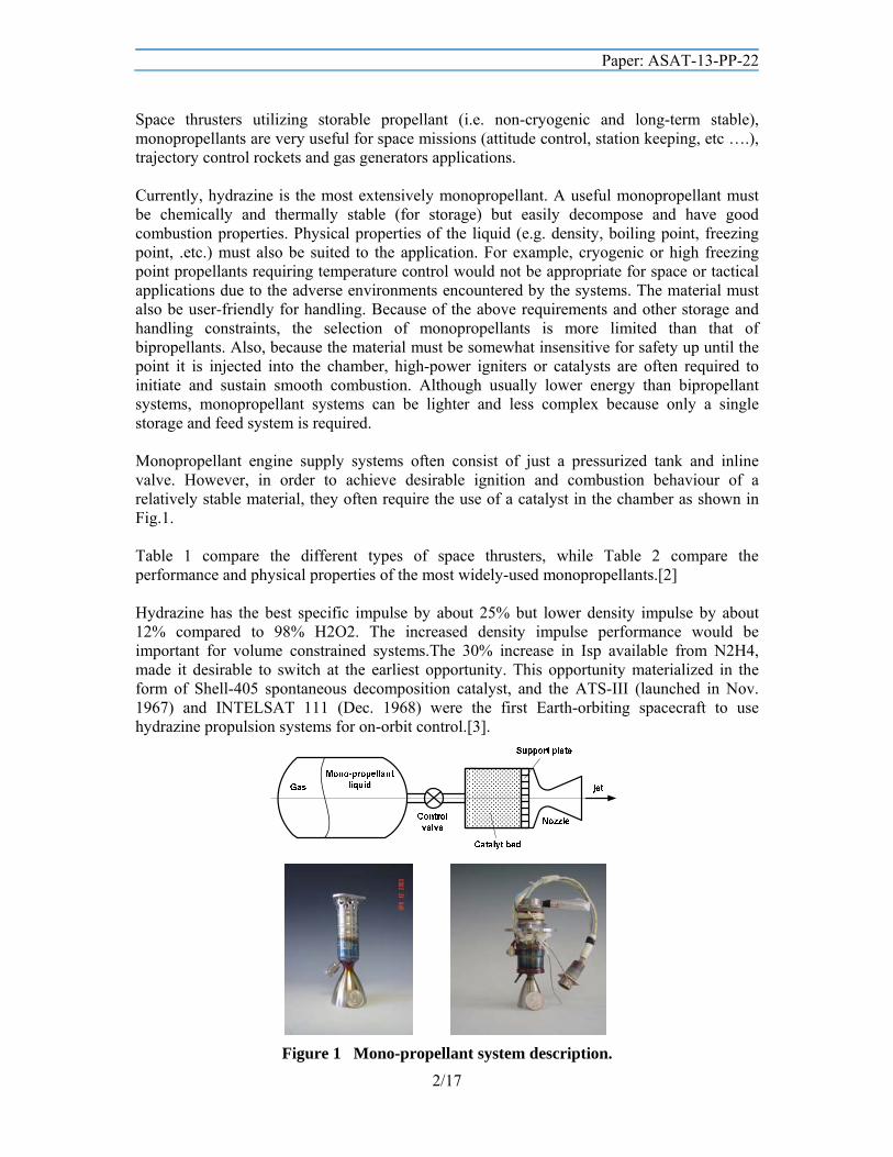
Space thrusters utilizing storable propellant (i.e. non-cryogenic and long-term stable), monopropellants are very useful for space missions (attitude control, station keeping, etc ….), trajectory control rockets and gas generators applications. Currently, hydrazine is the most extensively monopropellant. A useful monopropellant must be chemically and thermally stable (for storage) but easily decompose and have good combustion properties. Physical properties of the liquid (e.g. density, boiling point, freezing point, .etc.) must also be suited to the application. For example, cryogenic or high freezing point propellants requiring temperature control would not be appropriate for space or tactical applications due to the adverse environments encountered by the systems. The material must also be user-friendly for handling. Because of the above requirements and other storage and handling constraints, the selection of monopropellants is more limited than that of bipropellants. Also, because the material must be somewhat insensitive for safety up until the point it is injected into the chamber, high-power igniters or catalysts are often required to initiate and sustain smooth combustion. Although usually lower energy than bipropellant systems, monopropellant systems can be lighter and less complex because only a single storage and feed system is required. Monopropellant engine supply systems often consist of just a pressurized tank and inline valve. However, in order to achieve desirable ignition and combustion behaviour of a relatively stable material, they often require the use of a catalyst in the chamber as shown in Fig.1. Table 1 compare the different types of space thrusters, while Table 2 compare the performance and physical properties of the most widely-used monopropellants.[2] Hydrazine has the best specific impulse by about 25% but lower density impulse by about 12% compared to 98% H2O2. The increased density impulse performance would be important for volume constrained systems.The 30% increase in Isp available from N2H4, made it desirable to switch at the earliest opportunity. This opportunity materialized in the form of Shell-405 spontaneous decomposition catalyst, and the ATS-III (launched in Nov. 1967) and INTELSAT 111 (Dec. 1968) were the first Earth-orbiting spacecraft to use hydrazine propulsion systems for on-orbit control.[3].
Figure 1 Mono-propellant system description.
Paper: ASAT-13-PP-22
3/17
Table 1 Different types of space thrusters performance.
System type Specific Impulse, sec.
Density Specific Impulse, kg. sec./m3
Thrust, N
Cold gas thruster 60 - 250 (1.0 – 2.2)104 0.01 - 50 Mono-propellant thruster 130 - 280 (1.5 – 3.0)105 0.5 - 500 Bi-propellant thruster 300 - 450 (3.4 – 5.5)105 (0.1 – 1.2)107 Solid propulsion 260 - 300 (4.4 – 5.1)105 (10 – 1.3)107 Hybrid propulsion 290 - 350 (2.6 – 4.2)105 (10 – 1.3)107
Table 2 Comparison of Monopropellant Physical Properties.
H2O2(80%) N2H4 N2O Molecular mass, g/mol 34.01 32.05 44 Density kg/m3 1388 1020 1977.7 Heat of formation (kcal/mole) -44.88 +12.5 +15.5
Physical properties Liquid Colorless,
Burn skin & flammable
Liquid Colorless Toxic &
flammable
Colorless gas
Theoretical Performance (calculated using USAF Isp for Pc=7 bar,area ratio=40) Specific impulse, (sec) 160 191 152.7 Combustion Temperature, (K) 1274 896 1609
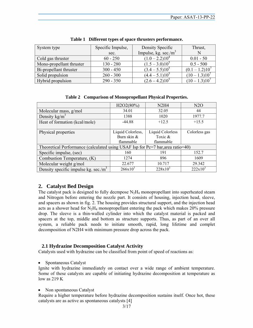
Molecular weight g/mol 22.677 10.717 29.342 Density specific impulse kg. sec./m3 266x103 228x103 222x103 2. Catalyst Bed Design The catalyst pack is designed to fully decmpose N2H4 monopropellant into superheated steam and Nitrogen before entering the nozzle part. It consists of housing, injection head, sleeve, and spacers as shown in fig. 2. The housing provides structural support, and the injection head acts as a shower head for N2H4 monopropellant entering the pack which makes 20% pressure drop. The sleeve is a thin-walled cylinder into which the catalyst material is packed and spacers at the top, middle and bottom as structure supports. Thus, as part of an over all system, a reliable pack needs to initiate smooth, rapid, long lifetime and complet decomposition of N2H4 with minimum pressure drop across the pack.
2.1 Hydrazine Decomposition Catalyst Activity Catalysts used with hydrazine can be classified from point of speed of reactions as: Spontaneous Catalyst Ignite with hydrazine immediately on contact over a wide range of ambient temperature. Some of these catalysts are capable of initiating hydrazine decomposition at temperature as low as 219 K Non spontaneous Catalyst Require a higher temperature before hydrazine decomposition sustains itself. Once hot, these catalysts are as active as spontaneous catalysts [4]
Paper: ASAT-13-PP-22
4/17
Fig. (2) Typical Hydrazine catalyst bed
Eberstein and Glassman (1960): noted that transition metals having in completed sub-shell act as strong catalysts for hydrazine decomposition, where as metals having no d shells or completely filled d shell are not catalytic [5]. Shell Development Company (1963) introduced the first spontaneous hydrazine decomposition catalysts. It was a ruthenium-iridium catalyst with 2.1-28% active metal on activated charcoal, one example consisted of 3.7% Ru and 4.3% Ir on activated charcoal. The most active catalysts described are those containing iridium or a mixture of iridium and ruthenium as active metals. The majority of work on hydrazine decomposition catalyst has been conducted with Shell 405,(32 % Iridium over support of alumina Al2O3) which is capable of surviving several hundred cold starts with no significant degradation, It is considered the most successful hydrazine decomposition catalyst to date. In view of the high cost of a 32% iridium catalyst. The use of ruthenium, which is cheaper than iridium is very promising alternative (Iridium price 27 US$ /g while Ruthenium cost 3.6 US$ /g ,a small engine delivering thrust of 100 N for 5 minutes require 800 g), there have been numerous attempts to replace Shell 405 with more economical catalysts containing less than 32% Ir.One of the many non-iridium catalyst as a potential replacement for shell 405 is ESSO 500 a 28% ruthenium catalyst but it can only used for 10 cold start.In Germany, Hydrazine decomposition catalysts are made by the Kali Chemie Company in Hanover. Interim results indicated that the German KC 12 G catalyst survived 241 cold (277-K hydrazine/277-K catalyst) starts in a 2-N thruster at DFVLR Trauen [4] Neto et al. (2003) studied the Ir/Al2O3, Ir-Ru/Al2O3 and Ru/Al2O3, catalysts with total metal contents of 30 % were prepared and tested in a 2N micro-thruster in vacuum chamber, performance compared with that of shell 405 commercial catalysts(30% Ir/Al2O3) and with prepared catalyst of 30% Ir/Al2O3. They found that using Ru have problems such as 50 % faster mechanical degradation and a higher decomposing instability, however they also demonstrated that the performance of this catalyst was compatible with their use in short-period space applications [6].
Paper: ASAT-13-PP-22
5/17
2.2 Catalyst Bed Design Parameters
a. Loading Factor The loading factor, G as the mass flux of mono-propellant as followings:
c
mG
A
(1)
where: m mass flow rate of N2H4 monopropellant, kg/sec., Ac cross-section area of catalyst pack, m2. Loading factor depend on the prepertaion of catalyst and configuration(packed bed or wire gauze or monolithic catalyst.) or Shell 405 the loading factor up to 400 kg m-2 sec-1[4].
b. Pressure Drop The minimum pressure drop is required, higher pressure drop requires higher delivery feed pressure. Drop pressure through packed bed not more than 6 bar shoud be attainable.
2.3 Catalyst Configuration The catalyst bed can take different forms:
a. Packed Bed (Packed Pellets) In characterizing the shape of granular catalysts, it has become common practice to classify them by the size of wire mesh screen (sieve) opening through which they passes for size distribution analysis. It is common practice to describe the size of the opening by how many openings one can measure per lineal inch and call this number "mesh". A 30 mesh sieve would thus have smaller opening than 25 mesh sieve. During initial tests of hydrazine thruster, cyclic instability in chmaber pressure occurred.the investigation showed that it was because the surface area of the catalyst was not sufficient to stabilize the flame front near the top of the catalyst bed. It was found that approximately 0.2 inch of 25-30 mesh catalyst located ay the top of the catalyst bed would produce smooth steady state opertaion (pressure oscillation 2:3 %). With the remainder of bed should be such that the ratio of thruster diameter to particle size diamter is at leasts 8:1(Fig. 2).
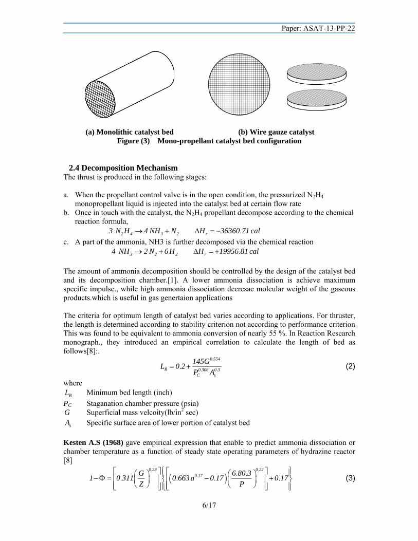
b. Monolith Catalyst(Fig. 3a.) A monolith is thus a single piece of stone. The diameter of the channels ranges from 0.5-10 mm and the length of the monolith can be up to 1 meter long. On the walls of the channels a catalytic active layer can be applied in which chemical reactions can take place. Because of the large number of channels, the contact area between the catalytic layer and the fluid that travels inside the channels is very large. Monolith catalyst used in catalyuic converter in automobile, some recent studies used it in hydrogen peroxide decomposition[16].
c. Wire Gauze(Fig 3b.) Gauze is a series of wire screens stacked one on top of other. The wire is typically made of platinum or a platinum-rhodium alloy. The wire diameter ranges between 0.004-0.01 cm. most used in hydrogen peroxide decomposition. Presented design rules for silver wire gauze catlayst bed for hydrogen peroxide thrusters. [7].
Paper: ASAT-13-PP-22
6/17
(a) Monolithic catalyst bed (b) Wire gauze catalyst Figure (3) Mono-propellant catalyst bed configuration
2.4 Decomposition Mechanism The thrust is produced in the following stages: a. When the propellant control valve is in the open condition, the pressurized N2H4
monopropellant liquid is injected into the catalyst bed at certain flow rate b. Once in touch with the catalyst, the N2H4 propellant decompose according to the chemical
reaction formula, .2 4 3 2 r3 N H 4 NH N H 36360 71 cal
c. A part of the ammonia, NH3 is further decomposed via the chemical reaction .3 2 2 r4 NH 2 N 6 H H 19956 81 cal
The amount of ammonia decomposition should be controlled by the design of the catalyst bed and its decomposition chamber.[1]. A lower ammonia dissociation is achieve maximum specific impulse., while high ammonia dissociation decresae molcular weight of the gaseous products.which is useful in gas genertaion applications The criteria for optimum length of catalyst bed varies according to applications. For thruster, the length is determined according to stability criterion not according to performance criterion This was found to be equivalent to ammonia conversion of nearly 55 %. In Reaction Research monograph., they introduced an empirical correlation to calculate the length of bed as follows[8]:.
.
. ..
0 554
B 0 306 0 3C s
145GL 0 2
P A (2)
where
BL Minimum bed length (inch)
PC Staganation chamber pressure (psia) G Superficial mass velcoity(lb/in2 sec)
sA Specific surface area of lower portion of catalyst bed
Kesten A.S (1968) gave empirical expression that enable to predict ammonia dissociation or chamber temperature as a function of steady state operating parameters of hydrazine reactor [8]
. .
. . .. . . .
0 28 0 220 17G 6 80 3
1 0 311 0 663 a 0 17 0 17Z P
(3)
Paper: ASAT-13-PP-22
7/17
. . . ..
PT 566 667 1 0 0 4167 852 778
6 803
(4)
where: Fractional ammonia dissociation; P Chamber pressure, bar; G Bed loading factor, kg/m2 sec; Z Reactor length (m); T Gas temperature (K) a Particle radius, m. These empirical correlations do not correctly predict the behavior of reactor in case the reaction is slow, for example in case reactors are uniformly packed with large catalyst particles such as 1/8 “ x 1/8 “ cylinders. The correlation work well in ranges of pressure less than 68 bar , bed loading 7-70 kg m-2 sec-1 and equivalent sphere radius 0.3-3 mm [8]. With the catalytic thruster just described, a specific Impulse, Isp=235 sec. is achieved when activated in normal mode (i.e. with nominal pulse width and duty cycles). When very short pulses are activated, the Isp is reduced by a factor of two or three [1]. 3: Mathematical Model for Hydrazine Decomposition
3.1 The governing equations
Species Equations Mole balance equations, we consider the reactions as: Heterogeneous Reaction (Reaction of N2H4 and ammonia on catalyst surface),
het het
1 22 4 3 2 2 3 2 2
1 1 1 3r rN H NH N H NH N H
2 2 2 2 (5)
Homogeneous Reactions (Thermal decomposition of N2H4 only),
hom
12 4 3 2 2
1 1rN H NH N H
2 2 (6)
where the reaction rate are taken from [10,13]as follow: Catalytic reaction rates can be written as For hydrazine catalytic decomosition
.
.2 4 2 4
2777 78het 10 T
1 N H r N Hr 1 0x10 e C k C (7)
For ammonia catalytic decomposition
.
. .. 3 3
4 4
27777 78NH NHhet 14 T
2 21 6 1 6H H
C Cr 1 0x10 e k
C C
(8)
Thermal (Homogenous) rates can be written as
Paper: ASAT-13-PP-22
8/17
For hydrazine thermal decomosition
.
hom .2 4 2 4
18333 3310 T
1 N H 3 N Hr 2 14x10 e C k C (9)
The reactions rates used, did not account for the mass transfer effects which may limit the heterogeneous reaction of N2H4, which give rise to the concept of effective reaction rate[3].
.
1 2 1 3
C s p p
AB AB
k A d Ud1 0
1 D 1 D
(10)
where kC Mass transfer coefficient (m sec-1) Gas density(kg/m3) U Superficial gas velocity(m/sec) Shape factor(external surface area divided by sphaere area) dp Pellet diameter(equivalent diamter of sphere of the same volume) Void fraction of packed bed depend on thruster diameter and pellet size, Range from
0.3-0.45[8] DAB gas phase diffusivity(m2/sec) μ Gas viscosity
As Specifc area of the catalyst bed (m2/m3) sp
1A 12
d
The effect of packed bed construction(pellet diameter) and bed loading enter in the model through the effect of mass transfer coefficient. The thruster may be classifiec according to this parameter as Reaction limited regime(kr<<kc) and diffusion limited (kc<< kr). To combine the mass transfer coefficient and reacton rate, The effective transport coefficient(equivalent reaction rate for the two step catalystic reaction of hydrazine and mass diffusion rate) (kC*=kCx As)
*
*c r
1 effc r
k kk k
k k
(11)
2 4 N H N H2 4 2 4
T 0 0N H 1 3 1 3
T 0 T u
C TP 1 Pr k k N k k N
N P T N R T
(12.a)
.
.
3 2 4 3 2
2 4 3 2
1
1 6T 0 0 T 0 0NH 1 3 N H 2 4 NH H
T 0 T 0
1
1 61 3 N H 2 4 NH H
T u T u
C T C TP Pr k k N k k N N
N P T N P T
1 P 1 Pk k N k k N N
N R T N R T
(12.b)
.
.
2 2 4 3 2
2 4 3 2
1
1 6T 0 0 T 0 0N 1 3 N H 2 4 NH H
T 0 T 0
1
1 61 3 N H 2 4 NH H
T u T u
C T C T1 P 1 Pr k k N k k N N
2 N P T 2 N P T
1 1 P 1 1 Pk k N k k N N
2 N R T 2 N R T
(12.c)
Paper: ASAT-13-PP-22
9/17
.
.
2 2 4 3 2
2 4 3 2
1
1 6T 0 0 T 0 0H 1 3 N H 2 4 NH H
T 0 T 0
1
1 61 3 N H 2 4 NH H
T u T u
C T C T1 P 3 Pr k k N k k N N
2 F P T 2 N P T
1 1 P 3 1 Pk k N k k N N
2 N R T 2 N R T
(12.d)
Finally, the species equations can be writtens as:
2 4 3
2 4 3
2 2
2 2
N H NHN H c NH c
N HN c H c
dN dNr A r A
dz dzdN dN
r A r Adz dz
(13)
where NT total molar flow rate,
Pressure drop Using of Ergun’s equation[12] for pressure drop across packed bed namely
.3
p p
300 1dP 2G 11 75G
dz r r
(14)
Energy Analysis Using the assumption of uniform flow at axial sections(Plug flow), and for q multiple reactions with m species the energy balance will be [3],
ij
j
q
Rxiji 1
cm
j pj 1
r H TdT
AdZ
N C
(15)
where rij Reaction rate of reaction number i weightted for species j
jpC Specific heat of species j
RxijH T Heat of reaction i for 1 mole of species j reacted in reaction i
jN Molar flow rate of species j
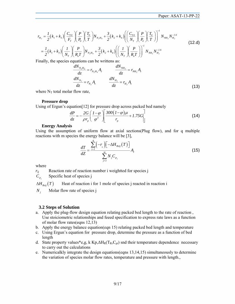
3.2 Steps of Solution a. Apply the plug-flow design equation relating packed bed length to the rate of reaction ,
Use stoiciometric relationships and feeed specification to express rate laws as a function of molar flow rates(eqns 12,13)
b. Apply the energy balance equation(eqn 15) relating packed bed length and temperature c. Using Ergun’s equation for pressure drop, determine the pressure as a function of bed
length d. State property values*e,g, k Kp,ΔHR(TR,Cpi) snd their temperature dependence necessary
to carry out the calculations e. Numericalkly integrate the design equations(eqns 13,14,15) simultaneously to determine
the variation of species molar flow rates, temperature and pressure with length.,
Paper: ASAT-13-PP-22
10/17
3.3 Numerical Algorithm The governing equations(eqns 13,14,15) are stiff equations (those equations that have widely different time scales). In solving such equations using a small value for the step size can introduce enough round-off errors to cause instability (increasing of error as time progress). To solve such problem, we make use of MATLAB package ode solvers (ode23s) which depend on modified second-order Rosenbock formulation which is a linearly implicit one-step method rather than the classical ode45 which make use of Runge-Kutta 4, 5 [13].In solution, Variations of specific heats as function in temperature are considered as in ref[14],[15]. 4: Results and Discussion
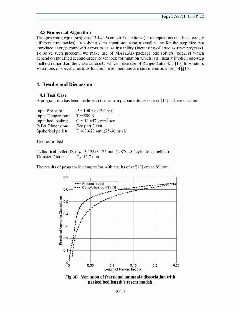
4.1 Test Case A program run has been made with the same input conditions as in ref[15] . These data are: Input Pressure P = 100 psia(7.4 bar) Input Temperature T = 500 K Input bed loading G = 14.647 kg/m2 sec Pellet Dimensions For first 5 mm Spaherical pellets Dp= 3.627 mm (25-30 mesh) The rest of bed Cylindrical pellet DpxLP =3.175x3.175 mm (1/8”x1/8” cylindrical pellets) Thruster Diameter Dc=12.7 mm The results of program in comparsion with results of ref[10] are as follow:
Fig (4) Variation of fractional ammonia dissociation with
packed bed length(Present model).

Paper: ASAT-13-PP-22
11/17
Fig(5) Variation of fractional ammonia dissociation with packed bed length[10].
Fig(6) Variation of gas temperature with packed bed length(present model).
Paper: ASAT-13-PP-22
12/17
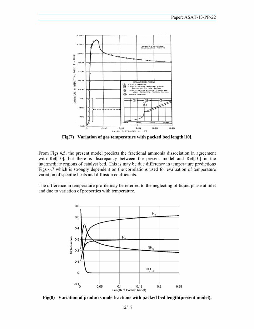
Fig(7) Variation of gas temperature with packed bed length[10].
From Figs.4,5, the present model predicts the fractional ammonia dissociation in agreement with Ref[10], but there is discrepancy between the present model and Ref[10] in the intermediate regions of catalyst bed. This is may be due difference in temperature predictions Figs 6,7 which is strongly dependent on the correlations used for evaluation of temperature variation of specific heats and diffusion coefficients. The difference in temperature profile may be referred to the neglecting of liquid phase at inlet and due to variation of properties with temperature.
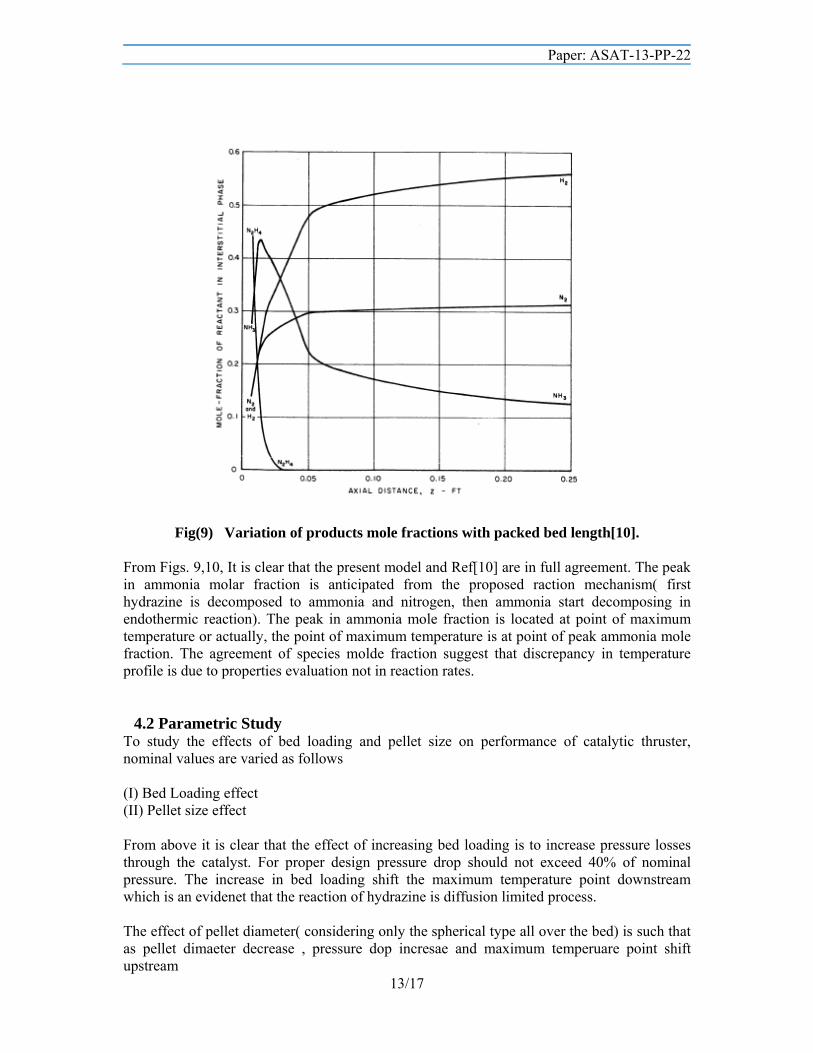
Fig(8) Variation of products mole fractions with packed bed length(present model).
Paper: ASAT-13-PP-22
13/17
Fig(9) Variation of products mole fractions with packed bed length[10]. From Figs. 9,10, It is clear that the present model and Ref[10] are in full agreement. The peak in ammonia molar fraction is anticipated from the proposed raction mechanism( first hydrazine is decomposed to ammonia and nitrogen, then ammonia start decomposing in endothermic reaction). The peak in ammonia mole fraction is located at point of maximum temperature or actually, the point of maximum temperature is at point of peak ammonia mole fraction. The agreement of species molde fraction suggest that discrepancy in temperature profile is due to properties evaluation not in reaction rates.
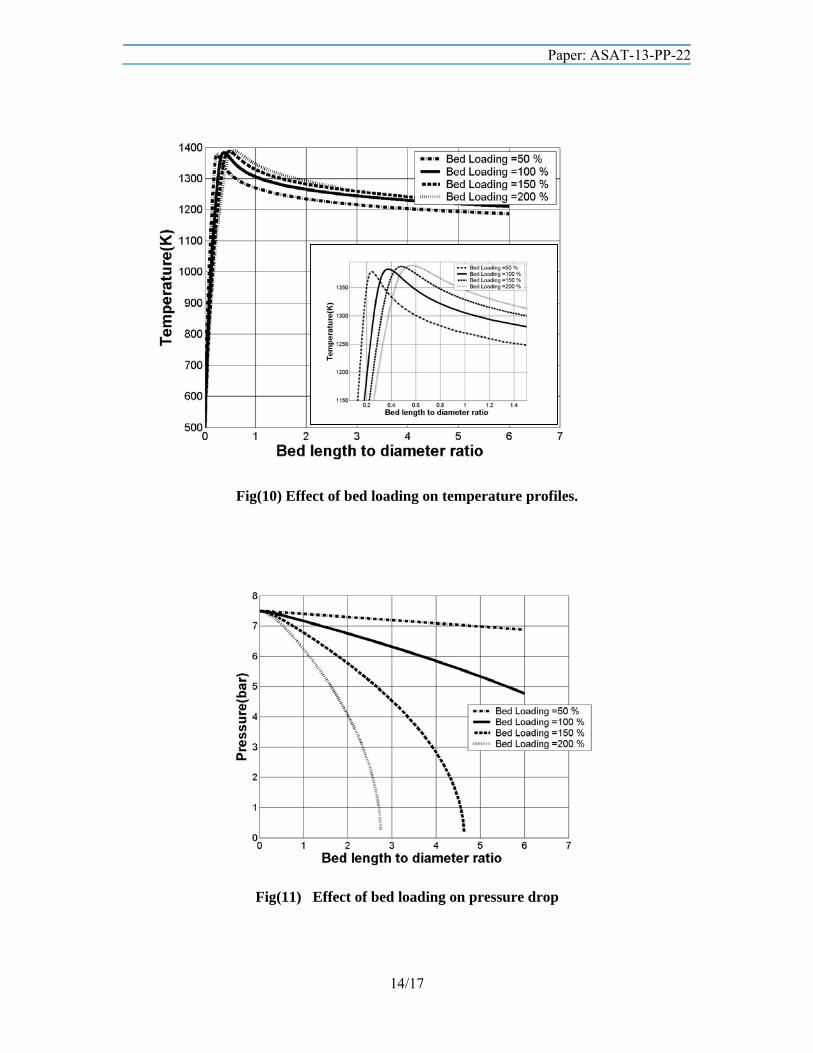
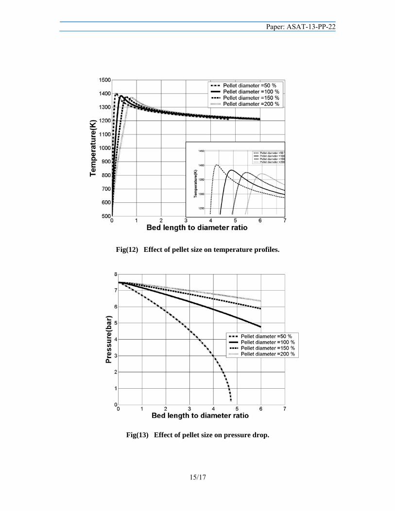
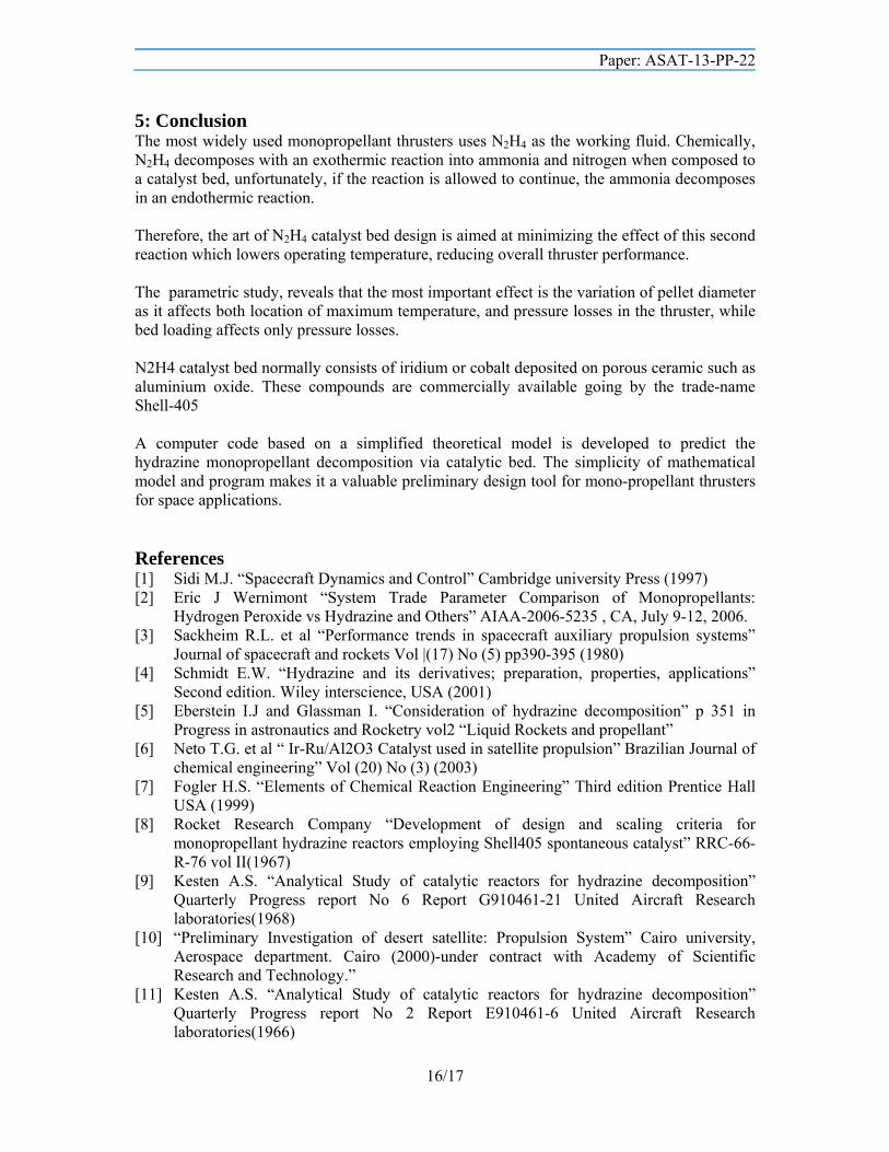
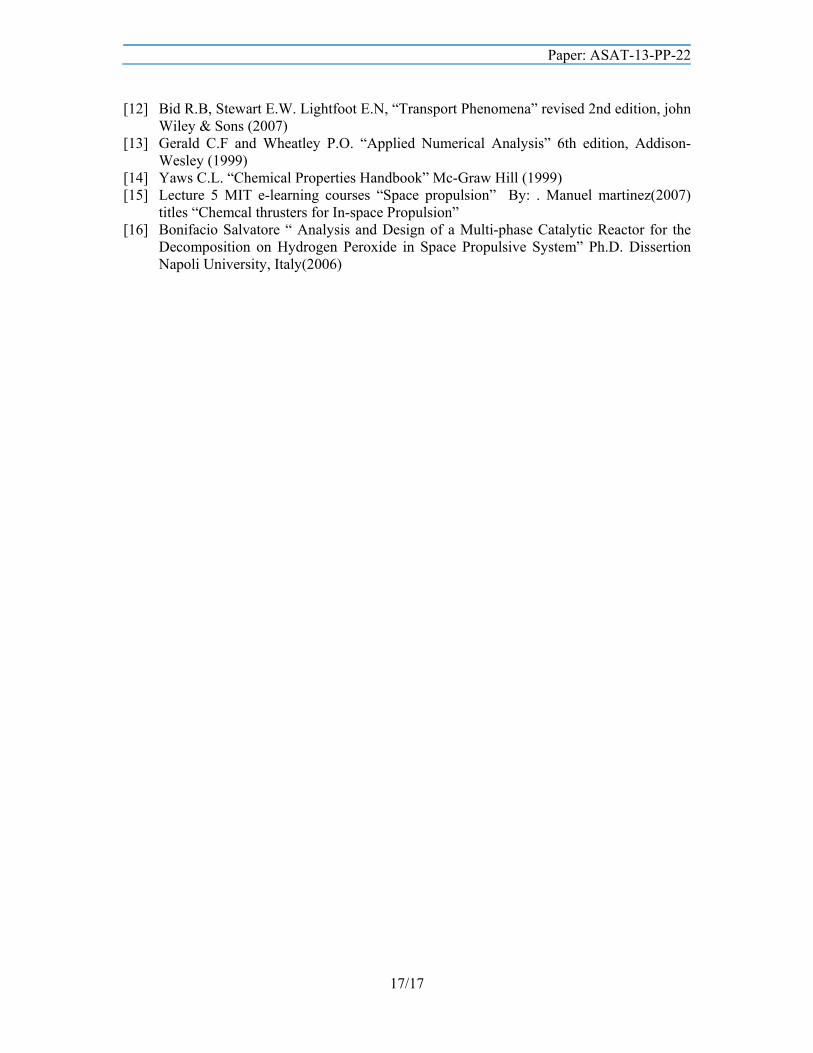
4.2 Parametric Study To study the effects of bed loading and pellet size on performance of catalytic thruster, nominal values are varied as follows (I) Bed Loading effect (II) Pellet size effect From above it is clear that the effect of increasing bed loading is to increase pressure losses through the catalyst. For proper design pressure drop should not exceed 40% of nominal pressure. The increase in bed loading shift the maximum temperature point downstream which is an evidenet that the reaction of hydrazine is diffusion limited process. The effect of pellet diameter( considering only the spherical type all over the bed) is such that as pellet dimaeter decrease , pressure dop incresae and maximum temperuare point shift upstream
Paper: ASAT-13-PP-22
14/17
Fig(10) Effect of bed loading on temperature profiles.
Fig(11) Effect of bed loading on pressure drop
Paper: ASAT-13-PP-22
15/17
Fig(12) Effect of pellet size on temperature profiles.
Fig(13) Effect of pellet size on pressure drop.
Paper: ASAT-13-PP-22
16/17
5: Conclusion The most widely used monopropellant thrusters uses N2H4 as the working fluid. Chemically, N2H4 decomposes with an exothermic reaction into ammonia and nitrogen when composed to a catalyst bed, unfortunately, if the reaction is allowed to continue, the ammonia decomposes in an endothermic reaction. Therefore, the art of N2H4 catalyst bed design is aimed at minimizing the effect of this second reaction which lowers operating temperature, reducing overall thruster performance. The parametric study, reveals that the most important effect is the variation of pellet diameter as it affects both location of maximum temperature, and pressure losses in the thruster, while bed loading affects only pressure losses. N2H4 catalyst bed normally consists of iridium or cobalt deposited on porous ceramic such as aluminium oxide. These compounds are commercially available going by the trade-name Shell-405 A computer code based on a simplified theoretical model is developed to predict the hydrazine monopropellant decomposition via catalytic bed. The simplicity of mathematical model and program makes it a valuable preliminary design tool for mono-propellant thrusters for space applications. References [1] Sidi M.J. “Spacecraft Dynamics and Control” Cambridge university Press (1997) [2] Eric J Wernimont “System Trade Parameter Comparison of Monopropellants:
Hydrogen Peroxide vs Hydrazine and Others” AIAA-2006-5235 , CA, July 9-12, 2006. [3] Sackheim R.L. et al “Performance trends in spacecraft auxiliary propulsion systems”
Journal of spacecraft and rockets Vol |(17) No (5) pp390-395 (1980) [4] Schmidt E.W. “Hydrazine and its derivatives; preparation, properties, applications”
Second edition. Wiley interscience, USA (2001) [5] Eberstein I.J and Glassman I. “Consideration of hydrazine decomposition” p 351 in
Progress in astronautics and Rocketry vol2 “Liquid Rockets and propellant” [6] Neto T.G. et al “ Ir-Ru/Al2O3 Catalyst used in satellite propulsion” Brazilian Journal of
chemical engineering” Vol (20) No (3) (2003) [7] Fogler H.S. “Elements of Chemical Reaction Engineering” Third edition Prentice Hall
USA (1999) [8] Rocket Research Company “Development of design and scaling criteria for
monopropellant hydrazine reactors employing Shell405 spontaneous catalyst” RRC-66-R-76 vol II(1967)
[9] Kesten A.S. “Analytical Study of catalytic reactors for hydrazine decomposition” Quarterly Progress report No 6 Report G910461-21 United Aircraft Research laboratories(1968)
[10] “Preliminary Investigation of desert satellite: Propulsion System” Cairo university, Aerospace department. Cairo (2000)-under contract with Academy of Scientific Research and Technology.”
[11] Kesten A.S. “Analytical Study of catalytic reactors for hydrazine decomposition” Quarterly Progress report No 2 Report E910461-6 United Aircraft Research laboratories(1966)
Paper: ASAT-13-PP-22
17/17
[12] Bid R.B, Stewart E.W. Lightfoot E.N, “Transport Phenomena” revised 2nd edition, john Wiley & Sons (2007)
[13] Gerald C.F and Wheatley P.O. “Applied Numerical Analysis” 6th edition, Addison-Wesley (1999)
[14] Yaws C.L. “Chemical Properties Handbook” Mc-Graw Hill (1999) [15] Lecture 5 MIT e-learning courses “Space propulsion” By: . Manuel martinez(2007)
titles “Chemcal thrusters for In-space Propulsion” [16] Bonifacio Salvatore “ Analysis and Design of a Multi-phase Catalytic Reactor for the
Decomposition on Hydrogen Peroxide in Space Propulsive System” Ph.D. Dissertion Napoli University, Italy(2006)
Related Documents