Modeling of flexural behavior of RC beams strengthened with mechanically fastened FRP strips Fabio Nardone ⇑ , Gian Piero Lignola, Andrea Prota, Gaetano Manfredi, Antonio Nanni Department of Structural Engineering, University of Naples, Federico II, Via Claudio 21, Naples, P.O. Box I-80125, Italy article info Article history: Available online 16 March 2011 Keywords: Analytical modeling RC members Fiber-reinforced polymers (FRP) Fasteners Strengthening abstract An alternative to fiber reinforced polymer (FRP) materials adhesively bonded to the concrete substrate is the implementation of mechanically fastened FRP (MF-FRP) systems using steel anchors to secure the laminate to the substrate. The benefit of MF-FRP, compared to adhesive bonding for FRP flexural strength- ening, is the speed of installation with unskilled labor, minimal or absent surface preparation under any meteorological condition and immediate use of the strengthened structures. Some of the potential short- comings are: possible concrete damage during anchoring and limited opportunity of installation in the presence of congested internal reinforcement in the members to be strengthened. Laboratory testing and a number of field applications have shown the effectiveness of the MF-FRP method. In this paper, an analytical model is discussed for reinforced concrete (RC) members strengthened with MF-FRP strips. The model accounts for equilibrium, compatibility and constitutive relationships of the constituent mate- rials; in particular, it accounts explicitly for the slip between the substrate surface and the FRP strip due to the behavior of the fasteners. The proposed flexural model, coupled with the computation algorithm, is able to predict the fundamentals of the behavior of RC flexural members strengthened with MF-FRP strips, in terms of both ultimate and serviceability limit states. Comparisons between the analytical pre- dictions and the experimental results have been successfully performed. Ó 2011 Elsevier Ltd. All rights reserved. 1. Introduction In the last decades, an increasing demand for strengthening, retrofitting and repairing civil infrastructures has developed. The reasons are mainly related to: materials deterioration, demand for higher loads and seismic upgrade. The use of FRP for repairing and strengthening of masonry and concrete structures has become an accepted engineering practice around the world because using FRP systems is relatively economical and fast. Consequently, many international guidelines published throughout the world by differ- ent organizations including ACI in USA [1], fib in Europe [2] and CNR in Italy [3] deal with the design of FRP as external reinforce- ment. Usually, FRP materials are externally bonded (EB-FRP) with epoxy to the substrate, but an innovative technique based on the use of mechanical fastening (MF-FRP) has recently emerged. The benefit of MF-FRP system, compared to EB-FRP flexural strengthen- ing are speed of installation using unskilled labor, minimal or ab- sent surface preparation under any meteorological condition, and immediate use of the strengthened structures. Some of the poten- tial shortcomings are: brittle failure modes; possible concrete damage during fastener installation; and, difficulty installation in the presence of congested internal reinforcement. The feasibility of this technique for external strengthening of reinforced concrete (RC) members has been investigated by researchers. There are examples of RC bridges in Wisconsin strengthened using MF-FRP system [4]. The viability of this technology has been extensively tested in Missouri in a number of field applications [5–7]. Laboratory tests have shown the effectiveness of such method, for example Bank et al. [8] showed that the load capacity increased by up to 60% when using this strengthening technique. Lamanna et al. [9] conducted a series of 15 flexural tests where the effects of different fastener lengths and layouts as well as predrilling were examined. An investigation to evaluate the short-term effects of simultaneous environmental exposure and sustained load on RC beams was performed by Lee et al. [10]. After observing and veri- fying the slip effect at the connection between FRP and concrete, they introduced a FRP strain reduction factor calibrated on the ba- sis of the experimental results in order to evaluate the nominal moment capacity. Recently, an experimental program was carried out by Napoli [11] using different fastener layout. Despite the interest and prom- ising experimental results obtained by researchers, there are no international guidelines dealing with MF-FRP at this time. 0263-8223/$ - see front matter Ó 2011 Elsevier Ltd. All rights reserved. doi:10.1016/j.compstruct.2011.03.003 ⇑ Corresponding author. Tel.: +39 081 7683672; fax: +39 081 7683491. E-mail address: [email protected] (F. Nardone). Composite Structures 93 (2011) 1973–1985 Contents lists available at ScienceDirect Composite Structures journal homepage: www.elsevier.com/locate/compstruct

Welcome message from author
This document is posted to help you gain knowledge. Please leave a comment to let me know what you think about it! Share it to your friends and learn new things together.
Transcript

Composite Structures 93 (2011) 1973–1985
Contents lists available at ScienceDirect
Composite Structures
journal homepage: www.elsevier .com/locate /compstruct
Modeling of flexural behavior of RC beams strengthened with mechanically fastenedFRP strips
Fabio Nardone ⇑, Gian Piero Lignola, Andrea Prota, Gaetano Manfredi, Antonio NanniDepartment of Structural Engineering, University of Naples, Federico II, Via Claudio 21, Naples, P.O. Box I-80125, Italy
a r t i c l e i n f o
Article history:Available online 16 March 2011
Keywords:Analytical modelingRC membersFiber-reinforced polymers (FRP)FastenersStrengthening
0263-8223/$ - see front matter � 2011 Elsevier Ltd. Adoi:10.1016/j.compstruct.2011.03.003
⇑ Corresponding author. Tel.: +39 081 7683672; faxE-mail address: [email protected] (F. Nardon
a b s t r a c t
An alternative to fiber reinforced polymer (FRP) materials adhesively bonded to the concrete substrate isthe implementation of mechanically fastened FRP (MF-FRP) systems using steel anchors to secure thelaminate to the substrate. The benefit of MF-FRP, compared to adhesive bonding for FRP flexural strength-ening, is the speed of installation with unskilled labor, minimal or absent surface preparation under anymeteorological condition and immediate use of the strengthened structures. Some of the potential short-comings are: possible concrete damage during anchoring and limited opportunity of installation in thepresence of congested internal reinforcement in the members to be strengthened. Laboratory testingand a number of field applications have shown the effectiveness of the MF-FRP method. In this paper,an analytical model is discussed for reinforced concrete (RC) members strengthened with MF-FRP strips.The model accounts for equilibrium, compatibility and constitutive relationships of the constituent mate-rials; in particular, it accounts explicitly for the slip between the substrate surface and the FRP strip dueto the behavior of the fasteners. The proposed flexural model, coupled with the computation algorithm, isable to predict the fundamentals of the behavior of RC flexural members strengthened with MF-FRPstrips, in terms of both ultimate and serviceability limit states. Comparisons between the analytical pre-dictions and the experimental results have been successfully performed.
� 2011 Elsevier Ltd. All rights reserved.
1. Introduction
In the last decades, an increasing demand for strengthening,retrofitting and repairing civil infrastructures has developed. Thereasons are mainly related to: materials deterioration, demandfor higher loads and seismic upgrade. The use of FRP for repairingand strengthening of masonry and concrete structures has becomean accepted engineering practice around the world because usingFRP systems is relatively economical and fast. Consequently, manyinternational guidelines published throughout the world by differ-ent organizations including ACI in USA [1], fib in Europe [2] andCNR in Italy [3] deal with the design of FRP as external reinforce-ment. Usually, FRP materials are externally bonded (EB-FRP) withepoxy to the substrate, but an innovative technique based on theuse of mechanical fastening (MF-FRP) has recently emerged. Thebenefit of MF-FRP system, compared to EB-FRP flexural strengthen-ing are speed of installation using unskilled labor, minimal or ab-sent surface preparation under any meteorological condition, andimmediate use of the strengthened structures. Some of the poten-
ll rights reserved.
: +39 081 7683491.e).
tial shortcomings are: brittle failure modes; possible concretedamage during fastener installation; and, difficulty installation inthe presence of congested internal reinforcement. The feasibilityof this technique for external strengthening of reinforced concrete(RC) members has been investigated by researchers. There areexamples of RC bridges in Wisconsin strengthened using MF-FRPsystem [4]. The viability of this technology has been extensivelytested in Missouri in a number of field applications [5–7].
Laboratory tests have shown the effectiveness of such method,for example Bank et al. [8] showed that the load capacity increasedby up to 60% when using this strengthening technique. Lamannaet al. [9] conducted a series of 15 flexural tests where the effectsof different fastener lengths and layouts as well as predrilling wereexamined. An investigation to evaluate the short-term effects ofsimultaneous environmental exposure and sustained load on RCbeams was performed by Lee et al. [10]. After observing and veri-fying the slip effect at the connection between FRP and concrete,they introduced a FRP strain reduction factor calibrated on the ba-sis of the experimental results in order to evaluate the nominalmoment capacity.
Recently, an experimental program was carried out by Napoli[11] using different fastener layout. Despite the interest and prom-ising experimental results obtained by researchers, there are nointernational guidelines dealing with MF-FRP at this time.

Nomenclature
a depth of equivalent rectangular stress block (mm)b width of the RC beam (mm)c depth of the neutral axis (mm)dc concrete cover thickness of the RC beam (mm)ds distance to the centroid of the steel from the top of the
beam (mm)df fastener diameter (mm)f local bearing stress (MPa)fb sustained bearing stress of the FRP strip (MPa)ff bearing yield stress of the FRP strip (MPa)f 0c specified compressive strength of concrete (MPa)f frp,u tensile strength in the MF-FRP strip (MPa)fs stress of the steel reinforcement in tension (MPa)fy yield stress of the steel reinforcement (MPa)f0 open-hole tensile strength of the FRP strip (MPa)nh number of the fasteners available at the section xq(x) distributed load for unit length acting on the RC beam
(N L�1)s relative displacement between the RC beam and the FRP
strip (mm)sb slip corresponding to bearing yield stress (mm)s�b slip corresponding to sustained bearing stress in the
bilinearized curve (mm)sf slip corresponding to bearing yield stress (mm)smax maximum value of the slip (mm)tfrp MF-FRP strip thickness (mm)wfrp displacement of the FRP strip (mm)wc,inf. displacement of the lower fiber of the RC beam (mm)x position of current section along the beam (mm)xi position of the fastener i along the beam (mm)A coefficient to be calibrated for slip function (Eq. (27))Afrp gross area of the FRP strip cross-section (mm2)As area of the steel reinforcement in tension (mm2)B coefficient to be calibrated for slip function (Eq. (27))C coefficient to be calibrated for slip function (Eq. (27))D coefficient to be calibrated for slip function (Eq. (27))K0 initial slope of function Nh�s (N/mm)K00 post elastic slope of function Nh�s (N/mm)Ec Young’s modulus of concrete (MPa)Efrp Young’s modulus of FRP strips (MPa)H height of the RC beam (mm)In moment of inertia of the RC beam section (mm4)L distance between the first fastener and symmetry axis
(mm)Mc global bending moment acting on the RC beam (N mm)Mn nominal moment capacity of the MF-FRP strengthened
RC beam (theoretical) (N mm)Mu ultimate moment capacity of the MF-FRP strengthened
RC beam (experimental) (N mm)
M(x) global bending moment acting on the section x (N mm)Nb force acting on the fastener at which the sustained bear-
ing stress is attained in the FRP strip (N)Nc axial load applied on the RC beam (N)Ncc the force resultant in the equivalent rectangular com-
pressive stress distribution (stress block) (N)Nf force acting on the fastener at which the bearing yield
stress is attained in the FRP strip (N)Nfrp axial load acting on the FRP strip (N)Nfrp,max maximum axial load acting on the FRP strip (N)Nh force acting on the fastener (N)Nhi force acting on the fastener i placed before the current
section xi (N)Nh,max maximum value of the force acting on the fastener (N)N0 force acting on the MF-FRP strip at which the net ten-
sion failure is attained (N)Nsteel the force resultant in the steel reinforcement in tension
(N)V(x) global shear force on the section x (N)Vc shear force acting on the RC beam (N)ec,inf. strain level in the concrete fiber located at the soffit of
the beam (mm/mm)ec,sup. strain level in the concrete fiber located at the upper-
most of the RC section (mm/mm)ecu compressive failure strain in the concrete (mm/mm)efrp effective strain in the FRP strip (mm/mm)efrp,u ultimate strain in FRP strip (mm/mm)es strain at the steel reinforcement in tension (mm/mm)a calibration coefficient (Eq. (1))b calibration coefficient (Eq. (1))b1 ratio of the depth of the equivalent rectangular stress
block to the depth of the neutral axisc multiplier of f 0c to determine the intensity of equivalent
rectangular stress distribution for concretev curvature of the RC beam (mm�1)vu ultimate curvature of the RC beam (mm�1)DMc variation of the bending moment acting on the RC beam
(N mm)DNc variation of the axial load acting on the RC beam (N)DNfrp variation of the axial load acting on the FRP strip (N)DVc variation of the shear force acting on the RC beam (N)Dx variation of the position of current section along the
beam (mm)Dxi length of part i in which the length L of the RC member
is divided (mm)s shear stress (MPa)
1974 F. Nardone et al. / Composite Structures 93 (2011) 1973–1985
2. Research significance and objectives
The analytical models available in literature for the design of RCmembers strengthened with MF-FRP system deal with the ultimatelimit state and assume that there is no relative slip between theconcrete surface and the laminate. This can lead to an incorrectevaluation of the neutral axis depth. The objective of this study isto propose an analytical model able to predict the flexural behaviorof RC members strengthened using MF-FRP strips, both at service-ability and ultimate limit states. The model accounts for equilib-rium, compatibility and constitutive relationships of materials; inparticular, it accounts explicitly for the slip between the concretesurface and the FRP strip due to the fasteners. The proposed model,
coupled with an appropriate computation algorithm, is able to pre-dict the fundamentals of flexural behavior of RC membersstrengthened with MF-FRP strips also in terms of load vs. deflectioncurves, failure modes, strain profiles and curvatures.
3. Bearing models
In order to consider explicitly the slip between the concretesubstrate and the FRP strip due to the behavior of the fasteners,it is important to characterize the shear capacity of the fastener-concrete-FRP connection [10]. Experimental studies showed thatthe mechanical behavior of MF-FRP strengthened beams is pseu-do-ductile due to the local bearing failure occurring in the FRP

F. Nardone et al. / Composite Structures 93 (2011) 1973–1985 1975
strips at the fastener locations [4,8,9,12]. Bearing tests on concreteblocks with FRP strips fastened as per ASTM D5961 [13] providethe load vs. slip relationship and show that the behavior of theMF-FRP connection is linear-elastic up to the value of the bearingstress. The sustained bearing stress, fb, is the stress at which a pro-gressive and sustained bearing failure is attained and is a key de-sign property for the MF-FRP system [12] along with the load vs.displacement plot for typical specimens tested in pin bearing.The bearing test data show that the FRP strip has a perfectly plasticor hardening response once the sustained bearing failure isinitiated.
Elsayed et al. [14] reported experimental results from 23 sheartests on special hybrid glass/carbon MF-FRP. The FRP strip dimen-sions were 650 � 50 � 3.2 mm and were attached to the concreteblocks with dimensions of 150 � 150 � 400 mm. The strips werecentered and clamped at the top of the concrete block. The fastenerwere driven or hammered into the concrete in premarked loca-tions. A constant fastened length of 250 mm was maintained forall the specimens.
Both shot and screw-type fasteners were used to install the FRPcomposites on concrete blocks and based on these experimentalresults, the authors developed by regression analysis the bear-ing–slip model for both types of fasteners. The mechanical behav-ior of the FRP/concrete interface was modeled as a relationshipbetween the local bearing stress, f, and the relative displacement,s, between the FRP strip and the concrete. The f–s relationship pro-posed by Elsayed et al. [14] is as shown in the following equation:
f ¼ ff ssf
if s 6 sf ;
f ¼ ffssf
� �exp �a s=sfð Þb� �
if sf < s < sb;
f ¼ fb ðfor screw-type fastenerÞ if s P sb;
f ¼ ff
0:167 coshðs=sbÞ2b
� fb
0:496 sinhðs=sbÞ2bðfor shot fastenerÞ if s P sb
ð1Þ
where fb is the stress at sustained bearing in the FRP strip and sb isthe corresponding slip; ff is the bearing yield stress of the FRP stripand sf is the corresponding slip; a and b are calibration coefficients.
In the model proposed by Elsayed et al. [14] after an elasticbranch (slip s lower than sf), there is a joining branch before thesustained bearing slip, sb; afterwards, the behavior is perfectly
f b
slip,s [mm]sb*sf
Eq.(1)f f
sb
f[MPa]
K''/df tfrp
K'/df tfrp
(a)
K'
K''
slip,s [mm]sb*sf
N h
[kN]
N b
N f
(b)
Fig. 1. Stress (a) and force (b) vs. slip in double shear bearing test for MF-FRP strip.
plastic for screw-type fasteners, while it is softening for shot-typefasteners. In Fig. 1a, Eq. (1) is also compared to a simplified elastic-hardening model characterized by the two stiffnesses, K0/dftfrp
(equal to ff/sf) and K00/dftfrp, where s�b = fb/K0dftfrp. The scope of theproposed model is to provide simplified equations at ultimate limitstate.
4. Analytical flexural model for MF-FRP strengthened membersat ultimate limit state
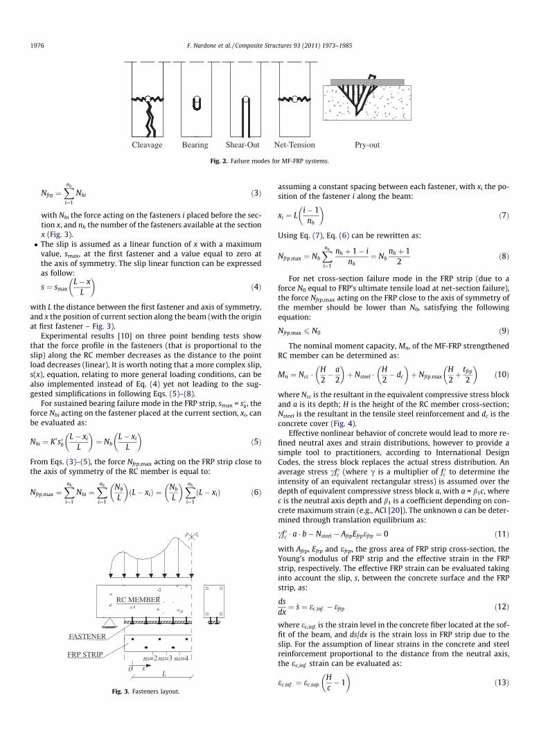
The typical failure modes of MF-FRP systems can be summa-rized as follows: cleavage, bearing, shear-out, net tension, andpry-out (Fig. 2). The cleavage failure (also called block shear) ischaracterized by a crack parallel to the applied load. The bearingfailure occurs predominantly when the fastener diameter to stripwidth ratio is small. Increasing the width-to-hole-diameter ratioup to a limiting value of 5 can increase the bearing strength[15,16]. This failure mode leads to an elongation of the hole. Theshear-out is a particular case of bearing failure mode when theelongation of the fastener hole develops up to the free edge [17].The net-tension failure mode is characterized by a fracture acrossthe net FRP cross-section, developing perpendicularly to the direc-tion of loading. This failure occurs when the fastener diameter islarge compared to strip width [5]. The pry-out failure is due tothe concrete damage in front and behind the fastener, causingthe fastener to pull out [12,18].
The shear-out, pry-out and cleavage failure modes can beavoided adopting a minimum distance between the holes and be-tween the holes and the free edges of the FRP strip [11]. In order toprevent the occurrence of the first two failure modes (shear-outand pry-out), 3 in. (76.2 mm) fasteners spacing is the minimumrecommended distance [17]; this is also the minimum value sug-gested by most fastener manufactures for constructability issues.In order to prevent the cleavage failure at the end fasteners, theedge distance of 2.5 in. (63.5 mm) is the minimum value recom-mended by Lamanna [19]; additionally, it is also a suitable distancefor preventing premature shear-out failures in the FRP strip at theoutmost fasteners [5]. Therefore, the failure modes investigated inthis analytical model are: bearing; net tension; in addition tocrushing of the compressed concrete.
The following assumptions are made in the proposed analyticalmodel for flexural behavior of simply supported RC membersstrengthened with MF-FRP strips:
� Strains in the concrete and steel reinforcement are proportionalto the distance from the neutral axis (that is, a plane sectionbefore loading remains plane after loading only for the RCcross-section).� Crushing of compressed concrete occurs at a maximum ulti-
mate compressive strain, ecu. The stress block (rectangular dis-tribution of concrete stresses in compression) is assumed.� The tensile strength of concrete is ignored.� The steel reinforcing bars have elastic perfectly plastic behavior.� The stress and strain distributions across the width of the strip
are assumed uniform [12]. This assumption ignores shear lagand the stress, f, is given by dividing the force on the fastenerNh by df (fastener diameter) and tfrp (thickness of the MF-FRPstrip).� A bilinear force acting on the fastener vs. slip curve (Nh–s acting
on the fastener) is assumed (Fig. 1b) with initial slope:
K 0 ¼ Nf
sfð2Þ
� The force acting on the FRP strip, Nfrp, at the section x can beevaluated, as:
Net-TensionCleavage Bearing Shear-Out Pry-out
Fig. 2. Failure modes for MF-FRP systems.
1976 F. Nardone et al. / Composite Structures 93 (2011) 1973–1985
Nfrp ¼Xnh
i¼1
Nhi ð3Þ
with Nhi the force acting on the fasteners i placed before the sec-tion x, and nh the number of the fasteners available at the sectionx (Fig. 3).� The slip is assumed as a linear function of x with a maximum
value, smax, at the first fastener and a value equal to zero atthe axis of symmetry. The slip linear function can be expressedas follow:
s ¼ smaxL� x
L
� �ð4Þ
with L the distance between the first fastener and axis of symmetry,and x the position of current section along the beam (with the originat first fastener – Fig. 3).
Experimental results [10] on three point bending tests showthat the force profile in the fasteners (that is proportional to theslip) along the RC member decreases as the distance to the pointload decreases (linear). It is worth noting that a more complex slip,s(x), equation, relating to more general loading conditions, can bealso implemented instead of Eq. (4) yet not leading to the sug-gested simplifications in following Eqs. (5)–(8).
For sustained bearing failure mode in the FRP strip, smax = s�b, theforce Nhi acting on the fastener placed at the current section, xi, canbe evaluated as:
Nhi ¼ K 0s�bL� xi
L
� �¼ Nb
L� xi
L
� �ð5Þ
From Eqs. (3)–(5), the force Nfrp,max acting on the FRP strip close tothe axis of symmetry of the RC member is equal to:
Nfrp;max ¼Xnh
i¼1
Nhi ¼Xnh
i¼1
Nb
L
� �ðL� xiÞ ¼
Nb
L
� �Xnh
i¼1
ðL� xiÞ ð6Þ
nh=2x0
L
RC MEMBER
FRP STRIP
FASTENER
nh=3 nh=4
Fig. 3. Fasteners layout.
assuming a constant spacing between each fastener, with xi the po-sition of the fastener i along the beam:
xi ¼ Li� 1
nh
� �ð7Þ
Using Eq. (7), Eq. (6) can be rewritten as:
Nfrp;max ¼ Nb
Xnh
i¼1
nh þ 1� inh
¼ Nbnh þ 1
2ð8Þ
For net cross-section failure mode in the FRP strip (due to aforce N0 equal to FRP’s ultimate tensile load at net-section failure),the force Nfrp,max acting on the FRP close to the axis of symmetry ofthe member should be lower than N0, satisfying the followingequation:
Nfrp;max 6 N0 ð9Þ
The nominal moment capacity, Mn, of the MF-FRP strengthenedRC member can be determined as:
Mn ¼ Ncc �H2� a
2
� �þ Nsteel �
H2� dc
� �þ Nfrp;max
H2þ tfrp
2
� �ð10Þ
where Ncc is the resultant in the equivalent compressive stress blockand a is its depth; H is the height of the RC member cross-section;Nsteel is the resultant in the tensile steel reinforcement and dc is theconcrete cover (Fig. 4).
Effective nonlinear behavior of concrete would lead to more re-fined neutral axes and strain distributions, however to provide asimple tool to practitioners, according to International DesignCodes, the stress block replaces the actual stress distribution. Anaverage stress cf 0c (where c is a multiplier of f 0c to determine theintensity of an equivalent rectangular stress) is assumed over thedepth of equivalent compressive stress block a, with a = b1c, wherec is the neutral axis depth and b1 is a coefficient depending on con-crete maximum strain (e.g., ACI [20]). The unknown a can be deter-mined through translation equilibrium as:
cf 0c � a � b� Nsteel � AfrpEfrpefrp ¼ 0 ð11Þ
with Afrp, Efrp and efrp, the gross area of FRP strip cross-section, theYoung’s modulus of FRP strip and the effective strain in the FRPstrip, respectively. The effective FRP strain can be evaluated takinginto account the slip, s, between the concrete surface and the FRPstrip, as:
dsdx¼ _s ¼ ec;inf : � efrp ð12Þ
where ec,inf. is the strain level in the concrete fiber located at the sof-fit of the beam, and ds/dx is the strain loss in FRP strip due to theslip. For the assumption of linear strains in the concrete and steelreinforcement proportional to the distance from the neutral axis,the ec,inf. strain can be evaluated as:
ec;inf : ¼ ec;sup:Hc� 1
� �ð13Þ

c
b εc,sup.
a
γ f 'c
As Nsteel
Ncc
Nfrp,max
Nsteel
Ncc
Nfrp,maxAfrp
neutral axis
dc
ReinforcedConcrete Section
StrainDistribution
Force Equilibrium(Non-linear ConcreteStress Distribution)
Force Equilibrium(Equivalent ConcreteStress Distribution)
εfrps
H ds
εs
εc,inf.
Fig. 4. Assumed strain and stress distributions.
F. Nardone et al. / Composite Structures 93 (2011) 1973–1985 1977
with ec,sup. the compressive strain in the uppermost fiber of the RCsection. Once the axial load, Nfrp,max is known (Eq. (8)), from Eqs. (4)and (12), the slip derivative is equal to:
ec;inf : � efrp ¼ _s ¼ smax
Lð14Þ
In fact, the slip function is assumed linear and its derivative isconstant.
The maximum force in fasteners, Nh,max, can be derived byinverting Eq. (8):
Nh;max ¼2Nfrp;max
nh þ 16 Nb ð15Þ
Three possible failure modes are considered, namely: bearingfailure or net tension failure of the FRP laminate and concretecrushing.
4.1. MODE I – Sustained bearing failure in the FRP strip (Nh,max = Nb
and Nfrp,max 6 N0)
The most stressed fastener (the first from the member support)transfers a force equal to Nb. The location of the neutral axis andthe nominal flexural capacity can be evaluated from Eqs. (10)–(14), assuming Nh,max = Nb or smax = s�b and applying Eq. (8). This isa desirable failure mode since it results in pseudo-ductility [5].
4.2. MODE II – Concrete crushing and no failure in the FRP strip(Nh,max 6 Nb and Nfrp,max 6 N0)
The load vs. slip displacement in the MF-FRP strip is still in itselastic range when concrete fails in compression. The location ofthe neutral axis can be calculated from Eqs. (10)–(14), assumingec,sup. = ecu. This case can happen when a relatively large FRPcross-section is used [5].
4.3. MODE III – Rupture of the FRP strip at the net section (Nh,max 6 Nb
and Nfrp,max = N0)
The nominal flexural capacity can be calculated using Eqs. (10)–(14) and assuming Nfrp,max = N0 and smax = Nh,max/K0. This failuremode that may be not desirable due to its brittle failure, can becaused by an excessive number of fasteners [12].
The steps for computing the ultimate limit state strength can besummarized as shown in the flow-chart drawn in Fig. 5.
The onset of bearing is herein considered and a correspondingtriangular slip distribution along the RC member is considered.This assumption is on safe side in strengthening design becausethe bearing is achieved only by the most solicited fastener.Furthermore, if the bearing–slip curve (f–s) is assumed perfectlyplastic (ideal), and an increasing number of fasteners achieves sus-tained bearing, higher loads can be attained, up to the plasticizing
of all the fasteners, and the maximum allowable FRP force can begiven rewriting Eq. (8) as:
Nfrp;max ¼ Nb � nh ð8bÞ
5. Numerical model at serviceability limit state
The MF-FRP system is considered fully unbonded from RCmember and the mechanical fasteners are considered in their ac-tual position along the member (Fig. 3). This assumption impliesthat the mechanical fasteners action consists of an interactionforce applied at a discrete number of locations [21].
The RC member is modeled on the assumption that there is noslip between the reinforcing bars and the concrete. The functionq(x) representing the distributed load for unit length acting onthe RC beam can be considered as a step function; consequently,it is constant between two fasteners.
Three equations govern: global equilibrium of the cross-section;global equilibrium of the RC concrete member; and global equilib-rium of the MF-FRP strip.
Eq. (16) represents the global equilibrium at cross-section, x,evaluated with respect to the contact between FRP and the RCbeam. In this equations, M(x) and Mc are the global bending mo-ments acting on global section x (RC member + FRP strip) and onthe RC member only, respectively; Nc and Nfrp are the axial loadsapplied on the RC beam and FRP strip, respectively; and Vc is theshear force acting on the RC beam corresponding to the globalshear force on the section x, V(x), because the FRP strip is assumednot to contribute to shear capacity (Fig. 6).
Nc ¼ Nfrp
Vc ¼ VðxÞMc þ Nc
H2 þ Nfrp
tfrp
2 ¼ MðxÞ ¼ Mc þ NcHþtfrp
2
8><>: ð16Þ
Similarly, the global equilibrium of the cross-section, x + Dx, isrepresented by Eq. (17):
Nc þ DNc ¼ Nfrp þ DNfrp
Vc þ DVc ¼ Vðxþ DxÞðMc þ DMcÞ þ ðNc þ DNcÞ
ðHþtfrpÞ2 ¼ Mðxþ DxÞ
8><>: ð17Þ
Eq. (18) represents the global equilibrium of the RC member. InEqs. (17) and (18), DNc and DVc are the variation of the axial andshear forces acting on the RC beam, respectively; DMc is the varia-tion of the bending moment acting on the RC beam and DNfrp is thevariation of the axial force applied on the FRP strip.
DNc ¼ NhDVcDx ¼ �qðxÞDMcDx ¼ Vc � qðxÞDx
2 � NhDxðHþtfrpÞ
2
8><>: ð18Þ

Fig. 5. Flow chart at the ultimate limit state.
1978 F. Nardone et al. / Composite Structures 93 (2011) 1973–1985
Eq. (19) represents the global equilibrium of the FRP strip:
DNfrp ¼ Nh ð19Þ
From Eqs. (18) to (19), a new equation is obtained:
DNc ¼ DNfrp ¼ Nh ð20Þ
The slip between the RC beam and the FRP strip can be evalu-ated as:
s ¼ wc;inf : �wfrp ð21Þ
In Eq. (21), wc,inf. is the displacement of the lower fiber of the RCbeam, while wfrp is the displacement of the FRP strip. Eq. (21) canbe derived with respect to x, providing an expression, Eq. (22), con-
taining: the curvature v, and the strains, ec,inf. and efrp, at the soffitof the RC beam and at FRP strip, respectively:
dsdx¼ ec;inf : � efrp ¼ vðH � cÞ � efrp
¼ Mc � NcðH=2� cÞInEc
ðH � cÞ � Nc
EfrpAfrpð22Þ
with Ec the Young’s modulus of concrete and In the moment of iner-tia of the RC section.
Using Eqs. (16), Eqs. (22) can be written as:
dsdx¼ MðxÞ
InEcðH � cÞ � Nc
ð2H þ tfrp � 2cÞðH � cÞ2InEc
þ 1EfrpAfrp
� �ð23Þ

Δx
q(x)
V c+ΔV cV cMc Mc+ΔMcNc Nc+ΔNc
Nfrp Nfrp+ΔNfrpNh
M(x) V(x) V(x+Δx) M(x+Δx)
x
y
φ
Fig. 6. Structural model.
F. Nardone et al. / Composite Structures 93 (2011) 1973–1985 1979
The condition of compatibility is represented by Eqs. (21)–(23),which must be satisfied at the interface between the two parts ofthe cross-section. Eq. (23) can be derived with respect to x, takinginto account that dNc/dx = 0 because Nc is constant between twofasteners and the laminate is fully unbonded (the shear stress isequal to zero s = 0):
ddx
dsdx
� �¼ VðxÞ
InEcðH � cÞ ð24Þ
Eq. (24) derived again provides:
ddx
ddx
dsdx
� �� �¼ � qðxÞ
InEcðH � cÞ ð25Þ
The slip function s(x) can be written (recalling the assumptionthat q(x) is a step function) as:
sðxÞ ¼ Ax3 þ Bx2 þ Cxþ D ð26Þ
and can be easily solved through Eqs. (22)–(25) given properboundary conditions discussed in the following. According to previ-ous equations, coefficients A to D are:
A ¼ � qðxÞ6InEcðH � cÞ
B ¼ VðxÞ2InEcðH � cÞ þ 3qðxÞ
InEcðH � cÞx
C ¼ MðxÞInEcðH � cÞ � Nc
ð2Hþtfrp�2cÞðH�cÞ2InEc
þ 1EfrpAfrp
h i� 3Ax2 � 2Bx
D ¼ sðxÞ � Ax3 � Bx2 � Cx
8>>>>>><>>>>>>:
ð27Þ
L
1° part
3°pa
rt
2° part
X1=0 X2 X3
X0
TRIALs(x1=0)=smax
nh=1 nh=2 nh=3
1 2 2 2s (x )=s (x ) 2 3 3 3s (x )=s (x )
X4
3 4s (x )=s
Nh1(smax) Nh2(s1(x2)) Nh3(s2(x3)) Nh4=
2
1
31 1 1 1
s (x)=
A x +B x +C x+D
2
32 2 2 2
s (x)=
A x +B x +C x+D2
Fig. 7. Beam sketch at the s
5.1. Computational aspects of proposed numerical model
In the numerical procedure, the length L between the outmostfastener and the axis of symmetry is divided into n parts, definedby a spacing, not necessarily constant, of the nodes equal to Dxi,in which each slip function, si(x), is defined. In the n � 1 internalnodes, the slip functions are continuous, while discontinuities oftheir derivatives are due to the presence of fasteners or external ac-tions. The numerical procedure consists of assigning a trial value,smax, in the first node at the outmost fastener (first boundary con-dition), in order to define the corresponding value of Nh = fdftfrp
through Eq. (1) or the proposed simplified bilinear model(Fig. 1b). In this numerical procedure the simplified proposed bilin-ear model does not provide useful simplification and for this rea-son it is suggested to use more refined nonlinear Eq. (1) for theserviceability limit state. From equilibrium (Eqs. (16)–(20)) andcompatibility (Eqs. (21)–(25)) conditions, it is possible to defines1(x) in the first spacing, Dx1, in which the member has been di-vided. Following the same approach, it is possible to define the slipfunction in all other Dxi spacings. In general, for the boundaryconditions between consecutive parts, two situations may occur:a fastener or a concentrated load is present. In the first case the slipand the interaction force, Nh, must satisfy the Eq. (1), while in thesecond case the interaction force is equal to zero. Continuity of slipfunctions must granted at the boundary xi (i.e. si�1(xi) = si(xi)). Thefour constants (Eq. (27)) in the generic slip function si(x) can bedetermined in the node xi evaluating the values of q(xi), V(xi),
4°pa
rt
n° part
F
X5 Xn Xn+1=L
GOALsn(xn+1)=0
nh=4
n-1 n n ns (x )=s (x )4 5 5 5s (x )=s (x )
5°pa
rt
4 4(x )
0 Nh5(s3(x4)) Nhn(sn-1(xn))
n
3n n n n
s (x)=
A x +B x +C x+D2
nh=n
erviceability limit state.

1980 F. Nardone et al. / Composite Structures 93 (2011) 1973–1985
M(xi) and Nfrp according to Eq. (3). The boundary conditions are de-picted in Fig. 7. The procedure is iterative. The goal is to have a zerovalue of sn(L) at the axis of symmetry of the member (last boundarycondition) changing the trial value, smax. Once convergence isreached, the curvature profile is known along the member length,therefore the deflection profile of the member can be easily evalu-ated according to classical methods (e.g., according to the principleof virtual work, the midspan deflection can be evaluated based oncurvature values and their discrete positions along the beam).
6. Comparison between theoretical and experimental results
The robustness of the proposed model has been evaluated bycomparing numerical predictions with available experimental datafor strengthened RC members, at both serviceability and ultimatelimit states. In the following theoretical predictions an averagestrength for concrete 0.85f 0c was assumed for the stress block andthe ultimate strain was assumed ecu = 0.003 as customary in ACIdocuments [1,20].
Table 1Comparison between model prediction and test results.
SPECIMEN Mu (kN m) Mn (kN m) Mu
Mn
vu,ex
Napoli [11] MF-1-L 37.3 32.5 1.15 616,MF-1-S 34.3 31.4 1.09 418,MF-2-L 33.9 30.4 1.11 544,MF-2-S 30.8 29.7 1.04 447,
Bank [22] H1.5-4-Y-AL47D-3-R 158.3 143.4 1.10 N.A.H1.0-4-Y-AL47D-5 136.0 129.5 1.05 N.A.
Bank [8] FRP 1 376.0 367.2 1.02 N.A.FRP 2 SS 389.0 367.2 1.06 N.A.FRP 3 447.0 424.1 1.05 N.A.
a In brackets are the FRP strain values at midspan when they are not the maximum r
0
400
800
1200
1600
2000
-1550 -1240 -930 -620 -310Distance from
FRP
stra
in [ μ
ε]
M=3.4
M=9.7
M=13.9
M=18.5theoreticalexperimental
Fig. 8. Comparison between theoretical and exper
6.1. Experimental database
All investigated RC members were tested under four-pointsbending. For all cases, the same FRP strips were used, having thick-ness and width equal to 3.2 mm and 102 mm, respectively. Thepre-cured laminate was composed of unidirectional carbon towssandwiched between layers of fiberglass mats and rovings. Thematerials are bonded together by a highly corrosion resistant vinylester resin. Carbon fibers increase the stiffness of the strip whileglass mat provides the proper bearing strength, avoiding shear ef-fect within the thickness of the FRP laminate [14]. The relevantmechanical properties of such linear-elastic FRP materials pro-vided by the manufacturer are the following: tensile strength, ffrp,u,equal to 852 MPa; elastic modulus, Efrp, equal to 62 GPa; ultimatestrain, efrp,u, equal to 1.36%; open-hole tensile strength, f0, equalto 652 MPa; and sustained bearing stress, fb, equal to 385 MPa.All investigated members were tested under four-points bending.Elsayed et al. [14] performed shear tests on the same type of FRPstrip used in all the experimental programs. Coefficients for Eq.(1) obtained by best fitting the experimental curves were proposed
p (m�1) vu,theor. (m�1) vu,exp.
vu_theor.
efrp,exp. (le) efrp,theor.
(le)efrp,exp.
efrp,theor.
304 381,275 1.62 6500 5923 1.10696 394,235 1.06 4093 (2894) a 5465 0.75043 383,195 1.42 4840 (4055)a 5123 0.94739 392,904 1.14 4626 4794 0.97
514,650 – 5435 7643 0.71359,095 – 3834 4813 0.80
441,499 – 7500 8383 0.89331,429 – 10,000 8383 1.19336,642 – 6100 7738 0.79
ecorded at ultimate.
MF-1-L
0 310 620 930 1240 1550 centerline [mm]
kN m
kN
kN m
kN m
imental MF-FRP strains for MF-1-L slab [11].

F. Nardone et al. / Composite Structures 93 (2011) 1973–1985 1981
in their work and adopted here as follows. In Eq. (1), ff is equal to234 MPa as provided by the manufacturer and sf is the correspond-ing slip, determined experimentally to be 2 mm. The values fb areequal to 335 and 385 MPa for the shot and screwed fasteners,respectively. According to the experimental observations, sb wastaken equal to 9 mm. The factors a and b were equal to 0.868and 0.333 for the shot fasteners and to 0.521 and 0.50 for thescrewed fasteners, respectively.
6.1.1. Tests by Napoli [11]Napoli [11] investigated six RC one-way slabs tested under
four-points bending. The test matrix included four MF-FRP
0
400
800
1200
1600
2000
-1550 -1240 -930 -620 -310Distance from
FRP
stra
in [ μ
ε]
M
M=
theoreticalexperimental
M=13.6 kN
M=4.
Fig. 9. Comparison between theoretical and exper
0
400
800
1200
1600
2000
-1550 -1240 -930 -620 -310Distance from
FRP
stra
in [ μ
ε]
M=3.7 kN
M=8.3 kN
M=19 kN
M=13.7 kN
theoreticalexperimental
Fig. 10. Comparison between theoretical and expe
strengthened specimens, a counterpart with externally bondedFRP, and an unstrengthened (control) specimen. The specimenswere 3658 mm long and had a cross-section of 305 � 152 mm;the clear span and the shear span were 3048 and 1219 mm, respec-tively. The flexural reinforcement consisted of three Grade 60(fy = 420 MPa) steel D13 bars. The slabs were designed to avoidshear reinforcement. The slabs were cast from a single batch ofType I Portland cement concrete. The mean nominal value of theconcrete strength was 26.7 MPa. Precured FRP laminates were in-stalled with screw-type fasteners 44.5 mm long and 9.5 mm indiameter without using washers or gap fillers. Two fastener config-urations were selected, but each configuration had two staggered
MF-1-S
0 310 620 930 1240 1550 centerline [mm]
=8.1 kN m
16.3 kN m
2 kN m
imental MF-FRP strains for MF-1-S slab [11].
MF-2-L
0 310 620 930 1240 1550 centerline [mm]
m
m
m
rimental MF-FRP strains for MF-2-L slab [11].
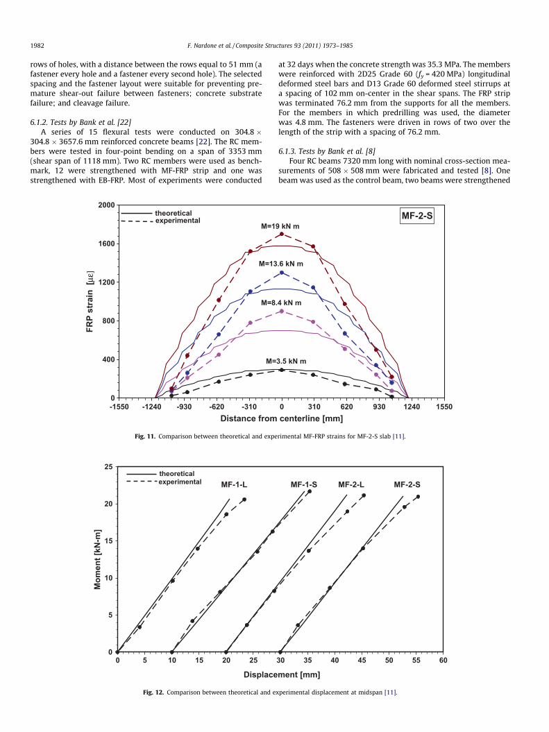
1982 F. Nardone et al. / Composite Structures 93 (2011) 1973–1985
rows of holes, with a distance between the rows equal to 51 mm (afastener every hole and a fastener every second hole). The selectedspacing and the fastener layout were suitable for preventing pre-mature shear-out failure between fasteners; concrete substratefailure; and cleavage failure.
6.1.2. Tests by Bank et al. [22]A series of 15 flexural tests were conducted on 304.8 �
304.8 � 3657.6 mm reinforced concrete beams [22]. The RC mem-bers were tested in four-point bending on a span of 3353 mm(shear span of 1118 mm). Two RC members were used as bench-mark, 12 were strengthened with MF-FRP strip and one wasstrengthened with EB-FRP. Most of experiments were conducted
0
400
800
1200
1600
2000
-1550 -1240 -930 -620 -310Distance from
FRP
stra
in [
με]
M=19
M=13
theoreticalexperimental
M=8.
M=
Fig. 11. Comparison between theoretical and expe
0
5
10
15
20
25
0 5 10 15 20 25
Displace
Mom
ent [
kN-m
]
theoreticalexperimental MF-1-L
Fig. 12. Comparison between theoretical and ex
at 32 days when the concrete strength was 35.3 MPa. The memberswere reinforced with 2D25 Grade 60 (fy = 420 MPa) longitudinaldeformed steel bars and D13 Grade 60 deformed steel stirrups ata spacing of 102 mm on-center in the shear spans. The FRP stripwas terminated 76.2 mm from the supports for all the members.For the members in which predrilling was used, the diameterwas 4.8 mm. The fasteners were driven in rows of two over thelength of the strip with a spacing of 76.2 mm.
6.1.3. Tests by Bank et al. [8]Four RC beams 7320 mm long with nominal cross-section mea-
surements of 508 � 508 mm were fabricated and tested [8]. Onebeam was used as the control beam, two beams were strengthened
MF-2-S
0 310 620 930 1240 1550 centerline [mm]
kN m
.6 kN m
4 kN m
3.5 kN m
rimental MF-FRP strains for MF-2-S slab [11].
30 35 40 45 50 55 60
ment [mm]
MF-2-SMF-2-LMF-1-S
perimental displacement at midspan [11].

F. Nardone et al. / Composite Structures 93 (2011) 1973–1985 1983
beam with two FRP strips fastened using galvanized steel andstainless steel fasteners, respectively. One beam was strengthenedwith three strips. The members were reinforced with 3D22 Grade60 deformed bars and D13 closed stirrups at 200 mm spacing. Onthe day of testing, the concrete strength was 34 MPa. In each strip,a single row of fasteners at 102 mm spacing along the length wasused. The members were tested under four-point bending over aspan of 6528 mm with a constant moment span of 762 mm.
6.2. Experimental vs. theoretical results at ultimate limit state (ULS)
In Table 1 a comparison between theoretical and experimentalvalues of moment, curvature and strain in the FRP are reported for
0
1000
2000
3000
0 200 400 600Distance from
FRP
stra
in [ μ
ε]
M=113 kN-m
M=136 kN-m
M=90 kN-m
M=68 kN-m
M=45 kN-m
M=23 kN-m
Fig. 13. Comparison between theoretical and experiment
0
500
1000
1500
2000
0 200 400 600 8Distance from
FRP
stra
in [ μ
ε]
M=90 kN-m
M=102 kN-m
M=79 kN-m
M=68 kN-m
M=45 kN-m
M=11 kN-m
Fig. 14. Comparison between theoretical and experimen
the ultimate limit state at the midspan of the tested members. Agood agreement has been obtained between the numerical predic-tions of maximum moment and experimental data, with amaximum underestimation equal to 15% and always on the con-servative side. In terms of ultimate curvature, the available straindata recorded at midspan for concrete and tensile steel wereadopted to evaluate the curvature of the cross-section. Napoli[11] reported all necessary data and the average underestimationwere evaluated to be about 30%. The predicted failure mode(MODE II) for all the specimens tested by Napoli [11] is concretecrushing as reported in the experimental observations.
A further comparison was performed in terms of FRP strainat midspan. The values at ultimate were reported for all the
H1.5-4-Y-AL47D-3-R
800 1000 1200 1400 1600 centerline [mm]
theoreticalexperimental
al MF-FRP strains for H1.5-4-Y-AL47D-3-R slab [22].
H1.0-4-Y-AL47D-5
00 1000 1200 1400 1600 centerline [mm]
theoreticalexperimental
tal MF-FRP strains for H1.0-4-Y-AL47D-5 slab [22].

1984 F. Nardone et al. / Composite Structures 93 (2011) 1973–1985
experimental programs, even if Napoli [11] reported that the max-imum FRP strain was not always found at midspan. The simplifiedanalytical model provided predictions quite close to the experi-mental outcomes and the average overestimation was about 10%.For specimens tested by Bank et al. [8,22], a satisfactory agreementwas obtained between theoretical and experimental FRP strains atbearing failure, with an average scatter equal to about 13%. Forthese specimens the maximum scatter between theoretical andexperimental ultimate moments was equal to 10%.
6.3. Experimental vs. theoretical results at serviceability limit state (SLS)
The suggested numerical model for serviceability limit statewas implemented to obtain FRP strain for different moment values
0
40
80
120
160
0 5 10 15Dispace
Mom
ent [
kN-m
]
theoreticalexperimental H1.5-4-Y-AL
Fig. 15. Comparison between theoretical and ex
0
50
100
150
200
250
0 500 1000FRP strain @
Mom
ent [
kN-m
]
experimentaltheoretical
Fig. 16. Comparison between theoretical and e
and to compare them with experimental data. The comparisonswere performed for flexural moments up to yielding of the steelonly for specimens where the experimental strain FRP-momentprofile was reported, otherwise the comparison was limitedto the midspan cross-section. A comparison between theoreticaland experimental displacements at midspan was alsoperformed.
Figs. 8–12 show the comparison between theoretical and exper-imental FRP strains and moment–midspan displacement for spec-imen tested by Napoli [11].
Figs. 13 and 14 show the FRP strain comparison of the strip forspecimens tested by Bank et al. [22]. For these specimens, the com-panion moment–midspan displacement curves are reported inFig. 15.
20 25 30 35 40ment [mm]
47D-3-R H1.0-4-Y-AL47D-5
perimental displacement at midspan [22].
1500 2000 2500 midspan [μμεε]
FRP 1 FRP2 SS
xperimental MF-FRP strain at midspan [8].

0
50
100
150
200
250
0 5 10 15 20 25 30 35 40 45 50Displacement [mm]
Mom
ent [
kN-m
]
theoreticalexperimental
FRP 1 FRP 2 SS FRP 3
Fig. 17. Comparison between theoretical and experimental displacement [8].
F. Nardone et al. / Composite Structures 93 (2011) 1973–1985 1985
Fig. 16 shows a comparison between FRP strain at midspan forslabs, tested by Bank et al. [8]. A comparison between moment–midspan displacement is reported in Fig. 17 for the specimenstested by Bank et al. [8].
7. Conclusions
The flexural behavior of RC members strengthened with MF-FRPstrips was discussed and procedures were proposed for the numer-ical analysis of the flexural behavior at both serviceability and ulti-mate limit states. In particular, the proposed models accountexplicitly for the slip between the substrate surface and the FRPstrip. Experimental tests available in the literature show three pos-sible failure modes for well-designed applications, namely: bearingfailure or net tension failure of the FRP laminate and concretecrushing. The model is capable of predicting these failure modes.The comparison between the analytical predictions and the exper-imental results shows a good agreement in terms of strain profilesin MF-FRP strips and moment deflection curves at serviceabilitylimit state. Similarly, comparison of nominal flexural capacity, ulti-mate curvature and FRP strain at ultimate limit state show goodagreement. The knowledge of the relationship between the forceacting on the fastener and the slip is fundamental in order to applythe proposed model and more research to address this fundamen-tal parameter is needed.
Acknowledgements
The authors acknowledge the financial support provided by theNSF Industry/University Cooperative Research Center ‘‘CICI’’ and itsindustry members.
References
[1] ACI 440.2R-08. Guide for the design and construction of externally bonded FRPsystems for strengthening concrete structures. Farmington Hills, MI: AmericanConcrete Institute; 2008.
[2] fib (Fédération Internationale du Béton). Externally bonded FRP reinforcementfor RC Structures. Switzerland: International Federation for Structural Concrete(fib); 2001.
[3] CNR-DT 200. Guide for the design and construction of externally bonded FRPsystems for strengthening existing structures. Roma, IT: National ResearchCouncil; 2004.
[4] Bank LC. Mechanically fastened FRP (MF-FRP) - a viable alternative forstrengthening RC members. In: Proc. FRP composites in civil engineering,Adelaide, AU: CICE; 2004. p. 3–15.
[5] Rizzo A. Application of mechanically fastened FRP (MF-FRP)-pre-curedlaminates in off-system bridges. M.S. thesis. University of Missouri-Rolla;2005.
[6] Rizzo A, Galati N, Nanni A, Dharani LR. Material characterization of FRPpre-cured laminates used in the mechanically fastened FRP strengtheningof RC structures. In: Proc FRPRCS-7, New Orleans, USA, vol. 230; 2005.p. 135–52.
[7] Rizzo A, Galati N, Nanni, A, Bank LC. Strengthening concrete structures withmechanically fastened pultruded strips. In: Proc. composites, Columbus, Ohio;2005.
[8] Bank LC, Oliva MG, Arora D, Borowicz DT. Rapid strengthening of reinforcedconcrete bridges. Wisconsin highway research program. Report no. 03–06.Madison, WI: Wisconsin Department of Transportation; 2003.
[9] Lamanna AJ, Bank LC, Scott DW. Flexural strengthening of reinforced concretemembers by mechanically attaching fiber-reinforced polymer strips. J ComposConstruct 2004;8(3):203–10.
[10] Lee JH, Lopez MM, Bakis CE. Slip effects in reinforced concrete members withmechanically fastened FRP strip. Cem Concr Compos 2009;31:496–504.
[11] Napoli A. RC structures strengthened with mechanically fastened FRP systems.M.S. thesis. University of Miami-Coral Gables, FL; 2008.
[12] Bank LC, Arora D. Analysis of RC beams strengthened with mechanicallyfastened FRP (MF-FRP) strips. J Compos Struct 2007;79:180–91.
[13] ASTM D5961/D 5961M. Standard test method for bearing response of polymermatrix composite laminates. American West Conshohocken, PA: Society forTesting and Materials; 2005.
[14] Elsayed WE, Ebead UA, Neale KW. Studies on mechanically fastenedfiber-reinforced polymer strengthening systems. ACI Struct J2009;106(1):49–59.
[15] Rosner CN, Rizkalla SH. Bolted connections for fiber-reinforced compositestructural members: experimental program. J Mater Civil Eng1995;7(4):223–31.
[16] Godwin EW, Matthews FL. A review of the strength of joints in fibre-reinforcedplastics: part 1. Mechanically fastened joints. Composites 1980:155–60.
[17] Arora D. Rapid strengthening of reinforced concrete bridge with mechanicallyfastened-fiber reinforced polymer strips. M.S. thesis. University of Wisconsin-Madison; 2003.
[18] Comancho PP, Matthews FL. Stress analysis and strength prediction ofmechanically fastened joints in FRP: a review. Composites Part A1997;28:529–47.
[19] Lamanna AJ. Flexural strengthening of reinforced concrete beams withmechanically fastened fiber reinforced polymer Strips. PhD thesis. Universityof Wisconsin-Madison; 2002.
[20] ACI 318.M-08. Building code requirements for structural. Farmington Hills, MI:American Concrete Institute; 2008.
[21] Fabbrocino G, Manfredi G, Cosenza E. Non linear analysis of composite beamsunder positive bending moment. Comput Struct 1999;70:77–89.
[22] Bank LC, Lamanna AJ, Ray JC, Velazquez GI. Rapid strengthening of reinforcedconcrete members with mechanically fastened, fiber-reinforced polymericcomposite materials. US Army Corps of Engineers, Report number ERDC/GSLTR-02-4; 2002.
Related Documents


