Abstract- We have proposed a unified approach to the modeling and study of developments in the field of Nanotechnology and its application in futuristic Nano-enabled Cells. The necessity of a nonporous membrane has been eminent in recent fuel cells. The need for MEMS based models for porous silicon based membranes based on nano imprints technology has been met by modeling it in SUGAR in MATLAB environment. We have identified and categorized the domains of Nano enabled solar cells and have put forth a proposition for multi scale modeling of Solar cells. Multi scale modeling on HPC (High performance computing) of a Nano enabled solar cell is shown under MCCS (Microsoft compute cluster environment) environment using extreme optimization numerical library is implemented. Distribution and performance analysis of four levels of computation in a multi scale model is implemented with the distribution being carried out from classical semi-conductor to quantum levels as to accurately predict the behavior and properties of the solar cell as per the needs of the engineering of devices. I. INTRODUCTION rowing concerns of climate change concomitant with the escalation in oil prices, peak oil and increasing support in the Government and private sector are driving increasing alternative and renewable energy legislations, mounting up of incentives and commercialization of this technology. Solar cell and fuel cell technology provide us with the ideal alternative in this energy-driven age. Fuel cell technology has seen a rapid growth in recent years. Due to the developments in Nanotechnology and their application in fuel cell technology and solar cells, newer methodologies are being developed. The penetration of the market dominated by today’s bulky batteries is only possible with the paradigm of nanotechnology. The ultimate aim is to minimize and shrink down the size of fuel cells using nanotechnology and MEMS. Application of MEMS in a MEMS based Fuel cell has been shown in Fig. 1. Solar cells are the most promising technology for green and clean energy. Futuristic models of solar cells will use advanced nanomaterials for increasing efficiency and reliability of solar cells [13]. Quantum dots based solar harvesting architecture has been discussed [1]. Photo voltaic effects of a PbSe nanocrystal quantum dots based photo diode has been studied [5]. Quantum Well Multi junction solar cells have been discussed that describe the growth and testing of thin layers of AlGaAs-GaAs [3]. Thus the quantum mechanical behavior of the solar cell needs to be taken into consideration while modeling it. Hence the application of such solar cells depends upon its various quantum physical behaviors. Solar cell integration with autonomous sensor networks and their powering has been discussed [2]. Fig. 1. MEMS based fuel Cell. II. MODELING MEMS BASED FUEL CELLS DMFC (Direct Methanol Fuel Cell) has benefited maximum from progression in MEMS technologies in bringing about advances in its existing framework. MEMS based fuel cell system has been proposed where the power density was stated to be 220 mW/cm 2 when the potential was 0.65 V thereby showing the advantages of integration of MEMS based devices in fuel cell technology [6]. Fuel cells have been the favorite candidates for portable electronics where indirect hydrogen, direct methanol and Nanotechnology based fuel cells have been of prime focus [8]. The relationship between energy content and respective fuel volume used is shown in Fig. 2. Higher density, lower form factor and minimization of cost have remained the prime focus for fuel cells. Key requirements of micro fuel cell system for portable electronics incorporating MEMS technologies have been conferred and are being developed at Motorola TM [9]. Development of hydrogen fuel cell cycle has been discussed from a thermo dynamical perspective and the challenges that exist for transformation from a fossil-fuel based economy to a hydrogen based economy have been stated. Also historical aspects in fuel-cell technology have been conversed [10]. Various methods for generation of energy for portable devices including fuel cell technology as a practical solution and hybrid of various technologies including like piezoelectric, photo voltaic are Modeling Nano Enabled Elements of Solar and Fuel Cell Rohit Pathak, Satyadhar Joshi, Pawan Kotak, Salman Ahmed, and Virendra Verma G Manuscript received April 15, 2009. Rohit Pathak is with the Computer Science Department, Acropolis Institute of Technology & Research, Indore, M.P., India (e-mail: [email protected]) Satyadhar Joshi is with the Electronics & Electrical Dept., Shri Vaishnav Institute of Technology & Science, Indore, M.P., India (e-mail: [email protected]) Pawan Kotak is with the Electronics & Communication Department, Acropolis Institute of Technology & Research, Indore, M.P., India (e- mail: [email protected]) Salman Ahmed is with the Electronics & Electrical Dept., Shri Vaishnav Institute of Technology & Science, Indore, M.P., India (e-mail: [email protected]) Virendra Verma is with the Electronics & Communication Dept., Shri Venkateshwar Institute of Technology, Indore, M.P., India (e-mail: virendra_verma5@yahoo.com) 2009 Conference on Innovative Technologies in Intelligent Systems and Industrial Applications (CITISIA 2009) Monash University, Sunway campus, Malaysia, 25th & 26th July 2009. 978-1-4244-2887-8/09/$25.00 ©2009 IEEE 281 Kindly cite the paper, presentation or any other work you refer; this work is indexed in IEEE Xplore DL. Say no to Plagiarism.

Welcome message from author
This document is posted to help you gain knowledge. Please leave a comment to let me know what you think about it! Share it to your friends and learn new things together.
Transcript
Abstract- We have proposed a unified approach to the modeling and study of developments in the field of Nanotechnology and its application in futuristic Nano-enabled Cells. The necessity of a nonporous membrane has been eminent in recent fuel cells. The need for MEMS based models for porous silicon based membranes based on nano imprints technology has been met by modeling it in SUGAR in MATLAB environment. We have identified and categorized the domains of Nano enabled solar cells and have put forth a proposition for multi scale modeling of Solar cells. Multi scale modeling on HPC (High performance computing) of a Nano enabled solar cell is shown under MCCS (Microsoft compute cluster environment) environment using extreme optimization numerical library is implemented. Distribution and performance analysis of four levels of computation in a multi scale model is implemented with the distribution being carried out from classical semi-conductor to quantum levels as to accurately predict the behavior and properties of the solar cell as per the needs of the engineering of devices.
I. INTRODUCTION
rowing concerns of climate change concomitant with the escalation in oil prices, peak oil and increasing support in the Government and private
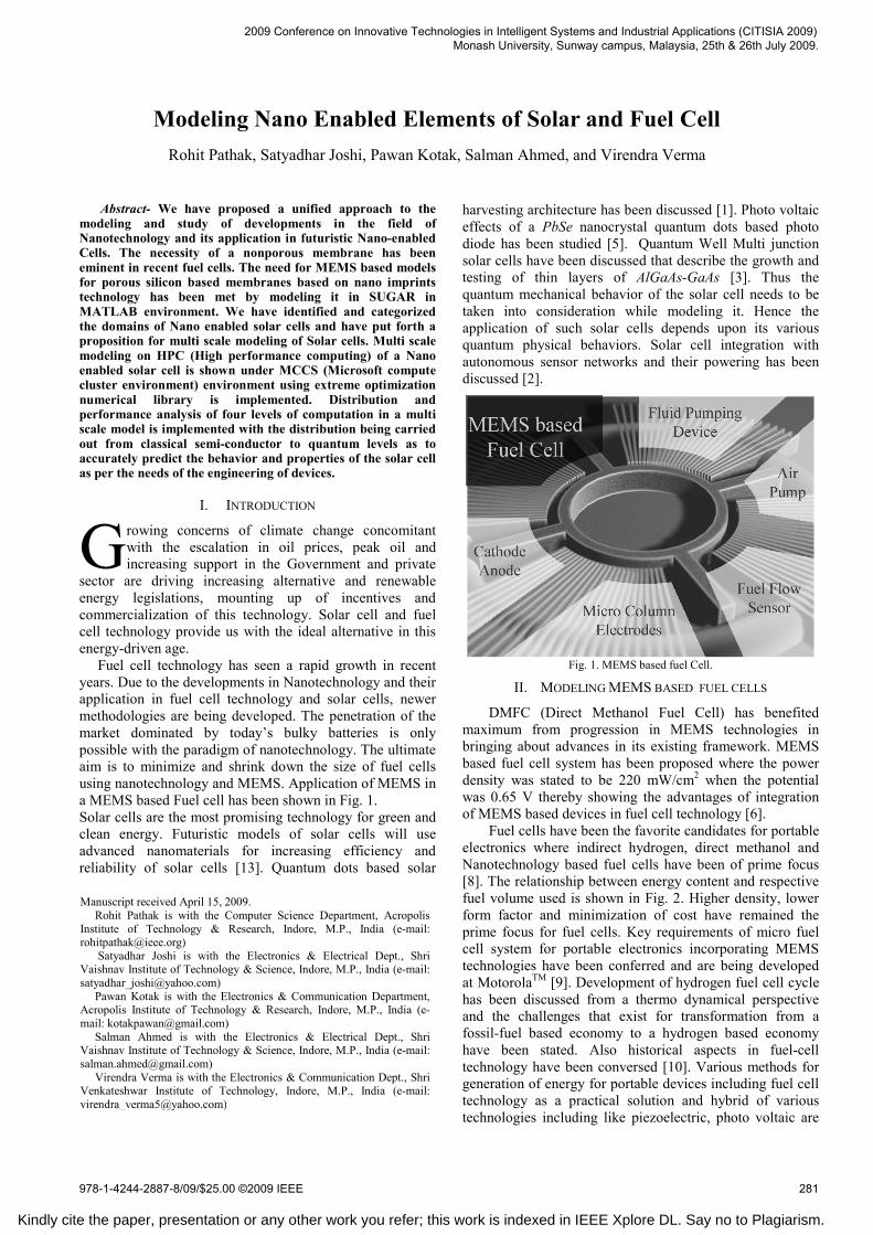
sector are driving increasing alternative and renewable energy legislations, mounting up of incentives and commercialization of this technology. Solar cell and fuel cell technology provide us with the ideal alternative in this energy-driven age. Fuel cell technology has seen a rapid growth in recent years. Due to the developments in Nanotechnology and their application in fuel cell technology and solar cells, newer methodologies are being developed. The penetration of the market dominated by today’s bulky batteries is only possible with the paradigm of nanotechnology. The ultimate aim is to minimize and shrink down the size of fuel cells using nanotechnology and MEMS. Application of MEMS in a MEMS based Fuel cell has been shown in Fig. 1. Solar cells are the most promising technology for green and clean energy. Futuristic models of solar cells will use advanced nanomaterials for increasing efficiency and reliability of solar cells [13]. Quantum dots based solar
harvesting architecture has been discussed [1]. Photo voltaic effects of a PbSe nanocrystal quantum dots based photo diode has been studied [5]. Quantum Well Multi junction solar cells have been discussed that describe the growth and testing of thin layers of AlGaAs-GaAs [3]. Thus the quantum mechanical behavior of the solar cell needs to be taken into consideration while modeling it. Hence the application of such solar cells depends upon its various quantum physical behaviors. Solar cell integration with autonomous sensor networks and their powering has been discussed [2].
Fig. 1. MEMS based fuel Cell.
II. MODELING MEMS BASED FUEL CELLS
DMFC (Direct Methanol Fuel Cell) has benefited maximum from progression in MEMS technologies in bringing about advances in its existing framework. MEMS based fuel cell system has been proposed where the power density was stated to be 220 mW/cm2 when the potential was 0.65 V thereby showing the advantages of integration of MEMS based devices in fuel cell technology [6].
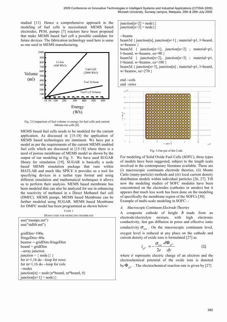
Fuel cells have been the favorite candidates for portable electronics where indirect hydrogen, direct methanol and Nanotechnology based fuel cells have been of prime focus [8]. The relationship between energy content and respective fuel volume used is shown in Fig. 2. Higher density, lower form factor and minimization of cost have remained the prime focus for fuel cells. Key requirements of micro fuel cell system for portable electronics incorporating MEMS technologies have been conferred and are being developed at MotorolaTM [9]. Development of hydrogen fuel cell cycle has been discussed from a thermo dynamical perspective and the challenges that exist for transformation from a fossil-fuel based economy to a hydrogen based economy have been stated. Also historical aspects in fuel-cell technology have been conversed [10]. Various methods for generation of energy for portable devices including fuel cell technology as a practical solution and hybrid of various technologies including like piezoelectric, photo voltaic are
Modeling Nano Enabled Elements of Solar and Fuel Cell Rohit Pathak, Satyadhar Joshi, Pawan Kotak, Salman Ahmed, and Virendra Verma
G
Manuscript received April 15, 2009. Rohit Pathak is with the Computer Science Department, Acropolis
Institute of Technology & Research, Indore, M.P., India (e-mail: [email protected])
Satyadhar Joshi is with the Electronics & Electrical Dept., Shri Vaishnav Institute of Technology & Science, Indore, M.P., India (e-mail: [email protected])
Pawan Kotak is with the Electronics & Communication Department, Acropolis Institute of Technology & Research, Indore, M.P., India (e-mail: [email protected])
Salman Ahmed is with the Electronics & Electrical Dept., Shri Vaishnav Institute of Technology & Science, Indore, M.P., India (e-mail: [email protected])
Virendra Verma is with the Electronics & Communication Dept., Shri Venkateshwar Institute of Technology, Indore, M.P., India (e-mail: [email protected])
2009 Conference on Innovative Technologies in Intelligent Systems and Industrial Applications (CITISIA 2009) Monash University, Sunway campus, Malaysia, 25th & 26th July 2009.
978-1-4244-2887-8/09/$25.00 ©2009 IEEE 281
Kindly cite the paper, presentation or any other work you refer; this work is indexed in IEEE Xplore DL. Say no to Plagiarism.
studied [11]. Hence a comprehensive approach in the modeling of fuel cells is necessitated. MEMS based electrodes, PEM, pumps [7] reactors have been proposed that make MEMS based fuel cell a possible candidate for future devices. The fabrication technology used here is same as one used in MEMS manufacturing.
Fig. 2.Comparison of fuel volume vs energy for fuel cells and current
lithium-ion cells [8].
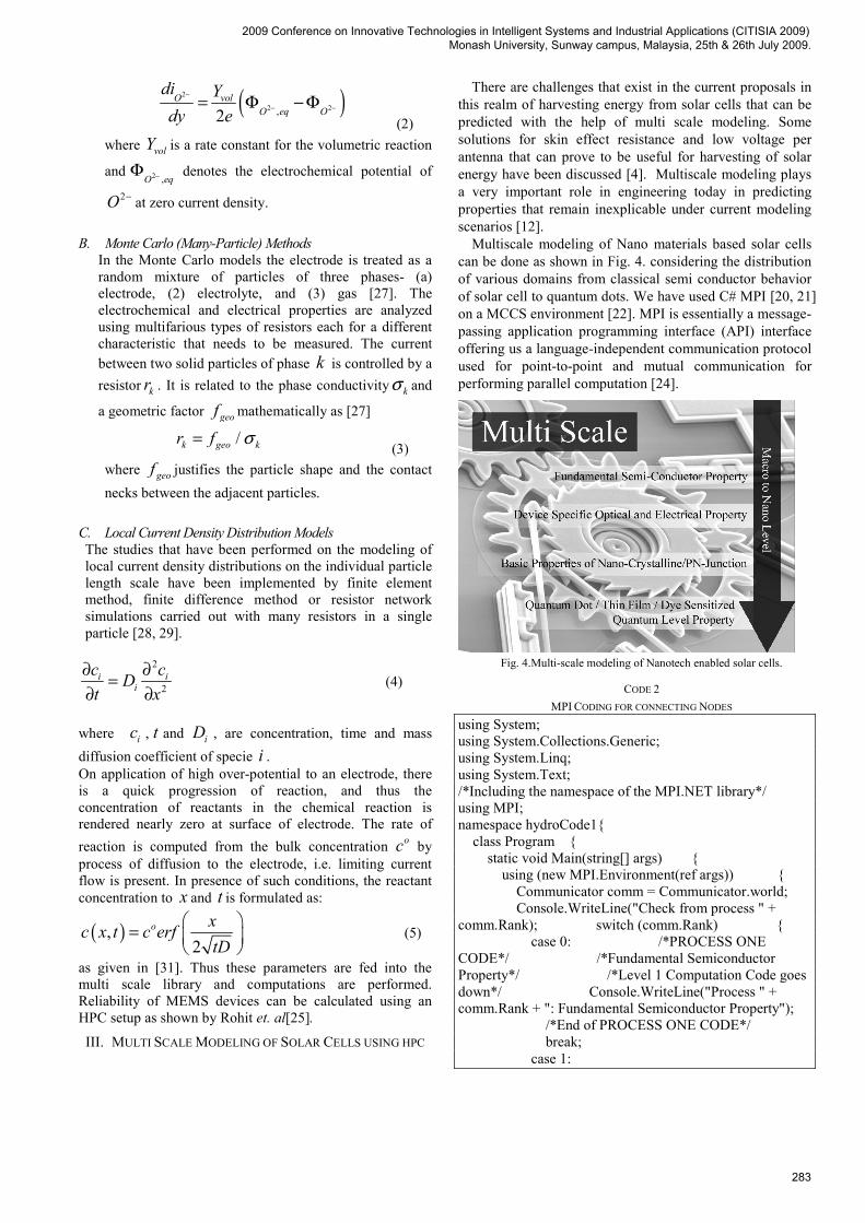
MEMS based fuel cells needs to be modeled for the current application. As discussed in [15-18] the application of MEMS based technologies are imminent. We have put a model as per the requirements of the current MEMS enabled fuel cells which are discussed in [15-18] where there is a need of porous membrane of MEMS model as shown by the output of our modeling in Fig. 5. We have used SUGAR library for simulation [19]. SUGAR is basically a node based MEMS simulation package that runs within MATLAB and much like SPICE it provides us a tool for specifying devices in a netlist type format and using different simulation and mathematical techniques it allows us to perform their analysis. MEMS based membrane has been modeled that can also be analyzed for use in enhancing the reactivity of methanol in a Direct Methanol fuel cell (DMFC). MEMS pumps, MEMS based Membrane can be further modeled using SUGAR. MEMS based Membrane for DMFC model has been programmed as shown below:
CODE 1 DEMO CODE FOR MODELING MEMBRANE
use("mumps.net") use("stdlib.net") gridDim=100u fringeDim=40u beamw = gridDim-fringeDim beaml = gridDim --array junction junction = { node{} } for n=1,16 do --loop for rows for m=1,16 do --loop for cols --nodes junction[n] = node{n*beaml, m*beaml, 0} junction[n+1] = node{}
junction[n+2] = node{} junction[n+3] = node{} --beams beam3d { junction[n], junction[n+1] ; material=p1, l=beaml, w=beamw } beam3d { junction[n+1], junction[n+2] ; material=p1, l=beaml, w=beamw, oz=90 } beam3d { junction[n+2], junction[n+3] ; material=p1, l=beaml, w=beamw, oz=180 } beam3d { junction[n+3], junction[n] ; material=p1, l=beaml, w=beamw, oz=270 } end --cols end –rows
Fig. 3.Out put of the Code.
For modeling of Solid Oxide Fuel Cells (SOFC), three types of models have been suggested, subject to the length scale involved in the contemporary literature available. These are (i) macroscopic continuum electrode theories, (ii) Monte Carlo (many-particle) methods and (iii) local current density distribution models within individual particles [26, 27]. Till now the modeling studies of SOFC modules have been concentrated on the electrodes (cathodes or anodes) but it appears that much less work has been done on the modeling of specifically the membrane region of the SOFCs [30]. Example of multi-scale modeling in SOFC: -
A. Macroscopic Continuum Electrode Theories A composite cathode of height h made from an electrode/electrolyte mixture, with high electronic conductivity, fast gas diffusion in pores and effective ionic conductivity ionσ . On the macroscopic continuum level, oxygen level is reduced at any place on the cathode and current density of oxide ions is formulated [27] as
2
2 2ion O
O
di
e dyσ −
−
Φ= − (1)
where e represents electric charge of an electron and the electrochemical potential of the oxide ions is denoted by 2O −Φ . The electrochemical reaction rate is given by [27]
2009 Conference on Innovative Technologies in Intelligent Systems and Industrial Applications (CITISIA 2009) Monash University, Sunway campus, Malaysia, 25th & 26th July 2009.
282
( )2
2 2,2O vol
O eq O
di Ydy e
−
− −= Φ − Φ (2)
where volY is a rate constant for the volumetric reaction
and 2 ,O eq−Φ denotes the electrochemical potential of
2O − at zero current density.
B. Monte Carlo (Many-Particle) Methods In the Monte Carlo models the electrode is treated as a random mixture of particles of three phases- (a) electrode, (2) electrolyte, and (3) gas [27]. The electrochemical and electrical properties are analyzed using multifarious types of resistors each for a different characteristic that needs to be measured. The current between two solid particles of phase k is controlled by a resistor kr . It is related to the phase conductivity kσ and
a geometric factor geof mathematically as [27]
/k geo kr f σ= (3)
where geof justifies the particle shape and the contact necks between the adjacent particles.
C. Local Current Density Distribution Models The studies that have been performed on the modeling of local current density distributions on the individual particle length scale have been implemented by finite element method, finite difference method or resistor network simulations carried out with many resistors in a single particle [28, 29].
2
2i i
ic cDt x
∂ ∂=∂ ∂
(4)
where ic , t and iD , are concentration, time and mass diffusion coefficient of specie i . On application of high over-potential to an electrode, there is a quick progression of reaction, and thus the concentration of reactants in the chemical reaction is rendered nearly zero at surface of electrode. The rate of reaction is computed from the bulk concentration oc by process of diffusion to the electrode, i.e. limiting current flow is present. In presence of such conditions, the reactant concentration to x and t is formulated as:
( ),2
o xc x t c erftD
⎛ ⎞= ⎜ ⎟⎝ ⎠
(5)
as given in [31]. Thus these parameters are fed into the multi scale library and computations are performed. Reliability of MEMS devices can be calculated using an HPC setup as shown by Rohit et. al[25].
III. MULTI SCALE MODELING OF SOLAR CELLS USING HPC
There are challenges that exist in the current proposals in this realm of harvesting energy from solar cells that can be predicted with the help of multi scale modeling. Some solutions for skin effect resistance and low voltage per antenna that can prove to be useful for harvesting of solar energy have been discussed [4]. Multiscale modeling plays a very important role in engineering today in predicting properties that remain inexplicable under current modeling scenarios [12].
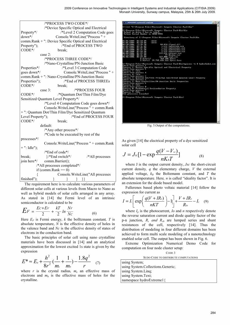
Multiscale modeling of Nano materials based solar cells can be done as shown in Fig. 4. considering the distribution of various domains from classical semi conductor behavior of solar cell to quantum dots. We have used C# MPI [20, 21] on a MCCS environment [22]. MPI is essentially a message-passing application programming interface (API) interface offering us a language-independent communication protocol used for point-to-point and mutual communication for performing parallel computation [24].
Fig. 4.Multi-scale modeling of Nanotech enabled solar cells.
CODE 2 MPI CODING FOR CONNECTING NODES
using System; using System.Collections.Generic; using System.Linq; using System.Text; /*Including the namespace of the MPI.NET library*/ using MPI; namespace hydroCode1{ class Program { static void Main(string[] args) { using (new MPI.Environment(ref args)) { Communicator comm = Communicator.world; Console.WriteLine("Check from process " + comm.Rank); switch (comm.Rank) { case 0: /*PROCESS ONE CODE*/ /*Fundamental Semiconductor Property*/ /*Level 1 Computation Code goes down*/ Console.WriteLine("Process " + comm.Rank + ": Fundamental Semiconductor Property"); /*End of PROCESS ONE CODE*/ break; case 1:
2009 Conference on Innovative Technologies in Intelligent Systems and Industrial Applications (CITISIA 2009) Monash University, Sunway campus, Malaysia, 25th & 26th July 2009.
283
/*PROCESS TWO CODE*/ /*Device Specific Optical and Electrical Property*/ /*Level 2 Computation Code goes down*/ Console.WriteLine("Process " + comm.Rank + ": Device Specific Optical and Electrical Property"); /*End of PROCESS TWO CODE*/ break; case 2: /*PROCESS THREE CODE*/ /*Nano-Crystalline/PN-Junction Basic Properties*/ /*Level 3 Computation Code goes down*/ Console.WriteLine("Process " + comm.Rank + ": Nano-Crystalline/PN-Junction Basic Properties"); /*End of PROCESS THREEs CODE*/ break; case 3: /*PROCESS FOUR CODE*/ /*Quantum Dot/Thin Film/Dye Sensitized Quantum Level Property*/ /*Level 4 Computation Code goes down*/ Console.WriteLine("Process " + comm.Rank + ": Quantum Dot/Thin Film/Dye Sensitized Quantum Level Property"); /*End of PROCESS FOUR CODE*/ break; default: /*Any other process*/ /*Code to be executed by rest of the processes*/ Console.WriteLine("Process " + comm.Rank + ": Idle"); /*End of code*/ break; }/*End switch*/ /*All processes join here*/ comm.Barrier(); /*All processes completed*/ if (comm.Rank == 0) { Console.WriteLine("All processes finished"); } } } }}
The requirement here is to calculate various parameters of different solar cells at various levels from Macro to Nano as well as hybrid models of solar cells arranged in any array. As stated in [14] the Fermi level of an intrinsic semiconductor is calculated to be
2 2C V V
C
E E kT NF ln NE +
= + (6) Here EF is Fermi energy, k the bolltzmann constant, T is absolute temperature, N is the effective density of holes in the valence band and Nc is the effective density of states of electrons in the conduction band.
The basic principles of solar cell using nano crystalline materials have been discussed in [14] and an analytical approximation for the lowest excited 1s state is given by the expression
2 2
2
1 1 1.8* ( )8
g
e h
h qE Er m m r
≈ + + − (7)
where r is the crystal radius, me an effective mass of electrons and mh is the effective mass of holes for the crystalline.
Fig. 5.Output of the computations.
As given [14] the electrical property of a dye sensitized solar cell
( )[1 exp ]ocSC
B
q V VJ JnK T
−= − (8)
where J is the output current density, Jsc the short-circuit current density, q the elementary charge, V the external applied voltage, kB the Boltzmann constant, and T the absolute temperature. Here, n is called “ideality factor”. It is an extension for the diode based model.
Fullerenes based photo voltaic material [14] follow the expression for current as
( )exp 1S So p
Sh
q V IR V IRI I InKT R
⎡ + ⎤ +⎛ ⎞= − + −⎜ ⎟⎢ ⎥⎝ ⎠⎣ ⎦ (9)
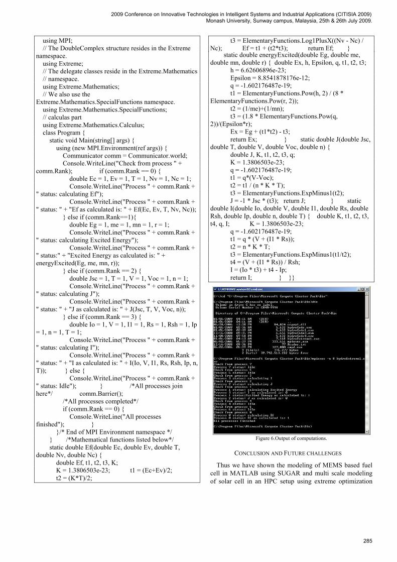
where Ip is the photocurrent, Io and n respectively denote the reverse saturation current and diode quality factor of the p-n junction, Rs and Rsh are lumped series and shunt resistances of the cell, respectively [14]. Thus the distribution of modeling in four different domains has been achieved to form multi scale modeling of a nanotechnology enabled solar cell. The output has been shown in Fig. 6.
Extreme Optimization Numerical Demo Code for computation on four node cluster setup:
CODE 3 SUDO CODE TO DISTRIBUTE COMPUTATIONS
using System; using System.Collections.Generic; using System.Linq; using System.Text; namespace hydroExtreme1{
2009 Conference on Innovative Technologies in Intelligent Systems and Industrial Applications (CITISIA 2009) Monash University, Sunway campus, Malaysia, 25th & 26th July 2009.
284
using MPI; // The DoubleComplex structure resides in the Extreme namespace. using Extreme; // The delegate classes reside in the Extreme.Mathematics // namespace. using Extreme.Mathematics; // We also use the Extreme.Mathematics.SpecialFunctions namespace. using Extreme.Mathematics.SpecialFunctions; // calculas part using Extreme.Mathematics.Calculus; class Program { static void Main(string[] args) { using (new MPI.Environment(ref args)) { Communicator comm = Communicator.world; Console.WriteLine("Check from process " + comm.Rank); if (comm.Rank == 0) { double Ec = 1, Ev = 1, T = 1, Nv = 1, Nc = 1; Console.WriteLine("Process " + comm.Rank + " status: calculating Ef"); Console.WriteLine("Process " + comm.Rank + " status: " + "Ef as calculated is: " + Ef(Ec, Ev, T, Nv, Nc)); } else if (comm.Rank==1){ double Eg = 1, me = 1, mn = 1, r = 1; Console.WriteLine("Process " + comm.Rank + " status: calculating Excited Energy"); Console.WriteLine("Process " + comm.Rank + " status:" + "Excited Energy as calculated is: " + energyExcited(Eg, me, mn, r)); } else if (comm.Rank == 2) { double Jsc = 1, T = 1, V = 1, Voc = 1, n = 1; Console.WriteLine("Process " + comm.Rank + " status: calculating J"); Console.WriteLine("Process " + comm.Rank + " status: " + "J as calculated is: " + J(Jsc, T, V, Voc, n)); } else if (comm.Rank == 3) { double Io = 1, V = 1, I1 = 1, Rs = 1, Rsh = 1, Ip = 1, n = 1, T = 1; Console.WriteLine("Process " + comm.Rank + " status: calculating I"); Console.WriteLine("Process " + comm.Rank + " status: " + "I as calculated is: " + I(Io, V, I1, Rs, Rsh, Ip, n, T)); } else { Console.WriteLine("Process " + comm.Rank + " status: Idle"); } /*All processes join here*/ comm.Barrier(); /*All processes completed*/ if (comm.Rank == 0) { Console.WriteLine("All processes finished"); } }/* End of MPI Environment namespace */ } /*Mathematical functions listed below*/ static double Ef(double Ec, double Ev, double T, double Nv, double Nc) { double Ef, t1, t2, t3, K; K = 1.3806503e-23; t1 = (Ec+Ev)/2; t2 = (K*T)/2;
t3 = ElementaryFunctions.Log1PlusX((Nv - Nc) / Nc); Ef = t1 + (t2*t3); return Ef; } static double energyExcited(double Eg, double me, double mn, double r) { double Ex, h, Epsilon, q, t1, t2, t3; h = 6.62606896e-23; Epsilon = 8.8541878176e-12; q = -1.602176487e-19; t1 = ElementaryFunctions.Pow(h, 2) / (8 * ElementaryFunctions.Pow(r, 2)); t2 = (1/me)+(1/mn); t3 = (1.8 * ElementaryFunctions.Pow(q, 2))/(Epsilon*r); Ex = Eg + (t1*t2) - t3; return Ex; } static double J(double Jsc, double T, double V, double Voc, double n) { double J, K, t1, t2, t3, q; K = 1.3806503e-23; q = -1.602176487e-19; t1 = q*(V-Voc); t2 = t1 / (n * K * T); t3 = ElementaryFunctions.ExpMinus1(t2); J = -1 * Jsc * (t3); return J; } static double I(double Io, double V, double I1, double Rs, double Rsh, double Ip, double n, double T) { double K, t1, t2, t3, t4, q, I; K = 1.3806503e-23; q = -1.602176487e-19; t1 = q * (V + (I1 * Rs)); t2 = n * K * T; t3 = ElementaryFunctions.ExpMinus1(t1/t2); t4 = (V + (I1 * Rs)) / Rsh; I = (Io * t3) + t4 - Ip; return I; } }}
Figure 6.Output of computations.
CONCLUSION AND FUTURE CHALLENGES
Thus we have shown the modeling of MEMS based fuel cell in MATLAB using SUGAR and multi scale modeling of solar cell in an HPC setup using extreme optimization
2009 Conference on Innovative Technologies in Intelligent Systems and Industrial Applications (CITISIA 2009) Monash University, Sunway campus, Malaysia, 25th & 26th July 2009.
285
library under MCCS environment. Simplified parametric values have been assumed in the computations to generate the output. SUGAR modeling of a DMFC is programmed in code 1. The output is a MEMS based membrane as illustrated in Fig. 3. MPI program code has been executed in code 2 and the respective output is shown in Fig. 2. And finally programming code for an extreme optimization numerical demo on a four node cluster setup has been achieved, as exemplified by Fig. 3. We have carried out and executed the distribution process of the jobs in an HPC setup has been and the modeling of certain aspects of solar cells which has been shown in Fig. 6. A MEMS based membrane that can help in modeling of MEMS based cells of [15-18] and provide acceleration to research in this field. Nanotechnology and MEMS enabled solar and fuel cells will have optimum characteristics. This was done as part of Project [23]. Future commercialization of such solar and fuel cell will see greater use in diversified areas. Portable fuel cells will see the replacement of contemporary bulky battery technology. The cost of solar cells will decrease and their efficiency will increase significantly in the future via the use of these techniques.
REFERENCES [1] Wakayama, C.; Kohn, W.; Zabinsky, Z.; Shi, R., “A quantum-dot
light-harvesting architecture using deterministic phase control,” IEEE International Symposium on Circuits and Systems, 2008, ISCAS 2008, pp. 332 – 335, 18-21 May 2008, DOI=10.1109/ISCAS.2008.4541422
[2] Perlaky, G.; Mezosi, G.; Zolomy, I., “Sensor powering with integrated MOS compatible solar cell array,” IEEE Design and Diagnostics of Electronic Circuits and systems, pp. 251 – 253, 2006, DOI=10.1109/DDECS.2006.1649630
[3] Kevin Clark; Eduardo Maldonado; Robert T. Bate; Wiley P. Kirk, “ZnBeTe Buffer Layers for AlGaAs-GaAs Quantum Well Solar Cell Junctions Epitaxially Integrated on Silicon,” IEEE 4th World Conference on Photovoltaic Energy Conversion, Conference Record of the 2006, Volume 1, pp. 56 – 58, May 2006, DOI=10.1109/WCPEC.2006.279345
[4] Sarehraz, M.; Buckle, K.; Weller, T.; Stefanakos, E.; Bhansali, S.; Goswami, Y.; Subramanian Krishnan, “Rectenna developments for solar energy collection,” Conference Record of the Thirty-first IEEE Photovoltaic Specialists Conference, 2005, pp. 78 – 81, 3-7 Jan. 2005
[5] Cui, D.; Jian Xu; Sheng-Yong Xu; Paradee, G.; Lewis, B.A.; Gerhold, M.D., “Infrared photodiode based on colloidal PbSe nanocrystal quantum dots,” IEEE Transactions on Nanotechnology, Volume 5, Issue 4, pp. 362 – 367, July 2006, DOI=10.1109/TNANO.2006.877432
[6] Kim, T.; Kwon, S., “MEMS fuel cell system for portable power source: Integration of methanol reformer, PROX, and fuel cell,” IEEE 21st International Conference on Micro Electro Mechanical Systems, 2008. MEMS 2008, pp. 980 – 983, 13-17 Jan. 2008, DOI=10.1109/MEMSYS.2008.4443822
[7] Jaewon Chung; Grigoropoulos, C.P.; Greif, R., “Infrared thermal velocimetry in MEMS-based fluidic devices,” Journal of Microelectromechanical Systems, Volume 12, Issue 3, pp. 365 – 372, June 2003, DOI=10.1109/JMEMS.2003.811753
[8] Dyer, C.K., “Fuel cells and portable electronics,” Symposium on VLSI Circuits, 2004. Digest of Technical Papers. 2004, pp. 124 – 127, 17-19 June 2004
[9] Xie, C. Pavio, J. Hallmark, J. Bostaph, J. Fisher, A. , “Key requirements of micro fuel cell system for portable electronics,” 37th Intersociety Energy Conversion Engineering Conference, 2002. IECEC '02. 2002, pp. 603- 606, 29-31 July 2004
[10] Scott, J.H., “The Development of Fuel Cell Technology for Electric Power Generation: From NASAapos;s Manned Space Program to the "Hydrogen Economy" ,” Proceedings of the IEEE, Volume 94, Issue 10, pp. 1815 – 1825, Oct. 2006, DOI=10.1109/JPROC.2006.883702
[11] Robion, A.; Sadarnac, D.; Lanzetta, F.; Marquet, D.; Rivera, T., “Breakthrough in energy generation for mobile or portable devices,” 29th International Telecommunications Energy Conference, 2007. INTELEC 2007, pp. 460 – 466, Sept. 30 2007-Oct. 4 2007, DOI=10.1109/INTLEC.2007.4448821
[12] Engquist, Björn; Lötstedt, Per; Runborg, Olof vol 44 Multiscale Methods In Science And Engineering New York: Springer, 2005 pp
[13] Manna, T.K. Mahajan, S.M., “Nanotechnology in the Development of Photovoltaic Cells,” International Conference on Clean Electrical Power, 2007. ICCEP '07. pp. 379-386, 21-23 May 2007, DOI=10.1109/ICCEP.2007.384240
[14] Tetsuo Soga, Nanostructured Materials for Solar Energy Conversion Amsterdam: Elsevier 2006 pp 5-6, 36-37, 90-91, 382-383
[15] Kuan-Lun Chu Gold, S. Subramanian, V. Chang Lu Shannon, M.A. Masel, R.I., “A nanoporous silicon membrane electrode assembly for on-chip micro fuel cell applications,” Journal of Microelectromechanical Systems, Volume: 15, Issue: 3, pp. 671- 677, June 2006, DOI=10.1109/JMEMS.2006.872223
[16] Yi Zhang; Jian Lu; Shimano, S.; Haoshen Zhou; Maeda, R., “Nanoimprint of Proton Exchange Membrane for MEMS-based Fuel Cell Application,” 6th International Conference on Polymers and Adhesives in Microelectronics and Photonics, 2007. Polytronic 2007, pp. 91 – 95, Jan. 16 2007-Yearly 18 2007, DOI=10.1109/POLYTR.2007.4339145
[17] Kuriyama, N. Kubota, T. Okamura, D. Suzuki, T. Sasahara, J., “Design and Fabrication of MEMS-Based Monolithic Fuel Cells,” International Solid-State Sensors, Actuators and Microsystems Conference, 2007. TRANSDUCERS 2007., pp. 283-286, 10-14 June 2007, DOI=10.1109/SENSOR.2007.4300124
[18] Liu Xiaowei Suo Chunguang Zhang Yufeng Wang Wei Lu Xuebin Tang Ding, “Application of MEMS Technology to Micro Direct Methanol Fuel Cell,” 1st IEEE International Conference on Nano/Micro Engineered and Molecular Systems, 2006. NEMS '06., pp. 699-702, 18-21 Jan. 2006, DOI=10.1109/NEMS.2006.334876
[19] Jason Vaughn Clark, Ningning Zhou, and K. S. J. Pister. MEMS Simulation using SUGAR v0.5. http://www-bsac.eecs.berkeley.edu
[20] MPI http://www.osl.iu.edu/research/mpi.net/ High-Performance C# Library for Message Passing
[21] John Sharp “Microsoft® Visual C#® 2005 Step by Step” [22] Windows Compute Cluster Server 2003 Users Guide,
http://www.microsoft.com/hpc/en/us/default.aspx [23] Microsoft Scholar vs. Scholar Contest 2008. Research Grant
Available on : http://www.microsoft.com/india/hpcacad/ [24] Using Microsoft Message Passing Interface (MS MPI), White Paper,
Eric Lantz, Senior Program Manager Lead, Microsoft Corporation. [25] R. Pathak, S. Joshi and D. K. Mishra, “Reliability analysis of
functional CNT using MATLAB” in Proceedings of International Conference on Computing, Communication and Control-09, 2009 (accepted).
[26] Sunde S. Simulations of Composite Electrodes in Fuel Cells. J. of Electroceramics. 2000;5(2):153–182
[27] Fleig J. Solid Oxide Fuel Cell Cathodes: Polarization Mechanisms and Modeling of the Electrochemical Performance. Annu. Rev. Mater. Res. 2003;33:361–382.
[28] Mari C M, Dotelli G. A Random Resistor Model to Forecast the Electrical Properties of Crystalline Ionic Conductor Composites. Solid State Ionics. 2000;136:1315–1319.
[29] Dotelli G, Mari C M. Modelling and Simulation of the Mechanical Properties of 23 YSZ Al O / Composites: A Preliminary Study. Solid State Ionics. 2002;148:527–531.
[30] Nigel Sammes (Ed.), Fuel Cell Technology: Reaching Towards Commercialization. London:Springer-Verlag, 2006, pp. 137-139.
[31] Seo, Y. H., and Cho, Y. H., “A miniature direct methanol fuel cell using platinum sputtered microcolumn electrodes with limited amount of fuel,” IEEE The Sixteenth Annual International Conference on Micro Electro Mechanical Systems, Kyoto, pp. 375-378, Jan. 2003.
2009 Conference on Innovative Technologies in Intelligent Systems and Industrial Applications (CITISIA 2009) Monash University, Sunway campus, Malaysia, 25th & 26th July 2009.
286
Related Documents